Loader Bobcat 773. Manual - part 29
CONTROL VALVE (S/N 509640659 & Below, S/N
509616541 & Below) (Cont’d)
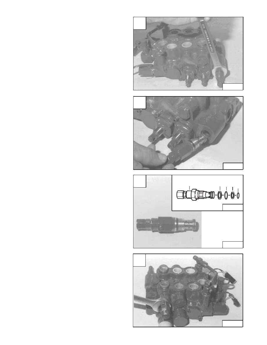
Main Relief Valve
Loosen the main relief valve [A].
Assemble: Always use new O–rings and back–up
washers. Tighten to 35–40 ft.–lbs. (47–54 Nm) torque.
Remove the main relief valve [B].
Remove the O–ring and back–up washers from the main
relief valve [C].
Port Relief Valve
Loosen the port relief valve [D].
Assemble: Always use new O–rings and back–up
washers. Tighten to 35–40 ft.–lbs. (47–54 Nm) torque.
NOTE: The port relief valve can be located on either
side of the control valve (E or F ports). (See
CONTROL VALVE Identification Chart Page
2–60.)
Revised Jan. 99
A
CD–10796
C
CD–10798
E–01509
1. Relief Valve
2. Back–up Washer
3. O–ring
4. O–ring
5. Back–up Washer
1
2 3 4 5
D
CD–10799
–2–62–
773 BICS Loader
Service Manual
B
CD–10797