Loader Bobcat 773. Manual - part 21


  Index      Bobcat     Bobcat 773 - service manual 1997 year


Search            


Content   ..  19  20  21  22   ..


Loader Bobcat 773. Manual - part 21


CONTROL VALVE (S/N 509640660 & Above, S/N
509616542 & Above) (Cont’d)

Removal And Installation (Cont’d)

Remove the right rear tire.

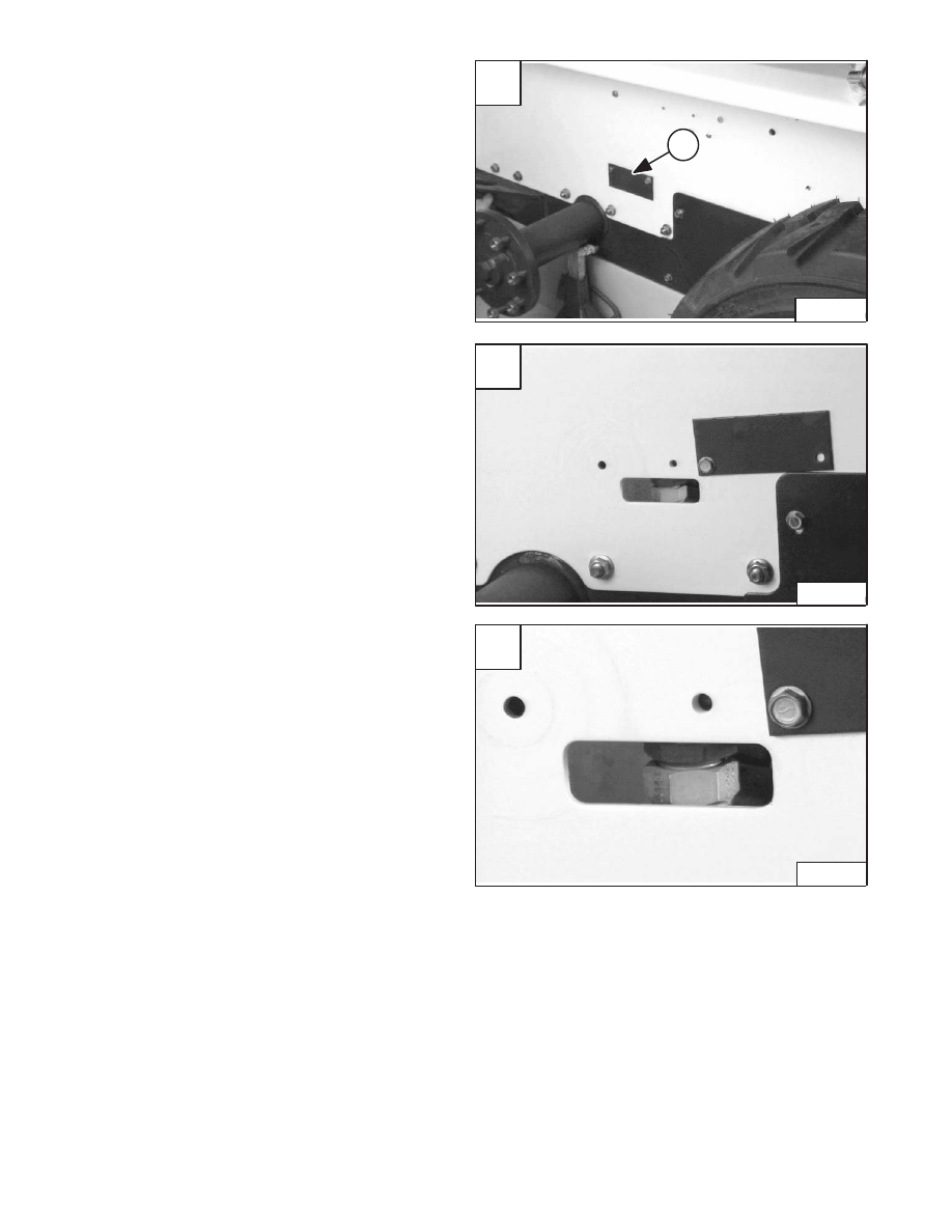
Locate the rectangular access cover (Item 1) [A] on the
right side of the loader frame.

Loosen one mounting bolt and remove the other
mounting bolt from the access cover [B].

Rotate the cover to expose the access slot in the loader
[B].

Disconnect the inlet hose from the control valve through
the access slot [C].

Remove the two control valve mounting bolts & nuts.

Remove the control valve from the loader.

Installation: Tighten the mounting bolt & nut to 18–20
ft.–lbs. (24–27 Nm) torque.

Reverse the removal procedure to install the control
valve.

A

P–04109

1

C

P–04110

–2–30–

773 BICS Loader

Service Manual

B

P–04108

A1

Lift Cylinder Base End/Restrictor

.134–141 (3,40–3,58 mm)

A2

Tilt Cylinder Base End

A3

Auxiliary Hydraulics

B1

Lift Cylinder Rod End

B2

Tilt Cylinder Rod End

B3

Auxiliary Hydraulics

C1

Load Check Valve/Lift Function

C2

Load Check Valve/Tilt Function

C3

Plug/Auxiliary Function

C4

Outlet Fluid Flow

D1

Lift Spool Detent

D2

Tilt Spool Centering Spring

D3

Auxiliary Spool/Centering Spring

E1

Port Relief Valve

E2

Anti–Cavitation Valve

Port Relief/Anti–Cavitation Valve

(If Equipped)

F1

Anti–Cavitation/Port Relief (optional) Valve

F2

Plug

Port Relief (If Equipped)

G1

Lift Spool End

G2

Tilt Spool End

G3

Auxiliary Spool/Centering Spring

H1

Auxiliary Electric Solenoid

H2

Plug or Auxiliary Port Relief (Optional)

H3

Auxiliary Electric Solenoid

MR

Main Relief Valve

CONTROL VALVE (S/N 509640660 & Above, S/N
509616542 & Above) (Cont’d)

Identification Chart

Item

773 Loader

Revised May 98                   

A

MC–02229

MR

G1

G2

G3

H1

D2

D3

D1

H2

F1

F2

C1

E1

E2

C2

C3

C4

A1

A2

A3

B1

B2

B3

H3

773 BICS Loader

–2–31–

Service Manual

CONTROL VALVE (S/N 509640660 & Above, S/N
509616542 & Above) (Cont’d)

Disassembly

Remove the BICS valve assembly from the control valve.
(See Page 2–20.)

Mark each anti–cavitation valve, port relief valve, plug,
spool and related parts for ease of assembly.

Bolt the control valve to a work bench for ease of
disassembly and assembly.

Remove the four large O–rings (Item 1) [A] and the small
O–ring (Item 2) [A] from the top of the control valve.

Remove the end caps (Item 1) [B] from the base end of
the lift and tilt sections.

Lift Base End Restrictor

Disassembly

Remove the restrictor (Item 1) [C] from the lift section
base end port.

Load Check Valve

Disassembly

Remove the load check plugs (Item 1) [D] from the lift and
tilt valve sections.

A

P–08950

2

1

1

C

P–08964

1

D

P–08965

1

–2–32–

773 BICS Loader

Service Manual

B

P–08963

1

1

CONTROL VALVE (S/N 509640660 & Above, S/N
509616542 & Above) (Cont’d)

Load Check Valve (Cont’d)

Disassembly (Cont’d)

Remove the spring (Item 1) [A] and poppet (Item 2) [A]
from the lift and tilt valve sections.

Remove the O–ring (Item 3) [A] from the plug.

Remove the plug (Item 1) [B].

Remove the O–ring (Item 1) [C] from the plug (Item 2) [C].

Main Relief Valve

Disassembly

Remove the main relief valve (Item 1) [D].

A

P–08966

3

1

2

C

P–11342

1

2

D

P–08969

1

773 BICS Loader

–2–33–

Service Manual

B

P–08967

1


Content   ..  19  20  21  22   ..