Audi TT (2007 year). Manual - part 174


  Главная      Audi     Audi TT (2007 year) (4-cylinder TDI engine (2.0 ltr. 4-valve common rail), mechanics Engine ID CBB) - Workshop Manual


поиск по сайту            


содержание   ..  172  173  174  175   ..


Audi TT (2007 year). Manual - part 174


Protected by copyright. Copying for private or commercial purposes, in part or in whole, is not 
 permitted unless authorised by AUDI AG. AUDI AG does not guarantee or accept any liability 
     with respect to the correctness of information in this document. Copyright by AUDI AG.

8J0-049040409

29

30

31

32

33

34

35

36

37

38

39

40

41

42

J

255

43

2

T16d/3

2

T16d/4

br/bl

0,35

N

280

3

sw/ro

0,5

6

1/31

br

0,5

G

65

388

T

4a/3

gn/sw

1,0

gn/sw

1,0

G

56

V

42

M

br

1,0

br

2,5

389

390

br

4,0

br

1,0

1

br

1,0

T

4a/4

672

br

2,5

366

br

6,0

372

✱✱

✱✱

6

ws = white

sw = black

ro

= red

br

= brown

gn

= green

bl

= blue

gr

= grey

li

= purple

ge

= yellow

or

= orange

rs

= pink

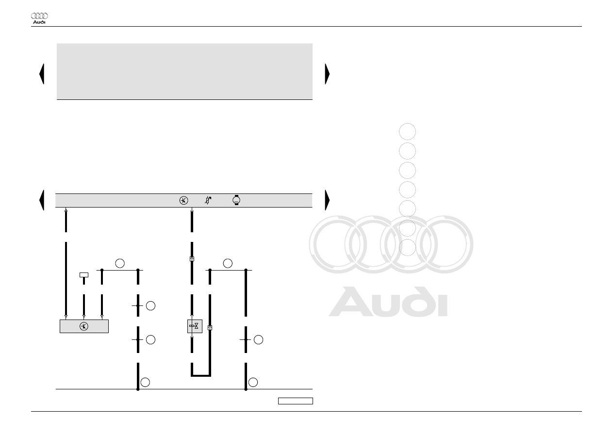
Climatronic control unit, dash panel temperature sensor,

high pressure sender, compressor regulating valve, air

conditioning system compressor regulating valve,

temperature sensor blower

G56 Dash panel temperature sensor

G65 High pressure sender

J255 Climatronic control unit

N280 Air conditioning system compressor regulating valve

T4a 4-pin connector, black, in front left engine compartment

T16d 16-pin connector, black, connector D, on Climatronic control unit

V42 Temperature sensor blower

43

Earth point, lower part of right A-pillar

366 Earth connection 1, in main wiring harness

372 Earth connection 7, in main wiring harness

388 Earth connection 23, in main wiring harness

389 Earth connection 24, in main wiring harness

390 Earth connection 25, in main wiring harness

672 Earth point 2, on front of left longitudinal member

*

Operating unit for air conditioning

**

not for Heater (9AA)

 Audi TT

Current Flow Diagram

No.  49 / 4

Edition  04.2009

Protected by copyright. Copying for private or commercial purposes, in part or in whole, is not 
 permitted unless authorised by AUDI AG. AUDI AG does not guarantee or accept any liability 
     with respect to the correctness of information in this document. Copyright by AUDI AG.

8J0-049050409

43

44

45

46

47

48

49

50

51

52

53

54

55

56

J

255

97

97

L31

L31

T12k/8

bl/ro

0,35

T12k/7

li/ge

0,35

T20k/6

gn/ws

0,35

M

2

6

5

G

143

V

113

1

3

br/ws

0,35

sw

0,35

T12k/9

ws/gn

0,35

T12k

/10

ge/gn

0,35

T20k/7

gr/gn

0,35

M

2

6

5

G

113

V

71

3

1

br/ws

0,35

sw

0,35

T20k/1

sw

0,35

T12k/5

ge

0,35

T12k/6

ws/ge

0,35

M

6

5

V

70

T20k/5

gr/ge

0,35

2

3

1

br/ws

0,35

sw

0,35

T20k

/14

br/ws

0,35

G

112

ws = white

sw = black

ro

= red

br

= brown

gn

= green

bl

= blue

gr

= grey

li

= purple

ge

= yellow

or

= orange

rs

= pink

Climatronic control unit, potentiometer for centre flap

control motor, potentiometer for air flow flap control motor,

potentiometer for air recirculation flap control motor

G112 Central flap control motor potentiometer

G113 Air flow flap control motor potentiometer

G143 Air recirculation flap control motor potentiometer

J255 Climatronic control unit

T12k 12-pin connector, connector A, on Climatronic control unit

T20k 20-pin connector, connector B, on Climatronic control unit

V70 Central flap control motor

V71 Air flow flap control motor

V113 Air recirculation flap control motor

97

Earth connection 1, in air conditioning system wiring harness

L31 Connection (5V), in air conditioning system wiring harness

*

Operating unit for air conditioning

 Audi TT

Current Flow Diagram

No.  49 / 5

Edition  04.2009

Protected by copyright. Copying for private or commercial purposes, in part or in whole, is not 
 permitted unless authorised by AUDI AG. AUDI AG does not guarantee or accept any liability 
     with respect to the correctness of information in this document. Copyright by AUDI AG.

8J0-049060409

57

58

59

60

61

62

63

64

65

66

67

68

69

70

J

255

97

97

L31

L31

T12k/3

ws/gr

0,35

T12k/4

ge/gn

0,35

T20k/4

gr

0,35

M

2

6

5

G

135

V

107

1

3

br/ws

0,35

sw

0,35

T12k

/11

ge/bl

0,35

T12k

/12

ws/bl

0,35

T20k/3

gr/bl

0,35

M

2

6

5

G

221

V

159

1

3

br/ws

0,35

sw

0,35

T12k/2

gn/ro

0,35

T12k/1

bl/sw

0,35

M

6

5

V

158

T20k/2

ws/bl

0,35

2

3

1

br/ws

0,35

sw

0,35

G

220

97

✱✱

✱✱

ws = white

sw = black

ro

= red

br

= brown

gn

= green

bl

= blue

gr

= grey

li

= purple

ge

= yellow

or

= orange

rs

= pink

Climatronic control unit, potentiometer for defroster flap

control motor, potentiometer for left temperature flap

control motor, potentiometer for right temperature flap

control motor

G135 Defroster flap control motor potentiometer

G220 Potentiometer for left temperature flap control motor

G221 Potentiometer for right temperature flap control motor

J255 Climatronic control unit

T12k 12-pin connector, connector A, on Climatronic control unit

T20k 20-pin connector, connector B, on Climatronic control unit

V107 Defroster flap control motor

V158 Left temperature flap control motor

V159 Right temperature flap control motor

97

Earth connection 1, in air conditioning system wiring harness

L31 Connection (5V), in air conditioning system wiring harness

*

Operating unit for air conditioning

**

not for Heater (9AA)

 Audi TT

Current Flow Diagram

No.  49 / 6

Edition  04.2009

Protected by copyright. Copying for private or commercial purposes, in part or in whole, is not 
 permitted unless authorised by AUDI AG. AUDI AG does not guarantee or accept any liability 
     with respect to the correctness of information in this document. Copyright by AUDI AG.

8J0-049070409

71

72

73

74

75

76

77

78

79

80

81

82

83

84

J

255

br/ws

0,35

T20k/8

gr/ro

0,35

2

G

261

1

T20k/9

bl

0,35

2

G

262

1

T20k/11

ro/sw

0,35

2

1

T16c

/14

ws/gn

0,35

4

G

263

3

97

97

T16d/2

ϑ

br/ws

0,35

br/ws

0,35

bl/gr

0,35

2

G

386

1

bl/gn

0,35

2

1

G

385

ϑ

ϑ

br/ws

0,35

br/ws

0,35

T16c

/15

sw/gn

0,35

1

T16d/1

ro/ge

0,35

2

411

G

107

ϑ

ϑ

411

T16c/5

#

##

br/ws

0,35

br/ws

0,35

#

##

✱✱

✱✱

✱✱

✱✱

✱✱

✱✱

✱✱

ws = white

sw = black

ro

= red

br

= brown

gn

= green

bl

= blue

gr

= grey

li

= purple

ge

= yellow

or

= orange

rs

= pink

Climatronic control unit, sunlight penetration photosensor,

left and right footwell vent temperature sender, evaporator

output temperature sender, front left and right chest vent

temperature sensor

G107 Sunlight penetration photosensor

G261 Left footwell vent temperature sender

G262 Right footwell vent temperature sender

G263 Evaporator out-flow temperature sender

G385 Front left chest vent temperature sensor

G386 Front right chest vent temperature sensor

J255 Climatronic control unit

T16c 16-pin connector, brown, connector C, on Climatronic control

unit

T16d 16-pin connector, black, connector D, on Climatronic control unit

T20k 20-pin connector, connector B, on Climatronic control unit

97

Earth connection 1, in air conditioning system wiring harness

411 Earth connection 2 (sender earth), in main wiring harness

*

Operating unit for air conditioning

**

not for Heater (9AA)

#

left-hand drive only

##

right-hand drive only

 Audi TT

Current Flow Diagram

No.  49 / 7

Edition  04.2009


содержание   ..  172  173  174  175   ..