Audi TT (2007 year). Manual - part 84


  Главная      Audi     Audi TT (2007 year) (4-cylinder TDI engine (2.0 ltr. 4-valve common rail), mechanics Engine ID CBB) - Workshop Manual


поиск по сайту            


содержание   ..  82  83  84  85   ..


Audi TT (2007 year). Manual - part 84


Protected by copyright. Copying for private or commercial purposes, in part or in whole, is not 
 permitted unless authorised by AUDI AG. AUDI AG does not guarantee or accept any liability 
     with respect to the correctness of information in this document. Copyright by AUDI AG.

8J0-007030806

15

16

17

18

19

20

21

22

23

24

25

26

27

28

J

255

43

4

T

10l/2

ro/bl

4,0

SB

8

30A

ro/bl

2,5

89

8a

B272

ro/ws

4,0

21

B407

V

2

T16c/12

or/br

0,35

ro

6,0

B272

SB

9

25A

9a

9

8

ro/bl

4,0

21

SB

12

40A

12a

12

ST1

or/br

0,35

or/br

0,35

T12e/7

B406

or/br

0,35

T20d

/5

J

519

J

533

E

230 ✱ ✱

B398

T16c/13

or/gn

0,35

or/gn

0,35

T12e/8

B397

T20d/15

J

519

J

533

or/gn

0,35

or/gn

0,35

2

sw/ws

0,35

T20k

/19

1

bl/ws

0,35

T20k

/20

3/31

T

10l

/1

br

4,0

br

4,0

J

126

M

89

21

21

ws = white

sw = black

ro

= red

br

= brown

gn

= green

bl

= blue

gr

= grey

li

= purple

ge

= yellow

or

= orange

rs

= pink

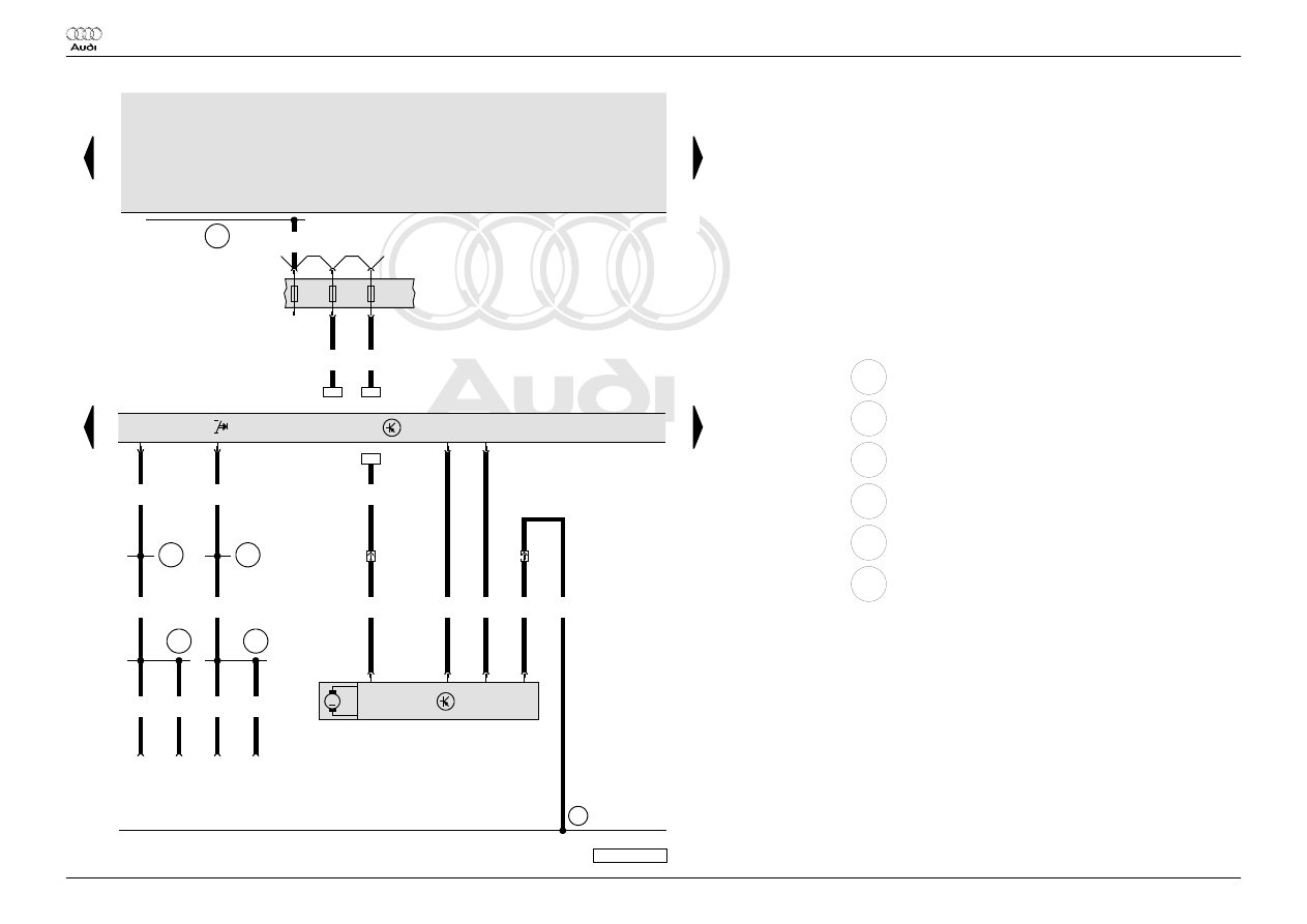
Climatronic control unit, fresh air blower control unit, fresh

air blower

E230 Heated rear window button

J126 Fresh air blower control unit

J255 Climatronic control unit

J519 Onboard supply control unit

J533 Data bus diagnostic interface

SB8 Fuse 8 on fuse holder B

SB9 Fuse 9 on fuse holder B

SB12 Fuse 12 on fuse holder B

T10l 10-pin connector, black, behind the dash panel on right

T12e 12-pin connector, black, connector G, on onboard power supply

control unit

T16c 16-pin connector, brown, connector C, on Climatronic control

unit

T20d 20-pin connector, black, on data bus diagnostic interface

T20k 20-pin connector, connector B, on Climatronic control unit

V2

Fresh air blower

43

Earth point, lower part of right A-pillar

B272 Positive connection (30), in main wiring harness

B397 Connection 1 (convenience CAN bus, high), in main wiring

harness

B398 Connection 2 (convenience CAN bus, high), in main wiring

harness

B406 Connection 1 (convenience CAN bus, low), in main wiring

harness

B407 Connection 2 (convenience CAN bus, low), in main wiring

harness

CAN bus (data wire)

*

Operating unit for air conditioning

**

Operation for heated rear window via CAN bus, heated rear

window see CFD basic equipment

 Audi TT

Current Flow Diagram

No.  7 / 3

Edition  10.2008

Protected by copyright. Copying for private or commercial purposes, in part or in whole, is not 
 permitted unless authorised by AUDI AG. AUDI AG does not guarantee or accept any liability 
     with respect to the correctness of information in this document. Copyright by AUDI AG.

8J0-007041008

29

30

31

32

33

34

35

36

37

38

39

40

41

42

J

255

43

2

T16d/3

2

T16d/4

br/bl

0,35

N

280

3

sw/ro

0,5

6

1/31

br

0,5

G

65

388

T

4a/3

gn/sw

1,0

gn/sw

1,0

G

56

V

42

M

br

1,0

br

2,5

389

390

br

4,0

br

1,0

1

br

1,0

T

4a/4

672

br

2,5

366

br

6,0

372

✱✱

✱✱

6

ws = white

sw = black

ro

= red

br

= brown

gn

= green

bl

= blue

gr

= grey

li

= purple

ge

= yellow

or

= orange

rs

= pink

Climatronic control unit, dash panel temperature sensor,

high pressure sender, compressor regulating valve, air

conditioning system compressor regulating valve,

temperature sensor blower

G56 Dash panel temperature sensor

G65 High pressure sender

J255 Climatronic control unit

N280 Air conditioning system compressor regulating valve

T4a 4-pin connector, black, in front left engine compartment

T16d 16-pin connector, black, connector D, on Climatronic control unit

V42 Temperature sensor blower

43

Earth point, lower part of right A-pillar

366 Earth connection 1, in main wiring harness

372 Earth connection 7, in main wiring harness

388 Earth connection 23, in main wiring harness

389 Earth connection 24, in main wiring harness

390 Earth connection 25, in main wiring harness

672 Earth point 2, on front of left longitudinal member

*

Operating unit for air conditioning

**

not for Heater (9AA)

 Audi TT

Current Flow Diagram

No.  7 / 4

Edition  10.2008

Protected by copyright. Copying for private or commercial purposes, in part or in whole, is not 
 permitted unless authorised by AUDI AG. AUDI AG does not guarantee or accept any liability 
     with respect to the correctness of information in this document. Copyright by AUDI AG.

8J0-007050806

43

44

45

46

47

48

49

50

51

52

53

54

55

56

J

255

97

97

L31

L31

T12k/8

bl/ro

0,35

T12k/7

li/ge

0,35

T20k/6

gn/ws

0,35

M

2

6

5

G

143

V

113

1

3

br/ws

0,35

sw

0,35

T12k/9

ws/gn

0,35

T12k

/10

ge/gn

0,35

T20k/7

gr/gn

0,35

M

2

6

5

G

113

V

71

3

1

br/ws

0,35

sw

0,35

T20k/1

sw

0,35

T12k/5

ge

0,35

T12k/6

ws/ge

0,35

M

6

5

V

70

T20k/5

gr/ge

0,35

2

3

1

br/ws

0,35

sw

0,35

T20k

/14

br/ws

0,35

G

112

ws = white

sw = black

ro

= red

br

= brown

gn

= green

bl

= blue

gr

= grey

li

= purple

ge

= yellow

or

= orange

rs

= pink

Climatronic control unit, potentiometer for centre flap

control motor, potentiometer for air flow flap control motor,

potentiometer for air recirculation flap control motor

G112 Central flap control motor potentiometer

G113 Air flow flap control motor potentiometer

G143 Air recirculation flap control motor potentiometer

J255 Climatronic control unit

T12k 12-pin connector, connector A, on Climatronic control unit

T20k 20-pin connector, connector B, on Climatronic control unit

V70 Central flap control motor

V71 Air flow flap control motor

V113 Air recirculation flap control motor

97

Earth connection 1, in air conditioning system wiring harness

L31 Connection (5V), in air conditioning system wiring harness

*

Operating unit for air conditioning

 Audi TT

Current Flow Diagram

No.  7 / 5

Edition  10.2008

Protected by copyright. Copying for private or commercial purposes, in part or in whole, is not 
 permitted unless authorised by AUDI AG. AUDI AG does not guarantee or accept any liability 
     with respect to the correctness of information in this document. Copyright by AUDI AG.

8J0-007061008

57

58

59

60

61

62

63

64

65

66

67

68

69

70

J

255

97

97

L31

L31

T12k/3

ws/gr

0,35

T12k/4

ge/gn

0,35

T20k/4

gr

0,35

M

2

6

5

G

135

V

107

1

3

br/ws

0,35

sw

0,35

T12k

/11

ge/bl

0,35

T12k

/12

ws/bl

0,35

T20k/3

gr/bl

0,35

M

2

6

5

G

221

V

159

1

3

br/ws

0,35

sw

0,35

T12k/2

gn/ro

0,35

T12k/1

bl/sw

0,35

M

6

5

V

158

T20k/2

ws/bl

0,35

2

3

1

br/ws

0,35

sw

0,35

G

220

97

✱✱

✱✱

ws = white

sw = black

ro

= red

br

= brown

gn

= green

bl

= blue

gr

= grey

li

= purple

ge

= yellow

or

= orange

rs

= pink

Climatronic control unit, potentiometer for defroster flap

control motor, potentiometer for left temperature flap

control motor, potentiometer for right temperature flap

control motor

G135 Defroster flap control motor potentiometer

G220 Potentiometer for left temperature flap control motor

G221 Potentiometer for right temperature flap control motor

J255 Climatronic control unit

T12k 12-pin connector, connector A, on Climatronic control unit

T20k 20-pin connector, connector B, on Climatronic control unit

V107 Defroster flap control motor

V158 Left temperature flap control motor

V159 Right temperature flap control motor

97

Earth connection 1, in air conditioning system wiring harness

L31 Connection (5V), in air conditioning system wiring harness

*

Operating unit for air conditioning

**

not for Heater (9AA)

 Audi TT

Current Flow Diagram

No.  7 / 6

Edition  10.2008


содержание   ..  82  83  84  85   ..