Acura RSX Honda Integra. Manual - part 75


  Index      Acura     Acura RSX Honda Integra - service repair manual 2002-2006 year


Search            


Content   ..  73  74  75  76   ..


Acura RSX Honda Integra. Manual - part 75


*01

03

How to Troubleshoot Circuits at the ECM/
PCM

ECM/PCM Updating and Substitution for
Testing

How to Update the ECM/PCM

Special Tools Required

Special Tools Required

11-6

Fuel and Emissions Systems

General Troubleshooting Information (cont’d)

07SAZ-001000A

B

A

C

A

B

• Digital multimeter KS-AHM-32-003 (1) or a

commercially available digital multimeter

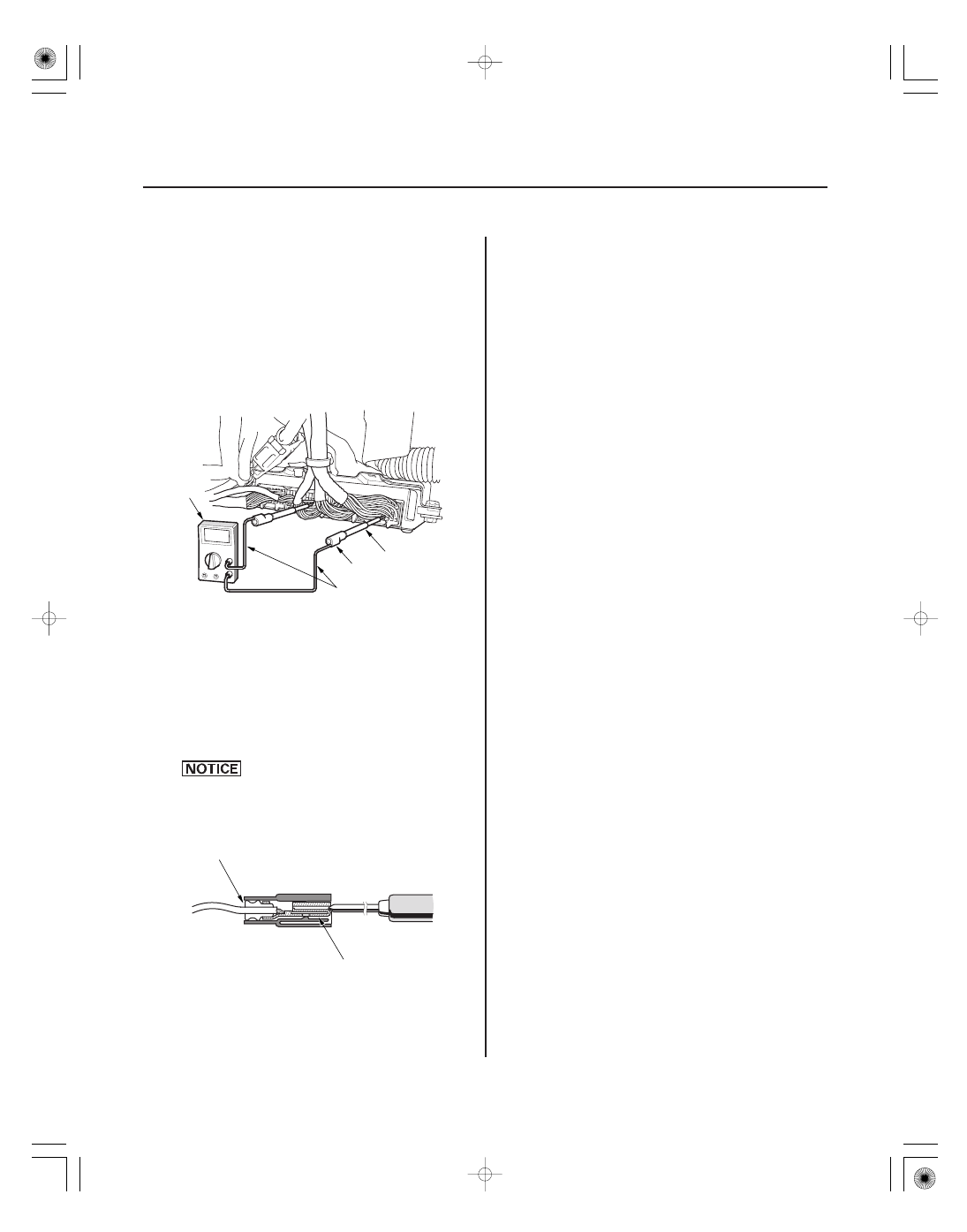
• Backprobe set 07SAZ-001000A (2)

1. Connect the backprobe adapters (A) to the stacking

patch cords (B), and connect the cords to a digital
multimeter (C).

2. Using the wire insulation as a guide for the

contoured tip of the backprobe adapter, gently slide
the tip into the connector from the wire side until it
touches the end of the wire terminal.

3. If you cannot get to the wire side of the connector

or the wire side is sealed (A), disconnect the
connector and probe the terminals (B) from the
terminal side. Do not force the probe into the
connector.

Do not puncture the insulation on a wire.
Punctures can cause poor or intermittent
electrical connections.

Honda interface module (HIM) EQS05A35570

Use this procedure when you have to substitute a
known-good ECM/PCM in a troubleshooting procedure.
Update the ECM/PCM only if the ECM/PCM does not
have the latest software loaded.

NOTE: Do not turn the ignition switch OFF while
updating the ECM/PCM. If you turn the ignition switch
OFF before completion, the ECM/PCM can be damaged.

NOTE:

• To ensure the latest program is installed, do an ECM/

PCM update whenever the ECM/PCM is substituted or
replaced.

• You can not update an ECM/PCM with the program it

already has. It will only accept a new program.

• Before you update the ECM/PCM, make sure the

vehicle’s battery is fully charged.

• To prevent ECM/PCM damage, do not operate

anything electrical (audio system, brakes, A/C, power
windows, moonroof, door locks, etc.) during the
update.

• If you need to diagnose the Honda interface module

(HIM) because the HIM’s red (

3) light came on or

was flashing during the update, leave the ignition
switch in the ON (II) position when you disconnect the
HIM from the data link connector (DLC). This will
prevent ECM/PCM damage.

1. Turn the ignition switch ON (II). Do not start the

engine.

05/06/27 17:31:11 61S6M040_110_0006

04

05

How to Substitute the ECM/PCM (2002-2004
Models)

How to Substitute the ECM/PCM (2005-2006
Models)

11-7

A

A

2. Connect the HDS or the Honda interface module

(HIM) to the data link connector (DLC) (A) located
under the driver’s side of the dashboard.

3. Do the ECM/PCM update procedure as described

on the HIM label and in the ECM/PCM update
system.

4. Do the ECM/PCM idle learn procedure, 2002-2004

models (see page 11-349), 2005-2006 models
(see page 11-349).

5. 2005-2006 models: Clear the CKP pattern with the

HDS while the engine is stopped.

1. Remove the ECM/PCM from the vehicle.

2. Install a known-good ECM/PCM.

3. Rewrite the immobilizer code with the ECM/PCM

replacement procedure from the HDS; it allows you
to start the engine.

4. After completing your tests, install the original

ECM/PCM and rewrite the immobilizer code with
the ECM/PCM replacement procedure with the HDS.

5. Do the ECM/PCM idle learn procedure (see page

11-349).

1. Connect the HDS to the data link connector (DLC)

(A) located under the driver’s side of the dashboard.

2. Jump the SCS line with the HDS.

(cont’d)

05/06/27 17:31:11 61S6M040_110_0007

06

OBD Status (2005-2006 Models)

11-8

Fuel and Emissions Systems

General Troubleshooting Information (cont’d)

A

B

C

D

3. Remove the passenger’s dashboard lower cover

(A) (see page 20-67).

4. Disconnect the ECM/PCM connectors (B).

5. Remove the ECM/PCM mounting bolts (C) and the

ECM/PCM (D).

6. Install the ECM/PCM in the reverse order of

removal.

7. Open the SCS with the HDS.

8. Turn the ignition switch ON (II).

NOTE: DTC: P0630 ‘‘VIN Not Programmed or
Mismatch’’ may be stored because the VIN has not
been programmed into the ECM/PCM; ignore it,
and continue this procedure.

9. Input the VIN to the ECM/PCM with the HDS.

10. Rewrite the immobilizer code with the ECM/PCM

replacement procedure in the HDS; it allows you to
start the engine.

11. Reset the ECM/PCM with the HDS.

12. Do the ECM/PCM idle learn procedure (see page

11-349).

13. Do the CKP pattern learn procedure.

The OBD status shows the current system status of
each DTC and all of the parameters. This function is
used to see if the technician’s repair was successfully
finished. The results of diagnostic tests for the DTC are
displayed as:

• PASSED: On board diagnosis is successfully finished.
• FAILED: On board diagnosis has finished but failed.
• EXECUTING: The vehicle is in enable criteria

conditions for the DTC and the on board diagnosis is
running.

• NOT COMPLETED: The on board diagnosis was

running but is out of the enable conditions of the DTC.

• OUT OF CONDITION: The vehicle has stayed out of

the enable conditions of the DTC.

05/06/27 17:31:11 61S6M040_110_0008

―――

―――
―――
―――
―――
―――

―――
―――
―――
―――


―――
―――

―――


S6M6AZFA20300000000GAAT00

2002-2004 Models

DTC

(MIL indication )

Two Drive Cycle

Detection

Detection Item

MIL

Note

11-9

DTC Troubleshooting Index

P0010 (56)

Variable Valve Timing Control (VTC) Oil Control Solenoid Valve
Malfunction

ON

(see page 11-286)

P0011 (56)

Variable Valve Timing Control (VTC) System Malfunction

ON

(see page 11-291)

P0107 (3)

Manifold Absolute Pressure (MAP) Sensor Circuit Low Voltage

ON

(see page 11-98)

P0108 (3)

Manifold Absolute Pressure (MAP) Sensor Circuit High Voltage

ON

(see page 11-101)

P0112 (10)

Intake Air Temperature (IAT) Sensor Circuit Low Voltage

ON

(see page 11-108)

P0113 (10)

Intake Air Temperature (IAT) Sensor Circuit High Voltage

ON

(see page 11-110)

P0116 (86)

Engine Coolant Temperature (ECT) Sensor Circuit Range/
Performance Problem

ON

(see page 11-114)

P0117 (6)

Engine Coolant Temperature (ECT) Sensor Circuit Low Voltage

ON

(see page 11-116)

P0118 (6)

Engine Coolant Temperature (ECT) Sensor Circuit High Voltage

ON

(see page 11-118)

P0122 (7)

Throttle Position (TP) Sensor Circuit Low Voltage

ON

(see page 11-122)

P0123 (7)

Throttle Position (TP) Sensor Circuit High Voltage

ON

(see page 11-127)

P0125 (86)

Engine Coolant Temperature (ECT) Sensor Malfunction/Slow
Response

ON

(see page 11-130)

P0128 (87)

Cooling System Malfunction

ON

(see page 11-132)

P0133 (61)

Air Fuel Ratio (A/F) Sensor (Sensor 1) Slow Response

ON

(see page 11-135)

P0134 (41)

Air Fuel Ratio (A/F) Sensor (Sensor 1) Heater System Malfunction

ON

(see page 11-137)

P0135 (41)

Air Fuel Ratio (A/F) Sensor (Sensor 1) Heater Circuit Malfunction

ON

(see page 11-139)

P0137 (63)

Secondary Heated Oxygen Sensor (Secondary HO2S (Sensor 2))
Circuit Low Voltage

ON

(see page 11-146)

P0138 (63)

Secondary Heated Oxygen Sensor (Secondary HO2S (Sensor 2))
Circuit High Voltage

ON

(see page 11-149)

P0139 (63)

Secondary Heated Oxygen Sensor (Secondary HO2S (Sensor 2))
Slow Response

ON

(see page 11-154)

P0141 (65)

Secondary Heated Oxygen Sensor (Secondary HO2S (Sensor 2))
Heater Circuit Malfunction

ON

(see page 11-156)

P0171 (45)

Fuel System Too Lean

ON

(see page 11-161)

P0172 (45)

Fuel System Too Rich

ON

(see page 11-161)

P0300
and some of
P0301 (71)
P0302 (72)
P0303 (73)
P0304 (74)

Random Misfire Detected

ON

(see page 11-163)

P0301 (71)

No. 1 Cylinder Misfire Detected

ON

(see page 11-167)

P0302 (72)

No. 2 Cylinder Misfire Detected

ON

(see page 11-167)

P0303 (73)

No. 3 Cylinder Misfire Detected

ON

(see page 11-167)

P0304 (74)

No. 4 Cylinder Misfire Detected

ON

(see page 11-167)

: These DTCs are indicated by a blinking MIL when the SCS line is jumped with the HDS.
6: 2004 model
7: 2003-2004 models

(cont’d)

6

6

7

6

05/06/27 17:31:11 61S6M040_110_0009


Content   ..  73  74  75  76   ..