Acura RL (1996-2004 year). Manual - part 713


  Index      Acura     Acura RL 1996-2004 year - service repair manual


Search            


Content   ..  711  712  713  714   ..


Acura RL (1996-2004 year). Manual - part 713


DTC 15-1

CAUTION: Whenever the ignition switch is ON (II), or

has been turned OFF for less than 3 minutes, be careful
not to bump the SRS unit or the side impact sensor; the

airbags could accidentally deploy and cause damage or
injuries.

Read the DTC:

1. Make sure nothing is sitting on the front passenger's seat.

2. Initialize the OPDS unit (see page 

24-88

).

3. Erase the DTC memory (see page 

24-87

).

4. Read the DTC (see page 

24-84

).

Is DTC 15-1 indicated?

YES

NO

Intermittent failure, system is OK at this time. See
Troubleshooting Intermittent Failures on page 

24-87

.

Check the fuse:
Check the No. 23 (7.5 A) fuse in the under-dash fuse/relay

box.

Is the fuse OK?

YES

NO

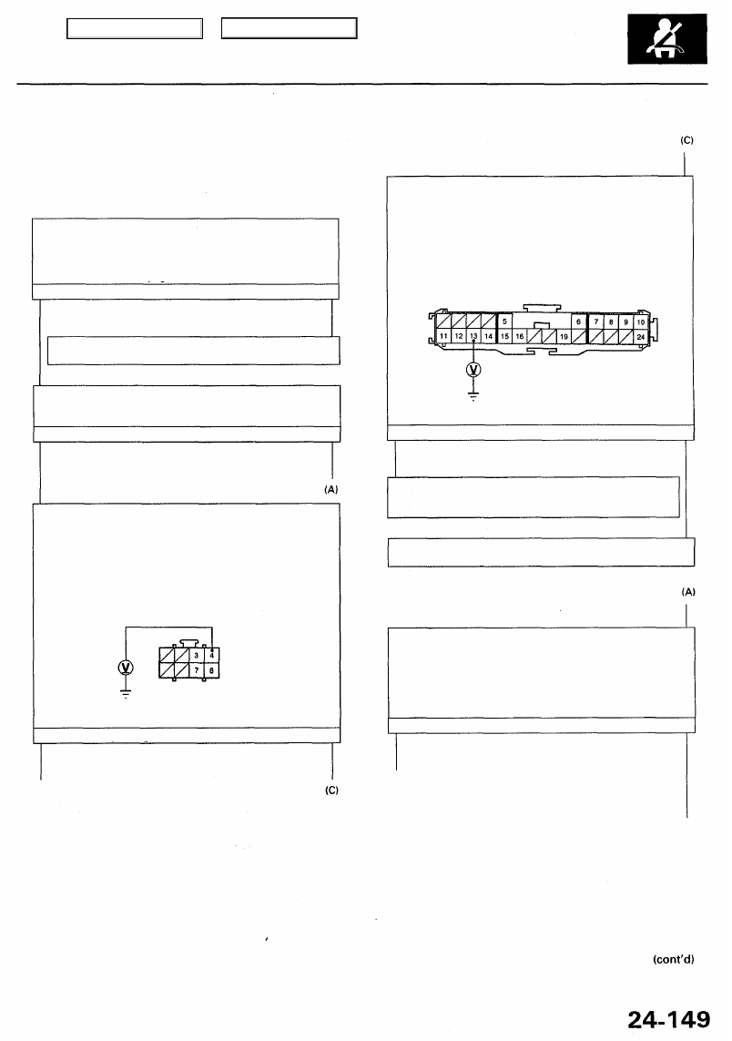
Check the power supply (1):

1. Disconnect the ODPS unit wire harness 8P connector

from the OPDS unit (see page 

24-92

).

2. Turn the ignition switch ON (II).
3. Check for voltage between the No. 4 terminal of the

ODPS unit wire harness 8P connector and body ground.
There should be battery voltage.

Wire side of female terminals

Is there battery voltage?

YES

(B) To page 

24-150

NO

Check the power supply (2):

1. Turn the ignition switch OFF.

2. Disconnect the main wire harness 24P connector from the

right side wire harness (see page 

24-97

).

3. Turn the ignition switch ON (II).
4. Check for voltage between the No. 13 terminal of the

main wire harness 24P connector and body ground.

There should be battery voltage.

Terminal side of male terminals

Is there battery voltage?

YES

NO

Short to power in the right side wire harness or OPDS unit
harness; if the OPDS unit harness is OK, replace the right
side wire harness.

Short to power in the main wire harness; replace the main
wire harness.

Check the fuse:

1. Replace the No. 23 (7.5 A) fuse in the under-dash

fuse/relay box.

2. Turn the ignition switch OFF after the ignition switch has

been turned on for 30 seconds.

3. Check the No. 23 (7.5 A) fuse in the under-dash fuse/relay

box (see page 

24-92

).

Is the fuse OK?

YES

NO

END

To page 

24-150

 (D)

Main Menu

Table of Contents

Troubleshooting - '99 - 01 Models

DTC 15-1 (cont'd)

From page 

24-149

 (D)

Check for a short to ground (1):

1. Replace the No. 23 (7.5 A) fuse in the under-dash

fuse/relay box (see page 

24-92

).

2. Disconnect the main wire harness 12P connector from

the under-dash fuse/relay box (see page 

24-92

).

3. Turn the ignition switch ON (II) for 30 seconds, then turn

it OFF.

4. Check the No. 23 (7.5 A) fuse in the under-dash fuse/relay

box (see page 

24-92

).

Short to ground in the No. 23 (7.5 A) related circuit; refer
to 

section 23

 and continue troubleshooting.

Check for a short to ground (3):

1. Disconnect the ODPS unit wire harness 8P connector

from the ODPS unit (see page

 24-92

).

2. Reconnect the right side wire harness 24P connector (see

page 

24-97

).

3. Turn the ignition switch ON (II) for 30 seconds, then turn

it OFF.

4. Check the No. 23 (7.5 A) fuse in the under-dash fuse/relay

box.

Check for a short to ground (2):

1. Disconnect the main wire harness 24P connector from

the right side wire harness (see page 

24-97

).

2. Connect the main wire harness 12P connector to the

under-dash fuse/relay box (see page 

24-92

).

3. Turn the switch ON (II) for 30 seconds, then turn it OFF.
4. Check the No. 23 (7.5 A) fuse in the under-dash fuse/relay

box.

(B) From page 

24-149

(F) To page 

24-151

Main Menu

Table of Contents

(F) From page 

24-150

Check for a short to ground between the right side wire

harness and the SRS floor harness (1):

1. Disconnect between the driver's seat belt tensioner 2P

and the left side wire harness 2P connectors, between
the front passenger's seat belt tensioner 2P and the right
side wire harness 2P connectors, between the driver's
side airbag 2P and the SRS floor harness 2P connectors,
and between the front passenger's side airbag 2P and

the SRS floor harness 2P connectors (see page 

24-95

24-96

)

2. Disconnect the SRS floor harness 18P connector from

SRS unit (see page

 24-92

).

3. Check resistance between the No. 10 terminal of the SRS

floor harness 18P connector and body ground.
There should be 1 or more.

Check for a short to ground between the right side wire
harness and the SRS floor harness (3):

1. Disconnect the main wire harness 14P connector (see

pag

24-93

).

2. Check resistance between the No. 10 terminal of the SRS

floor harness 18P connector and body ground.
There should be 1 or more.

(G) To page

 24-152

Check for a short to ground between the right side wire
harness and the SRS floor harness (2):

1. Disconnect the right side wire harness 24P connector

(see page 

24-97

).

2. Check resistance between the No. 10 terminal of the SRS

floor harness 18P connector and body ground.
There should be 1 or more.

Check for a short to ground between the right side wire
harness and SRS floor harness (4):

1. Disconnect the left side wire harness 2P connector (see

page 

24-93

).

2. Check resistance between the No. 10 terminal of the SRS

floor harness 18P connector and the body ground.
There should be 1 or more.

Main Menu

Table of Contents

DTC 15-1 (cont'd)

(G) From page 

24-151

Troubleshooting - '99 - 01 Models

(K) To page 

24-153

Check for a short to power between the right side wire har-
ness and the SRS floor harness
 (2):

1. Turn the ignition switch OFF.

2. Disconnect the main wire harness 24P connector (see

page

 24-97

).

3. Turn the ignition switch ON (II).
4. Check for voltage between the No. 10 terminal of the

SRS floor harness 18P connector and body ground.
There should be 0.5 V or less.

Check for an open between the right side wire harness and
SRS floor harness
 (2):

1. Disconnect the main wire harness 24P connector (see

page 

24-97

).

2. Check resistance between the No. 10 terminal of the SRS

floor harness 18P connector and the No. 5 terminal of the

main wire harness 24P connector.

There should be 0 - 1.0

To page 

24-154 

(J)

To page 

24-153

 (L)

Main Menu

Table of Contents


Content   ..  711  712  713  714   ..