Acura RL (1996-2004 year). Manual - part 421
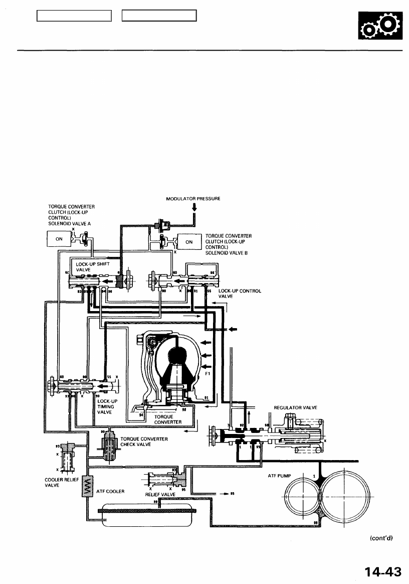
Full Lock-up
Torque Converter Clutch (Lock-up Control) Solenoid Valve A: ON Torque Converter Clutch (Lock-up Control) Solenoid
Valve B: ON
When the vehicle speed further increases, throttle B pressure is increased in accordance with the throttle opening.
Throttle B pressure (55) flows to the right side of the lock-up timing valve and the lock-up control valve, and they are moved
to the left side. The lock-up timing valve covers the port leading torque converter pressure (90) from the torque converter to
the lock-up control valve. The lock-up control valve uncovers the port to leak the torque converter pressure (94) and (96). As
this takes place, torque converter back pressure is released fully, causing the lock-up clutch to be engaged fully.
NOTE: When used, "left" or "right" indicates direction on the hydraulic circuit.
THROTTLE B PRESSURE
Main Menu
Table of Contents