Acura RL. Manual - part 792


  Index      Acura     Acura RL - service repair manual 2005-2008 year


Search            


Content   ..  790  791  792  793   ..


Acura RL. Manual - part 792


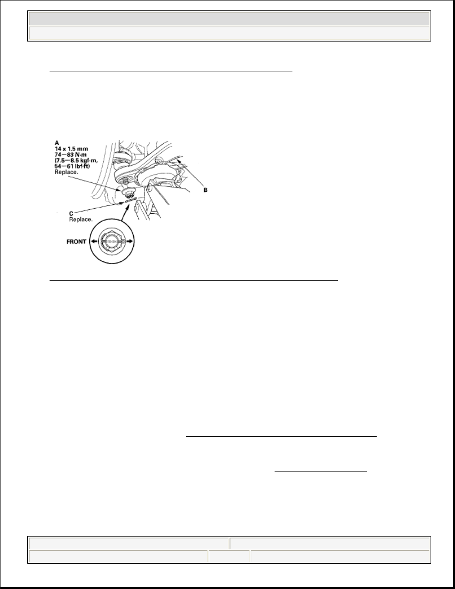
Fig. 49: Identifying Spring, Lower Spring Seat And Lower Arm
Courtesy of AMERICAN HONDA MOTOR CO., INC.
 

3. Place the floor jack at the connecting point of lower arm B and the stabilizer link.  

4. Raise the jack slowly until you can align the bolt hole of lower arm B and the knuckle ball joint pin, then 

loosely install the new castle nut (A). 

Fig. 50: Identifying Lower Arm And Castle Nut With Torque Specifications 
Courtesy of AMERICAN HONDA MOTOR CO., INC. 

5. Install the stabilizer link on the lower arm B with the washer and the new self-locking nut, and lightly 

tighten them.  

6. Raise the rear suspension with a floor jack to load it with the vehicle's weight.  

7. Tighten the castle nut and self-locking nut to the specified torque value. 

8. Clean the mating surface of the brake disc/drum and the inside of the wheel, then install the rear wheel.  

9. Check the rear wheel alignment, and adjust it if necessary (see WHEEL ALIGNMENT ). 

NOTE:

Torque the castle nut to the lower torque specification, then tightens 
if only far enough to align the slot with the ball joint pin hole. Do not 
align the castle nut by loosening it.  

Insert a new cotter pin (C) into the ball joint pin from the rear to the 
front of the vehicle, and bend its end as shown.  

Refer to stabilizer Link Replacement to connect the lower arm B and 
the link (see STABILIZER LINK REMOVAL/INSTALLATION ).  


2007 Acura RL 

2005-08 SUSPENSION Rear Suspension - RL


me 


Friday, June 05, 2009 1:21:25 PM

Page 30 

© 2005 Mitchell Repair Information Company, LLC. 

2007-08 ELECTRICAL

Relays - RL 

POWER RELAY TEST 

Use this chart to identify the type of relay, then do the test listed for it. 

POWER RELAY REFERENCE 

NORMALLY-OPEN TYPE A 

Check for continuity between the terminals. 

There should be continuity between the No. 1 and No. 2 terminals when power is connected to the No. 
4 terminal and ground the No. 3 terminal.  

There should be no continuity between the No. 1 and No. 2 terminals when power is disconnected. 

NOTE:

For the turn signal/hazard relay 1 input test (see TURN SIGNAL/HAZARD 
RELAY 1 INPUT TEST ).

Relay

Test

A/C compressor clutch relay

Normally-open type

Accessory power socket relay
A/F sensor relay
Blower motor relay
Control motor relay (HVAC)
Fog light relay
Fuel fill door open relay
Ignition coil relay
Headlight washer relay (Canada models)
PGM-FI main relay 1,2
Radiator fan control (RFC) unit relay
Rear window defogger relay
Starter cut relay 1,2
Seat heater relay
SH-AWD relay
Throttle actuator control module relay
Windshield wiper motor relay
Daytime running lights relay (Canada models)

Five-terminal type

ACC cut relay
IG2 cut relay
Adaptive cruise control relay ('06-08 models)
Turn signal/hazard relay 2 (sounder)

Turn signal/ hazard relay 2


2007 Acura RL 

2007-08 ELECTRICAL Relays - RL


2007 Acura RL 

2007-08 ELECTRICAL Relays - RL


me 


Friday, June 05, 2009 2:39:25 PM

Page 1 

© 2005 Mitchell Repair Information Company, LLC. 

me 


Friday, June 05, 2009 2:39:29 PM

Page 1 

© 2005 Mitchell Repair Information Company, LLC. 

Fig. 1: Checking Continuity Between No. 1 And No. 2 Terminals Of Power Relay 
Courtesy of AMERICAN HONDA MOTOR CO., INC. 

Radiator fan relay  

Fig. 2: Identifying Radiator Fan Relay Terminals 
Courtesy of AMERICAN HONDA MOTOR CO., INC. 

NORMALLY-OPEN TYPE B 

Check for continuity between the terminals. 

There should be continuity between the No. 1 and No. 3 terminals when power and ground are 
connected to the No. 2 and No. 4 terminals.  

There should be no continuity between the No. 1 and No. 3 terminals when power is disconnected. 


2007 Acura RL 

2007-08 ELECTRICAL Relays - RL


me 


Friday, June 05, 2009 2:39:25 PM

Page 2 

© 2005 Mitchell Repair Information Company, LLC. 

Fig. 3: Checking Continuity Between No. 1 And No. 3 Terminals Power And Ground 
Courtesy of AMERICAN HONDA MOTOR CO., INC. 

NORMALLY-OPEN TYPE C 

Check for continuity between the terminals. 

There should be continuity between the No. 1 and No. 3 terminals when battery positive terminal is 
connected to the No. 2 terminal, and battery negative terminal is connected to the No. 4 terminal.  

There should be no continuity between the No. 1 and No. 3 terminals when power is disconnected. 

Fig. 4: Checking Continuity Between No. 1 And No. 3 Terminals 
Courtesy of AMERICAN HONDA MOTOR CO., INC. 

Control motor relay (HVAC)  


2007 Acura RL 

2007-08 ELECTRICAL Relays - RL


me 


Friday, June 05, 2009 2:39:25 PM

Page 3 

© 2005 Mitchell Repair Information Company, LLC. 


Content   ..  790  791  792  793   ..