Acura RL. Manual - part 152
and between the No. 20 terminal and body ground. There should be 1 V or less.
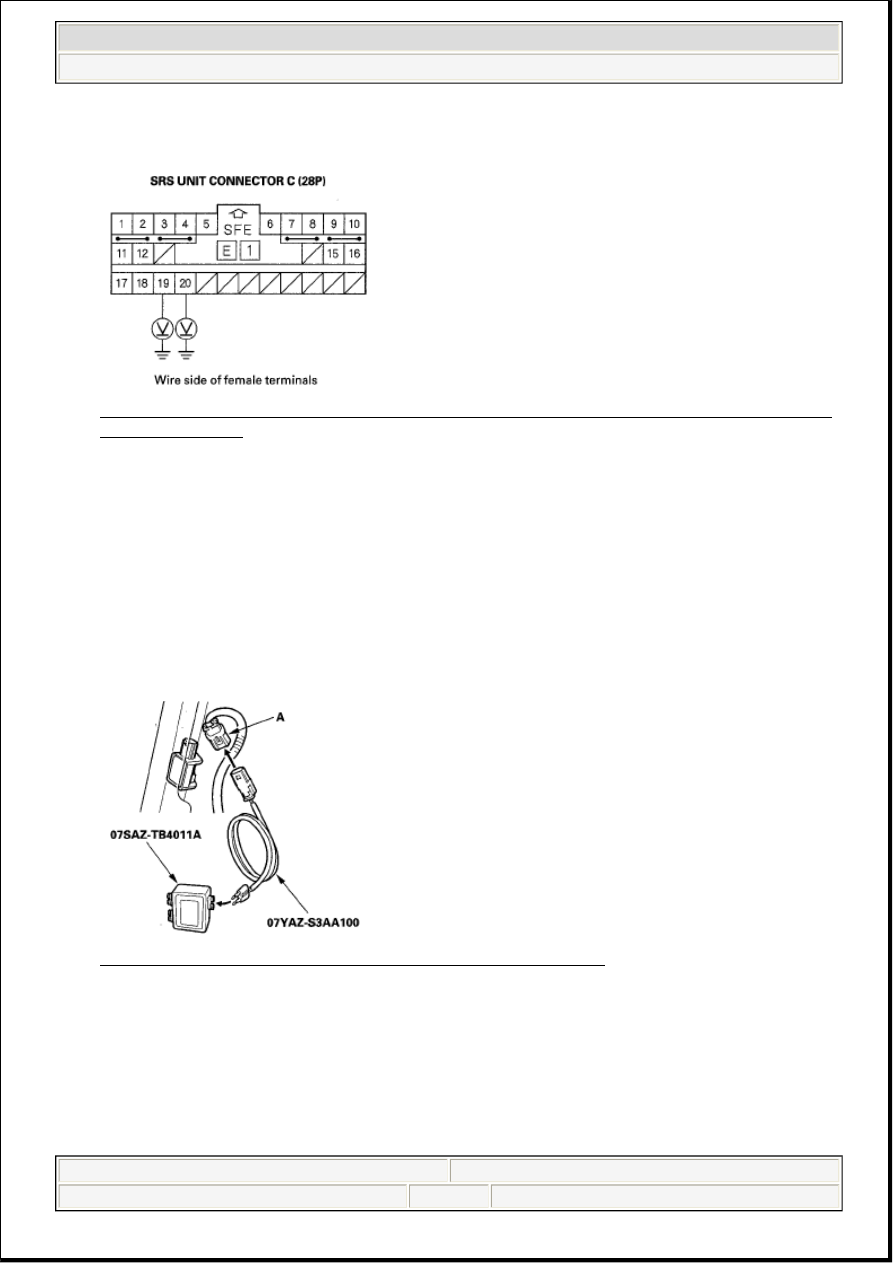
Fig. 262: Measuring Voltage Between No. 19 [No. 20] Terminal Of SRS Unit Connector C (28P)
And Body Ground
Courtesy of AMERICAN HONDA MOTOR CO., INC.
Is the voltage as specified?
YES - Go to step 12.
NO - Short to power in the right side wire harness or left side wire harness; replace the faulty harness.
12. Turn the ignition switch OFF.
13. Connect the SRS inflator simulator (jumper connector) and simulator lead H to the right side wire
harness 2P connector (A).
Fig. 263: Identifying Right Side Impact Sensor And 2P Connector
Courtesy of AMERICAN HONDA MOTOR CO., INC.
14. Measure the resistance between the No. 19 and No. 20 terminals of SRS unit connector C (28P).
There should be 1.0 ohms or less.
2007 Acura RL
2005-08 RESTRAINTS SRS (Supplemental Restraint System) - RL
me
Friday, June 05, 2009 2:21:57 PM
Page 192 © 2005 Mitchell Repair Information Company, LLC.