Lotus Eleven/Elise/Exige. Manual - part 28


  Index      Lotus     Lotus Eleven/Elise/Exige (engine 1ZZ/2ZZ/1ZR) - service repair manual 2004 year


Search            


Content   ..  26  27  28  29   ..


Lotus Eleven/Elise/Exige. Manual - part 28


Page 6


Lotus Service Notes   


    Section DH

DH.3 - SUSPENSION DISASSEMBLY/ASSEMBLY

The suspension may be disassembled without the use of any special tools other than a 'Torx' socket for 

the hub bearing carrier bolts, a spring compressor required only if the spring is to be removed from the damper 

unit, and a ball joint splitter.  If the hub carrier is to be removed, necessitating withdrawal of the driveshaft, it is 

recommended first to release the driveshaft nut before dismantling the brakes. 

With the car on a wheel free lift and with the rear wheels removed:

1.  Remove the split pin securing the driveshaft nut, and with the brakes firmly applied, remove the driveshaft 

nut.

2.  Remove the engine bay undertray to provide access to the lower wishbone front pivot.

3.  Disconnect the parking brake cable from the caliper.  Release the 'P' clip securing the brake hose to the 

top wishbone and remove the two bolts securing the brake caliper to the hub carrier.  Support the caliper 

aside without straining the brake hose.  Release the single retaining screw, and remove the brake disc 

from the hub.

4.  Disconnect the wheel speed sensor cable from each hub unit, and release from routing clips.

5.  Release the nut securing the outer end of the toe link to the hub carrier, and use a ball joint separator to 

release the joint from the carrier.

6.  Remove the nut securing the ball pin of the lower ball joint to the hub carrier, and use a ball joint separator 

to release the joint from the carrier.

7.  Remove the two bolts securing the top swivel joint plinth to the hub carrier, noting and retaining the camber 

adjustment shim pack.

8.  Withdraw the hub carrier assembly from the driveshaft, using a suitable puller tool if necessary to release 

the shaft from the hub.  Do not allow any pulling force to be applied through the driveshaft C.V. joints, or 

damage to the joints will be caused.

9.  Remove the top and bottom mounting bolts for the spring/damper unit, and withdraw.

10.  Remove the top wishbone pivot bolts, and withdraw the wishbone from the rear subframe.

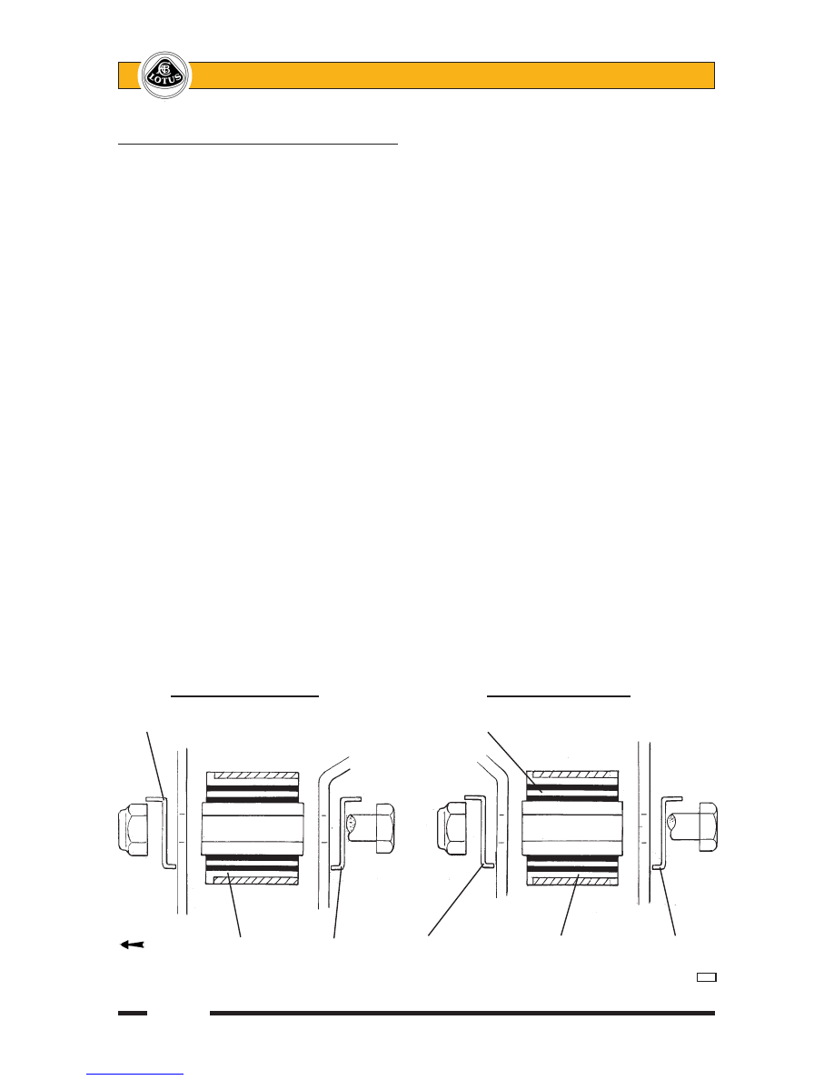
      Top wishbone front pivot                    Top wishbone rear pivot

Tab washer                           Plastic interleaf

     FRONT   Bush inserted    Tab         Tab washer         Bush inserted      Tab

          from front      washer                      from front        washer


d22b 

Page 7


Lotus Service Notes   


    Section DH

      Lower wishbone front pivot              Lower wishbone rear pivot

    FRONT             Pivot mounting          Plastic        Rear        Toe

                    bracket                interleaf       subframe    link

                          Tab                                  ball 

                          washer                                joint


                                                      Anti-rotation 

Weldnut           Short pivot     Flange nut    Long pivot bush       insert           

  bushes                                inserted from front   

 d19b/d


11.  Remove the heatshield over the toe-link inboard ball joint, release the toe-link stud, remove the lower 

wishbone front pivot bolt and withdraw the lower wishbone and toe link.

12.  If necessary, remove the top swivel joint ball pin nut, and use a ball joint splitter tool to separate the joint 

from its plinth.  Either swivel joint may be replaced using suitable press tool dollies.

13.  The wishbone pivot bushes are bonded rubber type with a plastic flanged outer sleeve, a plain steel inner 

sleeve, and a plastic interleaf sleeve within the rubber bush to control the flexing characteristic.  


The bushes may be pressed out of the wishbone eyes, and new bushes fitted using suitable press tool 

dollies.  Smear the outer surface of the new bush with IPC 'P-80' rubber lubricant emulsion (A082C6042V) 

to ease fitment, and assemble as follows:


Top wishbone front pivot - insert a single 30mm long bush from the front end of the eye


Top wishbone rear pivot - insert a single 30mm long bush from the front end of the eye.  Note: Prior to 

January '06 this bush was inserted from the rear end.  Inserting from the front provides greater restistance 

to bush displacement from braking forces.


Lower wishbone rear pivot - insert a single 30mm long bush from the front end of the eye.


Lower wishbone front pivot - insert a 16mm long bush into each end of the front eye.

14.  The road spring may be removed from the damper using a suitable spring compressor to allow the spring 

lower slotted seat to be withdrawn.  Note that the spring upper seat is retained by a square section circlip 

in a groove in the damper body:


- Standard Elise & USA from VIN 3013:  Use centre of 3 grooves for mid-laden ride height of 130mm.

- USA Elise prior VIN 3013:  Use lower of 3 grooves for mid-laden ride height of 135mm.


- Elise with Roadsports suspension package and non-USA Exige:  Use the upper of 2 grooves for mid-

laden ride height of 130mm.


15.  To remove the hub bearing unit from the hub carrier, release the three Torx head bolts and withdraw the 

complete unit.  The hub unit is not serviceable, and is replaced complete if faulty.

Reassembly


Re-assemble the suspension in reverse order to disassembly with the following notes:

Take care to assemble each pivot bolt with the correct washers/snubbers/spacers as shown in the dia-

grams.

Smear the shank of each pivot bolt with PBC grease, but do not allow contamination of the threads.

Take care to refit the original camber adjustment shimpack.

Page 8


Lotus Service Notes   


    Section DH

Top ball joint plinth fixing bolts:


The bolts securing the top ball joint plinth to the hub carrier were upgraded in March '04 at VIN serial number 

1537 (approx.) in order to commonise with motorsport applications.  Earlier type 8.8 grade bolts should 

be tightened to 45 Nm; Later 10.9 grade bolts to 68 Nm.  The bolt grade is stamped around the head of 

the bolt.  The thread of both bolt types should first be treated with Permabond A130 (A912E7033V).  

Lubricate the ends of the damper top eye bush with rubber grease.

Tab washers are used for the bolt head of the lower wishbone forward pivot, and on both  top wishbone 

pivots.  In each case, ensure that one end of the tab washer is folded around the chassis edge, and after 

torque tightening the fixing, form the other end of the washer against the flats of the bolt head or nut.  In 

July '05, the thickness of the tab washer was increased from 1.2mm to 1.5mm.  

If the lower wishbone front pivot brackets have been removed from the chassis, ensure that a spacer 

is fitted on each of the four bolts securing each bracket, in order to allow the required bolt stretch to be 

achieved.

Note that on previous Elise models, there have been several variants of the toe-link inboard ball joint.  The 

correct joint for 2005 model year onwards has a ball pin thread pitch of 1.25mm (vs. 1.5mm).  The flats 

on the ball pin should be aligned with the channel in the subframe hardened insert.  Note that the inboard 

joint has a LH thread into the toe-link tube, and the outboard joint a RH thread into the toe-link tube with 

a taper shank ball pin to fit into the hub carrier.


Left hand bracket viewed from rear

Chassis

Wishbone pivot

bracket                                                Spacer tubes


d44

                                                   This bolt inverted for

                                                    parking brake cable    

                                                    clearance

                                Hardened insert

                                                        Toe-link ball joint

                                             Align ball joint flats

Rear subframe                                     with insert channel

crossmember


 d43

Page 9


Lotus Service Notes   


    Section DH

Do not operate the car without the exhaust silencer heatshielding correctly fitted, and incorporating heat-

shields for the toe-link inboard ball joints.

Press the brake pedal to reposition the pads before driving the car.

If the car suffers a suspension impact sufficient to damage a wheel rim, careful attention should be paid 

to all related suspension components.  Such forces can cause stretching of the lower ball pin and conse-

quent fixing nut torque loss.  As a safety precaution, it is recommended that in all such cases, the lower 

ball joint and the two bolts securing the upper ball joint plinth to the hub carrier are renewed, together with 

both toe-link ball joints.

The Service Schedule specifies that the security of the front and rear suspension is checked at each service.  

For cars used on race tracks, or in similar conditions, suspension components and torque checks should be 

carried out between sessions.  This operation requires that all the principal suspension pivot bolts are torque 

checked, noting the following points:

Where a bolt is tapped into a housing or weldnut, and relies on a thread locking compound for security, be 

aware that if the bolt is disturbed, the locking compound must be re-applied.  The following procedure should 

be adopted for all such fixings:

Check the torque of the fixing.  

If the specified torque is attained without the fixing being disturbed (moving), take no further action.

If the bolt moves, the locking action of the thread adhesive will have been compromised.  Remove the 

bolt completely, clean off all old adhesive using a wire brush and acetone, and apply new adhesive as 

specified.

Refit the bolt and tighten to the specified torque.


If for any reason a bolt is found to have become loose, and the car has been operated for any period in 

this condition, the bolt should be renewed as a standard precaution and related components carefully 

inspected for hole ovality or wear.


At every service interval, the toe-link should be checked for free articulation by using a spanner on the flats 

of the link and twisting in both directions.  The torque required to articulate the joints should be little more 

than may be applied by hand.  If any joint is found to be seized or tight (or if any free play is evident), the 

joint should be renewed.  At each service, the toe-link inboard pivot should be torque checked to allow for 

any settling of the ball joint orientation flats into the galvanised subframe groove.

Torque Settings:                            Nm

Upper and lower wishbone pivot bolts             45

Upper and lower swivel joint ball pins            55

Upper swivel joint plinth to hub carrier  - 8.8 grade    45


                          - 10.9 grade   68

Toe-link outer ball joint to hub carrier             55

Toe-link inner ball joint/wishbone to subframe        60

Toe-link ball joint lock nuts                   45

Damper to lower wishbone                   45

Damper to chassis                        45

Brake caliper to hub carrier  - upper M10         45 - 50


                    - lower M8          26 - 30

Hub bearing unit to hub carrier                90

Rear hub nut                            220

DH.4 - REAR WHEEL BEARINGS

The sealed rear wheel bearings are contained in a steel housing secured to the hub carrier with three 

'Torx' bolts.  The double row, angular contact, ball bearing is retained in the outer housing and also onto the hub 

spigot by a shoulder and a peening operation, and is inseperable for service.  Note that all four hub assemblies 

are common,  and incorporate a wheel speed sensor in the bearing unit, with a flying lead terminating in an 

electrical connector plug secured by a camber shim plate bracket.   

If there is found to be any discernible free play in the hub bearing, or any roughness or tight spots can be 

felt, or any signs of lubricant expulsion are evident, the hub assembly should be replaced - there is no provi-

sion for adjustment.  


Content   ..  26  27  28  29   ..