Porshe 911 (997). Manual - part 48


  Index      Hummer     Porshe 911 997 series - service repair manual 2004-2008 year


Search            


Content   ..  46  47  48  49   ..


Porshe 911 (997). Manual - part 48


–  Primary chain tensioner on crankcase (oil filter area), identification: one ring

-arrow-

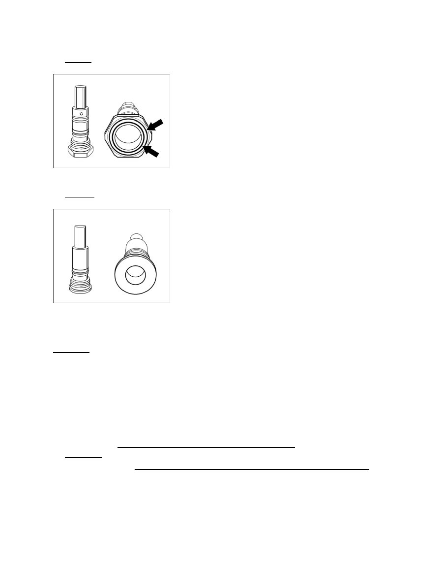
Chain tensioner, cylinders 1 - 3

–  Chain tensioner on cylinder head, cylinder bank 1 - 3, identification: two rings

-arrows-

Chain tensioner 4 - 6

–  Chain tensioner on cylinder head, cylinder bank 4 - 6, no

identification.

Preliminary work for removing camshafts

Preliminary work for removing camshafts

1. Remove engine → 100119 Removing and installing engine - chapter on

"removing".

2. Remove rear muffler → 263319 Removing and installing rear muffler - chapter on "removing".

Diagnostic system: reading out fault memory and activating systems

Allocation of chain tensioners

349

Cover plate and support for rear muffler

3. Remove cover plate for ignition coils -1- . Unscrew two M6 x 16 Torx screws and remove cover plate.

Rear muffler support

4. Remove support for rear muffler. Disconnect cable plugs of ignition coils and magnetic hydraulic

valves. Unscrew four Torx screws: intake side two M8 x 30, exhaust side two M8 x 25, remove
support.

5. For disassembling cylinder bank 4 - 6, undo the ground cable on the cylinder head by unscrewing a Torx

screw M8 and removing the cable. Disconnect two cable plugs from oil pressure switch.

Hydraulic valves for camshaft adjustment and ignition coils

6. Remove ignition coils -1- . In each case unscrew two Torx socket screws M6 x 25 and pull the

ignition coils out of the spark-plug recess.

7. Remove solenoid hydraulic valves -2- (NVS und VHS). → 153719 Removing and installing solenoid

hydraulic valve NVS - chapter on "removing" and → 155519 Removing and installing solenoid hydraulic
valve VHS - chapter on "removing".

Diagnostic system: reading out fault memory and activating systems

Preliminary work for removing camshafts

350

8. Remove spark plugs. → 287020 Removing and installing spark plugs - chapter on

"removing".

Oil suction pump for cylinders 1 - 3

9. Remove oil suction pump for cylinders 1 - 3. Unscrew four Torx screws M6 x 20

(micro-self-locking), remove oil suction pump, and replace O-ring and screws.

Tandem pump side 4 - 6

10. Remove tandem pump for cylinders 4 - 6. Unscrew four Torx screws M6 (micro-self-locking)

-1-

 . Pull off the vacuum line on pump -2- . Remove pump and replace O-rings and

micro-self-locking screws.

Removing camshaft - engine removed

Removing camshafts - engine removed

ATTENTION

Risk of damage due to particles of dirt.

Oil bores/oil ducts can become blocked up.

• 

→ When working on the engine, absolute cleanliness is essential.

→ Lay removed engine parts on a clean base and cover them without fail.

Diagnostic system: reading out fault memory and activating systems

 Removing camshaft - engine removed

351

→ Use the cover for dust protection when fitting the engine NR.165 on the engine assembly support.

1. Remove the plastic caps on the cylinder head. Press a small screwdriver into the centre of the piercing

point of each cap and lever out the cap.

TDC marking on pulley

2. Disassembling cylinder bank 1 - 3 Turn crankshaft at the pulley/vibration balancer clockwise to

the overlapping TDC of cylinder 1. Disassembling cylinder bank 4 -6 Turn crankshaft to the
TDC for cylinder 4. Using a locating pin 9595/1 fix the pulley or vibration balancer .

Position of the camshafts in overlapping TDC of cylinders 1 or 4

3. If the camshafts of cylinder bank 1 - 3 are removed, the smaller circular cut-outs at the grooves of the inlet

and outlet camshafts -arrows- of cylinder 1 must point to the cylinder head cover. For cylinder bank 4-6
the corresponding position is then on cylinder 4. Check the position using the adjusting gauge 9686.

Unscrew the central screw on the camshaft adjuster.

Note

Before disassembling the cylinder head cover, it is essential to unscrew the central screw on the
camshaft adjustment device.

• 

Diagnostic system: reading out fault memory and activating systems

Removing camshafts - engine removed

352


Content   ..  46  47  48  49   ..