Porshe 911 (997). Manual - part 33


  Index      Hummer     Porshe 911 997 series - service repair manual 2004-2008 year


Search            


Content   ..  31  32  33  34   ..


Porshe 911 (997). Manual - part 33


6

Thrust-bearing screw,

M9 x 127

14

Tightening torque

[Nm] (ftlb.)

7

Gear carrier half,

cylinder 1-3

1

8

Crankshaft

1

9

Thrust washer

2

Position correctly, oil

grooves always point

outwards

10

Gear carrier half,

cylinder 4-6

1

11

Connecting rods,

cylinder 4-6

3

Immediately join with the associated

connecting rod cap after removal

1. Fasten the special tool retaining device 9607 onto the workbench using two screw

clamps.

2. Mark connecting rod 4-6 in the installation position.
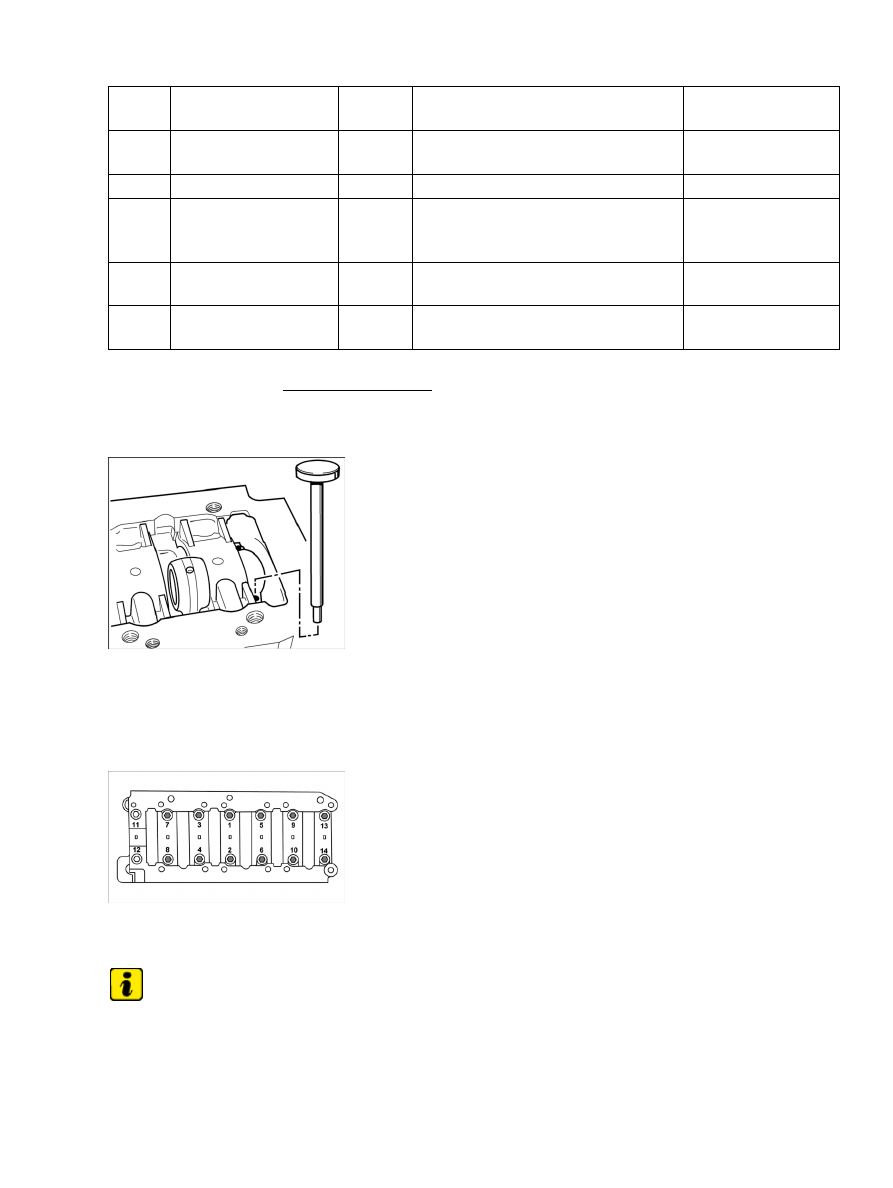
Plastic mandrel

3. Remove connecting rods on cylinder side 4-6 one after another. Loosen the two connecting rod

bolts on each connecting rod, remove connecting rod cap. Using a plastic mandrel (possibly an
in-house tool) push connecting rod down and out. Immediately after this, screw on loosely to
associated connecting rod cap. Place on a clean surface.

Gear carrier

4. Loosen 14 M9 x 127 screws for the gear carrier in the opposite order to the tightening sequence,

from the outside inwards, and unscrew them.

Note

Watch out for bearing shells and oil spray jets that may fall out

5. Remove gear carrier half 1-3, possibly tapping it gently with a plastic hammer.

Diagnostic system: reading out fault memory and activating systems

Removing crankshaft

289

Oil spray jets in gear carrier half 1-3

6. Place gear carrier half on a clean surface, remove seven crankshaft bearing shells and three oil spray jets

for piston cooling.

7. Lever out crankshaft with timing chain and place on a soft, clean surface.

8. Remove seven crankshaft bearing shells and oil spray jets for piston cooling from gearing carrier half 4-6.

Unscrew gear carrier half from the retaining device and place on a clean surface.

Installing crankshaft

Installing crankshaft

Connecting rod bearing position in gear carrier

Overview of connecting rod bearing position

Gear carrier half 4-6 on device

Diagnostic system: reading out fault memory and activating systems

 Installing crankshaft

290

1. Fit gearing carrier half 4-6 on special tool retaining device 9607 using two M10 x 25 hexagon-head bolts.

Dowel sleeves, gear carrier 4-6

2. Ensure that the dowel sleeves are seated correctly in gear carrier half

4-6.

Oil spray jets for piston cooling

3. Insert three oil spray jets in the take-up bores in each of the gear carrier halves, press in gently to the

stop using a plastic mandrel (ø 4 mm).

Thrust washer, thrust block

4. Insert two thrust washers onto the centre thrust block (no. 4) of gear carrier half 4-6; when doing so,

the oil pockets -arrows- must always point outwards (to the belt pulley side or flywheel side).

Diagnostic system: reading out fault memory and activating systems

Installing crankshaft

291

Oil spray jets and bearing shells in gear carrier half 1-3

5. Insert seven new bearing shells for the crankshaft and coat with new engine oil. Pay attention to

the installation position:

 the fixing lugs of the bearing shells in gear carrier half 4-6 point towards

the dowel sleeve side, the fixing lugs of the bearing shells in gear carrier half 1-3 face the opposite
side.

Twist lock of bearing shell in gear carrier half 4-6

Twist lock of bearing shell

Seating of thrust washer with crankshaft

6. Insert crankshaft. Check that the thrust washers are seated

properly.

7. Carefully position gear carrier half 1-3 on the crankshaft and gear carrier half 4-6. Fix the gear carrier

halves by tapping them carefully with a plastic hammer.

Diagnostic system: reading out fault memory and activating systems

Installing crankshaft

292


Content   ..  31  32  33  34   ..