Engine International VT365. Manual - part 9


  Index      International     Engine International VT365 - service repair manual 2006 year


Search            


Content   ..  7  8  9  10   ..


Engine International VT365. Manual - part 9


ENGINE SYSTEMS

33

Lubrication System

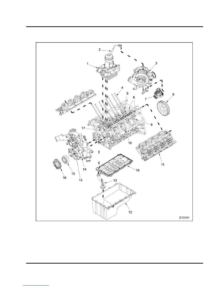
Figure 27 Lubrication system

1.

Oil cooler cover with filter base

2.

VGT oil supply line

3.

VGT

4.

Push rod (16)

5.

Valve lifter (16)

6.

Main lube oil gallery (2)

7.

High-pressure oil pump
assembly

8.

Camshaft gear

9.

Piston cooling tube (8)

10. Main bearing insert (10)
11. Cylinder head (2)
12. Lower oil pan

13. Oil pick up tube
14. Front cover housing
15. Gerotor assembly
16. Gerotor housing cover
17. Cam bushing (5)
18. Oil regulator valve
19. Upper oil pan

34

ENGINE SYSTEMS

Oil Flow

Figure 28 Lubrication system schematic

The lubrication system is pressure regulated, cooled,
and full flow filtered.

Oil is drawn from the oil pan through the pickup tube,
upper oil pan, lower crankcase, and the front cover to
the gerotor oil pump.

The gerotor oil pump includes the front cover
assembly, gerotor assembly (inner and outer gears),
and the gerotor housing cover. The crankshaft drives
the inner rotor gear of the gerotor pump.

The gerotor pump pressurizes lube oil. Pressurized
lube oil flows from the front cover through a passage
in the lower crankcase.

Lube oil from the lower

crankcase flows through a passage in the upper
crankcase to the oil cooler base. Passages in the oil
cooler base direct lube oil and coolant.

ENGINE SYSTEMS

35

Figure 29

Oil cooler base and oil filter base

1.

VGT oil supply tube assembly

2.

Oil filter housing

3.

Oil filter base assembly

4.

Oil cooler cover

Lube oil is routed from the front of the oil cooler cover
to the back where it enters the oil cooler. Lube oil is
cooled as it flows from the back of the oil cooler to the
front into the oil filter housing.

If the oil cooler is restricted, a bypass valve in the
oil filter base will open and allow oil to bypass the
oil cooler going directly to the oil filter housing.

Oil flows to the oil filter element. Oil passes through
the outside of the element to the inside of the element,
down the stand pipe, back into the oil filter base, and
into the oil cooler base.

The oil filter base directs filtered oil in four ways:

One passage supplies filtered oil to the oil
temperature sensor, oil pressure sensor, oil
supply tube for the VGT, and oil supply for the air
compressor (optional).

Figure 30 Oil reservoir in crankcase

1.

Oil feed to high pressure pump

2.

Oil filter drain to pan

3.

Oil feed to oil cooler cover

4.

Oil feed to left side of main lube oil gallery

5.

Oil feed to right side of main lube oil gallery

6.

Coolant feed to oil cooler

A second passage supplies filtered oil to the
reservoir in the crankcase for the high pressure
pump and ICP system.

Two other passages supply filtered oil for the
following:

Left side

Main lube oil gallery

Push rod and rocker arms

Piston cooling tubes

Right Side

Main lube oil gallery

Push rod and rocker arms

Piston cooling tubes

36

ENGINE SYSTEMS

Cam bushings

Crankshaft main bearings

Connecting rod bearings

When the oil filter is removed, oil flows from a drain
valve in the oil filter base back to the oil pan.


Content   ..  7  8  9  10   ..