Lifan LF125-26C. Service manual (2024)
FOREWORD
This manual covers the structure, operation, inspection, maintenance and repair of LF125-26C(Euro V) for use by the LIFAN dealers and qualified mechanics.
With both the descriptions and figures/drawings, you may have a comprehensive understanding of the structure as well as service and repair skill.
Lifan Technology (group) Co., Ltd. is continually striving to improve all its models. All information in this publication is based on the latest product information
available at the time of printing. LIFAN reserves the right to make changes at any time without notice and without incurring any obligation.
No part of this publication may be reproduced without written permission.
LIFAN TECHNOLOGY (GROUP) CO., LTD.
Jan, 2024
CONTENT
CHAPTER 1 GENERAL
1.1 VEHICLE INTRODUCTION……………………………
1-1
1.2 SPECIFICATIONS………………………………………
1-2
CHAPTER 2 ENGINE
2.1 CYLINDER HEAD
2-1
2.2 CYLINDER BLOCK………………………..…………………………
2-10
2.3 VALVE TRAIN……………………………………………………………
2-16
2.4 CRANKCASE……………………………………………
2-26
2.5 TRANSMISSION………………………………………
2-33
2.6 CRANK MECHANISM ………………………………………………
……
2-50
2.7 STARTER..…………………………………………………
2-57
2.8 LUBRICATION SYSTEM……………………………………………
2-64
CHAPTER 3 CHASSIS
3.1 FRAME BODY
3-1
3.2 SUSPENSION SYSTEM
3-6
3.3 FRONT SUSPENSION
3-10
3.4 REAR SUSPENSION
3-14
3.5 FRONT AND REAR WHEELS
3-16
3.6 INTAKE SYSTEM AND EXHAUST SYSTEM
3-21
CHAPTER 4 ELECTRICAL COMPONENTS AND METER
4.1 CHARGING SYSTEM
4-4
4.2 IGNITION SYSTEM
4-7
4.3 SIGNAL SYSTEM AND METER
……4-11
4.4 LIGHTING SYSTEM
4-16
4.5 ELECTRIC STARTING SYSTEM
4-18
4.6 BATTERY AND FUSE
4-21
4.7 LIGHTS AND HORN
4-23
CHAPTER 5 CONSTRUCTION AND MAINTENANCE OF EFI SYSTEM
5.1 INTRODUCTION OF EFI SYSTEM
5-1
5.2 CONFIGURATION AND LAYOUT OF EFI PARTS
5-2
5.3 EFI PERFORMANCE AND MALFUNCTION
5-4
5.4 MALFUCNTION DIAGNOSIS
5-11
5.5 TROUBLESHOOTING
5-14
CHAPTER 6 SERVICE
6.1 ROUTINE MAINTENANCE AND ADJUSTMENT
6-1
6.2 PRE-RIDE INSPECTION
6-3
6.3 GENERAL MAINTENANCE
6-3
6.4 STORAGE
6-5
6.5 UNPACKING
6-5
CHAPTER 1 GENERAL
1.1 Vehicle Introduction
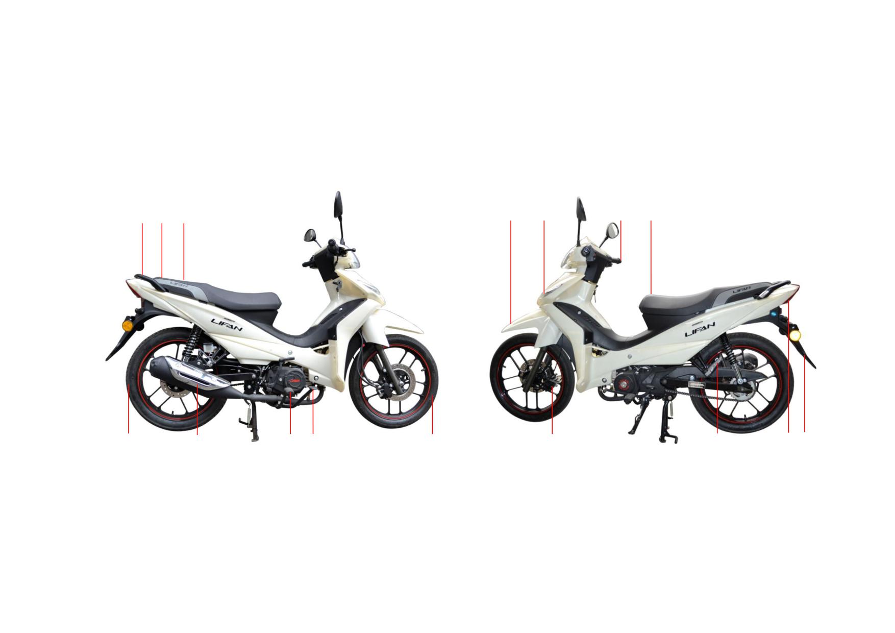
LF125-26C (Euro V) two-wheeled motorcycle, with beautiful and novel appearance, compact structure, bright colors, and smooth lines, brings people a strong visual
impact. The large built-in inner trunk better meets the practical needs of users, further highlighting the beauty and practicality of the whole vehicle with full of charm.
The vehicle is equipped with Lifan's self-developed horizontal engine of 1P53FMI with single cylinder, air cooler, 4 stroke, high-performance automatic dual clutch,
wet multi-plate clutch, electric/kick start and four-speed transmission, which has greater power and torque than engines of the same displacement. In addition, the
vehicle is equipped with front and rear disc brakes and hydraulic spring damping shock absorbers, which maximizes the user's riding safety, comfort, and other needs.
①
②
③
④
⑥
⑦
⑧
⑤
④
③ ②
①
⑧
⑦
⑥
⑤
①Front wheel ②Rear brake pedal ③Front footrest ④Exhaust muffler
①Front fender ②Headlight ③Steering bar ④Fuel tank ⑤Rear fender
⑤Rear wheel ⑥Handrail ⑦VIN ⑧Seat
⑥Taillight ⑦Rear footrest ⑧Front hydraulic brake
1-1
1.2 Specifications
ITEM
SPECIFICATIONS
Length×Width×Height
1960mm×715mm×1110mm
Wheelbase
1245mm
Dimension and
Ground clearance
130mm
Weight
Kerb mass
177kg
Max. weight capacity
150kg
Model
1P53FMI
Type
Horizontal single cylinder, air-cooled, 4 stroke, auto dual clutch, electric/kick start
Bore × stroke
53.5 mm×55.5mm
Displacement
124.7 cm3
Compression ratio
10.5:1
Engine
Air cleaner
Plastic housing with paper element
Lubrication
Press/splash
Starting mode
Electric/kick start
Max. net power
6.7kW/8000r/min
Max. torque
9.0N·m/6000r/min
Idle speed
1500±100 r/min
Front shock absorber
Hydraulic telescopic damping type
Rear shock absorber
Hydraulic telescopic damping type
Steering bar angle
≤42°
Driving system
Front
2.50-17-4PR/200kPa
Tyre size/pressure
Rear
2.75-17-4PR/225kPa
Drive mode
Chain
Turning circle diameter
4060mm
1-2
Clutch
Wet, multi-plate type
Transmission
4-speed, constant mesh
Primary reduction
4.059
Final reduction
2.571
1st
2.833
Drive Train
2nd
1.706
Gear ratio
3rd
1.238
4th
0.958
Drive chain
Model
08MB
Link No.
106
Front
disc brake
Braking system
Rear
disc brake
Ignition
ECU
Ignition advance angle
0-40°
Spark plug
CPR8EA
Spark plug gap
0.8-0.9mm
Battery
12V6Ah
Fuse
15A
Electrical system
Headlight
HS1/12V35W
Front position light
LED
Tail/brake light
LED
Winker
LED
Turn signal indicator
LED
High beam indicator
LED
Gearshift indicator
LED
1-3
Meter backlight
LED
Fuel type
RQ-92
Capacity
3.0L
Fuel tank
Reserve
0.7L
Fuel/Oil
Engine oil
Type
SF 15W/40
Capacity
0.9L
Type
HQ-10
Damping oil
Capacity
(60±1)mL
1-4
CHAPTER 2 ENGINE
2.1 CYLINDER HEAD
2.1.1 Removal, Maintenance and Installation
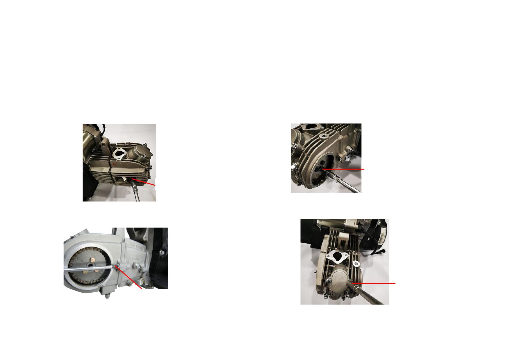
1) Unscrew the left cover bolt M6 from the cylinder head and remove the cover.
3) Unscrew the timing bolt M5 and timing driven sprocket.
Tightening torque: 8~12N
m
Tightening torque: 6~10N
m
TIGHTENING BOLT M5
BOLT M6
4) Unscrew the valve cover bolt M6 to remove the cover.
2) Unscrew the cylinder head connecting bolt M6.
Tightening torque: 8~12N
m
Tightening torque: 8~12N
m
BOLT M6
CONNECTING BOLT M6
2-1
2.2 CYLINDER BLOCK
2.2.1 Removal, Maintenance and Installation
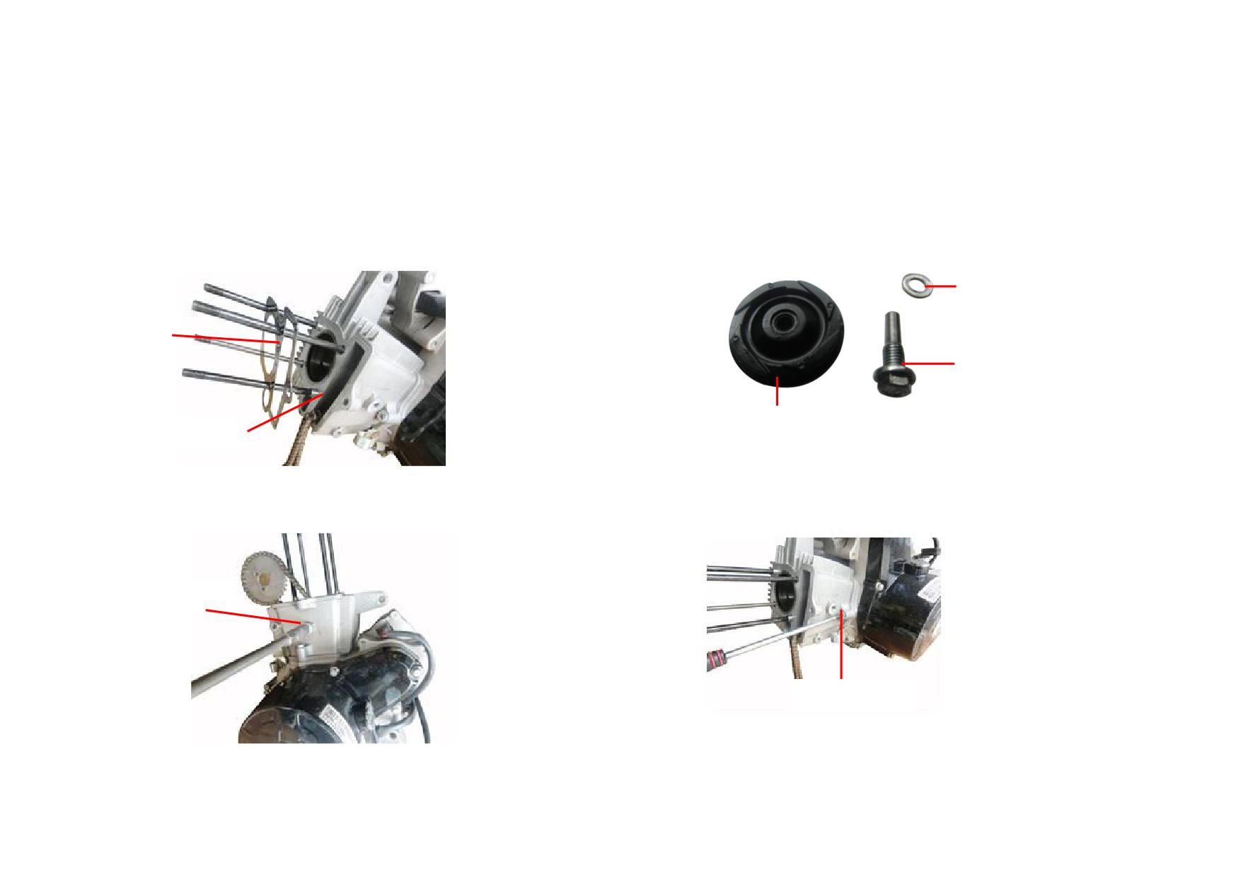
1) Remove and check the cylinder head gasket and dowel pin for damage,
3) Check the guide pulley for wear, replace it if necessary.
replace them if necessary.
GUIDE PULLEY
PIN WASHER
GASKET
GUIDE PULLEY PIN
GUIDE PULLEY
DOWEL PIN
2) Remove the guide pulley pin M6 and guide pulley.
4) Remove the connecting bolt M6 of cylinder block.
Tightening torque: 8~12N
m
Tightening torque: 8~12N
m
GUIDE PULLEY PIN
CONNECTING BOLT
2-10
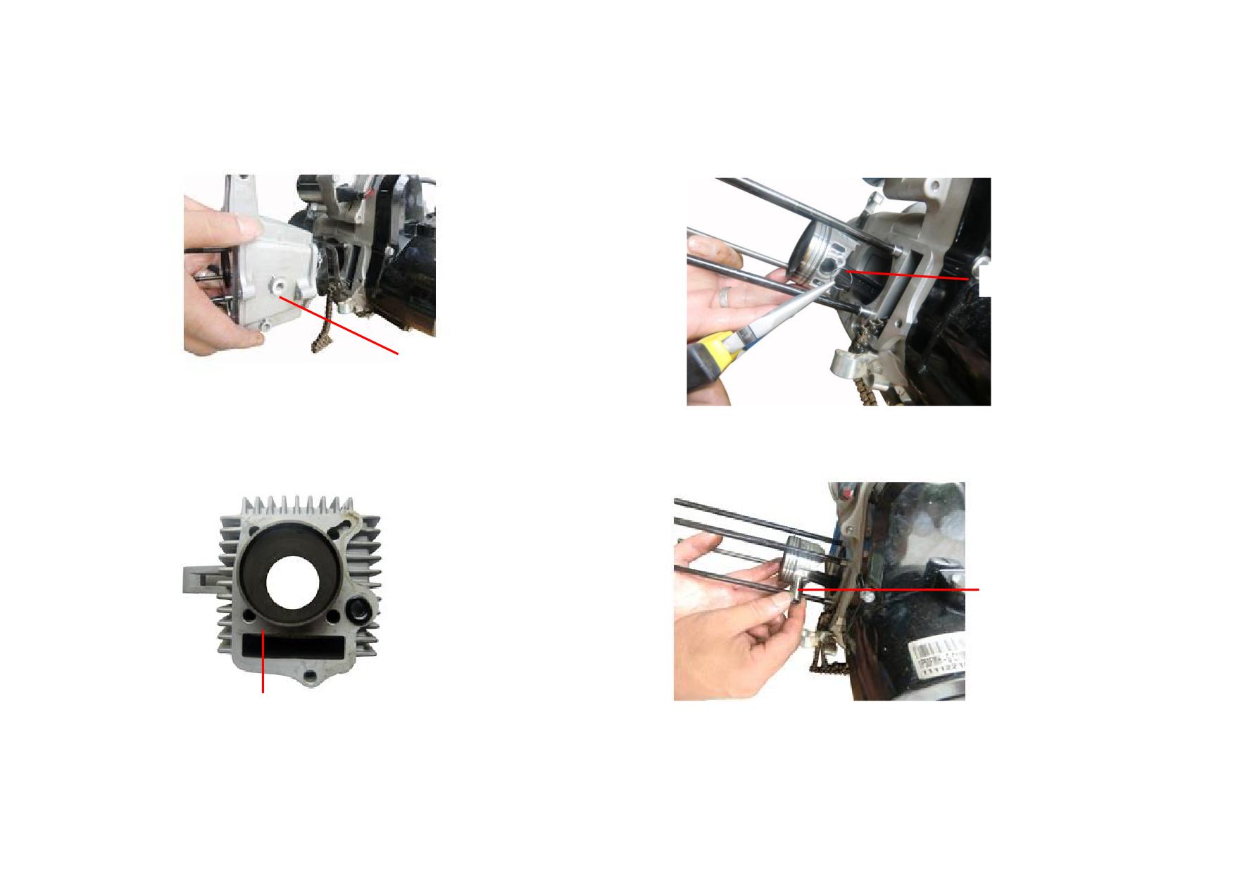
5) Remove the cylinder block.
7) Remove the piston pin circlip. (Attention! Dot not fall the circlip into the
crankcase).
PISTON PIN CIRCLIP
CYLINDER BLOCK
6) Measure the cylinder wall, replace the cylinder if it exceeds the service limit
8) Pull out the piston pin and check it for wear, replace it if it is out of the
(Φ53.6mm).
service limit (Φ12.978mm).
PISTON PIN
CYLINDER BLOCK
2-11
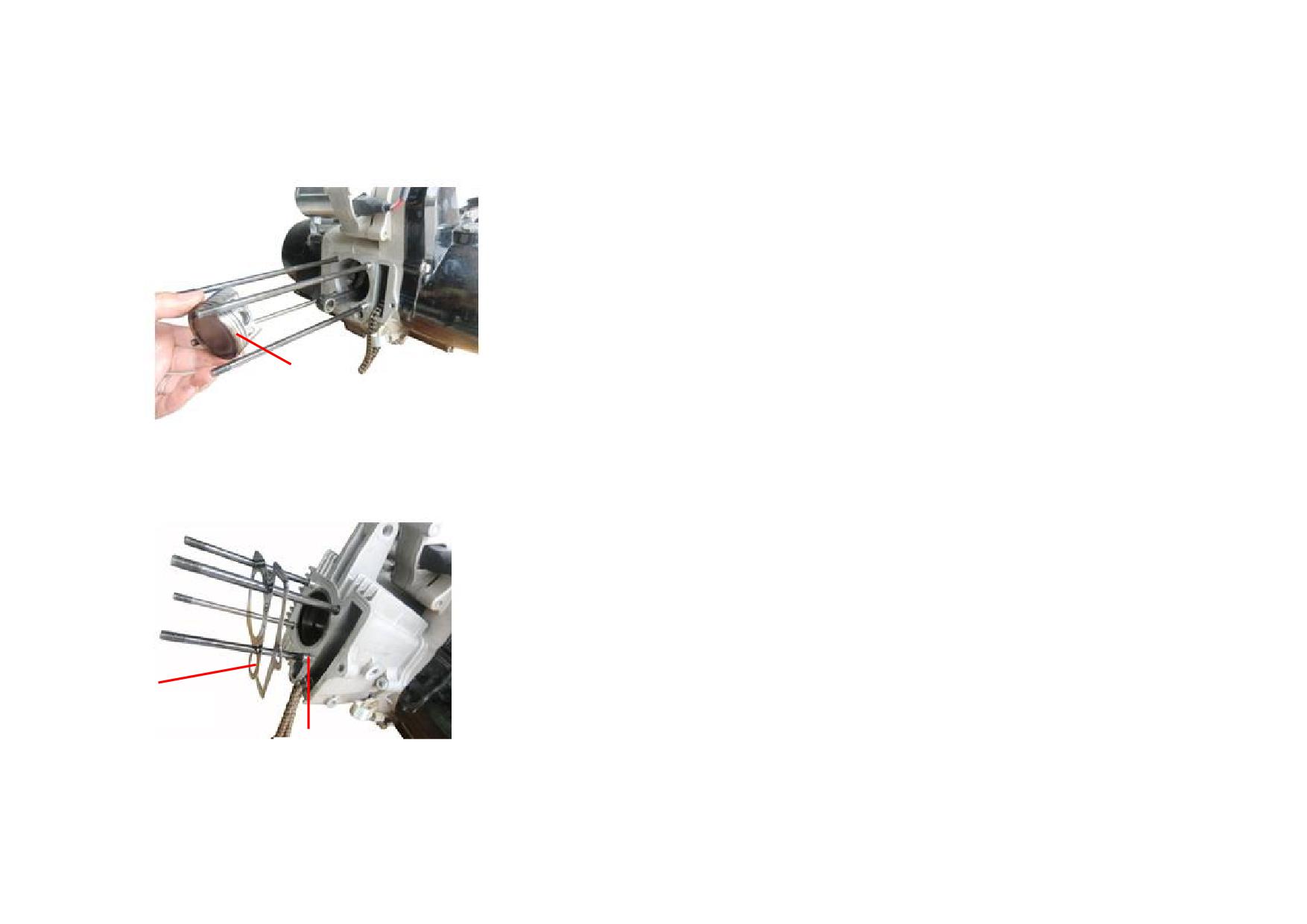
9) Remove the piston and set aside after cleaning it with kerosene.
PISTON
10) Remove and check the cylinder block gasket for damage, replace it if
necessary.
GASKET
DOWEL PIN
2-12
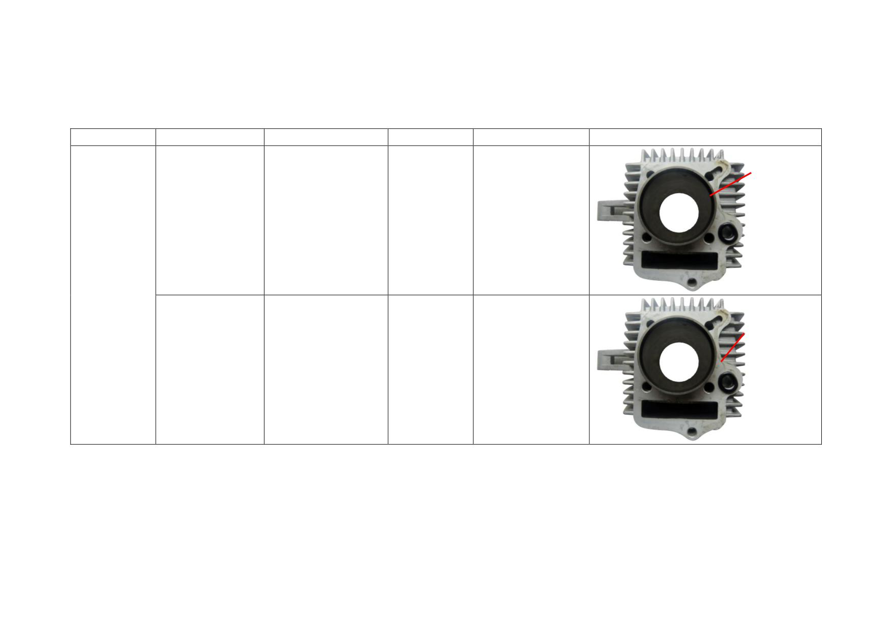
2.2.2 Troubleshooting to Cylinder Block
Description
Damage Form
Trouble
Service
Too much oil dirt and dusts on
Poor cooling and overheating engine
Clear away oil dirt and dusts
the radiating fins
Seriously deformation of upper
Air leaks between cylinder head and cylinder block. Engine fails
Grind the end face of cylinder head or
end face of cylinder block
or is hard to start. Engine lacks power, has unstable idle speed.
replace the cylinder head
Cylinder Block
Large gap of cylinder block and piston, cylinder block and piston
Seriously wear of cylinder
rings. Engine fails or is hard to start. Engine lacks power, has
Repair by a cylinder boring machine or
block
unstable idle speed. Blue or white smoke comes from the exhaust
replace with a new cylinder
pipe.
Broken cylinder block gasket
Oil leaks between cylinder block and crankcase.
Replace the gasket
2-13
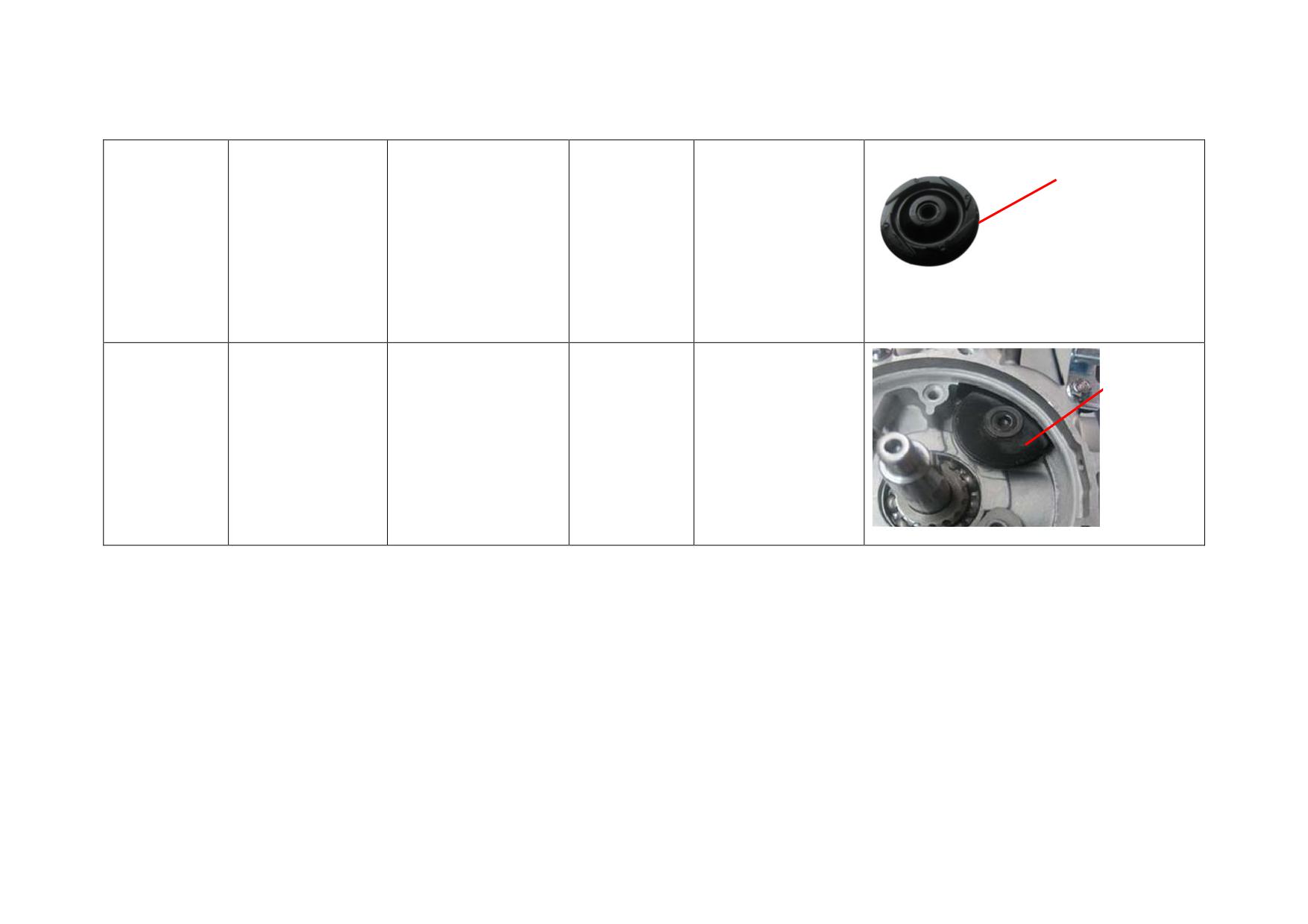
2.2.3 Reference List of Standard Value and Limit Value for Cylinder Block Maintenance
Description
Test Item
Standard Value
Limit Value
Service
Picture
Cylinder
block bore
ID
Replace when beyond
Bore ID
Φ53.5~Φ53.51
Φ53.6
the limit value
Cylinder Block
Flatness on
upper &
lower faces
of cylinder
Replace when beyond
Flatness
0.05
0.08
block
the limit value
2-14
Guide pulley
diameter
Replace when beyond
Guide Pulley
Diameter
Φ45
Φ44
the limit value
Roller
diameter
Replace when beyond
Roller
Diameter
Φ47
Φ46
the limit value
2-15
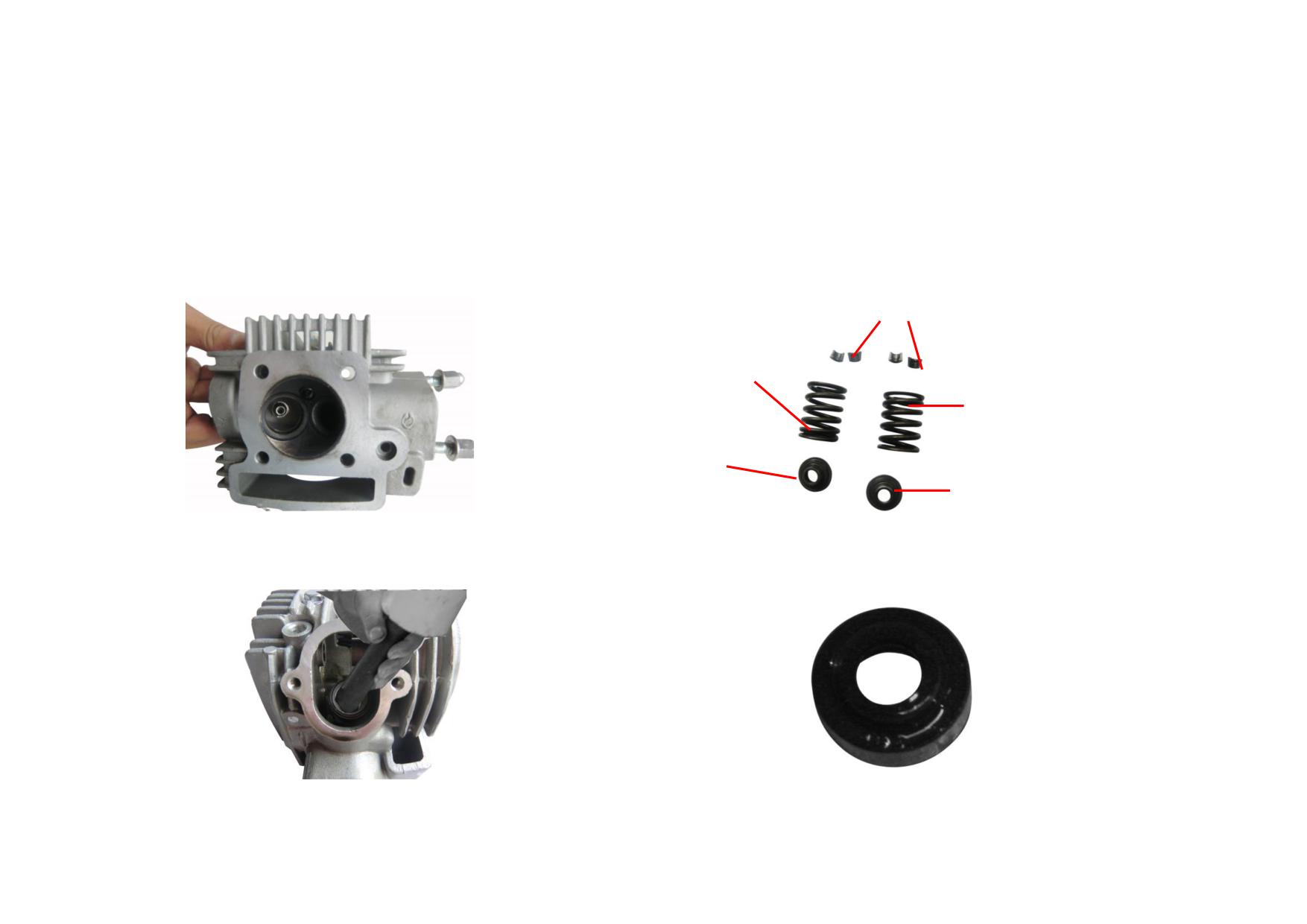
2.3 VALVE TRAIN
2.3.1 Removal, Installation and Maintenance
1) Check the intake & exhaust valves for air leakage, grind the sealing face of
3) Remove and check the valve springs for deformation and wear, replace the
valves if necessary.
spring if it is worn or out of elasticity.
VALVE CLIP
VALVE SPRING
VALVE SPRING
VALVE
SPRING SEAT
VALVE
SPRING SEAT
2) Remove and check the valve clip, valve spring upper seat for wear, repair or
4) Remove and check the oil shield for wear and damage, replace it if necessary.
replace them if necessary.
2-16
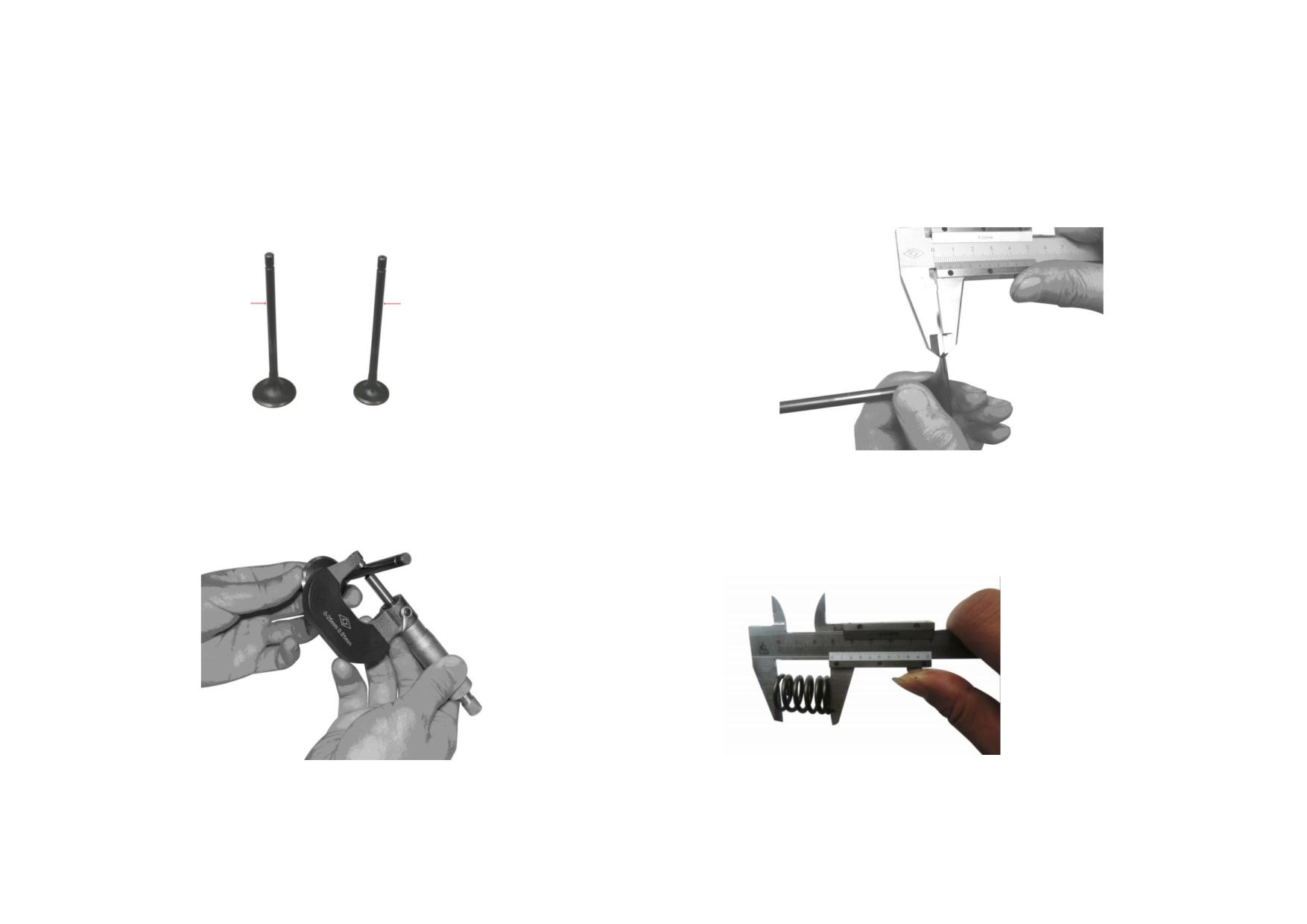
5) Remove and check the intake & exhaust valves for wear, replace them if
7) Measure the valve cone, replace it if values are beyond the service limit
necessary.
(upper valve zone: 32
, lower valve zone: 60
, valve seat face: 45°, valve
margin width: 1.6mm).
Exhaust valve
Intake valve
6) Measure the diameter of valve stem, replace the valve stem if it is beyond the
service limit (intake valve<Φ4.950mm, exhaust valve<Φ4.950mm).
8) Measure the free length of valve spring, replace it if it is beyond the service
limit (<27.7mm).
NOTE: The dense coils face upward when installing the spring.
2-17
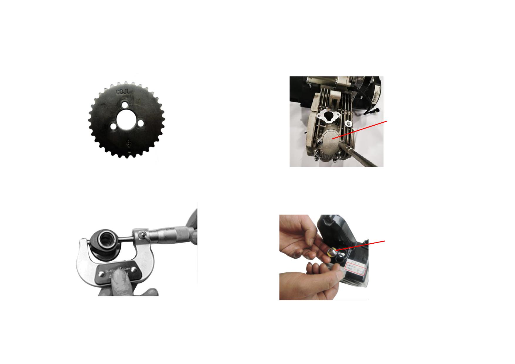
9) Check the timing driven sprocket for wear, replace it if necessary.
11) To adjust the valve clearance, unscrew the valve cover firstly.
Tightening torque: 8~12N
m
VALVE COVER
10) Measure the cam lobe length by means of a micrometer, replace it if it is out
12) Unscrew the plug and view-hole plug from the engine left cover.
of the service limit (intake cam<32.15mm, exhaust cam<31.94mm).
Counterclockwise rotate the magneto rotor until “T” mark on it aligns with the
sign of left crankcase cover, while both the intake and exhaust valves are closed.
Tightening torque: 8~12N
m
VIEW-HOLE PLUG
2-18
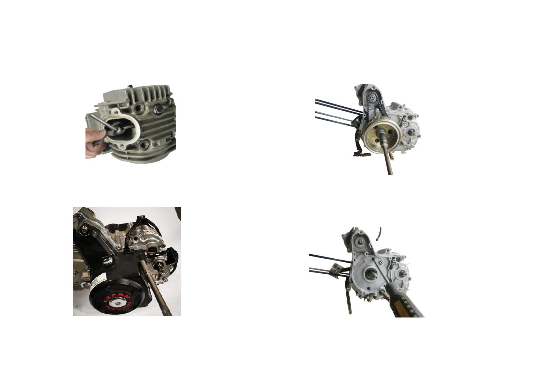
13) Adjust the clearance of intake & exhaust valves to 0.03~0.06mm, tighten up
15) Unscrew the nut of magneto rotor to pull out the rotor.
the adjusting nut. Tightening torque: 6~10N
m
Tightening torque: 40~50N
m
14) Unscrew the bolt to remove the left crankcase cover.
Tightening torque: 8~12N
m
16) Unscrew the plate cover bolt to remove the starting chain, tensioning plate,
guide plate and starting clutch sprocket weldment, and then remove the plate
cover and seal ring. Tightening torque: 8~12N
m
2-19
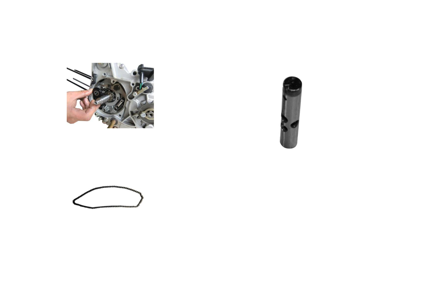
17) Remove and check the tensioning wheel for wear, replace it if necessary.
19) Remove the tensioning rod and check its head for wear, replace it if its OD
exceeds service limit Φ11.94mm.
18) Remove the timing chain, check its stretch and wear, replace it if necessary.
2-20
2.3.2 Troubleshooting to Valve Train
Description
Damage Form
Trouble
Service
Not smooth gas inlet and outlet. Engine lacks power. Large noises from
Excessive wear of cam
Replace the cam
valve train
Valve Train
Excessive wear of camshaft
Hole-to-shaft clearance is too large. Abnormal sound from cam
Replace the camshaft
Timing Chain
Loose
Timing chain is elongated and running with knocking sound
Replace the timing chain
Working surface is scratched or
Abnormal sound from rocker arm, engine lacks power
Replace the rocker arm
seriously worn
Rocker Arm
Rocker arm hole is worn
Abnormal sound from rocker arm, engine lacks power
Replace the rocker arm
Rocker arm shaft is worn
Abnormal sound from rocker arm, engine lacks power
Replace the rocker arm shaft
Engine fails or is hard to start. Engine lacks power and has unstable idle
Adjust the valve clearance to
Little valve clearance
speed.
0.03~0.06mm
Adjust the valve clearance to
Large valve clearance
Knocking sound
0.03~0.06mm
Too much carbon deposits on the
Engine fails or is hard to start. Engine lacks power and has unstable idle
Clear away carbon deposits
Valve
surface
speed.
and grind the valve
Working surface is seriously worn or
Engine fails or is hard to start. Engine lacks power and has unstable idle
Clear away carbon deposits
has pits
speed.
and grind the valve
Valve stem is seriously worn
Thick blue smoke from exhaust pipe
Replace the valve
Valve stem is deformed
Engine fails to start.
Replace the valve
Valve Spring
Spring is broken
Engine fails or is hard to start. Noises from cylinder head
Replace the valve spring
2-21
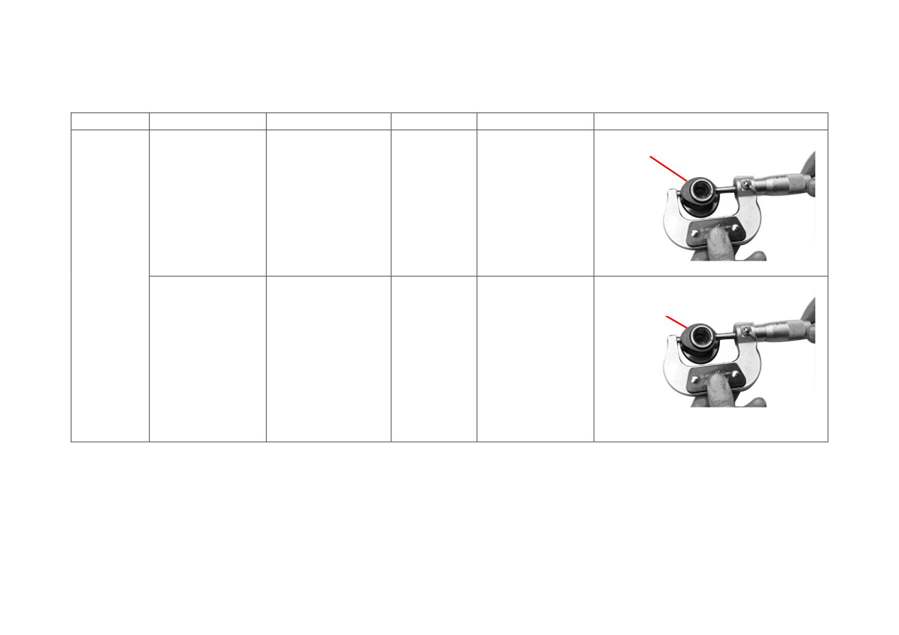
2.3.3 Reference List of Standard Value and Limit Value for Valve Train Maintenance
Description
Test Item
Standard Value
Limit Value
Service
Picture
Height of intake
valve lobe
Height of intake valve
Replace when beyond
32.25~32.37
32.15
lobe
the limit value
Camshaft
Height of exhaust
Assembly
valve lobe
Height of exhaust
Replace when beyond
32.04~32.16
31.94
valve lobe
the limit value
2-22
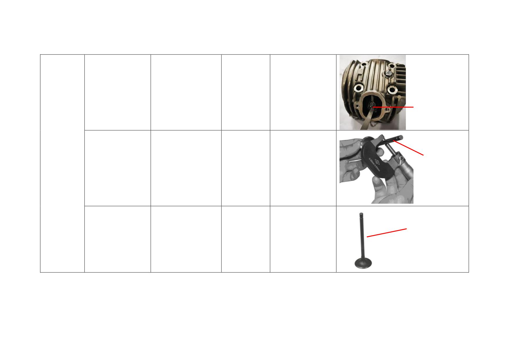
Adjust valve clearance
Intake valve clearance
0.03~0.06
0.10
when beyond the limit
value
Valve clearance
Diameter of
Intake Valve
Diameter of intake
Replace when beyond
intake valve
Φ4.975~Φ4.99
Φ4.950
valve
the limit value
Diameter
Replace when beyond
Runout of valve stem
0~0.01
0.03
the limit value
2-23
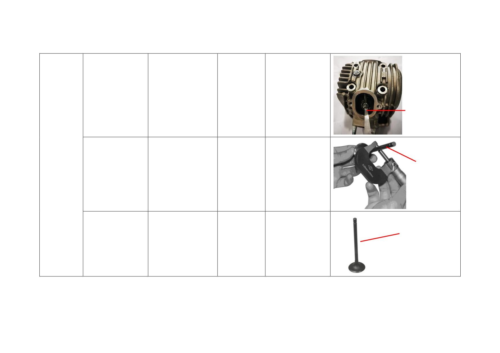
Adjust valve clearance
Exhaust valve
0.03~0.06
0.10
when beyond the limit
clearance
value
Valve clearance
Exhaust Valve
Diameter of
Diameter of exhaust
Replace when beyond
Φ4.955~Φ4.97
Φ4.915
exhaust valve
valve
the limit value
Diameter
Replace when beyond
Runout of valve stem
0~0.01
0.03
the limit value
2-24
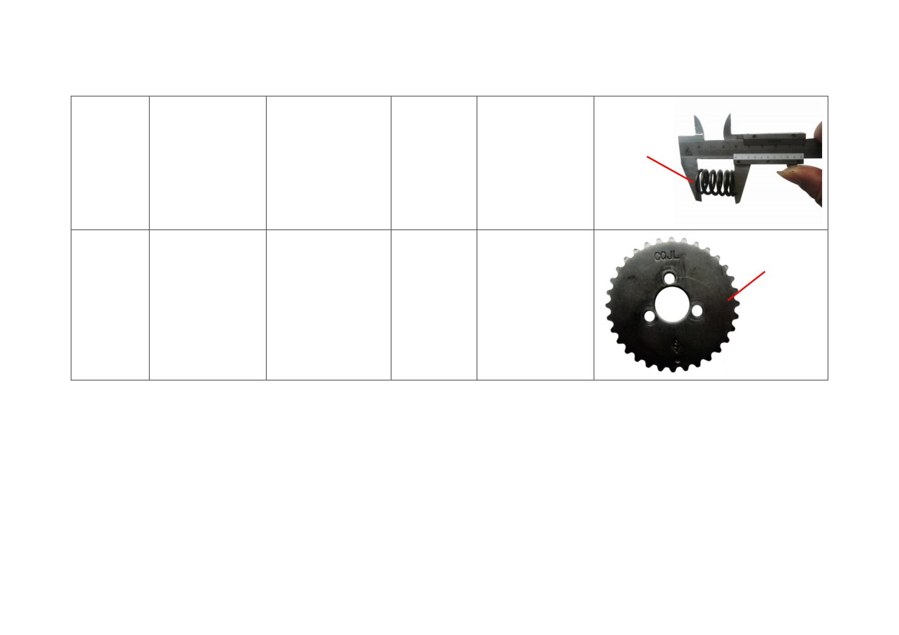
Free height
Replace when beyond
Valve Spring
Free height
29.7~30.7
27.7
the limit value
Diameter of
addendum circle
Timing Driven
Diameter of addendum
Replace when beyond
Φ67~Φ67.6
Φ66.5
Sprocket
circle
the limit value
2-25
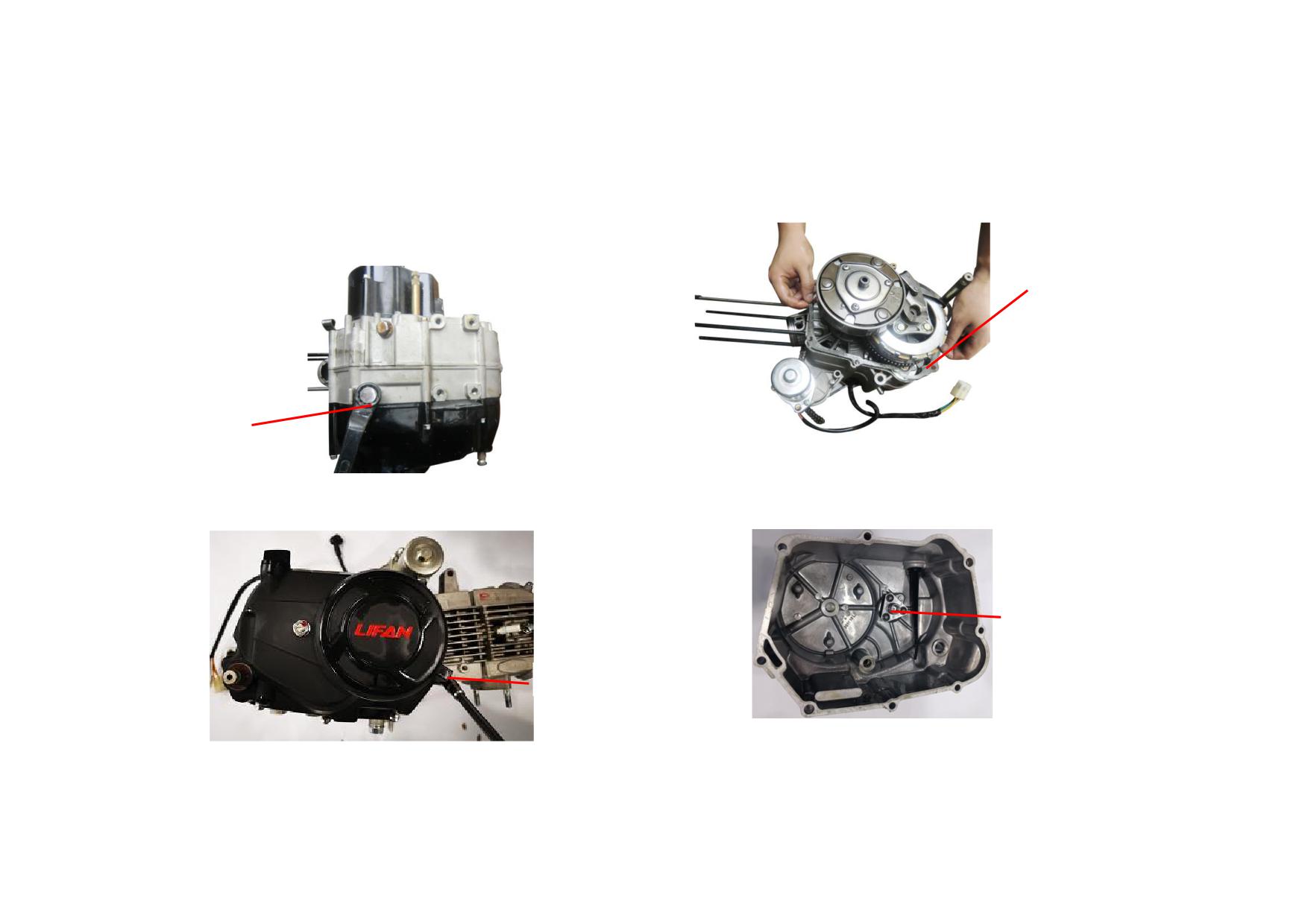
2.4 CRANKCASE
2.4.1 Removal, Maintenance and Installation
3) Check the right crankcase cover gasket for damage, replace it if necessary.
1) Unscrew the drain bolt to empty the engine oil thoroughly.
Tightening torque: 20~30N
m
GASKET
DRAIN BOLT
2) Unscrew the tightening bolt M6 from right crankcase cover, slightly tap the
4) Configuration of right crankcase cover assembly is shown as follows. Check
cover with a rubber hammer to remove it. Tightening torque: 8~12N
m
the clutch separating rod for wear, replace it if necessary.
CLUTCH SEPARATING ROD
TIGHTENING BOLT
2-26
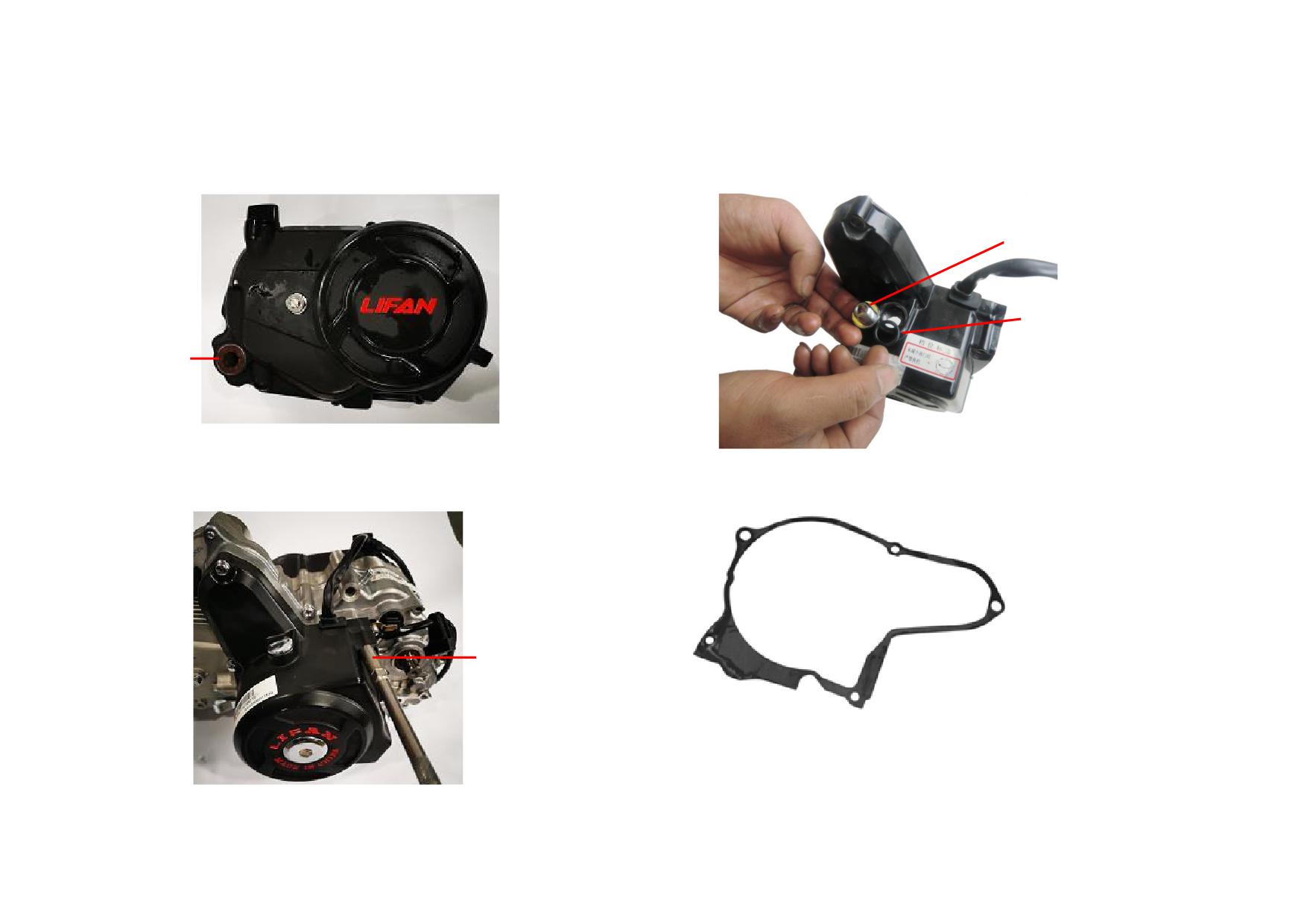
5) Check the oil seal of starting shaft for wear and damage, replace it if
7) Unscrew the view-hole plug, remove the O-ring and check it for wear,
necessary.
replace it if necessary.
VIEW-HOLE PLUG
O-RING
OIL SEAL
6) Unscrew the bolt to remove the left crankcase cover.
8) Remove and check the left crankcase cover gasket, replace it if necessary.
Tightening torque: 8~12N
m
BOLT
2-27
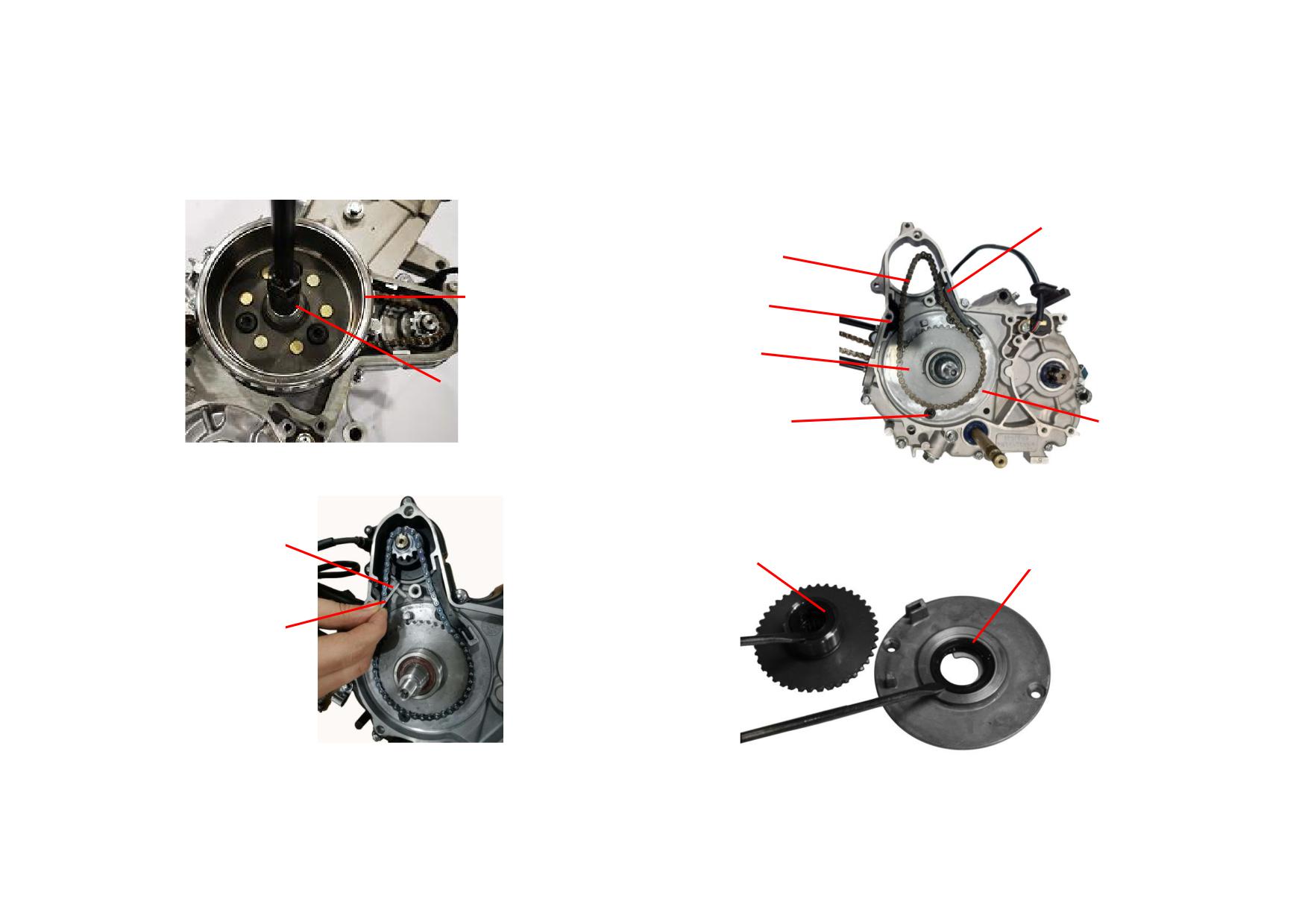
9) Unscrew the nut from the magneto rotor and pull out the rotor.
11) Remove the starting chain, tensioning plate, guide plate and starting clutch
Tightening torque: 40~50N
m
sprocket, unscrew the bolt to remove the plate cover and seal ring.
Tightening torque: 8~12N
m
TENSIONING PLATE
STARTING CHAIN
MAGNETO ROTOR
GUIDE PLATE
STARTING
CLUTCH
SPROCKET
NUT
PLATE
SCREW
COVER
10) Unscrew the bolt to remove the sprocket locating plate.
Tightening torque: 8~12N
m
12) Check the left oil seal of crankshaft and oil seal of starting clutch sprocket
for wear, replace them if necessary.
BOLT
SPROCKET
LEFT OIL SEAL
OIL SEAL
SPROCKET
LOCATING PLATE
2-28
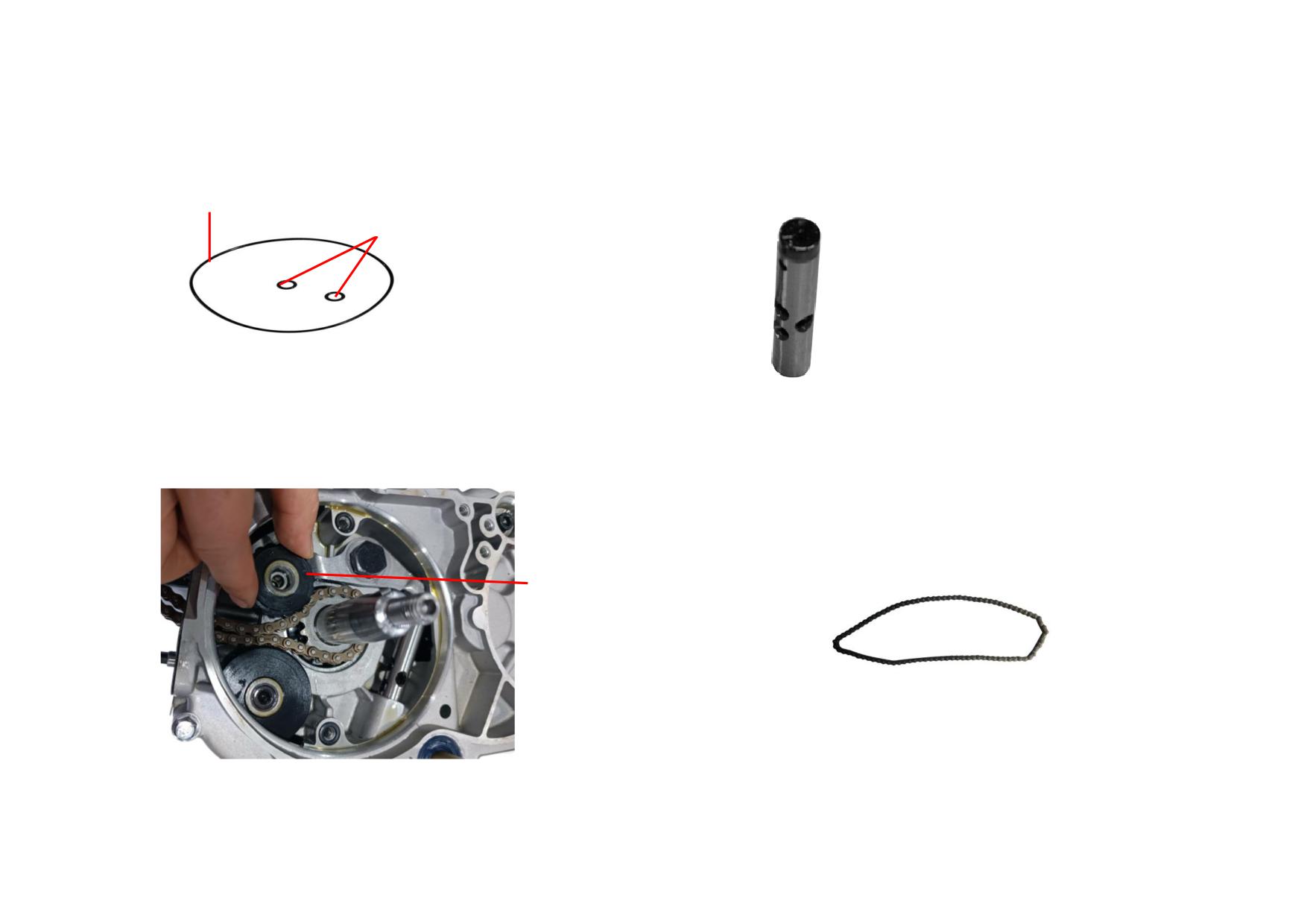
13) Check the plate cover seal ring for damage, replace it if necessary.
15) Remove the tensioning rod, check its head for wear, replace it if OD
exceeds the service limit (Φ11.975mm).
MAGNETO O-RING
MAGNETO O-RING II
14) Remove the tensioning wheel and check it for wear, replace it if necessary.
16) Remove and check the timing chain for stretch and wear, replace it if
necessary.
TENSIONING
WHEEL
2-29
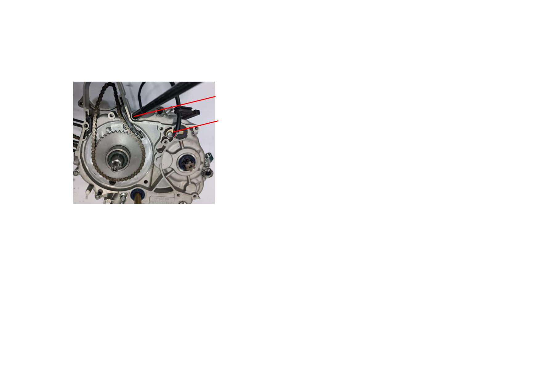
17) Unscrew the crankcase closing bolt and screw of gear indicator compressing
plate. Tightening torque: 8~12N
m
CLOSING BOLT
SCREW OF GEAR
INDICATOR
COMPRESSING
PLATE
2-30
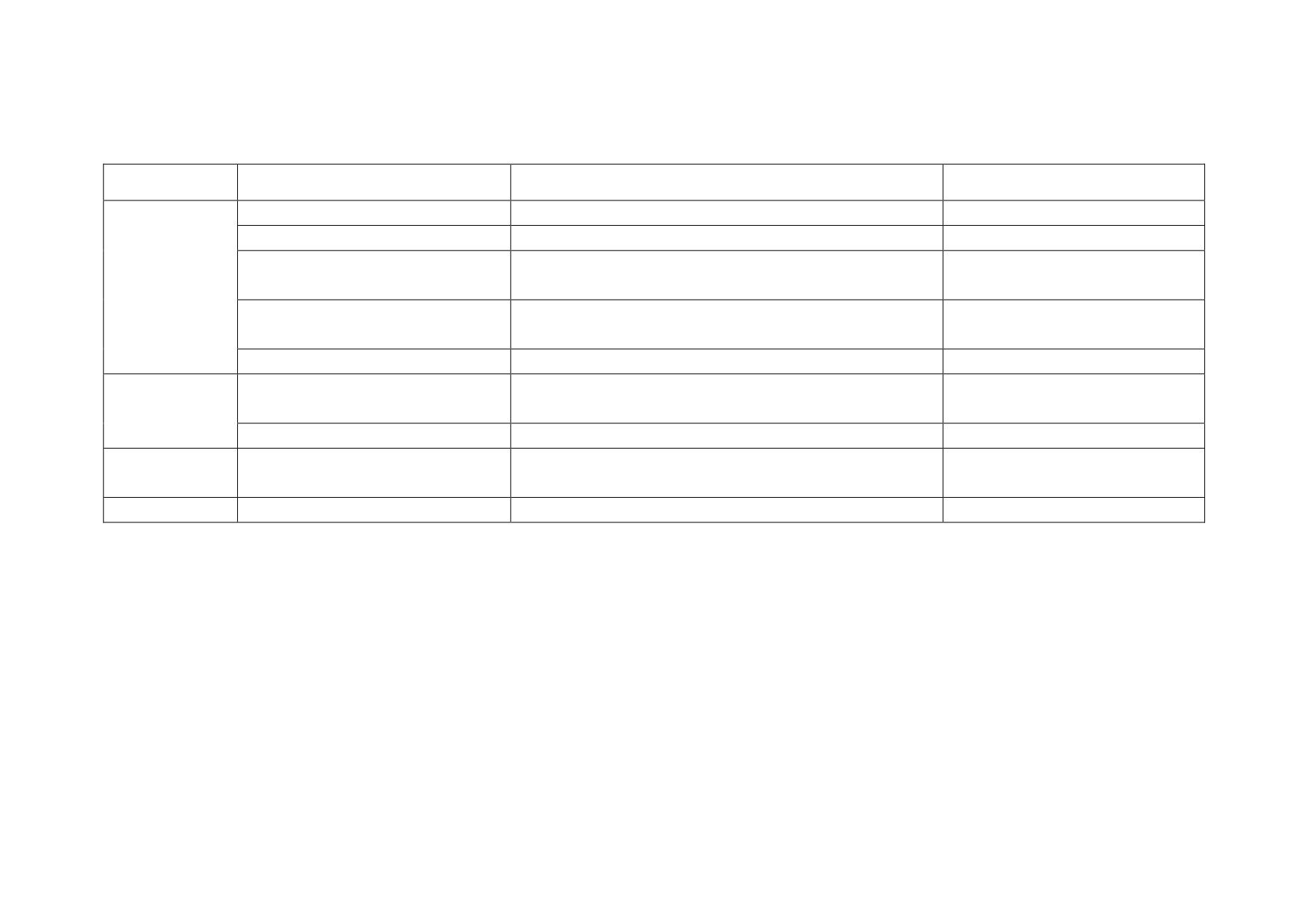
2.4.2 Troubleshooting to Crankcase
Description
Damage Form
Trouble
Service
Cracks on crankcase
Oil leaks from crankcase
Repair or replace
Damaged closing thread
Oil leaks from joint of left crankcase and right crankcase.
Repair or replace
Engine fails or is hard to start. Engine lacks power and has
Repair the thread hole or replace the
Damaged cylinder thread
Crankcase
unstable idle speed.
crankcase
Engine fails or is hard to start. Engine lacks power and has
Broken cylinder bolt
Replace the cylinder bolt
unstable idle speed.
Damaged oil seal
Oil leaks from oil seal.
Replace the oil seal
Right crankcase cover is damaged or
Repair or replace the right crankcase
Right Crankcase
Oil leaks from right crankcase cover.
cracked
cover
Cover
Damaged gasket
Oil leaks between right crankcase cover and crankcase.
Replace the gasket
Left Crankcase
Left crankcase cover is damaged or
Repair or replace the left crankcase
Oil leaks from left crankcase cover.
Cover
cracked
cover
Plate Cover
Broken seal ring
Oil leaks from left crankcase cover.
Replace the seal ring
2-31
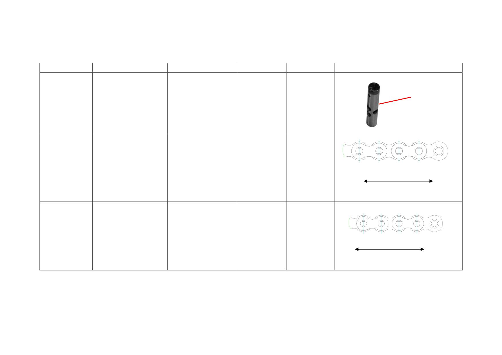
2.4.3 Reference List of Standard Value and Limit Value for Crankcase Maintenance
Description
Test Item
Standard Value
Limit Value
Service
Picture
Tensioning
Replace when
rod OD
Tensioning Rod
Tensioning rod OD
Φ11.985~Φ12
Φ11.975
beyond the limit
value
Length of starting chain
(62 links when
Replace when
387.35~387.92
Starting Chain
determining with 80N
388.92
beyond the limit
(62 links after stretch)
Determine with 80N force
force)
value
Length of timing chain (90
Replace when
links when determining
527.4~527.84
Timing Chain
529
beyond the limit
with 80N force)
(90 links after stretch)
Determine with 80N force
value
2-32
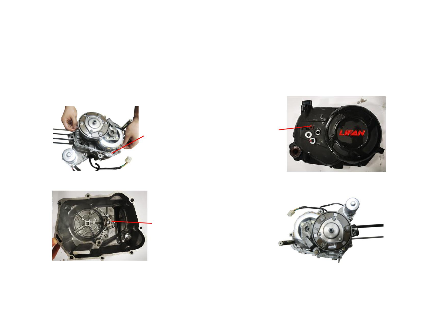
2.5 TRANSMISSION
Clutch
2.5.1 Removal, Maintenance and Installation
1) Remove and check the gasket of right crankcase cover for wear. Replace it if
3) Check the O-ring of clutch adjusting bolt for damage. Replace it if necessary.
necessary.
O-RING
GASKET
2) Check the separating tappet of clutch for wear. Replace it if necessary.
4) Construction of clutch assembly is shown as follows.
SEPARATING TAPPET
2-33
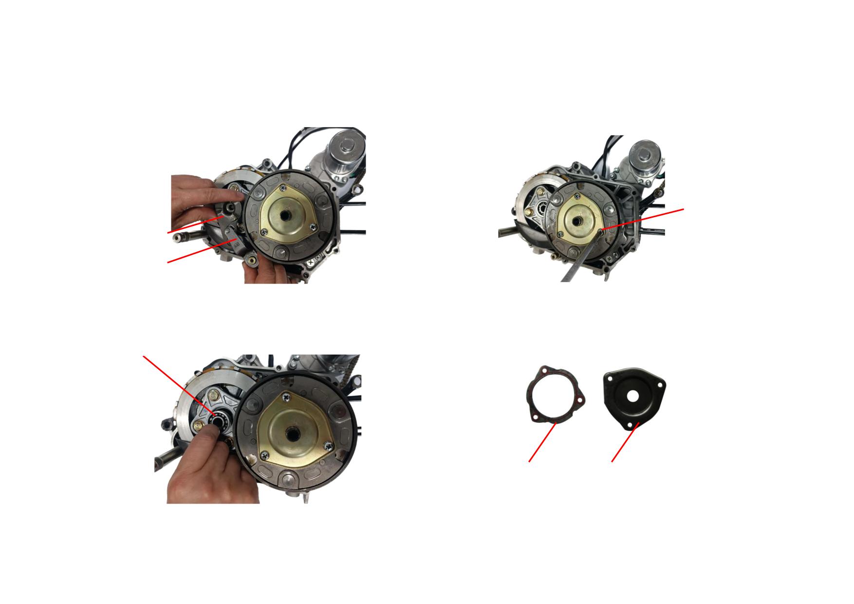
5) Remove and check the clutch operating arm and separating cam plate for
7) Remove the tightening screw (M5) from the auto clutch cover plate.
wear. Replace them if necessary.
(Tightening torque: 6-10N
m)
SCREW (M5)
SEPARATING
CAM PLATE
OPERATING ARM
6) Pull out the clutch bearing, check the bearing for wear and replace it if
8) Check the auto clutch cover plate and its gasket for damage. Replace them if
necessary.
necessary.
CLUTCH BEARING
GASKET
CLUTCH COVER PLATE
2-34
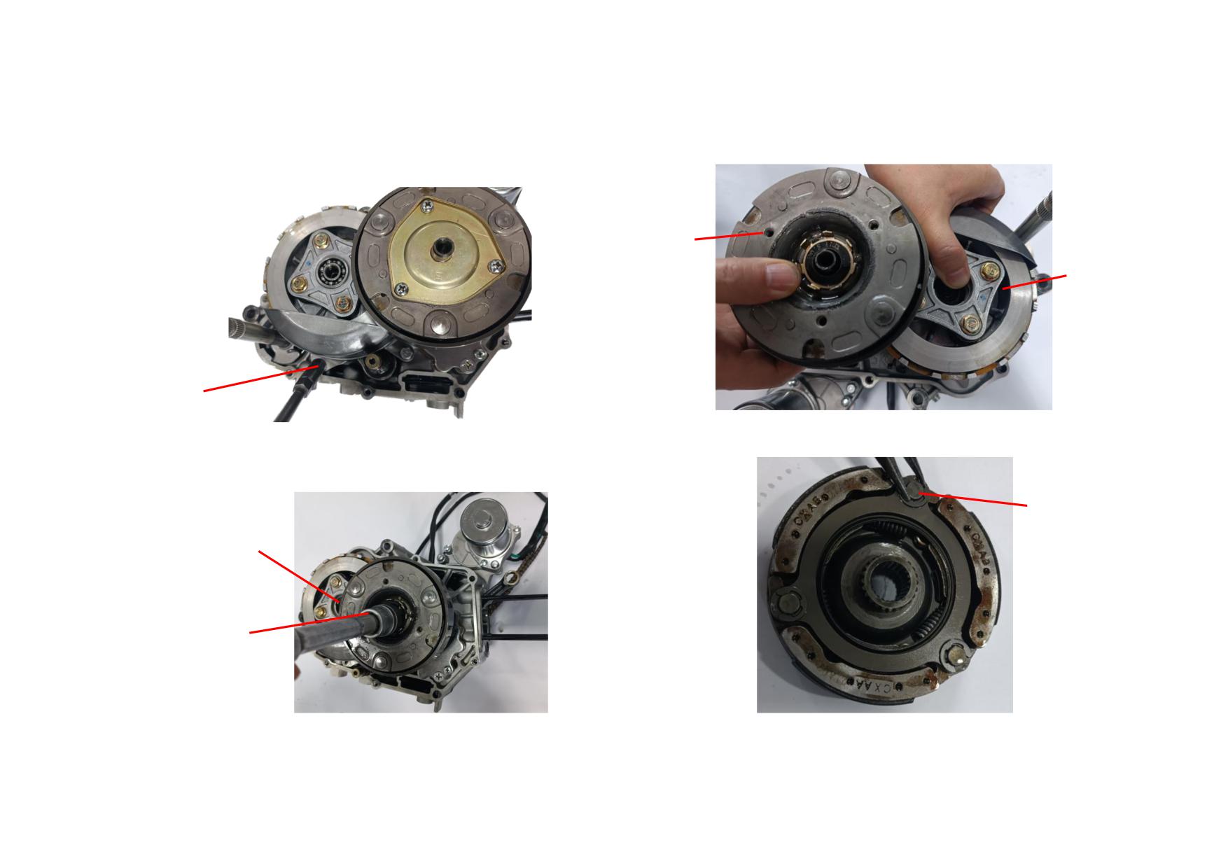
9) Remove the tightening bolt (M6) from the oil box.
11) Remove the snap ring of auto clutch main body.
(Tightening torque: 8-12N
m)
CLUTCH
MAIN BODY
AUTO CLUTCH
MAIN BODY
BOLT
10) Unscrew the locknut from the clutch, check its thread for damage and
12) Remove the snap ring from the auto clutch drive plate assembly.
replace the nut if necessary. (Locknut: M14×1, tightening torque: 45-55N
m)
SNAP RING
LOCKNUT OF
CLUTCH MAIN
BODY
LOCKNUT OF AUTO
CLUTCH MAIN BODY
2-35
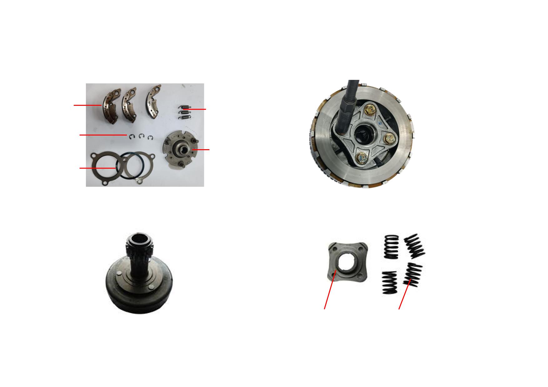
13) Check the snap ring, block, gasket, washer and main body of auto clutch for
15) Unscrew the bolt (M6) from the clutch end cover. (Tightening torque:
damage. Replace the block spring if it is out of elasticity.
8-12N
m)
CLUTCH
DAMPING
SLEEVE
CLUTCH SPRING
SNAP RING
AUTO CLUTCH
COVER PLATE
AUTO CLUTCH
DISC SPRING
14) Check the gear for damage or missing teeth, and replace it if necessary.
16) Check the clutch end cover for damage, and replace it if necessary. And
replace the spring if it is inelastic.
CLUTCH END COVER
SPRING
2-36
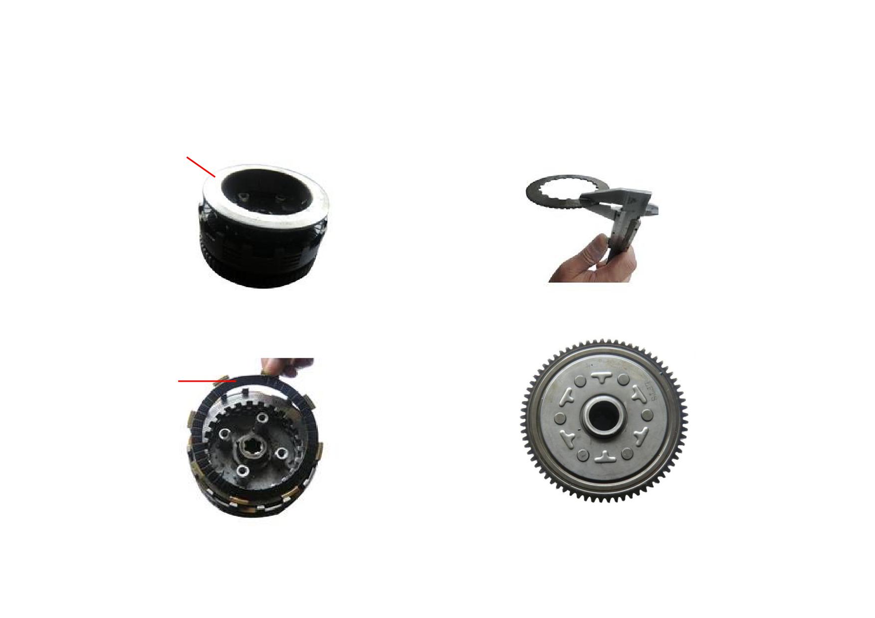
17) Remove and check the clutch pressing disc for damage, replace it if
19) Remove the clutch drive plate and driven plate (friction plate), and measure
necessary.
their thicknesses with a caliper. Replace the plates if they exceed the service
limits (2.8mm & 1.4mm).
CLUTCH PRESSING DISC
18) Remove and check the clutch pressing plate for wear. Measure the
20) Check the primary driven gear for wear, and replace it if necessary.
deformation flatness with a feeler gauge, and replace the pressing plate if it
exceeds the service limit 0.2mm.
CLUTCH PRESSING
PLATE
2-37
2.5.2 Troubleshooting to Clutch
Description
Cause
Fault
Remedy
The drive disc grooves are worn into
Clutch is slipping, not disengaged thoroughly
Trim the grooves with a saw or replace
Clutch drive disc
serrated shape.
with a loud noise.
the drive disc.
Clutch drive plate &
The contact face is excessively worn.
Clutch is slipping.
Replace
pressing plate
Excessively worn
Clutch is slipping, not disengaged thoroughly.
(thickness<2.8/1.4mm)
Clutch drive/driven plate
Replace the drive/driven plate as a set.
Severely deformed
Clutch is slipping.
Clutch spring
Inelastic or broken
Do.
Replace the spring.
2-38
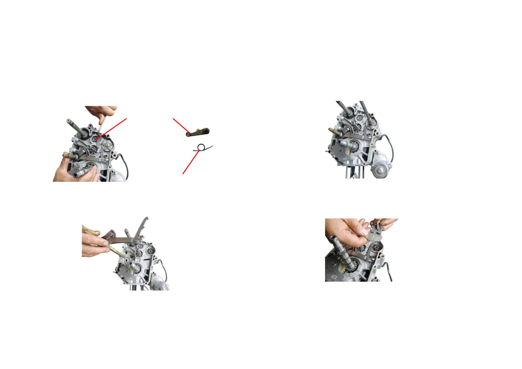
Gearshift Mechanism
2.5.3 Removal, Maintenance and Maintenance
1) Unscrew the bolt (M6) to remove the gear locating plate, check the locating
3) Unscrew the bolt (M6) of gear indicator from the gearshift cam assembly,
plate for damage, and replace it if necessary. Replace the spring if it is inelastic.
and remove the gear indicator contact. (Tightening torque: 8-12N
m)
(Tightening torque: 8-12N
m)
GEAR LOCATING PLATE
SPRING
2) Remove and check the gearshift shaft for wear, and replace it if necessary.
4) Check the gear indicator contact for wear, and replace it if necessary.
2-39
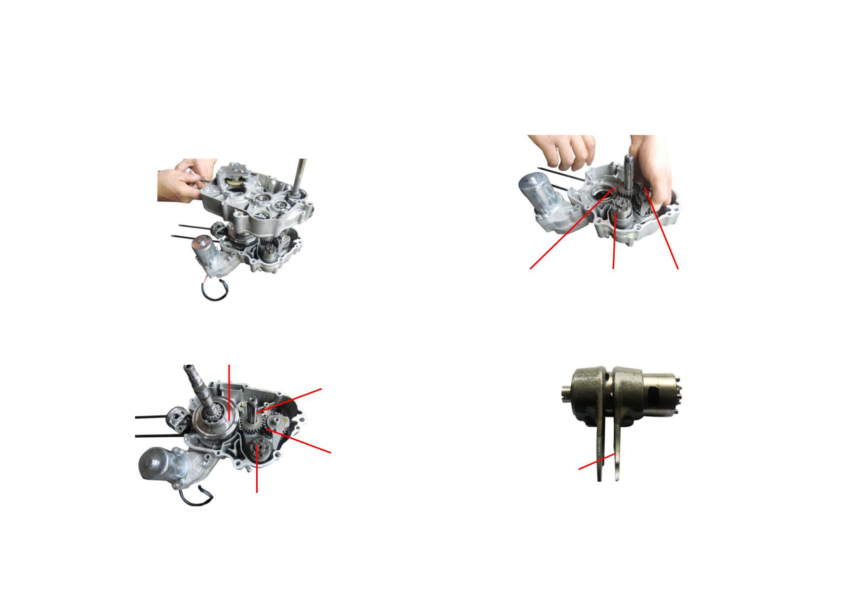
5) Unscrew the tightening bolt (M6) from the crankcase to remove the right
7) Remove the gearshift cam assembly, main shaft and countershaft comp.
crankcase assembly. Check the crankcase gasket for damage, replace it if
necessary. (Tightening torque: 8-12N
m)
MAIN SHAFT
GEARSHIFT CAM
COUNTERSHAFT
8) Remove the fork from the gearshift cam, check it for wear, and replace it if
6) Remove the crank connecting rod comp.
its claw thickness exceeds the service limit (3.8mm).
CRANK CONNECTING ROD
MAIN SHAFT
COUNTERSHAFT
FORK
GEARSHIFT CAM
2-40
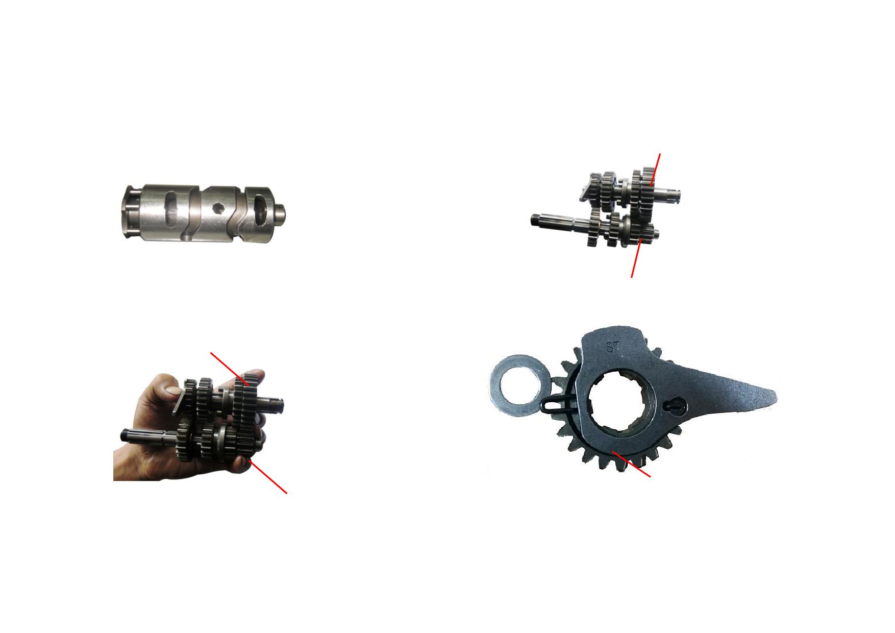
9) Check the drum and fork groove of gearshift cam for wear, replace the drum
11) Check the gears of main shaft and countershaft for wear, and replace them if
if it exceeds the service limit (Φ33.93mm).
deep pits or missing teeth occur.
COUNTERSHAFT
MAIN SHAFT
10) Check the main shaft and countershaft, and replace them if their matching
12) Remove and check the 4th gear of countershaft for wear.
gap is excessively large.
COUNTERSHAFT
COUNTERSHAFT 4TH GEAR
MAIN SHAFT
2-41
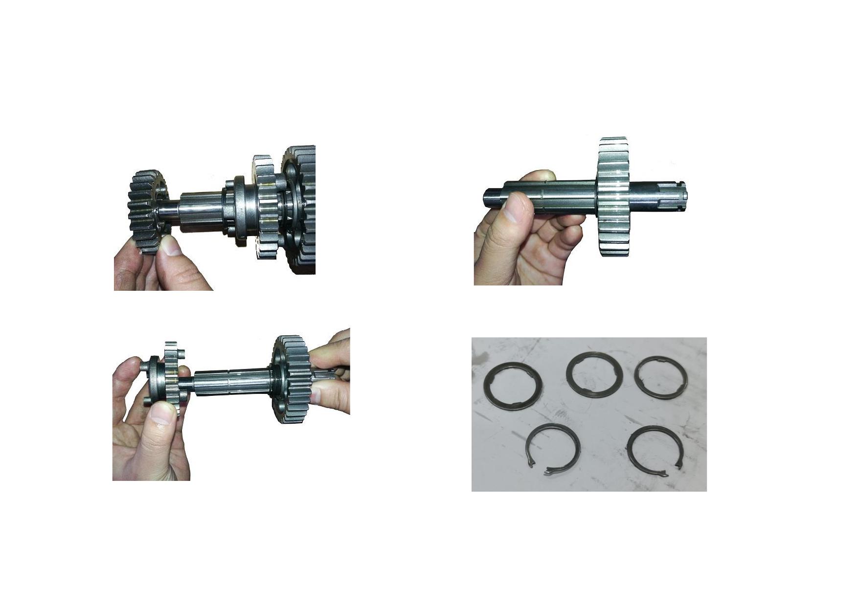
13) Remove and check the countershaft 3rd gear and its washer for wear.
15) Check the countershaft 1st gear for wear, and replace the gear if the bore
Replace them if the bore exceeds the service limit (Φ20.073mm).
exceeds the service limit (Φ23.073mm).
14) Check the countershaft 2nd gear for wear, and replace it if necessary.
16) Check all countershaft washers and snap rings for wear, and replace them if
necessary.
2-42
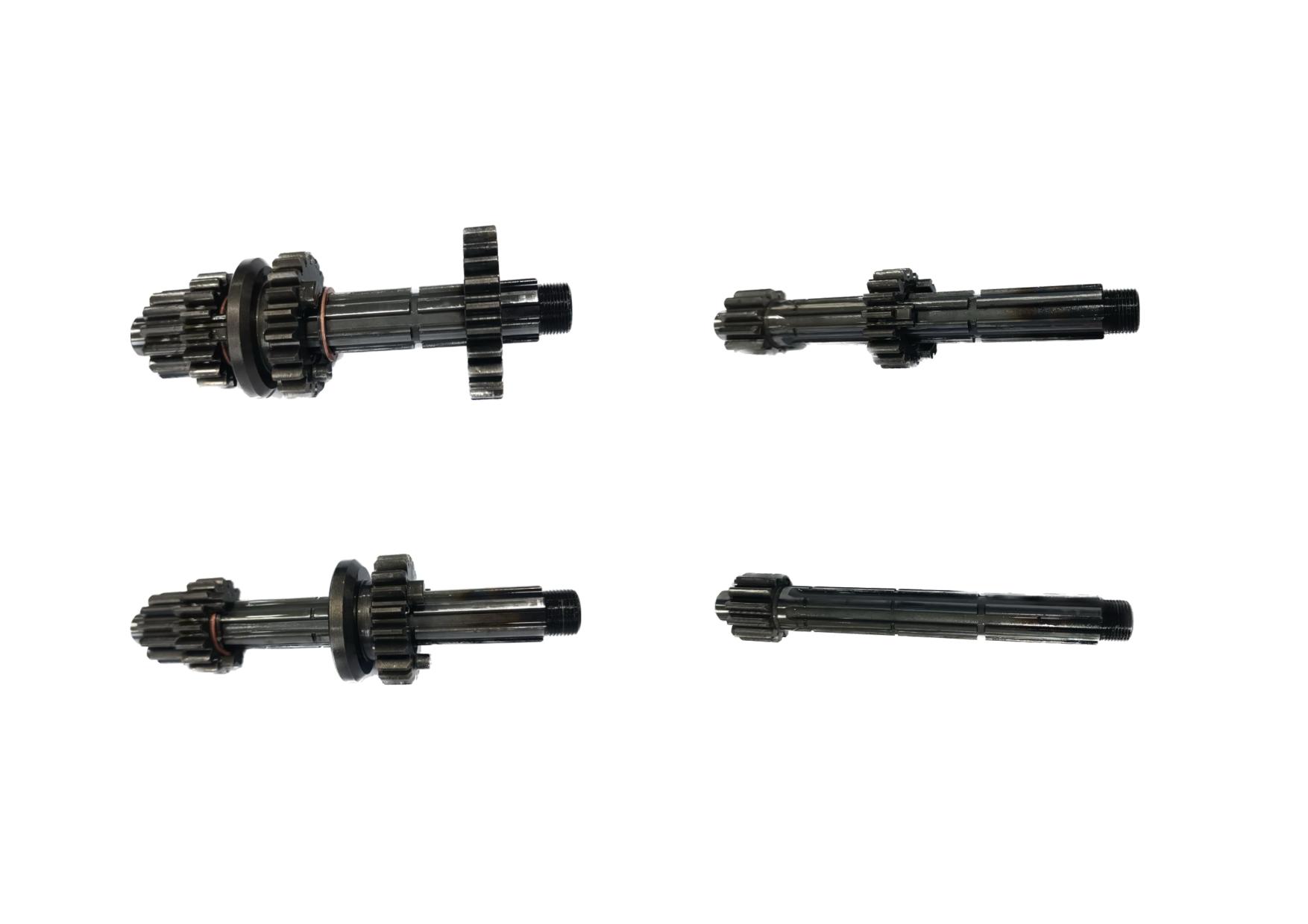
17) Remove and check the main shaft 4th gear and spline washer for wear, and
19) Remove and check the main shaft 2nd gear for wear, and replace it if the
replace them if the bore exceeds the service limit (Φ17.075mm).
bore exceeds the service limit (Φ17.075mm).
18) Remove and check the main shaft 3rd gear for wear, and replace it if
20) Check the main shaft and 1st gear for wear, and replace them if necessary.
necessary.
2-43
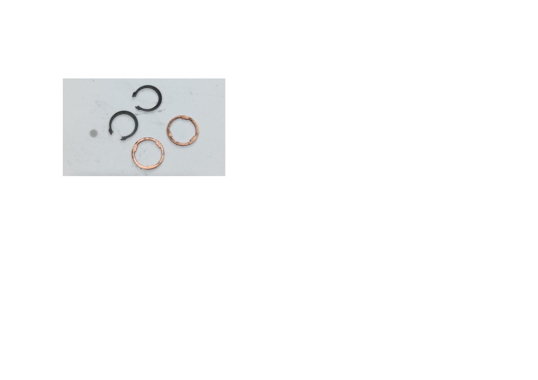
21) Check the inner spline washers and snap rings on the main shaft for
deformation, and replace them if necessary.
2-44
2.5.4 Troubleshooting to Gearshift Mechanism
Description
Cause
Fault
Remedy
The teeth surfaces have pits, teeth are broken
Abnormal noise occurs when the gearbox is
Replace the gear.
or gear inner hole is severely worn.
working. It's difficult to gearshift.
The meshing face of gear end is worn into an
It's easy to disengage.
Do.
Gear
arc shape.
Gear meshing hole is worn into trumpet shape.
Do.
Do.
Fork groove is excessively worn.
Do.
Do.
Fork claw is excessively worn.
Do.
Replace the fork.
Fork
Fork is deformed.
It's difficult to gearshift.
Do.
Fork hole is excessively worn.
Do.
Do.
Gearshift cam
Gearshift groove is excessively worn.
Do.
Replace the gearshift cam.
Excessive wear or damage
Do.
Replace the gear locating plate.
Gear locating
plate
Spring is inelastic or broken.
It's easy to disengage.
Replace the torsion spring of locating plate.
Spline is damaged.
It fails to gearshift.
Replace the gearshift shaft.
Gearshift shaft is deformed.
It's difficult to gearshift.
Do.
Gearshift shaft
Gearshift shaft is worn or broken.
Do.
Do.
Return spring is inelastic or broken.
It's difficult to gearshift, or pedal fails to return.
Replace the return spring.
Oil seal
Oil seal is severely worn, damaged or aged.
Oil leaks.
Replace the oil seal.
2-45
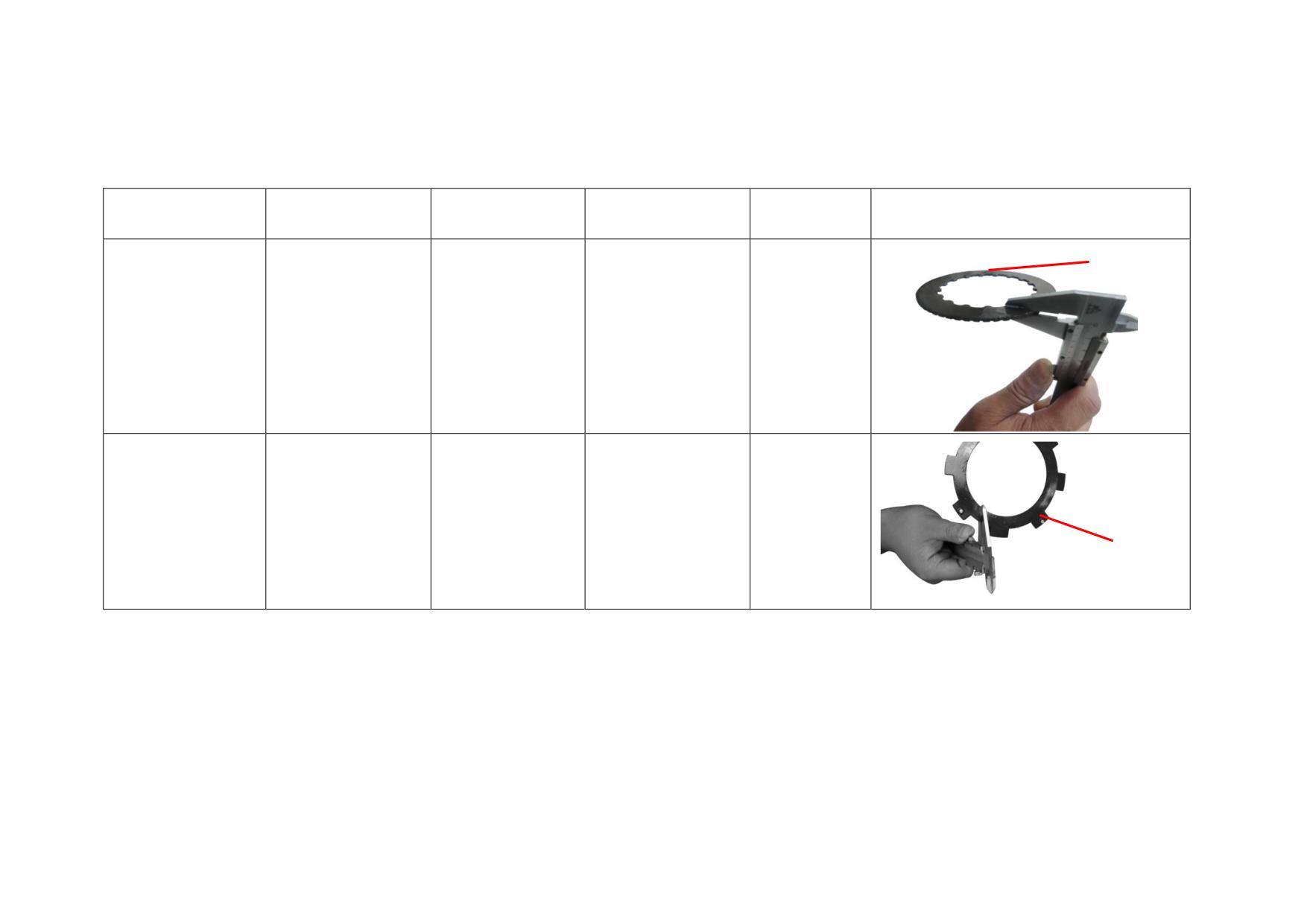
2.5.5 Reference List of Standard Value and Service Limit Value for Transmission Mechanism
Description
Test Item
Standard Value
Limit Value
Service
Picture
THICKNESS
Replace if it
Auto clutch driven
Thickness
2.6-2.9
2.35
exceeds the
plate
limit value.
Replace if it
Auto clutch drive
Thickness
1.6-1.75
1.35
exceeds the
plate I
limit value.
THICKNESS
2-46
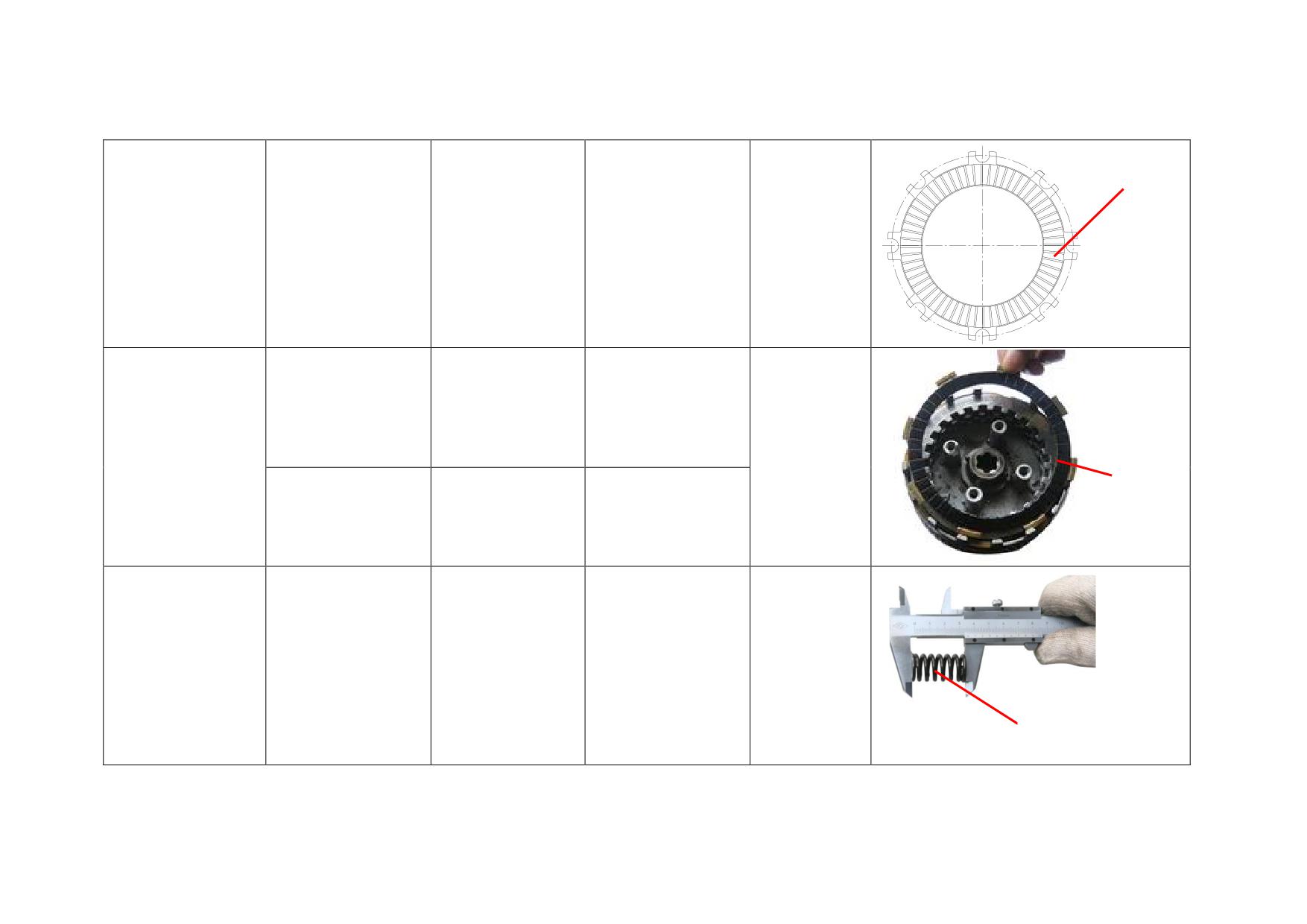
THICKNESS
Replace if it
Auto clutch drive
Thickness
3.35-3.65
3.1
exceeds the
plate II
limit value.
Thickness
1.45-1.55
1.2
Replace if it
Auto clutch pressing
exceeds the
AUTO
plate
CLUTCH
limit value.
PRESSING
PLATE
Flatness
0-0.1
0.2
Replace if it
Auto clutch spring
Free height
17.7-18.3
14..2
exceeds the
limit value.
FREE HEIGHT
2-47
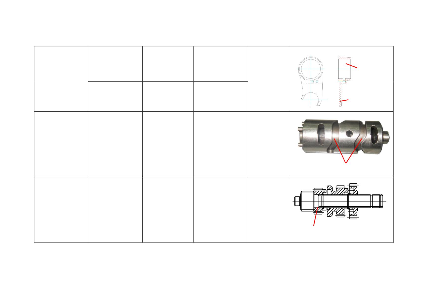
Inner hole diameter
Φ34-Φ34.039
Φ34.06
INNER HOLE
Replace if it
DIAMETER
Fork
exceeds the
limit value.
Fork thickness
4.85-4.95
4.8
FORK THICKNESS
Replace if it
Gearshift cam
Groove width
6.05-6.15
6.18
exceeds the
limit value.
GROOVE WIDTH
Replace if it
Main shaft 2nd gear
Inner hole diameter
Φ17.016-Φ17.043
Φ17.075
exceeds the
limit value.
MAIN SHAFT 2ND GEAR
2-48
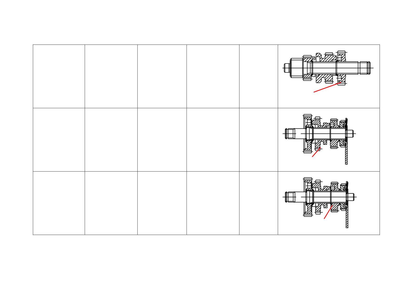
Replace if it
Main shaft 4th gear
Inner hole diameter
Φ17.016-Φ17.043
Φ17.075
exceeds the
limit value.
MAIN SHAFT 4TH GEAR
Replace if it
Countershaft 1st gear
Inner hole diameter
Φ23.02-Φ23.041
Φ23.073
exceeds the
limit value.
GEAR
COUNTERSHAFT 1ST
Replace if it
Countershaft 3rd gear
Inner hole diameter
Φ20.02-Φ20.041
Φ20.073
exceeds the
limit value.
COUNTERSHAFT 3RD GEAR
2-49
2.6 CRANK MECHANISM
2.6.1 Removal, Maintenance and Installation
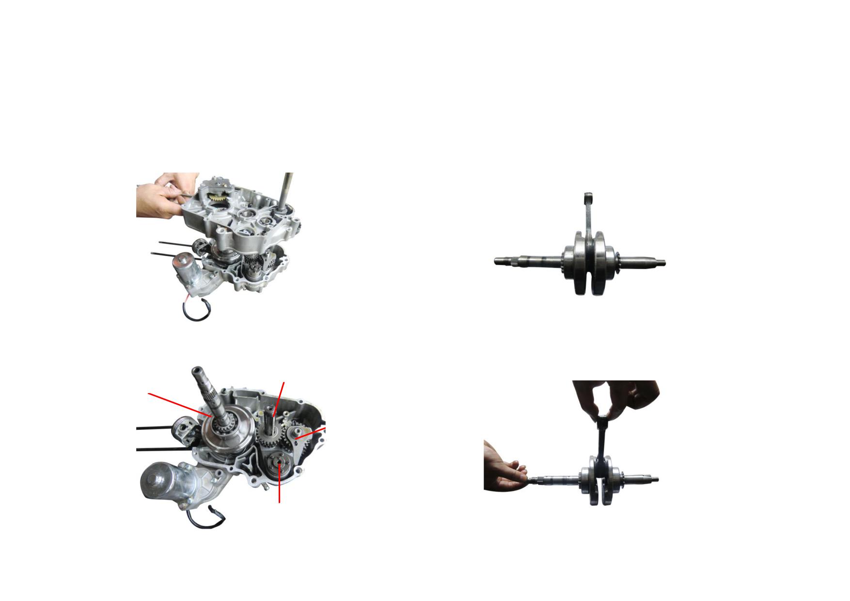
1) Check the main shaft bearing, countershaft bearing and crankshaft bearing.
3) Remove the crank connecting rod and the construction is shown as the
Replace them if they're severely worn.
following figure.
2) The construction of crank connecting rod, main shaft comp., countershaft
4) Measure the gap of connecting rod big end with thickness gauge and
comp. and gearshift cam are shown as the following figure.
micrometer gauge. Replace it with a new one , if it exceeds the service limit
(axial: 0.48 mm, radial: 0.05 mm).
MAIN SHAFT COMP.
CRANK CONNECTIND ROD
COUNTERSHAFT COMP.
GEARSHIFT CAM
2-50
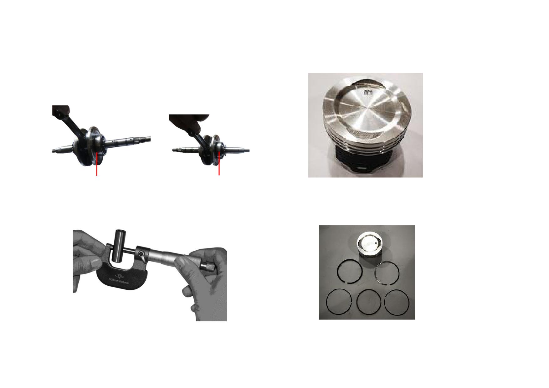
5) Check the timing drive sprocket of connecting rod and replace it if necessary.
7) Clear away the carbon deposit on the piston top.
Make sure the tooth valleys between any two teeth are aligned with the center
line of crankshaft key slot. And check the left and right bearings of crankshaft
for wear. Replace them if necessary.
LEFT BEARING
RIGHT BEARING
8) Remove the piston rings from the piston. Parallel push each piston ring into
6) Measure the O.D. of the piston pin with a micrometer. Replace it with a new
the cylinder block and check them for wear and elasticity. Measure the opening
one, if it exceeds the service limit (Φ12.78mm).
clearance of each ring with thickness gauge and replace all the piston rings as a
set if they exceed the service limit (Piston ring I&II: 0.7mm, Oil ring: 1.9mm).
2-51
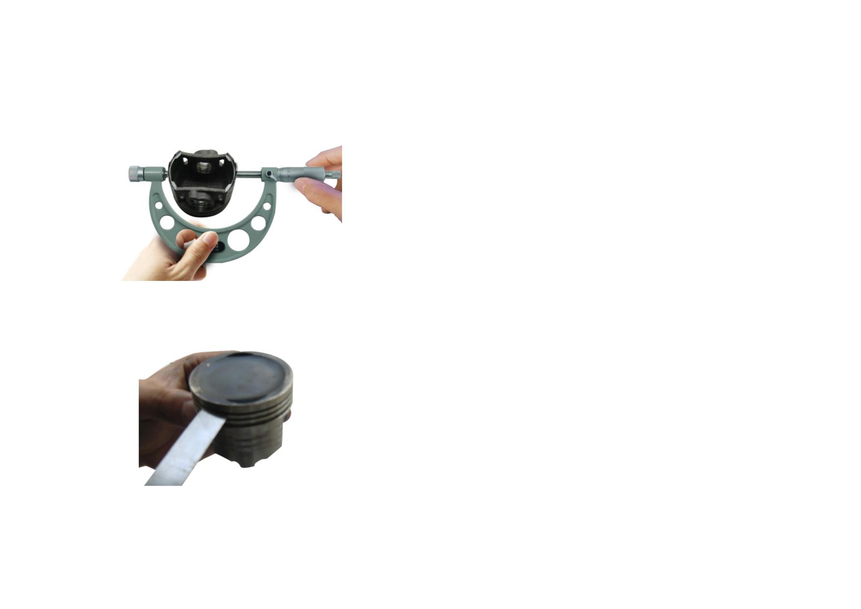
9) Measure the O.D. at the piston skirt 10mm from the piston bottom. Replace
the piston if it exceeds the service limit (Φ53.15mm).
10) Measure the width of piston ring groove. Replace the piston, if it exceeds
the service limit (Piston ring I&II: 0.89mm, Oil ring: 2.09mm).
2-52
2.6.2 Troubleshooting to Crank Mechanism
Description
Cause
Fault
Remedy
Carbon deposit on the piston top
Engine overheats.
Clear away carbon deposit.
Engine fails or is hard to start. Engine lacks power
Carbon deposit in the piston ring
with thick blue smoke exhausting from the
Do.
groove
exhaust pipe.
Piston
Scratches on the surface of piston skirt
Do.
Replace the piston.
Piston is excessively worn.
Do.
Do.
Piston ring groove is excessively worn .
Thick blue smoke exhausts from the exhaust pipe.
Do.
Piston pin hole is excessively worn.
Knocking sound from piston pin and cylinder
Do.
Crankshaft Pin
Excessively worn
Knocking sound from big-end bearing
Replace the crank connecting rod.
Needle bearing is excessively worn.
Do.
Do.
Bearing
Crankshaft bearing is excessively worn
Abnormal noise from crankshaft
Replace the crankshaft bearing.
or damaged.
Engine fails or is hard to start. Engine lacks power
Piston ring is broken
with thick blue smoke exhausting from the
Replace the piston rings as a set.
exhaust pipe.
Piston Ring
Piston ring is excessively worn.
Do.
Do.
Engine lacks power with thick blue smoke
Piston ring is inelastic.
Do.
exhausting from the exhaust pipe.
Improper installation
Do.
Reassemble the piston rings.
Piston Pin
Excessively worn
Knocking sound from piston pin
Replace the piston pin.
Small-end hole is excessively worn.
Do.
Replace the connecting rod.
Connecting Rod
Connecting rod is bent.
Knocking sound from cylinder
Do.
Big-end hole is excessively worn.
Knocking sound from big-end bearing
Do.
Sprocket is excessively worn or
Incorrect timing/abnormal noise/engine lacks
Timing Drive Sprocket
Replace the timing drive sprocket.
damaged.
power.
2-53
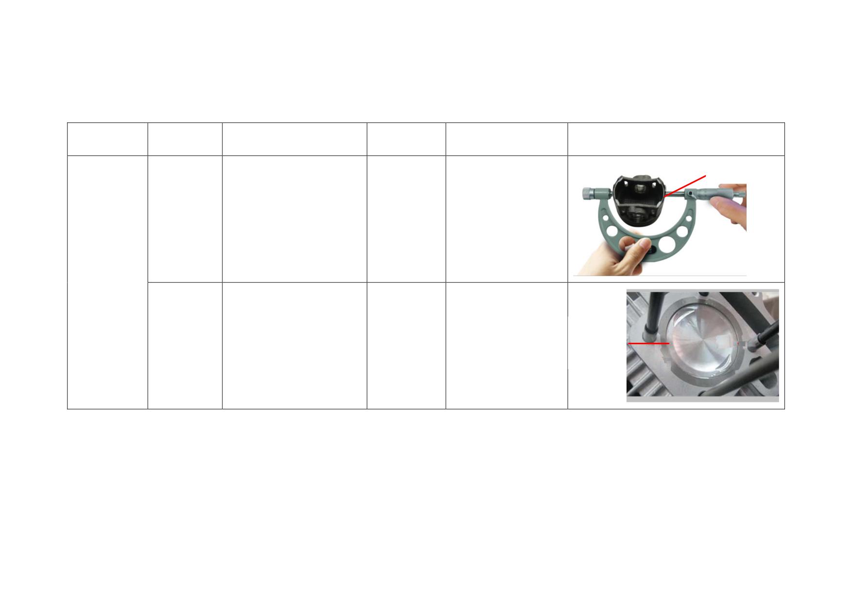
2.6.3 Reference List of Standard Value and Service Limit value for Crank Mechanism
Description
Test Item
Standard Value
Limit Value
Service
Picture
PISTON SKIRT
DIAMETER
Diameter of
Replace if it exceeds the
Φ53.475-Φ53.485
Φ53.440
piston skirt
service limit.
Piston
CYLINDER
Cylinder
Replace if it exceeds the
MATCHING
0.020-0.030
0.08
matching gap
service limit.
GAP
2-54
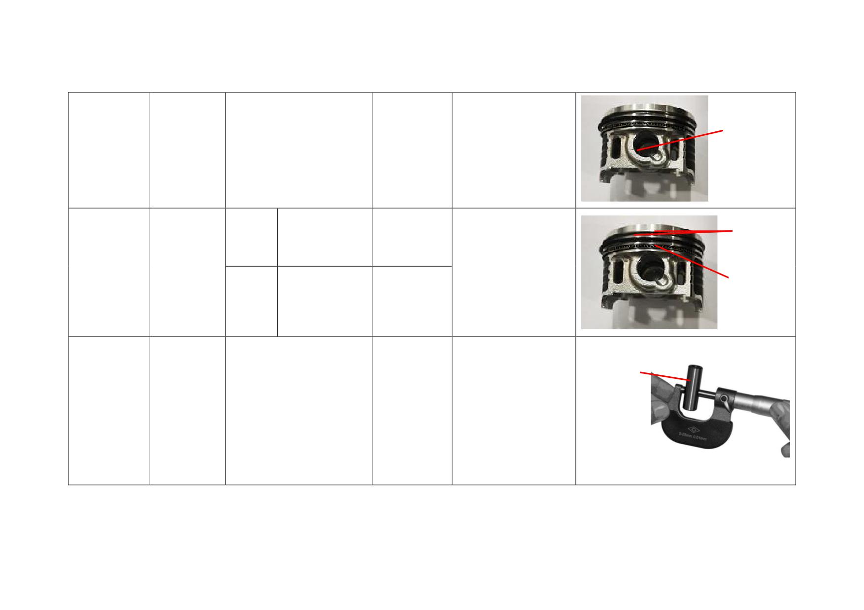
PIN HOLE I.D.
I.D. of pin
Replace if it exceeds the
Φ13.002-Φ13.008
Φ13.05
hole
service limit.
Piston
PISTON
ring I&
0.02-0.055
0.09
RING I & II
Gap between
II
piston ring
Replace if it exceeds the
Piston
OIL RING
and piston
service limit.
ring slot
Oil ring
0.035-0.150
0.2
PISTON PIN
DIAMETER
Replace if it exceeds the
Piston pin
Diameter
Φ12.992-Φ12.998
Φ12.978
service limit.
2-55
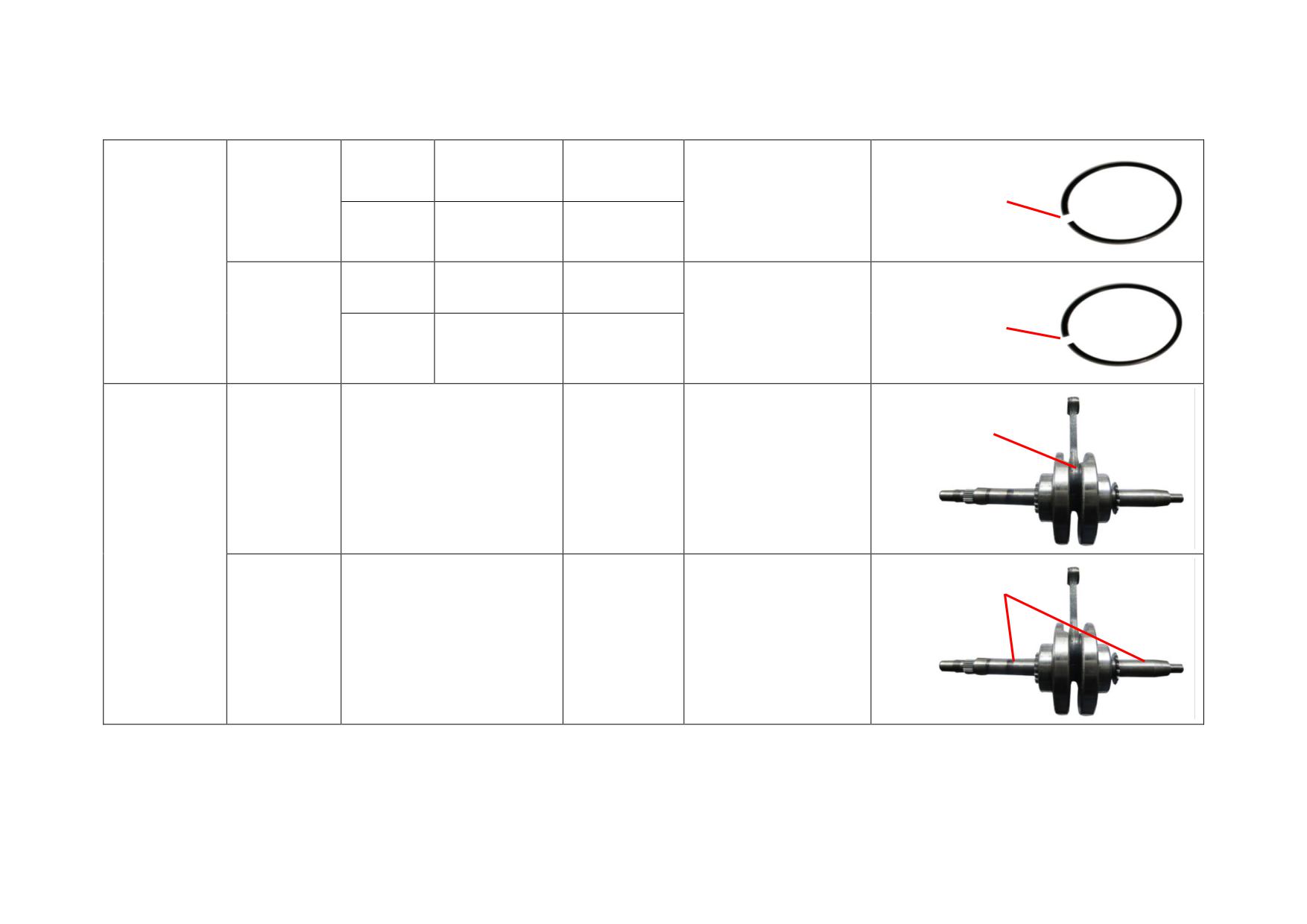
Piston ring
0.10-0.25
0.5
OPEN GAP (WHEN
I
Replace if it exceeds the
Close gap
ASSEMBLED)
service limit.
Piston ring
0.25-0.35
0.5
II
Piston ring set
Piston ring
Approx. 6.2
7.2
I
Replace if it exceeds the
Open gap
OPEN GAP (NOT
Piston ring
service limit.
Approx.6.6
7.5
ASSEMBLED)
II
BIG-END BACKLASH
Backlash of
Replace if it exceeds the
connecting rod
0.09-0.36
0.48
service limit.
big-end
Crank
connecting rod
LEFT & RIGHT CRANKSHAFT
RUNOUT
Runout of left
Replace if it exceeds the
and right
0-0.03
0.05
service limit.
crankshaft
2-56
2.7 STARTERS
Kick-starter
2.7.1 Removal, Maintenance and Installation
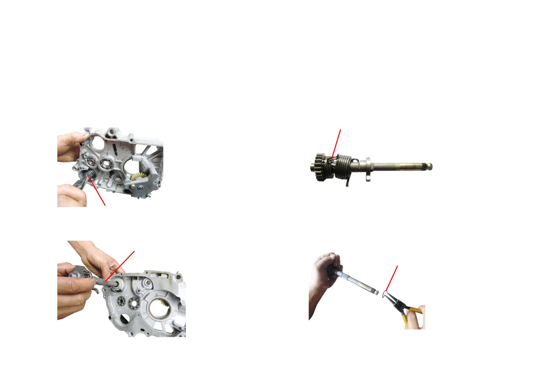
1) Remove and check the starting shaft spring and spring seat. Replace them if
3) Remove the starting shaft assy.
they are worn or deformed.
STARTING RETURN SPRING
STARTING SHAFT SPRING
2) Check the starting return spring for elasticity. Replace it if it's inelastic.
4) Remove the starting shaft circlip and ratchet spring seat. Replace them if they
are severely worn.
STARTING SHAFT ASSY.
STARTING SHAFT CIRCLIP
2-57
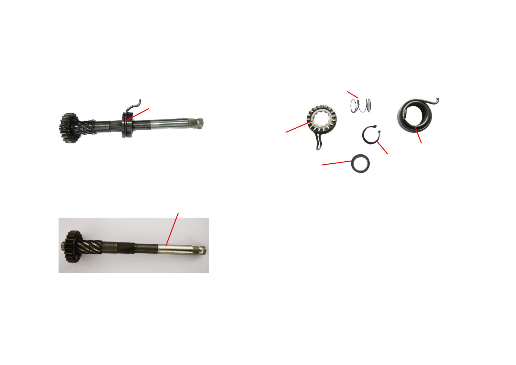
5) Remove the starting shaft spring and ratchet. Replace them if they are
7) Remove and check the starting shaft circlip, starting ratchet, starting return
severely deformed or worn.
spring and washer. Replace them if they're deformed or worn.
STARTING SHAFT SPRING
RATCHET
RATCHET
STARTING RETURN SPRING
CIRCLIP
WASHER
6) Check the starting shaft spline and replace it if it's severely deformed or
worn.
STARTING SHAFT
2-58
2.7.2 Troubleshooting to Kick-starter
Description
Cause
Fault
Remedy
The spline slips with the starting lever
Starting lever
Slips in starting
Replace the starting lever.
connected.
Gear is worn.
Do.
Starting gear
Replace the gear.
Gear is worn or damaged.
Difficult to start
Ratchet is severely worn.
Slips in starting
Replace the ratchet.
Ratchet
Friction spring of starting gear is broken.
Do.
Replace the spring.
The spline connected with starting lever is
Do.
Replace the starting shaft.
Starting shaft
damaged.
Return spring is broken.
Starting lever fails to return.
Replace the spring .
2-59
Electric starter
2.7.3 Removal, Maintenance and Installation
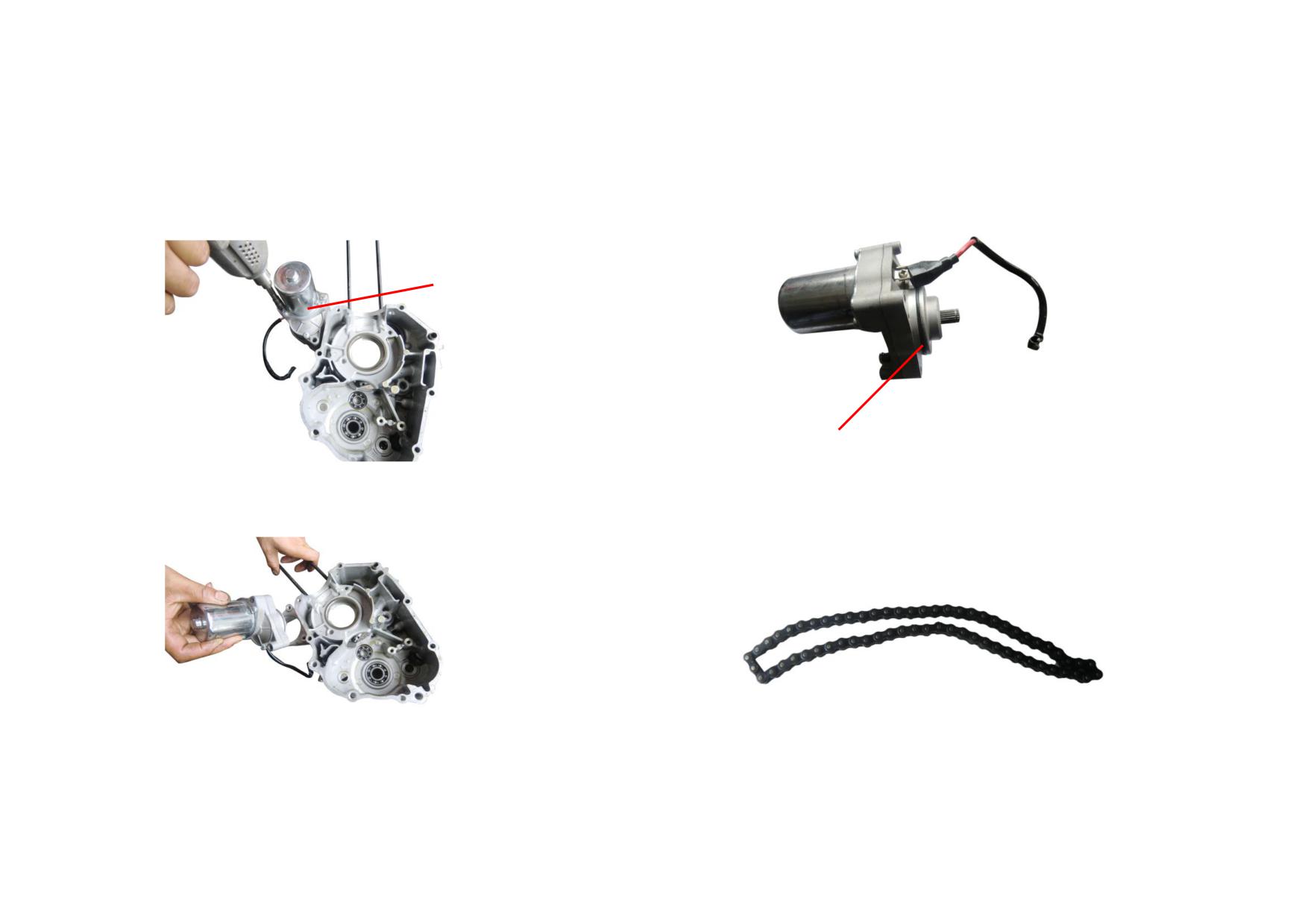
1) Unscrew tightening bolt (M6) of starting motor. (Tightening torque 8-12N
m)
3) Check the O-ring on starting motor and replace it if it's broken.
STARTING MOTOR ASSY.
O-RING
2) Knock the starting motor assy. with a plastic hammer and remove it.
4) Check the starting chain for stretch and wear. Replace it if it's stretched for
too long or severely worn.
2-60
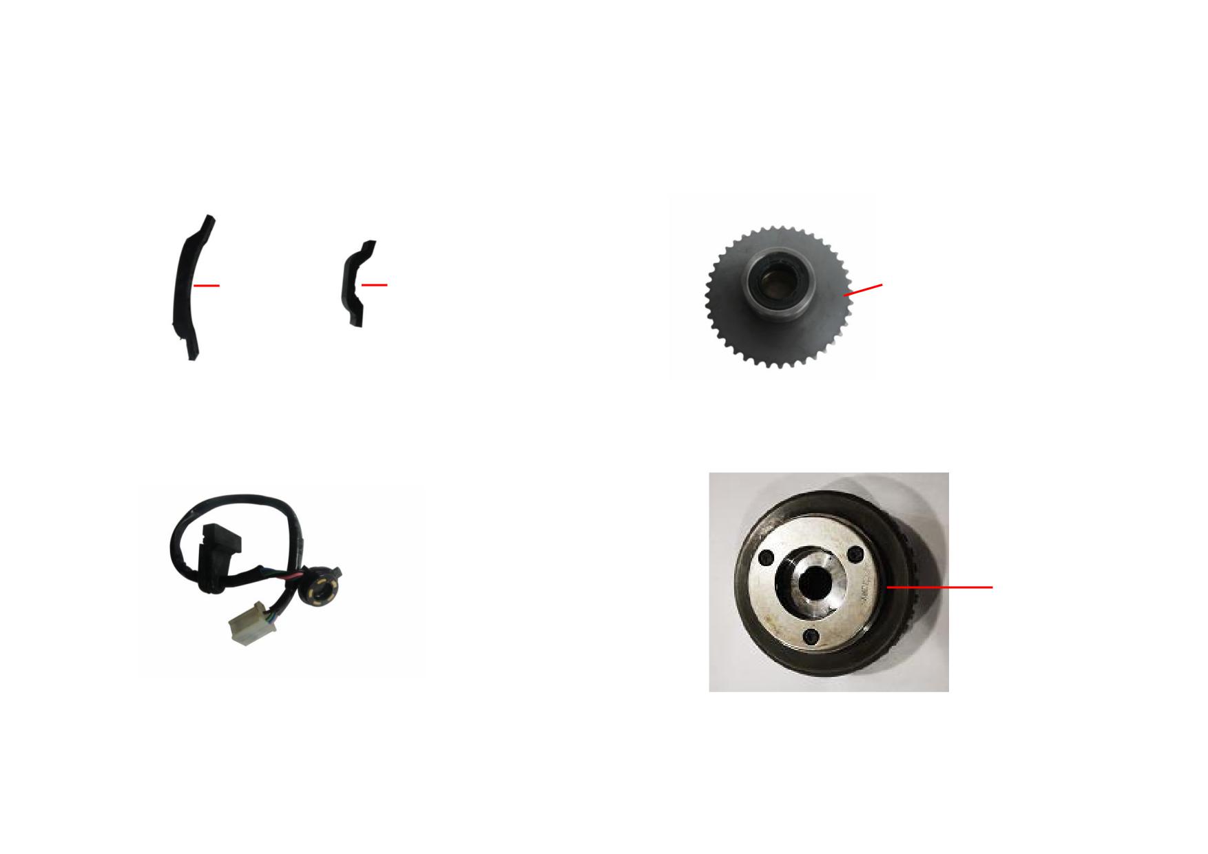
5) Check the tension plate and the guide plate for wear. Replace them if they are
7) Check the starting clutch sprocket weldment for wear. Replace it if it's
severely worn.
severely worn.
GUIDE PLA
TE
TENSION PLATE
STARTING CLUTCH SPROCKET COMP.
8) Check the body, roller and spring of the starting clutch for wear. Replace
6) Check the gearshift indicator. Repair or replace it if necessary.
them if they're severely worn. The roller is required to be able to return freely
and not to be stuck.
STARTING CLUTCH
2-61
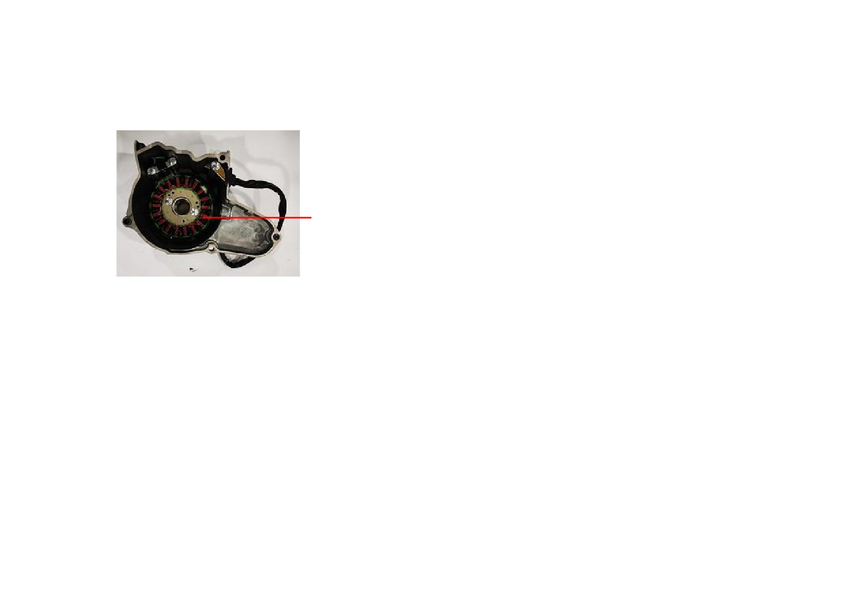
9) Remove the bolt (M6) of magneto stator coil from the left crankcase cover
(Tightening torque: 8-12N·m). Check and replace it if it's damaged.
MAGNETO STATOR COMP.
2-62
2.7.4 Troubleshooting to Electric Starter
Description
Cause
Fault
Service
Carbon brush is excessively worn.
Starting motor lacks power or fails to work.
Replace the starting motor.
The carbon brush spring is broken or
Starting motor lacks power.
Do.
inelastic.
The rotor commutator surface is fouled.
Do.
Do.
Starting motor
The rotor commutator surface is burnt or
Do.
Do.
damaged.
The rotor commutator surface is excessively
Starting motor lacks power or fails to work.
Do.
worn.
Rotor coil is damaged by short circuit or
Starting motor fails to work.
Do.
broken circuit.
The contact face of starting clutch and roller
Starting clutch slips or has abnormal noise.
Replace the starting clutch gear.
is damaged or excessively worn.
Starting clutch
The contact face of starting clutch and roller
Do.
Replace the starting clutch.
is damaged or worn into groove.
The roller is excessively worn or damaged.
Do.
Do.
2-63
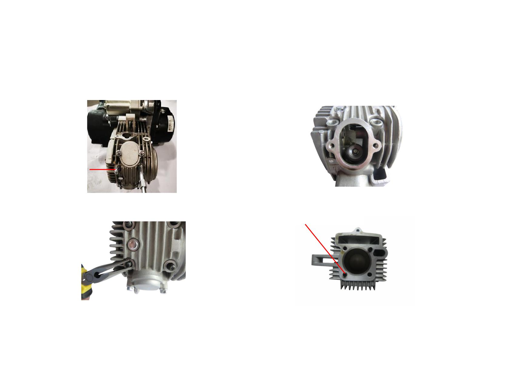
2.8 LUBRICATION SYSTEM
2.8.1 Removal, Maintenance and Installation
1) Remove the cap nut from the engine. (Tightening torque 10-14N
m)
3) Check the oil passage in cylinder head for block.
CAP NUT
2) Step the starting lever and start the engine and check the copper washer for
4) Check the oil passage in cylinder block for block.
oil leaks. Clean the oil passage if necessary.
CYLINDER BLOCK OIL PASSAGE
2-64
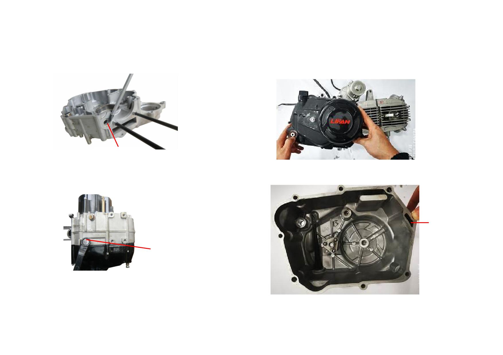
5) Check the crankcase oil passage and clean it.
7) Unscrew the bolt (M6) on right crankcase cover, and remove the right
crankcase cover. (Tightening torque: 8-12N
m)
OIL PASSAGE HOLE
6) Unscrew the drain plug (Tightening torque: 20-30N·m) and empty the engine
8) Check the sight glass for oil leaks and replace it if necessary. Check the oil
oil. Check the oil passage and clean it if necessary.
passage in the right crankcase cover for foreign matter and clean it if necessary.
OIL
PASSAGE
HOLE
DRAIN PLUG
2-65
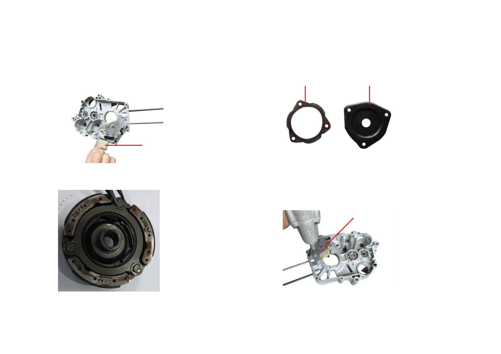
9) Remove the oil strainer on right crankcase assy. and clean it. Replace it if it's
11) Check the auto clutch cover plate and its gasket. Replace them if they're
broken.
broken.
GASKET
CLUTCH COVER PLATE
OIL STRAINER
10) Check the auto clutch body. Replace and clean it if it's broken.
12) Unscrew the tightening screw (M6) of oil pump. (Tightening torque:
8-12N
m)
OIL PUMP
2-66
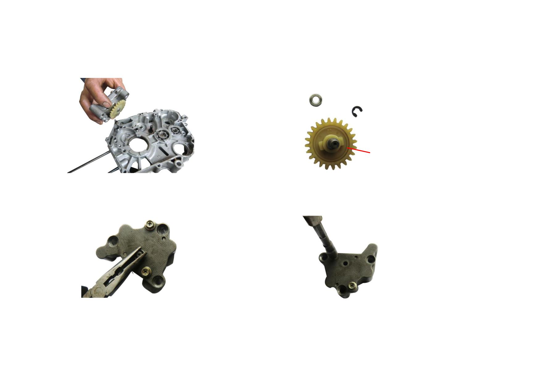
13) Remove the oil pump.
15) Check the drive sprocket, snap ring and washer of oil pump for wear.
Replace them if they're severely worn.
OIL PUMP DRIVE SPROCKET
14) Remove the snap ring of the oil pump drive sprocket.
16) Unscrew the fixing bolts of oil pump.
2-67
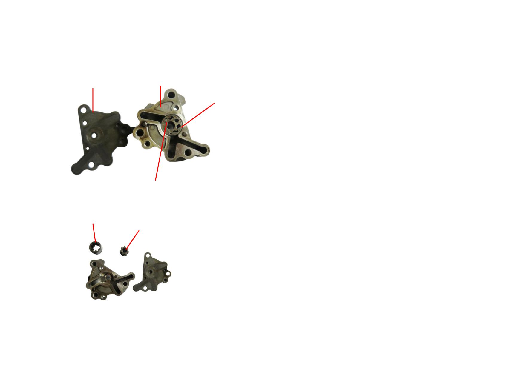
17) Remove the oil pump cover and clean it.
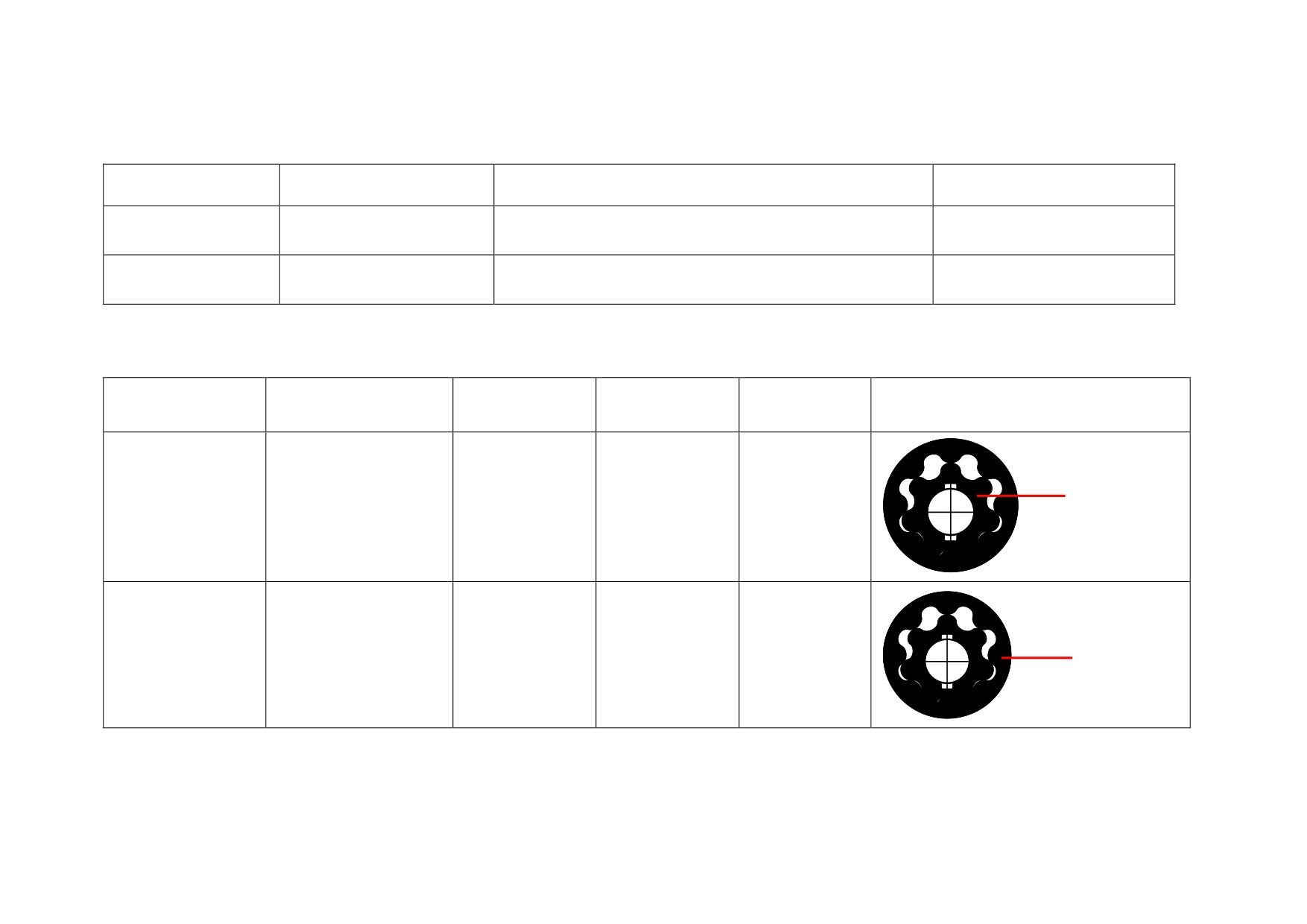
OIL PUMP BODY
OIL PUMP COVER
OIL PUMP OUTER ROTOR
OIL PUMP INNER ROTOR
18) Check the top and bottom cover of oil pump. Replace the oil pump inner
and outer rotors if they are broken or severely worn.
OIL PUMP OUTER ROTOR
OIL PUMP INNER ROTOR
2-68
2.8.2 Troubleshooting to Lubrication System
Description
Cause
Fault
Service
Replace the oil pump drive
Oil pump drive sprocket
Severely worn
Engine lacks power, overheats or is severely worn.
sprocket.
Low oil supply. Engine lacks power or overheats. Parts are
Lubrication system
Oil passages are blocked.
Clean the oil passages.
severely damaged.
2.8.3 Reference List of Standard Value and Service Limit Value for Lubrication System
Description
Test Item
Standard Value
Limit Value
Service
Picture
Replace the oil
GAP TUBE
BETWEEN INNER
Gap between inner and
pump if it
AND OUTER
Oil pump inner rotor
0.05-0.08
0.25
ROTORS
outer rotors
exceeds the
service limit.
Replace the oil
GAP BETWEEN
Gap between outer rotor
pump if it
OUTER ROTOR
Oil pump outer rotor
0.10-0.15
0.30
AND OIL PUMP
and oil pump body
exceeds the
BODY
service limit.
2-69
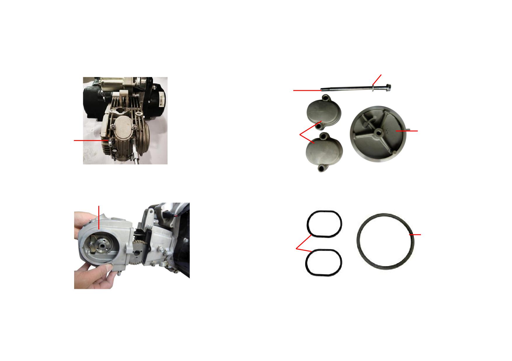
5) Unscrew the engine cap nut M7.
7) Check the cylinder head left cover, valve cover and bolt M6, replace them if
Tightening torque: 12~16N
m
necessary.
BOLT GASKET
BOLT M6
VALVE
LEFT COVER
COVER
CAP NUT M7
6) Remove the cylinder head assembly.
8) Check the gasket and valve cover seal ring, replace them if necessary.
CYLINDER HEAD ASSEMBLY
GASKET
O-RING
2-2
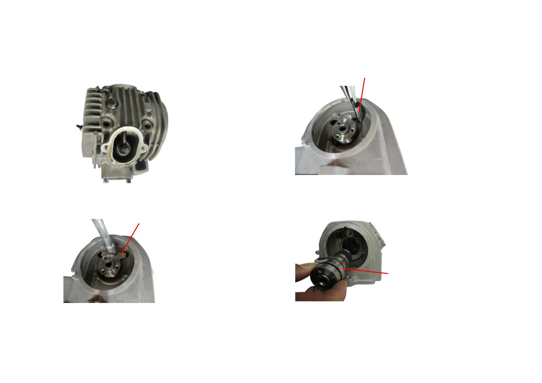
9) Configuration of cylinder head assembly is shown as follows.
11) Remove the rocker arm shaft and valve rocker arm.
ROCKER ARM SHAFT
10) Unscrew and remove the press plate bolt M6 of rocker arm shaft.
12) Remove the camshaft assembly and check it for wear, replace it if
(Tightening torque: 8~12N
m)
necessary.
PRESS PLATE OF ROCKER ARM SHAFT
CAMSHAFT ASSEMBLY
2-3
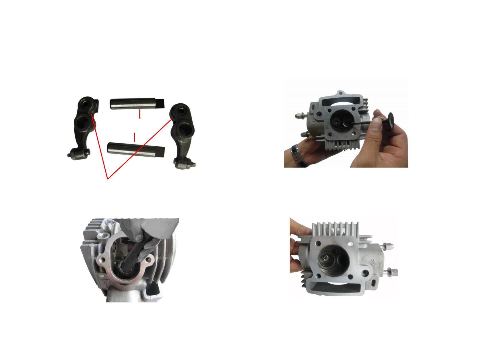
13) Check the intake and exhaust rocker arm and shaft for deformation and wear,
15) Measure the width of valve contact surface, replace the cylinder head and
replace it if shaft OD<Φ9.94mm.
valve if it is beyond the limit (>1.6mm).
VALVE ROCKER
ARM SHAFT
VALVE ROCKER ARM
14) Remove the valve clip, valve spring and valve stem, check for wear and
16) Ream the valve seats to specified values (Φ25±0.05mm, Φ20.5±0.05mm)
replace them if necessary.
and then grind them.
2-4
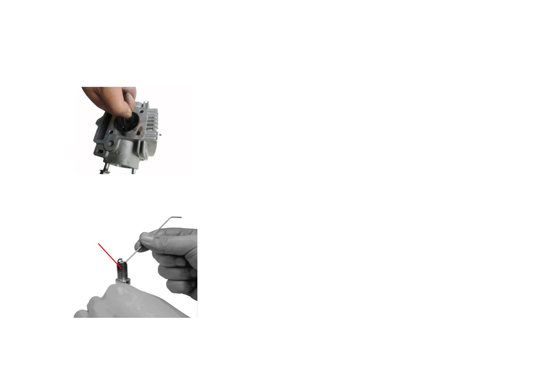
17) Measure the bore of valve guide, replace it if value exceeds the service limit
(>Φ5.03mm).
18) Unscrew the spark plug M10×1, clear carbon deposits on it. Tightening
torque: 10~20N
m
SPARK PLUG
2-5
2.1.2 Troubleshooting to Cylinder Head
Description
Damage Form
Trouble
Service
Too much oil dirt and dusts on the
Poor cooling or overheating engine
Clear away oil dirt and dusts
radiating fins
Carbon deposits in the combustion
Engine overheats
Clear away carbon deposits
chamber
Damaged threaded hole of spark
Air leakage between spark plug and cylinder head,
Repair threaded hole or replace the cylinder
plug
engine fails or is hard to start.
head
Seriously deformation (>0.08mm)
Engine fails or is hard to start. Engine lacks power, has
Grind end surface of cylinder head or replace
of cylinder head end surface
unstable idle speed.
the cylinder head
Defects such as pits, erosion etc. are
Cylinder Head
Engine fails or is hard to start. Engine lacks power, has
found on the contact area of valve
Grind valve seats and valves
unstable idle speed.
seats
Valve leaks due to eccentric grinding of valve seats,
Valve guide bore is worn seriously
making the engine difficult to start and unstable at idle
Replace valve guide or cylinder head
(>5.03mm)
speed.
Engine fails or is hard to start. Engine lacks power, has
Damaged cylinder head gasket
Replace cylinder head gasket
unstable idle speed.
Engine fails or is hard to start. Engine lacks power, has
Loose cylinder head locknut
Tighten up locknut
unstable idle speed.
2-6
Engine fails or is hard to start. Engine lacks power, has
Adjust by slightly bend the side electrode till
Improper gap between two electrodes
unstable idle speed.
the gap is 0.65-0.75 mm
Electrodes link by carbon deposits
Engine fails to start.
Clear away carbon deposits
Too much carbon deposits or oil dirt
Engine fails or is hard to start. Engine lacks power, has
Clear away carbon deposits or oil dirt
Spark Plug
around the spark plug
unstable idle speed.
Engine fails or is hard to start. Engine lacks power, has
Replace with a new spark plug in the same
Damaged spark plug insulator
unstable idle speed.
model
Loose spark plug
Engine is hard to start, or has unstable idle speed.
Tighten up the spark plug
2-7
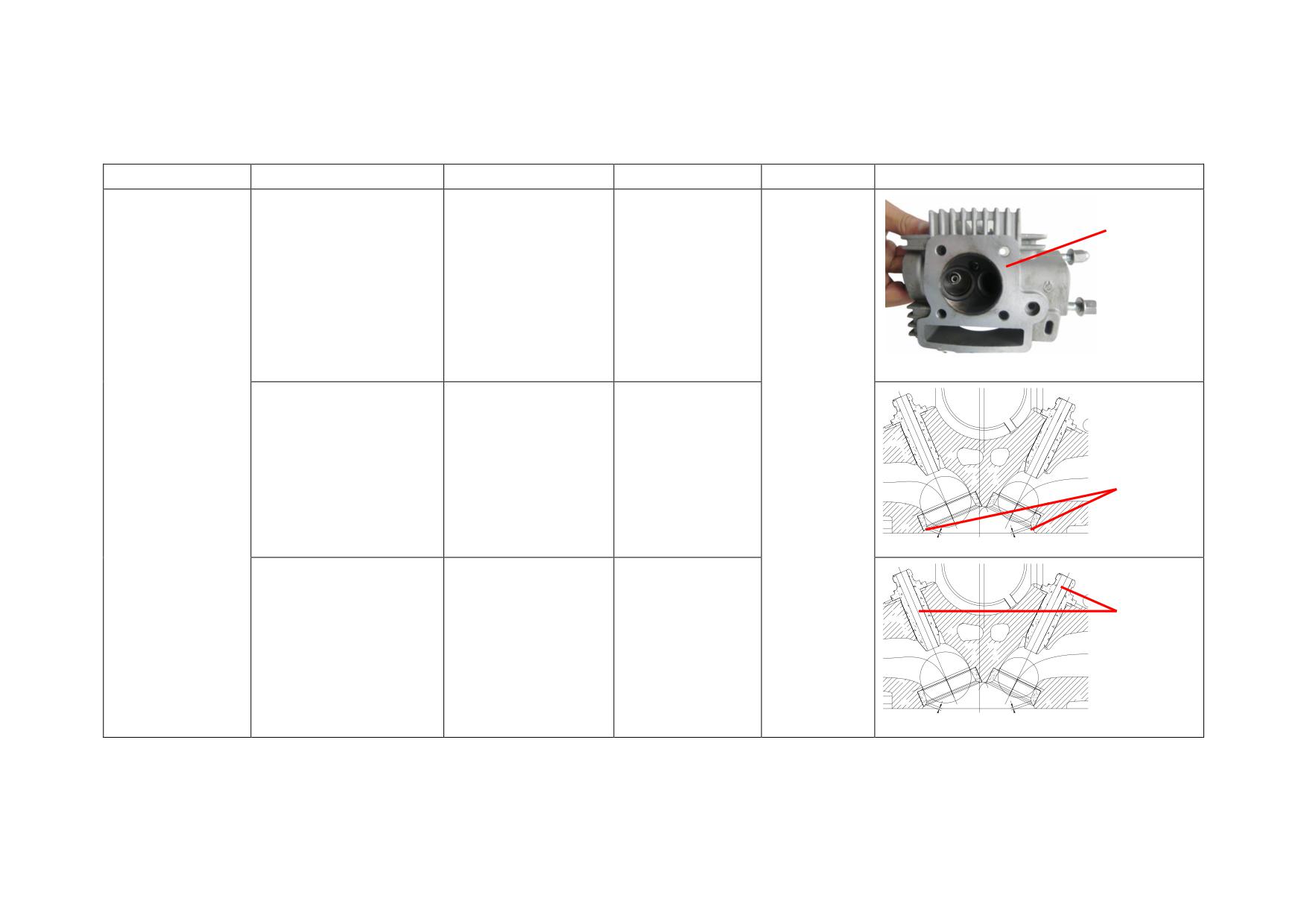
2.1.3 Reference List of Standard Value and List Value for Cylinder Head Maintenance
Description
Test Item
Standard Value
Limit Value
Service
Picture
Flatness
Flatness of cylinder face
0~0.05
0.08
Width of
Replace when
valve seat
Width of valve seat
Cylinder Head
beyond the
0.9~1.1
1.4
sealing face
sealing face
limit value
Diameter
of valve
guide
Diameter of valve guide
Φ5~Φ5.012
Φ5.03
bore
bore
2-8
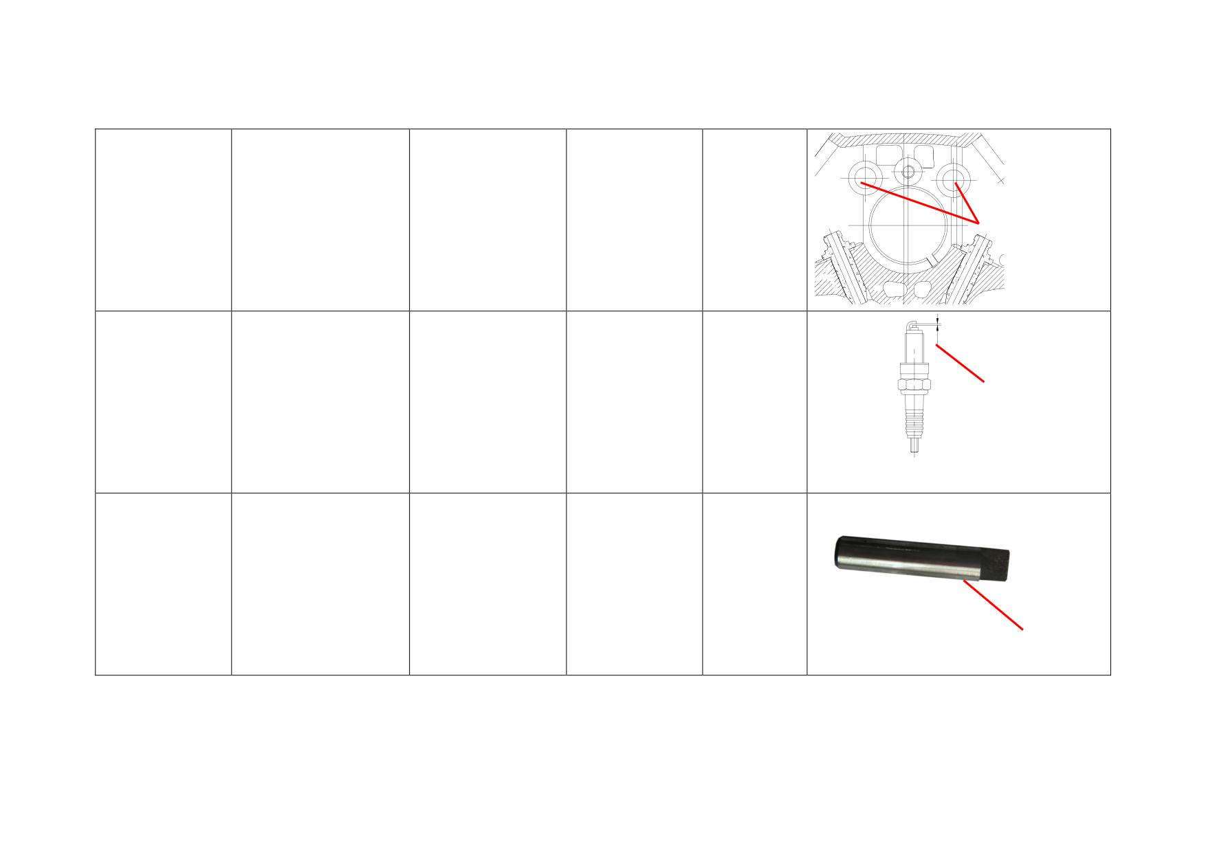
Replace when
Diameter of
Diameter of rocker arm
Cylinder Head
Φ10~Φ10.022
Φ10.05
beyond the
rocker arm
shaft bore
limit value
shaft bore
Spark plug
Adjust gap
gap
Spark Plug
Spark plug gap
0.8~0.9
1
when beyond
the limit value
Replace when
Rocker Arm Shaft
OD of rocker arm shaft
Φ9.972~Φ9.987
Φ9.94
beyond the
OD of
limit value
rocker arm
shaft
2-9
CHAPTER 3 CHASSIS
3.1 FRAME BODY
3.1.1 Motorcycle Identification
3.1.2 Maintenance of Frame
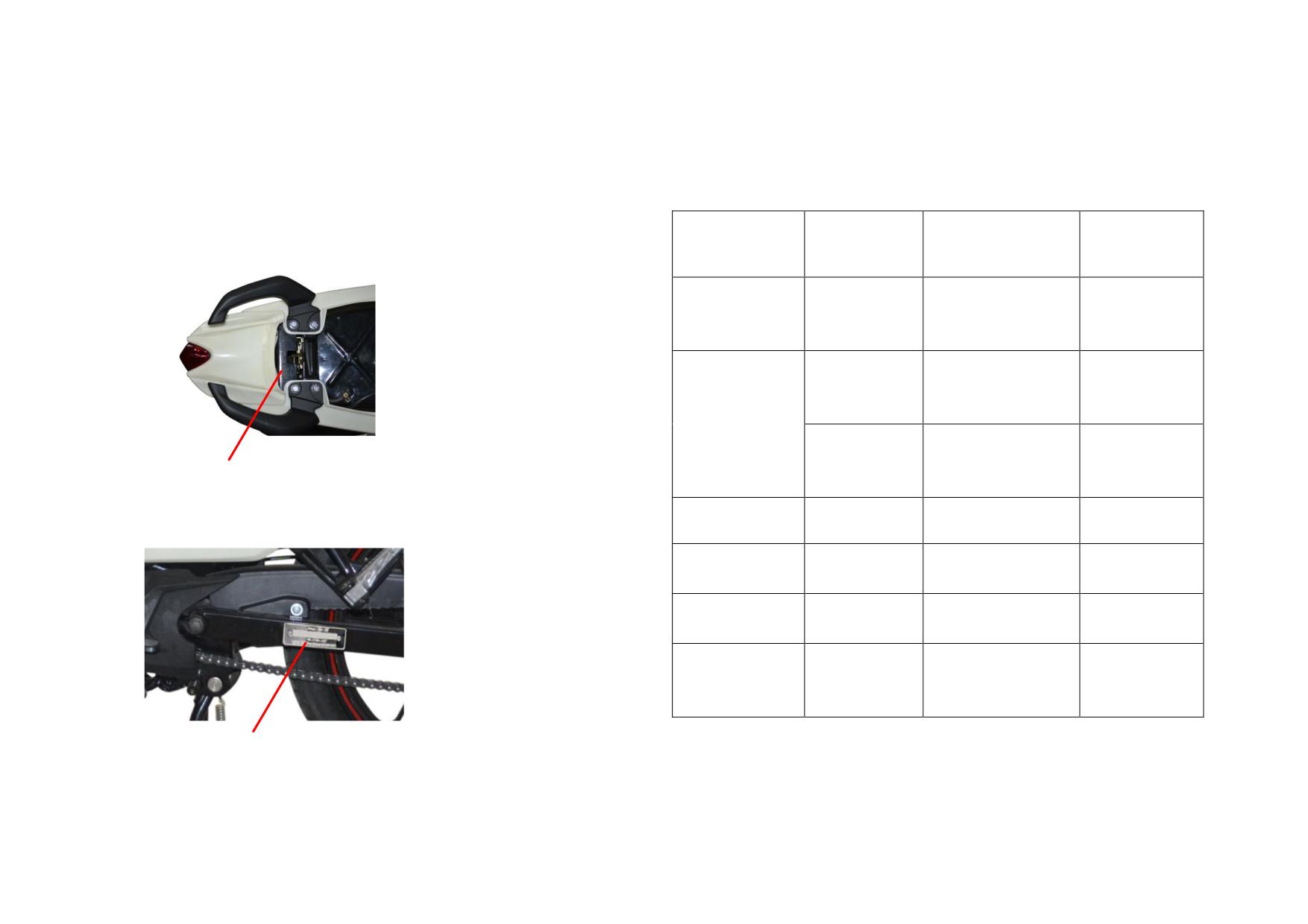
1) VIN
The vehicle identification number (VIN) is engraved on
Description
Damage Form
Trouble
Service
the upper face of handrail mounting bracket.
Correct or
Deformed or
Frame
Off-tracking
replace the
broken
frame
Replace the
Deformed or
Effect on parking
center (side)
broken
Center (side)
stand
stand
Center (side) stand
Damaged
Replace the
fails to return.
VIN
return spring
return spring
Effect on parking
2) Frame Nameplate
Covering parts
Broken
Effect on appearance
Replace
The frame nameplate is fixed in the rear fork.
Replace the
Fender
Damaged
Effect on fending
fender
Replace the seat
Seat cushion
Broken
Decrease comfort
cushion
Deformed footrest or
Correct or
Deformed or
Footrest
broken footrest
replace the
broken
rubber
footrest rubber
FRAME NAMEPLATE
3-1
3.1.3 Maintenance of Frame and Accessories
Removal, Installation and Maintenance
3) Adjust the travel of rear brake pedal at the rear brake level if travel exceeds
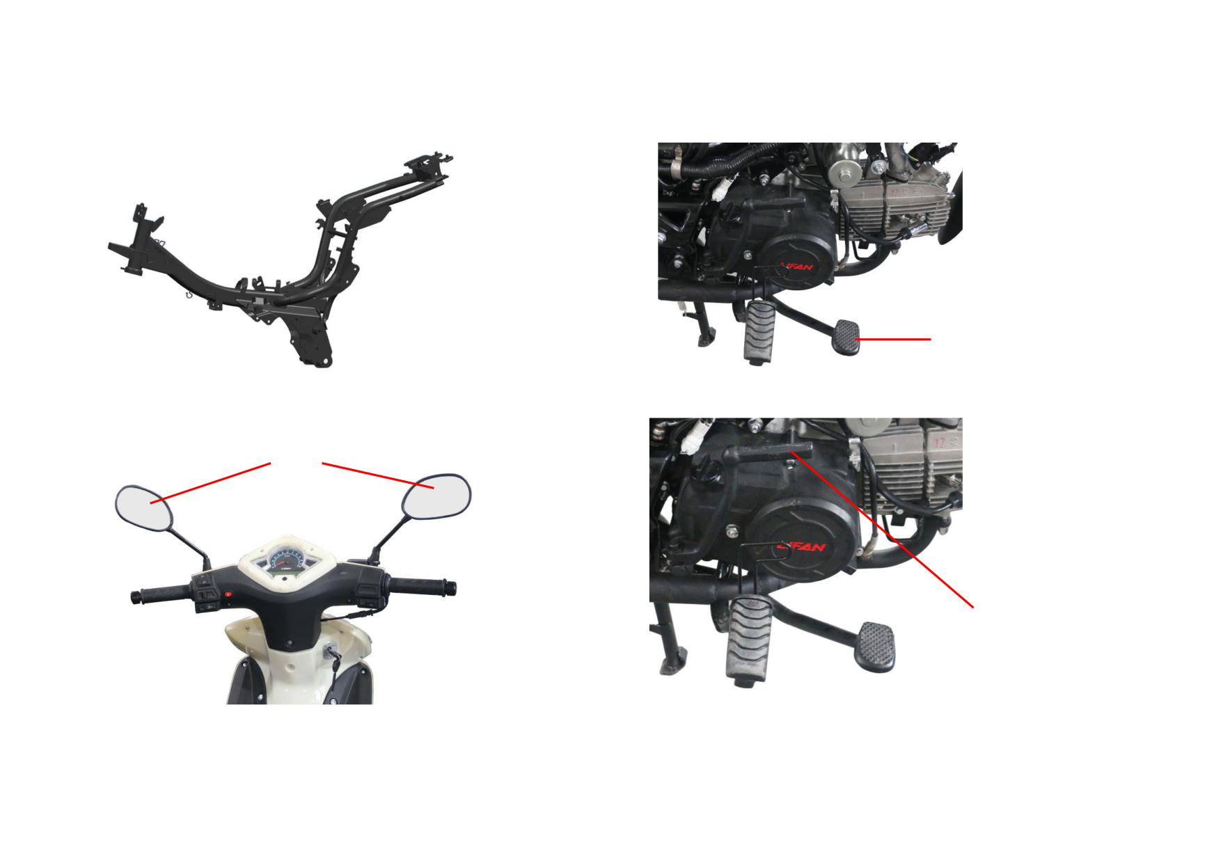
1) Structure of frame is shown below. Check the welding parts and frame.
the service limit (20~30mm).
REAR BRAKE PEDAL
2) Check the rear-view mirror for looseness, tighten up the mirror and wipe the
4) Check the starting rod for break, repair or replace it if necessary.
mirror surface.
REAR-VIEW MIRROR
STARTING ROD
3-2
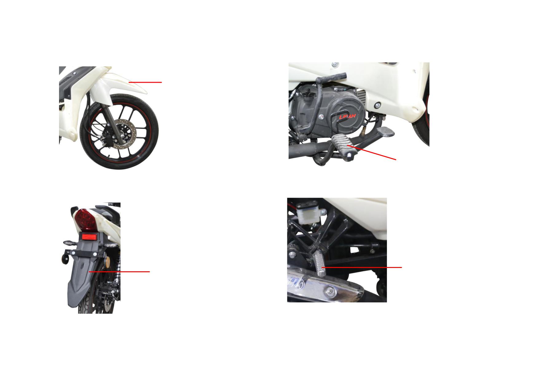
5) Check the front fender for break, replace it if necessary.
7) Check the front footrest pedal for damage, replace it if necessary.
FRONT FENDER
FRONT FOOTREST PEDAL
6) Check the rear fender for break, replace it if necessary.
8) Check the rear footrest pedal for damage, replace it if necessary.
REAR FOOTREST PEDAL
REAR FENDER
3-3
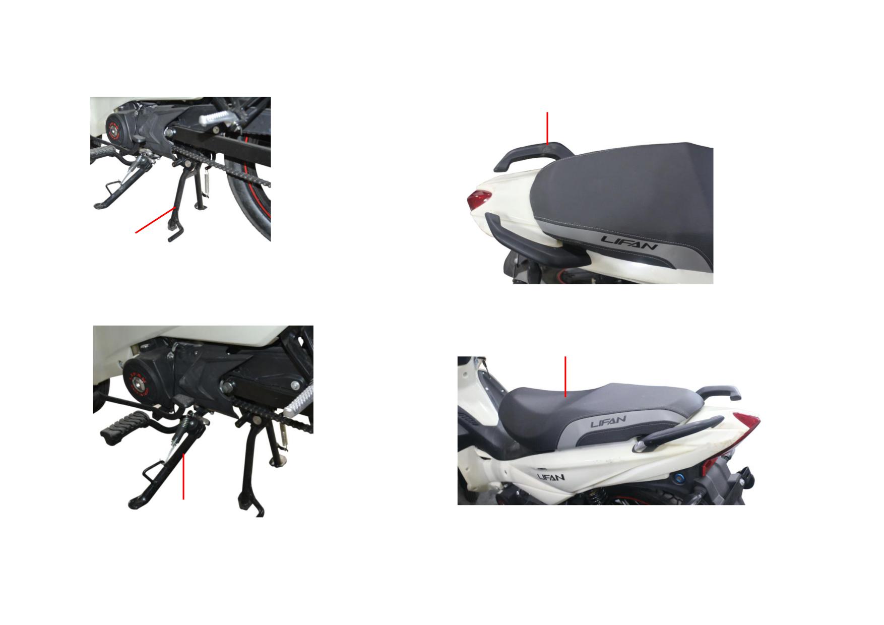
9) Check the center stand for deformation, replace it if necessary.
11) Check the handrail for break, replace it if necessary.
HANDRAIL
CENTER STAND
10) Check the side stand for deformation, replace it if necessary.
12) Check the seat cushion for break, replace it if necessary.
SEAT CUSHION
SIDE STAND
3-4
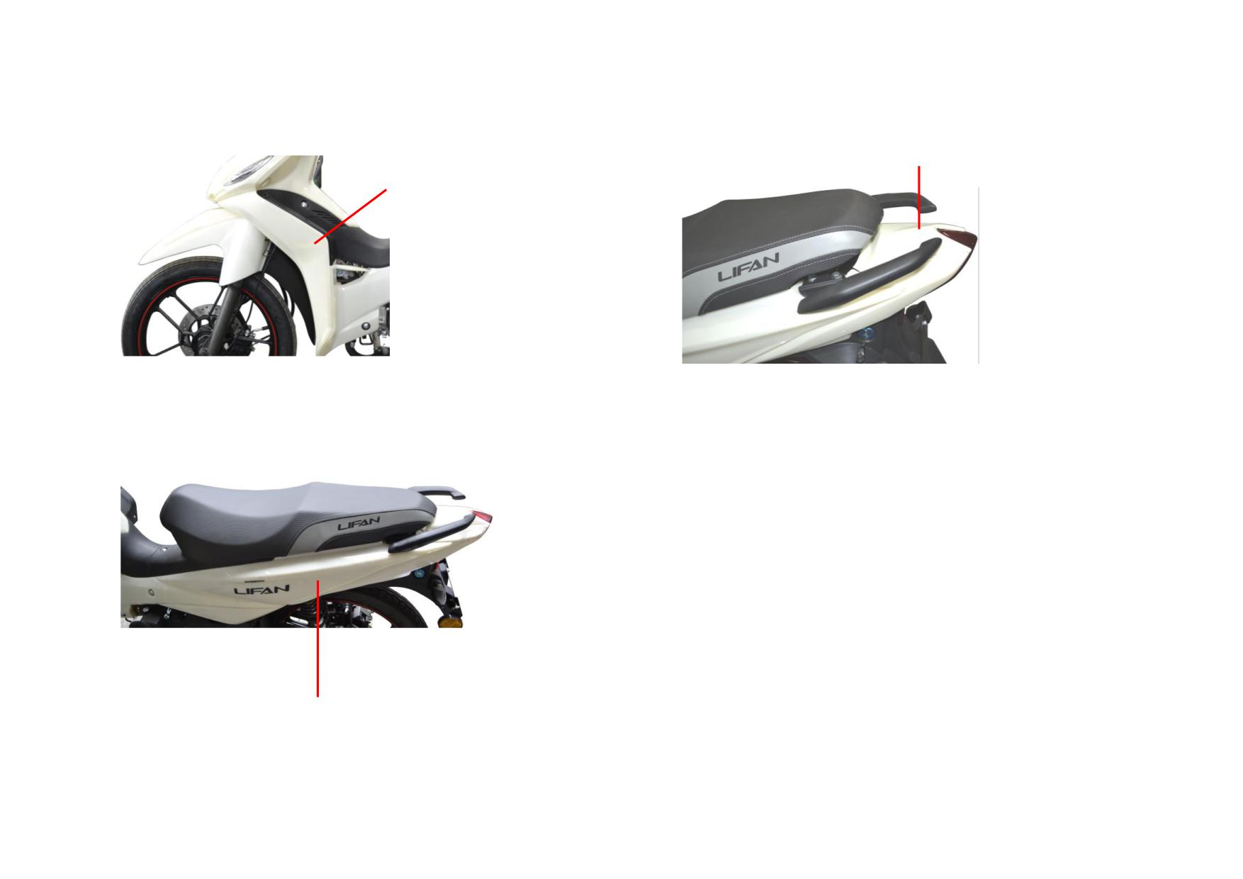
13) Check the windshield for break, replace it if necessary.
15) Check the rear-mid connecting plate for break, replace it if necessary.
REAR-MID CONNECTING PLATE
WINDSHIELD
14) Check the rear panel for break, replace it if necessary.
REAR PANEL
3-5

3.2 SUSPENSION SYSTEM
3. 2.1 Removal, Installation and Maintenance of Steering Bar
1) Turn the steering bar and check it for proper functioning.
3) Disassemble the steering bar pipe and check it for deformation, correct or
replace it if necessary.
HANDLE
2) If necessary, disassemble the steering system to check.
4) Unscrew the steering stem locknut.
LOCKNUT
3-6
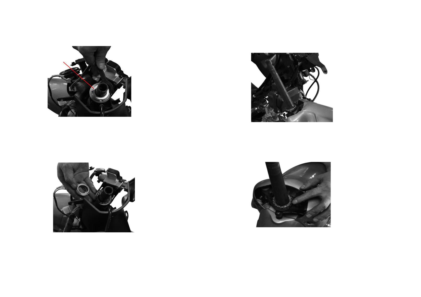
5) Unscrew the adjusting nut of steering stem.
7) Extract the steering stem, check the top cover and bottom race of lower
bearing of steering stem for wear, replace it if necessary.
NUT
6) Check the top cover and bottom race of upper bearing of steering stem for
8) Before installing the steering stem, apply a layer of grease to the top cover
wear, replace the bearing if necessary.
and bottom race of lower bearing.
3-7
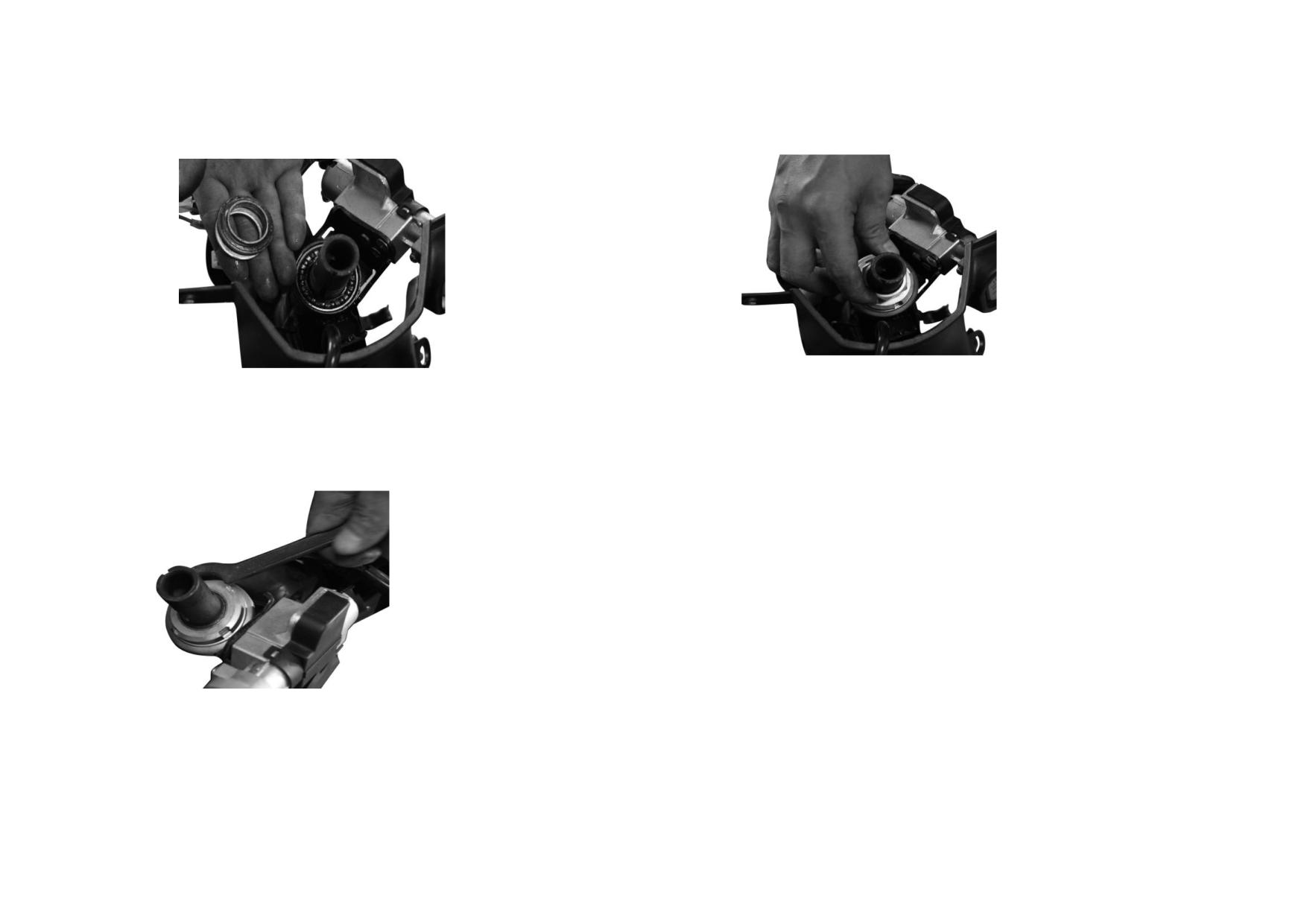
9) Before installing the steering stem, apply a layer of grease to the top cover
11) Tighten up the steering stem locknut.
and bottom race of upper bearing.
10) Tighten up the steering stem locknut.
3-8
3.2.2 Troubleshooting to Steering Stem
Description
Damage Form
Trouble
Service
Operation of steering handle is stiff ; little
Turn the adjusting nut by a wrench until the
Adjusting nut of steering stem is over
gaps between bearing and upper cover,
steering stem turns flexibly without radial play
tightened
bearing and bottom race
between steering stem and riser.
Bearing bottom race
The steel ball trail of bottom race is worn
Operation of steering handle is stiff with
out, defects such as pits, dints, cracks are
Replace the bearing bottom race
shaking and vibration.
found.
The steel ball is worn, deformed or
Operation of steering handle is stiff with
Bearing
Replace the bearing as a set
damaged.
shaking and vibration.
Operation of steering handle is stiff with
Steering stem
Deformed
Replace the steering stem
shaking and vibration.
3-9
3.3 FRONT SUSPENSION
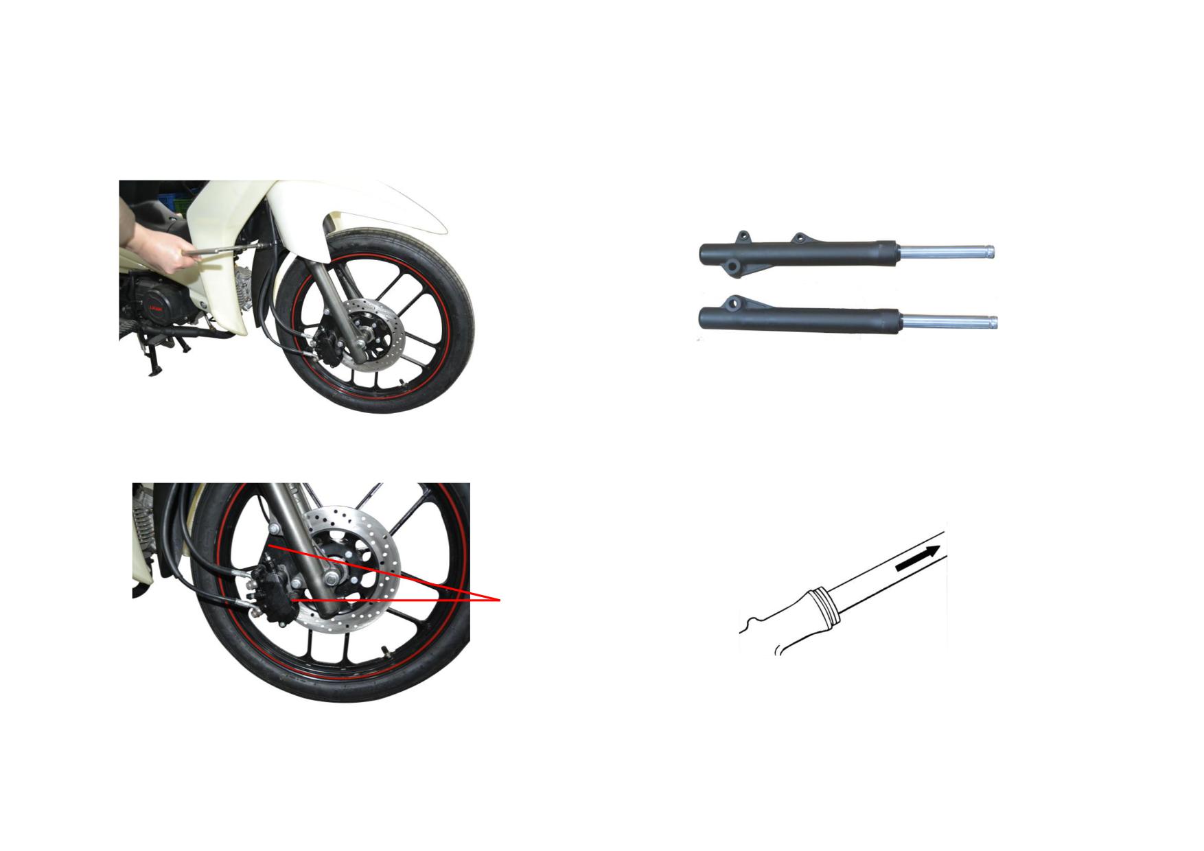
3.3.1 Removal, Installation and Maintenance of Front Suspension
1) Unscrew the fixing bolt of brake hose from the front fender.
3) Remove the front fender and front shock absorber.
2) Unscrew the locknut of front axle and fixing bolt of brake caliper, pull out
4) Unscrew the drain bolt from the front shock absorber and drain the damping
the front axle and remove the front wheel.
oil. Check and replace the oil if necessary.
BOLT
3-10
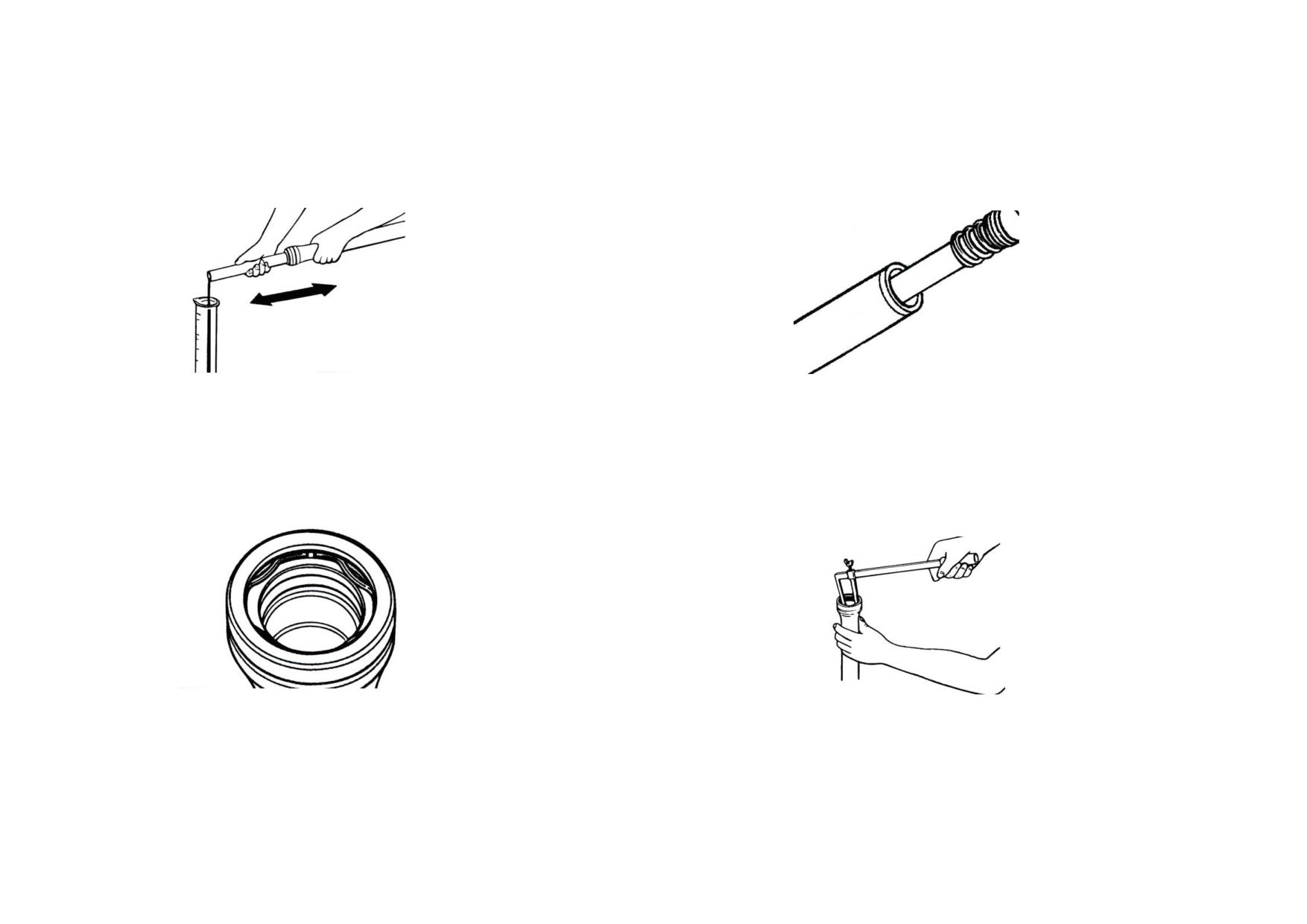
5) Remove the dust cover and clip, extract the bottom case.
7) Extract and check the damping spring for wear, replace it if necessary.
6) Remove and check the oil seal for wear, replace it if necessary.
8) Measure the inner diameter of bottom case, replace it if it exceeds its service
limit.
3-11
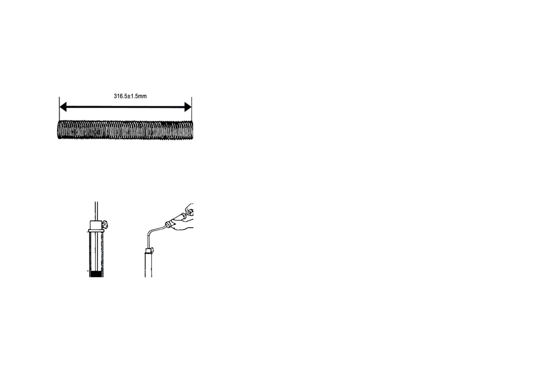
9) Measure the free length of shock absorber spring, replace it if it is out of the
service limit 316.5±1.5 mm.
10) Pour about 60±1ml damping oil into the tube.
3-12
3.3.2 Troubleshooting to Front Shock Absorber
Description
Damage Form
Trouble
Service
The front shock absorber is too soft or
Front shock absorber
Non-elastic or broken
abnormal sound comes out of the bottom
Replace the spring
spring
case
Bent or deformed
Off-track in running
Correct or replace the front shock absorber
Damaged or scratched working
Front fork tube
Oil leaks from the oil seal
Replace the front fork tube
surface
The chromium-plated parts are worn
Oil leaks from the oil seal
Replace the front fork tube
with the substrate exposed.
Bottom case
Broken, deformed or damaged
Oil leaks from the bottom case.
Replace the bottom case
Heavily worn or damaged
The front shock absorber is too soft.
Replace the piston rod
Piston rod
Piston rings are heavily worn or
The front shock absorber is too soft.
Replace the piston rod
damaged
Oil seal
Heavily worn, damaged or aged
Oil leaks from the front shock absorber
Replace the oil seal
Damping oil
Lack of oil
The front shock absorber is too soft.
Fill damping oil as per the specification (60±1ml)
3-13
3.4 REAR SUSPENSION
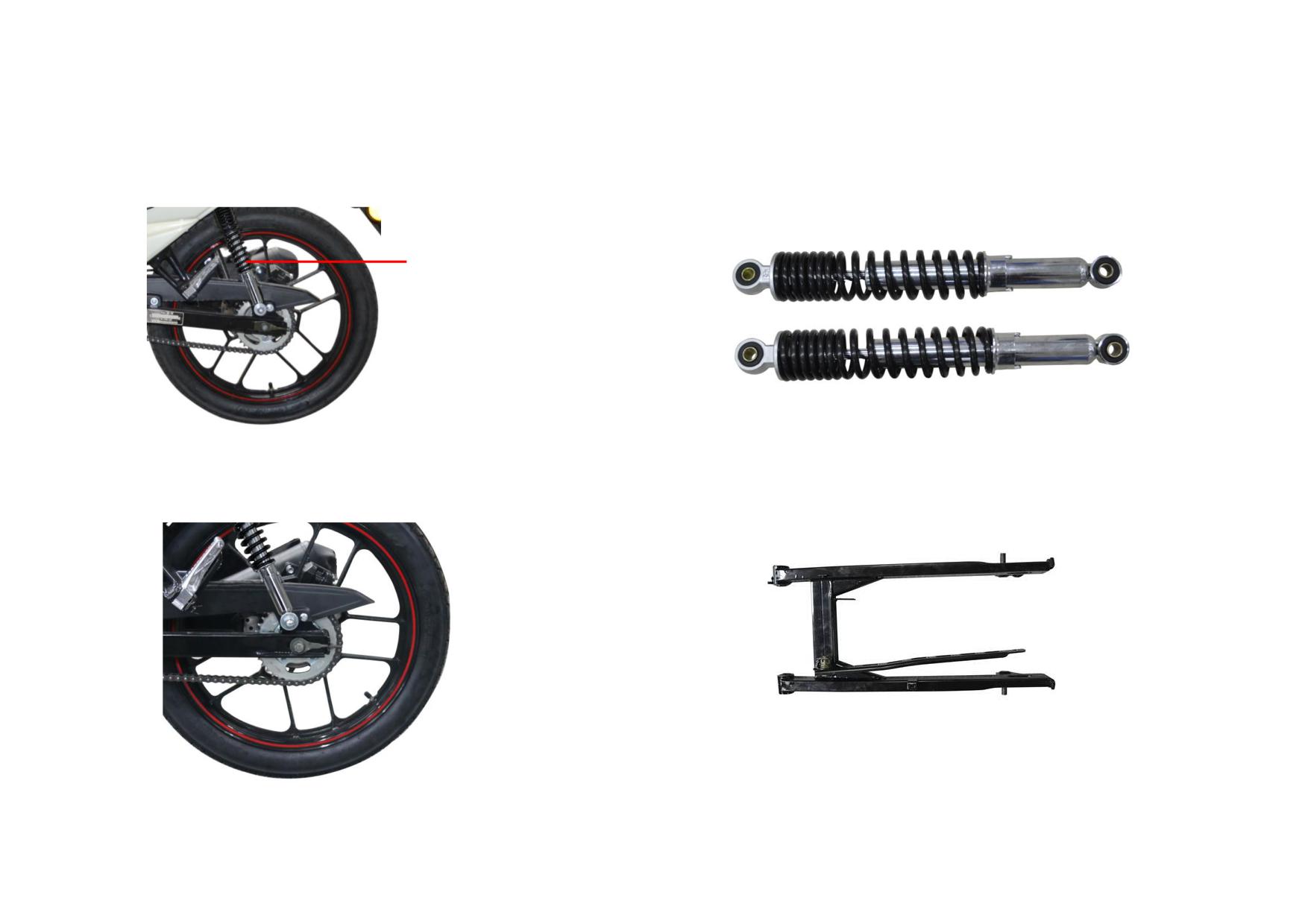
3.4.1 Removal, Installation and Maintenance of Rear Suspension
1) Check the rear wheel for swing, adjust or replace the rear fork sleeve if
3) Check the rear shock absorber spring; check the rear shock absorber for oil
necessary.
leakage, replace them if necessary.
REAR SHOCK ABSORBER
2) Unscrew the locknut from the rear shock absorber, check the sleeve boot for
4) Unscrew the locknut from the rear axle, check the rear fork sleeve for wear,
wear, replace it if necessary.
replace the fork if necessary.
3-14
3.4.2 Troubleshooting to Rear Suspension
Description
Damage Form
Trouble
Service
The spring is non-elastic or broken.
The rear shock absorber is too soft.
Replace the spring
Rear shock absorber
Oil leaks from the rear shock absorber.
The rear shock absorber is too soft.
Replace the rear shock absorber
The piston rod is bent, deformed or
The rear shock absorber is hard.
Replace the rear shock absorber
broken.
Deformed
Off-track in running
Correct or replace the rear fork
Rear fork
Cracked
Unable driving
Weld or replace the rear fork
3-15
3.5 FRONT AND REAR WHEELS
3.5.1 Maintenance of Wheels
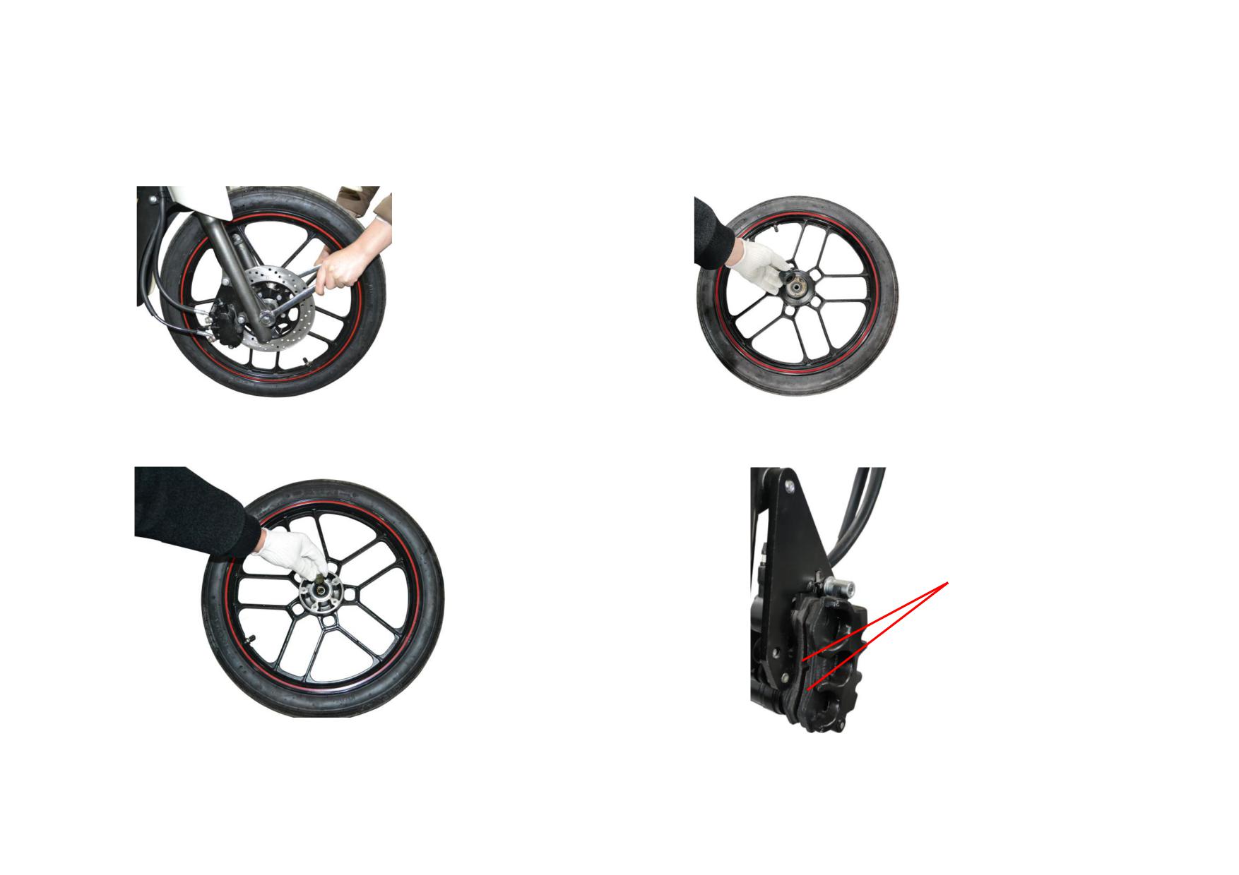
1) Unscrew the front axle locknut to remove the front wheel.
3) Check the speedometer seal ring for wear, replace it if necessary.
2) Remove and check the front axle bush for wear, replace it if necessary.
4) Check the brake shoes for wear, replace the shoes as a set if necessary.
BRAKE SHOES
3-16
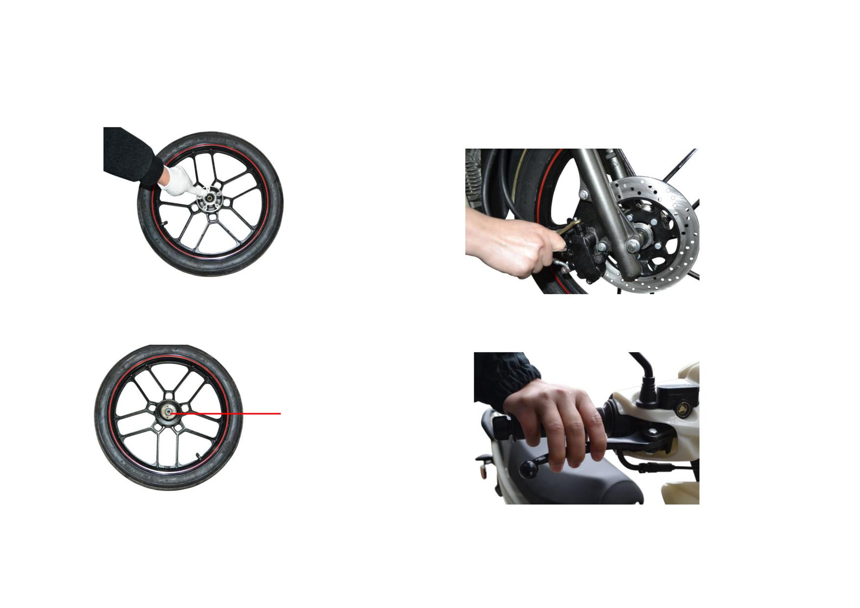
5) Remove and check the front axle oil seal for wear, replace it if necessary.
7) Remove the rubber dust cover of drain hose of front brake caliper, loosen the
locknut; hold the front brake lever, and tighten the locknut until oil comes out
from the drain hose (while not releasing the front brake lever).
6) Check the front axle bearing for wear, replace it if necessary.
8) Repeatedly hold and release the front brake lever to test if the front brake
force reaches 200N.
BEARING
3-17
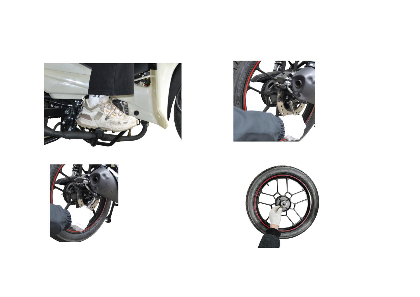
9) Finally, repeatedly step and release the rear brake pedal until the operation
11) Unscrew the adjusting nut from the chain adjuster and pull out the rear axle.
force is suitable (less than 350N).
10) Unscrew the locknut from the rear axle.
12) Remove the rear axle bush and oil seal, check the oil seal and replace it if
necessary.
3-18
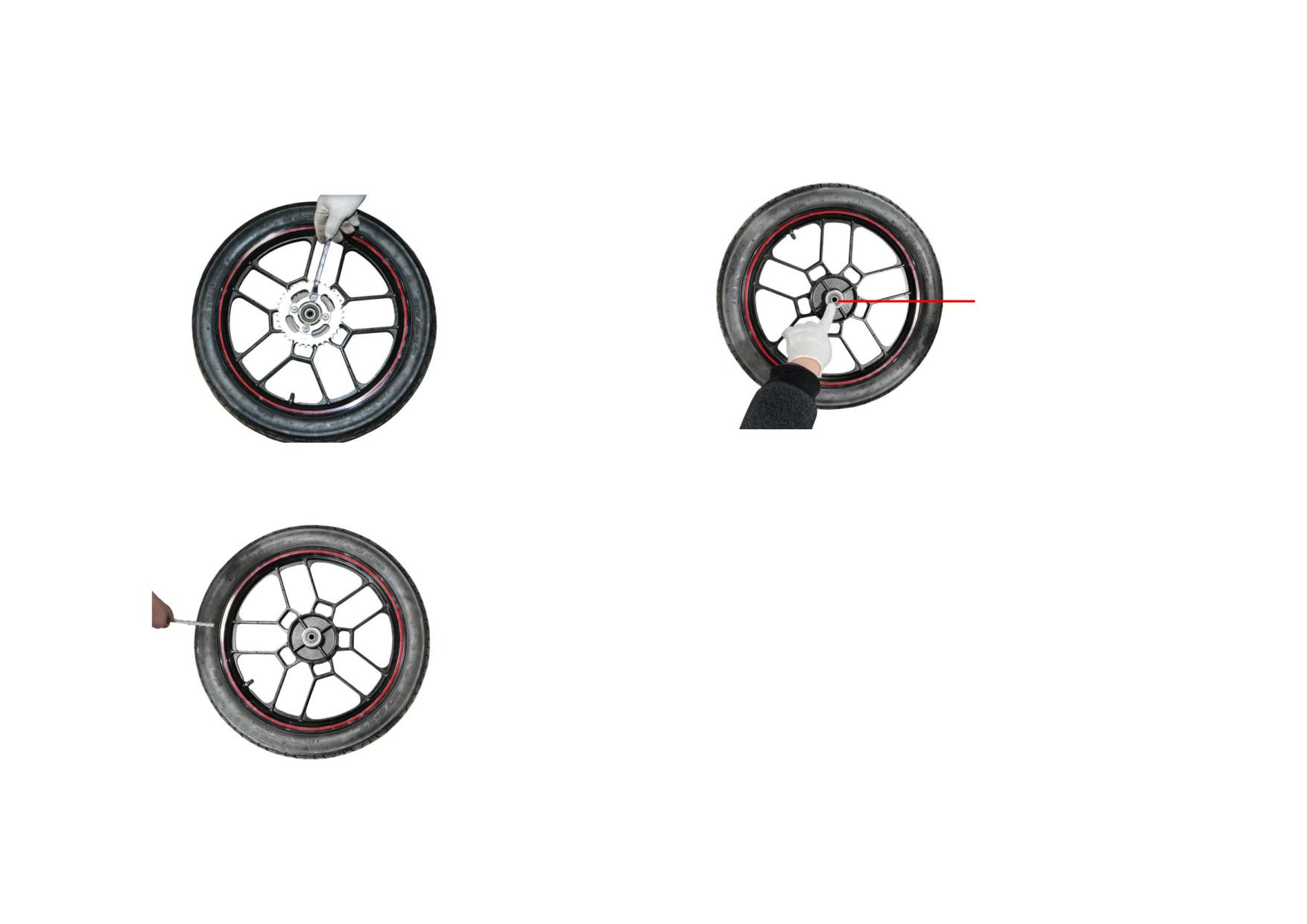
13) Unscrew the nut from the sprocket hub assembly, remove and check it for
15) Check the bearing of rear axle for wear, replace it if necessary.
wear, replace it if necessary.
BEARING
14) Check the tyre for wear, replace it if it exceeds 2mm of the service limit.
3-19
3.5.2 Troubleshooting to Front and Rear Wheels
Description
Damage Form
Trouble
Service
Shortened service life of bearing, incorrect
Front axle oil seal is worn.
Replace the front axle oil seal
count of speedometer
Front wheel
Brake shoes are worn.
Decreased braking effect
Replace the brake shoes
Discharge air in the front hydraulic brake as specified in
Poor braking performance
Weak braking effect of front hydraulic brake
3.5.1
Rear axle oil seal is worn.
Shortened service life of bearing
Replace the rear axle oil seal
Rear wheel
Surface of brake drum is worn.
Decreased braking force
Replace the rear wheel hub
Brake
Brake shoes are worn.
Decreased braking force
Replace the brake shoes
3-20
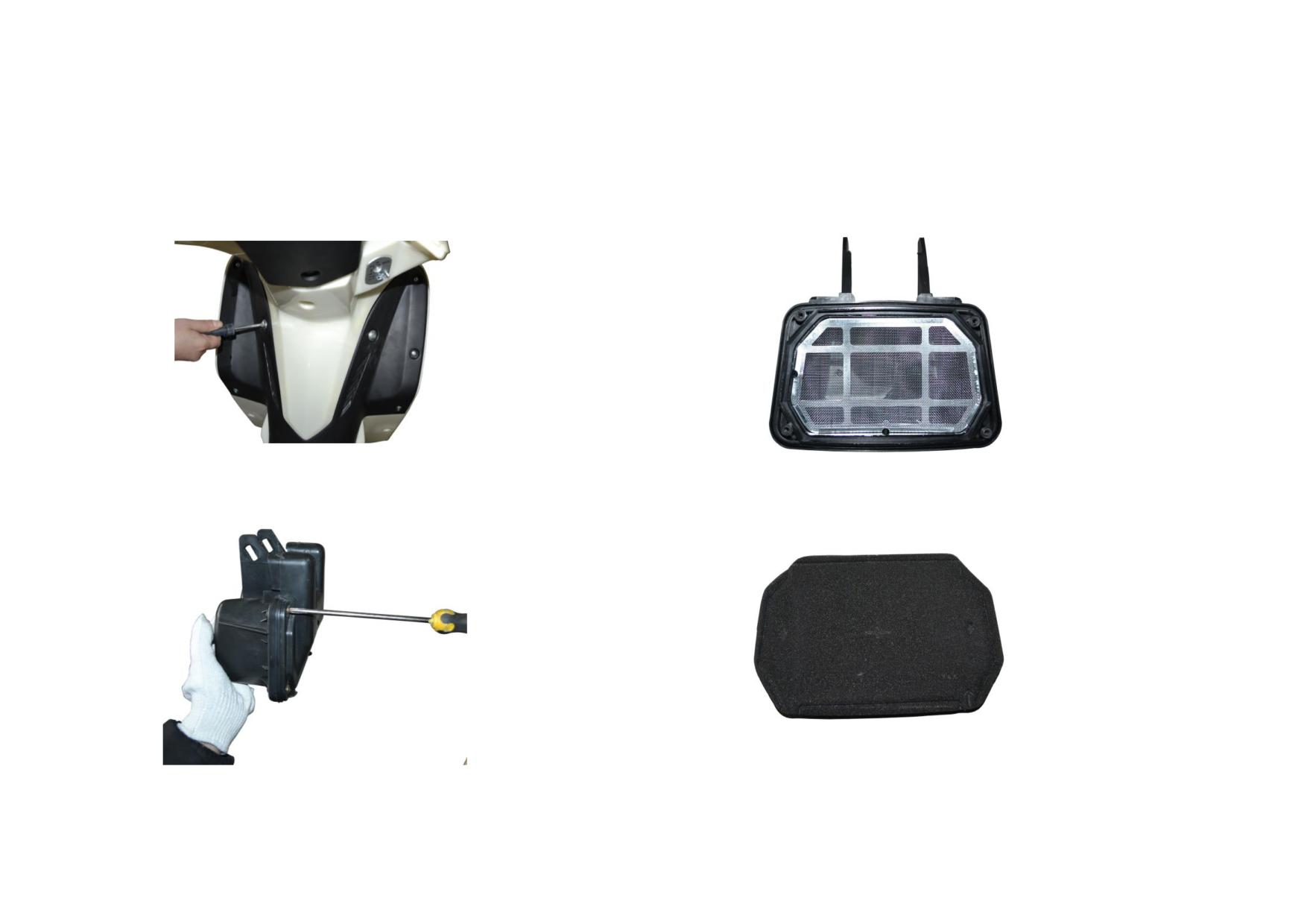
3.6 INTAKE SYSTEM AND EXHAUST SYSTEM
3.6.1 Removal, Installation and Maintenance of Intake System
1) Unscrew the mounting screw to remove the windshield, and disassemble the
3) Remove and check the air cleaner filter strainer for damage, replace it if
air cleaner.
necessary.
2) Unscrew the screw to remove the air cleaner cover.
4) Clear away dust on the air cleaner element, replace it if necessary.
3-21
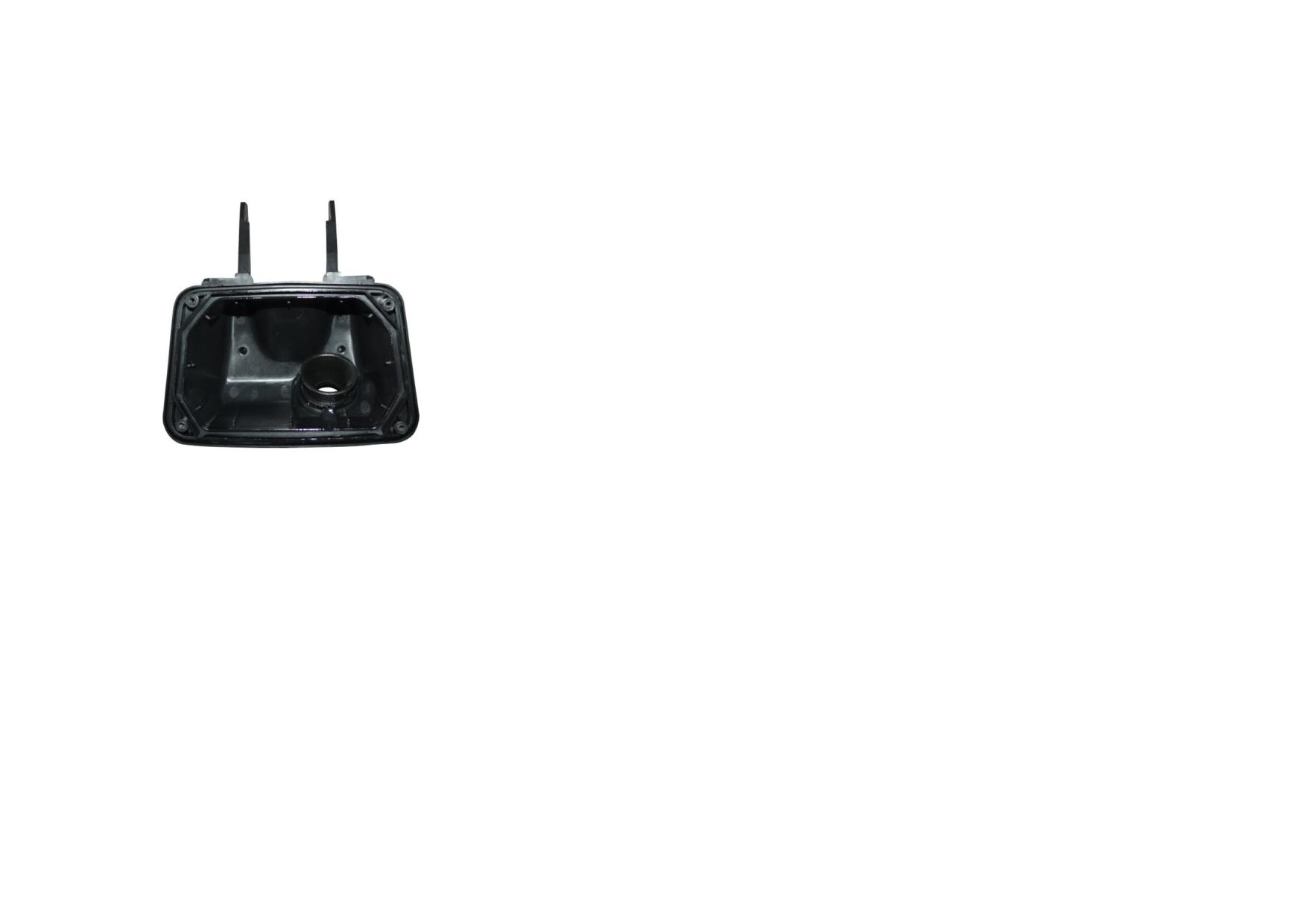
5) Check the air cleaner housing, clear away dust on it and replace it
if necessary.
3-22
3.6.2 Troubleshooting to Air Cleaner
Description
Damage Form
Trouble
Service
Remark
1. Remove the air cleaner element as 3.6.1;
Engine is hard to start, engine lacks
2. Blow the dust on the element surface off, replace
Too much dust on the
power, poor performance at idle
Do not clean it with
the element if necessary;
element
speed; too much fuel consumption,
water or oil
3. Reinstall the air cleaner element and cover in the
Air cleaner
thick smoke from the exhaust pipe
reverse order of disassembly.
Loud noise from the engine intake
Broken element
Replace the element
system
3-23
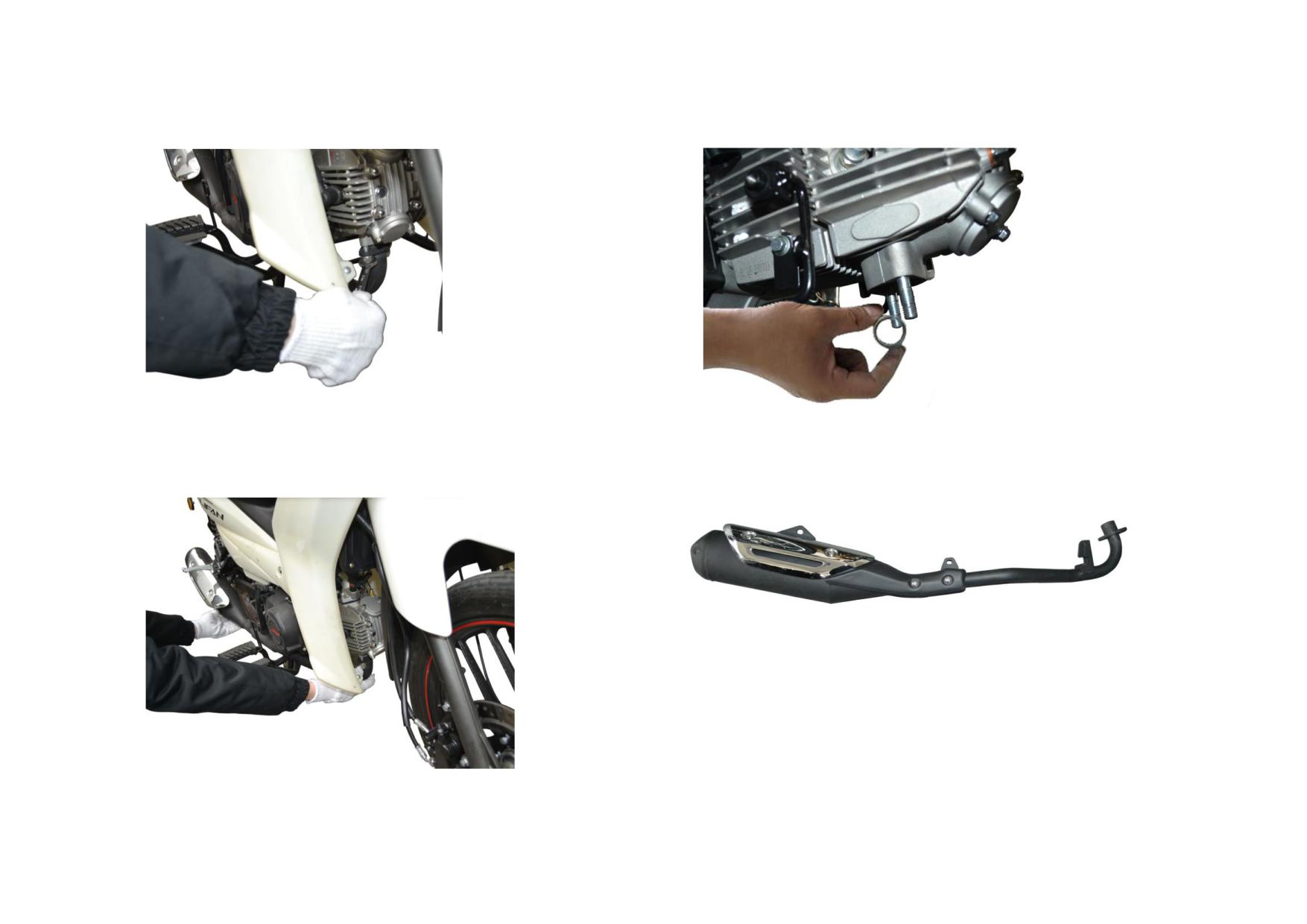
3.6.3 Removal, Installation and Maintenance of Exhaust System
1) Unscrew the fixing nut that connects the exhaust muffler with the engine.
3) Check the exhaust muffler gasket, replace it if necessary.
2) Remove the exhaust muffler, check the mounting plate for break, repair or
4) Shake the exhaust muffler and check the interior, replace it if necessary.
replace it if necessary.
3-24
3.6.4 Troubleshooting to Exhaust Muffler
Description
Damage Form
Trouble
Service
Remark
Exhaust muffler
Loud noises from the exhaust
Replace the gasket after each
Broken gasket
Replace the muffler gasket
gasket
system, air leaks from the pipe.
disassembly
Broken muffler housing
Loud noises from the exhaust
Replace the exhaust muffler
and mounting bracket
system
Desoldering and loose
Abnormal sound in the exhaust
Exhaust muffler
Replace the exhaust muffler
internal components
muffler
Decreased engine performance
Carbon deposits in the
Clean off carbon deposits with
raises the combustion gas
exhaust pipe
genuine cleansing solvent
discharge resistance
3-25
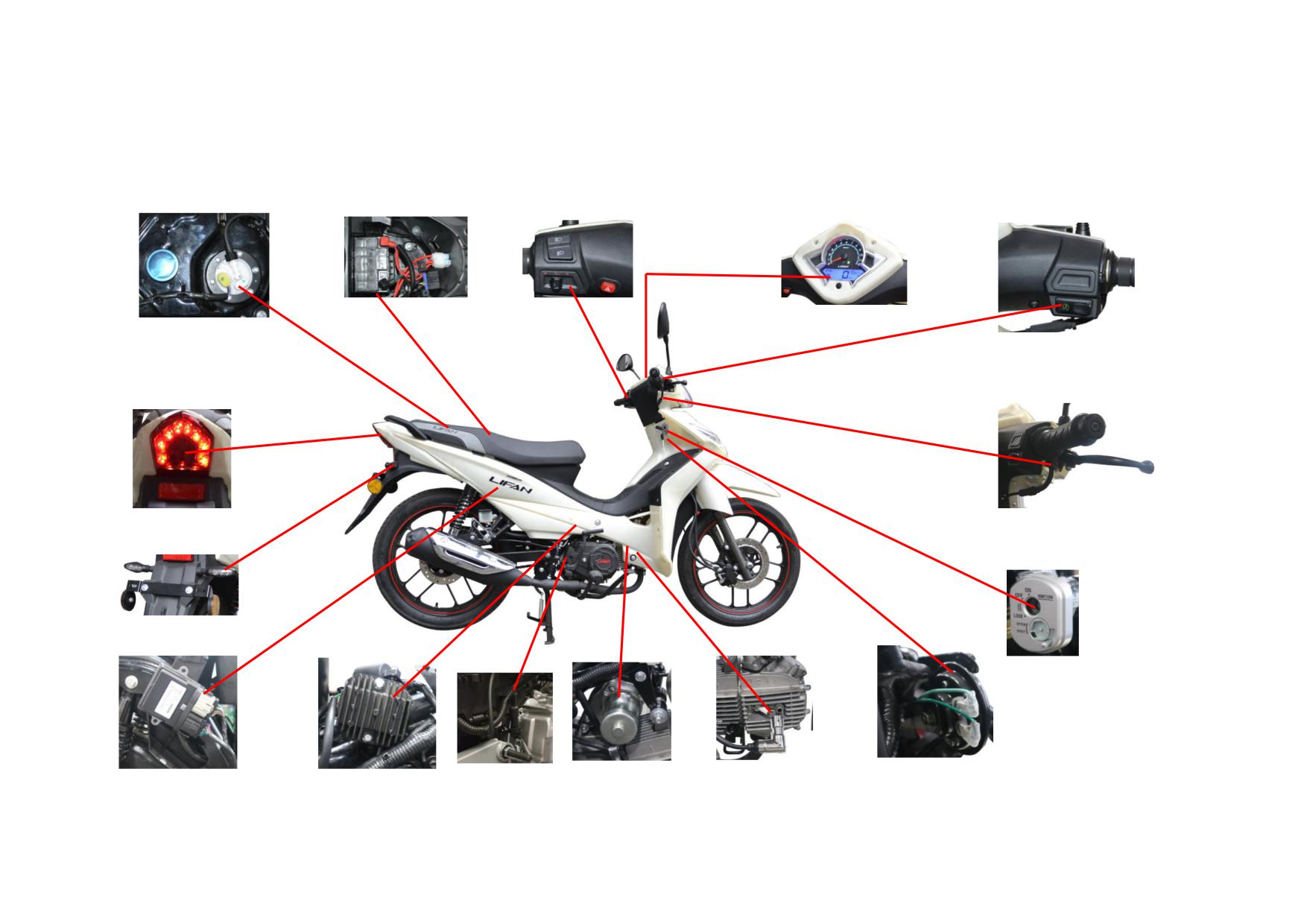
CHAPTER 4 ELECTRICAL COMPONENTS AND METER
●Location Distribution of Electrical Components on The Vehicle
FUEL PUMP&FUEL SENSOR
BATTERY&FUSE BOX
DIMMER/TURN SIGNAL/EMERGENCY/HORN SW
METER
STARTER BUTTON
FR. BRAKE SW.
TAILLIGHT&RR. REFLECTOR
RR. WINKER, LH/RH
IGNITION SW.
ECU
RECTIFIER
RR. BRAKE SW.
STARTING MOTOR
SPARK PLUG&SPARK PLUG CAP
HORN
4-1
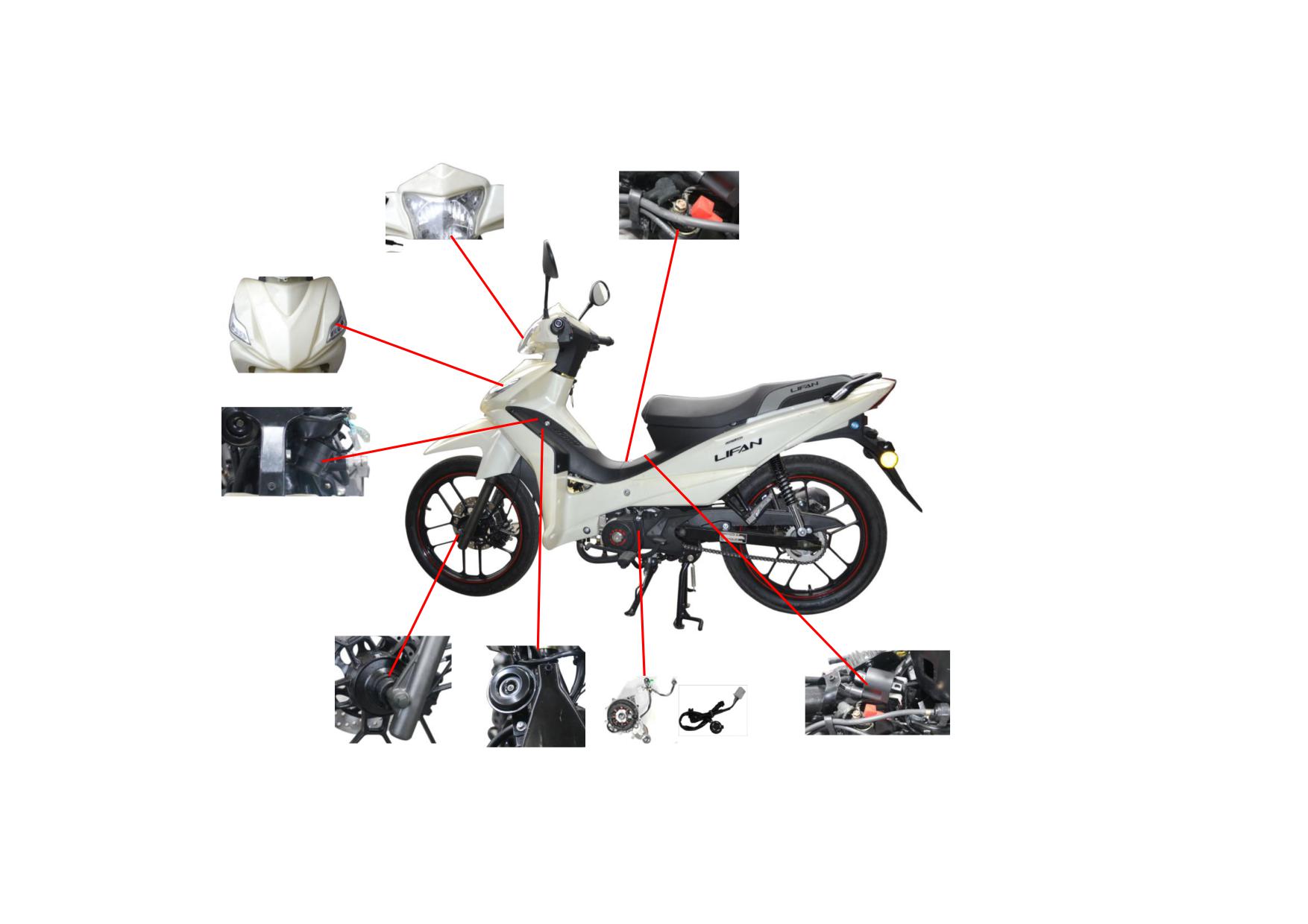
HEADLIGHT
STARTING RELAY
FR. WINKER, LH/RH
FLASHING RELAY
SPEED SENSOR
IGNITION COIL
MAGNETO&GEARSHIFT SW.
4-2
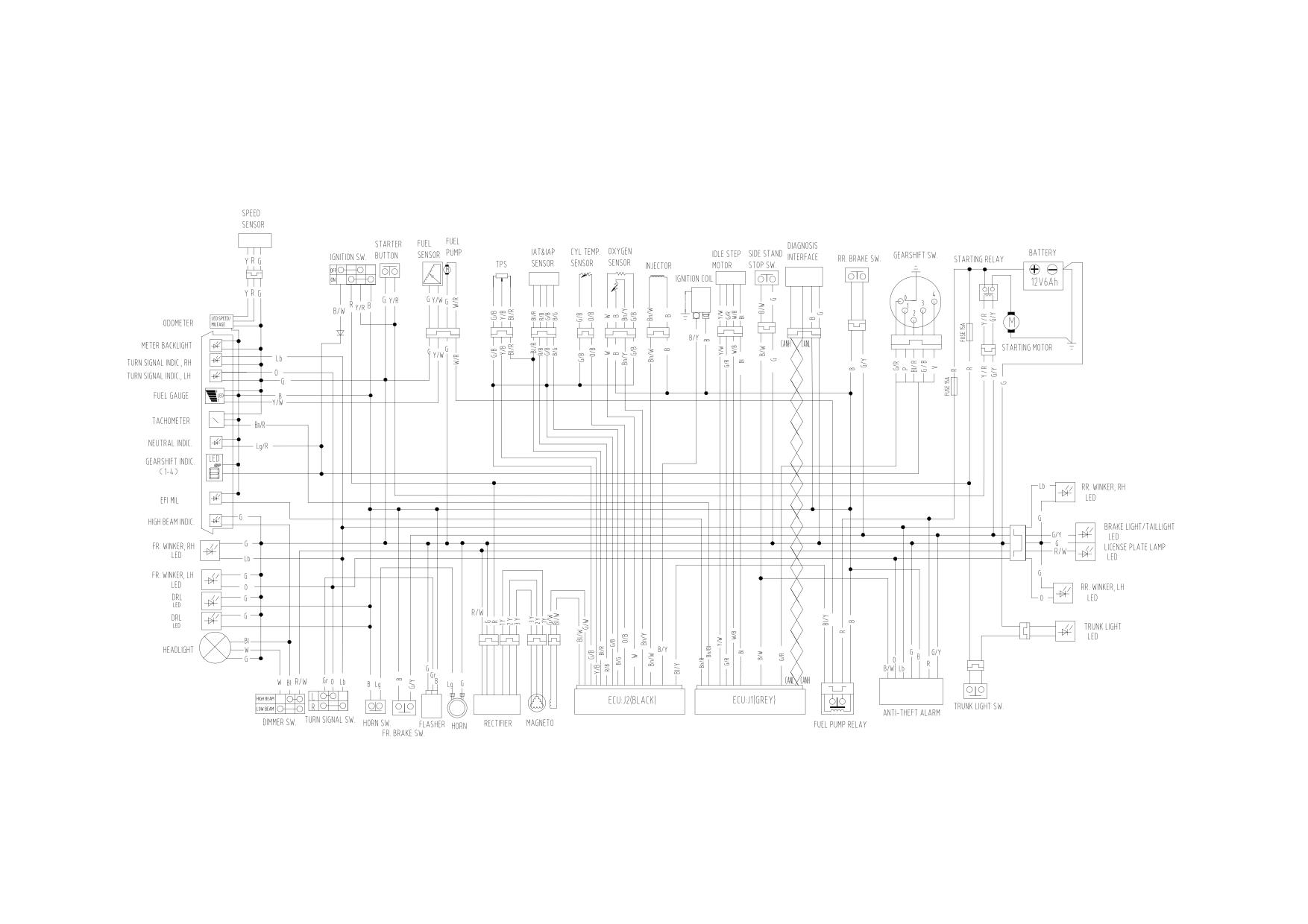
●Electric diagram
4-3
4.1
CHARGING SYSTEM
The vehicle is equipped with a battery 12V and a set of charging system as electric power.
● The charging system consists of:
1)Battery 12V6Ah
2)Magneto (permanent magnet alternator): rotor and stator (including charging/lighting coil and exciter coil)
3)Rectifier: 3-phase full wave
4)Fuse: cartridge fuse 15A with a spare one.
The battery is connected with the generator in parallel, supplying the electric equipment with power together.
● The charging system is designed not only to supply the electrical devices with power when the generator generates sufficient electrical energy, but to charge the
battery. Therefore, a portion of electrical energy is stored to ensure power supply to the electrical devices in case of insufficient power supply caused by low
generator speed or high electrical load.
4.1.1 Removal, Installation and Maintenance of Charging System
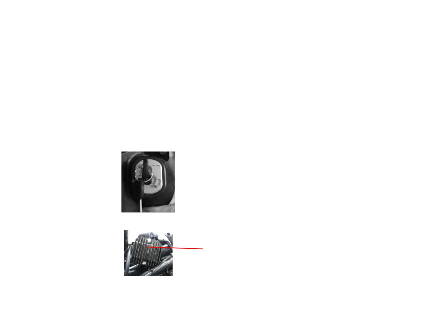
Turn on the ignition switch.
IGNITION SW.
Disconnect coupler of the rectifier to main cable and check it for short circuit, broken circuit or poor connection. Repair or replace it if necessary.
RECTIFIER
4-4
The charging voltage of rectifier should be within 13V~15V. If it's less than 13V, and the malfunction is determined from the rectifier, replace the rectifier with a
new one.
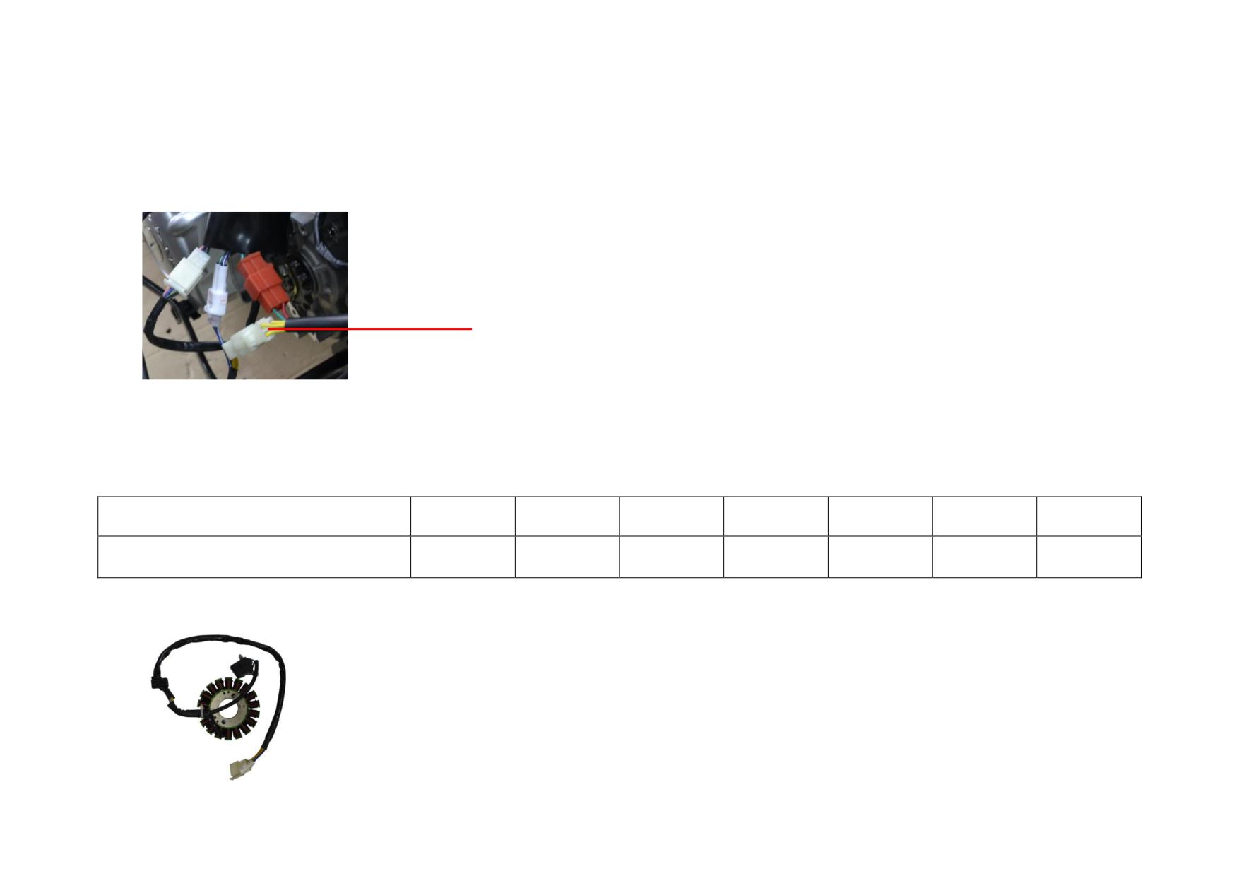
Disconnect coupler of the magneto charging/lighting coil to main cable and check it for short circuit, broken circuit or poor connection. Repair or replace it if
necessary.
COUPLER OF CHARGING/LIGHTING COIL LEAD WIRE (THE YELLOW WIRES
ARE CHARGING/LIGHTING COIL.)
The resistance of charging/lighting coil (at 20℃) should be around 1Ω. Measure the resistance with multimeter, repair or replace the charging/lighting coil if the
value differs considerably from 1Ω.
Check the charging/lighting coil for short circuit, broken circuit or poor connection. Repair or replace it if necessary.
Start the engine, measure the no-load voltage between yellow wires of charging/lighting coil with multimeter (A.C. 200V). The standard value should be as the
following table:
Engine speed (r/min)
2000
3000
4000
5000
6000
7000
8000
No-load voltage of charging/lighting coil (V)
35±1
55±1
70±1
85±1
105±1
120±1
140±1
Replace the magneto stator if the measured no-load voltage differs considerably from the above table.
CHARGING/LIGHTING COIL
4-5
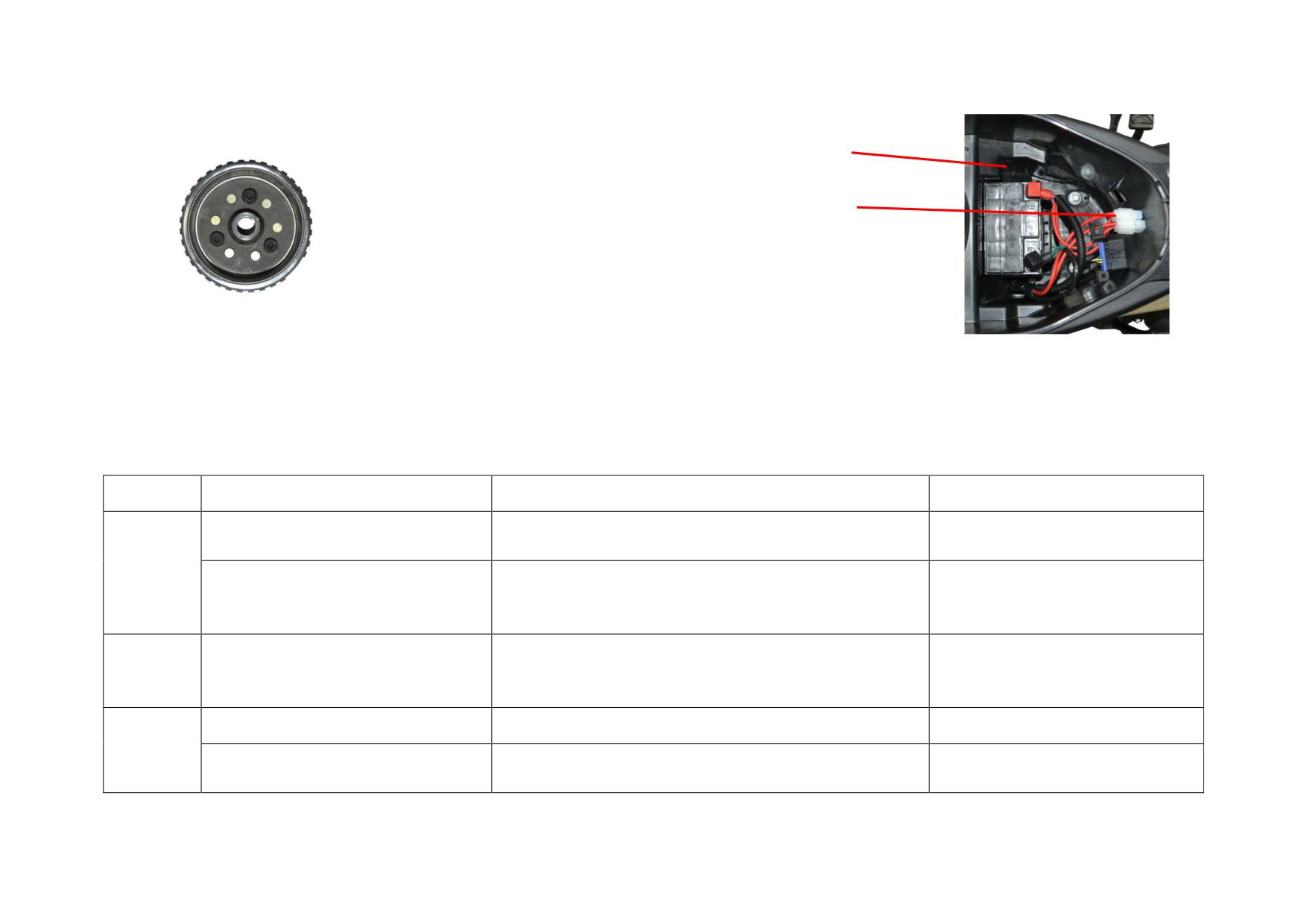
Remove the magneto rotor flywheel and check the rotor for magnetism. Replace it if necessary
BATTERY
FUSE
MAGNETO ROTOR
Check the battery voltage. If it's below 12V, recharge the battery in time.
Check the fuse and replace it with same specification (15A) one if necessary. It's forbidden to take other materials, other ways instead or remove the fuse to connect
with the vehicle circuit, which may cause the vehicle burning.
4.1.2 Troubleshooting to Charging System
Description
Damage Form
Trouble Symptom
Remedy
A short circuit occurs to the
Low voltage output or the battery is not fully charged.
Replace the charging/lighting coil
charging/lighting coil.
Magneto
A broken circuit occurs to the
No voltage output, insufficient battery power or the electric
charging/lighting coil. (the resistance is
Do.
appliances are out of work.
∞).
Short/broken circuit occurs or the battery is not fully charged.
Rectifier
The rectifier is faulty.
Light is dim or out of work. The charging current is too high or
Replace the rectifier.
the battery is deformed.
The battery is damaged.
No power output or the starting motor fails to run.
Replace the battery.
Battery
Shortage of electrolyte due to long-term
Low power/voltage output. The starting motor fails to run or
Charge or replace the battery.
storage.
runs slowly. The signal system is out of work.
4-6
4.2
IGNITION SYSTEM
Ignition: EFI ignition, please refer to Chapter 5.
●The ignition system consists of battery (D.C. 12V), magneto, exciter coil, ECU, ignition coil, spark plug and so on. The function of the ignition system is to supply
a sufficiently high voltage to the spark plug at a certain moment, generating a strong enough electric spark between the two electrodes of the spark plug to ignite the
compressed mixture, thus enabling the engine to work.
Magneto and exciter coil: the magneto rotor flywheel is of single convex plate with outer trigger type. The standard value of exciter coil (at 20℃) should be in
110Ω-130Ω.
Ignition coil: 1) It is a basic component that converts low-voltage electricity output by the igniter into the required high-voltage electricity, which is actually a step-up
autotransformer (withstand voltage≥35KV). 2) Working principle: When the primary current changes, due to electromagnetic induction, the secondary induction
generates tens of thousands of volts of high-voltage electricity. 3) Composition: It consists of an iron core, a primary coil, a secondary coil, a skeleton, high and low
voltage lead wires, a spark plug cap (including a damping resistor, without a metal shield), etc. The primary coil has a thick enameled copper wire with a smaller
number of turns, while the secondary coil has a thin enameled copper wire with a larger number of turns. In order to prevent high-frequency ignition pulses from
interfering with other radio equipment, a damping resistor of about 5kΩ is added to the spark plug cap of the ignition coil (to weaken or eliminate the high-frequency
oscillations generated by the ignition spark).
Spark plug: 1) Function: introduces the high voltage generated by the ignition coil into the combustion chamber of the engine, forming an electric spark in the gap
between the electrodes to ignite the mixed gas. 2) Structure: consists of a steel shell, ceramic insulator, electrodes, sealing gasket and sealing packing, without
damping resistor; 3) For the model of the spark plug and the standard value of the spark plug gap, please refer to the instruction manual of this vehicle.
4.2.1 Removal, Installation and Maintenance of Ignition System
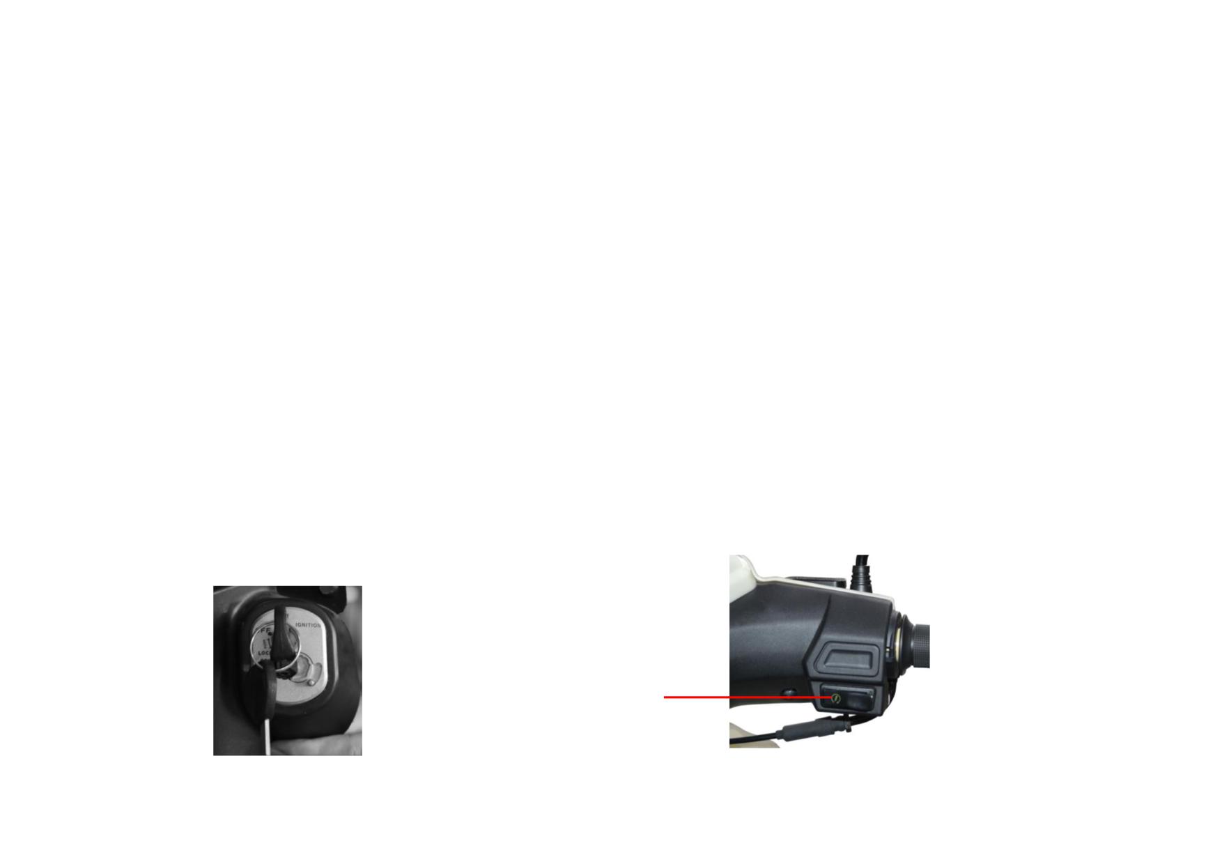
Turn on the ignition switch.
IGNITION SW.
ELECTRIC STARTER BUTTON
4-7
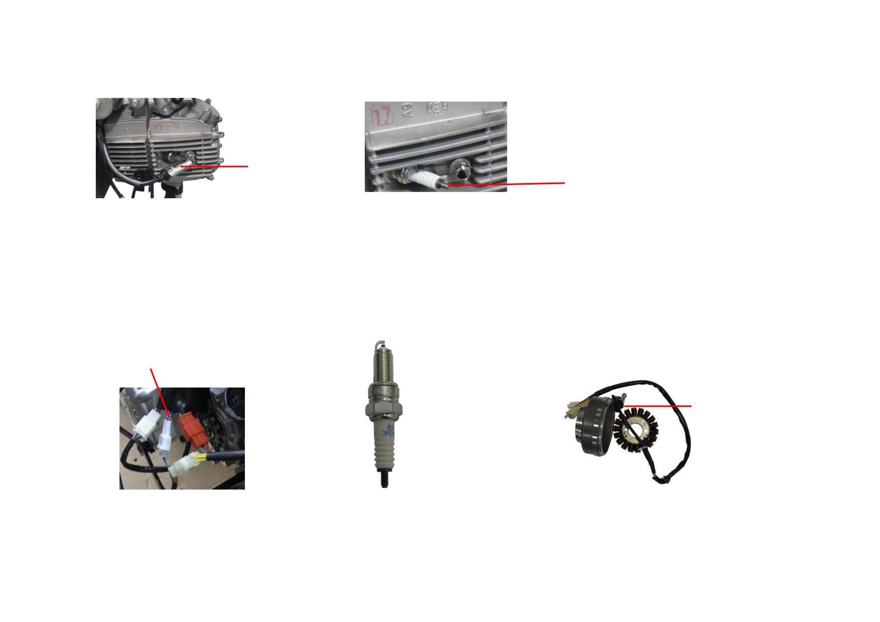
Remove the spark plug cap and replace it if necessary. Spark plug cap resistance: 5kΩ±0.5kΩ
SPARK PLUG CAP
SPARK PLUG METAL POSITIVE HEAD
Remove the spark plug cap on the high-voltage wire of the ignition coil, and clamp the high-voltage wire with an insulating clamp at a position of100mm to 150mm
away from the end of the high-voltage wire at the spark plug cap. It is strictly prohibited to operate with water on your hands to avoid being shocked by high voltage.
Place the end of the high-voltage wire at the spark plug cap close to the metal positive head of the spark plug, keeping the gap at 5mm to 7mm. Step on the starting
pedal or press the electric starting button, and start the engine to conduct a high-voltage misfire test: If the ignition system is normal, a linear blue-white high-voltage
spark will be generated at this gap. If the spark is red or dark red, it indicates that the ignition high voltage is not high enough (normally 10000V to 20000V
high-voltage pulse). The engine cannot be ignited normally, and the ignition system is faulty. It is also possible to remove the spark plug and connect it to the ignition
coil and high-voltage cap to check the strength of the spark between the electrodes of the spark plug.
For the standard value of spark plug gap, please refer to the instruction manual.
COUPLER OF MAGNETO TO MAIN CABLE
EXCITER COIL
SPARK PLUG
MAGNETO
Check the coupler of magneto to main cable, replace it if necessary.
The Blue/White wire and Green wire in magneto lead wire is exciter coil. Measure the resistance of exciter coil, and the standard value should be in 110Ω-130Ω (at
20℃). Further inspection should be done if the measured value differs. The resistor can be damaged by short circuit, broken circuit, or connecting to the metal shell.
4-8
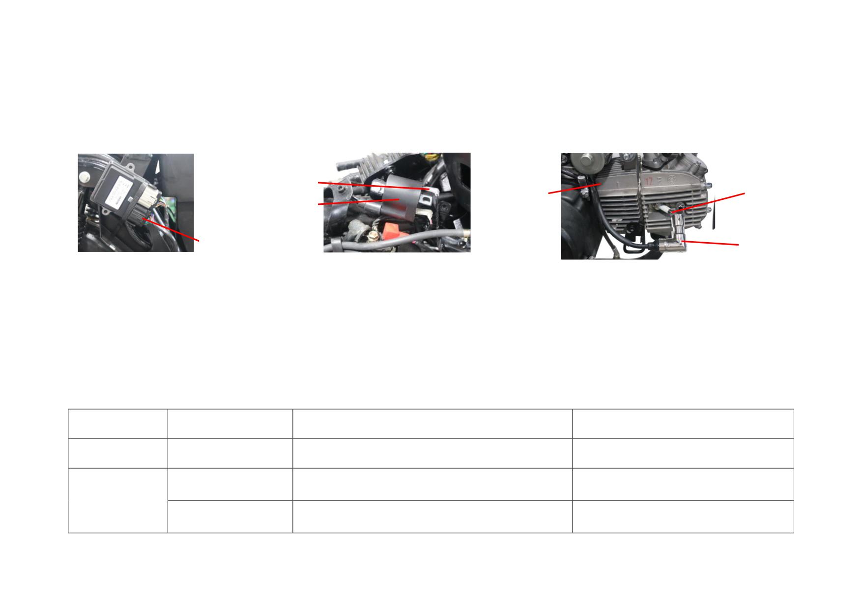
If the exciter coil or insulator is damaged, repair or replace it please.
Disconnect the coupler of igniter to main cable and check it. Repair or replace it if necessary. Check if the black wire has a voltage of D.C. 12V and if the green wire
is well connected with battery (The normal resistance of the wire should be below 0.1Ω).
IGNITION COIL INSERT
OUTPUT HIGH
SPARK PLUG
IGNITION COIL
VOLTAGE CABLE
COUPLER OF ECU TO MAIN
SPARK PLUG CAP
CABLE
Check the ignition coil: The resistance between ignition coil primary insert and iron core is around 0.3-0.8Ω. The resistance between secondary high voltage wire and
iron core is about 4kΩ. The damping resistance of spark plug cap is around 4.5 kΩ-5.5 kΩ. Replace the ignition coil or spark plug cap if necessary.
NOTE: Do not plug or unplug ECU with power on.
It's strictly prohibited to disassemble ECU. Do not pry the pins in socket by hard objects.
Avoid knocking or colliding with hard objects against the ECU. Water/oil penetration into ECU or its connectors are strictly prohibited.
4.2.2 Troubleshooting to Ignition System
Description
Damage Form
Trouble Symptom
Remedy
Ignition power
Broken circuit or poor
No power supply, no/weak ignition spark.
Repair the circuit.
supply
connection
No/weak ignition spark. Engine is hard to start with
Short circuit
Replace the exciter coil.
insufficient power or unstable idle speed.
Exciter coil
Broken circuit (i.e.: the
No ignition spark and the engine fails to start.
Do.
resistance is ∞)
4-9
Ignition
Short circuit
The engine stop switch is out of work.
Replace the faulty switch.
switch/engine stop
switch
Broken circuit
No ignition spark and the engine fails to start.
Do.
ECU
Damaged
Do.
Replace the ECU.
No/weak ignition spark. Engine is hard to start with
Short circuit
Replace the ignition coil
insufficient power or unstable idle speed.
Broken circuit (i.e.: the
Ignition coil
No ignition spark and the engine fails to start.
Do.
resistance is ∞)
Insulator is aged.
Engine is hard to start with insufficient power, unstable idle
Do.
speed or electricity leaks.
Carbon
deposits,
Clean off the carbon deposition, and replace the
electricity leaks or the
spark plug with the same model.
insulator is broken.
Engine is hard to start with insufficient power or unstable idle
Spark plug
Electrodes are worn.
Adjust the spark plug gap or replace spark plug
speed.
with the same model.
Electrodes are burnt.
Replace the spark plug with the same model.
4-10
4.3
SIGNAL SYSTEM AND METER
The signal system consists of turn signal switch, dimmer switch, horn button, horn, LED winker, various LED indicator lamps, flashing relay, front position light,
taillight assy. (braking light, rear position light), front brake switch, rear brake switch, meter and so on.
4.3.1 Removal, Installation and Maintenance of Signal System
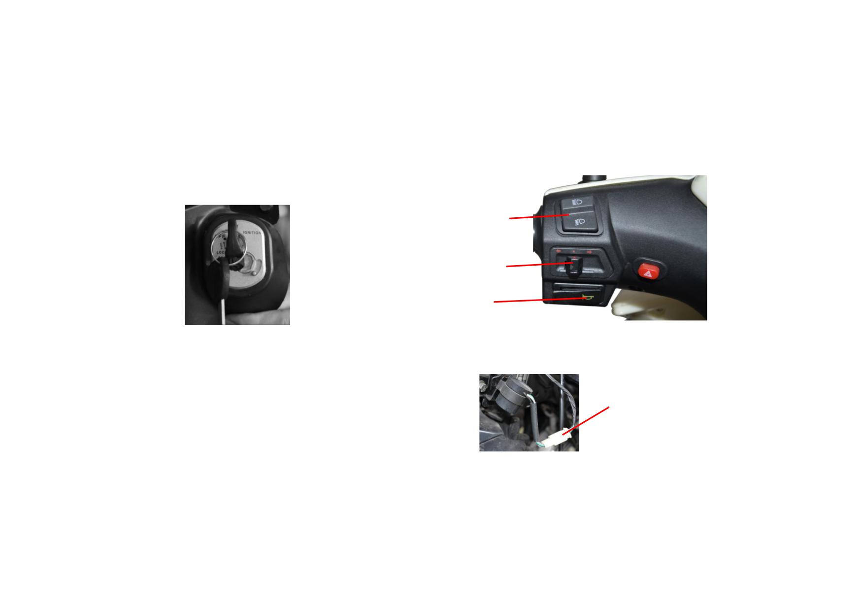
Turn on the ignition switch and check the signal system and meter.
IGNITION SW.
DIMMER SW.
TURN SIGNAL SW.
HORN SW.
Check the battery voltage, fuse and charging system according to the method in charging system, and the voltage should be in normal range.
Disconnect the coupler of flashing relay to meter, and check for short circuit, broken
circuit or poor connection. Repair or replace it if necessary.
Check the LED winker for proper function if the flashing frequency or sound is abnormal.
COUPLER OF FLASHING RELAY TO METER
Replace the winker if necessary.
Check the relative couplers for short circuit, broken circuit or poor connection, and replace
them if necessary.
Check the flashing relay and replace it if necessary.
If the rear position light, braking light, meter backlight & indicator lights, horn, front winker, etc., are out of work, please disassemble the meter case, headlight case
and front cowl. Check the relative couplers for short circuit, broken circuit or poor connection, and replace them if necessary and replace the faulty parts if there
exist.
4-11
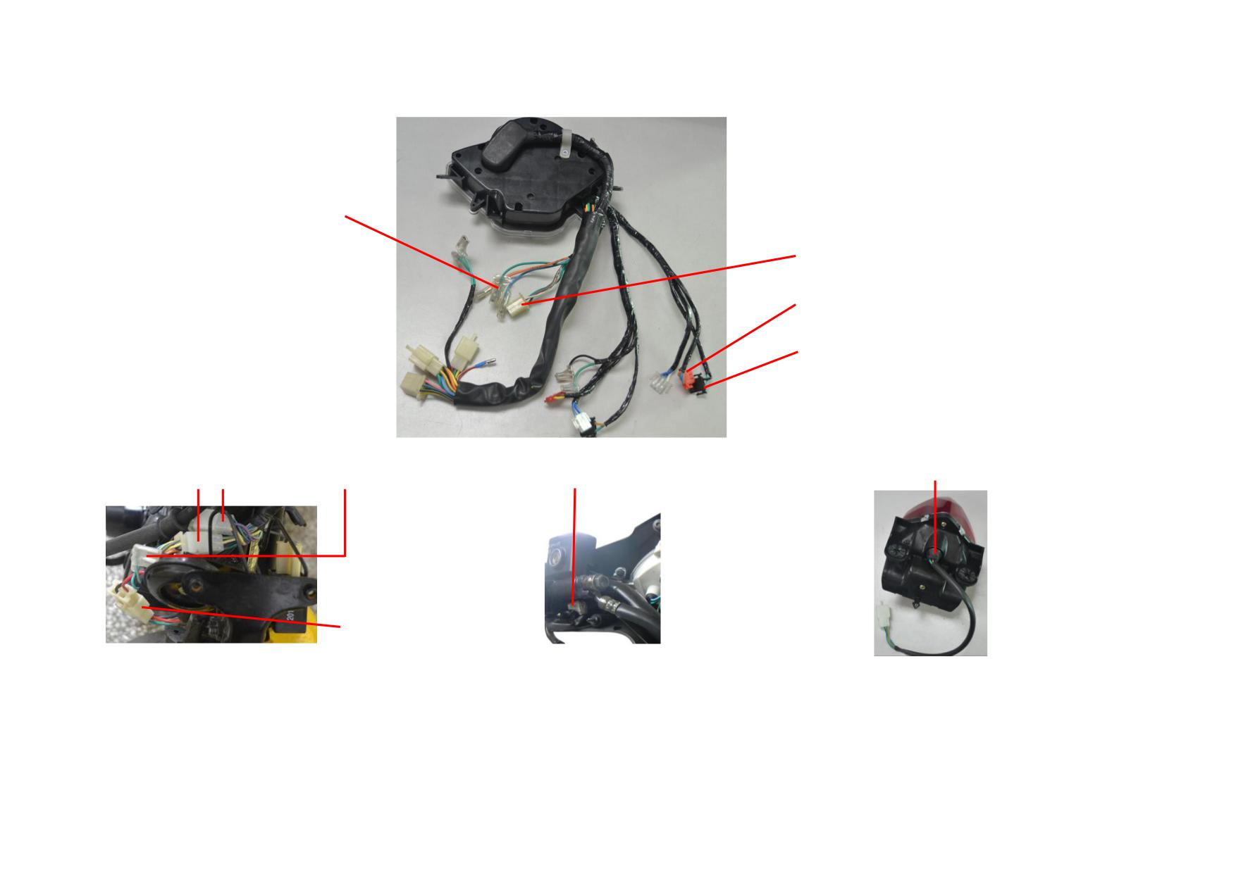
COUPLER OF FRONT WINKER TO METER
COUPLER OF HEADLIGH AND FRONT POSITION LIGHT TO METER
COUPLER OF TURN SIGNAL SWITCH TO METER
COUPLER OF HORN SWITCH TO METER
SOCKET OF BRAKING LIGHT AND REAR POSITION LIGHT
COUPLER OF METER TO MAIN CABLE
COUPLER OF HORN TO METER
FR. BRAKE SWITCH
COUPLER OF IGNITION SWITCH
TO MAIN CABLE
Open the seat and check the bulb of braking light and rear position light. Repair or replace the taillight assy. if necessary.
Check the front & rear brake switches and their couplers to main cable for short circuit, broken circuit or poor connection. Repair or replace them if necessary.
Check the couplers of winker and front position light to main cable for short circuit, broken circuit or poor connection. Repair or replace them if necessary. Check the
relative light sockets for short circuit, broken circuit or poor connection. Repair or replace them if necessary. Check the relative parts and replace them if necessary.
4-12
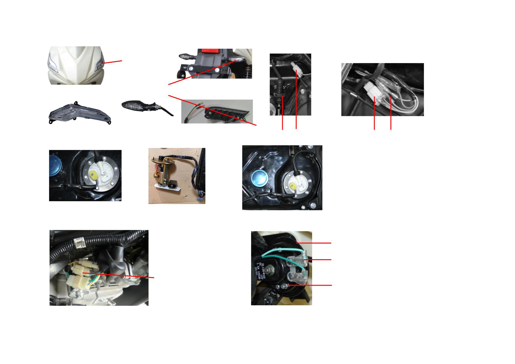
FRONT WINKER
REAR WINKER
COUPLER OF RR. BRAKE SWITCH TO MAIN CABLE
COUPLERS OF BRAKING LIGHT/REAR POSITION LIGHT
AND REAR WINKER
FUEL PUMP & FUEL SENSOR
WIRE HARNESS OF FUEL PUMP & FUEL SENSOR
INSTALLATION PORT OF FUEL PUMP & FUEL SENSOR
HORN
COUPLER OF HORN TO METER
COUPLER OF GEARSHIFT SWITCH
TO MAIN CABLE
ADJUSTING SCREW OF HORN SOUND
4-13
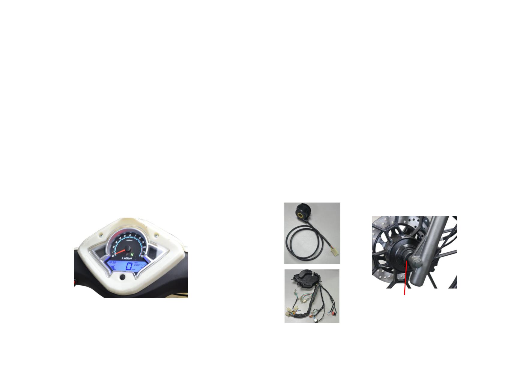
Check the couplers of horn and horn switch to meter for continuity. Repair or replace them if necessary. Turn the horn sound adjusting screw if there is no/weak horn
sound. If the horn is damaged, please replace it with a new one with same specification.
Check such couplers of meter, gearshift switch, fuel sensor, etc. to main cable for continuity. Repair or replace them if necessary. Check the main cable, meter,
gearshift switch, fuel sensor, etc. for proper function as follows: Disconnect the relative couples and check if the gearshift switch, meter indicators circuit, meter
indicator lights, main cable, fuel sensor, etc. are in good condition by connecting them to a D.C. 12V battery with a multimeter. Repair or replace them if necessary. If
the odometer is faulty, please check the speedometer, its cable and its coupler to meter, and repair or replace them if necessary. If the meter is faulty and the external
circuit is in good condition, please check the internal circuit for short circuit, broken circuit or poor connection, and repair or replace them if necessary. Then check
all the parts of meter, repair or replace the meter if necessary.
Disconnect the fuel sensor to main cable, measure the resistance between the two leads of fuel sensor with multimeter. When fuel level is at the highest, the standard
resistance should be within 6Ω-10Ω. When fuel level is at the lowest, the standard resistance should be within 95Ω-101Ω. Please check the fuel sensor leads and
resistance board if the measured values differ considerably from the standard values. And replace them if necessary.
When the gearshift switch is set into a certain gear, the gear line will be connected to the battery negative leads or engine housing. At this time the gearshift indicator
should show the current gear number. When the turn signal switch is set to left/right, or the dimmer switch is set to high beam, the corresponding meter indicators
should show left/right or the high beam indicator should light up. When pressing the horn button, the horn should sound normally. When the lighting switch is set to
position light or headlight, the front and rear position light and headlight should light up at the same time. Check the relative parts and replace them if necessary.
COUPLER OF SPEEDOMETER
TO METER
COUPLER OF SPEED SENSOR
SPEEDOMETER
TO METER
METER
4-14
4.3.2 Troubleshooting to Signal System and Meter
Description
Damage Form
Trouble Symptom
Remedy
Winker
Internal damage
The winker are out of work.
Repair or replace the light.
Front position light
Do.
The front position light is out of work.
Do.
Lighting switch and
Poor connection, broken circuit
The position light or high beam indicator is out of work.
Repair or replace the faulty switch.
dimmer switch
or damage in internal circuit
Turn signal switch
Do.
The winker are out of work.
Do.
Flashing relay
Internal damage
Do.
Replace the flashing relay.
Poor connection or damage in
Front/rear brake switch
The brake light keeps steady on or fails to light up.
Replace the brake switch.
the switch
Rear position light and
Internal damage
The rear position light and brake light fail to light up.
Repair or replace the light.
brake light
Poor connection, broken circuit
Horn button
No/abnormal horn sound.
Repair or replace the horn button.
or damage in internal circuit
Broken circuit or damage in the
Horn
Do.
Replace the horn.
horn
Poor connection when shifting
Gearshift switch
The gear indicator fails to display the current gear number.
Replace the gearshift switch.
gears
Fuel sensor
Internal damage
The fuel gauge fails to indicate correctly.
Replace the fuel sensor.
Internal parts are damaged.
The meter fails to indicate correctly.
Repair or replace.
Do.
The indicators are out of work.
Do.
Meter
Do.
The corresponding lights/meter are out of work.
Do.
Odometer is damaged.
The odometer or tachometer fail to indicate correctly.
Do.
Meter cable
Cable is broken.
The meter backlight and signal system are out of work.
Replace meter cable.
4-15
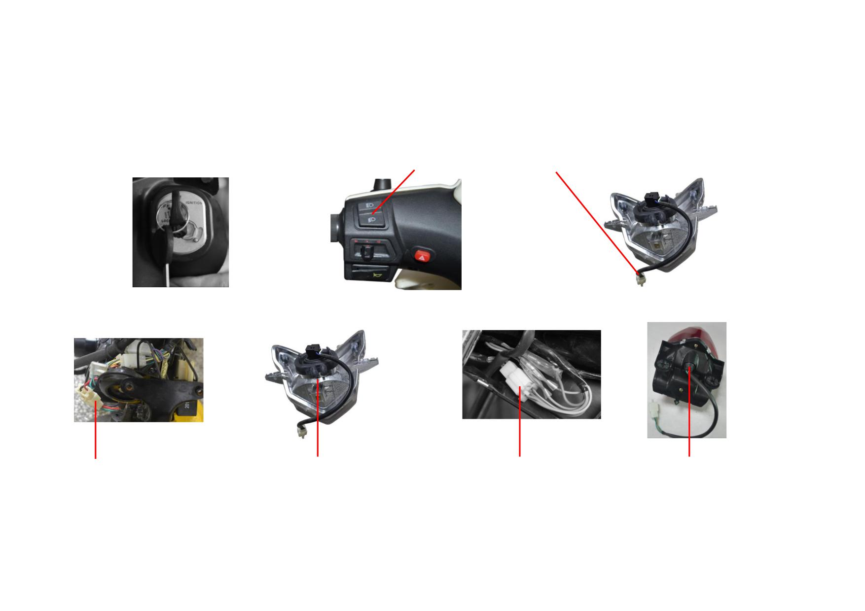
4.4
LIGHTING SYSTEM
The lighting system includes dimmer switch, headlight, LED license light, etc.
4.4.1 Removal, Installation and Maintenance of Lighting System
Turn on the ignition switch, and check the lighting system.
DIMMER SWITCH
COUPLER OF HEADLIGHT TO METER
IGNITION SW.
Check the battery voltage, fuse and charging system according to the method in charging system, and the voltage should be in normal range.
COUPLER OF IGNITION SW. TO
BULB AND SOCKET OF
COUPLER OF LICENSE PLATE LIGHT
SOCKET AND COUPLER OF
MAIN CABLE
HEADLIGHT
TO MAIN CABLE
LICENSE PLATE LIGHT
If the headlight fails to work, open the meter housing and headlight housing, check the relative couplers for continuity and check the relative parts for damage. Repair
or replace them if necessary. Check ignition switch, coupler of license plate light to main cable, couplers of headlight, dimmer switch, etc. to meter for continuity.
Repair or replace them if necessary. Disassemble the headlight and license plate lamp if necessary, check the circuit element and light socket, repair or replace them if
4-16
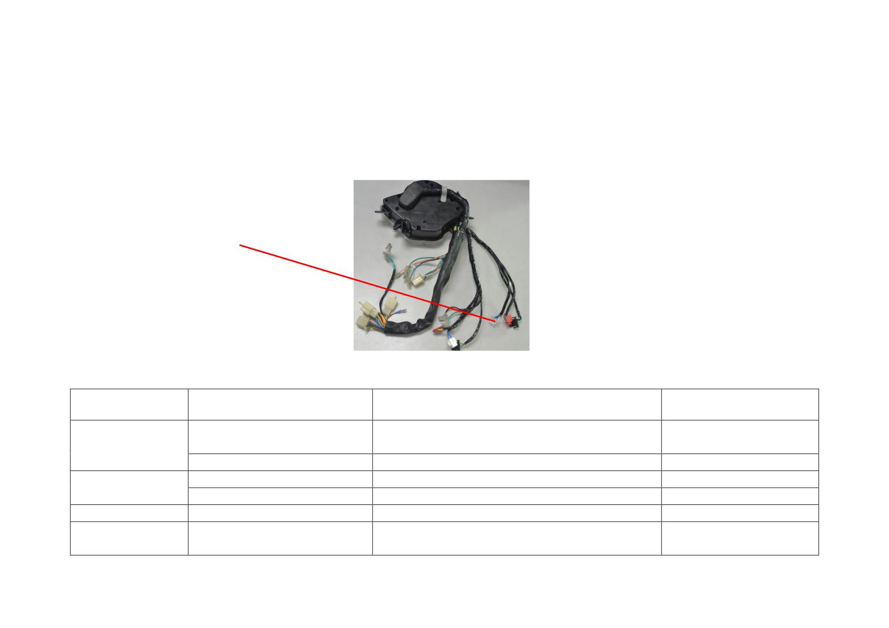
necessary. Check the main cable and the internal of ignition switch for continuity, and repair or replace them if necessary.
To test the fault: Please disconnect the relative coupler according to the electric diagram, and connect it to a D.C. 12V battery with a multimeter. Then judge if the
part is faulty or not.
When the vehicle is started, the headlight will light up: If the dimmer switch is set to low beam at this time, the headlight will provide low beam lighting. If the
dimmer switch is set to high beam at this time, the headlight will provide high beam lighting.
When the ignition switch is turned on, the license plate light will light up.
COUPLER OF DIMMER SW. TO METER
4.4.2 Troubleshooting to Lighting System
Description
Damage Form
Trouble Symptom
Remedy
Magneto
Low output voltage, low brightness, or insufficient battery
Short circuit
Replace the coil.
charging/lighting
charging
coil
Broken circuit
No output voltage, low brightness, or battery fails to charge.
Do.
The headlight is improperly installed.
The lighting beam is improper.
Adjust the headlight.
Headlight
The filament is burnt.
The headlight fails to work.
Replace the bulb.
License plate light
Internal damage
The license plate light fails to work.
Repair or replace.
Poor connection, broken circuit or
Dimmer switch
The headlight or license light fails to work.
Repair or replace the switch.
damage in internal circuit
4-17
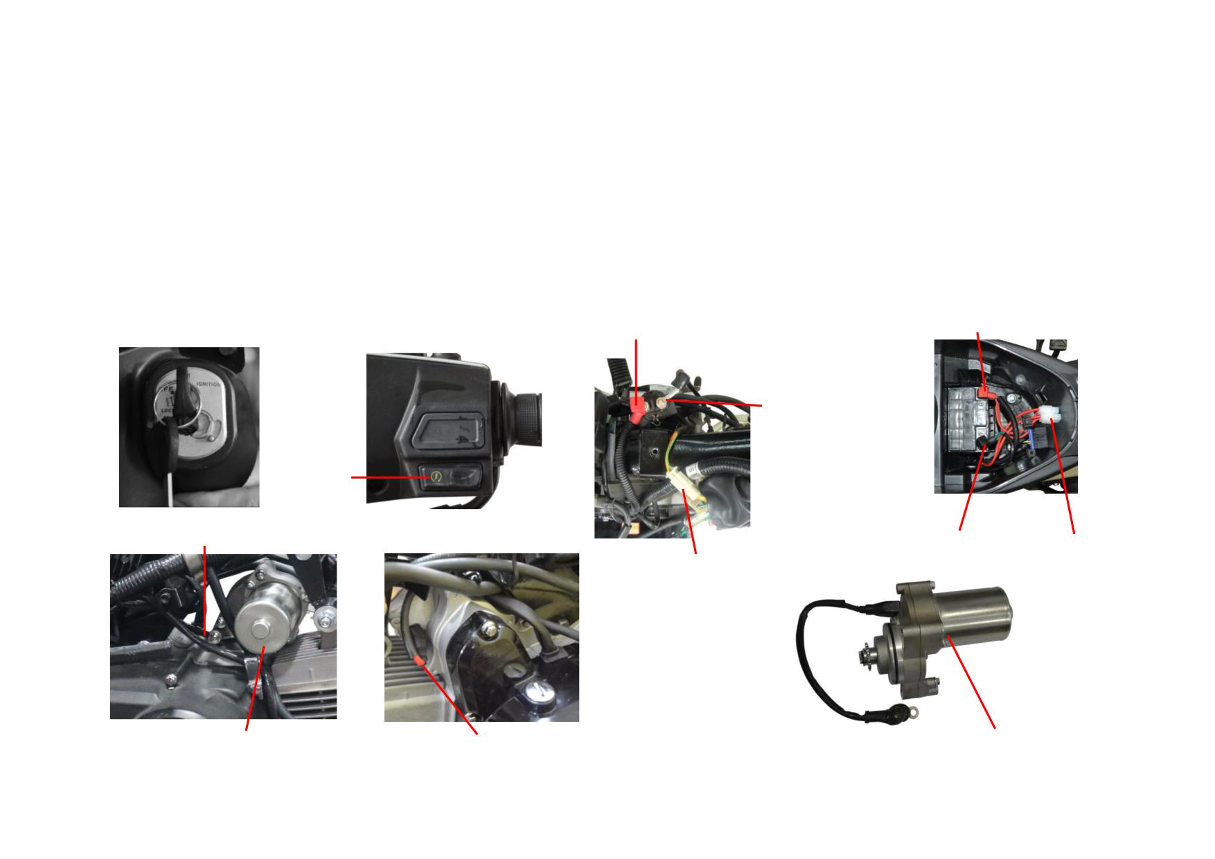
4.5
ELECTRIC STARTING SYSTEM
Electric starting mode: brake starting.
The electric starting system includes starting motor, starting relay, ignition switch, electric starter button, grounded cable, front/rear brake switch, battery, fuse etc.
In order to start the engine, a DC 12V power supply and a reliable ignition system are necessary. The following is a special introduction to the removal, installation
and maintenance of the electric starting system. For the removal, installation and maintenance of the charging system and ignition system, please refer to the previous
chapters.
4.5.1 Removal, Installation and Maintenance of Electric Starting System
Turn on the ignition switch and check the electric starting system.
COUPLER OF BATTERT POSITIVE LEAD TO MAIN CABLE
COUPLER OF STARTING RELAY TO MAIN CABLE
IGNITION SW.
COUPLER OF STARTING
MOTOR POSITIVE LEAD
TO STARTING RELAY
ELECTRIC
STARER
BUTTON
COUPLER OF GROUNDED WIRE OF MAIN
CABLE TO ENGINE HOUSING
COUPLER OF BATTERT NEGATIVE
FUSE
COUPLER OF STARTING RELAY COIL TO
LEAD TO MAIN CABLE
MAIN CABLE
STARTING MOTOR
COUPLER OF STARTING MOTOR POSITIVE LEAD WIRE
STARTING MOTOR POSITIVE LEAD WIRE
STARTING MOTOR
4-18
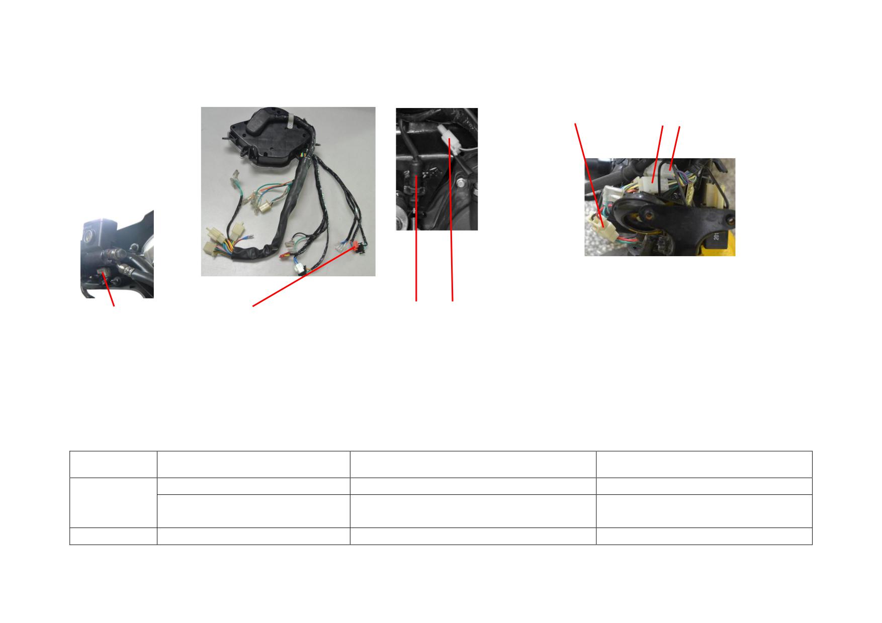
COUPLER OF IGNITION SW. TO MAIN CABLE
COUPLER OF MAIN CABLE TO METER
FR. BRAKE SW
COUPLER OF ELECTRIC STARTER BUTTON TO METER
RR. BRAKE SW. AND ITS COUPLER TO MAIN CABLE
If the vehicle fails to electric starting, please check the couplers of electric starter button, front brake switch, etc. to meter, coupler of starting motor positive lead,
coupler of meter to main cable and coupler of starting motor positive lead to starting relay, and check the couplers of ignition switch, rear brake switch, starting relay,
battery, fuse, engine housing to main cable for continuity. Repair or replace them if necessary. Check the relative parts for internal damage, short circuit, broken
circuit or poor connection, and repair or replace them if necessary.
4.5.2 Troubleshooting of Electric Starting System
Description
Damage Form
Trouble Symptom
Remedy
Short circuit or broken circuit in the coil.
The starting motor and vehicle fails to start.
Replace the relay.
Starting relay
The starting motor runs abnormally and the vehicle
Internal damage
Do.
fails to start.
All switches
Internal damage or poor connection
The starting motor and vehicle fails to start.
Replace the fault switches.
4-19
The electric starting system has no power, and the
Replace the fuse with the same specification
Fuse
Poor connection or the fuse is burnt.
vehicle fails to start.
one.
The starting motor fails to run or runs abnormally
Battery
No voltage or voltage is too low
Repair or replace the battery.
and the vehicle fails to start.
4-20
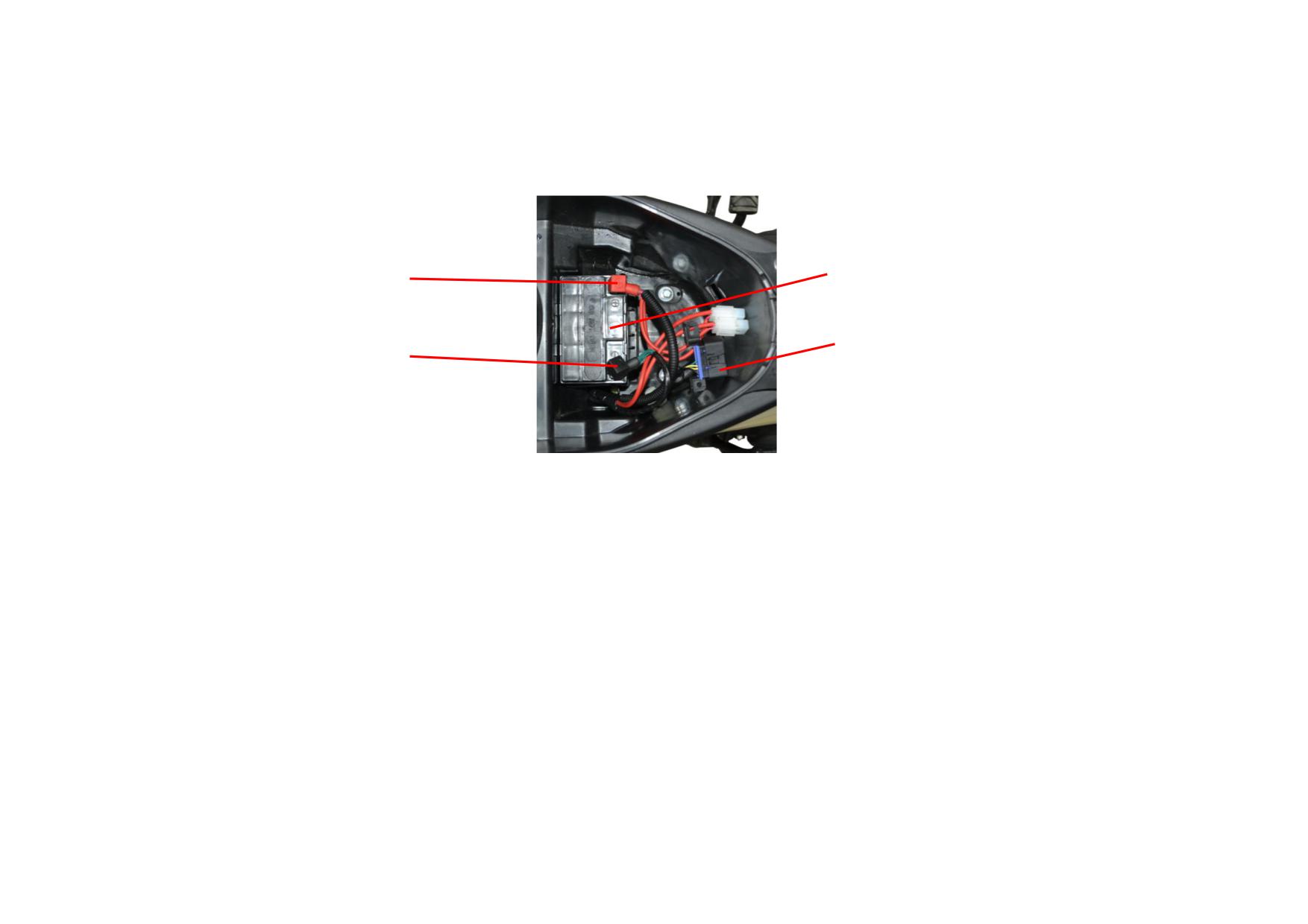
4.6
BATTERY AND FUSE
CONNECTING WIRE BETWEEN MAIN CABLE
BATTERY
TO BATTERY POSITIVE ELECTRODE
FUSE
CONNECTING WIRE BETWEEN MAIN CABLE
TO BATTERY NEGATIVE ELECTRODE
Measure the battery voltage. If it's below 12V, charge the battery in time.
Fuse: 15A, with a spare one. Check the fuse and replace it with same specification (15A) one if necessary. It's forbidden to take other materials, other ways instead or
remove the fuse to connect with the vehicle circuit, which may cause the vehicle burning.
4.6.1 Battery Maintenance
(1) Battery 12V6Ah (model:MTX7L-BS): is of maintenance-free type. The electrolyte is filled in the sealing shell by the manufacturer before leaving the factory,
which fundamentally eliminates the acid leakage in common lead-acid batteries and the inconvenience of frequent filling of electrolyte or distilled water, so there’s
no need to check or replenish the battery electrolyte. However it's important to note that the sealed electrolyte cap should never be removed. If the vehicle is not used
for a long time, remove the battery, charge it, and store it in a cool, ventilated place.
Adding electrolyte: Electrolyte should be added to the unused battery first. After adding the electrolyte to battery, reinstall the battery plug in place to avoid
electrolyte leakage. Warning: The main component of electrolyte is sulfuric acid which is corrosive, so reliable protective measures must be taken if it comes into
contact with skin or eyes, which will cause severe burns.
Charging method: The battery can reach 75% of rated capacity after adding electrolyte and placing for 20 minutes and can be used without charging in this case.
When conditions permit, it's better to use the battery after additional charge. Generally it takes 3 hours to charge with 1A current, but it is best to charge with 0.6A
current for 6 to 8 hours.
4-21
If the vehicle is not used for a long time, the battery will discharge itself and cause insufficient capacity. Please remove the battery, charge it, store it in a cool,
ventilated place, and charge the battery every 3 months. After 2 to 3 years of normal use, the battery capacity will also decrease, and it must be recharged to restore
the voltage.
(2) Clean the battery terminals: Turn off the ignition switch, open the seat, and disconnect the negative and positive leads from battery. Clean the battery terminals
with wire brush as shown in the figure. After cleaning, coat the terminals with a thin layer of grease, and connect the battery cables in reverse order of removal.
Attention: If the battery is to be removed, disconnect the negative lead first, then the positive lead. Connection should be done in reverse order of removal.
4.6.2 Replacement of Fuse
(1) Before checking and replacing the fuse, turn off the ignition switch so as to prevent an accidental short circuit.
(2) Open the seat, barrel cover and battery protective cover, and the fuse is located in the fuse box near the battery.
(3) Open the fuse box, and check if the fuse is burnt. If the fuse burns frequently, it usually indicates an overloaded circuit or a short circuit. The fault should be found
out and eliminated before normal use.
(4) Replace the fuse as follows: Open the fuse box cover, lift the metal clips at both ends of fuse and the fuse, push the metal clip from the fuse end. Then install the
new fuse into the clips and put on the cover.
(5) Replace the fuse with a new one with the same specification (15A).
WARNING:It's strictly forbidden to take other materials, other ways instead or remove the fuse to connect with the vehicle circuit, which may cause the
vehicle burning.
(6) Reinstall the parts in the reverse order of removal and check if all wire clamps are securely installed.
4-22
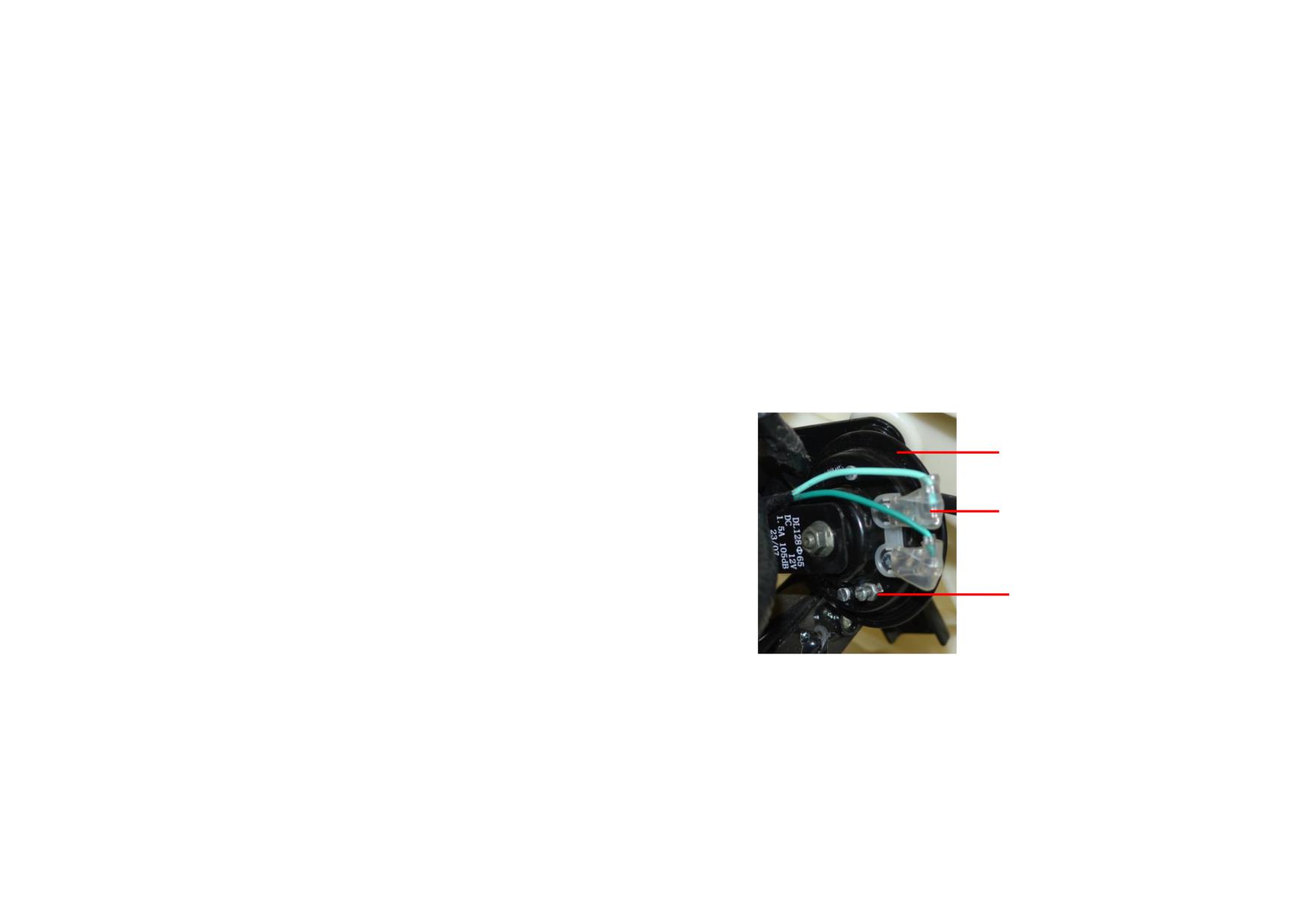
4.7
LIGHTS AND HORN
4.7.1 Lights
For removal, installation and maintenance of lights, please refer to 4.3 Signal system and meter & 4.4 Lighting system.
1) Adjustment of brake light switch
Check the front and rear brake switch for proper function. Turn on the ignition switch, and hold the front brake handle or step on the rear brake pedal, the brake light
will be on. Release the front brake handle or rear brake pedal, the brake light will be off. Adjust the rear brake switch as follows if necessary: Unscrew the locknut,
and tighten the adjusting nut. Then tighten the locknut after adjustment.
2) Winker
Turn on the ignition switch, and operate the turn signal switch to check the front left/right or rear left/right winker for proper function.
3) Headlight, front position light, rear position light
Turn on the ignition switch, and operate the dimmer switch to check the headlight, front or rear position light for proper function.
4.7.2 Horn
1) Function
HORN
Turn on the ignition switch, and press the horn button to check if the horn works normally.
2) Fault
Please refer to 4.3 Signal system and meter for the inspection and maintenance of horn.
COUPLER OF HORN TO METER
Check the horn button for short circuit, broken circuit and poor connection, and repair or replace
it if necessary. If the horn fails to sound or sound weakly, turn the adjusting screw of horn sound.
If the horn is determined to be broken, replace it with a new one with same specification.
ADJUSTING SCREW OF HORN
No horn sound is one of the common troubles, which can be divided into two types, one is the
SOUND
electric circuit fault, and the other is an internal fault.
(1) Check electric circuit fault
When the horn fails to sound, first check the fuse for proper function, then check the horn power supply line. If they're in good condition, it indicates that an internal
fault occurs to the horn.
(2) Internal fault
Nowadays, as the technology of various production manufacturers is improving, the internal faults of the horns are becoming relatively less and less. For some of
them, the frequency of use can even reach more than 100,000 times without faults. However, there still exists some common faults such as erosion appearing on the
connectors, damage to coil, diaphragm broken and so on, among which, erosion appearing on connectors is the most common fault. There is often a process of
4-23
development for erosion appearing on connectors. For example, the horn sounds late after pushing the button, does not sound, the sound is not crisp, the sound is
intermittent and the horn does not sound until the button is pressed again, all of them can be considered as the faults of horn connectors fault.
4-24
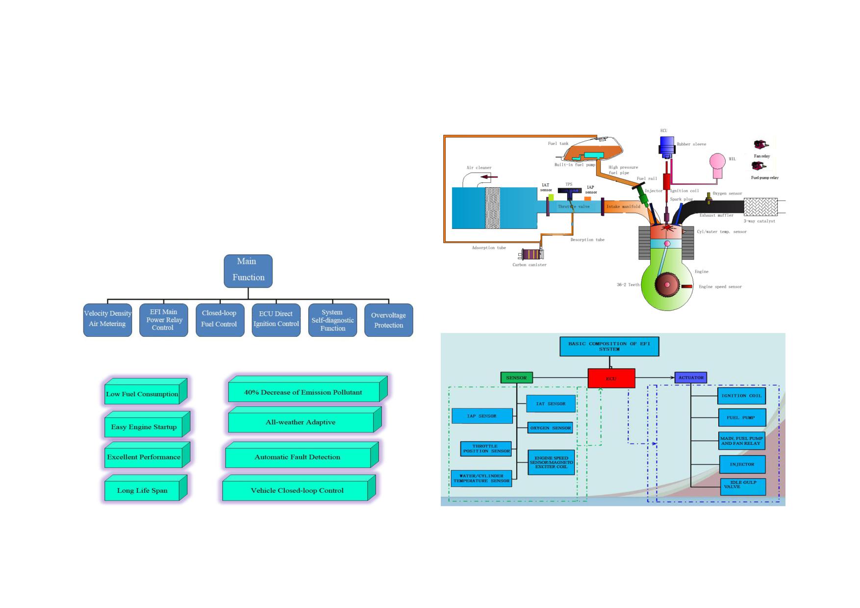
CHAPTER 5 STRUCTURE AND MAINTENANCE OF EFI SYSTEM
5.1 INTRODUCTION OF EFI SYSTEM
5.1.1 Definition
5.1.3 Working Principle of EFI System
By various sensors, the EFI system converts the engine intake air volume,
coolant temperature, engine speed, acceleration, deceleration and other
operating conditions into electric signals, which are then input to the ECU.
Comparing such information with the stored information, the ECU calculates
and outputs the control signal. ECU can not only control the fuel supply
accurately instead of a traditional carburetor, but also greatly improve the
engine performance by controlling the ignition advance angle and idle speed air
flow etc.
5.1.4 Composition of EFI System
5.1.2 Advantages of EFI Motorcycle
5-1
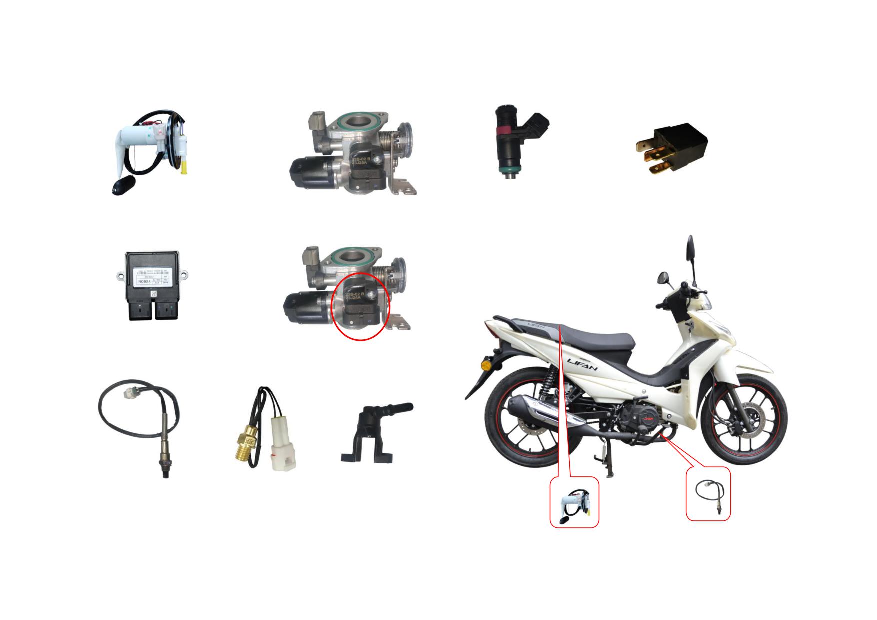
5.2 CONFIGURATION AND LAYOUT OF EFI PARTS
5.2.1 EFI Parts
INJECTOR
RELAY
FUEL PUMP
THROTTLE VALVE BODY
5.2.2 Layout of EFI Parts
ECU
IAP&IAT SENSOR
CYLINDER
OXYGEN SENSOR
TEMPERATURE
OIL RAIL
SENSOR
5-2
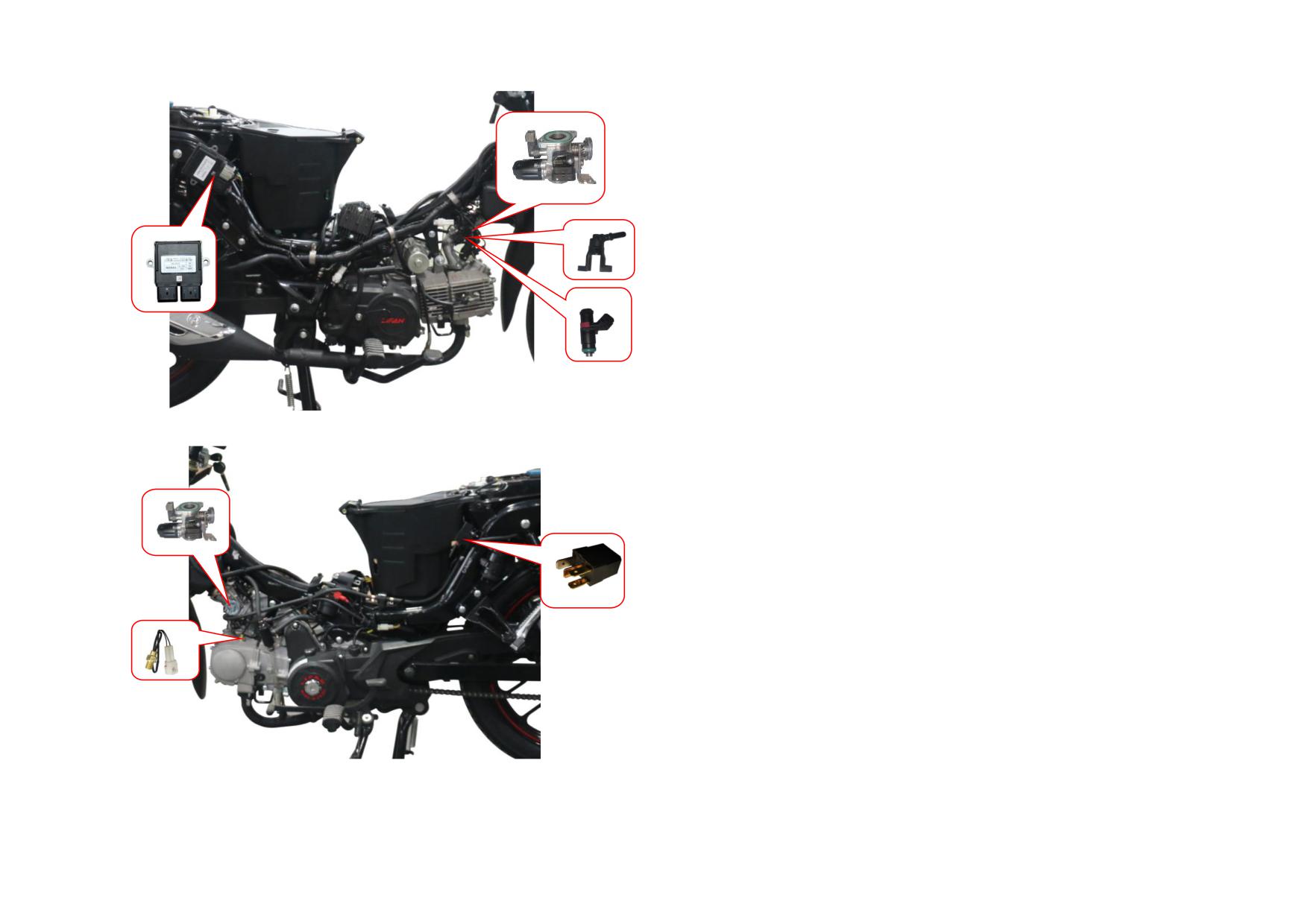
5.3 EFI PERFORMANCE AND MALFUNCTION
5.3.1 ECU
Function
ECU is a kind of electronic control integrated device. The optimal fuel injection
timing of the engine under various working conditions is stored in the ECU
memory. After receiving signals from various sensors, the fuel injection quantity
satisfied the engine running state is determined, and the injection time is
controlled according to the calculated results. ECU can process various
information to realize ignition control, start control and idle speed control etc. In
addition, ECU can connect with the instrument to provide RPM and temperature
signal, with the diagnostic scanner for malfunction diagnosis, with the ECU
anti-theft device to realize the anti-theft control.
Installation Location
ECU can be installed in any place, but it must be far away from the high
pressure transformer to prevent interference.
5-3
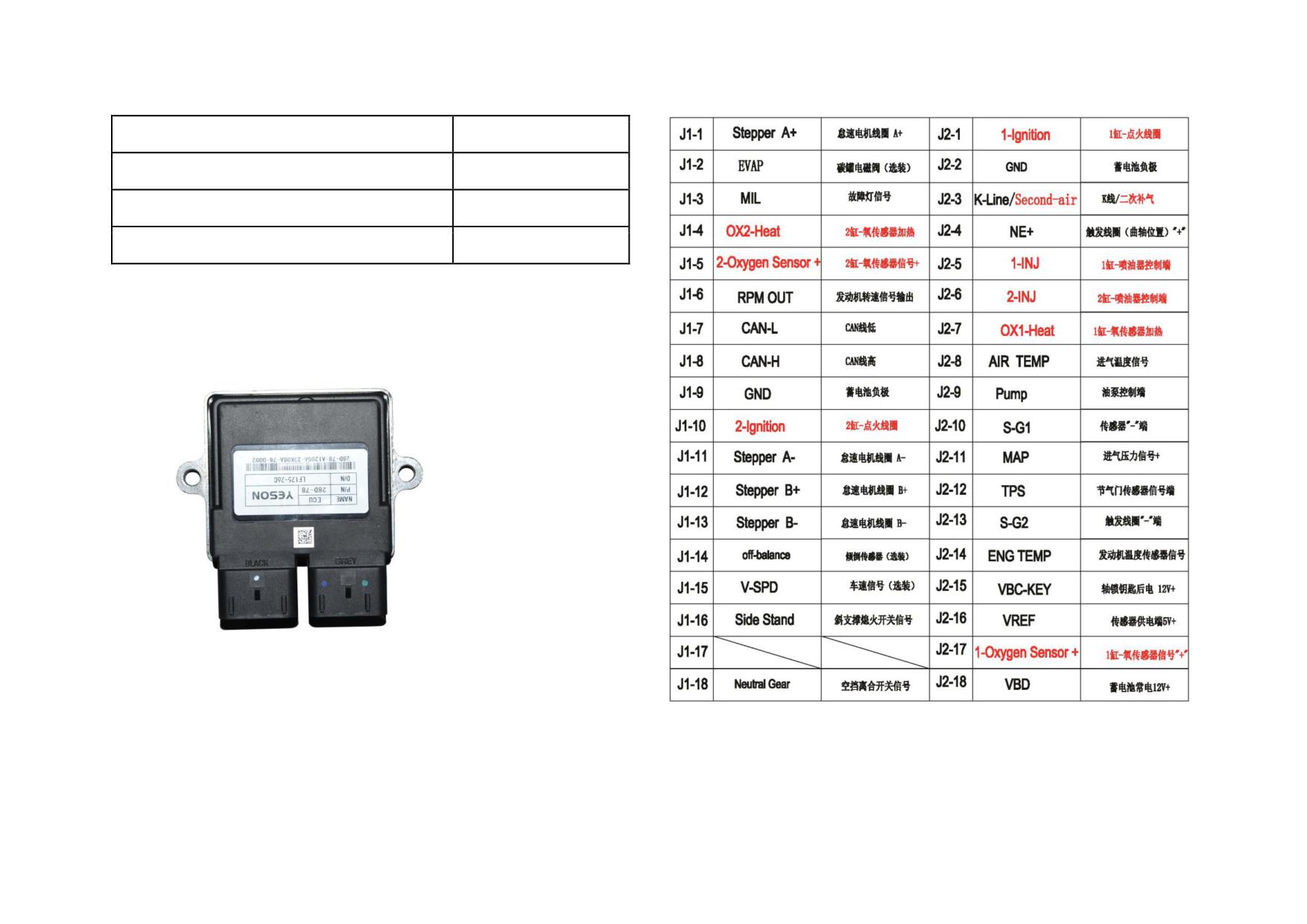
ECU Parameters
Definition of ECU Pin
Item
Value
Battery voltage range in normal (V)
9~15
Working temperature (℃)
-30~80
Storing temperature (℃)
-40~90
Malfunction Mode
Invalid connector, damaged elements, short-circuit due to water entering, loose
and invalid elements due to vibration.
NOTE: The pin number is marked according to the digital sequence on back of
the ECU plug at the end of main cable.
5-4
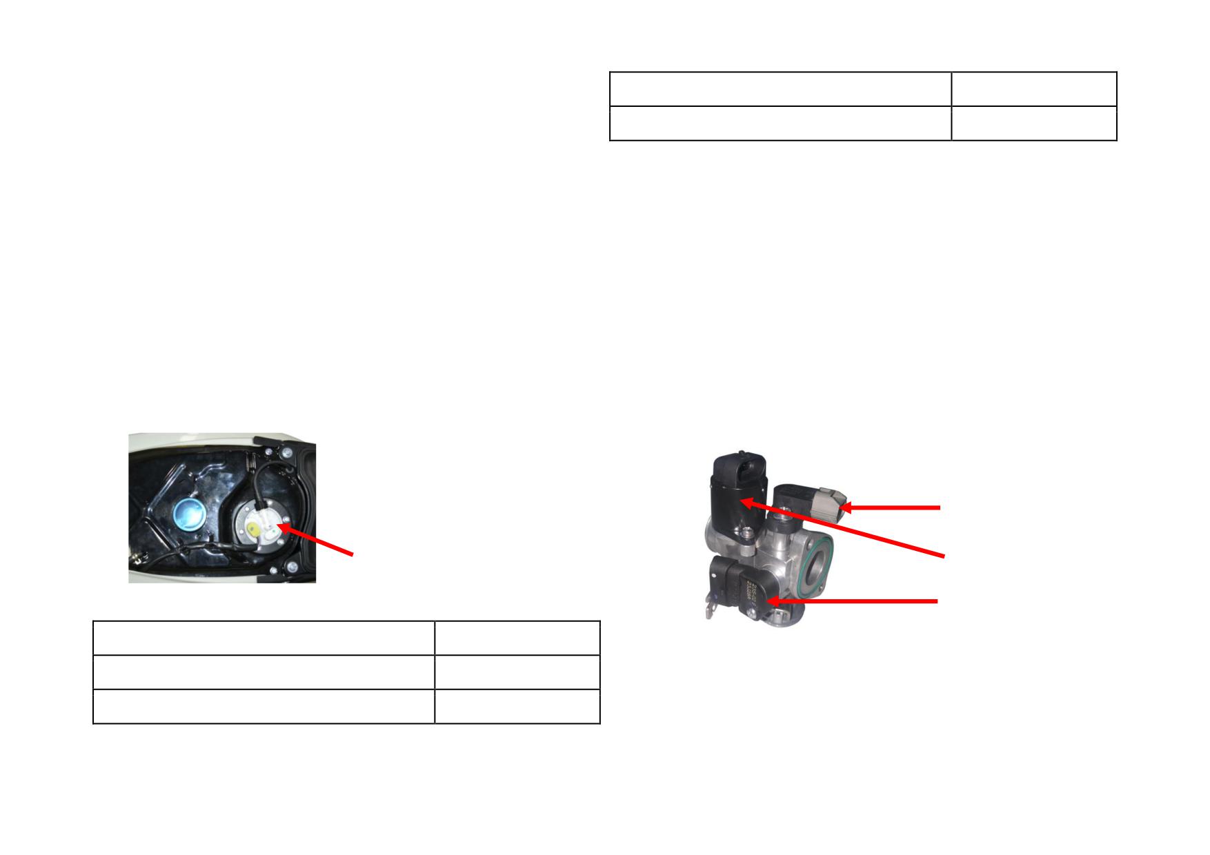
5.3.2 Fuel Pump
Ambient temperature (℃)
-40~80
Function
Allowable fuel working temperature (℃)
-30~70
Fuel pump is used to deliver fuels from fuel tank to engine at certain pressure
and flow rate (as per the different vehicle and engine type).Working condition
Malfunction Mode
of fuel pump: when start the ignition switch, the fuel pump will run for 3s, if
Blocked precise filter, fuel pump fails to rotate, invalid oil pressure regulator,
ECU fails to detect the effective speed signal, the fuel pump will stop; when the
invalid bracket vibration, invalid seal ring.
engine starts to work, the fuel pump will run unless the ECU detects at least 2
5.3.3 Throttle Valve Body Assembly
effective speed signals of missing teeth. Without speed signal, the fuel pump
Function
will stop.
It is installed in the EFI device to monitor opening angle of throttle valve, and
NOTE: For long-term parking (more than 30 days), especially in summer, be
output voltage signal to electronic controller as the load signal of engine and so
sure to drain off fuel to avoid fuel deterioration and gel matter to damage the
as to judge the working condition of engine.
fuel pump.
Installation Location
Installation Location
The throttle position sensor (TPS) is installed on the throttle valve body and
Generally, the bottom installed built-in fuel pump is installed in the bottom of
fixed with a M5 screw after the initial value is adjusted. The throttle valve shaft
the fuel tank. However, the top installed type is installed in the top. It is
can rotate flexibly and has a output voltage 0.58-4.8V after the sensor is
necessary to ensure that the mounting surface is smooth without oil leakage.
power-on. Initial factory setting for output voltage is 0.58-0.65V.
TPS
FUEL PUMP
STEPPER MOTOR
IAT SENSOR
Fuel Pump Parameters
IAP SENSOR
Item
Reference Value
Working voltage (V)
8~15
Fuel system pressure (KPa)
300
5-5
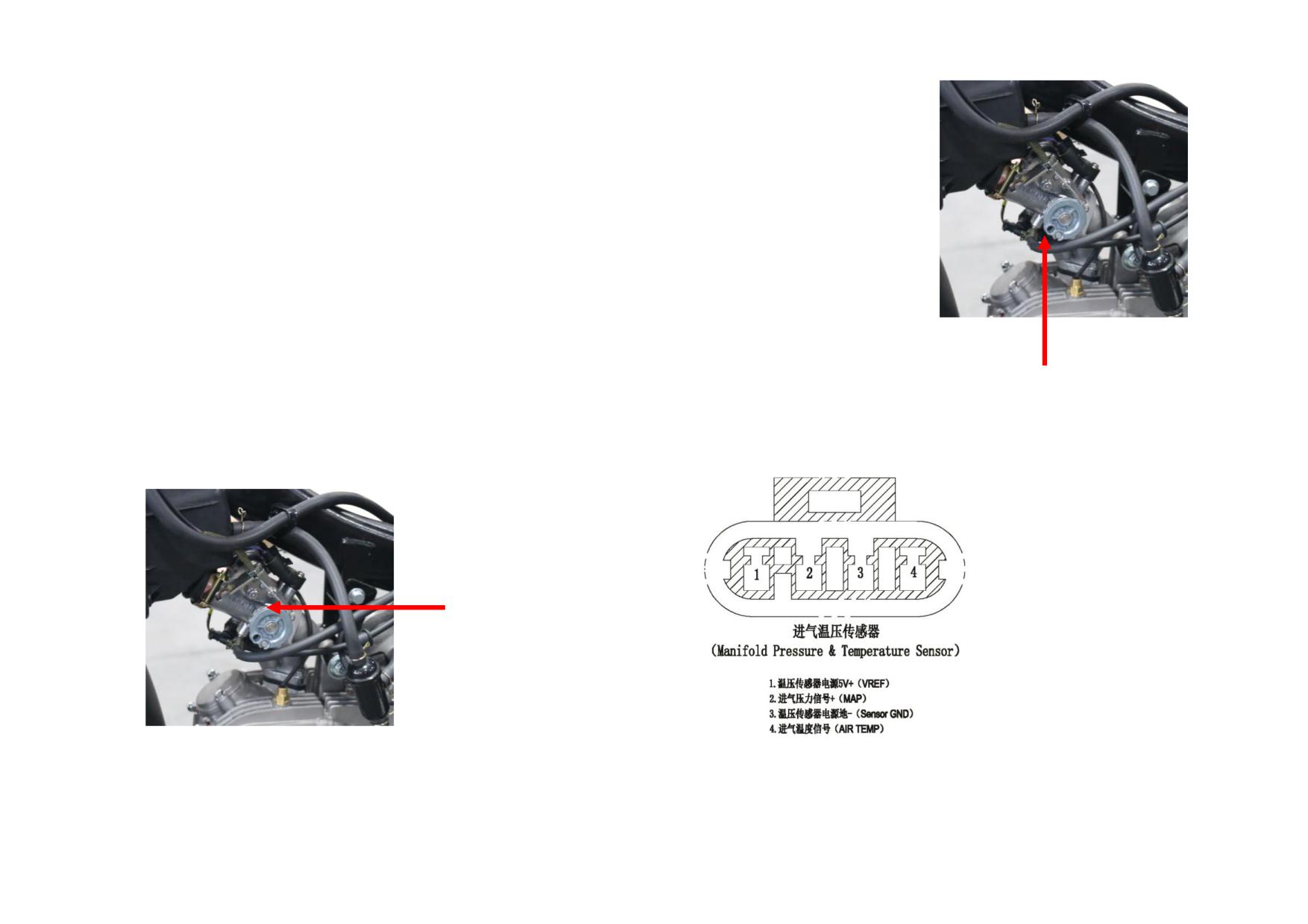
Idle Speed Adjustment
5.3.4 IAP Sensor
(1) Target values of adjustment parameter
Function
RPM: 1300±100r/min (1600±100 r/min for scooter)
It is used to monitor the intake
Ignition advance angle: -0.2-(+6.0) °
manifold absolute pressure and
Cylinder head temp.: 90±3℃
provide engine load information.
TEV opening:30°
Installation Location
Throttle valve position turning angle:0°
It is located on the intake manifold
(2) Adjustment method
or connects with it through a rubber
To increase the TEV opening, clockwise adjust the by-pass bolt; to decrease the
hose. The installation surface must be
TEV opening, counterclockwise adjust the by-pass bolt. It is recommended to
level and keep the vent port downward.
turn 1/4 of one lap each time and wait 15s before next adjustment.
If due to structural restrictions, the
Malfunction Mode
inclination angle of the mounting surface
Invalid sensor due to short-circuit, break-circuit, water entering or mechanical
should be not greater than 20°to avoid
IAP SENSOR
failure.
condensed water gathering.
Installation Location
The throttle valve body is installed between the intake manifold and the air
Pin Definition
cleaner.
THROTTLE VALVE BODY
5-6
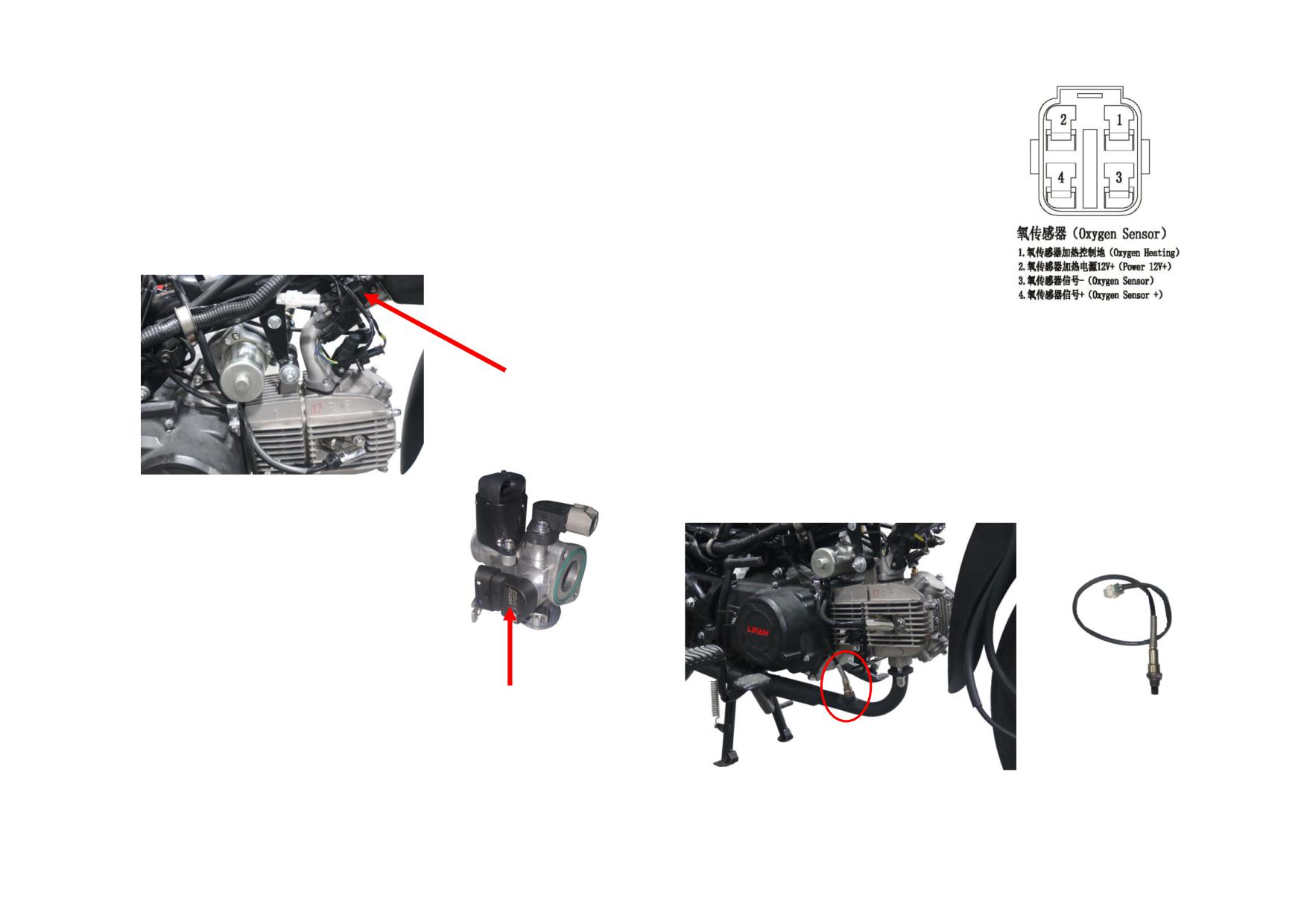
Malfunction Mode
5.3.7 Oxygen Sensor
Connecting pipe is blocked, damagesl or falls off; invalid sensor due to
Function
short-circuit or break-circuit, water entering, mechanical failure.
The oxygen sensor is used in the feedback
5.3.5 Stepper Motor
system of EFI device. It can realize the closed
The stepper motor receives directives from ECU to control the amount of air
loop to improve the control accuracy of ECU
intake when the engine is idling. If the cylinder head temperature is not less
to air/fuel ratio, and test the oxygen content in
than 90℃, and the engine speed is around 1500r/min (1600 r/min for scooter),
exhaust gas to determine whether the air and
the stepper motor steps range from 20-60 (depending on the vehicle model).
fuel were completely burned, so as to ensure
that the three-way catalytic converter has the
maximum conversion efficiency of HC, CO
and NOX in exhaust gas.
Installation Location
STEPPER MOTOR
The oxygen sensor should be installed on the muffler or cylinder head, and can
meet the specified temperature range. The installation location should be as
close to the engine as possible and its angle to the horizontal plane should be ≥
20°.
5.3.6 IAT Sensor
NOTE: It is necessary to ensure that the installation seat is well sealed.
Function
The IAS sensor is a negative temperature
coefficient (NTC) thermistor, uses its
temperature sensitive characteristics to convert
the change of ambient temperature into the change
of thermistor resistance, then converts this change
into a voltage signal and outputs to ECU through
a voltage divider circuit.
IAT SENSOR
Malfunction Mode
Incorrect thermistor resistance, short-circuit or break-circuit sensor.
5-7
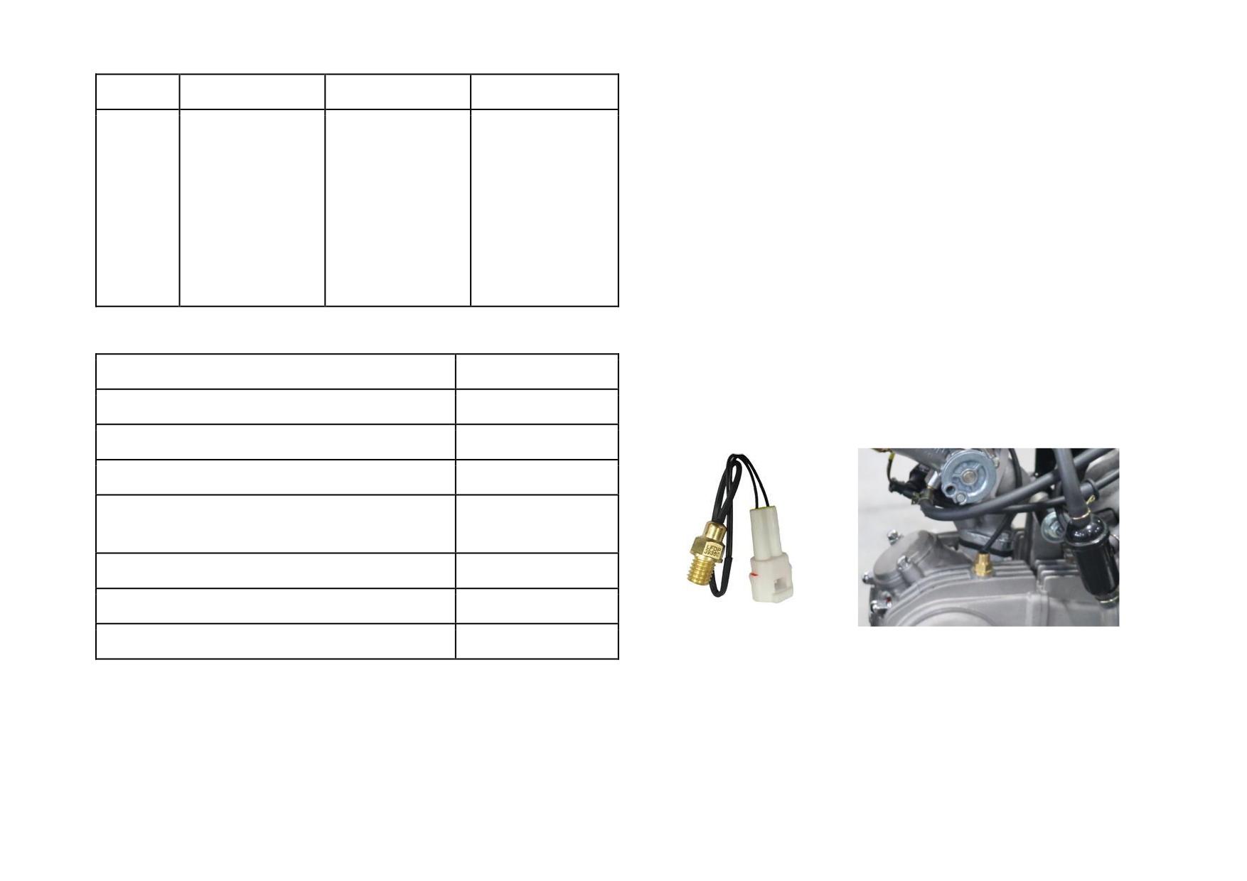
short-circuit or break-circuit of heating/sensing circuit.
Parts
Reference Range
Trouble
Remark
1. 0V (short- circuit
5.3.8 Cylinder/Water Temperature Sensor
Unstable idle
of oxygen sensor)
Function
speed, not fluent
Large fluctuation
2. 0.44V (open-
The cylinder/water temp. sensor is a negative temperature coefficient (NTC)
fuel supply, high
Oxygen
between 0.01-0.99V
circuit of oxygen
thermistor, which uses its temperature sensitive characteristics to convert the
fuel consumption,
sensor
after stabilizing the
sensor)
change of engine temperature into the change of thermistor resistance, then
engine speed
throttle for 40s
3. 0.42-0.44V
converts this change into ECU through a voltage signal. The thermistor
decreases sharply
(engine is not
resistance value decreases as the engine temperature rises, but it is not a linear
at stable throttle
started)
relationship. The NTC thermistor is installed in a copper heat conducting
sleeve.
Characteristic Parameters
Installation Location
Item
Value
The sensor is mounted on the cylinder head, cylinder block or thermistor.
Storing temperature (℃)
-40~100
Thread of cylinder temp. sensor: M10×1.5
Taper thread of water temp. sensor: M10×1.25
Probe tube end working temp. (℃)
200~850
Connecting plug temp. (℃)
<120
Max. allowable working temp. of probe tube when
930
heating (℃)
Rated voltage (V)
12
Continuous working voltage (V)
12~14
Test voltage (V)
13
Malfunction Mode
Failure of heating elements, failure of sensing elements, broken ceramic tube,
5-8
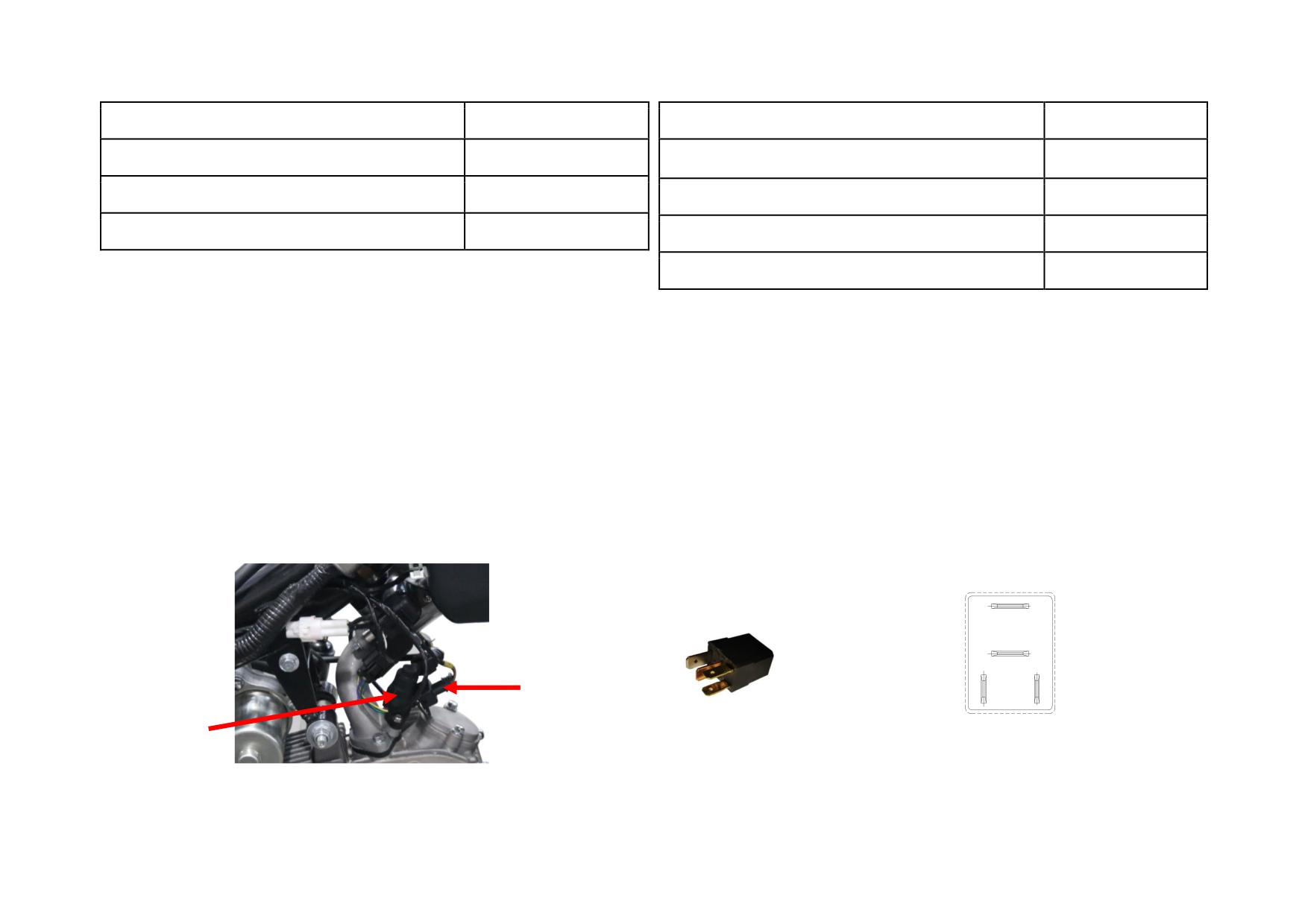
Characteristic Parameters
Characteristic Parameters
Item
Value
Item
Value
Storing temperature (℃)
-40~130
Working voltage (V)
8~16
Running temperature (℃)
-40~200
Acceptable internal fuel pressure (kPa)
<1100
Rated resistance at 20℃
2.5 ±5%
Continuous working temp. of injector (℃)
-40~110
Malfunction Mode
Resistance range of injector at 20 ℃ (Ω)
12~16
Incorrect resistance, short-circuit or break-circuit of sensor.
Malfunction Mode
Blocked injector, break-circuit or short-circuit of magnetic coil, failure of
5.3.9 Injector & Oil Rail
injector due to vibration, oil leaks from seal ring.
1) Injector
2) Oil rail
Function
Function
The injector injects fuel in a specified time in accordance with the directive of
The oil rail is of simple structure, used to inject fuel from oil hose to injector,
ECU, thereby providing fuel to engine and atomizing it.
and has the function of storing oil and pressure, reducing fluctuation in oil
NOTE: Different types of fuel injector are used in various motorcycles, so they
pressure.
cannot be shared.
Installation Location
Installation Location
It is mounted on the intake manifold or throttle valve body with a bolt as shown
It is installed on the intake manifold and straight length from the intake valve is
above.
70-120 (mm).
5.3.10 Relay
OIL PUMP
RELAY OUTPUT
Pin Purpose
12V (+)
12V BATTERY (+)
ELECTRONIC
ECU-OIL PUMP
DOOR LOCK 12V
RELAY CONTROL
POWER (+)
INJECTOR
LINE
OIL RAIL
Installation Location
The relay is installed on the engine or frame.
5-9
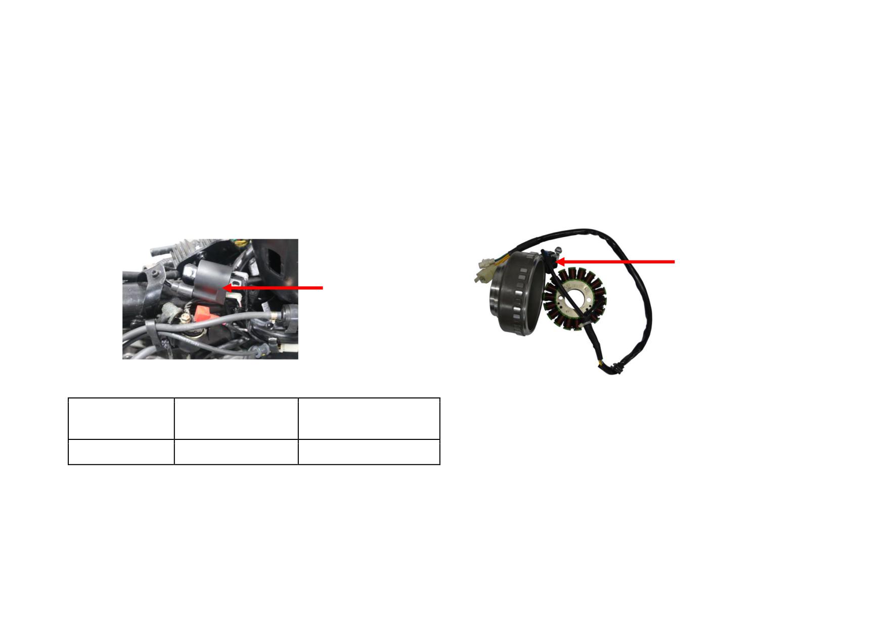
Malfunction Mode
5.3.12 Engine Speed Sensor
Break-circuit or short-circuit of relay, poor contact or failure of relay due to
Function
vibration.
It is used in EFI device to monitor the engine crankshaft speed and output
voltage-frequency signals to the electronic controller to make judgments on
5.3.11 Ignition Coil
engine’s operating conditions. At the same time, together with the missing teeth
Function
position of the sensor signal, it can detect the crankshaft position, so as to
It is used in the EFI device to receive ECU ignition signal and provide high
determine the TDC position which can be one of the parameters for calculating
pressure to ignite the spark plug, so as to ignite air/fuel mixture in the cylinder
the ignition advance angle.
through high pressure connection wire and spark discharge from the spark plug.
Installation Position
Installation Location
It is located in the position of the original carburetor.
The ignition coil is installed on the frame.
ENGINE SPEED SENSOR
IGNIITION COIL
Characteristic Parameters
36-2 TEETH MAGNETO ROTOR
Working voltage
Primary resistance (Ω)
Secondary resistance (KΩ)
Malfunction Mode
(V)
Large clearance between sensor and teeth plate, loose teeth plate, iron fillings
6-16
4.5±10%
18.5±10%
on the sensor, damaged leading wire, short-circuit or break-circuit of sensor..
Malfunction Mode
Break-circuit of primary windings, secondary windings are short-circuited by
breakdown.
5-10
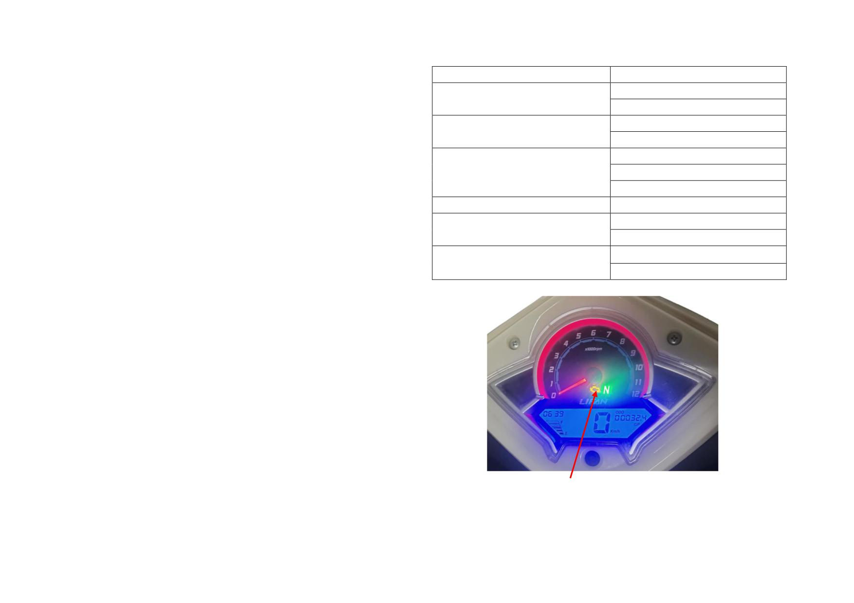
5.4 MALFUNCTION DIAGNOSIS
5.4.1 Self-diagnosis Function
Sensor
MIL Flash Code
(1) After the vehicle enters the working state, ECU controls the electronic
31
IAT Sensor
system components to work and detects them in real time. Once malfunction
32
occur to the components, the system will turn on the engine MIL to warn. When
41
Intake Air Manifold Pressure
the system fails, ECU will start the backup function of “emergency control
42
plan”.
51
(2) Malfunction can be classified into “steady-state malfunction” and
Oxygen Sensor
52
“occasional malfunction” (such as temporary break-circuit or poor contact of
53
couplers). Steady-state malfunction: a malfunction identified by the ECU exists
Crankshaft Position Sensor
63
for a longtime. Occasional malfunction: a malfunction exists by chance.
21
5.4.2 MIL Function
TPS
22
(1) The MIL is set in the vehicle instrument as shown in the picture. All sensors
11
and actuators in the system can be detected. If a fault is detected, the MIL will
Engine Temp. Sensor
12
flash in different frequency to remind the driver or maintenance personnel to
read the fault code, and the fault can also be read by the fault diagnostic
scanner.
(2) When the key switch is turned on but the engine is not started, the MIL will
be on for 2~3s, if the current system has no fault, the MIL will be off. Otherwise,
it will flash in regular code rule as the table below.
(3) Flashing rule: A fault code is composed of two digits which stand for the
number of flashes. There is an interval between the light on and the next time.
The decimal digits flash first and longer than the single digits, the two digital
flashes have an interval of about 1.5s. When more than two faults are read, the
interval time will be longer.
Clear Malfunction in ECU: Use the fault diagnostic scanner to call up the
Clear Fault item and select it, and then click the OK button.
NOTE: After troubleshooting, the fault information stored in the ECU should
MIL
be cleared.
5-11
5.4.3 Diagnosis Reference Value
Item
Reference Range
Fault and Troubleshooting
Remark
1. When the angle is large, counterclockwise turn the idle speed bypass
screw by 1/4 of a lap, accelerate the throttle 3 times and wait for 15s to
It is normal to occasionally
Ignition advance
check, repeat above operation until it returns to the standard value.
deviate from the normal range,
-0.2-(+6.0) °
angle
2. When the angle is small, clockwise turn the idle speed bypass screw by
and the idle speed can be
stable at this time.
1/4 of a lap, accelerate the throttle 3 times and wait for 15s to check, repeat
above operation until it returns to the standard value.
1. When the time is longer, problems maybe: blocked injector port, oxygen
sensor continues to report dilute mixture, insufficient fuel pump pressure or
battery voltage, air leaks from muffler gasket or mounting seat of oxygen
Working condition: idling at
Injection time
2.5-3.5 ms
sensor.
warm engine
2. When the time is shorter, problems maybe: oxygen sensor continues to
report thick mixture or faulty sensor oxygen, fuel pump pressure is higher
than normal value.
Large fluctuation from 0.01 to
1. When the value keeps below 0.44V, the air-fuel mixture in combustion
0V: short-circuit of oxygen
0.99V (after the engine works
chamber is too lean.
sensor
Oxygen sensor
normally for 40s)
0.44V: open-circuit of oxygen
2. When the value keeps above 0.6V, the air-fuel mixture in combustion
sensor
chamber is too rich.
1. A fault may occur when temperature of the water/cylinder temperature
The temperature rises as the
sensor changes little as the engine temperature rises greatly.
Water/cylinder
engine runtime increases, but peak
2. A fault may occur if the temperature continues to show a certain value
Replace the sensor
temp. sensor
temperature should not be more
or greatly exceeds the actual value.
than 120℃.
3. The water/cylinder temperature sensor reads abnormal data, the fan
keeps on rotating or fails to work.
5-12
A fault may occur if the read differs significantly from the actual
IAT sensor
Vary as the air temperature
Replace the sensor
temperature.
1. Unstable idle speed, slow response in acceleration;
Mounting screw of the sensor
TPS
0-80%
2. Opening at idle speed condition shows 0 or 0.39%.
cannot rotate freely.
The atmospheric pressure
1. No idle speed, slow response in acceleration;
needs to be calculated
IAP sensor
Idle speed: about 30Kpa
2. Faulty magneto speed sensor, air leaks from connecting hose or poor
according to the altitude of the
contact of circuit.
actual region.
1. Check the charging device and circuits at low voltage;
Battery voltage
13.5-14.5V
Check at stable idle speed
2. Check the rectifier at high voltage.
NOTE: When the altitude is higher than 1Km, the idle speed adjustment cannot refer to the TEV opening, but the target idle speed (1600±100) r/min, (1300±100)
r/min and the ignition advance angle (-0.2~6)
°C. It is also possible to determine whether the bypass bolt adjustment is proper by accelerating or decelerating the
throttle. When the cylinder head temperature reaches (90±3)
°C and the throttle keeps at 4000r/min, loosen or rotate the throttle rapidly after 15s to determine
whether the engine speed can return to the target idle speed by engine sound. If the fuel returns slowly, it indicates that air supply of the bypass bolt is too large. If
there is an engine flameout at fuel return or fuel adding, air supply of the bypass bolt is too small. In both cases, the bypass bolt needs to be adjusted to ensure the
vehicle in best condition.
Target idle speed for scooter: 1600±100 r/min
Target idle speed for other vehicles: 1300±100 r/min
5-13
5.5 TROUBLESHOOTING
TROUBLE
POSSIBLE CAUSES
SOLUTION
1. Check the battery, fuse, system relay, wire harness and
No power in the system or at the fuel pump plug
emergency switch for normal work.
2. If above components are in good condition, check the ECU.
Fuel pump fails to work
Damaged fuel pump
Replace the fuel pump
Fuel pump is electrified.
Low voltage (<8V )
Check the battery, system relay and couplers for normal work.
Lack of fuel
Add fuel and amount should not be less than 3L.
Low battery voltage
Check if the battery, voltage regulator and magneto need to
charge.
No fuel
pressure or
Seriously blocked fuel passage
Check the fuel filter strainer for block
low fuel
Engine
pressure
Failure of fuel pressure regulator
Replace the fuel pump
fails or is
Leakage of fuel passage
Broken hose or loose hose clamp, replace them if necessary
hard to
start, is
Fuel pump wires in reverse connection
Reconnect
easy to
flameout
Fuel
Fuel in spark plug is wet (fuel is not burned)
Remove and dry the spark plug, or replace it
pump can
Creepage of spark plug insulator or abnormal
Replace the spark plug or spark plug cap
work
jump-spark
Sparks
Improper spark plug gap
Adjust it to standard value
occur in
Normal fuel
ignition
Poor contact or creepage of spark plug cap
Adjust or replace
pressure
coil at
Faulty ignition circuit or poor contact of
Check the wires, TPS installation condition and various
high
couplers
couplers.
pressure
Damaged water/cylinder temp. sensor or IAT
Replace
sensor
Blocked injector
Clean or replace
5-14
Poor contact of ignition circuits
Check and repair the circuits
No spark
Large gap between speed sensor (exciter coil)
Adjust the gap
or broken
and rotor convex plate
spark in
ignition
Damaged ignition coil or spark plug
Replace
coil
at
high
Creepage of ignition coil output
Replace
pressure
Faulty ECU or poor contact of couplers
Check or replace
Clogged air cleaner or too much dusty on it
Clean off
Heavy carbon deposits in combustion chamber and
Clear away
exhaust muffler
Worn piston rings, piston and cylinder, large gaps
Replace
Lack of power
Slipping clutch friction disc
Adjust or replace the clutch friction disc
Clogged fuel passage, lower fuel pressure or poor quality
Check the fuel pump, injector and fuel for good condition
fuel
Faulty water/cylinder temp. sensor or faulty oxygen
Check and replace
sensor
Poor quality fuel
Use higher quality fuel
Engine failure
Repair
Large fuel consumption
Faulty water/cylinder temp. sensor
Check and replace
Faulty oxygen sensor
Check and replace
Clogged air cleaner or too much dusty on it
Clean off
5-15
Battery voltage< 12V
Check the battery and charging system
Poor contact of ECU or injector couplers
Check and troubleshooting
Air leaks from throttle valve body or connecting hose of
Check the paper gasket, O-ring, clamp or connecting hose for
inlet pipe
air leakage
Dirties in throttle valve body or clogged air cleaner
Clean off
Check the fuel tank for enough fuel, check the fuel filer and
Influent fuel passage
fuel passage for clogging
Expired fuel or poor quality fuel
Use unleaded gasoline with RQ92 or higher
Loose spark plug
Tighten up
Unstable idle speed
Improper spark plug gap
Adjust to stand value
Poor contact or creepage of spark plug cap
Adjust or replace
Creepage or abnormal jump-spark of spark plug
Replace the spark plug
insulator
Small valve gap or engine failure
Adjust the valve gap or check the engine
Air leaks from muffler gasket or oxygen sensor
Check and troubleshooting
mounting seat
Air leaks from connecting pipe of idle speed gulp valve
Check or adjust
or TEV opening isn’t suitable
Invalid oxygen sensor or little air supply of idle speed
Check, adjust or replace
gulp screw
5-16
Faulty water/cylinder temp. sensor
Check and replace
Failure of acceleration at mid/high speed
or engine speed drops rapidly when
Faulty oxygen sensor
Check and replace
holding the throttle for about 5s
Insufficient fuel pressure of fuel pump
Check and replace
Poor contact of circuit
Check
Rectifier is unable to charge
Check and replace
Insufficient power generated from magneto coil
Check and replace
Low voltage of EFI system (<12V)
Aging battery can’t store power
Repair, maintain or replace
Avoid driving at low speed for a long time or connecting with
Insufficient battery power due to heavy load
high-power electrical appliances
Faulty water temp. sensor
Check and replace
The fan keeps rotating or fails to
rotate
Faulty fan relay
Check and replace
Engine is easy to stall when releasing
Large TEV opening or little idle gulp air
Adjust the adjusting screw of idle gulp valve
the throttle
Damaged or leaking negative pressure switch cap of
Check and replace
carbon canister
Large intake air of idle gulp valve screw
Adjust
Too high idle speed
Air leaks from inlet pipe or O-ring
Check and repair
Broken or leaking desorption tube, idle gulp valve,
Replace the abnormal rubber hose
negative pressure pipe, etc
5-17
Poor contact of spark plug and cap, or water entering in
Check and repair
Air leaks from oxygen sensor mounting seat
Check and repair
Running with sudden rush
Faulty oxygen sensor
Replace
Improper TEV opening and abnormal idle gulp air
Adjust
Air leaks from muffler gasket
Repair
Clutch friction discs are burned and worn.
Replace
Large gap of clutch cable, not disengaged clutch
Adjust
Difficulties in gear-shifting
Tight drive chain
Adjust
Check the gearshift cam, gearshift shaft, main shaft &
Failure of engine gear-shifting device
countershaft, gearshift drum and gearshift pedal
Faulty engine speed sensor (exciter coil)
Replace
Large gap between engine speed sensor (exciter coil)
Adjust
and rotor convex plate
Poor contact of main cable with ignition coil coupler
Check and adjust
No spark of ignition coil
Poor contact of ECU and main cable, or faulty ECU
Check and replace
Poor contact of engine speed sensor and main cable
Check and repair
coupler
Descriptions: When EFI vehicles have problems, please refer to the maintenance method of the carburetor vehicle and check it from the following aspects:
1. Check the vehicle for sufficient fuel (must be≥3L with good quality) and normal fuel supply.
2. Check the ignition system for normal work.
3. Check the engine cylinder or normal pressure.
4. Check the engine intake system for fluent flowing.
5-18
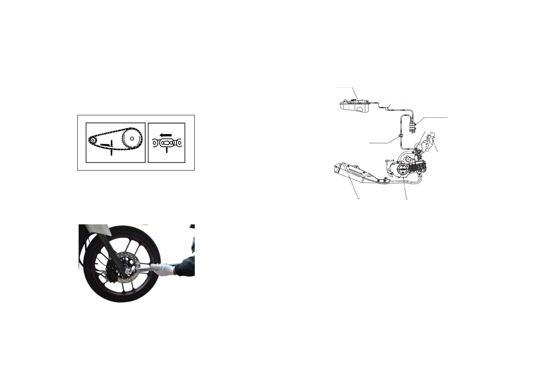
CHAPTER 6 SERVICE
6.1 ROUTINE MAINTENANCE AND ADJUSTMENT
6.1.1 Maintenance of Drive Chain
6.1.3 Fuel System
Check the drive chain for wear and slack. Lubricate the chain if it seems to be
FUEL TANK
dry. Support the motorcycle with center stand, press the chain between two
sprockets to check its slack. Adjust the slack to be 10~20mm.
ANTI-ROLL VALVE
ACTIVE CARBON CANISTER
OIL/GAS SEPARATOR
CHECK VALVE
AIR CLEANER
6.1.2 Adjustment
Loosen the locknuts of rear axle and drive chain adjuster; turn the adjusting bolt
MUFFLER
ENGINE
until the left and right adjuster align with the same mark: finally, check and
tighten up the rear axle locknut with tightening torque 60~80 N
m.
6.1.3.1 Removal, Installation and Maintenance
1) Turn off the ignition switch.
2) Unlock the seat with a key and turn over the seat cushion.
3) Remove the fuel tank cover, check the seal ring and replace it if it deforms or
damages.
4) Remove the fuel pump and check the filter hose and strainer, clean them if
necessary.
5) Remove the fuel tank, check the fuel tank interior and clean the tank if
necessary.
6) Check all rubber hoses in fuel system for bend, breach and aging, adjust or
replace them if necessary.
6-1
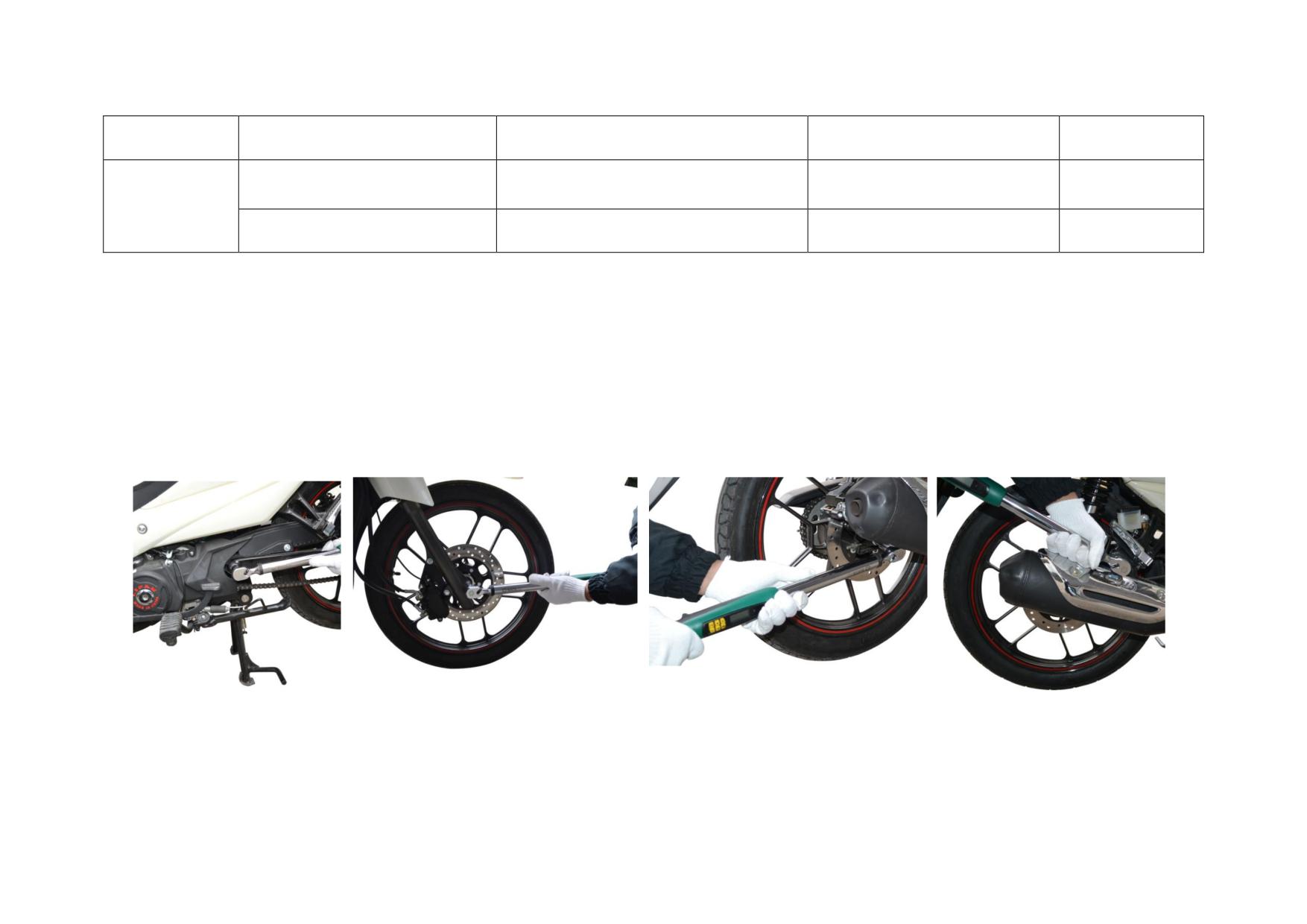
6.1.3.2 Troubleshooting to Fuel Tank
Description
Damage Form
Trouble
Service
Remark
Cracks on the fuel tank due to
Fuel tank leaks.
Repair or replace
/
erosion
Fuel Tank
No fuel supply, engine fails to start.
Clean the vent of fuel cock
Vent of fuel cock is clogged.
/
6.1.4 Principle of Secondary Air-Induction System and Crankcase EGR System
The crankcase EGR system has a gas channel between the crankcase and the air cleaner, and sets up an oil/gas separator. Exhaust gas in the
crankcase passes through the oil/gas separator, then enters the air cleaner, throttle valve body assembly, and returns to the engine combustion
chamber for combustion, avoiding direct discharge of exhaust gas into the atmosphere in the crankcase, thus reducing atmospheric pollution.
Precautions during use and maintenance: The oil/gas separator should be cleaned regularly, and it is recommended to do so every 3 months.
6.1.5 Check of Fasteners
Check all fasteners such as rear fork shaft, front/rear wheel with a torque spanner as pictures below.
REAR FORK SHAFT
FRONT WHEEL
REAR WHEEL
MUFFLER
TIGHTENING TORQUE:
TIGHTENING TORQUE:
TIGHTENING TORQUE:
TIGHTENING TORQUE:
45~65N.m
60~80N.m
60~80N.m
24~30N.m
6-2
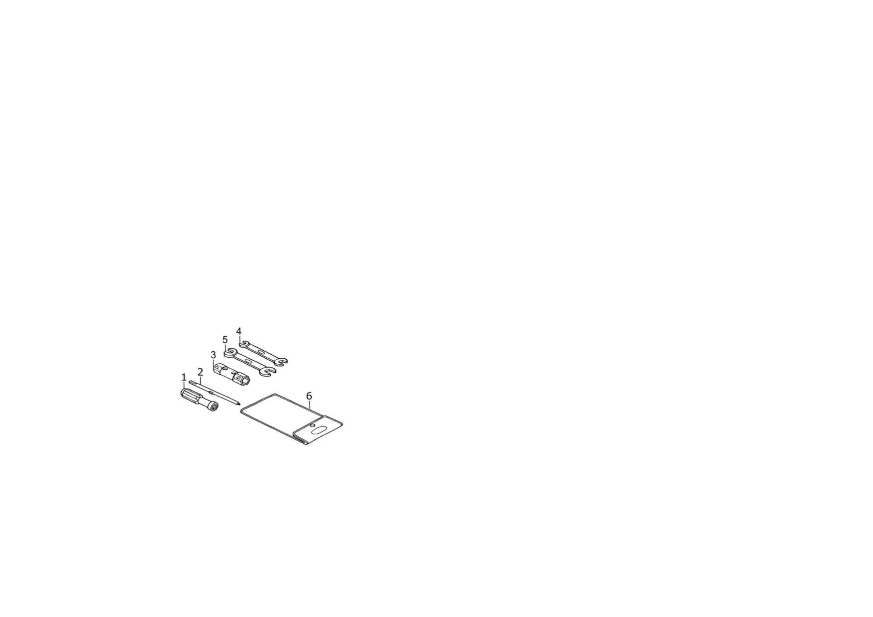
6.2 PRE-RIDE INSPECTION
Check the following before each ride:
1. Engine oil level--Add engine oil if necessary, check for leakage.
2. Fuel level--Refuel if necessary, check for leakage.
3. Front and rear brakes--Check for operation, adjust free play if necessary.
4. Tyres--Check condition and pressure.
5. Battery--Check its power.
6. Accelerator--Check for accelerator operation, cable connection and free play of handle, adjust or replace if necessary.
7. Lights and horn--Check that headlights, taillight, parking (position) light, winkers, indicators and horn function properly.
8. Drive chain--Check chain slack and engine oil condition, adjust, lubricate or replace if necessary.
9. All nut, bolts and fasteners--Check that the parts are mounted securely.
10. Steering system--Check for its flexibility and reliability.
6.3 GENERAL MAINTENANCE
6.3.1 Tool Kit
1. Screw driver grip
1pc
2. Double-ended screw driver
1pc
3. Spark plug wrench, 16#×18#
1pc
4. Open-ended spanner, 8mm×10mm 1pc
5. Open-ended spanner, 13mm×15mm 1pc
6. Tool bag
1pc
Manufacturer’s Vehicle Repair and Maintenance Information
Web site addresses referred to
Account: n.a.
Password: n.a.
6-3
6.3.2 Maintenance Schedule
FREQUENCY
Item
ODOMETER READING, km (Note ②)
SERVICE ITEM
Period
1,000km
4,000km
8,000km
12,000km
Note
·
Fuel line system
Ⅰ
Ⅰ
Ⅰ
·
Fuel filter
C
C
C
C
·
Throttle operation system
Ⅰ
Ⅰ
Ⅰ
Ⅰ
Air cleaner element
Note ①
C
C
C
Spark plug
Ⅰ
Ⅰ
Ⅰ
Ⅰ
Valve clearance
Ⅰ
Ⅰ
Ⅰ
Ⅰ
Engine oil
Yearly
R
Every 2,000Km after 500km & 1000km
Engine oil strainer
Yearly R
C
·
Cam chain slackness
A
A
A
A
Drive chain
Ⅰ、L
Ⅰ、L
Ⅰ、L
Ⅰ、L
Battery
Monthly
Ⅰ
Ⅰ
Ⅰ
Ⅰ
Brake shoes/pad wear
Ⅰ
Ⅰ
Ⅰ
Brake system
Ⅰ
Ⅰ
Ⅰ
Ⅰ
·
Stop light switch
Ⅰ
Ⅰ
Ⅰ
Ⅰ
·
Headlight adjustment
Ⅰ
Ⅰ
Ⅰ
Ⅰ
Clutch
Ⅰ
Ⅰ
Ⅰ
Ⅰ
Side stand
Ⅰ
Ⅰ
Ⅰ
·
Suspension
Ⅰ
Ⅰ
Ⅰ
Ⅰ
·
Nut, bolt and fasteners
Ⅰ
Ⅰ
Ⅰ
Ⅰ
··
Wheels/spokes
Ⅰ
Ⅰ
Ⅰ
Ⅰ
··
Steering, handlebar and bearing
Ⅰ
Ⅰ
6-4
Maintenance work should be performed in light of Maintenance Schedule.
Letters in the table indicate as follows:
I:Inspect and clean, adjust, lubricate or replace if necessary.
C:Clean
R:Replace
A:Adjust
L:Lubricate
NOTES: ① Clean more frequently when riding in unusual wet or dusty areas;
② At higher odometer readings, still follow the frequency intervals established in this manual.
6.4 STORAGE
1. Empty fuel inside the fuel tank, fuel hose and other passages.
2. Remove the spark plug and pour appropriate engine oil into its hole. Turn off the ignition switch, and crank several revolutions to scatter evenly the oil on the
cylinder wall.
3. Remove the drive chain, clean and lubricate it.
4. Lubricate all of the controlling cables.
5. Support the motorcycle with the center stand, store it in the atmosphere and dry place.
6. Seal the muffler outlet with a plastic bag to prevent moisture from entering.
7. Coat all surfaces of bare metal with a thin layer of rust-resisting oil if the motorcycle is to be exposed to wet or salty air.
8. Remove the battery and store it in a dry, cool and well-ventilated plate. Charge the battery once every 30-day.
6.5 UNPACKING
Place the packed motorcycle on a level ground. Unpack the case with a special tool to prevent scratching the body surface. This done, check to see that all parts of the
motorcycle are intact and good, check the allotted tools for completeness.
6-5