Land Rover Engine 2.0 Litre L Series. Manual - part 15


  Index      Land Rover     Land Rover Engine 2.0 Litre L Series Diesel - service manual 2000 year


Search            


Content   ..  13  14  15 


Land Rover Engine 2.0 Litre L Series. Manual - part 15


ENGINE

50

OVERHAUL

Cylinder block

1. Check that all oilways are clear and that oil

restrictor located in oilway to cylinder head is
fitted below face of cylinder block.

2. Check that main bearing cap, crankshaft rear

oil seal housing and cylinder head locating
dowels are fitted.

3. Check core plugs for leakage and corrosion,

replace as necessary.

NOTE: Seal replacement core plugs and
main oil gallery plug on rear of cylinder
block with Loctite 577, tighten main oil

gallery plug to 45 Nm. Seal dipstick tube in
cylinder block with Loctite 638.

Pistons and connecting rods - refit

1. Lubricate cylinder bores, pistons, rings and

crankshaft big-end journals with engine oil.

2. Lubricate new big-end bearing shells with

engine oil and fit to connecting rods and
bearing caps.

3. Check that piston ring gaps are positioned at

120

°

to each other and away from thrust - left

hand side of piston - viewed from front of
piston.

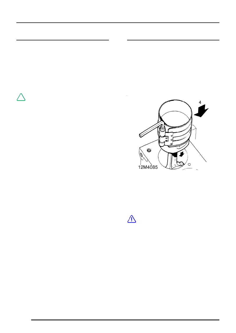
4. Fit suitable piston ring clamp to each piston in

turn and ensuring that pistons are in their
correct fitted order and that the arrow on piston
crown and the cast boss above the big-end is
facing towards front of cylinder block, push
pistons into their respective cylinder bores.

CAUTION: Ensure that connecting rods do
not contact cylinder bores.

5. Do not pull connecting rods fully down cylinder

bores at this stage.

6. Check that cut-out in each piston skirt is

positioned above oil squirt jet location.

7. Ensure oil squirt jets are clear and that roll pins

are inserted in jet housings.

ENGINE

OVERHAUL

51

8. Position oil squirt jets in cylinder block ensuring

that roll pins are inserted in locating holes.

9. Apply Loctite 275 to threads of new banjo

bolts.

CAUTION: Do not allow Loctite to enter oil
hole in banjo bolts.

10. Fit and tighten banjo bolts to 12 Nm.
11. Fit crankshaft and big-end bearings.

ENGINE

DATA, TORQUE & TOOLS

1

ENGINE DATA

Oil pump
Outer rotor to body clearance

0.05 to 0.10 mm

. . . . . . . . . . . . . . . . . .

Rotor lobe clearance

0.025 to 0.12 mm

. . . . . . . . . . . . . . . . . . . . . . . . .

Outer rotor end float

0.03 to 0.08 mm

. . . . . . . . . . . . . . . . . . . . . . . . .

Relief valve spring free length

38.9 mm

. . . . . . . . . . . . . . . . . .

Camshaft
Camshaft end-float

0.51 mm - max.

. . . . . . . . . . . . . . . . . . . . . . . . . .

Camshaft bearing clearance

0.043 to 0.094 mm

. . . . . . . . . . . . . . . . . . .

Camshaft timing belt tensioner spring free length

65 mm

. . .

Tappets
Tappet outside diameter

34.959 to 34.975 mm.

. . . . . . . . . . . . . . . . . . . . . .

Cylinder head
Cylinder head maximum warp

0.10 mm

. . . . . . . . . . . . . . . . . .

Cylinder head bolt length

243.41 mm

. . . . . . . . . . . . . . . . . . . . . .

Valve springs
Free length

37.0 mm

. . . . . . . . . . . . . . . . . . . . . . . . . . . . . . . .

Valves
Valve stem diameter:

Inlet

6.907 to 6.923 mm

. . . . . . . . . . . . . . . . . . . . . . . . . . . . . . . . . . . .

Exhaust

6.897 to 6.913 mm

. . . . . . . . . . . . . . . . . . . . . . . . . . . . . . . . .

Valve stem to guide clearance - maximum:

Inlet

0.056 mm

. . . . . . . . . . . . . . . . . . . . . . . . . . . . . . . . . . . .

Exhaust

0.066 mm

. . . . . . . . . . . . . . . . . . . . . . . . . . . . . . . . .

Valve face angle

45

°

to 45

°

30’

. . . . . . . . . . . . . . . . . . . . . . . . . . . .

Valve head stand down:

Inlet

1.45 mm

. . . . . . . . . . . . . . . . . . . . . . . . . . . . . . . . . . . .

Exhaust

1.35 mm

. . . . . . . . . . . . . . . . . . . . . . . . . . . . . . . . .

Valve guides:

Inside diameter after reaming

6.950 to 6.963 mm

. . . . . . . . . . . . . . . . .

Fitted length above cylinder head

61.1 to 61.7 mm

. . . . . . . . . . . . . .

Valve seat inserts:

Seat angle

Inlet

60

°

. . . . . . . . . . . . . . . . . . . . . . . . . . . . . . . . . . . .

Exhaust

58

°

to 62

°

. . . . . . . . . . . . . . . . . . . . . . . . . . . . . . . . .

Insert diameter

Inlet

35.697 mm

. . . . . . . . . . . . . . . . . . . . . . . . . . . . . . . . . . . .

Exhaust

31.05 to 31.55 mm

. . . . . . . . . . . . . . . . . . . . . . . . . . . . . . . . .


Content   ..  13  14  15