Land Rover Engine 2.0 Litre L Series. Manual - part 7
ENGINE
18
OVERHAUL
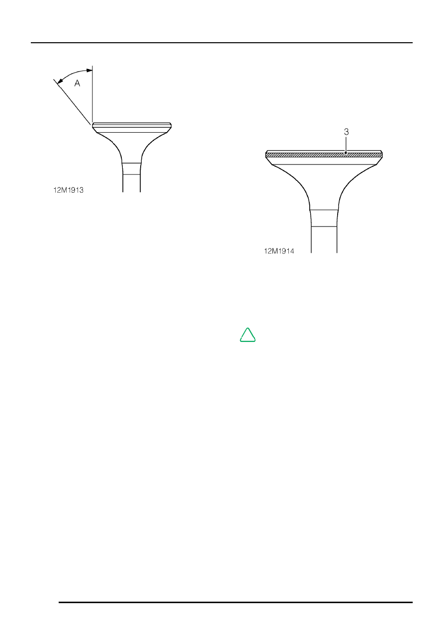
3. Check face angle A of each valve, renew any
valve with incorrect face angles, do not attempt
to recut.
Valve face angle - Inlet and exhaust = 45
°
to
45
°
30’.
Lapping-in valves
1. Lap each valve to its seat using grinding paste.
2. Apply Prussian Blue to valve seat, insert valve
into guide and press it firmly, without rotating,
on to seat.
3. Remove valve and check that a continuous,
even line of Prussian Blue has been
transferred on to valve face; continue
lapping-in valve as necessary.
NOTE: Line does not have to be across
whole width of valve face.
4. On completion of lapping-in, check valve head
stand down. See this section