Land Rover Engine 1.8 Litre K Series. Manual - part 12


  Index      Land Rover     Land Rover Engine 1.8 Litre K Series - service manual 2000 year


Search            


Content   ..  10  11  12  13   ..


Land Rover Engine 1.8 Litre K Series. Manual - part 12


ENGINE

34

OVERHAUL

3. Lap each valve to seat using fine grinding

paste.

4. Apply Prussian Blue to valve seat, insert valve

and press it into position several times without
rotating. Remove and check valve for even and
central seating:
Seating position shown by blue should be in
centre of valve face.

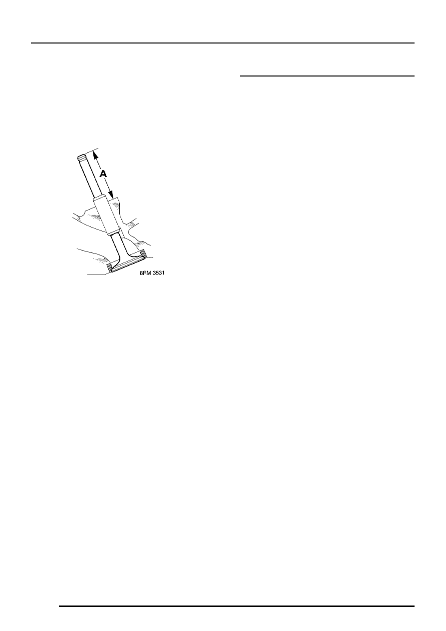
5. Check valve stem fitted height A:

New = 38.93 to 39.84 mm
Service limit = 40.10 mm

If valve stem fitted height is above service limit, fit
new valve and re-check, if still over limit, renew
valve seat insert.

6. Remove all traces of grinding paste on

completion.

Valves - assembling

1. Using LRT-12-071, fit new valve stem oil

seals.

2. Lubricate valve stems and assemble valves,

using tool LRT-12-034 and adaptor
LRT-12-034/1, to compress valve spring.

3. Use a wooden dowel and mallet, lightly tap top

of each valve assembly two or three times to
seat valves and collets.

4. Lubricate outside of tappets and fit tappets in

original bores.

ENGINE

OVERHAUL

35

Camshafts - refit

1. Lubricate bearings and fit camshaft(s) and

position drive pin for 90

°

BTDC as follows:

Inlet pin at 4 o’clock.
Exhaust pin at 8 o’clock.

Camshaft carrier and oil seals - refit

1. Ensure 2 locating dowels are fitted in camshaft

carrier.

2. Apply continuous, thin beads of sealant, Part

Number GUG 705963GM to paths on cylinder
head as shown then spread to an even film
using a roller.

CAUTION: Ensure sealant is kept clear of
tappet oil feed holes and lubrication
grooves in carrier and that assembly is

completed within 20 minutes.

3. Lubricate camshaft cams and journals with

engine oil.

CAUTION: Do not lubricate oil seal
running surfaces.

ENGINE

36

OVERHAUL

4. Fit camshaft carrier and progressively tighten

bolts, in sequence shown to 10 Nm.

NOTE: Exhaust camshaft front oil seal
illustrated.

5. Fit new camshaft oil seals using oil seal

protection sleeve 12-203 and oil seal fitting
tool LRT-12-148A.

NOTE: Front oil seals are coloured
BLACK, rear oil seals are coloured RED.

CAUTION: Oil seals must be fitted dry. Do
not use tool LRT-12-148 for fitting seals as
they will not be positioned correctly within

the recess.

6. Fit blanking plate, fit and tighten bolts to 25

Nm.

Cylinder head - refit

CAUTION: If crankshaft has been rotated,
check that timing mark on crankshaft
timing gear is aligned with flange on oil

pump and that tool LRT-12-145 is locking
flywheel.

1. Check cylinder head bolts in oil rail. See

Cylinder head bolt inspection - Renew bolts
as necessary.

2. Check that 2 locating ring dowels are fitted in

cylinder block.

CAUTION: The type of ring dowel fitted
must be maintained. A nylon ring dowel
must not be used in place of a steel ring

dowel.

3. Oil cylinder head bolts, under head and

threads.

4. Remove cylinder liner retainer clamps

LRT-12-144.

CAUTION: Do not rotate crankshaft until
cylinder head bolts are fitted.

5. Fit new cylinder head gasket DRY, with

identification markings facing upwards, on to
cylinder block.

CAUTION: Take care not to damage
sealing faces of gasket.

6. Using assistance, fit cylinder head on to

cylinder block carefully locating ring dowels.

7. Carefully enter cylinder head bolts in their

original fitted locations; DO NOT DROP. Lightly
tighten bolts.

ENGINE

OVERHAUL

37

8. Temporarily fit timing gears to camshafts, fit

but do not fully tighten bolts.

9. Using tool 12-182, rotate both camshafts

clockwise to gain access to bolts:
Early engines:- Bolts 1 and 2
Later engines fitted with modified camshafts:-
Bolts 3 and 4

10. Tighten cylinder head bolts progressively in

sequence shown to 20 Nm.
Use a felt tip pen to mark position of radial
mark on each bolt head.
Tighten all bolts in sequence shown through
180

°

Tighten all bolts in sequence shown through
another 180

°

and align mark.

CAUTION: If any bolt is overtightened,
back off 90

°

and re-align.

11. Upon completion of tightening sequence,

position camshafts with inlet pin at 4 o’clock
and exhaust pin at 8 o’clock; remove timing
gears.

CAUTION: Ensure camshafts do not rotate
when gears are removed.

12. Automatic timing belt tensioner:- Fit tensioner

pillar bolt and tighten to 25 Nm.

NOTE: Do not fit timing belt automatic
tensioner until timing belt is fitted.

13. Fit camshaft cover and timing gears.
14. Fit new spark plugs, tighten to 25 Nm.

Camshaft cover and timing gears - refit

1. Clean mating surfaces and inside of camshaft

cover.
If necessary, wash oil separator elements in
suitable solvent and blow dry.

2. Fit new camshaft cover gasket dry, to camshaft

carrier, with either ’TOP’ mark towards the inlet
manifold or ’EXHAUST MAN SIDE’ towards
exhaust manifold.

Camshaft cover with pillar bolts

3. Fit camshaft cover on to camshaft carrier, fit 13

bolts at positions 1 and 4 to 15. Fit pillar bolts
at positions 2 and 3. Tighten all bolts in
sequence shown to 10 Nm.

Camshaft cover with ’cast-in’ supports

4. Fit camshaft cover on to camshaft carrier, fit

bolts and tighten in sequence shown to 10 Nm.


Content   ..  10  11  12  13   ..