Land Rover Engine 2.0 Litre T Series. Manual - part 7


  Index      Land Rover     Land Rover 2.0 Litre T Series Engine - service manual 1997 year


Search            


Content   ..  5  6  7  8   ..


Land Rover Engine 2.0 Litre T Series. Manual - part 7


ENGINE

OVERHAUL

13

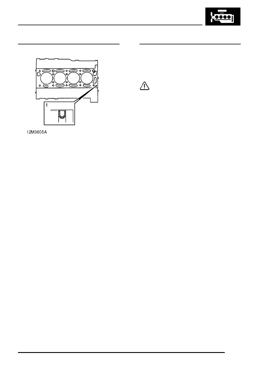
Oil restrictor - fitting

1. Insert oil restrictor in oil passage in cylinder

block ensuring that top of restrictor is
positioned below gasket face of block.

Valve springs - inspection

1. Check condition of valve springs:

Free length = 46.25 mm
Fitted length = 37.0 mm
Load - valve closed = 255

±

12 N

Load - valve open = 560

±

22.5 N

CAUTION: Valve springs must be replaced
as a complete set.

ENGINE

14

OVERHAUL

Valves and guides - inspection

NOTE: Two types of exhaust valve may be
fitted, standard valves A in illustration or
carbon break valves, B. Carbon break

valves may be identified by the machined profile
C on the valve stem. To prevent exhaust valves
sticking, carbon break valves together with the
later type valve guides - see following illustration
should always be fitted whenever standard
valves or early type guides are to be replaced.

NOTE: Exhaust valve guides illustrated

NOTE: Two types of valve guide may be
fitted and before removing guides,
reference should be made to the above

illustration to identify the type of guide. The early
type of guide, A in illustration has a radiussed
top and a fitted height of 12.0 mm. The later type,
B in illustration, has a flat, chamfered top and a
fitted height of 10.3 mm. Additionally, exhaust
valve guides are counterbored at the exhaust
valve end of the guide. Replacement valve
guides will all be of the later type and these,
together with carbon break exhaust valves
should be fitted in engine sets to cylinder heads
whenever the early type of guide and standard
exhaust valves are to be replaced.

ENGINE

OVERHAUL

15

NOTE: Later type exhaust valve guide
illustrated

1.

Early type exhaust valve guides fitted: Remove
carbon deposits from exhaust valve guides
using Rover tool 18G 1773.

2.

Later type exhaust valve guides fitted:
Remove carbon deposits from exhaust valve
guides using Rover tool 18G 1773 and from
valve guide counterbores using Rover tool 18G
1765.

NOTE: Tools must be inserted into guide
from combustion face side of cylinder
head.

3. Remove carbon from valves, inlet valve guides

and valve seat inserts. Ensure all traces of
carbon are removed on completion.

NOTE: Later type exhaust valve guide
illustrated

4. Remove carbon from valves, inlet valve guides

and valve seat inserts. Remove all loose
particles of carbon on completion.

5. Check existing valve stem and head diameters.
6. Check valve stem to guide clearance using

new valves.

7. Renew valves and guides as necessary.

Valve head diameter A:
Inlet = 31.7 to 31.95 mm
Exhaust = 29.2 to 29.43 mm

Valve stem diameter B:
Inlet = 7.09 to 7.10 mm
Exhaust = 7.07 to 7.09 mm

ENGINE

16

OVERHAUL

8. Check installed height of each valve.

Valve installed height C:
Inlet and exhaust = 43.4 mm max.

NOTE: If valve installed height exceeds
dimension given, valve/valve seat insert
must be replaced.

9. Valve stem to guide clearance D:

Inlet = 0.04 to 0.06 mm
Service limit = 0.09 mm
Exhaust = 0.06 to 0.07 mm
Service limit = 0.10 mm

10. Valve guide internal diameter E:

Inlet and exhaust = 7.137 to 7.162 mm

Valve guides - renew

1. Heat cylinder head evenly to 100

°

C.

WARNING: Wear protective gloves when
handling cylinder head.

2. Place cylinder head face downwards and using

a piloted mandrel, press valve guide towards
combustion face side for a distance of 2.0 mm.

3. Invert cylinder head and remove all traces of

carbon from periphery of valve guide.

4. Re-heat cylinder head to 100

°

C.

5. Using a piloted mandrel, press valve guide out

from the combustion face side of the cylinder
head.

NOTE: The tapered portion of the valve
guide is either plain or has 1, 2 or 3
grooves machined around the

circumference. Additionally, later type exhaust
valve guides are counterbored at the
combustion face end of the guide. When
replacing guides it is essential to ensure that a
plain guide is replaced with a guide having 2
grooves and a guide having 1 groove is replaced
with a guide having 3 grooves.

6. Re-heat cylinder head to 100

°

C.


Content   ..  5  6  7  8   ..