Land Rover Engine 2.0 Litre T Series. Manual - part 6


  Index      Land Rover     Land Rover 2.0 Litre T Series Engine - service manual 1997 year


Search            


Content   ..  4  5  6  7   ..


Land Rover Engine 2.0 Litre T Series. Manual - part 6


ENGINE

OVERHAUL

9

3. Remove inlet and exhaust camshafts.

CAUTION: Suitably identify each camshaft
to its fitted position, do not interchange
camshafts.

4. Remove and discard 2 oil seals from each

camshaft.

5. Using a stick magnet, remove 16 tappets.

CAUTION: Store tappets in their fitted
order and invert to prevent oil loss.

Camshafts - inspection

NOTE: Carry out camshaft inspection after
removal of valves and springs.

1. Clean camshafts and bearing journals in

camshaft carriers and cylinder head.

2. Inspect cams and camshaft bearing journals,

replace camshaft(s) if scoring, pitting or
excessive wear is evident.

3. Inspect bearing journals in cylinder head and

camshaft carriers, replace components if
scoring, pitting or excessive wear is evident.

4. Remove all traces of oil from bearing journals

in cylinder head, camshaft carriers and
camshafts.

5. Position camshafts on cylinder head.
6. Position a piece of Plastigage across each

camshaft bearing journal.

7. Fit camshaft carriers, fit securing bolts and

working from the centre outwards,
progressively tighten bolts to 25 Nm. Do not
rotate camshafts.

8. Remove camshaft carrier securing bolts,

remove carriers.

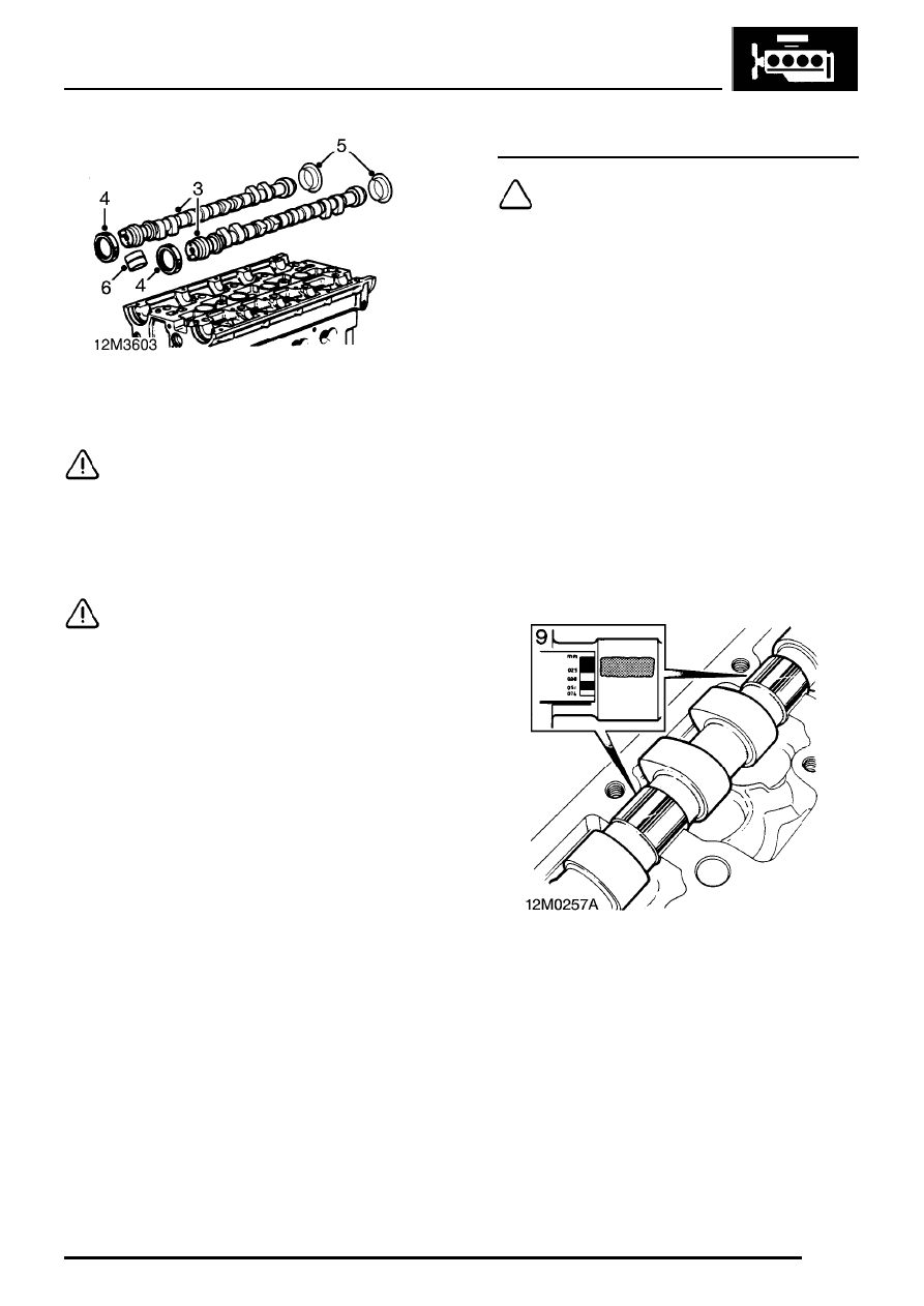
9. Measure widest portion of Plastigage on each

bearing journal and from dimensions obtained,
calculate camshaft bearing clearance.
Camshaft bearing clearance = 0.060 to 0.094
mm
Service limit = 0.15 mm

ENGINE

10

OVERHAUL

10. If bearing clearance is excessive, fit new

camshaft(s) and repeat check; if excessive
clearances still exist, renew cylinder head and
camshaft carriers.

11. Remove all traces of Plastigage using an oily

rag.

12. Transfer drive pins from old camshafts to new

with split fitted towards centre of camshaft.

Valves and springs - remove

1. Using a hollow drift, tap each valve spring cap

to free collets.

2. Position cylinder head on its exhaust manifold

face.

3. Using tool LRT-12-034 and adaptor

LRT-12-034/1, compress inlet valve spring.

4. Remove 2 collets using a magnet.

5. Release tool LRT-12-034 and remove valve,

valve spring cap and valve spring.

ENGINE

OVERHAUL

11

6. Using tool LRT-12-071, remove and discard

valve stem oil seal.

7. Repeat above operations for remaining inlet

valves.

CAUTION: Keep valves, springs, caps and
collets in fitted order.

8. Position cylinder head on its inlet manifold

face.

9. Remove exhaust valves and valve stem oil

seals using the above procedures.

Cylinder head - inspection

1. Clean all traces of gasket material from

cylinder head using suitable gasket removal
spray and a plastic scraper. Remove sealant
using suitable solvent.

CAUTION: Take great care not to damage
gasket face of head. If locating dowels
have been removed with cylinder head,

they must be refitted in cylinder block.

2. Thoroughly clean cylinder head, blow out

oilways and coolant passages.

3. Ensure camshaft carrier locating dowels are

fitted.

4. Check cylinder head for damage, cracks or

burning.

5. Check condition of 10 core plugs, renew any

plug showing signs of cracks, corrosion or
weeping, seal new plugs using Loctite 601.

6. Check cylinder head face for warping.

Longitudinal warp = 0.1 mm max.
Transverse warp = 0.1 mm max.
Diagonal warp = 0.1 mm max.

CAUTION: If warping exceeds the figures
given, a new cylinder head must be fitted.
Cylinder heads must not be refaced.

7. Check cylinder head height measured from

face of head to camshaft carrier face.
Cylinder head height = 135.0 to 135.1 mm

ENGINE

12

OVERHAUL

8. Check gasket face of cylinder head for

scratches or indentations paying particular
attention to the shaded areas in the above
illustration.

Cylinder head gasket selection

1. If scratches or indentations exist, fit cylinder

head gasket coated with black sealant.

NOTE: This gasket was fitted as standard
to all engines up to engine no. 128817. It
will be necessary to fit the oil restrictor in

the cylinder block.

2. If no scratches or indentations exist, fit cylinder

head gasket which is of multi-layer steel
construction.

NOTE: This gasket is fitted as standard to
all engines from engine no. 128817 and
may be fitted to all engines prior to this

number provided the above conditions are met.
It will be necessary to remove the oil restrictor -
if fitted from the cylinder block.


Content   ..  4  5  6  7   ..