Land Rover Engine 2.0 Litre T Series. Manual - part 3


  Index      Land Rover     Land Rover 2.0 Litre T Series Engine - service manual 1997 year


Search            


Content   ..  1  2  3  4  ..


Land Rover Engine 2.0 Litre T Series. Manual - part 3


ENGINE

10

DESCRIPTION AND OPERATION

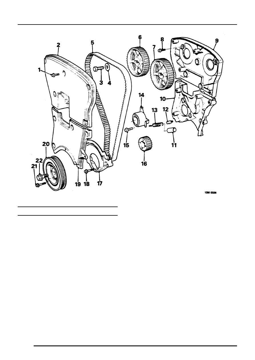
TIMING BELT COMPONENTS

1. Bolt - timing belt upper cover
2. Timing belt upper cover
3. Bolt - camshaft timing gear
4. Plain washer
5. Timing belt
6. Inlet camshaft timing gear
7. Exhaust camshaft timing gear
8. Bolt - upper timing cover backplate
9. Upper timing cover backplate

10. Lower timing cover backplate
11. Tensioner spring sleeve

12. Anchorage bolt
13. Tensioner spring
14. Tensioner pulley
15. Tensioner clamp bolt
16. Crankshaft timing gear
17. Timing belt lower cover
18. Bolt - timing belt lower cover
19. Timing belt centre cover
20. Crankshaft pulley
21. Crankshaft pulley/timing gear bolt
22. Crankshaft pulley bolt

ENGINE

DESCRIPTION AND OPERATION

11

OPERATION

The ’T’ Series engine is a four cylinder, water cooled
unit comprising a cast iron cylinder block, aluminium
alloy cylinder head and twin aluminium alloy
camshaft carriers.

The cylinder block incorporates direct bored,
siamesed cylinder bores which provide good
structural rigidity. The crankshaft is carried in five
main bearings, end-float being controlled by thrust
washers positioned each side of the centre main
bearing. The main bearing caps are located to the
cylinder block by dowels; the bearing shells fitted to
Numbers 1, 3 and 5 bearings are fully grooved whilst
those fitted to Numbers 2 and 4 bearings are plain.

The cylinder head carries twin camshafts operating
four valves per cylinder via hydraulic tappets.
Exhaust valves fitted to later engines are of the
’carbon break’ type. A machined profile on the valve
stem removes any build-up of carbon in the
combustion chamber end of the valve guide thereby
preventing valves from sticking. These valves may
be fitted to all early engines. Both camshafts are
driven by the timing belt and run directly in journals
line bored in the cylinder head and camshaft
carriers. The plastic camshaft covers are bolted to
the camshaft carriers.

ENGINE

12

DESCRIPTION AND OPERATION

The aluminium alloy, tin coated pistons have two
compression and an oil control ring and are secured
to the connecting rods by semi-floating gudgeon
pins which are an interference fit in the small-end
bush. Gudgeon pins are offset towards the thrust
side of the pistons to reduce frictional drag.

Plain, big-end bearing shells are fitted to each
connecting rod.

The internally toothed timing belt is driven from a
gear which is keyed to the crankshaft, belt tension
being controlled by a semi-automatic tensioner.

The trochoidal type oil pump is mounted on the front
of the engine and carries the crankshaft front oil
seal. Drive to the pump is via a Woodruff key
inserted in the crankshaft.

ENGINE

DESCRIPTION AND OPERATION

13

Lubrication

Oil is drawn from the pressed steel sump through a
strainer (1) and into the oil pump (2); excess
pressure being relieved by a pressure relief valve (3)
integral with the pump. The low oil pressure sensor
(4) is screwed into the adaptor and registers the oil
pressure in the main oil gallery on the outflow side of
the filter. Pressurised oil passes through the full flow
oil filter (5) to internal drillings in the crankshaft
where it is directed to each main bearing and to the
big-end bearings via Numbers 1, 3 and 5 main
bearings (6). An internal drilling in the cylinder block
directs oil, via a restrictor - if fitted (7) to the cylinder
head where it passes through further internal
drillings to the hydraulic tappets and camshaft
journals (8).

Gudgeon pin and small-end bush lubrication is by
splash from the big-end bearings.

Crankcase ventilation

With the exception of two hoses connected from the
inlet camshaft cover to the inlet manifold and throttle
housing, all crankcase ventilation is via internal
voids in the cylinder head and block. The inlet
camshaft cover carries a wire gauze flame trap
located over the breather pipe connections.


Content   ..  1  2  3  4  ..