Jeep Gladiator (2024 year). Manual in english
CHARGING & OUTLETS
13
OFFROAD FEATURES
31
INTRODUCTION
Electrical Power Outlets
13
Axle Lock (Tru-Lok) Front And Rear -
OWNER HANDBOOK INTRODUCTION
4
Power Inverters - If Equipped
14
If Equipped
31
SYMBOLS KEY
4
USB/AUX Control
15
Axle Lock (Tru-Lok) Rear Only -
CUSTOMER ASSISTANCE
5
INSTRUMENT CLUSTER
16
If Equipped
31
FCA US LLC Customer Center
5
Getting To Know Your Instrument Cluster . . 16
Electronic Sway Bar Disconnect -
FCA Canada Customer Care
5
Instrument Cluster Display Location And
If Equipped
32
Mexico
5
Controls
17
Off Road+ - If Equipped
33
Puerto Rico And US Virgin Islands
5
Warning Lights And Messages
17
Roadside Assistance
5
INTERIOR COMFORT SETTINGS
22
EXTERIOR
Customer Assistance For The Hearing Or
Climate Controls
22
EXTERIOR OVERVIEW
34
Speech Impaired (TDD/TTY)
5
Automatic Climate Control Descriptions And
Service Contract
6
EXTERIOR CAMERA VIEWS
35
Functions
22
Back Up Camera
35
Warranty Information
6
Automatic Temperature Control (ATC) . . . 23
Trailcam System - If Equipped
35
Ordering and Accessing Additional Owner’s
Climate Voice Recognition
23
Information
6
HOOD
35
Front Heated Seats - If Equipped
24
Change Of Ownership Or Address
7
To Open The Hood
35
Power Front Seats Adjustment -
General Information
7
To Close The Hood
36
If Equipped
24
TAILGATE
36
Head Restraints
24
INTERIOR
Opening
36
LIGHTING OPERATION
25
REFUELING THE VEHICLE
36
INTERIOR OVERVIEW
8
Headlight Switch
25
STARTING AND OPERATING
9
Automatic High Beams
26
EMERGENCY
Keyless Enter ‘n Go™ - Passive Entry
9
Automatic Headlights
26
Stop/Start System
9
WINDSHIELD WIPERS & WASHERS
26
SOS AND ASSIST SYSTEM - IF EQUIPPED . . 38
MULTIMEDIA & PHONE CONNECTIVITY
10
Windshield Wiper Operation
26
JACKING AND TIRE CHANGING
40
Uconnect System
10
Preparations For Jacking
40
CRUISE CONTROL SYSTEMS
27
Uconnect Settings
10
Adaptive Cruise Control (ACC)
27
Jack Location
40
Pair/Delete A Device
11
Spare Tire Location And Removal
40
GARAGE DOOR OPENER (HOMELINK®)
29
Apple CarPlay®
11
Jacking Instructions
41
Troubleshooting Tips
30
Android Auto™
12
JUMP STARTING
43
PARKING ASSISTANCE
30
Uconnect Voice Recognition
12
Preparations For Jump Starting
44
ParkSense Rear Park Assist System -
Off-Road Pages
12
Jump Starting Procedure
44
If Equipped
30
2
FREEING A STUCK VEHICLE
45
TOWING A DISABLED VEHICLE
46
Towing In An Emergency
47
SPECIFICATIONS
ENGINE COMPARTMENT OVERVIEW
50
3.6L Engine
50
FLUID CAPACITIES
51
ENGINE FLUIDS AND LUBRICANTS
51
CHASSIS FLUIDS AND LUBRICANTS
52
SERVICING AND MAINTENANCE
52
Maintenance Plan
52
Oil Change Reset - If Equipped
53
Engine Break-In Recommendations
53
TRAILER TOWING WEIGHTS (MAXIMUM
TRAILER WEIGHT RATINGS)
53
3

OWNER HANDBOOK INTRODUCTION
SYMBOLS KEY
Thank you for choosing Jeep. This Owner Handbook has been prepared to
WARNING!
These statements apply to operating
help you quickly become acquainted with important features of your
procedures that could result in a
vehicle. It contains most things you will need to operate and maintain your
collision, bodily injury and/or death.
vehicle, including emergency information.
CAUTION!
These statements apply to procedures
This handbook also illustrates and describes the operation of certain fea-
that could result in damage to your
vehicle.
tures and equipment that come either standard or optional on your vehicle.
It may include a description of features and equipment that your vehicle is
NOTE:
A suggestion which will improve
not equipped with. FCA US LLC reserves the right to make changes in
installation, operation, and reliability. If
not followed, may result in damage.
design and specifications and/or make additions to or improvements to its
products without imposing any obligation upon itself to install them on
TIP:
General ideas/solutions/suggestions on
products previously manufactured.
easier use of the product or functionality.
PAGE REFERENCE ARROW
Follow this reference for additional
Mobile App:
information on a particular feature.
FOOTNOTE
Supplementary and relevant information
pertaining to the topic.
To access your complete Owner’s Manual online: www.mopar.com
To order a hard copy of your Owner’s Manual, visit:
If you do not read the entire Owner’s Manual, you may miss important
information. Observe all Cautions and Warnings.
4
INTRODUCTION
CUSTOMER ASSISTANCE
FCA US LLC CUSTOMER
ROADSIDE ASSISTANCE
FCA US LLC and its authorized dealers are vitally
CENTER
Call 1-800-521-2779 or visit
interested in your satisfaction. We want you to be
P.O. Box 21-8004
chrysler.rsahelp.com(USA)
happy with our products and services.
Call 1-800-363-4869 or visit fca.roadsideaid.com
Auburn Hills, MI 48321-8004
Warranty service must be done by an authorized
(Canada)
Phone: (877) 426-5337
dealer. We strongly recommend that you take the
Available: 24 Hours, 7 Days A Week
vehicle to an authorized dealer for non-warranty
FCA CANADA CUSTOMER CARE
Your vehicle’s VIN number is required to receive
service as well. FCA US LLC's authorized dealers
covered services.
P.O. Box 1621
have the facilities, factory-trained technicians,
Windsor, Ontario N9A 4H6
• Flat Tire Service
special tools, and the latest information to ensure
the vehicle is fixed correctly and in a timely
Phone: (800) 465-2001 English /
• Out Of Gas/Fuel Delivery - This service is lim-
ited to two occurrences in a 12-month period.
manner.
(800) 387-9983 French
Up to two gallons of fuel will be provided by a
If your authorized dealer is unable to resolve the
service provider.
MEXICO
concern, you may contact an FCA US LLC
Customer Assistance center.
Customer Relations Office
• Battery Jump Assistance
Any communication to an FCA US LLC Customer
Av. Prolongacion Paseo de la Reforma, 1240
• Lockout Service
Assistance center should include the following
Sante Fe C.P. 05109
• Towing Service
information:
Mexico, CDMX
CUSTOMER ASSISTANCE FOR
• Owner's name and address
In Mexico City: 800-505-1300
THE HEARING OR SPEECH
• Owner's telephone number (home, mobile, and
Outside Mexico City: +(52) 55 50817568
office)
IMPAIRED (TDD/TTY)
• Authorized dealer name
PUERTO RICO AND US VIRGIN
To assist customers who have hearing difficulties,
• Vehicle Identification Number (VIN)
ISLANDS
FCA US LLC has installed special Telecommuni-
cation Devices for the Deaf (TDD) equipment at
• Vehicle delivery date and mileage
Customer Service
its customer centers. Any hearing or speech
FCA Caribbean LLC
impaired customer, who has access to a TDD or a
P.O. Box 191857
conventional teletypewriter (TTY) in the United
States, can communicate with FCA US LLC by
San Juan 00919-1857
dialing 1-800-380-2479.
Phone: (877) 426-5337
INTRODUCTION
5
Canadian residents with hearing difficulties who
questions about the service contract, call the
Use this QR code to access your
require assistance can use the special needs relay
FCA's Service Contract National Customer
digital experience.
service offered by Bell Canada. For TTY users,
Hotline at (800) 465-2001 English /
dial 711. For Voice callers, dial 1-800-855-0511 to
(800) 387-9983 French).
connect with a Bell Relay Service operator.
Mopar Vehicle Protection Plans offer valuable
Scan me
protection against repair costs after your vehicle
SERVICE CONTRACT
warranties have expired. Mopar Vehicle Protec-
You may have purchased a service contract for a
tion plans are the ONLY vehicle extended protec-
ORDERING AND ACCESSING
vehicle to help protect you from the high cost of
tion plans authorized, endorsed and backed by
ADDITIONAL OWNER’S
unexpected repairs after FCA US LLC's New
FCA US LLC to provide additional protection
INFORMATION
Vehicle Limited Warranty expires. The Mopar®
beyond your vehicle's warranty.
Vehicle Protection plans are the ONLY vehicle
To order the following manuals, you may use
FCA US LLC is not responsible for any service
extended protection plans authorized, endorsed
either the website or the phone numbers listed
contract you may have purchased from another
and backed by FCA US LLC to provide additional
below.
manufacturer. If you require service after the FCA
protection beyond your vehicle’s warranty. If you
US LLC New Vehicle Limited Warranty expires,
Service Manuals
purchased a Mopar® Vehicle Protection Plan, you
please refer to the contract documents, and con-
These comprehensive Service Manuals provide a
will receive Plan Provisions and an Owner Identi-
tact the person listed in those documents.
complete working knowledge of the vehicle, sys-
fication Card in the mail within three weeks of
We appreciate that you have made a major
tem, and/or components and is written in
the vehicle delivery date. If you have any ques-
investment when you purchased the vehicle. An
straightforward language with illustrations, dia-
tions about the service contract, call FCA US
authorized dealer has also made a major invest-
grams, and charts.
LLC’s Service Contract National Customer
ment in facilities, tools, and training to assure
Diagnostic Procedure Manuals
Hotline at 1-800-521-9922.
that you are absolutely delighted with the owner-
Diagnostic Procedure Manuals are filled with dia-
For Canadian residents, you may have purchased
ship experience.
grams, charts and detailed illustrations. These
additional coverage with an extended service
manuals make it easy to find and fix problems on
contract. FCA Canada Inc. stands fully behind its
WARRANTY INFORMATION
computer-controlled vehicle systems and fea-
service contracts. Be sure that the one you buy is
To access your warranty information online, visit
tures. They show exactly how to find and correct
a genuine Canada Inc. service contract. We are
www.mopar.com/om (US) or
problems, using step-by-step troubleshooting
not responsible for other companies’ contracts. If
and drivability procedures, proven diagnostic
you purchased a contract other than a genuine
www.owners.mopar.ca/fr (Canada).
tests and a complete list of all tools and
FCA Canada Inc. service contract and you have a
equipment.
problem, you will have to contact the administra-
tor of that contract for resolution. If you have any
6
INTRODUCTION
To order a digital copy of your Service or Diag-
Make sure to include the following:
Le présent appareil est conforme aux CNR d`In-
nostic Procedure manuals, visit:
novation, Science and Economic Development
• Date of Sale (mm/dd/yy)
www.techauthority.com (US and Canada).
applicables aux appareils radio exempts de
• Vehicle Identification Number (17 Character ID
licence. L'exploitation est autorisée aux deux
Owner's Manuals
located on top left of the instrument panel)
conditions suivantes:
These Owner's Manuals have been prepared with
• Exact Odometer Reading
1. L'appareil ne doit pas produire de brouillage,
the assistance of service and engineering special-
• First and Last Name
et
ists to acquaint you with specific FCA vehicles.
• Phone Number
2. L'utilisateur de l'appareil doit accepter tout
To access your Owner's Information online, visit
• Street Address, City, State and Zip Code
brouillage radioélectrique subi, même si le
www.mopar.com/om (US) or
brouillage est susceptible d'en compromettre
www.owners.mopar.ca/en/ (Canada).
• Email Address
le fonctionnement.
*Applies to US residents only.
Or visit:
La operación de este equipo está sujeta a las
www.techauthority.com to order physical copies
GENERAL INFORMATION
siguientes dos condiciones:
of Owner’s Manuals (US).
The following regulatory statement applies to all
1. Es posible que este equipo o dispositivo no
Owner's Manuals, Radio Manuals and Warranty
Radio Frequency (RF) devices equipped in this
cause interferencia perjudicial y
Information Books can be ordered through
vehicle:
2. Este equipo o dispositivo debe aceptar cual-
Archway at:
This device complies with Part 15 of the FCC
quier interferencia, incluyendo la que pueda
1-800-387-1143 (Canada)
Rules and with Innovation, Science and Economic
causar su operación no deseada.
Development Canada license-exempt RSS stan-
CHANGE OF OWNERSHIP OR
NOTE:
dard(s). Operation is subject to the following two
ADDRESS
Changes or modifications not expressly
conditions:
approved by the party responsible for compli-
*If you have purchased this vehicle used or have
1. This device may not cause harmful interfer-
ance could void the user’s authority to operate
changed your address, please provide the follow-
ence, and
the equipment.
ing information and mail to:
2. This device must accept any interference
FCA US LLC
received, including interference that may
P.O. Box 21-8008
cause undesired operation.
Auburn Hills, MI 48321-8004
INTRODUCTION
7
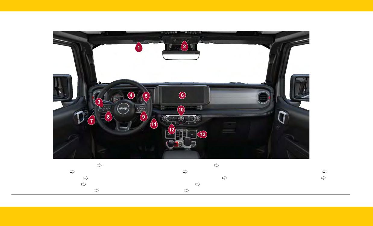
INTERIOR OVERVIEW
1 - Garage Door Opener (HomeLink®)
page 29
6 - Uconnect Radio Screen Display
page 10
11 - Keyless Push Button Ignition
2 - Assist & SOS Buttons
page 38
7 - Headlight Switch
page 25
12 - Stop/Start Off Switch
page 9
3 - Instrument Cluster Controls
page 17
8 - Uconnect Voice Command Buttons
page 12
13 - USB/AUX Media Hub
page 15
4 - Instrument Cluster Display
page 16
9 - Cruise Control Buttons
page 27
5 - Windshield Wipers and Washers
page 26
10 - Climate Controls
page 22
8
INTERIOR
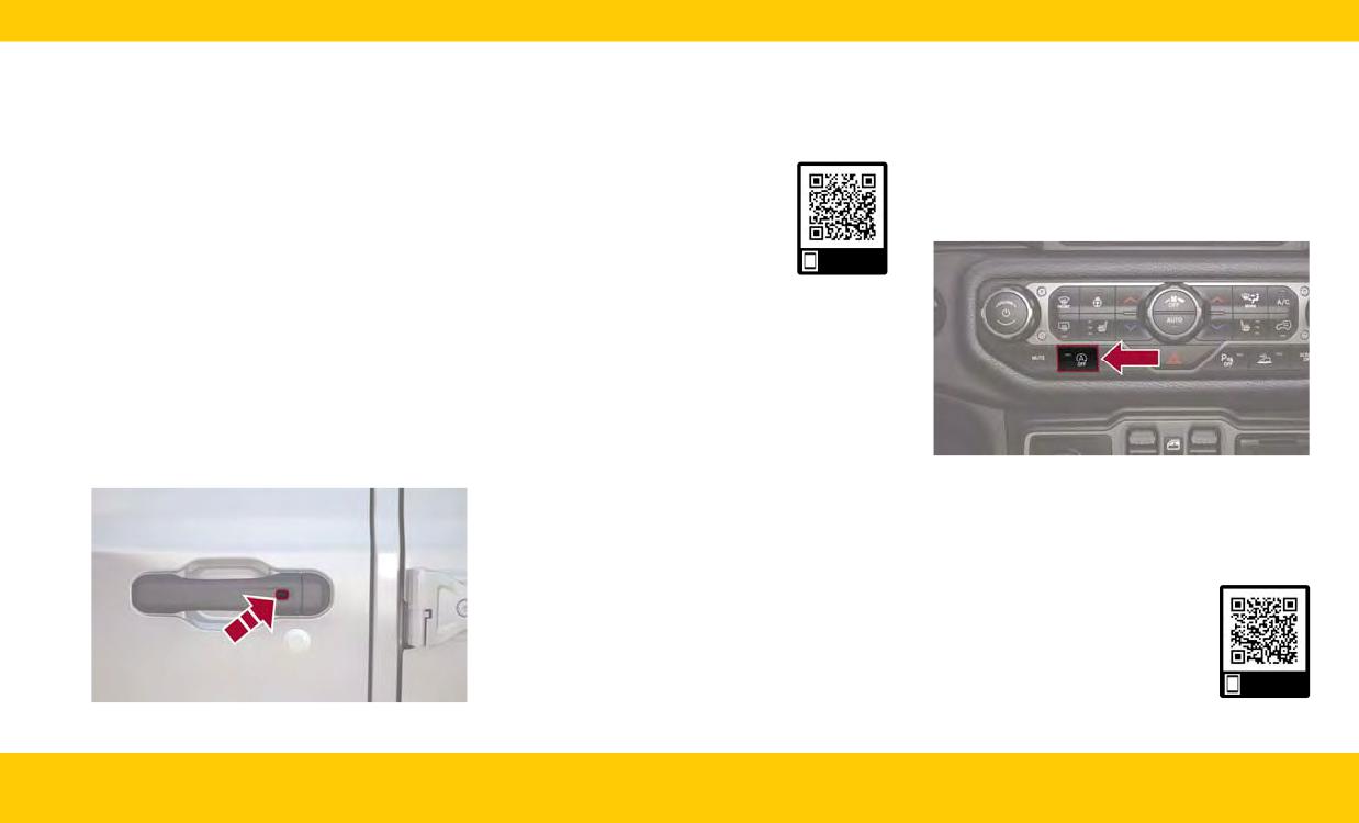
STARTING AND OPERATINGNOTE:
How To Turn Off The Stop/Start
• DO NOT grab the door handle when pushing
System
KEYLESS ENTER ‘N GO™ -
the lock button. This could unlock the door(s).
Did you know you can manually turn off your
PASSIVE ENTRY
Stop/Start system?
• Be sure to keep the vehicle key fob with you.
Just push the Stop/Start OFF switch to turn off
Keyless Enter ‘n Go™ - Passive Entry allows you
Use this QR code to access your
this feature. The light on the switch will illuminate
to lock and unlock the vehicle’s door(s) and tail-
digital experience.
and the “STOP/START OFF” message will appear
gate without having to push the key fob lock or
in the instrument cluster display.
unlock buttons.
To Unlock/Lock The Vehicle’s Doors And
Scan me
Tailgate
With a valid Passive Entry key fob with you, grab
STOP/START SYSTEM
the handle to unlock the vehicle. Grabbing the
driver’s door handle will unlock the driver door
The Stop/Start function is designed to save fuel
automatically. Grabbing the passenger door
and reduce emissions. The system will stop the
handle will unlock all doors and the tailgate
engine automatically during a vehicle stop if the
automatically.
required conditions are met. Releasing the brake
pedal, pressing the accelerator pedal, or releas-
With a valid Passive Entry key fob on you, push
ing the clutch pedal (on manual transmission)
the Passive Entry lock button on the door handle
will automatically restart the engine.
to lock the vehicle.
Stop/Start OFF Switch
NOTE:
The Stop/Start system will reset itself back to the
on position every time the ignition is turned off
and back on.
Use this QR code to access your
digital experience.
Scan me
Push The Door Handle Button To Lock
INTERIOR
9
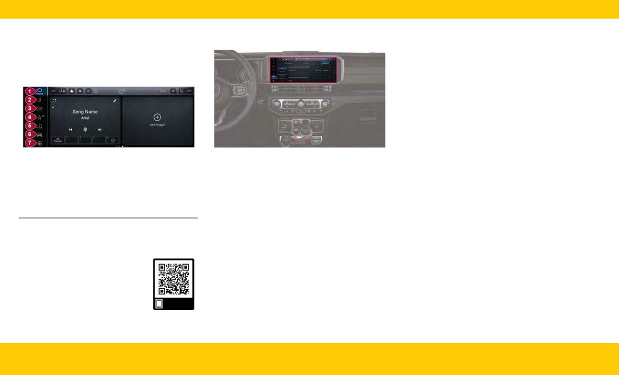
MULTIMEDIA & PHONE
UCONNECT SETTINGS
• My Profile - Customize features such as “Voice
Options”, “Notification Pop-ups”, and much
CONNECTIVITY
more!
Display - Customize features such as your dis-
•
UCONNECT SYSTEM
play brightness, or even allow navigation
instructions to appear on your instrument clus-
ter display!
• Safety/Driving Assistance - Would you like to
be able to customize your Forward Collision
Warning features? Within the Safety/Driving
Assistance setting, you can customize both the
warning and sensitivity for your Forward Colli-
sion Warning detection.
Uconnect 5/5 NAV Display
Uconnect 5/5 NAV Uconnect Settings
• Phone/Bluetooth® - Do you have your phone
paired to your Uconnect system yet? Press the
1 - Home Button
5 - Phone Button
Do you want to change the theme of your radio?
Phone/Bluetooth® button to begin the phone
2 - Radio/Media Button
6 - Vehicle Button
Or what about setting text message pop-up
pairing process.
3 - Comfort Button
7 - Apps Button
notifications?
Camera - Pressing the Camera button on the
•
4 - Navigation Button
These settings are all customizable, and can be
touchscreen will display settings related to the
(If Equipped)
adjusted to your needs with a press of your
vehicle’s cameras. A couple of these settings
fingertip.
are “ParkView Backup Camera Delay” and “For-
NOTE:
Press the Vehicle button, then press the Settings
ward Facing Camera Guidelines”.
Uconnect screen images may not reflect the
button toward the top of your touchscreen to get
• Seats & Comfort - The Uconnect system
exact software in your vehicle.
started with customizing your settings.
allows you to adjust your comfort levels for
Use this QR code to access your
your heated seats, heated steering wheel, and
NOTE:
digital experience.
even ventilated seats!
Depending on the vehicle’s options, feature set-
tings may vary.
• Key Off Options - The Uconnect system gives
you the option to customize what your vehicle
Scan me
does when it shuts down. One option is adjust-
ing how long your headlights stay on after you
turn your vehicle off.
10
INTERIOR
• Audio - Did you know you can customize your
4. Select “Add Device”.
APPLE CARPLAY®
vehicle’s audio? Press the Audio button to
5. Follow the prompts on your phone and on the
To use Apple CarPlay®, follow these steps:
begin tuning your vehicle’s audio to your liking.
touchscreen.
1. Ensure your iPhone® is unlocked for the very
Use this QR code to access your
first connection, then ensure Siri is enabled in
digital experience.
“Settings”.
2. Connect your iPhone® to one of the media
USB ports in your vehicle, or pair your iPhone®
Scan me
with the system. You have no need to plug
your device in if it is paired with the system.
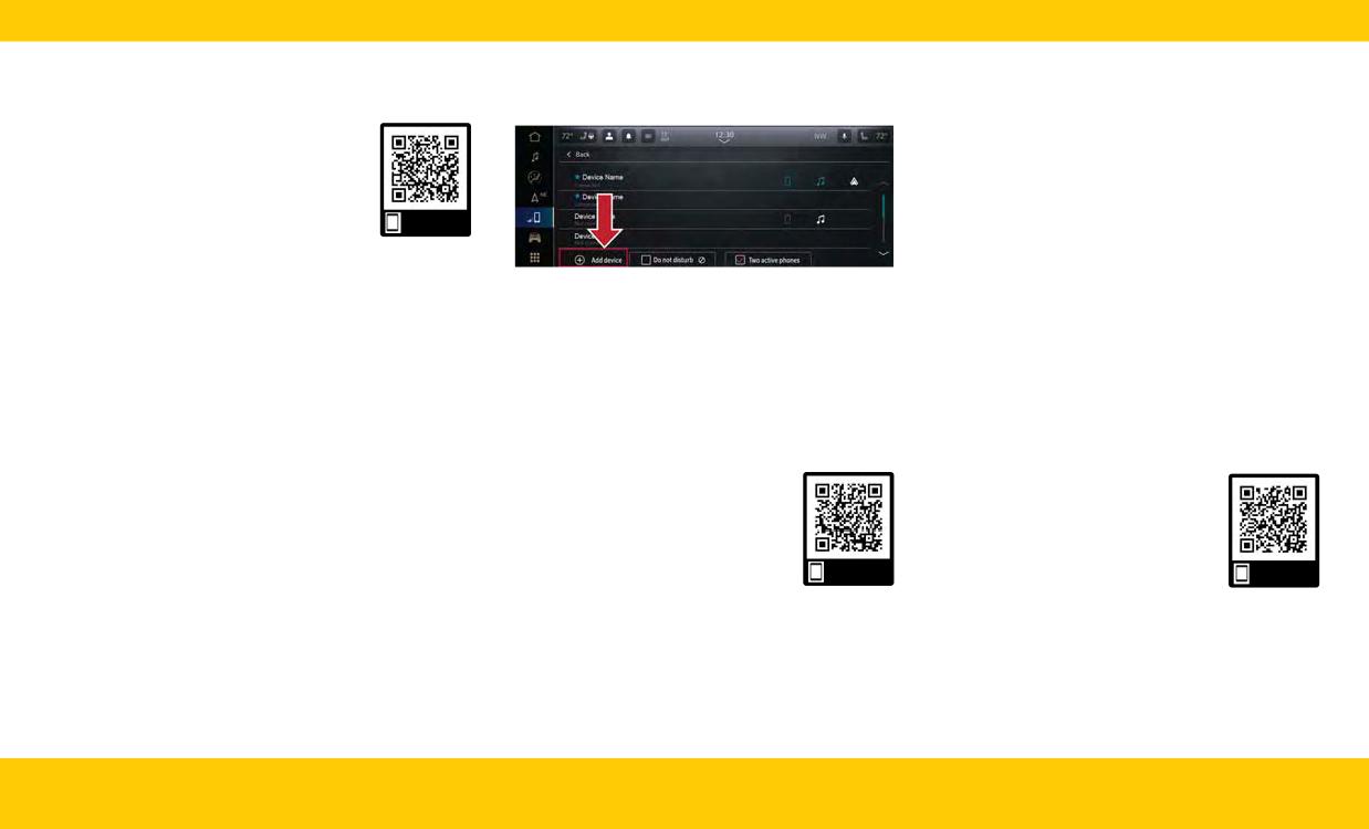
PAIR/DELETE A DEVICE
3. Once the device is connected and recognized,
Uconnect 5/5 NAV Pairing A Phone
the Phone icon on the menu bar changes to
Did you know pairing your smartphone with your
Follow these steps to remove your smartphone:
the Apple CarPlay® icon.
vehicle is quick and easy?
1. Press the Device Manager button on the
Pairing your smartphone with your vehicle will
NOTE:
touchscreen.
open even more possibilities for your driving
To use Apple CarPlay®, make sure cellular data is
convenience, such as playing music from your
2. Press the Settings gear icon next to the phone
turned on and you are in an area with cellular
phone or answering calls through your Uconnect
or device you wish to remove.
coverage. Your data and cellular coverage is
system.
3. Press “Delete Device”. The device should be
shown on the left side of the touchscreen within
1. Make sure Bluetooth® is enabled on your
removed.
Apple CarPlay®. Data plan rates may apply.
mobile phone.
Use this QR code to access your
Use this QR code to access your
2. With the vehicle in the ACC or ON/RUN posi-
digital experience.
digital experience.
tion, press the Phone button on the vehicle’s
touchscreen menu bar.
3. Press “Device Manager”.
Scan me
Scan me
INTERIOR
11
ANDROID AUTO™
UCONNECT VOICE RECOGNITION
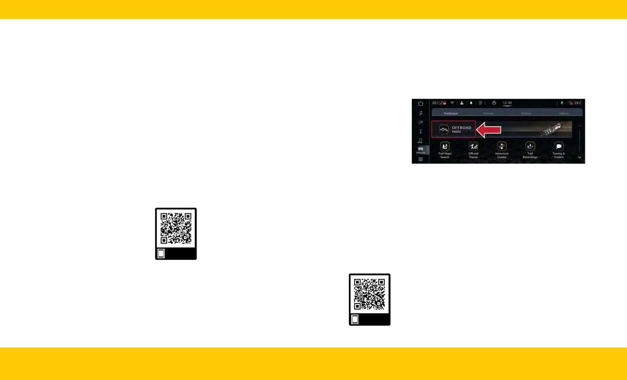
OFF-ROAD PAGES
To use Android Auto™, follow these steps:
Off-Road Pages is an application that provides
Introduction
1. Download the Android Auto™ app from the
vehicle status information while operation in off-
Did you know your vehicle is capable of voice
road conditions. It supplies information relating
Google Play store.
commands? This feature is called Voice Recogni-
to the status of the drivetrain, transfer case,
2. Connect your phone to one of the media USB
tion (VR).
coolant/oil gauges, pitch and roll of the vehicle
ports in your vehicle, or pair your phone with
Start using Uconnect VR with these helpful quick
and access to the trailcam system.
the system. You have no need to plug your
tips. They provide the key voice commands and
device in if it is paired with the system.
tips you need to know to control your vehicle’s
3. Once the device is connected and recognized,
VR system.
the Phone icon on the menu bar changes to
the Android Auto™ icon.
Basic Voice Commands
NOTE:
The following basic voice commands can be
To use Android Auto™, make sure you are in an
given at any point while using your Uconnect
area with cellular coverage. Android Auto™ may
system.
Uconnect 5/5 NAV Off-Road Pages
use cellular data, and your cellular coverage is
Push the VR button or, for the Uconnect
To access the Off-Road Pages:
shown in the upper right corner of the touch-
5/5 NAV, say the vehicle’s “Wake Up” word, “Hey,
screen. Data plan rates may apply.
Uconnect”. After the beep, say:
1. Press the Apps button on the touchscreen.
Use this QR code to access your
2. Press “Off-Road Pages”.
• “Cancel” to stop a current voice session.
digital experience.
3. Press the desired button on the touchscreen
• “Help” to hear a list of suggested Voice
Commands.
to access that specific option within the Off-
Road Pages.
• “Repeat” to listen to the system prompts again.
Scan me
Notice the visual cues that inform you of your VR
system’s status on your Uconnect system.
Use this QR code to access your
digital experience.
Scan me
12
INTERIOR
CHARGING & OUTLETS
• Power outlets labeled with a key symbol are
CAUTION!
powered when the ignition is in the ON/RUN
position.
• Many accessories that can be plugged in draw
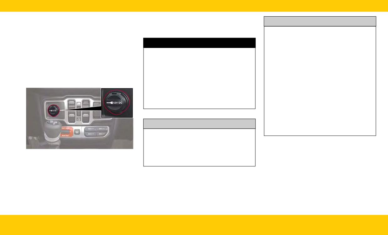
ELECTRICAL POWER OUTLETS
power from the vehicle's battery, even when
There is a 12 Volt (13 A) auxiliary power outlet
not in use (i.e., cellular phones, etc.). Eventu-
WARNING!
that can provide power for accessories designed
ally, if plugged in long enough, the vehicle's
for use with the standard power outlet adapters.
battery will discharge sufficiently to degrade
To avoid serious injury or death:
The front power outlet is located in the center of
battery life and/or prevent the engine from
• Only devices designed for use in this type of
the instrument panel below the climate controls,
outlet should be inserted into any 12 Volt
starting.
and is powered from the ignition switch. Power is
outlet.
• Accessories that draw higher power (i.e., cool-
available when the ignition switch is in the ACC
ers, vacuum cleaners, lights, etc.), will dis-
• Do not touch with wet hands.
or ON/RUN position.
charge the battery even more quickly. Only
• Close the lid when not in use and while driv-
use these intermittently and with greater
ing the vehicle.
caution.
• If this outlet is mishandled, it may cause an
electric shock and failure.
• After the use of high power draw accessories,
or long periods of the vehicle not being
started (with accessories still plugged in), the
vehicle must be driven a sufficient length of
CAUTION!
time to allow the generator to recharge the
vehicle's battery.
• Power outlets are designed for accessory
plugs only. Do not insert any other object in
the power outlets as this will damage the out-
let and blow the fuse. Improper use of the
Front Power Outlet
power outlet can cause damage not covered
NOTE:
by your New Vehicle Limited Warranty.
(Continued)
• Do not connect any of your devices that have a
power rating higher than 160 W to the outlet.
Do not use power adapters that do not fit the
outlet as this may damage it.
INTERIOR
13
POWER INVERTERS -
video game consoles exceed this limit, as will
NOTE:
most power tools. The indicator light on the
400 W is the maximum for the inverter, not each
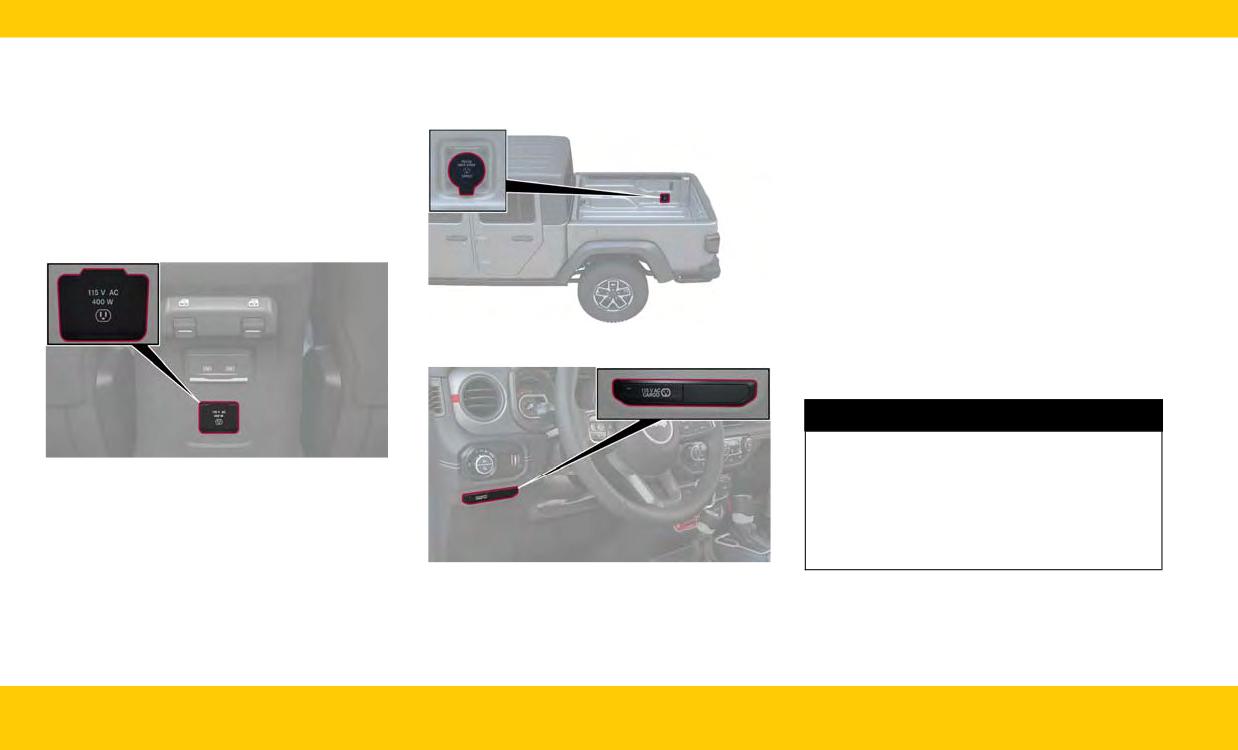
IF EQUIPPED
power inverter switch will be illuminated when
outlet. If two outlets are in use, 400 W is shared
There is a 115 V (400 W) maximum inverter out-
the inverter is turned on.
among the devices plugged in.
let located on the back of the center console to
The power inverter is designed with built-in over-
convert Direct Current (DC) to Alternating Cur-
load protection. If the power rating of 400 W is
rent (AC).
exceeded, the power inverter automatically shuts
This outlet can power cellular phones, electronics
down. Once the electrical device has been
and other low power devices requiring power up
removed from the outlet, the inverter should
to 400 W. Certain video game consoles exceed
automatically reset.
this power limit, as will most power tools.
NOTE:
• The Power Inverter will only turn on if the igni-
tion is in the ACC or ON/RUN position.
• Due to built-in overload protection, the power
Exterior Truck Bed Power Inverter (If Equipped)
inverter will turn off if the power rating is
exceeded.
WARNING!
To avoid serious injury or death:
Power Inverter
•
Do not insert any objects into the receptacles.
• Do not touch with wet hands.
There may also be a second 115 V (400 W) maxi-
mum exterior power inverter located on the rear
• Close the lid when not in use.
right side of the truck bed near the tailgate. This
• If this outlet is mishandled, it may cause an
inverter can be turned on by the Instrument
electric shock and failure.
Panel Power Inverter switch located to the left of
Power Inverter Switch (If Equipped)
the steering wheel. This inverter can power cellu-
lar phones, electronics and other low power
devices requiring power up to 400 W. Certain
14
INTERIOR
USB/AUX CONTROL
Plugging in a mobile device to a USB port below
the Uconnect screen may activate the Android
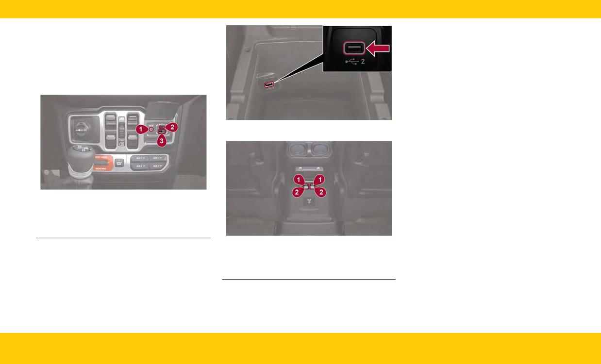
Your vehicle may be equipped with two USB
Auto™ or Apple CarPlay® features.
ports and one AUX port located on the instru-
To disable Android Auto™ or Apple CarPlay®,
ment panel below the climate controls. Your
navigate to “Device Manager” in the
vehicle may also be equipped with USB ports
“Phone/Bluetooth®” section of your Uconnect
located inside the center console or behind the
settings. For further information, refer to
center stack, above the power inverter.
“Android Auto™” or “Apple CarPlay®” in
“Multimedia” in your Owner’s Manual.
For additional information please visit
UconnectPhone.com.
Center Console Charge-Only USB Port
Front USB/AUX Ports
1 - AUX Port
2 - USB Type C
3 - USB Type A
Rear Charge-Only USB Ports
1 - Charge-Only USB Type C
2 - Charge-Only USB Type A
INTERIOR
15
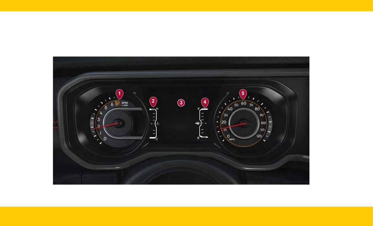
INSTRUMENT CLUSTER
GETTING TO KNOW YOUR INSTRUMENT CLUSTER
NOTE:
Depending on your vehicle trim, your instrument cluster display may vary.
16
INTERIOR
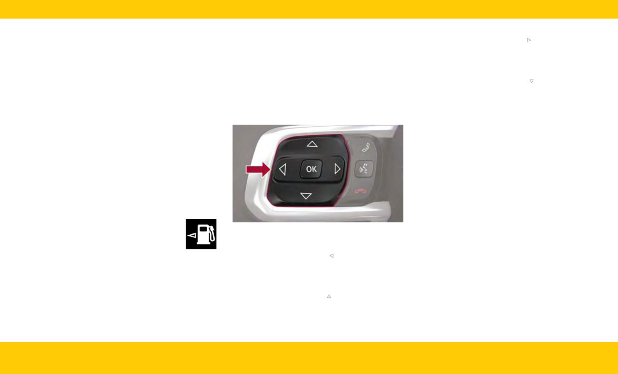
1. Tachometer
INSTRUMENT CLUSTER
• Right Arrow Button
○ Indicates the engine speed in revolutions
Push and release the right
arrow button to
DISPLAY LOCATION AND
per minute (RPM x 100).
access the information screens or submenu
CONTROLS
screens of a main menu item.
2. Temperature Gauge
The instrument cluster display is located in the
○ The temperature gauge shows engine cool-
• Down Arrow Button
center of the instrument cluster.
ant temperature. Any reading within the
Push and release the down
arrow button to
The system allows the driver to select informa-
scroll downward through the Main Menu items.
normal range indicates that the engine is
tion by pushing the instrument cluster display
operating satisfactorily.
• OK Button
control buttons located on the left side of the
3. Instrument Cluster Display
Push the OK button to access/select the infor-
steering wheel.
mation screens or submenu screens of a Main
○ When the appropriate conditions exist, this
Menu item. Push and hold the OK arrow button
display shows the instrument cluster dis-
for two seconds to reset displayed/selected
play messages.
features that can be reset.
○ The display always shows one of the main
menu items after ignition is placed on.
WARNING LIGHTS AND
4. Fuel Gauge
MESSAGES
○ The gauge shows the level of fuel in the fuel
These symbols are Warning/Indicator lights that
tank when the Keyless Push Button Ignition
illuminate to signify various conditions with your
is in the ON/RUN position.
vehicle, ranging from potentially critical faults to
○ The fuel pump symbol points to
merely informing you that a feature has been
the side of the vehicle where the
Instrument Cluster Display Control Buttons
engaged. Warning and Indicator Lights are differ-
fuel door is located.
ent based upon equipment options and current
• Left Arrow Button
5. Speedometer
vehicle status. Some telltales are optional and
Push and release the left
arrow button to
may not appear.
○ Indicates vehicle speed.
access the information screens or submenu
screens of a main menu item.
NOTE:
• Up Arrow Button
For more information about warning lights, indi-
cators and messages (including “service trans-
Push and release the up
arrow button to
mission”) please see your owners manual.
scroll upward through the Main Menu items.
INTERIOR
17
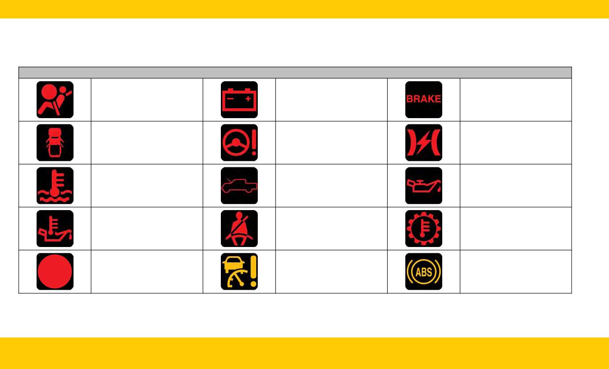
Warning & Indicator Lights
If any of the Warning Lights illuminate in your cluster, a condition may need to be corrected or your vehicle may require service. In these situations it is rec-
ommended that you contact your local authorized dealer to schedule service.
The Indicator Lights illuminate in your cluster to indicate a feature is active.
Warning Lights
Air Bag
Battery Charge
Brake
Electric Power Steering (EPS)
Electronic Throttle Control
Door Open
Fault
(EPS) Fault
Engine Coolant Temperature
Hood Open
Oil Pressure
Oil Temperature
Seat Belt Reminder
Transmission Temperature
Adaptive Cruise Control
Anti-Lock Brake System
Vehicle Security
(ACC) Fault
(ABS)
18
INTERIOR
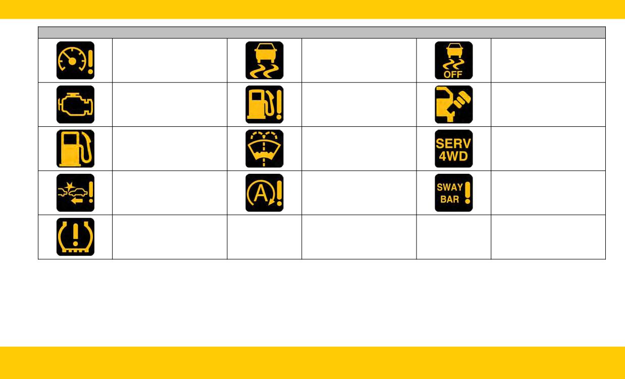
Warning Lights
Electronic Stability Control
Electronic Stability Control
Cruise Control Fault
(ESC) Active Warning
(ESC) OFF Warning
Engine Check/Malfunction
Fuel Level Sensor Failure
Loose Fuel Filler Cap
Low Fuel
Low Washer Fluid
Service 4WD
Service Forward Collision
Service Stop/Start System
Sway Bar Fault
Warning (FCW)
Tire Pressure Monitoring
System (TPMS)
INTERIOR
19
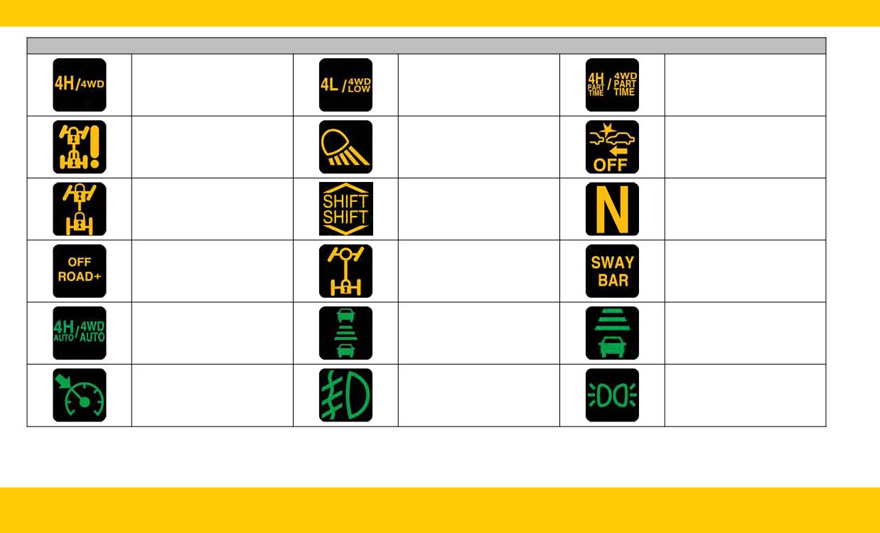
Indicator Lights
4WD
4WD Low
4WD Part Time
Forward Collision Warning
Axle Locker Fault
Cargo Light
(FCW) Off
Front And Rear Axle Lock
Gear Shift
Neutral
Off Road+
Rear Axle Lock
Sway Bar
Adaptive Cruise Control
Adaptive Cruise Control
4WD AUTO
(ACC) Set With No Target
(ACC) Set With Target
Detected
Cruise Control Set
Front Fog Lights
Parking/Headlights On
20
INTERIOR
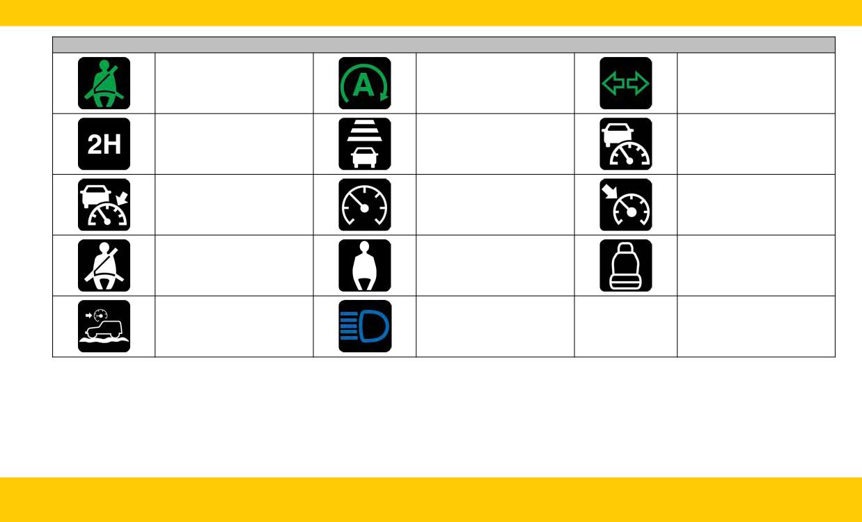
Indicator Lights
Rear Seat Belt Reminder
Stop/Start Active
Turn Signal
Adaptive Cruise Control
Adaptive Cruise Control
2WD High
(ACC) Ready
(ACC) Ready
Adaptive Cruise Control
Cruise Control Ready
Cruise Control Set
(ACC) Set
Rear Seat Belt Reminder
Rear Seat Belt Reminder
Rear Seat Unoccupied
Selec-Speed Control
High Beam
INTERIOR
21
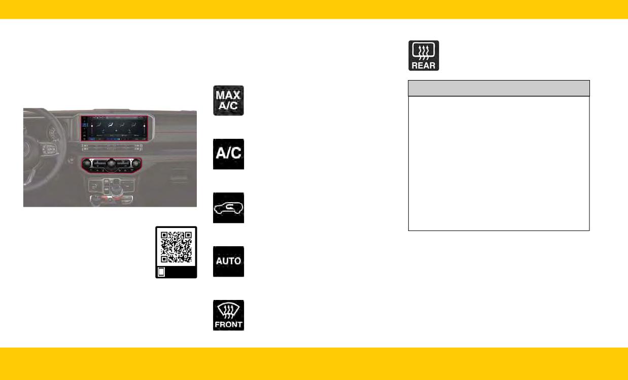
INTERIOR COMFORT
AUTOMATIC CLIMATE
Rear Defrost Button
CONTROL DESCRIPTIONS AND
Push the button to turn on the rear win-
SETTINGS
dow defroster and heated mirrors.
FUNCTIONS
CLIMATE CONTROLS
MAX A/C Button
The Climate Control system allows you to regu-
late the temperature, air flow, and direction of air
Press the button on the touchscreen to
CAUTION!
set the system to maximum Air Condi-
circulating throughout the vehicle.
tioning (A/C).
Failure to follow these cautions can cause dam-
age to the heating elements:
A/C Button
• Use care when washing the inside of the rear
window. Do not use abrasive window cleaners
Push the button to engage the Air Con-
on the interior surface of the window. Use a
ditioning (A/C) system.
soft cloth and a mild washing solution, wiping
parallel to the heating elements. Labels can be
peeled off after soaking with warm water.
Recirculation Button
• Do not use scrapers, sharp instruments, or
Push the button to change the system
abrasive window cleaners on the interior sur-
between Recirculation mode and out-
face of the window.
Uconnect 5/5 NAV Automatic Climate Controls
side air mode.
• Keep all objects a safe distance from the
window.
Use this QR code to access your
Auto Button
digital experience.
Push the button after setting your
desired temperature and the system will
maintain the set temperature.
Scan me
Front Defrost Button
Push the button to change the current
airflow setting to Defrost mode.
22
INTERIOR
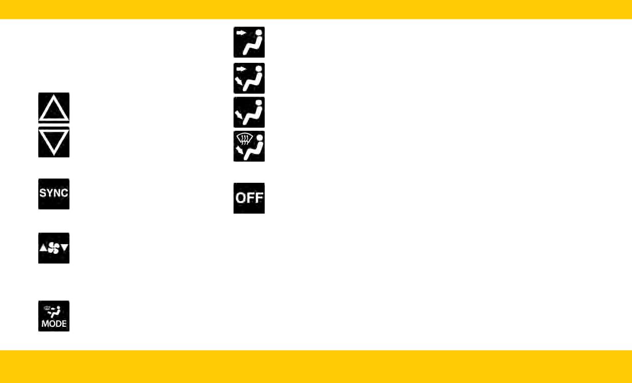
Driver And Passenger Temperature
Panel Mode
NOTE:
There will be no need for you to move the tem-
Controls
perature settings for cold or hot vehicles. The
Push the driver or passenger’s side toggle switch
system automatically adjusts the temperature,
upward or downward, or slide the temperature
Bi-Level Mode
mode, and blower speed to provide comfort as
bar to adjust the driver and passenger tempera-
quickly as possible.
ture settings.
Manual Operation Override
Floor Mode
Your Climate Control system includes manual
override features. The AUTO symbol in the front
ATC display will turn off when the system is in
the manual mode.
Mix Mode
CLIMATE VOICE RECOGNITION
You can adjust your vehicle’s temperature hands-
SYNC Button
free while you’re driving.
Climate Control OFF Button
Press the SYNC button on the touch-
Push the VR button on the steering wheel. After
Press the button to turn the climate
screen to synchronize the driver and
the beep, say one of the following commands:
control system off.
front passenger temperature settings.
• “Set driver temperature to 70 degrees”
“Set passenger temperature to 70 degrees”
•
Blower Control
AUTOMATIC TEMPERATURE
Did you know: Voice Recognition for Climate
Use the small or large blower icon
may only be used to adjust the interior tempera-
CONTROL (ATC)
toggle switches or the blower bar on
ture of your vehicle. Voice Recognition will not
the touchscreen to increase or decrease
Automatic Operation
work to adjust the heated seats or steering
the amount of air forced through the
1. Push the AUTO button on the faceplate or the
wheel.
climate control system.
AUTO button on the touchscreen.
2. Select the desired temperature using the
Mode Control
toggle switches or the touchscreen. The sys-
Select Mode by pressing one of the
tem then achieves and automatically maintains
Mode buttons on the touchscreen, or
that comfort level.
the faceplate, to change the airflow dis-
tribution mode.
INTERIOR
23
FRONT HEATED SEATS -
POWER FRONT SEATS
WARNING!
IF EQUIPPED
ADJUSTMENT - IF EQUIPPED
Do not ride with the seatback reclined so that
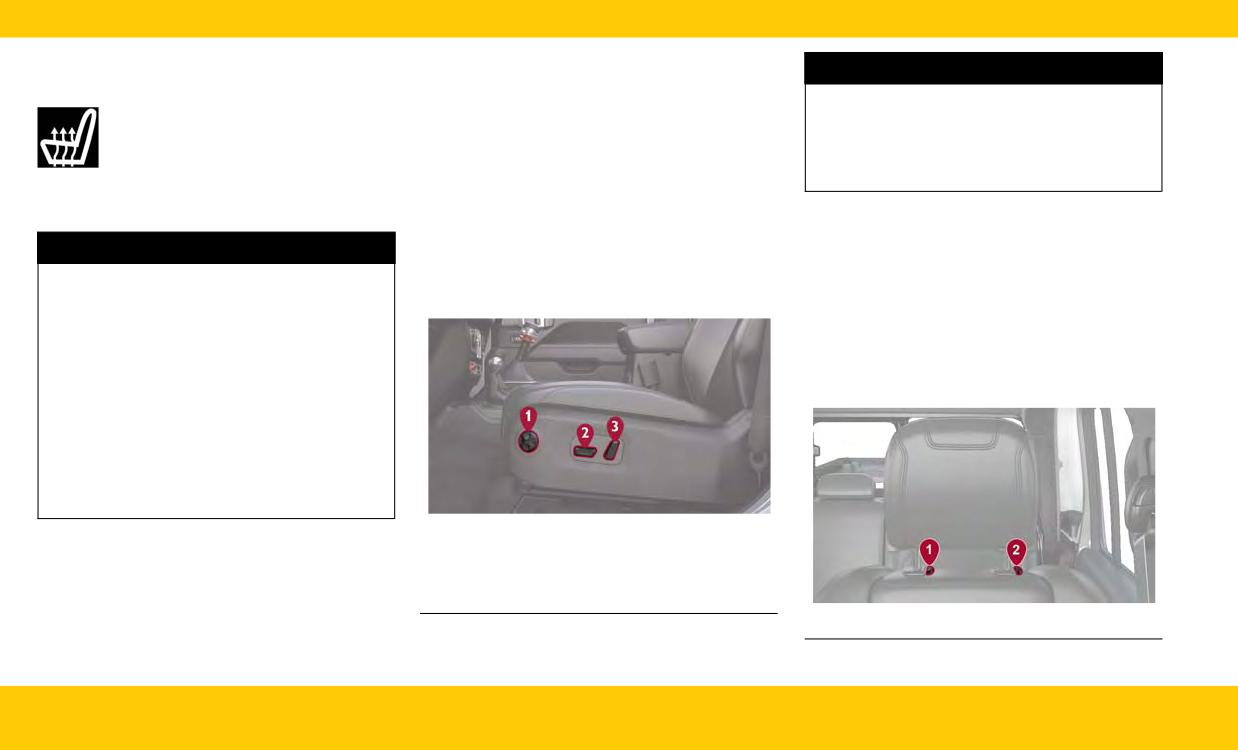
The heated seat control buttons are
The power seat switch and power seat recline
the shoulder belt is no longer resting against
located on the center instrument panel
switch are located on the outboard side of the
your chest. In a collision you could slide under
below the touchscreen and also in the
seat near the floor. Use the power seat switch to
the seat belt, which could result in serious
Climate Control touchscreen menu.
adjust seat height, angle, or forward/rearward
injury or death.
Press the heated seat button to cycle through HI,
position. Use the power seat recline switch to
MED, LO, and off settings.
adjust the angle of the seatback.
Push the power lumbar switch forward to
HEAD RESTRAINTS
WARNING!
increase the lumbar support. Push the switch
Did you know your vehicle is equipped with front
rearward to decrease the lumbar support. Push-
• Persons who are unable to feel pain to the
driver and passenger head restraints that can be
ing upward or downward on the switch will raise
skin because of advanced age, chronic illness,
adjusted two different ways?
and lower the position of the support.
diabetes, spinal cord injury, medication, alco-
Head restraints are designed to reduce the risk of
hol use, exhaustion or other physical condition
injury by restricting head movement in the event
must exercise care when using the seat heater.
of a rear impact. Head restraints should be
It may cause burns even at low temperatures,
adjusted so that the top of the head restraint is
especially if used for long periods of time.
located above the top of your ear.
• Do not place anything on the seat or seatback
that insulates against heat, such as a blanket
or cushion. This may cause the seat heater to
overheat. Sitting in a seat that has been over-
heated could cause serious burns due to the
increased surface temperature of the seat.
Driver Power Seat Switches
1 - Power Lumbar Switch
2 - Power Seat Switch
3 - Power Recline Switch
1 - Removal Button
2 - Adjustment Button
24
INTERIOR
• To raise the head restraint, pull upward on the
and the release button at the base of each post
LIGHTING OPERATION
head restraint.
while pulling the head restraint up.
• To lower the head restraint, push the adjust-
To reinstall the head restraint, put the head
HEADLIGHT SWITCH
ment button, located at the base of the head
restraint posts into the holes and push down-
The headlight switch is located on the left side of
restraint, while pushing downward on the head
ward. Then, adjust it to the appropriate height
the instrument panel and is used to control your
restraint.
using the adjustment button.
lighting.
Rear Head Restraints
NOTE:
The rear seat is equipped with non-adjustable,
Lower the center head restraint to avoid contact
but foldable, outboard head restraints.
with the center console when folding the seat
down.
WARNING!
• Do not drive the vehicle without the rear seat
head restraints installed while passengers are
occupying the rear seat. In a collision, people
riding in this area without the head restraints
installed are more likely to be seriously injured
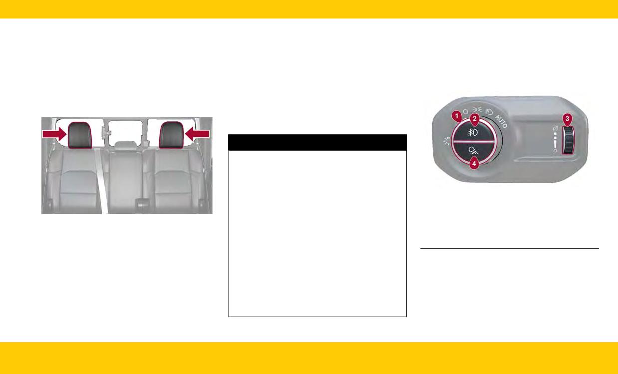
Headlight Switch
or killed.
1 - Rotate Headlight Switch
• A loose head restraint thrown forward in a
Rear Foldable Outboard Head Restraints
2 - Push Front Fog Light
collision or hard stop could cause serious
3 - Dimmer Control
To return the head restraint to its upward posi-
injury or death to occupants of the vehicle.
Always securely stow removed head restraints
4 - Push Bed Light
tion, lift up on the head restraint until it locks into
place.
in a location outside the occupant
compartment.
Rotate the headlight control knob to select one
To raise the center head restraint, lift up on the
of the available positions: O (off), parking lights,
head restraint. To lower the center head restraint,
• ALL the head restraints MUST be reinstalled in
the vehicle to properly protect the occupants.
headlights on, and AUTO headlights.
push the adjustment button, located at the base
of the head restraint, and push down on the head
Follow the preceding reinstallation instruc-
restraint.
tions prior to operating the vehicle or occupy-
ing a seat.
To remove the center head restraint, raise it as far
as it can go. Then, push the adjustment button
INTERIOR
25
AUTOMATIC HIGH BEAMS
NOTE:
The mist feature does not activate the washer
Did you know your vehicle can automatically
pump; therefore, no washer fluid will be sprayed
switch from high beams to low beams until an
on the windshield. The washer function must be
approaching vehicle is out of view?
used in order to spray the windshield with
The Automatic High Beam Headlight Control can
washer fluid.
be turned on or off by selecting “ON” under
“Auto High Beam” within your Uconnect Set-
WARNING!
tings, as well as turning the headlight switch to
the AUTO position and placing the multifunction
Sudden loss of visibility through the windshield
lever in the high beam position.
could lead to a collision. You might not see
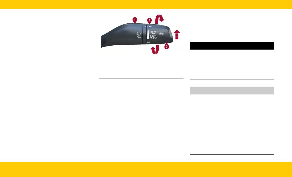
Windshield Wiper/Washer Lever
other vehicles or other obstacles. To avoid sud-
AUTOMATIC HEADLIGHTS
1 - Pull For Windshield Washer
den icing of the windshield during freezing
With the engine running, make sure your head-
2 - Rotate For Wiper Operation
weather, warm the windshield with the defroster
light control knob is in the AUTO position; your
3 - Push Up For Mist
before and during windshield washer use.
vehicle will detect how bright it is outside and
turn the headlights on/off as necessary.
WINDSHIELD WIPER
OPERATION
CAUTION!
WINDSHIELD WIPERS &
Front Wipers
•
Always remove any buildup of snow that pre-
WASHERS
vents the windshield wiper blades from
Rotate the end of the lever upward to the first
detent past the intermittent settings for low-
returning to the parked position. If the wind-
The windshield wiper/washer controls are
speed wiper operation.
shield wiper switch is turned off, and the
located on the windshield wiper/washer lever on
blades cannot return to the parked position,
the right side of the steering column. The front
Rotate the end of the lever upward to the second
damage to the wiper motor may occur.
wipers are operated by rotating a switch, located
detent past the intermittent settings for high-
on the end of the lever.
speed wiper operation.
• In cold weather, always turn off the wiper
switch and allow the wipers to return to the
Windshield Washers
park position before turning off the engine. If
To use the washer, pull the windshield wiper lever
the wiper switch is left on and the wipers
toward the steering wheel and hold.
freeze to the windshield, damage to the wiper
Mist
motor may occur when the vehicle is
Push the lever upward to the MIST position and
restarted.
release for a single wiping cycle.
26
INTERIOR
CRUISE CONTROL
WARNING!
WARNING!
SYSTEMS
Your complete attention is always required
○ Will bring the vehicle to a complete stop
while driving to maintain safe control of your
while following a vehicle ahead and hold
Your vehicle may be equipped with the Cruise
vehicle. Failure to follow these warnings can
the vehicle for two seconds in the stop
Control system, or the Adaptive Cruise Control
result in a collision and death or serious per-
position. If the vehicle ahead does not start
(ACC) system:
sonal injury.
moving within two seconds the ACC sys-
• Cruise Control will keep your vehicle at a con-
tem will display a message that the system
• The ACC system:
stant preset speed.
will release the brakes and that the brakes
○ Does not react to pedestrians, oncoming
• Adaptive Cruise Control (ACC) will adjust the
vehicles, and stationary objects (e.g., a
must be applied manually. An audible
vehicle speed up to the preset speed to main-
stopped vehicle in a traffic jam or a dis-
chime will sound when the brakes are
tain a distance with the vehicle ahead.
abled vehicle).
released.
○ Cannot take street, traffic, and weather
• You should not utilize the ACC system:
NOTE:
conditions into account, and may be lim-
○ When driving in fog, heavy rain, heavy
In vehicles equipped with ACC, if ACC is not
ited upon adverse sight distance condi-
snow, sleet, heavy traffic, and complex
enabled, Fixed Speed Cruise Control will not
tions.
driving situations (i.e., in highway construc-
detect vehicles directly ahead of you. Only one
○ Does not always fully recognize complex
tion zones).
Cruise Control feature can operate at a time.
driving conditions, which can result in
○ When entering a turn lane or highway off-
wrong or missing distance warnings.
ramp; when driving on roads that are wind-
ADAPTIVE CRUISE CONTROL
○ On vehicles with an automatic transmis-
ing, icy, snow-covered, slippery, or have
(ACC)
sion, will bring the vehicle to a complete
steep uphill or downhill slopes.
stop while following a vehicle ahead and
○ When towing a trailer up or down steep
WARNING!
hold the vehicle for two seconds in the
slopes.
stop position. If the vehicle ahead does not
○ When circumstances do not allow safe
• Adaptive Cruise Control (ACC) is a conve-
start moving within two seconds, the ACC
driving at a constant speed.
nience system. It is not a substitute for active
system will display a message that the sys-
driver involvement. It is always the driver’s
tem will release the brakes and that the
responsibility to be attentive of road, traffic,
brakes must be applied manually. An
and weather conditions, vehicle speed, dis-
audible chime will sound when the brakes
tance to the vehicle ahead and, most impor-
are released.
tantly, brake operation to ensure safe opera-
(Continued)
tion of the vehicle under all road conditions.
(Continued)
INTERIOR
27
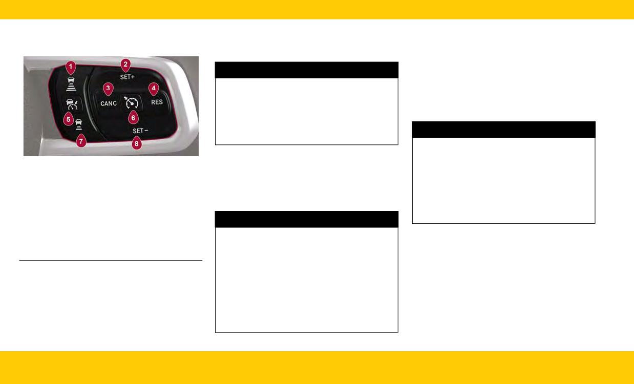
The buttons on the right side of the steering
• To Activate/Deactivate
• To Deactivate
wheel operate the Cruise Control and ACC
○ Push and release the Adaptive Cruise Con-
○ To turn the system off, push and release the
systems.
trol (ACC) on/off button.
Adaptive Cruise Control (ACC) on/off but-
ton again, or by placing your vehicle’s igni-
tion in the OFF position.
WARNING!
• To Resume Speed
Leaving the Adaptive Cruise Control (ACC) sys-
○ If ACC was canceled, and there is a set
tem on when not in use is dangerous. You could
speed in memory, push the RES (resume)
accidentally set the system or cause it to go
button.
faster than you want. You could lose control
and have a collision. Always leave the system
WARNING!
off when you are not using it.
The Resume function should only be used if
• To Set A Desired ACC Speed
traffic and road conditions permit. Resuming a
Adaptive Cruise Control Buttons
○ When the vehicle reaches the speed
set speed that is too high or too low for prevail-
1 - Distance Setting Increase
desired, push the SET (+) button or the SET
ing traffic and road conditions could cause the
2 - SET (+)/Accel
(-) button and release. The instrument clus-
vehicle to accelerate or decelerate too sharply
ter display will show the set speed.
for safe operation. Failure to follow these warn-
3 - CANC/Cancel
ings can result in a collision and death or seri-
4 - RES/Resume
ous personal injury.
5 - ACC On/Off
WARNING!
6 - Fixed Speed Cruise Control On/Off
In Fixed Speed Cruise Control mode, the sys-
• To Vary The Speed Setting
7 - Distance Setting Decrease
tem will not react to vehicles ahead. In addition,
○ After setting a speed, you can increase the
8 - SET (-)/Decel
the proximity warning does not activate and no
set speed by pushing the SET (+) button, or
alarm will sound even if you are too close to the
decrease speed by pushing the SET (-)
vehicle ahead since neither the presence of the
button.
vehicle ahead nor the vehicle-to-vehicle dis-
• Setting The Following Distance In ACC
tance is detected. Be sure to maintain a safe
○ To increase the distance setting, push the
distance between your vehicle and the vehicle
Distance Setting Increase button and
ahead. Always be aware which mode is
release. Each time the button is pushed, the
selected.
distance setting increases by one bar
(longer).
28
INTERIOR
○ To decrease the distance setting, push the
• TO ERASE ALL SET CHANNELS: Push and hold
To erase all set channels
Distance Setting Decrease button and
the two outside HomeLink® buttons for 20 sec-
1. Place the ignition switch in the ON/RUN
release. Each time the button is pushed, the
onds until the indicator flashes above the
position.
distance setting decreases by one bar
buttons.
2. Push and hold the two outside HomeLink®
(shorter).
• ROLLING OR NON-ROLLING? Check your
buttons (I and III) for up to 20 seconds, or
Use this QR code to access your
garage door opener motor in your garage for a
until the HomeLink® indicator light flashes.
digital experience.
“LEARN” or “TRAIN” button by the hanging
antenna. If you have one of these, you have a
WARNING!
Rolling Code garage door opener.
1. While the car is ON, hold the handheld garage
• Your motorized door or gate will open and
Scan me
door transmitter 1-3 inches from the
close while you are programming the univer-
HomeLink® button you want to program in the
sal transmitter. Do not program the transmit-
vehicle.
ter if people or pets are in the path of the
GARAGE DOOR OPENER
door or gate.
2. Push and hold both the HomeLink® button
(HOMELINK®)
being programmed and the button on the
• Do not run your vehicle in a closed garage or
garage door transmitter.
confined area while programming the trans-
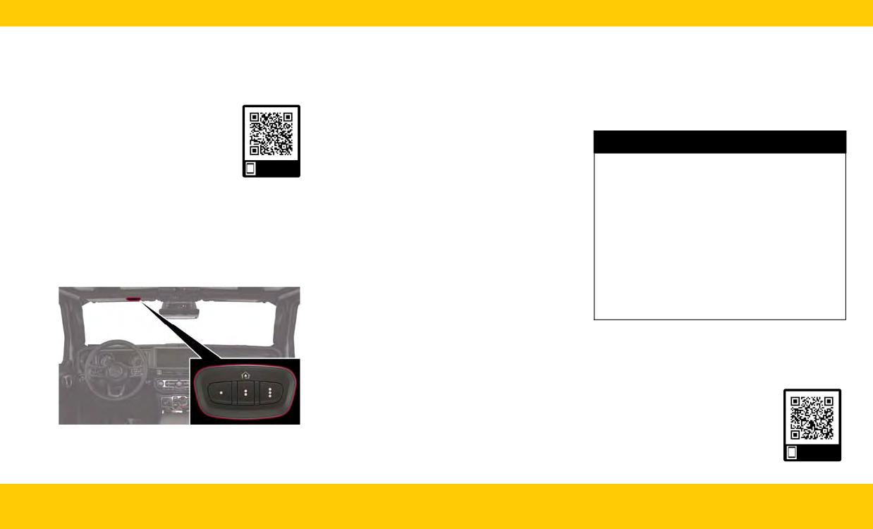
The HomeLink® buttons are located on the sun
mitter. Exhaust gas from your vehicle contains
visor and contain three optional HomeLink®
3. For Non-Rolling Code garage door openers,
carbon monoxide (CO) which is odorless and
channels.
watch for the indicator light to stay
colorless. Carbon monoxide is poisonous
illuminated.
when inhaled and can cause you and others to
For Rolling Code garage door openers, watch
be severely injured or killed.
for the indicator light to go from a slow blink
to blinking rapidly.
NOTE:
4. For Rolling Code garage door openers only,
If the programming was successful, your garage
firmly push and release the “LEARN” or
door should open and close with your chosen
“TRAIN” button on your garage door opener
HomeLink® button.
motor in your garage, then push the
Use this QR code to access your
HomeLink® button in your vehicle three times
digital experience.
(holding the button for two seconds each
time).
HomeLink® Buttons
Scan me
INTERIOR
29
TROUBLESHOOTING TIPS
WARNING!
WARNING!
If you are having trouble programming
garage door opener models manufactured
• Drivers must be careful when backing up even
HomeLink®, here are some of the most common
after 1982. Do not use a garage door opener
when using ParkSense. Always check carefully
solutions:
without these safety features.
behind your vehicle, look behind you, and be
• Replace the battery in the garage door opener
sure to check for pedestrians, animals, other
hand-held transmitter.
vehicles, obstructions, and blind spots before
• Push the LEARN button on the garage door
PARKING ASSISTANCE
backing up. You are responsible for safety and
opener to complete the training for a rolling
must continue to pay attention to your sur-
code.
roundings. Failure to do so can result in seri-
PARKSENSE REAR PARK ASSIST
ous injury or death.
• Did you unplug the device for programming
SYSTEM - IF EQUIPPED
and remember to plug it back in?
• Before using ParkSense, it is strongly recom-
If you have any problems, or require additional
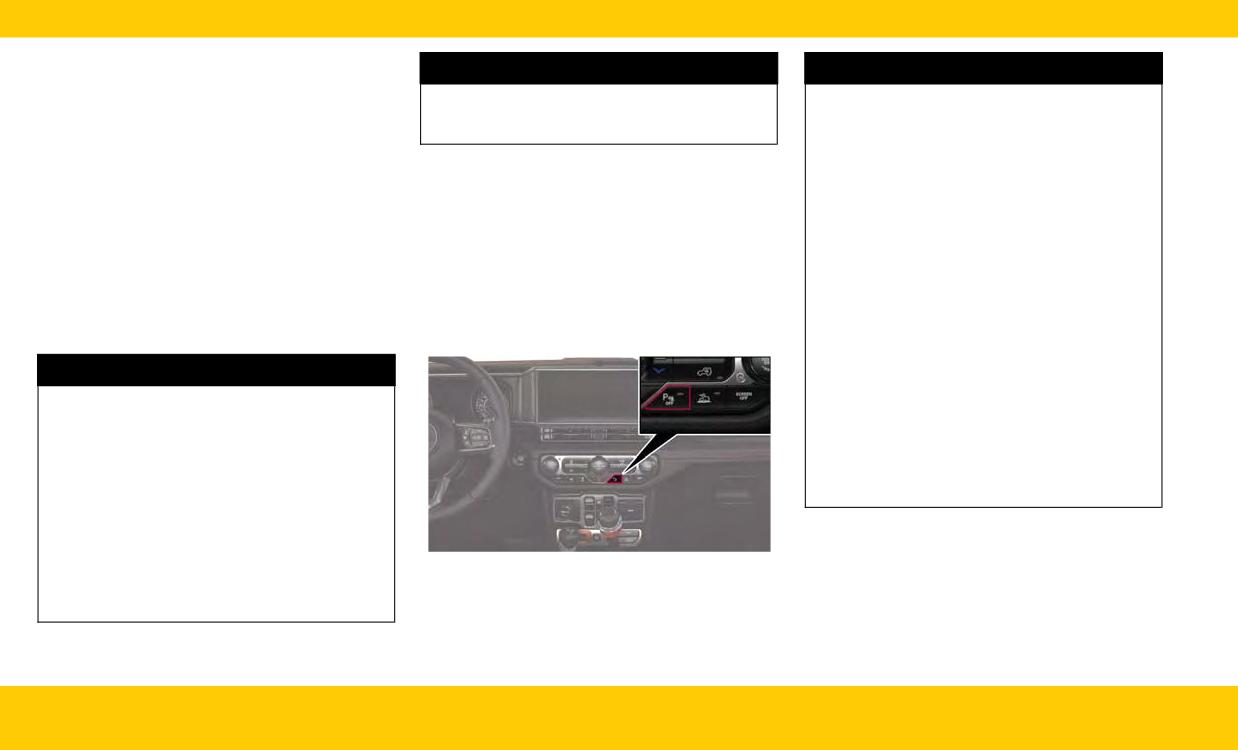
Did you know you can enable and disable the
mended that the ball mount and hitch ball
assistance, please call toll-free 1-800-355-3515 or
ParkSense system using the ParkSense switch,
assembly be disconnected from the vehicle
visit HomeLink.com.
located in front of the center console, below the
when the vehicle is not used for towing. Fail-
climate controls?
ure to do so can result in injury or damage to
vehicles or obstacles because the hitch ball
WARNING!
will be much closer to the obstacle than the
• Vehicle exhaust contains carbon monoxide, a
rear fascia/bumper when the vehicle sounds
dangerous gas. Do not run your vehicle in the
the continuous tone. Also, the sensors could
garage while programming the transmitter.
detect the ball mount and hitch ball assembly,
Exhaust gas can cause serious injury or death.
depending on its size and shape, giving a false
indication that an obstacle is behind the
• Your motorized door or gate will open and
close while you are programming the univer-
vehicle.
sal transmitter. Do not program the transmit-
ter if people, pets or other objects are in the
path of the door or gate. Only use this trans-
mitter with a garage door opener that has a
ParkSense Switch
“stop and reverse” feature as required by Fed-
eral safety standards. This includes most
(Continued)
30
INTERIOR
Use this QR code to access your
CAUTION!
digital experience.
• ParkSense is only a parking aid and it is
unable to recognize every obstacle, including
small obstacles. Parking curbs might be tem-
Scan me
porarily detected or not detected at all.
Obstacles located above or below the sensors
will not be detected when they are in close
AXLE LOCK (TRU-LOK) REAR
proximity.
ONLY - IF EQUIPPED
• The vehicle must be driven slowly when using
The rear axle may be locked in 4H if the proper
ParkSense in order to be able to stop in time
conditions are met.
when an obstacle is detected. It is recom-
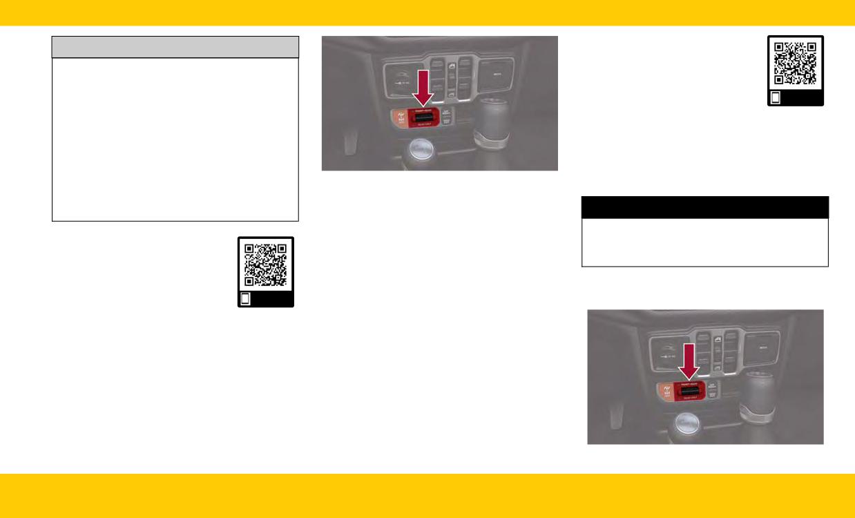
Axle Lock Switch Panel
mended that the driver looks over his/her
This feature will only activate when the following
shoulder when using ParkSense.
WARNING!
conditions are met:
• Ignition in RUN position, vehicle in 4L.
This mode is intended for off-highway or off-
Use this QR code to access your
• Vehicle speed should be 10 mph (16 km/h) or
road use only and should not be used on any
digital experience.
less.
public roadways.
• Both right and left wheels on axle are at the
same speed.
The AXLE LOCK switch is located on the instru-
Scan me
To activate the system, push the AXLE LOCK
ment panel (to the right of the steering column).
switch down to lock the rear axle only, push the
switch up to lock the front axle and rear axle.
OFFROAD FEATURES
When the rear axle is locked, pushing the bottom
of switch again will lock or unlock the front axle.
AXLE LOCK (TRU-LOK) FRONT
To unlock the axles, push the AXLE LOCK OFF
button.
AND REAR - IF EQUIPPED
Axle Lock will disengage if the vehicle is taken
The AXLE LOCK switch is located on the instru-
out of 4L, or the ignition switch is turned to the
ment panel (to the right of the steering column).
OFF position. The Axle Lock disengages at
speeds above 30 mph (48 km/h), and will auto-
matically re-lock once vehicle speed is less than
10 mph (16 km/h).
Axle Lock Switch Panel
INTERIOR
31
This feature will only activate when the following
ELECTRONIC SWAY BAR
conditions are met:
WARNING!
DISCONNECT - IF EQUIPPED
• Ignition in RUN position, vehicle in 4H.
Ensure the stabilizer/sway bar is reconnected
Your vehicle may be equipped with an electronic
• The vehicle must be in Off Road+ active.
before driving on hard surfaced roads or at
disconnecting stabilizer/sway bar.
speeds above 18 mph (29 km/h); a discon-
• Vehicle must be in ESC “Full Off” mode.
nected stabilizer/sway bar may contribute to
• Vehicle must not be actively in a high wheel
the loss of vehicle control, which could result in
slip or tight cornering condition.
serious injury. Under certain circumstances, the
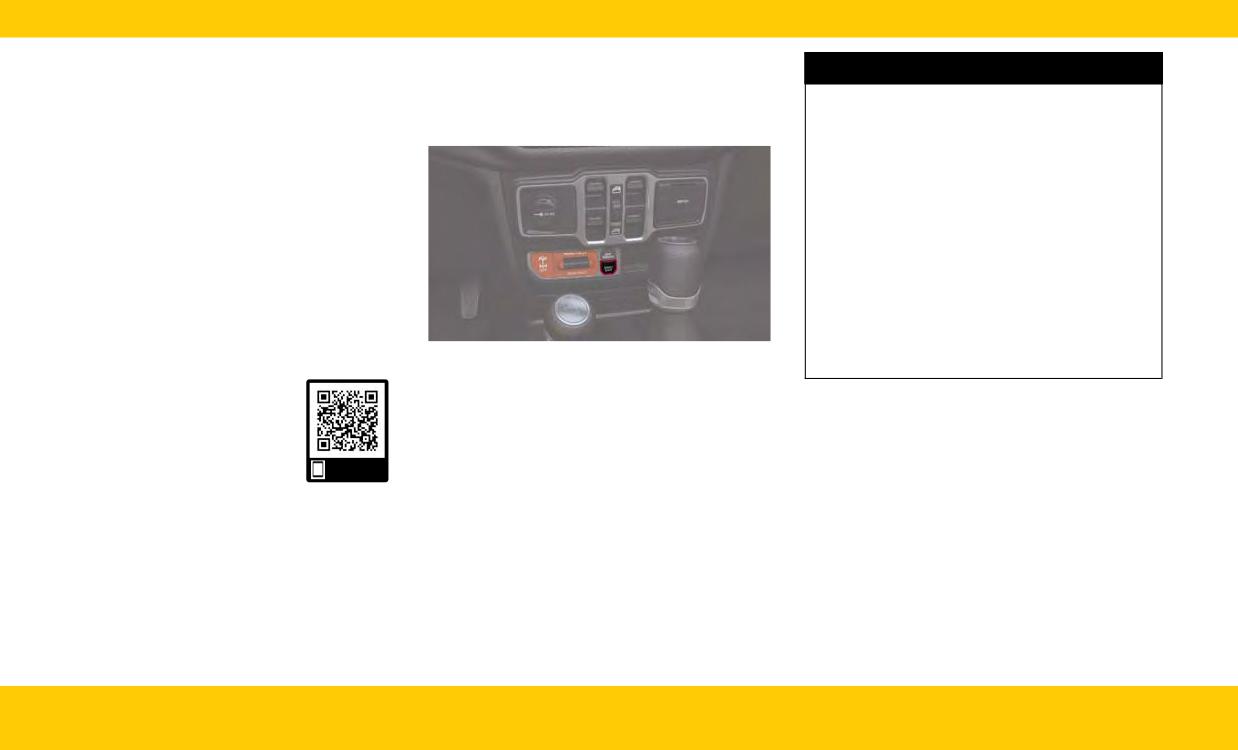
To activate the system, push the AXLE LOCK
front stabilizer/sway bar enhances vehicle sta-
switch down to lock the rear axle only. To unlock
bility and assists with vehicle control. The sys-
the rear axle, push the AXLE LOCK OFF button.
tem monitors vehicle speed and will attempt to
Axle Lock will disengage if the vehicle is taken
reconnect the stabilizer/sway bar at speeds
out of 4H, Off Road+ is turned off by the driver,
over 18 mph (29 km/h). This is indicated by a
ESC “Full Off” is exited, or the ignition switch is
flashing or solid Sway Bar Indicator Light. Once
turned to the OFF position. The rear Axle Lock
vehicle speed is reduced below 14 mph
system may temporarily disengage the rear
(22 km/h), the system will once again attempt
locker under some conditions.
SWAY BAR Switch
to return to off-road mode.
Use this QR code to access your
Push the SWAY BAR switch to activate the sys-
digital experience.
tem. Push the switch again to deactivate the sys-
NOTE:
tem. The Sway Bar Indicator Light (located in the
The stabilizer/sway bar may be torque locked
instrument cluster) will illuminate when the bar is
due to left and right suspension height differ-
disconnected. The Sway Bar Indicator Light will
Scan me
ences. This condition is due to driving surface
flash during activation transition, or when activa-
differences or vehicle loading. In order for the
tion conditions are not met. The stabilizer/sway
stabilizer/sway bar to disconnect/reconnect, the
bar should remain in on-road mode during nor-
right and left halves of the bar must be aligned.
mal driving conditions.
This alignment may require that the vehicle be
driven onto level ground or rocked from side to
side.
32
INTERIOR
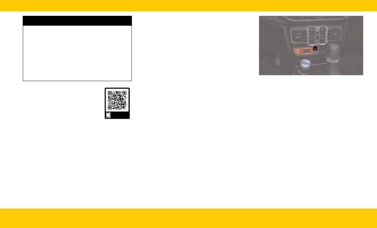
OFF ROAD+ - IF EQUIPPED
WARNING!
To activate Off Road+, push the OFF ROAD+
If the stabilizer/sway bar will not return to
switch in the switch bank when in 4WD.
on-road mode, the Sway Bar Indicator Light will
When Off Road+ is active, the following features
flash in the instrument cluster and vehicle sta-
will activate:
bility may be reduced. Do not attempt to drive
• The Off Road+ telltale will illuminate in the
the vehicle over 18 mph (29 km/h). Driving
instrument cluster display
faster than 18 mph (29 km/h) with a discon-
nected stabilizer/sway bar may contribute to
• A mode-specific message will display the
the loss of vehicle control, which could result in
instrument cluster display
serious injury.
• Off-Road Pages will launch on the radio head-
OFF ROAD+ Switch
unit if selected in radio settings
Use this QR code to access your
• The TrailCam System will launch if selected in
Once in Off Road+, the vehicle will begin to
digital experience.
radio settings
behave in different ways depending on the 4WD
mode in use.
Scan me
INTERIOR
33
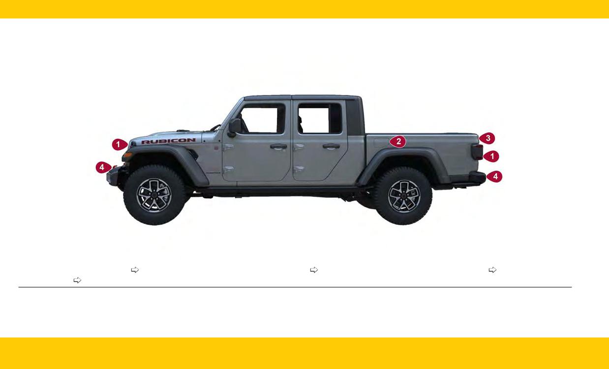
EXTERIOR OVERVIEW
1 - Exterior Camera Locations
page 35
3 - Tailgate Release Handle
page 36
4 - Emergency Tow Hook
page 47
2 - Fuel Door
page 36
34
EXTERIOR
EXTERIOR CAMERA VIEWS
HOOD
CAUTION!
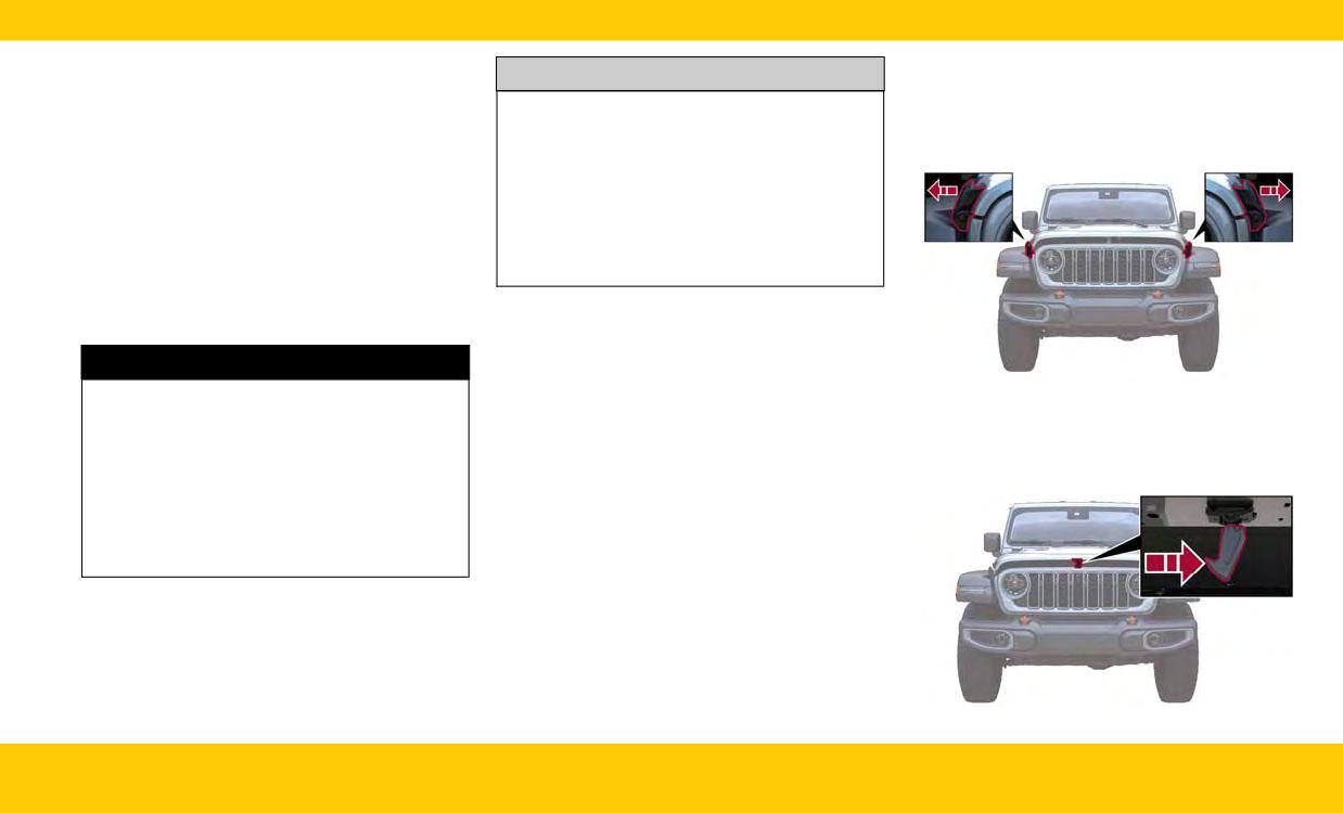
TO OPEN THE HOOD
BACK UP CAMERA
• To avoid vehicle damage, ParkView should
only be used as a parking aid. The ParkView
To open the hood:
The ParkView Rear Back Up Camera allows you
camera is unable to view every obstacle or
1. Release both of the outside hood latches.
to see an on-screen image of the rear surround-
object in your drive path.
ings of your vehicle whenever the gear selector is
• To avoid vehicle damage, the vehicle must be
put into REVERSE.
driven slowly when using ParkView to be able
Manual Activation Of The Rear View Camera:
to stop in time when an obstacle is seen. It is
1. Press the Controls button located on the bot-
recommended that the driver look frequently
tom of the Uconnect display.
over his/her shoulder when using ParkView.
2. Press the Back Up Camera button to turn the
Rear View Camera system on.
TRAILCAM SYSTEM -
WARNING!
IF EQUIPPED
The TrailCam system allows you to see an
Hood Latch Locations
Drivers must be careful when backing up even
on-screen image of the front view of your
when using the ParkView Rear Back Up Cam-
2. Raise the hood slightly, and place a hand
vehicle.
era. Always check carefully behind your vehicle,
palm-side down in the center of the hood
Manual Activation Of The TrailCam:
and be sure to check for pedestrians, animals,
opening. Locate the safety latch in the middle,
other vehicles, obstructions, or blind spots
1. Press the FWD Camera button on the controls
and push the latch to the right to open.
before backing up. You are responsible for the
screen.
safety of your surroundings and must continue
2. Press the Forward Facing Camera button on
to pay attention while backing up. Failure to do
the apps menu.
so can result in serious injury or death.
3. Press the TrailCam button on the Off-Road
Pages.
4. Press the Off Road+ button when Auto
Launch Off Road+ (if equipped) has been
selected under camera settings.
Safety Latch Location
EXTERIOR
35
3. Remove the support rod from the hood, and
REFUELING THE VEHICLE
insert it into the radiator crossmember.
CAUTION!
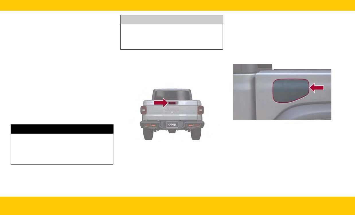
The fuel filler cap is located on the left side of the
NOTE:
To prevent possible damage, do not slam the
vehicle. To access the fuel filler cap, push on the
hood to close it. Use a firm downward push at
fuel filler door to unlatch it. To close the fuel filler
• Vehicle must be at a stop and the gear selector
the front center of the hood to ensure that
door, push on it a second time. If the fuel filler
must be in PARK.
both latches engage.
cap is lost or damaged, be sure the replacement
• Before lifting the hood, check that the wiper
cap is the correct one for this vehicle.
arms are not in motion and not in the lifted
1. Open the fuel filler door.
position.
TAILGATE
• While lifting the hood, use both hands.
OPENING
• Pressing down on the hood may need to occur
before pushing the safety latch.
TO CLOSE THE HOOD
To close the hood, remove the support rod from
the radiator crossmember, and install into the clip
on the hood. Lower the hood slowly. Secure both
of the hood latches.
Fuel Filler Door
WARNING!
Be sure the hood is fully latched before driving
your vehicle. If the hood is not fully latched, it
Tailgate Release Handle
could open when the vehicle is in motion and
block your vision. Failure to follow this warning
To open the tailgate, pull the release handle
could result in serious injury or death.
located on the center of the tailgate and guide it
to the lowered position.
The tailgate is dampened to provide a slower,
more controlled lowering.
36
EXTERIOR
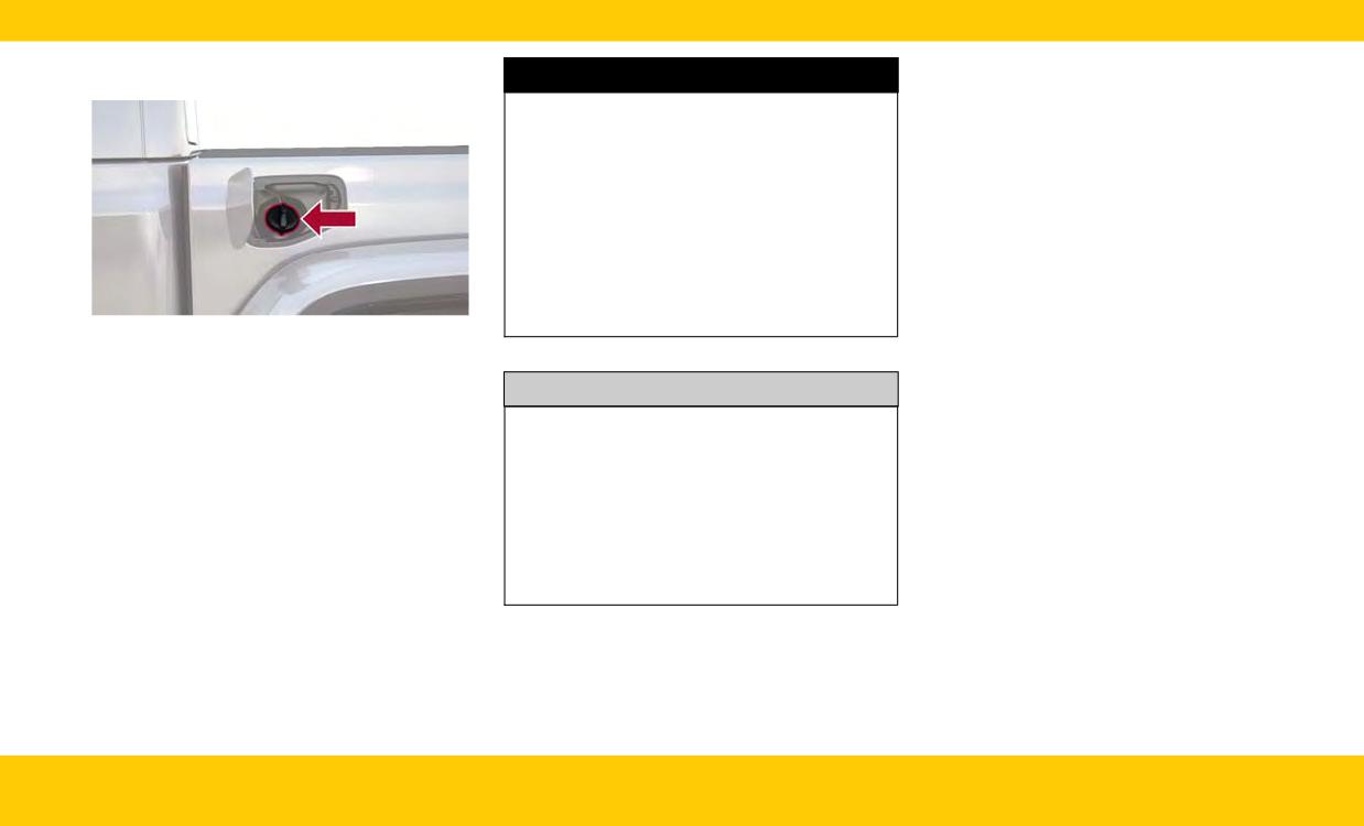
2. Remove the fuel cap by rotating it
NOTE:
counterclockwise.
WARNING!
• When the fuel nozzle “clicks” or shuts off, the
• Never have any smoking materials lit in or
fuel tank is full.
near the vehicle when the fuel door is open or
the tank is being filled.
• Tighten the fuel filler cap about a quarter turn
until you hear one click. This is an indication
• Never add fuel when the engine is running.
that the cap is properly tightened.
This is in violation of most state and federal
fire regulations and may cause the Malfunc-
• If the fuel filler cap is not tightened properly,
tion Indicator Light (MIL) to turn on.
the MIL will come on. Be sure the cap is tight-
ened every time the vehicle is refueled.
• A fire may result if fuel is pumped into a por-
table container that is inside of a vehicle. You
could be burned. Always place fuel containers
on the ground while filling.
Fuel Filler Cap
3. Fully insert the gasoline nozzle into the filler
pipe. Fill the vehicle with fuel.
CAUTION!
4. When the fuel nozzle “clicks” or shuts off, the
• Damage to the fuel system or emission con-
fuel tank is full. Wait five seconds before
trol system could result from using an
removing the fuel nozzle to allow excess fuel
improper fuel filler cap. A poorly fitting cap
to drain from nozzle.
could let impurities into the fuel system. Also,
5. Remove gasoline nozzle, reinstall fuel cap and
a poorly fitting aftermarket cap can cause the
close the fuel filler door.
Malfunction Indicator Light (MIL) to illuminate,
due to fuel vapors escaping from the system.
• To avoid fuel spillage and overfilling, do not
“top off” the fuel tank after filling.
EXTERIOR
37
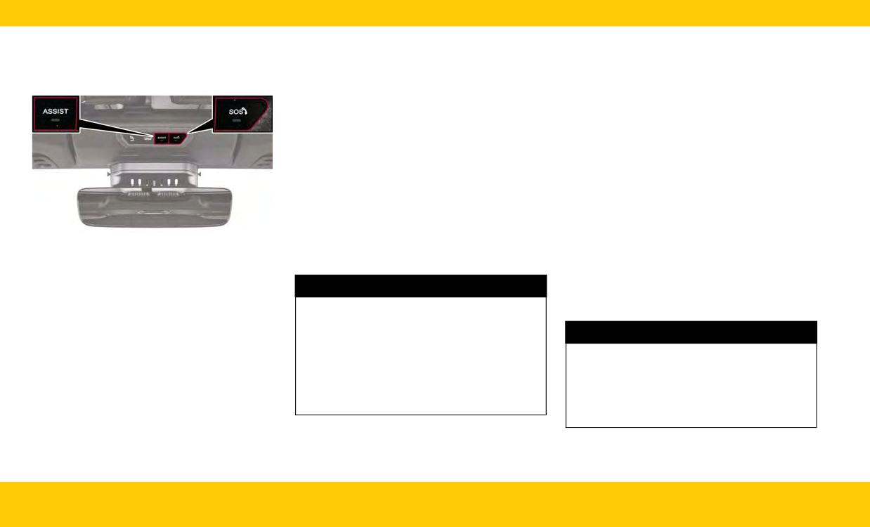
2. The LED light located next to the SOS button
NOTE:
SOS AND ASSIST SYSTEM -
on the overhead console will turn green once
○ Your vehicle may be transmitting data as
IF EQUIPPED
a connection to an SOS operator has been
authorized by the subscriber.
made.
○ Once a connection is made between the
3. Once a connection between the vehicle and
vehicle’s SOS Call system and the SOS
an SOS operator is made, the SOS Call system
operator, the SOS operator may be able to
may transmit the following important vehicle
open a voice connection with the vehicle
information to an SOS operator:
to determine if additional assistance is
needed. Once the SOS operator opens a
○ Indication that the occupant placed a SOS
voice connection with the vehicle’s SOS
Call
Call system, the operator should be able to
○ The vehicle brand
speak with you or other vehicle occupants
and hear sounds occurring in the vehicle.
○ The last known GPS coordinates of the
The vehicle’s SOS Call system will attempt
vehicle
to remain connected with the SOS opera-
4. You should be able to speak with the SOS
tor until the SOS operator terminates the
SOS Emergency Call Button
operator through the vehicle audio system to
connection.
Making an SOS Call
determine if additional assistance is needed.
5. The SOS operator may attempt to contact
1. Press or hold the SOS Call button on the over-
appropriate emergency responders and pro-
head console.
WARNING!
vide them with important vehicle information
and GPS coordinates.
NOTE:
ALWAYS obey traffic laws and pay attention to
In case the SOS Call button is pushed in error,
the road. ALWAYS drive safely with your hands
there will be a 10 second delay before the
WARNING!
on the steering wheel. You have full responsibil-
SOS Call system initiates a call to an SOS
ity and assume all risks related to the use of the
• If anyone in the vehicle could be in danger
operator. To cancel the SOS Call connection,
features and applications in this vehicle. Only
(e.g., fire or smoke is visible, dangerous road
push the SOS Call button on the overhead
use the features and applications when it is
conditions or location), do not wait for voice
console or press the cancellation button on
safe to do so. Failure to do so may result in an
contact from an Emergency Services Agent.
the Device Screen. Termination of the SOS
accident involving serious injury or death.
All occupants should exit the vehicle immedi-
Call will turn off the green LED light on the
ately and move to a safe location.
overhead console.
(Continued)
38
EMERGENCY
Making an ASSIST Call
WARNING!
WARNING!
The vehicle is equipped with an on-board assist,
• Never place anything on or near the vehicle’s
• ALWAYS obey traffic laws and pay attention
which is located within the Uconnect system. The
operable network and GPS antennas. You
to the road. ALWAYS drive safely with your
ASSIST button is used to automatically connect
could prevent operable network and GPS sig-
hands on the steering wheel. You have full
you to any one of the following support centers:
nal reception, which can prevent your vehicle
responsibility and assume all risks related to
• Roadside Assistance - If you get a flat tire, or
from placing an emergency call. An operable
the use of the features and applications in this
need a tow, just push the ASSIST button to
network and GPS signal reception is required
vehicle. Only use the features and applications
connect to someone who can help. Roadside
for the SOS Call system to function properly.
when it is safe to do so. Failure to do so may
Assistance will know what vehicle you’re driv-
result in an accident involving serious injury or
• The SOS Call system is embedded into the
ing and its location. Additional fees may apply
vehicle’s electrical system. Do not add after-
death.
for roadside assistance.
market electrical equipment to the vehicle’s
• Ignoring the overhead console light could
• Jeep Connect Customer Care - Total support
electrical system. This may prevent your
mean you will not have SOS Call services. If
for Radio, Phone and NAV issues.
vehicle from sending a signal to initiate an
the overhead console light is illuminated, have
emergency call. To avoid interference that can
an authorized dealer service the SOS Call sys-
NOTE:
cause the SOS Call system to fail, never add
tem immediately.
aftermarket equipment (e.g., two-way mobile
• The Assist and SOS buttons will only function if
• The Occupant Restraint Control module turns
you are connected to an operable LTE (voice/
radio, CB radio, data recorder, etc.) to your
on the Air Bag Warning Light on the instru-
data) or 4G (data) network, which comes as a
vehicle’s electrical system or modify the
ment panel if a malfunction in any part of the
built in function. Other Uconnect services will
antennas on your vehicle. IF YOUR VEHICLE
system is detected. If the Air Bag Warning
only be operable if your Jeep Connect service
LOSES BATTERY POWER FOR ANY REASON
Light is illuminated, have an authorized dealer
is active and you are connected to an operable
(INCLUDING DURING OR AFTER AN ACCI-
service the Occupant Restraint Control sys-
LTE (voice/data) or 4G (data) network.
DENT), THE UCONNECT FEATURES, APPS
tem immediately.
AND SERVICES, AMONG OTHERS, WILL NOT
• For further information, refer to the vehicles
OPERATE.
Uconnect Radio Instruction Manual.
Automatic SOS - If Equipped
• Modifications to any part of the SOS Call sys-
Automatic SOS is a hands-free safety service
tem could cause the air bag system to fail
that can immediately connect you with help in
when you need it. You could be injured if the
the event that your vehicle’s air bags deploy.
air bag system is not there to help protect
Please refer to your provided radio supplement
you.
for complete information.
(Continued)
EMERGENCY
39
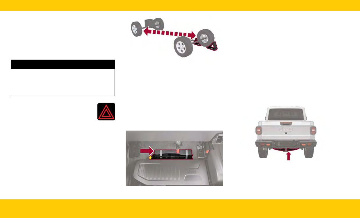
1. Fold up the right rear seat.
JACKING AND TIRE
2. Remove the jack and tools by turning the wing
CHANGING
bolt counterclockwise, remove the wing bolt
and then slide the assembly out from under
PREPARATIONS FOR JACKING
the seat.
1. Park on a firm, level surface (avoid ice or slip-
3. Release the tool bag straps from the jack and
pery areas).
remove tools from bag.
4. Remove tool kit and assemble tools.
WARNING!
Wheel Blocked
SPARE TIRE LOCATION AND
NOTE:
Do not attempt to change a tire on the side of
REMOVAL
the vehicle close to moving traffic. Pull far
• Passengers should not remain in the vehicle
when the vehicle is being raised or lifted.
Remove the spare tire before attempting to jack
enough off the road to avoid being hit when
up the truck. The spare tire is secured under the
operating the jack or changing the wheel.
• Do not attempt to change a tire on the side of
the vehicle close to moving traffic. Pull far
rear of the vehicle with a winch and cable
enough off the road to avoid being hit when
mechanism.
2. Turn on the Hazard Warning Flashers.
operating the jack or changing the wheel.
3. Apply the parking brake.
JACK LOCATION
4. Place the ignition to the OFF
The jack and tools are stored under the right rear
position.
seat.
5. Block both the front and rear of the wheel
diagonally opposite of your jacking position.
For example, if the driver’s front wheel is
being changed, block the passenger’s rear
wheel.
Spare Tire Location
1. Locate the winch access hole at the rear of the
vehicle.
2. Attach the lug wrench to the extension tubes
Jack And Tool Location
with the curved angle facing away from the
40
EMERGENCY
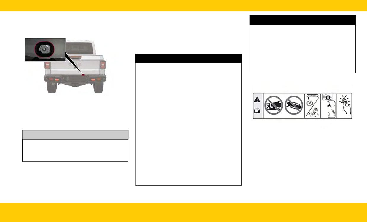
vehicle. Insert the extension tube through the
5. Lift the spare tire with one hand to give clear-
WARNING!
access hole between the lower tailgate and
ance to tilt the retainer at the end of the cable.
the top of the fascia/bumper and into the
6. Pull the retainer through the center of the
• Only use the jack in the positions indicated
winch mechanism tube.
wheel.
and for lifting this vehicle during a tire
change.
JACKING INSTRUCTIONS
• If working on or near a roadway, be extremely
careful of motor traffic.
WARNING!
• To assure that spare tires, flat or inflated, are
securely stowed, spares must be stowed with
Carefully follow these tire changing warnings to
the valve stem facing the ground.
help prevent personal injury or damage to your
vehicle:
•
Always park on a firm, level surface as far
from the edge of the roadway as possible
before raising the vehicle.
Winch Mechanism Tube
3. Rotate the lug wrench handle counterclock-
• Turn on the Hazard Warning Flashers.
wise until the spare tire is on the ground with
• Apply the parking brake firmly and shift an
enough cable slack to allow you to pull it out
automatic transmission into PARK; a manual
from under the vehicle.
transmission into REVERSE.
• Block the wheel diagonally opposite the
wheel to be raised.
CAUTION!
• Never start or run the engine with the vehicle
Jack Warning Label
The winch mechanism is designed for use with
on a jack.
1. Remove the spare tire, jack and tools from the
the jack wrench extension tool only. Use of air
• Do not let anyone sit in the vehicle when it is
stored location.
wrench or power tool may damage the winch.
on a jack.
2. Loosen (but do not remove) the wheel lug
• Do not get under the vehicle when it is on a
nuts by turning them counterclockwise one
4. Pull the spare tire out from under the vehicle
jack. If you need to get under a raised vehicle,
turn, while the wheel is still on the ground.
to gain access to the spare tire retainer.
take it to a service center where it can be
raised on a lift.
(Continued)
EMERGENCY
41
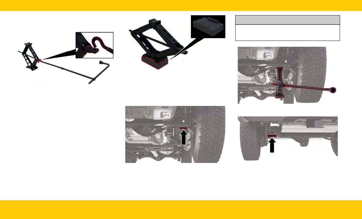
3. Assemble the jack and jacking tools. Connect
the jack handle driver to the extension, then to
CAUTION!
the lug wrench.
Do not attempt to raise the vehicle by jacking
on locations other than those indicated.
Jack Lift Box Usage
4. Operate the jack from the front or the rear of
the vehicle. Place the jack under the axle tube,
Assembled Jack And Tools
as shown. Do not raise the vehicle until you
NOTE:
are sure the jack is fully engaged.
If your vehicle comes with factory equipped
Front Jacking Location
35 inch (88.9 cm) tires, a jack lift block is pro-
vided in the rear cargo area. The jack lift
block is used to provide higher ground clear-
ance when changing a flat or spare tire. When
placing the jack lift block under the jack, be
sure the bottom of the jack fits securely
inside of the raised edges of the block.
Front Lifting Point
NOTE:
Rear Lifting Point
Keep the jack and tools aligned while raising
the vehicle to prevent tool damage.
42
EMERGENCY
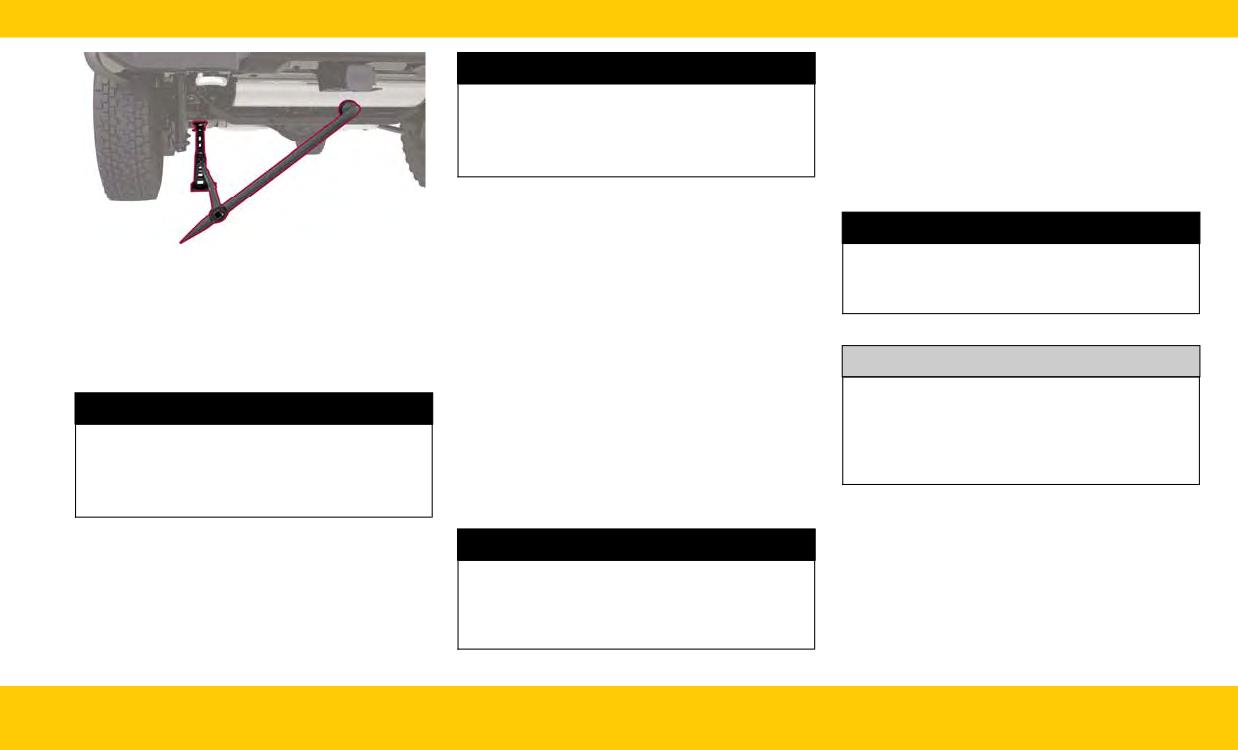
JUMP STARTING
WARNING!
If your vehicle has a discharged battery, it can be
To avoid the risk of forcing the vehicle off the
jump started using a set of jumper cables and a
jack, do not tighten the wheel nuts fully until
battery in another vehicle, or by using a portable
the vehicle has been lowered. Failure to follow
battery booster pack. Jump starting can be dan-
this warning may result in serious injury.
gerous if done improperly, so please follow the
procedures in this section carefully.
9. Lower the vehicle by turning the jack screw to
the counterclockwise, and remove the jack.
WARNING!
10. Finish tightening the wheel bolts. Push down
Rear Jacking Location
on the wrench while at the end of the handle
Do not attempt jump starting if the battery is
for increased leverage. Tighten the wheel
frozen. It could rupture or explode and cause
5. Raise the vehicle by turning the jack screw
bolts in a star pattern until each wheel bolt
personal injury.
clockwise. Raise the vehicle only until the tire
has been tightened twice. If in doubt about
just clears the surface and enough clearance is
the correct tightness, have them checked
obtained to install the spare tire. Minimum tire
with a torque wrench by an authorized dealer
CAUTION!
lift provides maximum stability.
or at a service station.
11. After 25 miles (40 km), check the lug nut
Do not use a portable battery booster pack or
WARNING!
any other booster source with a system voltage
torque with a torque wrench to ensure that all
lug nuts are properly seated against the wheel.
greater than 12 Volts or damage to the battery,
Raising the vehicle higher than necessary can
starter motor, alternator or electrical system
12. Remove the jack assembly and wheel blocks.
make the vehicle less stable. It could slip off the
may occur.
jack and hurt someone near it. Raise the vehicle
13. Secure the jack and tools in their proper
only enough to remove the tire.
locations.
NOTE:
6. Remove the lug nuts and wheel.
WARNING!
When using a portable battery booster pack, fol-
low the manufacturer's operating instructions
7. Mount the spare tire on the axle.
A loose tire or jack thrown forward in a collision
and precautions.
8. Install the lug nuts with the cone-shaped end
or hard stop, could endanger the occupants of
toward the wheel. Lightly tighten the lug nuts
the vehicle. Always stow the jack parts and the
clockwise.
spare tire in the places provided.
EMERGENCY
43
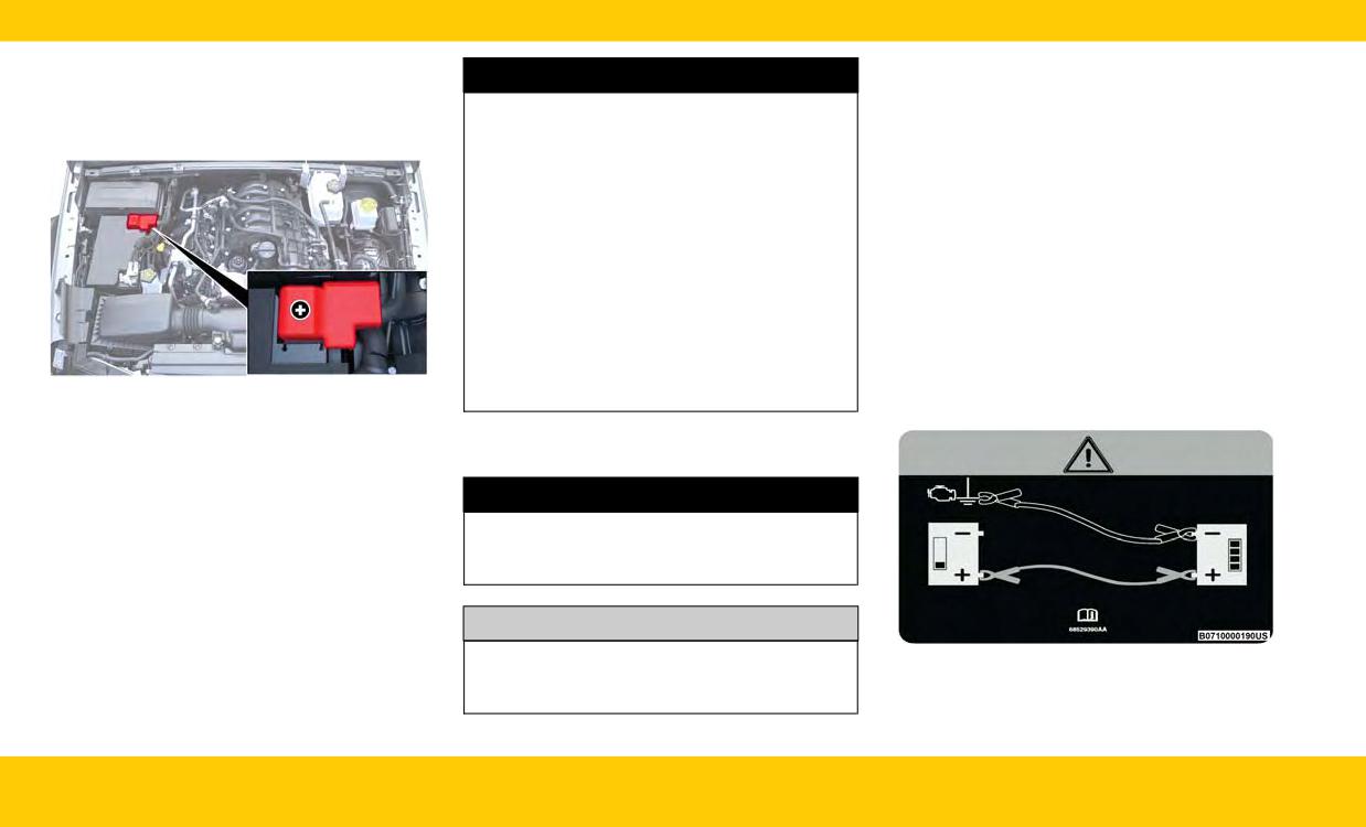
PREPARATIONS FOR JUMP
Connecting The Jumper Cables
WARNING!
1. Connect the positive (+) end of the jumper
STARTING
•
Do not allow vehicles to touch each other as
cable to the positive (+) post of the discharged
The battery in your vehicle is located in the right
this could establish a ground connection and
vehicle.
rear of the engine compartment.
personal injury could result.
2. Connect the opposite end of the positive (+)
• Take care to avoid the radiator cooling fan
jumper cable to the positive (+) post of the
whenever the hood is raised. It can start any-
booster battery.
time the ignition switch is ON. You can be
3. Connect the negative (-) end of the jumper
injured by moving fan blades.
cable to the negative (-) post of the booster
• Remove any metal jewelry such as rings,
battery.
watch bands and bracelets that could make
4. Connect the opposite end of the negative (-)
an inadvertent electrical contact. You could
be seriously injured.
jumper cable to a good engine ground. A
“ground” is an exposed metallic/unpainted
• Batteries contain sulfuric acid that can burn
part of the engine, frame or chassis, such as
your skin or eyes and generate hydrogen gas
an accessory bracket or large bolt. The ground
which is flammable and explosive. Keep open
Positive (+) Battery Post Location
flames or sparks away from the battery.
must be away from the battery and the fuel
See the following steps to prepare for jump
injection system.
starting:
1. Apply the parking brake, shift the automatic
JUMP STARTING PROCEDURE
transmission into PARK (P) (manual transmis-
sion in NEUTRAL) and place the ignition in
WARNING!
OFF mode.
Failure to follow this jump starting procedure
2. Turn off the heater, radio, and all electrical
could result in personal injury or property dam-
accessories.
age due to battery explosion.
3. Pull upward and remove the protective cover
over the positive (+) battery post.
CAUTION!
4. If using another vehicle to jump start the bat-
tery, park the vehicle within the jumper cable’s
Failure to follow these procedures could result
Jump Starting Label
reach, apply the parking brake and make sure
in damage to the charging system of the
the ignition is OFF.
booster vehicle or the discharged vehicle.
44
EMERGENCY

3. Disconnect the positive (+) end of the jumper
REVERSE (R) (with automatic transmission) or
WARNING!
cable from the positive (+) post of the booster
FIRST (1) gear and REVERSE (R) (with manual
battery.
transmission), while gently pressing the accelera-
Do not connect the jumper cable to the nega-
tor. Use the least amount of accelerator pedal
4. Disconnect the opposite end of the positive
tive (-) post of the discharged battery. The
pressure that will maintain the rocking motion,
(+) jumper cable from the positive (+) post of
resulting electrical spark could cause the bat-
without spinning the wheels or racing the engine.
the discharged vehicle.
tery to explode and could result in personal
5. Reinstall the protective cover over the positive
injury.
NOTE:
(+) post of the discharged vehicle.
•Forvehicleswithautomatictransmission:Shifts
5. Start the engine in the vehicle that has the
If frequent jump starting is required to start your
between DRIVE (D) and REVERSE (R) can only
booster battery, let the engine idle a few min-
vehicle you should have the battery and charging
be achieved at wheel speeds of 5 mph
utes, and then start the engine in the vehicle
system tested at an authorized dealer.
(8 km/h) or less. Whenever the transmission
with the discharged battery.
remains in NEUTRAL (N) for more than two
CAUTION!
seconds, you must press the brake pedal to
engage DRIVE (D) or REVERSE (R).
CAUTION!
Accessories plugged into the vehicle power
• Push the ESC OFF button to place the Elec-
outlets draw power from the vehicle’s battery,
Do not run the booster vehicle engine above
tronic Stability Control (ESC) system in “Partial
even when not in use (i.e., cellular devices, etc.).
2,000 RPM since it provides no charging ben-
OFF” mode, before rocking the vehicle. Once
Eventually, if plugged in long enough without
efit, wastes fuel, and can damage booster
the vehicle has been freed, push the ESC OFF
engine operation, the vehicle’s battery will dis-
vehicle engine.
button again to restore “ESC On” mode.
charge sufficiently to degrade battery life
and/or prevent the engine from starting.
6. Once the engine is started, follow the discon-
WARNING!
necting procedure.
Fast spinning tires can be dangerous. Forces
Disconnecting The Jumper Cables
FREEING A STUCK VEHICLE
generated by excessive wheel speeds may
1. Disconnect the negative (-) end of the jumper
cause damage, or even failure, of the axle and
cable from the engine ground of the vehicle
If your vehicle becomes stuck in mud, sand or
tires. A tire could explode and injure someone.
with the discharged battery.
snow, it can often be moved using a rocking
Do not spin your vehicle's wheels faster than
motion. Turn the steering wheel right and left to
2. Disconnect the opposite end of the negative
30 mph (48 km/h) or for longer than 30 sec-
clear the area around the front wheels. For
(-) jumper cable from the negative (-) post of
onds continuously without stopping when you
vehicles with automatic transmission, push and
the booster battery.
are stuck and do not let anyone near a spinning
hold the lock button on the gear selector. Then,
wheel, no matter what the speed.
shift back and forth between DRIVE (D) and
45
EMERGENCY

CAUTION!
CAUTION!
CAUTION!
• Racing the engine or spinning the wheels may
• When “rocking” a stuck vehicle by shifting
• Revving the engine or spinning the wheels too
lead to transmission overheating and failure.
between DRIVE/FIRST gear and REVERSE, do
fast may lead to transmission overheating and
Allow the engine to idle with the transmission
not spin the wheels faster than 15 mph
failure. It can also damage the tires. Do not
in NEUTRAL for at least one minute after
(24 km/h), or drivetrain damage may result.
spin the wheels above 30 mph (48 km/h)
every five rocking-motion cycles. This will
(Continued)
while in gear (no transmission shifting
minimize overheating and reduce the risk of
occurring).
clutch or transmission failure during pro-
longed efforts to free a stuck vehicle.
(Continued)
TOWING A DISABLED VEHICLE
This section describes procedures for towing a disabled vehicle using a commercial towing service.
If the transmission and drivetrain are operable, disabled 4x4 vehicles may also be towed as described.
Towing Condition
Wheels OFF The Ground
4WD MODELS
• Automatic Transmission in PARK (P)
• Manual Transmission in gear ( NOT in NEUTRAL)
Flat Tow
NONE
• Transfer Case in NEUTRAL (N)
• Tow in Forward direction
Front
NOT ALLOWED
Wheel Lift Or Dolly Tow
Rear
NOT ALLOWED
Flatbed
ALL
BEST METHOD
NOTE:
When towing your vehicle, always follow applicable state and provincial laws. Contact state and provincial Highway Safety offices for additional details.
46
EMERGENCY
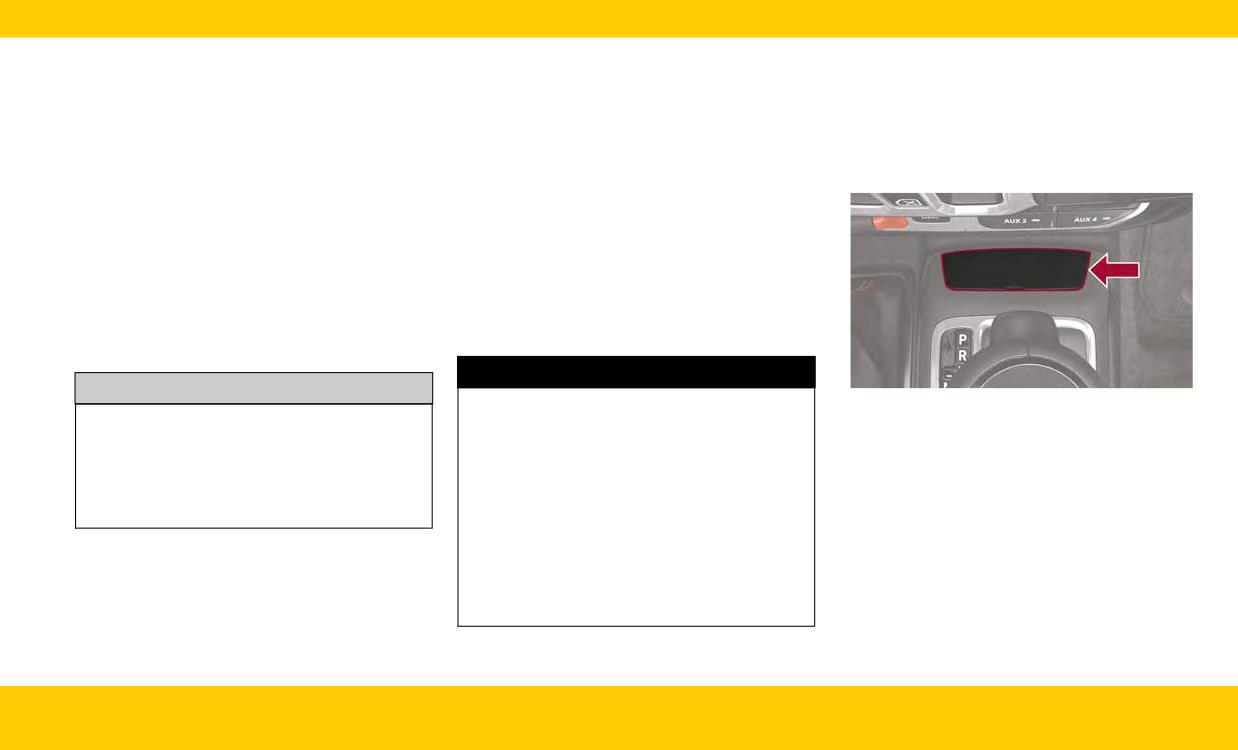
Proper towing or lifting equipment is required to
TOWING IN AN EMERGENCY
See the following steps to use the Manual Park
prevent damage to your vehicle. Use only tow
Release:
bars and other equipment designed for this pur-
Without The Key Fob
1. Firmly apply the parking brake.
pose, following equipment manufacturer’s
Special care must be taken when the vehicle is
2. Using a small screwdriver or similar tool,
instructions. Use of safety chains is mandatory.
towed with the ignition in the OFF mode. The
remove the manual park release cover located
Attach a tow bar or other towing device to main
only approved method of towing without the key
in front of the gear selector, to access the
structural members of the vehicle, not to fascia/
fob is with a flatbed truck. Proper towing equip-
release tether strap.
bumpers or associated brackets. State and local
ment is necessary to prevent damage to the
laws regarding vehicles under tow must be
vehicle.
observed.
If you must use the accessories (wipers, defrost-
Manual Park Release
ers, etc.) while being towed, the ignition must be
In order to move the vehicle in cases where the
in the ON/RUN position, not the ACC position.
transmission will not shift out of PARK (P) (such
If the vehicle's battery is discharged, instructions
as a depleted battery), a Manual Park Release is
on shifting the automatic transmission out of
available.
PARK (P) in order to move the vehicle.
WARNING!
CAUTION!
Always secure your vehicle by fully applying
Manual Park Release Cover
• Do not use sling type equipment when tow-
the parking brake before activating the Manual
ing. Vehicle damage may occur.
Park Release. In addition, you should be seated
• When securing the vehicle to a flatbed truck,
in the driver’s seat with your foot firmly on the
do not attach to front or rear suspension
brake pedal when activating the Manual Park
components. Damage to your vehicle may
Release. Activating the Manual Park Release
result from improper towing.
will allow your vehicle to roll away if it is not
secured by the parking brake, or by proper
connection to a tow vehicle. Activating the
Manual Park Release on an unsecured vehicle
could lead to serious injury or death for those
in or around the vehicle.
EMERGENCY
47
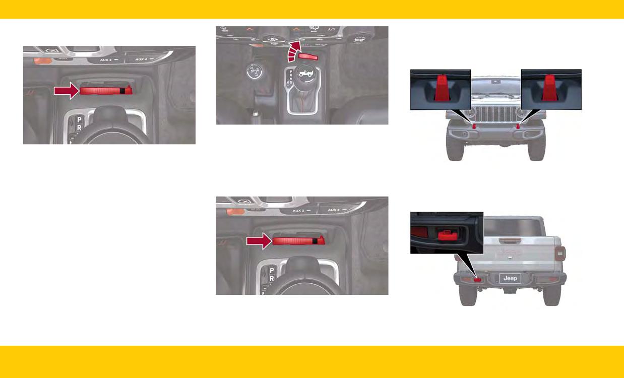
3. Fish the tether strap up through the opening
Emergency Tow Hooks - If Equipped
in the console base.
If your vehicle is equipped with tow hooks, they
are mounted in the front and the rear
fascia/bumpers.
Vertical Released Position
To Reset The Manual Park Release:
Tether Strap
1. Pull upward on the tether strap, releasing it
4. Press and maintain firm pressure on the brake
from the “locked” position.
pedal.
Front Tow Hooks
2. Lower the Manual Park Release lever down-
5. Pull the tether strap up until the release lever
NOTE:
ward and to the left, into its original position.
locks into place in the vertical position. The
Depending on vehicle trim level, rear tow hooks
vehicle is now out of PARK (P) and can be
may vary.
moved. Release the parking brake only when
the vehicle is securely connected to a tow
vehicle.
Original Tether Position
3. Tuck the tether strap into the base of the con-
Rear Tow Hook
sole, and reinstall the cover.
48
EMERGENCY
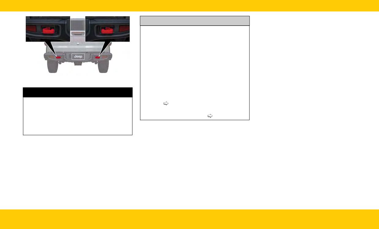
CAUTION!
• Tow hooks are for emergency use only, to res-
cue a vehicle stranded off road. Tow straps
are recommended when towing the vehicle,
chains may cause vehicle damage.
• The tow hooks must not be used to move the
vehicle off the road or where there are
obstacles.
• Do not use the tow hooks for tow truck
hookup or highway towing.
Rear Tow Hooks
• Do not use the tow hooks to pull a vehicle
onto a flatbed truck.
WARNING!
• Do not use the tow hooks to free a stuck
• Do not use a chain for freeing a stuck vehicle.
vehicle
page 45 .
Chains may break, causing serious injury or
death.
• Damage to your vehicle may occur if these
guidelines are not followed
page 46 .
• Stand clear of vehicles when pulling with tow
hooks. Tow straps may become disengaged,
causing serious injury.
EMERGENCY
49
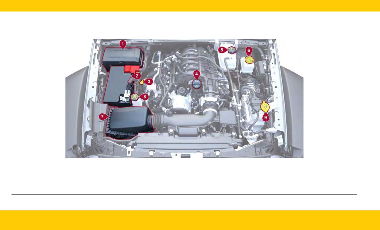
ENGINE COMPARTMENT OVERVIEW
3.6L ENGINE
1 - Power Distribution Center (Fuses)
6 - Brake Fluid Reservoir Cap
2 - Battery
7 - Engine Air Cleaner, Filter
3 - Engine Oil Dipstick
8 - Power Steering Fluid Reservoir Cap
4 - Engine Oil Fill
9 - Washer Fluid Reservoir Cap
5 - Engine Coolant Pressure Cap
50
SPECIFICATIONS
FLUID CAPACITIES
US
Metric
Fuel (Approximate)
22.0 gal
83.0 L
Engine Oil with Filter
3.6L Engine
5.0 qt
4.7 L
Cooling System *
3.6L Engine
13.0 qt
12.3 L
*Includes coolant recovery bottle filled to MAX level.
ENGINE FLUIDS AND LUBRICANTS
Component
Fluid, Lubricant, or Genuine Part
We recommend using Mopar® Antifreeze/Coolant 10 Year/150,000 Mile (240,000 km) Formula OAT
Engine Coolant
(Organic Additive Technology) or equivalent meeting the requirements of the manufacturer Material
Standard MS.90032.
We recommend using Mopar® SAE 0W-20 Full Synthetic Engine Oil which meets the requirements
Engine Oil - 3.6L Gasoline Engine
of the manufacturer Material Standard MS-6395. Equivalent full synthetic SAE 0W-20 engine oil can
be used but must have the API Starburst trademark.
Fuel Selection - 3.6L Gasoline Engine
87 Octane (R+M)/2 Method, 0-15% Ethanol.
CAUTION!
• Mixing of engine coolant (antifreeze) other than specified Organic Additive Technology (OAT) engine coolant (antifreeze), may result in engine damage
and may decrease corrosion protection. Organic Additive Technology (OAT) engine coolant is different and should not be mixed with Hybrid Organic
Additive Technology (HOAT) engine coolant (antifreeze) or any “globally compatible” coolant (antifreeze). If a non-OAT engine coolant (antifreeze) is
introduced into the cooling system in an emergency, the cooling system will need to be drained, flushed, and refilled with fresh OAT coolant (conforming
to MS.90032), by an authorized dealer as soon as possible.
• Do not use water alone or alcohol-based engine coolant (antifreeze) products. Do not use additional rust inhibitors or antirust products, as they may not
be compatible with the radiator engine coolant and may clog the radiator.
• This vehicle has not been designed for use with propylene glycol-based engine coolant (antifreeze). Use of propylene glycol-based engine coolant (anti-
freeze) is not recommended.
SPECIFICATIONS
51

CHASSIS FLUIDS AND LUBRICANTS
Component
Fluid, Lubricant, or Genuine Part
Use only Mopar® ZF 8 & 9 Speed ATF Automatic Transmission Fluid or equivalent. Failure to
Automatic Transmission - If Equipped
use the correct fluid may affect the function or performance of your transmission.
Manual Transmission - If Equipped
We recommend using Mopar® ATF+4 Automatic Transmission Fluid.
Transfer Case
We recommend using Mopar® ATF+4 Automatic Transmission Fluid.
Front Axle Differential
We recommend using Mopar® Gear & Axle Lubricant (SAE 75W85) (API GL-5).
We recommend using Mopar® Gear & Axle Lubricant (SAE 75W85) (API GL-5). Models
Rear Axle Differential (M220 Sales Codes DRE/DRF)
equipped with Trac-Lok Limited Slip Differential require a friction modifier additive.
Brake Master Cylinder
We recommend using Mopar® DOT 3 Brake Fluid, SAE J1703.
Power Steering Reservoir
We recommend using Mopar® Electric Steering Pump Fluid.
SERVICING AND
• Inspect the CV/Universal joints.
WARNING!
• Inspect brake pads, shoes, rotors, drums, hoses
MAINTENANCE
and parking brake.
• You can be badly injured working on or
around a motor vehicle. Do only service work
• Inspect the engine cooling system protection
MAINTENANCE PLAN
for which you have the knowledge and the
and hoses.
right equipment. If you have any doubt about
Your vehicle will remind you that it is time to take
• Inspect the exhaust system.
your ability to perform a service job, take your
your vehicle in for scheduled maintenance.
• Inspect the engine air cleaner filter if using in
vehicle to a competent mechanic.
At Every Oil Change Interval As Indicated By Oil
dusty or off-road conditions; replace the
Change Indicator System
• Failure to properly inspect and maintain your
engine air cleaner filter as necessary.
vehicle could result in a component malfunc-
• Change the oil and filter.
• Inspect all door latches for presence of grease;
tion and affect vehicle handling and perfor-
reapply if necessary.
• Rotate the tires (Rotate at the first sign of
mance. This could cause an accident.
irregular wear, even if it occurs before the oil
indicator system turns on).
• Inspect battery and clean and tighten terminals
as required.
52
SPECIFICATIONS
OIL CHANGE RESET -
ENGINE BREAK-IN
TRAILER TOWING
IF EQUIPPED
RECOMMENDATIONS
WEIGHTS (MAXIMUM
• Your vehicle may be equipped with an engine
A long break-in period is not required for the
TRAILER WEIGHT
oil change indicator system. The change oil
engine and drivetrain (transmission and axle) in
message will display in the instrument cluster
your vehicle.
RATINGS)
display for five seconds after a single chime
Drive moderately during the first 300 miles
has sounded, to indicate the next scheduled oil
(500 km). After the initial 60 miles (100 km),
NOTE:
change. The engine oil change indicator system
speeds up to 50 or 55 mph (80 or 90 km/h) are
For trailer towing information (maximum trailer
is duty cycle based, which means the engine oil
desirable.
weight ratings) refer to the following website
change interval may fluctuate, depending upon
While cruising, brief full-throttle acceleration
addresses:
your personal driving style.
within the limits of local traffic laws contributes
• jeep.com/gladiator/specs
• Unless reset, this message will continue to dis-
to a good break-in. You should avoid wide-open
play each time the ignition is cycled to the
throttle acceleration in low gear as it can be
• jeep.ca (Canada)
ON/RUN position.
detrimental.
To reset the oil change indicator after performing
The engine oil installed in the engine at the fac-
the scheduled maintenance, refer to the follow-
tory is a high-quality energy conserving type
ing procedure:
lubricant. Oil changes should be consistent with
1. Without pushing the brake pedal, place the
anticipated climate conditions under which
ignition in the ON/RUN mode (do not start the
vehicle operations will occur. For the recom-
engine).
mended viscosity and quality grades
2. Fully press the accelerator pedal, slowly, three
page 51 .
times within ten seconds.
3. Without pushing the brake pedal, place the
CAUTION!
ignition in the OFF position.
Never use Non-Detergent Oil or Straight Min-
NOTE:
eral Oil in the engine or damage may result.
If the indicator message illuminates when you
start the vehicle, the oil change indicator system
did not reset. If necessary, repeat this procedure.
SPECIFICATIONS
53
A
Camera, Rear
35
Fuel Requirements
51
Adaptive Cruise Control (ACC)
. . . .29
Capacities, Fluid
51
Jump Starting
43
Adaptive Cruise Control (ACC) (Cruise
Caps, Filler
Oil
51
Control)
27
Fuel
36
Oil Filler Cap
50
Air Conditioning
22
Oil (Engine)
50
Oil Selection
51
Android Auto
12
Climate Control
22
Exterior Lights
25
Android Auto™
. . . . . . . . . . . . . . .12
Automatic
22
Antifreeze (Engine Coolant)
51
Climate Controls
. . . . . . . . . . . . . .22
Apple CarPlay®
. . . . . . . . . . . . . . .11
Contract, Service
6
F
Automatic Headlights
26
Cooling System
Filters
Automatic High Beams
26
Cooling Capacity
51
Engine Oil
51
Fluid, Brake
52
Automatic Temperature Control (ATC) . .23
Selection Of Coolant (Antifreeze)
51
Fluid Capacities
51
Automatic Transmission
Cruise Control (Speed Control)
27
Fluid Type
52
Customer Assistance
5
Fog Lights
25
Axle Fluid
52
Freeing A Stuck Vehicle
45
Axle Lock
31
Front View Camera
35
Axle Lock (Tru-Lok) Front And
D
Fuel
Rear
. . . . . . . . . . . . . . . . . . . .31
Defroster, Windshield
22
Filler Cap (Gas Cap)
36
Axle Lock (Tru-Lok) Rear Only
. . . . .32
Dimmer Control Switch
25
Octane Rating
51
Requirements
51
Specifications
51
B
E
Tank Capacity
51
Back Up Camera
35
Electrical Power Outlets
13
Basic Voice Commands
. . . . . . . . . .12
Electronic Sway Bar Disconnect
. . . .33
Brake Fluid
52
Emergency, In Case Of
G
Jump Starting
43
Garage Door Opener (HomeLink®)
. .29
Engine
50
Gas Cap (Fuel Filler Cap)
36
C
Break-In Recommendations
53
Camera
35
Compartment
50
Camera, Front
35
Coolant (Antifreeze)
51
54
INDEX
H
Fog
25
P
Headlights
Headlights
25, 26
Pair/Delete A Device
. . . . . . . . . . . .11
Switch
25
Locking
ParkSense Rear Park Assist System
. .31
HomeLink® (Garage Door Opener)
29
Axle
31
Passive Entry
9
How To Turn Off The Stop/Start
Power
System
. . . . . . . . . . . . . . . . . . .9
Inverter
14
M
Outlet (Auxiliary Electrical Outlet) . . .13
Manual
Seats
24
I
Service
6
Power Steering Fluid
52
Instrument Cluster
16
Manual Park Release
47
Descriptions
16
Manual Transmission
Inverter
Lubricant Selection
52
R
Power
14
Media Hub
15
Radio
MP3 Control
15
Settings
10
Rear ParkSense System
30
J
Jacking Instructions
41
N
Jack Location
40
New Vehicle Break-In Period
53
S
Jack Operation
41
Seats
Jump Starting
43
Power
24
O
Second Row USB
15
Octane Rating, Gasoline (Fuel)
51
Selection Of Coolant (Antifreeze)
51
Oil Change Indicator
K
Service Assistance
5
Keyless Enter'n Go™
9
Reset
53
Service Contract
6
Keyless Enter ‘n Go™ - Passive
Oil, Engine
51
Service Manuals
6
Entry
. . . . . . . . . . . . . . . . . . . .9
Capacity
51
SOS Call
38
Filter
51
Spare Tires
40
Recommendation
51
Specifications
L
Viscosity
51
Fuel (Gasoline)
51
Lights
Operator Manual
Oil
51
Exterior
25
Owner's Manual
6
INDEX
55
Speed Control (Cruise Control)
27
U
Steering
Uconnect
Wheel, Voice Recognition
12
Uconnect Settings
10
Stop/Start
9
Uconnect Phone
11
Stuck, Freeing
45
Pair (Link) Uconnect Phone To A Mobile
Sway Bar Disconnect
Phone
11
Electronic
32
Uconnect Settings
. . . . . . . . . . . . .11
Uconnect System
10
USB
15
T
Tailgate
36
Temperature Control, Automatic (ATC). .23
V
Tires
Vehicle Settings
10
Spare Tires
40
Voice Command
12
To Open Hood
35
Voice Recognition System (VR)
12
Tow Hooks
Emergency
48
W
Towing
46, 53
Warning Lights And Messages
17
Disabled Vehicle
46
Warranty Information
. . . . . . . . . . .6
Weight
53
Windshield Washers
26
TrailCam System
35
Windshield Wipers
26
Trailer Towing
Trailer And Tongue Weight
53
Trailer Towing Guide
53
Trailer Weight
53
Transfer Case
Fluid
52
Transmission
Fluid
52
56
INDEX