Cisco 910 Industrial Router Hardware. Installation Guide (2015)

Cisco 910 Industrial Router Hardware
Installation Guide
First Published: July 8, 2014
Last Updated: May 12, 2015
THE SPECIFICATIONS AND INFORMATION REGARDING THE PRODUCTS IN THIS MANUAL ARE SUBJECT TO CHANGE
WITHOUT NOTICE. ALL STATEMENTS, INFORMATION, AND RECOMMENDATIONS IN THIS MANUAL ARE BELIEVED TO
BE ACCURATE BUT ARE PRESENTED WITHOUT WARRANTY OF ANY KIND, EXPRESS OR IMPLIED. USERS MUST TAKE
FULL RESPONSIBILITY FOR THEIR APPLICATION OF ANY PRODUCTS.
THE SOFTWARE LICENSE AND LIMITED WARRANTY FOR THE ACCOMPANYING PRODUCT ARE SET FORTH IN THE
INFORMATION PACKET THAT SHIPPED WITH THE PRODUCT AND ARE INCORPORATED HEREIN BY THIS REFERENCE.
IF YOU ARE UNABLE TO LOCATE THE SOFTWARE LICENSE OR LIMITED WARRANTY, CONTACT YOUR CISCO
REPRESENTATIVE FOR A COPY.
The following information is for FCC compliance of Class A devices: This equipment has been tested and found to comply
with the limits for a Class A digital device, pursuant to part 15 of the FCC rules. These limits are designed to provide
reasonable protection against harmful interference when the equipment is operated in a commercial environment. This
equipment generates, uses, and can radiate radio-frequency energy and, if not installed and used in accordance with
the instruction manual, may cause harmful interference to radio communications. Operation of this equipment in a
residential area is likely to cause harmful interference, in which case users will be required to correct the interference at
their own expense.
The following information is for FCC compliance of Class B devices: This equipment has been tested and found to comply
with the limits for a Class B digital device, pursuant to part 15 of the FCC rules. These limits are designed to provide
reasonable protection against harmful interference in a residential installation. This equipment generates, uses and can
radiate radio frequency energy and, if not installed and used in accordance with the instructions, may cause harmful
interference to radio communications. However, there is no guarantee that interference will not occur in a particular
installation. If the equipment causes interference to radio or television reception, which can be determined by turning the
equipment off and on, users are encouraged to try to correct the interference by using one or more of the following
measures:
Reorient or relocate the receiving antenna.
Increase the separation between the equipment and receiver.
Connect the equipment into an outlet on a circuit different from that to which the receiver is connected.
Consult the dealer or an experienced radio/TV technician for help.
Modifications to this product not authorized by Cisco could void the FCC approval and negate your authority to operate
the product.
The Cisco implementation of TCP header compression is an adaptation of a program developed by the University of
1
Preface
Audience
Preface
Audience
This guide is for networking or computer technicians responsible for installing the Cisco 910 Industrial Routers. We
assume that you are familiar with the concepts and terminology of Ethernet and local area networking.
Purpose
This guide documents the hardware features of the Cisco 910 Industrial Routers. It describes the physical and
performance characteristics of the router, explains how to install a router, and provides troubleshooting information.
For configuration information, see the Cisco 910 Industrial Routers documentation on Cisco.com. For system
requirements, important notes, limitations, open and resolved bugs, and documentation updates, see the Cisco 910
Industrial Router release notes on Cisco.com.
Conventions
This document uses the following conventions and symbols for notes, cautions, and warnings.
Note: Means reader take note. Notes contain helpful suggestions or references to materials not contained in this manual.
Caution: Means reader be careful. In this situation, you might do something that could result in equipment damage
or loss of data.
Warning: This warning symbol means danger. You are in a situation that could cause bodily injury. Before you work
on any equipment, be aware of the hazards involved with electrical circuitry and be familiar with standard practices
for preventing accidents. Use the statement number provided at the end of each warning to locate its translation in
the translated safety warnings that accompanied this device. Statement 1071
Related Publications
Before installing, configuring, or upgrading the router, see the release notes on Cisco.com for the latest information.
These documents provide complete information about the router and are available on Cisco.com:
Cisco 910 Industrial Router Quick Start Guide
Mounting Kit Assembly Guide for the Cisco 910 Industrial Router
Release Notes for the Cisco 910 Industrial Router
Cisco 910 Industrial Router Software Configuration Guide
Obtaining Documentation and Submitting a Service Request
For information on obtaining documentation, using the Cisco Bug Search Tool (BST), submitting a service request, and
gathering additional information, see What’s New in Cisco Product Documentation at:
http://www.cisco.com/c/en/us/td/docs/general/whatsnew/whatsnew.html.
Subscribe to What’s New in Cisco Product Documentation, which lists all new and revised Cisco technical
documentation as an RSS feed and delivers content directly to your desktop using a reader application. The RSS feeds
are a free service.
5
Preface
Related Publications
6

Router Models
Overview of the Cisco 910 Industrial
Router
The Cisco 910 Industrial Router provides a rugged and secure routing infrastructure for harsh environments. It is suitable
for Internet of Things (IoT) applications, various smart or intelligent nodes, such as wireless sensor, mobile terminals,
RFID, and so on.
You can mount the router on a DIN rail, or on a wall or a pole by using the IP55 enclosure and wall or pole mount kit.
This chapter describes the Cisco 910 Industrial Router, hereafter referred to as the router.
This chapter provides a functional overview of the router and covers these topics:
Router Models, page 7
Front-Panel Description, page 7
Rear Panel Description, page 18
Power Supply Adapter (Optional), page 18
Router Models
Table 1 describes the available models for the router: IR910-K9, IR910G-K9, and IR910W-K9.
IR910-K9 supports only the Ethernet combo uplink. IR910W-K9 supports both the Wi-Fi and Ethernet combo uplink.
IR910G-K9 supports both the 3G (CDMA-EVDO/HSPA selective) and Ethernet combo uplink.
Note: If you are using the 3G models of Cisco 910 Industrial Routers, the Mobile Equipment Identifier (MEID), International
Mobile Equipment Identity (IMEI), and Electronic Serial Number (ESN) are necessary for Verizon customers to set up the
3G interface. You can use the show cellular unit all command to display MEID, IMEI, and ESN information. For more
information, see the “Monitoring Cellular 3G Information” section in Chapter 20, Configuring Cellular 3G Setting, of the
Cisco 910 Industrial Router Software Configuration Guide.
Table 1
Cisco 910 Industrial Router Models
Router Model
Description
IR910-K9
Cisco 910 Industrial Router (Ethernet only)
IR910G-K9
Cisco 910 Industrial Router (3G and Ethernet)
IR910G-NA-K9
IR910W-K9
Cisco 910 Industrial Router (WiFi and Ethernet)
Front-Panel Description
This section describes the front panel and includes these subsections:
Console Port, page 10
USB Port, page 10
Serial Port, page 11
Gigabit Ethernet Port, page 11
7
Front-Panel Description
Small Form-Factor Pluggable Port, page 12
Combo Port (GE and SFP), page 12
SSD Slot, page 12
Open Slot, page 12
SIM Card Slot (IR910G-K9 and IR910G-NA-K9 Only), page 13
Power Connector, page 13
LEDs, page 13
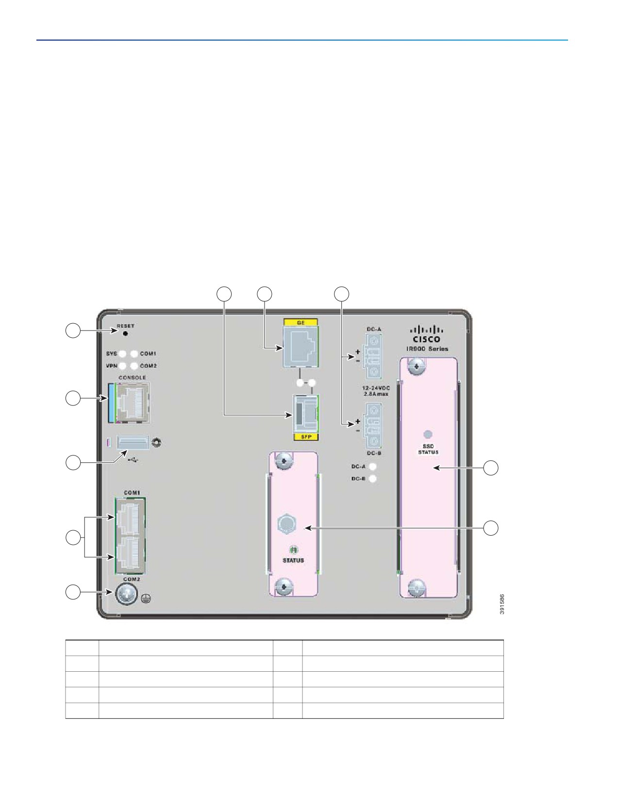
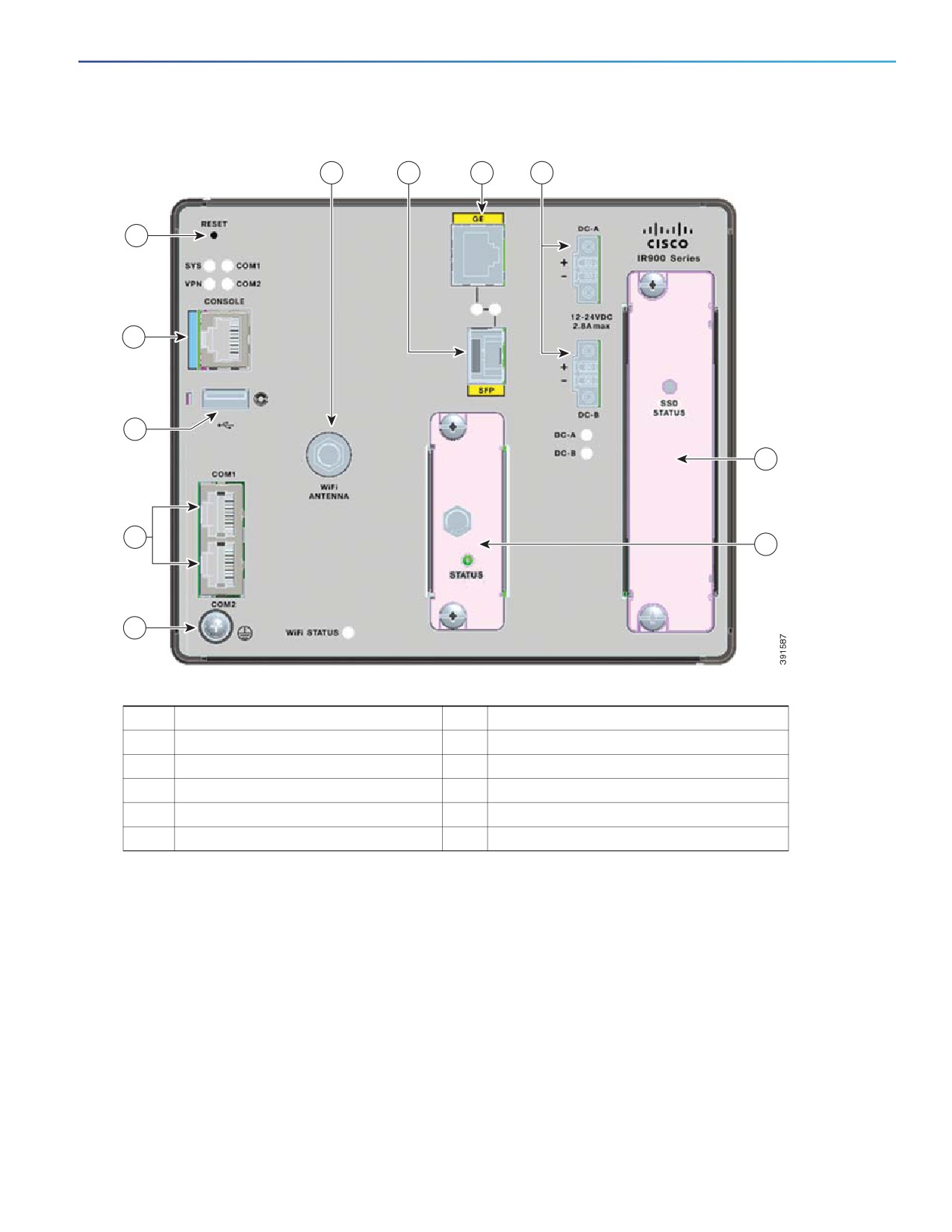
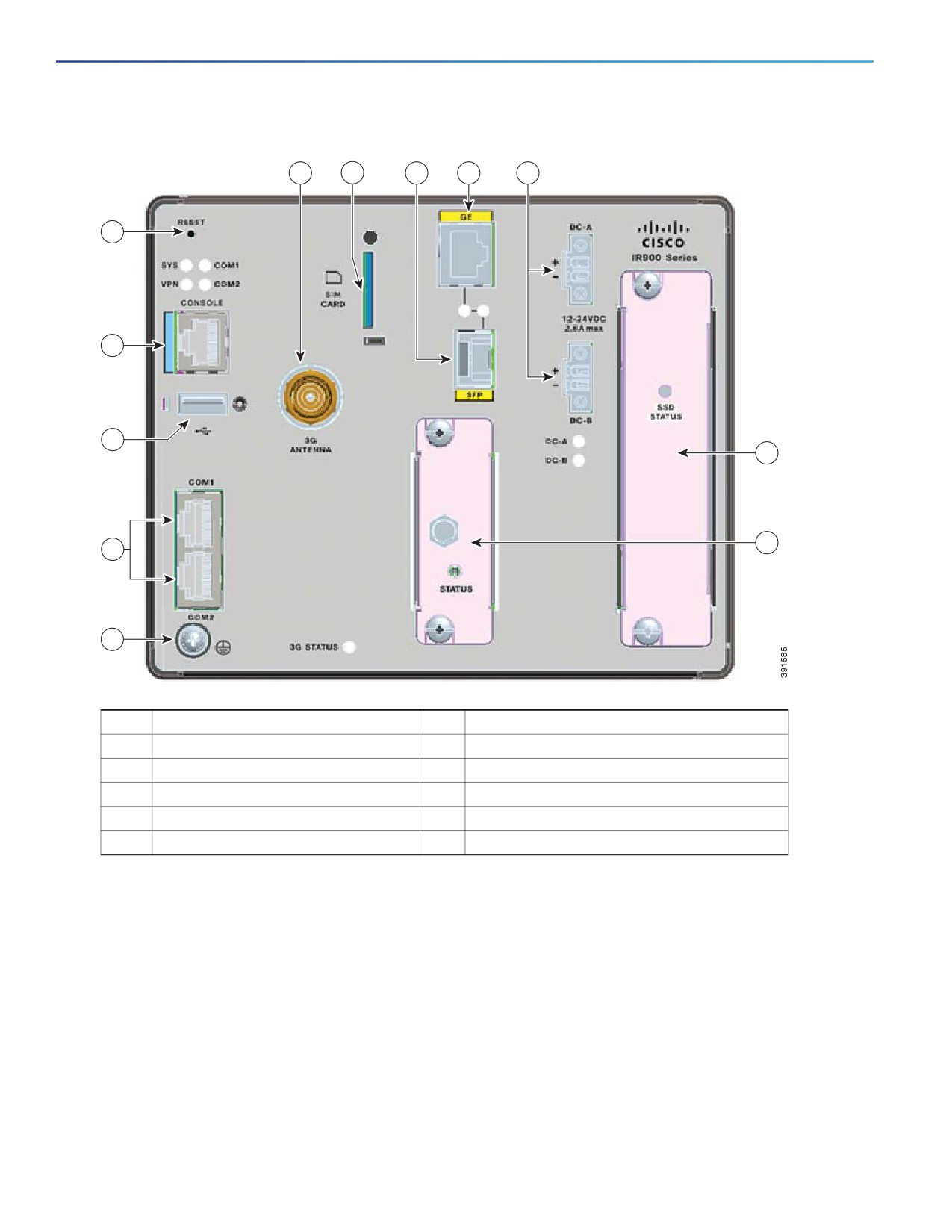
The front panel of the router contains ports, LEDs, and power connectors. Figure 1, Figure 2, and Figure 3 show the front
panels.
Figure 1
Front Panel of IR910-K9
5
4
6
9
1
2
7
8
3
10
1
Console port
6
Power connectors
2
USB port
7
SSD slot
3
Serial ports
8
Open slot
4
GE port
9
Reset button
5
SFP port
10
Grounding screw
8
Front-Panel Description
Figure 2
Front Panel of IR910W-K9
11
5
4
6
9
1
2
7
3
8
10
1
Console port
7
SSD slot
2
USB port
8
Open slot
3
Serial ports
9
Reset button
4
GE port
10
Grounding screw
5
SFP port
11
Wi-Fi antenna
6
Power connectors
9
Front-Panel Description
Figure 3
Front Panel of IR910G-K9/IR910G-NA-K9
12
11
5
4
6
9
1
2
7
8
3
10
1
Console port
7
SSD slot
2
USB port
8
Sensor card slot
3
Serial ports
9
Reset button
4
GE port
10
Grounding screw
5
SFP port
11
SIM card slot
6
Power connectors
12
3G antenna
The R910G-NA-K9 model will be equipped with a dummy SIM card in the SIM card slot by default. If the your service
provider require that you use an actual SIM card, replace the dummy SIM card with an actual one.
Console Port
You can connect the router to a PC through the console port and an RJ-45-to-DB-9 adapter cable. If you want to connect
the router to a terminal, you need an RJ-45-to-DB-25 female Data Terminal Equipment (DTE) adapter.
USB Port
The router has a standard USB 2.0 port for connecting and powering an optional USB peripheral device. The port also
supports USB devices that are powered by an external source, such as an AC adapter or batteries.
10
Front-Panel Description
Connection Considerations
Depending on the USB devices you connect to these ports, you might require a USB extension cable to connect
devices to these ports.
To prevent USB devices from being stolen or accidentally removed, secure any connected USB device with a locking
mechanism.
Specifications
Specification
Description
USB Port Type
Type A
USB Device Types Supported
USB 2.0
Power Output
2.5W (+5V +/-5% @ 500mA)
Serial Port
The router has two serial ports for connection to legacy devices, such as remote terminal units (RTUs). These ports
support the following modes (selected with system software commands):
RS232
RS485
Before you connect a device to a serial port, you need to know the following:
Type of device, data terminal equipment (DTE) or data communications equipment (DCE), you are connecting to the
synchronous serial interface
Signaling standard required by the device
Serial ports can be configured as DTE or DCE, depending on the serial cable used
Serial Port Cables
You can order a Cisco RJ-45 shielded serial transition cable that has the appropriate connector for the standard you
specify. The documentation for the device should indicate the standard used for that device. The router end of the
shielded serial transition cable has a DB-25 connector, which connects to the DB-25 port on a serial grid router WAN
interface card. The other end of the serial transition cable is available with a connector that is appropriate for the standard
you specify. The synchronous serial port can be configured as DTE or DCE, depending on the attached cable.
Gigabit Ethernet Port
The router has a Gigabit Ethernet port that can be used to enable WAN connectivity to a primary substation or a control
center. The port is shown in Figure 1.
The interface is also used by the small form-factor pluggable (SFP) ports (see Small Form-Factor Pluggable Port. For
more information about how these ports are used together, see Combo Port (GE and SFP).
The GE port automatically detects the type of any connected cable (fiber or copper) and then switches to the
corresponding mode (fiber or copper). When both cables types are connected to the router, the first cable that
establishes a link is enabled.
11

Front-Panel Description
Small Form-Factor Pluggable Port
The router has a fiber optical SFP port that supports optional rugged SFP modules for Gigabit Ethernet WAN connectivity
to a primary substation or control center.
The interface is also used by the Gigabit Ethernet port (see Gigabit Ethernet Port). For more information about how these
ports are used together, see Combo Port (GE and SFP).
Hot Swapping SFP Modules
The SFP modules can be installed or removed while the router is on and operating normally.
Supported SFPs
Table 2 lists the supported SFP modules.
See the Cisco 910 Industrial Router Release Notes for the most recent information about supported hardware and
software.
Table 2
Supported SFP Modules
Cisco Product ID
Description
GLC-SX-MM
1000BASE-SX short wavelength
GLC-LH-SM
1000BASE-LX/LH long wavelength
GLC-SX-MM-RGD
1000BASE-SX short wavelength; rugged
GLC-LX-SM-RGD
1000BASE-LX/LH long wavelength; rugged
GLC-FE-100LX-RGD
100BASE-LX10 SFP; rugged
GLC-FE-100FX-RGD
100BASE-FX SFP; rugged
Combo Port (GE and SFP)
The combo port is a Gigabit Ethernet port and an SFP port on the router, with both sharing the same physical port or
connection.
The Gigabit Ethernet port supports copper GE connections, and the SFP module supports fiber optic GE connections.
Only one connection on the interface can be in use at any time.
The port automatically detects the type of any connected cable (fiber or copper) and then switches to the corresponding
mode (fiber or copper). When both cables types are connected to the router, the first cable that establishes a link is
enabled.
SSD Slot
The router has an SSD slot for you to install an external storage to support information storage. You can order an SSD
storage (model number ACC-IR910-S16) separately.
When the SSD storage is installed, the operating temperature should not exceed 140°F (60°C) to prevent the system
from overheating.
Open Slot
The router has an open slot to install Cisco modular card (i.e. Cisco IR910 LoRa card, ACC-IR910-LoRa-868) or partners’
modular card.
12

Front-Panel Description
SIM Card Slot (IR910G-K9 and IR910G-NA-K9 Only)
The router has a 3G SIM card slot for the IR910G-K9 and IR910G-NA-K9 model to support 3G functions.
The R910G-NA-K9 model will be equipped with a dummy SIM card in the SIM card slot by default. If the your service
provider require that you use an actual SIM card, replace the dummy SIM card with an actual one.
Power Connector
Connect the DC power to the router through the two front panel connectors. One connector provides primary DC power
(supply A), and a second connector (supply B) provides secondary power. The two connectors are physically identical
and are in the upper right side of the front panel. See Figure 1.
The router accessory pack includes the mating power connector jacks (see Figure 4). These power connector jacks
provide screw terminals for terminating the DC power and the connector plugs into the power receptacles on the front
panel.
Figure 4
Power Connector Jack
The router can operate with a single power source or dual power sources. When both the power sources are operational,
the router draws power from the DC source with the higher voltage. If one of the two power sources fail, the other
continues to power the router.
Reset Button
The Reset button is located on the top left of the router front panel (see Figure 1). It can be used to reboot the system
or revert the configuration to factory mode. Use the Reset button as follows:
To reboot the entire system, press the Reset button and release it immediately.
To revert to the factory mode, press and hold the Reset button for more than 5 seconds.
LEDs
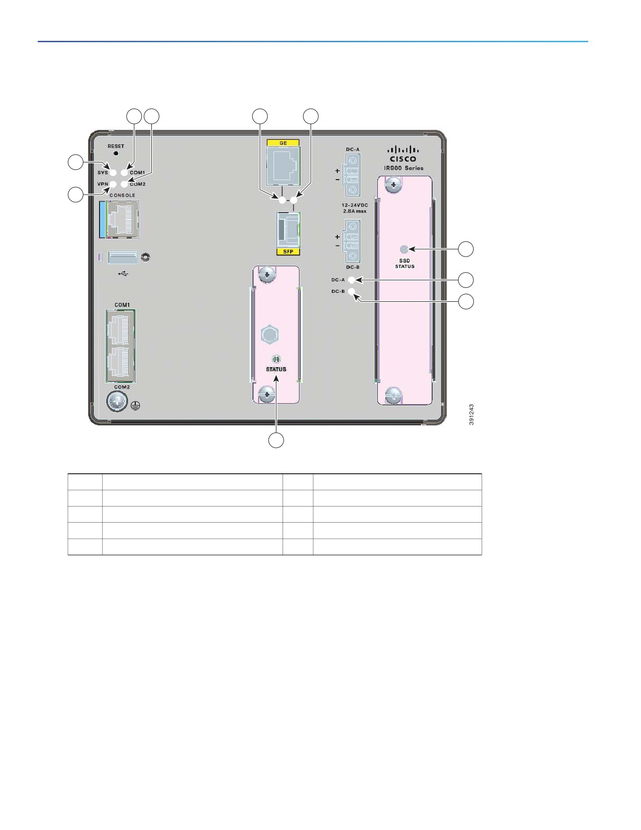
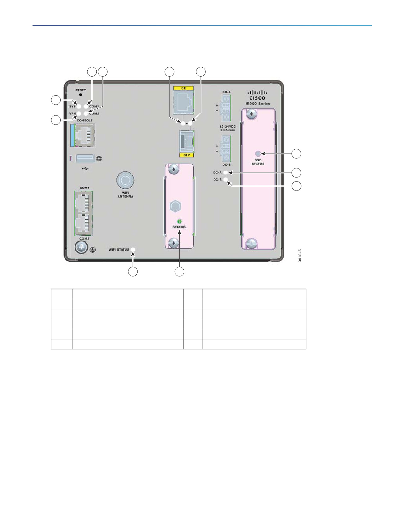
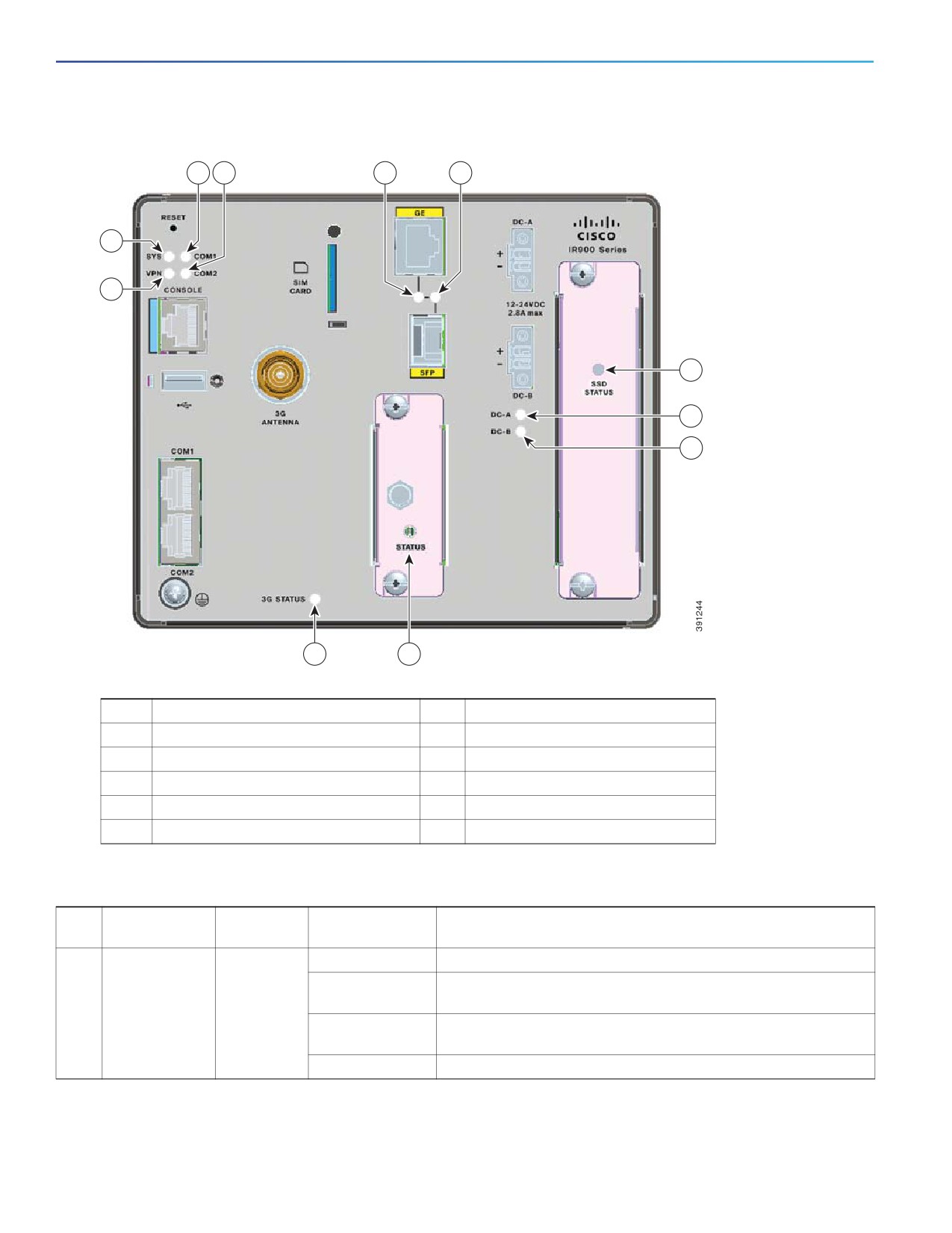
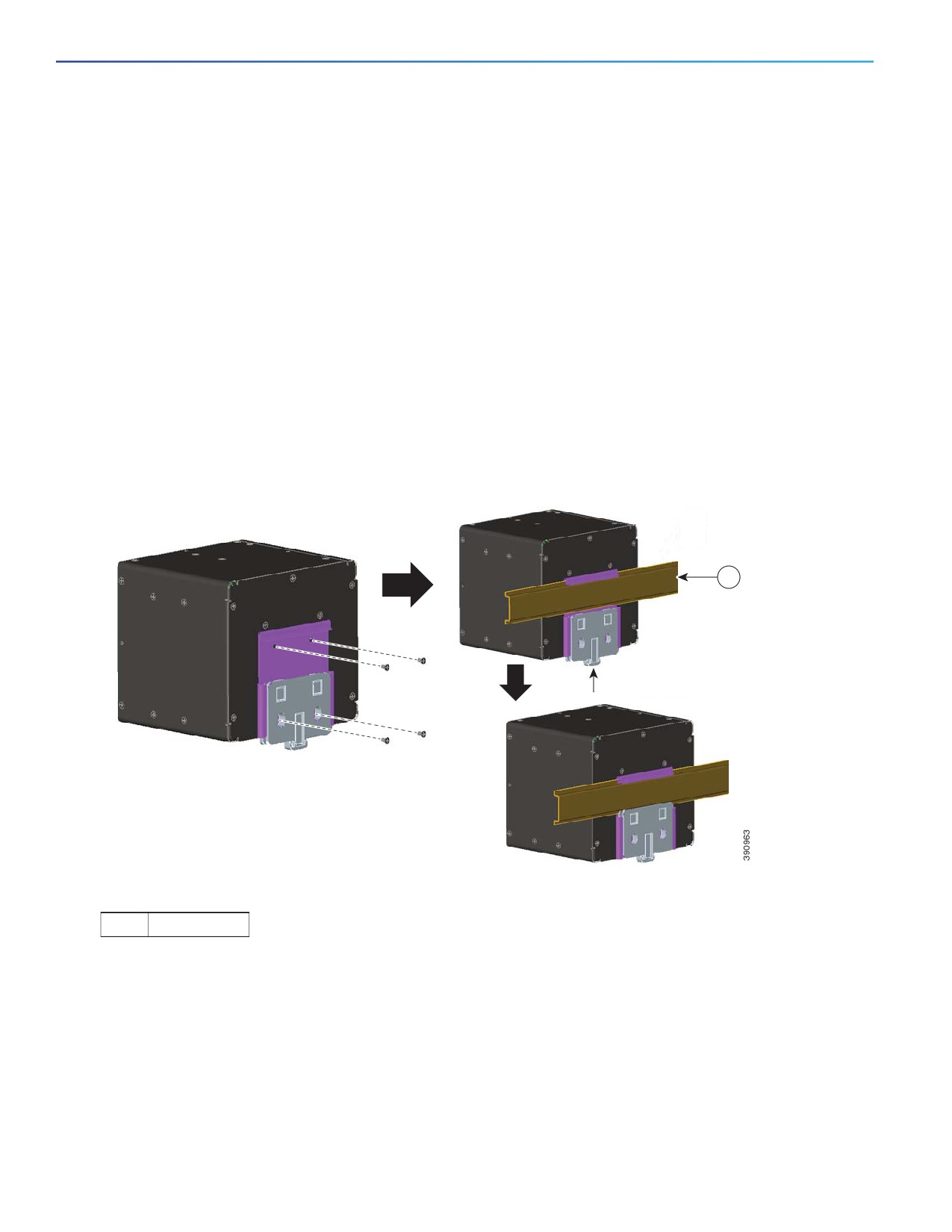
You can use the LEDs to monitor the router status, activity, and performance. Figure 5 to Figure 7 show the front panel
LEDs, and the following sections describe them.
All LEDs are visible through the web GUI management applications—the application for multiple routers and the device
CLI to configure and monitor the routers.
13
Front-Panel Description
Figure 5
LEDs of IR910-K9
3
4
8
9
1
2
12
10
11
7
1
SYS
8
GE-RJ-45
2
VPN
9
GE-SFP
3
COM1
10
DC-A
4
COM2
11
DC-B
7
Open slot status
12
SSD
14
Front-Panel Description
Figure 6
LEDs of IR910W-K9
3
4
8
9
1
2
12
10
11
5
7
1
SYS
8
GE-RJ-45
2
VPN
9
GE-SFP
3
COM1
10
DC-A
4
COM2
11
DC-B
5
Wi-Fi
12
SSD
7
Open slot status
15
Front-Panel Description
Figure 7
LEDs of IR910G-K9/IR910G-NA-K9
3
4
8
9
1
2
12
10
11
6
7
1
SYS
8
GE-RJ-45
2
VPN
9
GE-SFP
3
COM1
10
DC-A
4
COM2
11
DC-B
6
3G
12
SSD
7
Open slot status
Table 3
LED Definition
No.
LED
Single/Dual
Color
Meaning
Color
1
SYS
Dual
Off
System is not powered on or CPU has not completed boot up.
Blinking green
System is in the Power-on self-test (POST) stage, or the system
is getting IP address (IR910G-K9 only).
Solid green
System is operating normally, and IP address is attached
(IR910G-K9 only).
Solid red
System is not functioning properly.
16

Front-Panel Description
Table 3
LED Definition (continued)
No.
LED
Single/Dual
Color
Meaning
Color
2
VPN
Dual
Off
VPN is not set up.
Blinking green
VPN set up is in progress.
Solid green
VPN is operating normally.
Solid red
VPN is not functioning properly.
3
COM1
Dual
Off
COM port is enabled and configured as RS232 port.
Solid green
COM port is enabled and configured as RS485 port.
Solid red
Not defined.
4
COM2
Dual
Off
COM port is enabled and configured as RS232 port.
Solid green
COM port is enabled and configured as RS485 port.
Solid red
Not defined.
5
Wi-Fi
Single
Off
No activity.
Solid green
The connection between the gateway and base station has been
established.
Blinking green
Wi-Fi is transmitting data.
6
3G
Single
Off
No activity.
Solid green
Module is active (SIM card inserted).
7
Open slot
Single
Off
No link.
status
Solid green
Port link.
Blinking green
Transmitting or receiving data.
8
GE-RJ-45
Single
Off
No link.
Solid green
Port link, no activity.
Blinking green
Link is normal with activity.
9
GE-SFP
Single
Off
No link.
Solid green
Port link, no activity.
Blinking green
Link is normal with activity.
10
DC-A
Dual
Off
Power is not present on the circuit, or the system is not powered
up.
Solid green
Power is present on the associated circuit, and the gateway is
already booted up.
Solid red
Power is not present on the associated circuit, and the gateway is
configured for dual-input power.
11
DC-B
Dual
Off
Power is not present on the circuit, or the system is not powered
up.
Solid green
Power is present on the associated circuit, and the gateway is
already booted up.
Solid red
Power is not present on the associated circuit, and the gateway is
configured for dual-input power.
12
SSD
Single
Off
No power is provided to SSD.
Solid green
Power is provided to SSD.
Blinking green
SSD is being accessed.
17
Rear Panel Description
Power Status LED
The router can operate with one or two DC power sources. Each DC input has an associated LED that shows the status
of the corresponding DC input. If power is present on the circuit, the LED is green. If power is not present, the LED color
depends on the alarm configuration. If alarms are configured, the LED is red when power is not present; otherwise, the
LED is off.
If the router has dual power sources, the router draws power from the power source with the higher voltage. If one of
the DC sources fails, the alternate DC source powers the router, and the corresponding power status LED is green. The
power status for the failed DC source is either off or red, depending on the alarm configuration.
For information about the power LED colors during the power-on self-test (POST), see Verifying Router Operation.
Rear Panel Description
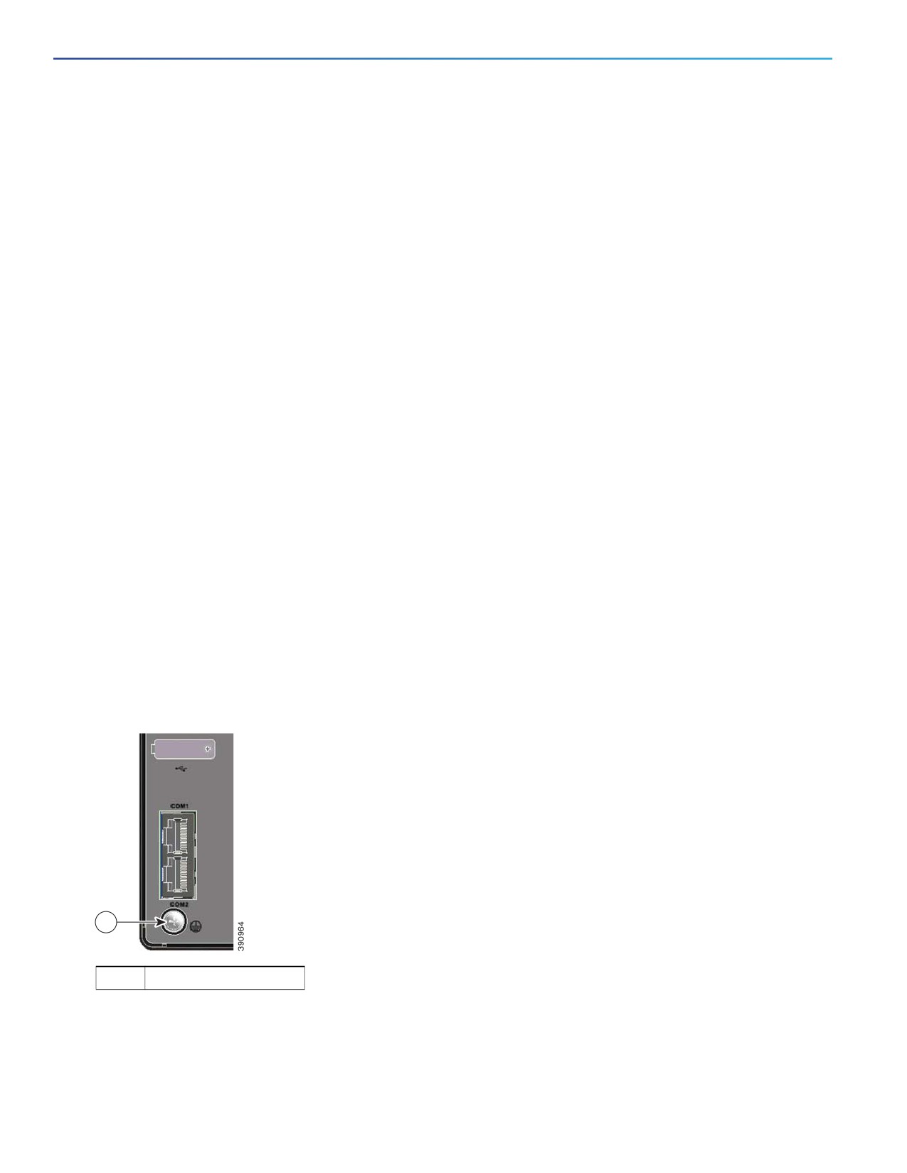
The rear panel of the router has a preinstalled DIN rail mount bracket for installation on a DIN rail. See Figure 8. The clip
on the edge of the mount bracket can be used to lock the DIN rail.
Figure 8
DIN Rail Mount Bracket on the Cisco 910 Industrial Router Rear Panel
1
Push clip to lock
the DIN Rail
1
DIN rail
Power Supply Adapter (Optional)
A 50 W AC input power supply (model number PWR-IE50W-AC) is available as an option for the router. The power supply
is designed to operate from source AC range of 85 to 264 VAC (115 VAC nominal at 60 Hz or 230 VAC nominal at 50 Hz)
and provides 24 VDC to the router.
18
Preparing for Installation
This chapter describes how to install the Cisco 910 Industrial Router and includes the procedures for basic router
installation and optional installation steps. The procedures you follow depend on your network environment and
requirements. This chapter contains the following sections:
Preparing for Installation, page 19
Verifying Router Operation, page 25
Installing the router, page 28
Installing the Antenna, page 29
Installing and Removing the Sensor Card, page 32
Installing and Removing the SSD Storage Card, page
33
Additional Router Connections, page 34
Connecting the Router to the Power Supply, page
36
Preparing for Installation
This section provides information about these topics:
Safety Recommendations, page 19
Safety with Electricity, page 20
Preventing Electrostatic Discharge Damage, page
20
Safety Warnings, page 20
CE Marking, page 22
Intended Use of the Equipment, page 22
National Restrictions, page 22
Antennas, page 23
Operating Frequency, page 23
Site Requirements, page 23
Other Guidelines, page 24
Verifying Package Contents, page 24
Safety Recommendations
To ensure general safety, follow these guidelines:
Keep the chassis area clear and dust-free during and after installation.
Keep tools and chassis components away from walk areas.
Do not wear loose clothing that could get caught in the chassis. Fasten your tie or scarf and roll up your sleeves.
19
Preparing for Installation
Wear safety glasses when working under conditions that might be hazardous to your eyes.
Do not perform any action that creates a hazard to people or makes the equipment unsafe.
Safety with Electricity
Follow these guidelines when working on equipment powered by electricity:
Read all the warnings in Safety Warnings.
Locate the emergency power-off switch for your installation location. If an electrical accident occurs, you can quickly
turn off the power.
Disconnect all power before:
— Installing or removing a chassis
— Working near power supplies
Look carefully for possible hazards in your work area, such as moist floors, ungrounded power extension cables,
frayed power cords, and missing safety grounds.
Do not work alone if hazardous conditions exist.
Never assume that power is disconnected from a circuit. Always check.
Never open the enclosure of the router’s internal power supply.
If an electrical accident occurs, proceed as follows:
— Use caution; do not become a victim yourself.
— Turn off power to the device.
— If possible, send another person to get medical aid. Otherwise, assess the victim’s condition and then call for
help.
— Determine if the person needs rescue breathing or external cardiac compressions; then take appropriate action.
Preventing Electrostatic Discharge Damage
Electrostatic discharge (ESD) can damage equipment and impair electrical circuitry. It may occur if electronic printed
circuit cards are improperly handled and may cause complete or intermittent failures. Always follow ESD prevention
procedures when removing and replacing modules:
Ensure that the router chassis is electrically connected to earth ground.
Wear an ESD-preventive wrist strap, ensuring that it makes good skin contact. Connect the clip to an unpainted
surface of the chassis frame to channel unwanted ESD voltages safely to ground. To guard against ESD damage and
shocks, the wrist strap and cord must operate effectively.
If no wrist strap is available, ground yourself by touching a metal part of the chassis.
Caution: For the safety of your equipment, periodically check the resistance value of the antistatic strap. It should
be between 1 and 10 megohms (Mohm).
Safety Warnings
This section contains important safety warnings for the installation and use of the router.
20
Preparing for Installation
Warning: IMPORTANT SAFETY INSTRUCTIONS
This warning symbol means danger. You are in a situation that could cause bodily injury. Before you work on any
equipment, be aware of the hazards involved with electrical circuitry and be familiar with standard practices for
preventing accidents. Use the statement number provided at the end of each warning to locate its translation in the
translated safety warnings that accompanied this device. Statement 1071
SAVE THESE INSTRUCTIONS
Warning: Before working on equipment that is connected to power lines, remove jewelry (including rings,
necklaces, and watches). Metal objects will heat up when connected to power and ground and can cause serious
burns or weld the metal object to the terminals. Statement 43
Warning: In order to comply with FCC radio frequency (RF) exposure limits, antennas should be located at a
minimum of 7.9 inches (20 cm) or more from the body of all persons. Statement 332
Warning: Do not work on the system or connect or disconnect cables during periods of lightning activity.
Statement 1001
Warning: Before performing any of the following procedures, ensure that power is removed from the DC circuit.
Statement 1003
Warning: Read the installation instructions before you connect the system to its power source. Statement 1004
Warning: This product relies on the building’s installation for short-circuit (overcurrent) protection. Ensure that the
protective device is rated not greater than: 20A. Statement 1005
Warning: This unit is intended for installation in restricted access areas. A restricted access area can be accessed
only through the use of a special tool, lock and key, or other means of security. Statement 1017
Warning: The plug-socket combination must be accessible at all times, because it serves as the main disconnecting
device. Statement 1019
Warning: This equipment must be grounded. Never defeat the ground conductor or operate the equipment in the
absence of a suitably installed ground conductor. Contact the appropriate electrical inspection authority or an
electrician if you are uncertain that suitable grounding is available. Statement 1024
Warning: This unit might have more than one power supply connection. All connections must be removed to
de-energize the unit. Statement 1028
Warning: Only trained and qualified personnel should be allowed to install, replace, or service this equipment.
Statement 1030
Warning: Ultimate disposal of this product should be handled according to all national laws and regulations.
Statement 1040
Warning: For connections outside the building where the equipment is installed, the following ports must be
connected through an approved network termination unit with integral circuit protection:
10/100/1000 Ethernet. Statement 1044
Warning: To prevent the system from overheating, do not operate it in an area that exceeds the maximum
recommended ambient temperature of: Statement 1047
140°F (60°C) (with SSD)
140°F (60°C) (without SSD card and in a sealed enclosure)
158°F (70°C) (without SSD card and in a vented enclosure)
Warning: Installation of the equipment must comply with local and national electrical codes. Statement 1074
Warning: To prevent airflow restriction, allow clearance around the ventilation openings to be at least:
3 inches (7.6 cm). Statement 1076
21
Preparing for Installation
Warning: Hot surface. Statement 1079
WARNING
HOT SURFACE
DO NOT TOUCH
Caution: This industrial router can only be accessed by service personnel or by users who have been instructed
about the reasons for the restrictions applied to the location. Access is through the use of a tool or lock and key, or
other means of security, and is controlled by the authority responsible for the location.
Caution: Be aware of the size and weight of the Cisco 910 Industrial Router when mounting. Ensure that the
mounting location has a stable flat surface and can safely support the weight of the device.
CE Marking
The following CE mark is affixed to the equipment and its packaging:
Intended Use of the Equipment
This product is to be used indoors or outdoors, but not for mobile and harsh shock.
National Restrictions
In the EU and other European Countries, the 2.4 bands have been made available for the use of wireless LANs.
This product is intended for indoor usage.
Note: Products that can operate in the 5150 MHz to 5350 MHz frequency band are restricted to indoor use only!
The following sections identify countries having additional requirements or restrictions.
Denmark
In Denmark, the band 5150 - 5350 MHz is also allowed for outdoor usage.
I Danmark må frekvensbåndet 5150 - 5350 også anvendes udendørs.
Italy
This product meets the National Radio Interface and the requirements specified in the National Frequency Allocation
Table for Italy. Unless this wireless LAN product is operating within the boundaries of the owner’s property, its use
requires a “general authorization”. Please check
Questo prodotto è conforme alla specifiche di Interfaccia Radio Nazionali e rispetta il Piano Nazionale di ripartizione delle
frequenze in Italia. Se non viene installato all’interno del proprio fondo, l’utilizzo di prodotti Wireless LAN richiede una
“Autorizzazione Generale”. Consultare
22

Preparing for Installation
Latvia
The outdoor usage of the 2.4 GHz band requires an authorization from the Electronic Communications Office. Please
2,4 GHz frekvenču joslas izmantošanai ārpus telpām nepieciešama atļauja no Elektronisko sakaru direkcijas. Vairāk
informācijas: http://www.esd.lv.
Note: Although Norway, Switzerland, Liechtenstein and Turkey are not EU member states, the EU Directive 1999/5/EC
has also been implemented in those countries.
Antennas
IR910W-K9, IR910G-K9, IR910G-NA-K9, and LoRa cards are equipped with antennas.
Operating Frequency
The operating frequency in a Wireless LAN is determined by the access point. As such, it is important that the access
point is correctly configured to meet the local regulations.
Operating Frequency Range of Cisco LoRa Card
Table 1 listed the operating frequency ranges of the Cisco 433MHz and 868MHz LoRa cards.
Caution: Do not exceed the limit of allowed operating frequency range when you are using a Cisco LoRa card.
Table 1
Operating Frequency of LoRa Card
Cisco LoRa Card
Operating Frequency Range
Compliance
Effective Radiated Power
Region
(e.r.p)
Cisco 433 MHz LoRa card
433.05—434.79 MHz
Singapore and EU
<=10 mW (e.r.p)
Cisco 868 MHz LoRa card
863—870 MHz
EU
<=500 mW (e.r.p)
Site Requirements
This section describes the requirements your site must meet for safe installation and operation of your router. Ensure that
the site is properly prepared before beginning installation. If you are experiencing shutdowns or unusually high errors
with your existing equipment, this section can also help you isolate the cause of failures and prevent future problems.
Environmental Requirements
The location of your router is an important consideration for proper operation. Equipment placed too close together,
inadequate ventilation, and inaccessible panels may cause malfunctions and shutdowns, and make maintenance difficult.
If you are currently experiencing shutdowns or an unusually high number of errors with your existing equipment, these
precautions and recommendations may help you isolate the cause of failure and prevent future problems.
Always follow ESD-prevention procedures described in Preventing Electrostatic Discharge Damage to avoid damage
to equipment. Damage from static discharge can cause immediate or intermittent equipment failure.
Ensure that all empty module slots and have filler panels installed.
23
Preparing for Installation
When other equipment is installed on or connected to the router, try operating the router by itself, if possible. Power
off other equipment (such as USB devices and installed third-party modules) to allow the router a maximum of
cooling air and clean power.
Other Guidelines
When determining where to place the router, observe these guidelines:
Before installing the router, first verify that the router is operational by powering it on and running POST. Follow the
procedures in Verifying Router Operation.
Operating environment is within the ranges listed in the Technical Specifications for the Cisco 910 Industrial Router.
Clearance to front panels meets these conditions:
— Front-panel LEDs can be easily read.
— Access to ports is sufficient for unrestricted cabling.
— Front-panel direct current (DC) power connector is within reach of the connection to the DC power source.
Airflow around the router and through the vents is unrestricted. To prevent the router from overheating, there must
be a minimum clearance of 3 in. (76 mm).
Temperature surrounding the unit does not exceed:
—
140°F (60°C) (with SSD)
—
140°F (60°C) (without SSD card and in a sealed enclosure)
—
158°F (70°C) (without SSD card and in a vented enclosure)
Cabling is away from sources of electrical noise, such as radios, power lines, and fluorescent lighting fixtures.
Verifying Package Contents
Carefully remove the contents from the shipping container, and check each item for damage. If any item is missing or
damaged, contact your Cisco representative or reseller for support. Return all packing materials to the shipping container
and save them.
The router is shipped with these items:
Printed documentations include:
— Cisco 910 Industrial Router Quick Start Guide
— Pointer Card for the Cisco 910 Industrial Router
Two DC power connectors
DIN mounting kit, preinstalled at the rear of the device
3G antenna (only for IR910G-K9 and IR910G-NA-K9)
Wi-Fi antenna (only for IR910W-K9)
3G or Wi-Fi antenna wire clip (only for IR910G-K9, IR910G-NA-K9, and IR910W-K9)
The following items can be ordered separately and are not included by default with the chassis:
External storage (model number: ACC-IR910-S16)—SSD media with 16 GB capacity
24
Verifying Router Operation
IP55 enclosure and wall or pole mount kit (model number: ACC-IR910-H-M=)—IP55-certified dust-and-water
protection for outdoor usage by wall or pole mounting.
Open slot modular mount bracket (model number: ACC-IR910-W-M=)—This mount bracket is orderable strictly by
partners who builds sensor module card PCBA and need this bracket for faceplate assembly.
Verifying Router Operation
Before installing the router in its final location, power on the router, and verify that the router passes the power-on
self-test (POST).
These sections describe the steps required to connect a PC or terminal to the router console port, to power on the router,
and to observe POST results:
Connecting a PC or a Terminal to the Console Port
Verifying Router Operation
Connecting a PC or a Terminal to the Console Port
You can access the CLI by connecting the console port to your PC or workstation and accessing the router through a
terminal emulation program.
To connect a PC to the console port, use an RJ-45-to-DB-9 adapter cable. To connect a terminal to the console port,
provide an RJ-45-to-DB-25 female DTE adapter.
The PC or terminal must support VT100 terminal emulation. The terminal-emulation software—frequently, a PC
application such as HyperTerminal or Procomm Plus—makes communication between the router and your PC or terminal
possible.
Follow these steps to connect the PC or terminal to the router:
1. Using an RJ-45-to-DB-9 adapter cable, insert the RJ-45 connector into the console port on the front panel of the
router and connect the other end to the PC or terminal port.
2. Start the terminal-emulation program on the PC or terminal.
3. Configure the baud rate and data format of the PC or terminal to match these console-port default characteristics:
—
115200 bits per second
—
8 data bits
—
1 stop bit
— No parity
— None (flow control)
After you get access to the router, you can change the port baud rate. See the Cisco 910 Industrial Router Software
Configuration Guide for instructions.
1. Connect the power of the router. The PC or terminal displays the bootloader sequence.
2. Press Enter to display the setup prompt.
25
Verifying Router Operation
Connecting the Protective Ground and DC Power
These sections describe the steps required to connect a protective ground and DC power to the router:
Grounding the Router, page 26
Wiring the DC Power Source, page 26
Attach the Power Connector to the Router, page 28
Locate the power connector in the router accessory kit.
Grounding the Router
To ground the router to earth ground by using the ground screw, follow these steps. Make sure you follow the grounding
requirements at your site.
Warning: This equipment must be grounded. Never defeat the ground conductor or operate the equipment in the
absence of a suitably installed ground conductor. Contact the appropriate electrical inspection authority or an
electrician if you are uncertain that suitable grounding is available. Statement 1024
Warning: This equipment is intended to be grounded to comply with emission and immunity requirements. Ensure
that the router functional ground lug is connected to earth ground during normal use. Statement 1064
1. Use a standard Phillips screwdriver or a ratcheting torque screwdriver with a Phillips head to remove the ground
screw from the front panel of the router. Store the ground screw for later use.
2. Insert the ground wire into the ring terminal lug, and using a crimping tool, crimp the ring terminal to the wire.
3. Slide the ground screw through the ring terminal.
4. Insert the ground screw into the functional ground screw opening on the front panel.
5. Tighten the ground screw and ring terminal lug to the router front panel.
6. Attach and secure the other end of the ground wire to a grounded pole or a wall.
Figure 1
Grounding the Device
1
1
Grounding screw
Wiring the DC Power Source
Read these warnings before wiring the DC power source:
26
Verifying Router Operation
Warning: A readily accessible two-poled disconnect device must be incorporated in the fixed wiring.
Statement 1022
Warning: This product relies on the building’s installation for short-circuit (overcurrent) protection. Ensure that the
protective device is rated not greater than:
5A. Statement 1005
Warning: Installation of the equipment must comply with local and national electrical codes. Statement 1074
Warning: Before performing any of the following procedures, ensure that power is removed from the DC circuit.
Statement 1003
Warning: Only trained and qualified personnel should be allowed to install, replace, or service this equipment.
Statement 1030
Caution: You must connect the router only to a DC input power source that has an input supply voltage between
12 and 24 VDC. If the supply voltage is not in this range, the router might not operate properly or get damaged.
The Cisco 910 Industrial Router supports dual DC power inputs. The voltage range should be from 12 VDC to 24 VDC.
When the device is installed in an environment requiring AC inputs, use the optional AC power adapter described in
Verifying Package Contents.
To wire the router to a DC input power source, follow these steps:
1. Locate the power connector.
2. Identify the positive and return DC power connections on the front panel of the router. The positive DC power
connection is labeled +, and the return is the adjacent connection labeled -.
3. Measure two strands of twisted-pair copper wire (18-to-20 AWG) long enough to connect to the DC power source.
4. Using an 18-gauge wire-stripping tool, strip each of the two twisted pair of wires coming from each DC input power
source to 0.25 inch (6.3 mm) ± 0.02 inch (0.5 mm). Do not strip more than 0.27 inch (6.8 mm) of insulation from the
wire. Stripping more than the recommended amount of wire can lead to exposed wire from the power connector
after installation.
5. Insert the exposed part of the positive wire into the connection labeled + and the exposed part of the return wire
into the connection labeled -. Make sure that you cannot see any wire lead. Only wire with insulation should extend
from the connector.
Warning: An exposed wire lead from a DC-input power source can conduct harmful levels of electricity. Be sure that
no exposed portion of the DC-input power source wire extends from the power and relay connector. Statement 122
6. Use a ratcheting torque flathead screwdriver to torque the power connector captive screws (above the installed wire
leads) to 2.2 in-lb (0.25 Nm).
Caution: Do not over-torque the power connector captive screws. The torque should not exceed 2.2 in-lb
(0.25 Nm).
7. Connect the other end of the positive wire (the one connected to +) to the positive terminal on the DC power source,
and connect the other end of the return wire (the one connected to -) to the return terminal on the DC power source.
When you are testing the router, one power connection is sufficient. If you are installing the router and are using a second
power source, repeat 4. through 7. using a second power and relay connector.
8. Go to Verifying Router Operation.
27
Installing the router
Attach the Power Connector to the Router
To attach the power connectors to the front panel of the router, follow these steps:
1. Insert the power connector jack into the DC-A receptacle on the front panel of the router.
2. Use a ratcheting torque flathead screwdriver to tighten the captive screws on the sides of the power connector.
When you are testing the router, one power source is sufficient. If you are installing the router and are using a second
power source, repeat this procedure for the second power connector (DC-B), which is installed just below the primary
power connector (DC-A).
When you are installing the router, secure the wires coming from the power connector so that they cannot be disturbed
by casual contact, for example, use tie wraps to secure the wires to the rack.
Running POST
When the router powers on, it automatically initiates a POST, which runs a series of tests that verify if the router is
functioning properly and ensures that it is ready to install. To test the router, follow these steps:
Applying Power to the Router, page 28
Verify POST Results, page 28
Disconnect Power, page 28
Applying Power to the Router
To apply power to the router, connect it directly to a DC power source. The power LED (DC-A or DC-B) turns on and the
router powers on immediately.
Verify POST Results
When you power on the router, it automatically begins POST. All LEDs are off for a few seconds. The system LED
continues to blink green as the software image verifies the basic functionality of the system initialization. Assuming all
the tests are passed, the SYS LED turns solid green. If the POST fails, the SYS LED turns red.
Note: POST failures are usually fatal. Call Cisco technical service representative immediately if your router does not pass
POST. See Obtaining Documentation and Submitting a Service Request.
Disconnect Power
After successfully running POST, follow these steps:
1. Disconnect the cables.
2. Decide where you want to install the router.
Installing the router
This section describes how to install the router:
Installing the Router on a DIN Rail
Installing the Router on a Wall or Pole
To prevent the router from overheating, ensure a minimum clearance of 3 in. (76 mm).
28
Installing the Antenna
Installing the Router on a DIN Rail
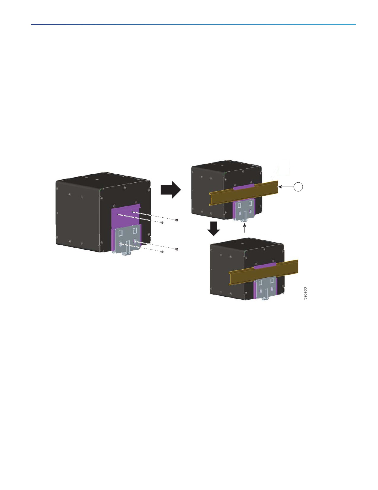
For indoor use, DIN rail mount is the default mounting solution. The router ships with a DIN mount bracket on the rear
panel for the mounting on a standard 7.5-mm DIN rail.
Note: The DIN mount bracket is already installed with four screws on the rear panel of the device when shipped.
To mount the router to a DIN rail, follow these steps:
1. Position the DIN mount bracket directly in front of the DIN rail, making sure that the DIN rail fits in the space on the
DIN mount bracket. See Figure 2.
Figure 2
Mount to a DIN Rail
1
Push clip to lock
the DIN Rail
2. Push the clip at the bottom of the DIN mount bracket to lock the DIN rail.
3. After the router is mounted on the DIN rail, connect the power.
Installing the Router on a Wall or Pole
For outdoor use, install the chassis of the router into an IP55-certified dust-and-water protection enclosure. After this,
install the assembled IP55 case to a wall or a pole.
For detailed installation procedures of assembling the IP55 case and mounting the device to a wall or pole, see the
Mounting Kit Assembly Guide for the Cisco 910 Industrial Router.
Installing the Antenna
This section describes the installation of antenna for indoor and outdoor use.
29
Installing the Antenna
Indoor Antenna Installation
Follow these steps to install a 3G antenna for IR910G-K9 or IR910G-NA-K9, or a Wi-Fi antenna for IR910W-K9, for
indoor use.
1. Attach one end of the cable to the antenna, and the other end to the Wi-Fi or 3G antenna connector on the panel.
Note: The 3G antenna has a TNC type connector with a black heat shrink tube. The 868MHz LoRa card antenna has
an SMA type connector with a black heat shrink tube. The 433MHz LoRa card antenna has an SMA type connector
with a white heat shrink tube.
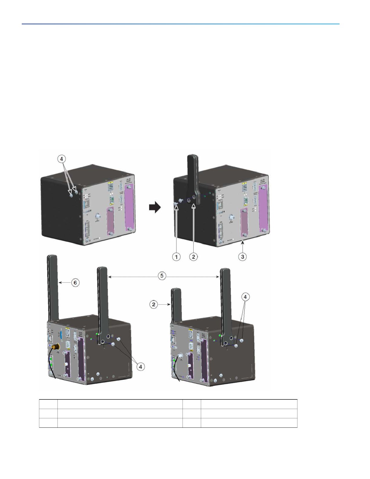
2. Use two M3 screws to fix the antenna, as shown in Figure 3.
Figure 3
Fixing the Antenna
1
Fix the antenna with two M3 screws
4
M3 screws
2
WiFi antenna
5
Sensor card antenna
3
Chassis
6
3G antenna
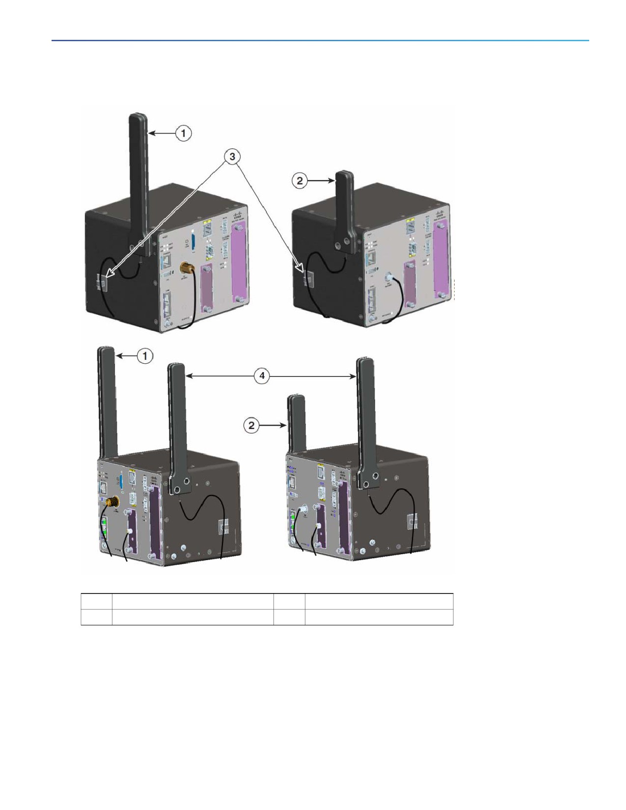
3. Place the antenna clip in the approximate location, as shown in Figure 4.
30
Installing the Antenna
Figure 4
Positioning the Antenna Clip
1
3G antenna
3
Wire clip
2
WiFi antenna
4
Sensor card antenna
4. Use the clip to fix the cable.
Antenna Installation with IP55 Enclosure
For information about the installation of Wi-Fi or 3G antenna when the router is mounted to a wall or a pole with the IP55
enclosure, see the Mounting Kit Assembly Guide for the Cisco 910 Industrial Router.
31
Installing and Removing the Sensor Card
Installing and Removing the Sensor Card
This section describes the installation and removal of the sensor card.
Assembling the Sensor Card to the Carrier, page 32
Installing the Sensor Card Module into the Router, page 33
Removing the Sensor Card Module From the Router, page 33
Note: If you have ordered a LoRa card from Cisco together with the router, the LoRa card will be preinstalled into the
router.
Assembling the Sensor Card to the Carrier
If you have ordered the sensor card from Cisco together with your chassis, the sensor card module will be preinstalled
into the router. If you use your own sensor card, you can order a sensor card carrier to assemble your sensor card into it.
To assemble your own sensor card into the sensor card carrier, follow these steps:
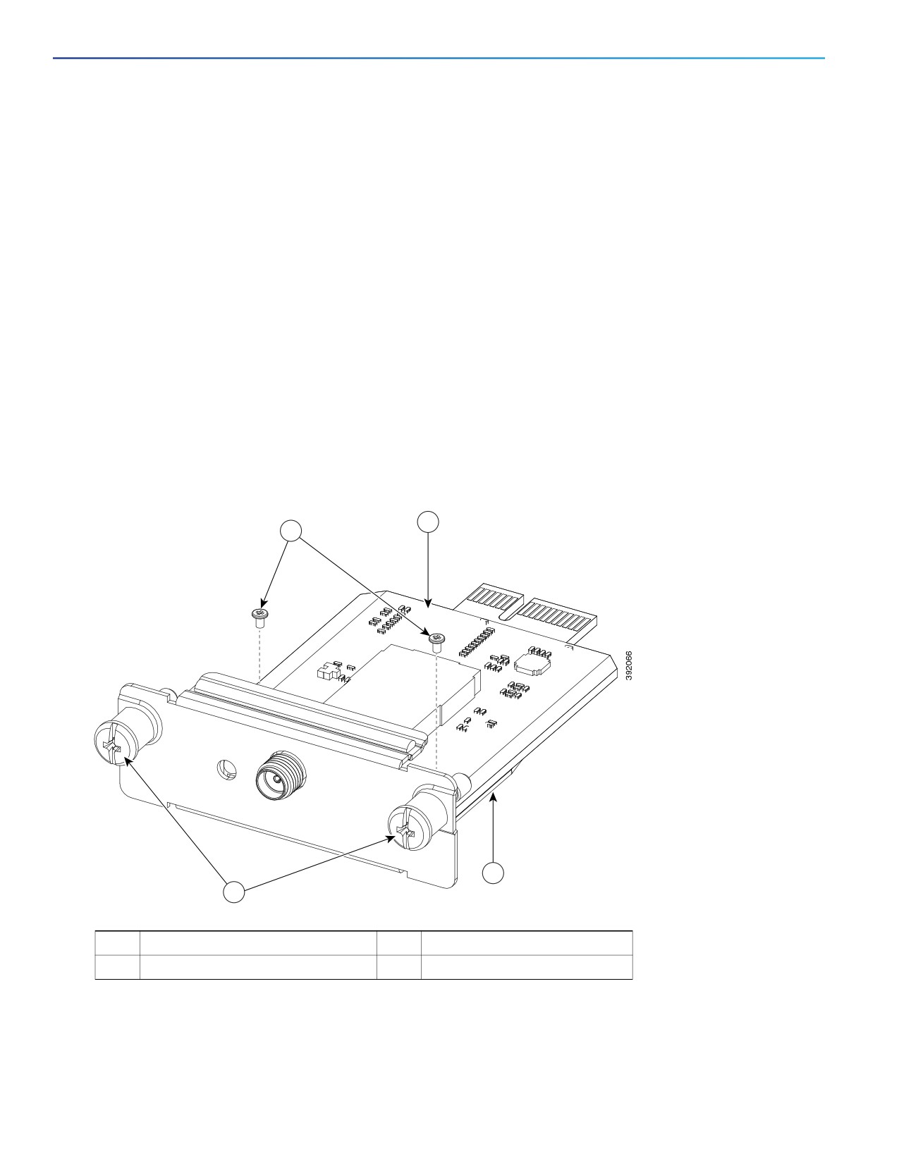
1. Put the sensor card onto the plate of the sensor card carrier, as shown in Figure 5.
Figure 5
Assembling Sensor Card to the Carrier
3
1
4
2
1
M2 x 4 mm screws
3
Sensor card
2
Captive screws
4
Sensor card carrier plate
2. Align the two boles near the top of the sensor card with the two bores on the carrier plate.
3. Thread an M2 screw through each bore in the sensor card and down into the corresponding bore in the sensor card
carrier plate.
32
Installing and Removing the SSD Storage Card
4. Tighten each screw inside the bore to fix the sensor card to the carrier.
Installing the Sensor Card Module into the Router
Follow these steps to install the sensor card into the open slot in the Cisco 910 Industrial Router:
1. Before you install (or remove) the sensor card from the router, power down the router first.
2. Insert the sensor card into the open slot.
3. Using a screwdriver, secure the two captive screws into place.
Removing the Sensor Card Module From the Router
Follow these steps to remove the sensor card from the open slot in the Cisco 910 Industrial Router:
1. Using a screwdriver, loosen the two captive screws on the open slot sensor card carrier.
2. Gently pull the sensor card out of the open slot.
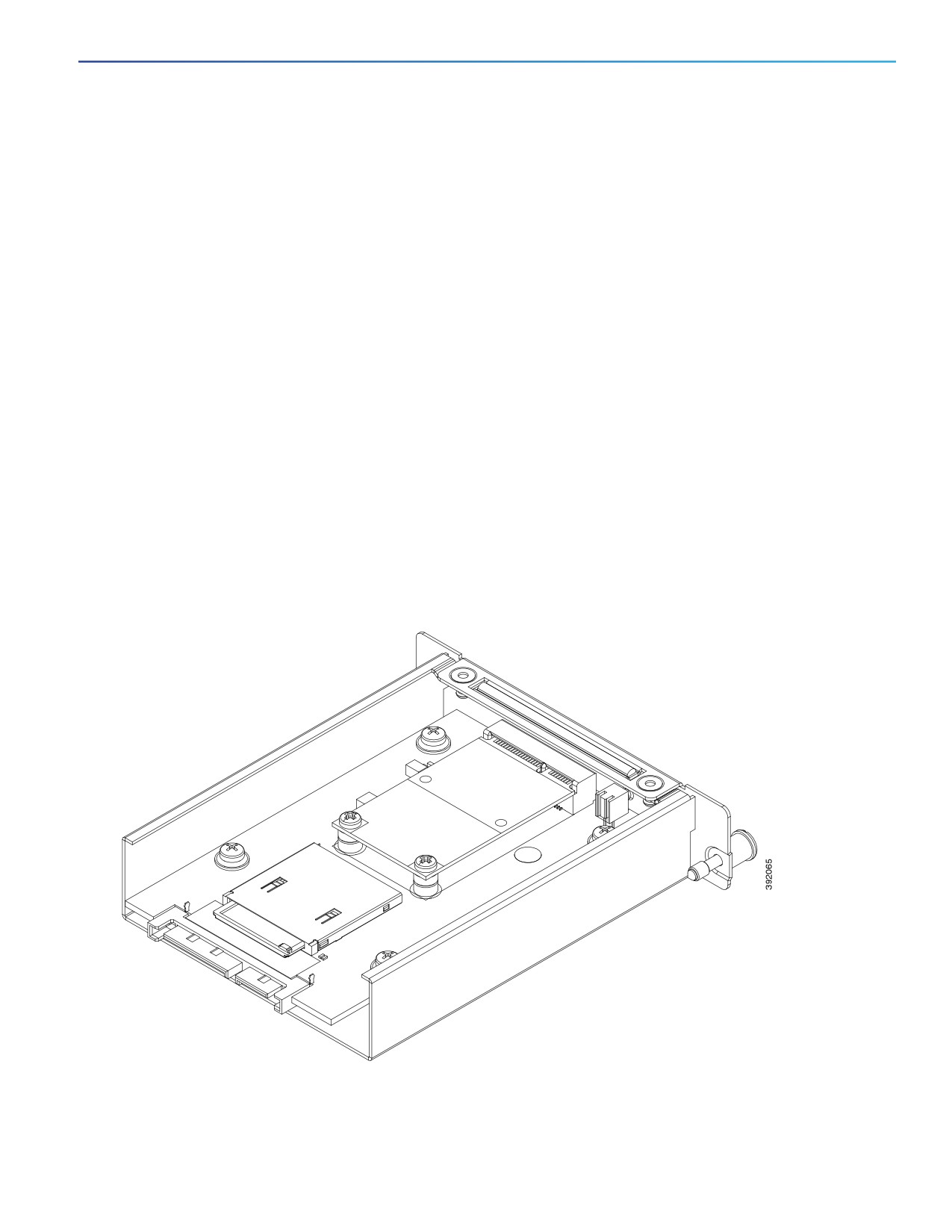
Installing and Removing the SSD Storage Card
This section describes the installation and removal of the SSD storage card.
Figure 6 shows an SSD storage card assembled into the SSD carrier.
Figure 6
SSD Card Module
If you have ordered the SSD storage card together with your chassis, it will be preinstalled into the router.
33
Additional Router Connections
Installing the SSD Storage Card Into the Router, page 34
Removing the SSD Storage Card From the Router, page 34
Installing the SSD Storage Card Into the Router
Follow these steps to install the SSD storage card into the slot in the Cisco 910 Industrial Router:
1. Before you install (or remove) the SSD storage card from the router, power down the router first.
2. Insert the SSD storage card into the slot.
3. Using a screwdriver, secure the two captive screws into place.
Removing the SSD Storage Card From the Router
Follow these steps to remove the SSD storage card from the slot in the Cisco 910 Industrial Router:
1. Using a screwdriver, loosen the two captive screws on the SSD storage card carrier.
2. Gently pull the SSD storage card out of the slot.
Additional Router Connections
This section provides information about making other, additional router cable connections. Follow the procedures in this
section based on your network configuration and requirements. This section contains information about these
procedures:
Connecting a Serial Port, page 34
Connecting a USB Port, page 35
Connecting an SFP Port, page 35
Connecting the Gigabit Ethernet Port, page 36
Connecting a Serial Port
See Figure 1 for the serial port location of the router.
Before you connect a device to a serial port, you need to know the following:
Type of device, data terminal equipment (DTE) or data communications equipment (DCE), that you are connecting
to the synchronous serial interface
Type of connector, male or female, required to connect to the device
Signaling standard required by the device
You must provide or purchase separately the correct serial cable. The cable does not ship with the router. Contact
your Cisco reseller to purchase the correct cable from Cisco.
The RS232 interface of the router operates as a DCE; any connection to this interface must be as a DTE.
You can connect a device to this port while the router is operating normally.
The serial ports are labeled COM1 and COM2.
34
Additional Router Connections
Connecting a USB Port
See Figure 1 for the USB port location.
You can connect an optional USB device to the USB port, which will provide power to the USB device. You can also
connect a USB device that is powered by an external power source, such as an AC adapter or batteries.
Before you connect a USB port, you need to know the following:
You can connect the USB device to the port while the router is operating normally.
Depending on the USB device you connect to the port, you might require a USB extension cable to connect the USB
device to the port.
To prevent the connected USB device from being stolen or accidentally removed, secure any connected USB device
with a locking mechanism designed for this purpose.
Connecting an SFP Port
See Figure 1 for the SFP port location.
Small Form-Factor Pluggable (SFP) modules are transceiver devices that plug into the router SFP connectors. The
transceiver connects the electrical circuitry of the module with the optical network.
The SFP module used on the port must match the wavelength specifications on the other end of the cable, and the cable
must not exceed the stipulated cable length for reliable communications.
Use only Cisco SFP transceiver modules with the router. Each SFP transceiver module supports the Cisco Quality
Identification (ID) feature that allows a Cisco switch or router to identify and validate that the transceiver module is
certified and tested by Cisco.
For detailed instructions on installing, removing, and cabling the SFP transceivers, see the corresponding SFP module
documentation.
Warning: Class 1 laser product. Statement 1008
Caution: Do not remove the dust plugs from the fiber-optic SFP module port or the rubber caps from the fiber-optic
cable until you are ready to connect the cable. The plugs and caps protect the SFP module ports and cables from
contamination and ambient light.
Caution: You are not recommended to install or remove the SFP module while the fiber-optic cable is attached to it,
because of potential damage to the cables, to the cable connector, or to the optical interfaces in the SFP module.
Disconnect the fiber-optic cable before you remove or install an SFP module.
Materials and Tools Required
You must provide these tools and materials to install an SFP transceiver module:
Wrist strap or other personal grounding device to prevent ESD occurrences.
Antistatic mat or antistatic foam to set the transceiver on.
Fiber-optic end-face cleaning tools and inspection equipment. For complete information on inspecting and cleaning
fiber-optic connections, see white-paper at:
Before you connect an SFP port, you need to know the following:
You can connect an SFP module to the port while the router is operating normally.
35
Connecting the Router to the Power Supply
When installing or removing an SFP module, observe these guidelines:
— Removing and installing an SFP module can shorten its useful life. Do not remove and insert any module more
often than is absolutely necessary.
— To prevent ESD damage, follow your normal board and component handling procedures when connecting
cables to the switch and other devices.
This procedure describes how to install an SFP module. which is inserted into the SFP port shown in Figure 1.
1. Attach an ESD-preventive wrist strap to your wrist and to a bare metal surface.
2. For a fiber-optic SFP module, remove the dust plug, and store it in a clean location for reuse.
3. Position the SFP transceiver module in front of the socket opening, and insert the SFP into the socket until you feel
the connector latch into place.
4. Remove the dust plug from the network interface cable LC connector.
5. Inspect and clean the LC connector's fiber-optic end-face.
6. Attach the network interface cable connector to the SFP transceiver module.
Caution: We strongly recommend that you do not install or remove the SFP transceiver with fiber-optic cables
attached to it because of the potential damage to the cables, the cable connector, or the optical interfaces in the
SFP module. Disconnect all cables before removing or installing an SFP transceiver.
Connecting the Gigabit Ethernet Port
See Figure 1 for the Gigabit Ethernet port location.
The router has a Gigabit Ethernet port for connecting the router to an Ethernet network through a hub or switch.
The Gigabit Ethernet port has identical label to the SFP ports because the SFP port shares physical port with the Gigabit
Ethernet port. For detailed information about how to use both these ports, see the Combo Port (GE and SFP).
Warning: Do not work on the system or connect or disconnect cables during periods of lightning activity. Statement
1001
Connecting the Router to the Power Supply
The Cisco 910 Industrial Router can be used with an optional AC input power supply (model number PWR-IE50W-AC).
This section describes the steps required to connect the router to the AC input power supply.
36

Technical Specifications for the Cisco 910 Industrial Router
Technical Specifications for the
Cisco 910 Industrial Router
Table 1 lists the technical specifications for the Cisco 910 Industrial Router.
Table 1
Cisco 910 Industrial Router Environmental and Physical Specifications
Environmental Ranges
Operating temperature
With SSD
32 to 140°F (0 to 60°C)
Without SSD card and in a sealed
-40 to 140°F (-40 to 60°C)
enclosure
Without SSD card and in a vented
-40 to 158°F (-40 to 70°C)
enclosure
Storage temperature
-40 to 185°F (-40 to 85°C)
Relative humidity
Operating and storage: 5 to 95% (noncondensing)
Operating altitude
0 to 15000 ft (0 to 4572 m)
Storage altitude
Up to 15000 ft (4572 m)
IP grade
Without IP55 enclosure
IP30
With IP55 enclosure
IP55
Physical Specifications
Weight
Without IP55 enclosure and sensor
5.07 lbs (2.3 kg)
communication card
With IP55 enclosure and sensor
7.94 lbs (3.6 kg)
communication card
Dimensions (H x W x D)
130 mm x 158 mm x 129 mm (5.1 in. x 6.2 in. x 5.08 in.) without IP55 enclosure, front
of DIN rail
130 mm x 158 mm x 137 mm (5.1 in. x 6.2 in. x 5.38 in.) without IP55 enclosure, back
of DIN rail
301mm x 243mm x 152mm (11.85 in. x 9.56 in. x 5.98 in.), with IP55 enclosure
37