LENZE Embedded Line (EL), Command Station (CS), Cabinet PC (CPC), L-force Controller 3241 C. System structure and configuration (2013)
EDSIPCx7
.N+_
L−force Controls
System Manual
Industrial PC
Embedded Line (EL), Command Station (CS), Cabinet PC (CPC), L−force
Controller 3241 C
System structure and configuration
l
Contents
i
1
About this documentation
4
1.1
Document history
4
1.2
Conventions used
5
1.3
Terminology used
5
1.4
Notes used
6
2
Safety instructions
7
2.1
General safety information
7
3
Product description
10
3.1
Application as directed
10
3.2
"Industrial PC" system
11
3.3
Overview of designs
14
3.3.1
Embedded Line
15
3.3.2
Command Station
16
3.3.3
Cabinet PC
17
3.4
Embedded Line (EL, MP) design
18
3.5
Command Station (CS) design
20
3.6
Cabinet PC (CPC) design
23
3.6.1
3241 C
23
3.6.2
CPC 2800
25
3.6.3
CPC 5100
26
3.6.4
CPC 9100
27
3.7
Options
28
3.7.1
Overview
28
3.7.2
ACU UPS control unit
28
3.8
Accessories
29
3.8.1
Overview
29
3.9
Software
30
3.9.1
Operating system (accessories)
30
3.9.2
Other software types
30
3.9.3
Fan monitoring with "Smart Cool" and "FAN Service" (option)
31
4
Index
32
l
3
1
About this documentation
Document history
1
About this documentation
Contents
This documentation provides you with information about the intended use of the
Industrial PC.
The present manual is part of the "PC−based automation" manual collection which you can
find on the DVDs of the same name.
Target group
This documentation is directed at qualified skilled personnel according to IEC 60364.
Qualified skilled personnel are persons who have the required qualifications to carry out
all activities involved in installing, mounting, commissioning, and operating the product.
Validity
These instructions are valid for
ƒ Embedded Line EL 1800 − EL 9800 (TC)
ƒ Monitor Panel MP 800 − 9000 DVI
ƒ Command Station CS 5800 − 9800 (TC)
ƒ Command Station CS 5000 − 9000 DVI
ƒ Cabinet PC CPC 2800, CPC 5100, CPC 9100
ƒ Cabinet PC 3241 C
1.1
Document history
Material number
Version
Description
.N+_
4.1
11/2013
TD29
Description of MC cards moved in separate
operating instruction
13433000
4.0
03/2013
TD29
General revision
13370131
3.0
02/2011
TD29
Amended by description of MC−ISI communication
card
13348653
2.0
10/2010
TD31
Change of generation from x700 series to x800
series
13300002
1.0
06/2009
TD14
First edition
I Tip!
Information and auxiliary devices related to the Lenze products can be found
in the download area at
4
l
EDSIPCx7 EN 4.1
About this documentation
1
Conventions used
1.2
Conventions used
This documentation uses the following conventions to distinguish between different
types of information:
Spelling of numbers
Decimal separator
Point
In general, the decimal point is used.
For instance: 1234.56
Text
Program name
» «
PC software
For example: »Engineer«, »Global Drive
Control« (GDC)
Icons
Page reference
^
Reference to another page with additional
information
For instance: ^ 16 = see page 16
Documentation reference
,
Reference to another documentation with
additional information
For example: , EDKxxx = see
documentation EDKxxx
1.3
Terminology used
Term
Meaning
IPC
Industrial PC
CPC
Cabinet PC; control cabinet PC with decentralised
display/operating unit (MP, Thin Client)
CS
Command Station; stand−alone operator station
EL
Embedded Line PC; for installation in control cabinets, machine
panelling, or other mounting cutouts
MP
Monitor panel; external display
Thin Client
Device for representing and operating applications which are
located on a remote host computer (e.g. CPC).
PLC
Programmable Logic Controller
l
5
1
About this documentation
Notes used
1.4
Notes used
The following pictographs and signal words are used in this documentation to indicate
dangers and important information:
Safety instructions
Structure of safety instructions:
} Danger!
(characterises the type and severity of danger)
Note
(describes the danger and gives information about how to prevent dangerous
situations)
Pictograph and signal word
Meaning
Danger of personal injury through dangerous electrical voltage.
Reference to an imminent danger that may result in death or
{ Danger!
serious personal injury if the corresponding measures are not
taken.
Danger of personal injury through a general source of danger.
Reference to an imminent danger that may result in death or
} Danger!
serious personal injury if the corresponding measures are not
taken.
Danger of property damage.
Reference to a possible danger that may result in property
( Stop!
damage if the corresponding measures are not taken.
Application notes
Pictograph and signal word
Meaning
Important note to ensure troublefree operation
) Note!
Useful tip for simple handling
I Tip!
Reference to another documentation
,
6
l
EDSIPCx7 EN 4.1
Safety instructions
2
General safety information
2
Safety instructions
2.1
General safety information
Scope
The following general safety instructions apply to all Lenze drive and automation
components.
The product−specific safety and application notes given in this documentation must be
observed!
For your own safety
} Danger!
Disregarding the following basic safety measures may lead to severe personal
injury and damage to material assets!
ƒ Lenze drive and automation components
... must only be used for the intended purpose.
... must never be operated if damaged.
... must never be subjected to technical modifications.
... must never be operated unless completely assembled.
... must never be operated without the covers/guards.
... can − depending on their degree of protection − have live, movable or rotating parts
during or after operation. Surfaces can be hot.
ƒ All specifications of the corresponding enclosed documentation must be observed.
This is vital for a safe and trouble−free operation and for achieving the specified product
features.
The procedural notes and circuit details provided in this document are proposals which
the user must check for suitability for his application. The manufacturer does not
accept any liability for the suitability of the specified procedures and circuit proposals.
ƒ Only qualified skilled personnel are permitted to work with or on Lenze drive and
automation components.
According to IEC 60364 or CENELEC HD 384, these are persons
... who are familiar with the installation, assembly, commissioning and operation of
the product,
... possess the appropriate qualifications for their work,
... and are acquainted with and can apply all the accident prevent regulations, directives
and laws applicable at the place of use.
Transport, storage
ƒ Transport and storage in a dry, low−vibration environment without aggressive
atmosphere; preferably in the packaging provided by the manufacturer.
- Protect against dust and shocks.
- Comply with climatic conditions according to the technical data.
l
7
2
Safety instructions
General safety information
Mechanical installation
ƒ Install the product according to the regulations of the corresponding
documentation. In particular observe the section "Operating conditions" in the
chapter "Technical data".
ƒ Provide for a careful handling and avoid mechanical overload. During handling
neither bend components, nor change the insulation distances.
ƒ The product contains electrostatic sensitive devices which can easily be damaged by
short circuit or static discharge (ESD). Thus, electronic components and contacts
must not be touched unless ESD measures are taken beforehand.
Electrical installation
ƒ Carry out the electrical installation according to the relevant regulations (e. g. cable
cross−sections, fusing, connection to the PE conductor). Additional notes are
included in the documentation.
ƒ When working on live products, observe the applicable national regulations for the
prevention of accidents (e.g. BGV 3).
ƒ The documentation contains notes for the EMC−compliant installation (shielding,
earthing, arrangement of filters and installation of the cables). The manufacturer of
the system or machine is responsible for the compliance with the limit values
required in connection with EMC legislation.
ƒ For compliance with the limit values for radio interference emission at the site of
installation, the components − if specified in the technical data − have to be mounted
in housings (e. g. control cabinets). The housings have to enable an EMC−compliant
installation. In particular observe that for example control cabinet doors preferably
have a circumferential metallic connection to the housing. Reduce openings or
cutouts through the housing to a minimum.
ƒ Only plug in or remove pluggable terminals in the deenergised state!
Commissioning
ƒ If required, you have to equip the system with additional monitoring and protective
devices in accordance with the respective valid safety regulations (e. g. law on
technical equipment, regulations for the prevention of accidents).
Maintenance and servicing
ƒ The components are maintenance−free if the required operating conditions are
observed.
ƒ If the cooling air is polluted, the cooling surfaces may be contaminated or the air
vents may be blocked. Under these operating conditions, the cooling surfaces and air
vents must be cleaned at regular intervals. Never use sharp objects for this purpose!
ƒ After the system has been disconnected from the supply voltage, live components
and power connections must not be touched immediately because capacitors may
be charged. Please observe the corresponding notes on the device.
8
l
EDSIPCx7 EN 4.1
Safety instructions
2
General safety information
Disposal
ƒ Recycle metals and plastic materials. Ensure professional disposal of assembled
PCBs.
ƒ This device contains a battery. According to European legislation you are obliged to
dispose of batteries separately via the take−back systems specified.
l
9
3
Product description
Application as directed
3
Product description
3.1
Application as directed
Lenze Industrial PCs (IPCs) are used as directed if they are exclusively used for the
implementation of operator concepts or the presentation of information in common
industrial and commercial areas. A different use, or one beyond these purposes, is not
permissible.
A use that is not intended also includes a use harbouring fatal risks or dangers which,
without the provision of exceptionally high safety measures, may result in death, injury or
damage to material assets.
Lenze Industrial PCs must not be used ...
ƒ in private areas.
ƒ in potentially explosive atmospheres.
ƒ in areas with harmful gases, oils, acids, radiation, etc.
ƒ in applications where vibration and impact loads occur, exceeding the requirements
of EN 50178.
ƒ for performing safety functions, for instance
- in air traffic control / in flight−control systems
- for the monitoring/control of nuclear reactions
- for the monitoring/control of means of mass transport
- for the monitoring/control of medical systems
- for the monitoring/control of weapon systems
Higher−level safety systems must be used to guarantee the protection of persons and
material assets!
10
l
EDSIPCx7 EN 4.1
Product description
3
"Industrial PC" system
3.2
"Industrial PC" system
The "Industrial PC" system by Lenze offers a broad platform for the creation of devices
configured in a customised manner providing corresponding hardware components for
the respective application case. For the corresponding hardware components like CPU,
ROM, RAM, etc. please refer to the current IPC catalogue.
According to the requirements of the customer application, the operator devices can be
selected from a variety of possibilities (screen size/operator panels). The consistently
implemented platform strategy with defined interfaces with regard to electronics and
mechanics allows for various combinations of the modules. Like this, the suitable system
can be implemented for virtually every application.
Apart from the standard devices there is a number of accessory components which provide
for the integration of the individually adapted Industrial PC into a variety of different
system environments.
For the Industrial PCs as component also the following complete automation systems are
offered:
ƒ Control technology
Logic & Motion with CANopen and EtherCAT (^ "Control technology" system manual)
ƒ Visualisation technology
Scalable visualisation system with CANopen, PROFIBUS, PROFINET, and Ethernet (^
"Visualisation technology" system manual)
The IPC platform is complemented by cost−optimised HMIs which are offered in fixed
configurations and which, to a limited extent, also perform automation functions. This
EL100 series is designed for the installation in control cabinet doors and is solely different
with regard to the design of the touch−sensitive touchscreen (see operating instructions
for the HMI EL100/EL100−ECO).
l
11
3
Product description
"Industrial PC" system
Centralised and decentralised solutions
Depending on the requirements with regard to the installation of the Industrial PC, both
centralised Panel PC solutions and decentralised (separate) solutions can be selected.
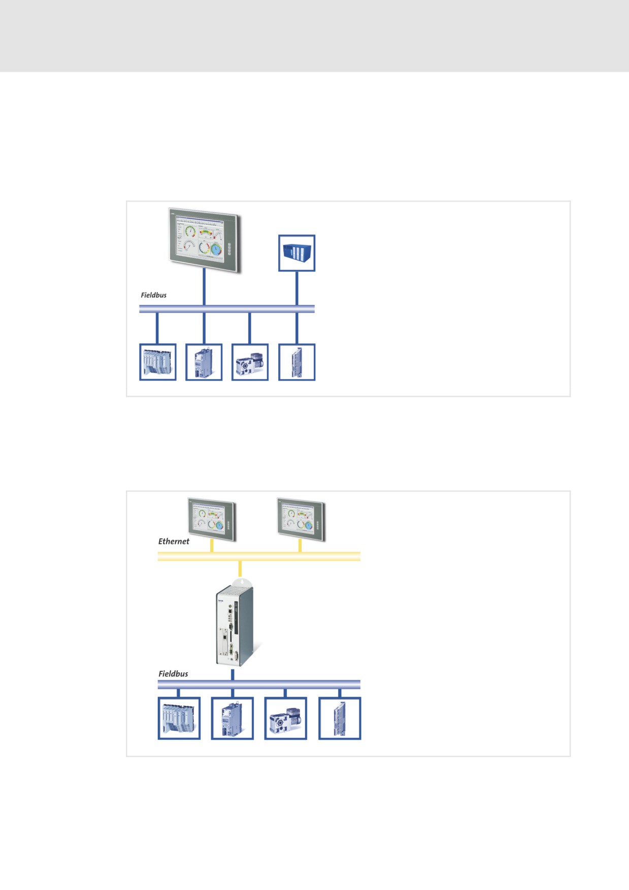
Centralised solutions:The Panel PCs of the "Embedded Line (EL)" and "Command Station
(CS)" series are compact devices and combine display, operation, and electronics in a
common housing.
Fig. 3−1
Centralised Panel PC solution
Decentralised solutions:The decentralised solutions comprise separate units: the
Industrial PC of the "Cabinet PC (CPC)" series, which is preferably placed in a protected
manner in the control cabinet, and the operating unit on site (monitor panel MP or CS−DVI).
This solution has advantages with regard to cabling, operating conditions, and
accessibility.
Fig. 3−2
Decentralised Panel PC solution
12
l
EDSIPCx7 EN 4.1
Product description
3
"Industrial PC" system
Customised solutions
Different industry sectors and ambient conditions bring about extremely differing
requirements with regard to the design of IPCs and operator panels, which due to their
complexity cannot always be implemented by means of standard components. In these
cases Lenze is the solution partner for customised developments.
Typical developments are:
ƒ Customised decoration foil for a consistent Corporate Design
ƒ Extension with components (mouse−pad, RFID, speakers, scanner,
)
ƒ Individual software adaptations
ƒ Stainless steel operator devices with minimised clearances in IP65, IP66 or IP69K.
l
13
3
Product description
Overview of designs
3.3
Overview of designs
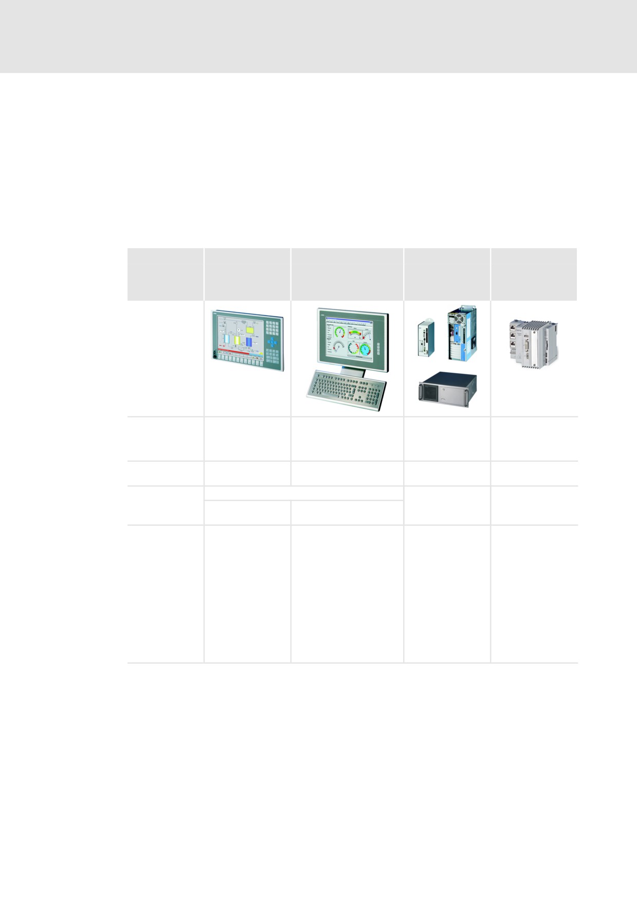
By a consequently implemented platform strategy Industrial PCs can be individually
assembled and nearly optionally scaled with regard to power, display size, and function. By
this, three different designs are provided from which the customised platform for the
automation solution can be selected in each case.
In the Embedded Line and Command Station types apart from the Industrial PCs also Thin
Clients (EL 1800 − 9800 TC, CS 5800 − 9800 TC) and monitor panels (MP 800 − 9000 DVI,
CS 5000 − 9000 DVI) are available.
Design
Embedded Line
Command Station
Cabinet PC
Cabinet PC
Type
EL 1800 − 9800
CS 5800 − 9800
CPC 2800
3241 C
EL 1800 − 9800 TC
CS 5800 − 9800 TC
CPC 5100
MP 800 − 9000 DVI
CS 5000 − 9000 DVI
CPC 9100
Mounting /
In mounting cutout
Stand−alone on a support
In the control
In the control
installation
of machine
arm or wall
cabinet on a wall
cabinet on DIN rail
panelling / control
cabinets
Enclosure
Front: IP65, rear
IP65
IP20
IP20
side: IP20
Screen
TFT display with touch sensors
Externally
Externally
26.4 cm ... 48.3 cm
38.1 cm ... 48.3 cm
(10.4" ... 19")
(15" ... 19")
Product benefits
l Compact,
l Stand−alone, robust,
l Compact,
l Compact,
mechanically
command station
mechanically
mechanically
robust panel PC
protected against dust
robust control
robust control
l Fanless
and splash water to all
cabinet PC
cabinet PC
operation is
sides
l Decentralised
l Decentralised
possible as an
l Flat design housing
design
design
option
with rear mounting
l Expansible via
l Expansible via
l Decentralised
frame
MC card
MC card
design possible
l Support arm mounting
l Expansible via
l Expansible via
or wall mounting
I/O compound
MC card
l Decentralised design
modules
possible
l Expansible via MC card
14
l
EDSIPCx7 EN 4.1
Product description
3
Overview of designs
Embedded Line
3.3.1
Embedded Line
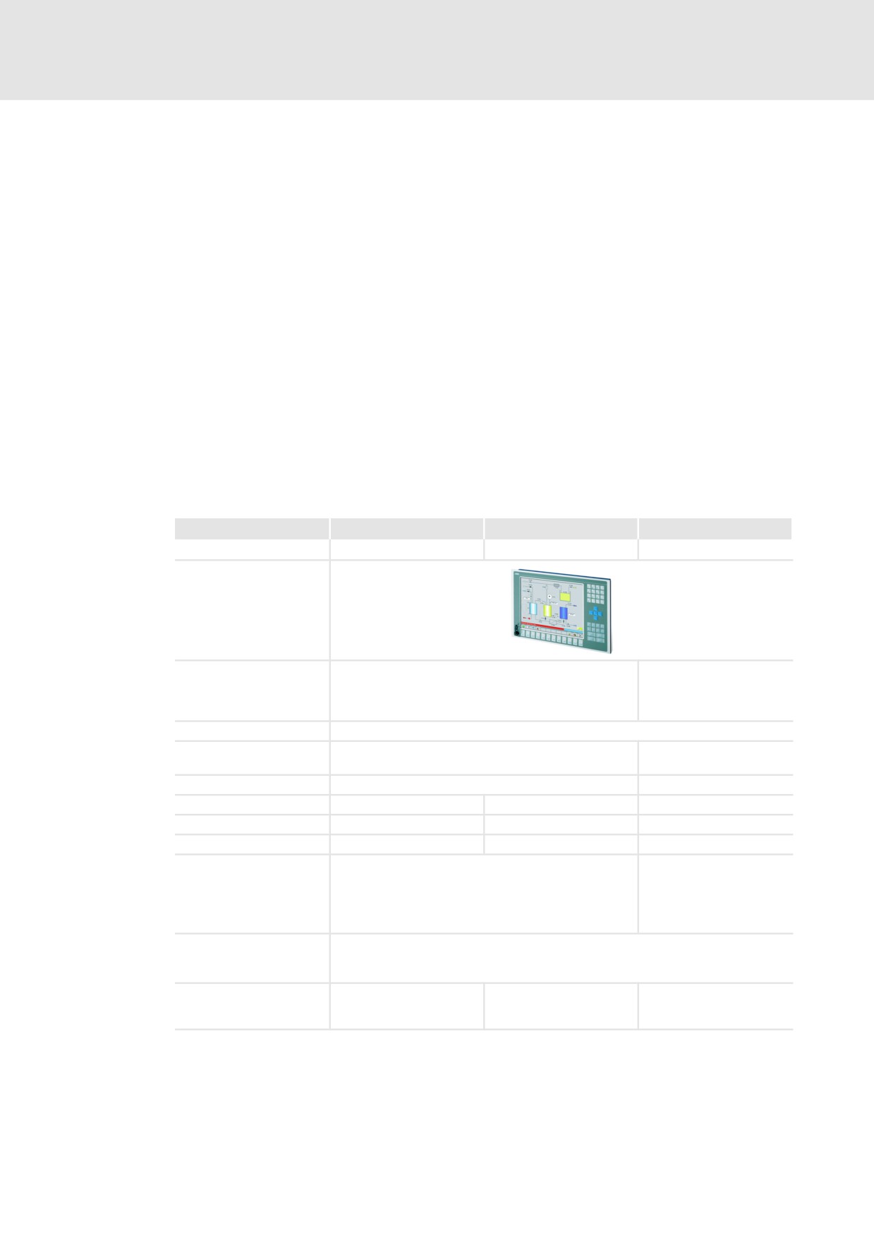
Industrial PCs of the "Embedded Line (EL)" type are panel PCs for the installation in control
cabinets, machine panelling, or other mounting cutouts. They are provided with bolts and
clamping screws on the rear side for easy mounting and a safe sealing also in rough
industrial environments.
Apart from the Industrial PCs 1800 − EL 9800, also mere displays (monitor panels and Thin
Clients) are available in this design, which can be connected as a monitor to a Cabinet PC.
Thin Clients (TC): A Thin Client terminal serves to represent and operate applications on a
remotely installed host computer via a network connection. For data transmission the
Microsoft® RDP (Remote Desktop Protocol) is used. As host computer a Windows® XP
system for an operating section or a Windows® server operating system for several
operating sections is used. All processes are carried out on the connected server, the Thin
Client only providing for the display of the graphics or of the input systems for operating
the application. The computing power of the client can therefore be kept accordingly low.
Monitor panel (MP): A monitor panel is an operator terminal to use remote Industrial PCs
as a built−in variant or stand−alone terminal. Like the Embedded Line devices, they feature
corresponding front modules.
Type
EL 1800 − 9800
EL 1800 − 9800 TC
MP 800 − 9000 DVI
Function
IPC
Thin Client
Monitor panel
20.3 cm (8"), 26.4 cm
26.4 cm (10.4"), 30.5 cm (12.1"), 38.1 cm (15") or
(10.4"), 30.5 cm (12.1"),
Screen diagonal
48.3 cm (19" inches)
38.1 cm (15") or 48.3 cm
(19" inches)
Current supply
DC24 V ±25%
Uninterruptible power
Optionally via ACU UPS control unit
−
system (UPS)
Cooling
With or without fan
Without fan
MC card slots
2
2
−
MC card
^ 29
−
−
Configurable
Yes
No
No
3 x USB type A
2 x USB type A
1 x USB type A front panel (opt.)
1 x USB type A front panel
Interfaces
1 x PS/2
(opt.)
1 x RS232
1 x USB type B
1 x LAN (10/100 Mbps)
1 x DVI
Enclosure
Front
IP65
Rear side
IP20
If Windows® CE 6.0 is
Backup
used: backup and restore
−
−
tool V2
l
15
3
Product description
Overview of designs
Command Station
3.3.2
Command Station
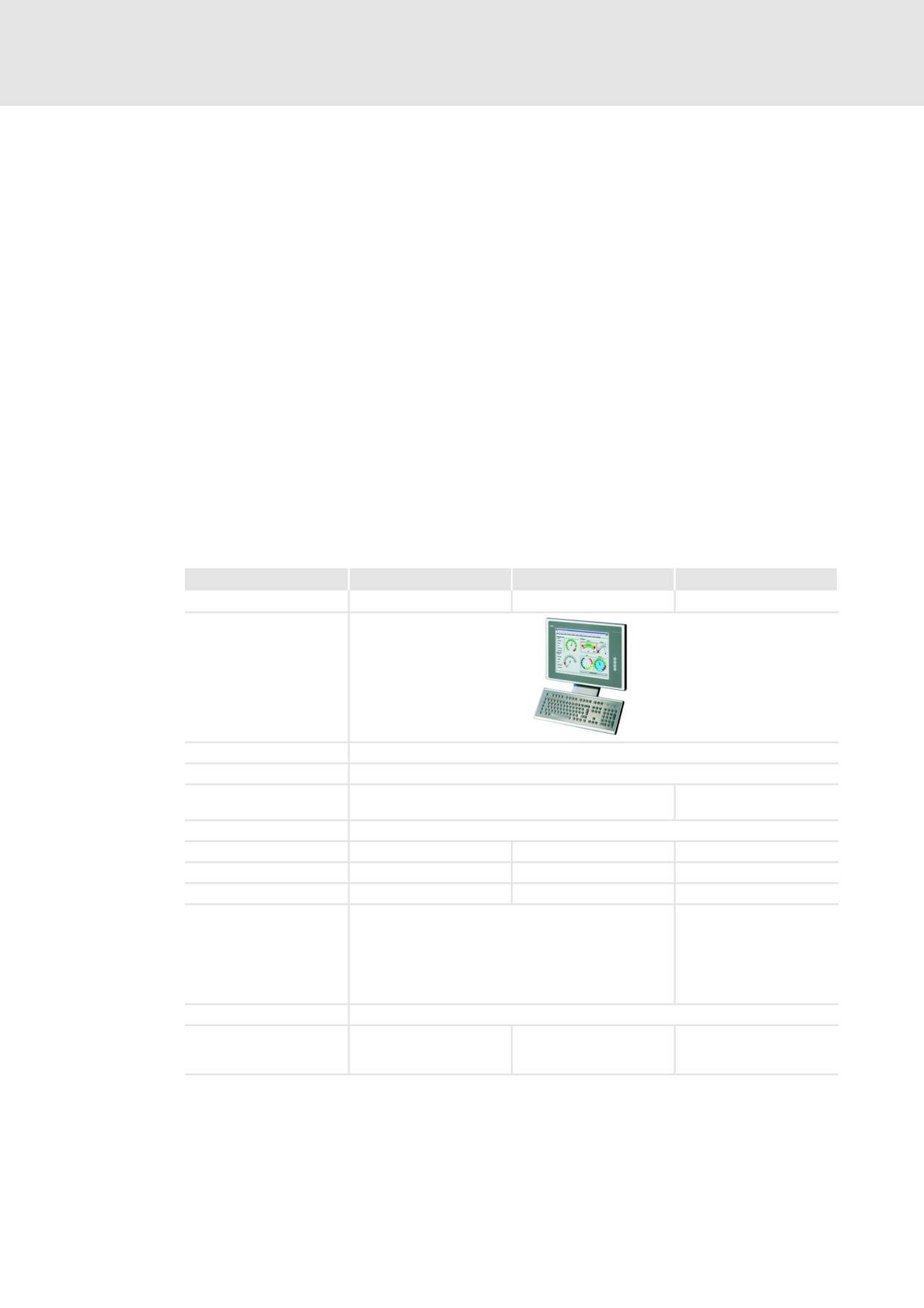
A Command Station (CS) is a stand−alone operator station which is protected against dust
and splash water at each side. The flat housing features a mounting frame on the rear side,
which can be mounted on a support arm or a wall. For the flexible implementation of
individual operating concepts the system offers numerous options and extension
consoles.
Apart from the Industrial PCs CS 5800 − 9800, also mere monitor panels and Thin Clients
are available in this design, which can be connected as a monitor to a Cabinet PC.
Thin Clients (TC): A Thin Client terminal serves to represent and operate applications on a
remotely installed host computer via a network connection. For data transmission the
Microsoft® RDP (Remote Desktop Protocol) is used. As host computer a Windows® XP
system for an operating section or a Windows® server operating system for several
operating sections is used. All processes are carried out on the connected server, the Thin
Client only providing for the display of the graphics or of the input systems for operating
the application. The computing power of the client can therefore be kept accordingly low.
Monitor panel (DVI): A monitor panel is an operator terminal to use remote Industrial PCs
as a built−in variant or stand−alone terminal. Like the command station devices, they
feature corresponding front modules and add−on components.
Type
CS 5800 − 9800
CS 5800 − 9800 TC
CS 5000 − 9000 DVI
Function
IPC
Thin Client
Monitor panel
Screen diagonal
38.1 cm (15") or 48.3 cm (19")
Current supply
DC 24 V ±25%
Uninterruptible power
Optionally via ACU UPS control unit
−
system (UPS)
Cooling
With fan
MC card slots
1
1
−
MC card
^ 29
−
−
Configurable
Yes
No
No
3 x USB type A
2 x USB type A
1 x USB type A front panel (opt.)
1 x USB type A front panel
1 x/2 x USB type A in mounting frame (opt.)
(opt.)
Interfaces
1 x PS/2
1 x USB type B
1 x RS232
1 x DVI
1 x LAN (10/100 Mbps)
1 x LAN (10/100 Mbps)
Enclosure
IP65
If Windows® CE 6.0 is
Backup
used: backup and restore
−
−
tool V2
16
l
EDSIPCx7 EN 4.1
Product description
3
Overview of designs
Cabinet PC
3.3.3
Cabinet PC
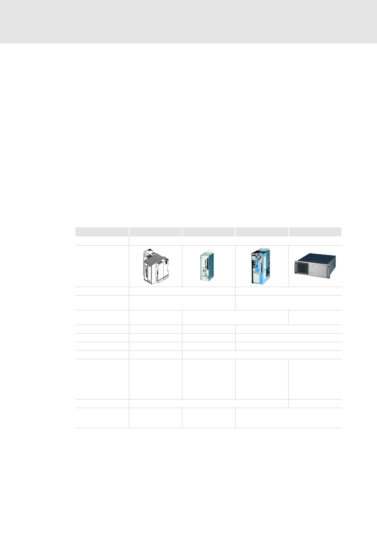
The decentralised solutions comprise separate units, the Industrial PC which is preferably
placed in a protected manner in the control cabinet, and the operating unit on site. This
solution has advantages with regard to cabling, operating conditions, and accessibility.
The following can be used as a screen:
ƒ A standard monitor.
ƒ A Monitor panel of the "Command Station" or "Embedded Line" type.
With the DVI/USB extender accessories the distance between the IPC and the monitor
panel can be up to 35 m.
ƒ A Thin Client Panel of the "Command Station" or "Embedded Line" type for
representing and operating applications which are located on a remotely installed
host computer (IPC).
The Thin Client and host computer communicate via an Ethernet connection. Like this
greater distances can be covered than with an external monitor panel. Since all
processes run on the host computer and the Thin Client solely serves to display
information and to transfer entries, the CPU performance can be selected accordingly
low.
Type
3241 C
CPC 2800
CPC 5100
CPC 9100
Function
IPC
Current supply
DC 24 V ±25%
AC 115 V ... 230 V
Uninterruptible
Optionally via ACU UPS control unit
Optionally via UPS−331
power system (UPS)
Within control
Within 19"
Mounting
Within control cabinet on a wall
cabinet on DIN rail
mounting rack
Cooling
Without fan
With or without fan
With fan
MC card slots
1
2
−
MC card
^ 29
^ 29
−
Configurable
No
Yes
3 x USB type A
8 x USB type A
10 x USB type A
3 x USB type A
1 x PS/2
2 x PS/2
2 x PS/2
1 x DVI (no VGA)
1 x RS232
1 x RS232
1 x RS232
Interfaces
2 x LAN
1 x DVI
1 x DVI
1 x DVI
(10/100 Mbps)
1 x LAN
2 x LAN
2 x LAN
1 x LAN (1 Gbps)
(10/100 Mbps)
(10/100 Mbps)
(10/100 Mbps)
Enclosure
IP20
IP20 (front IP54)
If Windows® CE is
If Windows® CE is
Backup
used: backup and
used: backup and
RAID 0, 1, 5, 10
restore tool V3
restore tool V2
l
17
3
Product description
Embedded Line (EL, MP) design
3.4
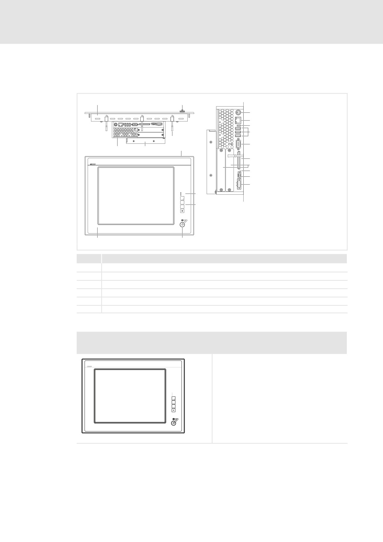
Embedded Line (EL, MP) design
Elements
PS/2
LAN
USB
RS232
CF Card
MC Card
Reset
ACU UPS
24 V DC
Power
Fail
Status
F1
F2
+
F3
-
ELx7xx−001
Pos.
Description
0
Panel PC / Thin Client / monitor panel (here EL 5800 Panel PC)
1
Front face USB port (option)
2
Screw clamp fixings
3
DVD drive (option); not for monitor panel (MP 800− 9000 DVI)
4
PC or monitor control for the monitor panel (MP 800− 9000 DVI)
5
Front face control and display elements
Overview
Panel PC EL EL 1800 / EL 1800s / EL 2800 / EL 5800 / EL 9800
Thin Client EL EL 1800 TC / EL 1800s TC / EL 2800 TC / EL 5800 TC / EL 9800 TC
Monitor Panel MP 800 DVI / MP 1000 DVI / MP 1000s DVI / MP 2000 DVI / MP 5000 DVI / MP 9000 DVI
l EL 1800 (TC): VGA touchscreen 26.4 cm (10,4")
EL 1800s (TC): SVGA touchscreen 26.4 cm (10,4")
EL 2800 (TC): SVGA touchscreen 30.5 cm (12,1")
EL 5800 (TC): XGA touchscreen 38.1 cm (15")
EL 9800 (TC): SXGA touchscreen 48.3 cm (19")
l MP 800 DVI: VGA touchscreen 20.3 cm (8")
Fail
Power
Status
MP 10000 DVI: VGA touchscreen 26.4 cm (10,4")
F1
F2+
MP 1000s0 DVI: SVGA touchscreen 26.4 cm (10,4")
F3-
MP 20000 DVI: SVGA touchscreen 30.5 cm (12,1")
MP 50000 DVI: XGA touchscreen 38.1 cm (15")
MP 90000 DVI: SXGA touchscreen 48.3 cm (19")
l 3 freely assignable function keys
CS57x0−026
18
l
EDSIPCx7 EN 4.1
Product description
3
Embedded Line (EL, MP) design
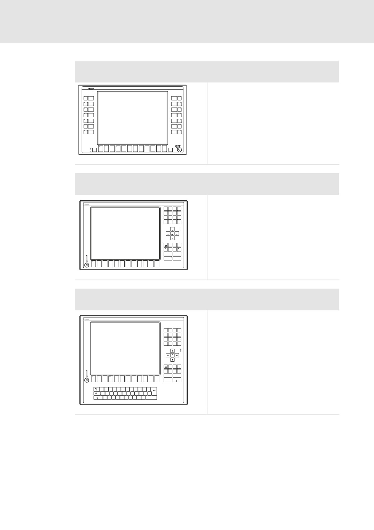
Panel PC EL 5820
Thin Client EL 5820 TC
Monitor Panel MP 5020 DVI
l XGA touchscreen 38.1 cm (15")
l 12 freely assignable function keys
S1
S8
l 14 freely assignable special keys
S2
S9
S3
S10
S4
S11
S5
S12
S6
S13
S7
S14
+
-
Power
Status
Fail
Esc
F1
F2
F3
F4
F5
F6
F7
F8
F9
F10
F11
F12
Enter
ELx7xx−002
Panel PC EL 1850 / EL 1850s / EL 2850 / EL 5850
Thin Client EL 1850 TC / EL 1850s TC / EL 2850 TC / EL 5850 TC
Monitor Panel MP 1050 DVI / MP 1050s DVI / MP 2050 DVI / MP 5050 DVI
l
EL 1850 (TC): VGA touchscreen 26.4 cm (10.4")
A
B
C
D
EL 1750s (TC): SVGA touchscreen 26.4 cm (10.4")
7
8
9
-
E
F
G
H
EL 2850 (TC): SVGA touchscreen 30.5 cm (12.1")
4
5
6
+
J
K
L
1
2
3
EL 5850 (TC): XGA touchscreen 38.1 cm (15")
M
N
O
P
0
,
/
l
MP 1050 DVI: VGA touchscreen 26.4 cm (10.4")
Pg Up
MP 1050s DVI: SVGA touchscreen 26.4 cm (10.4")
Home
End
Pg Dn
MP 2050 DVI: SVGA touchscreen 30.5 cm (12.1")
MP 5050 DVI: XGA touchscreen 38.1 cm (15")
Del
Esc
l
12 freely assignable function keys
Bs
Ctrl
Alt
Menu
Shift
Space
l
Keypad, control keys, Alpha level switch−over
Alpha
Enter
Q
+ R
- S
T
U
V
W
X
Y
Z
@
F1
F2
F3
F4
F5
F6
F7
F8
F9
F10
F11
F12
CS57x0−028
Panel PC EL 5870
Thin Client EL 5870 TC
Monitor Panel MP 5070 DVI
l
XGA touchscreen 38.1 cm (15")
l
12 freely assignable function keys
l
MF2 keyboard
7
8
9
-
$
&
4
5
6
+
"
§
1
2
3
=
>
0
,
<
|
/
Bs
Einfg
Entf
Bild
Alt Gr
Pos 1
Ende
Bild
+
-
Alt
Strg
F1
F2
F3
F4
F5
F6
F7
F8
F9
F10
F11
F12
Esc
Q
@
W
E
€
R
T
Z
U
I
O
P
Ü
+
~
A
S
D
F
G
H
J
K
L
Ö
Ä
?
Enter
ß
\
Y
X
C
V
B
N
M
;
:
_
Space
μ
,
-
CS57x0−029
l
19
3
Product description
Command Station (CS) design
3.5
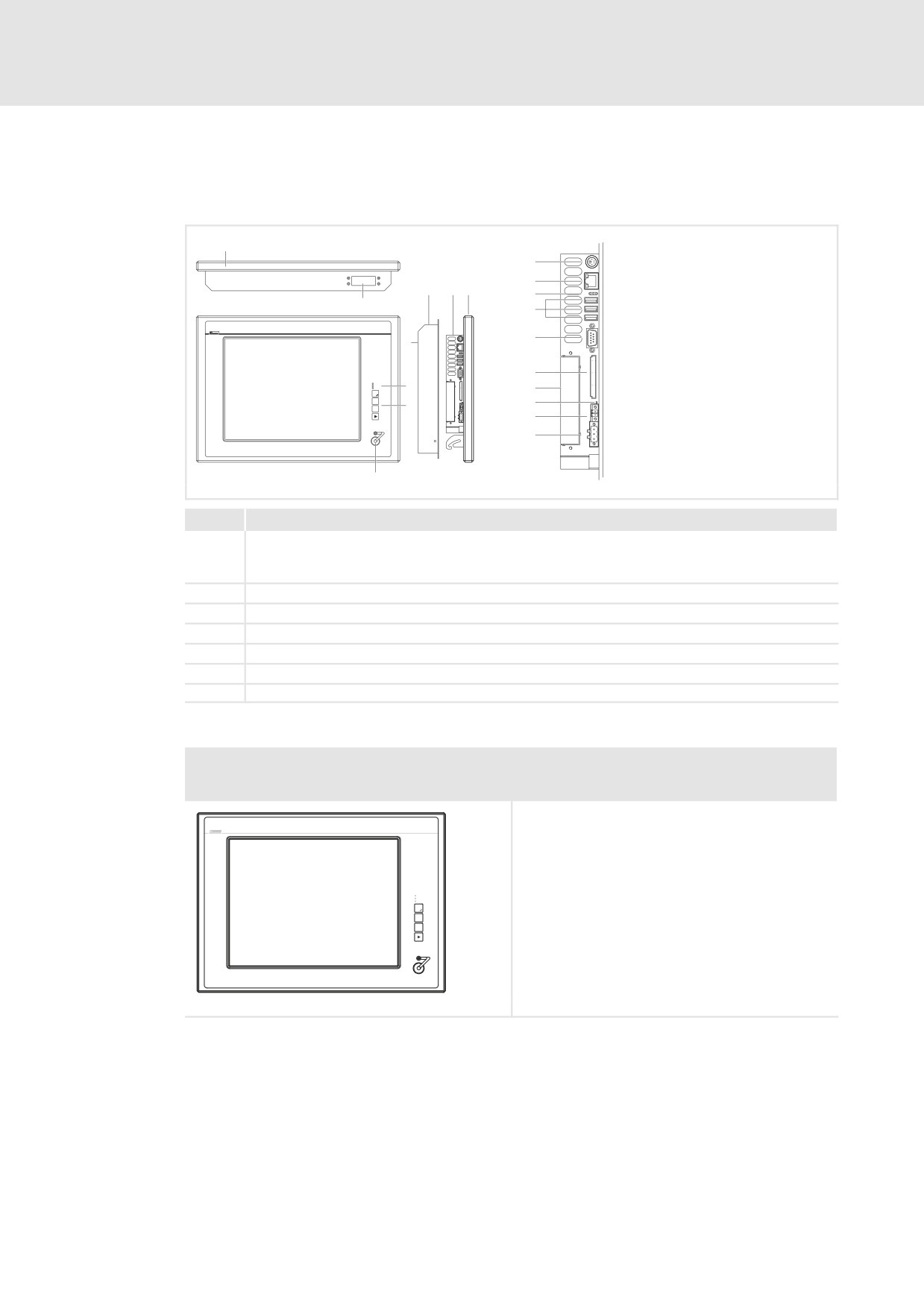
Command Station (CS) design
Elements
PS/2
LAN
USB
RS232
CF Card
F1
MC Card
F2
+
F3
-
Reset
ACU UPS
24 V DC
CS57x0−001
Pos.
Description
0
Command Station (IPC, here CS 5800)
Command Station TC (Thin Client)
Command Station DVI (monitor panel)
1
Mounting frame with VESA−100 adapter surface
2
PC or monitor control for the monitor panel
3
Screen
4
Front face control and display elements
5
Front face USB port (option)
6
Mounting frame connecting plate (option)
Overview
Command Station CS 5800 / CS 9800
Command Station CS 5800 TC / CS 9800 TC
Command Station CS 5000 DVI / CS 9000 DVI
l CS 5800 (TC): XGA touchscreen 38.1 cm (15")
CS 9800 (TC): SXGA touchscreen 48.3 cm (19")
l CS 5000 DVI: XGA touchscreen 38.1 cm (15")
CS 9000 DVI: SXGA touchscreen 48.3 cm (19")
l 3 freely assignable function keys
Power
Fail
Status
F1
F2
+
F3
-
CS57x0−026
20
l
EDSIPCx7 EN 4.1
Product description
3
Command Station (CS) design
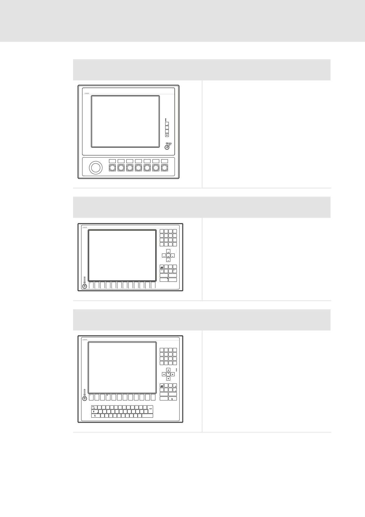
Command Station CS 5810
Command Station CS 5810 TC
Command Station CS 5010 DVI
l XGA touchscreen 38.1 cm (15")
l 3 freely assignable function keys
l Up to 7 freely assignable switching elements
(^ LEERER MERKER)
l Emergency−off switch
Power
Fail
Status
F1
F2
+
F3
-
CS57x0−027
Command Station CS 5850
Command Station CS 5850 TC
Command Station CS 5050 DVI
l
XGA touchscreen 38.1 cm (15")
A
B
C
D
l
12 freely assignable function keys
7
8
9
-
E
F
G
H
4
5
6
+
l
Keypad, control keys, Alpha level switch−over
J
K
L
1
2
3
M
N
O
P
0
,
/
Pg Up
Home
End
Pg Dn
Del
Esc
Bs
Ctrl
Alt
Menu
Shift
Space
Alpha
Enter
Q
+ R
- S
T
U
V
W
X
Y
Z
@
F1
F2
F3
F4
F5
F6
F7
F8
F9
F10
F11
F12
CS57x0−028
Command Station CS 5870
Command Station CS 5870 TC
Command Station CS 5070 DVI
l
XGA touchscreen 38.1 cm (15")
l
12 freely assignable function keys
l
MF2 keyboard
7
8
9
-
$
&
4
5
6
+
"
§
1
2
3
=
>
0
,
<
|
/
Bs
Einfg
Entf
Bild
Alt Gr
Pos 1
Ende
Bild
+
-
Alt
Strg
F1
F2
F3
F4
F5
F6
F7
F8
F9
F10
F11
F12
Esc
Q
@
W
E
€
R
T
Z
U
I
O
P
Ü
+
~
A
S
D
F
G
H
J
K
L
Ö
Ä
?
Enter
ß
\
Y
X
C
V
B
N
M
;
:
_
Space
μ
,
-
CS57x0−029
l
21
3
Product description
Command Station (CS) design
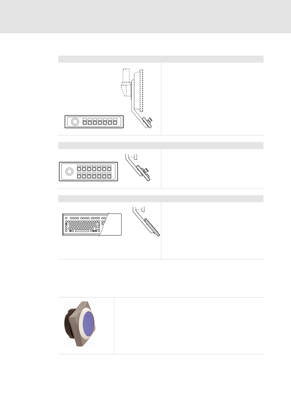
Add−on components (accessories)
Operator console CSB 7
l Up to 7 freely assignable switching elements that
can be used in any combination
l Emergency−off switch
l Internal cabling for Command Station with
Combicon plug
CS57x0−030
Operator console CSB 14
l Up to 14 freely assignable switching elements that
can be used in any combination
l Emergency−off switch
l Internal cabling for Command Station with
Combicon plug
CS57x0−031
Keyboard CSB MF2 E
l MF2 keyboard with long−throw keys in stainless
steel finish
l Internal cabling for Command Station with USB
Esc
c
F
F
F
F4
F5
F6
F7
F8
F9
F
100
F
F12
Druckuck
Rollen
°^
1
§
4 $
5
6
&
7 {
8
9
=0 }
ß?
`
Einfg
Pos.
plug
Q@
W
E€
R
T
Z
U
I
O
P
Ü
+
*~
Entf
A
S
D
F
G H
J
K
L
Ö
Ä
#
l Design types:
<
>
|
Y X C
V
B
N
M
;
:
_
Strg
Alt
AltGr
Strg
– with NUM block
- with touch pad
l Available languages:
- German, English, French
- Others on request
CS57x0−033
Add−on components with combinations of operator console and keyboard are available.
The operator consoles can be assembled with RAFI control/display elements of the RAFIX
22 FS type (printed circuit board mounting). The design is adapted to the visual appearance
of the Command Station.
Control/Display elements of type RAFIX 22 FS
l Square−law flange, dark grey
l Flat front ring, silver metallic
l Lighting by very bright LED
l Colour of fascia panel white, yellow, green, red, or blue
l Key−operated switch with two keys; different versions available
l Emergengy stop pushbutton
- With potential−free contacts
- With unlabelled yellow sticker (Æ60 mm, in accordance with DIN EN ISO
13850)
CSB−002
22
l
EDSIPCx7 EN 4.1
Product description
3
Cabinet PC (CPC) design
3241 C
3.6
Cabinet PC (CPC) design
3.6.1
3241 C
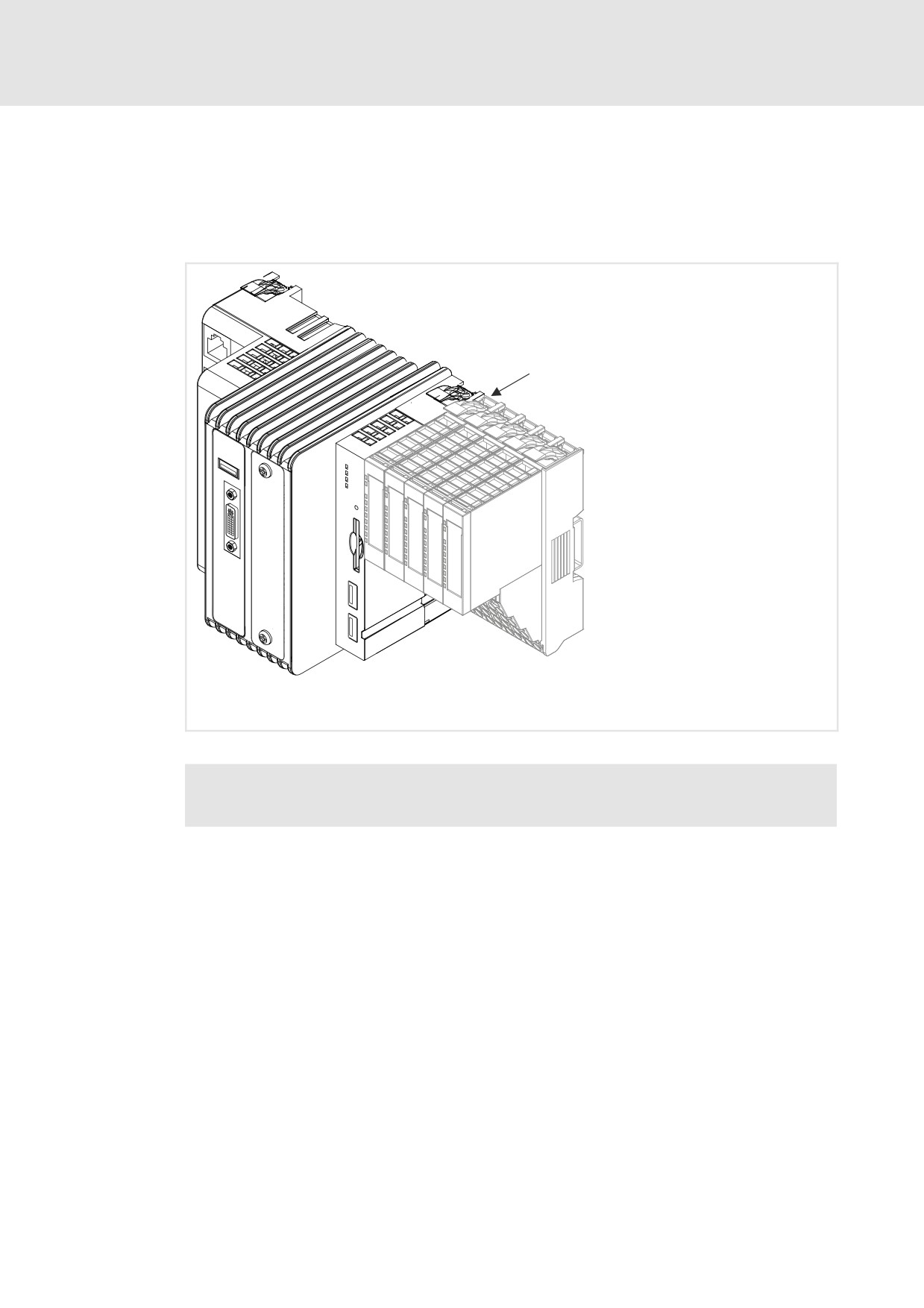
System overview
EPM-S701
IPC 3241 C
I/O System 1000
32xxC_005
Fig. 3−3
IPC 3241 C with connected I/O system 1000 (grey)
,
For information on the I/O system 1000, please refer to the system manual
"I/O system 1000".
l
23
3
Product description
Cabinet PC (CPC) design
3241 C
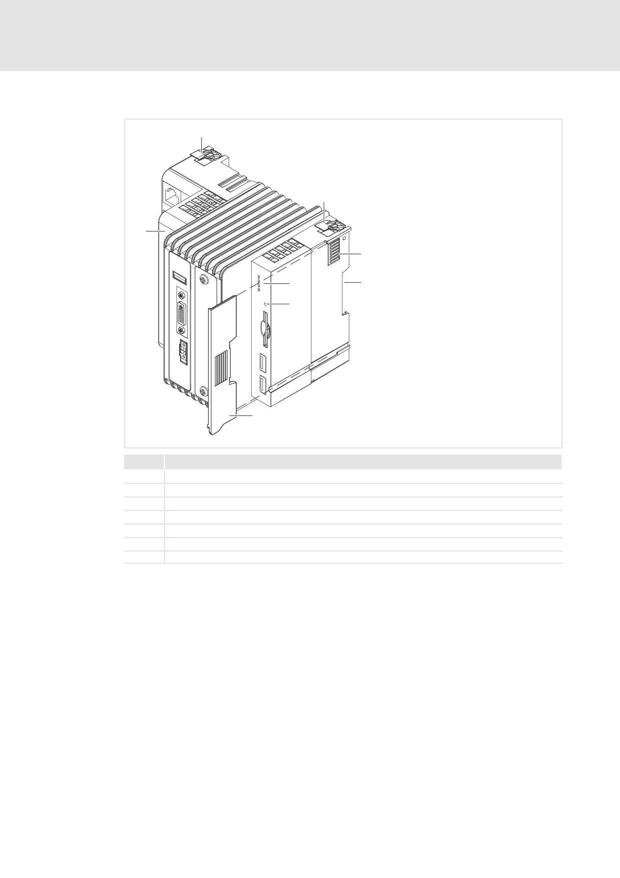
Elements
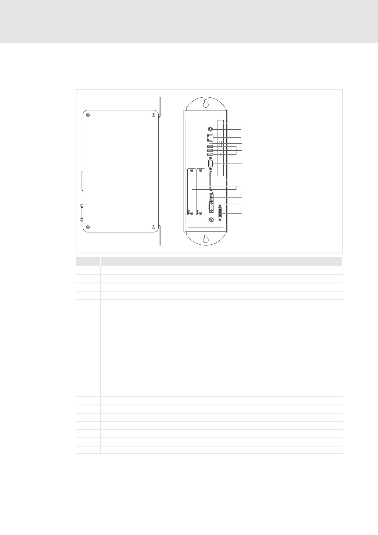
32xxC−001
Pos.
Description
0
IPC 3241 C
1
Locking lever (DIN rail)
2
Backplane bus contacts
3
Guide for DIN rail with thermal connection via GapPad strips
4
Status LEDs
5
Reset button
6
Contact cover
24
l
EDSIPCx7 EN 4.1
Product description
3
Cabinet PC (CPC) design
CPC 2800
3.6.2
CPC 2800
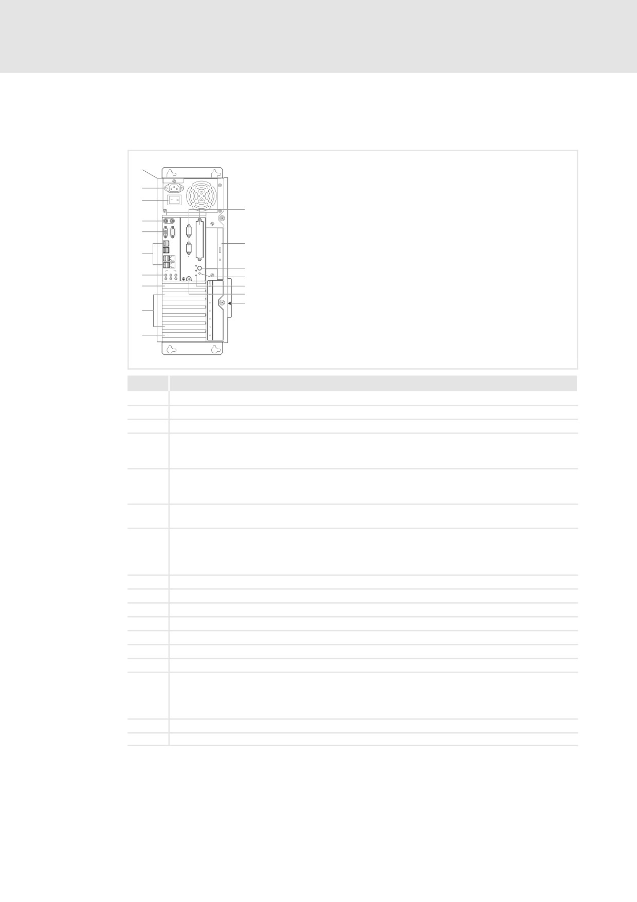
Elements
CPC2700−001
Pos.
Description
0
Control cabinet PC
1
DVD drive (optional)
2
PS/2
3
LAN (Ethernet)
4
Status LEDs
Error (red):
l Is lit if a power supply failure has occurred;
HD (yellow):
l Indicates access to a storage medium.
Power (green):
l Is lit when the supply voltage is present.
l Flashes (−−−−−−−−) in the case of a hardware error.
l Is blinking (−−−−−−) when the ACU UPS (optional) is being charged.
l Is blinking (−−−−−−−−) when there is a supply voltage failure and the device is being supplied by the ACU
UPS.
l Is blinking (−−−−) when the supply voltage of the ACU UPS is too low (e.g. rechargeable battery is
empty or missing).
l Blinks 4 x per second if the ACCU−PACK causes a short circuit or if the CAPS−PACK is completely
discharged.
5
USB
6
RS 232
7
CF Card
8
MC Card
9
ACU UPS
:
24 V DC
;
DVI
l
25
3
Product description
Cabinet PC (CPC) design
CPC 5100
3.6.3
CPC 5100
Elements
KEYB MOUSE
VGA
COM1
X1
USB
X2
POWER
STANDBY
USB
AUDIO
LAN
HD
MIC OUT
IN
CTRL RESET
CPC5100−001
Pos.
Description
0
Control cabinet PC
1
Mains connection 115 ... 230 V AC
2
Mains switch
3
From left to right:
l Keyboard connection (PS/2)
l Mouse connection (PS/2)
4
From left to right:
l Analog monitor connection (VGA)
l Serial interface (COM1)
5
8 x USB−A
2 x Ethernet (RJ45)
6
From left to right:
l Microphone
l Audio line−out
l Audio line−in
7
Digital monitor connection (DVI on PCIe expansion card)
8
5 x PCI slot
9
PCIe x4 slot (in x16 socket)
:
Optionally assigned interfaces
;
DVD drive (option)
<
Stand−by pushbutton
=
Reset pushbutton
>
From the top to the bottom:
l Power LED (is lit if mains voltage is applied)
l HD−LED (is lit if the hard disk is accessed)
l CTRL−LED (green: housing fan in operation; red: housing fan out of service)
?
PE terminal screw (protective conductor)
@
Labelling field for the terminal and slot assignment
26
l
EDSIPCx7 EN 4.1
Product description
3
Cabinet PC (CPC) design
CPC 9100
3.6.4
CPC 9100
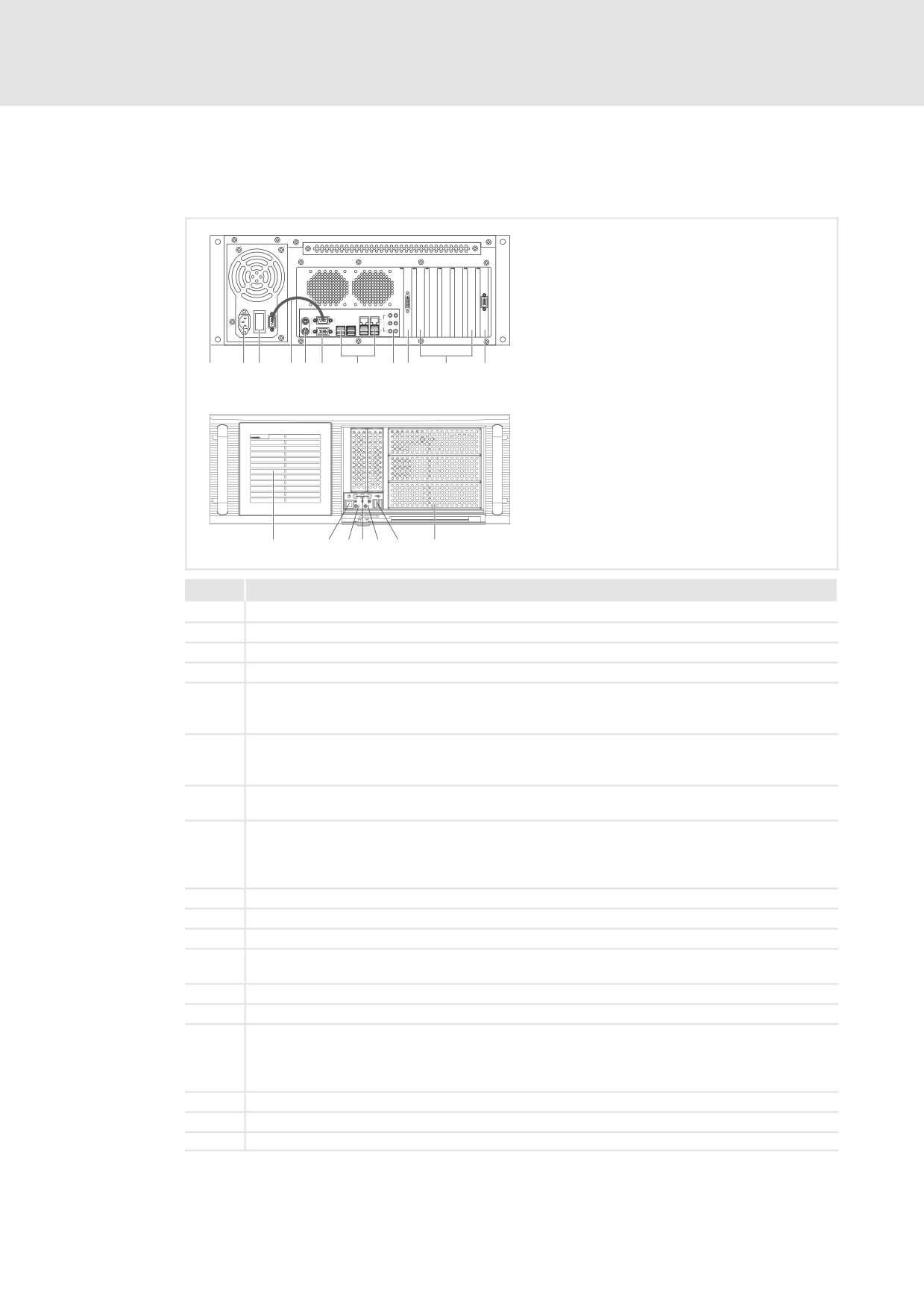
Elements
CPC9100−001
Pos.
Description
0
Control cabinet PC
1
Mains connection 115 ... 230 V AC
2
Mains switch
3
UPS control cable (only for power supply unit with integrated UPS)
4
from bottom to top:
l Keyboard connection (PS/2)
l Mouse connection (PS/2)
5
from bottom to top:
l Analog monitor connection (VGA)
l Serial interface (COM1)
6
8 x USB−A
2 x Ethernet (RJ45)
7
from bottom to top:
l Microphone
l Audio line−out
l Audio line−in
8
Digital monitor connection (DVI to PCIe expansion card)
9
5 x PCI slot
:
1 x optional PCIe x4 slot (in x16 socket)
;
3 x optionally assigned 5.25" bays (e.g. for DVD drives, hard disks in removable rack, battery packs for
UPS)
<
2 x USB−A
=
No function
>
from left to right:
l Power LED (is illuminated when mains voltage is applied)
l HD−LED (is illuminated when hard disk is accessed)
l Fan−LED (no function)
?
Reset pushbutton
@
Power pushbutton
Device fan (hot−swappable)
l
27
3
Product description
Options
Overview
3.7
Options
3.7.1
Overview
Option
For the use with
Function
ACU UPS control unit
l CS 5800 ... CS 9800
For expansion of the IPC by
l EL 1800 ... EL 9800
UPS functionality
l CPC 2800
l 3241 C
3.7.2
ACU UPS control unit
Description
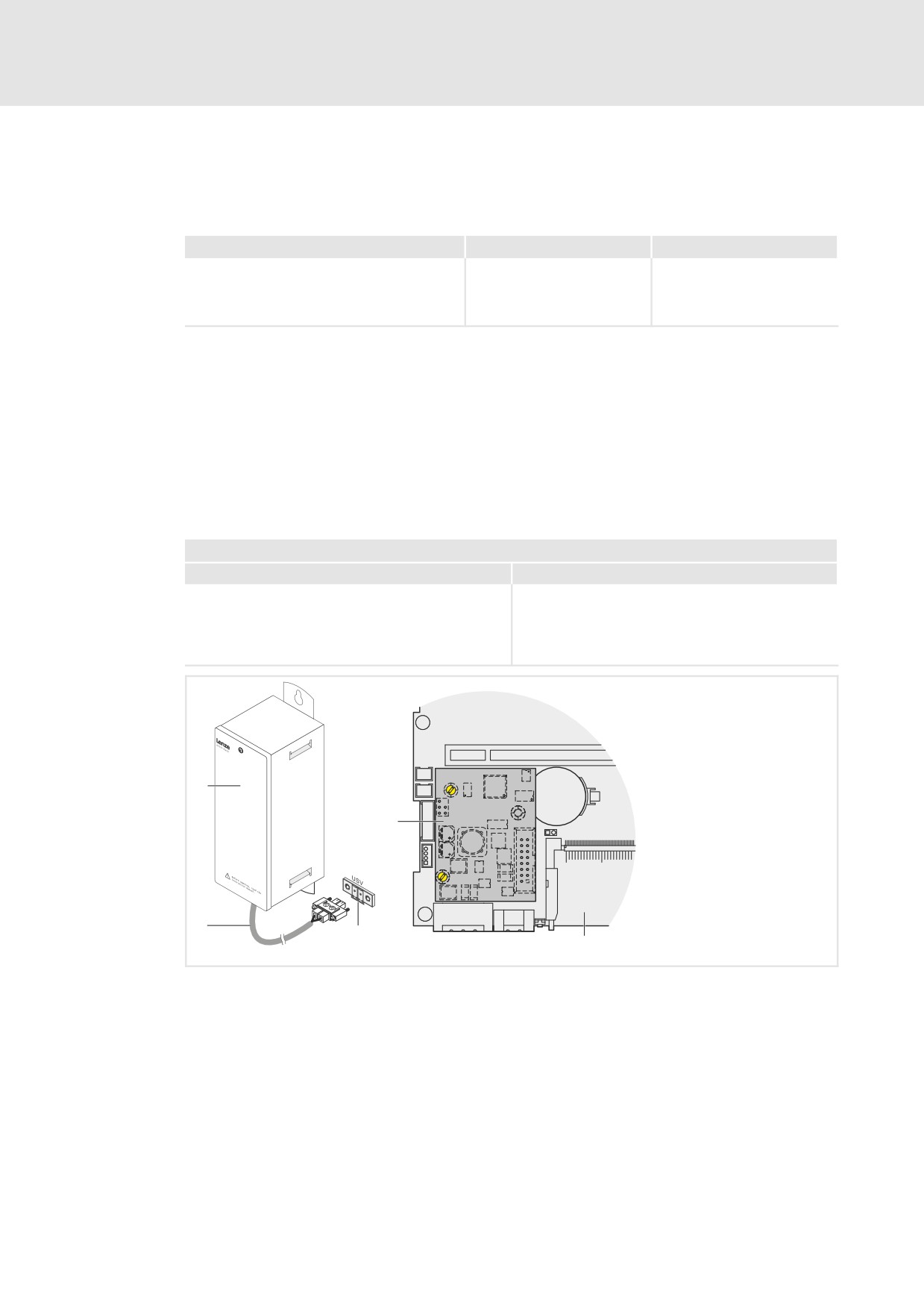
The optional ACU UPS control unit in connection with a battery or capacitor pack adds a
UPS functionality to the Industrial PC of the EL 1800−9800, CS 5800−9800, CPC 2800, and
3241 C series.
The ACU UPS control unit is either pre−equipped by the factory or can be refitted by the
Lenze Service staff.
Features of the ACU UPS control unit
with battery pack (ACCU PACK)
with capacitor pack (CAPS PACK)
l Bridges a short−term mains failure or mains
l Data backup in the event of mains failure.
fluctuations and shuts down the PC.
l Not suitable for Windows XP and Windows
l Software−based configuration
Embedded Standard 2009.
l ^ Documentation for the battery pack
l Software−based configuration
l ^ Documentation for the capacitor pack
EPC50
FAN3
FAN2
CR2450
F1
T4A
ACCU
RESET
POWER
CS57x0−042
0
2700 battery pack or 2701 capacitor pack (accessories)
1
Connection cable (included in delivery of battery pack/capacitor pack)
2
Port on industrial PC
3
ACU UPS control unit
4
Baseboard
28
l
EDSIPCx7 EN 4.1
Product description
3
Accessories
Overview
3.8
Accessories
3.8.1
Overview
Accessories
Function
For the use with
MC−CAN2
For connection to a CAN fieldbus;
l
IPC 3241 C
the card features 2 independent
l
IPC CPC 2800
CAN interfaces
l
IPC CS 5800 − 9800
l
IPC EL 1800 − 9800
MC−ETC
For connection to a EtherCAT
l
IPC 3241 C
network
l
IPC CPC 2800
l
IPC CS 5800 − 9800
l
IPC EL 1800 − 9800
MC−ETH
For connection to a Ethernet
l
IPC 3241 C
network
l
IPC CPC 2800
l
IPC CS 5800 − 9800
l
IPC EL 1800 − 9800
MC−ISI
For the connection to RS 232,
l
IPC 3241 C
RS 422, or RS 485; the card has 2
l
IPC CPC 2800
independent serial interfaces
l
IPC CS 5800 − 9800
l
IPC EL 1800 − 9800
MC−PBM
For connection to a PROFIBUS
l
IPC 3241 C
system as master
l
IPC CPC 2800
l
IPC CS 5800 − 9800
l
IPC EL 1800 − 9800
MC−PBS
For connection to a PROFIBUS
l
IPC 3241 C
system as slave
l
IPC CPC 2800
l
IPC CS 5800 − 9800
l
IPC EL 1800 − 9800
MC−PNC
For connection to a PROFINET
l
IPC 3241 C
system as control system (controller
l
IPC CPC 2800
interface connection)
l
IPC CS 5800 − 9800
l
IPC EL 1800 − 9800
MC−PND
For connection to a PROFINET
l
IPC 3241 C
system as device (device interface
l
IPC CPC 2800
connection)
l
IPC CS 5800 − 9800
l
IPC EL 1800 − 9800
DVI/USB extender
For the decentralised configuration
l
Monitor panel MP 800 − 9000 DVI
between the computer unit and the
l
Monitor panel CS 5000 − 9000 DVI
operating/display unit
l
IPC 3241 C
l
IPC CPC 2800
l
IPC CPC 5100
l
IPC CPC 9100
,
For further information please see the corresponding separate manuals.
l
29
3
Product description
Software
Operating system (accessories)
3.9
Software
3.9.1
Operating system (accessories)
Industrial PC
Operating
Description
Storage medium
system
EL 1800 − 9800
Windows XPââ
l Professional with SP3
l Hard disk 1)
CS 5800 − 9800
Multilanguage
l Pre−installed languages: English, German,
CPC 2800, CPC 5100,
French, Spanish, Portuguese (Brazil),
CPC 9100
Chinese (P.R. of China)
EL 1800 − 9800
Windowsâ
l Component version of Windows XPâ
l Hard disk
CS 5800 − 9800
Embedded
Professional, where the necessary
l Compact Flash
3241 C
Standard 2009
software components and drivers are
card
factory−set.
l Only 3241 C: on
l Pre−installed languages: English, German
flash memory of
l For the different processor types adapted
the device
image files are available.
EL 1800 − 9800
Windows CEâ 6
l Real−time capable operating system with
l Compact Flash
CS 5800 − 9800
Prof.
low resource requirements
card
CPC 2800
l For the different processor types adapted
installations are available (not for Coreä
Duo).
1)
The Industrial PC must be equipped with a hard disk.
,
For further information please see the corresponding separate manuals.
3.9.2
Other software types
Industrial PC
Software
Description
EL 1800 − 9800 TC
Thin Client connection
l Terminal Client Manager for configuring the
CS 5800 − 9800 TC
manager
connection to the server and the desired programs.
3241 C
Backup and restore
l These tools provide the possibility of copying the flash
tool V3
memory to a USB stick. A restore can be carried out by
inserting the USB stick and switching on the voltage, or
by means of a tool. An option to manage the archives
Devices with Windows CEâ
Backup and restore
can be configured.
6.0:
tool V2
l By carrying out a restore as described above, the
EL 1800 − 9800
replacement device can be set to a state identical to
CS 5800 − 9800
the one the original device had during the backup.
CPC 2800
l For further information please refer to the backup and
restore tool manual
,
For further information please see the corresponding separate manuals.
30
l
EDSIPCx7 EN 4.1
Product description
3
Fan monitoring with "Smart Cool" and "FAN Service" (option)
3.9.3
Fan monitoring with "Smart Cool" and "FAN Service" (option)
The "Smart Cool" and "Fan service" softwares can be used for the following IPCs:
ƒ EL 1800 − 9800
ƒ CS 5800 − 9800
ƒ CPC 2800
"Smart Cool"
Forced−ventilated industrial PCs are always provided with a temperature monitoring
system which is controlled via the "Smart Cool" software.
A thermal sensor measures the temperature inside the housing of the industrial PC. When
a preset temperature is exceeded, the fans of the industrial PC are switched on by "Smart
Cool". When the temperature has dropped again, "Smart Cool" switches off the fans.
A default setting depending on the installed PC components determines which fans in the
industrial PC are to be controlled by the software and at which temperature the fans are
to be switched on.
The software starts automatically together with the operating system and runs in the
background.
You can open the user interface of "Smart Cool" via the identically−named entry in the
system control. The user interface provides option boxes for selecting one of the following
states:
"Smart Cool" state: Temperature monitoring is active and operates as described above
(default setting).
"FAN on" state: All fans of the industrial PC are running continuously.
The assigned state remains selected even after a restart.
"FAN service"
The "FAN service" is installed together with "Smart Cool". It monitors the fans of the
Industrial PC and reports (Windows window) or logs (log file) the following system states:
ƒ Fan failure
ƒ Defective or empty buffer battery
The "FAN service" runs in the background and has no user interface.
Location of the "LogFanService.txt" log file:
ƒ Windows Embedded Standard 2009 and Windows XP Multilanguage in the "Smart
Cool" program folder
(e.g. "x:\Programs\Lenze\SmartCool\)
ƒ For Windows CE in the folder "x:\Storage\DeviceScanner\"
) Note!
In order to prevent the log file size from getting too large, its data are
transferred to the "LogFanService.bak" file as soon as the file size exceeds
100 kB.
l
31
Q
F Lenze Automation GmbH
Service
Lenze Service GmbH
Hans−Lenze−Str. 1
Breslauer Straße 3
D−31855 Aerzen
D−32699 Extertal
Germany
Germany
(
+49 (0)51 54 / 82−0
(
00 80 00 / 24 4 68 77 (24 h helpline)
Ê
+49 (0)51 54 / 82 − 28 00
Ê
+49 (0)51 54 / 82−11 12
Lenze@Lenze.de
Service@Lenze.de
EDSIPCx7 § .N+_ § EN § 4.1 § TD29
10
9
8
7
6
5
4
3
2
1