Beckhoff C6915 Industrial PC. Manual (Version: 2.5)
Table of contents
Table of contents
1
Notes on the documentation
5
2
For your safety
6
2.1
Description of safety symbols
6
2.2
Intended use
6
2.3
Fundamental safety instructions
7
2.4
Operator's obligation to exercise diligence
7
2.5
Notes on information security
8
3
Product overview
9
3.1
Structure
10
3.2
Interface description
11
3.2.1
Power supply
11
3.2.2
Ethernet RJ45
12
3.2.3
USB
13
3.2.4
DVI
14
3.3
Status LEDs
15
3.4
Name plate
16
4
Commissioning
17
4.1
Transport and unpacking
17
4.2
Installation in the control cabinet
18
4.2.1
Dimensions
19
4.2.2
Installation in the control cabinet
20
4.3
Connecting the Industrial PC
21
4.3.1
Installing the supply cable
22
4.3.2
Grounding of the Industrial PC
23
4.3.3
Connecting cables and power supply
24
4.4
Switching the Industrial PC on and off
26
5
Beckhoff Device Manager
28
6
Decommissioning
30
6.1
Disconnecting the power supply and cables
30
6.2
Disassembly and disposal
31
7
Maintenance
32
7.1
Cleaning
32
7.2
Maintenance
33
7.2.1
Access to device components
35
7.2.2
Replacing the battery
36
7.2.3
Replacing the storage media
37
8
Troubleshooting
38
9
Technical data
39
10 Appendix
40
10.1
Service and support
40
10.2
Approvals
41
Version: 2.5
3
Table of contents
4
Version: 2.5
Notes on the documentation
1
Notes on the documentation
This description is only intended for the use of trained specialists in control and automation engineering who
are familiar with the applicable national standards.
The following instructions and explanations must be followed during installation and commissioning of the
components. The responsible staff must ensure that the application or use of the products described satisfy
all the requirements for safety, including all the relevant laws, regulations, guidelines and standards.
Disclaimer
The documentation has been prepared with care. The products described are, however, constantly under
development. For that reason the documentation is not in every case checked for consistency with
performance data, standards or other characteristics. In the event that it contains technical or editorial errors,
we retain the right to make alterations at any time and without warning. No claims for the modification of
products that have already been supplied may be made on the basis of the data, diagrams, and descriptions
in this documentation. All illustrations shown are only examples. The configurations depicted may deviate
from the standard.
Trademarks
Beckhoff®, TwinCAT®, TwinCAT/BSD®, TC/BSD ®, EtherCAT®, EtherCAT G®, EtherCAT G10®, EtherCAT P®,
Safety over EtherCAT®, TwinSAFE®, XFC®, XTS® and XPlanar® are registered and licensed trademarks of
Beckhoff Automation GmbH.
Other designations used in this publication may be trademarks whose use by third parties for their own
purposes could violate the rights of the owners.
Patents
The EtherCAT Technology is covered, including but not limited to the following patent applications and
patents: EP1590927, EP1789857, EP1456722, EP2137893, DE102015105702 and similar applications and
registrations in several other countries.
Copyright
prohibited. Offenders will be held liable for the payment of damages. All rights reserved in the event of the
grant of a patent, utility model or design.
Delivery state
All the components are supplied in particular hardware and software configurations appropriate for the
application. Changes to the hardware or software configuration are permitted, provided they are within the
specified limits for power consumption and power loss (please refer to the respective data sheet).
Delivery conditions
In addition, the general delivery conditions of the company Beckhoff Automation GmbH & Co. KG apply.
Version: 2.5
5
For your safety
2
For your safety
The Safety chapter first explains the safety symbols used in the documentation and their meanings. They
contain fundamental safety instructions that are essential for the avoidance of personal injuries and damage
to property.
Exclusion of liability
Beckhoff shall not be liable in the event of non-compliance with this documentation and thus the use of the
devices outside the documented operating conditions.
2.1
Description of safety symbols
The following safety symbols are used in these operating instructions. In order to avoid personal injuries and
damage to property, read and follow the safety and warning notices.
Warning of personal injuries:
DANGER
Disregarding the safety notice will lead to death or serious injuries.
WARNING
Disregarding the safety notice may lead to death or serious injuries.
CAUTION
Disregarding the safety notice may lead to minor injuries.
Warning of damage to property:
NOTE
Disregarding the notice may lead to damage to property.
2.2
Intended use
The Industrial PC is intended for control cabinet installation and use as a control system in machine
construction and plant engineering for automation, visualization and communication.
The Industrial PC has been developed for an IP20 working environment. It is protected against the
penetration of fingers and solid foreign bodies of 12.5 mm or larger in size. It is not protected against water.
Operation of the devices in wet and dusty environments is not permitted.
The specified limits for technical data must be adhered to.
The Industrial PC can be used within the documented operating conditions.
Improper use
Do not use the Industrial PC outside the documented operating conditions.
6
Version: 2.5
For your safety
2.3
Fundamental safety instructions
The following safety instructions must be observed when handling the Industrial PC.
Application conditions
• Do not use the Industrial PC under extreme environmental conditions.
• Never use the Industrial PC in potentially explosive atmospheres.
• Do not carry out any work on the Industrial PC when it is live. Always switch off the supply voltage for
the device before mounting it, replacing device components or rectifying malfunctions. This does not
apply to the replacement of hard disks in a RAID configuration.
• Never plug or unplug connectors during thunderstorms. There is a risk of electric shock.
• Ensure that the device has a protective and functional earth connection.
Damage to property, loss of data and impairment of functions
• If you change the hardware and software configurations, you must keep within the specified limits of
power consumption and power dissipation (please refer to the respective data sheet).
• Ensure that only trained specialists with a control and automation technology background, operate the
Industrial PC. Use by unauthorized persons can lead to damage to property and loss of data.
• Protect the power supply cable with a fuse with a max. rating of 16 A. The fuse serves to protect the
supply line in the event of a short circuit.
• In case of fire, extinguish the Industrial PC with powder or nitrogen.
2.4
Operator's obligation to exercise diligence
The operator must ensure that
• the products are used only for their intended purpose (see Chapter 2.2 Intended use [} 6]).
• the products are only operated in sound condition and in working order.
• the products are operated only by suitably qualified and authorized personnel.
• the personnel is instructed regularly about relevant occupational safety and environmental protection
aspects, and is familiar with the operating instructions and in particular the safety instructions contained
herein.
• the operating instructions are in good condition and complete, and always available for reference at the
location where the products are used.
Version: 2.5
7
For your safety
2.5
Notes on information security
The products of Beckhoff Automation GmbH & Co. KG (Beckhoff), insofar as they can be accessed online,
are equipped with security functions that support the secure operation of plants, systems, machines and
networks. Despite the security functions, the creation, implementation and constant updating of a holistic
security concept for the operation are necessary to protect the respective plant, system, machine and
networks against cyber threats. The products sold by Beckhoff are only part of the overall security concept.
The customer is responsible for preventing unauthorized access by third parties to its equipment, systems,
machines and networks. The latter should be connected to the corporate network or the Internet only if
appropriate protective measures have been set up.
In addition, the recommendations from Beckhoff regarding appropriate protective measures should be
observed. Further information regarding information security and industrial security can be found in our
https://www.beckhoff.com/secguide.
Beckhoff products and solutions undergo continuous further development. This also applies to security
functions. In light of this continuous further development, Beckhoff expressly recommends that the products
are kept up to date at all times and that updates are installed for the products once they have been made
available. Using outdated or unsupported product versions can increase the risk of cyber threats.
To stay informed about information security for Beckhoff products, subscribe to the RSS feed at https://
www.beckhoff.com/secinfo.
8
Version: 2.5
Product overview
3
Product overview
The C6915 Industrial PC belongs to the series of compact Industrial PCs for space-saving control cabinet
installation. The device is suitable for various applications and requirements.
Thanks to the available processors, the Industrial PC can be used for the following applications, among
others:
• diverse automation and visualization tasks
• wide range of IoT tasks, for example when used as an IoT gateway
• simple HMI applications
• axis control
• short cycle times
• high-volume data handling
The basic configuration of the C6915 includes the following aspects:
• Intel® processor
•
1 DVI connection, graphic adapter integrated in the Intel® processor
•
2 x 100/1000BASE-T connections, on-board dual Ethernet adapter
• CFast
•
4 x USB
Version: 2.5
9
Product overview
3.1
Structure
1
2
3
10
4
9
5
8
7
6
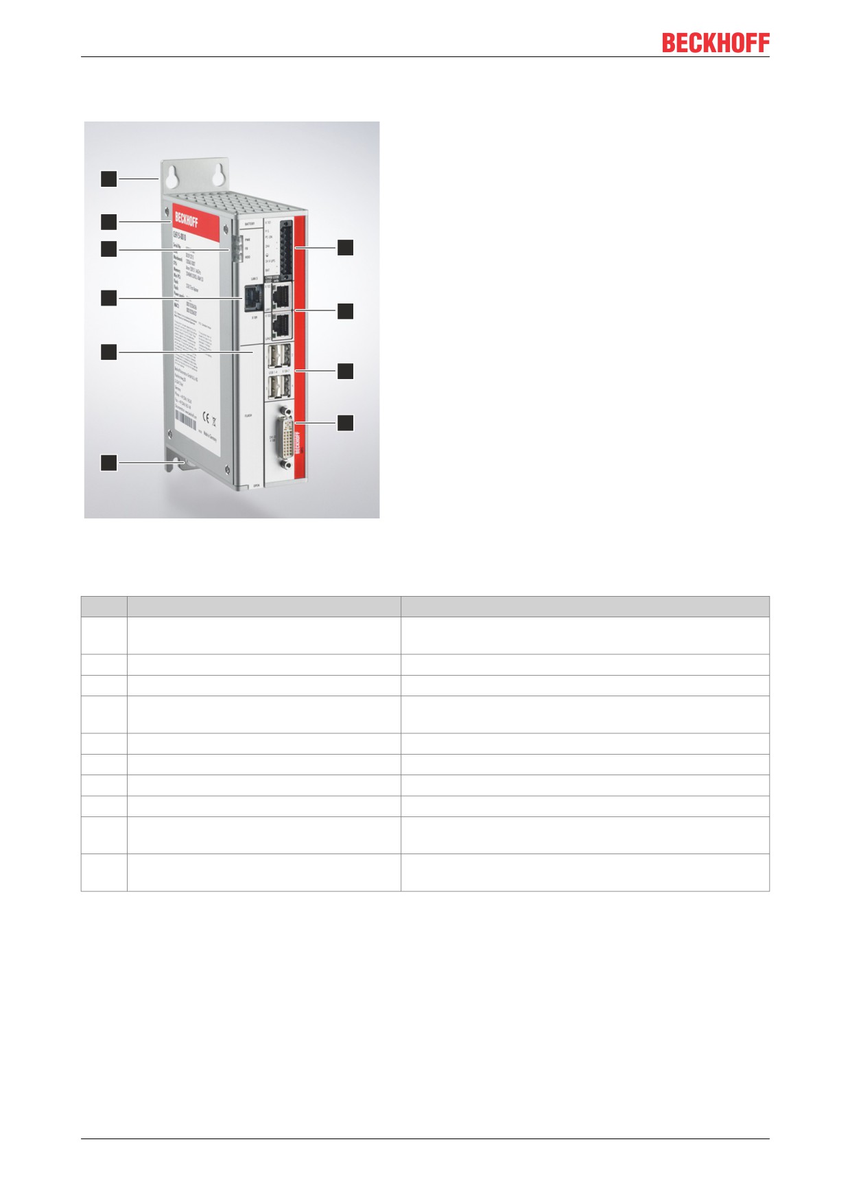
Fig. 1: C6915_structure
Table 1: Key: C6915 structure
No.
Component
Description
1
Mounting plate
Plate for mounting the Industrial PC by its the rear side in
the control cabinet
2
Name plate
Information on the equipment of the Industrial PC
3
Status LEDs
Status display for power, fieldbus, hard disk
4
Optional additional Ethernet RJ45
Connection of the Industrial PC to a 100/1000BASE-T
interface (X109)
network
5
Front flap
Access to battery and storage media
6
Grounding screw
Functional earthing of the Industrial PC
7
DVI interface (X108)
Connection of a DVI-capable monitor
8
USB interfaces (X104 - X107)
Connection of peripheral devices
9
RJ45 Ethernet interfaces (X102, X103)
Connection of the Industrial PC to a 100/1000BASE-T
network or EtherCAT
10
Power supply (X101)
Connection of the power supply, protective earth and
external wiring
10
Version: 2.5
Product overview
3.2
Interface description
The basic version of the C6915 has the following interfaces:
• Power supply (X101)
• Ethernet RJ45 (X102, X103)
• USB (X104 - X107)
• DVI (X108)
3.2.1
Power supply
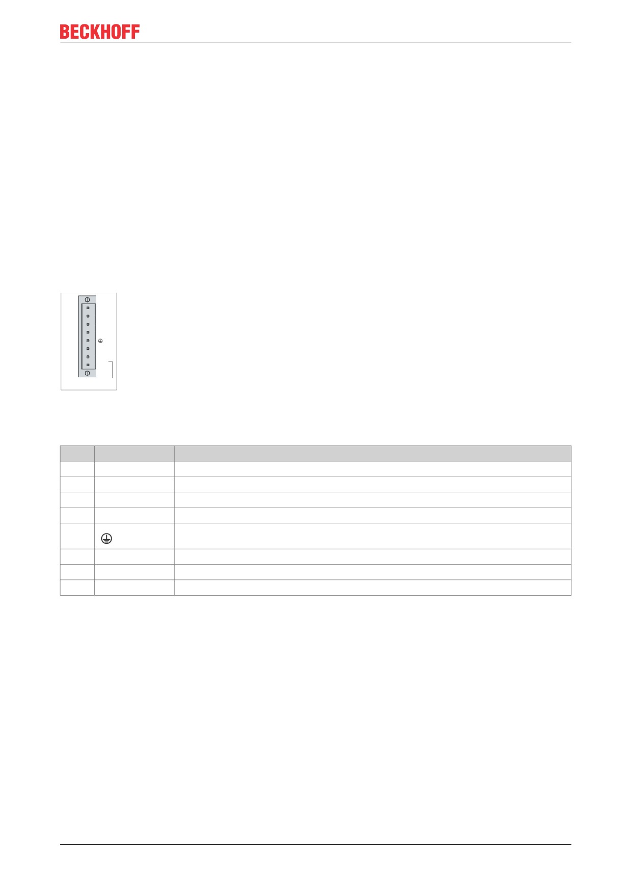
The Industrial PC is supplied with a rated voltage of 24 V. The 8-pin voltage socket (X101) is used for
connection to the power supply and the external wiring of the Industrial PC. The main supply voltage is
applied between PIN 5 (-24 V) and PIN 6 (+24 V) of the socket. If the Industrial PC is equipped with an
integrated uninterruptible power supply (UPS), an external battery pack can additionally be connected to PIN
1 and PIN 2.
8
P-S
PC-ON
+
24V
-
X101
24V UPS
+
BAT
1
-
C9900 U330
U332 only
Fig. 2: C6915_Voltage socket pin numbering
Table 2: Voltage socket pin assignment
Pin
Signal
Description
8
P-S
Power Status output, minus is the negative pole of the supply voltage
7
PC ON
Input PC_ON
6
+ 24 V
Positive pole Supply voltage 24 V
5
-
Negative pole Supply voltage 24 V
4
Protective earth
3
24 V UPS
24 V UPS output 2.5 A, minus is - BAT
2
+ BAT
Positive pole of the battery pack
1
- BAT
Negative pole of the battery pack
Version: 2.5
11
Product overview
3.2.2
Ethernet RJ45
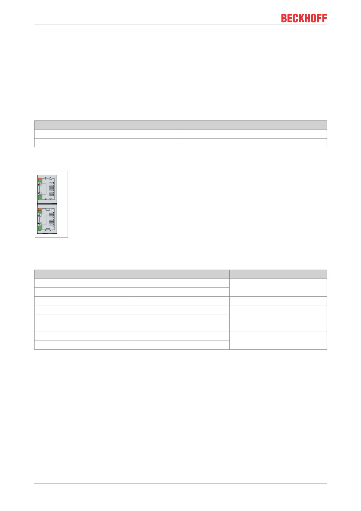
The C6915 has two Gigabit LAN ports (X102, X103). The 100Base-T and 1000Base-T Ethernet standards
enable the connection of corresponding network components and data rates of 100/1000 Mbit/s. The
required speed is selected automatically.
The RJ45 connection technology with twisted-pair cables is used. The maximum length of the cable
connection is 100 m.
The controllers are used as follows, based on the device generations:
Table 3: Controller classification based on device generations
Generation
Controller
C6915-0010
Intel® i210 for LAN1 and LAN2
C6915-0020
Intel® i210 for LAN1 and LAN2
The Ethernet port i210 connected via PCIe is usually suitable for cycle times <= 1 ms and for distributed
clock applications with EtherCAT.
X102
1
LAN1
8
1
LAN2
8
X103
Fig. 3: C6915_Ethernet interface pin numbering
Table 4: Ethernet interface pin assignment
Pin
Signal
Description
1
T2 +
Pair 2
2
T2 -
3
T3 +
Pair 3
4
T1 +
Pair 1
5
T1 -
6
T3 -
Pair 3
7
T4 +
Pair 4
8
T4 -
The LEDs of the LAN interfaces indicate the activity and the speed of the data transfer (Mbit/s). The lower
LED indicates whether the interface is connected to a network. If this is the case, the LED lights up green.
The LED flashes when data transfer is in progress.
The upper LED indicates the speed of the data transfer. If the speed is 100 Mbit/s the LED is orange, at
1000 Mbit/s it is green
12
Version: 2.5
Product overview
3.2.3
USB
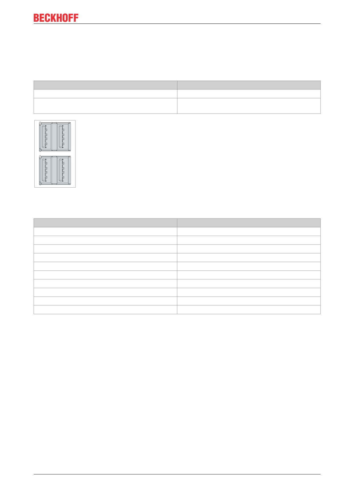
The Industrial PC has four USB interfaces (X104-X107). They are used to connect peripheral devices with
USB interfaces. The following table shows the interface assignment based on the device generation:
Table 5: USB interfaces based on device generation
Generation
USB interfaces
C6915-0010
4x USB 2.0
C6915-0020
2x USB 3.0
2x USB 2.0
5
4
5
4
6
6
3
3
1
7
7
2
2
2
8
8
9
1
9
1
X104-107
5
4
5
4
6
6
3
3
3
7
7
4
2
2
8
8
9
1
9
1
Fig. 4: C6915_USB interface pin numbering
Table 6: USB interface pin assignment
Pin
Connection
Shell
Shield
1
Vbus
2
D -
3
D +
4
GND
5
StdA_SSRX -
6
StdA_SSRX +
7
GND_DRAIN
8
StdA_SSTX -
9
StdA_SSTX +
For USB 2.0 only the first four pin assignments are relevant.
Version: 2.5
13
Product overview
3.2.4
DVI
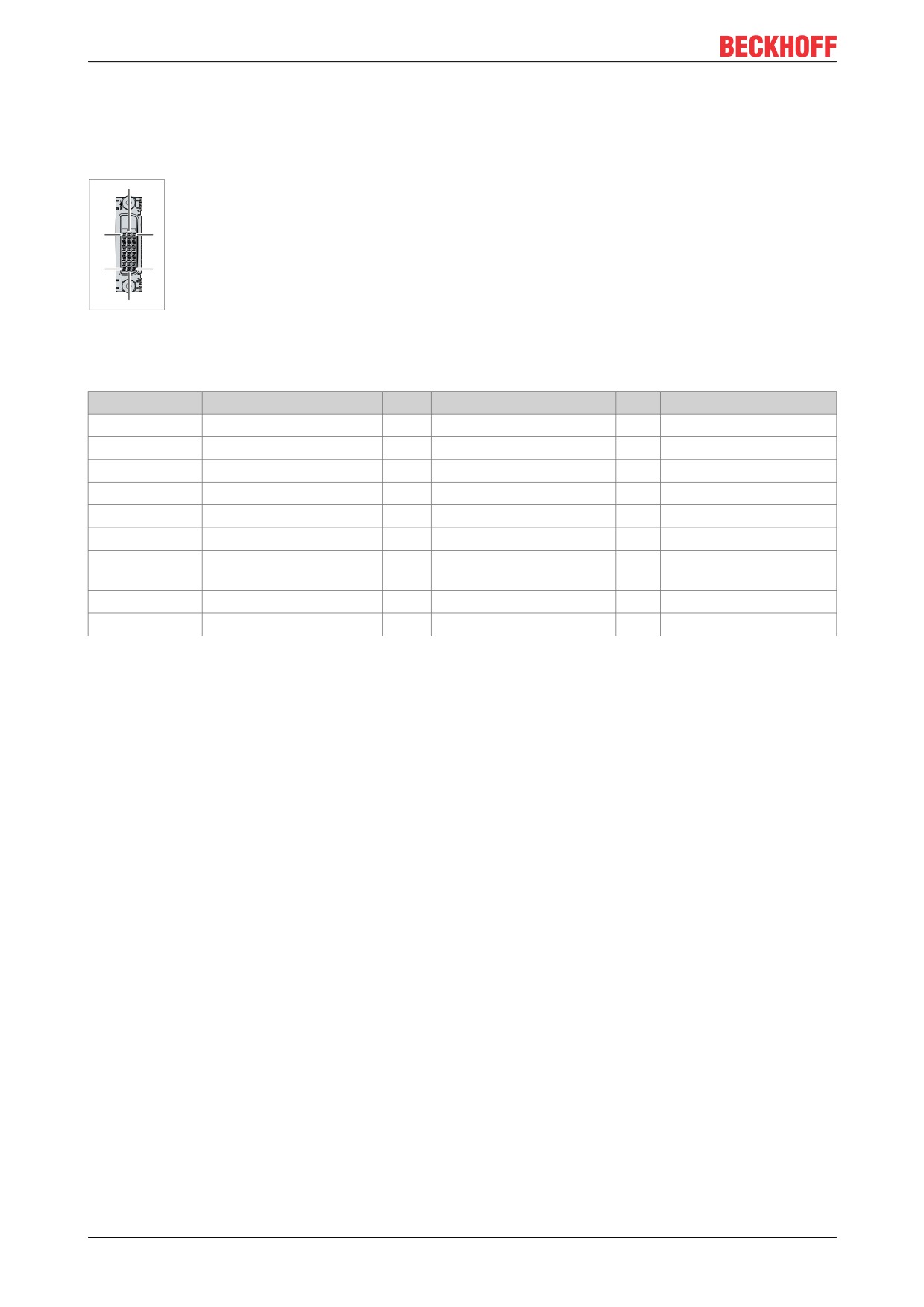
The Industrial PC has a DVI connection (X108), to which a DVI-capable monitor can be connected. Only
digital signals are transmitted.
16
X108
8
24
1
17
9
Fig. 5: C6915_DVI interface
Table 7: DVI interface pin assignment
Pin
Connection
Pin
Connection
Pin
Connection
1
TDMS Data 2 -
9
TDMS Data 1 -
17
TDMS Data 0 -
2
TDMS Data 2 +
10
TDMS Data 1 +
18
TDMS Data 0 +
3
TDMS Data 2/4 Shield
11
TDMS Data 1/3 Shield
19
TDMS Data 0/5 Shield
4
not connected
12
not connected
20
not connected
5
not connected
13
not connected
21
not connected
6
DDC Clock
14
+ 5V Power
22
TDMS Clock Shield
7
DDC Data
15
Ground (+ 5 V, Analog H/
23
TDMS Clock +
V Sync)
8
Analog Vertical Sync
16
Hot Plug Detect
24
TDMA Clock -
C5
GND
14
Version: 2.5
Product overview
3.3
Status LEDs
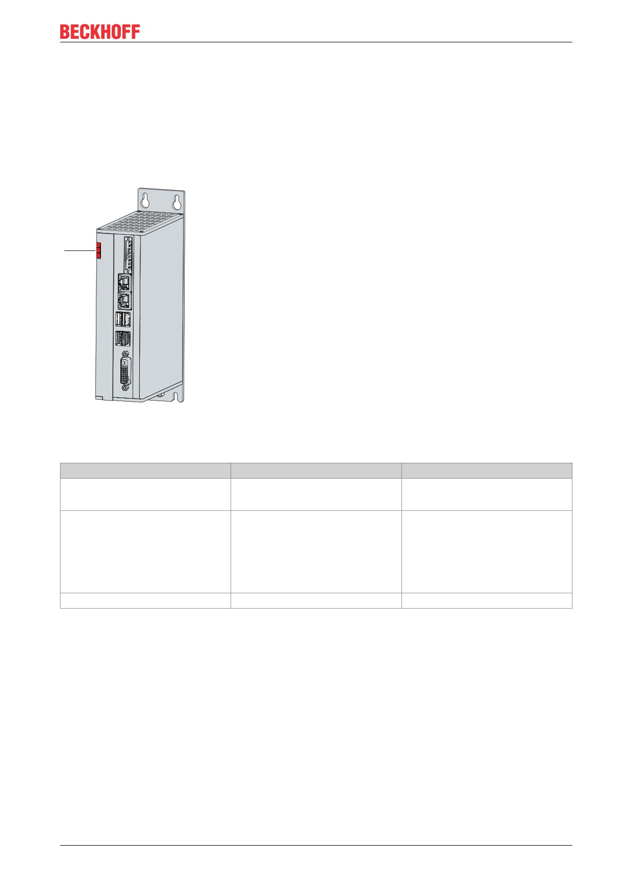
The Industrial PC has three status LEDs: PWR, FB, HDD. They provide information on the following aspects:
• the status of the power controller
• the fieldbus status
• the hard disk activity
The figure shows where the LEDs are located on the Industrial PC.
Fig. 6: C6915 Status LEDs
Table 8: Meaning of the Status LEDs
LED
Color/flashing interval
Meaning
PWR (Power)
green
Computer on
off
Computer off
FB (fieldbus)
red
TwinCAT Stop
blue
TwinCAT Config
blue/red flashing
TwinCAT Config (fieldbus error)
green
TwinCAT Run
green/red flashing
TwinCAT Run (fieldbus error)
HDD (hard disk)
red
Accessing storage media
Version: 2.5
15
Product overview
3.4
Name plate
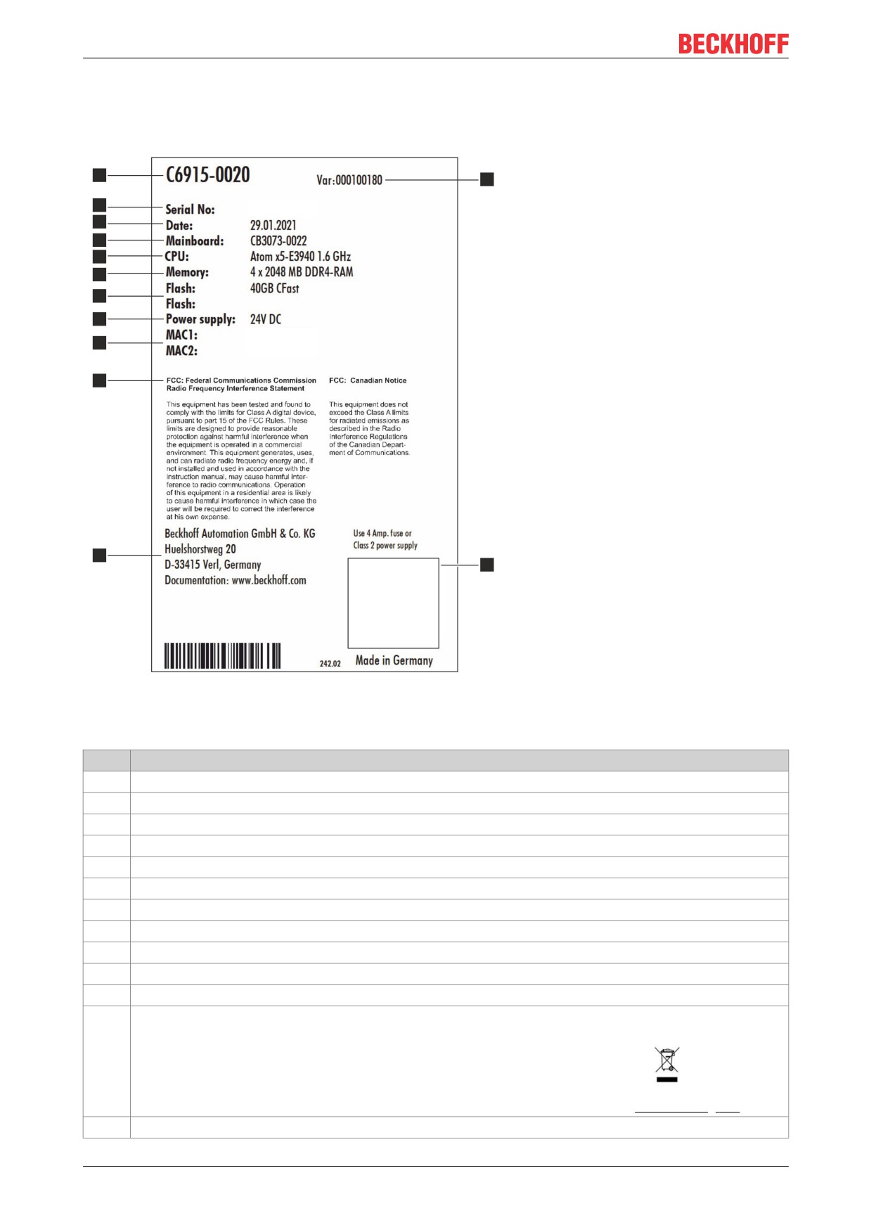
The name plate provides information on the equipment fitted to the Industrial PC.
1
13
2
xxxxxxxx
3
4
5
6
7
8
xxxxxxxxxxxxx
9
xxxxxxxxxxxxx
10
11
12
Fig. 7: C6915_Name plate example
Table 9: Key: name plate C6915
No.
Description
1
Model: The last four digits indicate the device generation.
2
Serial number (BTN)
3
Date of manufacture
4
Mainboard
5
CPU
6
RAM
7
Storage media
8
Power supply unit: 24 VDC
9
MAC addresses of the Ethernet interfaces (X102, X103)
10
FCC approval
11
Address of the vendor
12
Symbols
Note: Here are the symbols applicable to the device such as CE, EAC, UKCA,
. The
approvals of your device can be found on the name plate and in chapter 10.2 Approvals [} 41].
13
Variant number: Commercial number of the order code including ordering options
16
Version: 2.5
Commissioning
4
Commissioning
To be able to use the Industrial PC, you must first commission it. The first step is to transport the device to is
operating location and unpack it. This is followed by installing the device in the control cabinet, connecting
the cables and the power supply and finally switching on the Industrial PC.
4.1
Transport and unpacking
Note the specified transport and storage conditions (see Chapter 9, Technical data [} 39]).
Despite the robust design of the unit, the components are sensitive to strong vibrations and impacts.
Transporting a control cabinet with a built-in PC can result in excessive impact on the Industrial PC. During
transport the device must therefore be protected from excessive mechanical stress. Appropriate packaging
of the Industrial PC, in particular the original packaging, can improve the vibration resistance during
transport.
NOTE
Hardware damage due to condensation
Unfavorable weather conditions during transport can cause damage to the device.
• Protect the device against moisture (condensation) during transport in cold weather or in case of ex-
treme temperature fluctuations.
• Do not put the device into operation until it has slowly adjusted to the room temperature.
• Should condensation occur, wait for about 12 hours before switching the device on.
Unpacking
Proceed as follows to unpack the unit:
1. Remove packaging.
2. Keep the packaging for possible future transport.
3. Check your delivery for completeness by comparing it with your order.
4. Check the contents for visible shipping damage.
5. In case of discrepancies between the package contents and the order, or in case of transport damage,
please inform Beckhoff Service (see Chapter 10.1 Service and support [} 40]).
Version: 2.5
17
Commissioning
4.2
Installation in the control cabinet
NOTE
Incorrect installation
Mounting the device in a way that deviates from the documentation can impair its functionality.
• Mount the device only in the orientations shown in the documents.
The C6915 Industrial PC is designed for installation in control cabinets in machine and plant technology.
Please observe the environmental conditions prescribed for the operation (see Chapter 9 Technical data
[} 39]).
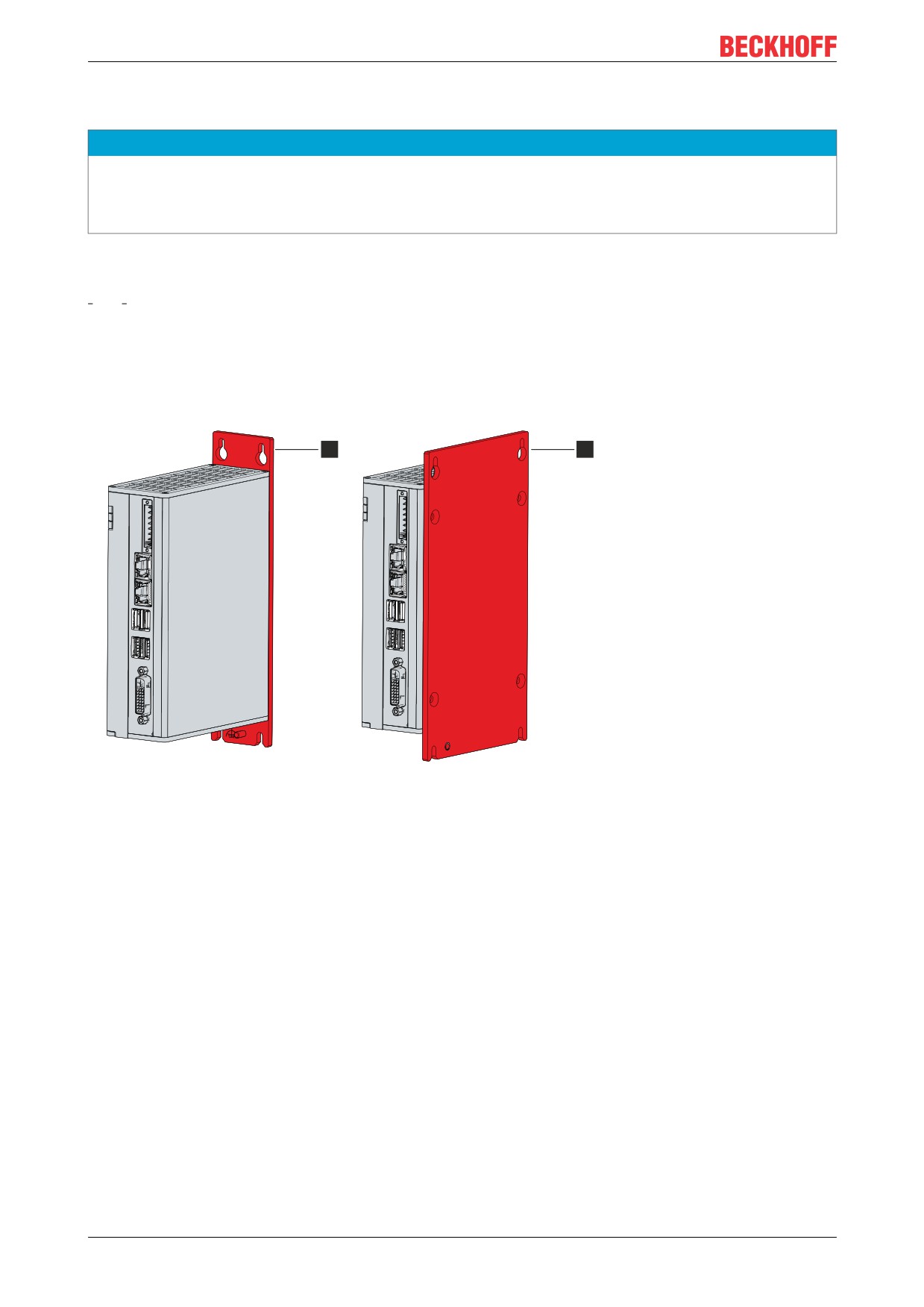
Using different mounting plates, you can align the cable entry based on the application requirements.
Figure 8 shows the two available mounting plates: the standard mounting plate 1 and the optional mounting
plate 2. Mounting plate 1 in mounted on the rear panel of the Industrial PC and mounting plate 2 on the right-
hand side panel. In both cases, four M4 x 8 countersunk head Philips screws are used for mounting.
1
2
Fig. 8: C6915_Mounting plates
In the basic equipment version, the Industrial PC is delivered with mounting plate 1 already mounted as
shown in fig. 8. Mounting plate 2 is not included in the scope of delivery. You can choose the following
ordering options:
• C9900-M653: Mounting plate on the side panel instead of on the rear panel
18
Version: 2.5
Commissioning
4.2.1
Dimensions
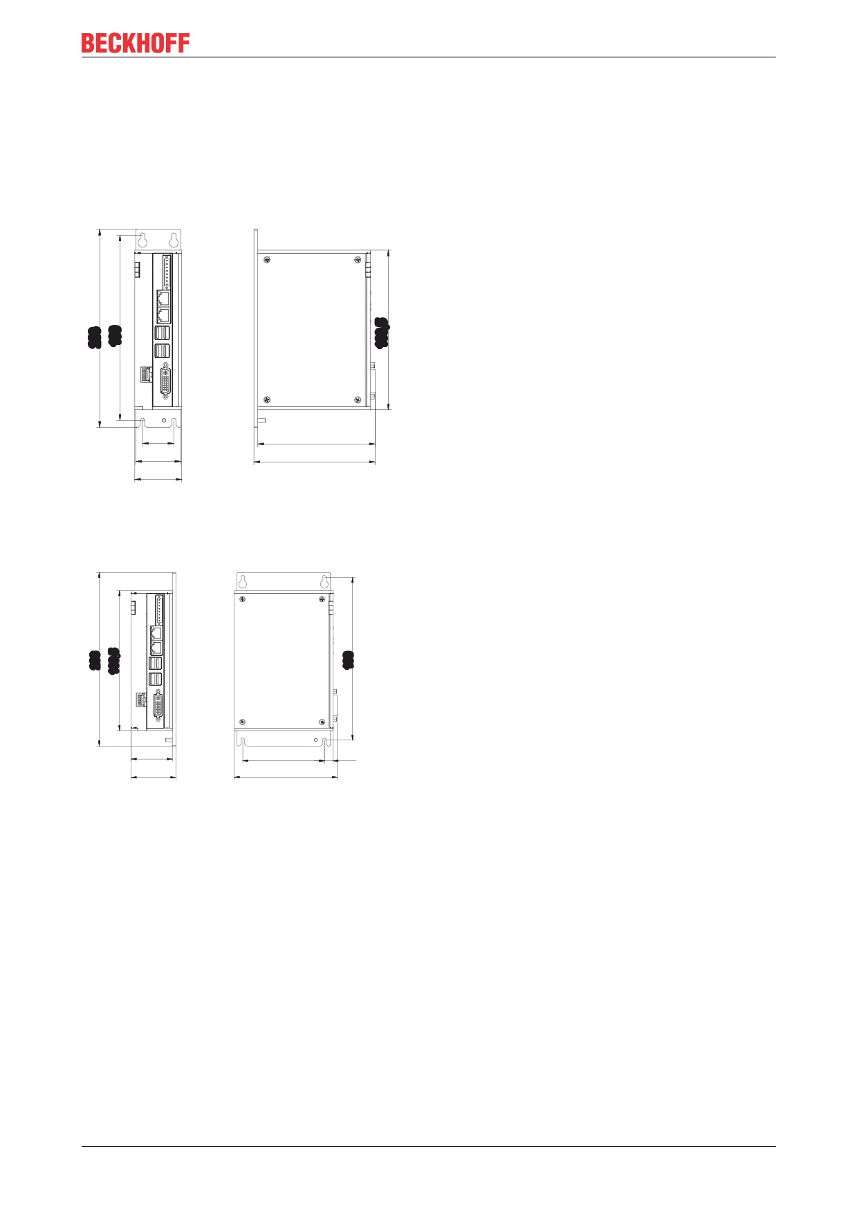
The dimensions of the Industrial PC and the mounting plate are used to prepare the control cabinet and to
mount the device correctly in the control cabinet.
All dimensions are in mm.
Figure 9 illustrates the dimensions of the Industrial PC with mounting plate 1.
32
120,3
46
124,3
48
Fig. 9: C6915_Dimensions with mounting plate 1
Figure 10 illustrates the dimensions of the Industrial PC with mounting plate 2.
48
95,2
10
52
120,3
Fig. 10: C6915_Dimensions with mounting plate 2
Version: 2.5
19
Commissioning
4.2.2
Installation in the control cabinet
NOTE
Extreme environmental conditions
Extreme environmental conditions can cause damage to the device.
• Avoid extreme environmental conditions.
• Protect the device against dust, moisture and heat.
• Do not cover the device's ventilation grille.
When installing in the control cabinet, note that there must be 5 cm of free space above and below the
device for ventilation.
Mounting via mounting plates
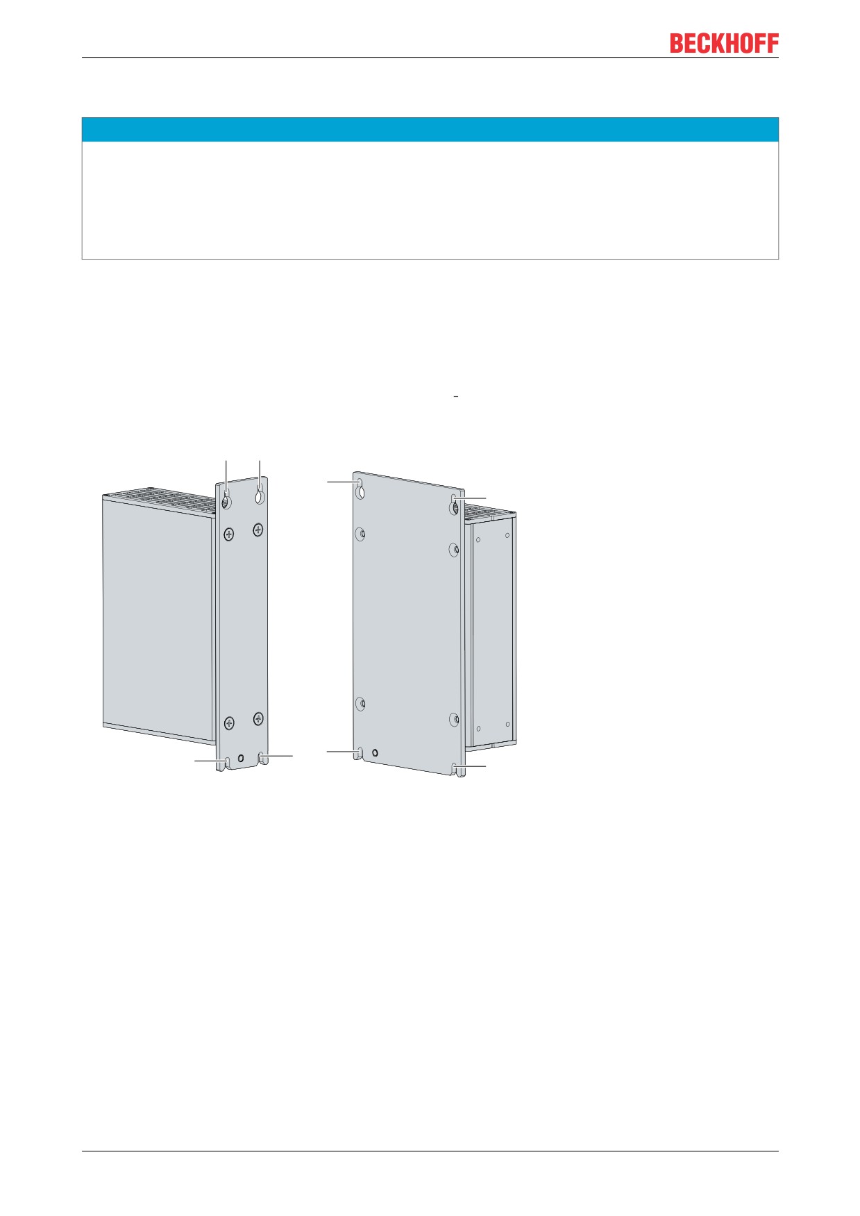
In order to mount the Industrial PC by its rear or side panel in the control cabinet using the mounting plates,
the control cabinet must be equipped with drill holes for the fastening screws corresponding to the
dimensions of the PC (see chapter 4.2.1 Dimensions [} 19]). You need M4 screws for mounting.
After you have drilled the holes for the fastening screws in the control cabinet, you can mount the Industrial
PC in the control cabinet with the mounting plates.
Fig. 11: C6915_Control cabinet installation
To install the Industrial PC in the control cabinet, follow the steps below:
1. Place the fastening screws in the drill holes in the rear panel of the control cabinet.
2. Hang the PC on the screws at the marked places on the mounting plate (see fig. 11).
3. Tighten the fastening screws.
You have successfully installed the Industrial PC in the control cabinet.
20
Version: 2.5
Commissioning
4.3
Connecting the Industrial PC
CAUTION
Risk of electric shock
Dangerous touch voltages can lead to electric shock. To avoid electric shock, observe the following:
• Never connect or disconnect the device cables during a thunderstorm.
• Provide protective earthing for handling the device.
To prepare the Industrial PC for operation, it must be connected. The first step is to ground the device. Then
you can connect the cables and the power supply.
An external power supply unit is required to supply 24 V DC (-15 %/+20 %) for operating the device.
Wire the Industrial PC in the control cabinet in accordance with the EN 60204-1:2006 standard on Protective
Extra Low Voltage (PELV) so that one side of the circuit or a point on the power source of this circuit is
connected to the protective conductor system.
Version: 2.5
21
Commissioning
4.3.1
Installing the supply cable
Mount the cable for the power supply to the Industrial PC using the material provided for the connector
assembly. It consists of a 8-pin connection strip and a strain relief housing with cable tie.
Installing the supply cable
First mount the plug on the cable as follows:
1. Remove the insulation from the cable ends (8-9 mm).
2. Screw the cable ends into the 8-pin connection strip. For the pin assignment of the connector, see
Chapter 3.2.1 Power supply [} 11].
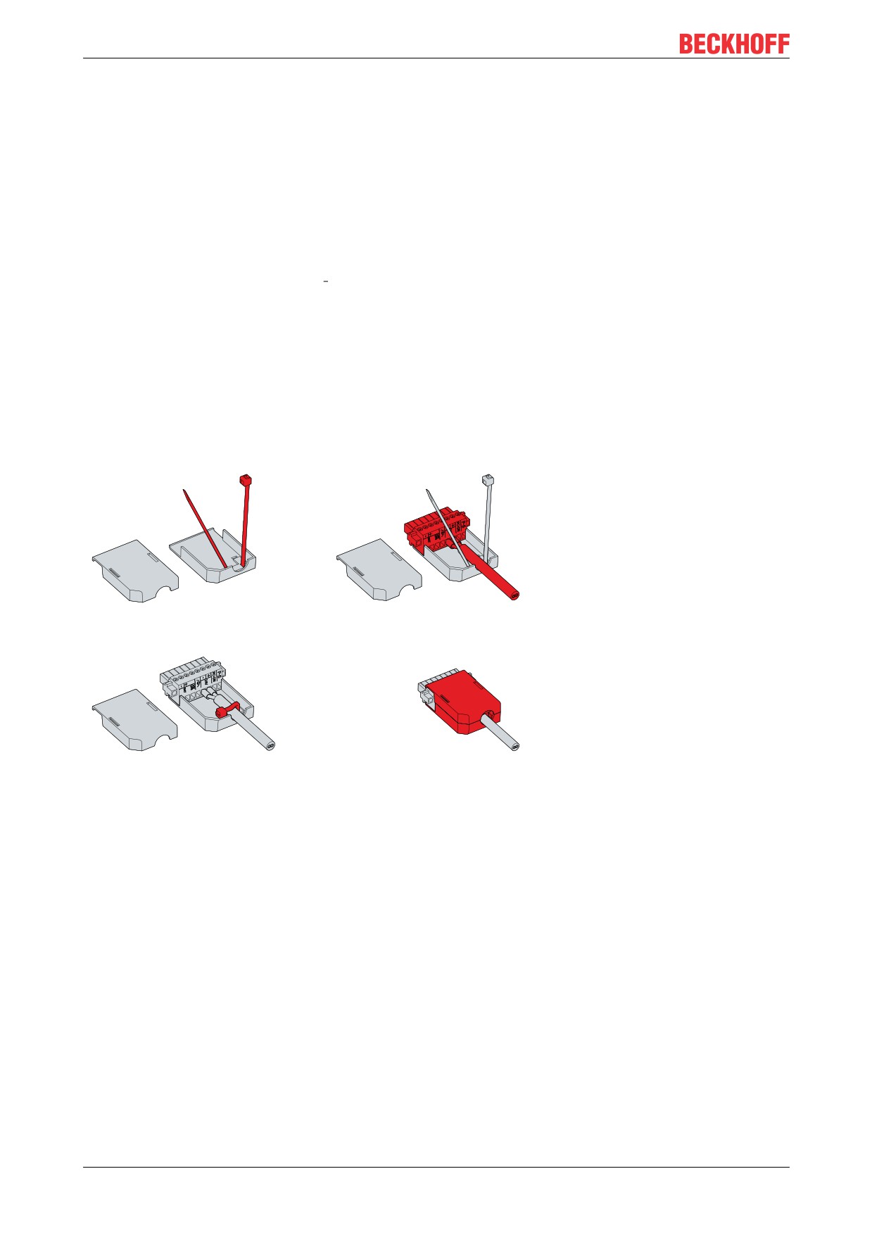
Assembly of the strain relief housing
Now mount the strain relief housing on the already connected connector and supply cable as shown in fig.
12:
1. Thread the cable tie into the lower part of the strain relief housing (section A).
2. Insert the connection strip into the lower part of the strain relief housing (section B).
3. Tighten the cable tie and remove the plastic tab (section C).
4. Attach the upper part of the strain relief housing by snapping it onto the lower part (section D).
A
B
C
D
Fig. 12: C6915_Mounting the strain relief housing
22
Version: 2.5
Commissioning
4.3.2
Grounding of the Industrial PC
Potential differences are minimized and electrical currents are diverted to the ground through grounding or
potential equalization of electronic devices. This is to prevent dangerous touch voltages and electromagnetic
interference.
At the lower end of the Industrial PC mounting plate there is an grounding screw (see also chapter 3.1
Structure [} 10]), via which the functional earth of the PC can be connected. Use cables with a cross-section
of at least 4 mm2 to connect the protective conductor.
Protective earth
Establish the low-resistance protective earth of the Industrial PC via the voltage connection, thus avoiding
dangerous contact voltages. There is a pin in the voltage socket for the protective earth (PE).
EMC
NOTE
Hardware damage due to electromagnetic interference
Using the Industrial PC without functional earthing can lead to hardware damage due to electromagnetic in-
terference.
• Only use the device with functional earthing.
Electromagnetic compatibility (EMC) of the industrial PC includes on the one hand not affecting other
devices and equipment by electromagnetic interference and on the other hand not being disturbed by
electrical or electromagnetic effects itself.
For this purpose, the Industrial PC must comply with certain protection requirements. The Industrial PC has
EMC interference immunity according to EN 61000-6-2. The EMC interference emission of the device meets
the requirements of EN 61000-6-4.
The functional earth is necessary for the EMC of the device. The functional earth is established by
connecting the grounding point on the PC mounting plate to the central grounding point of the control cabinet
in which the PC is installed.
Version: 2.5
23
Commissioning
4.3.3
Connecting cables and power supply
NOTE
Incorrect connection procedure
Incorrect procedure when connecting the cables and the power supply can cause hardware damage.
• Follow the documented procedure for connecting the cables and the power supply.
• Always connect the cables first and only then switch on the power supply.
• Please read the documentation for the external devices prior to connecting them.
NOTE
Connection of incorrect battery packs
The connection of incorrect battery packs can lead to damage to the Industrial PC and to the battery packs.
• Connect only Beckhoff battery packs to your Industrial PC.
Connecting cables
The connections are located in the front of the Industrial PC and are documented in Chapter 3.1 Structure
[} 10].
Make sure that you first ground the PC (see Chapter Grounding of the Industrial PC [} 23]) and then plug in
all data transfer cables.
Connecting the power supply
Cables with a maximum cable cross-section of 1.5 mm2 must be used for connecting the power supply. To
achieve the lowest possible voltage drop on the supply line, we recommend connecting the maximum
possible cross-section. In case of larger distances between the power source and the PC, take into account
the voltage drop in relation to the cable cross-section as well as fluctuations in your supply voltage in order to
ensure that the voltage at the power supply unit does not fall below 22 V.
Proceed as follows to connect the 24 VDC power supply unit:
1. Check the correct voltage of your external power supply.
2. Install the power cable.
3. Plug the power cable into the voltage socket of the Industrial PC.
4. Screw the power cable to the voltage socket of the Industrial PC.
5. Connect the PC to your external 24 V power supply.
6. Switch on the 24 V power supply.
7. Measure the voltage on the power supply plug of the PC.
External battery pack and UPS output
If you ordered your device with an integrated UPS, then you can connect an external battery pack and install
it on a DIN rail near to the PC. Use only Beckhoff battery packs for this:
• C9900-U330: Universal battery pack for PCs and Panel PCs in any configuration
• C9900-U332: Battery pack for PCs with low power consumption without using the UPS output on the
PC
When using the C9900-U330 battery pack, you can use the UPS output of the power supply unit (UPS
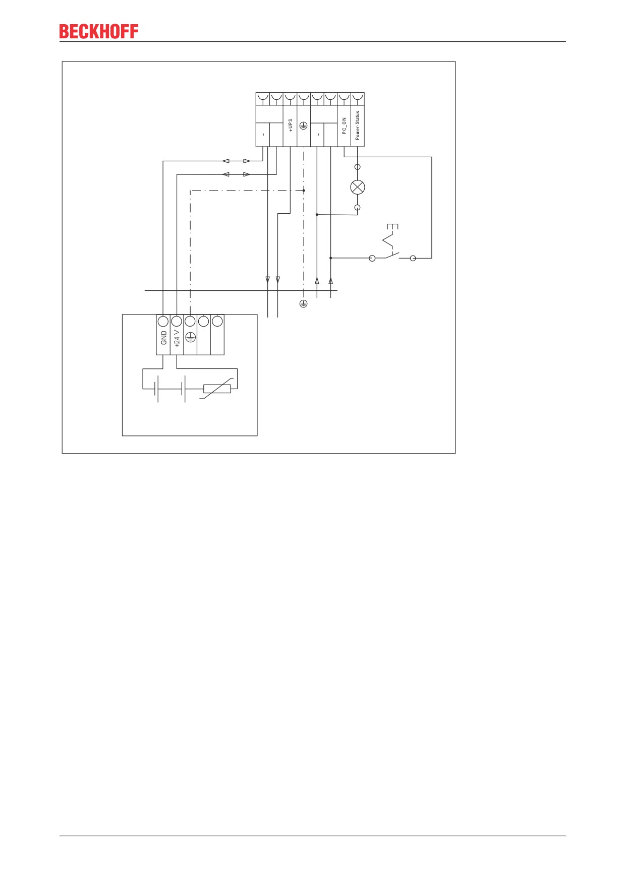
Output). The method of connecting different components can be taken from the wiring diagram in fig. 13.
24
Version: 2.5
Commissioning
1
2
3
4
5
6
7
8
Battery
Power
24 V
24 V DC
+
+
X2
X1
ext. switch
N0
N0
X1
X2
L max = 10 m
1,5 mm / AWG142
0 V
22-30 V DC
1
2
-
+
UPS Output
PTC
24 V/3,4 Ah
30 V/9 A
C9900-U330 battery pack
Fig. 13: C6915_Wiring diagram
So that the Industrial PC still has a monitor output in case of a power failure, a Control Panel can be
connected to the UPS output of the power supply unit. Even after a power failure there is a voltage of 24 VDC
between the UPS output and the negative pole of the battery pack. The maximum load is 1.4 A (max. 2.5 A
from year of manufacture 2016).
Once the PC has been de-energized via the UPS software, the UPS output is switched to 0 V. A connected
panel is switched off.
Version: 2.5
25

Commissioning
4.4
Switching the Industrial PC on and off
First switching on and driver installation
NOTE
Public networks
Connecting the PC to public networks without additional protective measures can compromise the safety of
the device.
• Protect the PC before connecting it to public networks.
The Industrial PC is started when the system is switched on or when the power supply is connected.
When you switch on the Industrial PC for the first time, the pre-installed operating system (optional) will be
started. For any additional hardware you have connected, you have to install the drivers yourself afterwards.
In addition, the Beckhoff Device Manager starts automatically. The Device Manager is a software from
Beckhoff that supports you in configuring the PC.
If you have ordered the PC without an operating system, you must install this and the driver software for the
additional hardware you have connected and for the devices in the PC yourself. Please follow the
instructions in the documentation for the operating system and the additional devices.
Switching off the Industrial PC
NOTE
Data loss due to running software
Switching off the Industrial PC before the running software is terminated and the operating system is shut
down can lead to data loss.
• Quit the running software and shut down the operating system before switching off the PC.
NOTE
Shortened battery life due to switching off the power supply
If the power supply is simply switched off, the operating system shuts down via the battery. With daily use,
this significantly shortens the life of the battery.
• Avoid switching off the power supply before shutting down the operating system.
• Use the Beckhoff concept (see below) to shut down the operating system in a battery-friendly manner.
When the system is switched off or disconnected from its own power supply, the Industrial PC is also
switched off.
If you have an Industrial PC with a UPS and simply switch off the power supply, the operating system shuts
down via the battery. With frequent use, this shortens the life of the battery.
To shut down the operating system properly, you can install an additional ON/OFF switch next to the
machine's main switch to turn the machine on and off. The main switch can thus remain switched on in
principle and thus ensures that the PC is still supplied with power during the shutdown of the operating
system.
If 24 V is then applied to the input PC_ON via a switch, the operating system shuts down properly. The
PC_ON signal is inverted, i.e. the operating system shuts down when 24 V is applied.
Once the operating system has shut down, the PC power supply unit sets the output power status from 24 V
to 0 V. This indicates that the shutdown is complete and you can turn off the power supply. Via the output,
you can switch, for example, a contactor that switches off the entire system. The maximum load for the
Power Status output is 0.5 A and a suitable fuse should be provided.
You can assign different access rights to all users in the operating system and in the application software.
Since there is a risk of data loss if the Industrial PC is switched off incorrectly, assign the rights advisedly. A
user who is not allowed to terminate the software should not be allowed to switch off the Industrial PC.
UPS software components
26
Version: 2.5
Commissioning
To operate the power supply unit as a UPS, the UPS driver software with the corresponding drivers must be
installed on the Industrial PC. The software and drivers are already installed on delivery of the PC with
operating system. Otherwise, you will have to install them yourself.
You can obtain the software and drivers either online for download via the following link: https://
download.beckhoff.com/download/software/Industrial_PC/OS_Support/Driver_DVD or you can contact
Beckhoff Service (service@beckhoff.com), which will provide you with the software and drivers. The driver
software comes with a detailed help function. Call up the help files either directly from the configuration tab
by clicking the Help button or start the file under Start > Programs > Beckhoff > UPS software components.
The method of communication between your PC and the UPS depends on the PC generation. The following
table provides information about the method of communication according to the device generation:
Table 10: UPS communication
Device generation
UPS communication method
C6915-0010
Serial communication
C6915-0020
Communication via BIOS API
In the case of serial communication, all you need is the UPS driver. If the communication takes place via the
BIOS API, you also need the Beckhoff Automation Device Driver in addition to the UPS driver.
Version: 2.5
27
Beckhoff Device Manager
5
Beckhoff Device Manager
The Beckhoff Device Manager enables detailed system diagnostics with uniform secure access to the
existing hardware and software components. System data is recorded, analyzed and evaluated during
operation. The data helps to detect deviations at an early stage and prevent PC downtime.
The Beckhoff Device Manager always starts automatically after the Industrial PC has been booted. In
addition, you have the option of manually starting the previously closed Device Manager at any time.
The Industrial PC is delivered with predefined access data as standard:
• User name: Administrator
• Password: 1
You also have the option of using the Beckhoff Device Manager to remotely configure the Industrial PC via a
web browser. More detailed information is available in the Beckhoff Device Manager manual.
First start Beckhoff Device Manager
When your Industrial PC is booted for the first time, the Beckhoff Device Manager also starts automatically
for the first time. The Security Wizard opens. This tells you that you should reset the default password set by
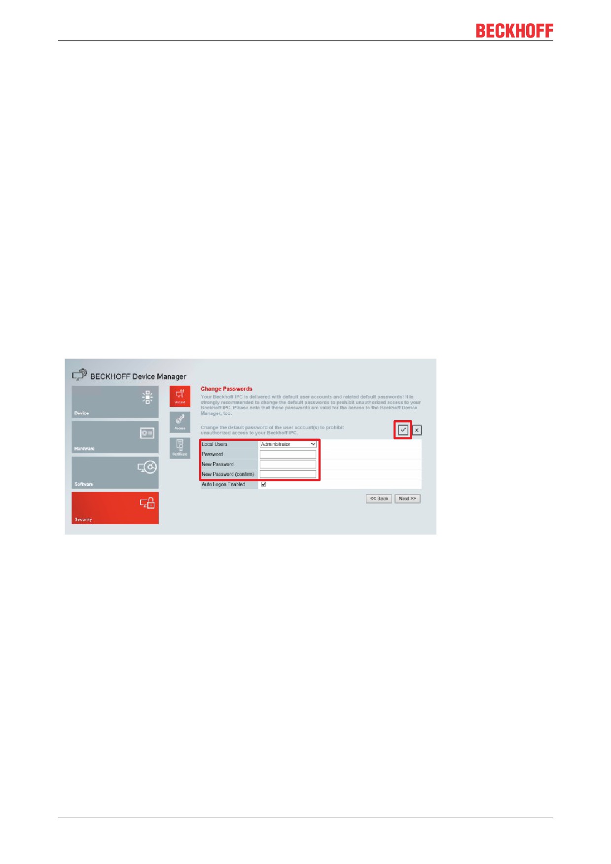
Beckhoff. Proceed as follows:
1. Click Next on the Security Wizard start page.
This will take you to the Change Passwords page:
Fig. 14: Beckhoff Device Manager - Change passwords
2. Enter the access data of the Device Manager on delivery.
3. Choose a secure new password. Instructions for choosing a secure password are given below.
4. Confirm the changes by clicking on the tick in the red box on the right.
5. Exit the Security Wizard to switch to the Device Manager start page:
28
Version: 2.5

Beckhoff Device Manager
Fig. 15: Beckhoff Device Manager - Start page
Navigate forward in the menu and configure the Industrial PC. Note that modifications only become active
once they have been confirmed. It may be necessary to restart the Industrial PC.
Manual start Beckhoff Device Manager
To start the Beckhoff Device Manager manually, proceed as follows:
1. Open a web browser locally on the Industrial PC.
2. Enter localhost/config in the web browser to start the Beckhoff Device Manager.
The Beckhoff Device Manager starts. The Security Wizard appears.
Secure passwords
Strong passwords are an important prerequisite for a secure system.
Beckhoff supplies the device images with standard user names and standard passwords for the operating
system. It is imperative that you change these.
Controllers are shipped without a password in the UEFI/BIOS setup. Beckhoff recommends assigning a
password here as well.
Please note the following:
• Passwords should be unique for each user and service.
• Only change passwords after an incident in which passwords have become known without
authorization.
• Train the device users in the use of passwords.
A secure password has the following characteristics:
• Password complexity: the password should contain capital and lower-case letters, numbers,
punctuation marks and special characters.
• Password length: the password should be at least 10 characters long.
Version: 2.5
29
Decommissioning
6
Decommissioning
NOTE
Hardware damage due to power supply
A connected power supply can cause damage to the Industrial PC during disassembly.
• Disconnect the power supply from the device before starting to disassemble it.
When taking the Industrial PC out of operation, you must first disconnect the power supply and cables. You
can then remove the device from the control cabinet.
If you do not want to continue using the Industrial PC, Chapter 6.2 Disassembly and disposal [} 31] provides
information on the correct disposal of the device.
6.1
Disconnecting the power supply and cables
CAUTION
Risk of electric shock
Disconnecting the Industrial PC during a thunderstorm can lead to electric shock.
• Never disconnect the cables from the device during thunderstorms.
Before you remove the Industrial PC from the control cabinet, you must follow the following steps:
1. Shut down the operating system.
2. Disconnect the Industrial PC from the power supply (see below).
3. Disconnect the data transfer cables between the Industrial PC and the connected devices (see below).
Disconnect the power supply
Proceed as follows to disconnect the power supply:
1. Disconnect the PC from your external 24 V power supply.
2. Unscrew the voltage connector and pull it out of the PC.
3. Dismantle the power cable if the plug is to remain with the PC.
Disconnecting cables
To disconnect the cables from the Industrial PC, proceed as follows:
1. Make a note of the wiring configuration, if you wish to restore it with another device.
2. Disconnect the data transmission cables from the Industrial PC.
3. Finally, disconnect the grounding strap.
30
Version: 2.5
Decommissioning
6.2
Disassembly and disposal
Before you can remove the Industrial PC from the control cabinet, you must first disconnect the power supply
and the cables (see Chapter 6.1 Disconnecting the power supply and cables [} 30]).
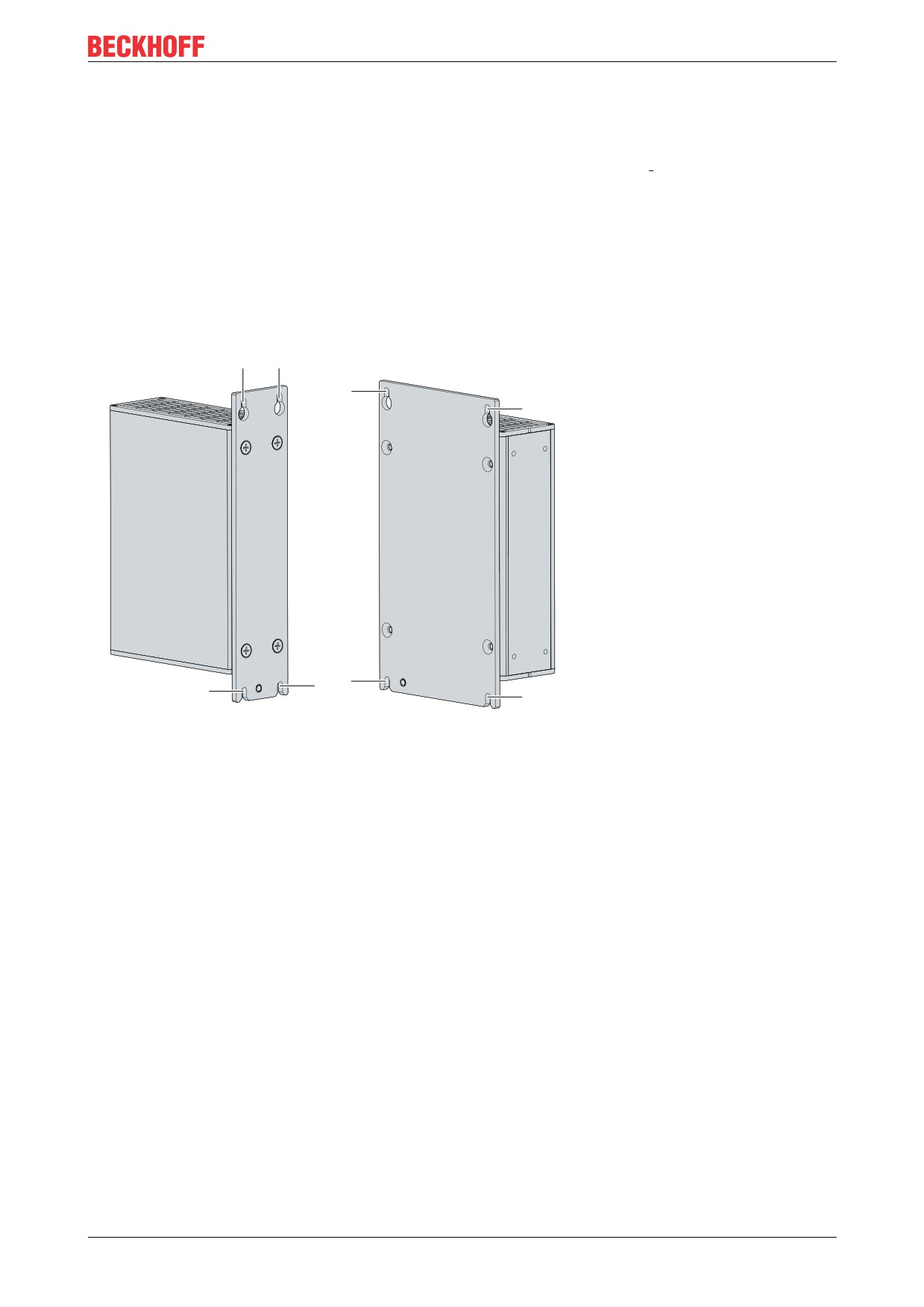
Disassembly via mounting plates
Proceed as follows to remove the Industrial PC with the corresponding mounting plate from the control
cabinet:
1. Loosen the fastening screws just enough so that they remain attached to the control cabinet.
2. Lift the PC far enough so that the mounting screws slip into the keyholes (see fig. 16).
3. Remove the PC from the control cabinet.
You have successfully disassembled the PC.
Fig. 16: C6915_Dismantling the control cabinet
Disposal of the Industrial PC
Be sure to observe the national electronic scrap regulations when disposing of the Industrial PC.
In order to dispose of the device, it must be removed and fully dismantled. Dispose of the components in the
following way:
• Send plastic parts (polycarbonate, polyamide (PA6.6)) for plastics recycling.
• Take metal parts to the metal recycling collection point.
• Electronic parts such as fans and circuit boards must be disposed of in accordance with national
electronic scrap regulations.
• Stick insulating tape over the poles of the CR2032 battery on the motherboard and dispose of the
battery via the local battery recycling.
Version: 2.5
31
Maintenance
7
Maintenance
CAUTION
Risk of electric shock
Working on the Industrial PC while it is live can lead to electric shock.
• Turn off the supply voltage before cleaning the device or replacing device components. Excluded from
this is the replacement of hard disks in RAID configuration and fan cartridges.
Maintenance measures increase the efficiency of the device by ensuring long-term functionality. Cleaning
and maintenance of certain device components and the replacement of other device components contribute
to this.
Repair
Only the manufacturer may repair the device. If a repair should be necessary, contact Beckhoff Service (see
Chapter 10.1 Service and support [} 40]).
7.1
Cleaning
NOTE
Unsuitable cleaning agents
The use of unsuitable cleaning agents can damage the device.
• Only clean the Industrial PC as specified.
It is essential to observe the following aspects when cleaning the Industrial PC:
• Make sure that no dust gets into the PC.
• Always keep the ventilation grilles free.
• Only use a vacuum cleaner to clean the PC. The Industrial PC does not have to be switched off for
this.
• Never use compressed air to clean the PC.
32
Version: 2.5
Maintenance
7.2
Maintenance
NOTE
Use of incorrect spare parts
The use of spare parts not ordered from Beckhoff Service can lead to unsafe and faulty operation.
• Only use spare parts that you have ordered from Beckhoff Service.
Beckhoff Industrial PCs are manufactured from components of the highest quality and robustness. They are
selected and tested for best interoperability, long-term availability and reliable function under the specified
environmental conditions.
Nevertheless, some components of the Industrial PC may be subject to a limited service life if they are
operated under certain conditions, such as more demanding ambient conditions during operation or during
storage, or if they are out of service for long periods of storage.
Beckhoff therefore recommends replacing some of the Industrial PC components after the time after which
predictions of the remaining service life of such components can no longer be reliably calculated.
These are the following components:
• Battery and battery pack
• Storage media
The following table provides recommendations for the regular, precautionary replacement of the PC
components:
Table 11: Replacement recommendations for PC components
Component
Recommendation for replacement intervals (years)
UPS battery pack
5 years
2.5-inch hard disk
5 years or after 20,000 operating hours at more than 40 °C or after
30,000 operating hours at less than 40 °C
3.5-inch hard disk
5 years, irrespective of the operating hours
Fan
7 years
Compact Flash, CFast or SSD
10 years
Motherboard battery
5 years
Beckhoff is excluded from liability in the event of possible damage occurring during maintenance work. In
order to avoid damage caused by electrostatic discharge when replacing device components, protective
measures are recommended. Below are some suggestions.
ESD protection
NOTE
Electrostatic discharge
The replacement of device components without ESD protection can lead to functional impairment and de-
struction of the device.
• If possible, apply ESD protection measures during maintenance work.
When working on electronic devices, there is a risk of damage due to ESD (electrostatic discharge), which
can impair the function or destroy the device.
Protect the Industrial PC and create an ESD-protected environment in which any electrostatic charges are
discharged to the ground in a controlled manner and charging is prevented.
An ESD-protected environment can best be created by setting up ESD protection zones. The following
measures serve this purpose:
• ESD-compliant floors with sufficient conductivity to the reference potential PE;
• ESD-compatible work surfaces such as tables and shelves;
• Wrist grounding strap, especially for sedentary activities;
Version: 2.5
33
Maintenance
• grounded and electrostatically dissipating equipment and operating materials (e.g. tools) within the
ESD protection zone.
If it is not possible to create an ESD protection zone, you can still protect the device against ESD damage.
For example, the following measures can be used:
• Use conductive mats connected to the ground potential as underlays.
• Dissipate possible charges from your own body by touching earthed metal (e.g. control cabinet door).
• Wear a wrist grounding strap.
• Only remove new electronic components from the ESD packaging (tinted plastic bag) after putting on
the wrist grounding strap.
• Do not walk around with electronic components in your hand if they are not in ESD packaging.
34
Version: 2.5
Maintenance
7.2.1
Access to device components
In order to be able to replace certain device components, you must first gain access to these components.
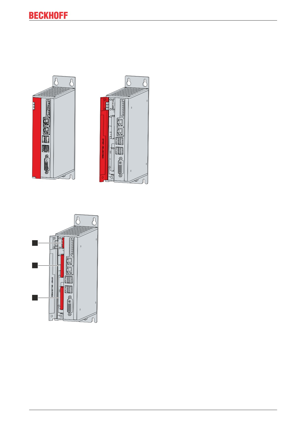
Access to battery and storage media
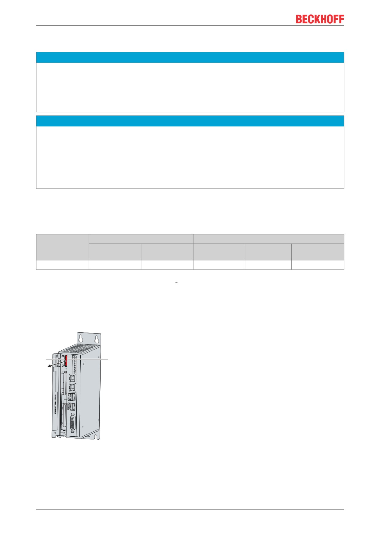
To get access to the battery and the storage media, open the front flap (see fig. 17).
Fig. 17: C6915_tool-less access to battery and storage media
You now have access to the battery (1) and storage media (2) (see Fig. 18).
1
2
2
Fig. 18: C6915 _Battery and storage media
Version: 2.5
35
Maintenance
7.2.2
Replacing the battery
NOTE
Incorrect battery type
Replace battery with R/C (BBCV2), Part. No. CR2032, rated 3 V only. Use of another battery may present a
risk of fire or explosion.
• Only replace the battery with a replacement battery from Beckhoff Service.
• When replacing the battery, make sure that the polarity is correct.
NOTE
Battery damage
Incorrect handling of the motherboard battery can damage it.
• Do not recharge the battery.
• Do not throw the battery on the fire.
• Do not open the battery.
• Protect the battery against direct sunlight and moisture.
The Industrial PC does not contain a lithium-ion battery. The motherboard battery is a CR2032 lithium-metal
cell. It is used to supply power to the clock integrated on the motherboard. If the battery is depleted or
missing, the date and time are displayed incorrectly.
Table 12: Technical data of the battery.
Battery type
Electrical properties (at 20 °C)
Dimensions
Nominal voltage
Nominal capac-
Diameter
Height
Weight
ity
CR2032
3.0 V
225 mAh
20.0 mm
3.20 mm
3.1 g
Chapter 7.2.1 Access to device components [} 35] shows how to access the battery.
To change the battery, proceed as follows:
1. Pull the battery out of the Industrial PC with needle-nose pliers.
2. Insert the new battery into the PC by hand. Pay attention to the correct polarity. The negative pole of
the battery must face the voltage socket of the industrial PC (see fig. 19).
+
-
Fig. 19: C6915_Battery change
To dispose of the battery, remove it, stick insulating tape over the poles and take it to the local battery
recycling.
36
Version: 2.5
Maintenance
7.2.3
Replacing the storage media
New storage media should only be obtained from Beckhoff Service (see Chapter 10.1 Service and support
[} 40]).
The old storage media must be disposed of in accordance with the national electronic waste regulations.
Data transfer before replacement
If you want to exchange a storage medium according to Beckhoff's recommendation, you must copy the data
from the old to the new storage medium. You can use the Beckhoff Service Tool (BST) for this purpose. The
BST is a graphical backup and restore program for Industrial PCs with a Windows operating system. You
can create an image of your operating system and use it to back up the operating system. You can then
restore the images created in this way. The BST is available on a bootable BST USB flash drive. This
includes Windows and a backup software. Select the size of the BST USB flash drive according to the size of
the backup copy of your operating system. You can then keep the flash drive as a backup copy. For this
purpose, the BST USB flash drives with SLC flash are designed for a particularly long data preservation. For
more information on the function of the BST, please refer to the corresponding documentation.
If your storage medium is defective and there is no backup, Beckhoff Service can provide you with a fresh
Windows image. For this to be possible, the Beckhoff IPC must already have been shipped with a valid
operating system license. When installing the fresh image, the applications must be reinstalled.
Replacing the CFast
Chapter 7.2.1 Access to device components [} 35] shows how you can access the CFast.
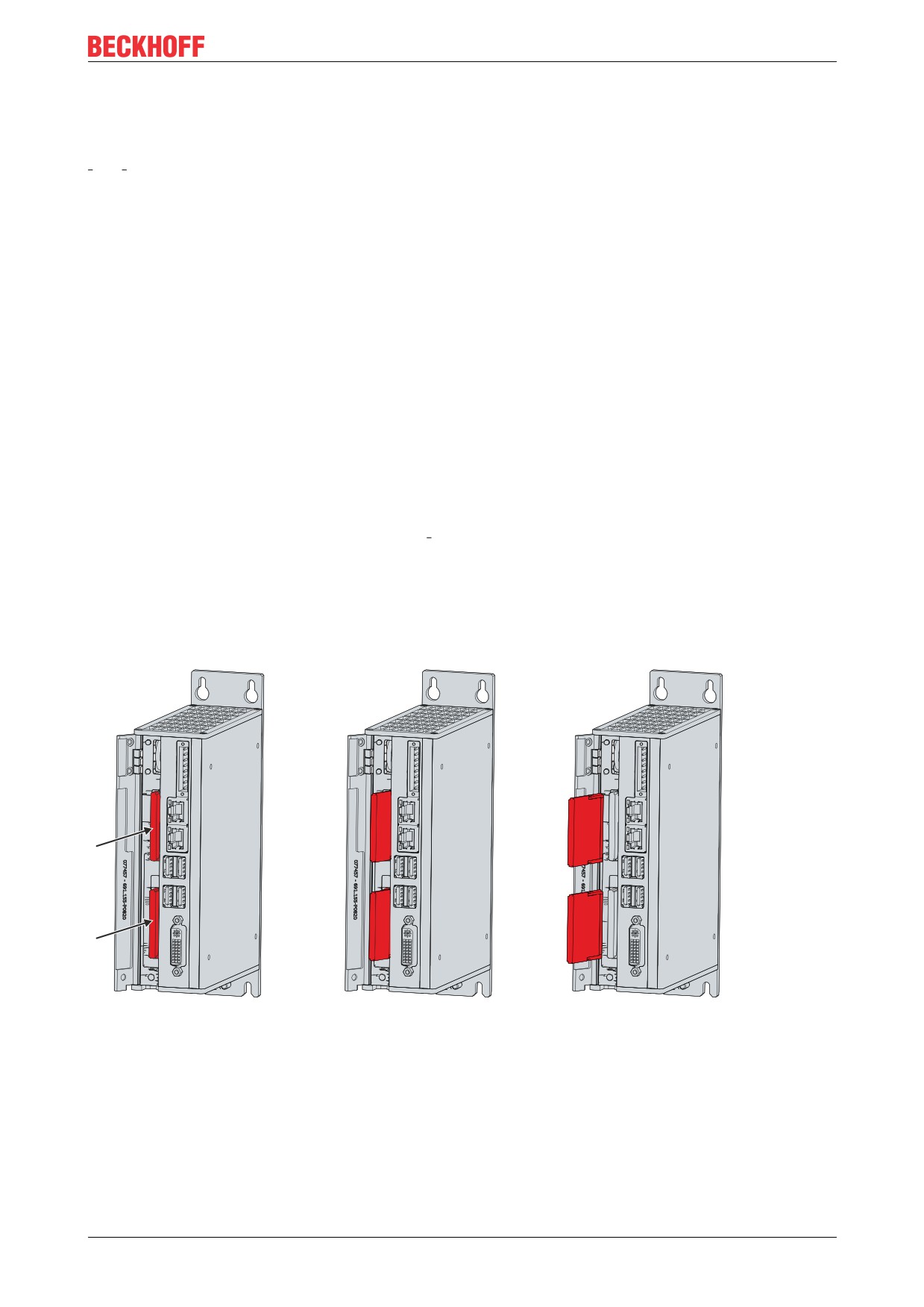
To change the CFast, follow the steps below, which are shown in fig. 20:
1. Press frontally against the CFast (section A).
The CFast now protrudes from the PC (section B).
2. Pull the CFast out of the PC (section C).
A
B
C
Fig. 20: C6915_Cfast replacement
3. Insert the new CFast into the PC.
4. Press frontally against the protruding CFast.
The CFast is now fully inserted in the PC. You have replaced the CFast.
Version: 2.5
37
Troubleshooting
8
Troubleshooting
Table 13: Troubleshooting
Fault
Cause
Measures
Nothing happens after the
Missing power supply of the
Check the power supply cable
Industrial PC has been switched on
Industrial PC
Call Beckhoff Service
Other cause
The Industrial PC does not boot
Setup settings are incorrect
Check the setup settings
fully
Other cause
Call Beckhoff Service
Computer boots, software starts,
Cause of the fault is either in the
Call the machine and software
but control does not operate
software or in parts of the plant
manufacturer
correctly
outside the Industrial PC
38
Version: 2.5

Technical data
9
Technical data
Table 14: Technical data
Product designation
Dimensions (W x H x D)
48 x 164 x 119 mm, without mounting plate
Weight
1250 g with basic equipment
Supply voltage
20.4-28.8 VDC (24 VDC power supply unit, NEC class
2)
Maximum power consumption with basic equipment1)
max. 14 W with basic configuration
Protection class
IP20
Vibration resistance (sinusoidal vibration)
EN 60068-2-6: 10 to 58 Hz: 0.035 mm
58 to 500 Hz: 0.5 G (approx. 5 m/s2)
Shock resistance (shock)
EN 60068-2-27: 5 G (approx. 50 m/s2), duration:
30 ms
EMC interference immunity
conforms to EN 61000-6-2
EMC interference emission
conforms to EN 61000-6-4
Permissible ambient temperature
+0 °C to 55 °C (operation)
-25 °C to +65 °C (transport / storage)
Permissible air humidity
Maximum 95 %, no condensation
Transport and storage
The same values for air humidity and shock
resistance are to be observed during transport and
storage as in operation. The shock resistance during
transport can be improved by means of suitably
packing the Industrial PC.
1)The power consumption of your device beyond the basic equipment can be found in the data sheet. There
you will find information on how the power consumption of your device changes according to the selected
equipment, accessories and connected devices.
Version: 2.5
39
Appendix
10
Appendix
10.1
Service and support
Beckhoff and its worldwide branch offices offer comprehensive service and support, providing fast and
competent assistance with all issues relating to Beckhoff products and system solutions.
Beckhoff Service
The Beckhoff Service Centre supports you in all matters of after-sales service:
• on-site service
• repair service
• spare parts service
• hotline service
Hotline: + 49 (0) 5246/963-460
Fax: + 49 (0) 5246/963-479
e-mail: service@beckhoff.com
If servicing is required, please quote the serial number of your Industrial PC, which can be found on the
name plate.
Beckhoff Support
Support offers you comprehensive technical assistance, helping you not only with the application of
individual Beckhoff products, but also with other, wide-ranging services:
• World-wide support
• design, programming and commissioning of complex automation systems
• extensive training program for Beckhoff system components
Hotline: + 49 (0) 5246/963-157
Fax: + 49 (0) 5246/963-9157
e-mail: support@beckhoff.com
Headquarters
Beckhoff Automation GmbH & Co. KG
Hülshorstweg 20
33415 Verl
Germany
Phone: + 49 (0) 5246/963-0
Fax: + 49 (0) 5246/963-198
e-mail: info@beckhoff.de
The addresses of the worldwide Beckhoff branch offices and agencies can be found on our website at http://
www.beckhoff.com/.
You will also find further documentation for Beckhoff components there.
40
Version: 2.5
Appendix
10.2
Approvals
The following table shows the approvals of the Industrial PC based on the device generation:
Table 15: C6915 approvals
Device generation
Approvals
C6915-0010
CE, EAC, UKCA, FCC
C6915-0020
CE, EAC, UKCA, FCC
You will find all other applicable approvals on the name plate of your device.
FCC approvals for the United States of America
FCC: Federal Communications Commission Radio Frequency Interference Statement
This device was tested and complies with the limits for a digital device of class A, according part 15 of the
FCC regulations. These limits are designed to provide adequate protection against adverse interference, if
the device is used in a commercial environment. This device generates, uses and may emit radio frequency
energy and may cause adverse interference with radio communications, if it is not installed and used in
accordance with the operating instructions. If this device is used in a residential area it is likely to cause
adverse interference, in which case the user must take appropriate countermeasures in order to eliminate
the interference at his own expense.
FCC approvals for Canada
FCC: Canadian Notice
This device does not exceed the class A limits for radiation, as specified by the Radio Interference
Regulations of the Canadian Department of Communications.
Version: 2.5
41
List of figures
List of figures
Fig.
1
C6915_structure
10
Fig.
2
C6915_Voltage socket pin numbering
11
Fig.
3
C6915_Ethernet interface pin numbering
12
Fig.
4
C6915_USB interface pin numbering
13
Fig.
5
C6915_DVI interface
14
Fig.
6
C6915 Status LEDs
15
Fig.
7
C6915_Name plate example
16
Fig.
8
C6915_Mounting plates
18
Fig.
9
C6915_Dimensions with mounting plate 1
19
Fig.
10
C6915_Dimensions with mounting plate 2
19
Fig.
11
C6915_Control cabinet installation
20
Fig.
12
C6915_Mounting the strain relief housing
22
Fig.
13
C6915_Wiring diagram
25
Fig.
14
Beckhoff Device Manager - Change passwords
28
Fig.
15
Beckhoff Device Manager - Start page
29
Fig.
16
C6915_Dismantling the control cabinet
31
Fig.
17
C6915_tool-less access to battery and storage media
35
Fig.
18
C6915 _Battery and storage media
35
Fig.
19
C6915_Battery change
36
Fig.
20
C6915_Cfast replacement
37
42
Version: 2.5
List of tables
List of tables
Table 1
Key: C6915 structure
10
Table 2
Voltage socket pin assignment
11
Table 3
Controller classification based on device generations
12
Table 4
Ethernet interface pin assignment
12
Table 5
USB interfaces based on device generation
13
Table 6
USB interface pin assignment
13
Table 7
DVI interface pin assignment
14
Table 8
Meaning of the Status LEDs
15
Table 9
Key: name plate C6915
16
Table 10 UPS communication
27
Table 11 Replacement recommendations for PC components
33
Table 12 Technical data of the battery
36
Table 13 Troubleshooting
38
Table 14 Technical data
39
Table 15 C6915 approvals
41
Version: 2.5
43