Kawasaki Robot Controller E Series. Installation and Connection Manual (2009)
Preface
This manual describes installation and connection procedures for Kawasaki Robot R Series.
Read and understand the contents of this and “Safety Manual” thoroughly and strictly observe all rules
for safety before proceeding with any operation. Kawasaki cannot take any responsibility for any
accidents and/or damages caused by operations that are based on only the limited part of this manual.
This manual describes only the installation and connection of the Robot Arm. Please refer to the
following manual for installation and connection of Controller and for Arc-welding Robots.
“Installation and Connection Manual” for controller
“Installation and Connection Manual” for arc welding
This manual is applicable to the following robot arms.
RA05L, RA06L, RA10L, RA10N, RA20N, RC05L, RD80N, RS05L, RS05N, RS06L,
RS07N, RS07L, RS10L, RS10N, RS15X, RS20N, RS30N, RS50N, RS80N
1. This manual does not constitute a guarantee of the systems in which the robot is utilized.
Accordingly, Kawasaki is not responsible for any accidents, damages, and/or problems relating to
industrial property rights as a result of using the system.
2. It is recommended that all personnel assigned for activation of operation, teaching, maintenance or
inspection of the robot attend the necessary education/training course(s) prepared by Kawasaki,
before assuming their responsibilities.
3. Kawasaki reserves the right to change, revise, or update this manual without prior notice.
4. This manual may not, in whole or in part, be reprinted or copied without the prior written consent of
Kawasaki.
5. Store this manual with care and keep it available for use at any time. If the robot is reinstalled or
moved to a different site or sold off to a different user, attach this manual to the robot without fail. In
the event the manual is lost or damaged severely, contact Kawasaki.
Symbols
The items that require special attention in this manual are designated with the following symbols.
Ensure proper and safe operation of the robot and prevent physical injury or property damages by
complying with the safety matters given in the boxes with these symbols.
㸟
DANGER
Failure to comply with indicated matters can result in
imminent injury or death.
㸟
WARNING
Failure to comply with indicated matters may possibly
lead to injury or death.
㸟
CAUTION
Failure to comply with indicated matters may lead to
physical injury and/or mechanical damage.
[NOTE]
Denotes precautions regarding robot specification,
handling, teaching, operation, and maintenance.
㸟
WARNING
1. The accuracy and effectiveness of the diagrams, procedures, and detail
explanations given in this manual cannot be confirmed with absolute certainty.
Accordingly, it is necessary to give one’s fullest attention when using this manual
to perform any work.
2. Safety related contents described in this manual apply to each individual work
and not to all robot work. In order to perform every work in safety, read and
fully understand the “Safety Manual”, all pertinent laws, regulations and related
materials as well as all the safety explanation described in each chapter, and
prepare safety measures suitable for actual work.
ii
Table of Contents
Preface
i
Symbols
ii
1
Precautions
1
1.1
Precautions during Transportation, Installation and Storage
1
1.2
Installing Environment of Robot Arm
2
1.3
Warning Label
3
2
Work Flow at Arm Installation and Connection
4
3
Motion Range and Specifications of Robot
5
3.1
Determination of Safety Fence Installation Location
5
3.2
Motion Range and Specifications of Robot
6
4
Robot Transportation Method
20
4.1
Using Wire Sling (Without Base Plate)
20
4.2
Using Wire Sling (With Base Plate)
21
5
Installation Dimensions of Base Section
22
6
Dimensions of Robot Pedestal
26
7
Installation Method
28
7.1
When Installing the Robot Directly on the Floor
28
7.2
When Installing the Robot Pedestal on the Floor
29
7.3
When Installing the Robot Base Plate on the Floor (Without Pedestal)
30
7.4
When Installing the Robot Base Plate on the Floor
31
8
Mounting of Tools
32
8.1
Dimensions of Wrist End
32
8.2
Specification of Mounting Bolt
33
8.3
Load Capacity
34
9
Mounting External Equipment
39
9.1
Service Tapped Hole Positions
39
9.2
Calculation of Load Caused by External Equipment
46
10
Connection of Air System
48
10.1
Air Piping Arrangement
48
10.2
Air Supply to the Robot Arm
53
10.3
Tubing from Air Outlet to Tool
55
iii
1
Precautions
1.1 Precautions during Transportation, Installation and Storage
When transporting the Kawasaki Robot to its installation site, strictly observe the following cautions.
㸟
WARNING
1. When the robot arm is to be transported by using a crane or forklift, never support the
robot arm manually.
2. During transportation, never climb on the robot arm or stay under the hoisted robot
arm.
3. Prior to installation, turn OFF the controller power switch and the external power switch
for shutting down power supply to the controller. Display signs indicating clearly
“Installation and connection in progress”, and lockout/tagout the external power switch
to prevent accidents of electric shock etc. caused when someone accidentally turns ON the
power.
4. Prior to moving robot, ensure safety by first confirming no abnormality is observed in
installing condition, etc., and then turn ON motor power to set robot to the desired pose.
Be careful not to be caught by/between any moving parts due to careless approach to
robot and peripheral equipment. After setting robot to the specified pose, turn OFF the
controller power and the external power switch again as mentioned above. Display signs
indicating clearly “Installation and connection in progress”, and lockout/tagout the
external power switch before starting installation and connection.
㸟
CAUTION
1. Since the robot arm is composed of precision parts, be careful not to apply excessive
shocks or vibrations during transportation.
2. Prior to installation, remove all obstacles so the installation is carried out smoothly and
safely. Clear a passage to the installation area for transportation of the robot arm using a
crane or forklift.
3. During transportation and storage,
(1) Keep the ambient temperature within the range of -10 to 60°C,
(2) Keep the relative humidity within the range of 35 to 85% RH without dew
condensation,
(3) Keep free from excessively strong vibration.
1
1.2 Installing Environment of Robot Arm
The robot arm must be installed in a place that satisfies all the following environmental conditions:
1.
When robot is installed on the floor, the levelness must be within 5.
2.
Be sure that the installation floor/pedestal has sufficient rigidity.
3.
Secure a flatness to prevent undue force applied to the installation section. (If sufficient flatness is
unobtainable, insert liners and adjust the flatness.)
4.
Keep the ambient temperature during operation within the range of 0 to 45C. (Deviation or
overload error may occur due to high viscosity of grease/oil when starting operation at low
temperatures. In this case, move the robot at low speed before regular operation.)
5.
Keep the relative humidity during operation within the range of 35 to 85%RH without dew
condensation.
6.
The robot installing place should be free from dust, dirt, oil, smoke, water, and other foreign
matters.
7.
The robot installing place should be free from flammable or corrosive liquid or gas.
8.
The robot installing place should be free from excessively strong vibration. (0.5 G or less)
9.
The robot installing place should be free from electric noise interference.
10.
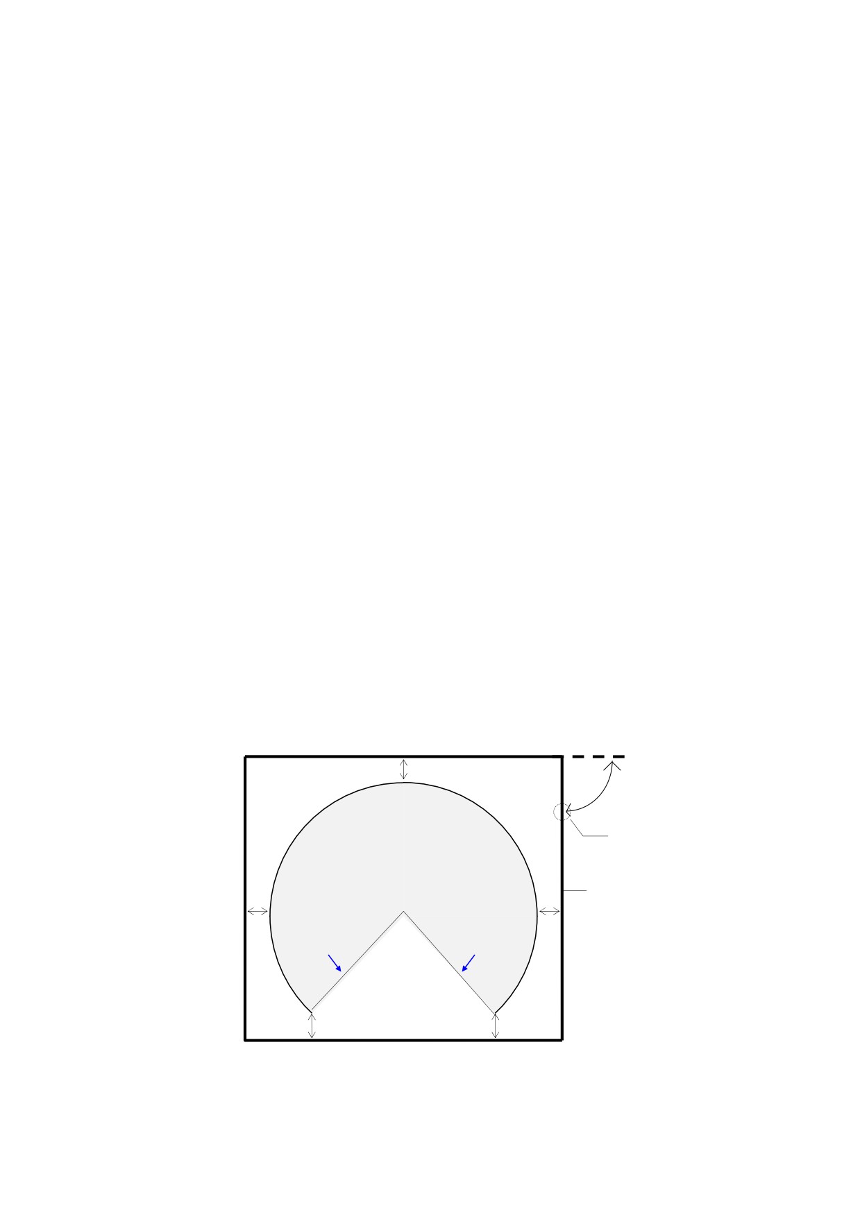
The robot installing place should be sufficiently larger than the motion range of robot arm.
(1) Install safety fence so the maximum movement of fully equipped robot arm (with tools and
workpieces) does not cause interference.
(2) Minimize the number of entrance gates (only one is best) and equip the entrance gate with a
safety plug.
(3) Observe the requirements of ISO 10218, etc. established in each region for details of the safety
fence.
Approx.1 m
A door
with Safety Plug
Scope of Robot Motion
(Tool and workpieces are included)
Safety Fence
Approx.1 m
Approx.1 m
Mechanical
Mechanical
stopper
stopper
Approx.1 m
Approx.1 m
2
R Series
1 Precautions
Kawasaki Robot Installation and Connection Manual
1.3 Warning Label
㸟
WARNING
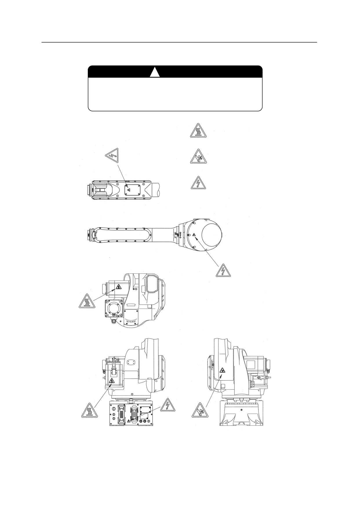
Pay attention to the warning labels listed in the drawings
below.
Warning label for high
temperature
Warning label for
pinching
Warning label for electric
shock
3
R Series
2 Work Flow at Arm Installation and Connection
Kawasaki Robot Installation and Connection Manual
2
Work Flow at Arm Installation and Connection
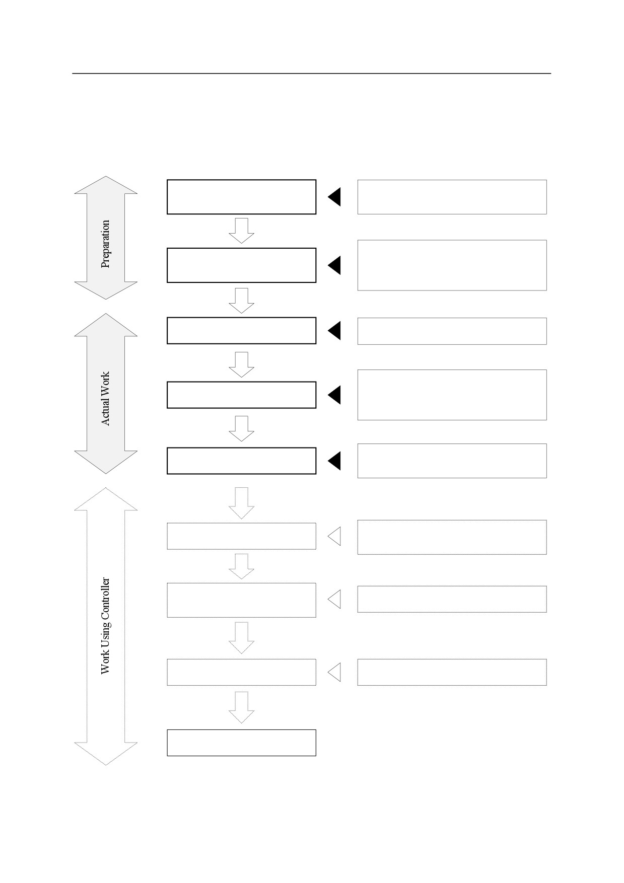
This workflow describes only the robot arm section. For the controller, refer to “Installation and
Connection Manual” for controller.
Examination of Installation Place
Refer to “3 Motion Range and
and Motion Range
Specifications of Robot”.
Refer to “5 Installation Dimensions of Base
Examination and Preparation of
Section”, “6 Dimensions of Robot
Installation Surface
Pedestal” and “7 Installation Method”.
Transportation of Robot Arm
Refer to “4 Robot Transportation Method”.
Refer to “5 Installation Dimensions of Base
Installation of Robot Arm
Section”, “6 Dimensions of Robot
Pedestal”, and “7 Installation Method”.
Refer to “8 Mounting of Tools” and “10
Mounting of Tools
Connection of Air System”.
Refer to “Installation and Connection
Connection to Controller
Manual” for controller.
Checking of Arm Motion
Refer to “Operation Manual”.
Checking of Tool Motion
Checking of Other Functions
Refer to “Operation Manual”.
Completion of Work
4
R Series
3 Motion Range and Specifications of Robot
Kawasaki Robot Installation and Connection Manual
3
Motion Range and Specifications of Robot
3.1 Determination of Safety Fence Installation Location
Point P
Motion Range of
Point P
Tool
Workpiece
A
L0
L1
L2
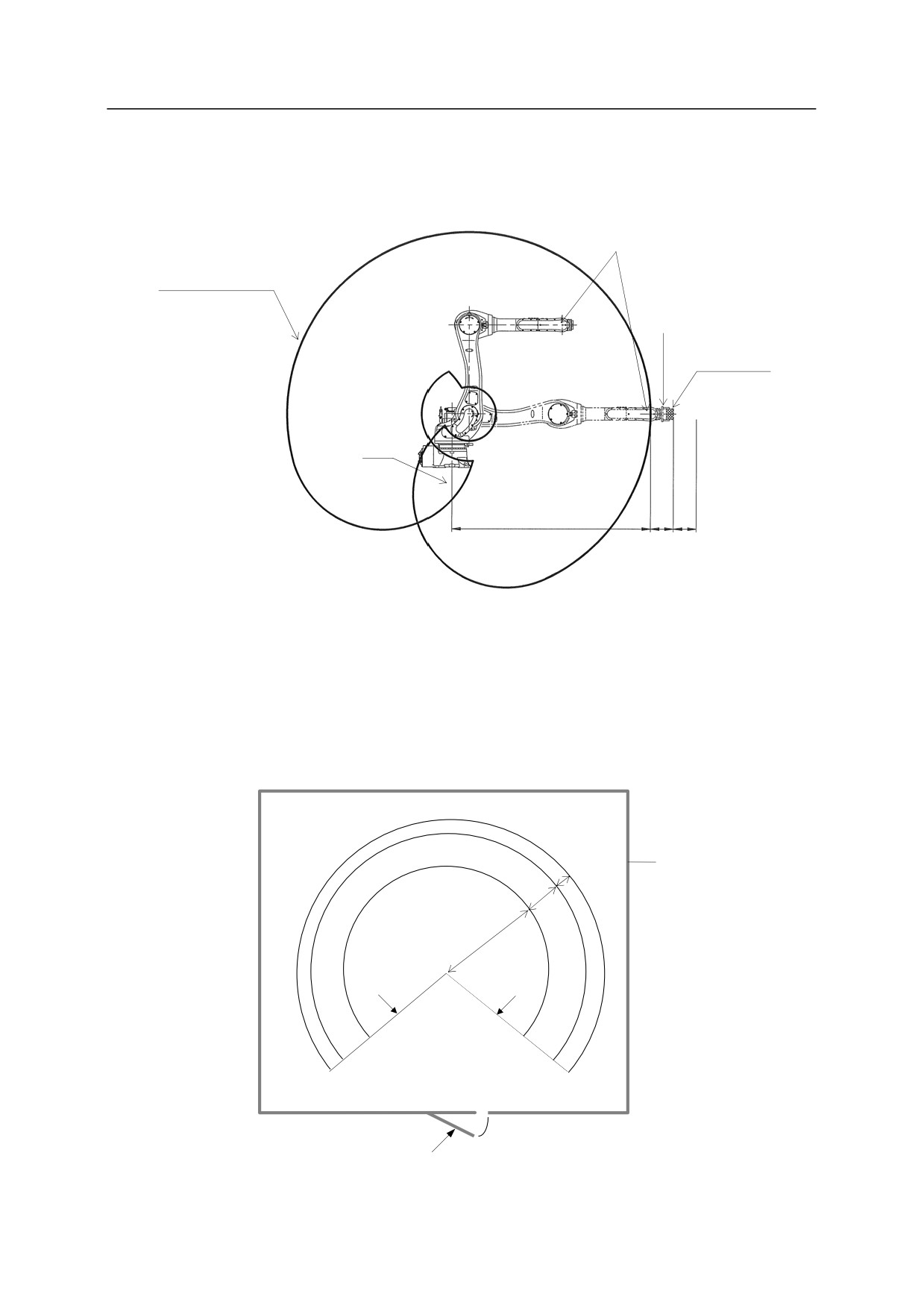
The motion range of the robot is represented by the maximum area that can be covered by point P in the
figure above. Therefore, as shown in the figure below, install the safety fence outside circle whose
radius is L0+L1+L2. Where; L0 is the length from the center line of arm (point A shown above) to the
farthest point of P, L1 is the length from point P to the farthest point of wrist flange, tool and workpiece,
and L2 is safety margin. For the length of L0, refer to the drawings in “3.2 Motion Range and
Specifications of Robot”.
Safety Fence
L2
L1
L0
Location of
Location of
Mechanical
Mechanical
Stopper
Stopper
Safety gate
5
R Series
3 Motion Range and Specifications of Robot
Kawasaki Robot Installation and Connection Manual
3.2 Motion Range and Specifications of Robot
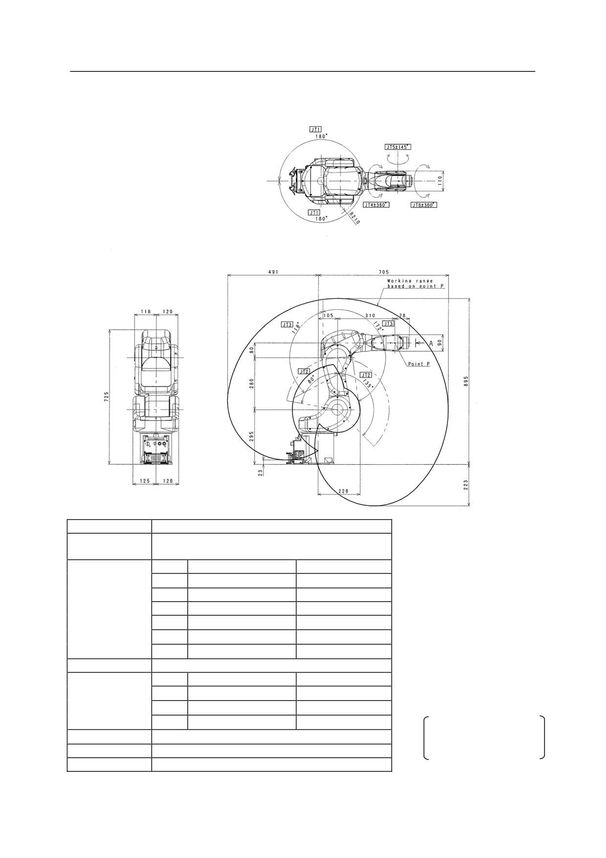
RS05N
Type
Articulated Robot
Degree of
6
Freedom
JT
Motion Range
Max. Speed
1
180°
360°/s
Motion Range
2
+135° to -80°
360°/s
and
3
+118° to -172°
410°/s
Maximum
4
360°
460°/s
Speed
5
145°
460°/s
6
360°
740°/s
*measured condition
Max. Payload
5 kg
࣭installed on the plate rigidly fixed
JT
Torque
Moment of Inertia
on the floor
Wrist Load
4
12.3 Nm
0.4 kgm2
࣭2000 mm away from JT1 center
Capacity
5
12.3 Nm
0.4 kgm2
6
7.0 Nm
0.12 kgm2
The noise level depends
Repeatability
0.02 mm
on the conditions.
Mass
34 kg
Acoustic noise
<80 dB (A)*
6
R Series
3 Motion Range and Specifications of Robot
Kawasaki Robot Installation and Connection Manual
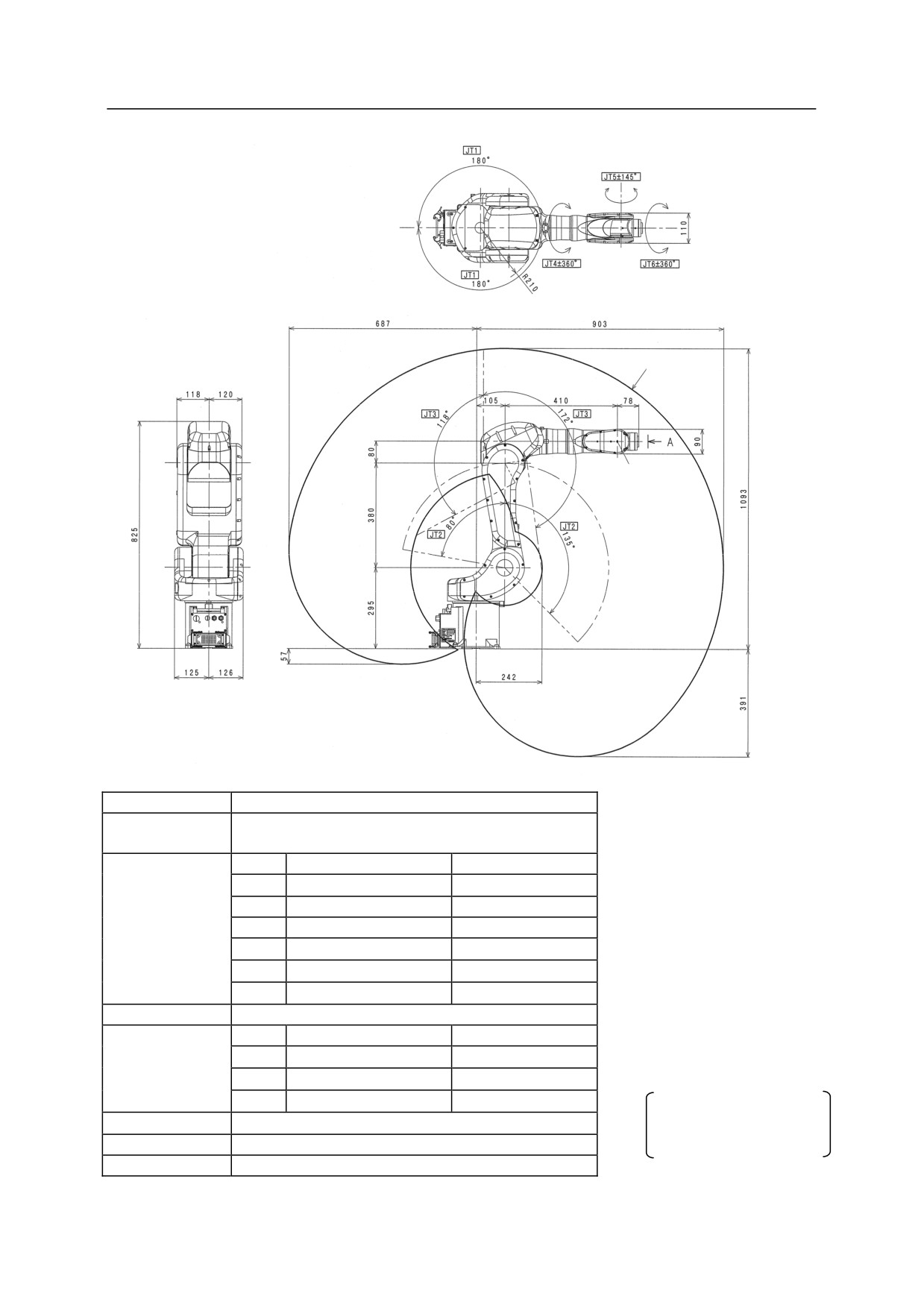
RS05L, RA05L
Motion range
of point P
Point P
Type
Articulated Robot
Degree of
6
Freedom
JT
Motion Range
Max. Speed
1
180°
300°/s
Motion Range
2
+135° to -80°
300°/s
and
3
+118° to -172°
300°/s
Maximum
4
360°
460°/s
Speed
5
145°
460°/s
6
360°
740°/s
*measured condition
Max. Payload
5 kg
࣭installed on the plate rigidly fixed
JT
Torque
Moment of Inertia
on the floor
Wrist Load
4
12.3 Nm
0.4 kgm2
࣭2200 mm away from JT1 center
Capacity
5
12.3 Nm
0.4 kgm2
6
7.0 Nm
0.12 kgm2
The noise level depends
Repeatability
0.03 mm
on the conditions.
Mass
37 kg
Acoustic noise
<80 dB (A)*
7
R Series
3 Motion Range and Specifications of Robot
Kawasaki Robot Installation and Connection Manual
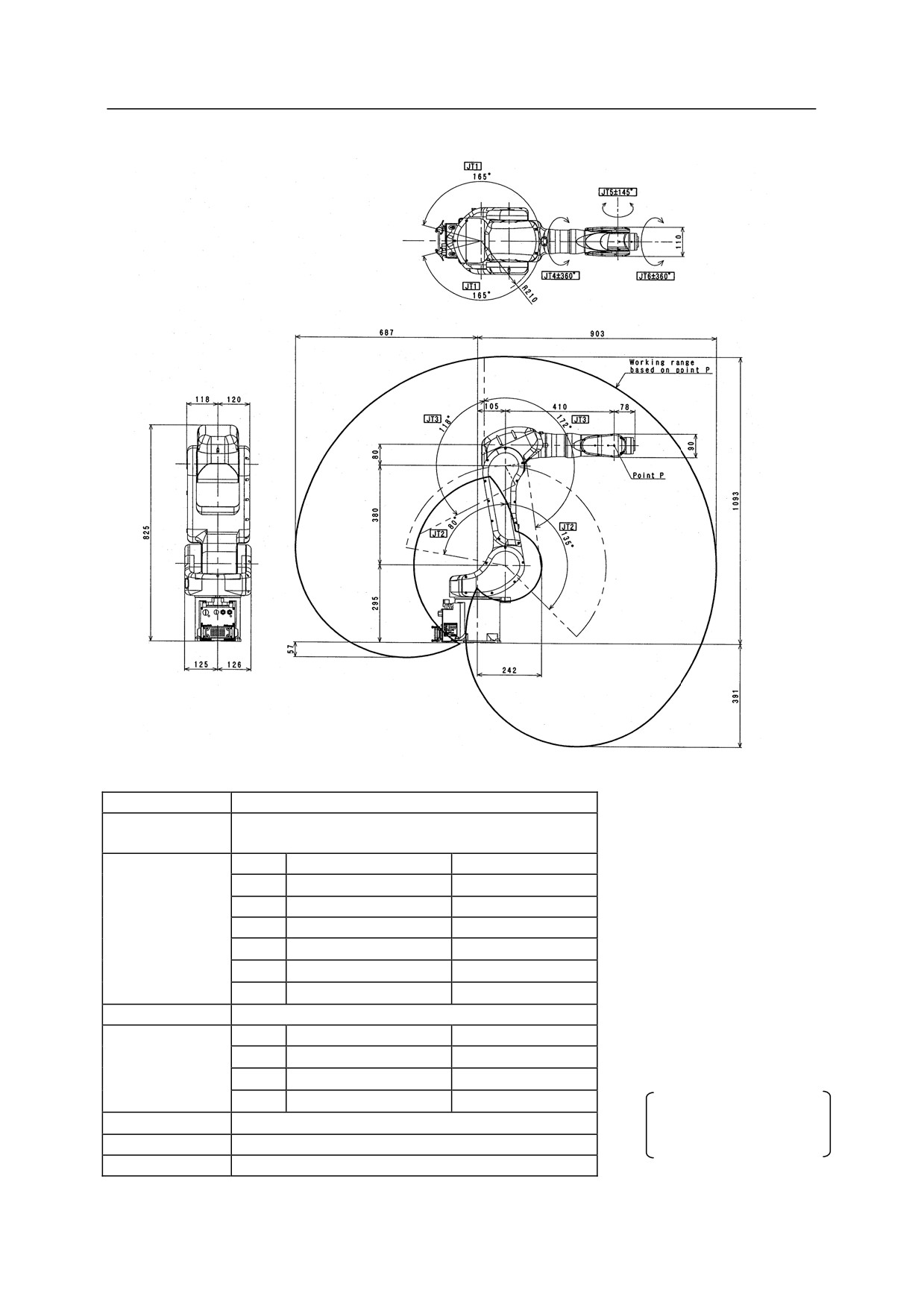
RC05L
Type
Articulated Robot
Degree of
6
Freedom
JT
Motion Range
Max. Speed
1
165°
300°/s
Motion Range
2
+135° to -80°
300°/s
and
3
+118° to -172°
300°/s
Maximum
4
360°
460°/s
Speed
5
145°
460°/s
6
360°
740°/s
*measured condition
Max. Payload
5 kg
࣭installed on the plate rigidly fixed
JT
Torque
Moment of Inertia
on the floor
Wrist Load
4
12.3 Nm
0.4 kgm2
࣭2200 mm away from JT1 center
Capacity
5
12.3 Nm
0.4 kgm2
6
7.0 Nm
0.12 kgm2
The noise level depends
Repeatability
0.03 mm
on the conditions.
Mass
37 kg
Acoustic noise
<80 dB (A)*
8
R Series
3 Motion Range and Specifications of Robot
Kawasaki Robot Installation and Connection Manual
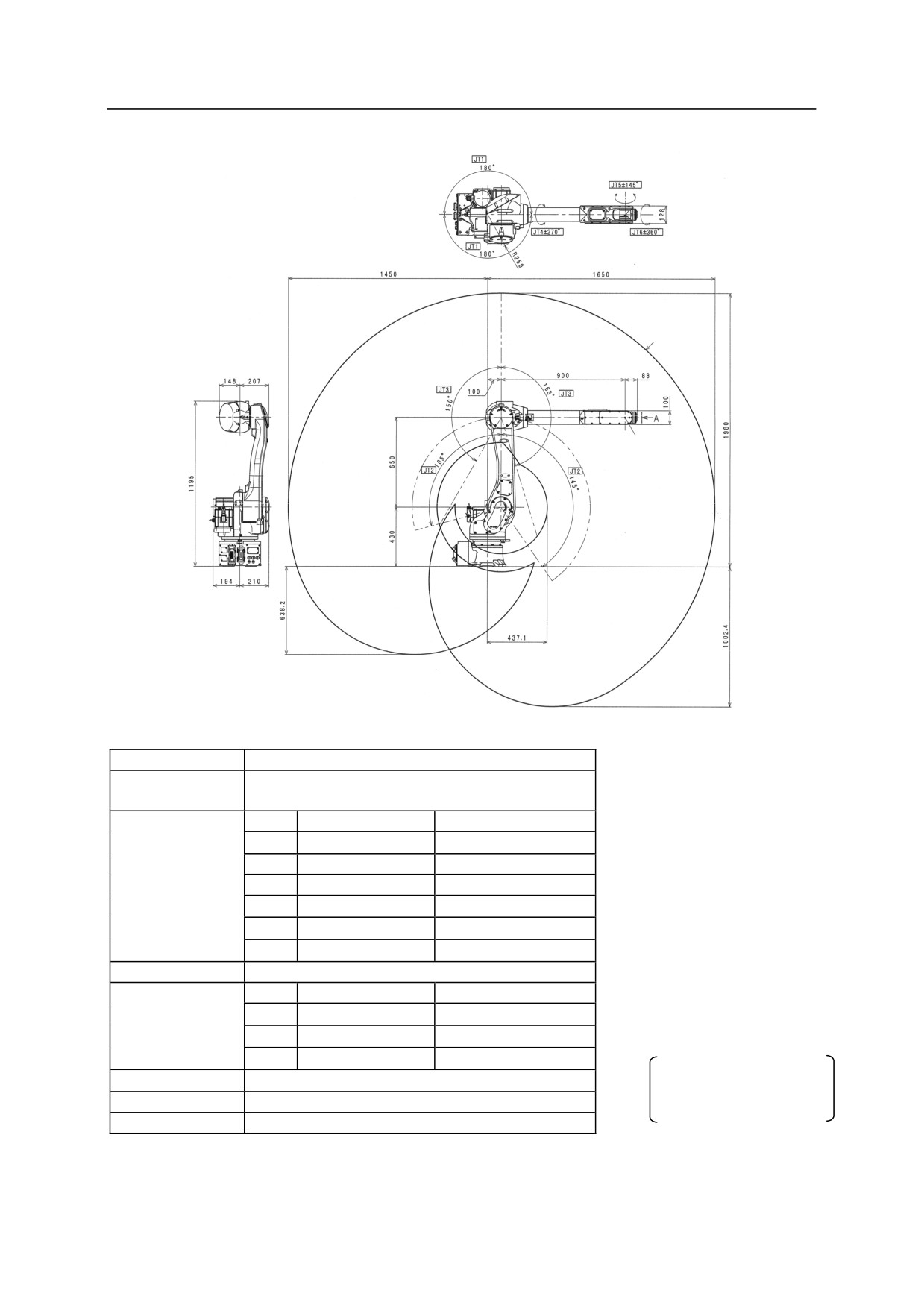
RS06L, RA06L
Motion range
of point P
Point P
Type
Articulated Robot
Degree of
6
Freedom
JT
Motion Range
Max. Speed
1
180°
250°/s
Motion Range and
2
+145° to -105°
250°/s
Maximum
3
+150° to -163°
215°/s
Speed
4
270°
365°/s
5
145°
380°/s
6
360°
700°/s
*measured condition
Max. Payload
6 kg
࣭installed on the plate rigidly fixed
JT
Torque
Moment of Inertia
on the floor
Wrist Load
4
13.0 Nm
0.45 kgm2
࣭2900 mm away from JT1 center
Capacity
5
13.0 Nm
0.45 kgm2
6
7.5 Nm
0.14 kgm2
The noise level depends
Repeatability
0.03 mm
on the conditions.
Mass
150 kg
Acoustic noise
<80 dB (A)*
9
R Series
3 Motion Range and Specifications of Robot
Kawasaki Robot Installation and Connection Manual
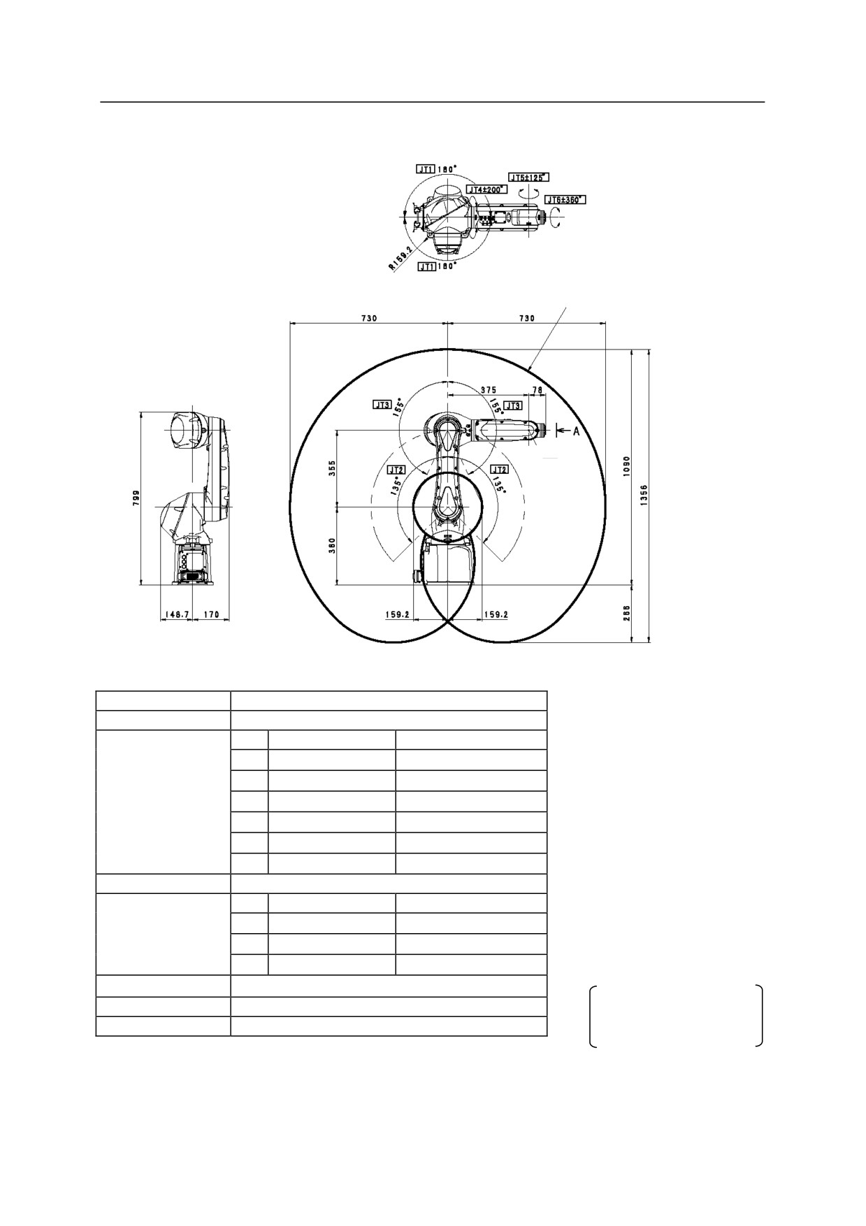
RS07N
Motion range
of point P
Point P
Type
Articulated Robot
Degree of Freedom
6
JT
Motion Range
Max. Speed
1
180
470/s
Motion Range and
2
135
380/s
Maximum
3
155
520/s
Speed
4
200
550/s
5
125
550/s
6
360
1000/s
Max. Payload
7 kg
*measured condition
JT
Torque
Moment of Inertia
࣭installed on the plate rigidly fixed
Wrist Load
4
17.0 Nm
0.5 kgm2
on the floor
Capacity
5
17.0 Nm
0.5 kgm2
࣭2000 mm away from JT1 center
6
10.0 Nm
0.2 kgm2
Repeatability
s0.02 mm
Mass
35 kg
The noise level depends
on the conditions.
Acoustic noise
<80 dB (A)*
10
R Series
3 Motion Range and Specifications of Robot
Kawasaki Robot Installation and Connection Manual
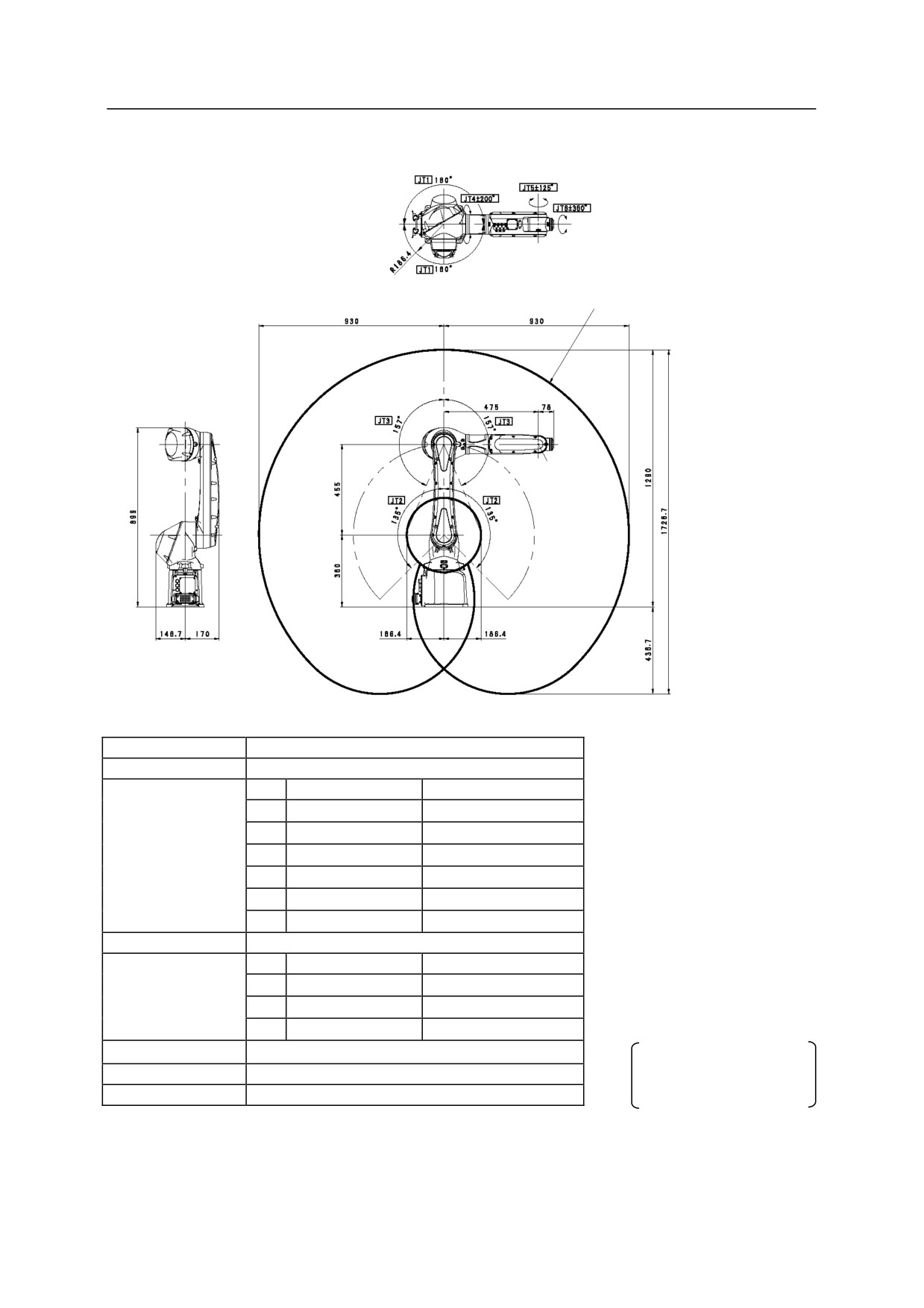
RS07L
Motion range
of point P
Point P
Type
Articulated Robot
Degree of Freedom
6
JT
Motion Range
Max. Speed
1
180
370/s
Motion Range and
2
135
310/s
Maximum
3
157
410/s
Speed
4
200
550/s
5
125
550/s
6
360
1000/s
Max. Payload
7 kg
*measured condition
JT
Torque
Moment of Inertia
࣭installed on the plate rigidly fixed
Wrist Load
4
17.0 Nm
0.5 kgm2
on the floor
Capacity
5
17.0 Nm
0.5 kgm2
࣭2200 mm away from JT1 center
6
10.0 Nm
0.2 kgm2
Repeatability
s0.03 mm
The noise level depends
Mass
36 kg
on the conditions.
Acoustic noise
<80 dB (A)*
11
R Series
3 Motion Range and Specifications of Robot
Kawasaki Robot Installation and Connection Manual
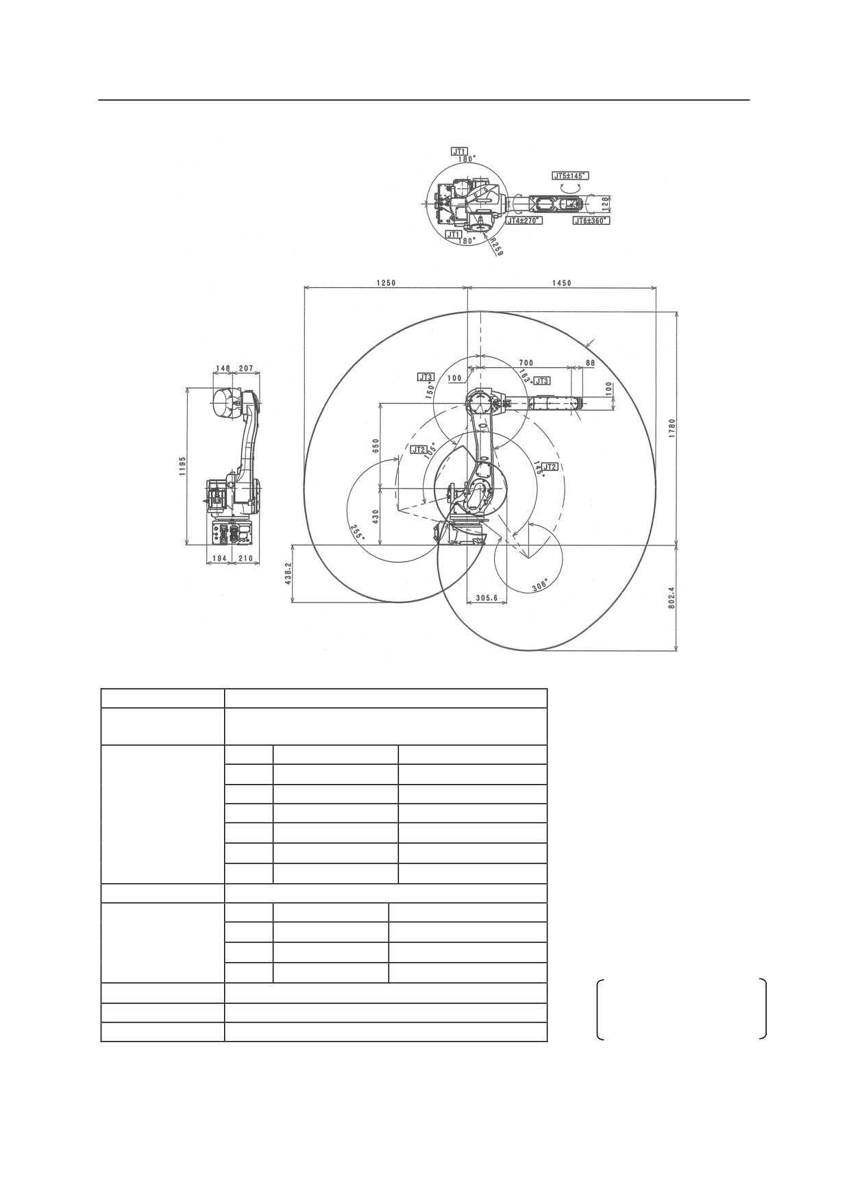
RS10N, RA10N
Motion range
of point P
Point P
Type
Articulated Robot
Degree of
6
Freedom
JT
Motion Range
Max. Speed
1
180°
250°/s
Motion Range and
2
+145° to -105°
250°/s
Maximum
3
+150° to -163°
215°/s
Speed
4
270°
365°/s
5
145°
380°/s
6
360°
700°/s
Max. Payload
10 kg
*measured condition
JT
Torque
Moment of Inertia
࣭installed on the plate rigidly fixed
Wrist Load
4
22.0 Nm
0.7 kgm2
on the floor
࣭2700 mm away from JT1 center
Capacity
5
22.0 Nm
0.7 kgm2
6
10.0 Nm
0.2 kgm2
Repeatability
0.03 mm
The noise level depends
Mass
150 kg
on the conditions.
Acoustic noise
<80 dB (A)*
12
R Series
3 Motion Range and Specifications of Robot
Kawasaki Robot Installation and Connection Manual
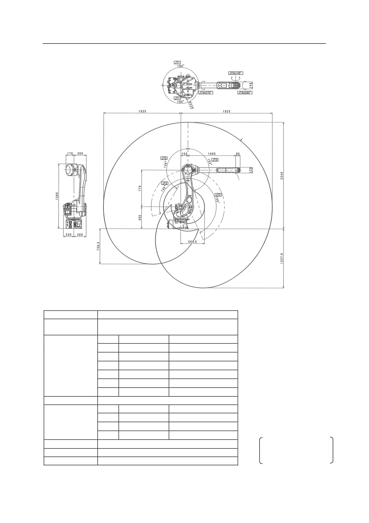
RS10L, RA10L
Motion range
of point P
Point P
Type
Articulated Robot
Degree of
6
Freedom
JT
Motion Range
Max. Speed
1
180
190s
Motion Range and
2
+155 to -105
205s
Maximum
3
+150 to -163
210s
Speed
4
270
400s
5
145
360s
6
360
610s
Max. Payload
10 kg
*measured condition
JT
Torque
Moment of Inertia
࣭installed on the plate rigidly fixed
on the floor
Wrist Load
4
22.0 Nm
0.7 kgm2
࣭3200 mm away from JT1 center
Capacity
5
22.0 Nm
0.7 kgm2
6
10.0 Nm
0.2 kgm2
Repeatability
0.05 mm
The noise level depends
Mass
230 kg
on the conditions.
Acoustic noise
<80 dB (A)*
13
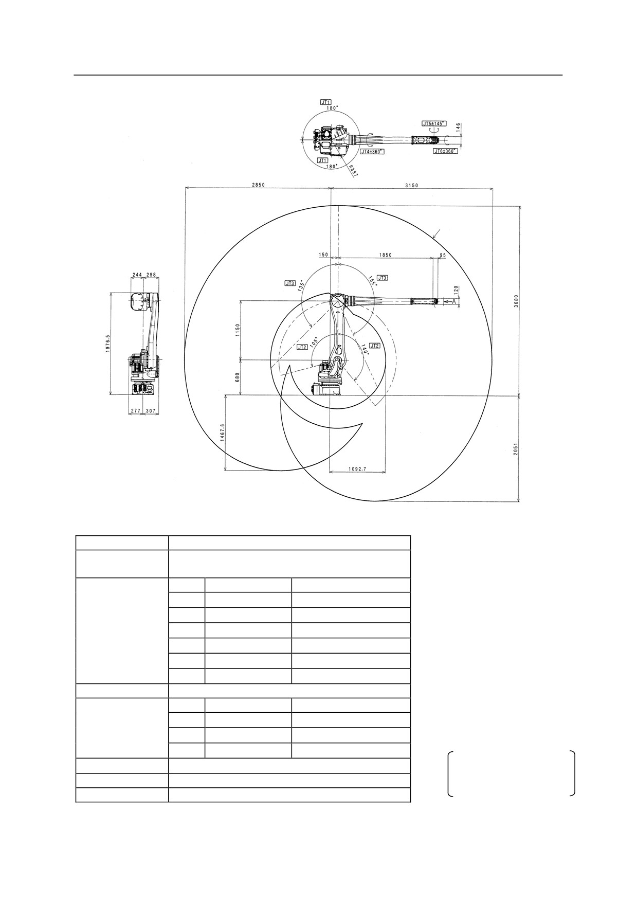
R Series
3 Motion Range and Specifications of Robot
Kawasaki Robot Installation and Connection Manual
RS15X
Motion range
of point P
Point P
Type
Articulated Robot
Degree of
6
Freedom
JT
Motion Range
Max. Speed
1
180
180s
Motion Range and
2
+140 to -105
180s
Maximum
3
+135 to -155
200s
Speed
4
360
410s
5
145
360s
6
360
610s
*measured condition
Max. Payload
15 kg
࣭installed on the plate rigidly fixed
JT
Torque
Moment of Inertia
on the floor
Wrist Load
4
34.0 Nm
0.8 kgm2
࣭4500 mm away from JT1 center
Capacity
5
34.0 Nm
0.8 kgm2
6
22.0 Nm
0.25 kgm2
Repeatability
0.06 mm
The noise level depends
on the conditions.
Mass
545 kg
Acoustic noise
<80 dB (A)*
14
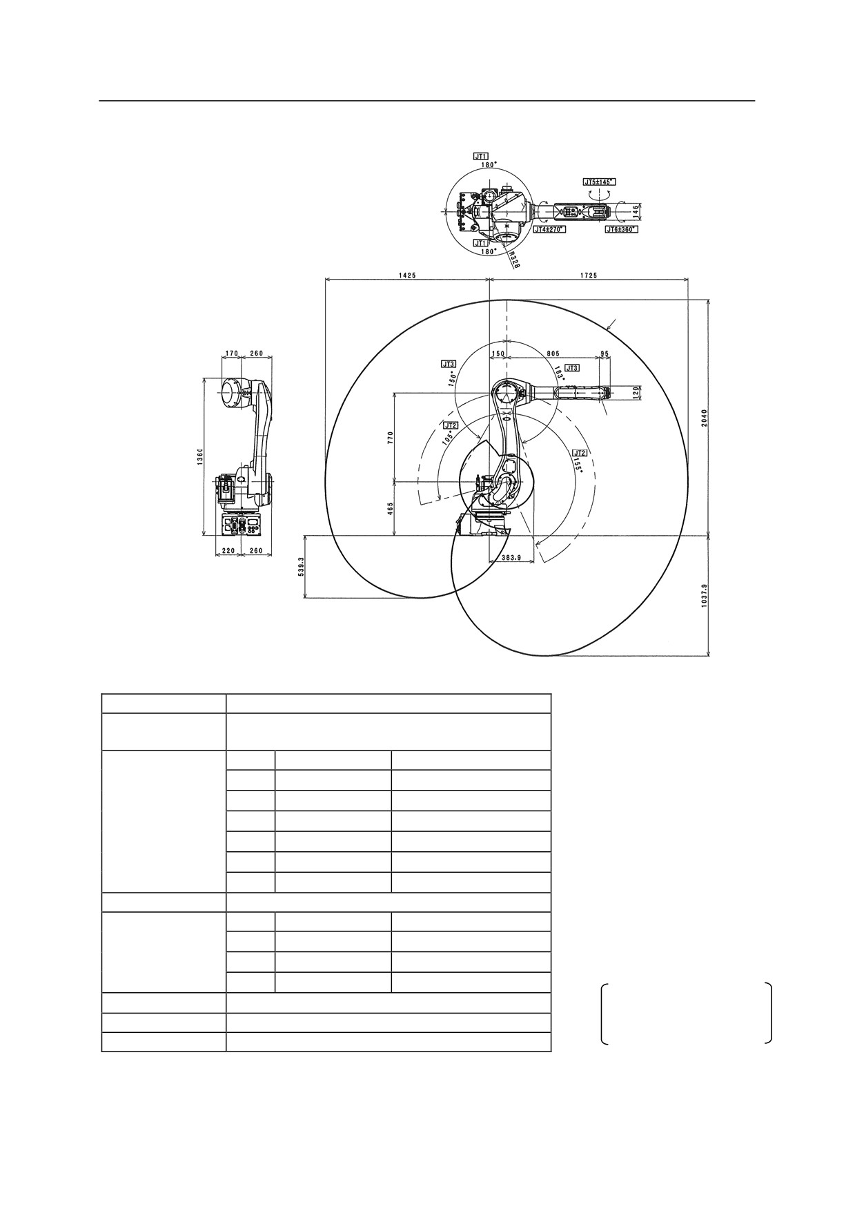
R Series
3 Motion Range and Specifications of Robot
Kawasaki Robot Installation and Connection Manual
RS20N, RA20N
Motion range
of point P
Point P
Type
Articulated Robot
Degree of
6
Freedom
JT
Motion Range
Max. Speed
1
180
190s
2
+155 to -105
205s
Motion Range and
Maximum
3
+150 to -163
210s
Speed
4
270
400s
5
145
360s
6
360
610s
*measured condition
Max. Payload
20 kg
࣭installed on the plate rigidly fixed
JT
Torque
Moment of Inertia
on the floor
Wrist Load
4
45.0 Nm
0.9 kgm2
࣭3000 mm away from JT1 center
Capacity
5
45.0 Nm
0.9 kgm2
6
29.0 Nm
0.3 kgm2
Repeatability
0.04 mm
The noise level depends
Mass
230 kg
on the conditions.
Acoustic noise
<80 dB (A)*
15
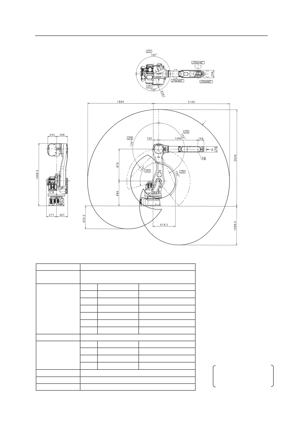
R Series
3 Motion Range and Specifications of Robot
Kawasaki Robot Installation and Connection Manual
RS30N
Motion range
of point P
Type
Articulated Robot
Degree of
6
Freedom
JT
Motion Range
Max. Speed
1
180
180s
2
+140 to -105
180s
Motion Range and
Maximum
3
+135 to -155
185s
Speed
4
360
260s
5
145
260s
6
360
360s
*measured condition
Max. Payload
30 kg
࣭installed on the plate rigidly fixed
JT
Torque
Moment of Inertia
on the floor
Wrist Load
4
210.0 Nm
16.8 kgm2
࣭4100 mm away from JT1 center
Capacity
5
210.0 Nm
16.8 kgm2
6
130.0 Nm
6.6 kgm2
The noise level depends
Repeatability
0.06 mm
on the conditions.
Mass
555 kg
Acoustic noise
<80 dB (A)*
16
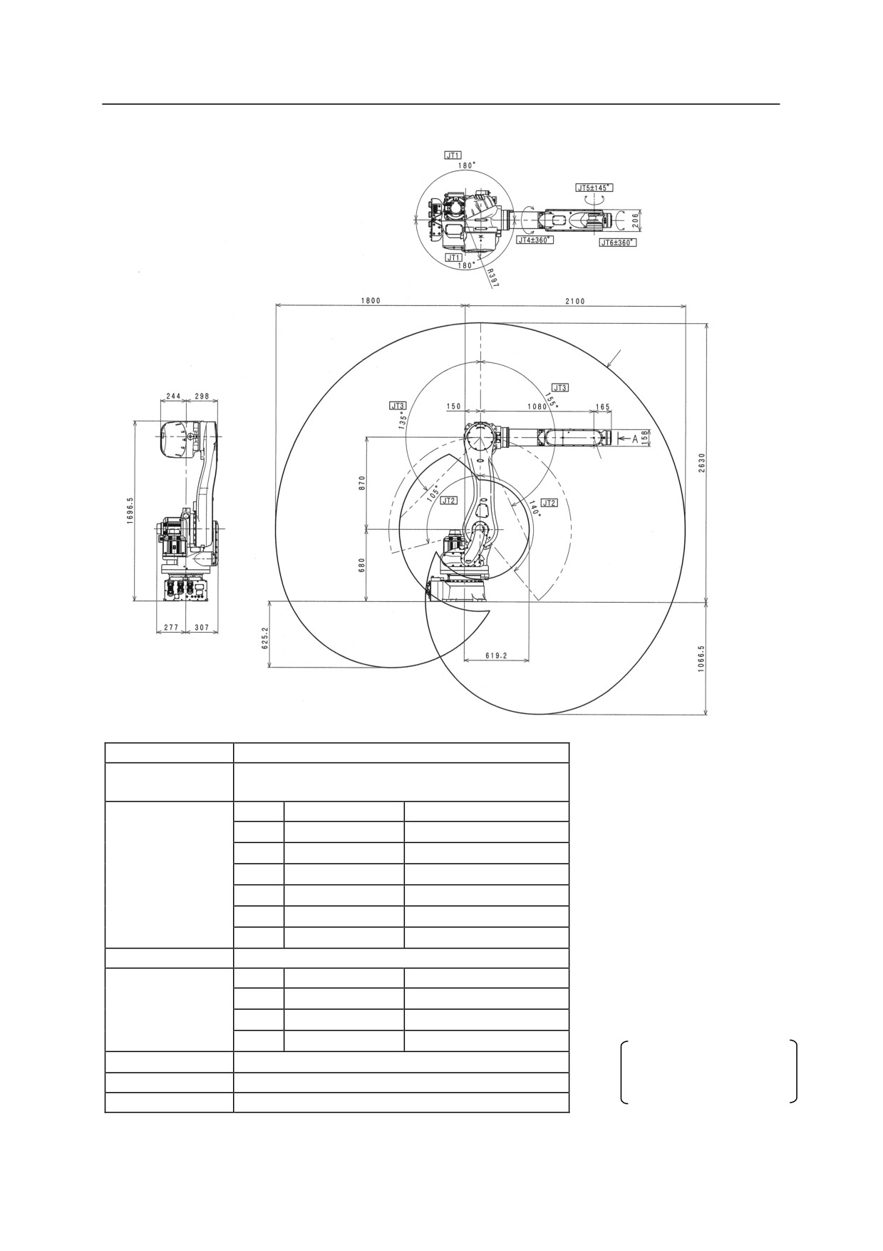
R Series
3 Motion Range and Specifications of Robot
Kawasaki Robot Installation and Connection Manual
RS50N
Motion range
of point P
Point P
Type
Articulated Robot
Degree of
6
Freedom
JT
Motion Range
Max. Speed
1
180
180s
Motion Range and
2
+140 to -105
180s
Maximum
3
+135 to -155
185s
Speed
4
360
260s
5
145
260s
6
360
360s
*measured condition
Max. Payload
50 kg
࣭installed on the plate rigidly fixed
JT
Torque
Moment of Inertia
on the floor
Wrist Load
4
210.0 Nm
28.0 kgm2
࣭4100 mm away from JT1 center
Capacity
5
210.0 Nm
28.0 kgm2
6
130.0 Nm
11.0 kgm2
Repeatability
0.06 mm
The noise level depends
on the conditions.
Mass
555 kg
Acoustic noise
<80 dB (A)*
17
R Series
3 Motion Range and Specifications of Robot
Kawasaki Robot Installation and Connection Manual
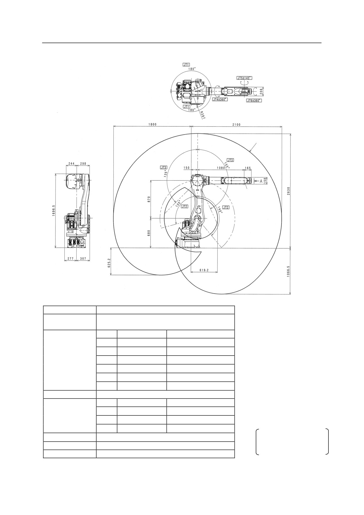
RS80N
Motion range
of point P
Point P
Type
Articulated Robot
Degree of
6
Freedom
JT
Motion Range
Max. Speed
1
180
180s
Motion Range and
2
+140 to -105
180s
Maximum
3
+135 to -155
160s
Speed
4
360
185s
5
145
165s
6
360
280s
*measured condition
Max. Payload
80 kg
࣭installed on the plate rigidly fixed
JT
Torque
Moment of Inertia
on the floor
Wrist Load
4
336.0 Nm
34.0 kgm2
࣭4100 mm away from JT1 center
Capacity
5
336.0 Nm
34.0 kgm2
6
194.0 Nm
13.7 kgm2
Repeatability
0.06 mm
The noise level depends
on the conditions.
Mass
555 kg
Acoustic noise
<80 dB (A)*
18
R Series
3 Motion Range and Specifications of Robot
Kawasaki Robot Installation and Connection Manual
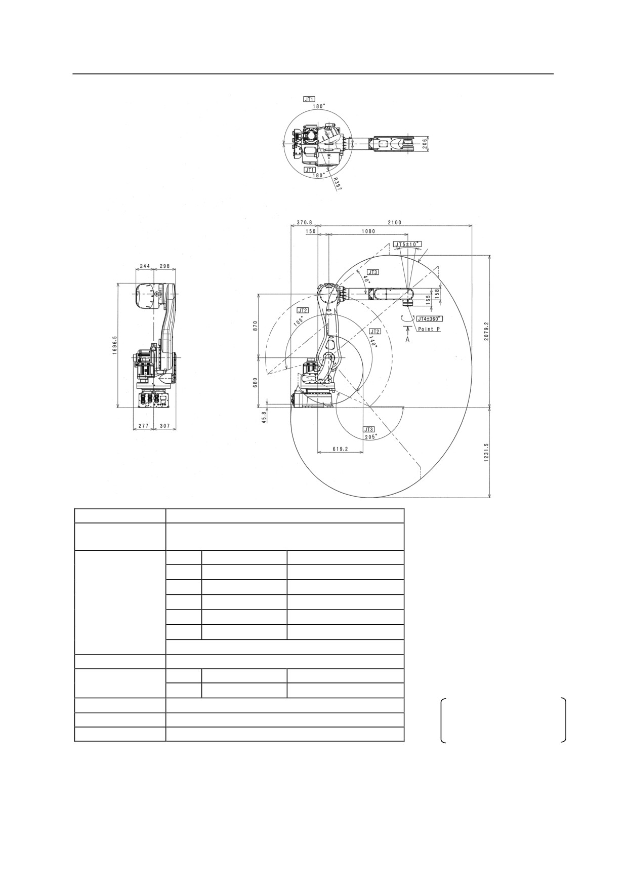
RD80N
Motion range
of point P
Type
Articulated Robot
Degree of
5
Freedom
JT
Motion Range
Max. Speed
1
180
180s
2
+140 to -105
180s
Motion Range and
Maximum
3
+40 to -205
175s
Speed
4
360
360s
5
10 **
-
*measured condition
**10 from vertical downward direction
࣭installed on the plate rigidly fixed
Max. Payload
80 kg
on the floor
Wrist Load
JT
Torque
Moment of Inertia
࣭4100 mm away from JT1 center
Capacity
4
-
13.7 kgm2
Repeatability
0.07 mm
The noise level depends
Mass
540 kg
on the conditions.
Acoustic noise
<80 dB (A)*
19
R Series
4 Robot Transportation Method
Kawasaki Robot Installation and Connection Manual
4
Robot Transportation Method
4.1 Using Wire Sling (Without Base Plate)
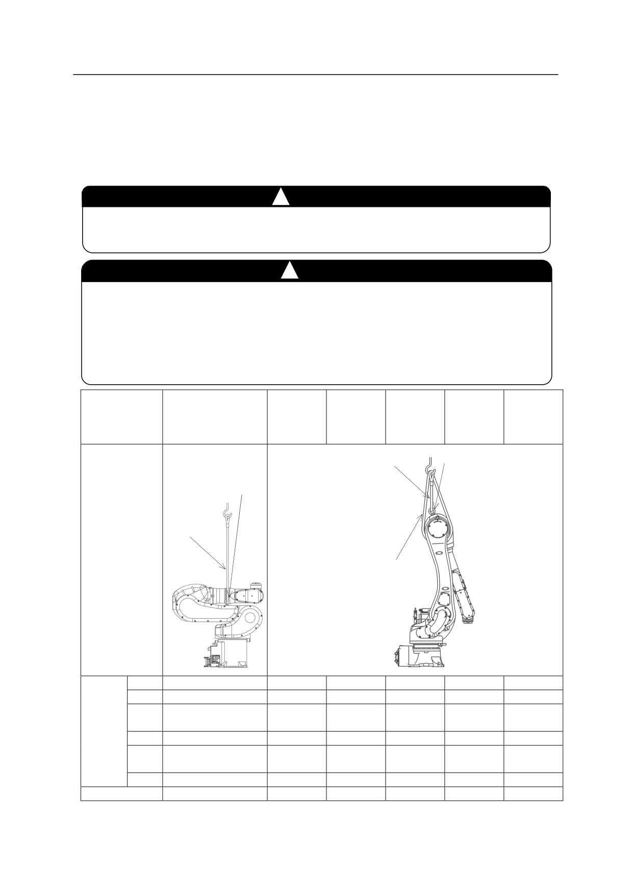
As shown in the figure below, hoist up the robot by fastening the wire slings to eyebolt attached to robot
arm. (Use the same method for hoisting up the robot with pedestal.)
㸟
WARNING
Add anti-rotation wire without fail when hoisting up robot. (Except RS05N, RS05L,
RA05L and RC05L.) If the robot rotates, eyebolt may come loose and the robot may fall.
㸟
CAUTION
When hoisting up the robot, be careful as robot may lean forward/backward depending on
robot posture and installation condition of the options. If the robot is hoisted up in an
inclined posture, it may swing, damage or the wire may interfere with the harness, piping
etc., or it may damage due to interfering with surrounding objects. Remove the eyebolt
attached to the arm once the transportation of robot is complete.
RS06L
RS10L
RS30N
RS05N, RS05L,
RS10N
RS07N
RS20N
RS50N
Model
RS15X
RA05L, RC05L
RA06L
RS07L
RA10L
RS80N
RA10N
RA20N
RD80N
1 Eyebolt
1 Wire
2 Eyebolts
2 Wires
Hoisted
up
1 Anti-rotation wire
posture
JT1
0°
0°
0°
0°
0°
0°
JT2
-80°
0°
10°
-3°
0°
1°
-158°
-155°
Hoisted
JT3
-170°
-163°
-163°
-155°
[-160°]
(-55°)
up
JT4
0°
0°
0°
0°
0°
0°
posture
-22°
JT5
90°
-17°
-20°
-25° (0°)
-114°
[-20°]
JT6
0°
0°
0°
0°
0°
0°
Eyebolt for arm
M8×2
M16×1
M6×1
M16×1
M24×1
M24×1
[
]: RS07L
(
): RD80N
20
R Series
4 Robot Transportation Method
Kawasaki Robot Installation and Connection Manual
4.2 Using Wire Sling (With Base Plate)
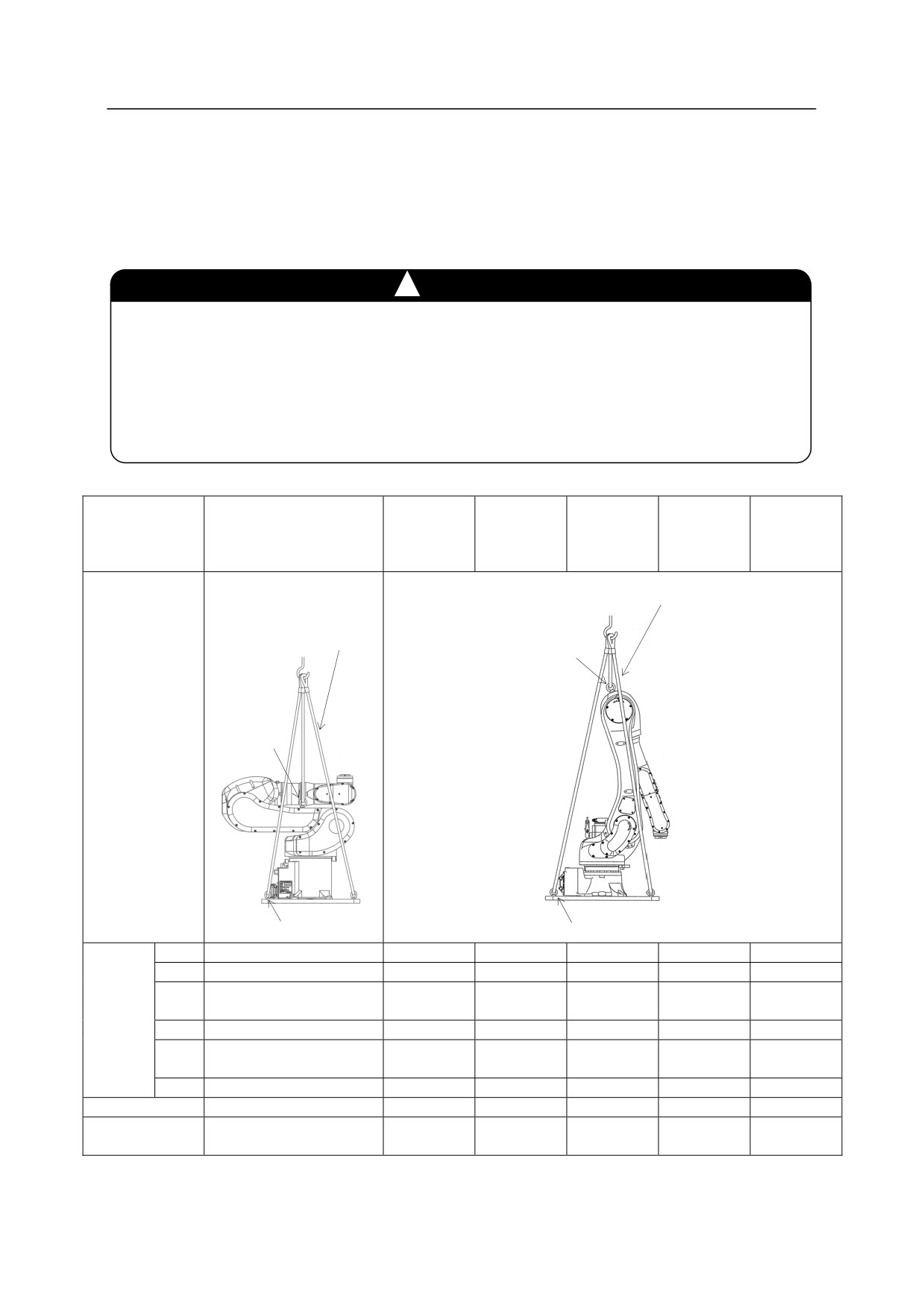
According to the figure below, hoist up the robot by fastening four wire slings to four eyebolts on the
base plate. In addition, fasten wire slings to the eyebolt on the arm to prevent the robot from accidentally
falling. (Use the same method for hoisting up the robot with pedestal.)
㸟
CAUTION
When hoisting up the robot, be careful as robot may lean forward/backward depending on
robot posture and installation condition of the options. If the robot is hoisted up in an inclined
posture, it may swing, damage or the wire may interfere with the harness, piping etc., or it
may damage due to interfering with surrounding objects. Protect the robot with wear plates,
etc. if wires interfere with a part of the robot. Remove the eyebolt attached to the arm.
RS06L
RS10L
RS30N
RS05N, RS05L,
RS10N
RS07N
RS20N
RS50N
Model
RS15X
RA05L, RC05L
RA06L
RS07L
RA10L
RS80N
RA10N
RA20N
RD80N
5 Wires
6 Wires
1 Eyebolt
Hoisted
2 Eyebolts
up
posture
4 Eyebolts
4 Eyebolts
JT1
0°
0°
0°
0°
0°
0°
JT2
-80°
0°
0°
-3°
0°
1°
-158°
Hoisted
JT3
-170°
-163°
-163°
-155°(-55°)
-155°
[-160°]
up
JT4
0°
0°
0°
0°
0°
0°
posture
-22°
JT5
90°
-17°
-20°
-25° (0°)
-114°
[-20°]
JT6
0°
0°
0°
0°
0°
0°
Eyebolts for arm
M8×2
M16×1
M6×1
M16×1
M24×1
M24×1
Part number of
60360-0081
60360-1201
60360-2102
60360-1203
60360-0086
60360-0086
base plate
[
]: RS07L
(
): RD80N
21
R Series
5 Installation Dimensions of Base Section
Kawasaki Robot Installation and Connection Manual
5
Installation Dimensions of Base Section
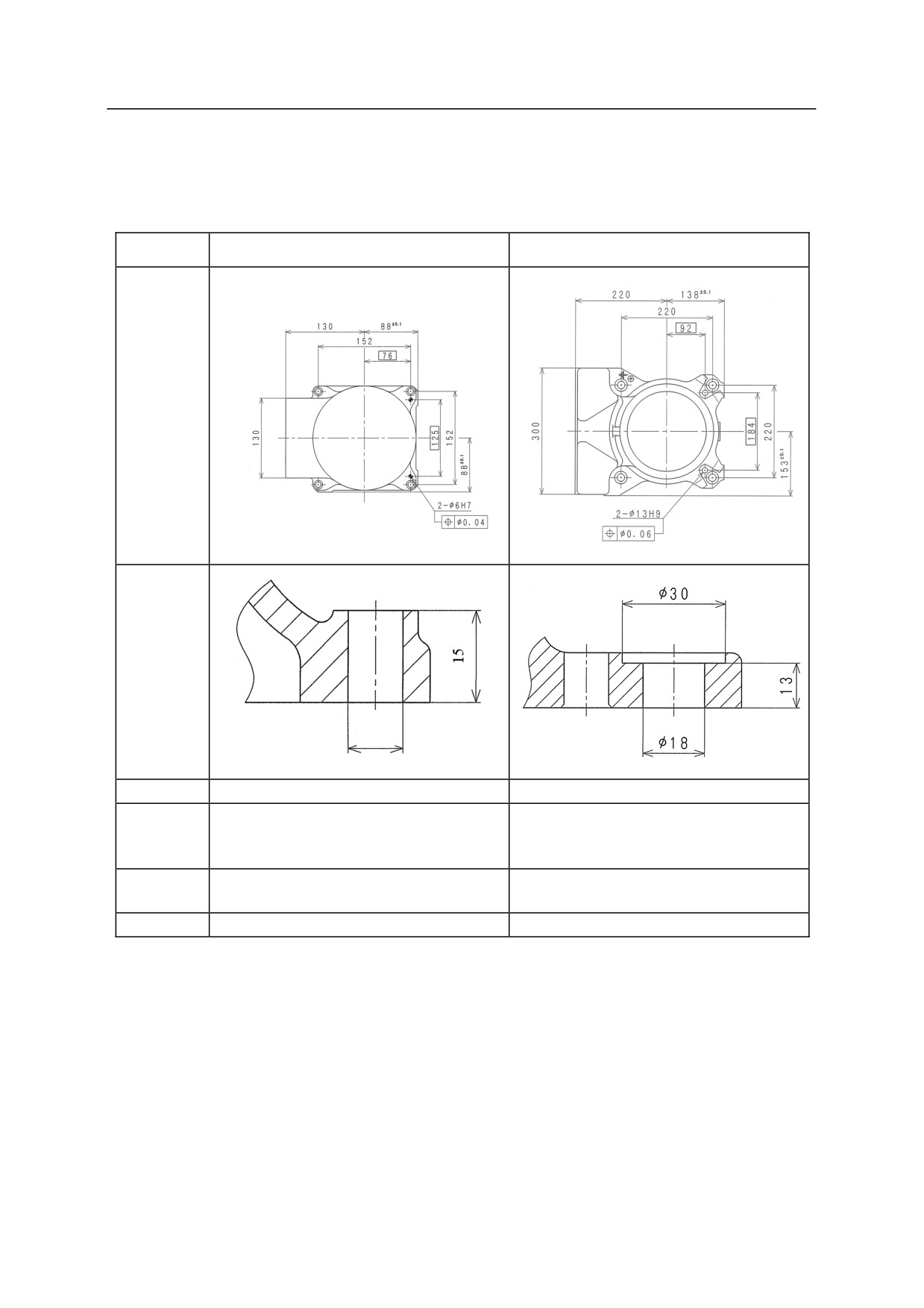
When installing a robot, fix the base section with high tension bolts through the bolt holes.
Model
RS05N, RS05L, RA05L, RC05L
RS06L, RS10N, RA06L, RA10N
Dimensions
for
installation
Cross-
section
of installation
section
9
Bolt hole
4-9
4-18
4-M8
4-M16
High tension
Material: SCM435
Material: SCM435
bolt
Strength class: 10.9 min.
Strength class: 10.9 min.
Tightening
29.4 Nm
235 Nm
torque
Levelness
Within 5°
Within 5°
22
R Series
5 Installation Dimensions of Base Section
Kawasaki Robot Installation and Connection Manual
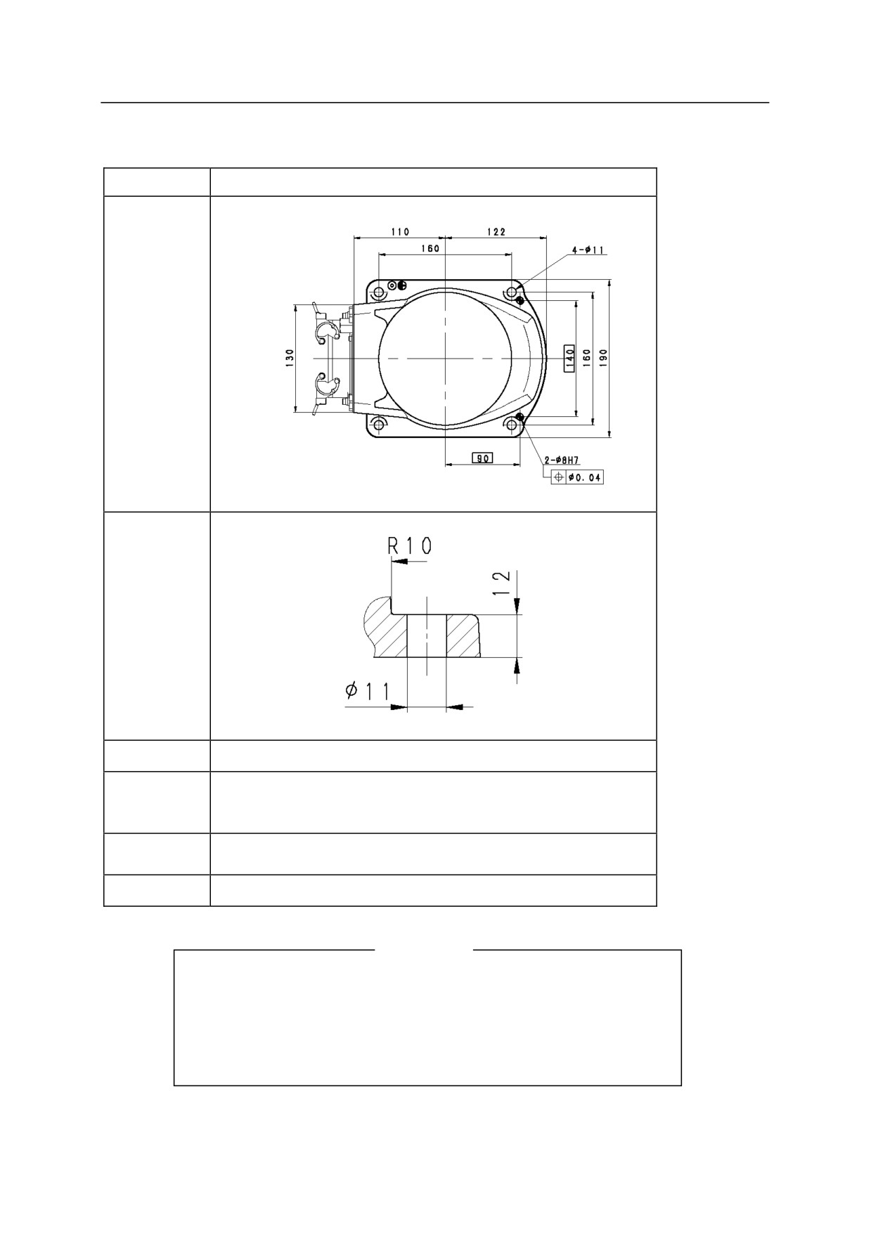
When installing a robot, fix the base section with high tension bolts through the bolt holes.
Model
RS07N, RS07L
Dimensions
for
installation
Cross-
section
of installation
section
Bolt hole
4-11
4-M10
High tension
Material: SCM435
bolt
Strength class: 10.9 min.
Tightening
56.8 Nm
torque
Levelness
Within 5°
[NOTE]
The robot may be removed for maintaining RS07N and RS07L.
Be sure to drill precise pin holes in the locations on the
installation surface as shown above so that you can use pins when
installing the robot.
23
R Series
5 Installation Dimensions of Base Section
Kawasaki Robot Installation and Connection Manual
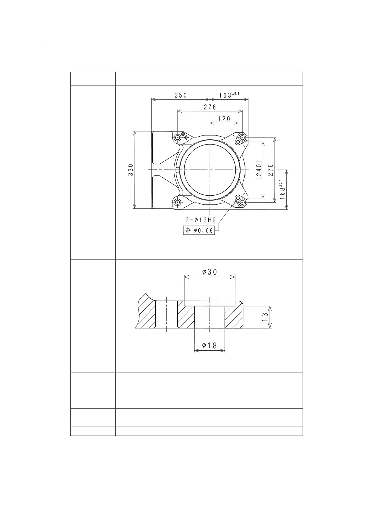
When installing a robot, fix the base section with high tension bolts through the bolt holes.
Model
RS10L, RS20N, RA10L, RA20N
Dimensions
for
installation
Cross-section
of installation
section
Bolt hole
4-18
4-M16
High tension
Material: SCM435
bolt
Strength class: 10.9 min.
Tightening
235 Nm
torque
Levelness
Within 5°
24
R Series
5 Installation Dimensions of Base Section
Kawasaki Robot Installation and Connection Manual
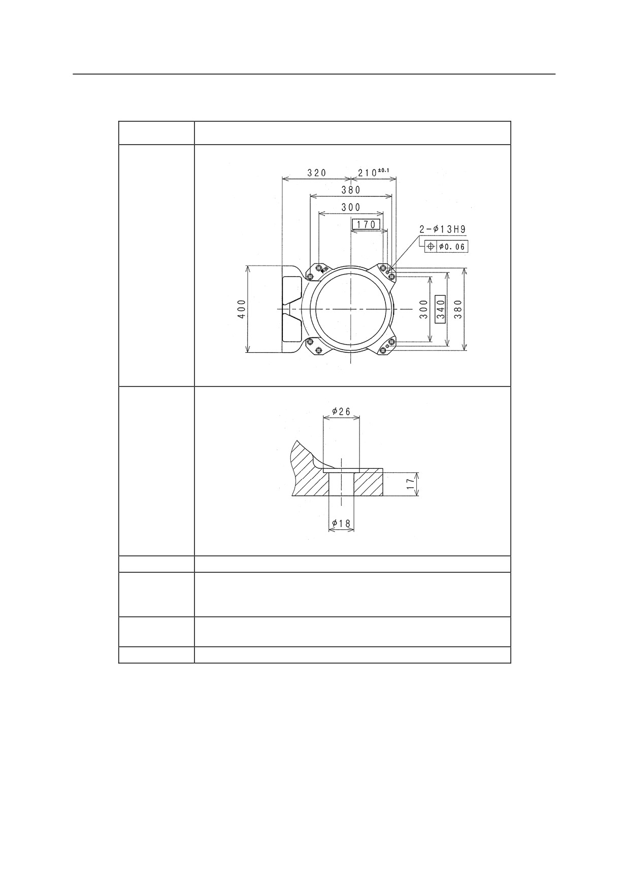
When installing a robot, fix the base section with high tension bolts through the bolt holes.
Model
RS15X, RS30N, RS50N, RS80N, RD80N
Dimensions
for
installation
Cross-section
of installation
section
Bolt hole
8-18
8-M16
High tension
Material: SCM435
bolt
Strength class: 10.9 min.
Tightening
235 Nm
torque
Levelness
Within 5°
25
R Series
6 Dimensions of Robot Pedestal
Kawasaki Robot Installation and Connection Manual
6
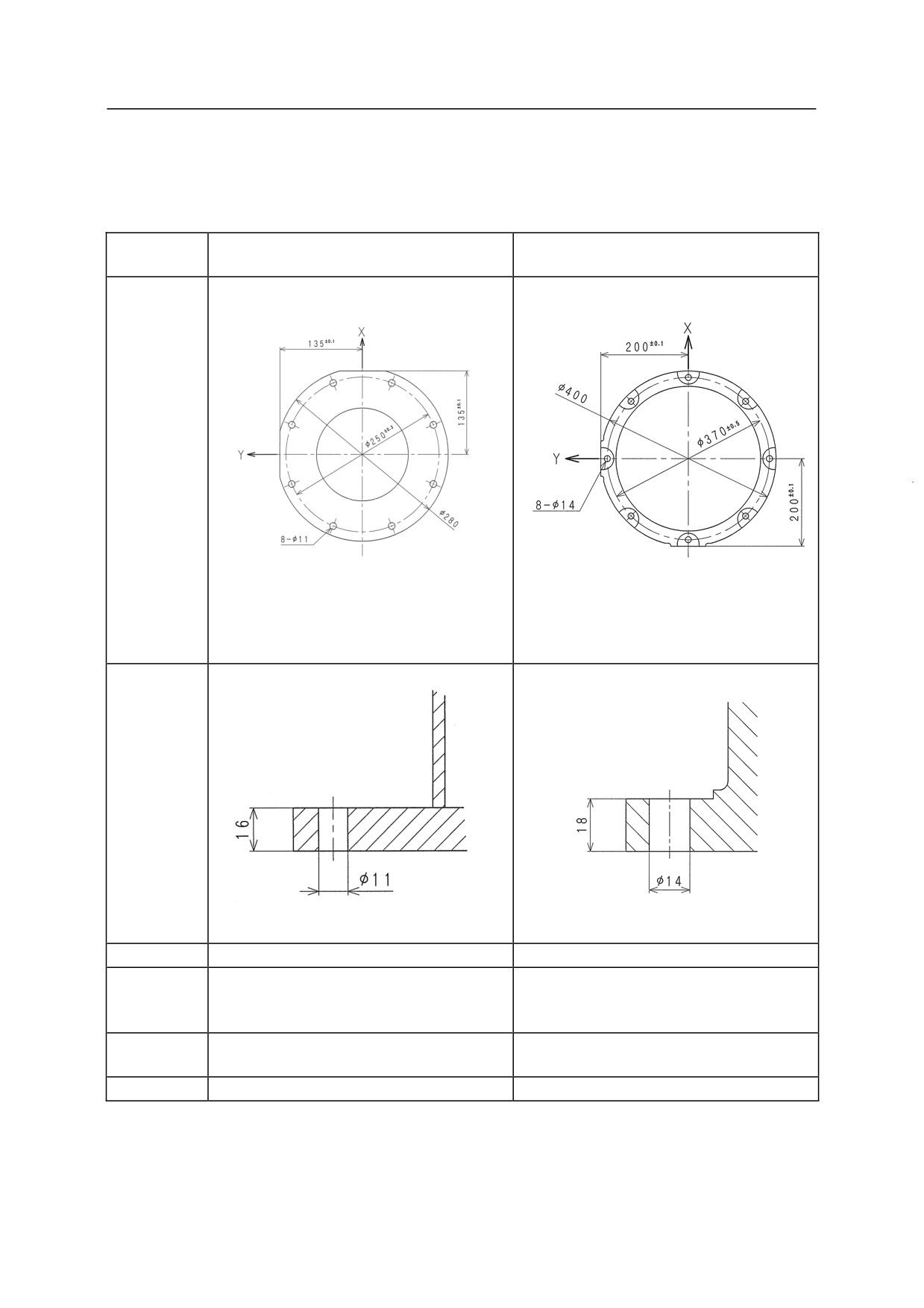
Dimensions of Robot Pedestal
When installing a robot on the pedestal, fix the pedestal with high tension bolts through the bolt holes.
RS06L, RS10N, RS10L, RS20N,
Model
RS05N, RS05L, RA05L, RC05L
RA06L, RA10N, RA10L, RA20N
Dimensions
for
installation
Cross-
section
of
installation
section
Bolt hole
8-11
8-14
High
8-M10
8-M12
tension
Material: SCM435
Material: SCM435
bolt
Strength class: 10.9 min
Strength class: 10.9 min
Tightening
56.8 Nm
98 Nm
torque
Levelness
Within 5°
Within 5°
26
R Series
6 Dimensions of Robot Pedestal
Kawasaki Robot Installation and Connection Manual
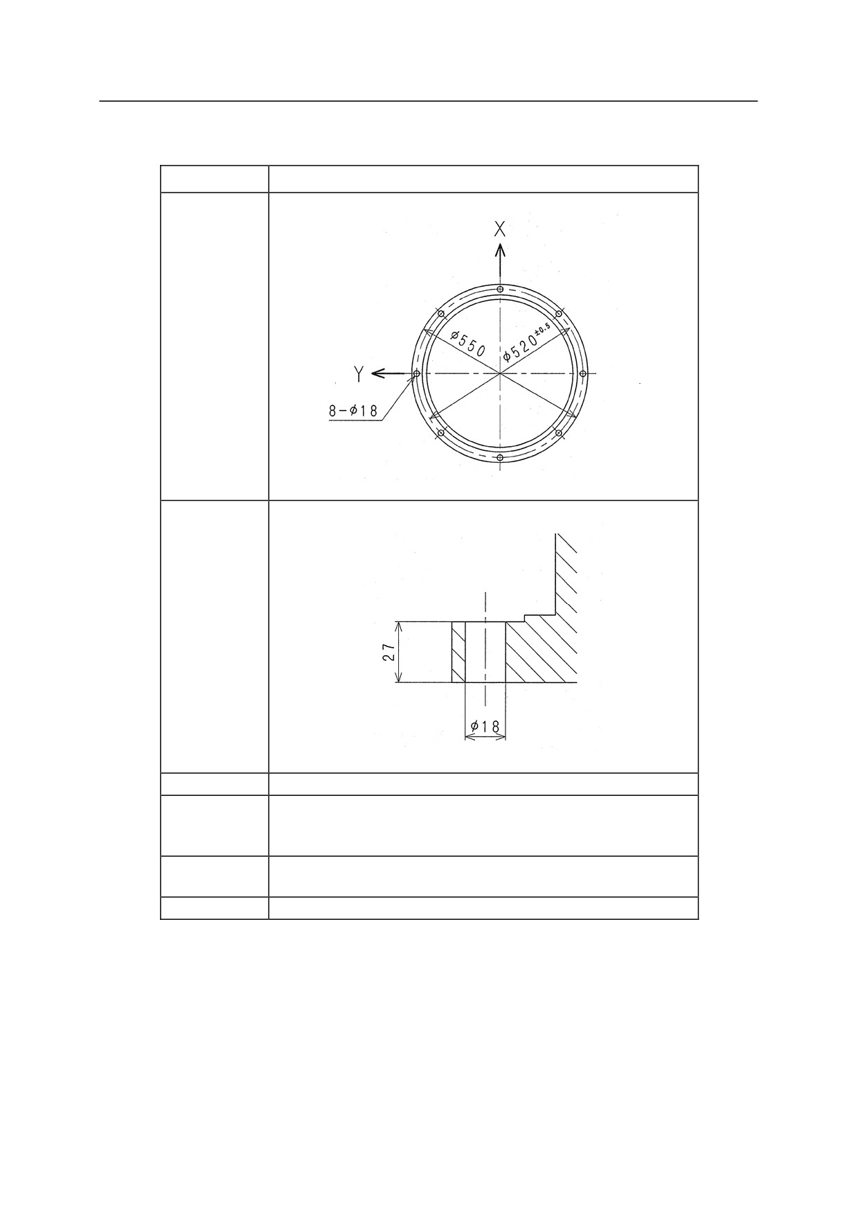
When installing a robot on the pedestal, fix the pedestal with high tension bolts through the bolt holes.
Model
RS15X, RS30N, RS50N, RS80N, RD80N
Dimensions
for
installation
Cross-section
of installation
section
Bolt hole
8-18
8-M16
High tension
Material: SCM435
bolt
Strength class: 10.9 min
Tightening
235 Nm
torque
Levelness
Within 5°
27
R Series
7 Installation Method
Kawasaki Robot Installation and Connection Manual
7
Installation Method
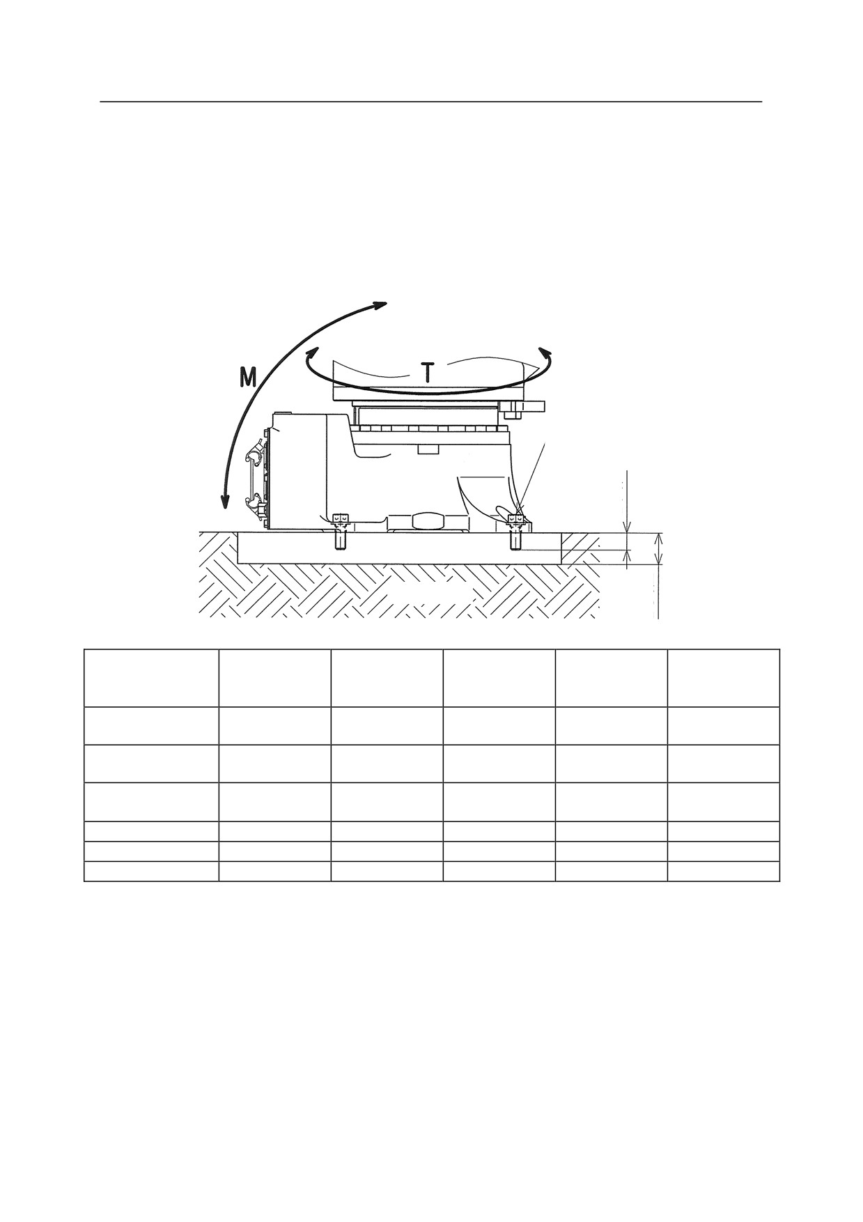
7.1 When Installing the Robot Directly on the Floor
In this case, bury steel plate of L2 thickness (See the table below.) in the concrete floor as shown in the
figure below or fix it with anchors. Fix the steel plate firmly enough to endure the reaction forces
produced by the robot.
Robot base installation bolt
L1
Steel plate
L2
Concrete
RS15X, RS30N,
RS05N, RS05L,
RS06L, RS10N,
RS10L, RS20N,
Model
RS07N, RS07L
RS50N, RS80N,
RA05L, RC05L
RA06L, RA10N
RA10L, RA20N
RD80N
M
1127 Nm
3223 Nm
1315 Nm
6300 Nm
15937 Nm
(Inversion moment)
T
849 Nm
2168 Nm
991 Nm
5614 Nm
12101 Nm
(Rotating torque)
Robot base installation
4-M8
4-M16
4-M10
4-M16
8-M16
bolt
Tightening torque
29.4 Nm
235 Nm
56.8 Nm
235 Nm
235 Nm
L1
Min. 12 mm
Min. 25 mm
Min. 13 mm
Min. 25 mm
Min. 25 mm
L2
Min. 14 mm
Min. 28 mm
Min. 14 mm
Min. 28 mm
Min. 28 mm
28
R Series
7 Installation Method
Kawasaki Robot Installation and Connection Manual
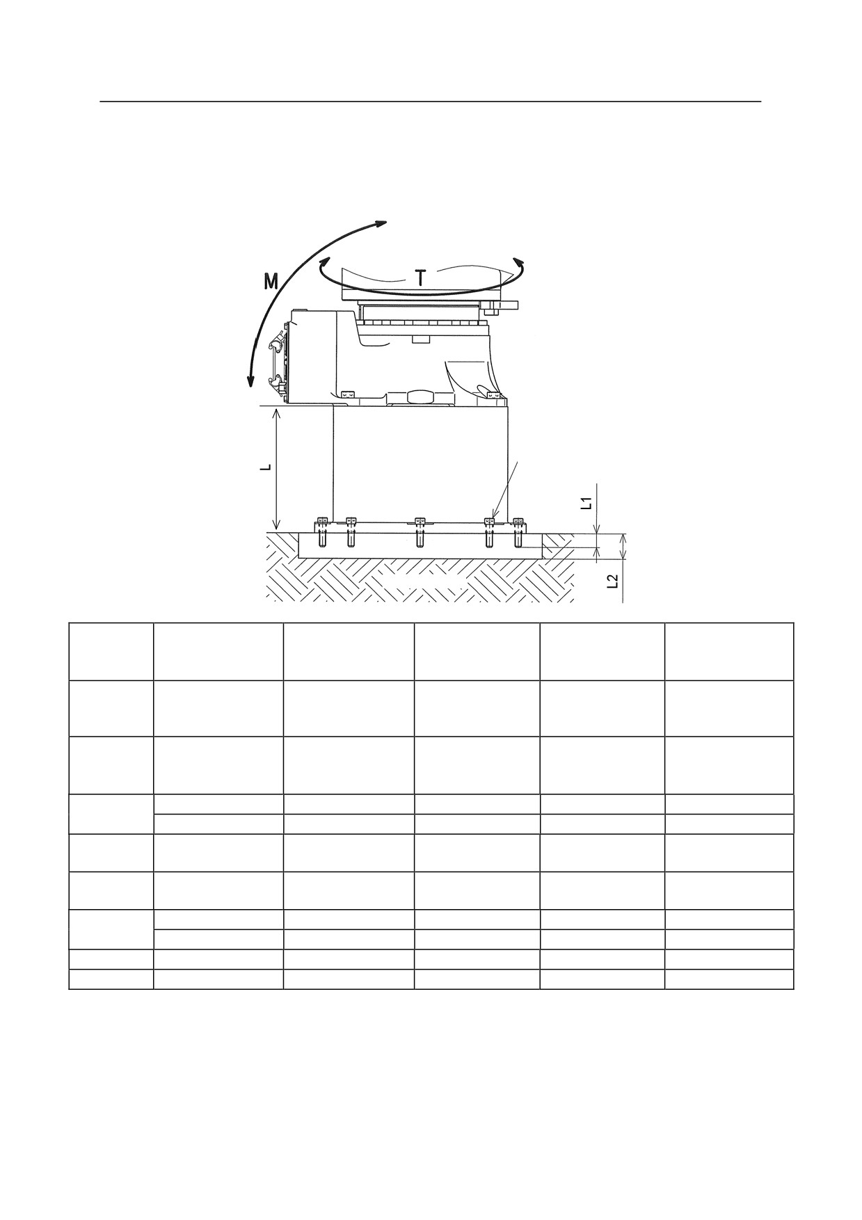
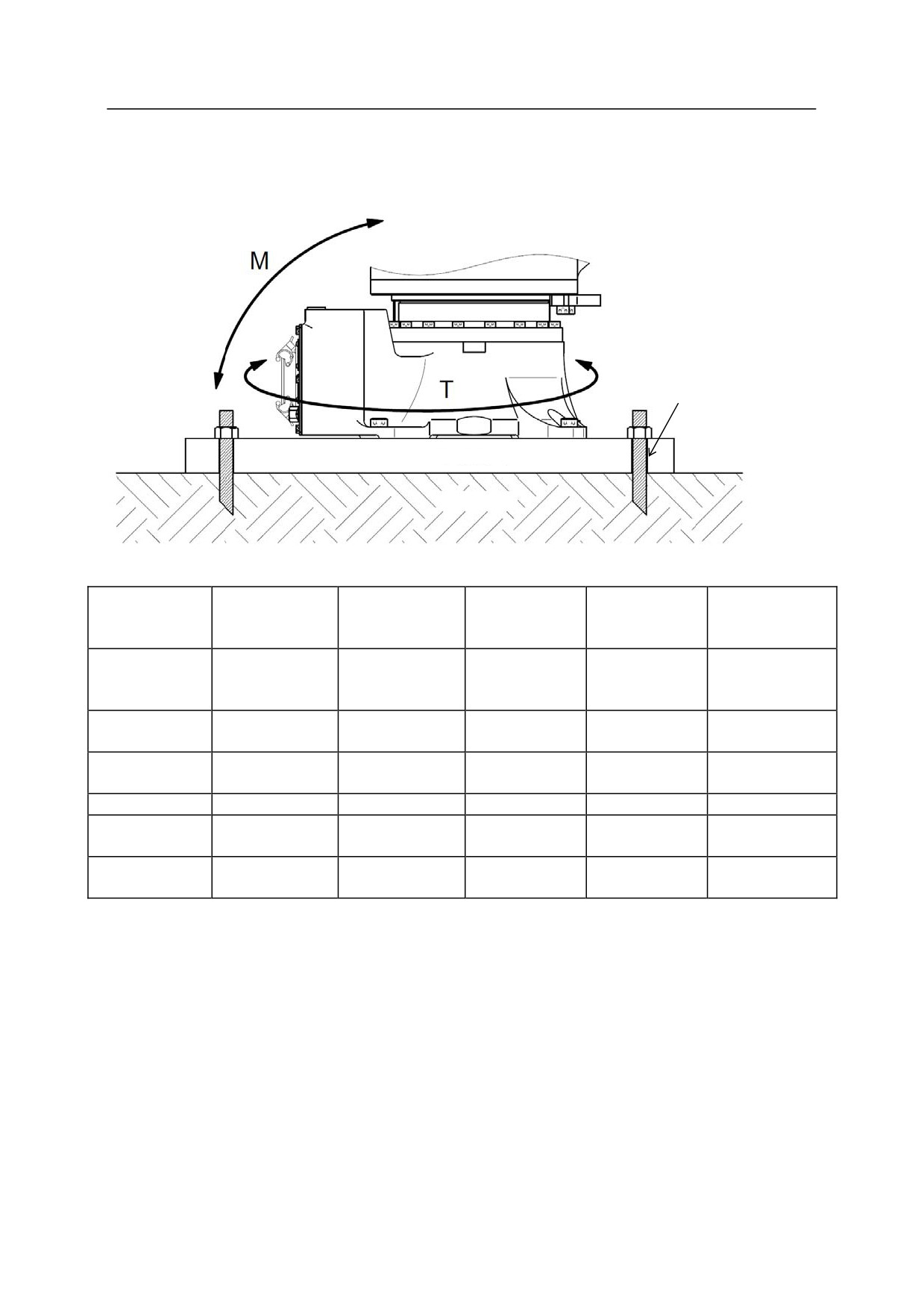
7.2 When Installing the Robot Pedestal on the Floor
In this case, the installation procedures are practically the same as the procedure shown in the section
7.1.
Pedestal installation bolt
Steel
plate
Concrete
RS15X, RS30N,
RS05N, RS05L,
RS06L, RS10N,
RS10L, RS20N,
Model
RS07N, RS07L
RS50N, RS80N,
RA05L, RC05L
RA06L, RA10N
RA10L, RA20N
RD80N
M
(Inversion
1127 Nm
3223 Nm
1315 Nm
6300 Nm
15937 Nm
moment)
T
(Rotating
849 Nm
2168 Nm
991 Nm
5614 Nm
12101 Nm
torque)
24 kg (L=600)
60 kg (L=600)
24 kg (L=600)
70 kg (L=600)
100 kg (L=600)
Pedestal mass
17 kg (L=300)
35 kg (L=300)
17 kg (L=300)
45 kg (L=300)
65 kg (L=300)
Pedestal
8-M10
8-M12
8-M10
8-M12
8-M16
installation bolt
Tightening
56.8 Nm
98 Nm
56.8 Nm
98 Nm
235 Nm
torque
600(60360-0082*)
600 (60360-1164*)
600(60360-2098*)
600(60360-1166*)
600(60360-1178*)
L
300(60360-0203*)
300 (60360-1165*)
300(60360-2099*)
300(60360-1167*)
300(60360-1179*)
L1
Min. 15 mm
Min. 18 mm
Min. 15 mm
Min. 18 mm
Min. 25 mm
L2
Min. 17 mm
Min. 20 mm
Min. 17 mm
Min. 20 mm
Min. 28 mm
NOTE* (
) indicates the part number of pedestal.
29
R Series
7 Installation Method
Kawasaki Robot Installation and Connection Manual
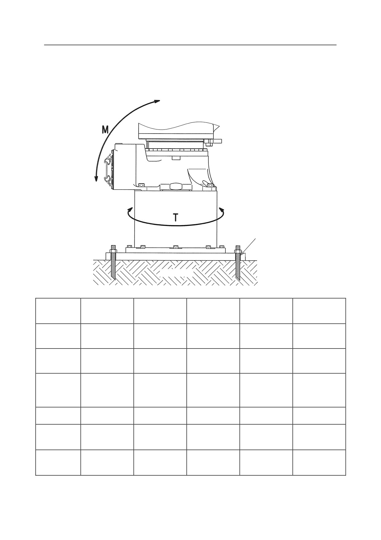
7.3 When Installing the Robot Base Plate on the Floor (Without Pedestal)
In this case, install the base plate on concrete floor or steel plate using bolt holes on the base plate.
Bolt hole
Base plate
Concrete
RS15X, RS30N,
RS05N, RS05L,
RS06L, RS10N,
RS10L, RS20N,
Model
RS07N, RS07L
RS50N, RS80N,
RA05L, RC05L
RA06L, RA10N
RA10L, RA20N
RD80N
M
(Inversion
1127 Nm
3223 Nm
1315 Nm
6300 Nm
15937 Nm
moment)
T
849 Nm
2168 Nm
991 Nm
5614 Nm
12101 Nm
(Rotating torque)
Part number of
60360-0081
60360-1201
60360-2102
60360-1203
60360-0086
base plate
Base plate mass
20 kg
110 kg
20 kg
110 kg
110 kg
Base plate
4-14
4-20
4-14
4-20
4-26
installation hole
(300 300)
(PCD800)
(300 300)
(PCD800)
(PCD800)
Base plate
400 400 16
750 750 25
400 400 16
750 750 25
750 750 25
dimension (mm)
30
R Series
7 Installation Method
Kawasaki Robot Installation and Connection Manual
7.4 When Installing the Robot Base Plate on the Floor
In this case, install the base plate on concrete floor or steel plate using bolt holes on the base plate.
Bolt hole
Base plate
Concrete
RS15X, RS30N,
RS05N, RS05L,
RS06L, RS10N,
RS10L, RS20N,
Model
RS07N, RS07L
RS50N, RS80N,
RA05L, RC05L
RA06L, RA10N
RA10L, RA20N
RD80N
M
(Inversion
1127 Nm
3223 Nm
1315 Nm
6300 Nm
15937 Nm
moment)
T
(Rotating
849 Nm
2168 Nm
991 Nm
5614 Nm
12101 Nm
torque)
Part number of
pedestal
60360-0081
60360-1005
60360-2102
60360-1005
60360-0085
installation
base plate
Base plate
20 kg
110 kg
20 kg
110 kg
110 kg
mass
Base plate
4-14
4-20
4-14
4-20
4-26
installation
(300 300)
(PCD800)
(300 300)
(PCD800)
(PCD800)
hole
Base plate
dimension
400 400 16
750 750 25
400 400 16
750 750 25
750 750 25
(mm)
31
R Series
8 Mounting of Tools
Kawasaki Robot Installation and Connection Manual
8
Mounting of Tools
㸟
WARNING
Prior to mounting tools, etc. on the robot, turn OFF the controller power switch
and the external power switch. Display signs indicating clearly “Installation and
connection in progress”, and lockout/tagout the external power switch to prevent
personnel from accidentally turning ON the power.
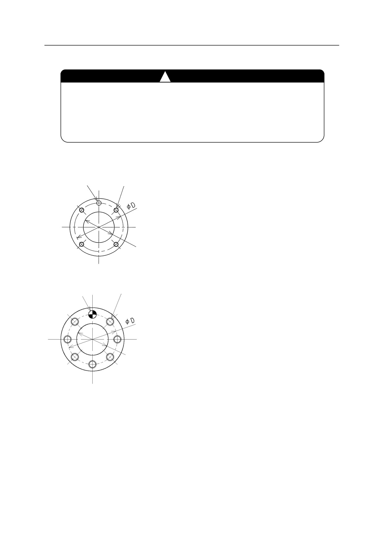
8.1 Dimensions of Wrist End
Pin hole
In the robot arm end section, a flange is
Tap holes
provided on which hand, gun, or other tools are
mounted. Screw the mounting bolts into the tap
holes on the circumference of D on the flange,
referring to the figure on the left. Moreover,
position the tool by utilizing the pin hole and
Spigot hole
the spigot hole.
Pin hole
Tap holes
Spigot hole
RS07N, RS07L
32
R Series
8 Mounting of Tools
Kawasaki Robot Installation and Connection Manual
8.2 Specification of Mounting Bolt
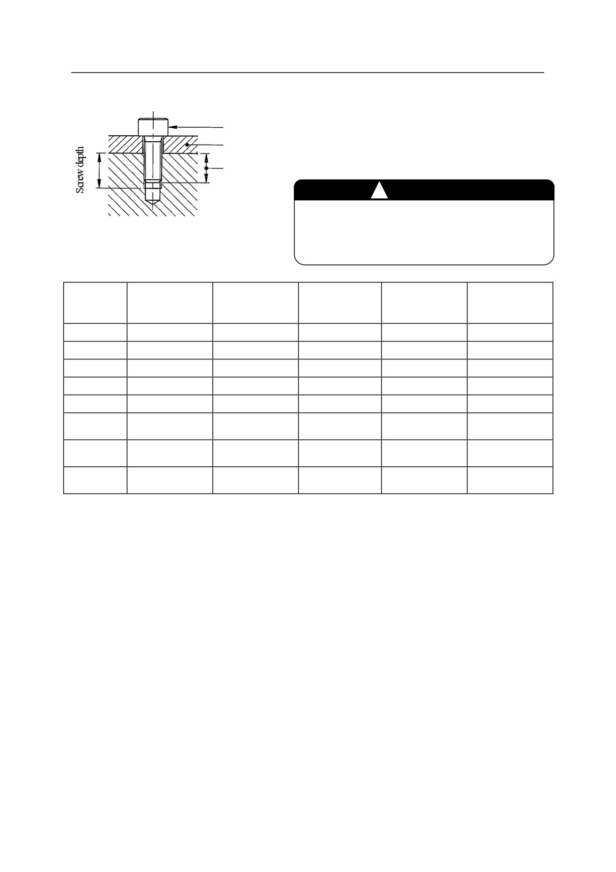
Select mounting bolts with proper length to
Mounting bolt
secure the specified screwing depth. Use high
Tool parts
tension mounting bolt and tighten them to the
specified torque.
Screwing depth
㸟
CAUTION
If the screwing depth has exceeded the specified
value, the mounting bolt might bottom out, and
the tool will not be fixed securely.
RS10L, RS15X,
RS05N, RS05L,
RS06L, RS10N,
RS30N, RS50N,
Model
RS07N, RS07L
RS20N, RA10L,
RA05L, RC05L
RA06L, RA10N
RS80N, RD80N
RA20N
Tapped holes
4-M5
4-M6
7-M5
4-M6
6-M8
D
31.5
40
31.5
63
80
Pin hole
5H7 Depth 8
6H7 Depth 6
5H7 Depth 6
6H7 Depth 6
8H7 Depth 8
Spigot hole
20H7 Depth 3
25H7 Depth 6
20H7 Depth 4
40H7 Depth 6
50H7 Depth 6
Screw depth
8 mm
8 mm
7 mm
9 mm
13 mm
Screwing
6 to 7 mm
6 to 7 mm
5 to 6mm
7 to 8 mm
8 to 12 mm
depth
High tension
SCM435, 10.9 min
SCM435, 10.9 min
SCM435, 10.9 min
SCM435, 10.9 min
SCM435, 10.9 min
bolt
Tightening
6.9 Nm
11.8 Nm
6.9 Nm
11.8 Nm
29.4 Nm
torque
33
R Series
8 Mounting of Tools
Kawasaki Robot Installation and Connection Manual
8.3 Load Capacity
Load mass applicable to robot is specified for each model and includes the mass of tool, etc. Applicable
load torque and moment of inertia around wrist axes (JT4, JT5, and JT6) are also specified. Strictly
observe the following restrictions on them.
㸟
CAUTION
Using the robot beyond its specified load may result in degradation of
movement performance and shortening of machine service life. The load
mass includes the tool mass such as hand, tool changer, shock absorber,
etc. If using the robot in excess of its load capacity, first contact
Kawasaki without fail.
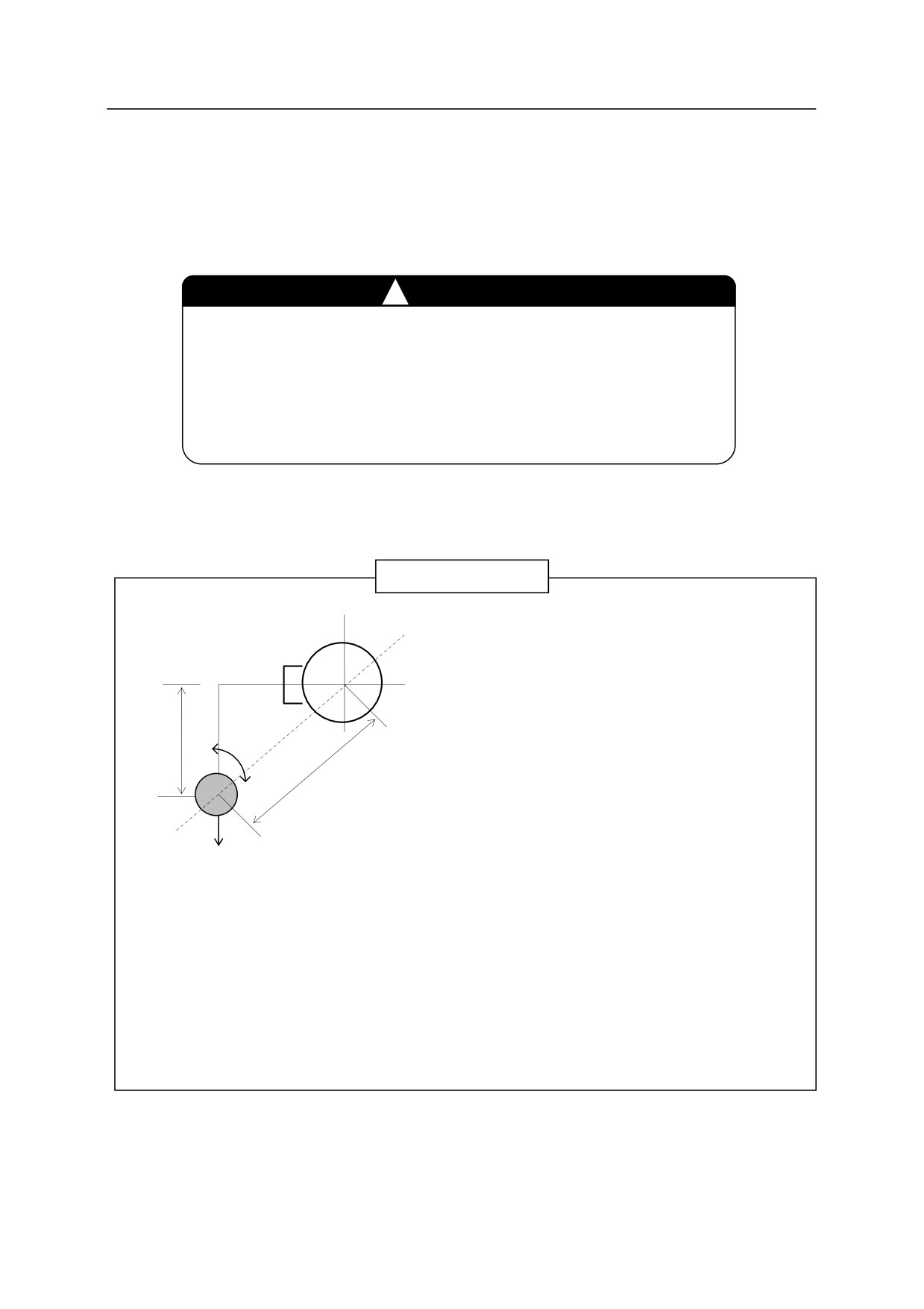
The load torque and the moment of inertia can be calculated by the expression below:
Calculation Expression
Load mass
: M≦Mmax. (kg)
(including tool)
Load torque
: T=9.8ML (Nm)
L6(m)
IG
Load moment of inertia: I=ML2+IG (kgm2)
L4, 5(m)
Mmax: Maximum load mass: See Section 3.2.
M(kg)
L: Length from axis rotation
L4, 5
: Length from JT4(5) axis rotation
center to load center of
center to load center of gravity.
gravity.
(Unit: m)
IG: Moment of inertia around center of
gravity. (Unit: kgm2)
L6: Length from JT6 axis
rotation center to load center
of gravity.
If calculation of load is made by dividing the load into construction parts, such as tools and
workpieces, use the total calculation values of each part as load torque and moment of inertia.
34
R Series
8 Mounting of Tools
Kawasaki Robot Installation and Connection Manual
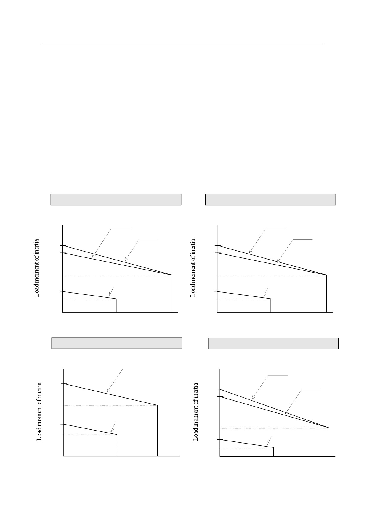
Regarding the load on the robot wrist section, meet the following restriction conditions:
1.
The load mass including tool mass should be less than the following value.
RS05 = 5 kg, RS06 = 6 kg, RS07 = 7 kg, RS10 = 10 kg, RS15 = 15 kg, RS20 = 20 kg,
RS30 = 30 kg, RS50 = 50 kg, RS80 = 80 kg, RD80 = 80 kg
2.
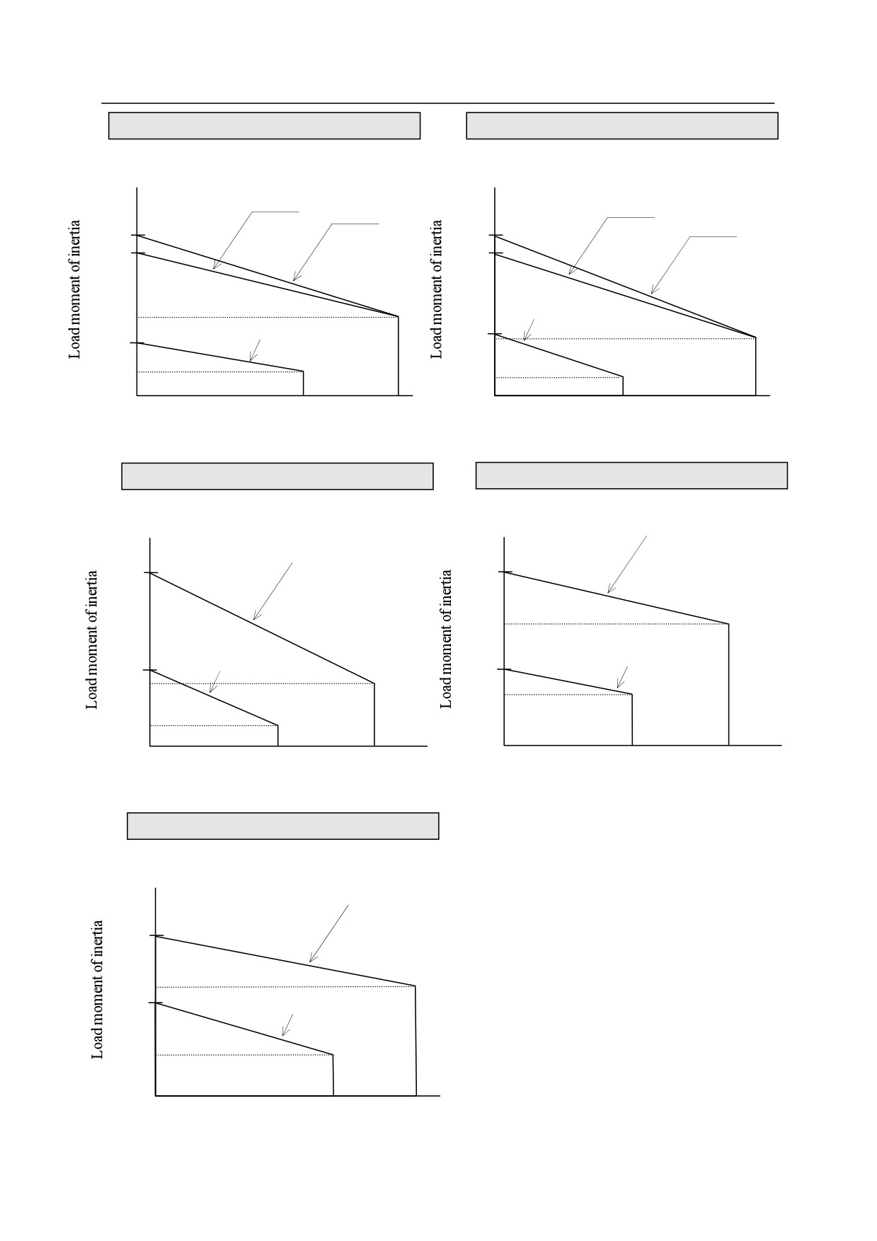
The load torque and the moment of inertia around each wrist axis (JT4, JT5, and JT6) should be
within the following restriction*:
NOTE* Load moment of inertia exceeding the restriction may be acceptable. In this case, ensure to
specify the load. (However, the robot movement may become slow because of optimizing
acceleration and deceleration.) See AS Language Reference Manual for setting the load.
Operating the robot with wrong settings may result in degradation of movement performance
and shortening of machine service life.
RS05N, RS05L, RA05L, RC05L
RS06L, RA06L
kgm2
kgm2
JT4
JT4
JT5
JT5
0.857
0.817
0.719
0.803
0.4
0.45
JT6
JT6
0.257
0.25
0.12
0.14
7
12.3
7.5
13
Nm
Nm
Load torque
Load torque
RS07N, RS07L
RS10N, RS10L, RA10N, RA10L
kgm2
JT4, JT5
kgm2
JT4
0.71
JT5
1.49
1.46
0.5
JT6
0.3
0.7
JT6
0.2
0.388
0.2
10
17
10
22
Nm
Nm
Load torque
Load torque
35
R Series
8 Mounting of Tools
Kawasaki Robot Installation and Connection Manual
RS15X
RS20N, RA20N
kgm2
kgm2
JT4
JT4
JT5
JT5
1.698
2.56
1.513
2.28
JT6
0.8
JT6
0.965
0.576
0.9
0.25
0.3
22
34
29
45
Nm
Nm
Load torque
Load torque
RS30N
RS50N
kgm2
kgm2
JT4, JT5
JT4, JT5
40.40
40.40
28
JT6
JT6
17.16
17.16
16.8
11
6.6
130
210
130
210
Nm
Nm
Load torque
Load torque
RS80N
kgm2
JT4, JT5
58.97
34.00
30.61
JT6
13.70
194
336
Nm
Load torque
36
R Series
8 Mounting of Tools
Kawasaki Robot Installation and Connection Manual
For RD80N
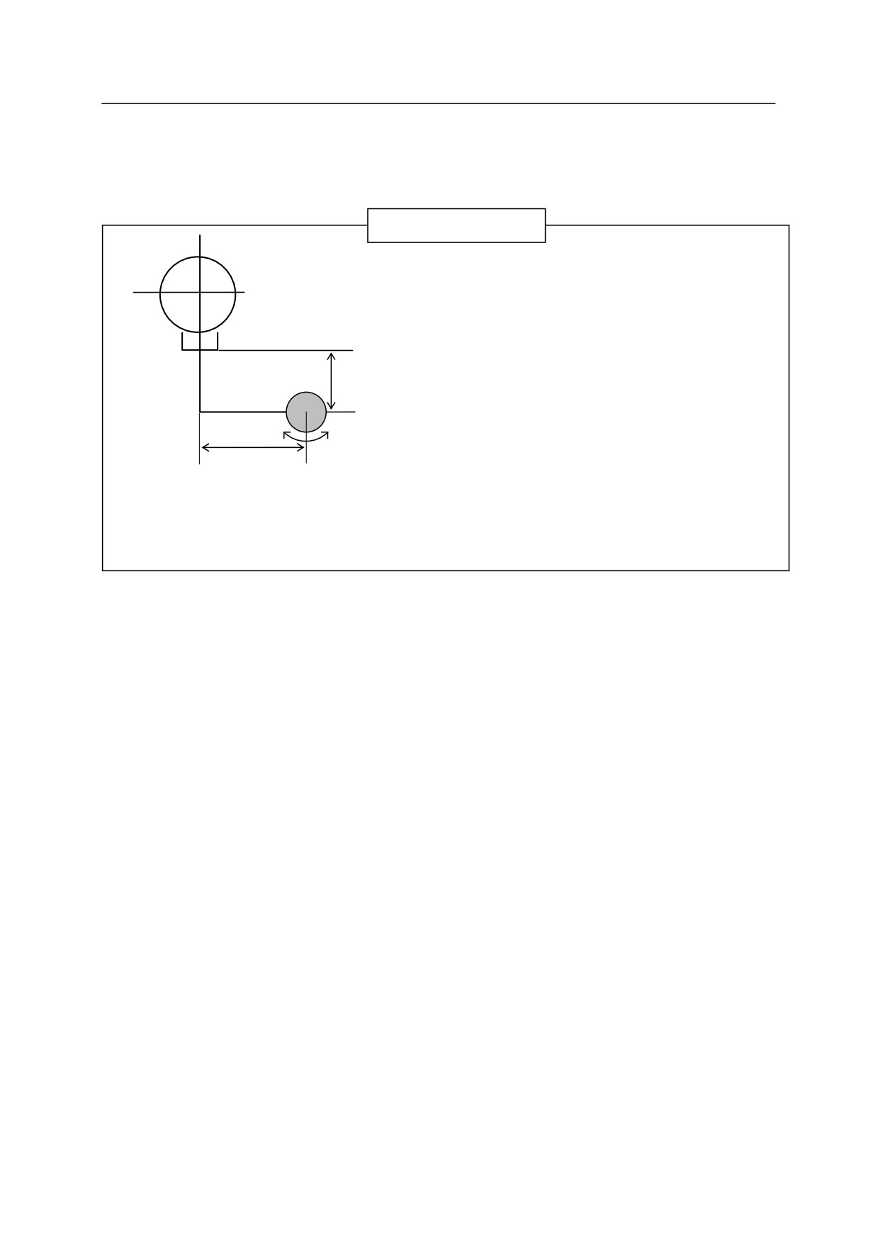
The load torque and the moment of inertia in wrist section should be calculated by expressions below.
Calculation Expression
Load mass (including tool): M≤Mmax. (kg)
Load torque: not specified
Load moment of inertia: I=ML2+IG (kgm2) ≤Imax (kgm2)
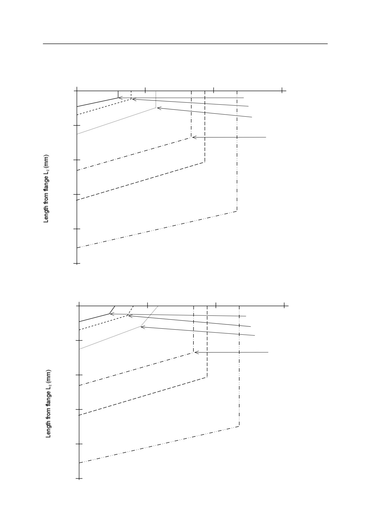
Center position of load mass (L4, Lz): See diagrams below.
Mmax.: Maximum load mass 80 (kg)
Lz
(m)
Imax.: Maximum load moment of inertia 13.7 (kgm2)
IG: Moment of inertia around center of gravity (kgm2)
L4 (m)
IG
Lz: Length from flange to load center of load mass (m)
L4: Length from JT4 axis rotating center to load center of load mass
M (kg)
(m)
When calculating the load by dividing it into sections (for example, tool section, workpiece section,
etc.), evaluate the moment of inertia from the sum of all the sections.
Strictly observe the following restrictions applied to wrist sections.
1. The allowable load mass including tools should be less than the Mmax. above.
2. Restrictions are applied to the load moment of inertia in wrist section (JT4). The load moment of
inertia should be below 13.7 kgm2.
3. Restrictions are applied to the center of load mass. The center should be positioned within the
allowable range. There are two diagrams for the cases; when moving with JT5 faced vertically
down (0) and when moving with JT5 tilted (within ±10 of vertical down). In both cases, keep the
center of gravity within the allowable range for load of 10 kg even when the load mass is below 10
kg. See the next page.
37
R Series
8 Mounting of Tools
Kawasaki Robot Installation and Connection Manual
Diagram of load on wrist section (JT5:0°)
Length from JT4 axis rotating center L4 (mm)
0
500
1000
1500
267.5
356.7
535.0
827.7
955.7
1170.5
0
80 kg
(267.5, 104.8)
220.7
(356.7, 168.8)
60 kg
323.4
(535.0, 296.8)
500
40 kg
528.7
(827.7, 786.0)
20 kg
1000
1144.7
(955.7, 1141.2)
15 kg
1500
1555.4
(1170.5, 1869.5)
2000
10 kg or less
2376.8
2500
Diagram of load on wrist section (JT5: within ±10°)
Length from JT4 axis rotating center L4 (mm)
0
500
1000
1500
242.5
333.1
514.2
827.7
955.7
1170.5
0
80 kg
(220.5, 125.2)
220.7
60 kg
(298.9, 193.8)
323.4
(455.8, 331.2)
500
40 kg
528.7
(827.7, 786.0)
20 kg
1000
1144.7
(955.7, 1141.2)
15 kg
1500
1555.4
(1170.5, 1869.5)
2000
10 kg or less
2376.8
2500
38
R Series
9 Mounting External Equipment
Kawasaki Robot Installation and Connection Manual
9
Mounting External Equipment
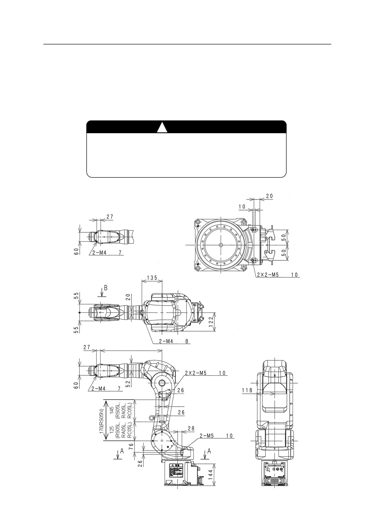
9.1 Service Tapped Hole Positions
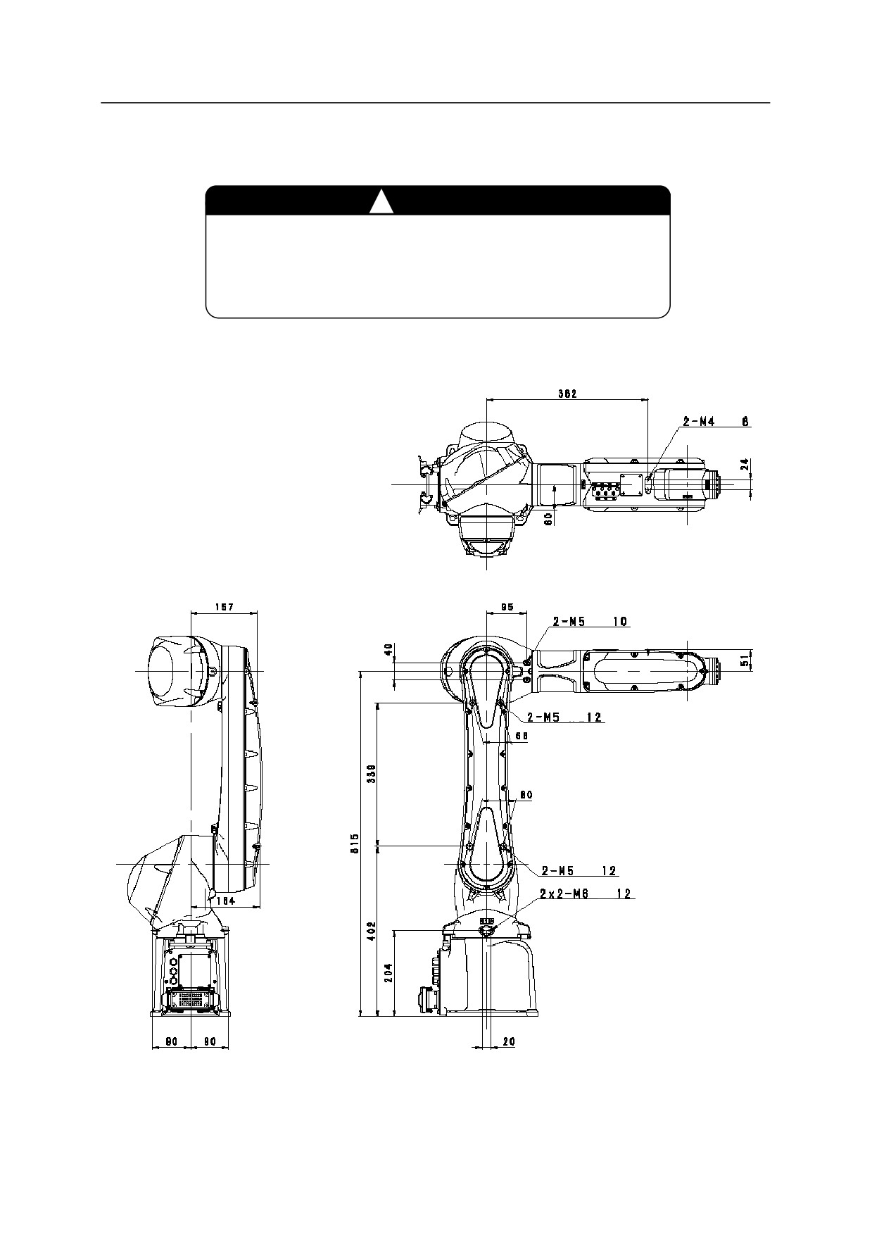
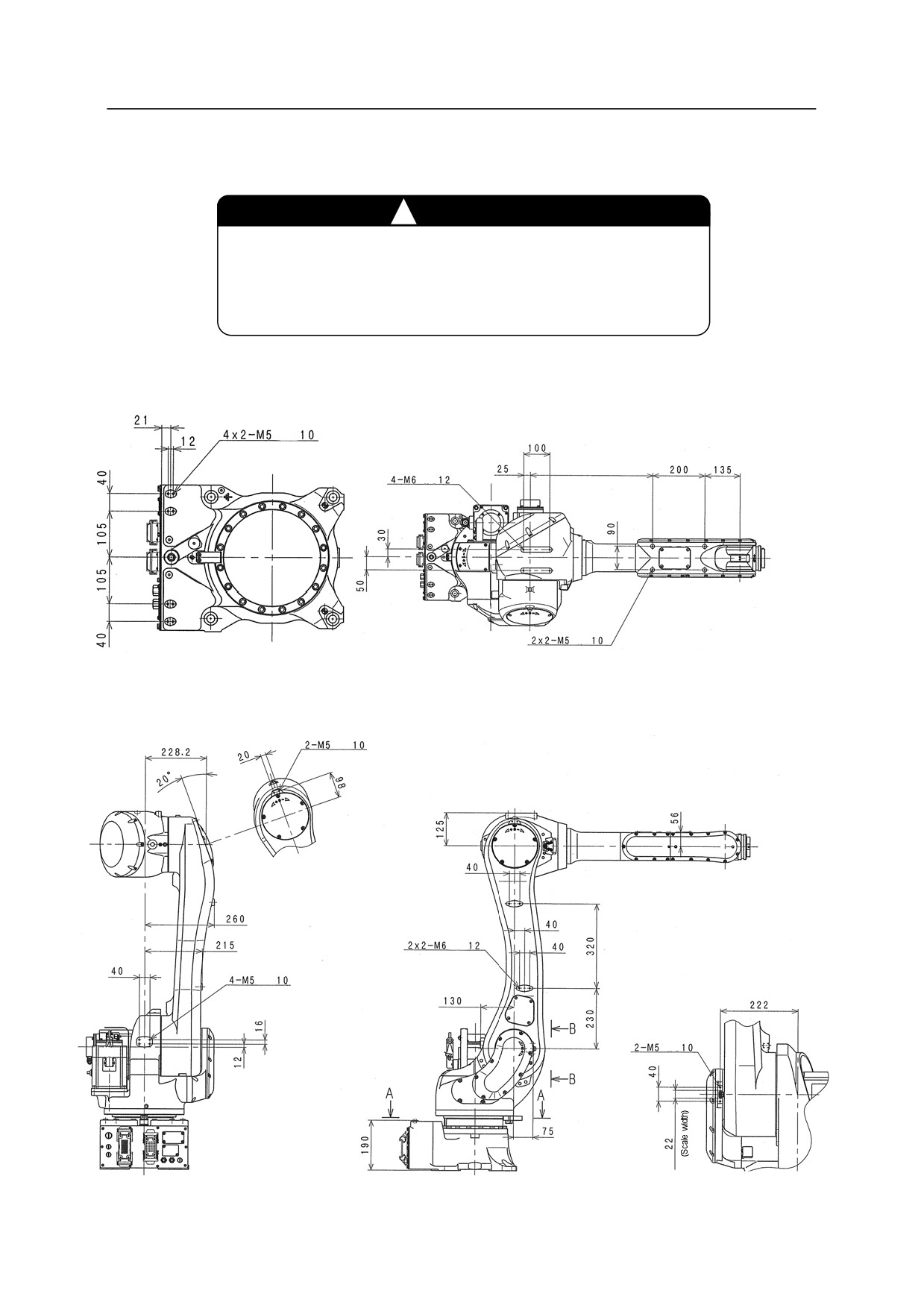
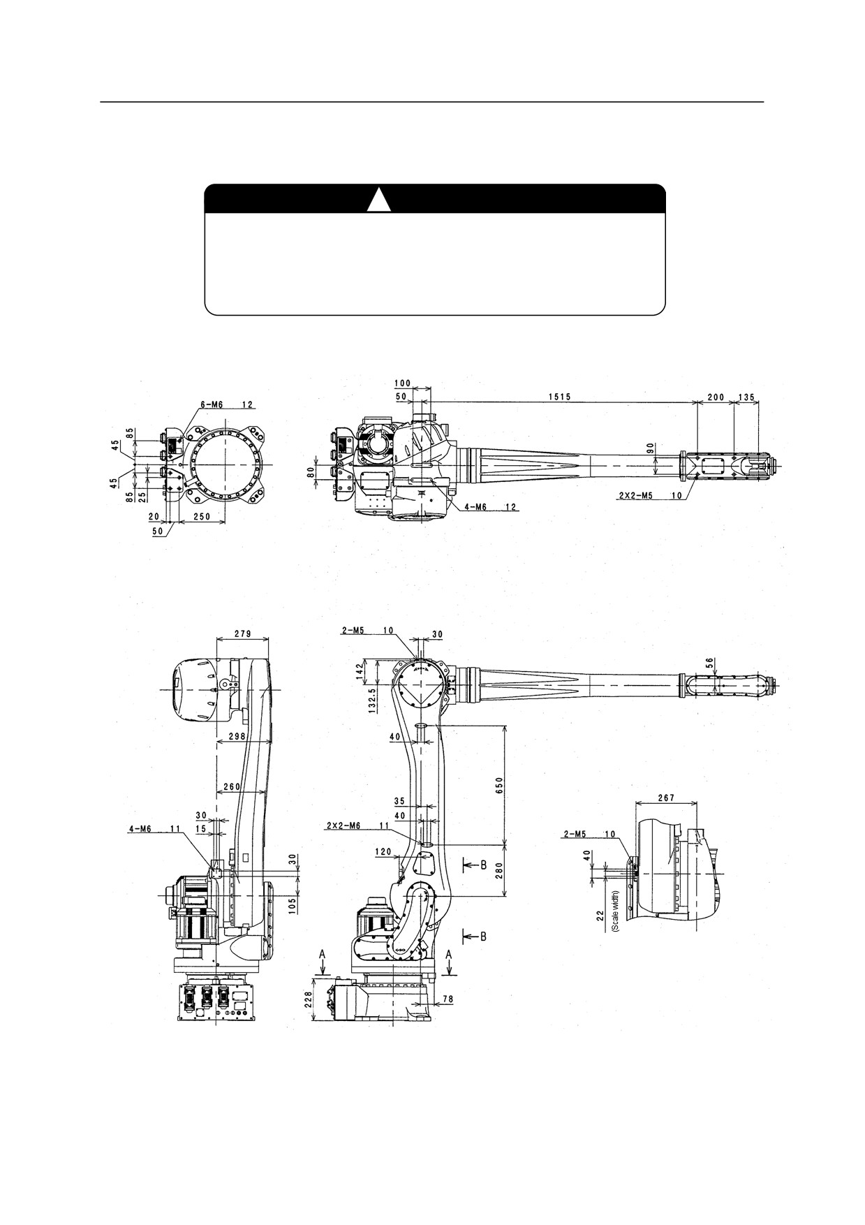
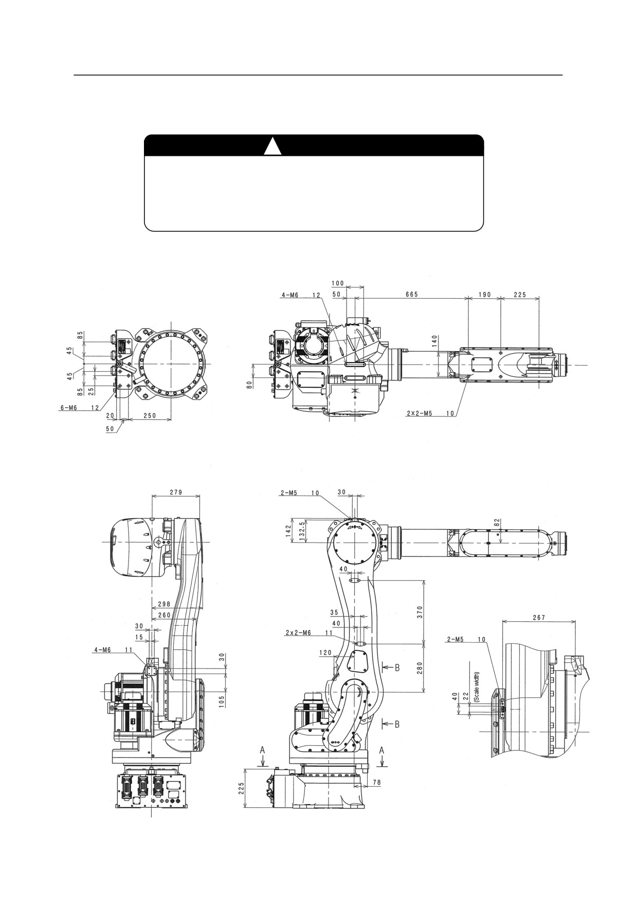
Service tapped holes shown in the figure below are available to mount wiring brackets and external
equipment on each part of robot arm.
㸟
CAUTION
Check the robot movement very carefully and confirm that
mounted brackets and external equipment do not interfere
with peripheral equipment and robot arm itself.
RS05N, RS05L, RA05L, RC05L
D
View B-B
D
Cross section A-A
310(RS05N)
410(RS05L,
D
RA05L,RC05L)
D
D
10(RS05N)
15(RS05L,RA05L,RC05L)
D
39
R Series
9 Mounting External Equipment
Kawasaki Robot Installation and Connection Manual
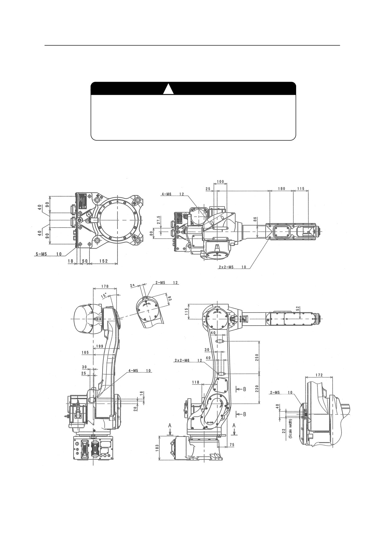
Service tapped holes shown in the figure below are available to mount wiring brackets and external
equipment on each part of robot arm.
㸟
CAUTION
Check the robot movement very carefully and confirm that
mounted brackets and external equipment do not interfere
with peripheral equipment and robot arm itself.
RS06L, RS10N, RA06L, RA10N
605(RS06L, RA06L)
405(RS10N, RA10N)
D
D
D
Cross section A-A
D
D
D
D
View B-B
40
R Series
9 Mounting External Equipment
Kawasaki Robot Installation and Connection Manual
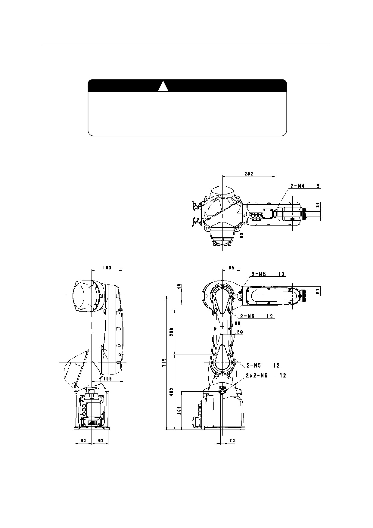
Service tapped holes shown in the figure below are available to mount wiring brackets and external
equipment on each part of robot arm.
㸟
CAUTION
Check the robot movement very carefully and confirm that
mounted brackets and external equipment do not interfere
with peripheral equipment and robot arm itself.
RS07N
D
D
D
D
D
41
R Series
9 Mounting External Equipment
Kawasaki Robot Installation and Connection Manual
Service tapped holes shown in the figure below are available to mount wiring brackets and external
equipment on each part of robot arm.
㸟
CAUTION
Check the robot movement very carefully and confirm that
mounted brackets and external equipment do not interfere
with peripheral equipment and robot arm itself.
RS07L
D
D
D
D
D
42
R Series
9 Mounting External Equipment
Kawasaki Robot Installation and Connection Manual
Service tapped holes shown in the figure below are available to mount wiring brackets and external
equipment on each part of robot arm.
㸟
CAUTION
Check the robot movement very carefully and confirm that
mounted brackets and external equipment do not interfere
with peripheral equipment and robot arm itself.
RS10L, RS20N, RA10L, RA20N
D
670(RS10L, RA10L)
470(RS20N, RA20N)
D
D
Cross section A-A
D
D
D
D
View B-B
43
R Series
9 Mounting External Equipment
Kawasaki Robot Installation and Connection Manual
Service tapped holes shown in the figure below are available to mount wiring brackets and external
equipment on each part of robot arm.
㸟
CAUTION
Check the robot movement very carefully and confirm that
mounted brackets and external equipment do not interfere
with peripheral equipment and robot arm itself.
RS15X
D
D
D
Cross section A-A
D
D
D
D
View B-B
44
R Series
9 Mounting External Equipment
Kawasaki Robot Installation and Connection Manual
Service tapped holes shown in the figure below are available to mount wiring brackets and external
equipment on each part of robot arm.
㸟
CAUTION
Check the robot movement very carefully and confirm that
mounted brackets and external equipment do not interfere
with peripheral equipment and robot arm itself.
RS30N, RS50N, RS80N, RD80L
D
D
D
Cross section A-A
D
D
D
D
View B-B
45
R Series
9 Mounting External Equipment
Kawasaki Robot Installation and Connection Manual
9.2 Calculation of Load Caused by External Equipment
The load capacity is set for each arm model. Strictly observe the following restrictions of the load torque
and load moment of inertia on arm.
㸟
CAUTION
Check the robot movement very carefully and confirm that
mounted brackets and external equipment do not interfere
with peripheral equipment and robot arm itself.
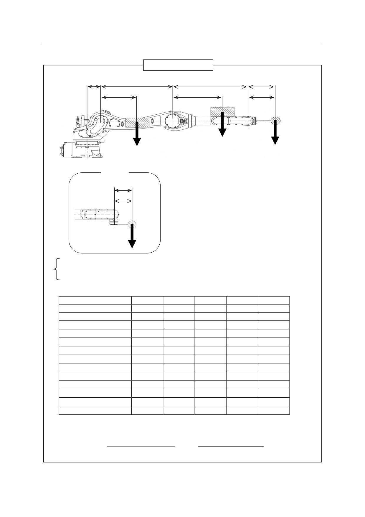
For JT2 and JT3, limit the total load torque on wrist end and arm not to exceed the maximum allowable
load torque. The load torque and the moment of inertia can be calculated by the expression on next
page.
46
R Series
9 Mounting External Equipment
Kawasaki Robot Installation and Connection Manual
Calculation Expression
L1
L2
L3
LW
l2
l3
lW
W3
W
W2
Wmax : Max. allowable load [kg]
W
: Load on wrist end [kg]
RD80N
W2
: Total load on lower arm [kg]
LW
W3
: Total load on upper arm [kg]
lW
lw
: Position of the center of the gravity for
load on wrist section [mm]
l2
: Position of the center of the gravity for
total load on lower arm [mm]
l3
: Position of the center of the gravity for
W
total load on upper arm [mm]
࣭JT3: W(L3+lw)+W3l3 ӌWmax(L3+LW)
࣭JT2: W(L2+L3+lw)+W3(L2+l3)+W2l2 ӌWmax(L2+L3+LW)
Use data in the table below for calculation.
L1 [mm]
L2 [mm]
L3 [mm]
Lw [mm]
Wmax
[kg]
RS05N
105
280
310
251
5
RS05L, RA05L, RC05L
105
380
410
251
5
RS06L, RA06L
100
650
900
221
6
RS07N
0
355
375
199
7
RS07L
0
455
475
199
7
RS10N, RA10N
100
650
700
224
10
RS10L, RA10L
150
770
1005
224
10
RS15X
150
1150
1850
230
15
RS20N, RA20N
150
770
805
230
20
RS30N
150
870
1080
714
30
RS50N
150
870
1080
428
50
RS80N
150
870
1080
428
80
RD80N
150
870
1080
220
80
However, do not exceed values below for W2 and W3.
W
(L
L
L
L
)
W
(L
L
L
L
)
max
1
2
3
W
max
1
2
3
W
W
W
3
2
L
1
L
2
L
1
47
R Series
10 Connection of Air System
Kawasaki Robot Installation and Connection Manual
10 Connection of Air System
10.1 Air Piping Arrangement
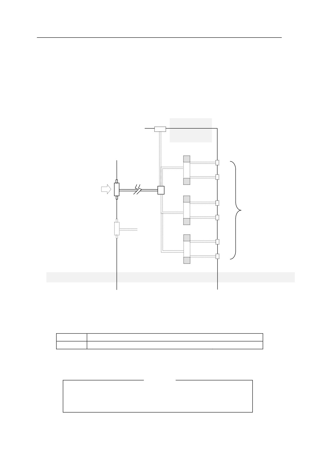
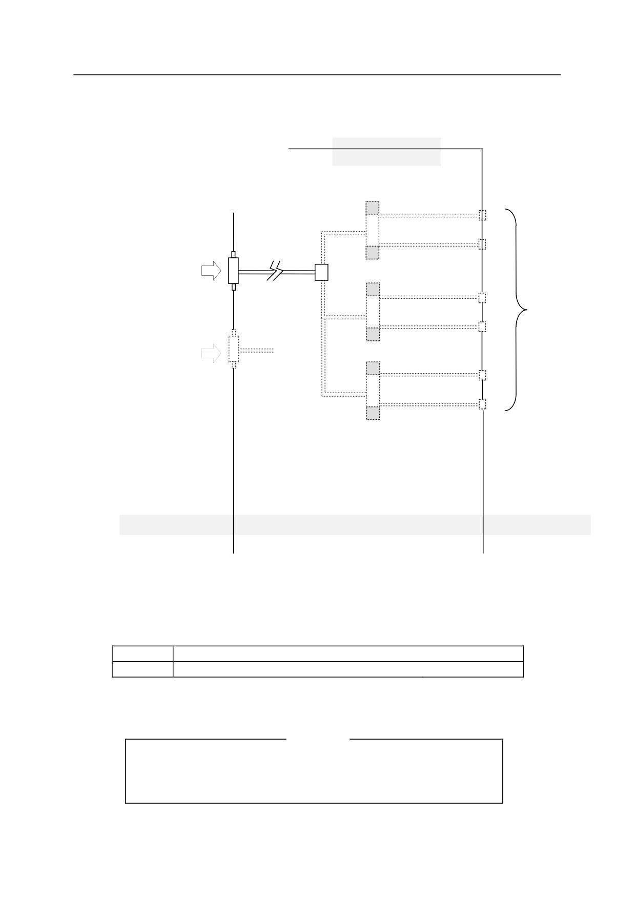
R series robot houses air piping and valves for driving the tool on the robot arm. The valves can be
turned ON/OFF by the Teach Pendant without using an interlock panel.
RS05N, RS05L, RA05L, RC05L, RS07N, RS07L
Outside of robot
arm
Inside of robot
arm
Valve
A1
Rc1/4
B1
A
Air inlet
(Input: 0.15 to 0.6 MPa
(21.7 to 87.0 psi))
A2
Air outlet
Rc1/4
B2
B
Air inlet for purging
(Input: 0.03 MPa (4.35 psi))
NOTE: Except RC05L
A3
B3
Robot base section
Inside of robot arm
Robot upper arm section
Optional equipment is shown by the dotted line (
).
The built-in valves are specified as follows:
Standard
No built-in valves
Option
Double solenoid/Single solenoid valves
3 units max.
Valve specification: CV value is 0.2 and the number of switching positions is 2.
[NOTE]
Valves that do not meet the above specifications cannot be mounted in
the arm. Please contact KHI for information on air system specifications
if such valves are used.
48
R Series
10 Connection of Air System
Kawasaki Robot Installation and Connection Manual
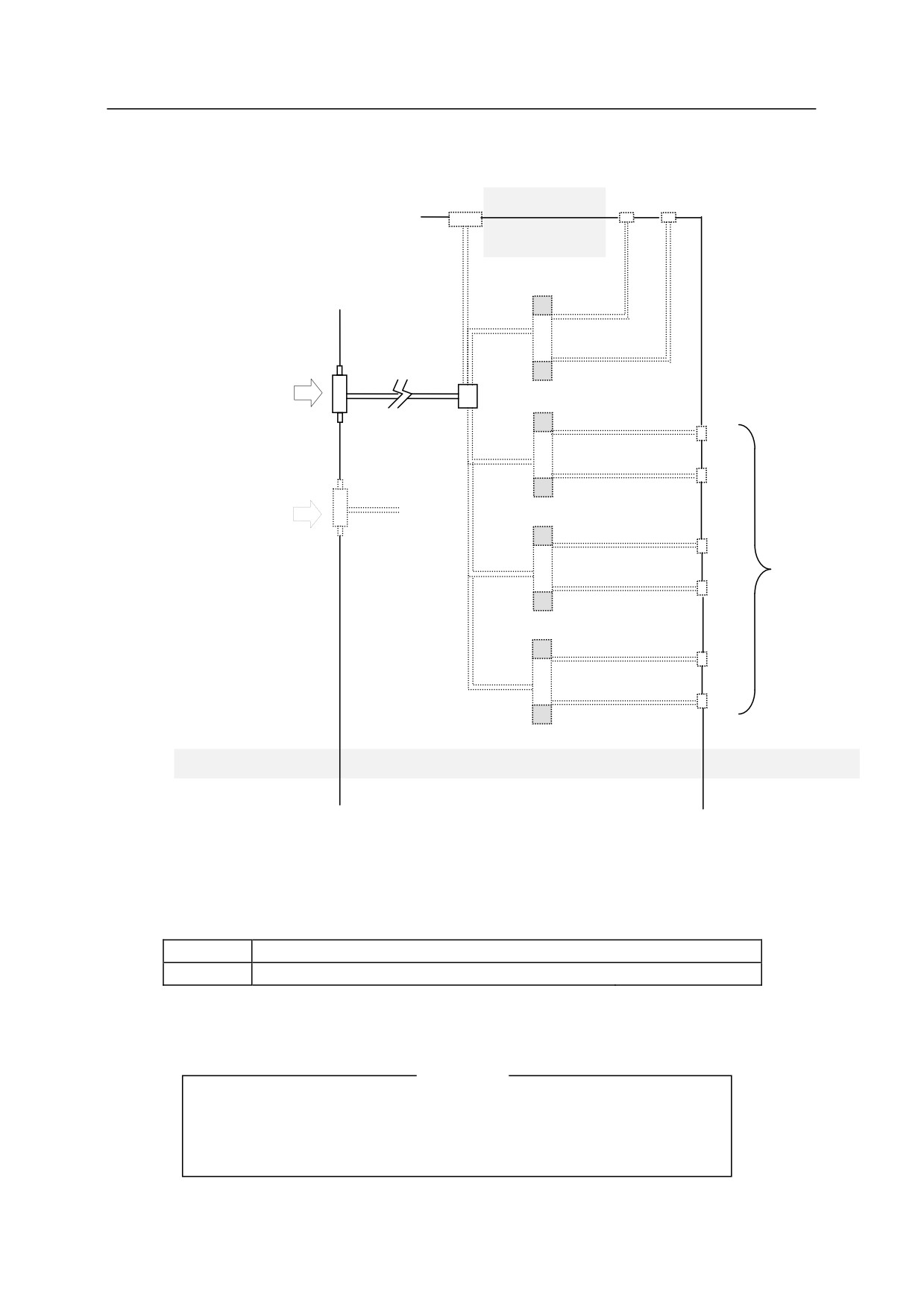
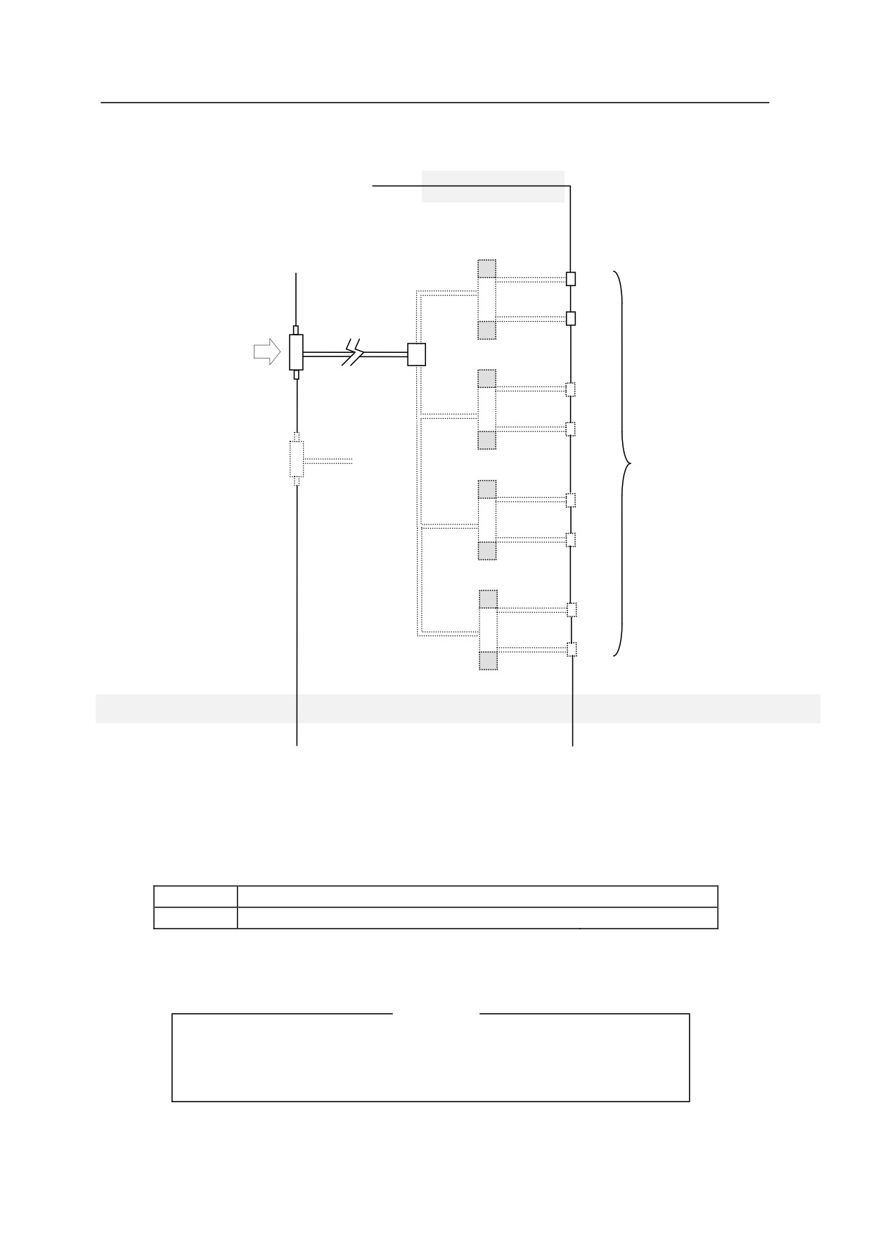
RS06L, RS10N
Air outlet
Outside of robot
A4 B4
arm
Inside of robot
arm
Valve
Rc3/8
A
Air inlet
(Input: 0.15 to 0.6 MPa
(21.7 to 87.0 psi))
A1
B1
B
Rc3/8
Air inlet for purging
(Input: 0.03 MPa (4.35 psi))
A2
Air outlet
B2
A3
B3
Robot base section
Inside of robot arm
Robot wrist section
Optional equipment is shown by the dotted line (
).
The built-in valves are specified as follows:
Standard
No built-in valves
Option
Double solenoid/Single solenoid valves
4 units max.
Valve specification: CV value is 0.2 and the number of switching positions is 2.
[NOTE]
Valves that do not meet the above specifications cannot be mounted in
the arm. Please contact KHI for information on air system specifications
if such valves are used.
49
R Series
10 Connection of Air System
Kawasaki Robot Installation and Connection Manual
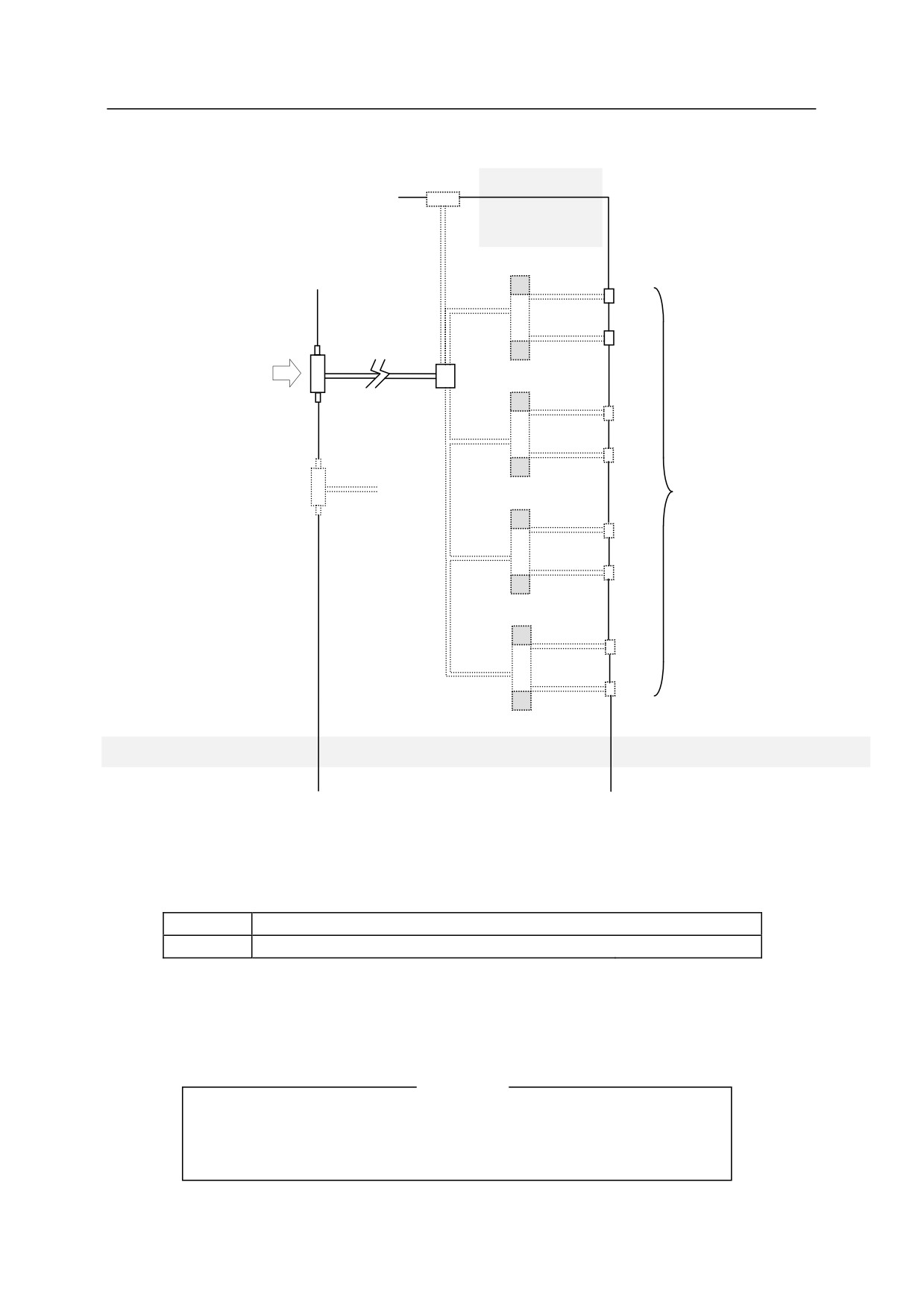
RS10L, RS15X, RS20N, RS30N, RS50N, RS80N, RD80N
Outside of robot
arm
Inside of robot
arm
Valve
A1
B1
A
Rc3/8
Air inlet
(Input:0.15 to 0.6 MPa
(21.7 to 87.0 psi))
A2
B2
Rc3/8
B
Air inlet for purging
Air outlet
(Input:0.03 MPa (4.35 psi))
A3
B3
A4
B4
Robot base section
Inside of robot arm
Robot wrist section
Optional equipment is shown by the dotted line (
).
The built-in valves are specified as follows:
Standard
No built-in valves
Option
Double solenoid/Single solenoid valves
4 units max.
Valve specification
For RS10L, RS20N: CV value is 0.2 and the number of switching positions is 2.
For the other models: CV value is 0.6 and the number of switching positions is 2.
[NOTE]
Valves that do not meet the above specifications cannot be mounted in
the arm. Please contact KHI for information on air system specifications
if such valves are used.
50
R Series
10 Connection of Air System
Kawasaki Robot Installation and Connection Manual
RA06L, RA10N
Outside of robot arm
Inside of robot arm
Valve
A1
B1
Rc3/8
A
Air inlet
(Input: 0.15 to 0.6 MPa
(21.7 to 87.0 psi))
A2
Air outlet
B2
B
Rc3/8
Air inlet for purging
(Input: 0.03 MPa (4.35 psi))
A3
B3
Robot base section
Inside of robot arm
Robot wrist section
Optional equipment is shown by the dotted line (
).
The built-in valves are specified as follows:
Standard
No built-in valves
Option
Double solenoid/Single solenoid valves
3 units max.
Valve specification: CV value is 0.2 and the number of switching positions is 2.
[NOTE]
Valves that do not meet the above specifications cannot be mounted in
the arm. Please contact KHI for information on air system specifications
if such valves are used.
51
R Series
10 Connection of Air System
Kawasaki Robot Installation and Connection Manual
RA10L, RA20N
Outside of robot arm
Inside of robot arm
Valve
A1
B1
A
Rc3/8
Air inlet
(Input:0.15 to 0.6 MPa
(21.7 to 87.0 psi))
A2
B2
B
Rc3/8
Air inlet for purging
Air outlet
(Input:0.03 MPa (4.35 psi))
A3
B3
A4
B4
Robot base section
Inside of robot arm
Robot wrist section
Optional equipment is shown by the dotted line (
).
The built-in valves are specified as follows:
Standard
No built-in valves
Option
Double solenoid/Single solenoid valves
4 units max.
Valve specification: CV value is 0.2 and the number of switching positions is 2.
[NOTE]
Valves that do not meet the above specifications cannot be mounted in
the arm. Please contact KHI for information on air system specifications
if such valves are used.
52
R Series
10 Connection of Air System
Kawasaki Robot Installation and Connection Manual
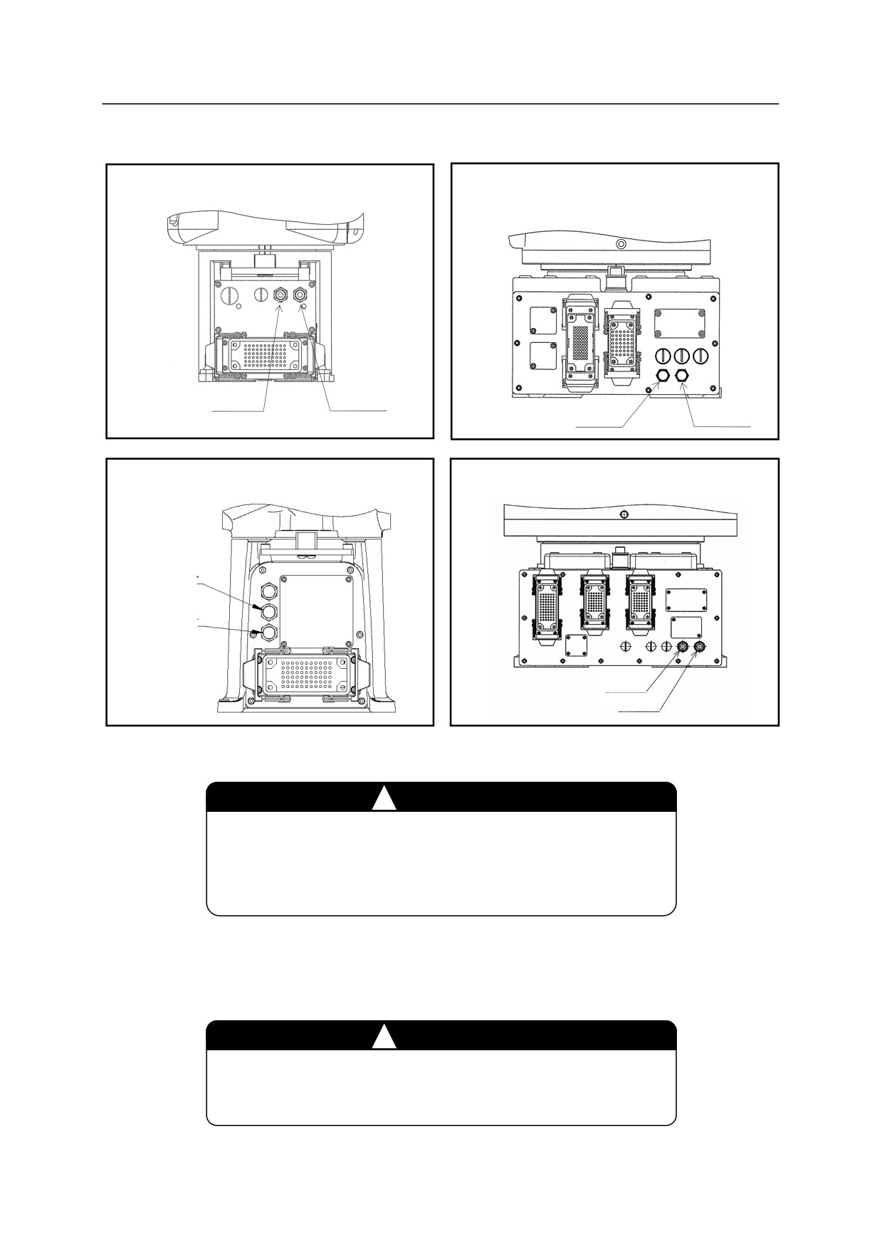
10.2 Air Supply to the Robot Arm
RS05N, RS05L, RA05L, RC05L
RS06L, RS10N, RS10L, RS20N, RA06L,
RA10N, RA10L, RA20N
Port A
Port B
Port A
Port B
RS07N, RS07L
RS15X, RS30N, RS50N, RS80N, RD80N
Port A
Port B
Port A
Port B
As shown above, the air connection port is provided in the base section of robot arm.
㸟
CAUTION
Supply clean dry air with input pressure of 0.15 to 0.6 MPa
(21.7 to 87.0 psi) to the Port A (Rc1/4 for RS05N, RS05L,
RA05L and RC05L and Rc3/8 for the others).
For the air purge specification (except RC05L), Port B is provided with air inlet (Rc1/4 for RS05N,
RS05L and RA05L and Rc3/8 for the others) in the same way as Port A.
㸟
CAUTION
For air purge specification, supply clean dry air with input
pressure of 0.03 MPa (4.35 psi).
53
R Series
10 Connection of Air System
Kawasaki Robot Installation and Connection Manual
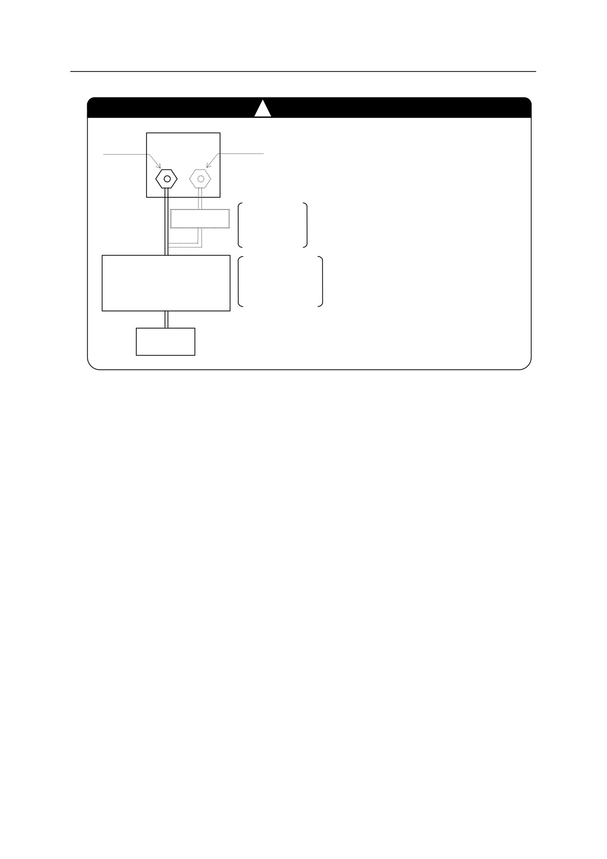
㸟
CAUTION
1. Connect external equipment such as
Port A
Port B
an air dryer, a mist separator and an
air filter when the supplied air
includes water, oil, dust, etc., because
Input pressure
the air supply may lead to
Regulator
0.03 MPa
malfunction or damage on the built-in
(4.35 psi)
valves or the devices inside the arm.
Regulator
Input pressure
In addition, conduct maintenance of
+
0.15 to 0.6 MPa
the connected equipment (draining,
Air dryer/Mist separator/
(21.7 to 87.0 psi)
Air filter
filter cleaning, etc.) periodically.
2. Since built-in valves are non-oiling
Air supply
<Example of external
type, do not use any lubricator (oiler).
source
equipment connection>
54
R Series
10 Connection of Air System
Kawasaki Robot Installation and Connection Manual
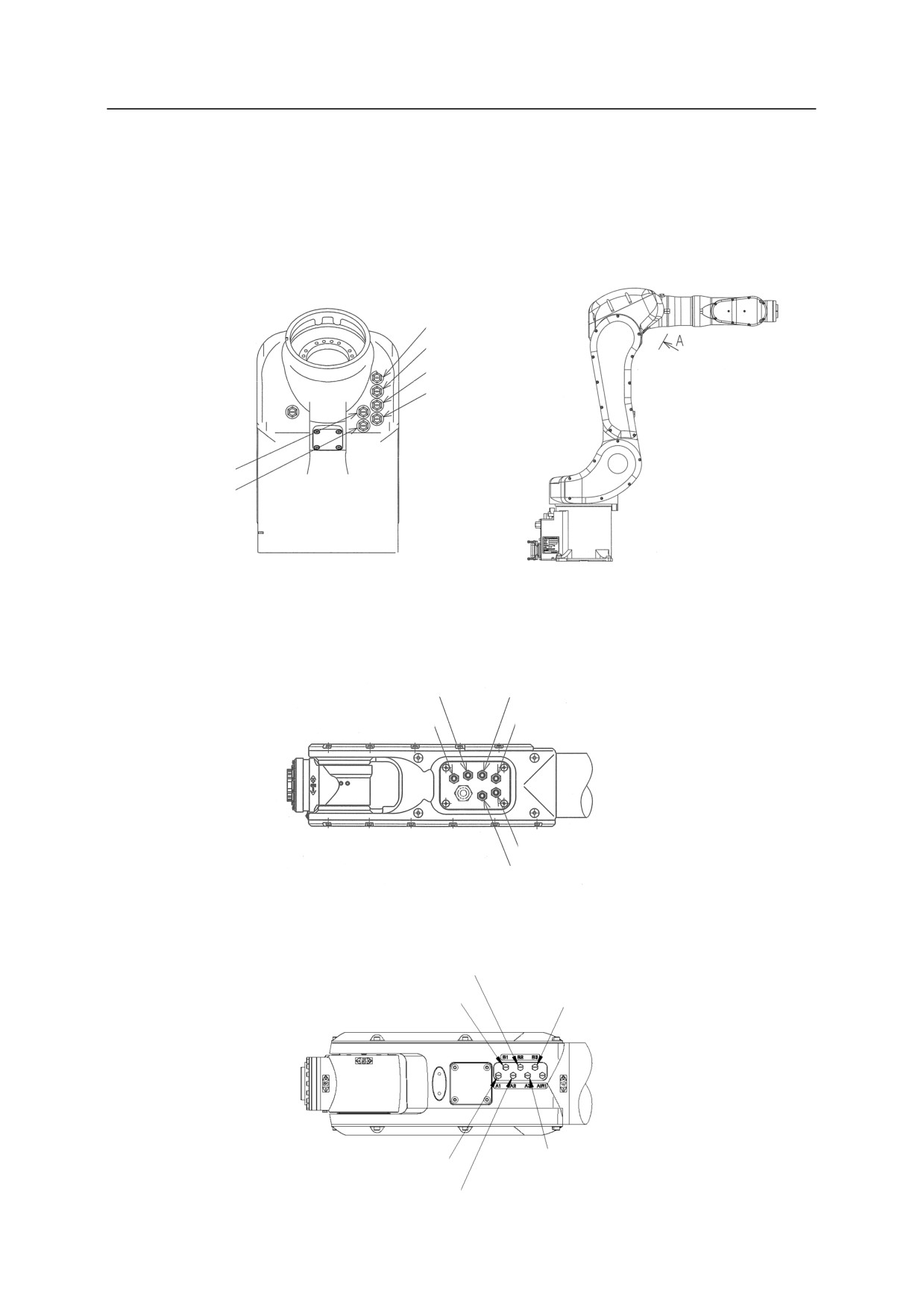
10.3 Tubing from Air Outlet to Tool
As shown in the figure below, air outlet ports are provided (Option). The outlet ports are M5 for RS05N,
RS05L, RA05L and RC05L and Rc1/8 for the others.
RS05N, RS05L, RA05L, RC05L
Port A1
Port B1
Port A2
Port B2
Port A3
Port B3
View A
RS06L, RS10N, RA06L, RA10N
Port B1
Port A2
Port A1
Port B2
Port B3
Port A3
RS07N, RS07L
Port B2
Port B1
Port B3
Port A1
Port A3
Por1t A2
55
R Series
10 Connection of Air System
Kawasaki Robot Installation and Connection Manual
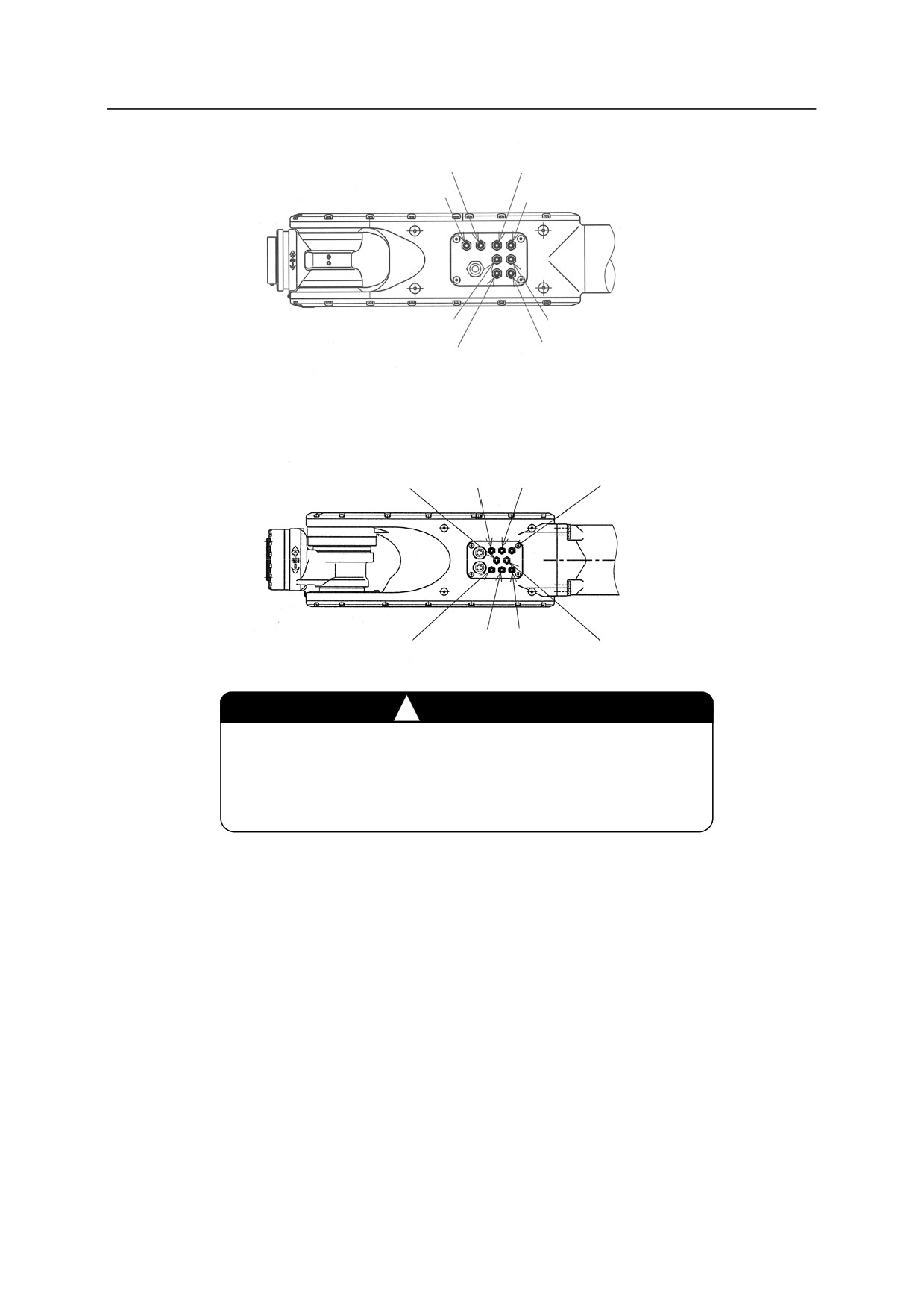
RS10L, RS20N, RA10L, RA20N
Port B1
Port A2
Port A1
Port B2
Port A3
Port B3
Port A4
Port B4
RS15X, RS30N, RS50N, RS80N, RD80N
Port A2
Port A1
Port B1
Port A4
Port A3
Port B3
Port B4
Port B2
㸟
CAUTION
When tubing, ensure that the air outlet ports are not turned.
If the outlet ports turn, the internal tube may bend or break
causing air supply stop at worst.
56