GASGAS EC 450F / EC 500F / EW 500F. OWNER'S MANUAL (2024)

TABLE OF CONTENTS
TABLE OF CONTENTS
1
MEANS OF REPRESENTATION
5
6.18
Foot brake lever
21
6.19
Side stand
21
1.1
Symbols used
5
6.20
Steering lock
21
1.2
Formats used
5
6.21
Locking the steering (All EU models)
22
2
SAFETY ADVICE
6
6.22
Unlocking the steering
22
2.1
Use definition - intended use
6
7
COMBINATION INSTRUMENT
23
2.2
Misuse
6
7.1
Combination instrument overview
23
2.3
Safety advice
6
7.2
Activation
23
2.4
Degrees of risk and symbols
7
7.3
Message on the combination
2.5
Tampering warning
7
instrument
23
2.6
Safe operation
7
7.4
Setting the combination instrument
23
2.7
Protective clothing
8
7.5
Setting kilometers or miles
24
2.8
Work rules
8
7.6
Setting the clock
25
2.9
Environment
8
7.7
Setting the service display
25
2.10
Owner's Manual
9
7.8
Speed, time, and DST distance 1
26
3
IMPORTANT NOTES
10
7.9
Speed, time, and DST2 distance 2
26
7.10
AVG average speed, ART operating
3.1
Manufacturer warranty, implied
hours, and ODO total distance covered
27
warranty
10
3.2
Fuel, auxiliary substances
10
8
PREPARING FOR USE
28
3.3
Spare parts, accessories
10
8.1
Advice on preparing for first use
28
3.4
Service
10
8.2
Running in the engine
29
3.5
Figures
10
8.3
Starting power of lithium-ion batteries
3.6
Customer service
10
at low temperatures
29
8.4
Preparing the vehicle for difficult
4
VIEW OF VEHICLE
11
operating conditions
30
4.1
View of vehicle, front left (example)
11
8.5
Preparing the vehicle for rides on dry
4.2
View of vehicle, rear right (example)
12
sand
30
8.6
Preparing the vehicle for rides on wet
5
SERIAL NUMBERS
13
sand
31
5.1
Vehicle identification number
13
8.7
Preparing the vehicle for rides on wet
5.2
Type label
13
and muddy circuits
31
5.3
Key number
14
8.8
Preparing vehicle for high temperatures
5.4
Engine number
14
or slow riding
32
5.5
Fork part number
14
8.9
Preparing the vehicle for low
5.6
Shock absorber article number
14
temperatures or snow
32
6
CONTROLS
15
9
RIDING INSTRUCTIONS
33
6.1
Clutch lever
15
9.1
Checks and maintenance measures
6.2
Hand brake lever
15
when preparing for use
33
6.3
Throttle grip
15
9.2
Starting the vehicle
33
6.4
Horn button (All EU models)
15
9.3
Activating traction control (optional)
34
6.5
Light switch (All EU models)
16
9.4
Starting off
35
6.6
Light switch (All US models)
16
9.5
Quickshifter (optional)
35
6.7
Turn signal switch (All EU models)
16
9.6
Activating the quickshifter (optional)
35
6.8
Start button
16
9.7
Shifting, riding
36
6.9
Stop button
17
9.8
Braking
36
6.10
Combination switch (optional)
17
9.9
Stopping, parking
37
6.11
Overview of indicator lamps (All EU
9.10
Transporting
37
models)
17
9.11
Refueling
38
6.12
Indicator lamps overview (All US
10
SERVICE SCHEDULE
40
models)
18
6.13
Opening fuel tank filler cap
18
10.1
Additional information
40
6.14
Closing the fuel tank filler cap
19
10.2
Service schedule
40
6.15
Cold start button
19
6.16
Idle speed adjusting screw
20
6.17
Shift lever
20
2

TABLE OF CONTENTS
11
TUNING THE CHASSIS
42
12.27
Preparing air filter box cover for
securing
66
11.1
Checking the basic chassis setting with
12.28
Removing the main silencer
66
the rider's weight
42
12.29
Installing the main silencer
67
11.2
Compression damping of the shock
12.30
Cleaning spark arrestor (EW 500F US)....
67
absorber
42
12.31
Changing the glass fiber yarn filling in
11.3
Adjusting the low-speed compression
the main silencer
69
damping of the shock absorber
42
12.32
Removing the fuel tank
70
11.4
Adjusting the high-speed compression
12.33
Installing the fuel tank
71
damping of the shock absorber
43
12.34
Checking for chain dirt accumulation
73
11.5
Adjusting the rebound damping of the
12.35
Cleaning the chain
73
shock absorber
43
12.36
Checking the chain tension
74
11.6
Measuring the dimension of the rear
12.37
Adjusting the chain tension
74
wheel unloaded
44
11.7
Checking the static sag of the shock
12.38
Checking the chain, rear sprocket,
engine sprocket, and chain guide
75
absorber
44
12.39
Checking the frame
78
11.8
Checking the rider sag of the shock
absorber
45
12.40
Checking the link fork
78
11.9
Adjusting the spring preload of the
12.41
Checking the throttle cable routing
78
shock absorber
45
12.42
Checking the rubber grip
79
11.10
Adjusting the rider sag
46
12.43
Programming the Quickshifter
11.11
Checking the basic setting of the fork
47
(optional)
80
11.12
Adjusting the compression damping of
12.44
Adjusting the basic position of the clutch
the fork
47
lever
80
11.13
Adjusting the rebound damping of the
12.45
Checking/correcting the fluid level of
fork
48
hydraulic clutch
81
11.14
Handlebar position
48
12.46
Changing the hydraulic clutch fluid
82
11.15
Adjusting the handlebar position
49
13
BRAKE SYSTEM
84
12
SERVICE WORK ON THE CHASSIS
50
13.1
Adjusting the basic position of the hand
12.1
Raising the motorcycle with a lift stand
50
brake lever
84
13.2
Checking the brake discs
84
12.2
Removing the motorcycle from the lift
stand
50
13.3
Checking the front brake fluid level
84
12.3
Bleeding the fork legs
50
13.4
Adding front brake fluid
85
12.4
Cleaning the dust boots of the fork legs
51
13.5
Checking that the brake linings of the
front brake are secured
86
12.5
Removing the fork protector
51
13.6
Changing the brake linings of the front
12.6
Installing the fork protector
52
brake
87
12.7
Removing the fork legs
52
13.7
Checking the free travel of foot brake
12.8
Installing the fork legs
53
lever
89
12.9
Removing the frame protector
53
13.8
Adjusting the basic position of the foot
12.10
Installing the frame protector
54
brake lever
89
12.11
Removing the lower triple clamp
54
13.9
Checking the rear brake fluid level
90
12.12
Installing the lower triple clamp
55
13.10
Adding rear brake fluid
91
12.13
Checking the steering head bearing play ... 57
13.11
Checking that the brake linings of the
12.14
Adjusting the steering head bearing
rear brake are secured
92
play
57
13.12
Changing the rear brake linings
92
12.15
Lubricating the steering head bearing
58
12.16
Removing the front fender
58
14
WHEELS, TIRES
95
12.17
Installing the front fender
59
14.1
Removing the front wheel
95
12.18
Removing the shock absorber
59
14.2
Installing the front wheel
96
12.19
Installing the shock absorber
60
14.3
Removing the rear wheel
96
12.20
Removing the seat
62
14.4
Installing the rear wheel
97
12.21
Mounting the seat
62
14.5
Checking the tire condition
99
12.22
Removing the air filter box cover
63
14.6
Checking tire pressure
99
12.23
Installing the air filter box cover
64
14.7
Checking spoke tension
100
12.24
Removing the air filter
64
12.25
Installing the air filter
65
15
ELECTRICAL SYSTEM
101
12.26
Cleaning the air filter and air filter
15.1
Removing the 12-V battery
101
box
65
3

TABLE OF CONTENTS
15.2
Installing the 12-V battery
102
22
BLINK CODE
132
15.3
Charging the 12-V battery
102
23
TECHNICAL SPECIFICATIONS
134
15.4
Changing the main fuse
104
15.5
Removing the headlight mask with the
23.1
Engine
134
headlight
105
23.2
Engine tightening torques
135
15.6
Installing the headlight mask with the
23.3
Capacities
136
headlight
106
23.3.1
Engine oil
136
15.7
Changing the headlight bulb
107
23.3.2
Coolant
136
15.8
Checking the headlight setting
107
23.3.3
Fuel
136
15.9
Adjusting the headlight range
108
23.4
Chassis
136
15.10
Changing the turn signal bulb (All EU
23.5
Electrical system
137
models)
108
23.6
Tires
138
15.11
Changing the combination instrument
23.7
Fork
138
battery
109
23.8
Shock absorber
138
15.12
Diagnostics connector
110
23.9
Chassis tightening torques
139
15.13
OCU
110
24
SUBSTANCES
142
16
COOLING SYSTEM
111
25
AUXILIARY SUBSTANCES
144
16.1
Cooling system
111
26
STANDARDS
146
16.2
Checking the antifreeze and coolant
level
111
27
INDEX OF SPECIAL TERMS
147
16.3
Checking the coolant level
112
28
LIST OF ABBREVIATIONS
148
16.4
Draining the coolant
112
16.5
Refilling coolant
113
29
LIST OF SYMBOLS
149
16.6
Changing the coolant
114
29.1
Yellow and orange symbols
149
17
TUNING THE ENGINE
115
29.2
Green and blue symbols
149
17.1
Checking the play in the throttle cable....
115
INDEX
150
17.2
Adjusting the play in the throttle
cable
115
17.3
Adjusting the characteristic map of the
throttle response
116
17.4
Changing the mapping (optional)
117
17.5
Adjusting the idle speed
118
17.6
Programming the throttle valve
position
119
17.7
Checking the basic position of the shift
lever
119
17.8
Adjusting the basic position of the shift
lever
120
18
SERVICE WORK ON THE ENGINE
121
18.1
Changing the fuel screen
121
18.2
Checking the engine oil level
122
18.3
Changing the engine oil and oil filter,
cleaning the oil screen
122
18.4
Adding engine oil
125
19
CLEANING, CARE
126
19.1
Cleaning the motorcycle
126
19.2
Checks and maintenance steps for
winter operation
127
20
STORAGE
128
20.1
Storage
128
20.2
Preparing for use after storage
129
21
TROUBLESHOOTING
130
4

MEANS OF REPRESENTATION
1
1.1
Symbols used
The meaning of specific symbols is described below.
Indicates an expected reaction (e.g., of a work step or a function).
Indicates an unexpected reaction (e.g., of a work step or a function).
Indicates work that requires expert knowledge and technical understanding. In the interest of your own
safety, have this work performed by an authorized GASGAS Motorcycles workshop. Your motorcycle will
be cared for there to the highest degree by specially trained experts using the special tools required.
Indicates a page reference (more information is provided on the specified page).
Indicates information with more details or tips.
Indicates the result of a testing step.
Indicates the end of an activity, including potential reworking.
1.2
Formats used
The typographical formats used in this document are explained below.
Proprietary name
Indicates a proprietary name.
Name®
Indicates a protected name.
Brand™
Indicates a brand available on the open market.
Underlined terms
Refer to technical details of the vehicle or indicate technical terms, which are
explained in the glossary.
5

2
SAFETY ADVICE
2.1
Use definition - intended use
(All EU models)
This vehicle has been designed and built to withstand the normal stresses and strains of racing. This vehicle complies
with the currently valid regulations and categories of the top international motorsports organizations.
Info
This vehicle is only authorized for operation on public roads in the homologated (restricted) version.
The derestricted version of this vehicle must only be operated in closed off areas away from public highway
traffic.
This vehicle is designed for use in offroad endurance competition, and not primarily for use in motocross.
(EC 450F US)
This vehicle has been designed and built to withstand the normal stresses and strains of offroad leisure use.
Info
This vehicle is homologated and approved for use on public roads.
No homologation-relevant components may be removed or modified.
(EW 500F US)
This vehicle has been designed and built to withstand the normal stresses and strains of offroad leisure use. Addition-
ally, it fulfills the CARB (California Air Resources Board) guidelines of the Green Sticker program.
Info
This vehicle is not approved for use on public roads.
No homologation-relevant components may be removed or modified.
This vehicle is not designed for use in racing on closed circuits or for Motocross use.
2.2
Misuse
The vehicle must only be used as intended.
Dangers can arise for people, property and the environment through use not as intended.
Any use of the vehicle beyond the intended and defined use constitutes misuse.
Misuse also includes the use of operating and auxiliary fluids which do not meet the required specification for the respec-
tive use.
2.3
Safety advice
A number of safety instructions need to be followed to operate the product described safely. Therefore read this instruction
and all further instructions included carefully. The safety instructions are highlighted in the text and are referred to at the
relevant passages.
Info
Various information and warning labels are attached in prominent locations on the product described. Do not
remove any information or warning labels. If they are missing, you or others may not recognize dangers and may
therefore be injured.
6

SAFETY ADVICE
2
2.4
Degrees of risk and symbols
Danger
Identifies a danger that will immediately and invariably lead to fatal or serious permanent injury if the appropriate
measures are not taken.
Warning
Identifies a danger that is likely to lead to fatal or serious injury if the appropriate measures are not taken.
Caution
Identifies a danger that may lead to minor injuries if the appropriate measures are not taken.
Note
Identifies a danger that will lead to considerable machine and material damage if the appropriate measures are not taken.
Note
Indicates a danger that will lead to environmental damage if the appropriate measures are not taken.
2.5
Tampering warning
Tampering with the noise control system is prohibited. Federal law prohibits the following acts or the causing thereof:
1
The removal or rendering inoperative by any person other than for purposes of servicing, repair, or replacement, of
any device or element of design incorporated into any new vehicle for the purpose of noise control prior to its sale or
delivery to the ultimate purchaser or while it is in use, or
2
the use of the vehicle after such device or element of design has been removed or rendered inoperative by any person.
Among those acts presumed to constitute tampering are the acts listed below:
1
Removal or puncturing of the main silencers, baffles, manifolds or any other components which conduct emissions.
2
Removal or puncturing of parts of the intake system.
3
Lack of proper maintenance.
4
Replacing moving parts of the vehicle, or parts of the exhaust system or intake system, with parts other than those
specified by the manufacturer.
(EW 500F US)
An add-on or modified part must be compliant with applicable ARB evaporative emission control standards. A violation
of this requirement is punishable by civil and/or criminal punishment.
2.6
Safe operation
Danger
Danger of accidents A rider who is not fit to ride poses a danger to him or herself and others.
- Do not operate the vehicle if you are not fit to ride due to alcohol, drugs or medication.
- Do not operate the vehicle if you are physically or mentally impaired.
Danger
Danger of poisoning Exhaust gases are toxic and inhaling them may result in unconsciousness and death.
- Always make sure there is sufficient ventilation when running the engine.
- Use effective exhaust extraction when starting or running the engine in an enclosed space.
7

2
SAFETY ADVICE
Warning
Danger of burns Some vehicle components become hot when the vehicle is operated.
- Do not touch any parts such as the exhaust system, radiator, engine, damper, or brake system before the vehi-
cle parts have cooled down.
- Let the vehicle parts cool down before you perform any work on the vehicle.
Only operate the vehicle when it is in perfect technical condition, in accordance with its intended use, and in a safe and
environmentally compatible manner.
An appropriate driver's license is needed to drive the vehicle on public roads.
Have malfunctions that impair safety immediately eliminated by an authorized GASGAS Motorcycles workshop.
Adhere to the information and warning labels on the vehicle.
2.7
Protective clothing
Warning
Risk of injury Missing or poor protective clothing presents an increased safety risk.
- Wear appropriate protective clothing such as helmet, boots, gloves as well as trousers and a jacket with pro-
tectors on all rides.
- Always wear protective clothing that is in good condition and meets the legal regulations.
In the interest of your own safety, GASGAS Motorcycles recommends that you only operate the vehicle while wearing pro-
tective clothing.
2.8
Work rules
Unless specified otherwise, the ignition must be turned off during all work (models with ignition lock, models with transpon-
der key) or the motor must be at a standstill (models without ignition lock or transponder key).
Special tools are necessary for certain tasks. The tools are not a component of the vehicle, but can be ordered using the
number in parentheses. Example: bearing puller (15112017000)
Unless otherwise noted, normal conditions apply to all tasks and descriptions.
Ambient temperature
20 °C (68 °F)
Ambient air pressure
1,013 mbar (14.69 psi)
Relative air humidity
60 ± 5 %
During assembly, use new parts to replace parts which cannot be reused (e.g. self-locking screws and nuts, expansion
screws, seals, sealing rings, O-rings, pins, and lock washers).
In the case of certain screws, a screw adhesive (e.g. Loctite®) is required. Observe the manufacturer's instructions.
If thread locker (e.g., Precote®) has already been applied to a new part, do not apply any additional thread locker.
After disassembly, clean the parts that are to be reused and check them for damage and wear. Change damaged or worn
parts.
After completing a repair or service work, check the operating safety of the vehicle.
2.9
Environment
If you use your motorcycle responsibly, you can ensure that problems and conflicts do not occur. To protect the future of
the motorcycle sport, make sure that you use your motorcycle legally, be environmentally aware, and respect the rights of
others.
When disposing of used oil, other operating and auxiliary fluids, and used components, comply with the laws and regula-
tions of the respective country.
Because motorcycles are not subject to the EU regulations governing the disposal of used vehicles, there are no legal regu-
lations that pertain to the disposal of an end-of-life motorcycle. Your authorized GASGAS Motorcycles dealer will be glad to
advise you.
8

SAFETY ADVICE
2
2.10
Owner's Manual
Read this owner's manual carefully and completely before making your first trip. The Owner's Manual contains useful infor-
mation and many tips on how to operate, handle, and service your motorcycle. This is the only way to find out how best to
customize the vehicle for your own use and how you can protect yourself from injury.
Tip
Store the Owner's Manual on your terminal device, for example, so that you can read it whenever you need to.
If you would like to know more about the vehicle or have questions on the material you read, please contact an authorized
GASGAS Motorcycles dealer.
The Owner's Manual is an important component of the vehicle. If the vehicle is sold, the Owner's Manual must be down-
loaded again by the new owner.
The Owner's Manual can be downloaded several times using the QR code or the link on the delivery certificate.
The Owner's Manual is available for download from your authorized GASGAS Motorcycles dealer and on the
GASGAS Motorcycles website.
International GASGAS Motorcycles website: http://www.gasgas.com
9

3
IMPORTANT NOTES
3.1
Manufacturer warranty, implied warranty
The work specified in the service schedule may only be carried out in an authorized GASGAS Motorcycles workshop and
confirmed in the GASGAS Motorcycles Dealer.net, as otherwise all warranty claims will be void. Damage or secondary dam-
age caused by tampering with and/or conversions on the vehicle are not covered by the manufacturer warranty.
3.2
Fuel, auxiliary substances
Note
Environmental hazard Improper handling of fuel is a danger to the environment.
- Do not allow fuel to enter the groundwater, the soil, or the sewage system.
Use fuels and auxiliary substances in accordance with the Owner's Manual and specification.
3.3
Spare parts, accessories
For your own safety, only use spare parts and accessory products that are approved and/or recommended by
GASGAS Motorcycles and have them installed by an authorized GASGAS Motorcycles workshop. GASGAS Motorcycles
accepts no liability for other products and any resulting damage or loss.
Certain spare parts and accessory products are specified in parentheses in the descriptions. Your authorized
GASGAS Motorcycles dealer will be glad to advise you.
The latest news GASGAS Technical Accessories on your vehicle can be found on the GASGAS Motorcycles website.
International GASGAS Motorcycles website: http://www.gasgas.com
3.4
Service
A prerequisite for perfect operation and prevention of premature wear is that the service, care, and tuning work on the
engine and chassis is properly carried out as described in the Owner's Manual. An incorrect suspension setting can lead to
damage and breakage of chassis components.
Use of the vehicle under difficult conditions, such as on sand or on wet, dusty and muddy surfaces, can result in significantly
increased wear of components, such as the drive train, brake system, air filter or suspension components. For this reason, it
may be necessary to inspect or replace parts before the next scheduled service.
It is imperative that you adhere to the stipulated run-in times and service intervals. If you observe these exactly, you will
ensure a much longer service life for your motorcycle.
The relevant mileage or time interval is whichever occurs first.
3.5
Figures
The figures contained in the manual may depict special equipment.
In the interest of clarity, some components may be shown disassembled or may not be shown at all. It is not always neces-
sary to disassemble the component to perform the activity in question. Please follow the instructions in the text.
3.6
Customer service
Your authorized GASGAS Motorcycles dealer will be happy to answer any questions you may have regarding your vehicle
and GASGAS Motorcycles.
A list of authorized GASGAS Motorcycles dealers can be found on the GASGAS Motorcycles website.
International GASGAS Motorcycles website: http://www.gasgas.com
10
VIEW OF VEHICLE
4
4.1
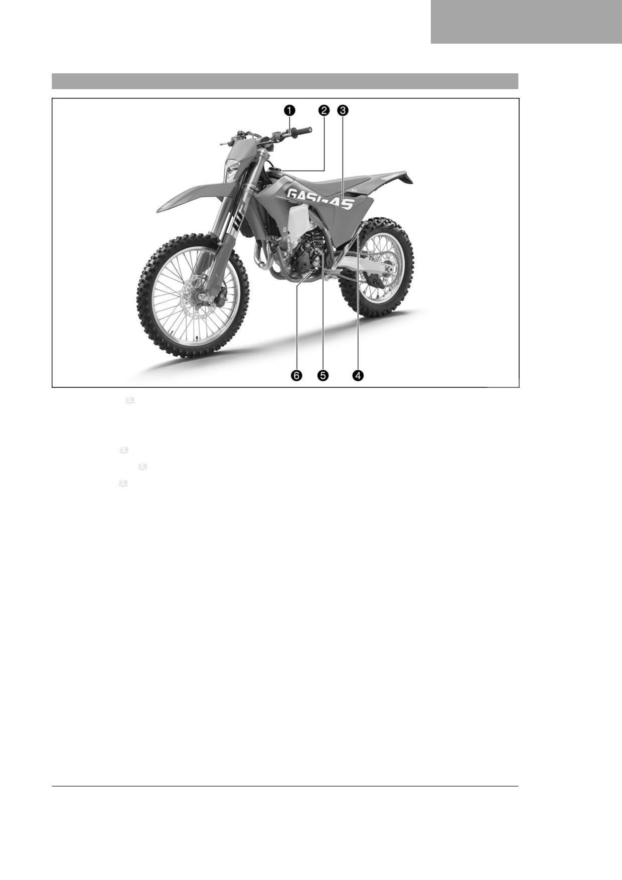
View of vehicle, front left (example)
A01312-01
1 Clutch lever ( p. 15)
2 Fuel tank filler cap
3 Air filter box cover
4 Side stand ( p. 21)
5 Engine number ( p. 14)
6 Shift lever ( p. 20)
11
4
VIEW OF VEHICLE
4.2
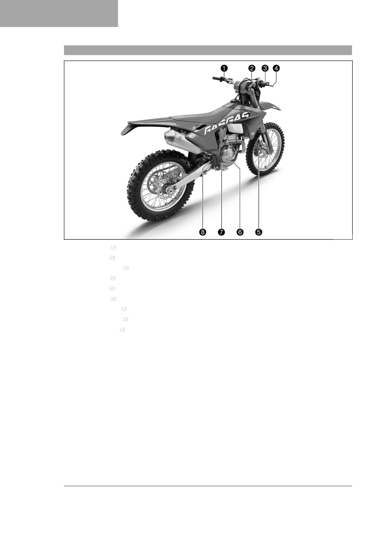
View of vehicle, rear right (example)
A01381-10
1 Horn button ( p. 15) (All EU models)
1 Light switch ( p. 16) (All EU models)
1 Turn signal switch ( p. 16) (All EU models)
2 Start button ( p. 16)
2 Stop button ( p. 17)
3 Throttle grip ( p. 15)
4 Hand brake lever ( p. 15)
5 Fork part number ( p. 14)
6 Foot brake lever ( p. 21)
7 Level viewer, engine oil
8 Level viewer for brake fluid, rear
12
SERIAL NUMBERS
5
5.1
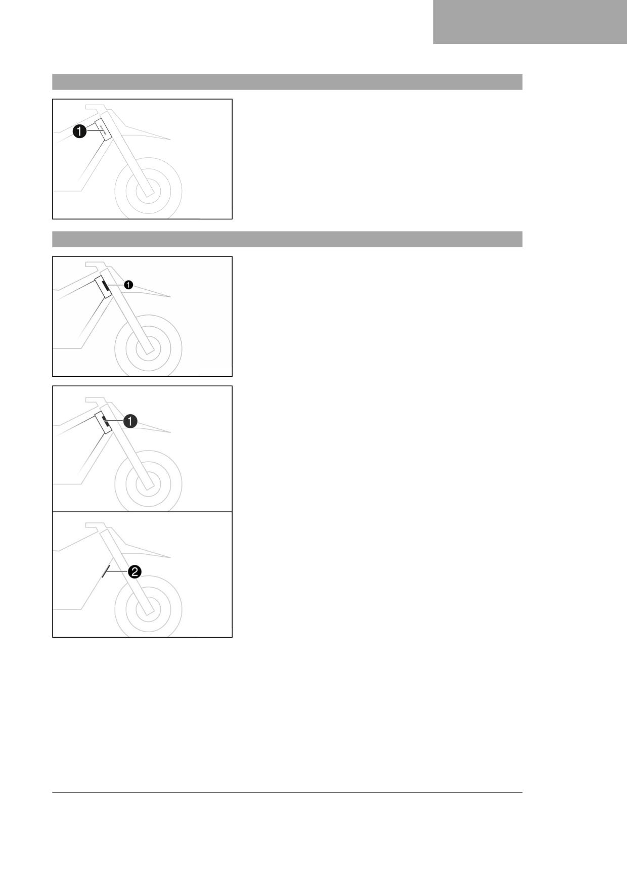
Vehicle identification number
The vehicle identification number 1 is stamped on the right side of the
steering head.
401945-10
5.2
Type label
(All EU models)
The Europe type label 1 is fixed to the front of the steering head.
T04627-01
(All US models)
The type label USA 1 is fixed to the front of the chest tube.
The type label Canada 2 is fixed to the front of the chest tube.
M00994-10
13
5
SERIAL NUMBERS
5.3
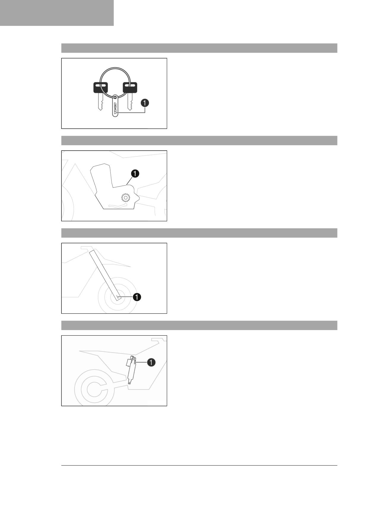
Key number
Key number 1 for the steering lock is stamped on a tag on the key
ring.
H02475-10
5.4
Engine number
The engine number 1 is embossed on the left side of the engine over
the engine sprocket.
H01047-10
5.5
Fork part number
The fork part number 1 is stamped on the inner side of the fork stub.
401947-10
5.6
Shock absorber article number
Shock absorber article number 1 is stamped on the top of the shock
absorber above the adjusting ring towards the engine side.
H02222-10
14
CONTROLS
6
6.1
Clutch lever
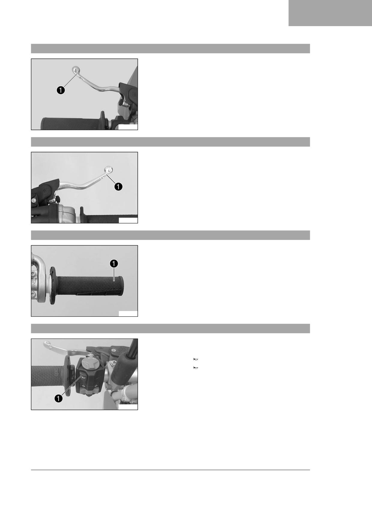
Clutch lever 1 is fitted on the handlebar on the left.
The clutch is activated hydraulically and adjusts itself automatically.
A01314-10
6.2
Hand brake lever
The hand brake lever 1 is fitted on the right side of the handlebar.
The hand brake lever is used to activate the front brake.
F03161-10
6.3
Throttle grip
The throttle grip 1 is fitted on the right side of the handlebar.
F03162-10
6.4
Horn button (All EU models)
Horn button 1 is fitted on the left side of the handlebar.
Possible states
• The horn button is in the basic position
• The horn button is pressed - The horn is operated in this posi-
tion.
A01316-10
15
6
CONTROLS
6.5
Light switch (All EU models)
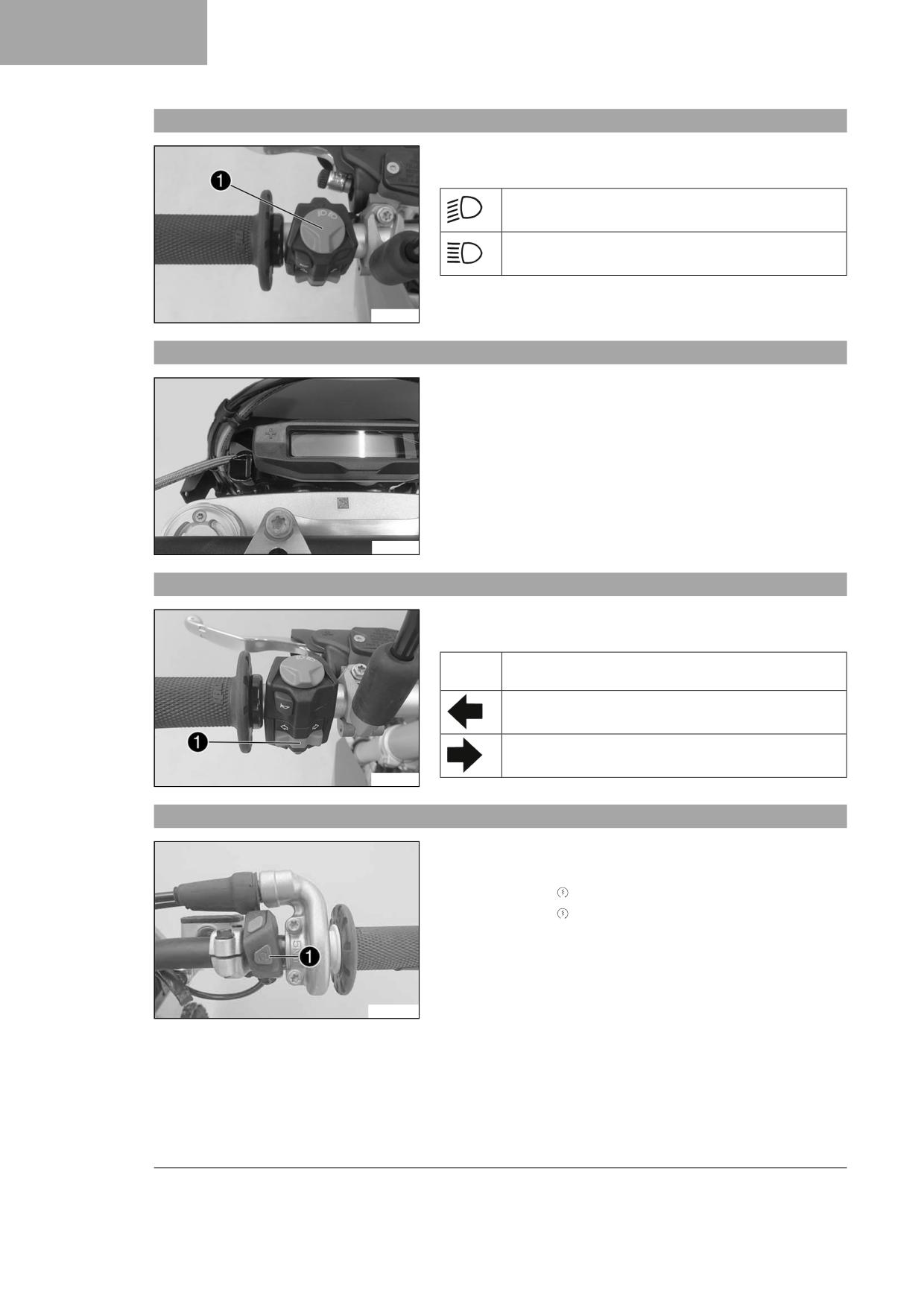
Light switch 1 is fitted on the left side of the handlebar.
Possible states
Low beam on - Light switch is in the central position. In
this position, the low beam and tail light are switched on.
High beam on - Light switch is turned to the left. In this
position, the high beam and the tail light are switched on.
A01315-10
6.6
Light switch (All US models)
The button 1 is located to the left of the combination instrument.
Possible states
• Light off - Button is in the basic position, the light is switched off.
• Light on - Button is pressed in until it engages. Low beam and tail
light are switched on.
T04626-01
6.7
Turn signal switch (All EU models)
Turn signal switch 1 is fitted on the left side of the handlebar.
Possible states
Turn signal off - The turn signal switch is in the central
position.
Left turn signal, on - The turn signal switch is turned to the
left.
Right turn signal, on - The turn signal switch is turned to
the right.
A01317-10
6.8
Start button
Start button 1 is fitted on the right side of the handlebar.
Possible states
• The start button is in the basic position
• The start button is pressed - The starter motor is actuated in this
position.
W00296-11
16
CONTROLS
6
6.9
Stop button
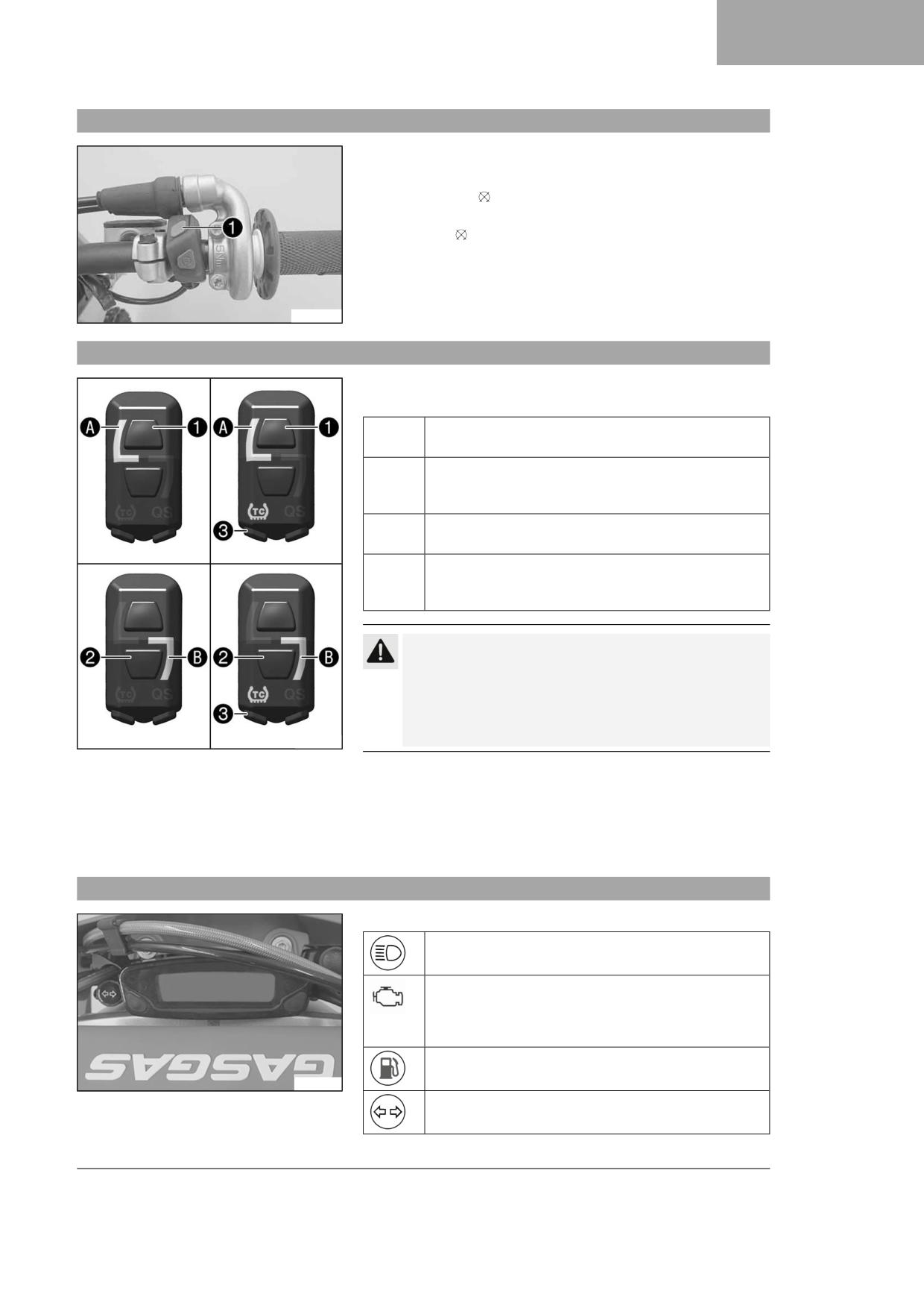
The stop button 1 is located on the right side of the handlebar.
Possible states
• The stop button is in the basic position - In this position, the
ignition circuit is closed and the engine can be started.
• Stop button pressed - In this position, the ignition circuit is inter-
rupted, a running engine stops, and a non-running engine will not
start.
W00296-10
6.10
Combination switch (optional)
The combination switch is fitted on the left side of the handlebar.
Possible states
1
STANDARD - STANDARD mapping is activated when the
indicator lamp A lights up.
1 TC
STANDARD with TC - STANDARD mapping with traction
control is activated when the indicator lamp A and the
TC indicator lamp light up.
2
ADVANCED - ADVANCED mapping is activated when the
indicator lamp B lights up.
2 TC
ADVANCED with TC - ADVANCED mapping with traction
control is activated when the indicator lamp B and the
TC indicator lamp light up.
Caution
Voiding of the government approval for road use and the
insurance coverage If the combination switch is mounted,
the vehicle’s road permit, if any, expires.
- Only operate the vehicle in closed-off areas remote from
public road traffic if the combination switch is installed.
F03761-10
The engine characteristic can be changed using button 1 and but-
ton 2 on the combination switch.
Traction control can be activated using the TC button 3 on the combi-
nation switch.
The quick shifter can also be activated via the combination switch.
6.11
Overview of indicator lamps (All EU models)
Possible states
The high beam indicator lamp lights up blue - The high
beam is switched on.
Malfunction indicator lamp lights up/flashes yellow - The
OBD has detected an error in the vehicle electronics. Come
safely to a halt, and contact an authorized GASGAS Motor-
cycles dealer.
The fuel level warning lamp lights up yellow - The fuel level
has reached the reserve mark.
A01319-10
Turn signal indicator lamp flashes green - The turn signal is
switched on.
17
6
CONTROLS
6.12
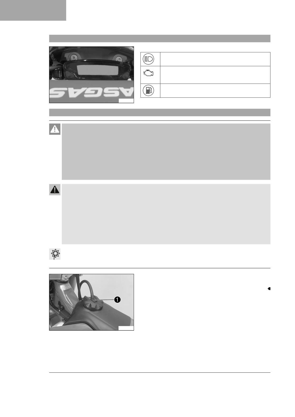
Indicator lamps overview (All US models)
Possible states
The high beam indicator lamp lights up blue - The high
beam is switched on.
Malfunction indicator lamp lights up/flashes yellow - The
OBD has detected an error in the vehicle electronics. Come
safely to a halt, and contact an authorized KTM workshop.
The fuel level warning lamp lights up yellow - The fuel level
has reached the reserve mark.
T04628-01
6.13
Opening fuel tank filler cap
Danger
Fire hazard Fuel is highly flammable.
The fuel in the fuel tank expands when warm and can escape if overfilled.
- Do not fuel the vehicle in the vicinity of open flames or lit cigarettes.
- Switch off the engine for refueling.
- Make sure that no fuel is spilled; particularly not on hot parts of the vehicle.
- If any fuel is spilled, wipe it off immediately.
- Observe the specifications for refueling.
Warning
Danger of poisoning Fuel is harmful to health.
- Avoid skin, eye and clothing contact with fuel.
- Immediately consult a doctor if you swallow fuel.
- Do not inhale fuel vapors.
- Rinse the affected area immediately with plenty of water in the event of contact with the skin.
- Rinse the eyes thoroughly with water, and consult a doctor in case of fuel contact with the eyes.
- Change your clothing if fuel spills on them.
- Keep fuels correctly in a suitable canister, and out of the reach of children.
Note
Environmental hazard Improper handling of fuel is a danger to the environment.
- Do not allow fuel to enter the groundwater, the soil, or the sewage system.
- Press release button 1, turn the fuel tank filler cap counterclock-
wise, and lift it off.
A01320-20
18
CONTROLS
6
6.14
Closing the fuel tank filler cap
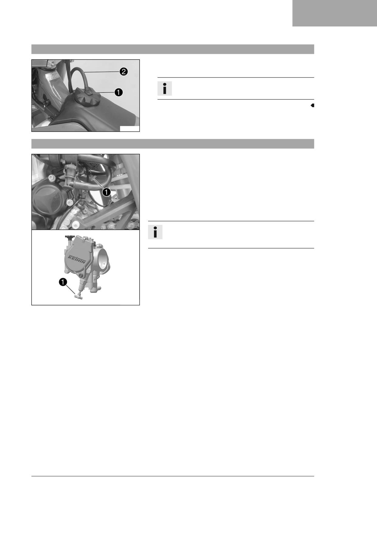
- Mount fuel tank filler cap and turn it clockwise until the release but-
ton 1 engages.
Info
Route fuel tank breather hose 2 without kinks.
A01320-10
6.15
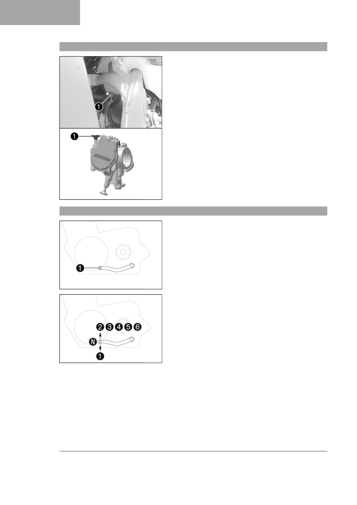
Cold start button
The cold start button 1 is fitted to the bottom of the throttle valve
body.
The electronic fuel injection system extends the injection time if the
engine is cold and the ambient temperature is low. To help the engine
burn the increased fuel quantity, it must be supplied with additional
oxygen by pushing the cold start button.
After briefly opening up the throttle and then releasing the throttle grip
again, or turning the throttle grip towards the front, the cold start but-
ton returns to its original position.
Info
Check whether the cold start button has returned to its basic
position.
Possible states
• The cold start button is activated - The cold start button is pushed
in all the way.
• The cold start button is deactivated - The cold start button is in its
basic position.
A01321-10
19
6
CONTROLS
6.16
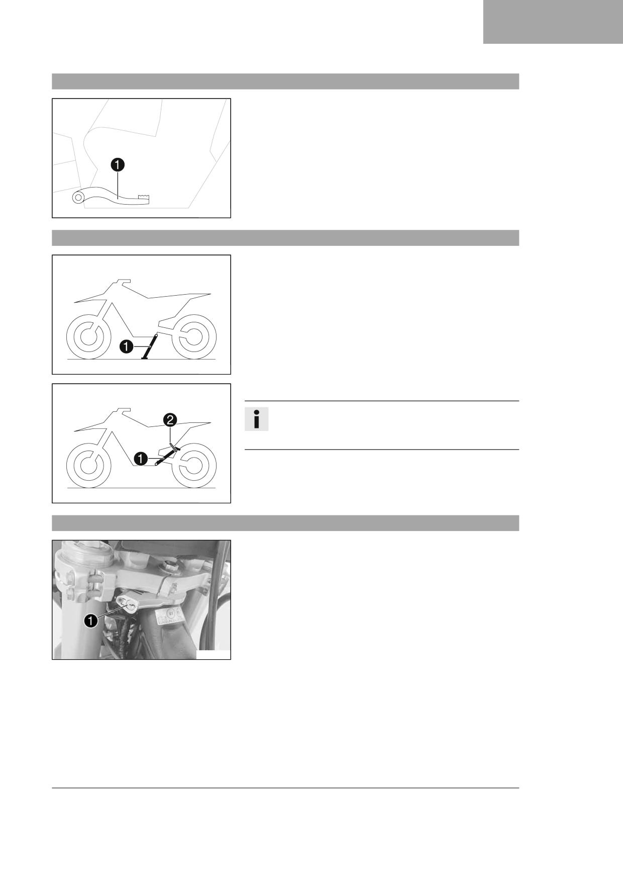
Idle speed adjusting screw
The idle setting of the throttle valve body substantially influences
the vehicle’s starting behavior, a stable idle speed, and the vehicle’s
response when the throttle is opened.
An engine with a correctly set idle speed is easier to start than an engine
with the idle speed set incorrectly.
The idle speed is adjusted using the idle speed adjusting screw 1.
Increase the idle speed by turning the idle speed adjusting screw clock-
wise.
Decrease the idle speed by turning the idle speed adjusting screw coun-
terclockwise.
R06539-10
6.17
Shift lever
Shift lever 1 is mounted on the left of the engine.
401950-10
The gear positions can be seen in the figure.
The neutral or idle position is between the first and second gears.
401950-11
20
CONTROLS
6
6.18
Foot brake lever
Foot brake lever 1 is located in front of the right footrest.
The rear brake is engaged with the foot brake lever.
401956-10
6.19
Side stand
The side stand 1 is attached to the left side of the vehicle.
401943-10
The side stand is used for parking the motorcycle.
Info
When you are riding, side stand 1 must be folded up and
secured with rubber strap 2.
401944-10
6.20
Steering lock
Steering lock 1 is fitted on the left side of the steering head.
The steering lock is used to lock the steering. Steering, and therefore
riding, is no longer possible.
W00352-10
21

6
CONTROLS
6.21
Locking the steering (All EU models)
Note
Danger of damage The parked vehicle can roll away or fall over.
- Park the vehicle on a firm and level surface.
- Park the vehicle.
- Turn handlebar as far as possible to the right.
- Lubricate the steering lock regularly.
Universal oil spray ( p. 145)
- Insert the key for the steering lock into the steering lock ( p. 21),
turn it to the left, push it in, and turn it to the right. Pull out the key
for the steering lock.
Steering is no longer possible.
400732-01
Info
Never leave the key for the steering lock in the steering lock.
6.22
Unlocking the steering
- Insert the key for the steering lock into thesteering lock ( p. 21),
turn it to the left, pull it out, pull it out, and turn it to the right. Pull
out the key for the steering lock.
The handlebar can now be moved again.
Info
Never leave the key for the steering lock in the steering lock.
400731-01
22
COMBINATION INSTRUMENT
7
7.1
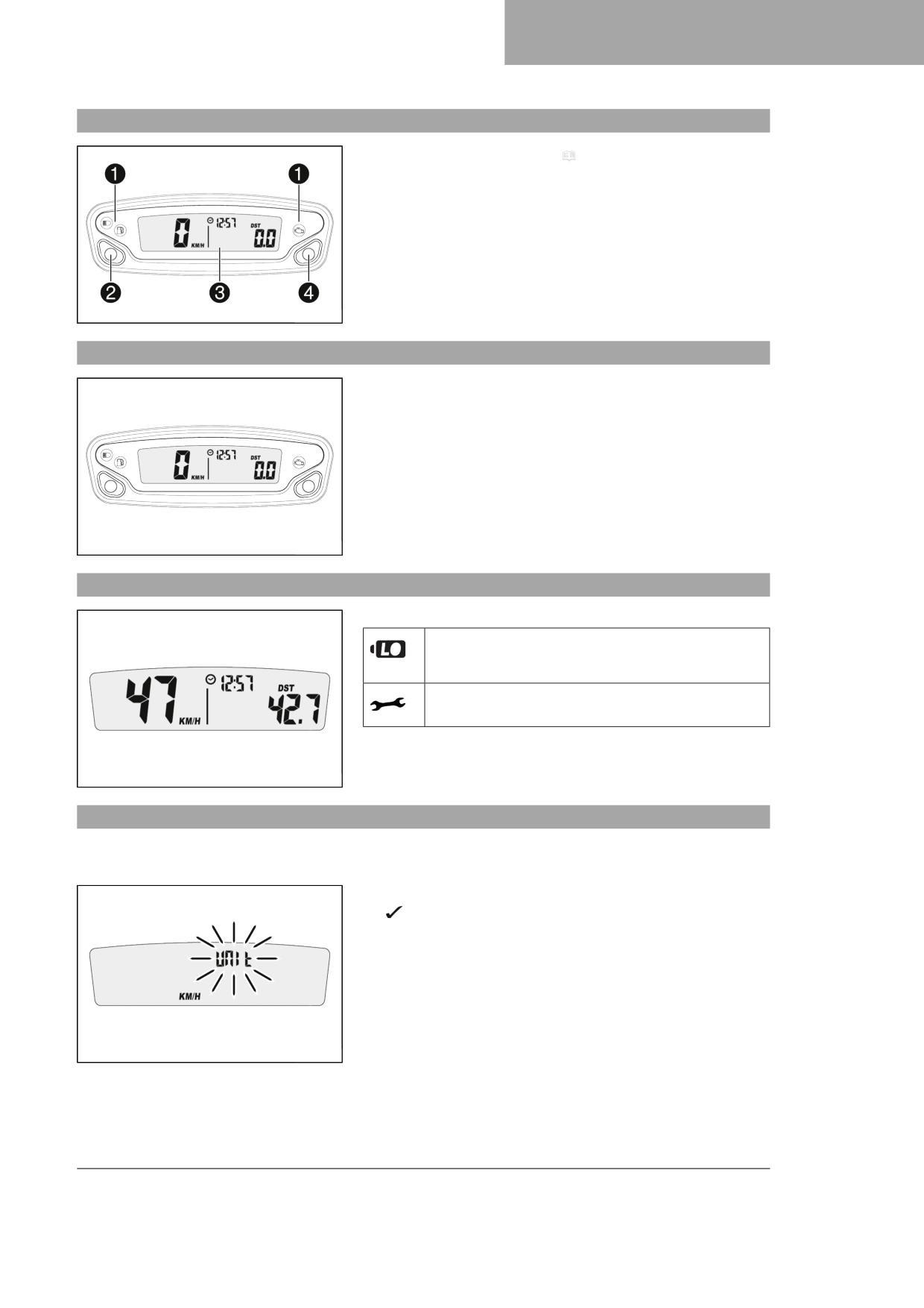
Combination instrument overview
1 Overview of indicator lamps ( p. 17) (All EU models)
2 Left button
3 Display
4 Right button
402819-10
7.2
Activation
Activating combination instrument
The combination instrument is activated when one of the buttons is
pressed or an impulse comes from the wheel speed sensor.
402819-01
7.3
Message on the combination instrument
Possible states
Battery voltage of the combination instrument - Battery
voltage of the combination instrument is too low. Change
combination instrument battery.
Service - A service is due. Contact an authorized GAS-
GAS Motorcycles workshop.
401901-01
7.4
Setting the combination instrument
Condition
The motorcycle is stationary.
- Press and hold both buttons for 3 - 5 seconds.
The Setup menu is displayed. The UNIT display flashes.
- Press one of the buttons to select UNIT for the speed in kilometers
KM/H or miles M/H.
401909-01
23
7
COMBINATION INSTRUMENT
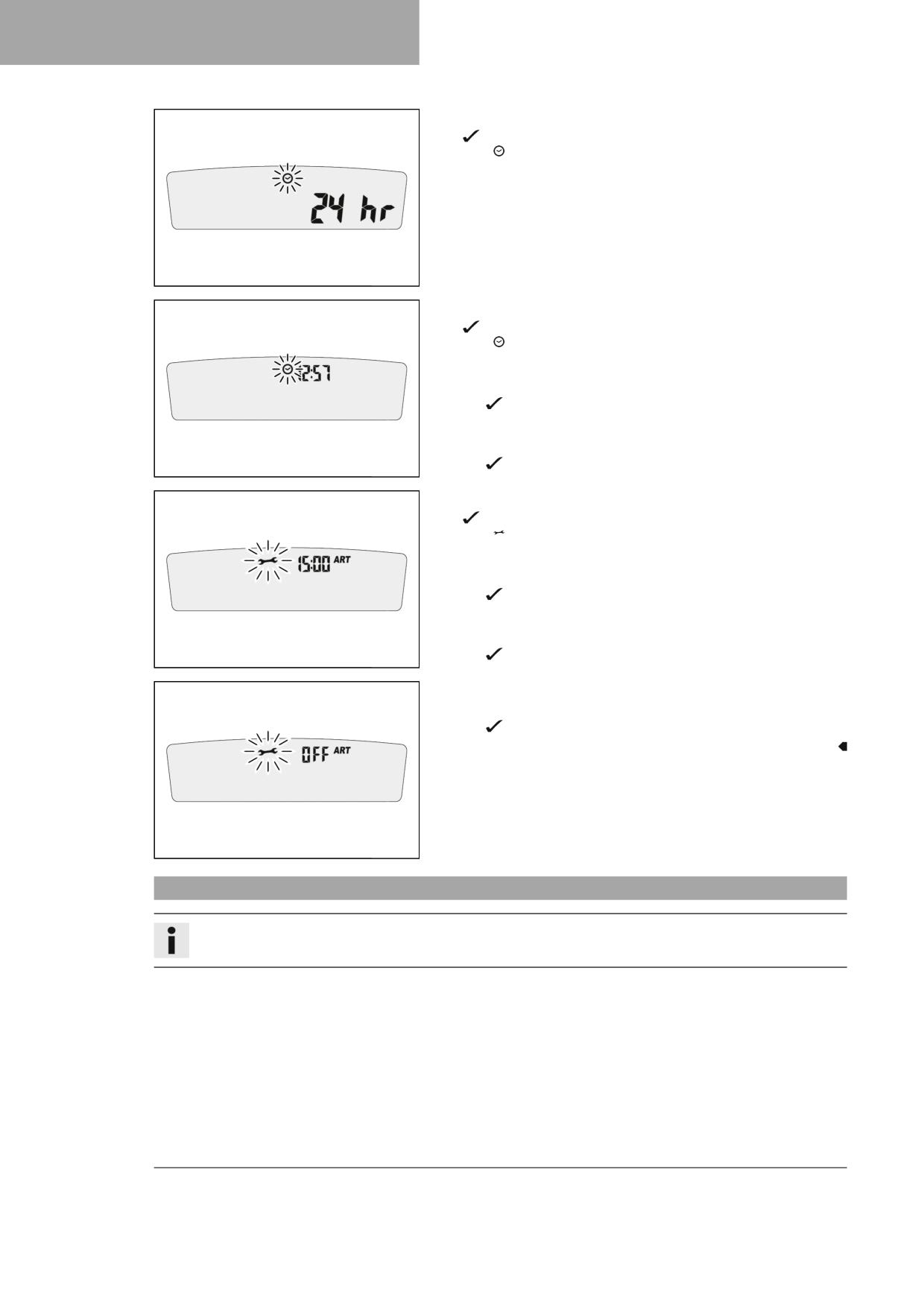
- Wait for 5 seconds.
Combination instrument changes to the next menu item. The
symbol flashes.
- Press one of the buttons to select the 24 h display or 12 h display for
the clock.
401911-01
- Wait for 5 seconds.
Combination instrument changes to the next menu item. The
symbol flashes.
Resetting the time
- Press the left button.
The value decreases.
Advancing the time
- Press the right button.
The value increases.
401912-01
- Wait for 5 seconds.
Combination instrument changes to the next menu item. The
symbol flashes.
Shortening the service interval
- Press the left button.
The value decreases.
Extending the service interval
- Press the right button.
The value increases.
401913-01
Switching off the service interval display
- Press and hold the left button.
off appears in the display.
401914-01
7.5
Setting kilometers or miles
Info
If the unit is changed, the value ODO is retained and converted accordingly.
Condition
The motorcycle is stationary.
24
COMBINATION INSTRUMENT
7
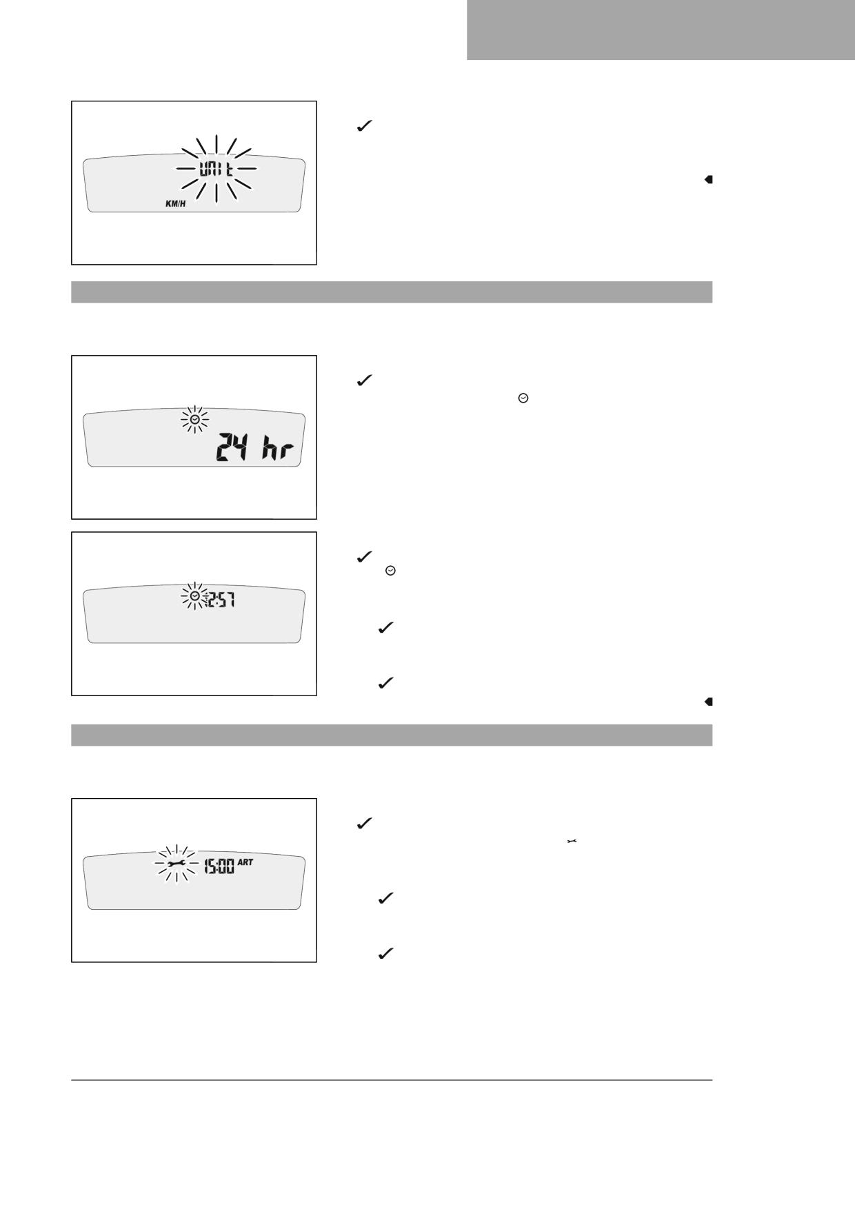
– Press and hold both buttons for 3 - 5 seconds.
The Setup menu is displayed. The UNIT display flashes.
- Press one of the buttons to select UNIT for the speed in kilometers
KM/H or miles M/H.
401909-01
7.6
Setting the clock
Condition
The motorcycle is stationary.
- Press and hold both buttons for 3 - 5 seconds.
The Setup menu is displayed. The UNIT display flashes.
- Wait for the menu of the clock to flash.
- Press one of the buttons to select the 24 h display or 12 h display for
the clock.
401911-01
- Wait for 5 seconds.
Combination instrument changes to the next menu item. The
symbol flashes.
Resetting the time
- Press the left button.
The value decreases.
Advancing the time
- Press the right button.
The value increases.
401912-01
7.7
Setting the service display
Condition
The motorcycle is stationary.
- Press and hold both buttons for 3 - 5 seconds.
The Setup menu is displayed. The UNIT display flashes.
- Wait for the menu of the service display to flash.
Shortening the service interval
- Press the left button.
The value decreases.
Extending the service interval
- Press the right button.
401913-01
The value increases.
25
7
COMBINATION INSTRUMENT
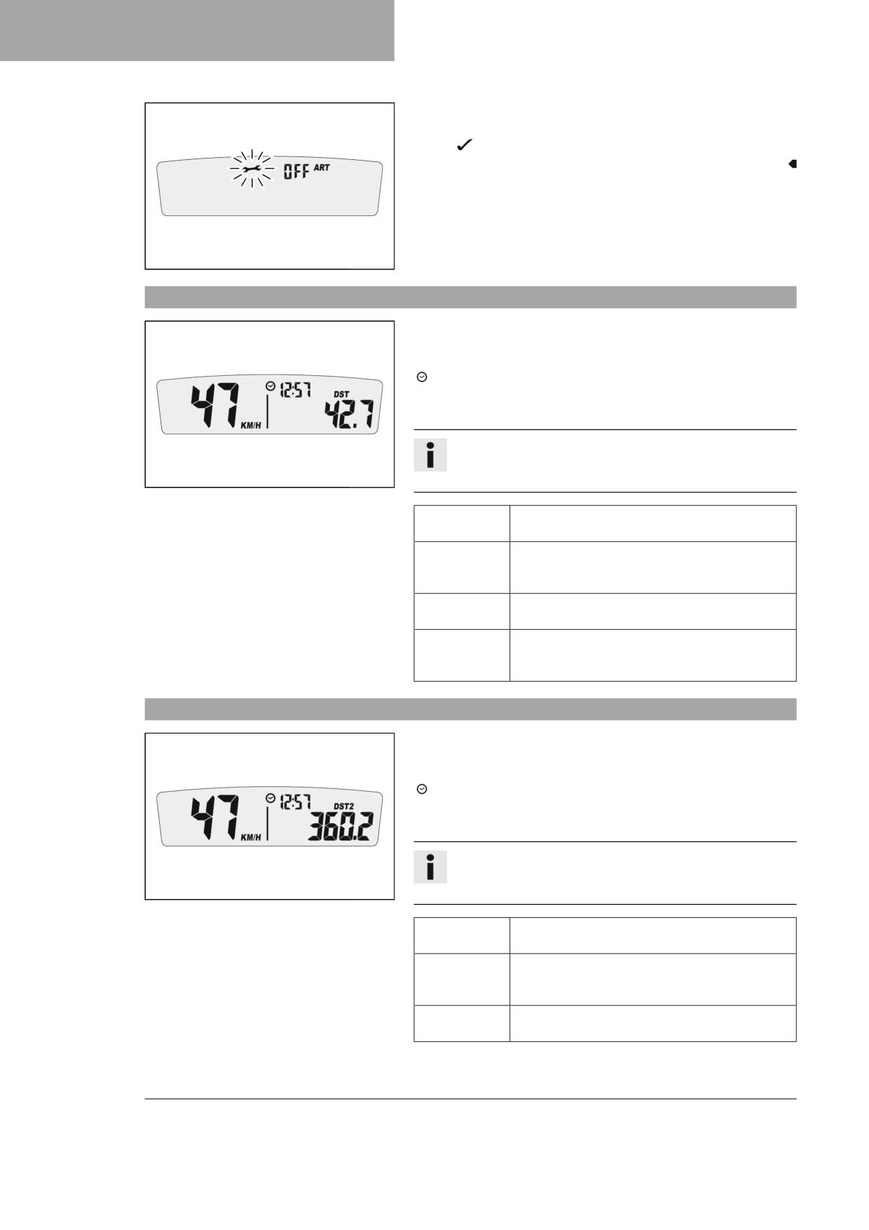
Switching off the service interval display
- Press and hold the left button.
off appears in the display.
401914-01
7.8
Speed, time, and DST distance 1
- Press one of the buttons until DST appears on the combination
instrument.
KM/H or M/H shows the speed.
shows the time.
DST shows the distance since the last reset, such as between two refuel-
ing stops.
Info
If the value of 39999.9 is exceeded, DST is automatically reset to
401901-01
0.0.
Press the left
Next display mode
button briefly.
Press the left
DST can be preset to a value between 0.0 and
button for 3 - 5
39999.9 by pressing the buttons.
seconds.
Press the right
Next display mode
button briefly.
Press the right
DST is reset to 0.0.
button for 3 - 5
seconds.
7.9
Speed, time, and DST2 distance 2
- Press one of the buttons until DST2 appears on the combination
instrument.
KM/H or M/H shows the speed.
shows the time.
DST2 shows the distance 2 since the last reset, such as between two
refueling stops.
Info
If the value of 39999.9 is exceeded, DST2 is automatically reset
401902-01
to 0.0.
Press the left
Next display mode
button briefly.
Press the left
DST2 can be preset to a value between 0.0 and
button for 3 - 5
39999.9 by pressing the buttons.
seconds.
Press the right
Next display mode
button briefly.
26

COMBINATION INSTRUMENT
7
Press the right
DST2 is reset to 0.0.
button for 3 - 5
seconds.
7.10
AVG average speed, ART operating hours, and ODO total distance covered
- Press one of the buttons until AVG, ART and ODO appear on the
combination instrument.
AVG shows the average speed since the last reset.
ART shows the operating hours.
ODO shows the total distance covered.
Press the left
Next display mode
button briefly.
Press the left
The OPEN END WRENCH SYMBOL shows the
button for 3 - 5
remaining operating hours until the next service is
401903-01
seconds.
due.
Press the right
Next display mode
button briefly.
Press the right
AVG is reset to 0.0.
button for 3 - 5
seconds.
27

8
PREPARING FOR USE
8.1
Advice on preparing for first use
Danger
Danger of accidents A rider who is not fit to ride poses a danger to him or herself and others.
- Do not operate the vehicle if you are not fit to ride due to alcohol, drugs or medication.
- Do not operate the vehicle if you are physically or mentally impaired.
Warning
Risk of injury Missing or poor protective clothing presents an increased safety risk.
- Wear appropriate protective clothing such as helmet, boots, gloves as well as trousers and a jacket with pro-
tectors on all rides.
- Always wear protective clothing that is in good condition and meets the legal regulations.
Warning
Danger of crashing Different tire tread patterns on the front and rear wheel impair the handling characteristic.
Different tire tread patterns can make the vehicle significantly more difficult to control.
- Make sure that only tires with a similar tire tread pattern are fitted to the front and rear wheel.
Warning
Danger of accidents An unadapted riding style impairs the handling characteristic.
- Adapt your riding speed to the road conditions and your riding ability.
Warning
Danger of accidents The vehicle is not designed to carry passengers.
- Do not ride with a passenger.
Warning
Danger of accidents The brake system fails in the event of overheating.
If the foot brake lever is not released, the brake linings drag continuously.
- Take your foot off the foot brake lever if you do not want to brake.
Warning
Danger of accidents Total weight and axle loads influence the handling characteristic.
- Do not exceed the maximum permissible overall weight or the axle loads.
Warning
Risk of injury People who act without authorization may not be familiar with the vehicle.
- Do not leave the vehicle unattended if the engine is running.
- Protect the vehicle against access by unauthorized persons.
Info
When using your motorcycle, remember that others may feel disturbed by excessive noise.
-
Make sure that the pre-sales inspection work has been carried out by an authorized GASGAS Motorcycles workshop.
You will receive a delivery certificate when the vehicle is handed over.
-
Before riding for the first time, read the entire Owner's Manual carefully.
–
Get to know the controls.
–
Adjust basic position of the clutch lever. ( p. 80)
–
Adjust basic position of the hand brake lever. ( p. 84)
–
Adjust the basic position of the foot brake lever.
(
p. 89)
–
Adjust the basic position of the shift lever.
(
p. 120)
28

PREPARING FOR USE
8
– Get used to the handling characteristics of the motorcycle on a suitable surface before undertaking more challenging
trips.
Info
When offroad, it is recommended that you are accompanied by another person on another vehicle so that you
can help each other.
- Try also to ride as slowly as possible and in a standing position to get a better feel for the motorcycle.
- Do not make any off-road trips that exceed your ability and experience.
- Hold the handlebar firmly with both hands and keep your feet on the footrests when riding.
- If you carry any luggage, make sure you fix it firmly as close as possible to the center of the vehicle and ensure even
weight distribution between the front and rear wheels.
Info
Motorcycles react sensitively to any changes of weight distribution.
- Do not exceed the maximum permissible weight and maximum permissible axle loads.
Guideline
Maximum permissible overall weight
335 kg (739 lb.)
Maximum permissible front axle load
145 kg (320 lb.)
Maximum permissible rear axle load
190 kg (419 lb.)
– Check the spoke tension. ( p. 100)
Info
The spoke tension must be checked after half an hour of operation.
- Run the engine in. ( p. 29)
8.2
Running in the engine
– Do not exceed the specified engine speed and load during the running-in time.
Guideline
Maximum engine speed
During the first operating hour
7,000 rpm
Maximum engine performance
During the first 3 operating hours
≤ 75 %
– Avoid fully opening the throttle.
8.3
Starting power of lithium-ion batteries at low temperatures
Lithium-ion batteries are far lighter than lead batteries, have a low self-
discharge rate, and have more starting power at temperatures over 6 °C
(43 °F).
Several attempts to start may be required. Press the start button for
5 seconds, and wait 15 seconds between attempts. At low tempera-
tures, wait for 30 seconds. The pauses are necessary so that the heat
created can distribute through the lithium-ion battery and the lithium-
ion battery is not damaged.
The starting power increases as the battery warms up.
Always make sure the lithium-ion battery is charged to that there is
402555-01
enough power to spare for starting at low temperatures.
After 6 unsuccessful starting attempts, do not try again, and check the
vehicle for other errors instead.
29
8
PREPARING FOR USE
8.4
Preparing the vehicle for difficult operating conditions
Info
Use of the vehicle under difficult conditions, such as on sand or on wet and muddy surfaces, can result in signifi-
cantly increased wear of components, such as the drive train, brake system, or suspension components. For this
reason, it may be necessary to inspect or replace parts before the next scheduled service.
- Clean the air filter and air filter box.
(
p. 65)
Info
Check the air filter approx. every 30 minutes.
- Check the connector for humidity and corrosion and to ensure it is firmly seated.
» If humidity, corrosion, or damage is found:
- Clean and dry the connector, or change it if necessary.
Difficult operating conditions are:
- Rides on dry sand. ( p. 30)
- Rides on wet sand. ( p. 31)
- Rides on wet and muddy circuits. ( p. 31)
- Rides at high temperatures or slow riding. ( p. 32)
- Riding at low temperatures and in snow. ( p. 32)
8.5
Preparing the vehicle for rides on dry sand
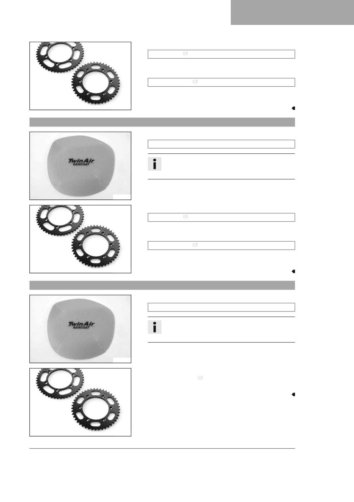
- Mount the air filter dust cover.
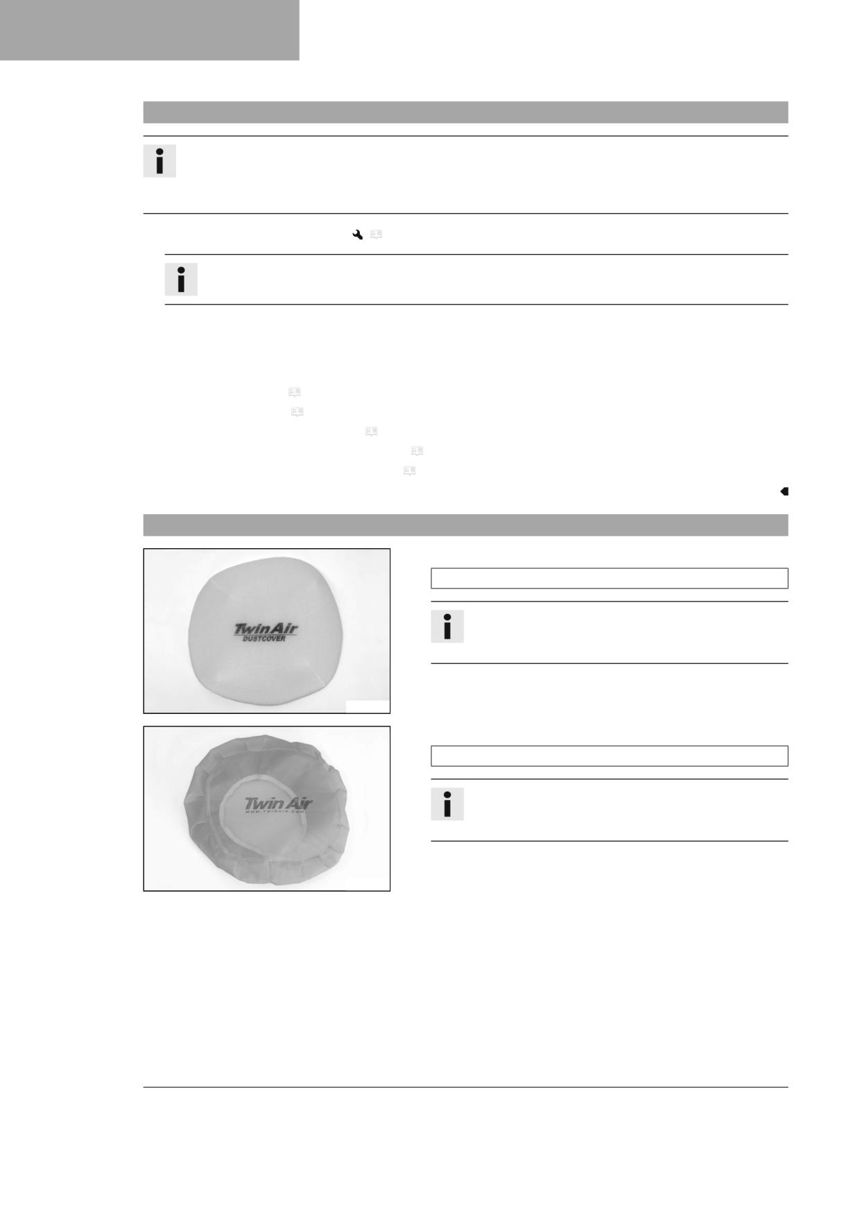
Air filter dust cover (79006920000)
Info
Observe the fitting instructions for GASGAS Techni-
cal Accessories.
102136-01
- Mount the air filter sand cover.
Air filter sand cover (79006922000)
Info
Observe the fitting instructions for GASGAS Techni-
cal Accessories.
102138-01
30
PREPARING FOR USE
8
– Clean the chain.
Chain cleaner ( p. 144)
- Mount the steel sprocket.
- Grease the chain.
Universal oil spray ( p. 145)
- Clean the radiator fins.
- Straighten the bent radiator fins carefully.
600868-01
8.6
Preparing the vehicle for rides on wet sand
- Mount the air filter rain cover.
Air filter rain cover (79006921000)
Info
Observe the fitting instructions for GASGAS Techni-
cal Accessories.
102137-01
- Clean the chain.
Chain cleaner ( p. 144)
- Mount the steel sprocket.
- Grease the chain.
Universal oil spray ( p. 145)
- Clean the radiator fins.
- Straighten the bent radiator fins carefully.
600868-01
8.7
Preparing the vehicle for rides on wet and muddy circuits
- Mount the air filter rain cover.
Air filter rain cover (79006921000)
Info
Observe the fitting instructions for GASGAS Techni-
cal Accessories.
102137-01
- Mount the steel sprocket.
- Clean the motorcycle. ( p. 126)
- Straighten the bent radiator fins carefully.
600868-01
31

8
PREPARING FOR USE
8.8
Preparing vehicle for high temperatures or slow riding
- Adjust the secondary drive to the road conditions.
Info
The engine oil heats up quickly when the clutch is operated
frequently due to an excessively high secondary ratio.
- Clean the chain.
Chain cleaner ( p. 144)
- Clean the radiator fins.
600868-01
- Straighten the bent radiator fins carefully.
- Check the coolant level. ( p. 112)
8.9
Preparing the vehicle for low temperatures or snow
- Mount the air filter rain cover.
Air filter rain cover (79006921000)
Info
Observe the fitting instructions for GASGAS Techni-
cal Accessories.
102137-01
32

RIDING INSTRUCTIONS
9
9.1
Checks and maintenance measures when preparing for use
Info
Before every trip, check the condition of the vehicle and ensure that it is safe to operate.
The vehicle must be in perfect technical condition when it is being operated.
-
Check the engine oil level. ( p. 122)
–
Check the electrical system.
–
Check the front brake fluid level. ( p. 84)
–
Check the rear brake fluid level. ( p. 90)
–
Check that the brake linings of the front brake are secured.
(
p. 86)
–
Check that the brake linings of the rear brake are secured. ( p. 92)
–
Check that the brake system is functioning properly.
H02217-01
-
Check the coolant level. ( p. 112)
–
Check for chain dirt accumulation. ( p. 73)
–
Check the chain, rear sprocket, engine sprocket, and chain guide.
(
p. 75)
–
Check the chain tension. ( p. 74)
–
Check the tire condition. ( p. 99)
–
Check the tire pressure. ( p. 99)
–
Check the spoke tension. ( p. 100)
Info
The spoke tension must be checked regularly as incorrect
spoke tension will strongly impair riding safety.
-
Clean the dust boots of the fork legs. ( p. 51)
–
Bleed the fork legs. ( p. 50)
–
Check the air filter.
–
Check the settings of all controls and ensure that they can be oper-
ated smoothly.
-
Check all screws, nuts, and hose clips regularly for tightness.
–
Check the fuel level.
9.2
Starting the vehicle
Danger
Danger of poisoning Exhaust gases are toxic and inhaling them may result in unconsciousness and death.
- Always make sure there is sufficient ventilation when running the engine.
- Use effective exhaust extraction when starting or running the engine in an enclosed space.
Note
Engine damage High revving speed with a cold engine negatively impacts the lifespan of the engine.
- Always run the engine warm at a low speed.
33
9
RIDING INSTRUCTIONS
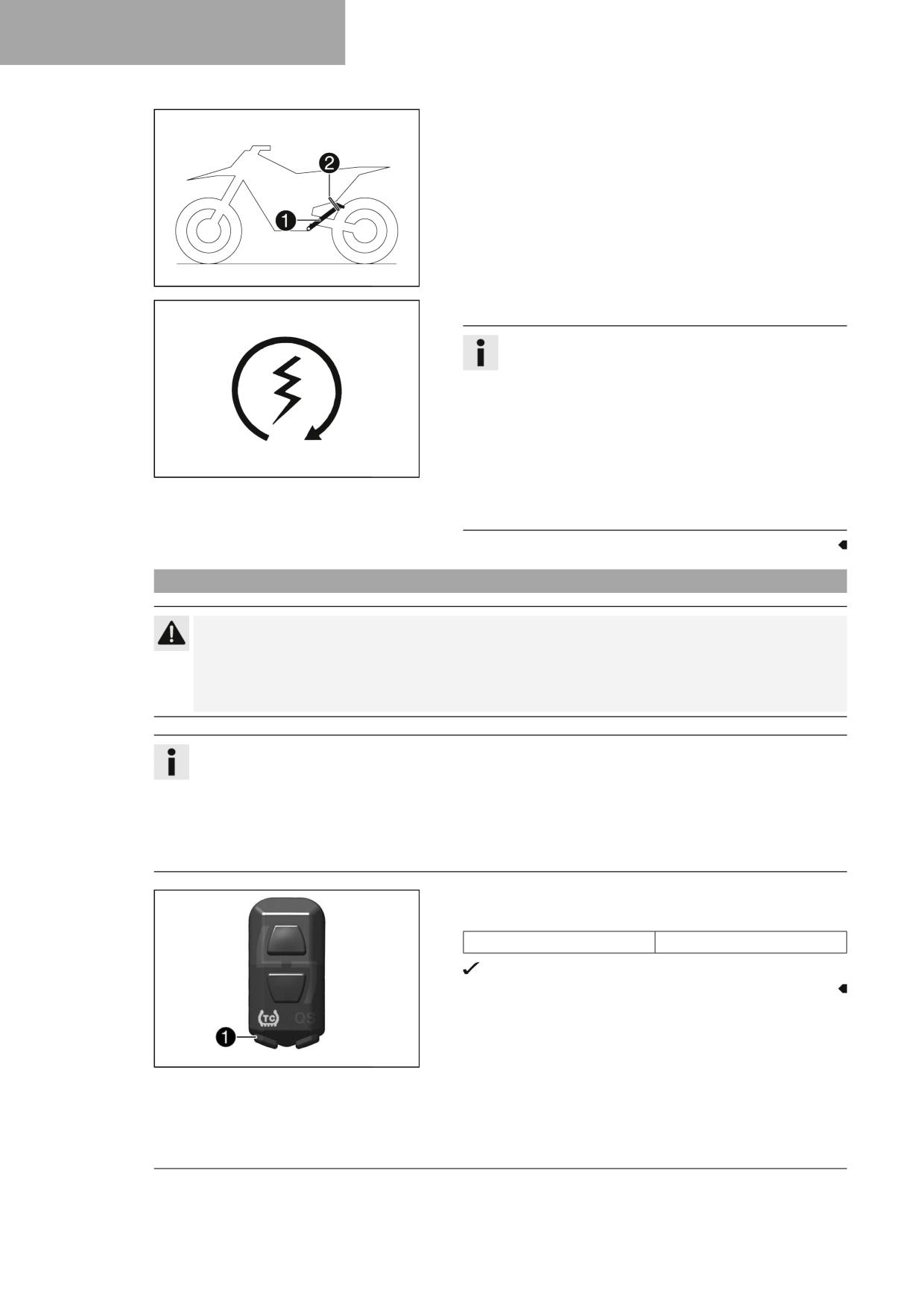
- Take the motorcycle off side stand 1 and secure the side stand
with rubber strap 2.
- Shift the transmission into neutral.
Condition
Ambient temperature: < 20 °C (< 68 °F)
- Push the cold start button in all the way.
401944-10
- Press the start button.
Info
Press the start button for a maximum of 5 seconds. Wait for
15 seconds before a further attempt at starting.
At low temperatures, wait for 30 seconds.
At temperatures below 6 °C (43 °F), several attempts at
starting may be necessary to warm-up the lithium-ion bat-
tery and thereby increase the starting power.
After 6 unsuccessful starting attempts, do not try again, and
400733-01
check the vehicle for other errors instead.
During the starting process, the malfunction indicator lamp
lights up.
9.3
Activating traction control (optional)
Caution
Voiding of the government approval for road use and the insurance coverage If the combination switch is
mounted, the vehicle’s road permit, if any, expires.
- Only operate the vehicle in closed-off areas remote from public road traffic if the combination switch is
installed.
Info
The traction control reduces excessive slip on the rear wheel in favor of more control and propulsion, particularly in
wet conditions.
When traction control is switched off, the rear wheel may spin more during high acceleration and on surfaces with
low grip.
Traction control can be switched on or off during the ride.
The setting most recently selected is activated again when restarting.
- Press the TC button 1 to switch traction control on or off.
Guideline
Engine speed
≤ 4,000 rpm
The TC LED lights up when the traction control is activated.
F03760-11
34
RIDING INSTRUCTIONS
9
9.4
Starting off
Info
When you are riding, the side stand must be folded up and secured with the rubber strap.
- Pull the clutch lever, shift into first gear, release the clutch lever slowly and at the same time open the throttle carefully.
9.5
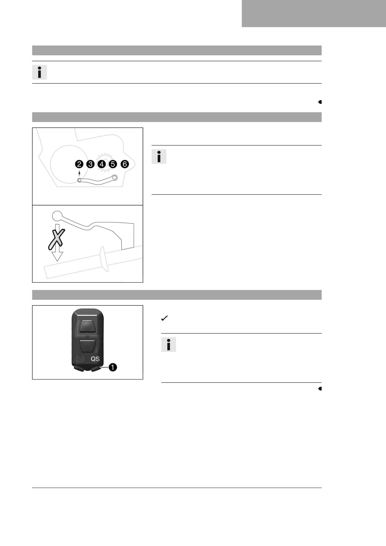
Quickshifter (optional)
When the quickshifter is activated, you can shift up without actuating
the clutch.
Info
The quickshifter is not activated when shifting up from first to
second gear, and the clutch lever must be used when shifting up
instead.
Even if the quickshifter is activated, you need to use the clutch
lever to shift down.
Because there is no need to close the throttle grip, uninterrupted gear
shifts are possible.
The quickshifter uses the shifter shaft position to check whether or not a
shift should be initiated, and sends a corresponding signal to the engine
control.
If the quickshifter is deactivated, the clutch needs to be actuated in the
normal way for each shift.
S05784-10
9.6
Activating the quickshifter (optional)
- Press the QS button 1 to switch the quickshifter on or off.
The QS indicator lamp lights up when the quickshifter is acti-
vated.
Info
The quickshifter is not activated when shifting up from first
to second gear, and the clutch lever must be used when
shifting up instead.
Even if the quickshifter is activated, you need to use the
F03760-12
clutch lever to shift down.
35

9
RIDING INSTRUCTIONS
9.7
Shifting, riding
Warning
Danger of accidents If you change down at high engine speed, the rear wheel blocks and the engine races.
- Do not change into a low gear at high engine speed.
Info
If you hear unusual noises while riding, stop immediately, switch off the engine, and contact an authorized GAS-
GAS Motorcycles workshop.
First-gear is used for starting off and for steep inclines.
- Shift into a higher gear when conditions allow (incline, road situation, etc.). To do so, release the throttle while simulta-
neously pulling the clutch lever, shift into the next gear, release the clutch lever and open the throttle.
- After reaching maximum speed by fully opening the throttle grip, turn the throttle back so it is ¾ open. This will barely
reduce the speed, but fuel consumption will be considerably lower.
- Always open the throttle only as much as the engine can handle - abrupt throttle opening increases fuel consumption.
- To shift down, apply the brakes and close the throttle at the same time.
- Pull the clutch lever and shift into a lower gear, release the clutch lever slowly, and either open the throttle or shift
again.
- Switch off the engine if running at idle speed or stationary for a long time.
Guideline
≥ 2 min
- Avoid frequent and lengthy slipping of the clutch. This causes the engine oil, engine and cooling system to heat up.
- Ride at a low engine speed instead of at a high engine speed with a slipping clutch.
9.8
Braking
Warning
Danger of accidents Excessively forceful application of the brakes blocks the wheels.
- Adjust application of the brakes to the respective riding situation and riding surface conditions.
Warning
Danger of accidents A spongy pressure point on the front or rear brake reduces braking efficiency.
- Check the brake system and do not continue riding until the problem is eliminated. (Your authorized GAS-
GAS Motorcycles workshop will be glad to help.)
Warning
Danger of accidents Moisture and dirt impair the brake system.
- Brake carefully several times to dry out and remove dirt from the brake linings and the brake discs.
- On sandy, wet, or slippery surfaces, use the rear brake.
- Always finish braking before you go into a bend. Change down to a lower gear appropriate to your road speed.
- Use the braking effect of the engine on long downhill stretches. Change down one or two gears, but do not over-rev the
engine. You will have to apply the brakes far less frequently as a result and the brake system will not overheat.
36

RIDING INSTRUCTIONS
9
9.9
Stopping, parking
Warning
Risk of injury People who act without authorization may not be familiar with the vehicle.
- Do not leave the vehicle unattended if the engine is running.
- Protect the vehicle against access by unauthorized persons.
Warning
Danger of burns Some vehicle components become hot when the vehicle is operated.
- Do not touch any parts such as the exhaust system, radiator, engine, damper, or brake system before the vehi-
cle parts have cooled down.
- Let the vehicle parts cool down before you perform any work on the vehicle.
Note
Fire hazard Hot vehicle components pose a fire hazard and explosion risk.
- Do not park the vehicle near to materials which are highly flammable or explosive.
- Allow the vehicle to cool down before covering it.
Note
Material damage The vehicle may be damaged by incorrect procedure when parking.
Significant damage may be caused if the vehicle rolls away or falls over.
The components for parking the vehicle are designed only for the weight of the vehicle.
- Park the vehicle on a firm and level surface.
- Ensure that nobody sits on the vehicle when the vehicle is parked on a stand.
- Apply the brakes on the motorcycle.
- Shift the transmission into neutral.
- Press and hold the stop button while the engine is idling until the engine stops.
- Park the motorcycle on firm ground.
9.10
Transporting
Note
Material damage The vehicle may be damaged by incorrect procedure when parking.
Significant damage may be caused if the vehicle rolls away or falls over.
The components for parking the vehicle are designed only for the weight of the vehicle.
- Park the vehicle on a firm and level surface.
- Ensure that nobody sits on the vehicle when the vehicle is parked on a stand.
Note
Fire hazard Hot vehicle components pose a fire hazard and explosion risk.
- Do not park the vehicle near to materials which are highly flammable or explosive.
- Allow the vehicle to cool down before covering it.
37

9
RIDING INSTRUCTIONS
- Switch off the engine.
- Use tension belts or other suitable devices to secure the motorcycle
against falling over or rolling away.
401475-01
9.11
Refueling
Danger
Fire hazard Fuel is highly flammable.
The fuel in the fuel tank expands when warm and can escape if overfilled.
- Do not fuel the vehicle in the vicinity of open flames or lit cigarettes.
- Switch off the engine for refueling.
- Make sure that no fuel is spilled; particularly not on hot parts of the vehicle.
- If any fuel is spilled, wipe it off immediately.
- Observe the specifications for refueling.
Warning
Danger of poisoning Fuel is harmful to health.
- Avoid skin, eye and clothing contact with fuel.
- Immediately consult a doctor if you swallow fuel.
- Do not inhale fuel vapors.
- Rinse the affected area immediately with plenty of water in the event of contact with the skin.
- Rinse the eyes thoroughly with water, and consult a doctor in case of fuel contact with the eyes.
- Change your clothing if fuel spills on them.
Note
Material damage Inadequate fuel quality causes the fuel filter to quickly become clogged.
In some countries and regions, the available fuel quality and cleanliness may not be sufficient. This will result in problems
with the fuel system.
- Refuel only with clean fuel that meets the specified standards. (Your authorized GASGAS Motorcycles workshop will be
glad to help.)
Note
Environmental hazard Improper handling of fuel is a danger to the environment.
- Do not allow fuel to enter the groundwater, the soil, or the sewage system.
- Switch off the engine.
- Open fuel tank filler cap. ( p. 18)
38

RIDING INSTRUCTIONS
9
– Fill the fuel tank with fuel up to level A.
Guideline
35 mm (1.38 in)
Level A
Total fuel tank capac-
8.5 l
Super unleaded (ROZ
ity, approx.
(2.25 US gal)
95) ( p. 143)
– Close the fuel tank filler cap. ( p. 19)
F03269-10
39
10
SERVICE SCHEDULE
10.1
Additional information
Any further work that results from the service work must be ordered separately and invoiced separately.
Different service intervals may apply in your country, depending on the local operating conditions.
Individual service intervals and scopes may change in the course of technical developments. The most up-to-date service
schedule can always be found on GASGAS Motorcycles Dealer.net. Your authorized GASGAS Motorcycles dealer will be glad
to advise you.
10.2
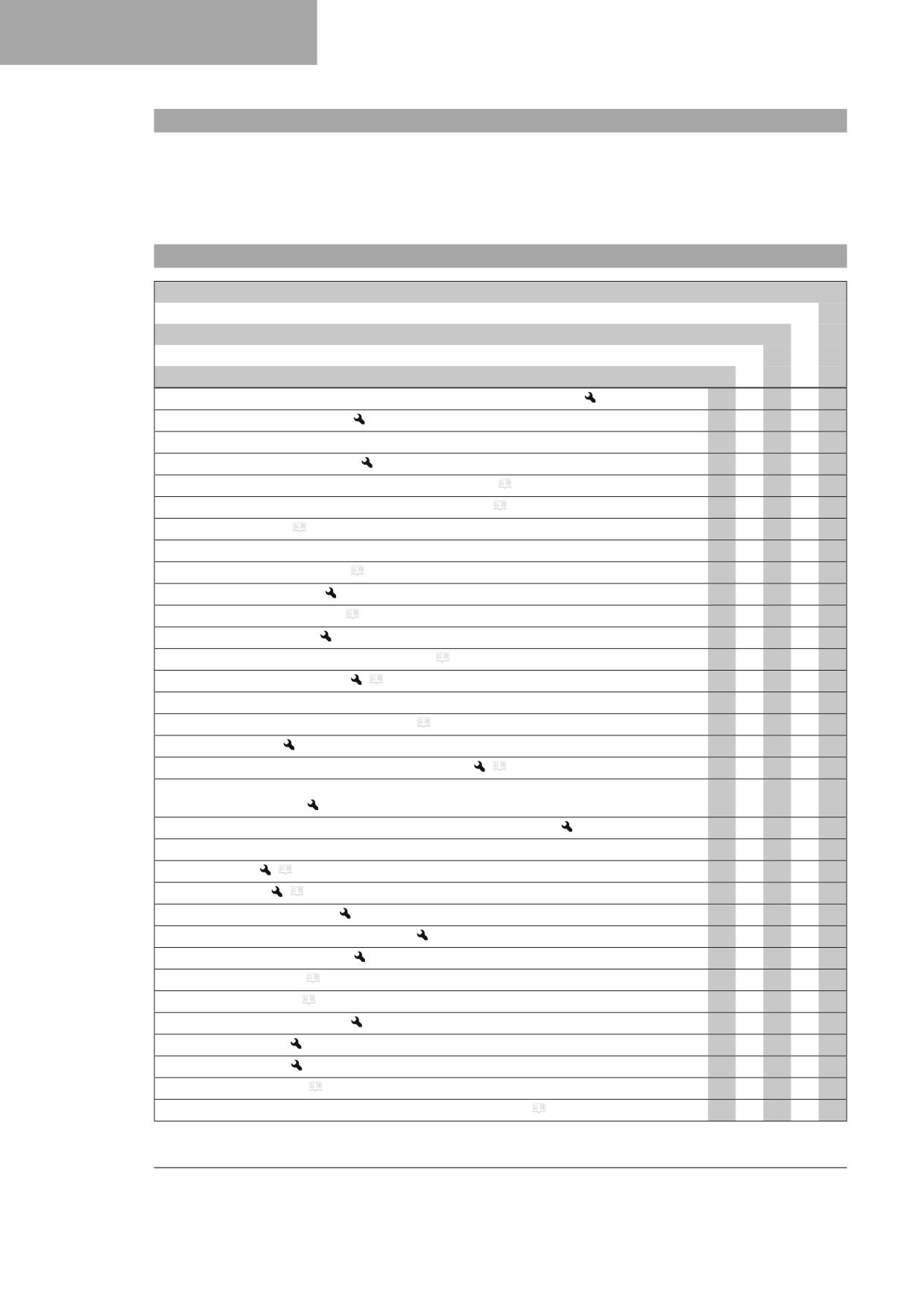
Service schedule
every 24 months
Every 90 operating hours
Every 45 operating hours
Every 15 operating hours
After 1 operating hour
Read out the fault memory using the GASGAS Motorcycles diagnostics tool.
○
●
●
●
●
Program the gear position sensor.
●
●
●
Check that the electrical system is functioning properly.
○
●
●
●
Check and charge the 12-V battery.
●
●
●
●
Check that the brake linings of the front brake are secured. ( p. 86)
●
●
●
●
Check that the brake linings of the rear brake are secured. ( p. 92)
●
●
●
●
Check the brake discs. ( p. 84)
●
●
●
●
Check the brake lines for damage and tightness.
●
●
●
●
Check the front brake fluid level. ( p. 84)
●
●
Change the front brake fluid.
●
●
Check the rear brake fluid level. ( p. 90)
●
●
Change the rear brake fluid.
●
●
Check/correct the fluid level of hydraulic clutch. ( p. 81)
●
Change the hydraulic clutch fluid.
(
p. 82)
●
●
Check the free travel of the hand brake lever.
○
●
●
●
●
Check the free travel of the foot brake lever. ( p. 89)
●
●
●
●
Check the idle speed.
○
●
●
●
●
Change the engine oil and oil filter, clean the oil screen.
(
p. 122)
○
●
●
●
●
Check all hoses (e.g. fuel, cooling, bleeder, drainage hoses, etc.) and sleeves for cracking, tight-
○
●
●
●
●
ness, and correct routing.
Check the cables for damage and that there are no kinks in the routing.
●
●
●
●
Check that the throttle cables are undamaged, routed without kinks, and set correctly.
●
●
●
Check the frame.
(
p. 78)
●
●
●
Check the link fork.
(
p. 78)
●
●
●
Check the fork bearing for play.
●
●
Check the shock absorber heim joint for play.
●
●
Check the shock absorber linkage.
●
●
●
Check the tire condition. ( p. 99)
●
●
●
●
Check the tire pressure. ( p. 99)
●
●
●
●
Check the wheel bearing for play.
●
●
●
Check the wheel hubs.
●
●
●
Check the rim run-out.
○
●
●
●
Check the spoke tension. ( p. 100)
○
●
●
●
Check the chain, rear sprocket, engine sprocket, and chain guide. ( p. 75)
○
●
●
●
40
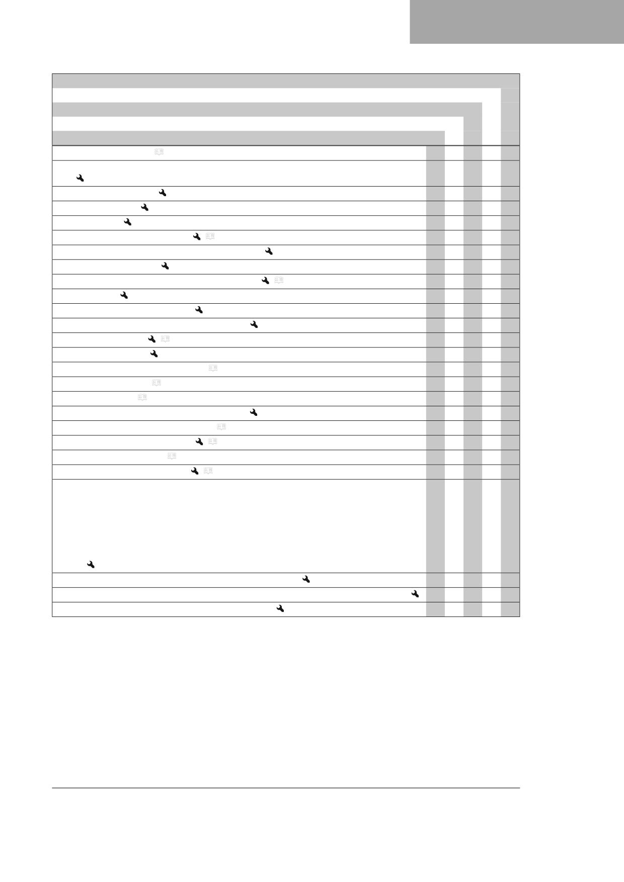
SERVICE SCHEDULE
10
every 24 months
Every 90 operating hours
Every 45 operating hours
Every 15 operating hours
After 1 operating hour
Check the chain tension. ( p. 74)
○
●
●
●
●
Grease all moving parts (e.g. side stand, hand lever, chain, etc.) and check for smooth opera-
○
●
●
●
●
tion.
Check the valve clearance.
○
●
●
Change the fuel filter.
●
●
Check the clutch.
●
●
Clean the air filter and air filter box.
(
p. 65)
●
●
●
●
Check the funnel in the inlet sleeve in the air filter box. (All EC models)
●
●
●
●
Check the inlet membrane. (EW 500F US)
●
●
Change the glass fiber yarn filling in the main silencer.
(
p. 69)
●
●
Service the fork.
●
●
Perform the shock absorber service.
●
●
Check all screws, nuts, and hose clips for a tight fit.
○
●
●
●
●
Change the fuel screen.
(
p. 121)
○
●
●
●
●
Check the fuel pressure.
○
●
●
●
Check the antifreeze and coolant level. ( p. 111)
●
●
Check the coolant level. ( p. 112)
○
●
Change the coolant. ( p. 114)
●
Check that the radiator fan is functioning properly.
○
●
●
●
Check the steering head bearing for play. ( p. 57)
○
●
Lubricate the steering head bearing.
(
p. 58)
●
●
●
Check the headlight setting. ( p. 107)
●
●
●
Clean spark arrestor. (EW 500F US)
(
p. 67)
●
●
Perform engine service including removing and installing the engine. (Change the spark plug
●
and spark plug connector. Change the piston. Check/measure the cylinder. Check the cylin-
der head. Change the valves, valve springs, valve spring retainers and valve spring seats. Check
the camshaft, rocker arm and rocker arm shafts. Change the connecting rod, conrod bearing
and crank pin. Check the transmission and the shift mechanism. Check the oil pressure control
valve. Change the suction pump. Check the force pump and lubrication system. Check the timing
assembly. Change the timing chain. Change all engine bearings and all gaskets. Change the free-
wheel.)
Final check: Check the vehicle is roadworthy and take a test ride.
○
●
●
●
●
Read out the fault memory after the test ride using the GASGAS Motorcycles diagnostics tool.
○
●
●
●
●
Make a service entry in GASGAS Motorcycles Dealer.net.
○
●
●
●
●
○ One-time interval
● Periodic interval
41
11
TUNING THE CHASSIS
11.1
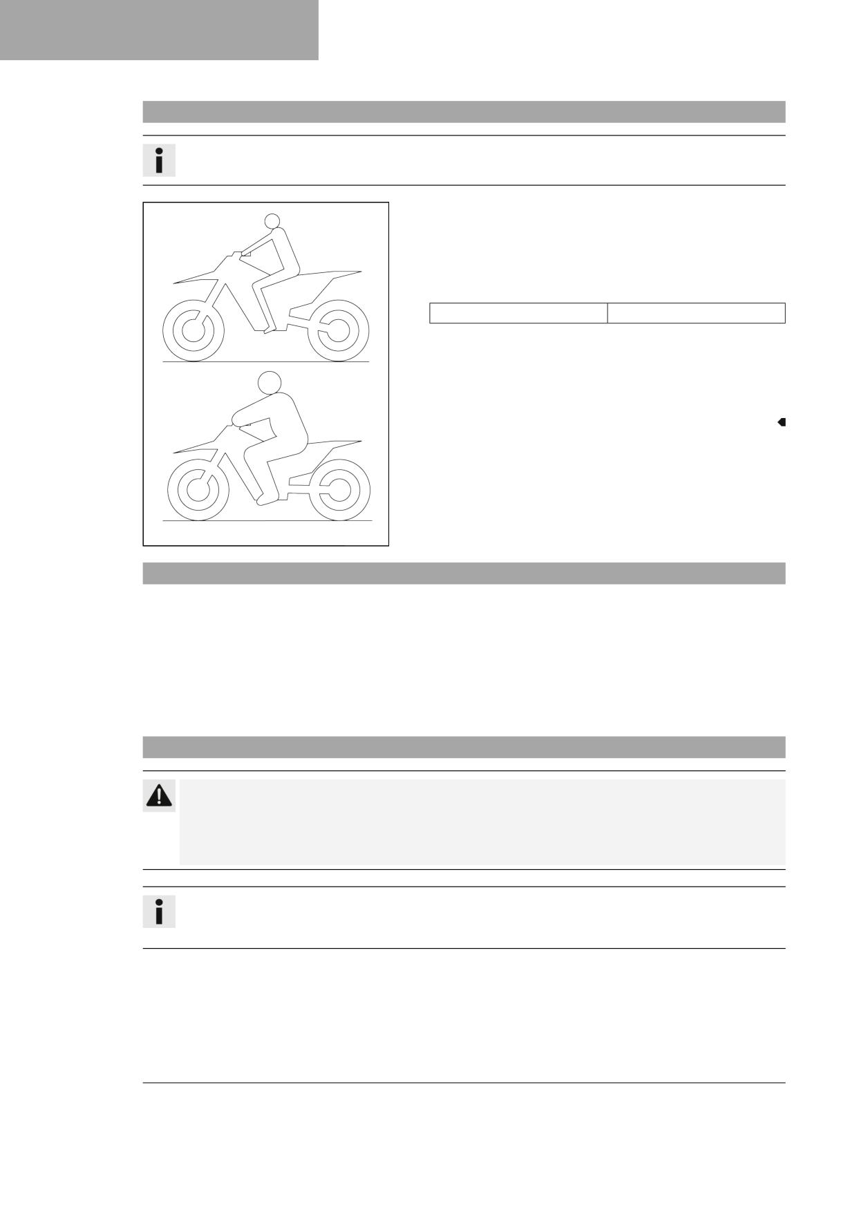
Checking the basic chassis setting with the rider's weight
Info
When adjusting the basic chassis setting, first adjust the shock absorber and then the fork.
- For optimal motorcycle riding characteristics and to avoid damage
to forks, shock absorbers, link fork and frame, the basic settings of
the suspension components must match the rider's weight.
- As delivered, GASGAS offroad motorcycles are adjusted for an aver-
age rider's weight (with full protective clothing).
Guideline
Standard rider weight
75 … 85 kg (165 … 187 lb.)
– If the rider's weight is above or below this range, the basic setting of
the suspension components must be adjusted accordingly.
- Small weight differences can be compensated by adjusting the
spring preload, but in the case of large weight differences, the
springs must be replaced.
401030-01
11.2
Compression damping of the shock absorber
The compression damping of the shock absorber is divided into two ranges: high-speed and low-speed.
High-speed and low-speed refer to the compression speed of the rear wheel suspension and not to the vehicle speed.
The high-speed compression adjuster has an effect, for example, when landing after a jump: the rear wheel suspension
compresses quickly.
The low-speed compression adjuster has an effect, for example, when riding over long ground swells: the rear wheel sus-
pension compresses slowly.
These two ranges can be adjusted separately, although the transition between high-speed and low-speed is gradual. Thus,
modifications in the high-speed range affect the compression damping in the low-speed range and vice versa.
11.3
Adjusting the low-speed compression damping of the shock absorber
Caution
Risk of injury Parts of the shock absorber will move around if the shock absorber is detached incorrectly.
The shock absorber is filled with highly compressed nitrogen.
- Please follow the description provided. (Your authorized GASGAS Motorcycles workshop will be glad to help.)
Info
The effect of the low-speed compression adjuster can be seen in slow to normal compression of the shock
absorber.
42
TUNING THE CHASSIS
11
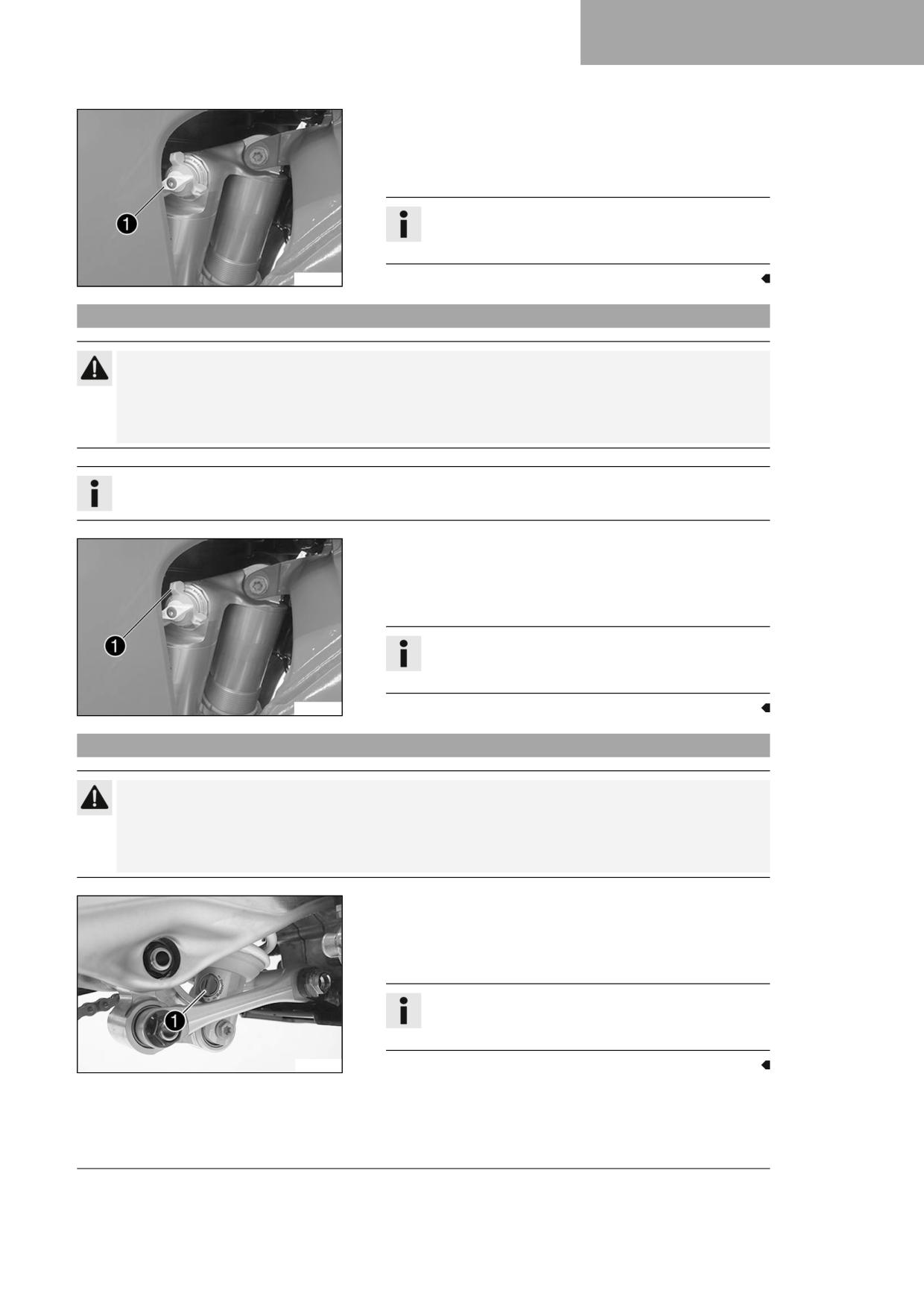
– Turn adjuster 1 clockwise up to the last perceptible click.
- Turn counterclockwise by the number of clicks corresponding to the
shock absorber type.
Guideline
Info
Turn clockwise to increase damping; turn counterclockwise
to reduce damping during compression.
A01323-10
11.4
Adjusting the high-speed compression damping of the shock absorber
Caution
Risk of injury Parts of the shock absorber will move around if the shock absorber is detached incorrectly.
The shock absorber is filled with highly compressed nitrogen.
- Please follow the description provided. (Your authorized GASGAS Motorcycles workshop will be glad to help.)
Info
The effect of the high speed compression adjuster can be seen in the fast compression of the shock absorber.
- Turn adjuster 1 clockwise up to the last perceptible click.
- Turn counterclockwise by the number of turns corresponding to the
shock absorber type.
Guideline
Info
Turn clockwise to increase damping; turn counterclockwise
to reduce damping during compression.
A01324-10
11.5
Adjusting the rebound damping of the shock absorber
Caution
Risk of injury Parts of the shock absorber will move around if the shock absorber is detached incorrectly.
The shock absorber is filled with highly compressed nitrogen.
- Please follow the description provided. (Your authorized GASGAS Motorcycles workshop will be glad to help.)
- Turn adjusting screw 1 clockwise up to the last perceptible click.
- Turn counterclockwise by the number of clicks corresponding to the
shock absorber type.
Guideline
Info
Turn clockwise to increase the damping; turn counterclock-
wise to reduce damping when the shock absorber rebounds.
S05733-10
43
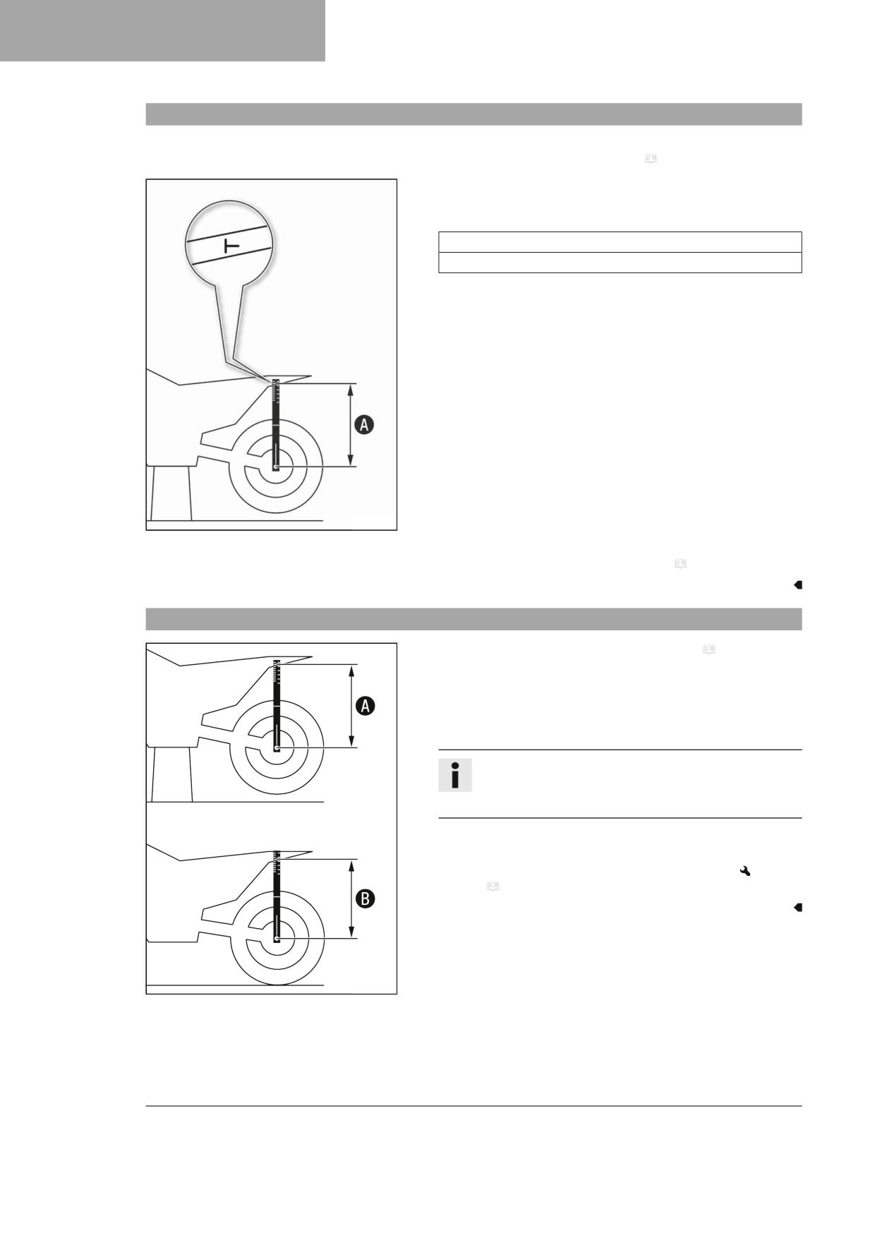
11
TUNING THE CHASSIS
11.6
Measuring the dimension of the rear wheel unloaded
Preparatory work
- Raise the motorcycle with a lift stand. ( p. 50)
Main work
- Position the sag gage in the rear axle and measure the distance to
the marking on the rear fender.
Sag gauge (00029090100)
Pin, sag scale (00029990010)
- Note the value as dimension A.
F03178-10
Finishing work
- Remove the motorcycle from the lift stand. ( p. 50)
11.7
Checking the static sag of the shock absorber
- Measure dimension A of rear wheel unloaded. ( p. 44)
- Hold the motorcycle upright with aid of an assistant.
- Remeasure the distance between the rear axle and the marking on
the rear fender using the sag gage.
- Note the value as dimension B.
Info
The static sag is the difference between measurements A
and B.
- Check the static sag.
» If the static sag is less or more than the specified value:
- Adjust the spring preload of the shock absorber.
(
p. 45)
402416-10
44
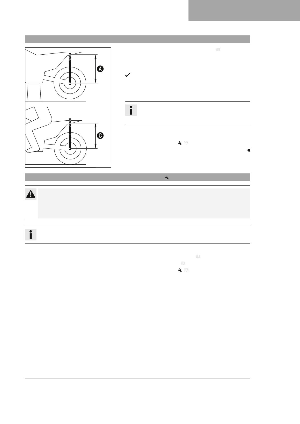
TUNING THE CHASSIS
11
11.8
Checking the rider sag of the shock absorber
- Measure dimension A of rear wheel unloaded. ( p. 44)
- With another person holding the motorcycle, the rider, wearing full
protective clothing, sits on the seat in a normal sitting position (feet
on footrests) and bounces up and down a few times.
The rear wheel suspension levels out.
- Another person now remeasures the distance between the rear axle
and the marking on the rear fender using the sag gage.
- Note the value as dimension C.
Info
The rider sag is the difference between measurements A
and C.
- Check the rider sag.
» If the rider sag differs from the specified measurement:
- Adjust the rider sag.
(
p. 46)
402417-10
11.9
Adjusting the spring preload of the shock absorber
Caution
Risk of injury Parts of the shock absorber will move around if the shock absorber is detached incorrectly.
The shock absorber is filled with highly compressed nitrogen.
- Please follow the description provided. (Your authorized GASGAS Motorcycles workshop will be glad to help.)
Info
Before changing the spring preload, make a note of the present setting, e.g., by measuring the spring length.
Preparatory work
- Raise the motorcycle with a lift stand. ( p. 50)
- Remove the frame protector. ( p. 53)
- Remove the shock absorber.
(
p. 59)
– After removing the shock absorber, clean it thoroughly.
45
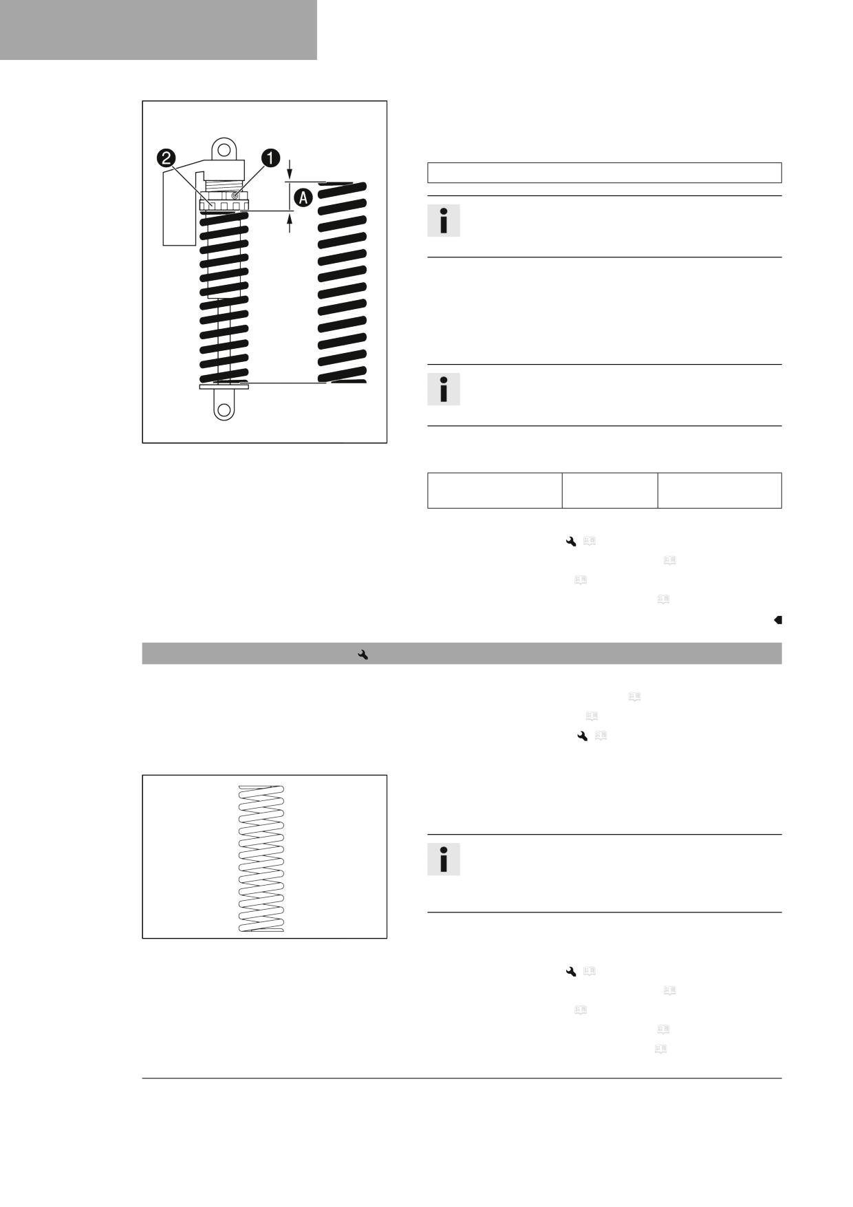
11
TUNING THE CHASSIS
Main work
- Loosen screw 1.
- Turn adjusting ring 2 until the spring is no longer under tension.
Hook wrench (90129051000)
Info
If the spring cannot be fully released, the spring must be
removed to accurately measure the spring length.
- Measure the total spring length while the spring is not under ten-
sion.
- Tension the spring by turning adjusting ring 2 to specified dimen-
sion A.
Guideline
Info
Depending on the static sag and/or the rider sag, it may be
necessary to increase or decrease the spring preload.
402659-10
- Tighten screw 1.
Guideline
Screw, shock absorber
M5
5 Nm (3.7 lbf ft)
adjusting ring
Finishing work
- Install the shock absorber.
(
p. 60)
– Check the free travel of the foot brake lever. ( p. 89)
- Install the frame protector. ( p. 54)
- Remove the motorcycle from the lift stand. ( p. 50)
11.10
Adjusting the rider sag
Preparatory work
- Raise the motorcycle with a lift stand. ( p. 50)
- Remove the frame protector. ( p. 53)
- Remove the shock absorber.
(
p. 59)
– After removing the shock absorber, clean it thoroughly.
Main work
- Select and mount a suitable spring.
Guideline
Info
The spring rate is shown on the outside of the spring.
Smaller weight differences can be compensated by changing
the spring preload.
B00292-10
Finishing work
- Install the shock absorber.
(
p. 60)
– Check the free travel of the foot brake lever. ( p. 89)
- Install the frame protector. ( p. 54)
- Remove the motorcycle from the lift stand. ( p. 50)
- Check the static sag of the shock absorber. ( p. 44)
46
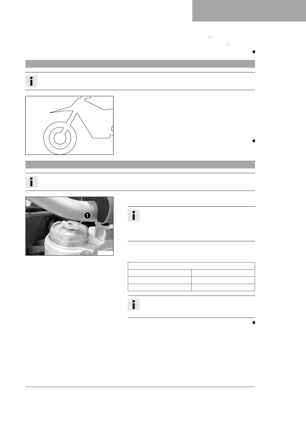
TUNING THE CHASSIS
11
– Check the rider sag of the shock absorber. ( p. 45)
- Adjust the rebound damping of the shock absorber. ( p. 43)
11.11
Checking the basic setting of the fork
Info
For various reasons, no exact rider sag can be determined for the fork.
- As with the shock absorber, smaller differences in the rider's weight
can be compensated by the spring preload.
- However, if the fork frequently bottoms out (hard end stop on com-
pression), harder springs must be fitted to avoid damage to the fork
and frame.
- If the fork feels unusually hard after extended periods of operation,
the fork legs need to be bled.
401000-01
11.12
Adjusting the compression damping of the fork
Info
The hydraulic compression damping determines the fork suspension behavior.
- Turn white adjuster 1 clockwise as far as it will go.
Info
Adjuster 1 is located at the upper end of the left fork leg.
The compression damping is located in left fork leg COMP
(white adjuster). The rebound damping is located in right
fork leg REB (red adjuster).
- Turn counterclockwise by the number of clicks corresponding to the
F03174-10
fork type.
Guideline
Compression damping
Comfort
18 clicks
Standard
15 clicks
Sport
12 clicks
Info
Turn clockwise to increase damping; turn counterclockwise
to reduce damping during compression.
47
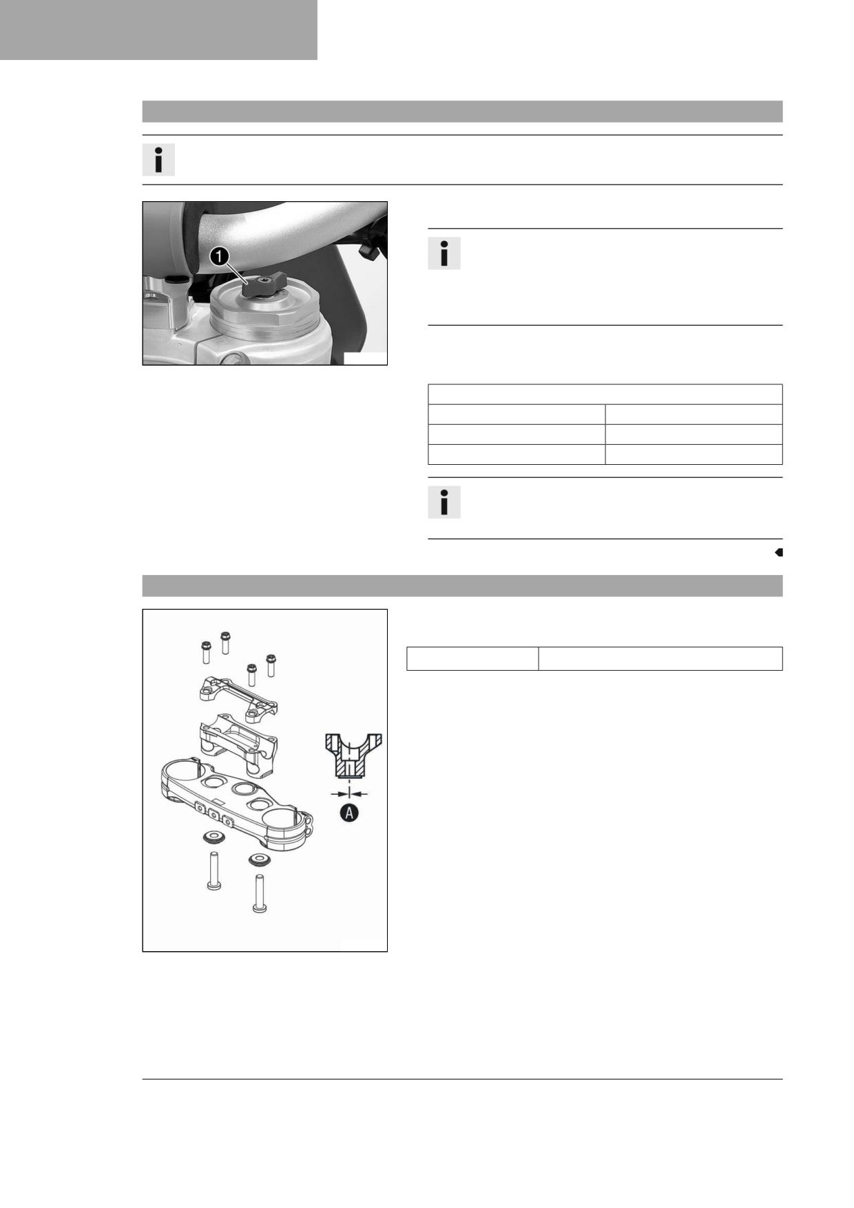
11
TUNING THE CHASSIS
11.13
Adjusting the rebound damping of the fork
Info
The hydraulic rebound damping determines the fork suspension behavior.
- Turn red adjuster 1 clockwise as far as it will go.
Info
Adjuster 1 is located at the upper end of the right fork leg.
The rebound damping is located in right fork leg REB (red
adjuster). The compression damping is located in left fork
leg COMP (white adjuster).
- Turn counterclockwise by the number of clicks corresponding to the
F03175-10
fork type.
Guideline
Rebound damping
Comfort
18 clicks
Standard
15 clicks
Sport
12 clicks
Info
Turn clockwise to increase the damping; turn counterclock-
wise to reduce damping when the shock absorber rebounds.
11.14
Handlebar position
The holes on the handlebar support are placed at a distance of A from
the center.
3.5 mm (0.138 in)
Hole distance A
The handlebar support can be mounted in two different positions.
W00321-10
48
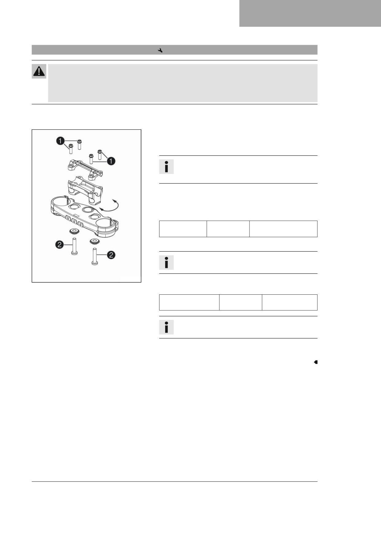
TUNING THE CHASSIS
11
11.15
Adjusting the handlebar position
Warning
Danger of accidents A repaired handlebar poses a safety risk.
If the handlebar is bent or straightened, the material becomes fatigued. The handlebar may break as a result.
- Change the handlebar if the handlebar is damaged or bent.
Preparatory work
- Take off the handlebar cushion.
Main work
- Remove screws 1. Take off the handlebar clamp. Take off the han-
dlebar and lay it to one side.
Info
Cover the components to protect them against damage.
Do not kink the cables or lines.
- Remove screws 2. Take off the handlebar support.
- Place the handlebar support in the required position. Mount and
tighten screws 2.
Guideline
Screw, handlebar
M10
40 Nm (29.5 lbf ft)
holder
Loctite®243™
– Position the handlebar.
Info
Make sure the cables and wiring are positioned correctly.
W00324-10
- Position the handlebar clamp. Mount screws 1 and tighten evenly.
Guideline
Screw, handlebar
M8
20 Nm (14.8 lbf ft)
clamp
Info
Make sure the installed gap widths are even.
Finishing work
- Mount the handlebar cushion.
49
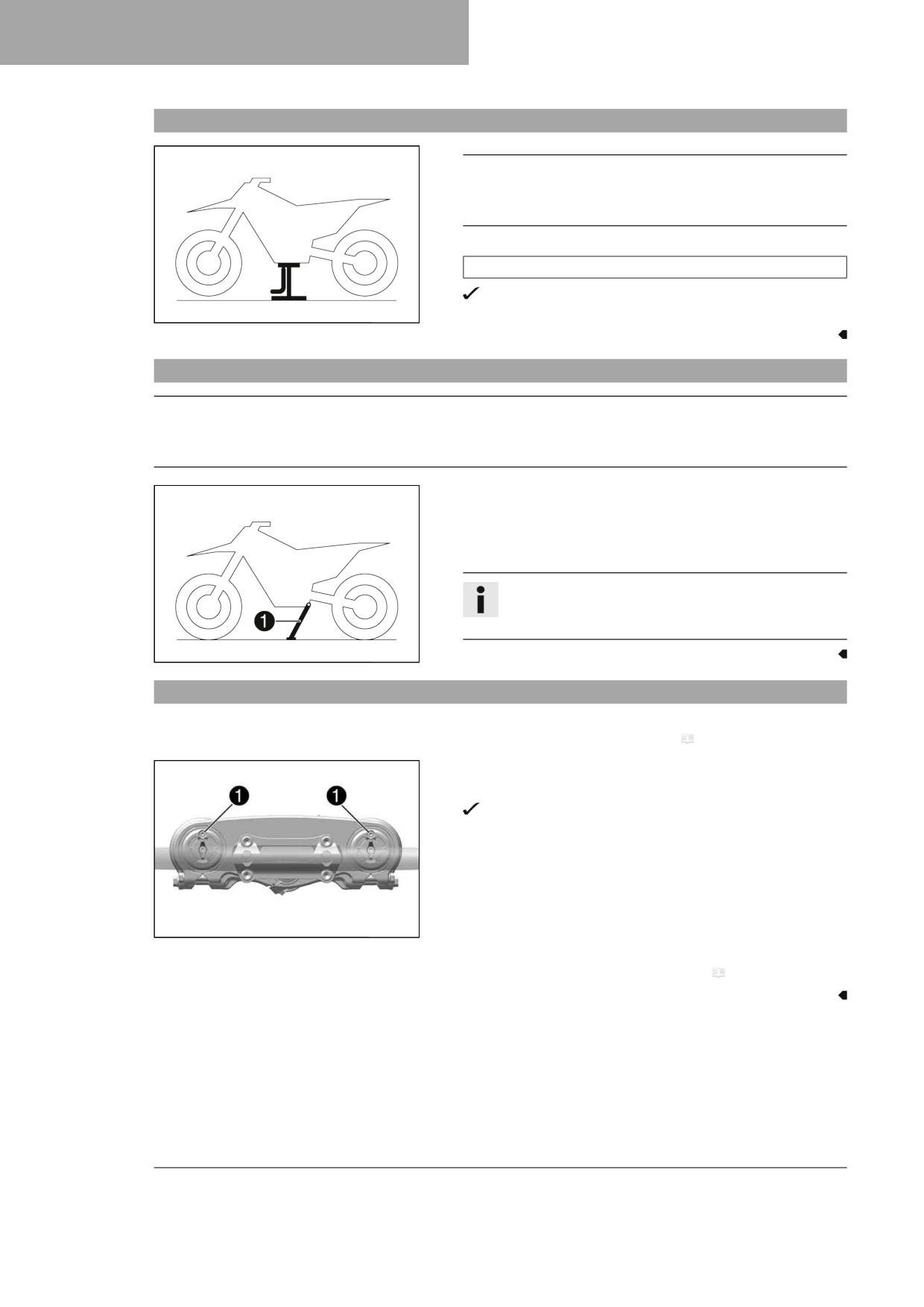
12
SERVICE WORK ON THE CHASSIS
12.1
Raising the motorcycle with a lift stand
Note
Danger of damage The parked vehicle can roll away or fall over.
- Park the vehicle on a firm and level surface.
- Raise the motorcycle at the frame underneath the engine.
Lift stand (A54029955100)
Neither wheel is in contact with the ground.
401942-01
- Secure the motorcycle against falling over.
12.2
Removing the motorcycle from the lift stand
Note
Danger of damage The parked vehicle can roll away or fall over.
- Park the vehicle on a firm and level surface.
- Remove the motorcycle from the lift stand.
- Remove the lift stand.
- To park the motorcycle, press side stand 1 to the ground with
your foot and lean the motorcycle on it.
Info
When you are riding, the side stand must be folded up and
secured with rubber strap.
401943-10
12.3
Bleeding the fork legs
Preparatory work
- Raise the motorcycle with a lift stand. ( p. 50)
Main work
- Release bleeder screws 1.
Any excess pressure escapes from the interior of the fork.
- Tighten the bleeder screws.
W00297-11
Finishing work
- Remove the motorcycle from the lift stand. ( p. 50)
50
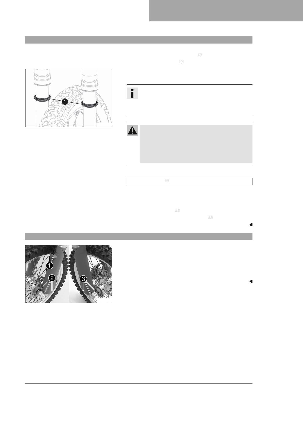
SERVICE WORK ON THE CHASSIS
12
12.4
Cleaning the dust boots of the fork legs
Preparatory work
- Raise the motorcycle with a lift stand. ( p. 50)
- Remove the fork protector. ( p. 51)
Main work
- Push dust boots 1 of both fork legs downward.
Info
The dust boots remove dust and coarse dirt particles from
the inside fork tubes. Over time, dirt can accumulate behind
the dust boots. If this dirt is not removed, the oil seals
behind can start to leak.
H03152-10
Warning
Danger of accidents Oil or grease on the brake discs
reduces the braking effect.
- Always keep the brake discs free of oil and grease.
- Clean the brake discs with brake cleaner when neces-
sary.
- Clean and oil the dust boots and inside fork tubes of both fork legs.
Universal oil spray ( p. 145)
- Press the dust boots back into the installation position.
- Remove the excess oil.
Finishing work
- Install the fork protector. ( p. 52)
- Remove the motorcycle from the lift stand. ( p. 50)
12.5
Removing the fork protector
- Remove screws 1 and take off the clamp.
- Remove screws 2 on the left fork leg and take off the left fork pro-
tector.
- Remove screws 3 on the right fork leg and take off the right fork
protector.
F03179-10
51
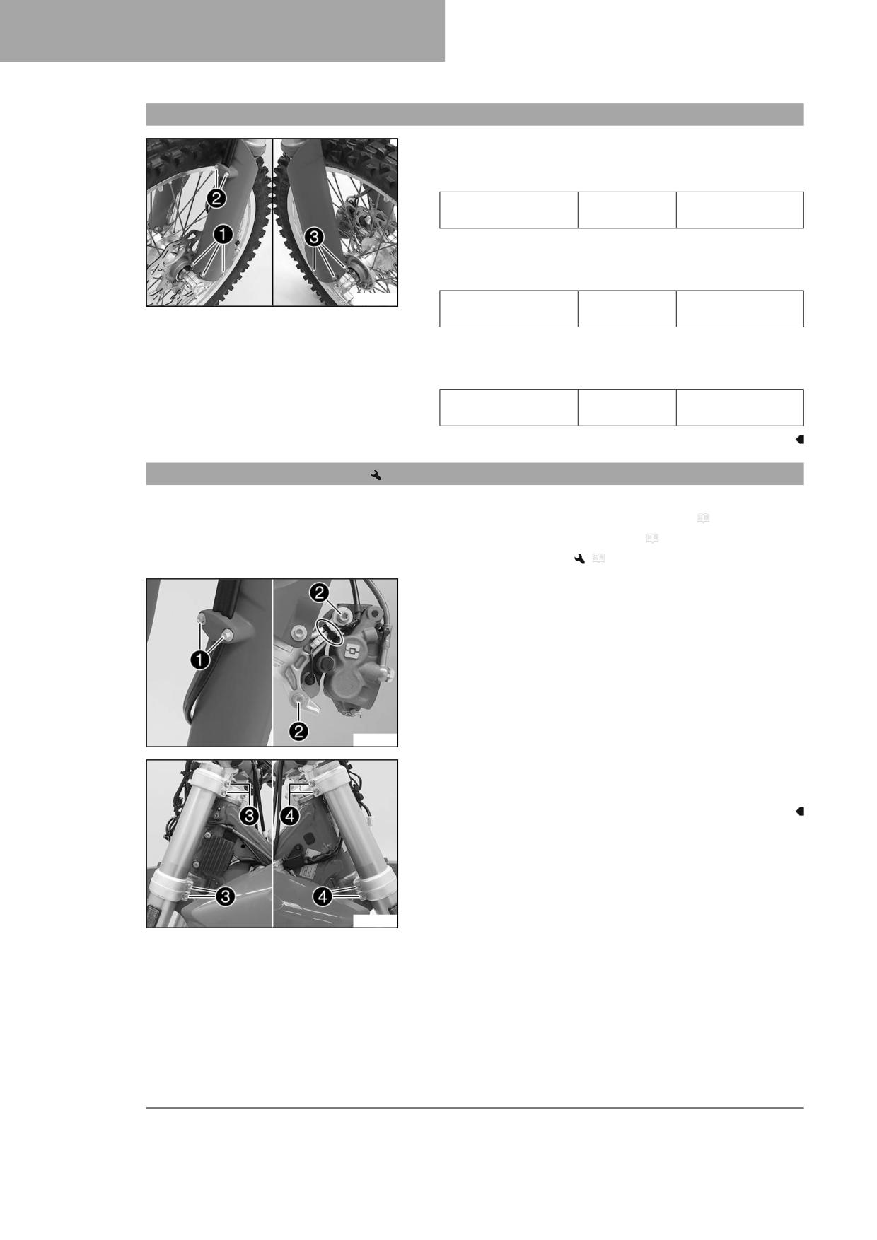
12
SERVICE WORK ON THE CHASSIS
12.6
Installing the fork protector
- Position the fork protector on left fork leg. Mount and tighten
screws 1.
Guideline
Remaining screws,
M6
10 Nm (7.4 lbf ft)
chassis
- Position the brake line, the wiring harness, and the clamp. Mount
and tighten screws 2.
Guideline
F03179-11
Screw, brake line
EJOT
1.7 Nm (1.25 lbf ft)
holder
- Position the fork protector on the right fork leg. Mount and tighten
screws 3.
Guideline
Remaining screws,
M6
10 Nm (7.4 lbf ft)
chassis
12.7
Removing the fork legs
Preparatory work
- Remove the headlight mask with the headlight. ( p. 105)
- Raise the motorcycle with a lift stand. ( p. 50)
- Remove the front wheel.
(
p. 95)
Main work
- Remove screws 1 and take off the clamp.
- Remove the cable ties.
- Remove screws 2 and take off the brake caliper.
- Allow the brake caliper and the brake line to hang loosely to the
side.
F03180-10
- Loosen screws 3. Remove the left fork leg.
- Loosen screws 4. Remove the right fork leg.
F03182-10
52
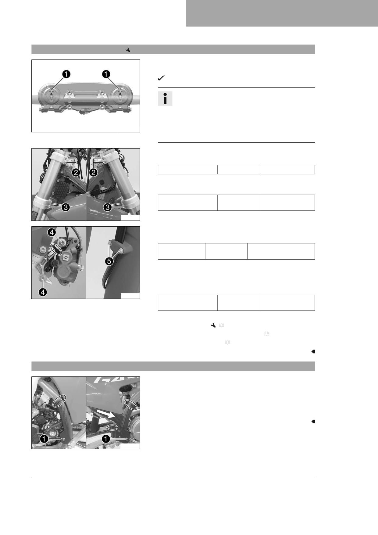
SERVICE WORK ON THE CHASSIS
12
12.8
Installing the fork legs
Main work
- Position the fork legs.
Bleeder screws 1 are positioned toward the front.
Info
The rebound damping is located in right fork leg REB (red
adjuster). The compression damping is located in left fork
leg COM (white adjuster).
Grooves are milled into the side of the upper end of the fork
W00297-11
legs. The second milled groove (from the top) must be flush
with the upper edge of the upper triple clamp.
- Tighten screws 2.
Guideline
Screw, top triple clamp
M8
20 Nm (14.8 lbf ft)
– Tighten screws 3.
Guideline
Screw, bottom triple
M8
15 Nm (11.1 lbf ft)
clamp
F03182-11
- Position the brake caliper, and mount and tighten screws 4.
Guideline
Screw, front
M8
25 Nm (18.4 lbf ft)
brake caliper
Loctite®243™
– Mount the cable ties.
- Position the brake line, the wiring harness, and the clamp. Mount
and tighten screws 5.
Guideline
F03181-10
Screw, brake line
EJOT
1.7 Nm (1.25 lbf ft)
holder
Finishing work
- Install the front wheel.
(
p. 96)
– Install the headlight mask with the headlight. ( p. 106)
- Check the headlight setting. ( p. 107)
12.9
Removing the frame protector
- Remove the cable ties.
- Remove screws 1 with the bushings.
- Take off the left frame protector.
- Push the right frame protector to the front and take off at the bot-
tom.
A01373-10
53
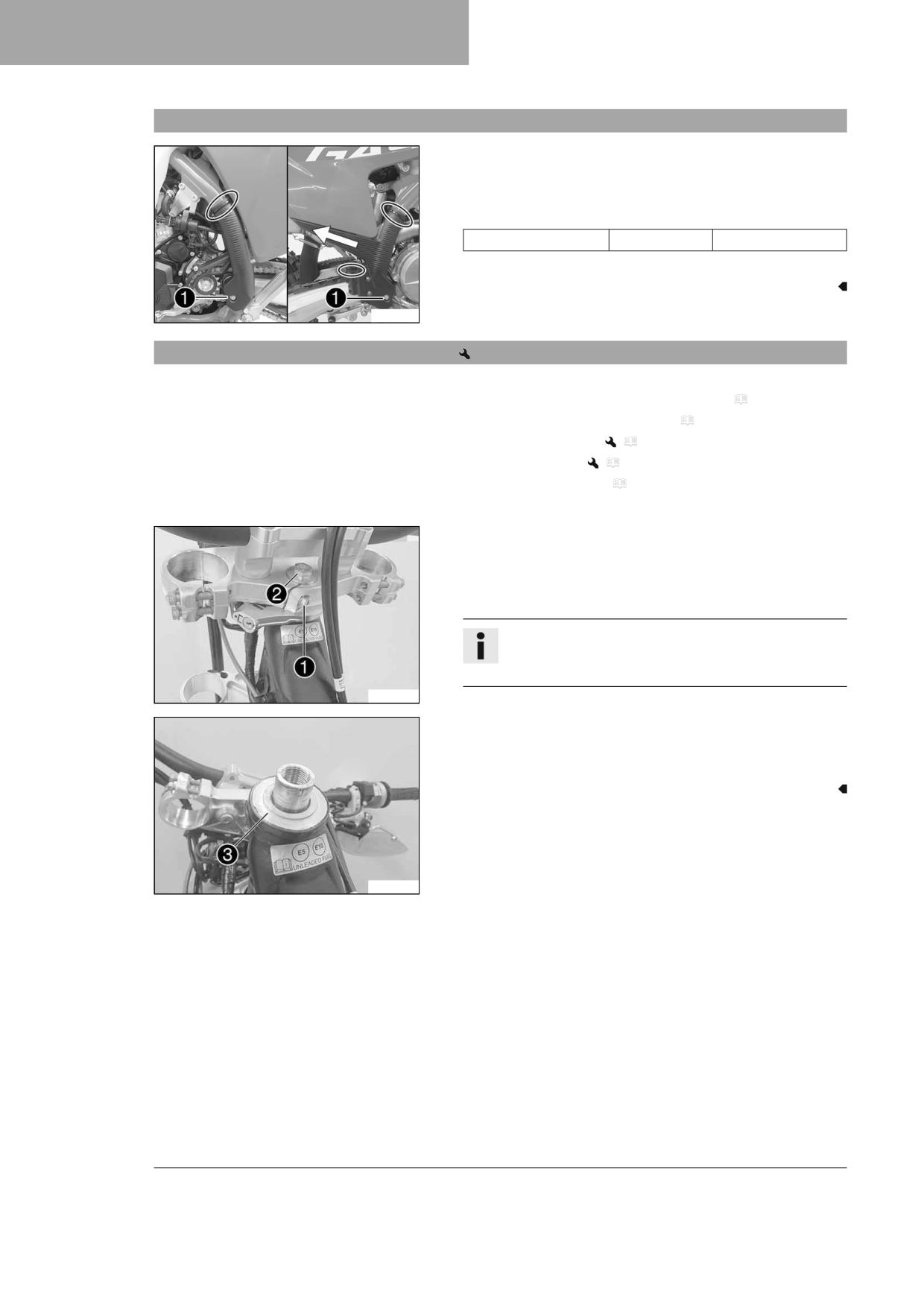
12
SERVICE WORK ON THE CHASSIS
12.10
Installing the frame protector
- Position the left frame protector.
- Insert the right frame protector from below and push it to the rear.
- Mount screws 1 with the bushings and tighten.
Guideline
Screw, frame protector
M5
3 Nm (2.2 lbf ft)
– Secure the frame protector with cable ties.
A01374-10
12.11
Removing the lower triple clamp
Preparatory work
- Remove the headlight mask with the headlight. ( p. 105)
- Raise the motorcycle with a lift stand. ( p. 50)
- Remove the front wheel.
(
p. 95)
– Remove the fork legs.
(
p. 52)
– Remove the front fender. ( p. 58)
- Take off the handlebar cushion.
Main work
- Remove screw 1.
- Remove screw 2.
- Take off the upper triple clamp with the handlebar and set it aside.
Info
Cover the components to protect them against damage.
Do not kink the cables or lines.
W00353-10
- Remove protective ring 3.
- Take off the lower triple clamp with the steering stem.
- Remove the upper steering head bearing.
W00354-10
54
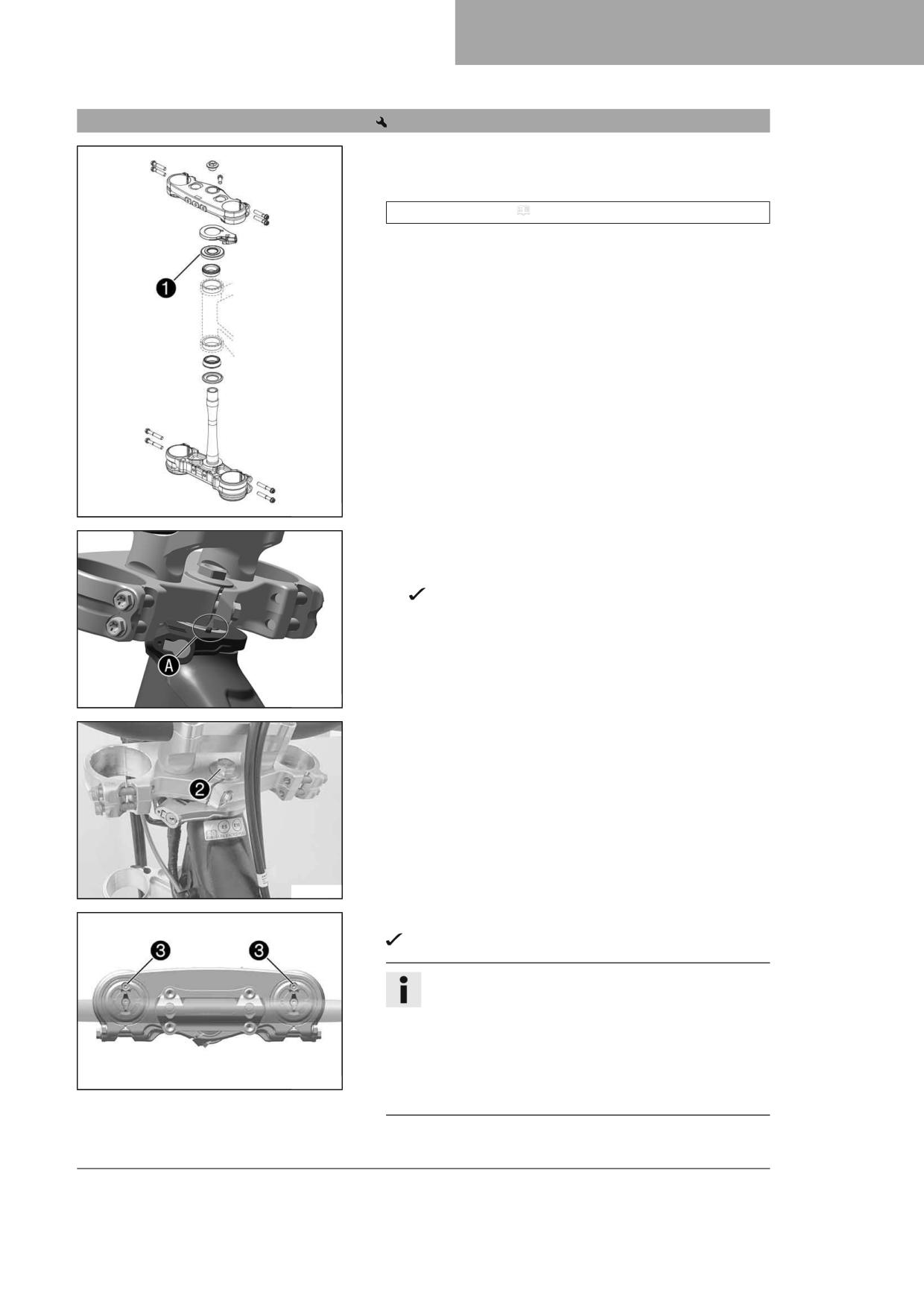
SERVICE WORK ON THE CHASSIS
12
12.12
Installing the lower triple clamp
Main work
- Clean the bearing and sealing elements, check for damage, and
grease.
High viscosity grease ( p. 144)
- Insert the lower triple clamp with the steering stem. Mount upper
steering head bearing.
- Push on protective ring 1.
W00319-11
(All EU models)
- Pay attention to the correct positioning of the steering lock in
area A.
The catch on the steering lock engages in the notch of the
triple clamp.
W00549-10
- Position the upper triple clamp and handlebar.
- Mount screw 2, but do not tighten it yet.
W00353-11
- Position the fork legs.
Bleeder screws 3 are positioned toward the front.
Info
The rebound damping is located in right fork leg REB (red
adjuster).
The compression damping is located in left fork leg COMP
(white adjuster).
Grooves are milled into the side of the upper end of the fork
W00297-13
legs. The second milled groove (from the top) must be flush
with the upper edge of the upper triple clamp.
55
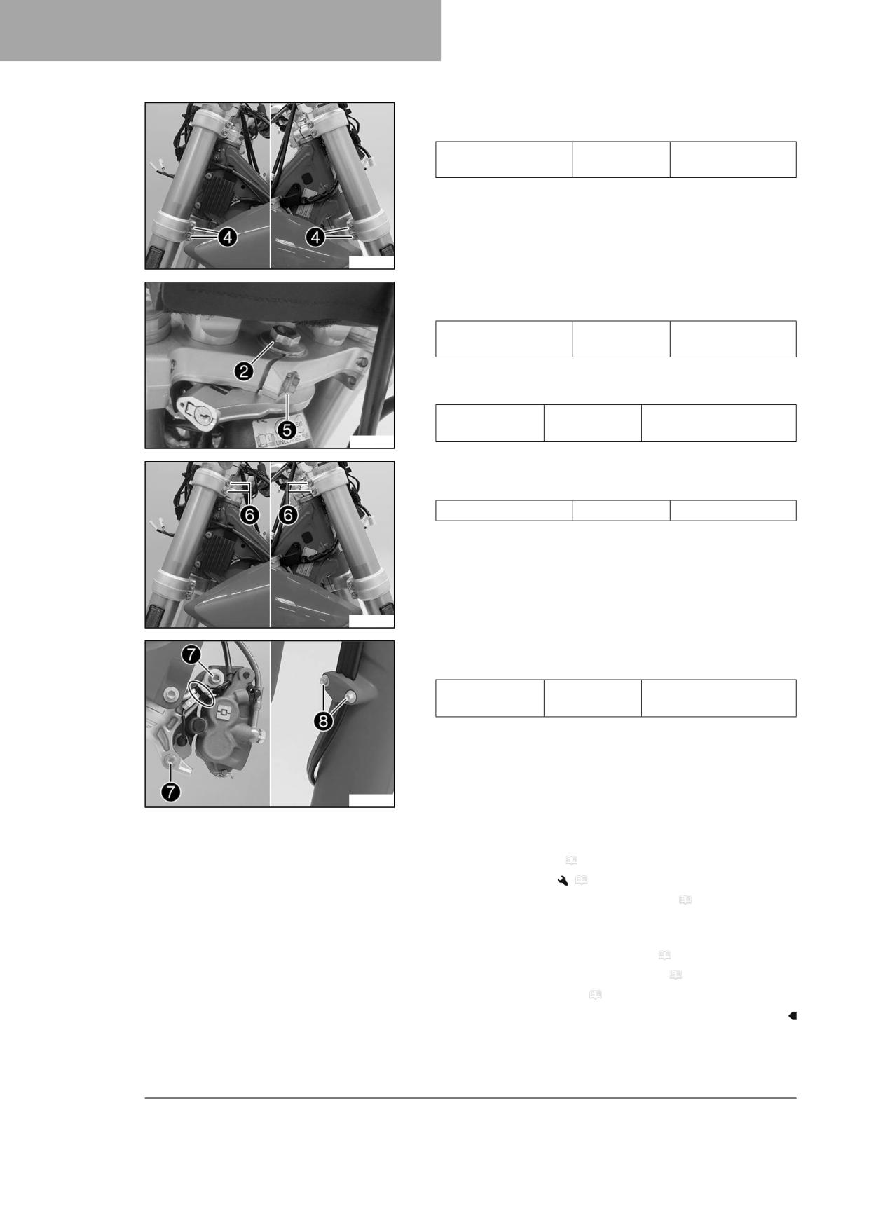
12
SERVICE WORK ON THE CHASSIS
- Tighten screws 4.
Guideline
Screw, bottom triple
M8
15 Nm (11.1 lbf ft)
clamp
A01357-10
- Tighten screw 2.
Guideline
Screw, top steering
M20x1.5
12 Nm (8.9 lbf ft)
head
- Mount and tighten screw 5.
Guideline
Screw, top steer-
M8
20 Nm (14.8 lbf ft)
ing stem
Loctite®243™
T04629-01
- Tighten screws 6.
Guideline
Screw, top triple clamp
M8
20 Nm (14.8 lbf ft)
A01359-10
- Position the brake caliper, and mount and tighten screws 7.
Guideline
Screw, front
M8
25 Nm (18.4 lbf ft)
brake caliper
Loctite®243™
– Mount the cable ties.
- Position the brake line, the wiring harness, and the clamp. Mount
and tighten screws 8.
A01360-10
Finishing work
- Mount the handlebar cushion.
- Install the front fender. ( p. 59)
- Install the front wheel.
(
p. 96)
– Install the headlight mask with the headlight. ( p. 106)
- Check the wiring harness, cables, and brake and clutch lines for free-
dom of movement and correct routing.
- Check the steering head bearing for play. ( p. 57)
- Remove the motorcycle from the lift stand. ( p. 50)
- Check the headlight setting. ( p. 107)
56
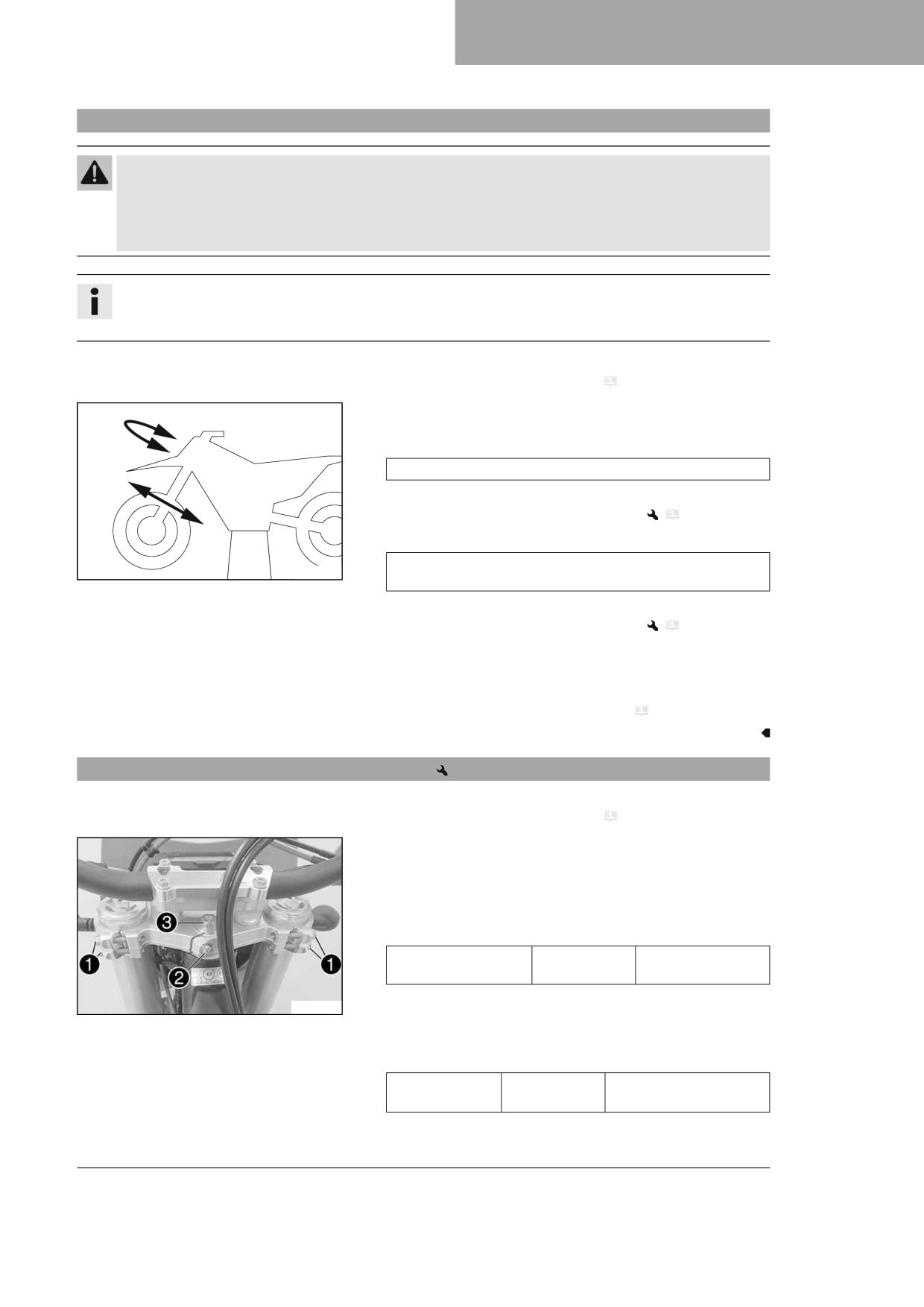
SERVICE WORK ON THE CHASSIS
12
12.13
Checking the steering head bearing play
Warning
Danger of accidents Incorrect steering head bearing play impairs the handling characteristic and damages com-
ponents.
- Correct incorrect steering head bearing play immediately. (Your authorized GASGAS Motorcycles workshop will
be glad to help.)
Info
If the vehicle is operated for a lengthy period with play in the steering head bearing, the bearings and the bearing
seats in the frame can become damaged over time.
Preparatory work
- Raise the motorcycle with a lift stand. ( p. 50)
Main work
- Move the handlebar to the straight-ahead position. Move the fork
legs to and fro in the direction of travel.
Play should not be detectable on the steering head bearing.
» If there is detectable play:
- Adjust the steering head bearing play.
(
p. 57)
– Move the handlebar to and fro over the entire steering range.
It must be possible to move the handlebar easily over the entire
H01167-01
steering range. There should be no detectable detent positions.
» If detent positions are detected:
- Adjust the steering head bearing play.
(
p. 57)
– Check the steering head bearing and replace if necessary.
- Check the steering stop bolts for correct adjustment and locking.
Finishing work
- Remove the motorcycle from the lift stand. ( p. 50)
12.14
Adjusting the steering head bearing play
Preparatory work
- Raise the motorcycle with a lift stand. ( p. 50)
Main work
- Loosen screws 1.
- Remove screw 2.
- Loosen and retighten screw 3.
Guideline
Screw, top steering
M20x1.5
12 Nm (8.9 lbf ft)
head
- Using a plastic hammer, tap lightly on the upper triple clamp to
W00339-10
avoid stresses.
- Mount and tighten screw 2.
Guideline
Screw, top steer-
M8
20 Nm (14.8 lbf ft)
ing stem
Loctite®243™
– Tighten screws 1.
57
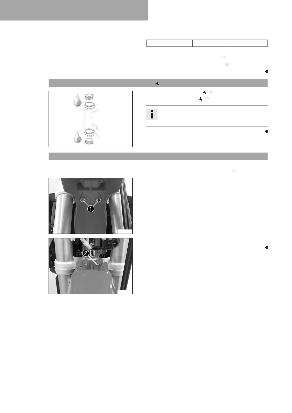
12
SERVICE WORK ON THE CHASSIS
Guideline
Screw, top triple clamp
M8
20 Nm (14.8 lbf ft)
Finishing work
- Check the steering head bearing for play. ( p. 57)
- Remove the motorcycle from the lift stand. ( p. 50)
12.15
Lubricating the steering head bearing
- Remove the lower triple clamp.
(
p. 54)
– Install the lower triple clamp.
(
p. 55)
Info
The steering head bearing is cleaned and lubricated in the
course of removal and installation of the lower triple clamp.
H02387-01
12.16
Removing the front fender
Preparatory work
- Remove the headlight mask with the headlight. ( p. 105)
Main work
- Remove screws 1.
F03187-10
- Remove screws 2. Take off the front fender.
F03188-10
58
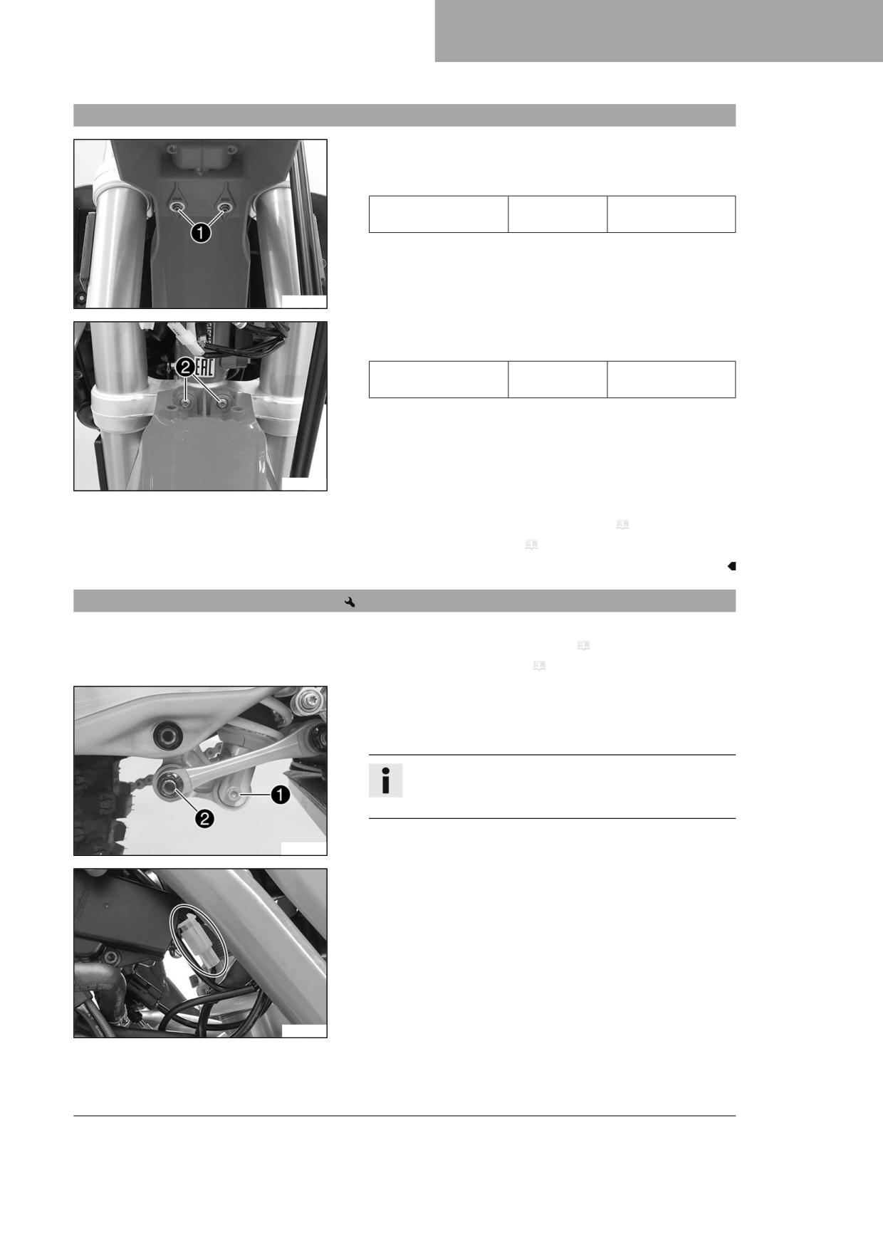
SERVICE WORK ON THE CHASSIS
12
12.17
Installing the front fender
Main work
- Position the front fender. Mount and tighten screws 1.
Guideline
Remaining screws,
M6
10 Nm (7.4 lbf ft)
chassis
F03187-10
- Mount and tighten screws 2.
Guideline
Remaining screws,
M6
10 Nm (7.4 lbf ft)
chassis
F03188-10
Finishing work
- Install the headlight mask with the headlight. ( p. 106)
- Check the headlight setting. ( p. 107)
12.18
Removing the shock absorber
Preparatory work
- Raise the motorcycle with a lift stand. ( p. 50)
- Remove the frame protector. ( p. 53)
Main work
- Remove screw 1.
- Remove fitting 2.
Info
Raise the link fork slightly to be able to remove the screws
more easily.
A01376-10
- Disconnect the plug-in connector of the brake light switch.
F03193-10
59
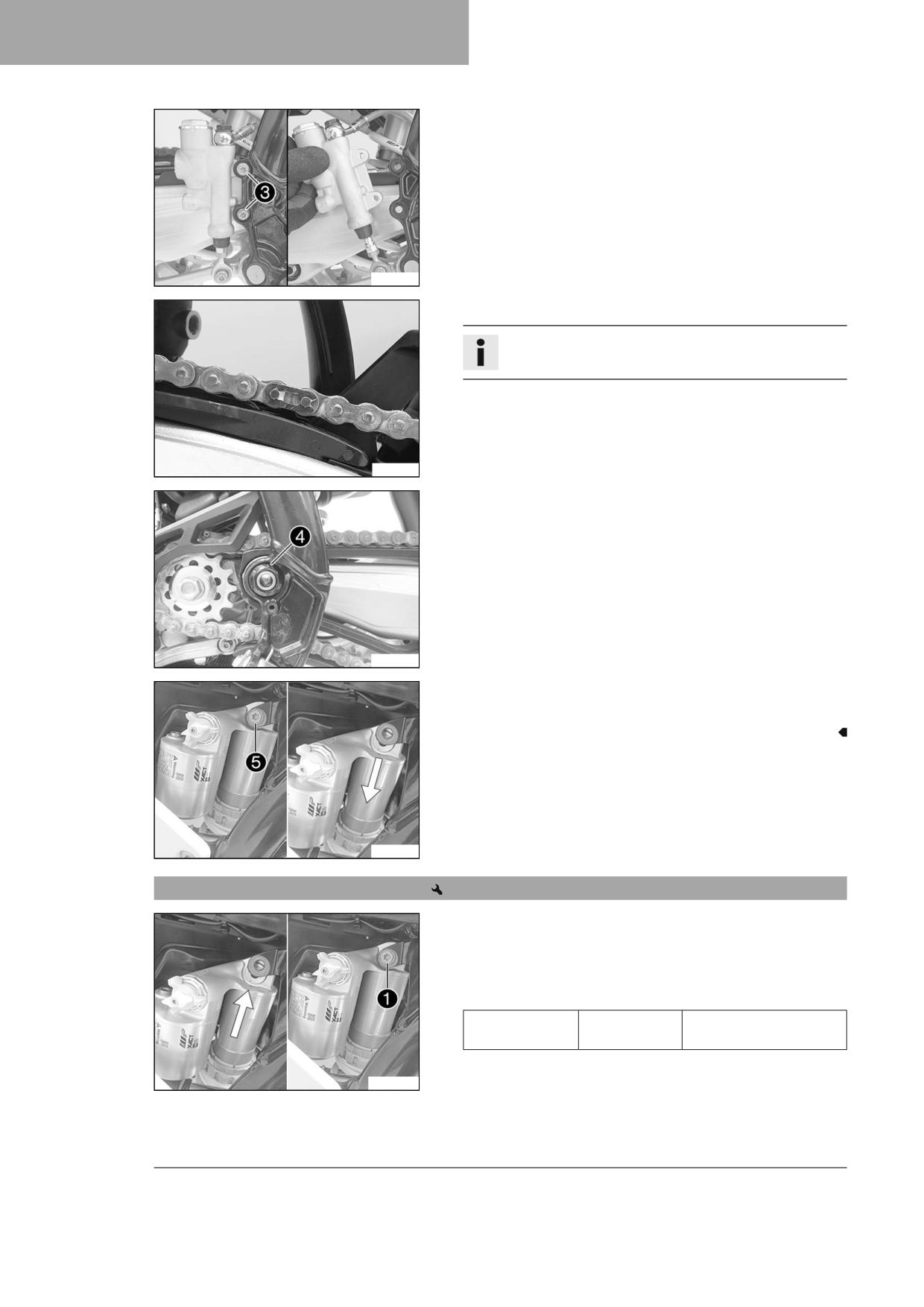
12
SERVICE WORK ON THE CHASSIS
- Remove screws 3.
- Pull off rear brake cylinder from the push rod.
A01377-10
- Remove the connecting link on the chain.
Info
Cover the components to protect them against damage.
- Take off the chain.
F03196-01
- Remove nut 4 and pull out the swingarm pivot.
- Push the link fork back and secure it against falling over.
A01378-10
- Hold the shock absorber and remove screw 5.
- Remove the shock absorber carefully at the bottom.
A01379-10
12.19
Installing the shock absorber
Main work
- Carefully position the shock absorber into the vehicle from the bot-
tom.
- Mount and tighten screw 1.
Guideline
Screw, top shock
M12
80 Nm (59 lbf ft)
absorber
Loctite®2701™
W00056-10
60
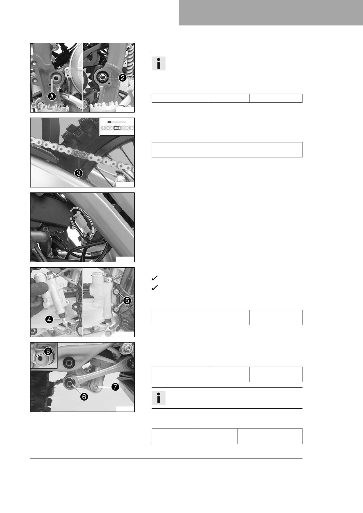
SERVICE WORK ON THE CHASSIS
12
– Position the link fork and mount the swingarm pivot.
Info
Pay attention to flat area A.
- Mount and tighten nut 2.
Guideline
Nut, fork pivot
M16x1.5
100 Nm (73.8 lbf ft)
F03198-10
- Mount the chain.
- Connect the chain with connecting link 3.
Guideline
The closed side of the chain joint lock must face in the direction
of travel.
F03702-12
- Join plug-in connector of the brake light switch.
F03193-10
- Position the rear brake cylinder.
Push rod 4 engages in the rear brake cylinder.
The dust boot is correctly positioned.
- Mount and tighten screws 5.
Guideline
Remaining screws,
M6
10 Nm (7.4 lbf ft)
chassis
W00052-10
- Position the angle lever and linkage lever.
- Mount and tighten fitting 6.
Guideline
Nut, linkage lever on
M16x1.5
80 Nm (59 lbf ft)
angle lever
Info
Pay attention to flat area B.
S05741-10
- Mount and tighten screw 7.
Guideline
Screw, bottom
M12
80 Nm (59 lbf ft)
shock absorber
Loctite®2701™
61
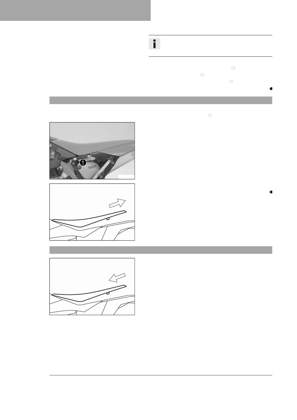
12
SERVICE WORK ON THE CHASSIS
Info
Raise the link fork slightly to be able to mount the screw
more easily.
Finishing work
- Check the free travel of the foot brake lever. ( p. 89)
- Install the frame protector. ( p. 54)
- Remove the motorcycle from the lift stand. ( p. 50)
12.20
Removing the seat
Preparatory work
- Remove the air filter box cover. ( p. 63)
Main work
- Remove screw 1 with the wedge lock washers.
W00439-10
- Raise the rear of the seat, pull the seat back and lift it off.
H02218-10
12.21
Mounting the seat
Main work
- Mount the front of the seat on the collar bushings of the fuel tank,
lower the seat at the rear, and push the seat forward.
- Make sure the seat is latched in place correctly.
H02218-11
62
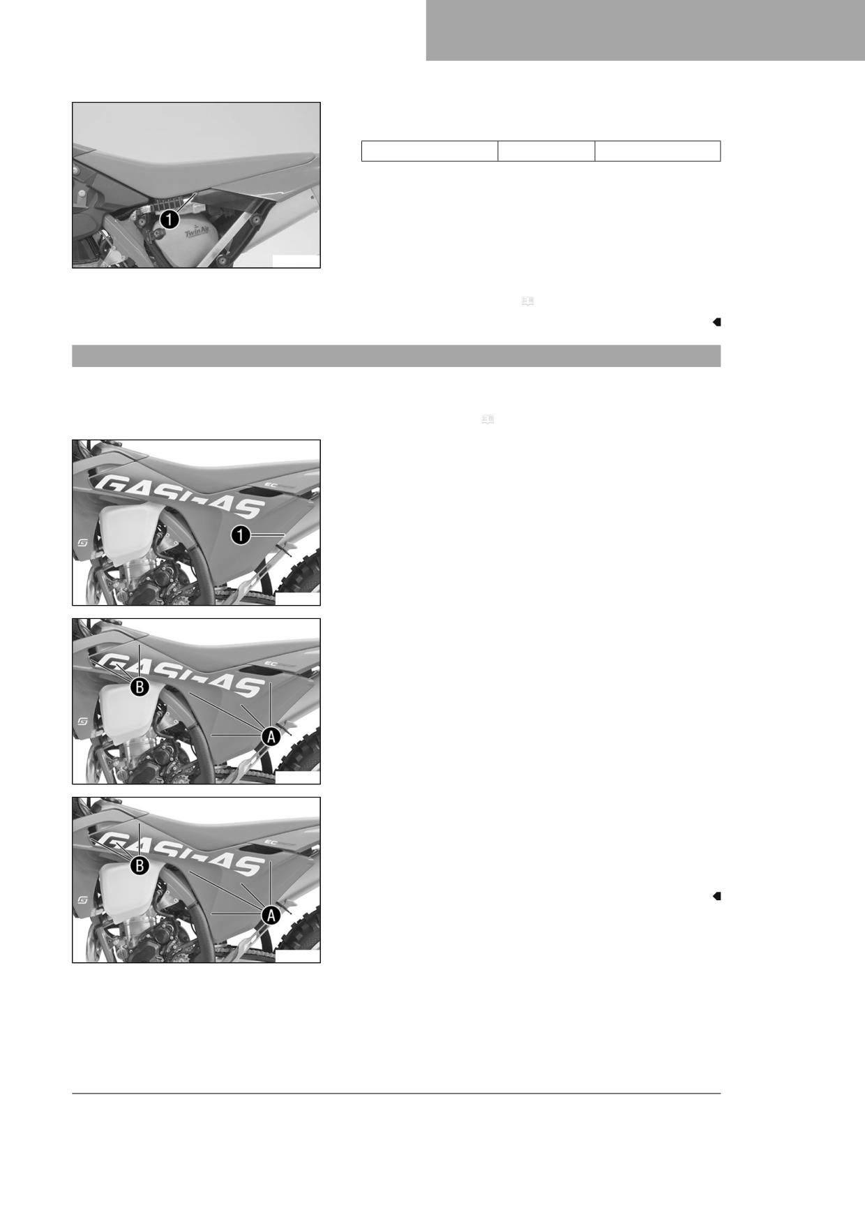
SERVICE WORK ON THE CHASSIS
12
– Mount and tighten screw 1 and wedge lock washers.
Guideline
Screw, rear seat fixing
M6
6 Nm (4.4 lbf ft)
W00439-10
Finishing work
- Install the air filter box cover. ( p. 64)
12.22
Removing the air filter box cover
Condition
The air filter box cover is secured.
- Remove the seat. ( p. 62)
- Remove screw 1.
A01328-10
- Detach the air filter box cover in area A and slide it in area B
to the rear.
- Take off the air filter box cover.
A01329-10
Condition
The air filter box cover is not secured.
- Detach the air filter box cover in area A and slide it in area B
to the rear.
- Take off the air filter box cover.
A01329-10
63
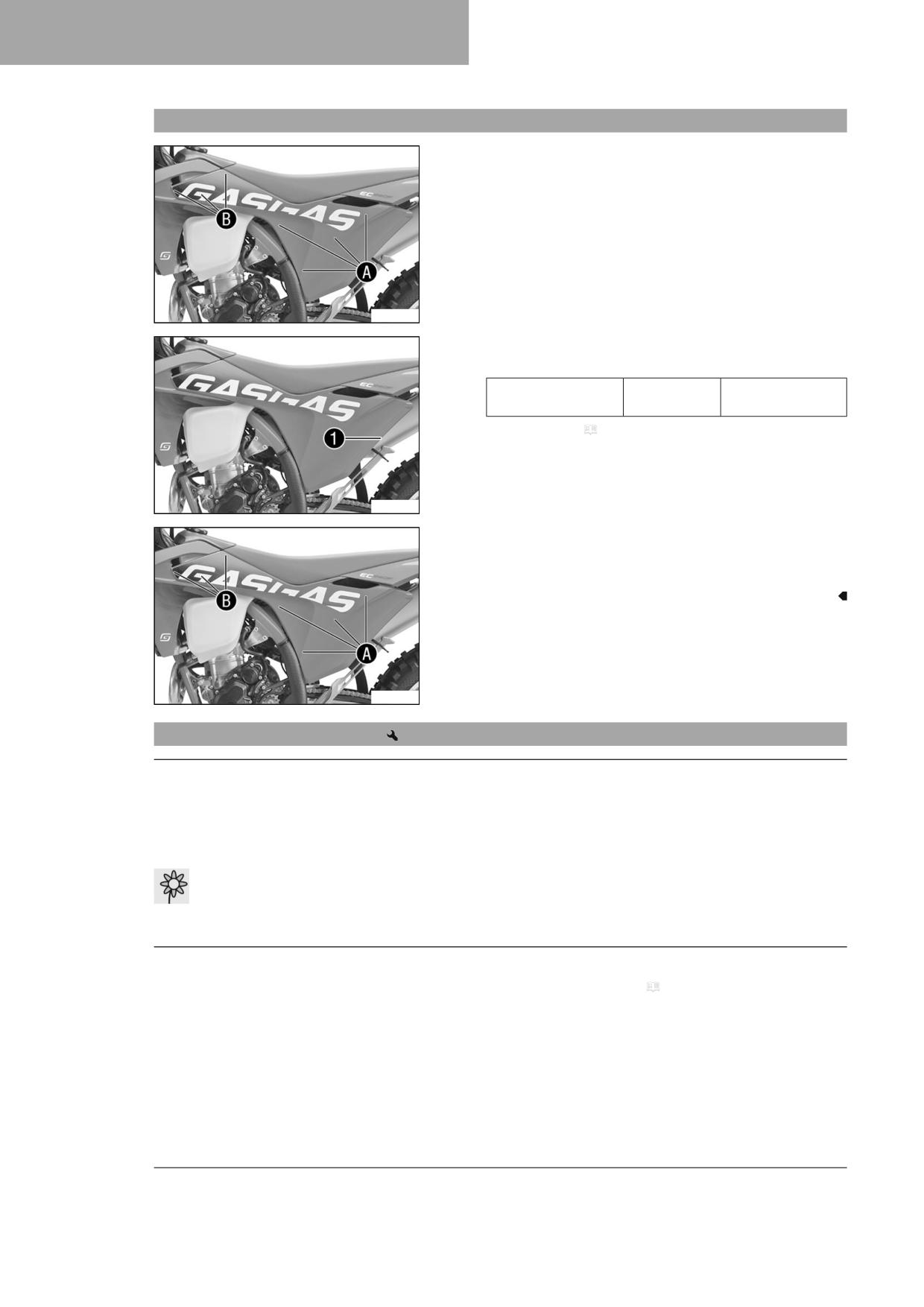
12
SERVICE WORK ON THE CHASSIS
12.23
Installing the air filter box cover
Condition
The air filter box cover is secured.
- Insert the air filter box cover in area B and clip it into area A.
A01329-10
- Mount and tighten screw 1.
Guideline
Screw, air filter box
EJOT PT®
3 Nm (2.2 lbf ft)
cover
K60x20-Z
– Mount the seat. ( p. 62)
A01328-10
Condition
The air filter box cover is not secured.
- Insert the air filter box cover in area B and clip it into area A.
A01329-10
12.24
Removing the air filter
Note
Engine damage Unfiltered intake air has a negative effect on the service life of the engine.
Dust and dirt will enter the engine without an air filter.
- Only operate the vehicle if it is equipped with an air filter.
Note
Environmental hazard Hazardous substances cause environmental damage.
- Dispose of oils, grease, filters, fuel, cleaning agents, brake fluid, etc., correctly and in compliance with the appli-
cable regulations.
Preparatory work
- Remove the air filter box cover. ( p. 63)
64
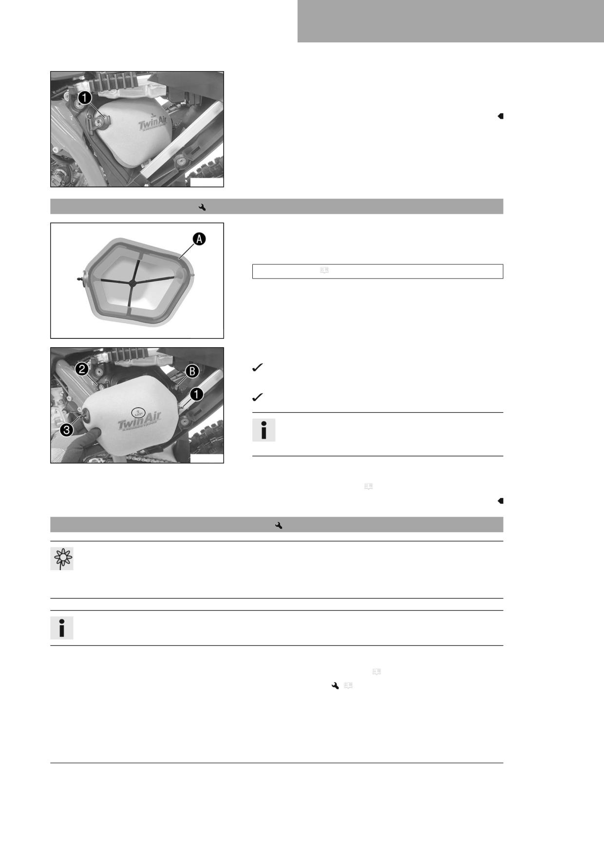
SERVICE WORK ON THE CHASSIS
12
Main work
- Detach retaining tab 1. Remove air filter with air filter support.
- Remove air filter from air filter support.
W00216-10
12.25
Installing the air filter
Main work
- Mount the clean air filter on the air filter support.
- Grease the air filter in area A.
Long-life grease ( p. 144)
W00457-10
- Insert air filter and position retaining pin 1 in bushing B.
The air filter is correctly positioned.
- Insert retaining tab 2.
Retaining pin 3 is secured by retaining tab 2.
Info
If the air filter is not mounted correctly, dust and dirt may
enter the engine and result in damage.
W00217-10
Finishing work
- Install the air filter box cover. ( p. 64)
12.26
Cleaning the air filter and air filter box
Note
Environmental hazard Hazardous substances cause environmental damage.
- Dispose of oils, grease, filters, fuel, cleaning agents, brake fluid, etc., correctly and in compliance with the appli-
cable regulations.
Info
Do not clean the air filter with fuel or petroleum since these substances attack the foam.
Preparatory work
- Remove the air filter box cover. ( p. 63)
- Remove the air filter.
(
p. 64)
65
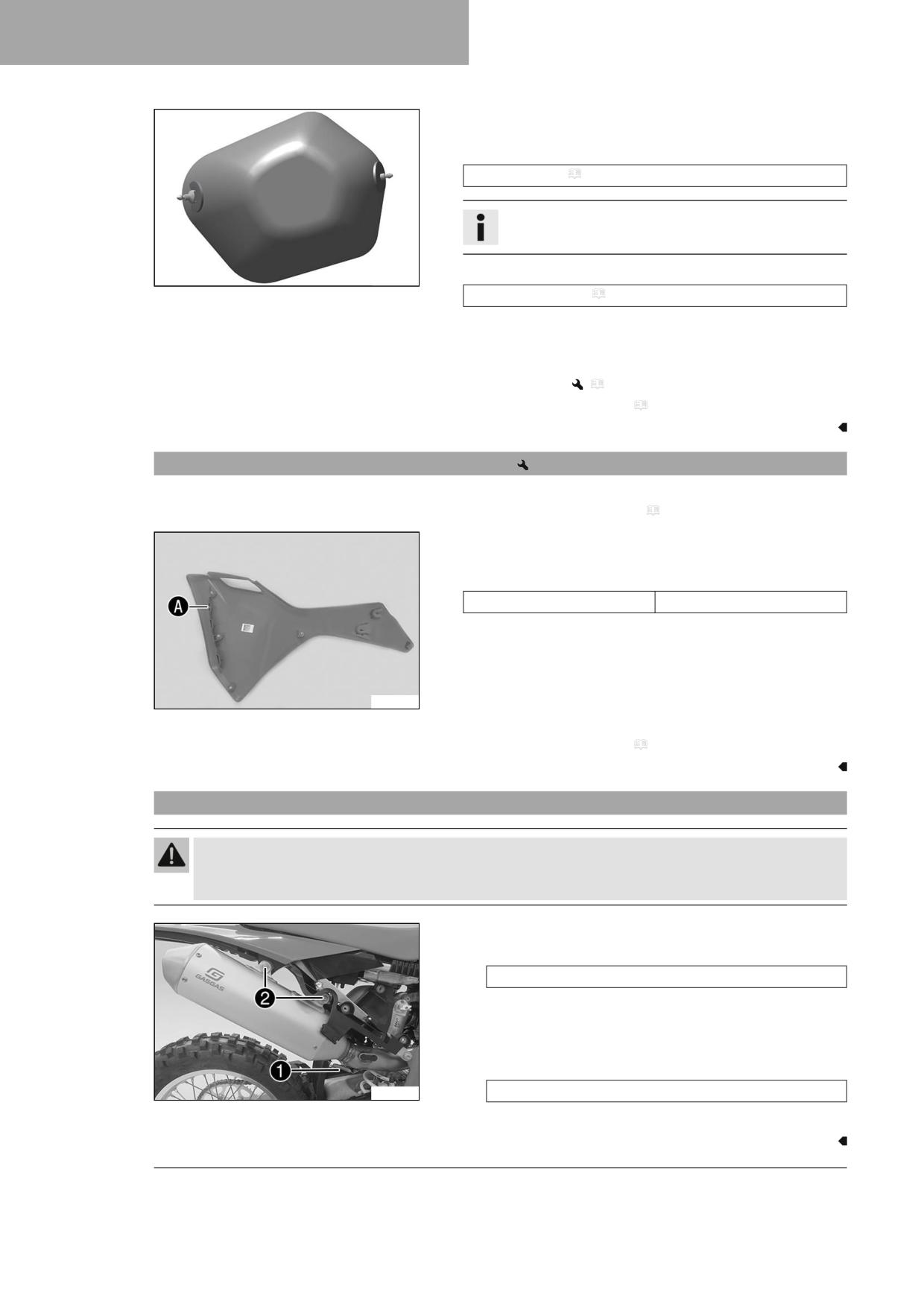
12
SERVICE WORK ON THE CHASSIS
Main work
- Wash the air filter thoroughly in special cleaning liquid and allow it
to dry properly.
Air filter cleaner ( p. 144)
Info
Only press the air filter to dry it, never wring it out.
- Oil the dry air filter with a high-grade air filter oil.
F03685-01
Oil for foam air filter ( p. 144)
- Clean the air filter box.
- Check the intake flange for damage and looseness.
Finishing work
- Install the air filter.
(
p. 65)
– Install the air filter box cover. ( p. 64)
12.27
Preparing air filter box cover for securing
Preparatory work
- Remove the air filter box cover. ( p. 63)
Main work
- Drill a hole at marking A.
Guideline
Diameter
6 mm (0.24 in)
A01375-10
Finishing work
- Install the air filter box cover. ( p. 64)
12.28
Removing the main silencer
Warning
Danger of burns The exhaust system gets hot when the vehicle is driven.
- Allow the exhaust system to cool down before performing any work on the vehicle.
(All EU models)
- Detach spring 1.
Spring hook (50305017000C1)
- Remove screws 2 and take off the main silencer with the cat-
alytic converter.
(All US models)
- Detach spring 1.
A01330-10
Spring hook (50305017000C1)
- Remove screws 2 and take off the main silencer.
66
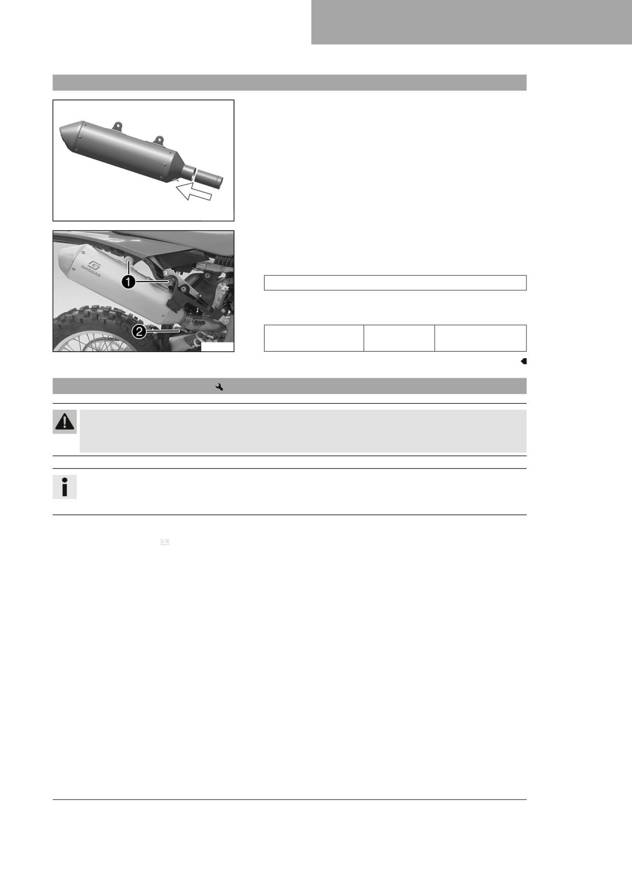
SERVICE WORK ON THE CHASSIS
12
12.29
Installing the main silencer
(All EU models)
- Position the catalytic converter in the main silencer.
S02101-10
- Position the main silencer. Mount screws 1 with washers, but do
not tighten yet.
- Attach spring 2.
Spring hook (50305017000C1)
- Tighten screws 1.
Guideline
Remaining screws,
M6
10 Nm (7.4 lbf ft)
chassis
A01331-10
12.30
Cleaning spark arrestor (EW 500F US)
Warning
Danger of burns The exhaust system gets hot when the vehicle is driven.
- Allow the exhaust system to cool down before performing any work on the vehicle.
Info
Soot particles accumulate on the screen of the spark arrestor over time.
This changes the performance characteristics.
Preparatory work
- Remove main silencer. ( p. 66)
67
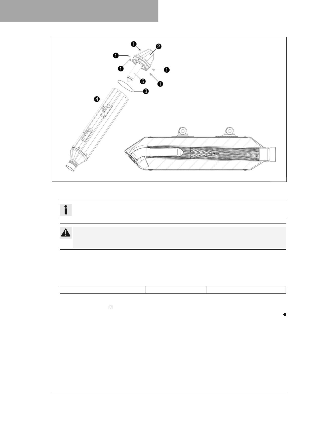
12
SERVICE WORK ON THE CHASSIS
H01763-10
Main work
- Remove screws 1 and take off silencer cap 2 with O-ring 3.
Info
Do not remove the glass fiber yarn filling.
Caution
Danger to health Soot particles irritate the eyes and mucuous membranes.
- Wear suitable breathing and eye protection when cleaning the main silencer and carbon screen.
- Clean main silencer sleeve 4 and screen 5 of the spark arrestor with compressed air.
- Mount new O-ring 3 on silencer cap 2.
- Position silencer cap 2. Mount and tighten screws 1.
Guideline
Screws on main silencer
M5
7 Nm (5.2 lbf ft)
Finishing work
- Install the main silencer. ( p. 67)
68
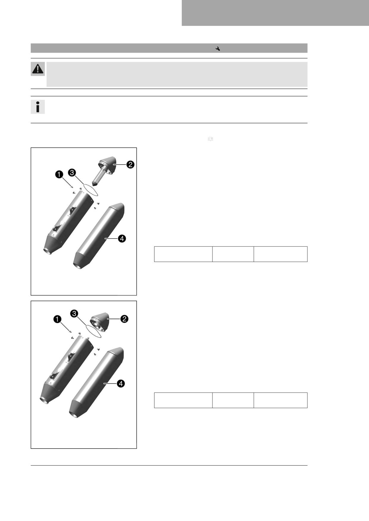
SERVICE WORK ON THE CHASSIS
12
12.31
Changing the glass fiber yarn filling in the main silencer
Warning
Danger of burns The exhaust system gets hot when the vehicle is driven.
- Allow the exhaust system to cool down before performing any work on the vehicle.
Info
Over time, the fibers of the glass fiber yarn filling escape and the damper "burns" out.
Not only is the noise level higher, but the performance characteristics change.
Preparatory work
- Remove main silencer. ( p. 66)
Main work
(EW 500F US)
- Remove screws 1.
- Take off silencer cap 2 with O-ring 3.
- Remove the old glass fiber yarn filling.
- Clean the parts that need to be reinstalled and check for dam-
age.
- Fit new glass fiber yarn filling 4 into the main silencer.
- Mount the O-ring on the silencer cap.
- Position the silencer cap.
- Mount and tighten all of the screws.
Guideline
Screws on main
M5
7 Nm (5.2 lbf ft)
silencer
V01735-10
(All EC models)
- Remove screws 1.
- Take off silencer cap 2 with O-ring 3.
- Remove the old glass fiber yarn filling.
- Clean the parts that need to be reinstalled and check for dam-
age.
- Fit new glass fiber yarn filling 4 into the main silencer.
- Mount the O-ring on the silencer cap.
- Position the silencer cap.
- Mount and tighten all of the screws.
Guideline
Screws on main
M5
7 Nm (5.2 lbf ft)
silencer
V01734-10
69
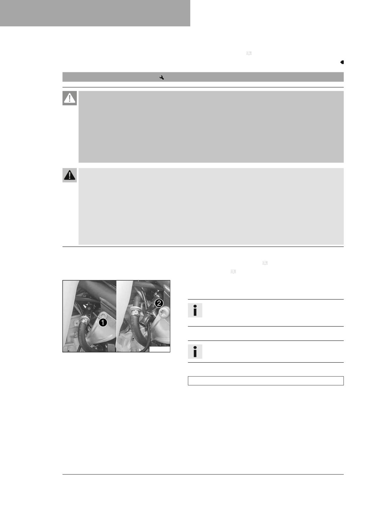
12
SERVICE WORK ON THE CHASSIS
Finishing work
- Install the main silencer. ( p. 67)
12.32
Removing the fuel tank
Danger
Fire hazard Fuel is highly flammable.
The fuel in the fuel tank expands when warm and can escape if overfilled.
- Do not fuel the vehicle in the vicinity of open flames or lit cigarettes.
- Switch off the engine for refueling.
- Make sure that no fuel is spilled; particularly not on hot parts of the vehicle.
- If any fuel is spilled, wipe it off immediately.
- Observe the specifications for refueling.
Warning
Danger of poisoning Fuel is harmful to health.
- Avoid skin, eye and clothing contact with fuel.
- Immediately consult a doctor if you swallow fuel.
- Do not inhale fuel vapors.
- Rinse the affected area immediately with plenty of water in the event of contact with the skin.
- Rinse the eyes thoroughly with water, and consult a doctor in case of fuel contact with the eyes.
- Change your clothing if fuel spills on them.
- Keep fuels correctly in a suitable canister, and out of the reach of children.
Preparatory work
- Remove the air filter box cover. ( p. 63)
- Remove the seat. ( p. 62)
Main work
- Clean quick release coupling 1 thoroughly with compressed air.
Info
Under no circumstances should dirt enter into the fuel line.
Dirt in the fuel line clogs the injection valve!
- Disconnect the quick release coupling.
W00346-10
Info
Remaining fuel may flow out of the fuel line.
- Mount wash cap set 2.
Wash cap set (81212016100)
70
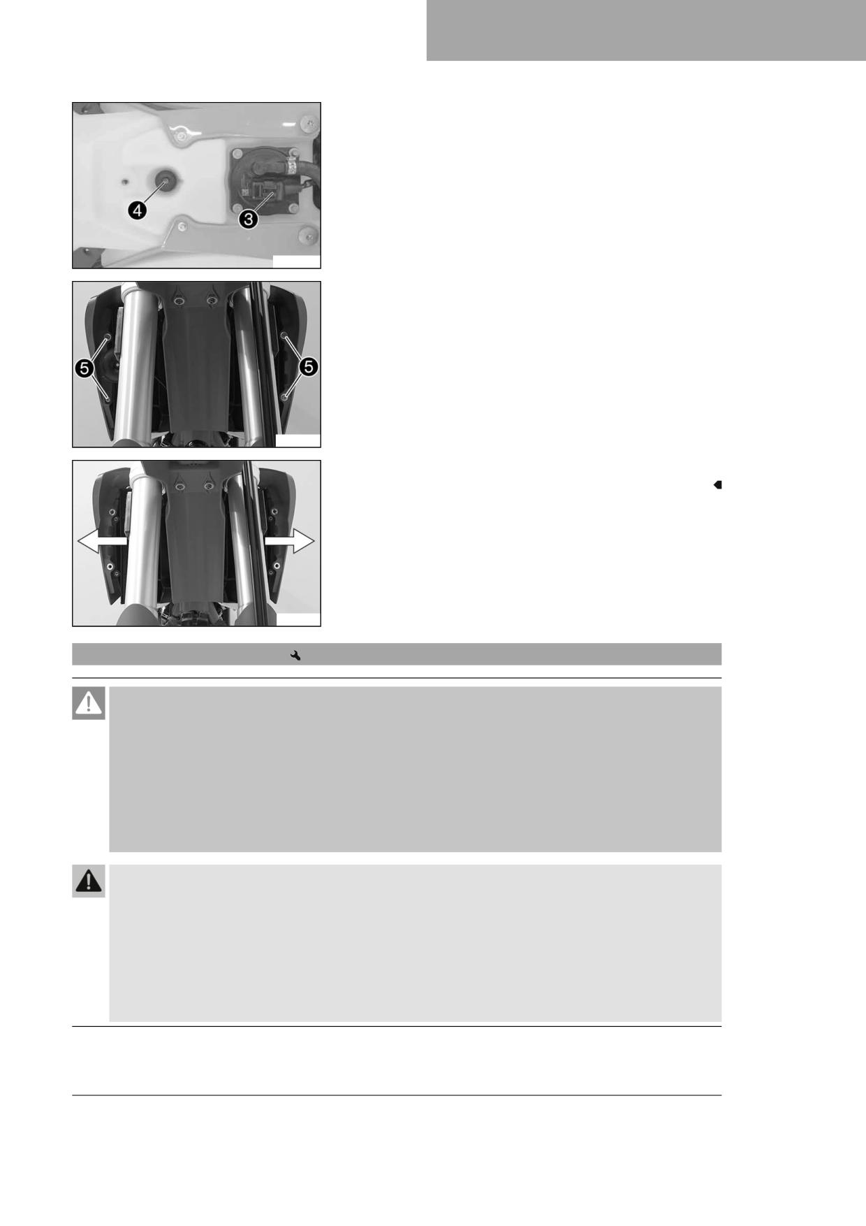
SERVICE WORK ON THE CHASSIS
12
– Unplug fuel pump connector 3.
- Remove screw 4 with the rubber bushing.
W00342-10
- Remove screws 5.
- Hang the horn and horn bracket to one side.
A01349-10
- Pull both spoilers laterally off the radiator and lift off the fuel tank.
F03212-10
12.33
Installing the fuel tank
Danger
Fire hazard Fuel is highly flammable.
The fuel in the fuel tank expands when warm and can escape if overfilled.
- Do not fuel the vehicle in the vicinity of open flames or lit cigarettes.
- Switch off the engine for refueling.
- Make sure that no fuel is spilled; particularly not on hot parts of the vehicle.
- If any fuel is spilled, wipe it off immediately.
- Observe the specifications for refueling.
Warning
Danger of poisoning Fuel is harmful to health.
- Avoid skin, eye and clothing contact with fuel.
- Immediately consult a doctor if you swallow fuel.
- Do not inhale fuel vapors.
- Rinse the affected area immediately with plenty of water in the event of contact with the skin.
- Rinse the eyes thoroughly with water, and consult a doctor in case of fuel contact with the eyes.
- Change your clothing if fuel spills on them.
71
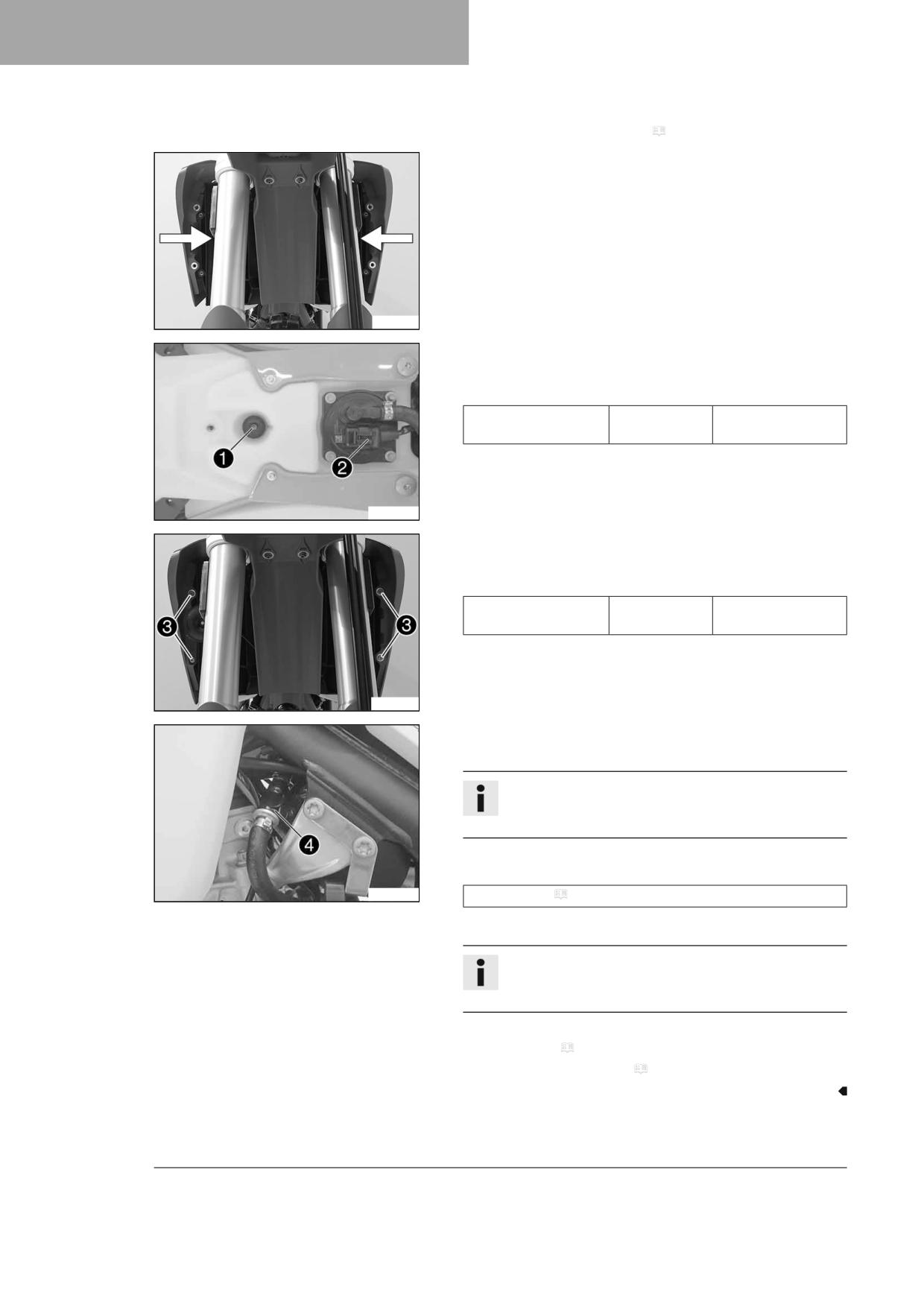
12
SERVICE WORK ON THE CHASSIS
Main work
- Check the throttle cable routing. ( p. 78)
- Position the fuel tank and fit the two spoilers to the sides in front of
the radiator bracket.
- Make sure that no cables or throttle cables are trapped or damaged.
F03212-11
- Attach the fuel tank breather hose.
- Mount and tighten screw 1 with the rubber bushing.
Guideline
Remaining screws,
M6
10 Nm (7.4 lbf ft)
chassis
- Plug in fuel pump connector 2.
W00342-11
- Position the horn with the horn bracket.
- Mount and tighten screws 3.
Guideline
Screw, fuel tank spoiler
M6
6 Nm (4.4 lbf ft)
on radiator
A01350-10
- Remove the wash cap set.
- Clean the quick release coupling thoroughly with compressed air.
Info
Under no circumstances should dirt enter into the fuel line.
Dirt in the fuel line clogs the injection valve!
- Spray silicone spray onto a lint-free cleaning cloth and lightly lubri-
cate the O-ring of the quick-release coupling.
W00348-10
Silicone spray ( p. 144)
- Join quick release coupling 4.
Info
Route the cable and fuel line at a safe distance from the
exhaust system.
Finishing work
- Mount the seat. ( p. 62)
- Install the air filter box cover. ( p. 64)
72
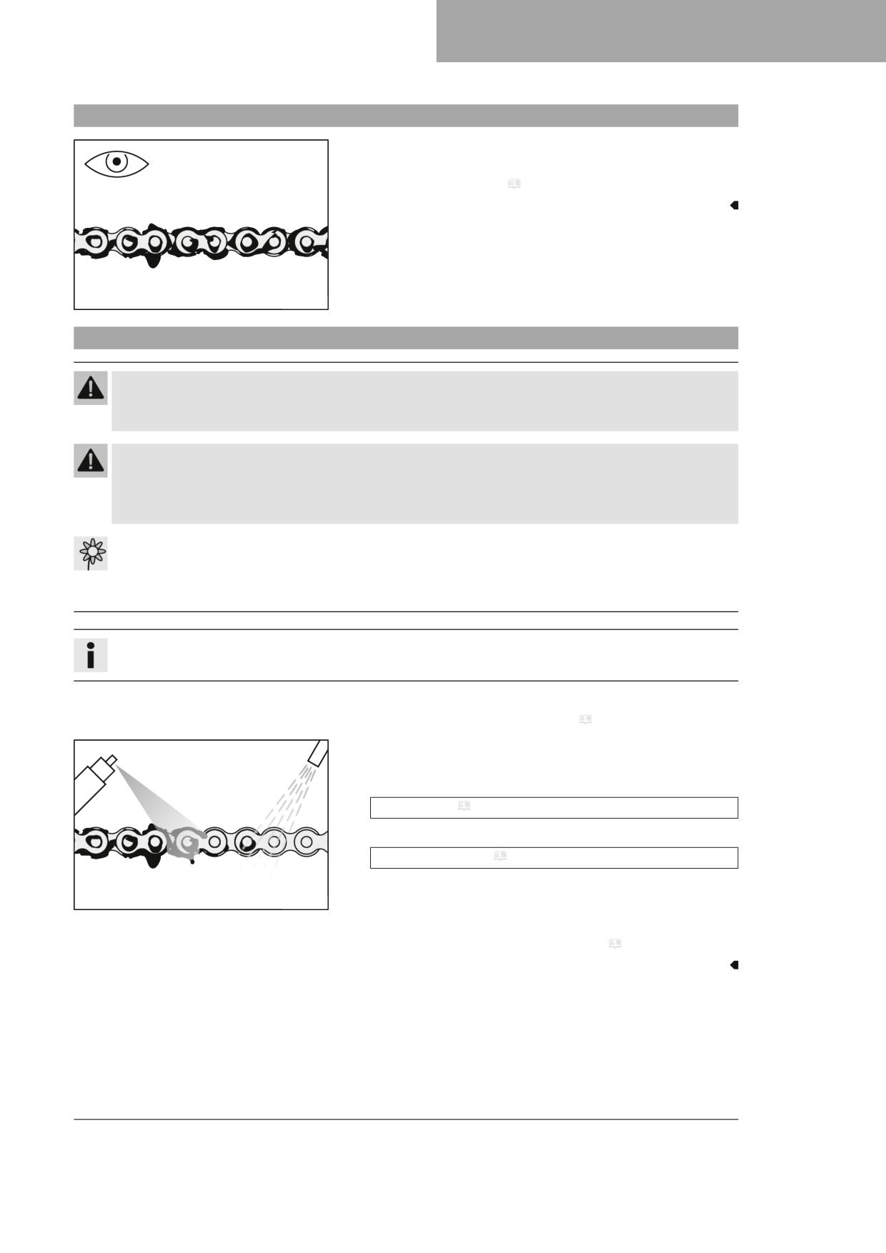
SERVICE WORK ON THE CHASSIS
12
12.34
Checking for chain dirt accumulation
- Check the chain for coarse dirt accumulation.
» If the chain is very dirty:
- Clean the chain. ( p. 73)
400678-01
12.35
Cleaning the chain
Warning
Danger of accidents Lubricants on the tires reduces the road grip.
- Remove lubricants from the tires using a suitable cleaning agent.
Warning
Danger of accidents Oil or grease on the brake discs reduces the braking effect.
- Always keep the brake discs free of oil and grease.
- Clean the brake discs with brake cleaner when necessary.
Note
Environmental hazard Hazardous substances cause environmental damage.
- Dispose of oils, grease, filters, fuel, cleaning agents, brake fluid, etc., correctly and in compliance with the appli-
cable regulations.
Info
The service life of the chain depends largely on its maintenance.
Preparatory work
- Raise the motorcycle with a lift stand. ( p. 50)
Main work
- Rinse off loose dirt with a soft jet of water.
- Remove old grease residue with chain cleaner.
Chain cleaner ( p. 144)
- After drying, apply chain spray.
Off-road chain spray ( p. 144)
400725-01
Finishing work
- Remove the motorcycle from the lift stand. ( p. 50)
73
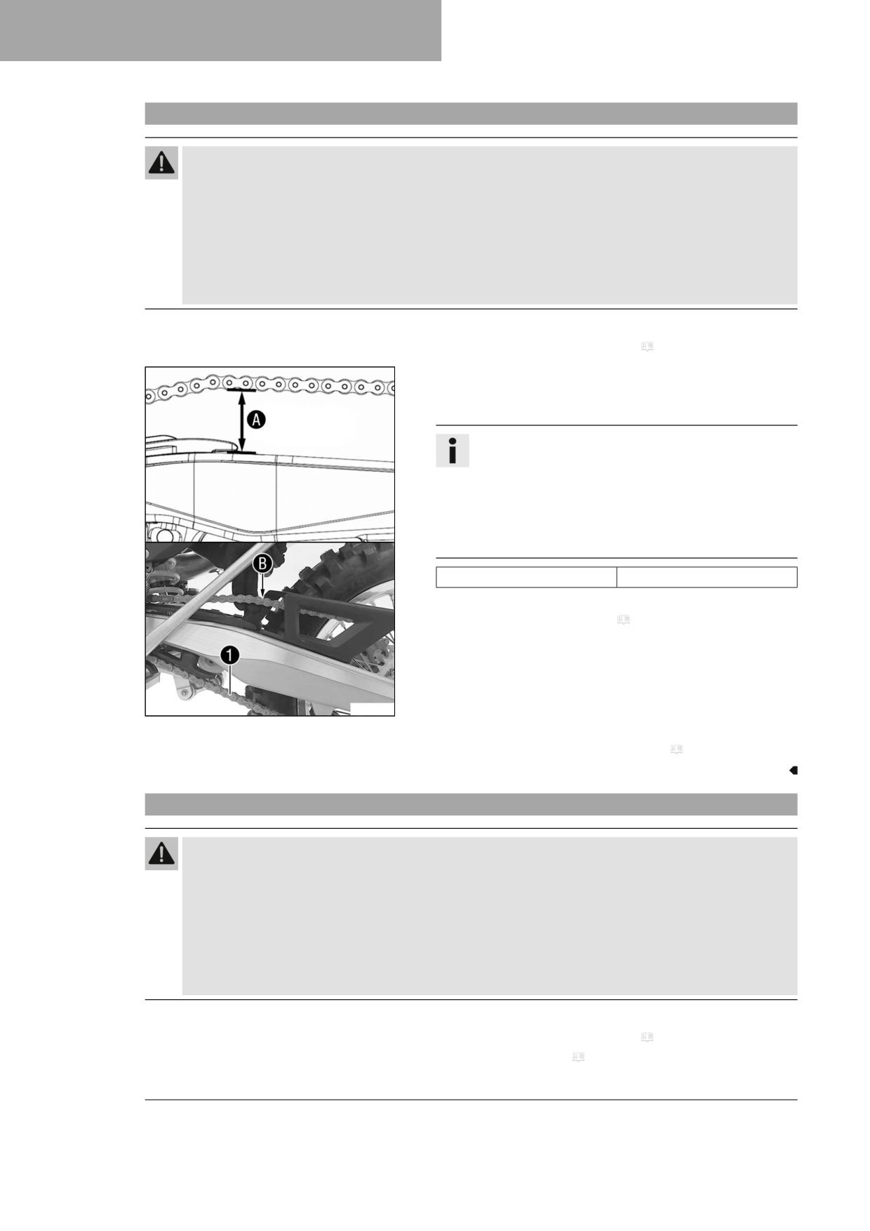
12
SERVICE WORK ON THE CHASSIS
12.36
Checking the chain tension
Warning
Danger of accidents Incorrect chain tension damages components and results in accidents.
If the chain is tensioned too much, the chain, engine sprocket, rear sprocket, transmission and rear wheel bear-
ings wear more quickly. Some components may break if overloaded.
If the chain is too loose, the chain may fall off the engine sprocket or the rear sprocket. As a result, the rear wheel
locks or the engine will be damaged.
- Check the chain tension regularly.
- Set the chain tension in accordance with the specification.
Preparatory work
- Raise the motorcycle with a lift stand. ( p. 50)
Main work
- Pull the chain at the end of the chain sliding piece upward to mea-
sure chain tension A.
Info
Lower chain section 1 must be taut.
When the chain guard is mounted, it must be possible to
pull up the chain at least to the point where it makes contact
with chain guard B.
Chain wear is not always even, so you should repeat this
measurement at different chain positions.
Chain tension
55 … 58 mm (2.17 … 2.28 in)
» If the chain tension does not meet the specification:
- Adjust the chain tension. ( p. 74)
F03213-10
Finishing work
- Remove the motorcycle from the lift stand. ( p. 50)
12.37
Adjusting the chain tension
Warning
Danger of accidents Incorrect chain tension damages components and results in accidents.
If the chain is tensioned too much, the chain, engine sprocket, rear sprocket, transmission and rear wheel bear-
ings wear more quickly. Some components may break if overloaded.
If the chain is too loose, the chain may fall off the engine sprocket or the rear sprocket. As a result, the rear wheel
locks or the engine will be damaged.
- Check the chain tension regularly.
- Set the chain tension in accordance with the specification.
Preparatory work
- Raise the motorcycle with a lift stand. ( p. 50)
- Check the chain tension. ( p. 74)
74
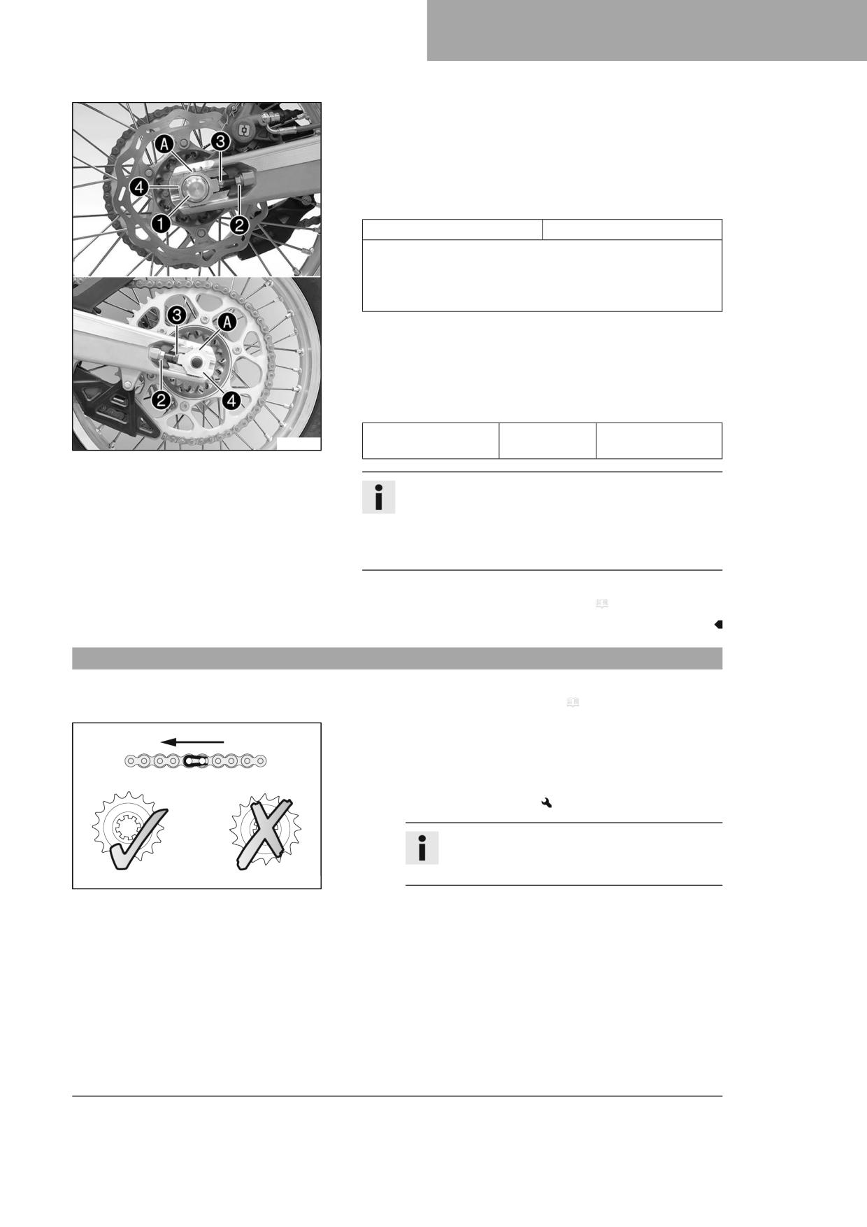
SERVICE WORK ON THE CHASSIS
12
Main work
- Loosen nut 1.
- Loosen nuts 2.
- Adjust the chain tension by turning adjusting screws 3 left and
right.
Guideline
Chain tension
55 … 58 mm (2.17 … 2.28 in)
Turn adjusting screws 3 on the left and right so that the mark-
ings on the left and right chain adjusters are in the same position
relative to reference marks A. The rear wheel is then correctly
aligned.
- Tighten nuts 2.
- Make sure that chain adjusters 4 are fitted correctly on adjusting
screws 3.
- Tighten nut 1.
Guideline
Nut, wheel spindle,
M22x1.5
80 Nm (59 lbf ft)
F03214-10
rear
Info
The wide adjustment range of the chain adjusters (32 mm
(1.26 in)) enables different secondary ratios with the same
chain length.
Chain adjusters 4 can be turned by 180°.
Finishing work
- Remove the motorcycle from the lift stand. ( p. 50)
12.38
Checking the chain, rear sprocket, engine sprocket, and chain guide
Preparatory work
- Raise the motorcycle with a lift stand. ( p. 50)
Main work
- Shift the transmission into neutral.
- Check the chain, rear sprocket, and engine sprocket for wear.
» If the chain, rear sprocket or engine sprocket is worn:
- Change the drivetrain kit.
Info
The engine sprocket, rear sprocket, and chain
should always be replaced together.
400227-01
75
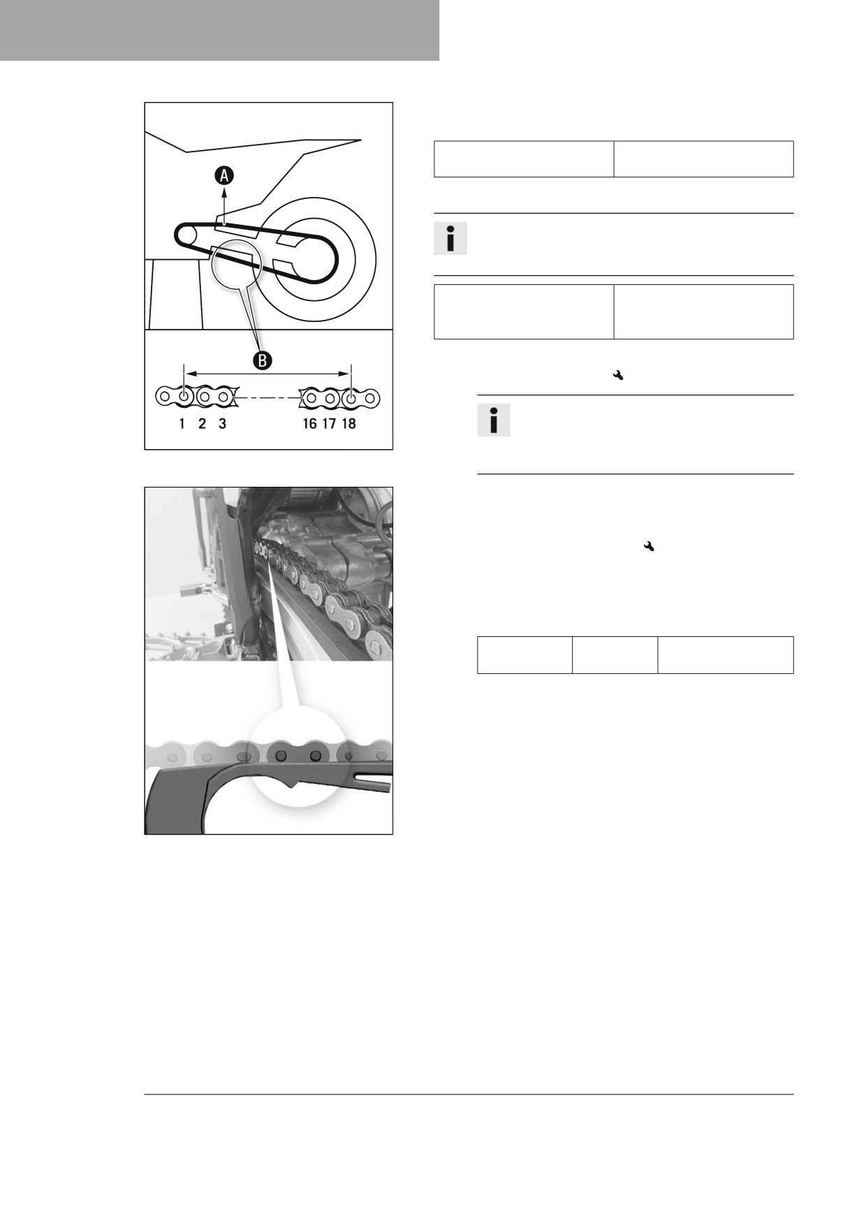
12
SERVICE WORK ON THE CHASSIS
- Pull on the top section of the chain with the specified weight A.
Guideline
Weight of chain wear measure-
10 … 15 kg (22 … 33 lb.)
ment
- Measure distance B of 18 chain rollers in the lower chain section.
Info
Chain wear is not always even, so you should repeat this
measurement at different chain positions.
272 mm (10.71 in)
Maximum distance B from
18 chain rollers at the longest
chain section
» If distance B is greater than the specified measurement:
- Change the drivetrain kit.
Info
When a new chain is mounted, the rear sprocket
400987-10
and engine sprocket should also be changed.
New chains wear out faster on old, worn sprockets.
- Check the chain sliding guard for wear.
» If the lower edge of the chain pins is in line with, or below, the
chain sliding guard:
- Change the chain sliding guard.
- Check that the chain sliding guard is firmly seated.
» If the chain sliding guard is loose:
- Tighten screws on the chain sliding guard.
Guideline
Screw, chain
M6
6 Nm (4.4 lbf ft)
sliding guard
Loctite®243™
W00303-10
76
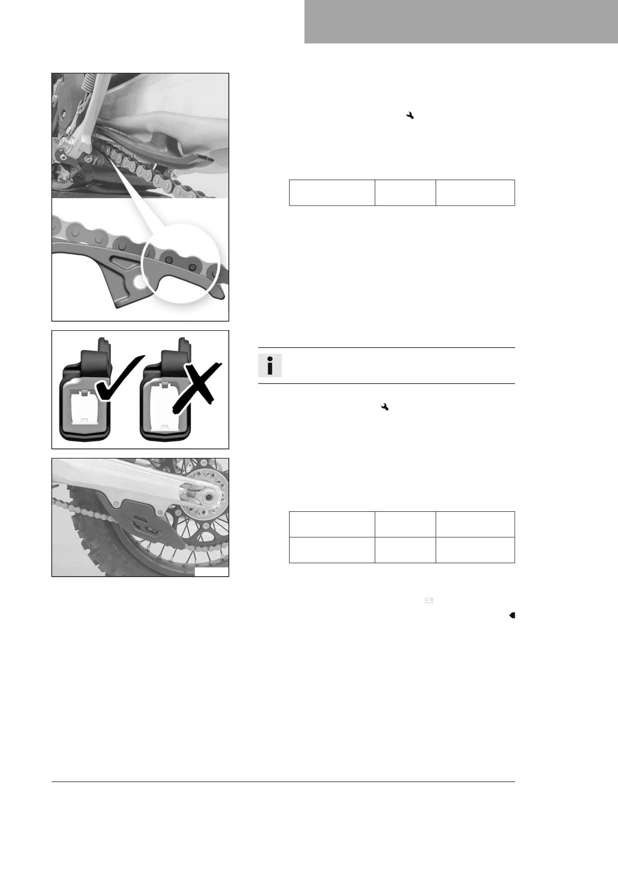
SERVICE WORK ON THE CHASSIS
12
– Check chain sliding piece for wear.
» If the lower edge of the chain pins is in line with or below the
chain sliding piece:
- Change the chain sliding piece.
- Check that the chain sliding piece is firmly seated.
» If the chain sliding piece is loose:
- Tighten the screw of the chain sliding piece.
Guideline
Screw, chain sliding
M8
15 Nm (11.1 lbf ft)
piece
W00304-10
- Check the chain guide for wear.
Info
Wear can be seen on the front of the chain guide.
» If the light part of the chain guide is worn:
- Change the chain guide.
401760-01
- Check that the chain guide is firmly seated.
» If the chain guide is loose:
- Tighten the screws on the chain guide.
Guideline
Remaining screws,
M6
10 Nm (7.4 lbf ft)
chassis
Remaining nuts,
M6
10 Nm (7.4 lbf ft)
chassis
W00305-10
Finishing work
- Remove the motorcycle from the lift stand. ( p. 50)
77
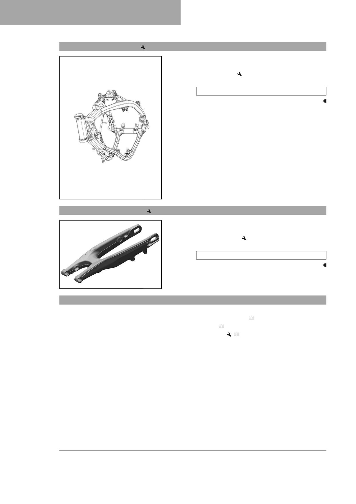
12
SERVICE WORK ON THE CHASSIS
12.39
Checking the frame
- Check the frame for damage, cracking, and deformation.
» If the frame shows signs of damage, cracking, or deformation:
- Change the frame.
Guideline
Repairs on the frame are not permitted.
T04506-01
12.40
Checking the link fork
- Check the link fork for damage, cracks, and deformation.
» If the link fork shows signs of damage, cracks, or deformation:
- Change the link fork.
Guideline
Repairs on the link fork are not permitted.
F03219-01
12.41
Checking the throttle cable routing
Preparatory work
- Remove the air filter box cover. ( p. 63)
- Remove the seat. ( p. 62)
- Remove the fuel tank.
(
p. 70)
78
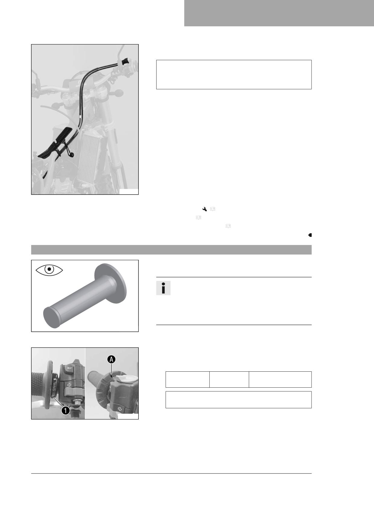
SERVICE WORK ON THE CHASSIS
12
Main work
- Check the throttle cable routing.
Both throttle cables must be routed to the throttle valve body
side by side on the back of the handlebars and above the fuel
tank roller. Both throttle cables must be secured behind the rub-
ber strap of the fuel tank support.
» If the throttle cable routing is not as specified:
- Correct the throttle cable routing.
F03220-01
Finishing work
- Install the fuel tank.
(
p. 71)
– Mount the seat. ( p. 62)
- Install the air filter box cover. ( p. 64)
12.42
Checking the rubber grip
- Check the rubber grips on the handlebar for damage, wear, and
looseness.
Info
The rubber grips are vulcanized onto a sleeve on the left and
onto the handle tube of the throttle grip on the right. The
left sleeve is clamped onto the handlebar.
The rubber grip can only be replaced with the sleeve or the
throttle tube.
401197-01
» If a rubber grip is damaged, worn, or loose:
- Change the rubber grip.
(All EU models)
- Check that screw 1 is firmly seated.
Guideline
Screw, fixed grip
M4
5 Nm (3.7 lbf ft)
Loctite®243™
Diamond A must be positioned visibly as shown in the fig-
ure.
W00325-10
79
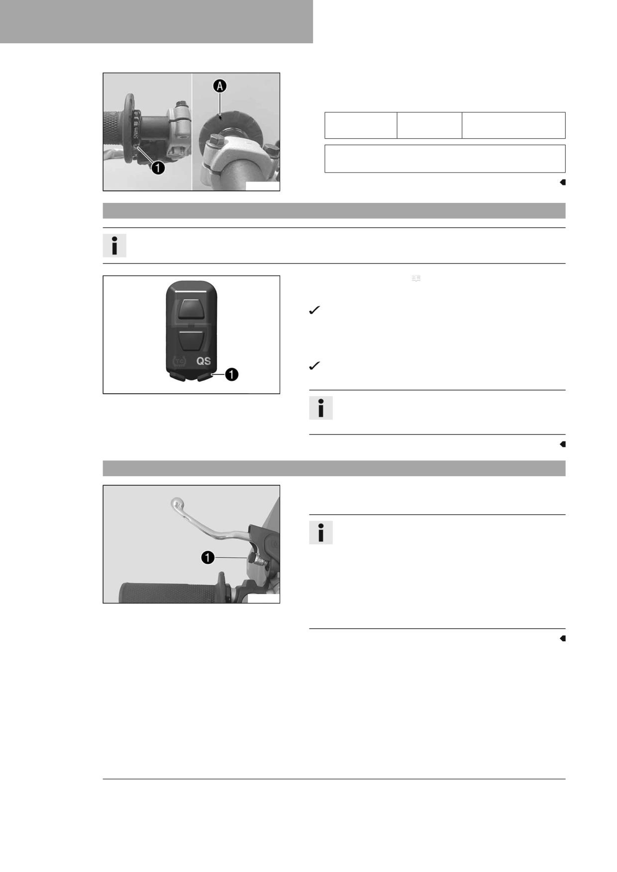
12
SERVICE WORK ON THE CHASSIS
(All US models)
- Check that screw 1 is firmly seated.
Guideline
Screw, fixed grip
M4
5 Nm (3.7 lbf ft)
Loctite®243™
Diamond A must be positioned visibly as shown in the fig-
ure.
W00326-10
12.43
Programming the Quickshifter (optional)
Info
If the shifting performance of the Quickshifter starts to decrease, it must be reprogrammed.
- Carry out start procedure. ( p. 33)
- Press and hold the QS button 1 for at least 10 seconds.
The QS indicator lamp flashes.
- Pull the clutch lever, engage first-gear and hold the shift lever all the
way down.
- Briefly press the QS button 1.
The QS indicator lamp lights up blue, the teaching procedure
was successful.
F03760-12
Info
If the quickshifter cannot be activated, the teaching proce-
dure was unsuccessful and must be repeated.
12.44
Adjusting the basic position of the clutch lever
- Adjust the basic position of the clutch lever to your hand size by
turning adjusting screw 1.
Info
Turn the adjusting screw clockwise to increase the distance
between the clutch lever and the handlebar.
Turn the adjusting screw counterclockwise to decrease the
distance between the clutch lever and the handlebar.
The range of adjustment is limited.
A01332-10
Turn the adjusting screw by hand only, and do not apply any
force.
Do not make any adjustments while riding.
80
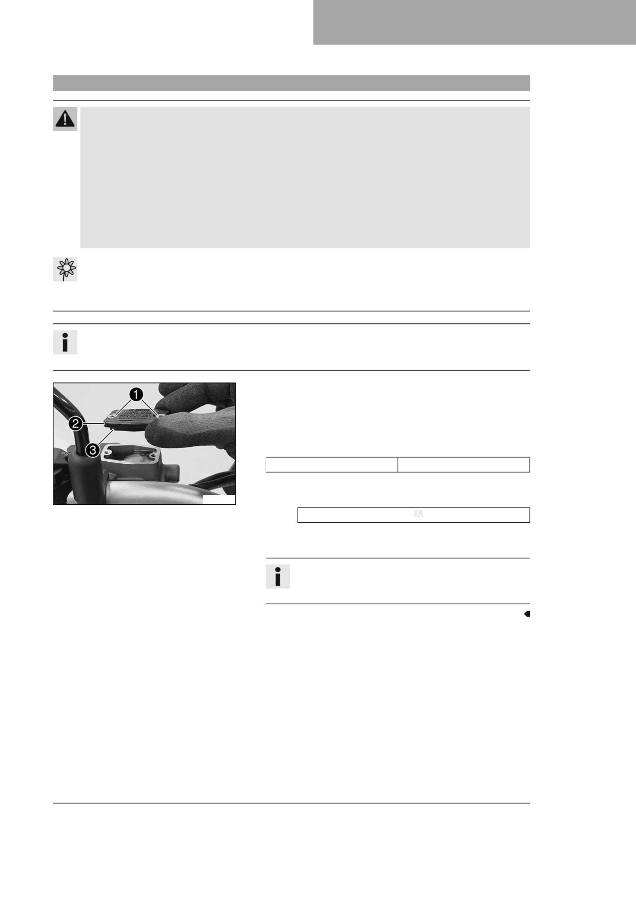
SERVICE WORK ON THE CHASSIS
12
12.45
Checking/correcting the fluid level of hydraulic clutch
Warning
Skin irritation Brake fluid is a harmful substance.
- Keep brake fluid out of the reach of children.
- Wear suitable protective clothing and safety glasses.
- Do not allow brake fluid to come into contact with the skin, the eyes or clothing.
- Consult a doctor immediately if brake fluid has been swallowed.
- Rinse the affected area with plenty of water in the event of contact with the skin.
- Rinse eyes thoroughly with water immediately and consult a doctor if brake fluid comes into contact with the
eyes.
- If brake fluid spills on to your clothing, change the clothing.
Note
Environmental hazard Hazardous substances cause environmental damage.
- Dispose of oils, grease, filters, fuel, cleaning agents, brake fluid, etc., correctly and in compliance with the appli-
cable regulations.
Info
The fluid level rises with increasing wear of the clutch facing discs.
Avoid contact between brake fluid and painted parts. Brake fluid corrodes paint.
- Move the hydraulic clutch fluid reservoir mounted on the handlebar
into a horizontal position.
- Remove screws 1.
- Take off cover 2 with membrane 3.
- Check the fluid level.
Fluid level below container rim
4 mm (0.16 in)
» If the fluid level does not meet specifications:
F03222-10
- Correct the fluid level of the hydraulic clutch.
Brake fluid DOT 4 / DOT 5.1 ( p. 142)
- Position the cover with the membrane. Mount and tighten the
screws.
Info
Use water to immediately clean up any brake fluid that has
overflowed or spilled.
81
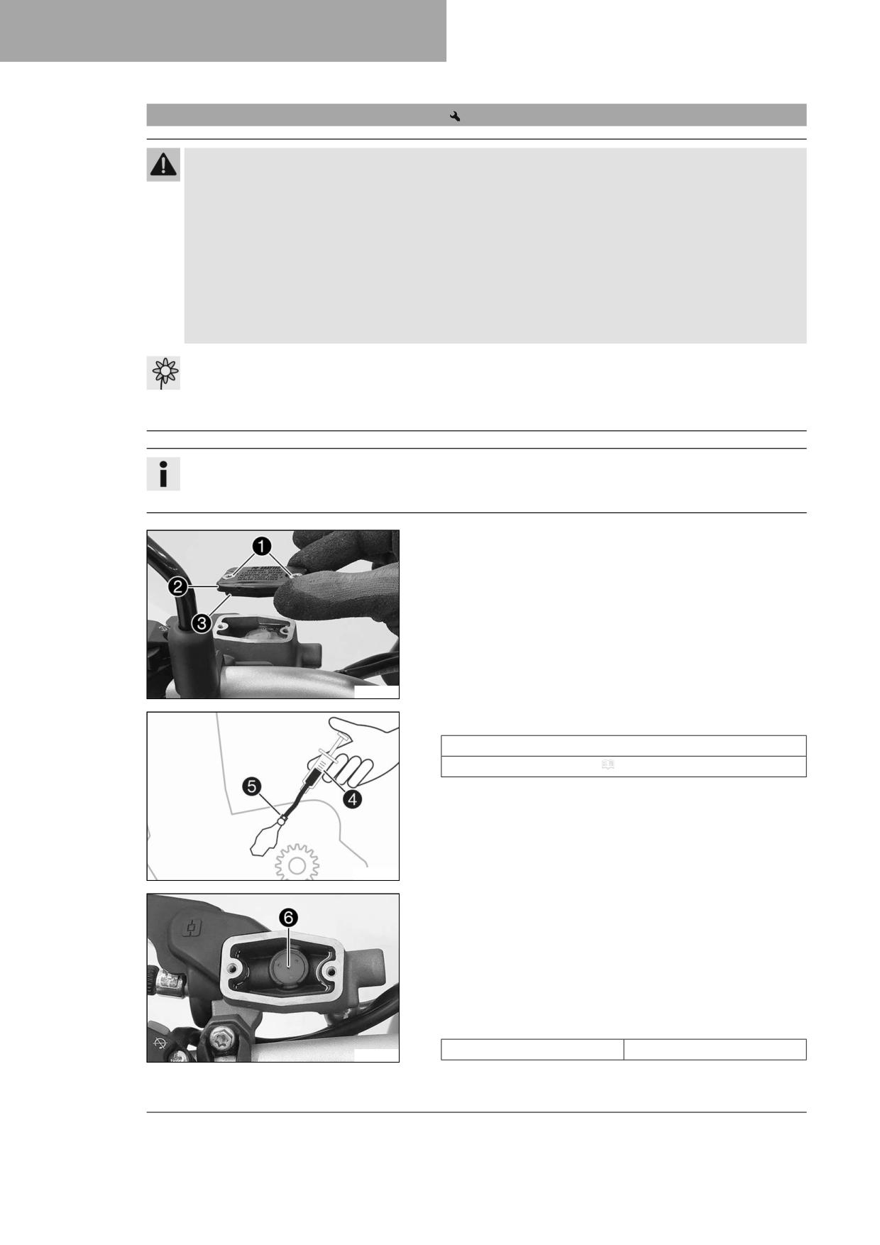
12
SERVICE WORK ON THE CHASSIS
12.46
Changing the hydraulic clutch fluid
Warning
Skin irritation Brake fluid is a harmful substance.
- Keep brake fluid out of the reach of children.
- Wear suitable protective clothing and safety glasses.
- Do not allow brake fluid to come into contact with the skin, the eyes or clothing.
- Consult a doctor immediately if brake fluid has been swallowed.
- Rinse the affected area with plenty of water in the event of contact with the skin.
- Rinse eyes thoroughly with water immediately and consult a doctor if brake fluid comes into contact with the
eyes.
- If brake fluid spills on to your clothing, change the clothing.
Note
Environmental hazard Hazardous substances cause environmental damage.
- Dispose of oils, grease, filters, fuel, cleaning agents, brake fluid, etc., correctly and in compliance with the appli-
cable regulations.
Info
The fluid level rises with increasing wear of the clutch facing discs.
Avoid contact between brake fluid and painted parts. Brake fluid corrodes paint.
- Move the hydraulic clutch fluid reservoir mounted on the handlebar
into a horizontal position.
- Remove screws 1.
- Take off cover 2 with membrane 3.
F03222-10
- Fill bleeding syringe 4 with the appropriate hydraulic fluid.
Syringe (50329050000)
Brake fluid DOT 4 / DOT 5.1 ( p. 142)
- On the clutch slave cylinder, remove the protection cap, remove
bleeder screw 5 and mount bleeding syringe 4.
H04934-10
- Now inject fluid into the system until it escapes from the openings
6 of the master cylinder without bubbles.
- Occasionally extract the fluid from the master cylinder reservoir to
prevent overflowing.
- Remove the bleeding syringe. Mount and tighten the bleeder screw.
Mount the protection cap.
- Correct the fluid level of the hydraulic clutch.
Guideline
Fluid level below container rim
4 mm (0.16 in)
F03223-10
82

SERVICE WORK ON THE CHASSIS
12
– Position the cover with the membrane. Mount and tighten the
screws.
Info
Use water to immediately clean up any brake fluid that has
overflowed or spilled.
83
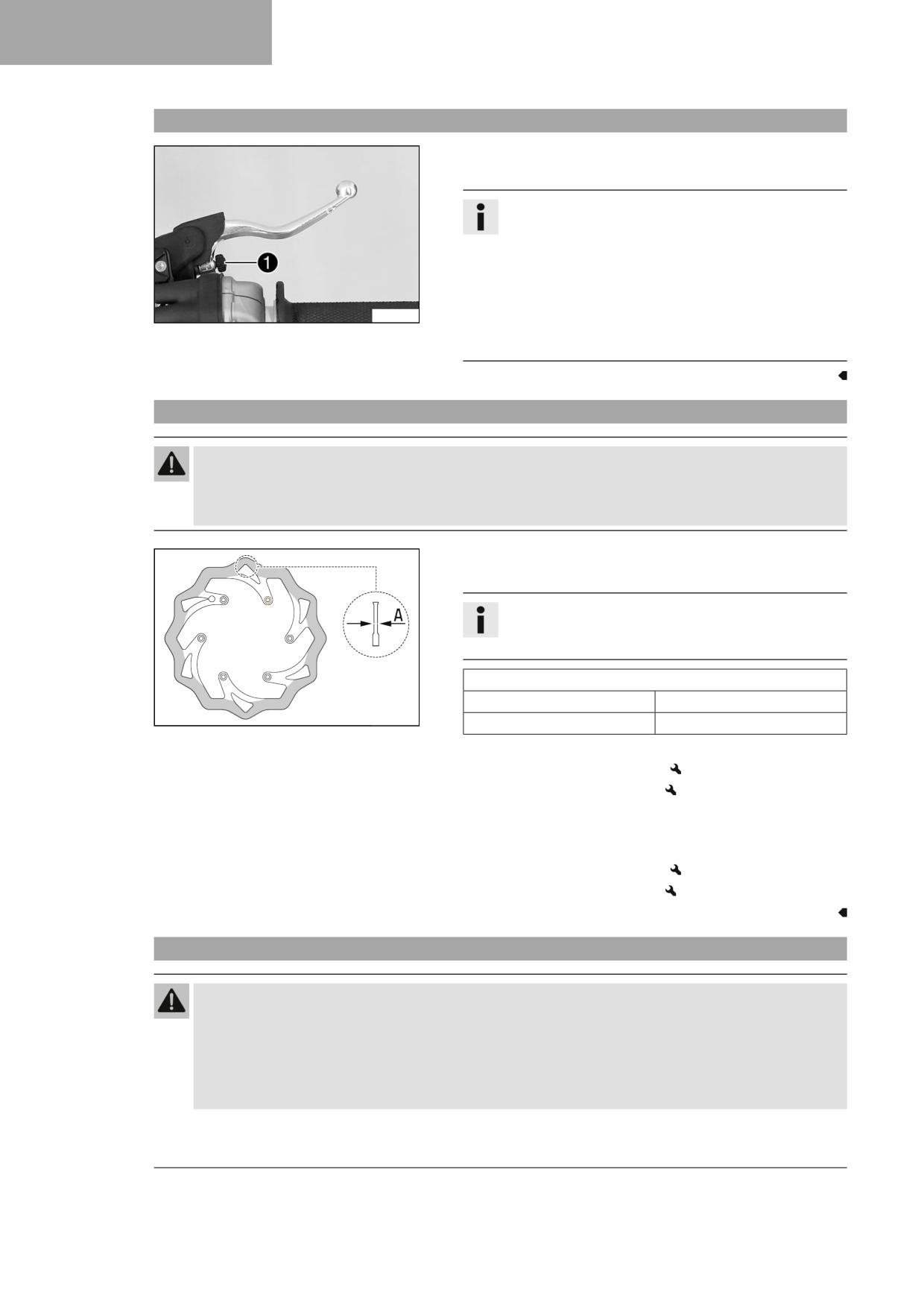
13
BRAKE SYSTEM
13.1
Adjusting the basic position of the hand brake lever
- Adjust basic position of the hand brake lever to your hand size by
turning adjusting screw 1.
Info
Turn the adjusting screw clockwise to increase the distance
between the hand brake lever and the handlebar.
Turn the adjusting screw counterclockwise to decrease the
distance between the hand brake lever and the handlebar.
The range of adjustment is limited.
Turn the adjusting screw by hand only, and do not apply any
F03161-11
force.
Do not make any adjustments while riding.
13.2
Checking the brake discs
Warning
Danger of accidents Worn-out brake discs reduce the braking effect.
- Make sure that worn-out brake discs are replaced immediately. (Your authorized GASGAS Motorcycles work-
shop will be glad to help.)
- Check the front and rear brake disc thickness at multiple points for
the dimension A.
Info
Wear reduces the thickness of the brake disc around the
contact surface of the brake linings.
Brake discs - wear limit
front
2.5 mm (0.098 in)
400257-10
rear
3.5 mm (0.138 in)
» If the brake disc thickness is less than the specified value:
- Change the front brake disc.
- Change the rear brake disc.
- Check the front and rear brake discs for damage, cracking, and
deformation.
» If the brake disc exhibits damage, cracking, or deformation:
- Change the front brake disc.
- Change the rear brake disc.
13.3
Checking the front brake fluid level
Warning
Danger of accidents An insufficient brake fluid level will cause the brake system to fail.
If the brake fluid level drops below the MIN marking, the brake system is leaking or the brake linings are worn
down.
- Check the brake system and do not continue riding until the problem is eliminated. (Your authorized GAS-
GAS Motorcycles workshop will be glad to help.)
84
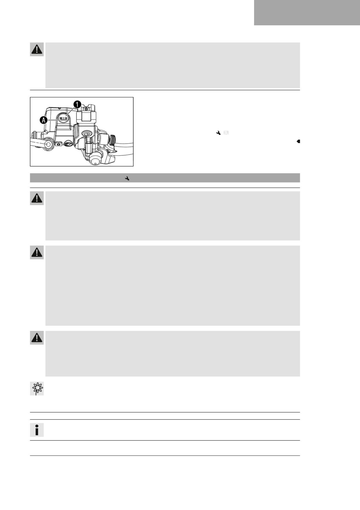
BRAKE SYSTEM
13
Warning
Danger of accidents Brake fluid which is too old or of the wrong type impairs the function of the brake system.
- Make sure that brake fluid for the front and rear brake is changed in accordance with the service schedule.
(Your authorized GASGAS Motorcycles workshop will be glad to help.)
- Make sure that only clean, approved brake fluid from a tightly sealed container is used. (Your authorized GAS-
GAS Motorcycles workshop will be glad to help.)
- Move the brake fluid reservoir mounted on the handlebar to a hori-
zontal position.
- Check the brake fluid level in level viewer 1.
» If the brake fluid level has dropped below the MIN marking A:
- Add front brake fluid.
(
p. 85)
F03262-10
13.4
Adding front brake fluid
Warning
Danger of accidents An insufficient brake fluid level will cause the brake system to fail.
If the brake fluid level drops below the specified marking or the specified value, the brake system is leaking or the
brake linings are worn down.
- Check the brake system and do not continue riding until the problem is eliminated. (Your authorized GAS-
GAS Motorcycles workshop will be glad to help.)
Warning
Skin irritation Brake fluid is a harmful substance.
- Keep brake fluid out of the reach of children.
- Wear suitable protective clothing and safety glasses.
- Do not allow brake fluid to come into contact with the skin, the eyes or clothing.
- Consult a doctor immediately if brake fluid has been swallowed.
- Rinse the affected area with plenty of water in the event of contact with the skin.
- Rinse eyes thoroughly with water immediately and consult a doctor if brake fluid comes into contact with the
eyes.
- If brake fluid spills on to your clothing, change the clothing.
Warning
Danger of accidents Brake fluid which is too old or of the wrong type impairs the function of the brake system.
- Make sure that brake fluid for the front and rear brake is changed in accordance with the service schedule.
(Your authorized GASGAS Motorcycles workshop will be glad to help.)
- Make sure that only clean, approved brake fluid from a tightly sealed container is used. (Your authorized GAS-
GAS Motorcycles workshop will be glad to help.)
Note
Environmental hazard Hazardous substances cause environmental damage.
- Dispose of oils, grease, filters, fuel, cleaning agents, brake fluid, etc., correctly and in compliance with the appli-
cable regulations.
Info
Avoid contact between brake fluid and painted parts. Brake fluid corrodes paint.
85
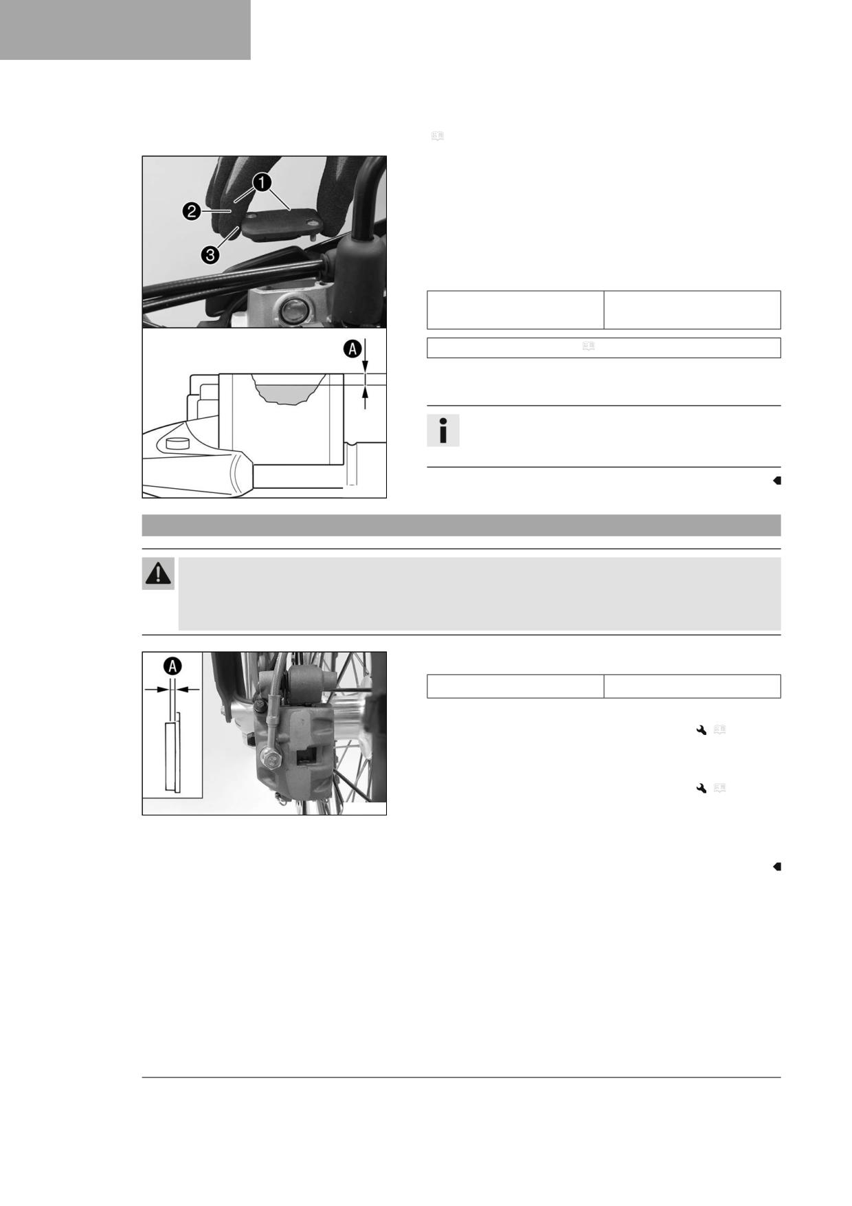
13
BRAKE SYSTEM
Preparatory work
- Check that the brake linings of the front brake are secured.
(
p. 86)
Main work
- Move the brake fluid reservoir mounted on the handlebar to a hori-
zontal position.
- Remove screws 1.
- Take off cover 2 with membrane 3.
- Add brake fluid to level A.
Guideline
5 mm (0.2 in)
Level A (brake fluid level
below reservoir rim)
Brake fluid DOT 4 / DOT 5.1 ( p. 142)
- Position the cover with the membrane. Mount and tighten the
screws.
Info
Use water to immediately clean up any brake fluid that has
overflowed or spilled.
T04631-01
13.5
Checking that the brake linings of the front brake are secured
Warning
Danger of accidents Worn-out brake linings reduce the braking effect.
- Ensure that worn-out brake linings are replaced immediately. (Your authorized GASGAS Motorcycles workshop
will be glad to help.)
- Check the brake linings for lining thickness A.
≥ 1 mm (≥ 0.04 in)
Minimum thickness A
» If it is less than the minimum thickness:
- Change the brake linings of the front brake.
(
p. 87)
– Check the brake linings for damage and cracking.
» If there is damage or cracking:
- Change the brake linings of the front brake.
(
p. 87)
F03227-10
- Check that the brake linings are secured.
» If the brake linings are not secured correctly:
- Secure brake linings, replace with new parts if necessary.
86

BRAKE SYSTEM
13
13.6
Changing the brake linings of the front brake
Warning
Danger of accidents Incorrect servicing will cause the brake system to fail.
- Ensure that service work and repairs are performed professionally. (Your authorized GASGAS Motorcy-
cles workshop will be glad to help.)
Warning
Skin irritation Brake fluid is a harmful substance.
- Keep brake fluid out of the reach of children.
- Wear suitable protective clothing and safety glasses.
- Do not allow brake fluid to come into contact with the skin, the eyes or clothing.
- Consult a doctor immediately if brake fluid has been swallowed.
- Rinse the affected area with plenty of water in the event of contact with the skin.
- Rinse eyes thoroughly with water immediately and consult a doctor if brake fluid comes into contact with the
eyes.
- If brake fluid spills on to your clothing, change the clothing.
Warning
Danger of accidents Brake fluid which is too old or of the wrong type impairs the function of the brake system.
- Make sure that brake fluid for the front and rear brake is changed in accordance with the service schedule.
(Your authorized GASGAS Motorcycles workshop will be glad to help.)
- Make sure that only clean, approved brake fluid from a tightly sealed container is used. (Your authorized GAS-
GAS Motorcycles workshop will be glad to help.)
Warning
Danger of accidents Oil or grease on the brake discs reduces the braking effect.
- Always keep the brake discs free of oil and grease.
- Clean the brake discs with brake cleaner when necessary.
Warning
Danger of accidents Brake linings which have not been approved alter the braking efficiency.
Not all brake linings are tested and approved for GASGAS motorcycles. The structure and friction coefficient of the
brake linings, and thus their brake power, may vary greatly from that of original brake linings.
If brake linings are used that differ from the original equipment, compliance with the original homologation is
not guaranteed. In this case, the vehicle no longer corresponds to its condition at delivery and the manufacturer
warranty shall be void.
- Only use brake linings approved and recommended by GASGAS Motorcycles.
Note
Environmental hazard Hazardous substances cause environmental damage.
- Dispose of oils, grease, filters, fuel, cleaning agents, brake fluid, etc., correctly and in compliance with the appli-
cable regulations.
Info
Avoid contact between brake fluid and painted parts. Brake fluid corrodes paint.
87
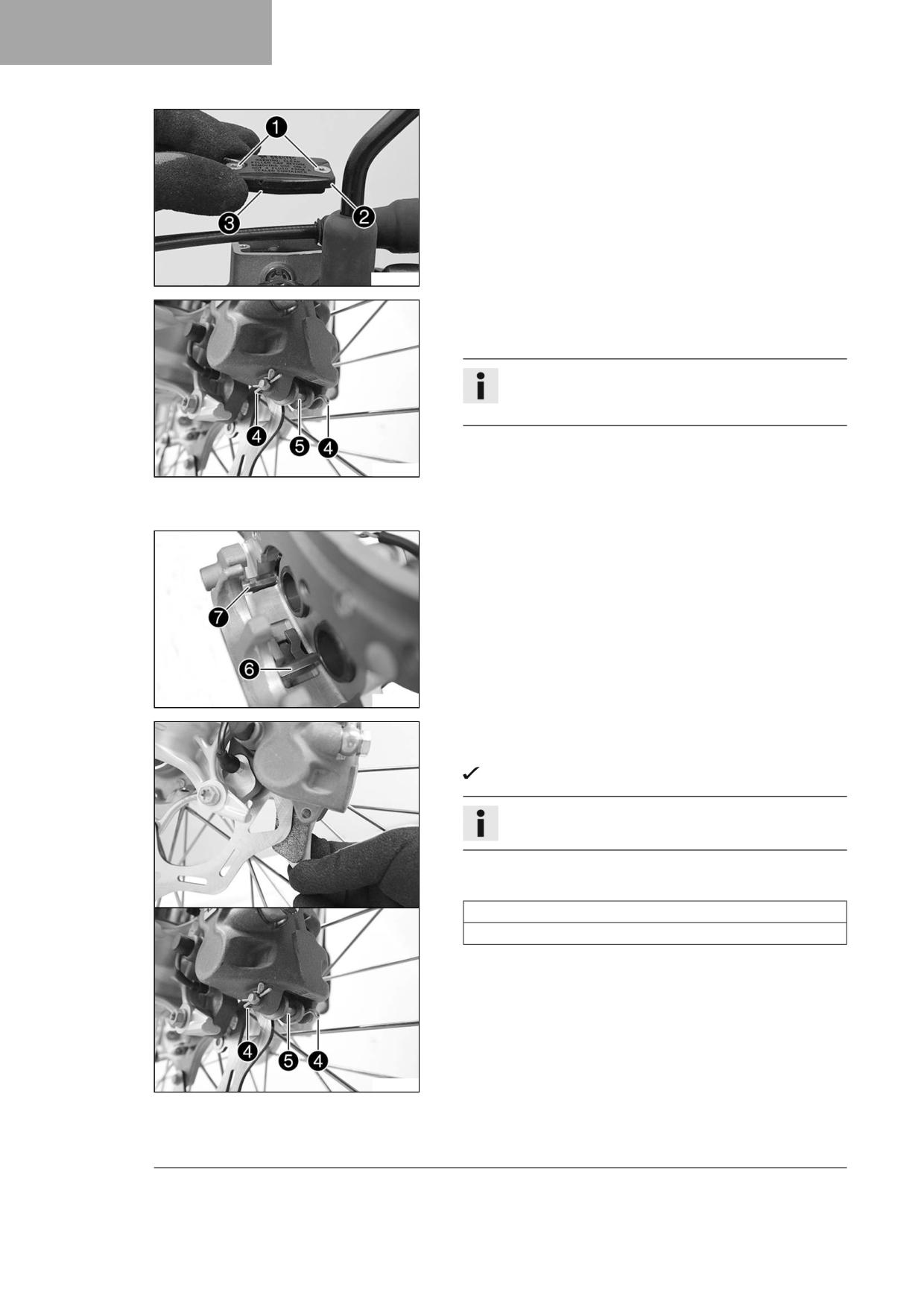
13
BRAKE SYSTEM
- Move the brake fluid reservoir mounted on the handlebar to a hori-
zontal position.
- Remove screws 1.
- Take off cover 2 with membrane 3.
A01333-10
- Manually press the brake caliper toward the brake disc to push back
the brake pistons. Ensure that brake fluid does not flow out of the
brake fluid reservoir; extract some if necessary.
Info
Make sure that you do not press the brake caliper against
the spokes when pushing back the brake pistons.
- Remove cotter pin 4.
S05112-10
- Pull out pin 5.
- Remove the brake linings.
- Clean the brake caliper and the brake caliper bracket.
- Check that spring plate 6 in the brake caliper and brake pad slid-
ing plate 7 in the brake caliper bracket are seated correctly.
S04465-10
- Insert the new brake linings.
- Mount pin 5.
Spring plate 6 engages in the groove on the pin.
Info
Always change the brake linings in pairs.
- Mount cotter pins 4.
Guideline
Mount the outer cotter pins from the front to the rear.
Mount the inner cotter pins from the rear to the front.
- Operate the hand brake lever repeatedly until the brake linings are
in contact with the brake disc and there is a pressure point.
S05113-10
88
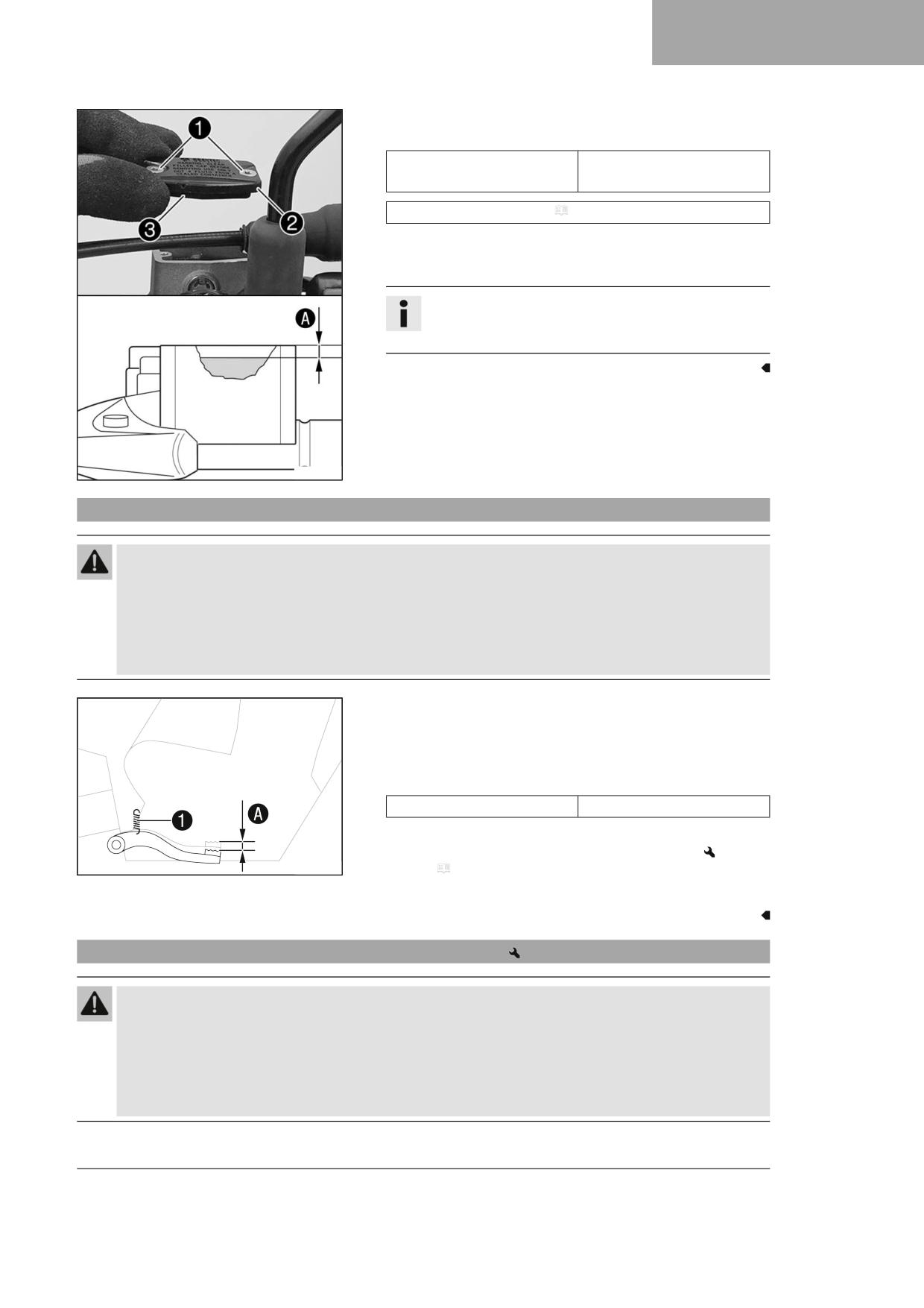
BRAKE SYSTEM
13
– Correct the brake fluid level to level A.
Guideline
5 mm (0.2 in)
Level A (brake fluid level
below reservoir rim)
Brake fluid DOT 4 / DOT 5.1 ( p. 142)
- Position cover 2 with membrane 3.
- Mount and tighten screws 1.
Info
Use water to immediately clean up any brake fluid that has
overflowed or spilled.
A01334-10
13.7
Checking the free travel of foot brake lever
Warning
Danger of accidents The brake system will fail if it overheats or is adjusted incorrectly.
If there is no free travel on the foot brake lever, pressure builds up in the brake system on the rear brake.
- Set the free travel on the foot brake lever in accordance with the specification.
- Ensure that the adjustment steps are performed properly. (Your authorized GASGAS Motorcycles workshop
will be glad to help.)
- Disconnect spring 1.
- Move the foot brake lever back and forth between the end stop
and the contact to the foot brake cylinder piston and check free
travel A.
Guideline
Free travel at foot brake lever
3 … 5 mm (0.12 … 0.2 in)
» If the free travel does not meet specifications:
- Adjust the basic position of the foot brake lever.
402026-10
(
p. 89)
– Reconnect spring 1.
13.8
Adjusting the basic position of the foot brake lever
Warning
Danger of accidents The brake system will fail if it overheats or is adjusted incorrectly.
If there is no free travel on the foot brake lever, pressure builds up in the brake system on the rear brake.
- Set the free travel on the foot brake lever in accordance with the specification.
- Ensure that the adjustment steps are performed properly. (Your authorized GASGAS Motorcycles workshop
will be glad to help.)
89
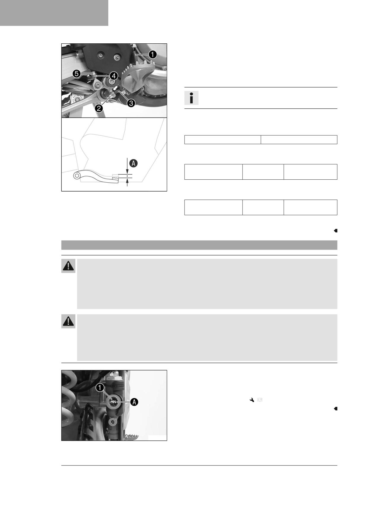
13
BRAKE SYSTEM
- Detach spring 1.
- Loosen nut 4 and, with push rod 5, turn it back until you have
maximum free travel.
- To adjust the basic position of the foot brake lever to individual
requirements, loosen nut 2 and turn screw 3 accordingly.
Info
The range of adjustment is limited.
- Turn push rod 5 accordingly until you have free travel A. If nec-
essary, adjust the basic position of the foot brake lever.
Guideline
Free travel at foot brake lever
3 … 5 mm (0.12 … 0.2 in)
– Hold screw 3 and tighten nut 2.
Guideline
Rear brake lever stop
M8
20 Nm (14.8 lbf ft)
nut
F03229-10
- Hold push rod 5 and tighten nut 4.
Guideline
Remaining nuts, chas-
M6
10 Nm (7.4 lbf ft)
sis
- Attach spring 1.
13.9
Checking the rear brake fluid level
Warning
Danger of accidents An insufficient brake fluid level will cause the brake system to fail.
If the brake fluid level drops below the MIN marking, the brake system is leaking or the brake linings are worn
down.
- Check the brake system and do not continue riding until the problem is eliminated. (Your authorized GAS-
GAS Motorcycles workshop will be glad to help.)
Warning
Danger of accidents Brake fluid which is too old or of the wrong type impairs the function of the brake system.
- Make sure that brake fluid for the front and rear brake is changed in accordance with the service schedule.
(Your authorized GASGAS Motorcycles workshop will be glad to help.)
- Make sure that only clean, approved brake fluid from a tightly sealed container is used. (Your authorized GAS-
GAS Motorcycles workshop will be glad to help.)
- Position the vehicle upright.
- Check the brake fluid level in level viewer 1.
» If the brake fluid level has dropped below the MIN marking A:
- Add rear brake fluid.
(
p. 91)
F03230-10
90
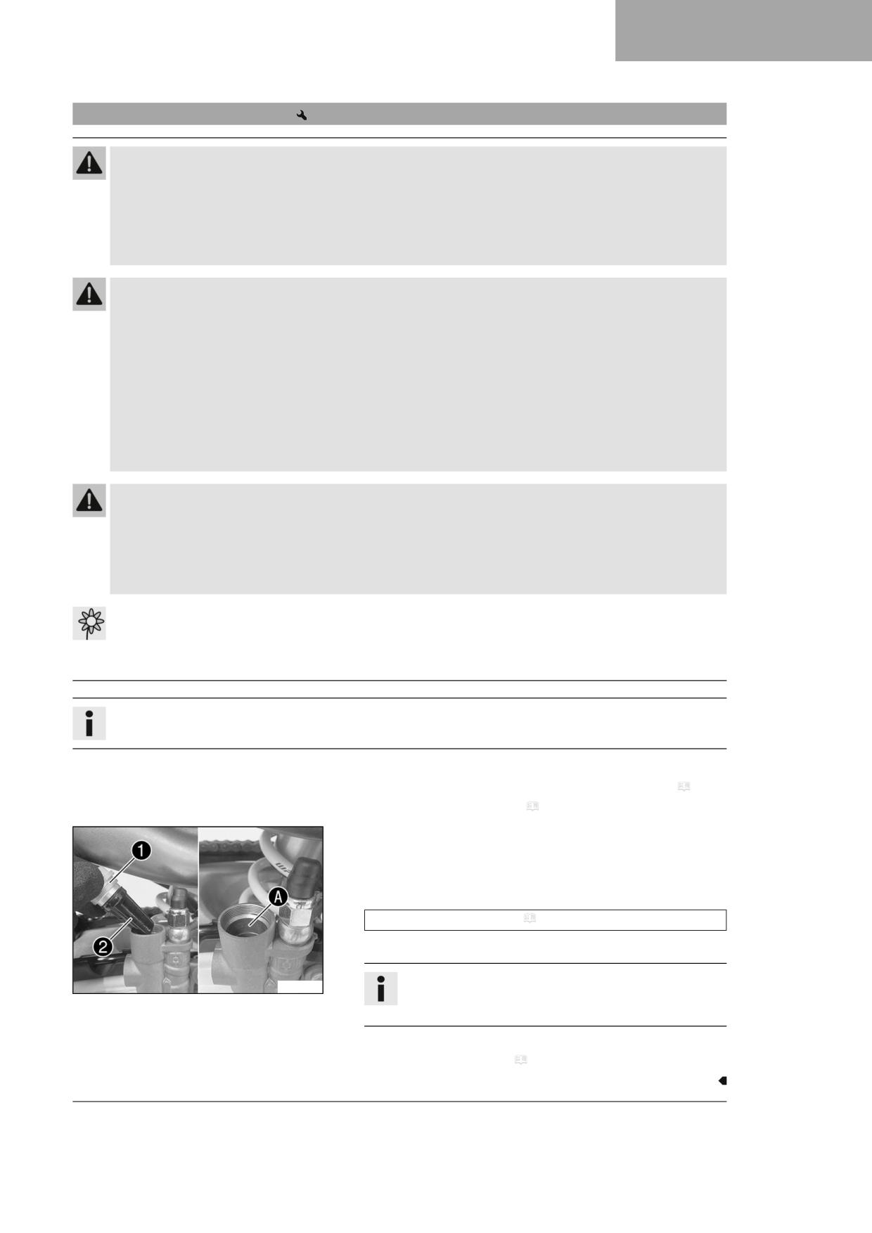
BRAKE SYSTEM
13
13.10
Adding rear brake fluid
Warning
Danger of accidents An insufficient brake fluid level will cause the brake system to fail.
If the brake fluid level drops below the specified marking or the specified value, the brake system is leaking or the
brake linings are worn down.
- Check the brake system and do not continue riding until the problem is eliminated. (Your authorized GAS-
GAS Motorcycles workshop will be glad to help.)
Warning
Skin irritation Brake fluid is a harmful substance.
- Keep brake fluid out of the reach of children.
- Wear suitable protective clothing and safety glasses.
- Do not allow brake fluid to come into contact with the skin, the eyes or clothing.
- Consult a doctor immediately if brake fluid has been swallowed.
- Rinse the affected area with plenty of water in the event of contact with the skin.
- Rinse eyes thoroughly with water immediately and consult a doctor if brake fluid comes into contact with the
eyes.
- If brake fluid spills on to your clothing, change the clothing.
Warning
Danger of accidents Brake fluid which is too old or of the wrong type impairs the function of the brake system.
- Make sure that brake fluid for the front and rear brake is changed in accordance with the service schedule.
(Your authorized GASGAS Motorcycles workshop will be glad to help.)
- Make sure that only clean, approved brake fluid from a tightly sealed container is used. (Your authorized GAS-
GAS Motorcycles workshop will be glad to help.)
Note
Environmental hazard Hazardous substances cause environmental damage.
- Dispose of oils, grease, filters, fuel, cleaning agents, brake fluid, etc., correctly and in compliance with the appli-
cable regulations.
Info
Avoid contact between brake fluid and painted parts. Brake fluid corrodes paint.
Preparatory work
- Check that the brake linings of the rear brake are secured. ( p. 92)
- Remove the frame protector. ( p. 53)
Main work
- Stand the vehicle upright.
- Remove screw cap 1 with membrane 2 and the O-ring.
- Add brake fluid up to the marking A.
Brake fluid DOT 4 / DOT 5.1 ( p. 142)
- Mount and tighten the screw cap with the membrane and O-ring.
Info
A01384-10
Use water to immediately clean up any brake fluid that has
overflowed or spilled.
Finishing work
- Install the frame protector. ( p. 54)
91
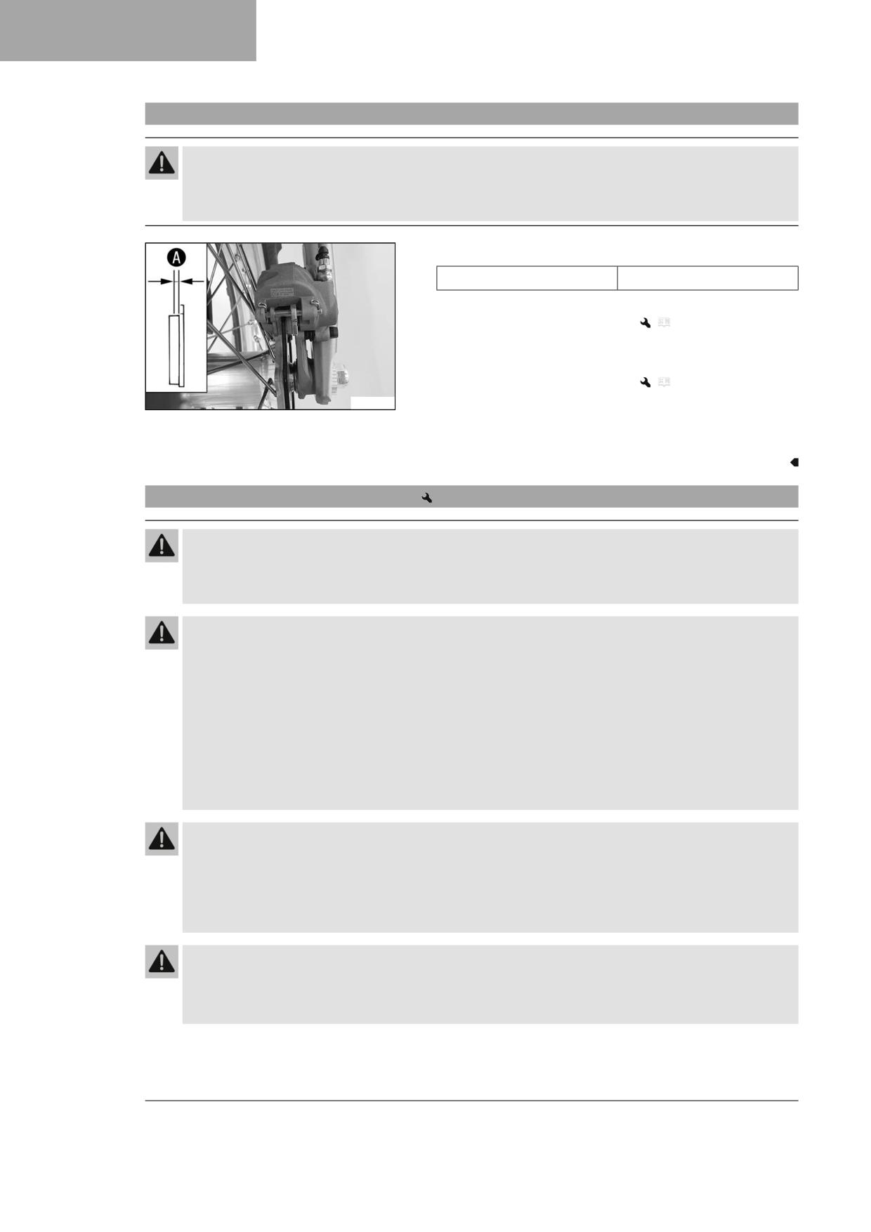
13
BRAKE SYSTEM
13.11
Checking that the brake linings of the rear brake are secured
Warning
Danger of accidents Worn-out brake linings reduce the braking effect.
- Ensure that worn-out brake linings are replaced immediately. (Your authorized GASGAS Motorcycles workshop
will be glad to help.)
- Check the brake linings for lining thickness A.
≥ 1 mm (≥ 0.04 in)
Minimum thickness A
» If it is less than the minimum thickness:
- Change the rear brake linings.
(
p. 92)
– Check the brake linings for damage and cracking.
» If there is damage or cracking:
- Change the rear brake linings.
(
p. 92)
F03232-10
- Check that the brake linings are secured.
» If the brake linings are not secured correctly:
- Secure brake linings, replace with new parts if necessary.
13.12
Changing the rear brake linings
Warning
Danger of accidents Incorrect servicing will cause the brake system to fail.
- Ensure that service work and repairs are performed professionally. (Your authorized GASGAS Motorcy-
cles workshop will be glad to help.)
Warning
Skin irritation Brake fluid is a harmful substance.
- Keep brake fluid out of the reach of children.
- Wear suitable protective clothing and safety glasses.
- Do not allow brake fluid to come into contact with the skin, the eyes or clothing.
- Consult a doctor immediately if brake fluid has been swallowed.
- Rinse the affected area with plenty of water in the event of contact with the skin.
- Rinse eyes thoroughly with water immediately and consult a doctor if brake fluid comes into contact with the
eyes.
- If brake fluid spills on to your clothing, change the clothing.
Warning
Danger of accidents Brake fluid which is too old or of the wrong type impairs the function of the brake system.
- Make sure that brake fluid for the front and rear brake is changed in accordance with the service schedule.
(Your authorized GASGAS Motorcycles workshop will be glad to help.)
- Make sure that only clean, approved brake fluid from a tightly sealed container is used. (Your authorized GAS-
GAS Motorcycles workshop will be glad to help.)
Warning
Danger of accidents Oil or grease on the brake discs reduces the braking effect.
- Always keep the brake discs free of oil and grease.
- Clean the brake discs with brake cleaner when necessary.
92
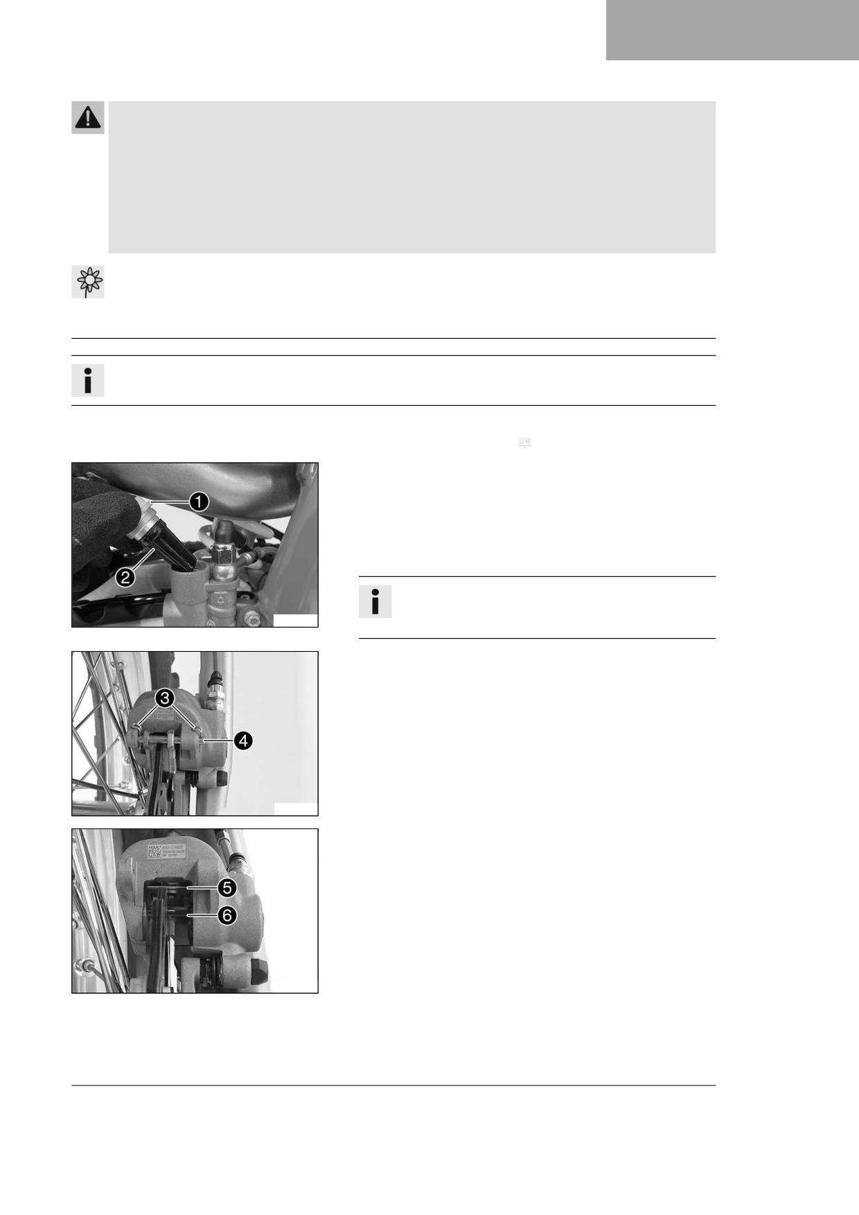
BRAKE SYSTEM
13
Warning
Danger of accidents Brake linings which have not been approved alter the braking efficiency.
Not all brake linings are tested and approved for GASGAS motorcycles. The structure and friction coefficient of the
brake linings, and thus their brake power, may vary greatly from that of original brake linings.
If brake linings are used that differ from the original equipment, compliance with the original homologation is
not guaranteed. In this case, the vehicle no longer corresponds to its condition at delivery and the manufacturer
warranty shall be void.
- Only use brake linings approved and recommended by GASGAS Motorcycles.
Note
Environmental hazard Hazardous substances cause environmental damage.
- Dispose of oils, grease, filters, fuel, cleaning agents, brake fluid, etc., correctly and in compliance with the appli-
cable regulations.
Info
Avoid contact between brake fluid and painted parts. Brake fluid corrodes paint.
Preparatory work
- Remove the frame protector. ( p. 53)
Main work
- Stand the vehicle upright.
- Remove screw cap 1 with membrane 2 and the O-ring.
- Press the brake piston back into the basic position and ensure that
brake fluid does not flow out of the brake fluid reservoir; extract
some if necessary.
Info
Make sure that you do not press the brake caliper against
A01382-10
the spokes when pushing back the brake piston.
- Remove cotter pin 3, pull out pin 4, and remove the brake lin-
ings.
- Clean the brake caliper and the brake caliper bracket.
F03234-10
- Check that spring plate 5 in the brake caliper and brake pad slid-
ing plate 6 in the brake caliper bracket are seated correctly.
F03235-10
93
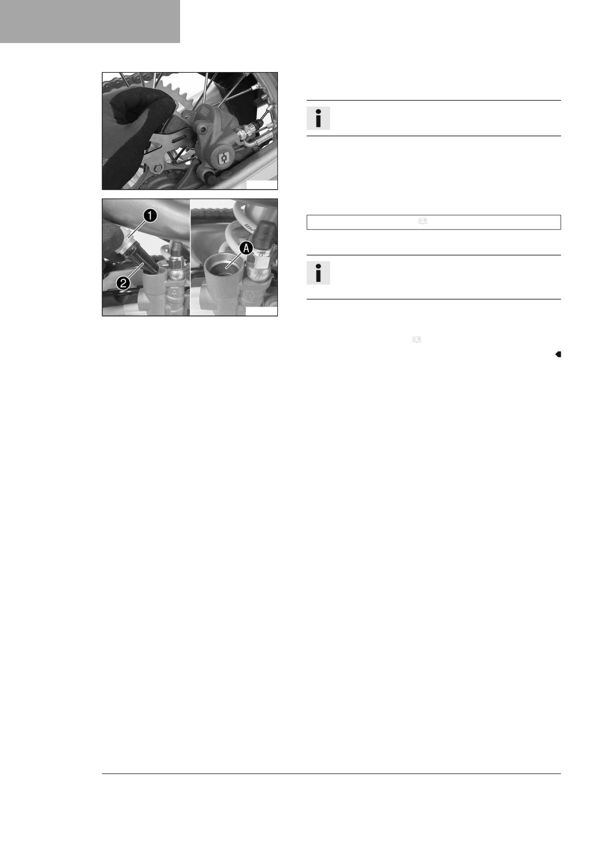
13
BRAKE SYSTEM
- Insert the new brake linings, insert the pin, and mount the cotter
pins.
Info
Always change the brake linings in pairs.
- Operate the foot brake lever repeatedly until the brake linings are in
contact with the brake disc and there is a pressure point.
F03236-01
- Correct brake fluid level to marking A.
Brake fluid DOT 4 / DOT 5.1 ( p. 142)
- Mount screw cap 1 with membrane 2 and O-ring.
Info
Use water to immediately clean up any brake fluid that has
overflowed or spilled.
A01384-10
Finishing work
- Install the frame protector. ( p. 54)
94
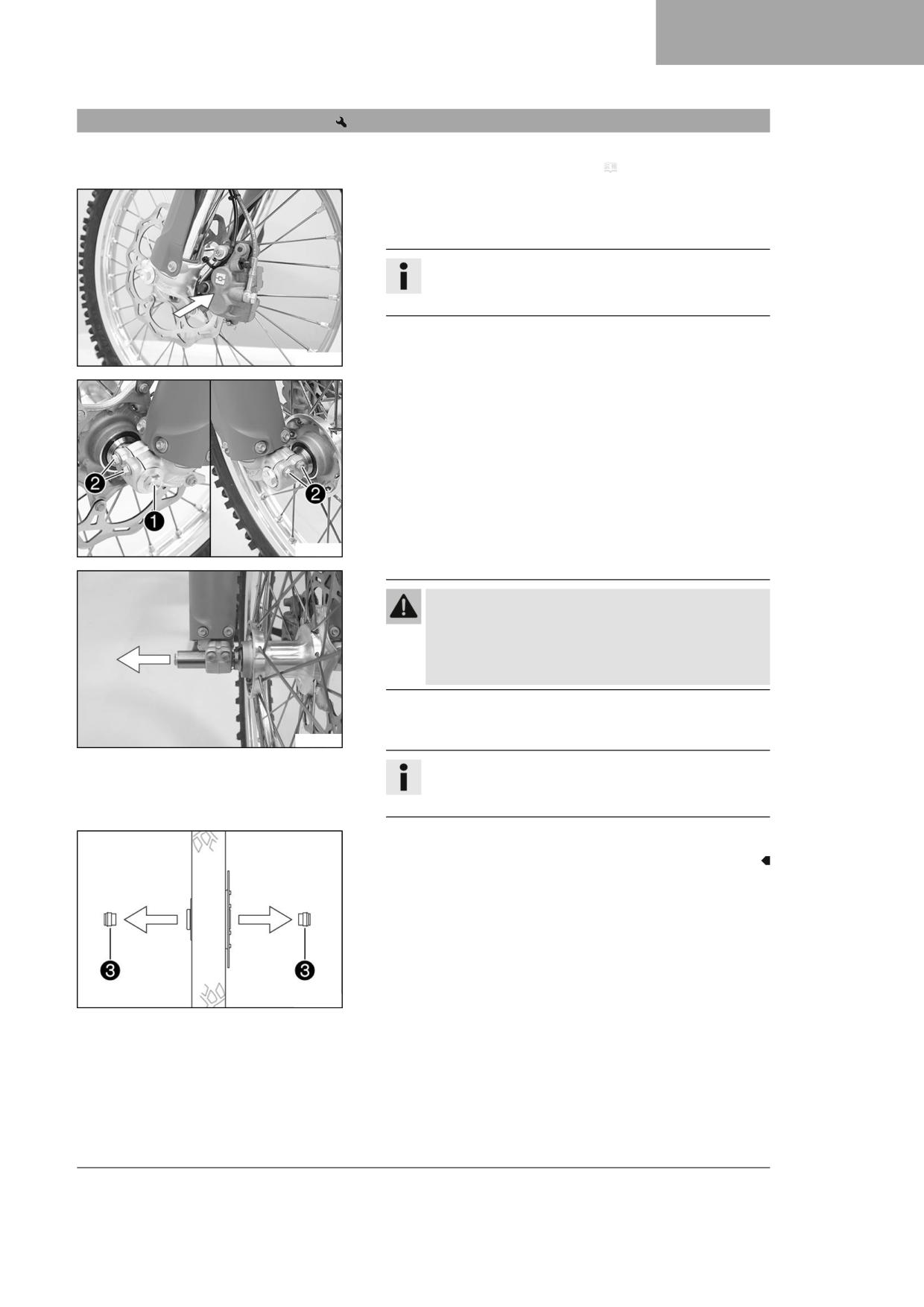
WHEELS, TIRES
14
14.1
Removing the front wheel
Preparatory work
- Raise the motorcycle with a lift stand. ( p. 50)
Main work
- Manually press the brake caliper toward the brake disc to push back
the brake pistons.
Info
Make sure that you do not press the brake caliper against
the spokes when pushing back the brake pistons.
S04473-01
- Loosen screw 1 by several rotations.
- Loosen screws 2.
- Press on screw 1 to push the wheel spindle out of the axle clamp.
- Remove screw 1.
S04474-10
Warning
Danger of accidents Damaged brake discs reduce the
braking effect.
- Always lay the wheel down in such a way that the brake
disc is not damaged.
- Hold front wheel and remove wheel spindle. Take front wheel out of
the fork.
S04475-01
Info
Do not actuate the hand brake lever when the front wheel is
removed.
- Remove spacers 3.
H00934-10
95
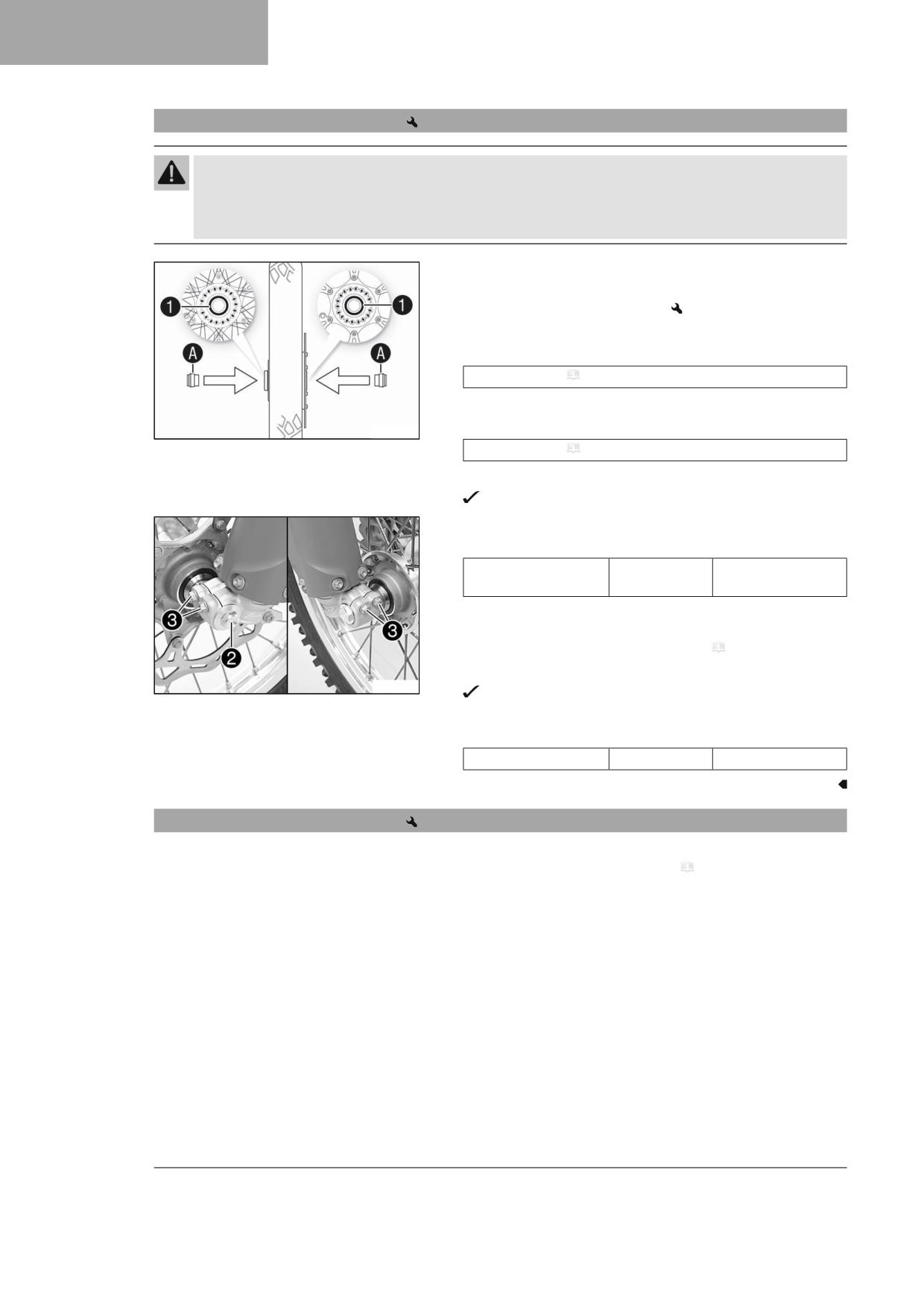
14
WHEELS, TIRES
14.2
Installing the front wheel
Warning
Danger of accidents Oil or grease on the brake discs reduces the braking effect.
- Always keep the brake discs free of oil and grease.
- Clean the brake discs with brake cleaner when necessary.
- Check the wheel bearing for damage and wear.
» If the wheel bearing is damaged or worn:
- Change front wheel bearing.
- Clean and grease shaft seal rings 1 and contact surfaces A of the
spacers.
Long-life grease ( p. 144)
- Insert the spacers.
- Clean and grease the wheel spindle.
H00935-10
Long-life grease ( p. 144)
- Position the front wheel and insert the wheel spindle.
The brake linings are correctly positioned.
- Mount and tighten screw 2.
Guideline
Screw, front wheel
M20x1.5
35 Nm (25.8 lbf ft)
spindle
- Operate the hand brake lever several times until the brake linings
are seated correctly against the brake disc.
- Remove the motorcycle from the lift stand. ( p. 50)
- Operate the front brake and compress the fork a few times firmly.
S04474-11
The fork legs straighten.
- Tighten screws 3.
Guideline
Screw, fork stub
M8
15 Nm (11.1 lbf ft)
14.3
Removing the rear wheel
Preparatory work
- Raise the motorcycle with a lift stand. ( p. 50)
96
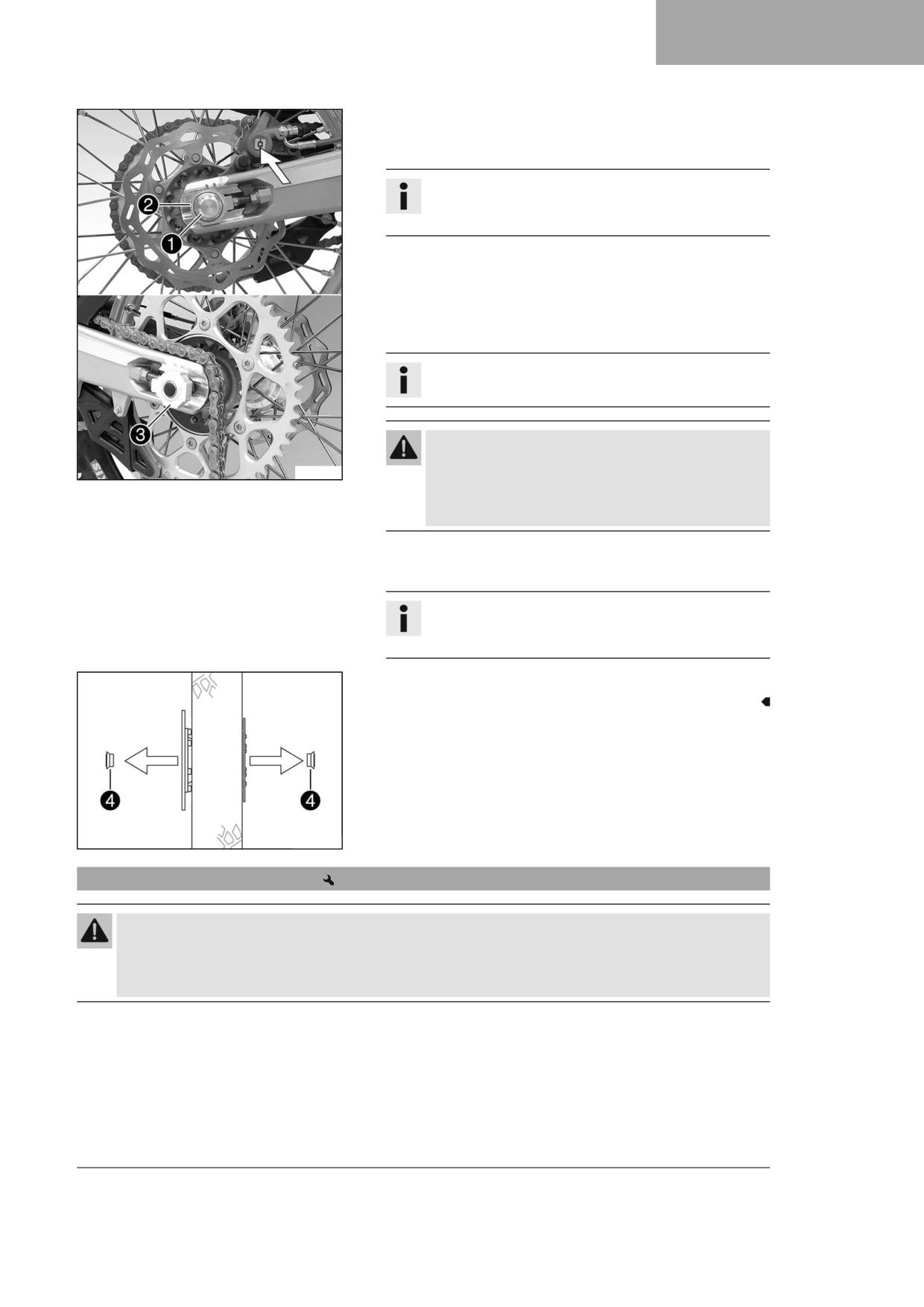
WHEELS, TIRES
14
Main work
- Manually press the brake caliper toward the brake disc to push back
the brake piston.
Info
Make sure that you do not press the brake caliper against
the spokes when pushing back the brake piston.
- Remove nut 1.
- Take off chain adjuster 2. Pull out wheel spindle 3 far enough to
allow the rear wheel to be pushed forward.
- Push the rear wheel forward as far as possible. Remove the chain
from the rear sprocket.
Info
Cover the components to protect them against damage.
Warning
Danger of accidents Damaged brake discs reduce the
F03238-10
braking effect.
- Always lay the wheel down in such a way that the brake
disc is not damaged.
- Hold the rear wheel and remove the wheel spindle. Take the rear
wheel out of the link fork.
Info
Do not operate the foot brake lever when the rear wheel is
removed.
- Remove spacers 4.
H03002-10
14.4
Installing the rear wheel
Warning
Danger of accidents Oil or grease on the brake discs reduces the braking effect.
- Always keep the brake discs free of oil and grease.
- Clean the brake discs with brake cleaner when necessary.
97
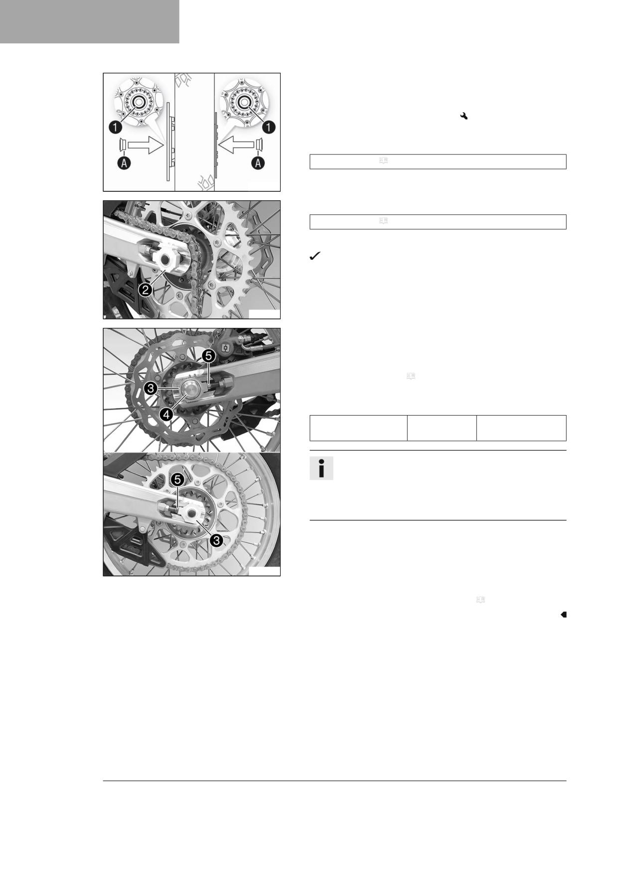
14
WHEELS, TIRES
Main work
- Check the wheel bearing for damage and wear.
» If the wheel bearing is damaged or worn:
- Change the rear wheel bearing.
- Clean and grease shaft seal rings 1 and contact surfaces A of the
spacers.
Long-life grease ( p. 144)
- Insert the spacers.
H03001-10
- Clean and grease the wheel spindle.
Long-life grease ( p. 144)
- Position rear wheel and insert wheel spindle 2.
The brake linings are correctly positioned.
- Mount the chain.
F03237-10
- Position chain adjuster 3. Mount nut 4, but do not tighten it yet.
- Make sure that chain adjusters 3 are fitted correctly on adjusting
screws 5.
- Check the chain tension. ( p. 74)
- Tighten nut 4.
Guideline
Nut, wheel spindle,
M22x1.5
80 Nm (59 lbf ft)
rear
Info
The wide adjustment range of the chain adjusters (32 mm
(1.26 in)) enables different secondary ratios with the same
chain length.
Chain adjusters 3 can be turned by 180°.
- Operate the foot brake lever repeatedly until the brake linings are in
contact with the brake disc and there is a pressure point.
F03214-11
Finishing work
- Remove the motorcycle from the lift stand. ( p. 50)
98
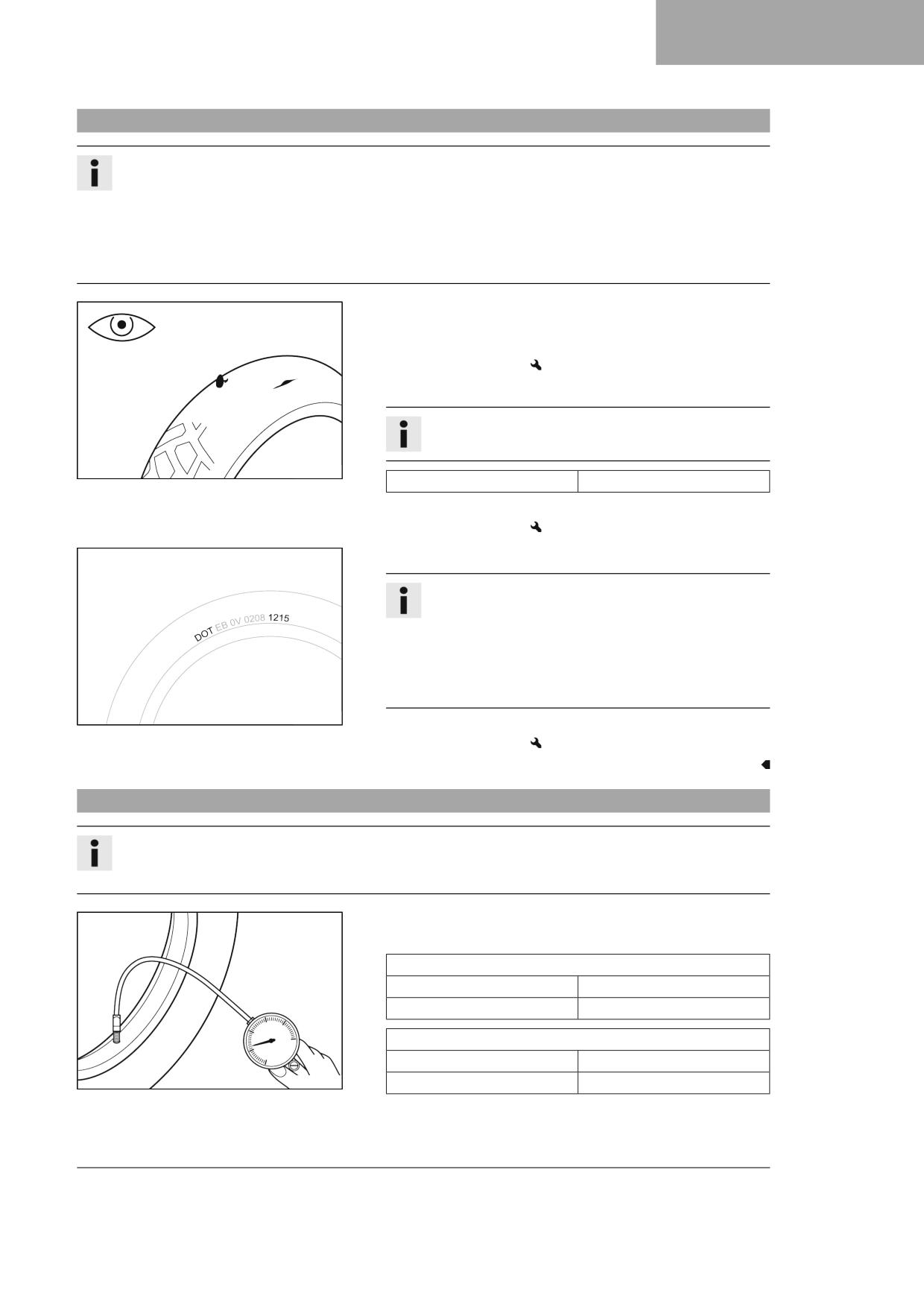
WHEELS, TIRES
14
14.5
Checking the tire condition
Info
Only mount tires approved and/or recommended by GASGAS Motorcycles.
Other tires could have a negative effect on handling characteristics.
The type, condition, and pressure of the tires all have a major impact on the handling characteristic of the motorcy-
cle.
The tires mounted on the front and rear wheels must have a similar profile.
Worn tires have a negative effect on handling characteristics, especially on wet surfaces.
- Check the front and rear tires for cuts, embedded objects, and other
damage.
» If the tires have cuts, run-in objects, or other damage:
- Change the tires.
- Check tread depth.
Info
Adhere to the legally required minimum tread depth.
400602-10
Minimum tread depth
≥ 2 mm (≥ 0.08 in)
» If the tread depth is less than the minimum tread depth:
- Change the tires.
- Check the tire age.
Info
The tire date of manufacture is usually contained in the tire
label and is indicated by the last four digits of the DOT num-
ber. The first two digits indicate the week of manufacture
and the last two digits the year of manufacture.
GASGAS Motorcycles recommends that the tires be changed
after five years at the latest, regardless of the actual wear.
H01144-01
» If the tires are more than five years old:
- Change the tires.
14.6
Checking tire pressure
Info
Low tire pressure leads to abnormal wear and overheating of the tire.
Correct tire pressure ensures optimal riding comfort and maximum tire service life.
- Remove the protection cap.
- Check tire pressure when the tires are cold.
Offroad tire pressure
front
1.0 bar (15 psi)
rear
1.0 bar (15 psi)
Street tire pressure
front
2.0 bar (29 psi)
400695-01
rear
2.0 bar (29 psi)
» If the tire pressure does not meet specifications:
- Correct tire pressure.
99
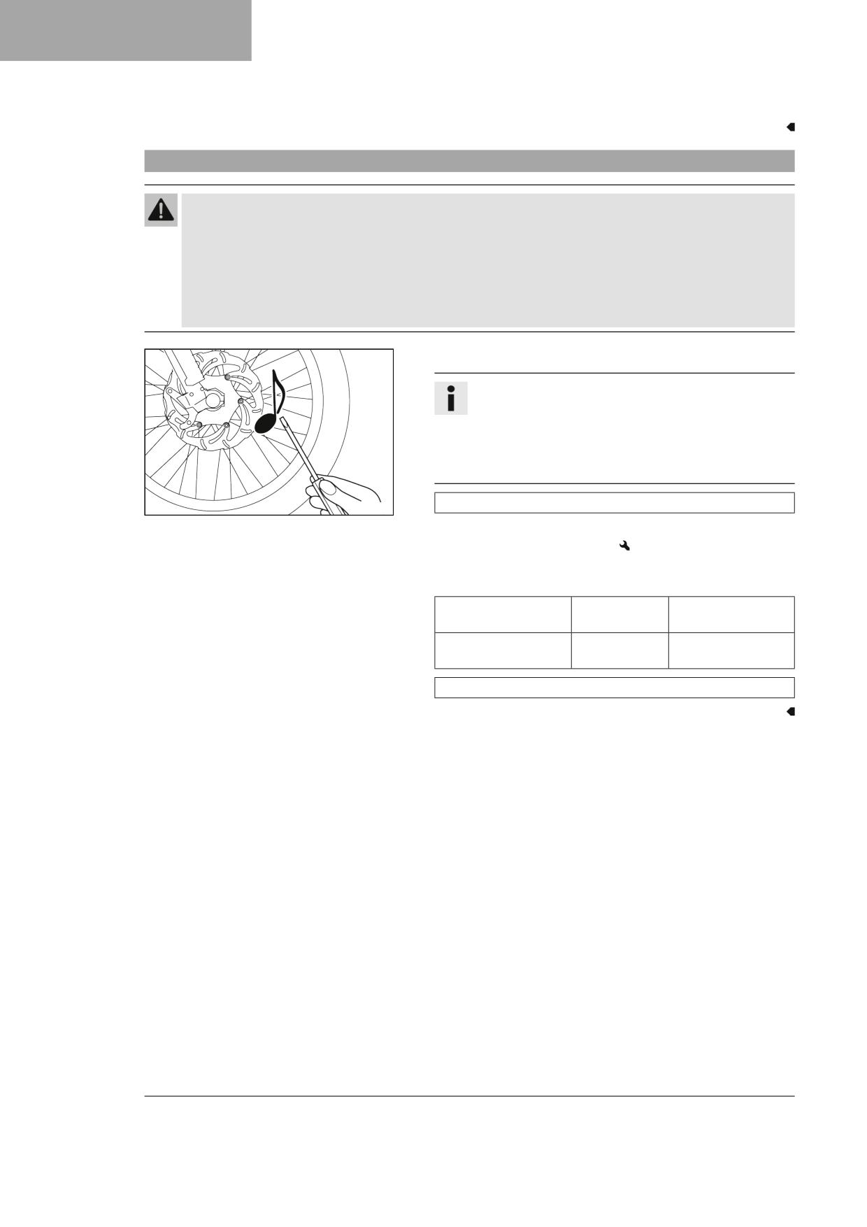
14
WHEELS, TIRES
- Mount the protection cap.
14.7
Checking spoke tension
Warning
Danger of accidents Incorrectly tensioned spokes impair the handling characteristic and result in secondary dam-
age.
The spokes break due to being overloaded if they are too tightly tensioned. If the tension in the spokes is too low,
then lateral and radial run-out will form in the wheel. Other spokes will become looser as a result.
- Check spoke tension regularly, and in particular on a new vehicle. (Your authorized GASGAS Motorcycles work-
shop will be glad to help.)
- Strike each spoke briefly using a screwdriver blade.
Info
The frequency of the sound depends on the spoke length
and spoke diameter.
If you hear different tone frequencies from different spokes
of equal length and diameter, this is an indication of differ-
ent spoke tensions.
You should hear a high note.
400694-01
» If the spoke tension differs:
- Correct the spoke tension.
- Check the spoke torque.
Guideline
Spoke nipple, front
M4.5
6 Nm (4.4 lbf ft)
wheel
Spoke nipple, rear
M4.5
6 Nm (4.4 lbf ft)
wheel
Torque wrench kit (58429094000)
100
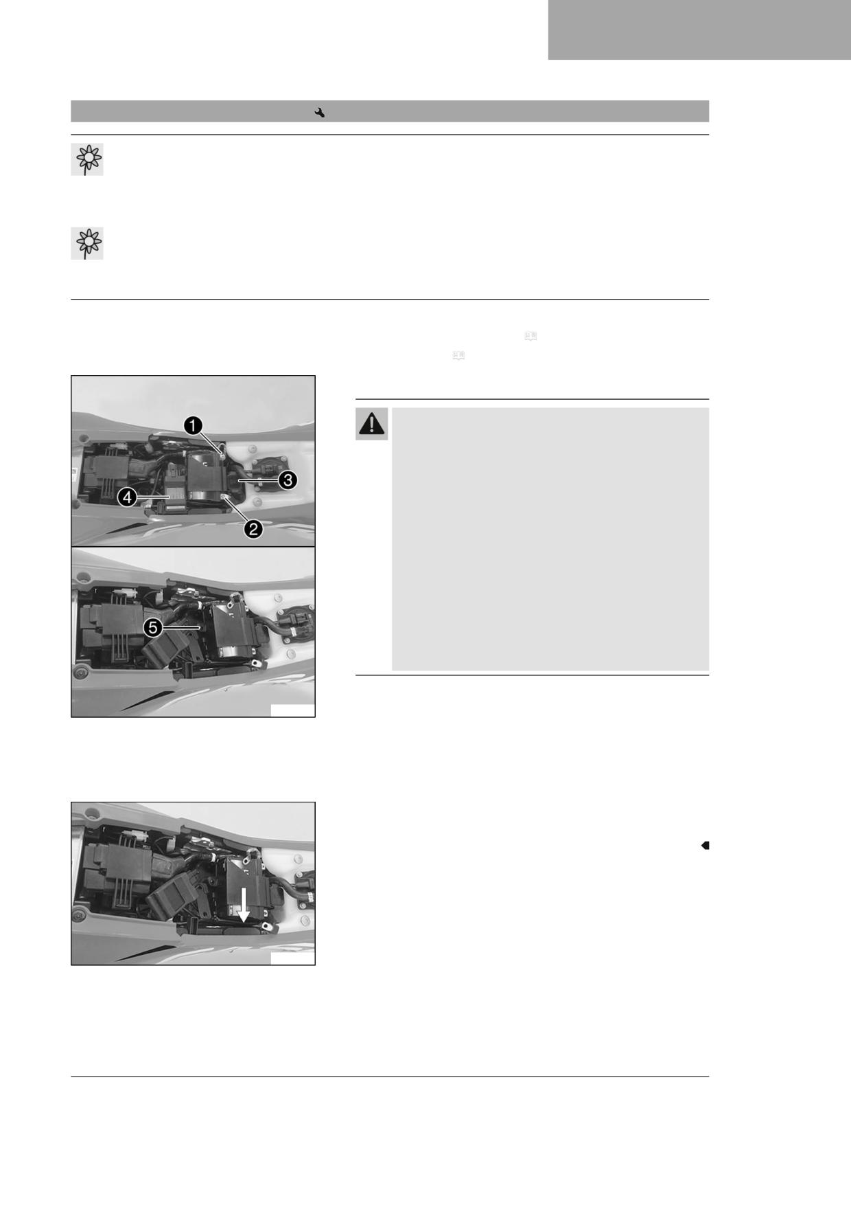
ELECTRICAL SYSTEM
15
15.1
Removing the 12-V battery
Note
Environmental hazard
12 V batteries contain environmentally hazardous materials.
– Do not dispose of 12 V batteries as household waste.
- Dispose of 12 V batteries at a collection point for used batteries.
Note
Environmental hazard Hazardous substances cause environmental damage.
- Dispose of oils, grease, filters, fuel, cleaning agents, brake fluid, etc., correctly and in compliance with the appli-
cable regulations.
Preparatory work
- Remove the air filter box cover. ( p. 63)
- Remove the seat. ( p. 62)
Main work
Warning
Risk of injury
12 V batteries contain harmful substances.
– Keep 12 V batteries out of the reach of children.
- Keep sparks and open flames away from 12 V batteries.
- Only charge 12 V batteries in well-ventilated rooms.
- Maintain a minimum clearance from inflammable
materials when charging 12 V batteries.
Minimum clearance
1 m (3 ft)
– Do not charge deeply discharged 12 V batteries if the
charge is already below the minimum voltage.
Minimum voltage before 9 V
the start of the charge
- Dispose of 12 V batteries correctly if they have less than
the minimum voltage.
- Disconnect negative cable 1 from the 12-V battery.
A01339-10
- Pull back positive terminal cover and disconnect positive cable 2
from the 12-V battery.
- Pull off starter relay 3 and OCU 4 and hang to the side.
- Unscrew battery holding bracket screw 5.
- Push battery holding bracket to the side and detach.
- Lift out the 12-V battery.
A01340-10
101
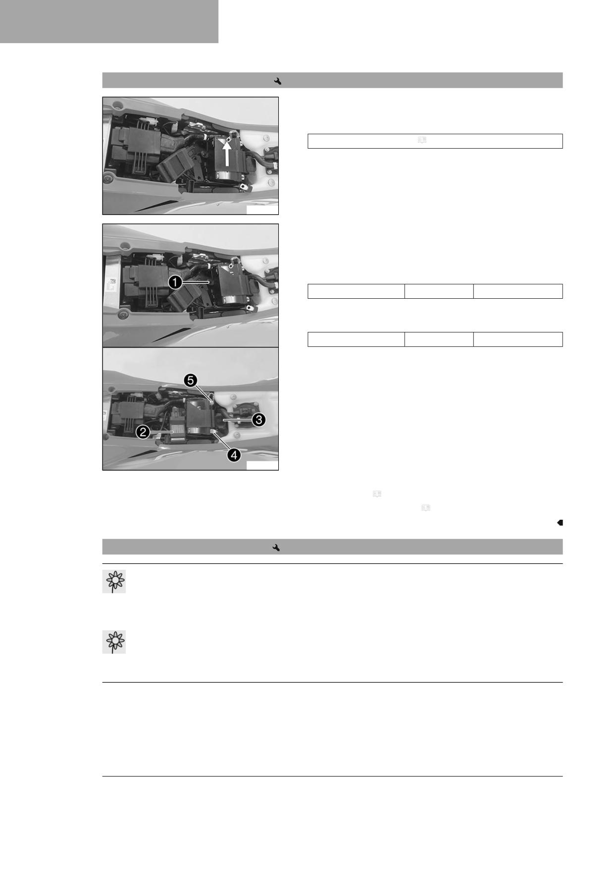
15
ELECTRICAL SYSTEM
15.2
Installing the 12-V battery
Main work
- Insert the 12-V battery into the battery compartment with the ter-
minals facing forward and secure with holding bracket.
12-V battery (HJTZ5S-FP-C) ( p. 137)
A01341-10
- Screw battery holding bracket screw 1 tight.
- Attach starter relay 2 and OCU 3 to the holding bracket.
- Connect positive cable 4 to the 12-V battery.
Guideline
Screw, battery terminal
M5
2.5 Nm (1.84 lbf ft)
– Connect negative cable 5 to the 12 V battery.
Guideline
Screw, battery terminal
M5
2.5 Nm (1.84 lbf ft)
A01343-10
Finishing work
- Mount the seat. ( p. 62)
- Install the air filter box cover. ( p. 64)
15.3
Charging the 12-V battery
Note
Environmental hazard
12 V batteries contain environmentally hazardous materials.
– Do not dispose of 12 V batteries as household waste.
- Dispose of 12 V batteries at a collection point for used batteries.
Note
Environmental hazard Hazardous substances cause environmental damage.
- Dispose of oils, grease, filters, fuel, cleaning agents, brake fluid, etc., correctly and in compliance with the appli-
cable regulations.
102
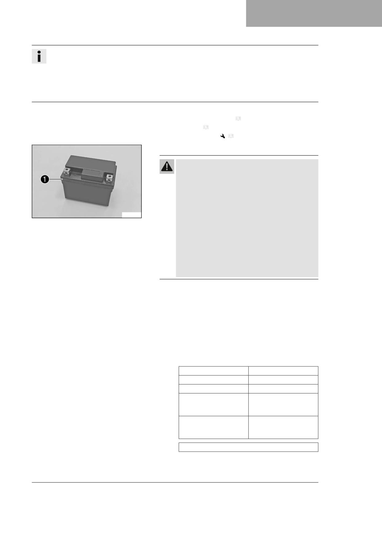
ELECTRICAL SYSTEM
15
Info
Even when there is no load on the 12-V battery, it discharges steadily each day.
The charging level and the method of charging are very important for the service life of the 12-V battery.
Rapid recharging with a high charging current shortens the service life of the battery.
If the 12-V battery is depleted by repeated starting, the 12-V battery must be charged immediately.
If the 12-V battery is left in a discharged state for an extended period, it will become deeply discharged and suffer a
loss of capacity, destroying the battery.
Preparatory work
- Remove the air filter box cover. ( p. 63)
- Remove the seat. ( p. 62)
- Remove the 12-V battery.
(
p. 101)
Main work
Warning
Risk of injury
12 V batteries contain harmful substances.
– Keep 12 V batteries out of the reach of children.
- Keep sparks and open flames away from 12 V batteries.
- Only charge 12 V batteries in well-ventilated rooms.
- Maintain a minimum clearance from inflammable
F01568-10
materials when charging 12 V batteries.
Minimum clearance
1 m (3 ft)
– Do not charge deeply discharged 12 V batteries if the
charge is already below the minimum voltage.
Minimum voltage before 9 V
the start of the charge
- Dispose of 12 V batteries correctly if they have less than
the minimum voltage.
- Check the battery voltage.
» Battery voltage: < 9 V
- Do not charge the 12-V battery.
- Replace the 12-V battery and dispose of the old 12-V bat-
tery properly.
» If the specifications have been met:
Battery voltage: ≥ 9 V
- Connect a battery charger to the 12-V battery. Switch on
the battery charger.
Guideline
Maximum charging voltage
14.4 V
Maximum charging current
3.0 A
Maximum charging time
12 h
Recharge the 12-V battery
6 months
regularly when the motor-
cycle is not being used
Ideal charging and storage
10 … 20 °C (50 … 68 °F)
temperature of the lithium-
ion battery
Battery charger (79629974000)
This battery charger tests whether the 12-V battery retains
its voltage. It is also impossible to overcharge the 12-V bat-
103

15
ELECTRICAL SYSTEM
tery with this battery charger. The charging time may be
longer at low temperatures.
This battery charger is only suitable for lithium iron phos-
phate batteries. Read the accompanying GASGAS Techni-
cal Accessories instructions.
Info
If the charging current, charging voltage, or
charging time is exceeded, the 12-V battery will be
destroyed.
If the 12-V battery is left in a discharged state for an
extended period, it will become deeply discharged
and suffer a loss of capacity, destroying the battery.
The 12-V battery is maintenance-free.
Never remove cover 1.
- Switch off the battery charger after charging and disconnect from
the 12-V battery.
Finishing work
- Install the 12-V battery.
(
p. 102)
– Mount the seat. ( p. 62)
- Install the air filter box cover. ( p. 64)
15.4
Changing the main fuse
Warning
Fire hazard Incorrect fuses overload the electrical system.
- Only use fuses with the required ampere value.
- Do not bypass or repair fuses.
Info
The main fuse protects all electrical power consumers of the vehicle.
Preparatory work
- Remove the air filter box cover. ( p. 63)
- Remove the seat. ( p. 62)
- Remove the fuel tank.
(
p. 70)
104

ELECTRICAL SYSTEM
15
Main work
- Take off protection caps 1.
- Remove faulty main fuse 2.
Info
A faulty fuse has a burned-out fuse wire A.
A spare fuse 3 is located in the starter relay.
- Insert a new main fuse.
Fuse (58011109120) ( p. 137)
- Check that the electrical system is functioning properly.
Tip
Insert a spare fuse so that it is available if needed.
- Mount the protection caps.
- Mount the starter relay onto the holder and route the cable.
A01380-10
Finishing work
- Install the fuel tank.
(
p. 71)
– Mount the seat. ( p. 62)
- Install the air filter box cover. ( p. 64)
15.5
Removing the headlight mask with the headlight
- Release screws 1.
- Slide the headlight mask up and swing it forward.
- Detach the brake line and wiring harness from the headlight mask.
T04630-01
(All US models)
- Disconnect plug-in connector 2 and take off the headlight
mask together with the headlight.
W00351-10
105
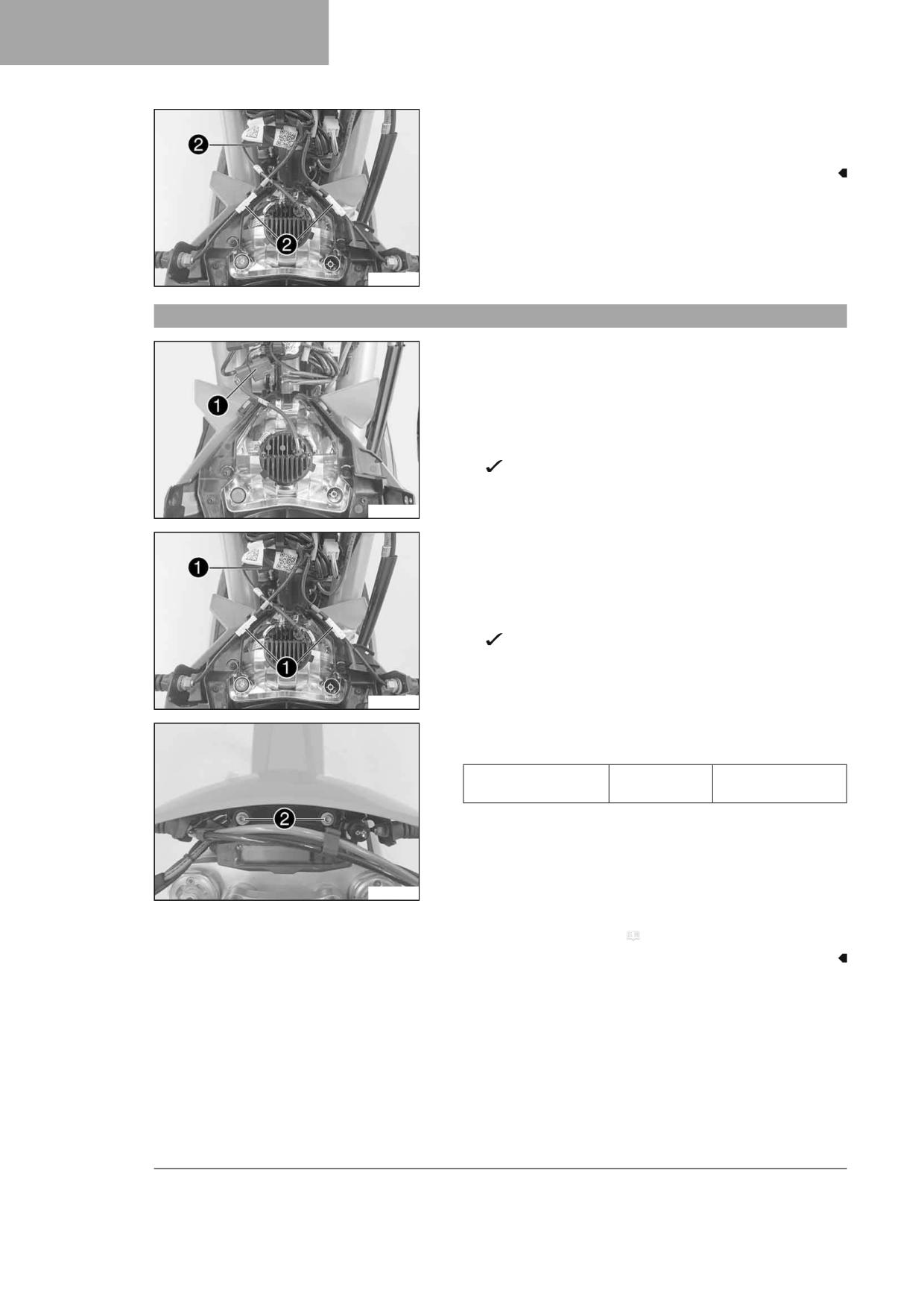
15
ELECTRICAL SYSTEM
(All EU models)
- Detach plug-in connectors 2 and take off the headlight mask
with the headlight.
W00350-10
15.6
Installing the headlight mask with the headlight
Main work
(All US models)
- Join plug-in connector 1.
- Position the brake line and wiring harness in the brake line
guide.
- Position the headlight mask.
The holding lugs engage in the fender.
W00351-11
(All EU models)
- Join plug-in connectors 1.
- Position the brake line and wiring harness in the brake line
guide.
- Position the headlight mask.
The holding lugs engage in the fender.
W00350-11
- Mount and tighten screws 2.
Guideline
Remaining nuts, chas-
M6
10 Nm (7.4 lbf ft)
sis
W00349-11
Finishing work
- Check the headlight setting. ( p. 107)
106
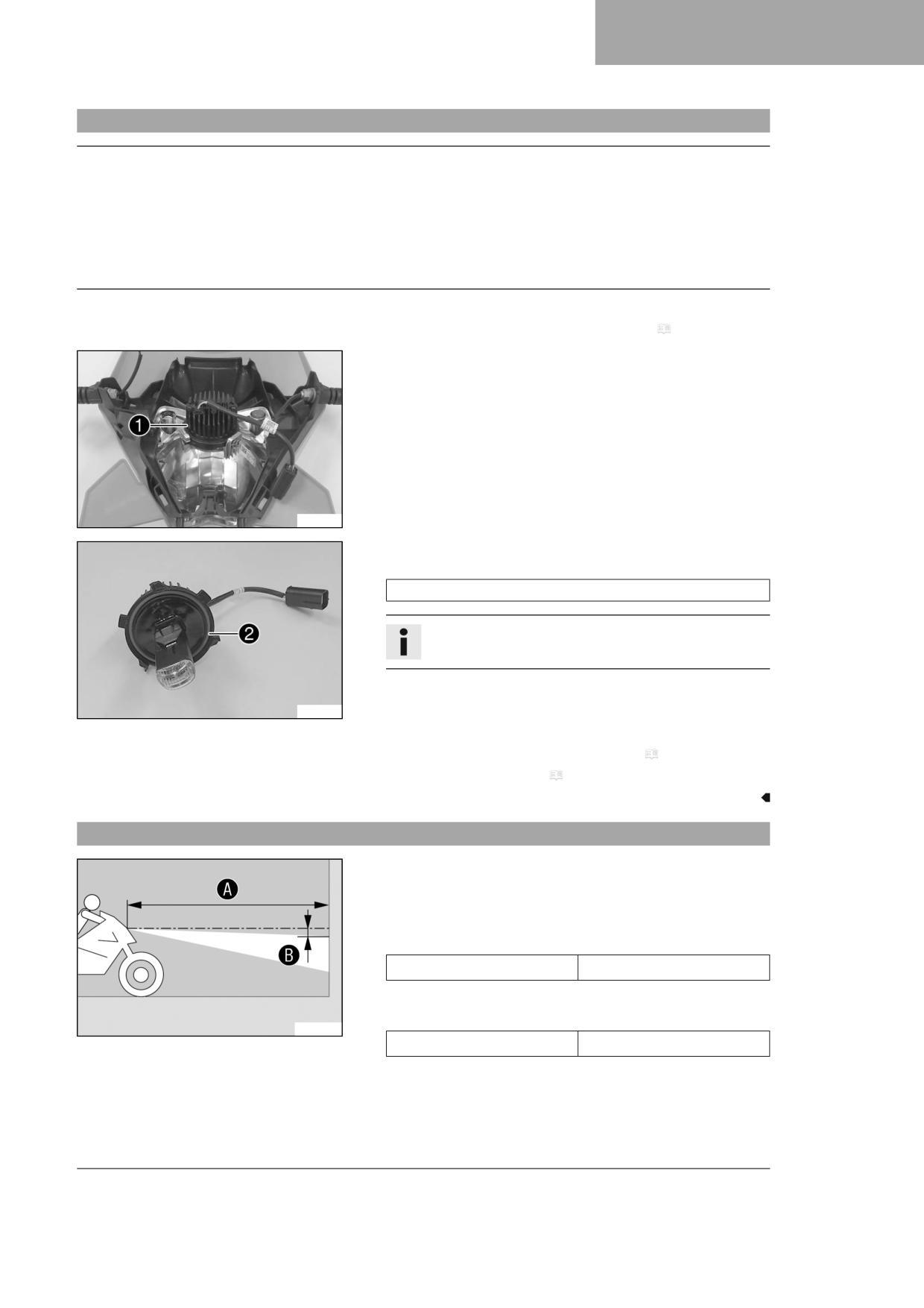
ELECTRICAL SYSTEM
15
15.7
Changing the headlight bulb
Note
Impairments to reflectors and lamps Grease on the reflector reduces the emitted light.
Grease on the bulb will evaporate due to the heat and be deposited on the reflector.
Grease residue on the bulb reduces heat dissipation and increases the heat of the bulb, thus reducing its service life.
- Clean and degrease the bulbs before mounting.
- Do not touch the bulbs with your bare hands.
Preparatory work
- Remove the headlight mask with the headlight. ( p. 105)
Main work
- Turn LED unit 1 counterclockwise all the way and take it out of the
reflector.
I00431-10
- Insert the LED unit into the reflector and turn it clockwise all the
way.
Headlight (LED)
Info
Ensure that O-ring 2 is seated properly.
I00432-10
Finishing work
- Install the headlight mask with the headlight. ( p. 106)
- Check the headlight setting. ( p. 107)
15.8
Checking the headlight setting
- Position the vehicle upright on a horizontal surface in front of a light
wall and make a marking at the height of the center of the low beam
headlight.
- Make another mark at a distance B under the first marking.
Guideline
5 cm (2 in)
Distance B
– Position the vehicle vertically at a distance A away from the wall.
Guideline
400726-10
5 m (16 ft)
Distance A
– The rider now sits down on the motorcycle.
- Switch on the low beam.
- Check the headlight setting.
107

15
ELECTRICAL SYSTEM
The boundary between light and dark must be exactly on the
lower mark for a motorcycle with rider.
» If the boundary between light and dark does not meet specifica-
tions:
- Adjust headlight range. ( p. 108)
15.9
Adjusting the headlight range
Preparatory work
- Check the headlight setting. ( p. 107)
Main work
- Loosen screw 1.
- Adjust the headlight range by pivoting the headlight.
Guideline
The boundary between light and dark must be exactly on the
lower mark for a motorcycle with rider (instructions on how to
apply the mark: Checking the headlight setting).
V00369-10
Info
A change in weight on the vehicle may require a correction
of the headlight range.
- Tighten screw 1.
Finishing work
- Check the headlight setting. ( p. 107)
15.10
Changing the turn signal bulb (All EU models)
Note
Impairments to reflectors and lamps Grease on the reflector reduces the emitted light.
Grease on the bulb will evaporate due to the heat and be deposited on the reflector.
Grease residue on the bulb reduces heat dissipation and increases the heat of the bulb, thus reducing its service life.
- Clean and degrease the bulbs before mounting.
- Do not touch the bulbs with your bare hands.
108
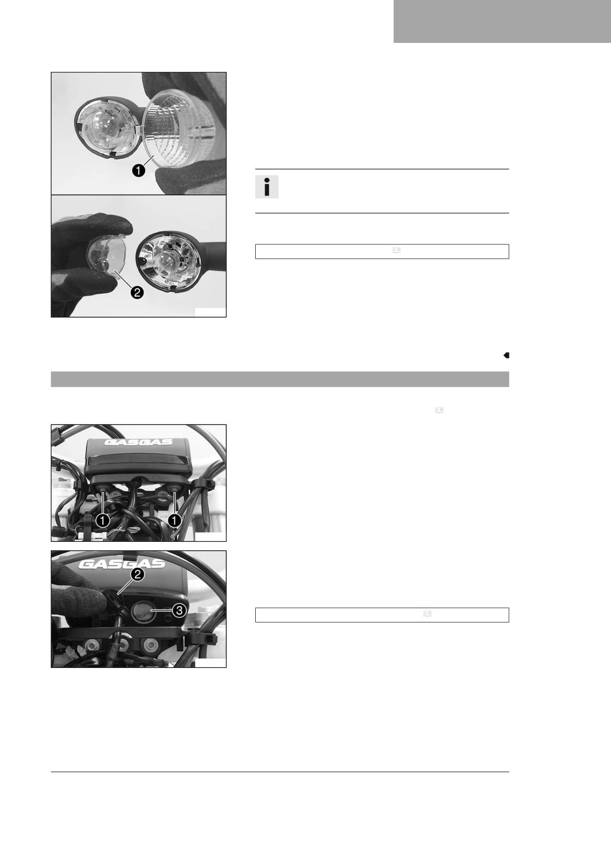
ELECTRICAL SYSTEM
15
Main work
- Remove the screw on the rear of the turn signal housing.
- Carefully remove turn signal glass 1.
- Lightly squeeze orange cap 2 in the area of the holding lugs and
take it off.
- Press the turn signal bulb lightly into the socket, turn it counter-
clockwise by about 30°, and pull it out of the socket.
Info
Do not touch the reflector with your fingers and keep it free
from grease.
- Press the new turn signal bulb carefully into the socket and turn it
clockwise until it stops.
Turn signal (R10W / socket BA15s) ( p. 137)
- Mount the orange cap.
- Position the turn signal glass.
- Insert the screw and first turn counterclockwise until it engages in
the thread with a small jerk. Tighten the screw lightly.
E00360-10
Finishing work
- Check that the turn signal system is functioning properly.
15.11
Changing the combination instrument battery
Preparatory work
- Remove the headlight mask with the headlight. ( p. 105)
Main work
- Remove screws 1 along with the washers.
- Pull the combination instrument upward out of the holder.
F03251-10
- Using a coin, turn protection cap 2 all the way counterclockwise
and take it off.
- Remove combination instrument battery 3.
- Insert the combination instrument with the label facing upward.
Combination instrument battery (CR 2430) ( p. 137)
- Check the O-ring of the protection cap for correct seating.
F03252-10
109
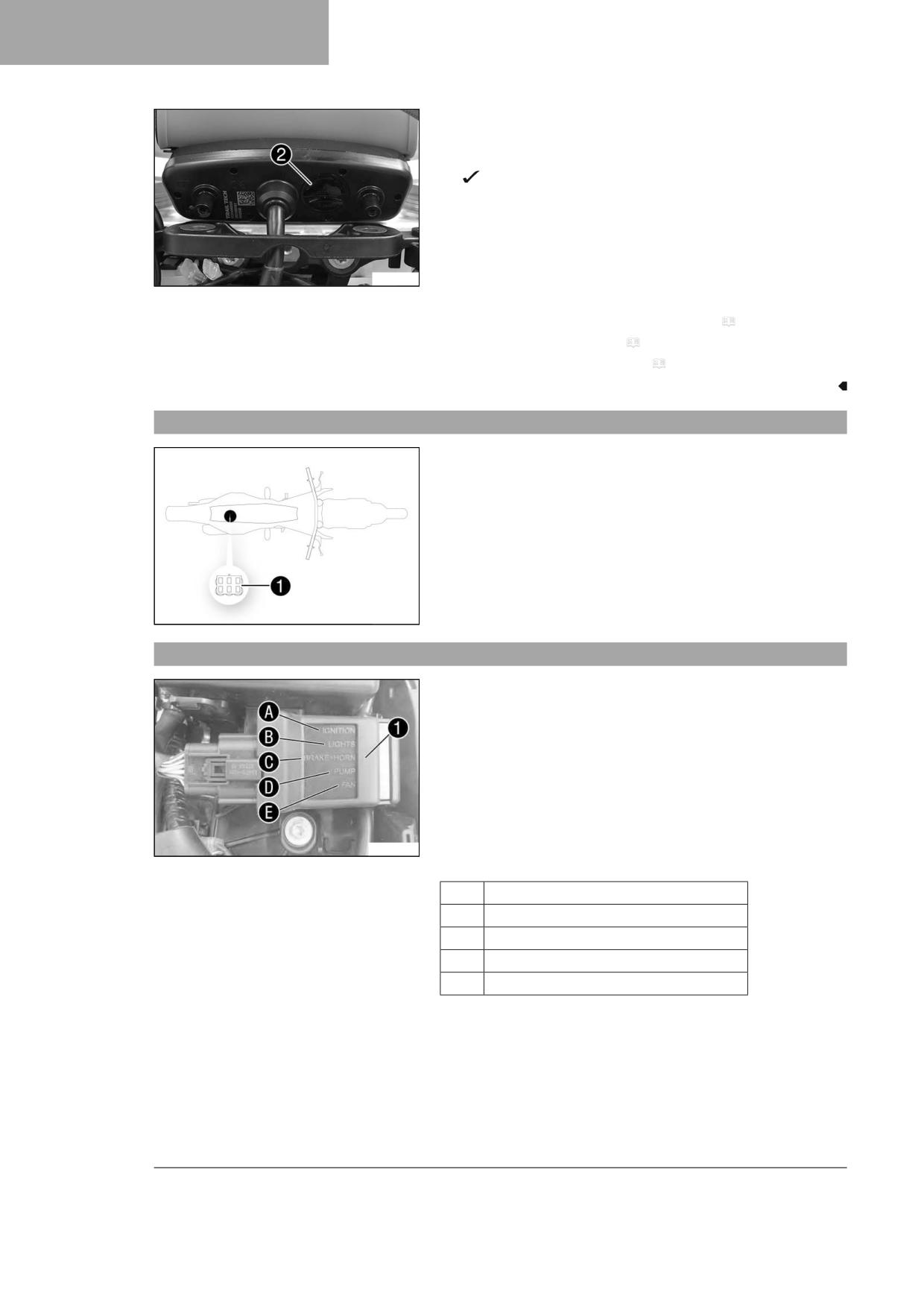
15
ELECTRICAL SYSTEM
- Position protection cap 2 and turn all the way clockwise using a
coin.
- Press any button on the combination instrument.
The combination instrument is activated.
- Position the combination instrument in the holder.
- Mount and tighten the screws with washers.
F03253-10
Finishing work
- Install the headlight mask with the headlight. ( p. 106)
- Check the headlight setting. ( p. 107)
- Set the combination instrument. ( p. 23)
15.12
Diagnostics connector
Diagnostics connector 1 is located under the seat.
F03736-10
15.13
OCU
OCU 1 is located under the seat.
The OCU replaces the electronic fuses and relays.
All outputs are switched depending on the signals of the voltage regula-
tor and ECU.
The outputs are deactivated individually in the event of overcurrent.
This enables easy error detection because the status of each output is
indicated via LED lights.
The OCU monitors the electronics system completely independently.
As soon as an indicated error is rectified, the status light of the OCU
W00331-10
changes from red to green.
Overview
A
Ignition
B
Light
C
Brake light + horn
D
Fuel pump
E
Radiator fan
110
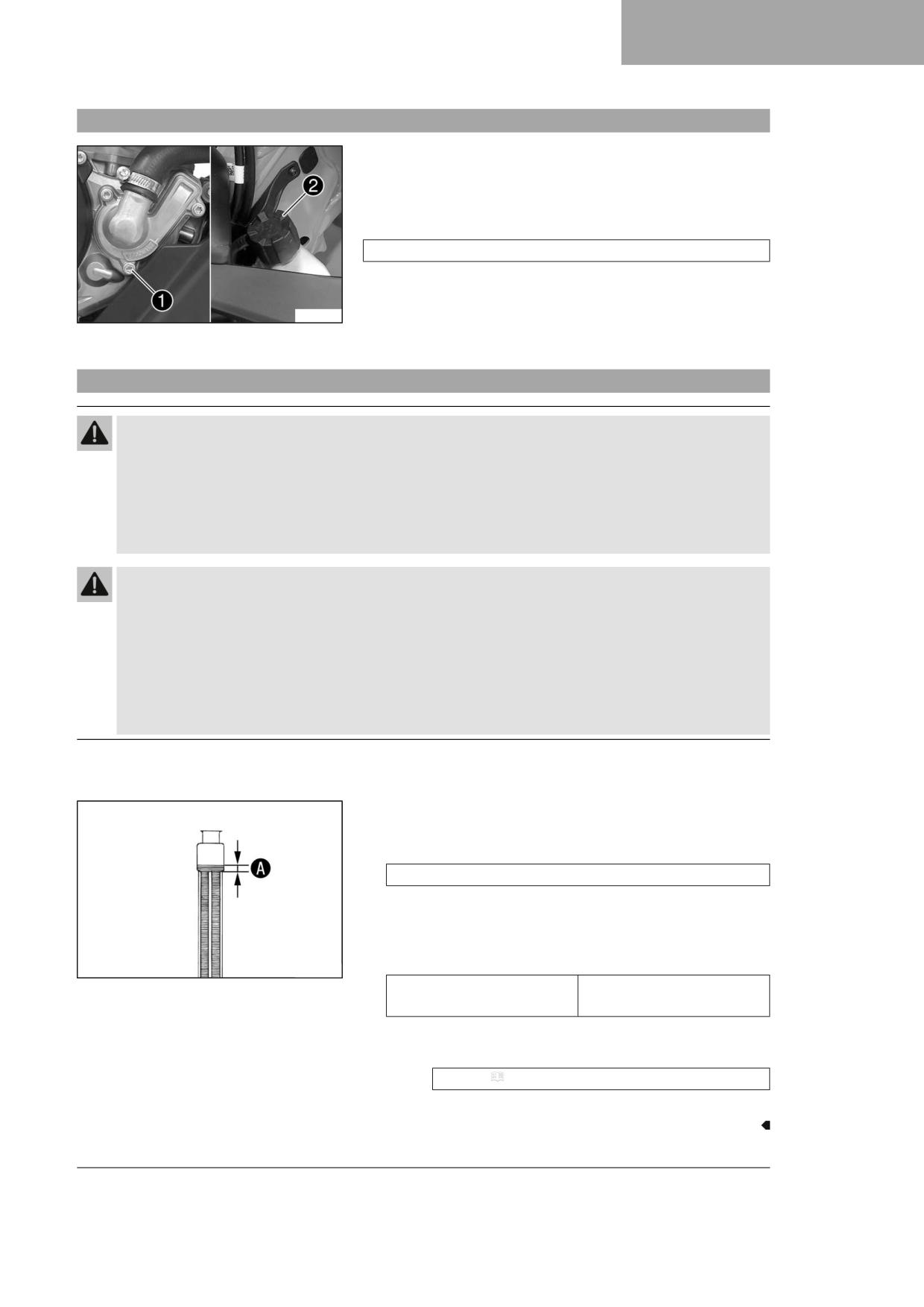
COOLING SYSTEM
16
16.1
Cooling system
Water pump 1 in the engine ensures forced circulation of the coolant.
The pressure resulting from the warming of the cooling system is reg-
ulated by a valve in radiator cap 2. This ensures that operating the
vehicle at the specified coolant temperature will not result in a risk of
malfunctions.
120 °C (248 °F)
Cooling is effected by the air stream.
The lower the speed, the less the cooling effect. Dirty cooling fins also
reduce the cooling effect.
F03739-10
Additional cooling is provided by the radiator fan, which is activated on a
temperature-dependent basis.
16.2
Checking the antifreeze and coolant level
Warning
Danger of scalding During motorcycle operation, the coolant gets hot and is under pressure.
- Do not open the radiator, the radiator hoses or other cooling system components if the engine or the cooling
system are at operating temperature.
- Allow the cooling system and the engine to cool down before you open the radiator, the radiator hoses or
other components of the cooling system.
- In the event of scalding, rinse the area affected immediately with lukewarm water.
Warning
Danger of poisoning Coolant is harmful to health.
- Keep coolant out of the reach of children.
- Do not allow coolant to come into contact with the skin, the eyes and clothing.
- Consult a doctor immediately if coolant is swallowed.
- Rinse the affected area immediately with plenty of water in the event of contact with the skin.
- Rinse eyes thoroughly with water and consult a doctor immediately if coolant gets into the eyes.
- Change clothing if coolant spills onto your clothing.
Condition
The engine is cold.
- Stand the motorcycle upright on a horizontal surface.
- Remove the radiator cap.
- Check the antifreeze in the coolant.
-25 … -45 °C (-13 … -49 °F)
» If the antifreeze in the coolant does not match the specified
value:
- Correct the antifreeze in the coolant.
- Check the coolant level in the radiator.
400243-10
10 mm (0.39 in)
Coolant level A above the
radiator fins
» If the coolant level does not match the specified value:
- Correct the coolant level.
Coolant ( p. 142)
- Mount the radiator cap.
111

16
COOLING SYSTEM
16.3
Checking the coolant level
Warning
Danger of scalding During motorcycle operation, the coolant gets hot and is under pressure.
- Do not open the radiator, the radiator hoses or other cooling system components if the engine or the cooling
system are at operating temperature.
- Allow the cooling system and the engine to cool down before you open the radiator, the radiator hoses or
other components of the cooling system.
- In the event of scalding, rinse the area affected immediately with lukewarm water.
Warning
Danger of poisoning Coolant is harmful to health.
- Keep coolant out of the reach of children.
- Do not allow coolant to come into contact with the skin, the eyes and clothing.
- Consult a doctor immediately if coolant is swallowed.
- Rinse the affected area immediately with plenty of water in the event of contact with the skin.
- Rinse eyes thoroughly with water and consult a doctor immediately if coolant gets into the eyes.
- Change clothing if coolant spills onto your clothing.
Condition
The engine is cold.
- Stand the motorcycle upright on a horizontal surface.
- Remove the radiator cap.
- Check the coolant level in the radiator.
10 mm (0.39 in)
Coolant level A above the
radiator fins
» If the coolant level does not match the specified value:
- Correct the coolant level.
400243-10
Coolant ( p. 142)
- Mount the radiator cap.
16.4
Draining the coolant
Warning
Danger of scalding During motorcycle operation, the coolant gets hot and is under pressure.
- Do not open the radiator, the radiator hoses or other cooling system components if the engine or the cooling
system are at operating temperature.
- Allow the cooling system and the engine to cool down before you open the radiator, the radiator hoses or
other components of the cooling system.
- In the event of scalding, rinse the area affected immediately with lukewarm water.
112
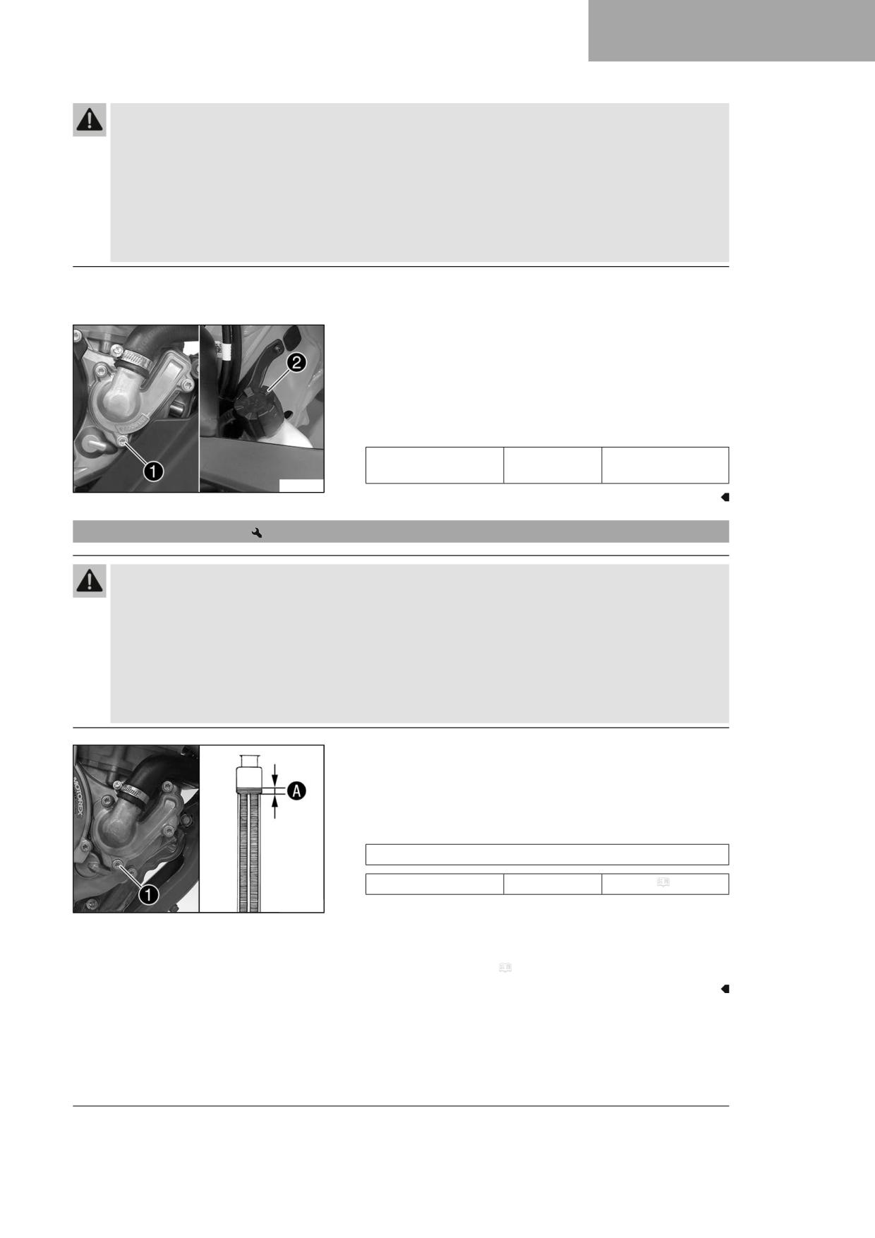
COOLING SYSTEM
16
Warning
Danger of poisoning Coolant is harmful to health.
- Keep coolant out of the reach of children.
- Do not allow coolant to come into contact with the skin, the eyes and clothing.
- Consult a doctor immediately if coolant is swallowed.
- Rinse the affected area immediately with plenty of water in the event of contact with the skin.
- Rinse eyes thoroughly with water and consult a doctor immediately if coolant gets into the eyes.
- Change clothing if coolant spills onto your clothing.
Condition
The engine is cold.
- Position the motorcycle upright.
- Place an appropriate container under the water pump cover.
- Remove screw 1. Take off radiator cap 2.
- Completely drain the coolant.
- Mount and tighten screw 1 with a new seal ring.
Guideline
Screw, water pump
M6
10 Nm (7.4 lbf ft)
cover
F03739-10
16.5
Refilling coolant
Warning
Danger of poisoning Coolant is harmful to health.
- Keep coolant out of the reach of children.
- Do not allow coolant to come into contact with the skin, the eyes and clothing.
- Consult a doctor immediately if coolant is swallowed.
- Rinse the affected area immediately with plenty of water in the event of contact with the skin.
- Rinse eyes thoroughly with water and consult a doctor immediately if coolant gets into the eyes.
- Change clothing if coolant spills onto your clothing.
Main work
- Make sure that the screw 1 is tightened.
- Stand the vehicle upright.
- Pour coolant in up to measurement A above the radiator fins.
Guideline
10 mm (0.39 in)
Coolant
0.95 l (1 qt.)
Coolant ( p. 142)
F03255-10
- Refit the radiator cap.
Finishing work
- Take a short test ride.
- Check the coolant level. ( p. 112)
113
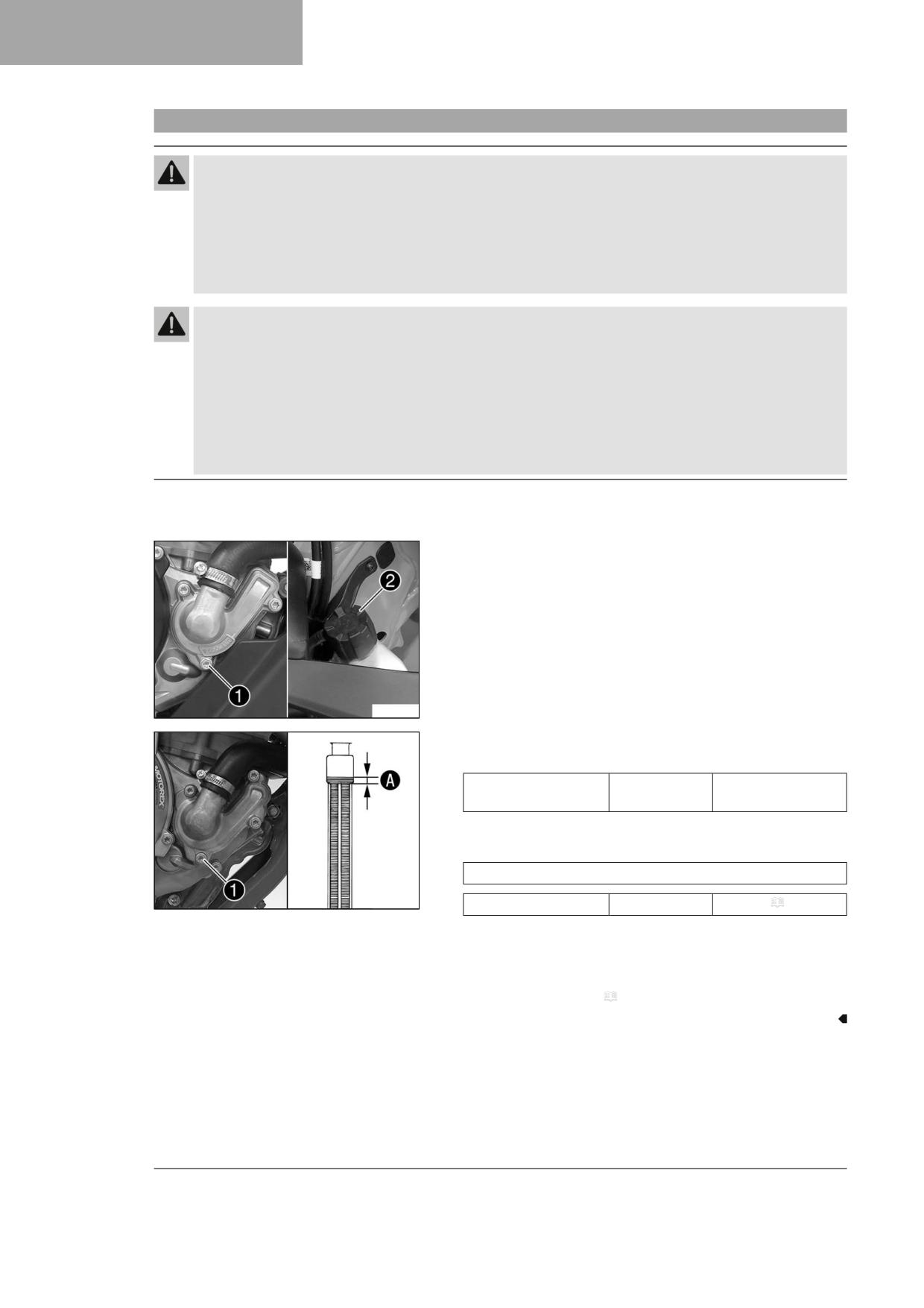
16
COOLING SYSTEM
16.6
Changing the coolant
Warning
Danger of scalding During motorcycle operation, the coolant gets hot and is under pressure.
- Do not open the radiator, the radiator hoses or other cooling system components if the engine or the cooling
system are at operating temperature.
- Allow the cooling system and the engine to cool down before you open the radiator, the radiator hoses or
other components of the cooling system.
- In the event of scalding, rinse the area affected immediately with lukewarm water.
Warning
Danger of poisoning Coolant is harmful to health.
- Keep coolant out of the reach of children.
- Do not allow coolant to come into contact with the skin, the eyes and clothing.
- Consult a doctor immediately if coolant is swallowed.
- Rinse the affected area immediately with plenty of water in the event of contact with the skin.
- Rinse eyes thoroughly with water and consult a doctor immediately if coolant gets into the eyes.
- Change clothing if coolant spills onto your clothing.
Condition
The engine is cold.
Main work
- Position the motorcycle upright.
- Place an appropriate container under the water pump cover.
- Remove screw 1. Take off radiator cap 2.
- Completely drain the coolant.
F03739-10
- Mount and tighten screw 1 with a new seal ring.
Guideline
Screw, water pump
M6
10 Nm (7.4 lbf ft)
cover
- Pour coolant in up to level A above the radiator fins.
Guideline
10 mm (0.39 in)
F03255-10
Coolant
0.95 l (1 qt.)
Coolant ( p. 142)
– Mount radiator cap 2.
Finishing work
- Go for a short test ride.
- Check the coolant level. ( p. 112)
114

TUNING THE ENGINE
17
17.1
Checking the play in the throttle cable
- Check the throttle grip for smooth operation.
- Move the handlebar to the straight-ahead position. Turn the throt-
tle grip back and forth slightly and determine the play in throttle
cable A.
Play in throttle cable
3 … 5 mm (0.12 … 0.2 in)
» If the throttle cable play does not meet the specified value:
- Adjust the play in the throttle cable.
(
p. 115)
– Push the cold start button in all the way.
400192-11
When the throttle grip is turned forward, the cold start button
returns to its original position.
» If the cold start button does not return to its original position:
- Adjust the play in the throttle cable.
(
p. 115)
Danger
Danger of poisoning Exhaust gases are toxic and inhaling
them may result in unconsciousness and death.
- Always make sure there is sufficient ventilation when
running the engine.
- Use effective exhaust extraction when starting or run-
ning the engine in an enclosed space.
- Start the engine and let it run at idle speed. Move the handlebar to
and fro over the entire steering range.
The idle speed must not change.
» If the idle speed changes:
- Adjust the play in the throttle cable.
(
p. 115)
17.2
Adjusting the play in the throttle cable
Info
If the correct routing of the throttle cables has already been secured, the fuel tank does not need to be removed.
Preparatory work
- Remove the air filter box cover. ( p. 63)
- Remove the seat. ( p. 62)
- Remove the fuel tank.
(
p. 70)
– Check the throttle cable routing. ( p. 78)
115
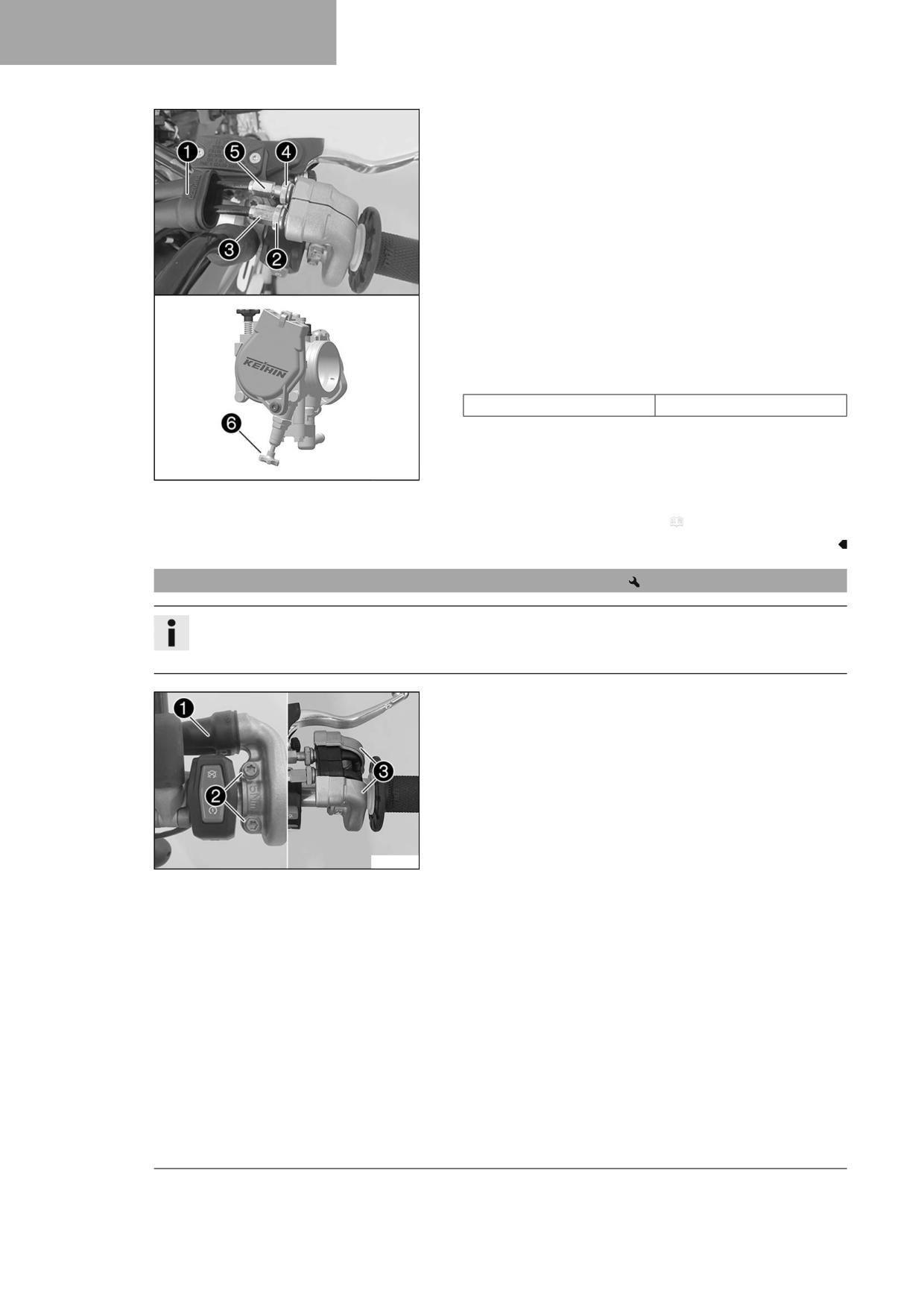
17
TUNING THE ENGINE
Main work
- Move the handlebar to the straight-ahead position.
- Push back sleeve 1.
- Loosen nut 2.
- Turn adjusting screw 3 in as far as possible.
- Loosen nut 4.
- Push cold start button 6 all the way to the stop.
- Turn adjusting screw 5 so that the cold start button moves to the
basic position when the throttle grip is turned to the front.
- Tighten nut 4.
- Turn adjusting screw 3 so that there is play in the throttle cable at
the throttle grip.
Guideline
Play in throttle cable
3 … 5 mm (0.12 … 0.2 in)
– Tighten nut 2.
- Slide on sleeve 1.
A01346-10
- Check the throttle grip for smooth operation.
Finishing work
- Check the play in the throttle cable. ( p. 115)
17.3
Adjusting the characteristic map of the throttle response
Info
On the throttle grip, the characteristic map of the throttle response is changed by changing the guide plate.
A guide plate with a different characteristic map is supplied.
Main work
- Push back sleeve 1.
- Remove screws 2 and half-shells 3.
- Detach the throttle cables and take off the grip tube.
A01348-10
116
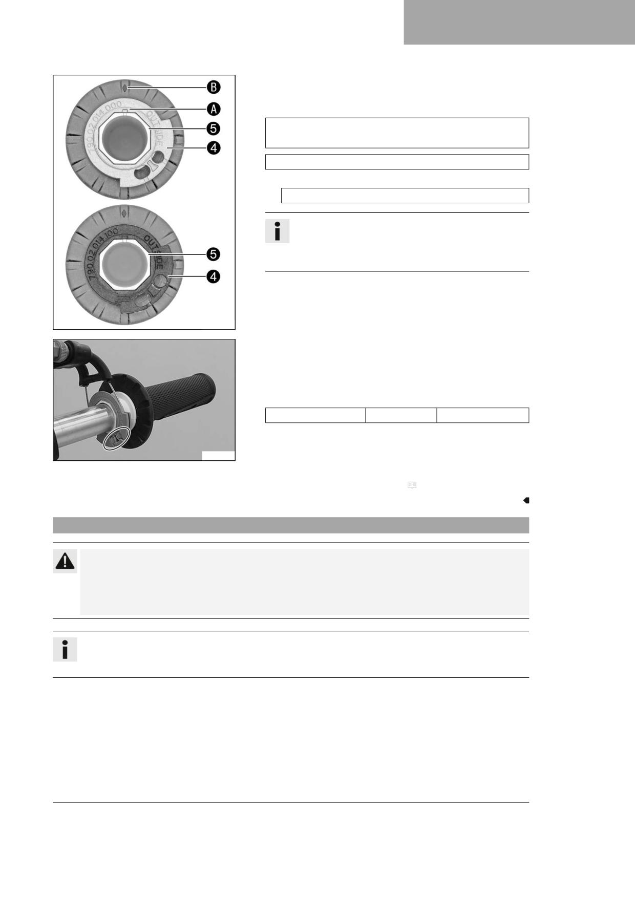
TUNING THE ENGINE
17
– Remove guide plate 4 from handle tube 5.
- Position the required guide plate on the grip tube.
Guideline
The label OUTSIDE must be visible. Marking A must be posi-
tioned at marking B.
Grey guide plate (79002014000)
Alternative 1
Black guide plate (79002014100)
Info
The gray guide plate opens the throttle valve more slowly.
The black guide plate opens the throttle valve more quickly.
The gray guide plate is mounted upon delivery.
102246-10
- Clean the outside of the handlebar and the inside of the grip tube.
Mount the grip tube on the handlebar.
- Attach the throttle cables to the guide plate and route correctly.
- Position half-shells 3, mount and tighten screws 2.
Guideline
Screw, throttle grip
M6
5 Nm (3.7 lbf ft)
– Slide on sleeve 1 and check the throttle grip for ease of move-
ment.
A01344-10
Finishing work
- Check the play in the throttle cable. ( p. 115)
17.4
Changing the mapping (optional)
Caution
Voiding of the government approval for road use and the insurance coverage If the combination switch is
mounted, the vehicle’s road permit, if any, expires.
- Only operate the vehicle in closed-off areas remote from public road traffic if the combination switch is
installed.
Info
Traction control can be activated additionally using button TC.
The mapping can also be changed during the ride.
117
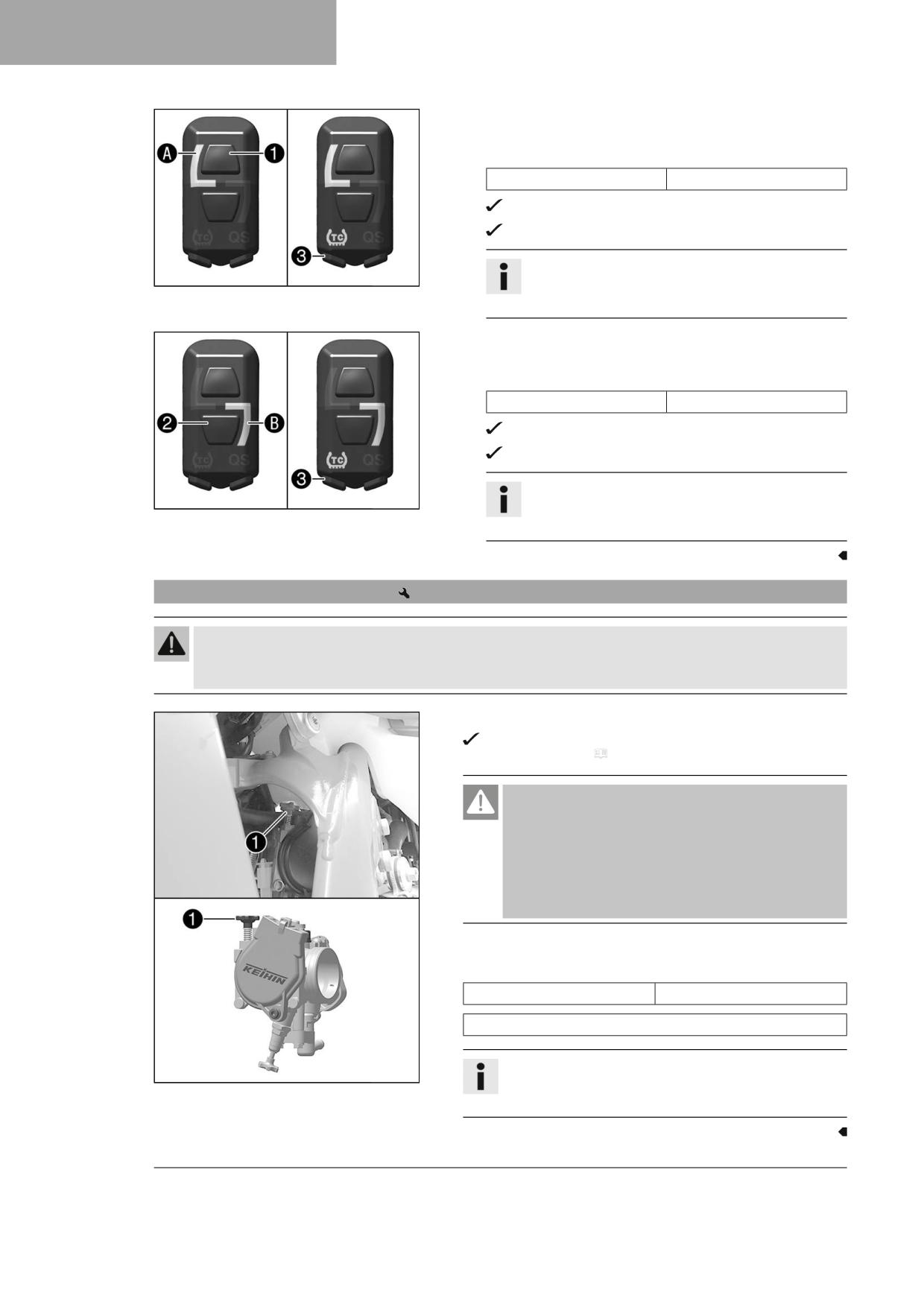
17
TUNING THE ENGINE
Activating STANDARD mapping:
- Press button 1.
Guideline
Engine speed
< 4,000 rpm
The indicator lamp A lights up.
STANDARD - balanced response
Info
F03762-10
Traction control can be activated additionally using TC
button 3.
Activating ADVANCED mapping:
- Press button 2.
Guideline
Engine speed
< 4,000 rpm
The indicator lamp B lights up.
ADVANCED - direct response
Info
F03763-10
Traction control can be activated additionally using TC
button 3.
17.5
Adjusting the idle speed
Warning
Danger of accidents The engine may go out spontaneously if the idle speed is set too low.
- Set the idle speed to the specified value. (Your authorized GASGAS Motorcycles workshop will be glad to help.)
- Run the engine until warm.
The cold start button is deactivated - The cold start button is in
its basic position. ( p. 19)
Danger
Danger of poisoning Exhaust gases are toxic and inhaling
them may result in unconsciousness and death.
- Always make sure there is sufficient ventilation when
running the engine.
- Use effective exhaust extraction when starting or run-
ning the engine in an enclosed space.
- Adjust the idle speed by turning idle speed adjusting screw 1.
Guideline
Idle speed
1,800 … 1,900 rpm
Service hour counter with revolution counter (A54012920100)
Info
R06539-10
Turning counterclockwise lowers the idle speed.
Turning clockwise raises the idle speed.
118
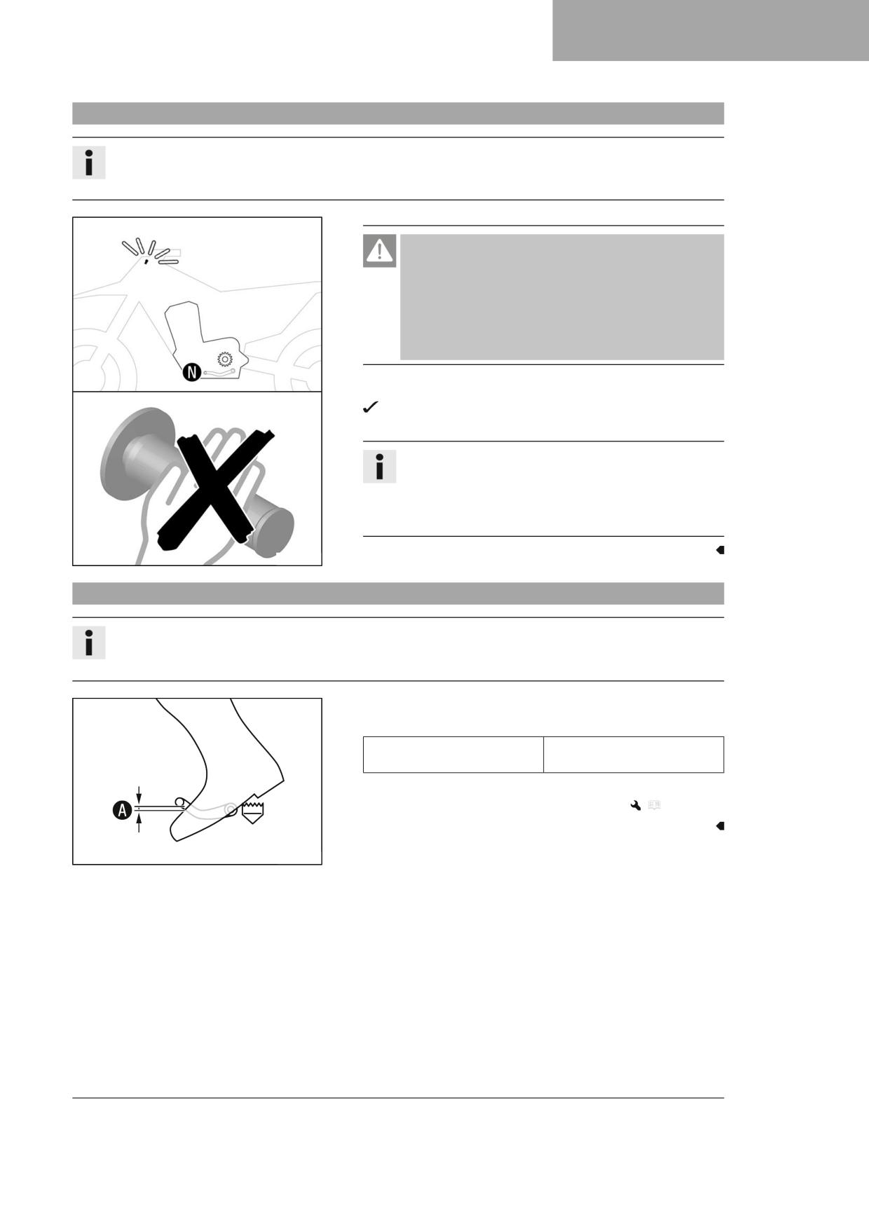
TUNING THE ENGINE
17
17.6
Programming the throttle valve position
Info
If the control unit detects that the throttle valve position at idle speed needs to be reprogrammed, then the mal-
function indicator lamp flashes 2x per second.
Danger
Danger of poisoning Exhaust gases are toxic and inhaling
them may result in unconsciousness and death.
- Always make sure there is sufficient ventilation when
running the engine.
- Use effective exhaust extraction when starting or run-
ning the engine in an enclosed space.
- Allow the vehicle to run at idle speed.
The malfunction indicator lamp stops flashing once program-
ming is completed.
Info
If the engine becomes too warm, perform a cool-down ride
at medium speed.
After this, do not switch off the engine, but leave it running
at idle speed until the programming is finished.
H02263-10
17.7
Checking the basic position of the shift lever
Info
When driving, the shift lever must not touch the rider's boot when in the basic position.
When the shift lever keeps touching the boot, the transmission will be subject to an excessive load.
- Sit on the vehicle in the riding position and determine distance A
between the upper edge of your boot and the shift lever.
Gap between the shift lever
10 … 20 mm (0.39 … 0.79 in)
and the top of the boot
» If the distance does not meet specifications:
- Adjust the basic position of the shift lever.
(
p. 120)
400692-10
119
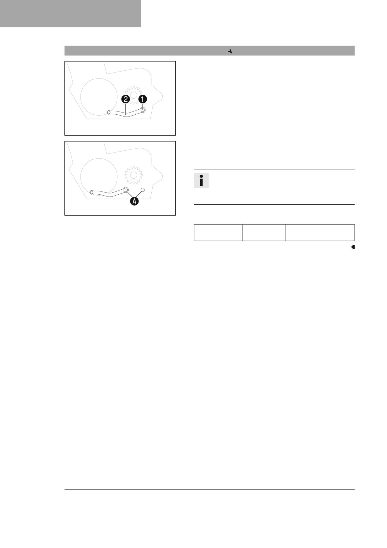
17
TUNING THE ENGINE
17.8
Adjusting the basic position of the shift lever
- Remove screw 1 with the washers and take off shift lever 2.
401950-12
- Clean gear teeth A of the shift lever and shift shaft.
- Mount the shift lever on the shift shaft in the required position and
engage gearing.
Info
The range of adjustment is limited.
The shift lever must not come into contact with any other
vehicle components during the shift procedure.
401951-10
- Mount the screw with the washers and tighten.
Guideline
Screw, shift lever
M6x16
14 Nm (10.3 lbf ft)
Loctite®243™
120
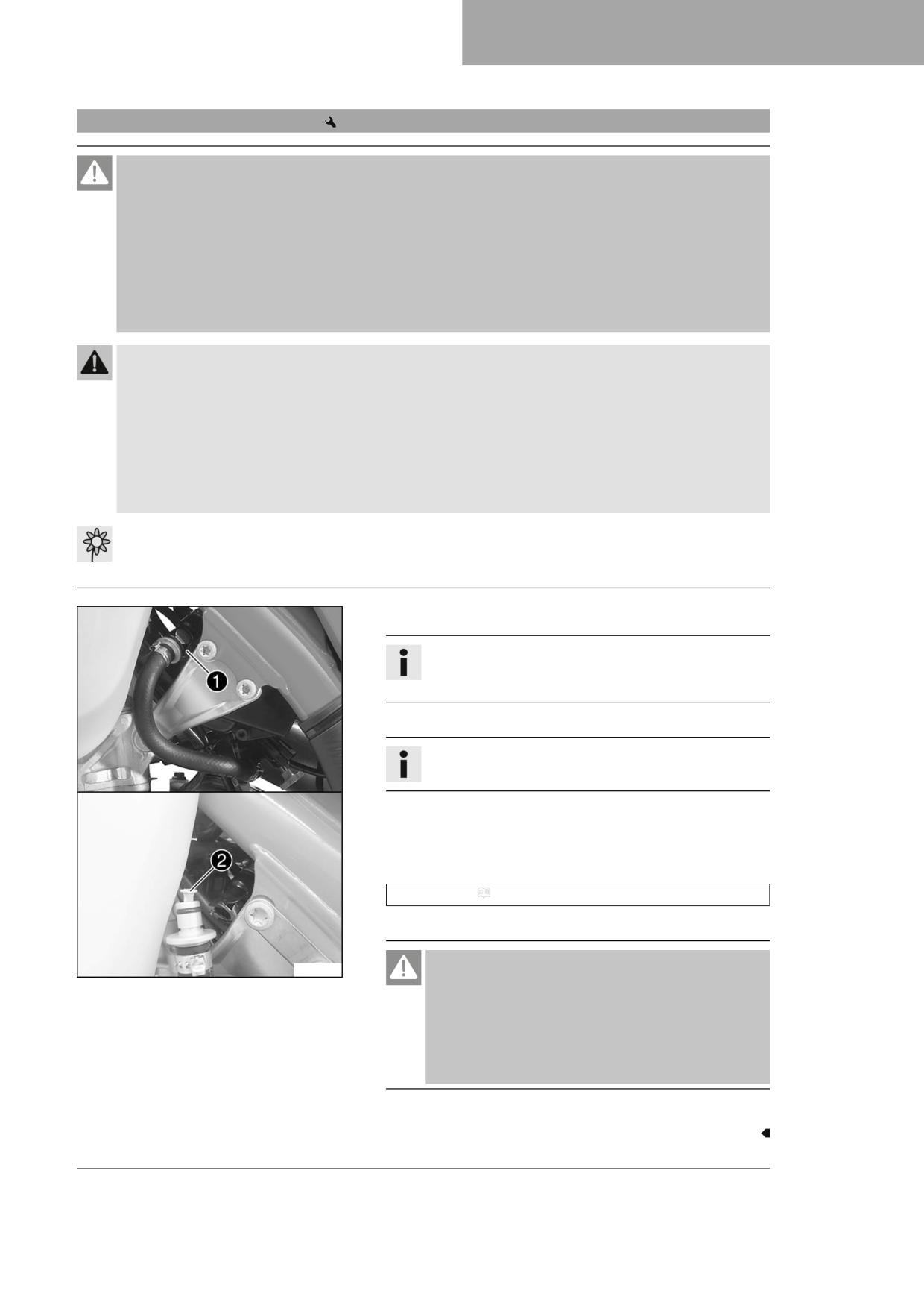
SERVICE WORK ON THE ENGINE
18
18.1
Changing the fuel screen
Danger
Fire hazard Fuel is highly flammable.
The fuel in the fuel tank expands when warm and can escape if overfilled.
- Do not fuel the vehicle in the vicinity of open flames or lit cigarettes.
- Switch off the engine for refueling.
- Make sure that no fuel is spilled; particularly not on hot parts of the vehicle.
- If any fuel is spilled, wipe it off immediately.
- Observe the specifications for refueling.
Warning
Danger of poisoning Fuel is harmful to health.
- Avoid skin, eye and clothing contact with fuel.
- Immediately consult a doctor if you swallow fuel.
- Do not inhale fuel vapors.
- Rinse the affected area immediately with plenty of water in the event of contact with the skin.
- Rinse the eyes thoroughly with water, and consult a doctor in case of fuel contact with the eyes.
- Change your clothing if fuel spills on them.
Note
Environmental hazard Improper handling of fuel is a danger to the environment.
- Do not allow fuel to enter the groundwater, the soil, or the sewage system.
- Clean quick release coupling 1 thoroughly with compressed air.
Info
Under no circumstances should dirt enter into the fuel line.
Dirt in the fuel line clogs the injection valve!
- Disconnect the quick release coupling.
Info
Remaining fuel may flow out of the fuel hose.
- Pull fuel screen 2 out of the connecting piece.
- Insert the new fuel screen all the way into the connecting piece.
- Spray silicone spray onto a lint-free cleaning cloth and lightly lubri-
cate the O-ring of the quick-release coupling.
Silicone spray ( p. 144)
- Join the quick release coupling.
Danger
A01353-10
Danger of poisoning Exhaust gases are toxic and inhaling
them may result in unconsciousness and death.
- Always make sure there is sufficient ventilation when
running the engine.
- Use effective exhaust extraction when starting or run-
ning the engine in an enclosed space.
- Start the engine and check the response.
121
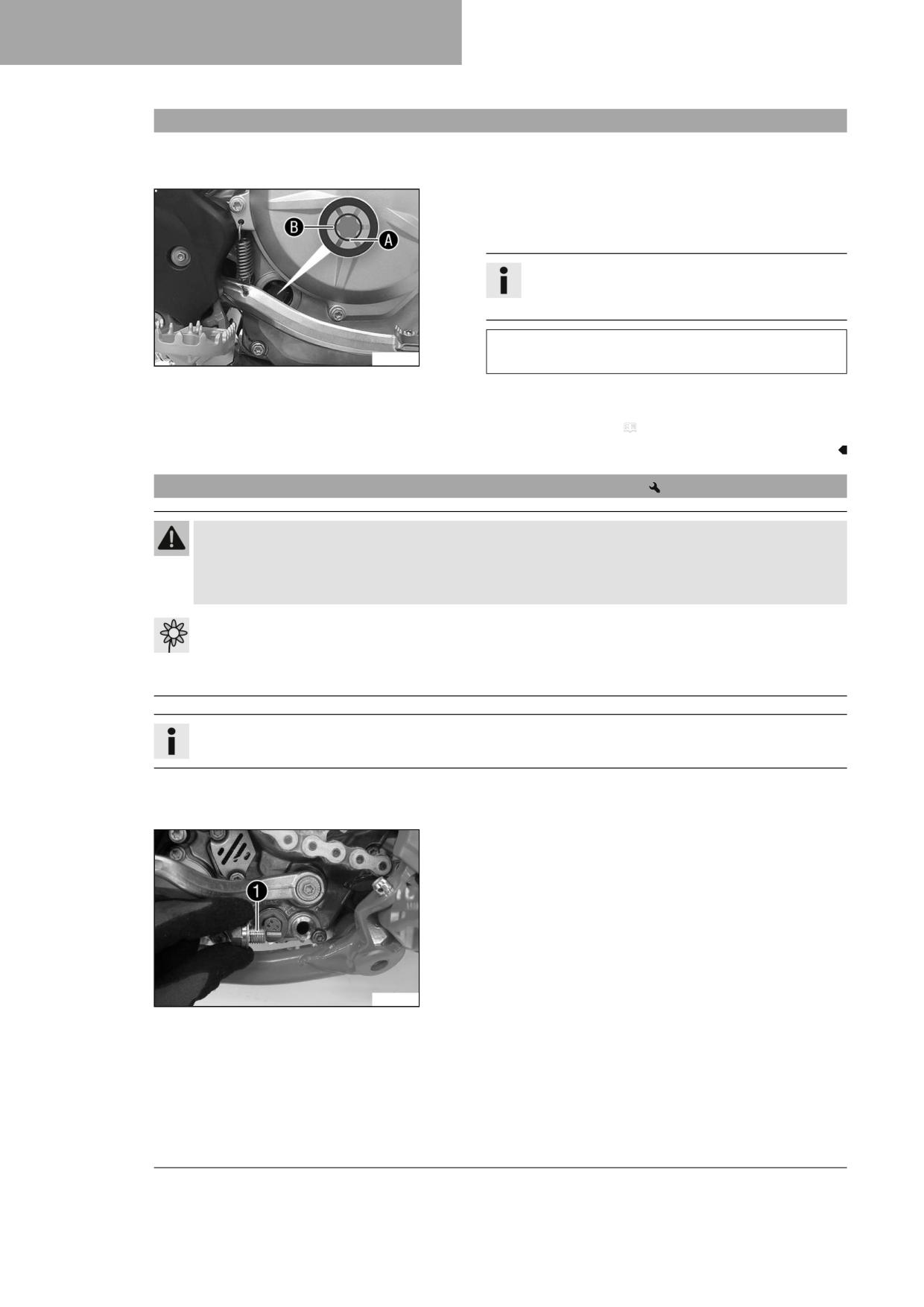
18
SERVICE WORK ON THE ENGINE
18.2
Checking the engine oil level
Preparatory work
- Stand the motorcycle upright on a horizontal surface.
Condition
The engine is at operating temperature.
- Check the engine oil level.
Info
After switching off the engine, wait one minute before
checking the level.
The engine oil is at a level between the lower edge A and
F03260-10
the middle of the level viewer B.
» If the engine oil is not up to the lower edge A of the level
viewer:
- Add engine oil. ( p. 125)
18.3
Changing the engine oil and oil filter, cleaning the oil screen
Warning
Danger of scalding Engine and gear oil get hot when the motorcycle is operated.
- Wear suitable protective clothing and safety gloves.
- In the event of scalding, rinse the area affected immediately with lukewarm water.
Note
Environmental hazard Hazardous substances cause environmental damage.
- Dispose of oils, grease, filters, fuel, cleaning agents, brake fluid, etc., correctly and in compliance with the appli-
cable regulations.
Info
Drain the engine oil with the engine at operating temperature.
Preparatory work
- Park the motorcycle on a level surface.
Main work
- Position an appropriate container under the engine.
- Remove oil drain plug 1 with the magnet and seal ring.
F03774-10
122
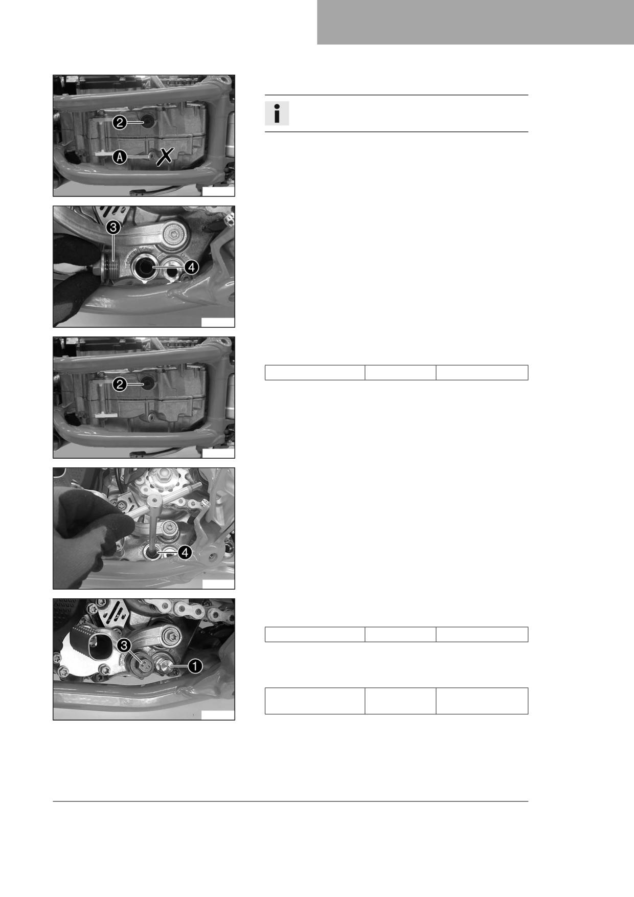
SERVICE WORK ON THE ENGINE
18
– Remove screw plug 2 with the O-ring.
Info
Do not remove screw A.
F03775-10
- Remove screw plug 3 with the long oil screen 4 and the O-rings.
- Allow the engine oil to drain completely.
- Thoroughly clean the parts and the sealing surfaces.
H05063-10
- Mount and tighten screw plug 2 with new O-ring.
Guideline
Screw plug, crankcase
M16x1.5
15 Nm (11.1 lbf ft)
F03775-11
- Position long oil screen 4 with the O-rings on a pin wrench.
- Position the pin wrench through the drill hole of the screw plug in
the opposite section of the engine case.
- Push the oil screen all the way into the engine case.
F03776-10
- Mount and tighten screw plug 3 with the O-ring.
Guideline
Screw plug, oil screen
M20x1.5
15 Nm (11.1 lbf ft)
– Mount and tighten oil drain plug 1 with the magnet and a new
seal ring.
Guideline
Oil drain plug with
M12x1.5
20 Nm (14.8 lbf ft)
magnet
H05065-10
123
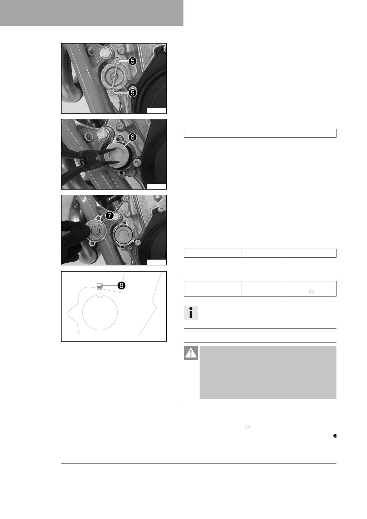
18
SERVICE WORK ON THE ENGINE
- Remove screws 5. Take off the oil filter cover with the O-ring.
H05066-10
- Pull oil filter 6 out of the oil filter housing.
Lock ring plier (51012011000)
- Allow the engine oil to drain completely.
- Thoroughly clean the parts and the sealing surface.
H05067-10
- Lay the motorcycle on its side and fill the oil filter housing to about
⅓ full with engine oil.
- Insert the new oil filter into the oil filter housing.
- Oil the O-ring of the oil filter cover and mount it together with oil
filter cover 7.
- Mount and tighten the screws.
Guideline
Screw, oil filter cover
M6x16
10 Nm (7.4 lbf ft)
H05068-10
- Stand the motorcycle upright.
- Remove filler plug 8 with the O-ring, and fill up with engine oil.
Engine oil
1.2 l (1.3 qt.)
Engine oil (SAE
10W/50) ( p. 142)
Info
Too little engine oil or poor-quality engine oil will result in
premature wear of the engine.
- Mount and tighten the filler plug together with the O-ring.
H01713-10
Danger
Danger of poisoning Exhaust gases are toxic and inhaling
them may result in unconsciousness and death.
- Always make sure there is sufficient ventilation when
running the engine.
- Use effective exhaust extraction when starting or run-
ning the engine in an enclosed space.
- Start the engine and check it for leaks.
Finishing work
- Check the engine oil level. ( p. 122)
124
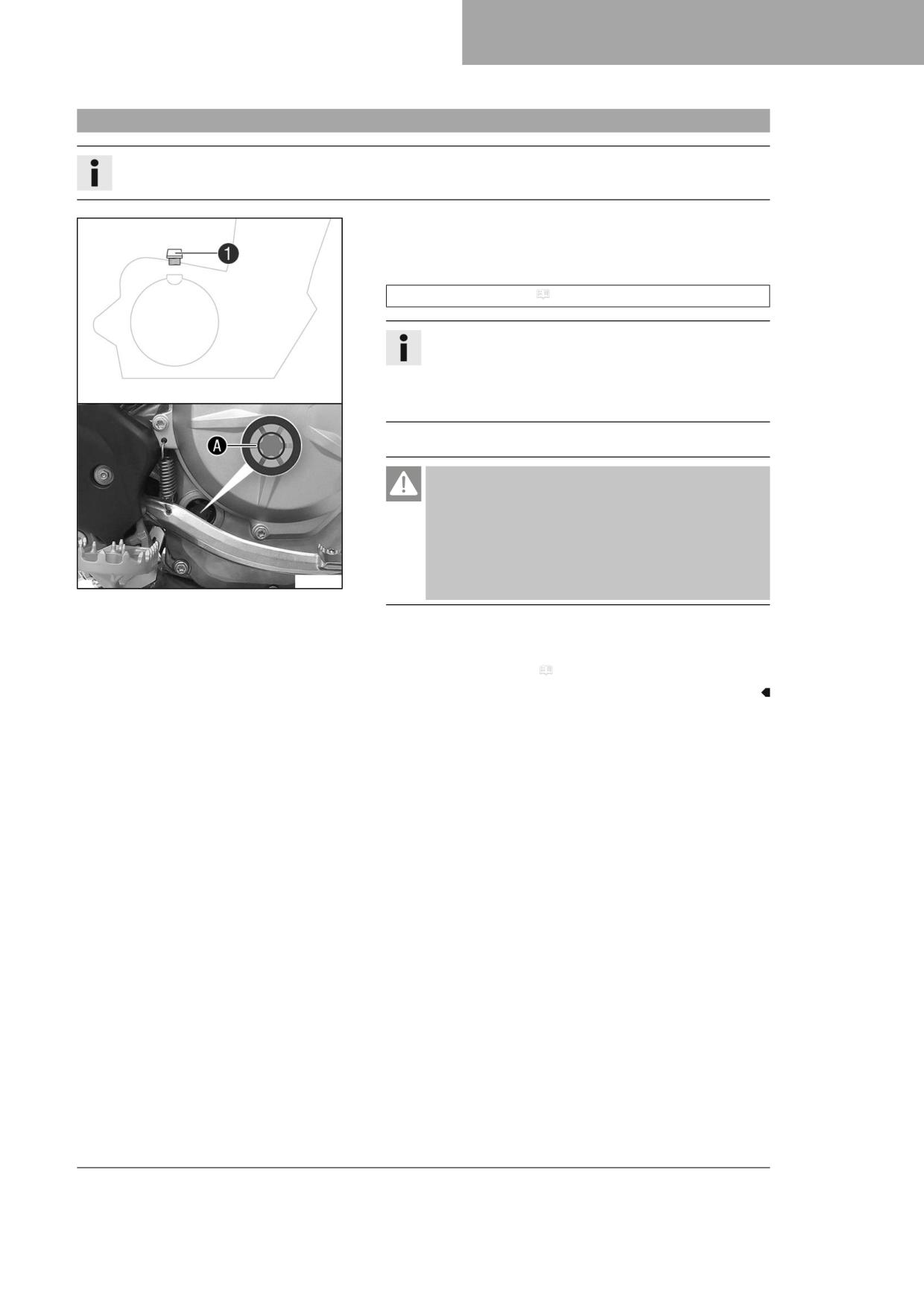
SERVICE WORK ON THE ENGINE
18
18.4
Adding engine oil
Info
Too little engine oil or poor-quality engine oil will result in premature wear of the engine.
Main work
- Remove oil filler plug 1 with the O-ring from the clutch cover.
- Fill engine oil to the middle A of the level viewer.
Engine oil (SAE 10W/50) ( p. 142)
Info
In order to achieve optimal engine oil performance, it is not
advisable to mix different engine oils.
GASGAS Motorcycles recommends changing the engine oil,
if necessary.
- Mount and tighten the filler plug together with the O-ring.
Danger
Danger of poisoning Exhaust gases are toxic and inhaling
them may result in unconsciousness and death.
- Always make sure there is sufficient ventilation when
running the engine.
- Use effective exhaust extraction when starting or run-
F03261-10
ning the engine in an enclosed space.
- Start the engine and check for leaks.
Finishing work
- Check the engine oil level. ( p. 122)
125

19
CLEANING, CARE
19.1
Cleaning the motorcycle
Note
Material damage Components become damaged or destroyed if a pressure cleaner is used incorrectly.
The high pressure forces water into the electrical components, connectors, throttle cables, and bearings, etc.
Pressure which is too high causes malfunctions and destroys components.
- Do not direct the water jet directly on to electrical components, connectors, throttle cables or bearings.
- Maintain a minimum distance between the nozzle of the pressure cleaner and the component.
Minimum clearance
60 cm (23.6 in)
Note
Environmental hazard Hazardous substances cause environmental damage.
- Dispose of oils, grease, filters, fuel, cleaning agents, brake fluid, etc., correctly and in compliance with the appli-
cable regulations.
Info
To maintain the value and appearance of the motorcycle over a long period, clean it regularly.
Avoid direct sunshine when cleaning the motorcycle.
-
Close off the exhaust system to keep water from entering.
–
Remove the coarse dirt particles with a gentle water jet.
–
Spray the heavily soiled parts with a normal commercial motorcycle
cleaner and clean using a brush.
Motorcycle cleaner ( p. 144)
Info
Use warm water containing normal motorcycle cleaner and
401061-01
a soft sponge.
Never apply motorcycle cleaner to a dry vehicle; always
rinse the vehicle with water first.
-
After rinsing the motorcycle with a gentle spray of water, allow it to
dry thoroughly.
-
Remove the closure of the exhaust system.
Warning
Danger of accidents Moisture and dirt impair the brake
system.
- Brake carefully several times to dry out and remove dirt
from the brake linings and the brake discs.
-
After cleaning, ride the vehicle a short distance until the engine
warms up.
Info
The heat produced causes water at inaccessible locations in
the engine and on the brake system to evaporate.
-
After the motorcycle has cooled down, lubricate all moving parts
and pivot points.
-
Clean the chain. ( p. 73)
–
Treat bare metal (except for brake discs and the exhaust system)
with a corrosion inhibitor.
126
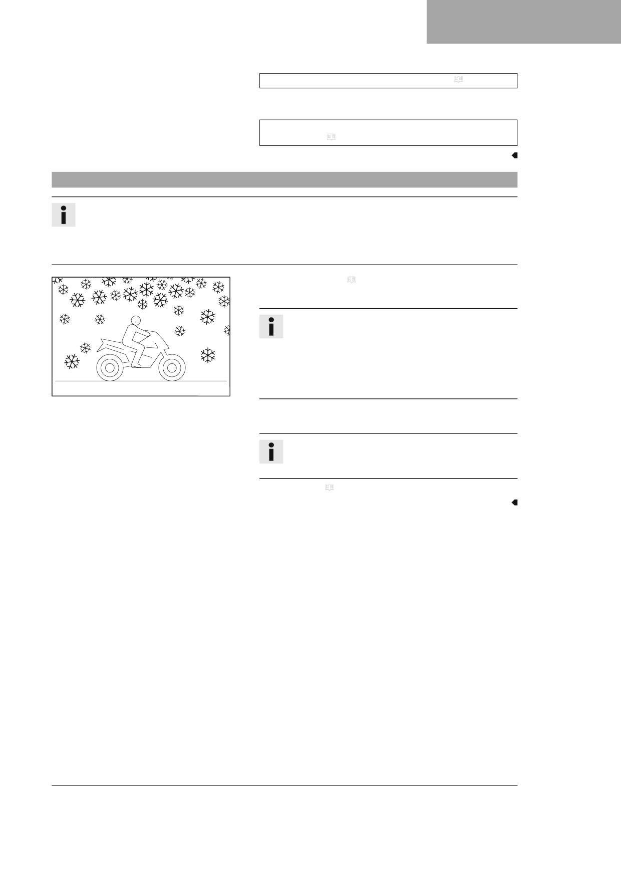
CLEANING, CARE
19
Preserving materials for paints, metal and rubber ( p. 144)
- Treat all plastic parts and powder-coated parts with a mild cleaning
and care product.
Special cleaner for glossy and matte paint finishes, metal and
plastic surfaces ( p. 145)
19.2
Checks and maintenance steps for winter operation
Info
If you use the vehicle in winter, you must expect salt on the roads. You should therefore take precautions against
aggressive road salt.
If the vehicle was operated in road salt, clean it with cold water after riding. Warm water would enhance the corro-
sive effects of salt.
- Clean the motorcycle. ( p. 126)
- Clean brake system.
Info
After EVERY trip on salted roads, thoroughly clean the brake
calipers and brake linings, after they have cooled down and
without removing them, with cold water and dry them care-
fully.
After riding on salted roads, thoroughly clean the vehicle
401060-01
with cold water and dry it well.
- Treat the engine, link fork, and all other bare or zinc-plated parts
(except the brake discs) with a wax-based corrosion inhibitor.
Info
Corrosion inhibitor must not come in contact with the brake
discs as this would greatly reduce the braking force.
- Clean the chain. ( p. 73)
127

20
STORAGE
20.1
Storage
Warning
Danger of poisoning Fuel is harmful to health.
- Avoid skin, eye and clothing contact with fuel.
- Immediately consult a doctor if you swallow fuel.
- Do not inhale fuel vapors.
- Rinse the affected area immediately with plenty of water in the event of contact with the skin.
- Rinse the eyes thoroughly with water, and consult a doctor in case of fuel contact with the eyes.
- Change your clothing if fuel spills on them.
- Keep fuels correctly in a suitable canister, and out of the reach of children.
Info
If you plan to garage the motorcycle for a longer period, perform the following steps or have them performed.
Before storing the motorcycle, check all parts for function and wear. If service, repairs, or replacements are neces-
sary, you should do this during the storage period (less workshop overload). In this way, you can avoid long work-
shop waiting times at the start of the new season.
- When refueling for the last time before taking the motorcycle out of
service, add fuel additive.
Fuel additive ( p. 144)
- Refuel. ( p. 38)
Tip
Fill the fuel tank completely as specified, using fuel with the
lowest possible ethanol content.
401058-01
- Clean the motorcycle. ( p. 126)
- Change the engine oil and oil filter, clean the oil screen.
(
p. 122)
– Check the antifreeze and coolant level. ( p. 111)
- Check the tire pressure. ( p. 99)
- Remove the 12-V battery.
(
p. 101)
– Charge the 12-V battery.
(
p. 102)
Guideline
Storage temperature of the
0 … 35 °C (32 … 95 °F)
12-V battery without direct
sunlight
- Store the vehicle in a dry location that is not subject to large fluctua-
tions in temperature.
Info
GASGAS Motorcycles recommends jacking up the motorcy-
cle.
- Raise the motorcycle with a lift stand. ( p. 50)
- Preferably cover the motorcycle with a tarp or similar cover that is
permeable to air. Do not use non-porous materials since they pre-
vent humidity from escaping, thus causing corrosion.
128

STORAGE
20
Info
Avoid running the engine for a short time only. Since the
engine cannot warm up properly, the water vapor produced
during combustion condenses and causes valves and the
exhaust system to rust.
20.2
Preparing for use after storage
- Remove the motorcycle from the lift stand. ( p. 50)
- Install the 12-V battery.
(
p. 102)
– Perform checks and maintenance measures when preparing for use.
(
p. 33)
– Take a test ride.
401059-01
129

21
TROUBLESHOOTING
Faults
Possible cause
Action
The engine cannot be cranked
Operating error
-
Carry out start procedure. ( p. 33)
(starter motor)
12-V battery discharged
-
Charge the 12-V battery.
(
p. 102)
–
Check the charging voltage.
–
Check the open-circuit current.
–
Check the stator winding of the alterna-
tor.
Main fuse blown
-
Change the main fuse. ( p. 104)
Starter relay defective
-
Check the starter relay.
Starter motor defective
-
Check the starter motor.
The engine turns but does not
Operating error
-
Carry out start procedure. ( p. 33)
start
Quick release coupling not joined
-
Join quick release coupling.
Fuse 1 blown
-
Change the fuses of individual electrical
power consumers.
Fuse 4 blown
-
Change the fuses of individual electrical
power consumers.
Idle speed is not set correctly
-
Adjust the idle speed.
(
p. 118)
Spark plug sooty or wet
-
Clean and dry the spark plug and spark
plug connector, or change if necessary.
Plug gap of spark plug too wide
-
Adjust plug gap.
Guideline
Spark plug electrode gap
1.0 mm (0.039 in)
Ignition system defective
-
Check the ignition system.
Short-circuit cable in wiring har-
-
Check the wiring harness. (visual check)
ness frayed, stop button or emer-
–
Check the electrical system.
gency OFF switch faulty
Error in the electronic fuel injec-
-
Read out the fault memory using the GAS-
tion
GAS Motorcycles diagnostics tool.
Engine does not speed up
Error in the electronic fuel injec-
-
Read out the fault memory using the GAS-
tion
GAS Motorcycles diagnostics tool.
Ignition system defective
-
Ignition coil - check the secondary wind-
ing.
-
Check the spark plug connector.
–
Check the stator winding of the alterna-
tor.
Engine has too little power
Air filter heavily contaminated
-
Clean the air filter and air filter box.
(
p. 65)
Fuel filter is very dirty
-
Change the fuel filter.
Fuel screen is very dirty
-
Change the fuel screen.
(
p. 121)
Error in the electronic fuel injec-
-
Read out the fault memory using the GAS-
tion
GAS Motorcycles diagnostics tool.
Exhaust system leaky, deformed
-
Check exhaust system for damage.
or too little glass fiber yarn filling
–
Change the glass fiber yarn filling in the
in the main silencer
main silencer.
(
p. 69)
Valve clearance too little
-
Adjust the valve clearance.
Ignition system defective
-
Ignition coil - check the secondary wind-
ing.
-
Check the spark plug connector.
–
Check the stator winding of the alterna-
tor.
130

TROUBLESHOOTING
21
Faults
Possible cause
Action
The engine dies during the trip
Lack of fuel
-
Refuel. ( p. 38)
Fuse 1 blown
-
Change the fuses of individual electrical
power consumers.
Fuse 4 blown
-
Change the fuses of individual electrical
power consumers.
Engine overheats
Coolant level low in cooling sys-
-
Check the cooling system for leaks.
tem
-
Check the coolant level. ( p. 112)
Insufficient airflow
-
Switch off engine when stationary.
Radiator fins very dirty
-
Clean radiator fins.
Foam formation in cooling system
-
Drain the coolant.
(
p. 112)
–
Refill the coolant.
(
p. 113)
Bent radiator hose
-
Change the radiator hose.
Thermostat defective
-
Check the thermostat.
Guideline
Opening temperature: 70 °C (158 °F)
Defect in radiator fan system
-
Check the radiator fan fuse.
–
Check fuse 4.
–
Check the radiator fan.
Malfunction indicator lamp lights
Error in the electronic fuel injec-
-
Check wiring for damage and electrical
up or flashes
tion
plug-in connectors for corrosion and dam-
age.
-
Read out the fault memory using the GAS-
GAS Motorcycles diagnostics tool.
High oil consumption
Engine vent hose bent
-
Route the vent hose without bends or
replace it if necessary.
Engine oil level too high
-
Check the engine oil level. ( p. 122)
Engine oil too thin (low viscosity)
-
Change the engine oil and oil filter, clean
the oil screen.
(
p. 122)
Piston and cylinder worn
-
Measure the piston/cylinder mounting
clearance.
12-V battery discharged
The 12-V battery is not being
-
Check the charging voltage.
charged by the alternator
-
Check the stator winding of the alterna-
tor.
Unwanted electrical power con-
-
Check the open-circuit current.
sumer
Values in combination instrument
The combination instrument bat-
-
Change combination instrument battery.
deleted (time, stop watch, lap
tery is empty
(
p. 109)
times)
The high beam, low beam, tail
Fuse 2 blown
-
Change the fuses of individual electrical
light, position light, and license
power consumers.
plate lamp are not working
The horn, brake light, turn signal,
Fuse 3 blown
-
Change the fuses of individual electrical
and radiator fan are not working
power consumers.
131

22
BLINK CODE
Info
The blink codes are only displayed by the derestricted version of the vehicle.
Blink code for malfunction
indicator lamp
02a Malfunction indicator lamp flashes 2x per second
Error level condition
Throttle valve position programming necessary
Blink code for malfunction
indicator lamp
02 Malfunction indicator lamp flashes 2x short
Error level condition
Crankshaft speed sensor - circuit fault
Blink code for malfunction
indicator lamp
06 Malfunction indicator lamp flashes 6x short
Error level condition
Throttle valve position sensor circuit A - input signal too low
Throttle valve position sensor circuit A - input signal too high
Blink code for malfunction
indicator lamp
09 Malfunction indicator lamp flashes 9x short
Error level condition
Induction manifold pressure sensor, cylinder 1 - input signal too low
Induction manifold pressure sensor cylinder 1 - input signal too high
Blink code for malfunction
indicator lamp
12 Malfunction indicator lamp flashes 1x long, 2x short
Error level condition
Coolant temperature sensor - input signal too low
Coolant temperature sensor - input signal too high
Blink code for malfunction
indicator lamp
13 Malfunction indicator lamp flashes 1x long, 3x short
Error level condition
Intake air temperature sensor - input signal too low
Intake air temperature sensor - input signal too high
Blink code for malfunction
indicator lamp
15 Malfunction indicator lamp flashes 1x long, 5x short
Error level condition
Tilt sensor - input signal too low
Tilt sensor - input signal too high
Blink code for malfunction
indicator lamp
21 Malfunction indicator lamp flashes 2x long, 1x short
Error level condition
Battery voltage - input voltage too high
132

BLINK CODE
22
Blink code for malfunction
indicator lamp
22 Malfunction indicator lamp flashes 2x long, 2x short
Error level condition
Gear position sensor - input voltage too high
Gear position sensor - input voltage too low
Blink code for malfunction
indicator lamp
33 Malfunction indicator lamp flashes 3x long, 3x short
Error level condition
Injector cylinder 1 - circuit fault
Blink code for malfunction
indicator lamp
37 Malfunction indicator lamp flashes 3x long, 7x short
Error level condition
Ignition coil 1, cylinder 1 - circuit fault
Blink code for malfunction
indicator lamp
41 Malfunction indicator lamp flashes 4x long, 1x short
Error level condition
Fuel pump relay - short circuit to ground or open circuit
Fuel pump controller - input signal too low
133

23
TECHNICAL SPECIFICATIONS
23.1
Engine
Design
1-cylinder 4-stroke engine, water-cooled
Displacement (All 450 models)
449.9 cm³ (27.455 cu in)
Displacement (All 500 models)
510.9 cm³ (31.177 cu in)
Stroke (All 450 models)
63.4 mm (2.496 in)
Stroke (All 500 models)
72 mm (2.83 in)
Bore
95 mm (3.74 in)
Compression ratio
12.75:1
Idle speed
1,800 … 1,900 rpm
Control
OHC, 4 valves controlled via rocker arm
Valve diameter, intake
40 mm (1.57 in)
Valve diameter, exhaust
33 mm (1.3 in)
Valve clearance
Intake at: 20 °C (68 °F)
0.10 … 0.15 mm (0.0039 … 0.0059 in)
Exhaust at: 20 °C (68 °F)
0.12 … 0.17 mm (0.0047 … 0.0067 in)
Crankshaft bearing
2 cylinder roller bearing
Conrod bearing
Slide bearing
Piston pin bearing
Bearing bush
Pistons
Forged light alloy
Piston rings
1 compression ring, 1 oil scraper ring
Engine lubrication
Pressure circulation lubrication with 2 trochoidal pumps
Primary transmission
29:72
Clutch
Multidisc clutch in oil bath, hydraulically activated
Gearbox
6-gear transmission, claw shifted
Transmission ratio
first-gear
13:33
second-gear
16:30
third-gear
18:26
fourth-gear
22:26
fifth-gear
23:23
sixth-gear
26:22
Alternator
14 V, 196 W
Ignition
Contactless controlled fully electronic ignition with digital
ignition adjustment
Spark plug
NGK LZMAR8BI - 10
Spark plug electrode gap
1.0 mm (0.039 in)
Cooling
Water cooling, permanent circulation of coolant by water
pump
Starting aid
Starter motor
134

TECHNICAL SPECIFICATIONS
23
23.2
Engine tightening torques
Screw, oil nozzle bent for piston cool-
M4
2 Nm (1.5 lbf ft)
ing
Loctite®243™
Oil nozzle for piston cooling
M5
2 Nm (1.5 lbf ft)
Loctite®243™
Screw, bearing retainer
M5
6 Nm (4.4 lbf ft)
Loctite®243™
Screw, clutch spring retainer
M5
8 Nm (5.9 lbf ft)
Screw, gear position sensor
M5x14
5 Nm (3.7 lbf ft)
Loctite®243™
Screw, locking lever
M5
6 Nm (4.4 lbf ft)
Loctite®243™
Screw, stator
M5
6 Nm (4.4 lbf ft)
Loctite®2701™
Fuel vapor retention system connec-
M6
5 Nm (3.7 lbf ft)
tion screw
Nut, water pump impeller
M6
6 Nm (4.4 lbf ft)
Loctite®243™
Screw, alternator cover
M6
10 Nm (7.4 lbf ft)
Screw, clutch cover
M6
10 Nm (7.4 lbf ft)
Screw, clutch slave cylinder
M6
10 Nm (7.4 lbf ft)
Screw, cylinder head
M6x75
10 Nm (7.4 lbf ft)
Screw, exhaust flange
M6x16
10 Nm (7.4 lbf ft)
Loctite®243™
Screw, fuel vapor retention system
M6
5 Nm (3.7 lbf ft)
lock
Loctite®243™
Screw, oil filter cover
M6x16
10 Nm (7.4 lbf ft)
Screw, shift drum locating unit
M6x30
10 Nm (7.4 lbf ft)
Loctite®243™
Screw, shift lever
M6x16
14 Nm (10.3 lbf ft)
Loctite®243™
Screw, starter motor
M6x25
10 Nm (7.4 lbf ft)
Screw, tensioning rail
M6
10 Nm (7.4 lbf ft)
Loctite®243™
Screw, timing chain clip
M6
10 Nm (7.4 lbf ft)
Loctite®243™
Screw, timing chain tensioner
M6
10 Nm (7.4 lbf ft)
Screw, valve cover
M6
10 Nm (7.4 lbf ft)
Crankshaft clamp screw plug
M8
10 Nm (7.4 lbf ft)
Crankshaft locking bolt
M8
10 Nm (7.4 lbf ft)
Screw, engine sprocket
M10
60 Nm (44.3 lbf ft)
Loctite®2701™
Screw, rotor
M10x1
70 Nm (51.6 lbf ft)
Spark plug
M10x1
10 … 12 Nm (7.4 … 8.9 lbf ft)
Engine coolant temperature sensor
M10x1.25
12 Nm (8.9 lbf ft)
135
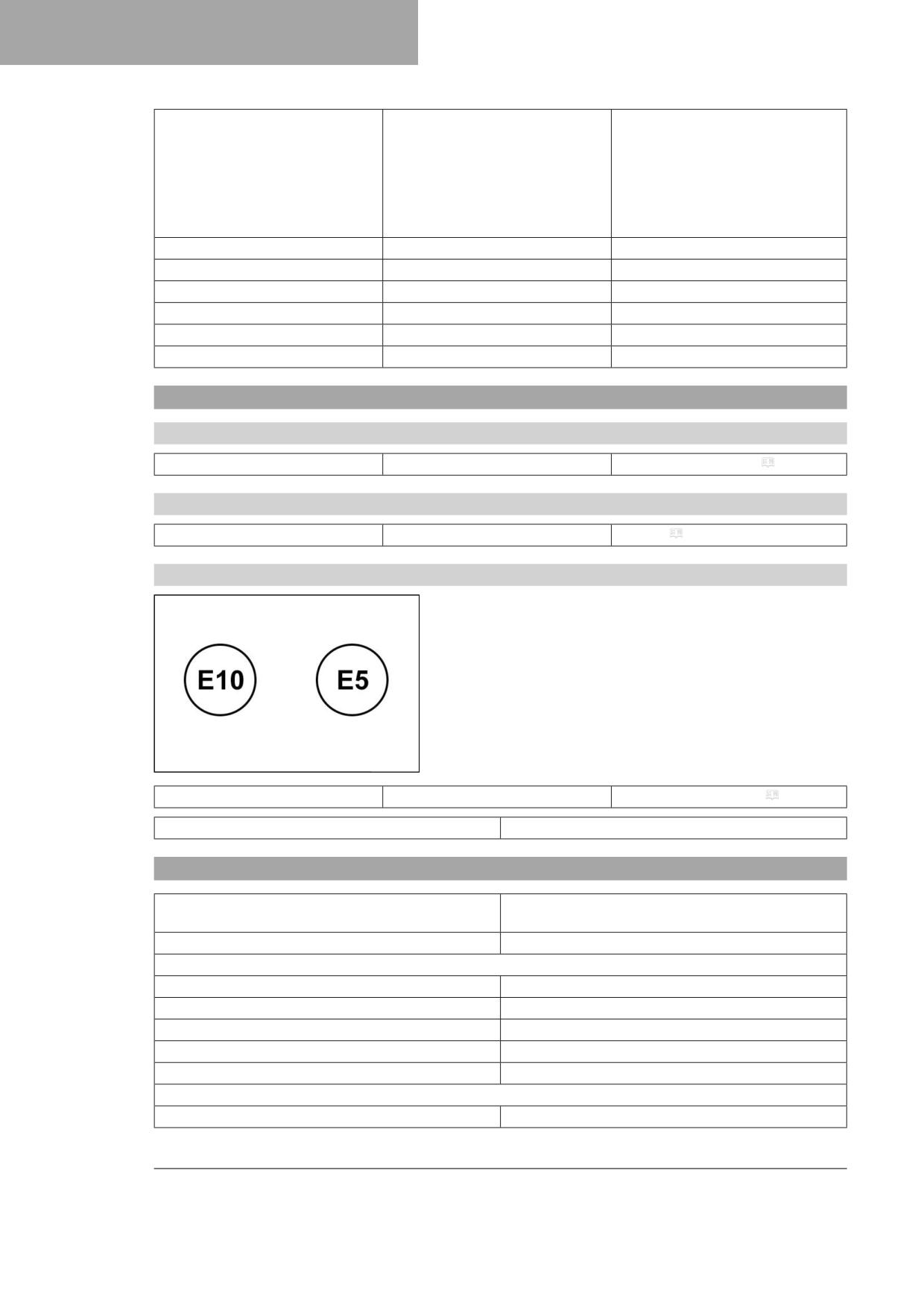
23
TECHNICAL SPECIFICATIONS
Screw, cylinder head
M10x1.25
1st stage
10 Nm (7.4 lbf ft)
2nd stage
30 Nm (22.1 lbf ft)
3rd stage
50 Nm (36.9 lbf ft)
Collar and thread oiled
Oil drain plug with magnet
M12x1.5
20 Nm (14.8 lbf ft)
Screw plug, oil pressure control valve
M12x1.5
20 Nm (14.8 lbf ft)
Nut, inner clutch hub
M18x1.5
100 Nm (73.8 lbf ft)
Nut, primary gear wheel
M18LHx1.5
120 Nm (88.5 lbf ft)
Screw plug, oil screen
M20x1.5
15 Nm (11.1 lbf ft)
Screw plug, alternator cover
M24x1.5
18 Nm (13.3 lbf ft)
23.3
Capacities
23.3.1
Engine oil
Engine oil
1.2 l (1.3 qt.)
Engine oil (SAE 10W/50) ( p. 142)
23.3.2
Coolant
Coolant
0.95 l (1 qt.)
Coolant ( p. 142)
23.3.3
Fuel
Please observe the labels on EU fuel pumps.
A00420-10
Total fuel tank capacity, approx.
8.5 l (2.25 US gal)
Super unleaded (ROZ 95) ( p. 143)
Fuel reserve, approx.
1.5 l (1.6 qt.)
23.4
Chassis
Frame
Central tube frame made of chrome molybdenum steel
tubing
Fork
WPXPLOR OC
Suspension travel
front
300 mm (11.81 in)
rear
310 mm (12.2 in)
Fork offset
22 mm (0.87 in)
Shock absorber
WP XPLOR LDS
Brake system
Disc brakes, floating brake calipers
Brake discs - diameter
front
260 mm (10.24 in)
136

TECHNICAL SPECIFICATIONS
23
rear
220 mm (8.66 in)
Brake discs - wear limit
front
2.5 mm (0.098 in)
rear
3.5 mm (0.138 in)
Offroad tire pressure
front
1.0 bar (15 psi)
rear
1.0 bar (15 psi)
Street tire pressure
front
2.0 bar (29 psi)
rear
2.0 bar (29 psi)
Final drive (EC 450F EU)
14:52 (13:52)
Final drive (EC 500F EU)
14:50 (13:50)
Final drive (EW 500F US)
14:48
Final drive (EC 450F US)
13:52
Chain
5/8 x 1/4"
Rear sprockets available
48, 49, 50, 51, 52
Steering head angle
63.9°
Wheelbase
1,488 ± 10 mm (58.58 ± 0.39 in)
Seat height unloaded
963 mm (37.91 in)
Ground clearance unloaded
347 mm (13.66 in)
Weight without fuel, approx. (EW 500F US)
110.6 kg (243.8 lb.)
Weight without fuel, approx. (All 450 models)
107.4 kg (236.8 lb.)
Weight without fuel, approx. (All 500 models)
109 kg (240 lb.)
Maximum permissible front axle load
145 kg (320 lb.)
Maximum permissible rear axle load
190 kg (419 lb.)
Maximum permissible overall weight
335 kg (739 lb.)
23.5
Electrical system
12-V battery
HJTZ5S-FP-C
Lithium-ion battery
Battery voltage: 12 V
Nominal capacity: 2.0 Ah
Maintenance-free
Combination instrument battery
CR 2430
Battery voltage: 3 V
Fuse
58011109120
20 A
Headlight
LED
Parking light
LED
Indicator lamps
W2.3W / socket W2x4.6d
12 V
2.3 W
Turn signal
R10W / socket BA15s
12 V
10 W
Brake/tail light
LED
License plate lamp
LED
137

23
TECHNICAL SPECIFICATIONS
23.6
Tires
Validity
Front tire
Rear tire
(All EU models)
90/90 - 21 M/C 54R M+S TT
140/80 - 18 M/C 70R TT
MAXXIS Maxx Enduro
MAXXIS Maxx Enduro
(All US models)
80/100 - 21 51M TT
110/100 - 18 64M TT
Dunlop GEOMAX MX33F
Dunlop GEOMAX AT81
The tires specified represent one of the possible series production tires. For alternative manufacturers, if any, contact an
authorized dealer or qualified tire dealership. If local road approval regulations apply, these and the respective technical
specifications must be observed. Additional information is available in the Service section under:
23.7
Fork
Fork article number
A590C169X401000
Fork
WPXPLOR OC
Compression damping
Comfort
18 clicks
Standard
15 clicks
Sport
12 clicks
Rebound damping
Comfort
18 clicks
Standard
15 clicks
Sport
12 clicks
Spring length with preload spacer(s)
474 mm (18.66 in)
Spring rate
Weight of rider: 65 … 75 kg (143 … 165 lb.)
4.6 N/mm (26.3 lb/in)
Weight of rider: 75 … 85 kg (165 … 187 lb.)
4.8 N/mm (27.4 lb/in)
Weight of rider: 85 … 95 kg (187 … 209 lb.)
5.0 N/mm (28.6 lb/in)
Fork length
940 mm (37.01 in)
Fork oil per fork leg
635 ± 10 ml (21.47 ± 0.34 fl. oz.)
Fork oil (SAE 4) (48601166S1)
(
p. 142)
23.8
Shock absorber
Shock absorber article number
A390C467X408000
Shock absorber
WP XPLOR LDS
Lowspeed compression damping
Comfort
18 clicks
Standard
15 clicks
Sport
12 clicks
Highspeed compression damping
Comfort
2.5 turns
Standard
2 turns
Sport
1.5 turns
Rebound damping
Comfort
18 clicks
Standard
15 clicks
Sport
12 clicks
138

TECHNICAL SPECIFICATIONS
23
Spring preload
7 mm (0.28 in)
Spring rate
Weight of rider: 65 … 75 kg (143 … 165 lb.)
42 N/mm (240 lb/in)
Weight of rider: 75 … 85 kg (165 … 187 lb.)
45 N/mm (257 lb/in)
Weight of rider: 85 … 95 kg (187 … 209 lb.)
48 N/mm (274 lb/in)
Spring length
240 mm (9.45 in)
Gas pressure
10 bar (145 psi)
Static sag
40 mm (1.57 in)
Riding sag
110 mm (4.33 in)
Fitted length
456.3 mm (17.965 in)
Shock absorber oil
Shock absorber fluid (SAE 2.5)
(50180751S1) ( p. 143)
23.9
Chassis tightening torques
Fuel connection on the fuel pump
EJOT PT® K60x30-Z
2.5 Nm (1.84 lbf ft)
Hose clamp, radiator
-
2.4 Nm (1.77 lbf ft)
Hose connector, active carbon filter
-
3.8 Nm (2.8 lbf ft)
Remaining screws, chassis
EJOT PT® K60x25-Z
2 Nm (1.5 lbf ft)
Screw for spoiler attachment
EJOT PT® K60x23/18
2.5 Nm (1.84 lbf ft)
Screw, front seat fixing
EJOT PT® K60x23/18
2.5 Nm (1.84 lbf ft)
Screw, intake air temperature sensor
EJOT PT® K50x18
0.7 Nm (0.52 lbf ft)
Start-stop switch screw
EJOT PT® K50x18 T20
2 Nm (1.5 lbf ft)
Fitting, inlet sleeve to throttle valve
M4
2.8 Nm (2.07 lbf ft)
body
Screw, fixed grip
M4
5 Nm (3.7 lbf ft)
Loctite®243™
Spoke nipple, front wheel
M4.5
6 Nm (4.4 lbf ft)
Spoke nipple, rear wheel
M4.5
6 Nm (4.4 lbf ft)
Remaining nuts, chassis
M5
5 Nm (3.7 lbf ft)
Remaining screws, chassis
M5
5 Nm (3.7 lbf ft)
Screw, battery terminal
M5
2.5 Nm (1.84 lbf ft)
Screw, frame protector
M5
3 Nm (2.2 lbf ft)
Screw, light switch
M5
1 Nm (0.7 lbf ft)
Screw, shock absorber adjusting ring
M5
5 Nm (3.7 lbf ft)
Screw, spoiler on fuel tank (All EC
M5x12
1.5 Nm (1.11 lbf ft)
models)
Screw, throttle valve body cover
M5
2.6 Nm (1.92 lbf ft)
Screw, turn signal switch
M5
1 Nm (0.7 lbf ft)
Nut, starter motor
M6
4 Nm (3 lbf ft)
Nut, throttle cable on throttle valve
M6
3 Nm (2.2 lbf ft)
body
Remaining nuts, chassis
M6
10 Nm (7.4 lbf ft)
Remaining screws, chassis
M6
10 Nm (7.4 lbf ft)
Screw, ball joint of push rod on rear
M6
10 Nm (7.4 lbf ft)
brake cylinder
Loctite®243™
Screw, battery support bracket
M6
6 Nm (4.4 lbf ft)
Screw, brake lever
M6
5 Nm (3.7 lbf ft)
139
23
TECHNICAL SPECIFICATIONS
Screw, brake line guide on link fork
M6
4.5 Nm (3.32 lbf ft)
Screw, cable on starter relay
M6
6 Nm (4.4 lbf ft)
Screw, chain guide on link fork at the
M6
10 Nm (7.4 lbf ft)
front
Screw, chain guide on link fork at the
M6
10 Nm (7.4 lbf ft)
rear
Loctite®243™
Screw, chain sliding guard
M6
6 Nm (4.4 lbf ft)
Loctite®243™
Screw, clutch lever
M6
5 Nm (3.7 lbf ft)
Screw, connector board with combi-
M6
5 Nm (3.7 lbf ft)
nation instrument
Screw, fender
M6
12 Nm (8.9 lbf ft)
Screw, front brake disc
M6
14 Nm (10.3 lbf ft)
Loctite®243™
Screw, fuel tank spoiler on radiator
M6
6 Nm (4.4 lbf ft)
Screw, rear brake disc
M6
14 Nm (10.3 lbf ft)
Loctite®243™
Screw, throttle grip
M6
5 Nm (3.7 lbf ft)
Nut, rear sprocket screw
M8
35 Nm (25.8 lbf ft)
Loctite®2701™
Nut, rim lock
M8
12 Nm (8.9 lbf ft)
Rear brake lever stop nut
M8
20 Nm (14.8 lbf ft)
Remaining nuts, chassis
M8
25 Nm (18.4 lbf ft)
Remaining screws, chassis
M8
25 Nm (18.4 lbf ft)
Screw, bottom triple clamp
M8
15 Nm (11.1 lbf ft)
Screw, chain sliding piece
M8
15 Nm (11.1 lbf ft)
Screw, engine brace on engine
M8x20
25 Nm (18.4 lbf ft)
Loctite®243™
Screw, engine brace on frame
M8x15
25 Nm (18.4 lbf ft)
Loctite®2701™
Screw, engine sprocket cover
M8
15 Nm (11.1 lbf ft)
Screw, fork stub
M8
15 Nm (11.1 lbf ft)
Screw, front brake caliper
M8
25 Nm (18.4 lbf ft)
Loctite®243™
Screw, handlebar clamp
M8
20 Nm (14.8 lbf ft)
Screw, manifold on cylinder head
M8
15 Nm (11.1 lbf ft)
brace
Screw, side stand attachment
M8
33 Nm (24.3 lbf ft)
Loctite®2701™
Screw, subframe, bottom
M8
30 Nm (22.1 lbf ft)
Loctite®2701™
Screw, top steering stem
M8
20 Nm (14.8 lbf ft)
Loctite®243™
Screw, top triple clamp
M8
20 Nm (14.8 lbf ft)
Screw, wheel speed sensor on axle
M8
4.5 Nm (3.32 lbf ft)
clamp
Top subframe screw
M8
35 Nm (25.8 lbf ft)
Loctite®2701™
Engine attachment bolt
M10
60 Nm (44.3 lbf ft)
Remaining nuts, chassis
M10
45 Nm (33.2 lbf ft)
140

TECHNICAL SPECIFICATIONS
23
Remaining screws, chassis
M10
45 Nm (33.2 lbf ft)
Screw, handlebar holder
M10
40 Nm (29.5 lbf ft)
Loctite®243™
Screw, bottom shock absorber
M12
80 Nm (59 lbf ft)
Loctite®2701™
Screw, top shock absorber
M12
80 Nm (59 lbf ft)
Loctite®2701™
Nut, angle lever to link fork
M16x1.5
80 Nm (59 lbf ft)
Nut, fork pivot
M16x1.5
100 Nm (73.8 lbf ft)
Nut, linkage lever on angle lever
M16x1.5
80 Nm (59 lbf ft)
Screw, front wheel spindle
M20x1.5
35 Nm (25.8 lbf ft)
Screw, top steering head
M20x1.5
12 Nm (8.9 lbf ft)
Nut, wheel spindle, rear
M22x1.5
80 Nm (59 lbf ft)
Screw-in fitting, cooling system
M24x1.5
7.5 Nm (5.53 lbf ft)
141

24
SUBSTANCES
Brake fluid DOT 4 / DOT 5.1
Standard/classification
- DOT
Guideline
- Use only brake fluid that complies with the specified standard (see specifications on the container) and that exhibits the
corresponding properties.
Recommended supplier
Castrol
- REACT PERFORMANCE DOT 4
MOTOREX®
- Brake Fluid DOT 5.1
Coolant
Guideline
- Only use high-grade, silicate-free coolant with corrosion inhibitor additive for aluminum motors. Low grade and unsuit-
able antifreeze causes corrosion, deposits and frothing.
- Do not use pure water as only coolant is able to meet the requirements needed in terms of corrosion protection and
lubrication properties.
- Only use coolant that complies with the requirements stated (see specifications on the container) and that has the rele-
vant properties.
Antifreeze protection to at least
-25 °C (-13 °F)
The mixture ratio must be adjusted to the necessary antifreeze protection. Use distilled water if the coolant needs to be
diluted.
The use of premixed coolant is recommended.
Observe the coolant manufacturer specifications for antifreeze protection, dilution and miscibility (compatibility) with other
coolants.
Recommended supplier
MOTOREX®
- COOLANT M3.0
Engine oil (SAE 10W/50)
Standard/classification
- JASO T903 MA2 ( p. 146)
- SAE ( p. 146) (SAE 10W/50)
Guideline
- Use only engine oils that comply with the specified standards (see specifications on the container) and that possess the
corresponding properties.
Fully synthetic engine oil
Recommended supplier
MOTOREX®
- Cross Power 4T
Fork oil (SAE 4) (48601166S1)
Standard/classification
- SAE ( p. 146) (SAE 4)
Guideline
- Use only oils that comply with the specified standards (see specifications on the container) and that exhibit the corre-
sponding properties.
142

SUBSTANCES
24
Shock absorber fluid (SAE 2.5) (50180751S1)
Standard/classification
- SAE ( p. 146) (SAE 2.5)
Guideline
- Use only oils that comply with the specified standards (see specifications on the container) and that exhibit the corre-
sponding properties.
Super unleaded (ROZ 95)
Standard/classification
- DIN EN 228 (ROZ 95)
Guideline
- Only use super unleaded fuel that matches or is equivalent to the specified standard.
- Fuel with an ethanol content of up to 10% (E10 fuel) is safe to use.
Info
Do not use fuel containing methanol (e.g., M15, M85, M100) or more than 10% ethanol (e.g., E15, E25, E85,
E100).
143

25
AUXILIARY SUBSTANCES
Air filter cleaner
Recommended supplier
MOTOREX®
- Racing Bio Dirt Remover
Chain cleaner
Recommended supplier
MOTOREX®
- Chain Clean
Fuel additive
Recommended supplier
MOTOREX®
- Fuel Stabilizer
High viscosity grease
Recommended supplier
SKF®
- LGHB 2
Long-life grease
Recommended supplier
MOTOREX®
- Bike Grease 2000
Motorcycle cleaner
Recommended supplier
MOTOREX®
- Moto Clean
Off-road chain spray
Recommended supplier
MOTOREX®
- Chainlube Offroad
Oil for foam air filter
Recommended supplier
MOTOREX®
- Racing Bio Liquid Power
Preserving materials for paints, metal and rubber
Recommended supplier
MOTOREX®
- Moto Protect
Silicone spray
Recommended supplier
MOTOREX®
- Silicone Spray
144

AUXILIARY SUBSTANCES
25
Special cleaner for glossy and matte paint finishes, metal and plastic surfaces
Recommended supplier
MOTOREX®
- Quick Cleaner
Universal oil spray
Recommended supplier
MOTOREX®
- Joker 440 Synthetic
145

26
STANDARDS
JASO T903 MA2
Different technical development directions required a separate specification for motorcycles - the JASO T903 MA2 stan-
dard.
Earlier, engine oils from the automobile industry were used for motorcycles because there was no separate motorcycle
specification.
Whereas long service intervals are demanded for automobile engines, the focus for motorcycle engines is on high perfor-
mance at high engine speeds.
In most motorcycle engines, the transmission and clutch are lubricated with the same oil.
The JASO T903 MA2 standard meets these special requirements.
SAE
The SAE viscosity classes were defined by the Society of Automotive Engineers and are used for classifying oils according to
their viscosity. The viscosity describes only one property of oil and says nothing about quality.
146

INDEX OF SPECIAL TERMS
27
OBD
On-board diagnosis
Vehicle system, which monitors the specified parameters
of the vehicle electronics
-
Quickshifter
Function of the engine electronics for shifting up without
clutch actuation
147

28
LIST OF ABBREVIATIONS
Art. no.
Article number
ca.
circa
cf.
compare
e.g.
for example
etc.
et cetera
i.a.
inter alia
no.
number
poss.
possibly
148

LIST OF SYMBOLS
29
29.1
Yellow and orange symbols
Yellow and orange symbols indicate an error condition that requires prompt intervention. Active driving aids are also repre-
sented by yellow or orange symbols.
Malfunction indicator lamp lights up/flashes yellow - The OBD has detected an error in the vehicle
electronics. Come safely to a halt, and contact an authorized GASGAS Motorcycles dealer.
The fuel level warning lamp lights up yellow - The fuel level has reached the reserve mark.
The fuel level warning lamp lights up yellow - The fuel level has reached the reserve mark.
29.2
Green and blue symbols
Green and blue symbols reflect information.
The high beam indicator lamp lights up blue - The high beam is switched on.
Turn signal indicator lamp flashes green - The turn signal is switched on.
The high beam indicator lamp lights up blue - The high beam is switched on.
149

INDEX
INDEX
cleaning
73
1
Chain guide
12-V battery
checking
75
charging
102
Chain tension
starting power
29
adjusting
74
12-V battery
checking
74
installing
102
Characteristic map of the throttle response
removing
101
adjusting
116
A
Clutch
Accessories
10
fluid level, checking/correcting
81
fluid, changing
82
Air filter
cleaning
65
Clutch lever
15
installing
65
basic position, adjusting
80
removing
64
Cold start button
19
Air filter box
Combination instrument
cleaning
65
adjusting
23
Air filter box cover
clock, setting
25
installing
64
combination instrument battery, changing
109
preparing for securing
66
kilometers or miles, setting
24
removing
63
message
23
overview
23
Antifreeze
service display, setting
25
checking
111
Compression damping
Auxiliary substances
10
fork, adjusting
47
B
Coolant
Basic chassis setting
antifreeze and coolant level, checking
111
rider's weight, checking with
42
changing
114
Blink code
132-133
draining
112
level, checking
112
Brake discs
refilling
113
checking
84
Cooling system
111
Brake fluid
Customer service
10
front brake, adding
85
rear brake, adding
91
D
Brake fluid level
Defined use
6
of front brake, checking
84
Diagnostics connector
110
of rear brake, checking
90
Difficult operating conditions
30
Brake lining retainers
dry sand
30
of front brake, checking
86
high temperatures
32
of rear brake, checking
92
low temperature
32
muddy surfaces
31
Brake linings
slow speed
32
of front brake, changing
87
snow
32
of front brake, checking
86
wet sand
31
of rear brake, checking
92
wet surfaces
31
of the rear brake, changing
92
E
Brake system
84-94
Engine
C
running in
29
Capacity
Engine number
14
coolant
113-114, 136
engine oil
124, 136
Engine oil
fuel
39, 136
adding
125
changing
122
Chain
checking
75
150

INDEX
Engine oil level
Headlight mask with headlight
checking
122
installing
106
removing
105
Engine sprocket
checking
75
Headlight setting
checking
107
Environment
8
High-speed compression damping
F
shock absorber, adjusting
43
Figures
10
Horn button
15
Foot brake lever
21
basic position, adjusting
89
I
free travel, checking
89
Idle speed
Fork legs
adjusting
118
basic setting, checking
47
Idle speed adjusting screw
20
bleeding
50
Implied warranty
10
dust boots, cleaning
51
Indicator lamps overview
18
installing
53
Intended use
6
removing
52
K
Fork protector
Key number
14
installing
52
removing
51
L
Frame
Light switch
16
checking
78
Link fork
Frame protector
checking
78
installing
54
Lower triple clamp
removing
53
installing
55
Front fender
removing
54
installing
59
Low-speed compression damping
removing
58
shock absorber, adjusting
42
Front wheel
M
installing
96
Main fuse
removing
95
changing
104
Fuel screen
Main silencer
changing
121
clean spark arrestor
67
Fuel tank
glass fiber yarn filling, changing
69
installing
71
installing
67
removing
70
removing
66
Fuel tank filler cap
Manufacturer warranty
10
closing
19
Mapping
opening
18
change (optional)
117
Fuel, oils, etc
10
Misuse
6
Fuse
Motorcycle
main fuse, changing
104
cleaning
126
H
lift stand, removing from
50
Hand brake lever
15
with lift stand, raising
50
basic position, adjusting
84
O
Handlebar position
48
OCU
110
adjusting
49
Oil filter
Headlight
changing
122
headlight range, adjusting
108
Oil screen
Headlight bulb
cleaning
122
changing
107
Overview of indicator lamps
17
Owner's Manual
9
151

INDEX
P
Starting
33
Starting power of lithium-ion batteries
at
low
Play in throttle cable
temperatures
29
adjusting
115
Steering
checking
115
locking
22
Preparing for use
unlocking
22
advice on preparing for first use
28
Steering head bearing
after storage
129
lubricating
58
checks and maintenance measures when preparing
for use
33
Steering head bearing play
adjusting
57
Protective clothing
8
checking
57
Q
Stop button
17
Quickshifter
Storage
128-129
activating (optional)
35
T
programming (optional)
80
Quickshifter (optional)
35
Technical specifications
capacities
136
R
chassis
136
Rear sprocket
chassis tightening torques
. . . 139
checking
75
electrical system
137
engine
134
Rear wheel
engine tightening torques
. . . 135
installing
97
fork
138
removing
96
shock absorber
138
Rebound damping
tires
138
fork, adjusting
48
Throttle cable routing
shock absorber, adjusting
43
checking
78
Refueling
Throttle grip
15
Fuel
38
Riding sag
Throttle valve position
programming
119
adjusting
46
Tire condition
Rubber grip
checking
99
checking
79
Tire pressure
S
checking
99
Safe operation
7
Traction control
Seat
activating (optional)
34
mounting
62
Transporting
37
removing
62
Troubleshooting
130-131
Service
10
Turn signal bulb
Service schedule
40-41
changing
108
Shift lever
20
Turn signal switch
16
basic position, adjusting
120
Type label
13
basic position, checking
119
Shock absorber
V
checking the rider sag
45
Vehicle identification number
13
installing
60
View of vehicle
removing
59
front left
11
spring preload, adjusting
45
rear right
12
static sag, checking
44
W
Side stand
21
Spare parts
10
Winter operation
checks and maintenance steps
. . . 127
Spoke tension
checking
100
Work rules
8
Start button
16
152