CNC boring machine. Manual (ver 20.09.19)
CNC boring machine manual ver20.09.19
This operation manual describes in detail the installation and use of the six-sided boring
machine, precautions and maintenance, common failure analysis, and simple processing
skills. Please read this manual carefully before operation. If you have any questions, please
contact the local dealer to solve them. Do not use the disassembly equipment without
authorization. Please keep this manual for a long time for future maintenance and repairs.
Contents
1.Machine placement and installation
-1-
1.1 Machine placement
-1-
1.2 Machine installation
-2-
2.Introduction to HIWCAM
-3-
2.1 HIWCAM interface layout
-3-
2.2 HIWCAM function overview
-4-
3.Actual processing
-4-
3.1 Processing files
-4-
3.2 Edit
-8-
3.3 DXF import
- 23 -
3.4 View
- 30 -
3.5 CNC operation
- 32 -
4.Manual
- 33 -
4.1 Peripheral operation
- 33 -
4.2 IO Input
- 35 -
4.3 IO Output
- 35 -
4.4 AXS information
- 36 -
5.parameter
- 38 -
5.1 Operation authority
- 39 -
5.2 Save parameters
- 39 -
5.3 Tool settings
- 39 -
5.4 Pressure plate parameters
- 40 -
5.5 General parameters
- 41 -
5.6 Advanced settings
- 43 -
5.7 Credit Investigation Authorization
- 44 -
5.8 Machine parameters
- 44 -
5.9 HMI
- 46 -
5.10 Pitch compensation
- 48 -
5.11 Absolute value
- 49 -
5.12 Alarm information
- 49 -
5.13 PLC programming
- 51 -
5.14 Clear data
- 52 -
5.15 Clear NC
- 53 -
Attachment 1: Instructions for updating six-sided boring machine CAM
- 54 -
Appendix 2: Servo alarm code
- 57 -
List of alarm codes
- 57 -
Alarm reason and treatment measures
- 61 -
2
1.Machine placement and installation
1.1 Machine placement
The machine is placed as shown in the figure below, and a leveling pad is placed under each
foot to adjust the machine level.
Placement diagram
The through-type hexahedral drill is divided into two parts: the front-end machine, the
back-end blanking platform, and the blanking platform is placed at the rear end of the hexahedral
drill. The placement is as shown in the figure. Adjust the height of the cutting platform, the height of
the cutting platform is the same as the height of the six-sided drilling platform or about 5mm lower
than the six-sided drilling platform.After the adjustment is completed, the placement of the
machine is completed.
-1-
1.2 Machine installation
After the machine is placed, turn on the power of the machine, and the machine is connected
to the back of the machine. The wiring method is shown in the figure below. L1, L2, and L3 are live
wires, and N is the neutral wire. Be sure to pay attention to the live wire when wiring, and the
neutral wire cannot be reversed.
The wiring method of the unloading platform is to connect the wires of the unloading platform
to the small chassis in the six-sided drill green PVC . The wire numbers are connected according
to the wire numbers on the wiring terminals in the above figure. On the two air pipes in the
chassis. After connecting, the unloading platform wiring is completed.
Pneumatic connection: After the line is connected, connect the gas path. The gas path is on
the other side of the terminal. The gas pipe uses a 10mm or 12mm diameter pipe. The air pressure
requires more than 6 stable air pressure. The connection method uses pneumatic fast Connector
connection.
-2-
2.Introduction to HIWCAM
2.1 HIWCAM interface layout
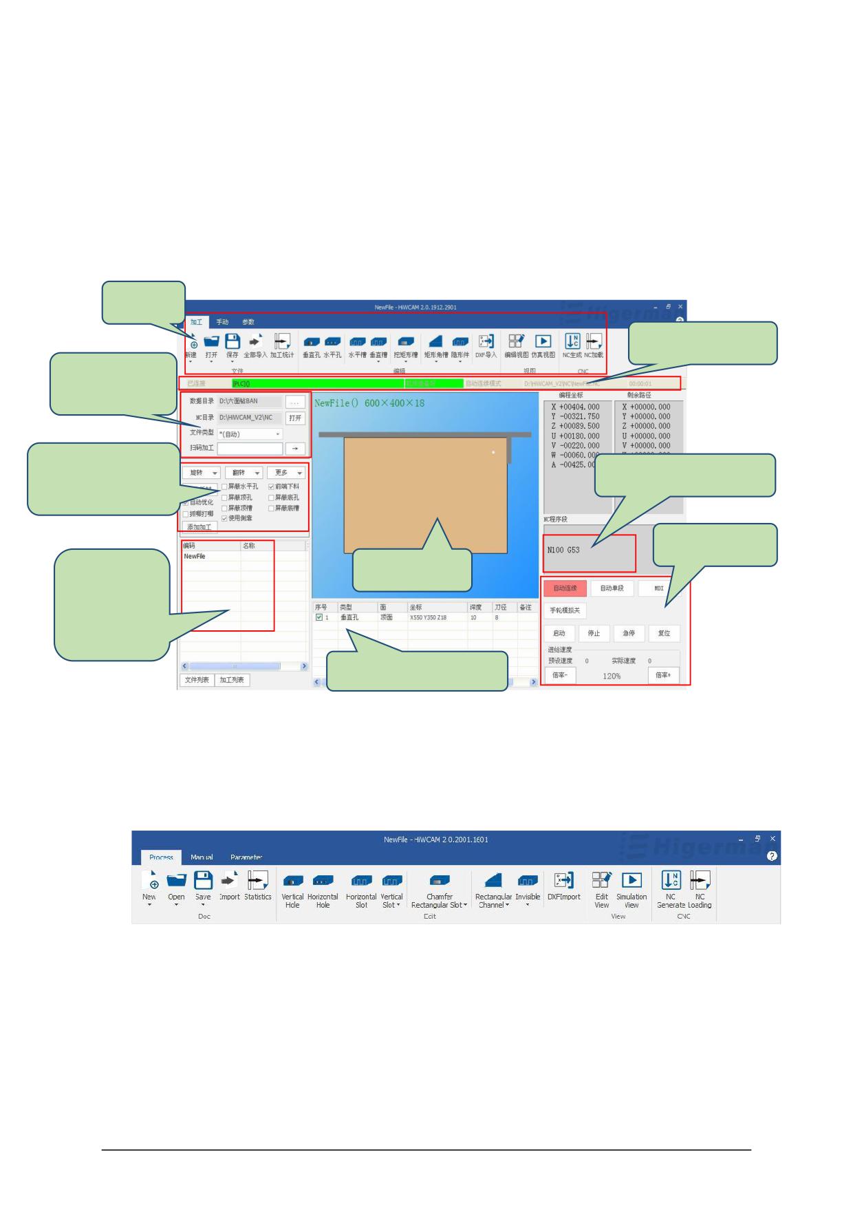
HIWCAM Basic interface layout as the FIG.
Menu
CNC status display
Nesting data
operation area
Plate optimization
CNC process program
ribbon
CNC operate
Display area
Disassembly
order data
import list
Processing item list area
The main interface of HIWCAM is divided into the following areas:
● Menu bar: Located at the top left of the interface, it mainly provides CAM tools classified
and used, including processing, manual, and parameters;
● Operation area for splitting data: import the splitting data directory; NC directory; file type;
scanning code processing ;
● Plate optimization function area: used for plate processing optimization and processing
function selection;
● Split data import list: display the actual processed plate information;
-3-
● Display area: display the size information of the plate, and the graph shows the actual
processing style of the plate;
● Processing list area: display the actual processing primitives of the plate, and edit the
primitives;
● CNC operating area: CNC mode can be selected, processing speed can be adjusted;
● CNC status bar: It can display the status of CNC.
2.2 HIWCAM function overview
◆ HIWCAM supports five-sided drilling processing center, six-sided drilling processing center,
six-sided drilling double-drilling package processing center, six-sided drilling connection
processing center, etc. for panel furniture.
◆ According to different types of machine tools, the software data of order splitting is
automatically recognized and processing is automatically completed.
◆ CAM software supports importing and dismantling software hole position data to
automatically convert into processing items, and also supports manual creation and editing of
drilling, grooving, grooving, milling, invisible parts and other processing items.
◆ Graphic display of the size of the plate and the position and size of each processing item.
◆ Support
the
data
docking
of
commonly
used
dismantling
software
( MPR , XML , BAN , BD , PDX , FMC, etc.).
◆ Support for re-editing, adding and deleting the processing items in the imported data.
◆ Automatically check the interference of the tool / gripper / fixture, and intelligently optimize
the fixture action, that is, the gripper hand change action.
◆ Automatic tool path optimization, reduce idle stroke, submit processing efficiency.
◆ Provide different processing schemes according to different hole and groove
characteristics.
◆ Provide graphical processing simulation function, according to the final processing
program to simulate the action logic of the drill, fixture and gripper.
3.Actual processing
3.1 Processing files
-4-
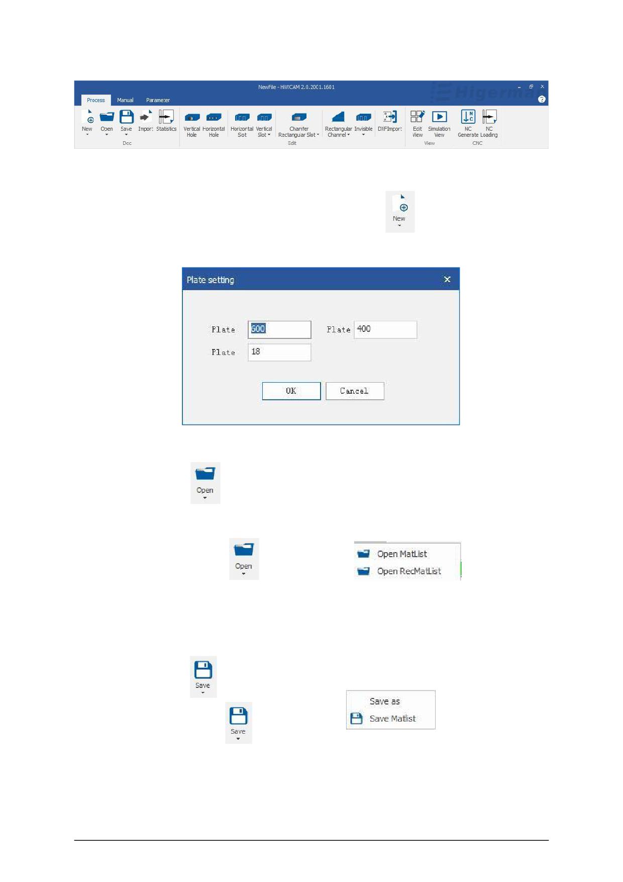
1. New processing file
In the status bar, select New under the processing function
, set the length, width, and
thickness of the plate in the pop-up dialog box, and click OK.
2.Open processing file
①Click the button
to pop up the file loading dialog box, you can manually find the file
from the disk and load it for processing.
②You can click the button
drop-down menu
to choose to open
the material list or open the recent material list. The open recent material list is the state of the
processing list automatically saved by the system before closing the software.
3.save
① Click the button
to save the current editing file.
②Click the button
drop-down menu
, you can save as, and
save the material list to save th
us information of the current processing list.
4.Batch Import
-5-
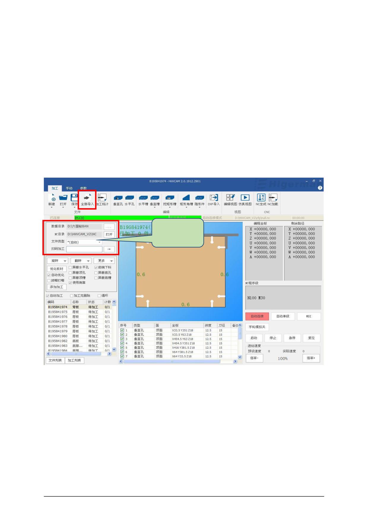
①Select the path and file type of the data directory in the data operation area of
the order
dismantling (dismantling software data format).
②Click the "import all" icon as shown in the figure below, the files under this path will be
added to the list of split data import, which can be viewed by clicking the mouse and scrolling the
wheel, and the information of the plate will be displayed in the display area.
③Scan code processing: "Scan code processing" mode. After scanning the code, the file is
directly added to the CNC system.
After that, press the "Start" or "Foot Switch" button to start automatic processing.
④ Plate optimization function area: used for plate processing optimization and processing
function
selection,
which
can
be
selected
and
used
according
to
actual
conditions.
Nesting data
operation area
-6-
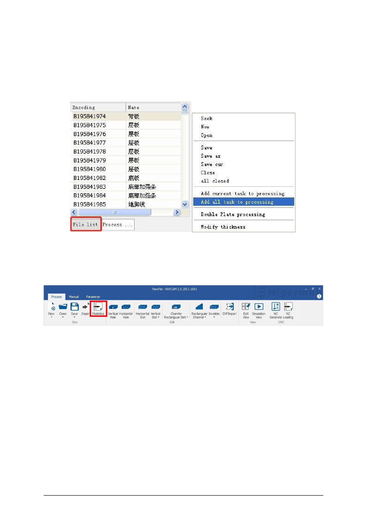
⑤ In the file list in the split order data import list, select a file and right-click it to search, create,
and open.
Save, save as, save as current, close, close all, add current to processing, add all to
processing, bilateral processing, modify plate thickness and other operations, as shown in the
figure below.
(For automatic machining, refer to section 2.5 CNC machining operations)
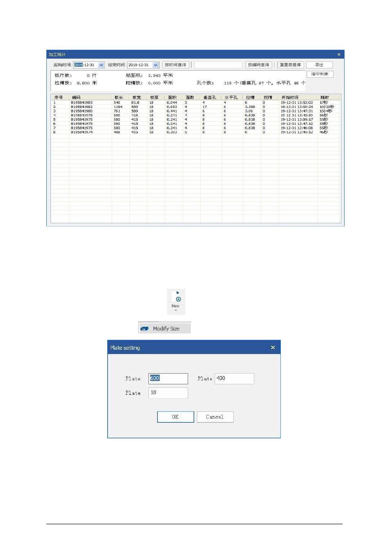
5.Processing statistics
Click "Processing Statistics" to open the processing statistics list, in which you can view the
relevant information of the processed plates and the processing
The number of boards, the number of areas. The number of grooves, the number of grooves,
the number of holes, and the related processed information can also be queried by time and plate
code.
-7-
3.2 Edit
1.Plate settings
Click the drop-down box of "New"
, click , set the length, width, and thickness of the
sheet in the pop-up dialog box
, and click OK.
2. Vertical hole
-8-
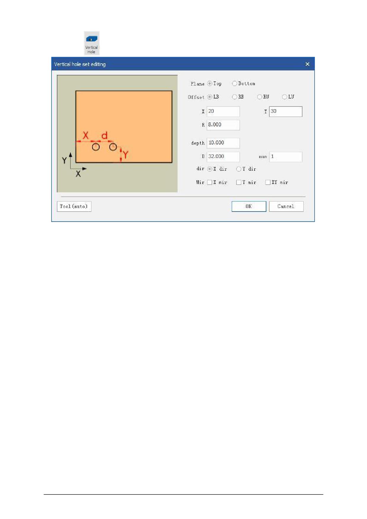
C lick Add “
”, Set in popup dialog side 。
Partial opposite Reference: In order to facilitate location of the sizing orifice, the flexibility to
choose different reference points, select the lower left corner, lower right corner, the upper right
corner or upper left corner position as a reference point editing hole.
Offset value X: the X coordinate of the hole position, fill in a positive number.
Offset value Y: the Y coordinate of the hole position, fill in a positive number.
Hole diameter: the diameter of the hole, fill in a positive number. Processing depth: the depth
of the hole position, fill in a positive number.
Array spacing: the offset value of the next hole from the hole position. Number of arrays:
Number of holes.
Arrangement direction: the direction of multiple hole arrays, you can choose X direction or Y
direction.
Mirror image: The hole can be mirrored symmetrically in X, Y or XY directions.
-9-
3.Horizontal hole
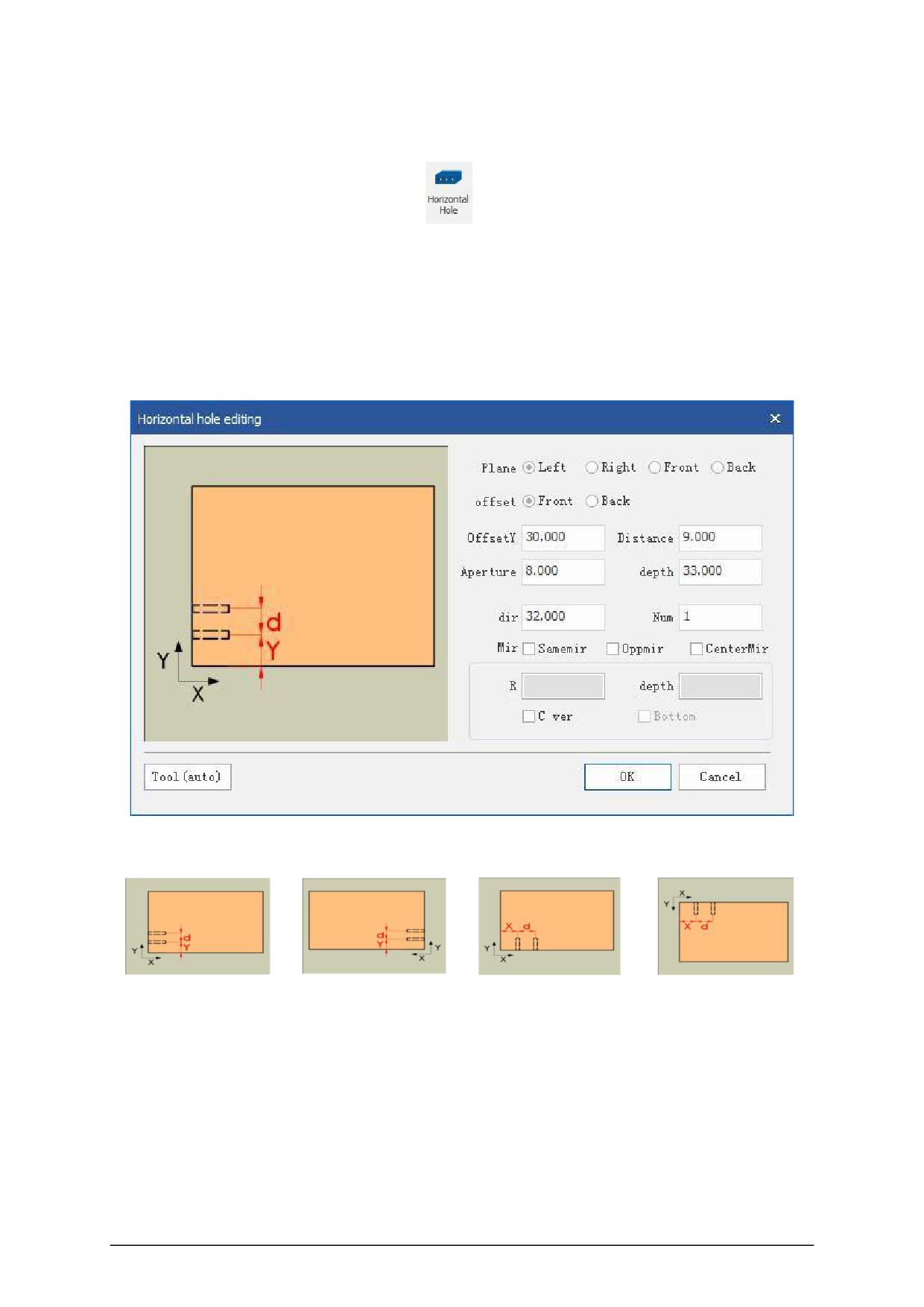
Click the icon to add "horizontal hole"
and set it in the pop-up dialog box.
First select the added surface, you can add the front side, rear door, left side, and right side.
When selecting the offset reference, in order to facilitate the calculation of the size and set the
position and size of the hole, different reference planes can be flexibly selected.
Set the offset value X/Y/Z, set the aperture and depth parameters, and click OK.
Side:According need add side
Left side
Right side
Front side
Back side
Offset reference: In order to conveniently set the position and size of the hole, different
reference points can be flexibly selected, and the lower left corner, lower right corner, upper left
corner or upper right corner can be selected as the reference point for editing the hole position.
Offset value X: the X coordinate of the hole position, fill in a positive number.
Offset value Y: the Y coordinate of the hole position, fill in a positive number.
- 10 -
Distance from bottom surface: the height of the bottom surface of the horizontal hole (for
example, if the current plate thickness is 18, if you fill in 9, the hole will be opened in the middle of
the plate thickness), and fill in a positive number.
Aperture: The diameter of the hole, fill in a positive number.
Processing depth: the depth of the hole position, fill in a positive number.
Array spacing: the offset value of the next hole from the hole position.
Number of arrays: Number of holes.
Arrangement direction: the direction of multiple hole arrays, you can choose X direction or Y
direction.
Mirroring: The hole can be mirrored symmetrically according to the X direction, Y direction or
XY direction.
Create vertical hole: You can create three and one hole by checking.
4.Horizontal slot
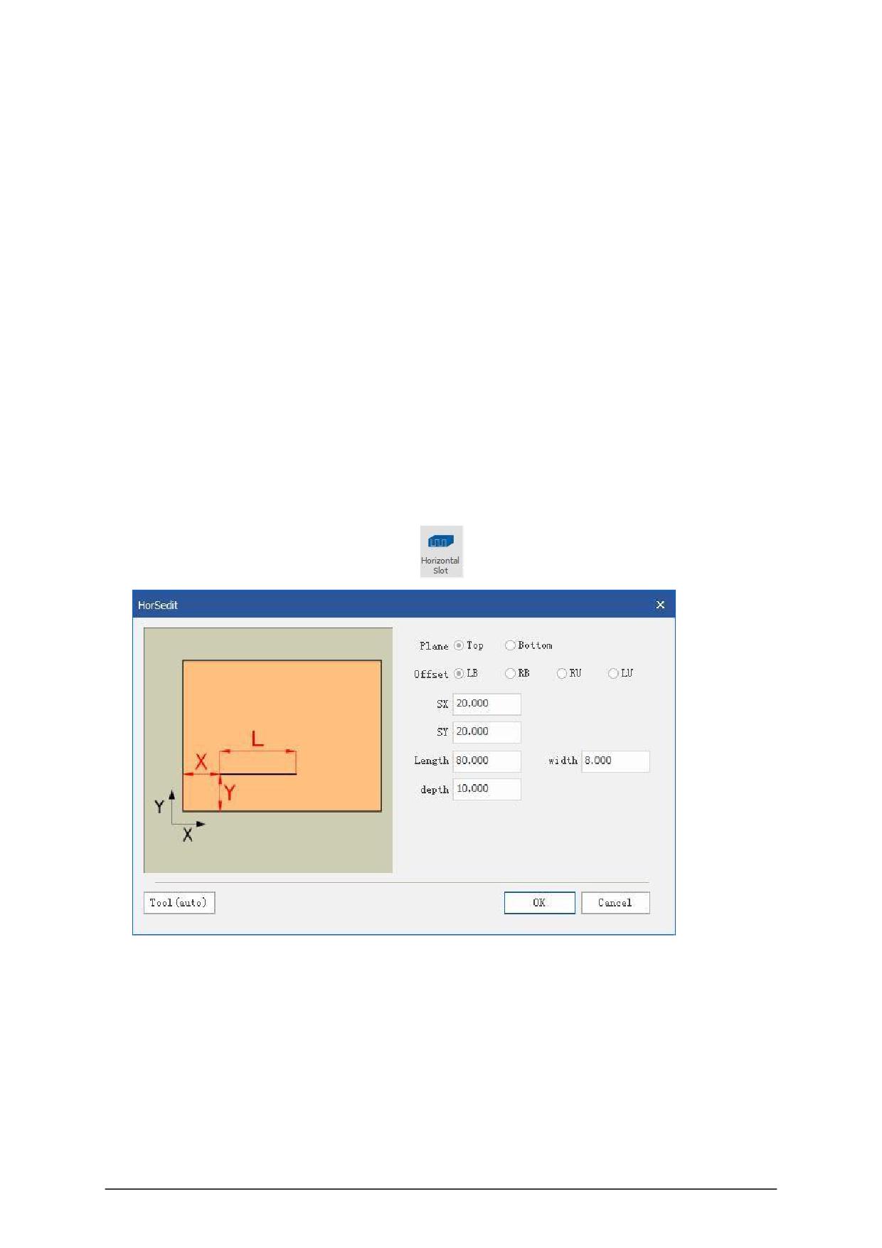
Click the icon added by "Horizontal Slot"
and set in the pop-up dialog box.
Owned surface: add to the top or bottom surface as needed;
Offset reference: In order to conveniently set the position and size of the hole, different
reference points can be flexibly selected, and the lower left corner, lower right corner, upper left
corner or upper right corner can be selected as the reference point for editing the hole position.
Starting point X: the X coordinate of the starting point of the horizontal slot, set to 0 for the
pull-through slot.
- 11 -
Starting point Y: the Y coordinate of the distance between the center of the horizontal groove
and the edge of the board.
Length: The length of the horizontal slot, fill in a positive number.
Slot width: the width of the slot, fill in a positive number.
Processing depth: the depth of the groove, fill in a positive number.
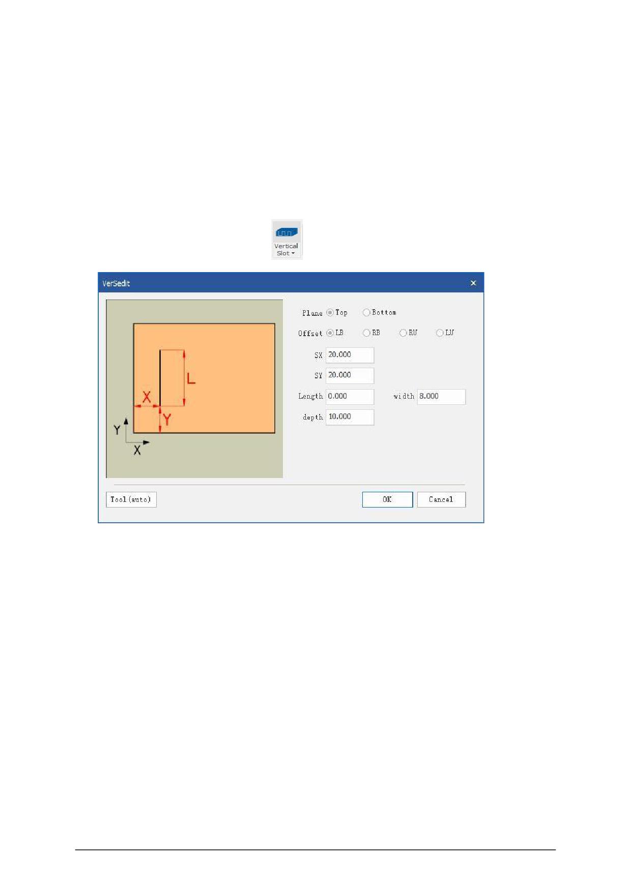
5.Vertical slot
Click the icon to add "Vertical Slot"
and set it in the pop-up dialog box.
Owning surface: Add to the top or bottom surface as needed.
Offset reference: In order to conveniently set the position and size of the hole, different
reference points can be flexibly selected, and the lower left corner, lower right corner, upper left
corner or upper right corner can be selected as the reference point for editing the hole position.
Starting point X: the X coordinate of the distance between the center of the vertical slot and
the edge of the board.
Starting point Y: It is the Y coordinate of the starting point of the vertical slot, and the
pull-through slot is set to 0.
Length: The length of the horizontal slot, fill in a positive number.
Slot width: the width of the slot, fill in a positive number.
Processing depth: the depth of the groove, fill in a positive number.
- 12 -
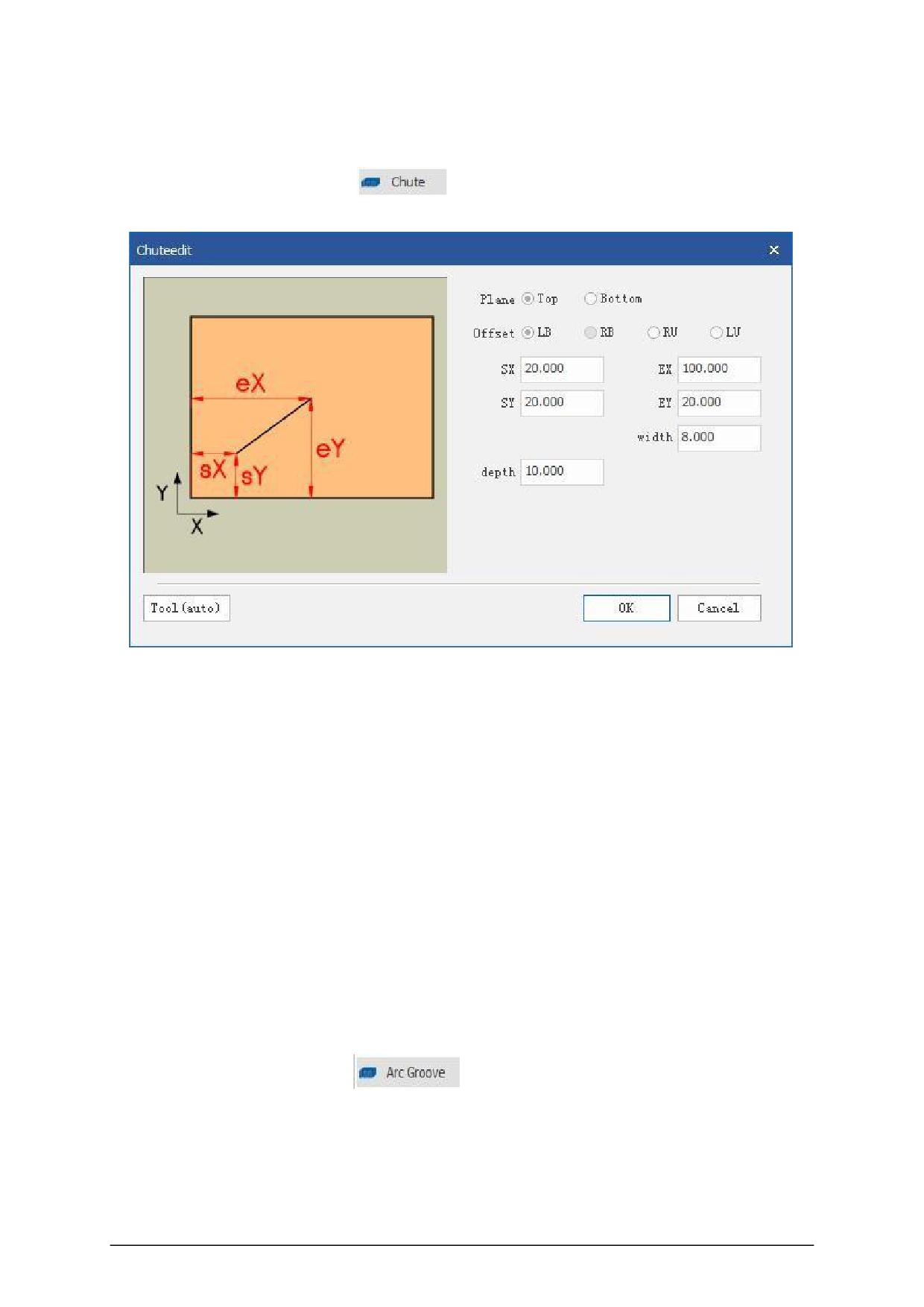
6.Chute
Click the icon to add "Chute"
and set it in the pop-up dialog box.
Owning surface: Add to the top or bottom surface as needed.
Offset reference: In order to conveniently set the position and size of the hole, different
reference points can be flexibly selected, and the lower left corner, lower right corner, upper left
corner or upper right corner can be selected as the reference point for editing the hole position.
Starting point X: X coordinate of the starting point of the chute,
Starting point Y: Y coordinate of the starting point of the chute.
End point X: X coordinate of the end point of the chute,
End point Y: Y coordinate of the end point of the chute.
Slot width: the width of the slot, fill in a positive number.
Processing depth: the depth of the groove, fill in a positive number.
7.Arc slot
Click the icon to add "arc groove"
and set in the pop-up dialog box.
- 13 -
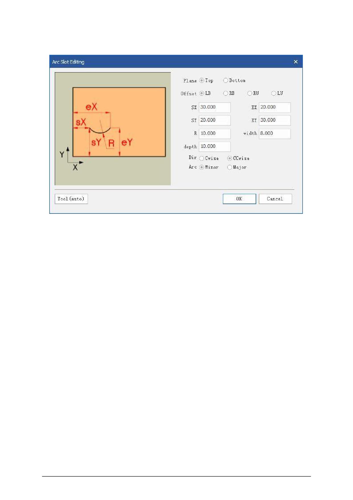
Owning surface: Add to the top or bottom surface as needed.
Offset reference: In order to conveniently set the position and size of the hole, different
reference points can be flexibly selected, and the lower left corner, lower right corner, upper
left corner or upper right corner can be selected as the reference point for editing the hole
position.
Starting point X: X coordinate of the starting point of the arc groove, Starting point Y: Y
coordinate of the starting point of the arc groove.
End point X: X coordinate of the end point of the arc slot , end point Y: Y coordinate of the end
point of the arc slot.
Arc: The arc with the center angle less than 180 degrees is selected as the inferior arc, and
the arc with the center angle greater than 180 degrees is the best.
Direction: Choose clockwise and counterclockwise as needed.
Slot width: the width of the slot, fill in a positive number.
Processing depth: the depth of the groove, fill in a positive number.
8.Round groove
- 14 -
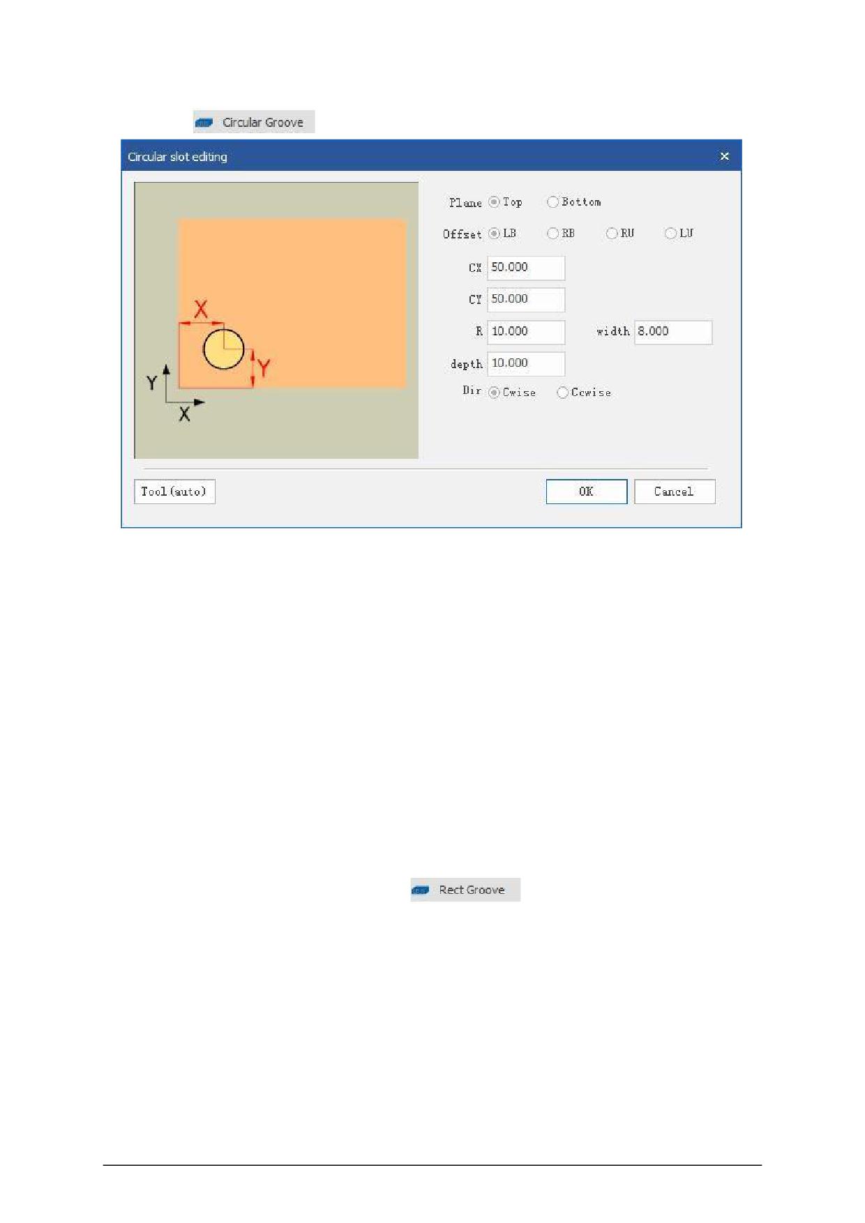
C lick Add
, Set in popup dialog 。
Owning surface: Add to the top or bottom surface as needed.
Offset reference: In order to conveniently set the position and size of the hole, different
reference points can be flexibly selected, and the lower left corner, lower right corner, upper left
corner or upper right corner can be selected as the reference point for editing the hole position.
Center X: X coordinate of the center of the slot,
Center Y: The Y coordinate of the center of the groove.
Direction: Choose clockwise and counterclockwise as needed.
Slot width: the width of the slot, fill in a positive number.
Processing depth: the depth of the groove, fill in a positive number.
9.Rectangular slot
Click the icon to add a "rectangular slot"
and set in the pop-up dialog box.
- 15 -
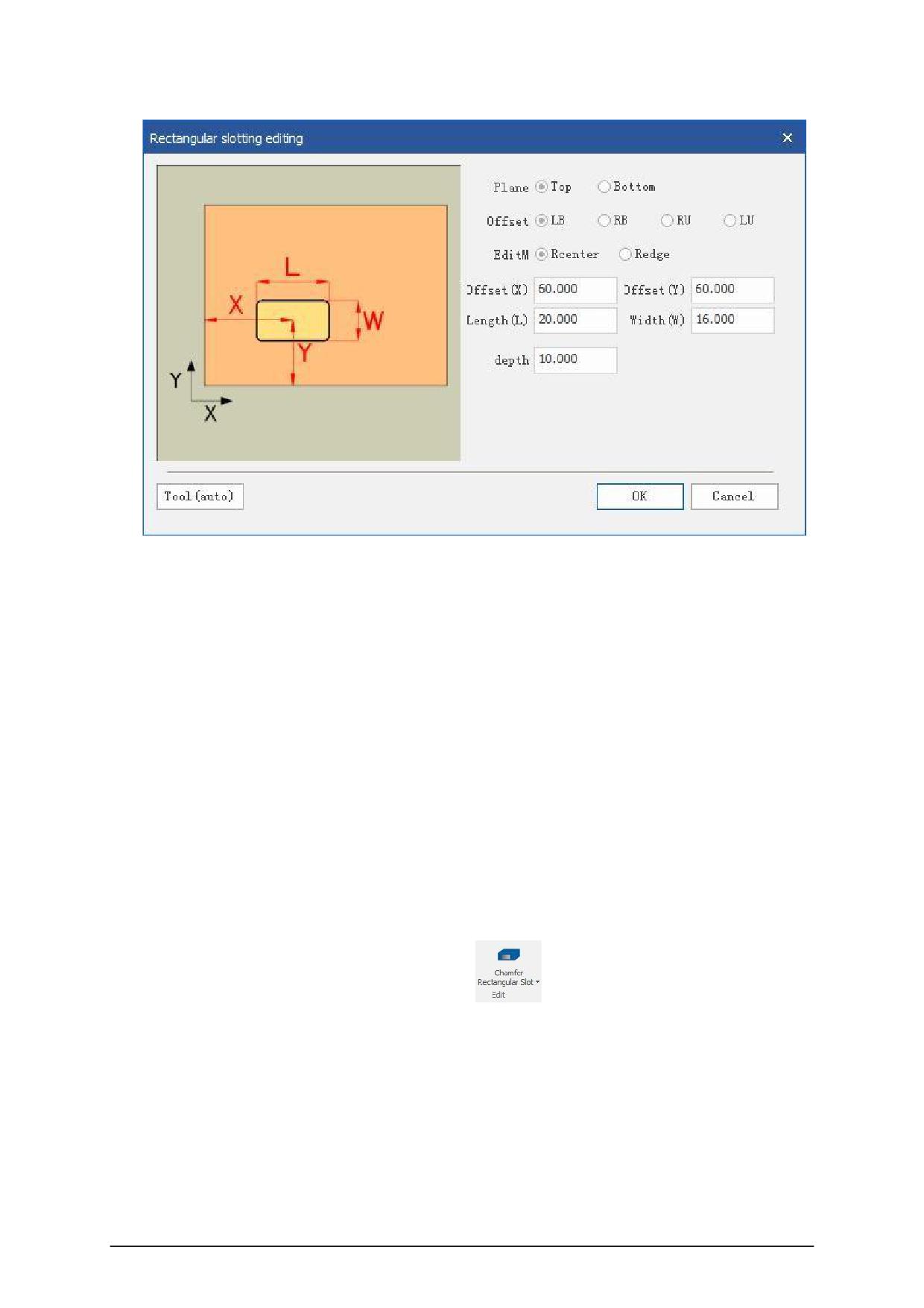
Owned surface: add to the top or bottom surface as needed;
Offset reference: In order to conveniently set the position and size of the hole, different
reference points can be flexibly selected, and the lower left corner, lower right corner, upper left
corner or upper right corner can be selected as the reference point for editing the hole position.
Rectangle center X: X coordinate of the rectangle center,
Rectangle center Y: Y coordinate of the center of the rectangle.
Length (X): The length of the rectangle in the X direction,
Width (Y): The width of the rectangle in the Y direction.
Processing depth: the depth of the groove, fill in a positive number.
10.Dig a circular groove
Click the icon to add the "dig circular groove"
and set it in the pop-up dialog box.
- 16 -
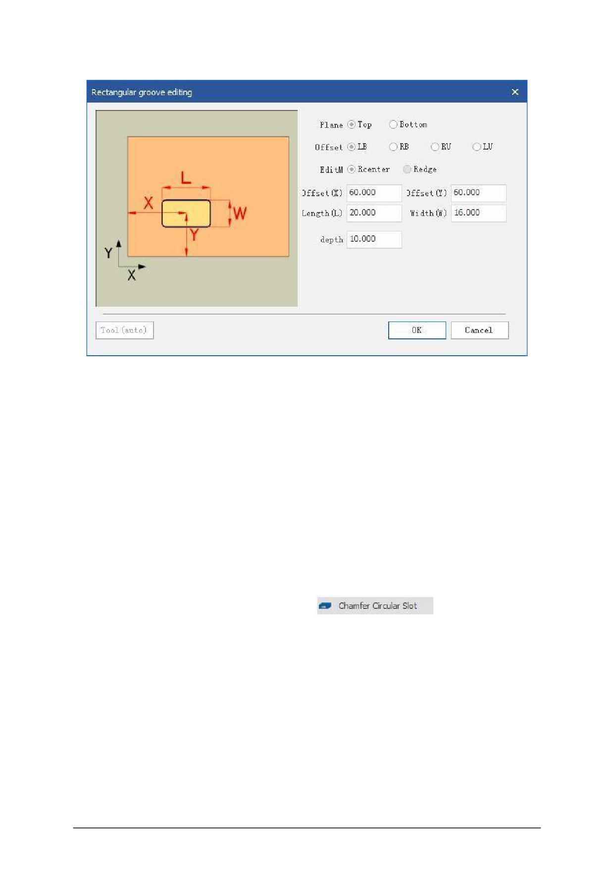
Owned surface: add to the top or bottom surface as needed;
Offset reference: In order to conveniently set the position and size of the hole, different
reference points can be flexibly selected, and the lower left corner, lower right corner, upper left
corner or upper right corner can be selected as the reference point for editing the hole position.
Rectangle center X: X coordinate of the center of the rectangle,Rectangle center Y: Y
coordinate of the center of the rectangle.
Length (X): the length of the rectangle in the X direction, width (Y): the width of the rectangle
in the Y direction.
Processing depth: the depth of the groove, fill in a positive number.
11.Dig a circular groove
Click the icon to add the "dig circular groove"
and set it in the
pop-up dialog box.
- 17 -
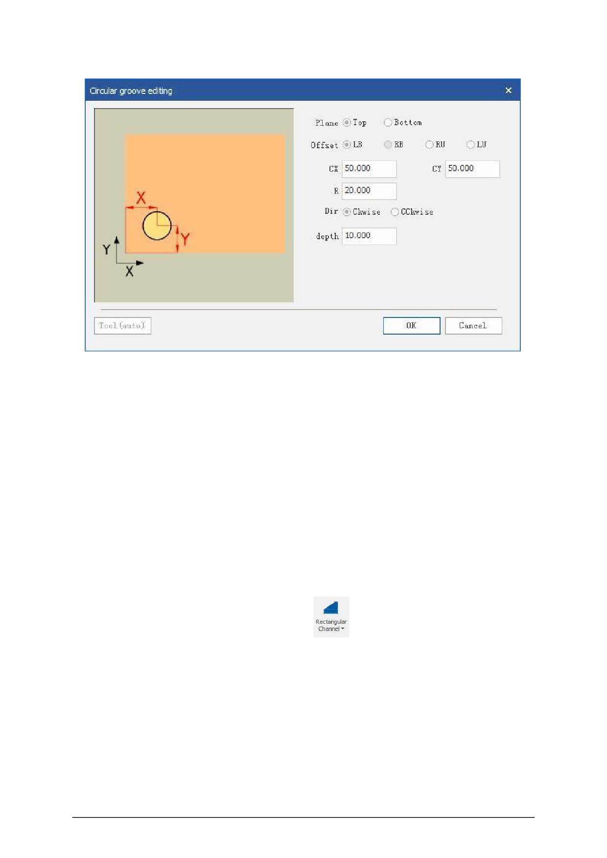
Owning surface: Add to the top or bottom surface as needed.
Offset reference: In order to conveniently set the position and size of the hole, different
reference points can be flexibly selected, and the lower left corner, lower right corner, upper left
corner or upper right corner can be selected as the reference point for editing the hole position.
Center X: X coordinate of the center of the circular groove, Center Y: Y coordinate of the
center of the circular groove.
Radius: The radius of the circular groove.
Direction: Choose clockwise and counterclockwise as needed.
Processing depth: the depth of the groove, fill in a positive number.
12.Rectangle missing corner milling type
Click the icon to add "rectangular corner slot"
and set in the pop-up dialog box.
- 18 -
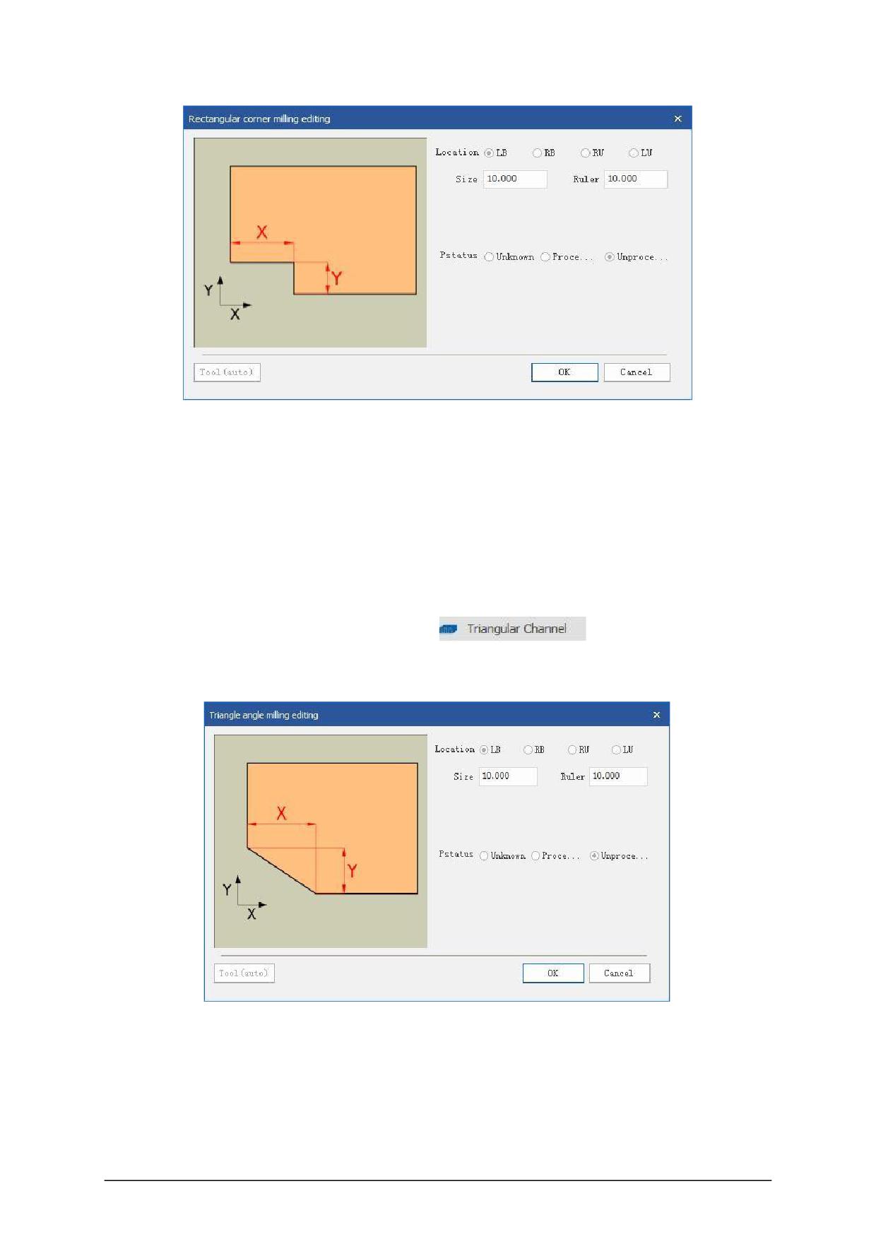
Offset reference: In order to conveniently set the position and size of the hole, different
reference points can be flexibly selected, and the lower left corner, lower right corner, upper left
corner or upper right corner can be selected as the reference point for editing the hole position.
Dimension X: Rectangle length X value,
Dimension Y: Rectangle width Y value.
13.Triangular missing corner milling type
Click the icon to add "triangular corner slot"
and set in the pop-up
dialog box.
Offset reference: In order to conveniently set the position and size of the hole, different
reference points can be flexibly selected, and the lower left corner, lower right corner, upper left
corner or upper right corner can be selected as the reference point for editing the hole position.
Size X: triangle length X value, size Y: triangle height Y value.
- 19 -
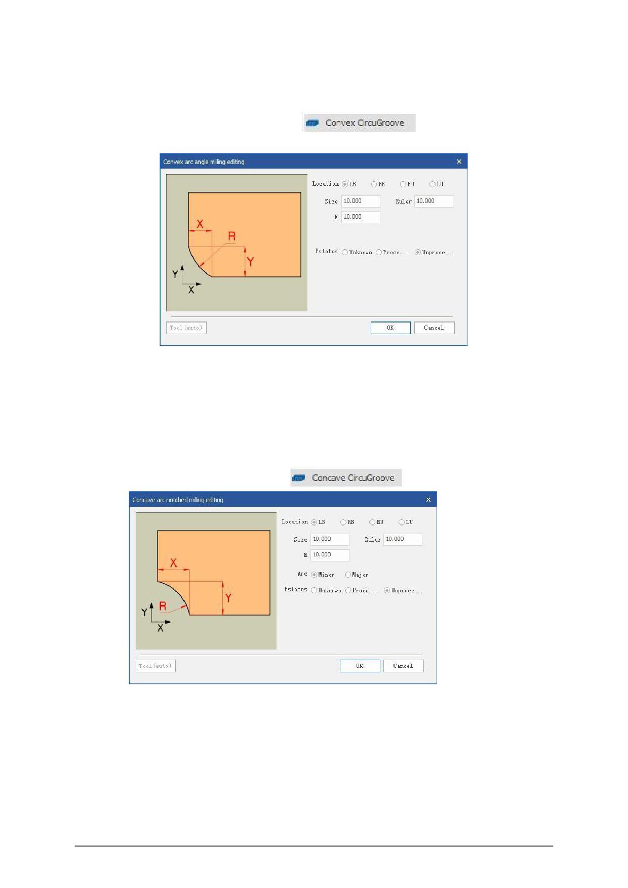
14.Convex arc missing corner milling type
Click Add "convex corners groove Icons"
in the pop-up dialog box.
Offset reference: In order to conveniently set the position and size of the hole, different
reference points can be flexibly selected, and the lower left corner, lower right corner, upper left
corner or upper right corner can be selected as the reference point for editing the hole position.
Dimension X: arc X coordinate value,
dimension Y: arc Y coordinate value.
15.Concave arc missing corner milling type
Click Add "cove corner groove Icons"
in the pop-up dialog box.
Offset reference: In order to conveniently set the position and size of the hole, different
reference points can be flexibly selected, and the lower left corner, lower right corner, upper left
corner or upper right corner can be selected as the reference point for editing the hole position.
Size X: arc X coordinate value, size Y: arc Y coordinate value.
Arc: If the arc is less than 180, select the minor arc, and if the arc is greater than 180 degrees,
select the superior arc.
- 20 -
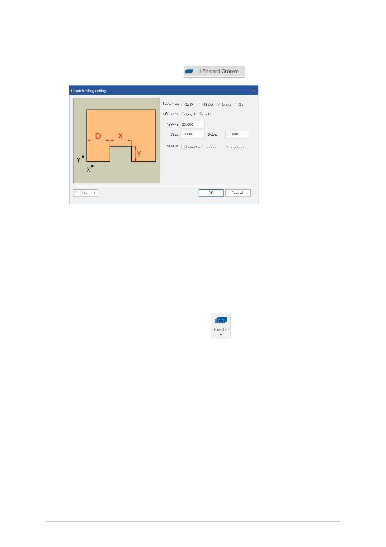
16.U-shaped groove missing angle milling type
Click the icon to add "U -shaped groove"
and set in the pop-up dialog
box.
Position: Select the location of the U-shaped groove, you can choose the left, right, front, and
back.
Offset reference: In order to conveniently set the position and size of the hole, different
reference points can be selected flexibly, and left and right reference points can be selected.
Offset position: the distance from the reference point.
Dimension X: Rectangle length X value, Dimension Y: Rectangle width Y value.
17.Invisible
① Click the Add icon "invisible piece"
in the pop-up dialog box
set, Lockdowel invisible pieces. invisible editing(LK).
- 21 -
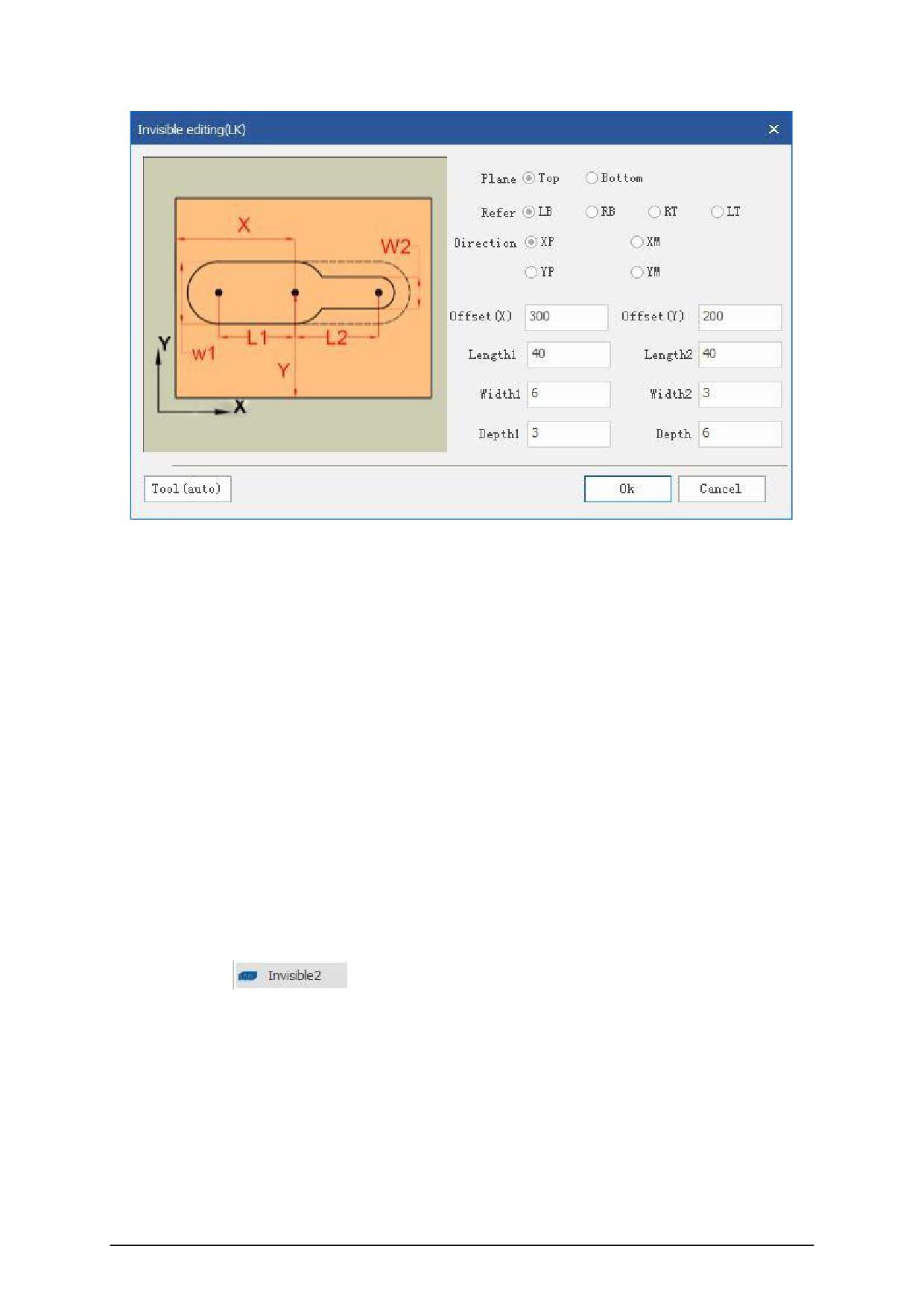
Owning surface: Add to the top or bottom surface as needed.
Offset reference: In order to conveniently set the position and size of the slot, different
reference points can be flexibly selected, and the lower left corner, lower right corner, upper left
corner or upper right corner can be selected as the reference point for editing the slot position.
Processing direction: X positive direction, X negative direction, Y positive direction, Y negative
direction can be selected according to the selection.
Offset value X: the X coordinate of the slot, fill in a positive number, and offset Y: the Y
coordinate of the slot, fill in a positive number.
Length L1: The length of the slot, fill in a positive number, Length L2: The length of the slot, fill
in a positive number.
Width W1: The width of the slot, fill in a positive number, Width W2: The width of the slot, fill in
a positive number.
Processing depth D1: the depth of the groove, fill in a positive number. Processing depth D2:
the depth of the groove, fill in a positive number.
② Click Add
,Set in popup dialog, invisible editing(MDY).
- 22 -
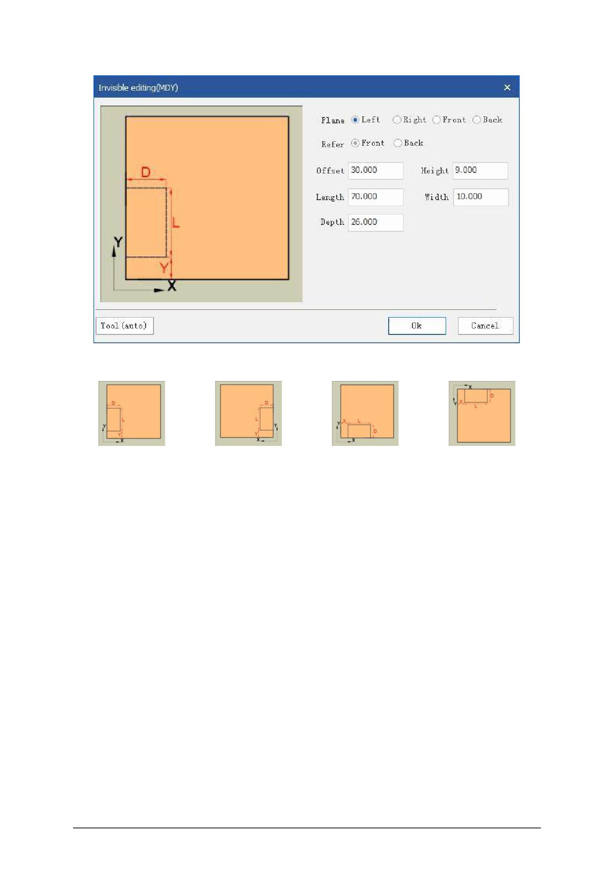
Owning face: Add face as needed.
Left side
Right side
Front side
Back side
Offset reference: In order to conveniently set the position and size of the hole, different
reference points can be flexibly selected, and the lower left corner, lower right corner, upper left
corner or upper right corner can be selected as the reference point for editing the hole position.
Offset value X: the X coordinate of the slot, fill in a positive number,
Offset value Y: the Y coordinate of the slot, fill in a positive number.
Distance from the bottom: the height of the slot from the bottom (for example, if the current
plate thickness is 18, if you fill in 9, a hole will be made in the middle of the plate thickness), and fill
in a positive number.
Length: The length of the slot, fill in a positive number.
Slot width: the width of the slot, fill in a positive number.
Processing depth: the depth of the hole position, fill in a positive number.
3.3 DXF import
First select DXF (custom) in the file type option bar.
- 23 -
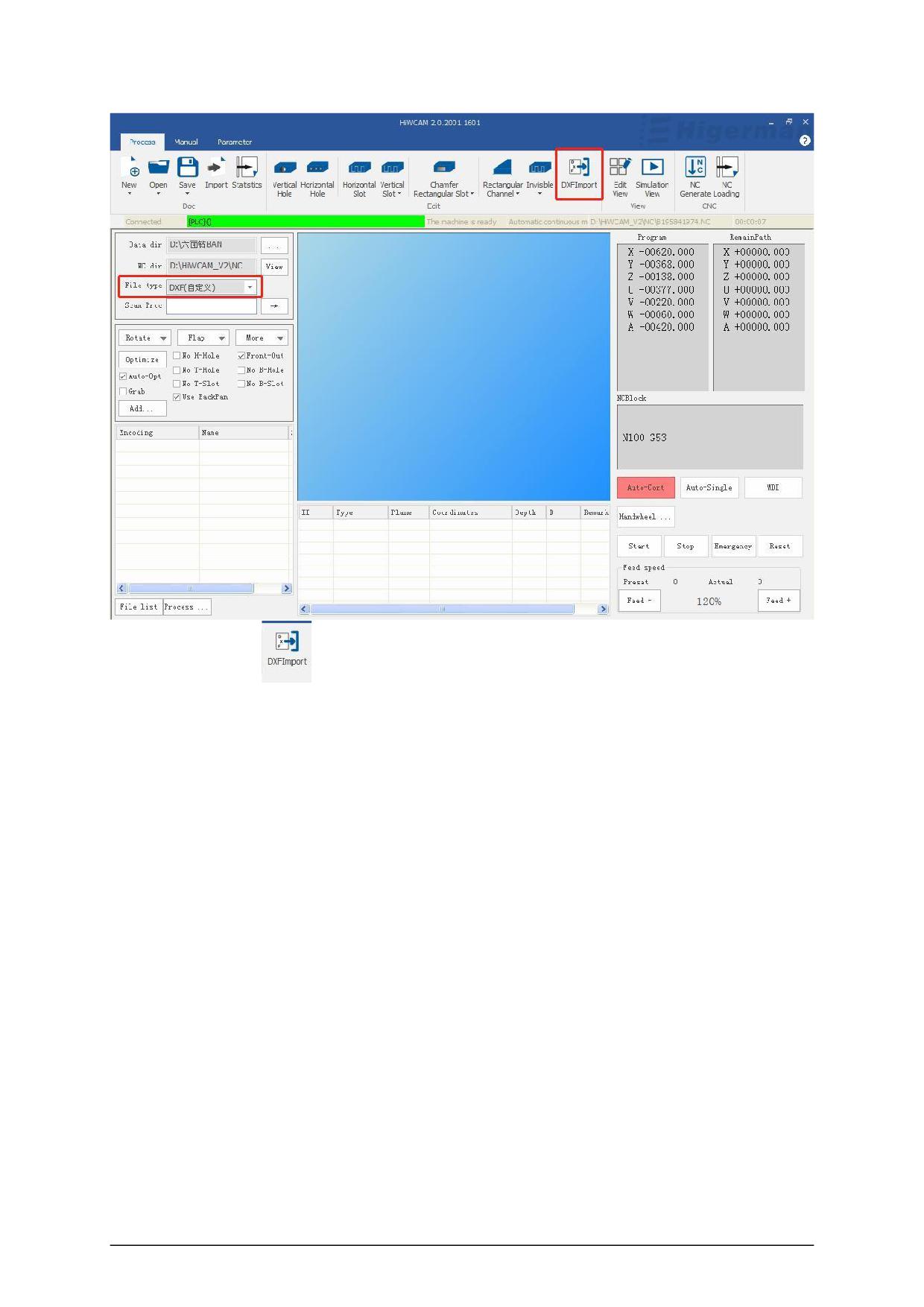
Click "DXF import"
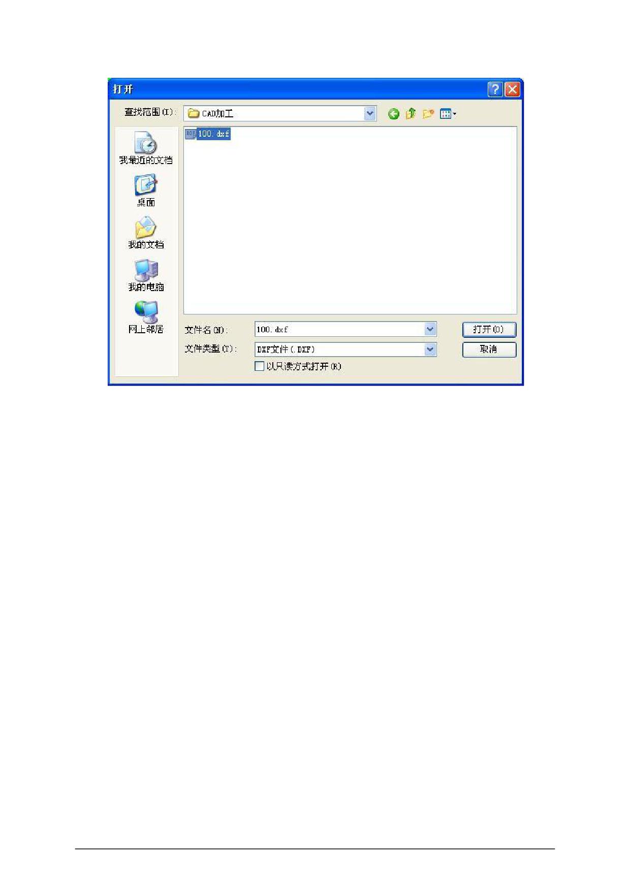
,a dialog box pops up, select the DXF file in the corresponding directory, you can choose to
import, and draw the CAD drawing according to the DXF definition format of Higerman . (Note:
the drawing can only be imported successfully according to the content agreement!)
- 24 -
- 25 -
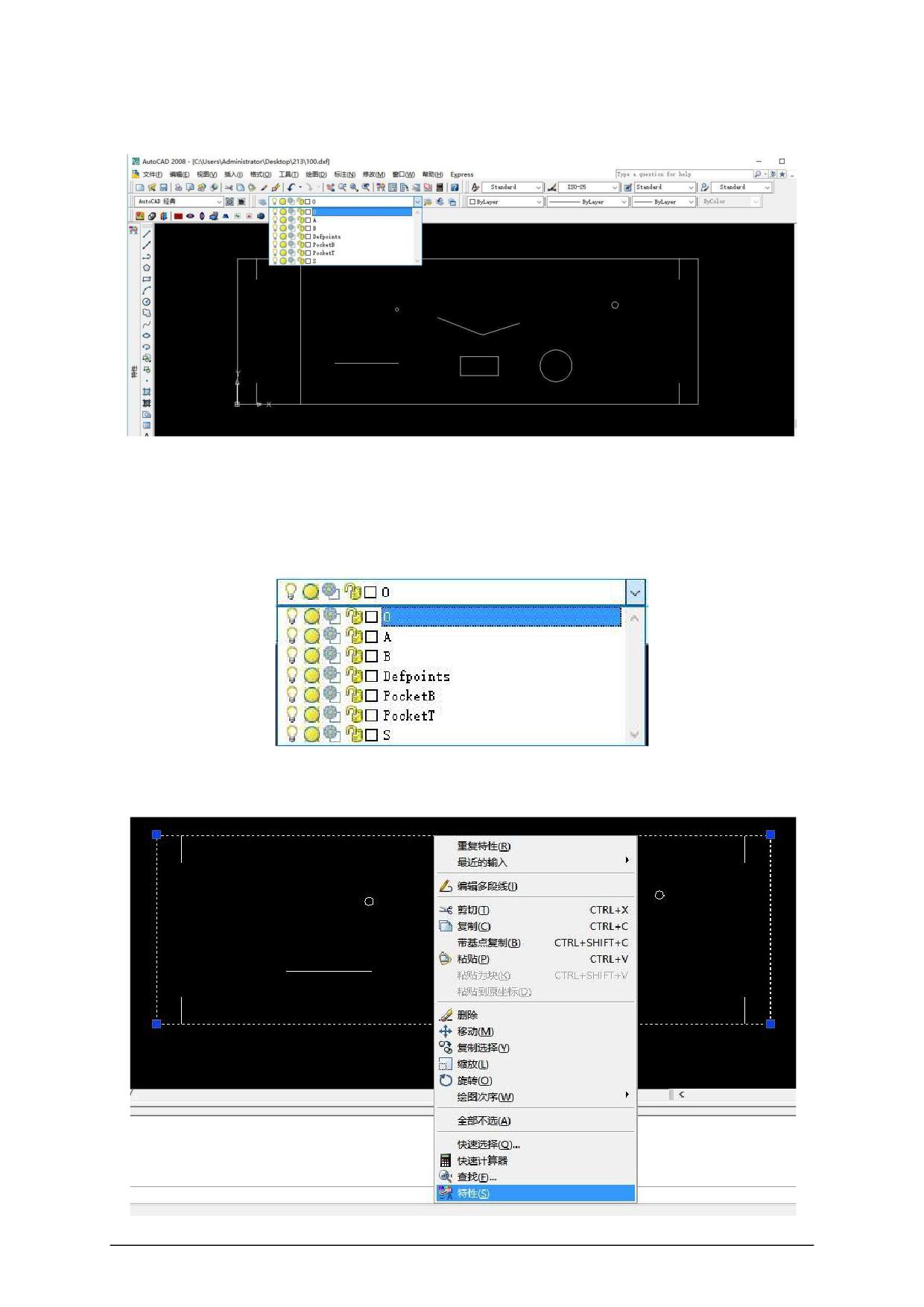
The conventions of the layers and their contents in the DXF file are as follows:
◆ Level 0 , profile information of the board
●Use the polyline to provide the size information of the outer rectangle, and the thickness
parameter of the polyline to provide the sheet thickness information.
Select the outer contour with the mouse, right-click the mouse, open the feature,
find Thickness, and modify the value to modify the information of the sheet thickness.
- 26 -
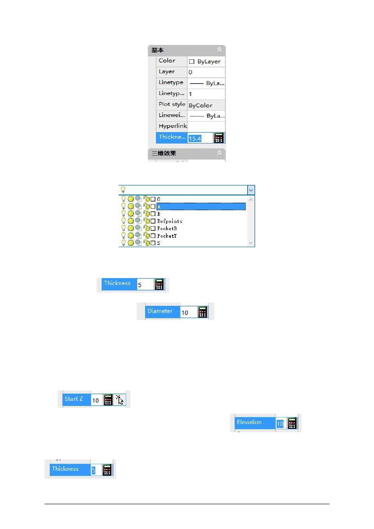
◆ A layer, which means top surface processing
●Circle is a hole , the thickness parameter of the circular element indicates the depth of the
hole, and the size of the circle indicates the size of the tool diameter used.
Hole depth :
Cutter diameter big small:
●Polyline, straight line and arc indicate represent slotting processing . The Z- direction
value parameter of straight line and arc is slot width, and the elevation parameter of polyline is
slot width. The thickness parameters of straight line, arc, and polyline indicate depth.
The Z- direction value parameter of straight line and arc is the slot width:
The elevation parameter of the polyline is the slot width:
The thickness parameters of straight lines, arcs, and polylines indicate depth:
- 27 -
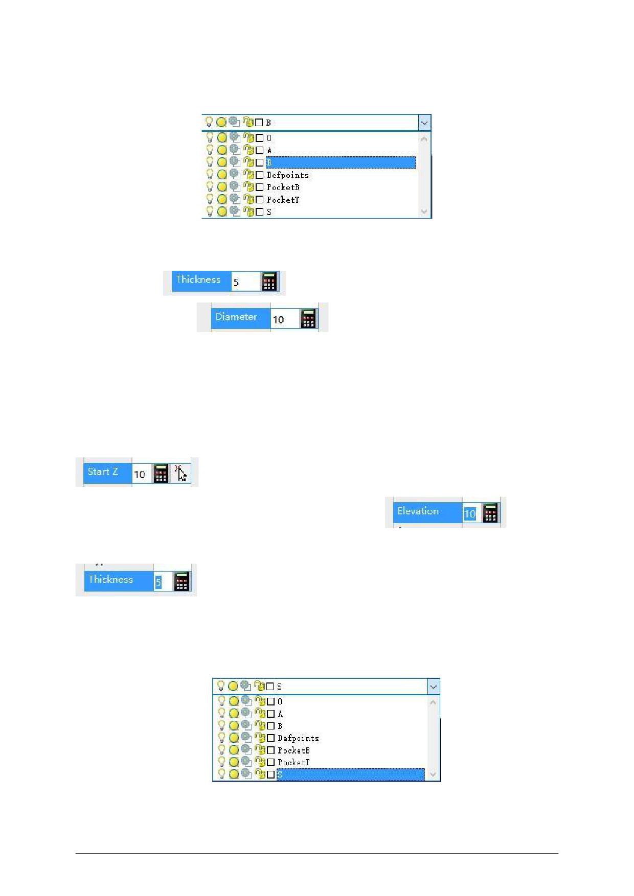
◆ B layer, a bottom surface of the processing
●Circle is a hole , the thickness parameter of the circular element indicates the depth of the
hole, and the size of the circle indicates the size of the tool diameter used.
Hole depth:
Tool diameter size:
●Polyline, straight line and arc indicate represent grooving processing . The Z value
parameter of the straight arc is the slot width, and the elevation parameter of the polyline is the slot
width.
The thickness parameters of straight line, arc, and polyline indicate depth.
The Z- direction value parameter of straight line and arc is the slot width:
The elevation parameter of the polyline is the slot width:
The thickness parameters of straight lines, arcs, and polylines indicate depth:
◆ S layer, representing side processing, the straight line perpendicular to the contour line
is horizontal hole processing
●The thickness parameter of the straight line element represents the aperture, the length of
the straight line represents the depth, and the Z- direction value parameter represents the height
- 28 -
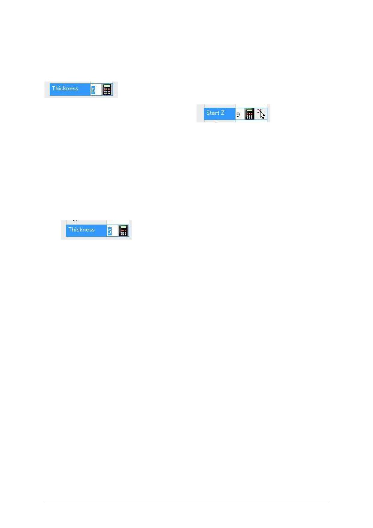
(the default is 0 means that the height of the horizontal hole is centered on the thickness of the
sheet).
The thickness parameter of the linear primitive indicates the aperture:
The Z- value parameter represents the height:
◆ PocketT and PocketB layers provide support for top and bottom grooving
●Use circles and polylines as grooving contours. The grooving processing parameters
are set by the main CAM program.
PocketT layer: top surface grooving
PocketB layer: bottom groove processing
The circle and polyline thickness parameters indicate the depth of the trench
:
- 29 -
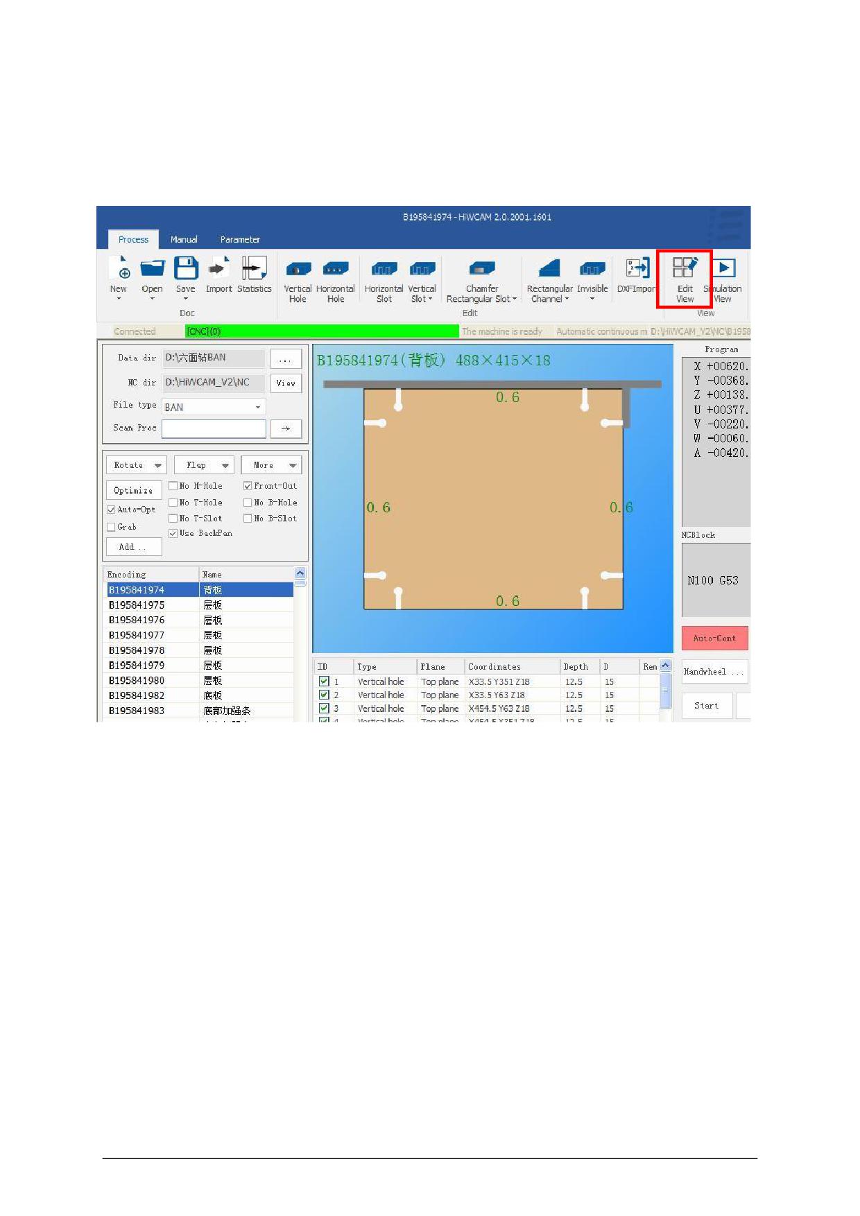
3.4 View
1.Edit view
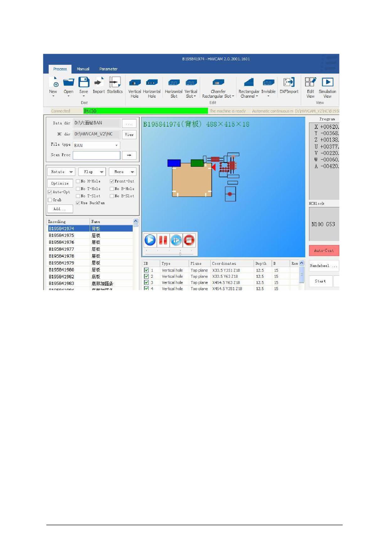
2.Simulation view
After the NC program is generated , the machining program can be simulated. Click the
"simulation view" icon to switch to the simulation interface, as shown below.
Click the button in the green control bar to control the simulation start, pause, fast forward,
stop, and also control the simulation processing speed.
Click to start the simulation, you can see the actual processing, the movement path of the
plate and the tool, the tool selection and other information in this interface.
- 30 -
- 31 -
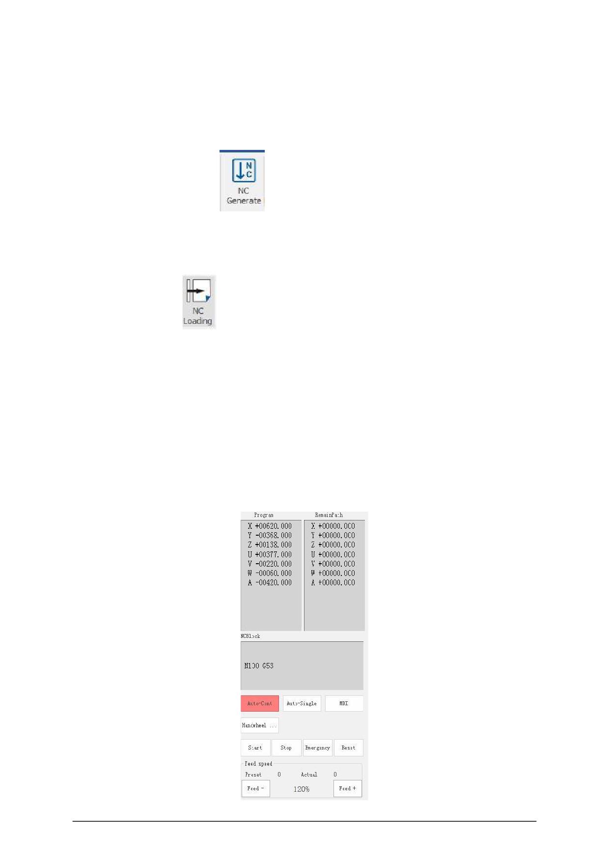
3.5 CNC operation
1.NC Generated
Click the "NC Generate"
icon in the figure below to indicate that the file has been
converted into a processing file.
2. NC loading
Click “N C Load”
icon will automatically load the program into the CNC , the right side
of the CNC operating area, select a good machine models and suitable processing speed, you
can press start to start the automatic execution of the program.
After the program is started, first the X- axis positioning will be lifted, and the fixture will move
to the optimized position in the program, and then after the operator places the plate in the position,
press "Start" or "Foot Switch" to automatically execute the program .
As shown in the figure below, the machine can be started, paused, emergency stopped, and
machine reset.
In the NC block box, the current program processing line will be displayed in real time.
- 32 -
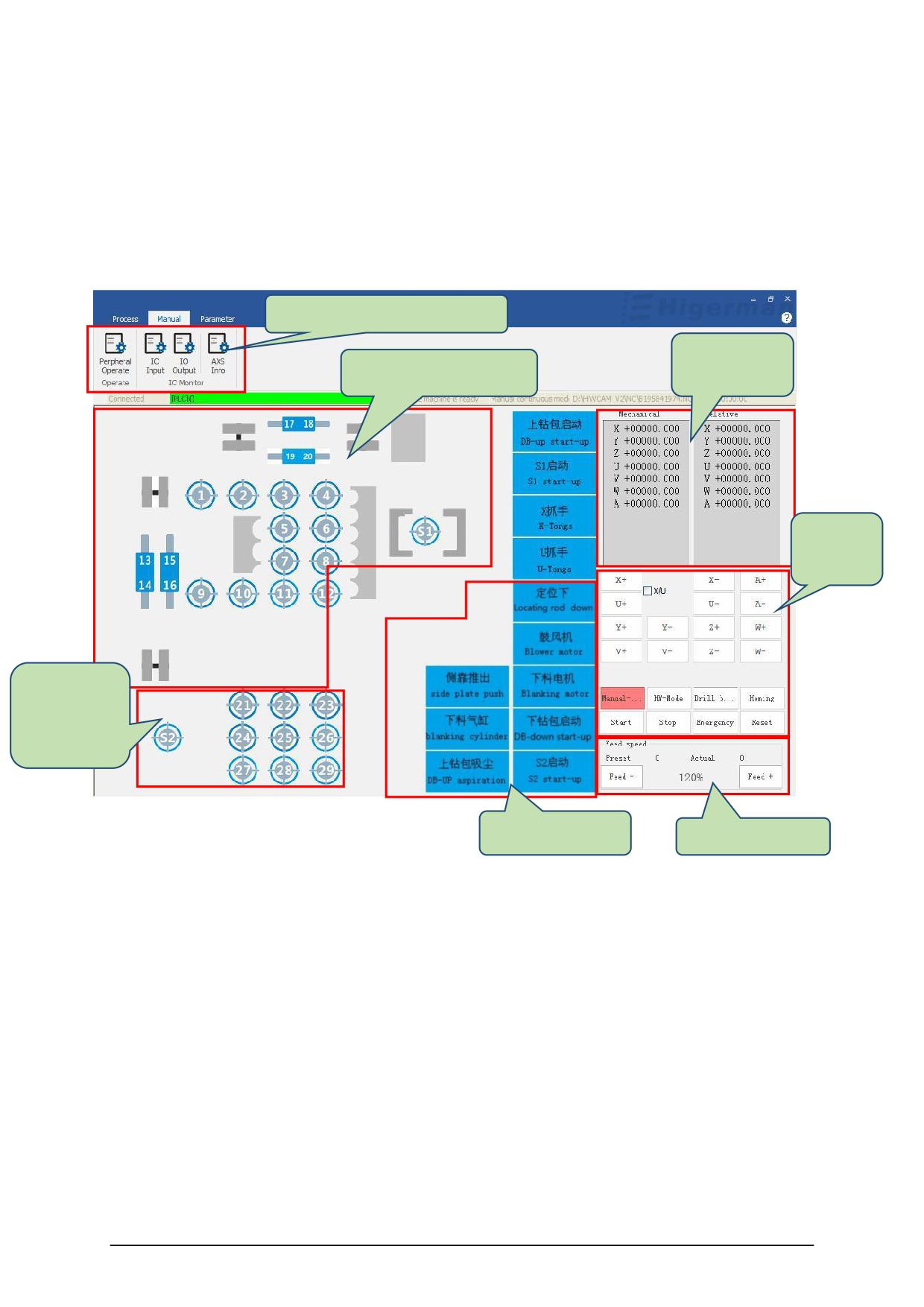
4.Manual
The manual interface includes peripheral operation, IO input, IO output, and AXS information.
4.1 Peripheral operation
Manual interface menu bar
Coordinate
Top drill manual operate
display area
Function
keypad
Bottom drill
manual
operate
Interface buttons
Speed set
◆ Manual operation area of
the upper and lower drilling package: you can manually
click the buttons of the tool, pressing plate, and spindle, the corresponding tool, pressing plate,
and the spindle will be hit, and click again to retract it.
◆ Function button area: Click the button, the function described in the corresponding picture
button will be output, click again to restore.
◆ Coordinate display area: It can display the coordinate values
of machine coordinates
and relative coordinates.
◆ Function key area: In the manual interface, you can switch the handwheel mode, return to
zero, reset coordinates, and move each axis.
◆ Speed selection: adjustable speed magnification.
- 33 -
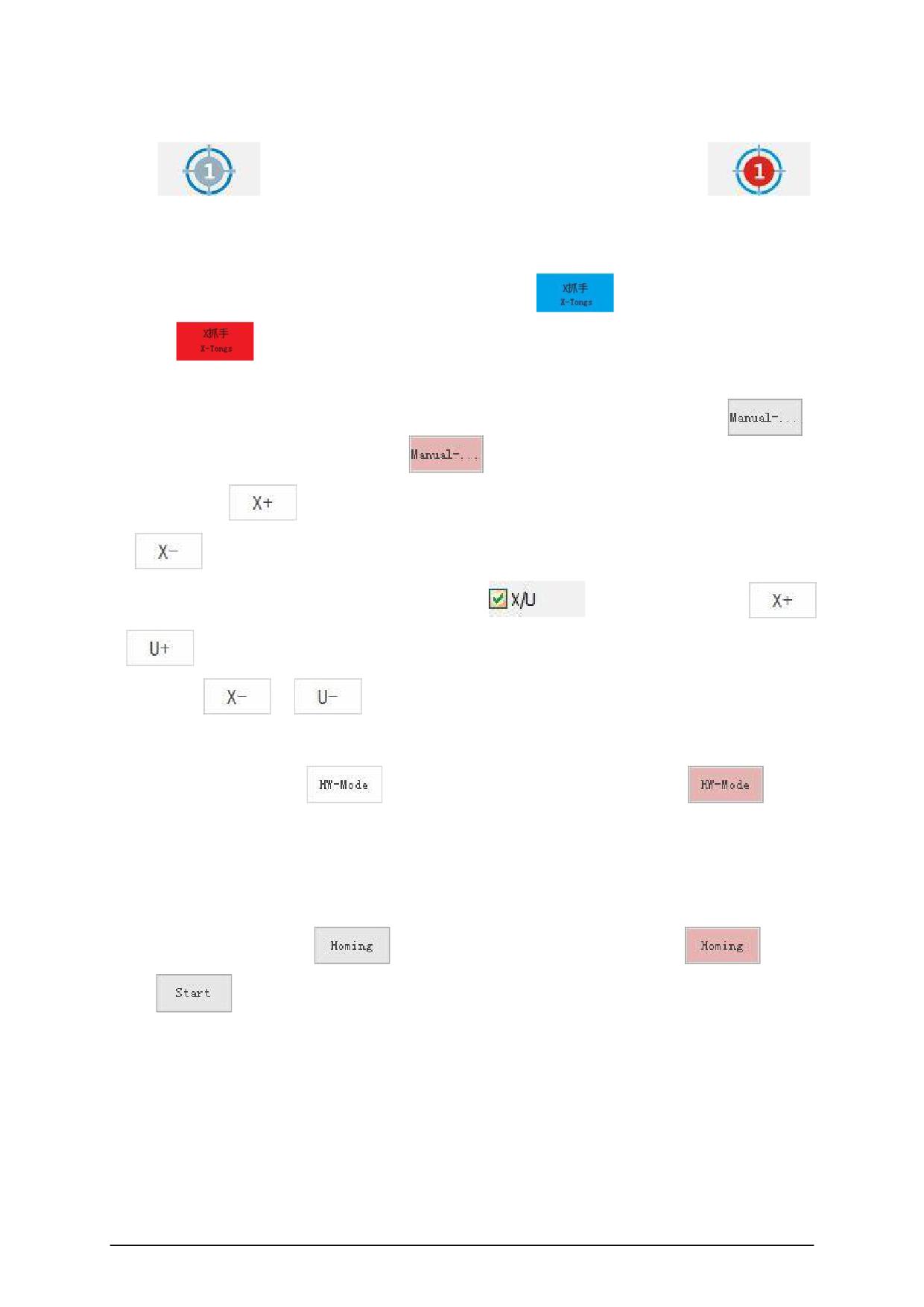
● Manual operation of the up and down drilling package: click the "button" of tool
No. 1
(default state) with the mouse , and the "button" becomes
,
indicating that tool No. 1 has been extended, click again to restore the default state, the tool is
retracted, and other pressing plate and spindle operations The same is true.
● Function button: mouse click on the "X gripper button"
(default state), the "button"
becomes
, indicating that the X gripper will be clamped, click again to restore the default
state, the gripper is released, the operation of other function buttons is the same.
● Manual continuous: When the machine tool is ready, click the "manual continuous"
,
the "manual continuous button" becomes
, and then click the axial buttons of each axis.
For example,
, the X axis will move in the positive direction. Click and
the
X axis will move in the negative direction. The operation of other manual moving
axes is the same. When the XU coupling is checked
and the mouse clicks
or
, the X axis and U axis will move in the positive direction at the same time, and the
mouse clicks
or
, the X axis and U axis will move in the negative direction at the
same time.
● Click "handwheel mode"
, the "handwheel mode button" becomes
, press
the button on the interface, enter the handwheel operation mode, and then use the axis selection
switch on the handwheel to choose between each axis, or through The override selection switch
adjusts the step distance of the handwheel feed. When the axis and step distance are determined,
the operation of each axis can be driven by shaking the hand wheel.
● Click "Return to zero"
, "Return to zero button" becomes
, click
"Start"
, the coordinate axis feeds at a fixed speed when returning to the machine origin,
until it returns to the origin position (for incremental machine tools, absolute value machine tools
do not Need to go back to origin).
● speed selection: by "ratio + " and "magnification - " self-adjust the feed speed override, the
maximum rate of 120% .
- 34 -
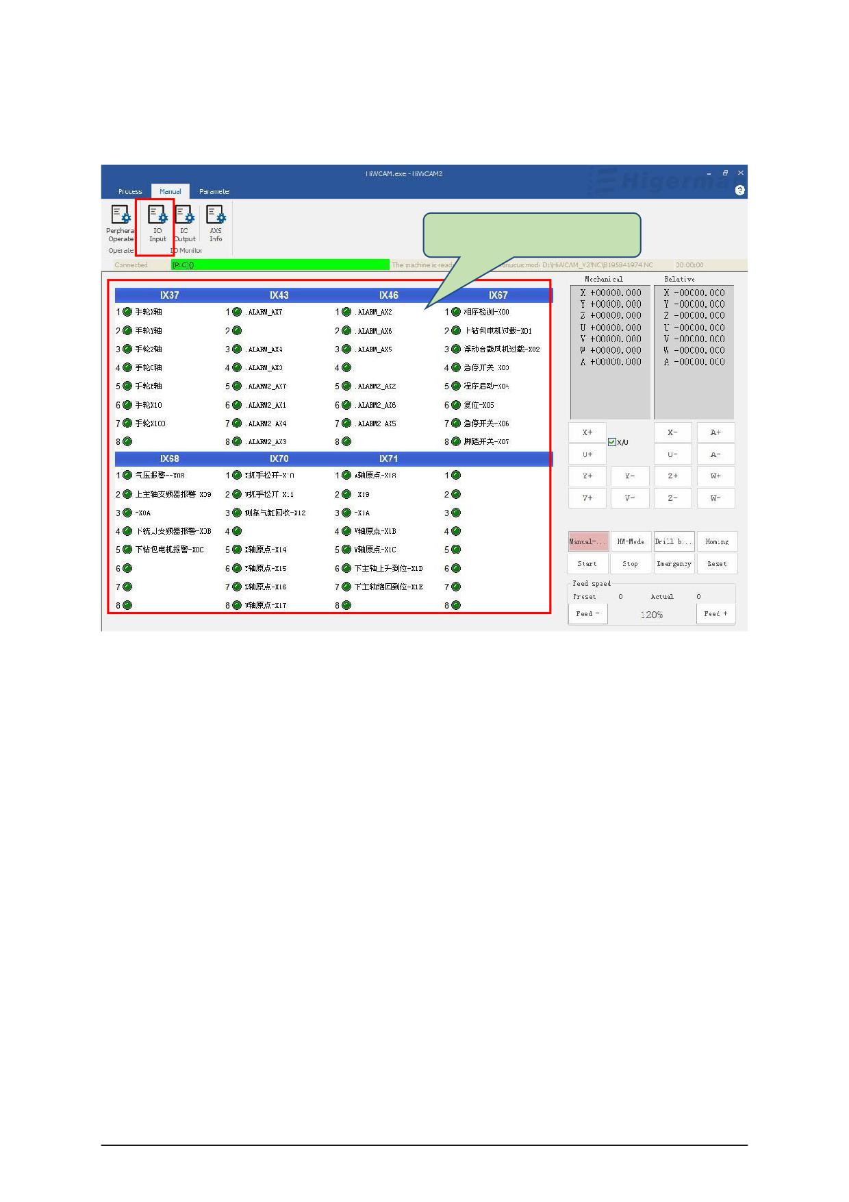
4.2 IO Input
IO input status display area
A state of IO input points can be monitored in this area .
4.3 IO Output
- 35 -
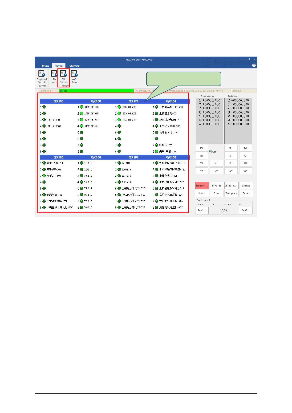
IO output status display area
A state of IO output points can be monitored in this area .
4.4 AXS information
This interface can monitor mechanical coordinates, feedback coordinates, absolute
coordinates, end coordinates, coordinate compensation, output voltage, following error,
position KV, feed speed, etc. We usually monitor the position KV , which is monitored when each
axis moves The KV value should be the same as the KV of each axis set by the machine
parameters . If it is not the same, an alarm will occur when the axis moves, for example, the axis
lag value is too large.
- 36 -
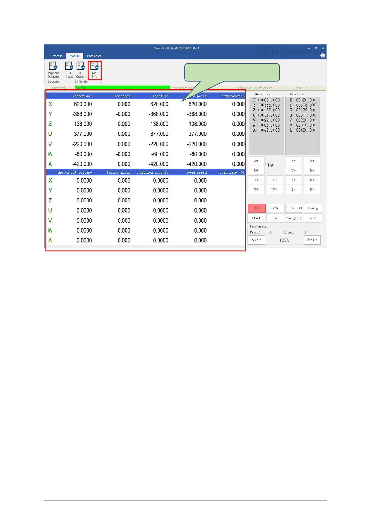
AXS monitoring display area
- 37 -
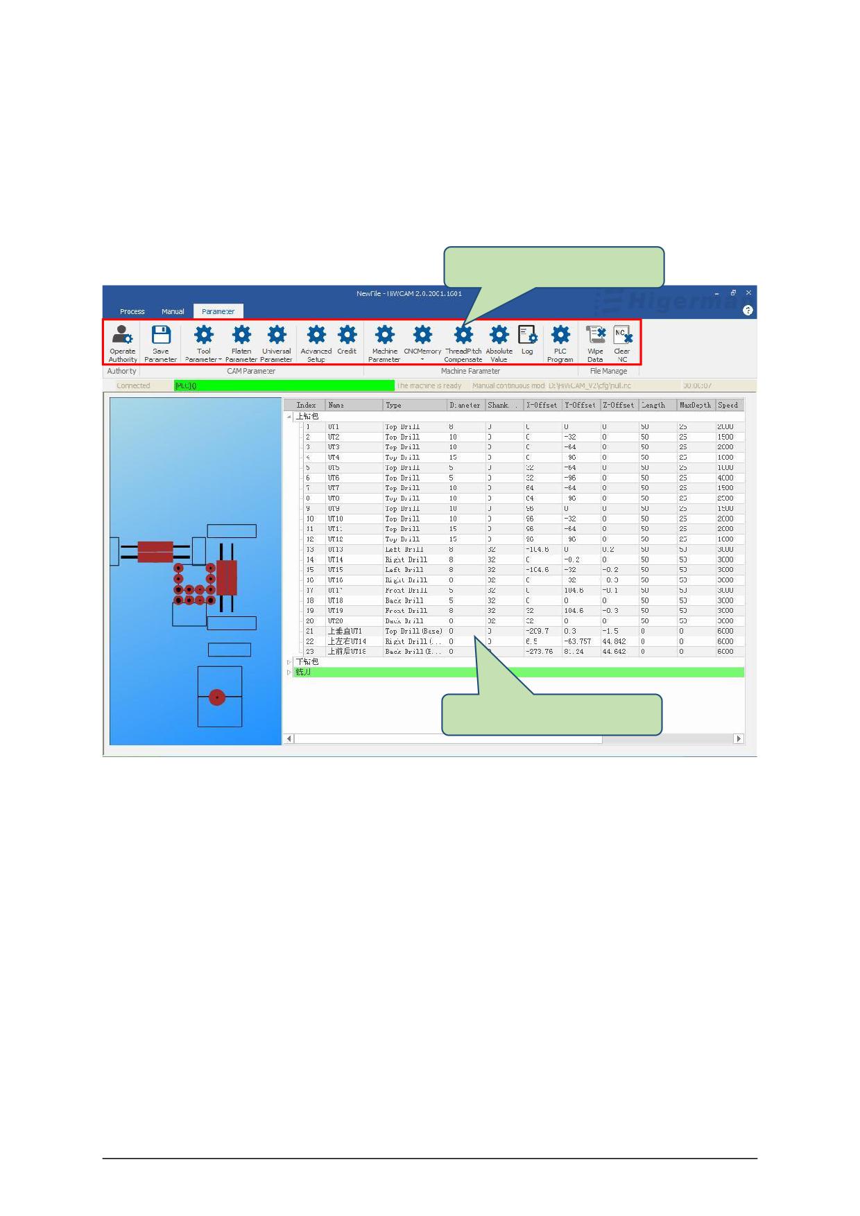
5.parameter
Display all tool parameters and modifiable parameters.
Parameter interface menu
Parameter display area
- 38 -
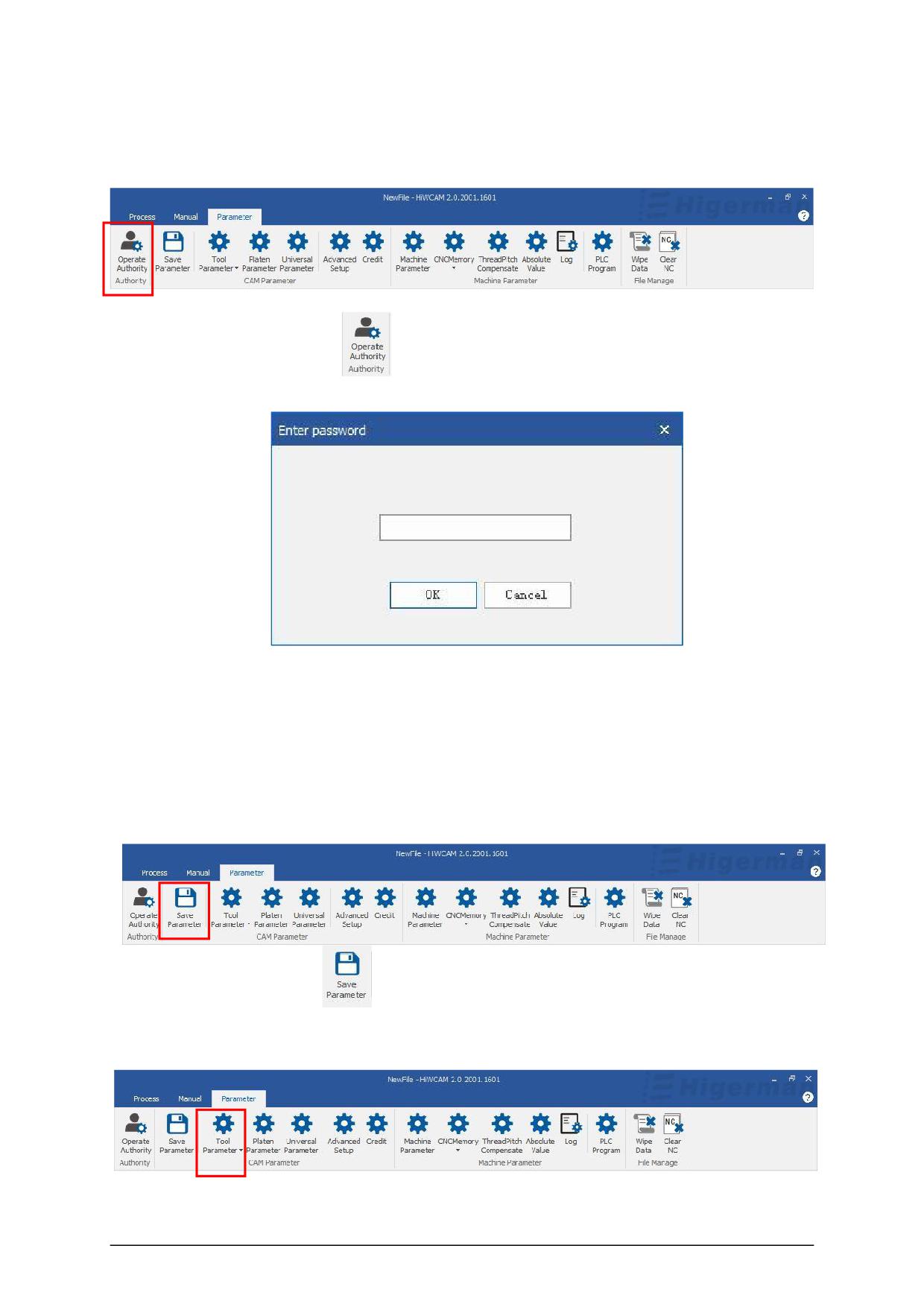
5.1 Operation authority
Click "Operation Authority"
and a dialog box for entering the password will pop up .
Enter the password: Level 1 password hi001, you can enter to view tool parameters and
platen parameters; Level 2 password hi002 , you can operate to open machine parameters
and PLC parameters; Level 3 password hi2003 can open and modify all parameters. Click "OK" to
enter the corresponding level operation, generally our operation is to directly enter hi2003 .
5.2 Save parameters
Click "Save Parameters"
, and the modified parameters will be automatically saved.
5.3 Tool settings
- 39 -
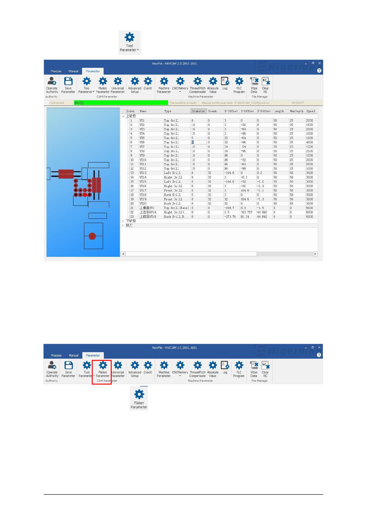
Click "Tool Settings"
, you can see the tool parameters.
If you want to modify the corresponding parameters, double-clicking the parameters does not
respond, you need to click "Operation authority" to enter the level password hi2003 , click OK,
then modify the parameters and click "Save parameters", the setting of the platen parameters and
general parameters is the same.
5.4 Pressure plate parameters
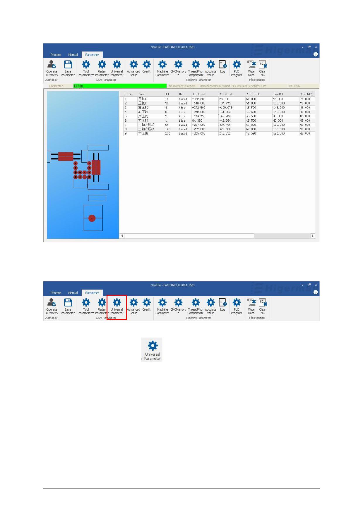
Click "Plate Parameters"
to see the press plate parameters, and you can set and
modify the parameters.
- 40 -
5.5 General/Universal parameters
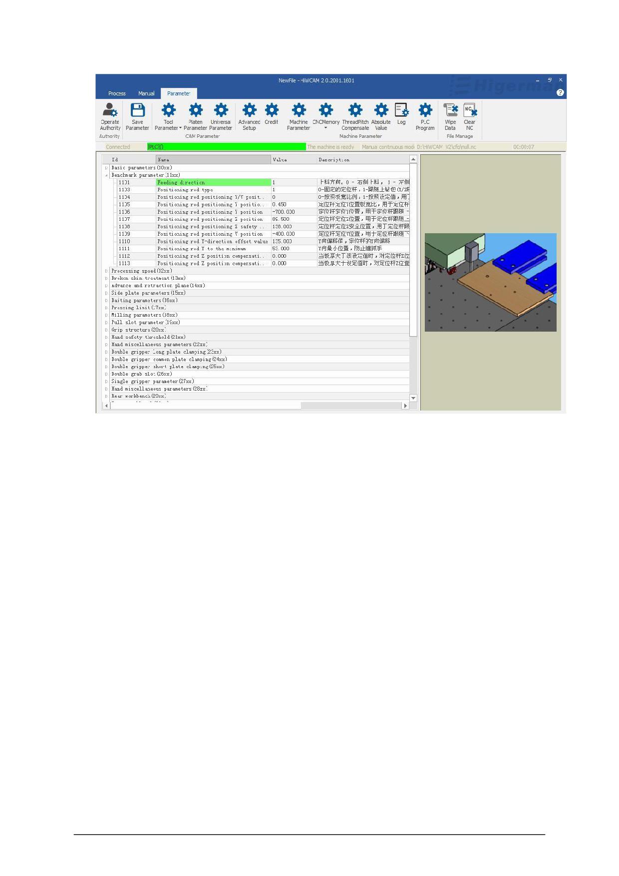
Click "General Parameters"
, you can see the general parameters, you can set and
modify the parameters, and the grouping method is adopted inside.
- 41 -
- 42 -
5.6 Advanced settings
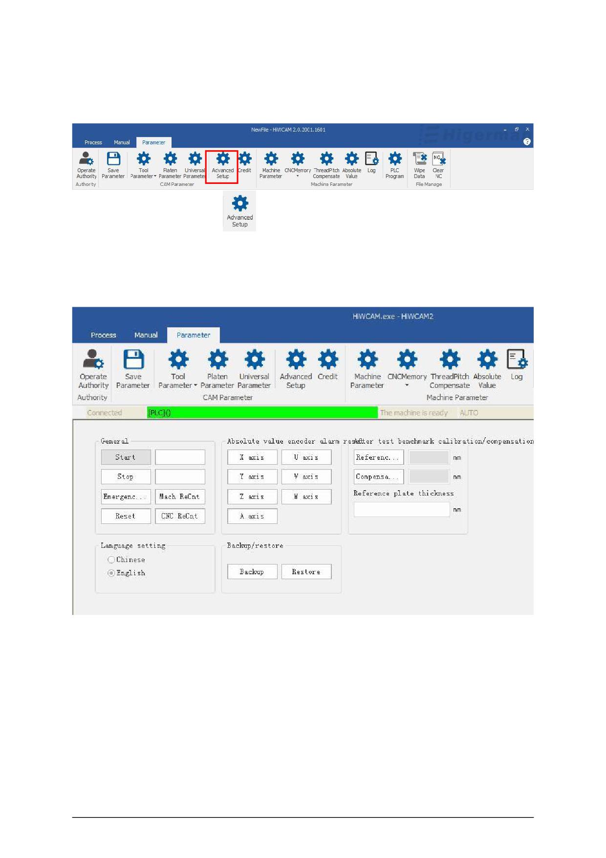
Click "Advanced Settings"
to see the advanced settings interface, you can perform
some operations such as routine start and stop, absolute encoder alarm reset operations,
thickness measurement reference/ compensation calibration, language settings, backup and
recovery.
- 43 -
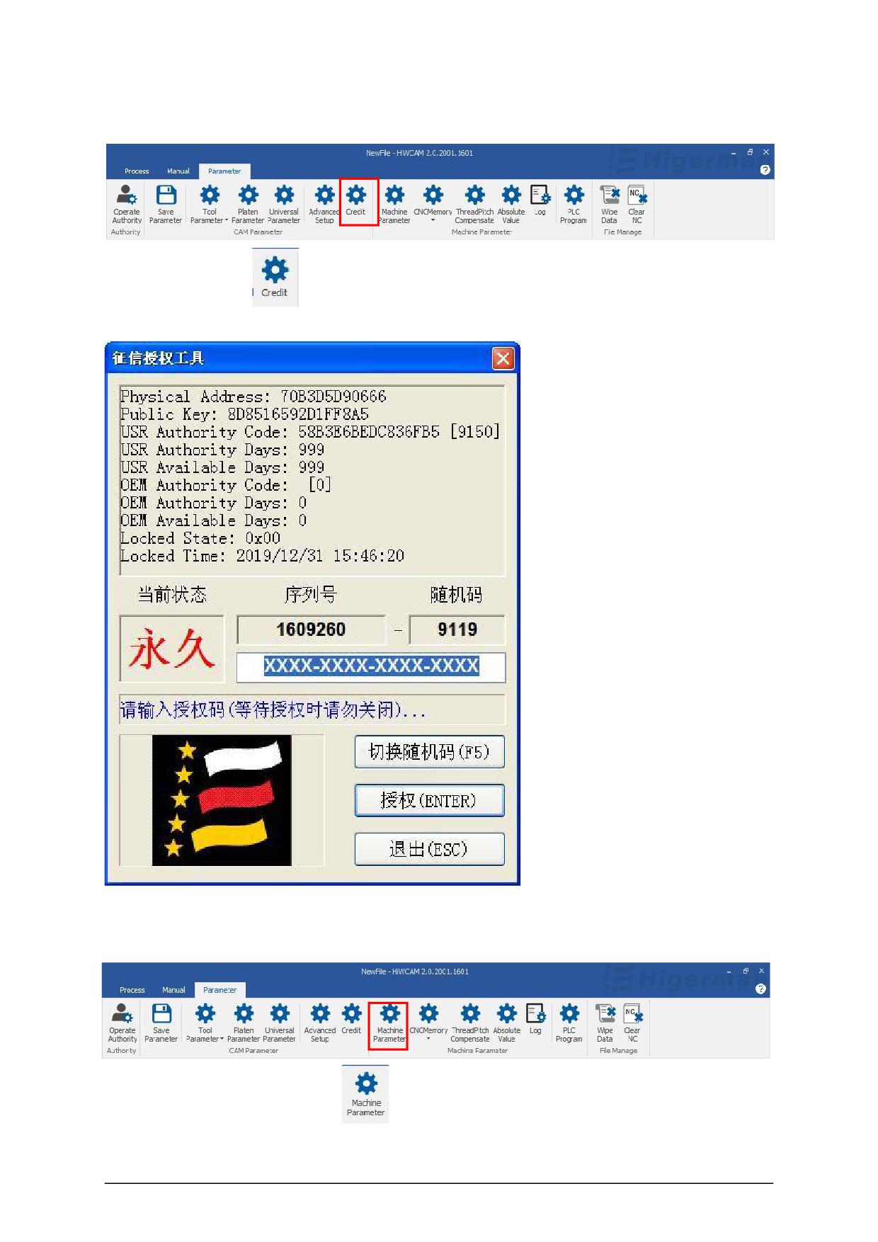
5.7 Credit Investigation Authorization
Click "Credit "
to open the credit investigation authorization, and you can set the
system credit investigation time through the authorization code.
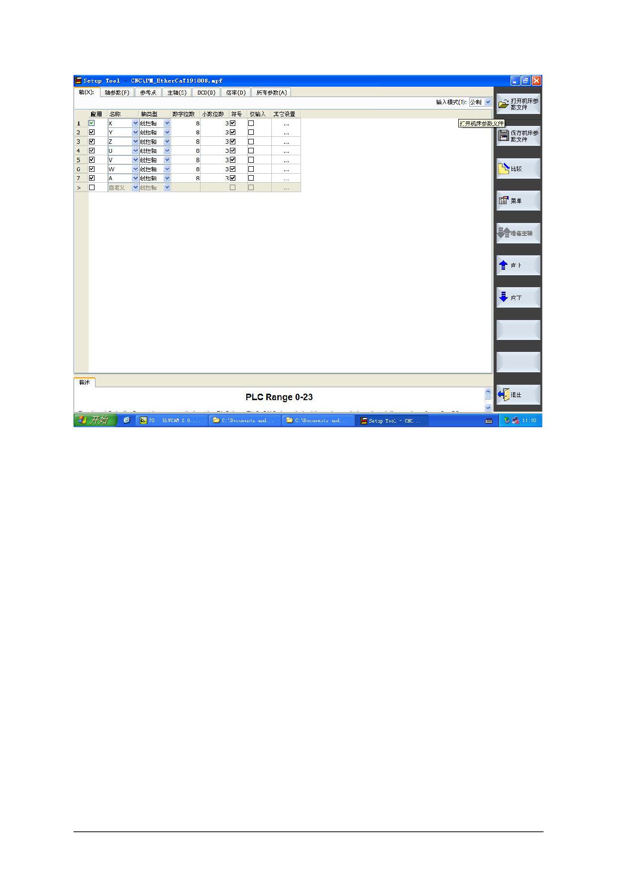
5.8 Machine parameters
Click "Machine Parameters"
to jump to this page where you can set and modify
machine parameters.
- 44 -
- 45 -
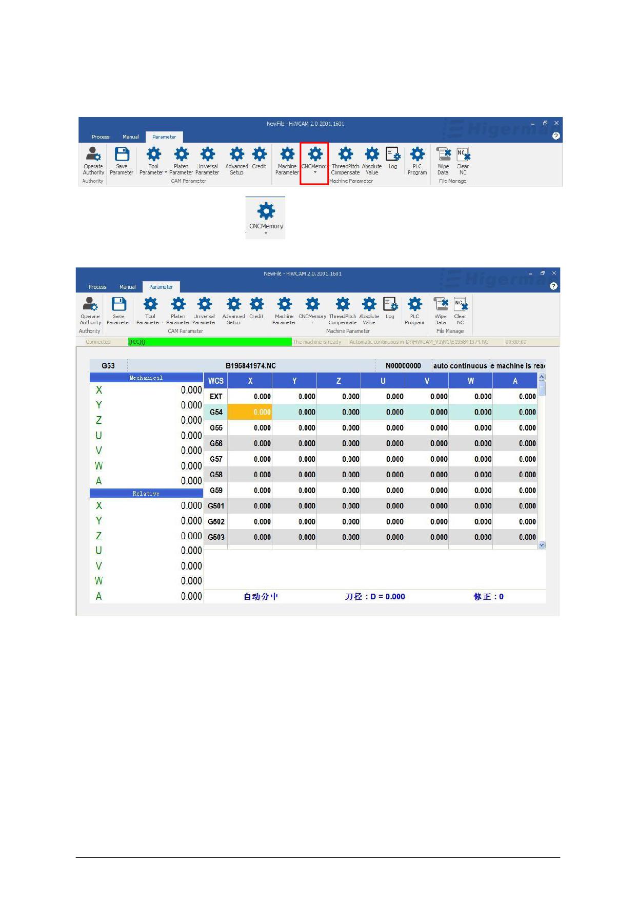
5.9 HMI/CNC Memory
Click "CNC Memory "
, it will jump to this page, you can set and
modify P parameters.
- 46 -
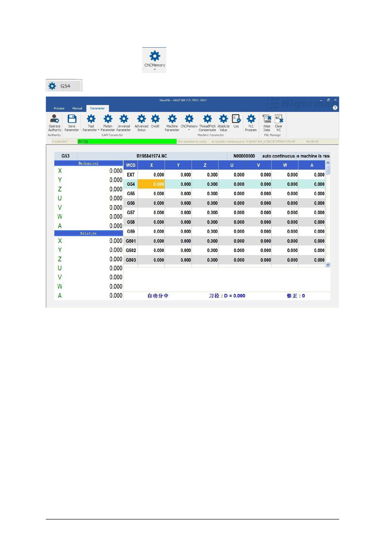
Click "CNC Memory "
, drop-down box button, select " G parameter "
, it will jump to this page, you can set and modify G parameters.
- 47 -
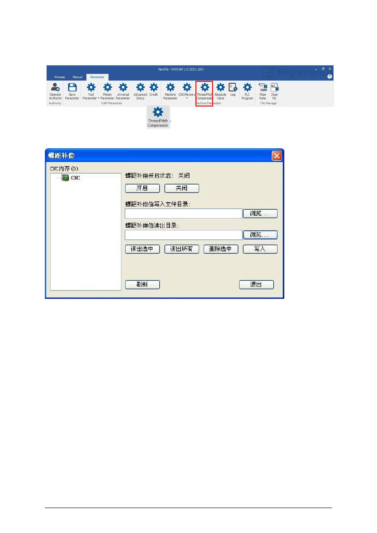
5.10 Pitch compensation
Click "Pitch Compensation"
to pop up this page, you can turn on the pitch
compensation, write and read the catalog.
- 48 -
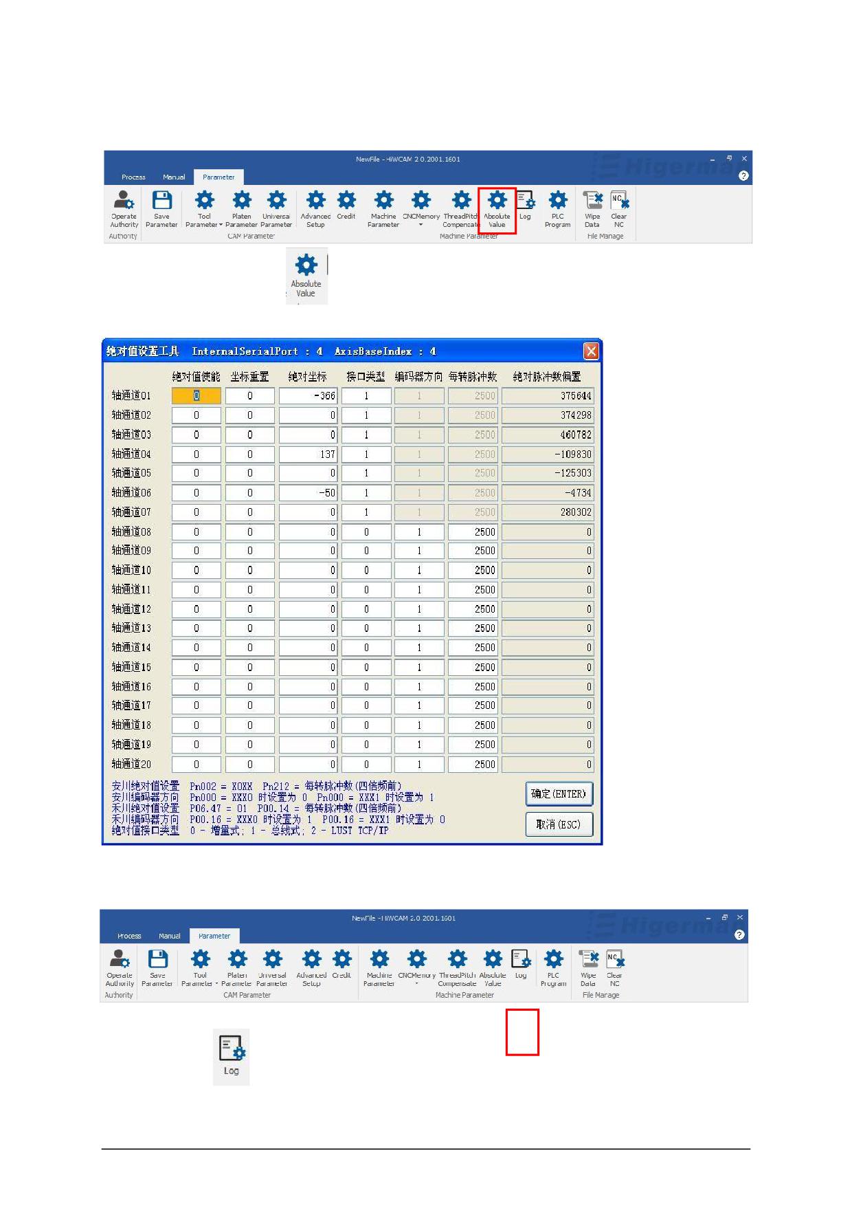
5.11 Absolute value
Click "absolute value"
to pop up this interface, you can set the absolute value, click
"absolute value".
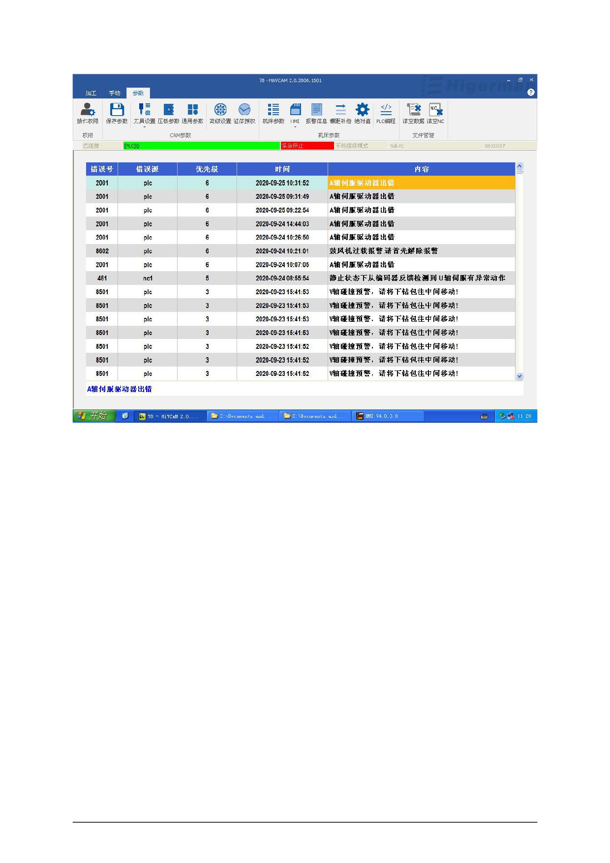
5.12 Alarm information/Log
Click "Log"
to query the alarm error information.
- 49 -
- 50 -
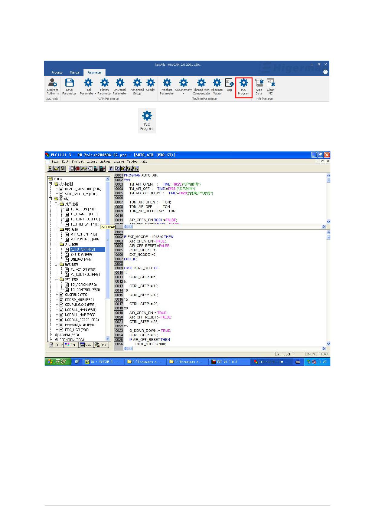
5.13 PLC programming
Click "PLC Programming"
, this interface pops up, you can open and load PLC , note
(loading PLC needs to reopen HICAME ).
- 51 -
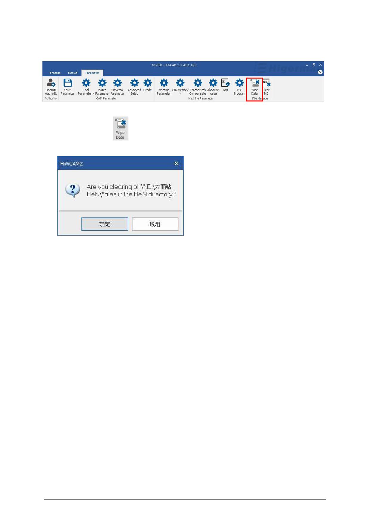
5.14 Clear data
Click "Clear Data"
Click "Yes" to quickly delete files in the data directory. Please pay attention when deleting.
- 52 -
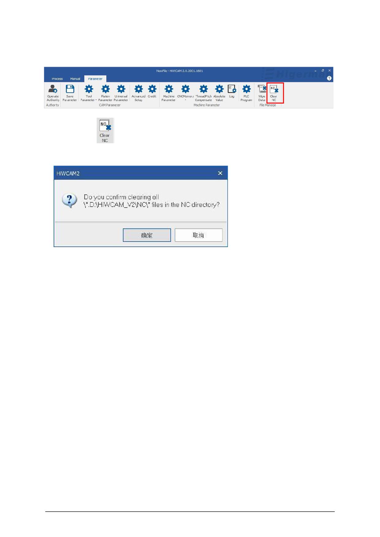
5.15 Clear NC
Click "Clear NC "
, a dialog box will pop up to confirm the deletion of the directory.
Click "Yes" to quickly delete the files in the data directory NC , please note when deleting.
- 53 -
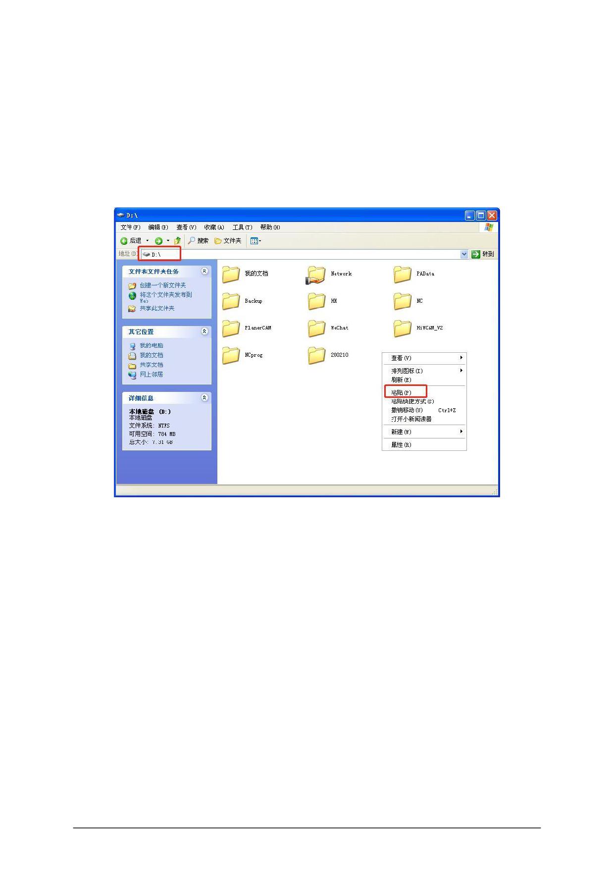
Attachment 1: Instructions for
updating six-sided boring machine CAM
1. Exit the software before updating.
2. Copy the bin compressed file needed for the update and paste it into the system D drive.
3. Decompress the bin compressed file required for the update , choose to unzip it to the
current folder, and unzip it to a bin folder.
- 54 -
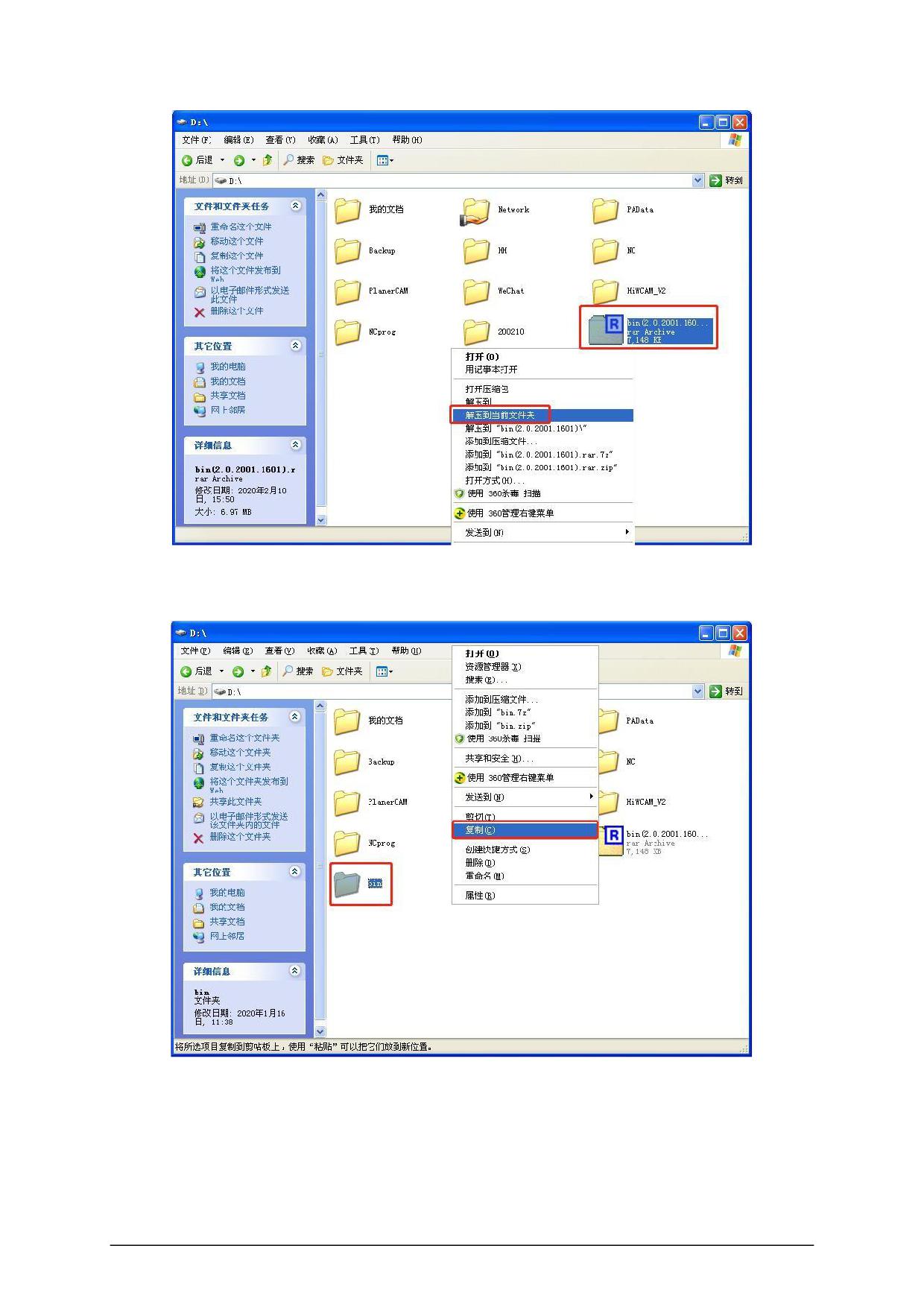
4. Copy and paste the decompressed entire bin folder into the D:\HiWCAM_V2 path,
and overwrite the original bin folder directly.
- 55 -
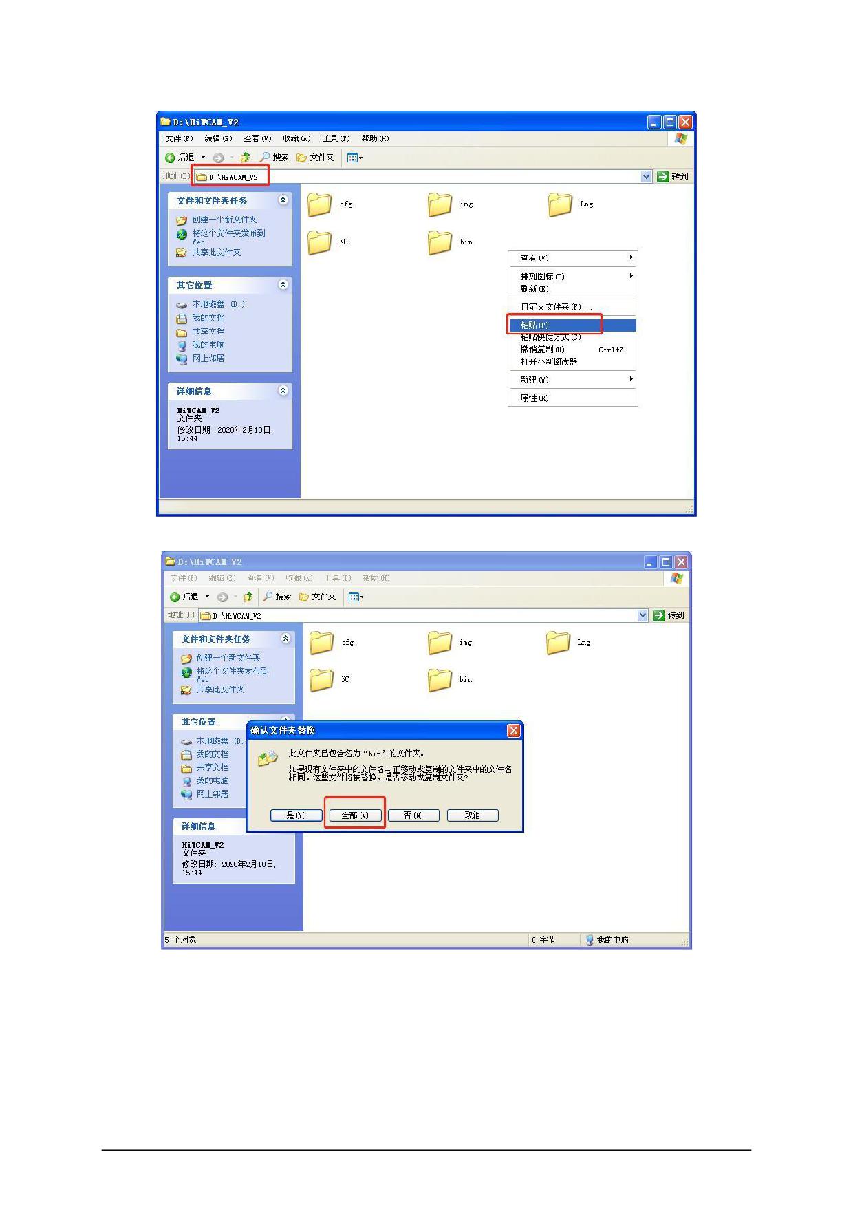
5. After the replacement is successful, the update is completed.
- 56 -
Appendix 2: Servo alarm code
List of alarm codes
Alarm code
name
Stop method
Can reset
alarm
record
System
parameter
Not
Err.001
Stop now
No record
abnormal
resettable
Product model selection
Not
Err.002
Stop now
No record
failure
resettable
Not
Err.003
Fault in parameter storage
Stop now
No record
resettable
Not
Err.004
FPGA failure
Stop now
No record
resettable
Not
Err.005
Product matching failure
Stop now
No record
resettable
Not
Err.006
Program exception
Stop now
No record
resettable
Incremental
Not
Err.007
encoder UVW data is
Stop now
Store records
resettable
abnormal
Short-to-ground
detection
Not
Err.008
Stop now
Store records
fault
resettable
Not
Err.009
Overcurrent fault A
Stop now
Store records
resettable
Err.010
Overcurrent fault B
Stop now
Store records
Resettable
Incremental
photoelectric
encoder Z is disconnected
Err.012
or the number of turns of
Stop now
Store records
Resettable
absolute
encoder
is
abnormal
Encoder
communication
Err.013
Stop now
Store records
Resettable
abnormal
- 57 -
Err.014
Encoder data is abnormal
Stop now
Store records
Resettable
Encoder battery voltage is
Not
Err.015
Stop now
Store records
too low abnormal
resettable
Speed
deviation is too
Err.016
Can be set
Store records
Resettable
large
Err.017
Torque saturation timeout
Can be set
Store records
Resettable
Err.020
Overvoltage
Stop now
Store records
Resettable
Decelerate to
Not stored by
Err.021
Undervoltage
Resettable
stop
default, optional
Err.022
Current sampling failure
Stop now
Store records
Resettable
AI sampling voltage is too
Err.023
Stop now
Store records
Resettable
large
Err.024
Overspeed
Stop now
Store records
Resettable
Err.025
Electric angle recognition
Stop now
No record
Resettable
failed
Err.026
Inertia identification failure
Stop now
No record
Resettable
failure
Err.027
DI
terminal
parameter
Stop now
No record
Resettable
setting failure
Err.028
DO
terminal
parameter
Stop now
No record
Resettable
setting failure
Err.040
Servo ON command invalid
Can be set
No record
Resettable
fault
Frequency division pulse
Err.042
Can be set
Store records
Resettable
output overspeed
Excessive position deviation
Err.043
Can be set
Store records
Resettable
fault
Err.044
Main circuit input phase loss
Can be set
Store records
Resettable
Err.045
Driver output phase loss
Can be set
Store records
Resettable
Err.046
Drive overload
Can be set
Store records
Resettable
Err.047
Motor overload
Can be set
Store records
Resettable
- 58 -
Err.048
Electronic gear setting error
Can be set
No record
Resettable
Err.049
Radiator overheated
Can be set
Store records
Resettable
Err.050
Pulse input abnormal
Can be set
Store records
Resettable
Err.051
Full closed loop position
Can be set
Store records
Resettable
deviation is too large
Err.054
User forced fault
Can be set
Store records
Resettable
Err.055
Absolute position reset fault
Can be set
Store records
Resettable
Err.056
Mains power failure
Decelerate to
Not stored by
Resettable
stop
default, optional
Err.060
The first time after writing a
Stop now
No record
Not
customized version of the
resettable
program
start up
AL.080
Undervoltage warning
non-stop
No record
Resettable
AL.081
Drive overload warning
non-stop
Store records
Resettable
AL.082
Motor overload warning
non-stop
Store records
Resettable
AL.083
Parameter changes that
non-stop
No record
Resettable
need to be turned on again
AL.084
Servo is not ready
non-stop
No record
Resettable
AL.085
Frequent operation warning
non-stop
No record
Resettable
when writing E2PROM
AL.086
Forward overtravel warning
non-stop
No record
Resettable
prompt
AL.087
Negative overtravel warning
non-stop
No record
Resettable
prompt
AL.088
Position
command
non-stop
No record
Resettable
overspeed
AL.090
Absolute encoder angle
non-stop
Store records
Resettable
initialization warning
AL.093
Dynamic braking overload
non-stop
Store records
Resettable
AL.094
External
regenerative
non-stop
No record
Resettable
- 59 -
bleeder resistance is too
small
AL.095
emergency stop
stop
No record
Resettable
AL.096
Return to origin error
Decelerate to
No record
Resettable
stop
AL.097
Encoder
battery
non-stop
No record
Resettable
undervoltage
- 60 -
Alarm reason and treatment measures
Alarm code and name
the reason
Treatment measures
1. The control power supply
1. Ensure that the power
voltage drops instantly;
supply voltage is within the
specification range and restore
2. After upgrading the driver
Err.001 :
software, the range of some
factory parameters ( P20.06
is set to 1 );
parameters
has
been
System parameter abnormal
changed,
causing
the
2. If the software is upgraded,
previously
stored
please restore the factory
parameters to exceed the
parameters first .
upper and lower limits .
1. The encoder cable is
1. Check whether the encoder
damaged or the connection
wiring is normal and make sure
Err.002 :
is loose;
the wiring is firm;
Product model selection failure
2. Invalid motor model or
2. Replace with a valid motor
driver model .
model or drive model .
1. The upper device uses
communication to modify the
parameters and write
1. Parameter reading and
EEPROM operation is too
writing are too frequent;
frequent
,
please
check
whether there is an instruction
2. The parameter storage
to
frequently
modify
Err.003 :
device fails;
parameters
and
write
Fault in parameter storage
to
EEPROM
in
3. The control power supply
the communication program ;
is unstable;
2. Check the control electrical
4. The drive is faulty .
wiring and at the same time
ensure that the control power
supply voltage is within the
specification range .
Err.004 :
The software version is
Check whether the software
abnormal .
version number is normal .
FPGA failure
1. The encoder cable is
1. Check whether the encoder
Err.005 :
damaged or the connection
wiring is good;
Product matching failure
is loose;
2. Replace products that do not
- 61 -
2.
Use
unsupported
match;
external interfaces such as
3. Select the correct encoder
encoders, etc.;
type or replace other types of
3. The power of the motor
drivers; for example, the power
model and the drive model
level of the set motor model is
does not match;
greater than the power level of
the drive, or the power level of
4. Product model code that
the set motor model is two
does not exist .
levels worse than the power
level of the drive, it will be
reported This malfunction .
1.
Abnormal
system
EEPROM
failure,
restore
Err.006 :
parameters;
factory parameters ( P20.06
Program exception
2. Internal failure of the
Set to 1 ), power on again .
drive .
Err.007 :
Encoder signal abnormality
Check the encoder wiring or
Incremental
was detected at power-on .
replace the encoder cable .
encoder is UVW data abnormality
1.
Check
whether
the
cable
UVW
is
short-circuited to ground, if so,
1 , UVW wiring error;
replace the cable;
Err.008
:
Short-to-ground
2. The motor is damaged;
2. Check whether the motor
detection fault
wire resistance and ground
3. The drive is faulty .
resistance are normal, and
replace the motor if it is
abnormal .
- 62 -
1. Check the sequence of command
input, the servo is turned on "rdy"
Then enter the instruction;
2. Measure whether the resistance of
the braking resistor meets the
specifications, and select a reasonable
braking resistor according to the
1.
The
command
input
is
requirements of the manual;
synchronized with the servo on or
the command input is too fast;
3. Check whether the cable connector
is loose and make sure the connector
2. The external braking resistor is
is tight;
too small or short-circuited;
Err.009 :
4. Check the insulation resistance
3. Poor contact of the motor cable;
between the motor's UVW wire and
Overcurrent
4. The motor cable is grounded;
the motor grounding wire. Replace the
fault A
motor when the insulation is poor;
5. Short circuit of motor UVW cable;
5. Check whether the motor cable
6. The motor burns out;
connection UVW is short-circuited,
and connect the motor cable correctly;
7.
The software detects the
overcurrent of the power transistor .
6. Check whether the resistance value
of each cable of the motor is the same,
if it is different, replace the motor;
7. Reduce the load. Increase drive and
motor capacity,
Extend
the
acceleration
and
deceleration time .
- 63 -
1. Check the sequence of command
input, the servo is turned on "rdy"
Then enter the instruction;
2. Measure whether the resistance of
the braking resistor meets the
specifications, and select a reasonable
braking resistor according to the
requirements of the manual;
1.
The
command
input
is
synchronized with the servo on or
3. Check whether the cable connector
the command input is too fast
is loose and make sure the connector
is tight;
2. The external braking resistor is
too small or short-circuited
4. Check the insulation resistance
Err.010 :
between the motor's UVW wire and
3. Poor contact of the motor cable
Overcurrent
the motor grounding wire. Replace the
4. Ground the motor cable
fault B
motor when the insulation is poor;
5. Short circuit of motor UVW cable
5.
Check if the motor cable
connection UVW is short-circuited,
6. The motor burns out;
Connect the motor cable correctly;
7.
The software detects the
overcurrent of the power transistor .
6. Check whether the resistance
between the cables of the motor is
phase-to-phase
Same, but different, replace the motor;
7. Reduce the load. Increase the
capacity of the drive and motor, and
extend
the
acceleration
and
deceleration time .
Incremental encoder:
1. Manually rotate the motor shaft, if it
Err.012 :
still reports a fault,
1
,
Z signal
reception
Incremental
abnormality, Z and signal wiring
Then check the encoder wiring, re-wire
photoelectric
failure
causes
poor
or
an
or replace the cable, or replace the
encoder
Z
encoder Z signal loss;
encoder, and re-power on;
is disconnected
or the number
Absolute encoder:
2. It is necessary to determine whether
of
turns
of
the battery is normal , if the battery
2. Absolute encoder battery power
absolute
voltage
supply is insufficient;
encoder
is
Insufficient, please replace the battery;
abnormal
3. Parameter P06.47=1 ( set to
absolute system ) , the encoder
3. Set P20.06=7 to initialize the
- 64 -
initialization operation is not carried
number of turns and power on again;
out;
4. Set P20.06=7 to initialize the
4. When the drive is powered off,
number of turns, and power on again .
the encoder motor terminal wiring is
unplugged .
1.
The
serial
encoder
is
Err.014 :
disconnected or has poor contact;
Check the wiring or replace the
Encoder data is
2. The reading and writing of data
encoder cable .
abnormal
stored in the serial encoder is
abnormal .
Err.015 :
The encoder battery voltage is
lower than the threshold set
Encoder battery
Replace the encoder battery .
by P06.48 , and the tens place
voltage is too
of P06.47 is set to 1 .
low
1 , the P06.45 set value increased;
2.
Extend the acceleration and
deceleration time of the internal
Err.016 :
The absolute difference between
position command,
the speed command and the actual
Speed
Or adjust the gain to improve the
measured speed exceeds the
deviation is
response of the system;
threshold set by P06.45 .
too large
3. Disable the function of excessive
speed deviation threshold,
That is, P06.45=0 .
Err.017 :
1. Increase the setting time of
The torque is saturated for a long
parameter P06.46 ;
Torque
time, and the duration exceeds the
saturation
2. Check whether the UVW is
threshold set by P06.46 .
timeout
disconnected .
1. The power supply voltage
1. Input the correct voltage range;
Err.020 :
exceeds
the
allowable
range, AC280V ;
2. Check whether the external resistor
Overvoltage
is connected. Measurement external
2.
The
braking
resistor
is
- 65 -
disconnected and the braking
Whether the resistance of the resistor
resistor is not matched, which
has been disconnected, make sure the
makes it impossible to absorb
wiring is correct
regenerative energy;
Indeed, if the resistor has been
3. The load inertia exceeds the
burned, it is recommended to replace
allowable range;
the
4. The drive is damaged .
External resistance with higher rate
(contact the manufacturer to obtain the
phase
Off recommendations);
3.
Extend the acceleration and
deceleration time, or reselect the
appropriate driver and motor according
to the load inertia .
1. The power supply voltage drops;
1. Increase the power supply voltage
2. Instantaneous power failure
capacity to ensure the stability of the
occurs;
power supply voltage;
Err.021 :
3. The undervoltage protection
2. After confirming that the power
threshold ( P06.36 ) is set too high;
Undervoltage
supply voltage is normal, check the
4. The drive is damaged (Note: This
Whether
the
voltage
protection
fault does not store records by
threshold ( P06.36 ) is set too high .
default, it can be set whether to
store through P07.19 ) .
Err.022 :
The internal current sampling of the
Current
Replace the servo drive .
drive is faulty .
sampling
failure
Err.023 :
1 , AI wiring error;
Connect the AI input correctly and set
AI
sampling
the input voltage to
2. The external input voltage is too
voltage is too
high .
Within ±10V .
large
1. The speed command exceeds
1. Reduce the speed command;
Err.024 :
the maximum speed setting value;
2. Check whether the UVW phase
Overspeed
2 , the UVW phase sequence error;
sequence is correct;
3. The speed response is seriously
3. Adjust the speed loop gain to
- 66 -
overshooting;
reduce overshoot;
4. The drive is faulty .
4. Replace the driver .
Err.025 :
1. Reduce the load or increase the
1. The load or inertia is too large;
Electric angle
current loop gain;
recognition
2. The encoder wiring is wrong .
2. Replace the encoder cable .
failed
1. The load or inertia is too large,
and the motor cannot run
1. Reduce the load or increase the
Err.026 :
according to the specified curve;
current loop gain;
Inertia identification
2. The identification is terminated
2. Ensure that the identification
failure failure
due to other failures during the
process is normal .
identification process .
1 , P04.01 ~ P04.09 have the same
functional configuration
1. Different physical DI terminals
To multiple physical DI terminals;
are repeatedly assigned the
Err.027 :
same DI function;
2
,
P04.01
~ P04.09 assigned
DI
terminal
function,
2. The physical DI terminal and
parameter
setting
and P09.05 ~ P09.08 corresponding
the DI function of communication
failure
bits simultaneously
control are allocated at the same
time .
To
enable,
please
refer
to
the usage of P09.05 ~ P09.08
;
redistribute DI functions .
P
a
D
04O
of
.21
~
Err.028 :
a P case 04 case .2 , 9 heavy fraction
Different DOs are assigned the
DO
terminal
with
a
new
distribution
same output repeatedly .
parameter
setting
function DO can be set to function with
failure
multiple energy .
After executing the auxiliary
Err.040 :
function of energizing the motor,
Change improper operation method .
Servo ON command
the servo ON command is still
invalid fault
input from the host computer .
Change the function code of the
Err.042 :
The upper limit of pulse output
frequency division output setting so
allowed
by
hardware
is
that the
Frequency division
exceeded .
pulse
output
Frequency division output pulse in the
- 67 -
overspeed
whole speed range of work
The frequency will not exceed the
limit .
1. Confirm the wiring of the main
circuit cable of the motor and re
wiring;
2. Confirm whether the gain of the
servo drive is too low.
1. UVW wiring of the servo
High gain
motor ;
3. Try to reduce the instruction
2. The servo driver gain is low;
frequency before running the lower
position
3. The frequency of position
command pulse is relatively high;
Set command frequency, command
acceleration or adjust electronic gear
4.
The
position
command
acceleration is too large;
Wheel ratio
Err.043 :
5. The position deviation exceeds
4. Reduce the command acceleration
the fault value of excessive
Excessive position
before running to join the position
deviation fault
position
deviation
(P00.19).
The set value is too small;
Smooth functions such as command
acceleration and deceleration time
6. Servo drive / motor failure;
parameters;
7.
The
brake
is
released
5 , confirm the value of the position
abnormally, the motor is blocked
deviation fault (P00.19) is appropriate,
or driven by external forces, such
correctly set (P00.19 ) value;
as mechanical jamming, collision,
dragging by gravity or other
6. Check the running graphics in the
external forces.
backg8round. If there is no feedback,
please replace the servo driver ;
7. Check wiring and brake power
supply, confirm whether the brake is
normal, and confirm that the motor is
not blocked or driven by external
force.
1. Check whether the three-phase
1. The three-phase input cable is
Err.044 :
power input cable is connected
in poor contact;
Main circuit input
Stable (pay attention to safety, do not
2 , phase fault , i.e., the main
phase loss
operate with electricity);
power ON state , R \ S \ T a
- 68 -
phase voltage phase of the low
2. Measure the voltage of each phase
state continues for 1 sec or more .
of the three-phase power supply to
ensure the output
Input power three-phase balance or
ensure input power voltage
Meet the specifications .
Err.045 :
1. The motor UVW wiring is bad;
1. Check the UVW wiring;
Driver
output
2. The motor is damaged and there
2. Replace the servo motor .
phase loss
is an open circuit .
The load operation exceeds the
inverse time curve of the drive for
the following reasons:
1. Confirm whether there is a problem
1. The motor UVW wire or encoder
with the wiring of the motor UVW line
wire is bad or the connection is
and the encoder;
loose;
2. Confirm that the motor is not
2. The motor is blocked or driven by
blocked or driven by external force,
external forces, such as mechanical
and confirm that the mechanical brake
jamming, collision, dragging by
(brake) has been opened;
gravity or other external forces, or
the mechanical brake (brake) is
3. Confirm that there is no cross wiring
running without opening;
of multiple drives and motors, that is,
Err.046 :
there is no UVW line and encoder line
3. When wiring multiple drives,
Drive overload
of a motor connected to different
mistakenly connect others to the
drives;
same
4.
Extend the acceleration and
The UVW line of the motor and the
deceleration time, and re-select the
encoder line are connected to
appropriate driver or motor;
different drives;
5. Check whether the UVW output by
4. The load is too large, and the
the motor is connected wrongly or
driver or motor selection is too
short-circuited to the ground;
small;
6. Replace the driver or motor .
5. There may be missing phase or
wrong phase sequence connection;
6. The driver or motor is damaged .
The load running exceeds the
Err.047 :
1. Confirm whether the wiring of
inverse time curve of the drive for
- 69 -
Motor overload
the following reasons:
the motor UVW line and the encoder
1. The motor UVW wire or encoder
There is a problem
wire is bad or the connection is
2. Confirm that the motor is not
loose;
blocked or driven by external force,
2. The motor is blocked or driven by
confirm
external force, such as machinery
Confirm that the mechanical brake
Stuck, collision, drag by gravity or
(holding brake) has been opened;
other external forces, or the
3. Confirm that multiple drives and
mechanical brake (brake) is running
motors do not cross
without opening ;
Wiring, that is, there is no connection
3. When wiring multiple drives,
between the UVW wire and encoder
mistakenly connect others to the
wire of a motor to different drives;
same
4.
Extend the acceleration and
The UVW line of the motor and the
deceleration time and reselect the
encoder line are connected to
appropriate driver or motor;
different drives;
5. Check whether the UVW output by
4. The load is too large, and the
the motor is connected wrongly, yes
driver or motor selection is too
small;
No short circuit to ground;
5. There may be missing phase or
6. Replace the driver or motor .
wrong phase sequence connection;
6. The driver or motor is damaged .
Err.048 :
The electronic gear ratio exceeds
the specification
Set the correct gear ratio range .
Electronic gear
range [0.001,4000] .
setting error error
1. Whether the fan is running
1. The fan is damaged;
during operation, replace the fan
Err.049 :
2. The ambient temperature is too high;
or drive
Radiator
3. Reset the overload fault by turning off the
Actuator
overheated
power after overload, and continue for many
times;
2.
Measure
the
ambient
temperature to improve the
- 70 -
4. The installation direction of the servo drive
cooling of the servo drive
and other servos
Cooling conditions, lower the
Unreasonable interval between service drives;
ambient temperature;
5. Servo drive failure;
3. Check the fault record,
whether there is an overload
6. The driver or motor is damaged .
fault reported,
Change the fault reset method,
wait 30s after overload
Reset again. The selected power
of the driver and motor is too
small, increase the capacity of
the driver and motor, increase
the
acceleration
and
deceleration time, and reduce
the load;
4. Confirm the setting status of
the servo drive,
Install
the
service
driver
according to
the installation
standard;
5. Whether the fault is still
reported
after
5
minutes
of power failure,
If the fault is still reported after
restarting, please replace the
servo drive .
1.
Change
the
maximum
allowable
frequency,
parameter P06.38 ;
2. The backg8round software
Err.050 :
1. The input frequency is greater than the
checks whether the instruction is
pulse input maximum frequency setting value;
abnormal and checks the line
Pulse
input
abnormal
2. The input pulse is disturbed .
Circuit grounding, to ensure that
the circuit is grounded reliably,
and the signal
Use twisted-pair shielded wire,
separate input wire and power
- 71 -
wire
Wiring .
1. Confirm whether the external
encoder cable is connected
correctly, and change
Change the external encoder;
Err.051 : Full
closed loop
1. The external encoder is abnormal;
2. The deviation of the fully
position
closed loop is too large, and the
deviation
is
2. The relevant settings are too conservative .
protection
function
is
set
too large
incorrectly
Confirm the settings of the
relevant parameters and reset
the relevant parameters .
Normal
DI
function
Err.054 :
input,
DI
function
32
Forced
to
enter
the
fault
is configured and the input is
User forced
state through DI function 32 ( FORCE_ERR ) .
valid. Disconnect the input to
fault
clear the fault .
Err.055 :
Absolute
Absolute position encoder absolute position
Contact the manufacturer for
position reset
reset failure .
technical support .
fault
Power failure or abnormal main power
Err.056 : The
Check whether the input main
line. (Note: this reason
main power
power supply has instantaneous
supply is cut
power failure and increase the
By default, the record is not stored, and you
off
power supply voltage capacity .
can set whether to store it through P07.19 ) .
Err.060 :
First
start
It is the first time to start after downloading the
Restore factory values
to
after writing a
customized version of the driver that has the
load custom parameters .
customized
standard program .
version of the
program
1. Check whether the input
AL.080 :
The warning status is output when the bus
main power supply is normal ;
Undervoltage
voltage is low .
warning
2.
Lower
the undervoltage detection point
- 72 -
parameter P06.36 .
The load operation exceeds
the inverse time curve of the
1. Confirm whether the wiring of
drive
for
the
following
the motor UVW line and the encoder
reasons:
There is a problem
1. The motor UVW wire or
encoder wire is bad or the
2. Confirm that the motor is not
connection is loose;
blocked or driven by external force,
2. The motor is blocked or
Confirm that the mechanical brake
driven by external forces,
(holding brake) has been opened;
such as mechanical jamming,
3. Confirm that there is no crossover
collision, dragging by gravity
between multiple drives and motors.
or other external forces, or
the mechanical brake (brake)
Cross wiring, that is, there is
AL.081 :
runs without opening ;
no UVW wire of a motor
Drive overload warning
3.
When wiring multiple
Connect the encoder cable to a
drives, mistakenly connect
different drive;
the UVW wires and encoder
wires of the same motor to
4. Extend the acceleration and
different drives;
deceleration time and reselect the
appropriate one
4. The load is too large, and
the driver or motor selection
Drive or motor;
is too small;
5. Check whether the UVW output by
5. There may be missing
the motor is connected wrongly, yes
phase
or
wrong
phase
No short circuit to ground;
sequence connection;
6. Replace the driver or motor .
6. The driver or motor is
damaged .
1. Confirm whether the wiring of
The load operation exceeds
the inverse time curve of the
the motor UVW line and the encoder
drive
for
the
following
There is a problem
reasons:
AL.082 :
2. Confirm that the motor is not
1. The motor UVW wire or
Motor overload warning
blocked or driven by external force,
encoder wire is bad or the
connection is loose;
Confirm that the mechanical brake
(holding brake) has been opened;
2. The motor is blocked or
driven by external forces,
3. Confirm that there is no crossover
- 73 -
such as mechanical jamming,
between multiple drives and motors.
collision, dragging by gravity
Fork wiring, that is, there is
or other external forces, or
no connection between the UVW wire
the mechanical brake (brake)
and encoder wire of a motor to
runs without opening;
different drives;
3.
When wiring multiple
4. Extend the acceleration and
drives, mistakenly connect
deceleration time and reselect the
the UVW wires and encoder
appropriate drive
wires of the same motor to
different drives;
Actuator or motor;
4. The load is too large, and
5. Check whether the UVW output by
the driver or motor selection
the motor is connected wrongly, yes
is too small;
No short circuit to ground;
5. There may be missing
phase
or
wrong
phase
6. Replace the driver or motor .
sequence connection;
6. The driver or motor is
damaged .
AL.083 :
The parameters that need to
Parameter changes that
be turned on again to take
Power on again .
need to be turned on
effect are changed .
again
AL.084 :
It
will
be
enabled
when
Servo Servo not ready ON .
the servo READY is detected .
Servo is not ready
L.085 :
Reduction E an EPROM write -in
The
program
operation frequency , can not be
Write E2PROM frequenc
operates E2PROM abnormall
stored
y
y frequently .
instead EEPROM communication writ
Operation warning
e instruction .
1
,
Pot
and
Not
while
The positive limit switch is triggered,
AL.086 :
effective , generally do not appear
check the operating mode,
in the table at the same time;
Forward
Give a negative command or manually
overtravel
2. The overtravel state of the servo
rotate the motor to leave the positive
warning prompt
axis in a certain direction can be
direction
automatically released .
The limit will automatically clear the
- 74 -
warning .
The negative limit switch is triggered to
1
,
Pot
and
Not
while
check the operating mode,
AL.087 :
effective , generally do not appear
Give a positive command or manually
in the table at the same time;
Negative
rotate the motor to leave the negative
overtravel
2. The overtravel state of the servo
direction
warning prompt
axis in a certain direction can be
The limit will automatically clear the
automatically released .
warning .
AL.088 :
1. The electronic gear ratio is set
1. Reduce the set electronic gear ratio;
too large;
Position
command
2. Reduce the input pulse frequency .
2. The pulse frequency is too high .
overspeed
AL.090 :
When the encoder angle is
Absolute
reinitialized, the deviation is too
Replace the motor .
encoder angle
large ( more than 7.2 degrees in
initialization
electrical angle ) warning .
warning
Energy consumption braking power
overload
1. Wrong wiring or poor contact of
braking resistor;
1. Check whether the wiring of the
braking resistor is normal;
2. When using built-in resistors, the
default short wiring may fall off;
2. Check whether the built-in resistance
wiring is normal;
3. The braking resistor capacity is
AL.093 :
insufficient;
3. Increase the braking resistor capacity;
Dynamic
4. Excessive resistance of the
4. Reduce the resistance of the braking
braking
braking resistor leads to long-term
resistor;
overload
braking
5. Reduce the input voltage value;
move;
6. Set appropriate parameters according
5. The input voltage exceeds the
to specifications;
regulations;
7. Replace the servo driver .
6.
Braking resistor resistance,
capacity, or heating time
Constant setting error;
- 75 -
7. The servo drive is faulty .
1. Configure the power of the external
AL.094 :
regenerative bleeder resistor according
1.
The
external
regenerative
External
to the specifications;
bleeder resistance is less than the
regenerative
minimum required by the driver;
2. Check whether the parameters
bleeder
of P00.21 ~P00.24 are
resistance
is
2. The parameter setting is wrong .
too small
Correct .
Normal
DI
function
AL.095 :
input, configured with DI function 30 and
An emergency stop was triggered .
emergency
the input is valid , disconnect the input
stop
to remove the warning.
1. The time to search the origin
exceeds the set value of P08_95 ;
1 , increase P08.95 set value;
AL.096 :
2
,
P08.90
parameter is set
2. The search speed of returning to the
to 3 , 4 or 5 , and against the
Return to origin
origin is too fast, so reduce the speed of
stopper;
error
returning
to
the
origin
search P08.92 and P08.93 .
3. When the limit is not the origin,
the limit is encountered twice
AL.097 :
The encoder battery voltage is
lower than the threshold set
Check and replace the encoder battery .
Encoder battery
by P06.48 .
undervoltage
- 76 -