BB8100 BORING MACHINE. OPERATING MANUAL ORIGINAL INSTRUCTIONS (2023)
BB8100
BORING MACHINE
OPERATING MANUAL
ORIGINAL INSTRUCTIONS
PN: 57064
July 2023
Revision 9
LIMITED WARRANTY
CLIMAX Portable Machine Tools, Inc. (hereafter referred to as “CLIMAX”) warrants that all new
machines are free from defects in materials and workmanship. This warranty is available to the
original purchaser for a period of one year after delivery. If the original purchaser finds any defect
in materials or workmanship within the warranty period, the original purchaser should contact its
factory representative and return the entire machine, shipping prepaid, to the factory. CLIMAX
will, at its option, either repair or replace the defective machine at no charge and will return the
machine with shipping prepaid.
CLIMAX warrants that all parts are free from defects in materials and workmanship, and that all
labor has been performed properly. This warranty is available to the customer purchasing parts or
labor for a period of 90 days after delivery of the part or repaired machine or 180 days on used
machines and components. If the customer purchasing parts or labor finds any defect in materials
or workmanship within the warranty period, the purchaser should contact its factory representative
and return the part or repaired machine, shipping pre- paid, to the factory. CLIMAX will, at its
option, either repair or replace the defective part and/ or correct any defect in the labor performed,
both at no charge, and return the part or repaired machine shipping prepaid.
These warranties do not apply to the following:
• Damage after the date of shipment not caused by defects in materials or workmanship
• Damage caused by improper or inadequate machine maintenance
• Damage caused by unauthorized machine modification or repair
• Damage caused by machine abuse
• Damage caused by using the machine beyond its rated capacity
All other warranties, express or implied, including without limitation the warranties of
merchantability and fitness for a particular purpose are disclaimed and excluded.
Terms of sale
Be sure to review the terms of sale which appear on the reverse side of your invoice. These terms
control and limit your rights with respect to the goods purchased from CLIMAX.
About this manual
CLIMAX provides the contents of this manual in good faith as a guideline to the operator. CLIMAX
cannot guarantee that the information contained in this manual is correct for applications other
than the application described in this manual. Product specifications are subject to change without
notice.
P/N 57064, Rev. 9
Page C
TABLE OF CONTENTS
INTRODUCTION
1
ABOUT THIS MANUAL
1
SAFETY WARNING SYMBOLS
1
GENERAL SAFETY
2
MACHINE SPECIFIC SAFETY PRACTICES
3
RISK ASSESSMENT AND HAZARD MITIGATION
4
RISK ASSESSMENT CHECKLIST
5
INSPECTING THE MACHINE
6
BASIC COMPONENTS
7
OVERVIEW
9
ROTATIONAL DRIVE ASSEMBLY
9
MECHANICAL AXIAL FEED ASSEMBLY
9
HYDRAULIC POWER
10
General description
10
Power unit pendant
10
Hydraulic motor
10
BEARING SUPPORT ASSEMBLIES
11
End-mount self-aligning bearing support assembly (with spider)
11
End-mount self-aligning bearing assembly (without spider)
11
ID-mount non self-aligning bearing support assembly (with spider)
12
Non self-aligning bearing assembly (without spider)
12
CLAMP COLLARS
12
BORING BAR AND LEADSCREW ASSEMBLY
13
AXIAL TOOL CARRIER
13
MANUAL BORING HEAD ASSEMBLY
13
FACING HEAD ASSEMBLY
13
SETUP
15
BORING BAR AND BEARING SUPPORT ASSEMBLY SETUP
15
END-MOUNT BEARING SUPPORT ASSEMBLY SETUP
16
ID-mount bearing support assembly setup
19
ROTATIONAL DRIVE ASSEMBLY SETUP
23
MOUNTING THE AXIAL FEED ASSEMBLY TO THE BAR
24
ATTACHING THE MECHANICAL RAPID FEED (OPTIONAL EQUIPMENT)
25
MOUNTING AN OPTIONAL ELECTRIC AXIAL FEED ASSEMBLY
27
Setting the Axial Feed Rate
28
SETTING THE FEED DIRECTION
28
Setting feed direction while the bar is rotating
28
Setting feed direction when the bar is stopped
28
Disengaging the feed
28
SETTING THE FEED RATE
29
TOOLING SETUP
29
Tool carrier setup
29
To lock the tool carrier on the bar for other operations
30
To remove the brass nut
31
BORING 31
Manual boring head assembly setup
31
P/N 57064, Rev. 9
Page i
Micro Adjustment Boring Head
32
BORING HEAD SETUP
35
FACING HEAD
36
Manual facing head assembly setup
36
Facing head radial feed
37
INSTALLING THE FACING SLIDE ARM ONTO THE TOOL CARRIER
44
Install the slide arm onto the tool carrier
44
Adjusting the tool carrier for perpendicularity
45
Feedbox assembly
45
INSTALL THE COUNTERWEIGHT ARM ONTO THE TOOL CARRIER
45
HYDRAULIC POWER PREPARATION AND CONNECTION
46
OPERATION
47
PRE-START CHECKS
47
Before operating the portable boring bar
47
USING THE REMOTE PENDANTS
48
Feed pendant
48
HPU PENDANT
49
MANUAL OVERRIDE (ELECTRICAL FEED ONLY)
49
CLAMP COLLARS
49
STARTING THE MACHINE
50
STOPPING THE MACHINE
50
REPETITIVE MACHINING
51
DISASSEMBLY
51
Standard disassembly
51
Alternative disassembly
52
MAINTENANCE
53
RECOMMENDED LUBRICANTS
53
BORING BAR/LEADSCREW
53
AXIAL FEED ASSEMBLY
53
ROTATIONAL DRIVE ASSEMBLY
53
BEARING SUPPORT ASSEMBLY
54
TOOL HEAD ASSEMBLY
54
Manual boring head assembly
54
Manual facing head assembly
54
Tool carrier 54
HYDRAULIC POWER UNIT AND MOTOR
54
General hydraulic system
54
Hydraulic motor
54
Hydraulic filter and fluid
54
TROUBLESHOOTING
56
STORAGE
57
SPECIFICATIONS
58
TOOL KIT AND SPARE PARTS
68
EXPLODED VIEWS AND PARTS
71
Page ii
BB8100 Operating Manual
SCHEMATICS
105
SDS
109
P/N 57064, Rev. 9
Page iii
This page is intentionally left blank
Page iv
BB8100 Operating Manual
INTRODUCTION
This manual describes how to use the Model BB8100 Portable Boring Bar. This precision
machine tool is designed for on-site boring without costly disassembly of equipment. All
parts and components meet CLIMAX’s strict quality standards. For maximum safety and
performance, read and understand the entire manual before operating the boring bar.
About this manual
Information in this manual is up-to-date at time of going to print. Because CLIMAX is
committed to continued product improvement, the machine you receive may differ slightly
from the one described here.
Safety Warning Symbols
The purpose of product safety signs and labels is to increase the level of awareness to
possible dangers.
Safety Alert Symbols indicate DANGER, WARNING or CAUTION. These symbols may be
used in conjunction with other symbols or pictographs. Failure to obey safety warnings can
result in serious injury. Always follow safety precautions to reduce the risk of hazards and
serious injury.
DANGER
Indicates a hazardous situation that could be fatal or cause serious injury.
WARNING
Indicates a potentially hazardous situation that could be fatal or cause
serious injury.
CAUTION
Indicates a potentially hazardous situation that could result in minor to
moderate injury, damage to the machine or interruption of an important
process.
NOTICE
Provides critical information for the completion of a task. There is no
!
associated hazard to people or the machine.
P/N 57064, Rev. 9
Page 1
General Safety
The primary challenge for most on-site maintenance is that repairs are often done under
difficult conditions.
CLIMAX leads the way in promoting the safe use of portable machine tools. Safety is a
joint effort. As the operator of this machine, you are expected to do your part by closely
examining the job site and following the operating procedures outlined in this manual, your
own company rules, and local regulations.
WARNING
For maximum safety and performance, read and understand this entire
manual and all other related safety instructions before using this equipment.
Failure to follow the instructions and guidelines in this manual could cause
personal injury, fatalities and property damage.
ROTATING MACHINERY
QUALIFIED PERSONNEL
Rotating machinery can seriously injure an
Before operating this machine, you must receive
operator. Lock out all power sources before you
training specific to this machine from a qualified
interact with the machine.
trainer. Do not operate the machine If you are
not familiar with the proper and safe operation.
KEEP YOUR WORK AREA CLEAN AND
TIDY
OBEY WARNING LABELS
Keep all cords and hoses away from moving
Obey all warning labels. Failure to follow
parts during operation. Do not clutter the area
instructions or heed warnings could result in
around the machine.
injury, or even be fatal. Proper care is your
responsibility. Contact CLIMAX immediately for
SECURE LOOSE CLOTHING AND LONG
replacement manuals or safety decals.
HAIR
INTENDED USE
Rotating machinery can cause serious injuries.
Do not wear loose fitting clothing or jewelry. Tie
Use this machine according to the instructions in
back long hair or wear a hat.
this operating manual. Do not use this machine
for any purpose other than its intended use as
HAZARDOUS ENVIRONMENTS
described in this manual.
Do not use the machine near explosive
STAY CLEAR OF MOVING PARTS
chemicals, toxic fumes, inappropriate radiation
hazards or other hazardous environments.
Keep clear of the machine during operation.
Never lean toward or reach into the machine to
remove chips or to adjust the machine while it is
FLYING CHIPS
running.
Flying metal chips can cut or burn. Do not
remove chips until after the machine has been
locked out, all power sources are off and the
machine has stopped.
Page 2
BB8100 Operating Manual
Machine Specific Safety Practices
All aspects of the machine have been designed with safety in mind. Following are
safety practices that you should keep in mind when using the CLIMAX BB8100
Boring Bar Machine.
PERSONAL PROTECTIVE EQUIPMENT (PPE)
RADIATION HAZARDS
Eye and hearing protection must be worn while using
There are no systems or components on this machine
the machine. These safety items do not impose
that are capable of producing hazardous EMC, UV or
constraints to the safe operation of the machine.
other radiation hazards. The machine does not use
lasers nor does it create hazardous materials such as
OPERATING CONDITIONS
gasses or dust.
Do not operate the machine if it is not mounted to the
ADJUSTMENTS AND MAINTENANCE
workpiece as described in this manual.
All adjustments, lubrication and maintenance should
TOOLING
be done with the machine stopped, and disconnected
from power. The shut-off valve should be locked and
The machine is provided with all the tools for the setup
tagged out before any maintenance occurs.
and operation of the machine.
WARNING LABELS
LIFTING
Warning labels are attached to your machine upon
Avoid lifting heavy objects by yourself as serious injury
delivery. If any labels are defaced or missing, be sure
can result. Always follow your plant’s procedures for
to contact CLIMAX immediately for replacements.
lifting heavy objects.
MAINTENANCE
CUTTING FLUIDS
Check that the machine components are free of debris
There are no cutting or cooling fluids used with this
and properly lubricated prior to use.
machine.
CLAMP COLLARS
DANGER ZONE
To prevent the bar from sliding through the support
The operator and other persons can be anywhere in
bearings, or falling, use P/N 40708 - The collars are
the vicinity of the machine. The operator must make
made in matching sets and must be used to secure
sure there are no other persons in danger from the
the bar when the machine is in the vertical orientation.
machine.
Torque these collars to 100 ft-lbs (136 Nm), using the
clamp collars to prevent over tightening of the
METAL FRAGMENT HAZARD
bearings. Clamp collars should be positioned ABOVE
at least 2 support bearings when installed in a vertical
The machine dispenses metallic fragments during
orientation. Clamp collars should be shouldered
normal operation. You should wear eye protection and
against the bearing when in use.
gloves at all times when working with the machine.
HAZARDOUS ENVIRONMENTS
Do not use the machine in a hazardous environment,
such as near explosive chemicals, toxic fumes, or a
radiation hazard.
P/N 57064, Rev. 9
Page 3
Risk Assessment and Hazard Mitigation
Machine Tools are specifically designed to perform precise material-removal operations.
Stationary Machine Tools include lathes and milling machines and are typically found in a
machine shop. They are mounted in a fixed location during operation and are considered to be a
complete, self-contained machine. Stationary Machine Tools achieve the rigidity needed to
accomplish material-removal operations from the structure that is an integral part of the machine
tool.
In contrast, Portable Machine Tools are designed for on-site machining applications. They
typically attach directly to the workpiece itself, or to an adjacent structure, and achieve their
rigidity from the structure to which it is attached. The design intent is that the Portable Machine
Tool and the structure to which it is attached become one complete machine during the material-
removal process.
To achieve the intended results and to promote safety, the operator must under- stand and follow
the design intent, set-up, and operation practices that are unique to Portable Machine Tools.
The operator must perform an overall review and on-site risk assessment of the intended
application. Due to the unique nature of portable machining applications, identifying one or more
hazards that must be addressed is typical.
When performing the on-site risk assessment, it is important to consider the Portable Machine
Tool and the workpiece as a whole.
Page 4
BB8100 Operating Manual
Risk Assessment Checklist
The following checklist is not intended to be an all-inclusive list of things to watch out for
when setting up and operating this Portable Machine Tool. However, these checklists are
typical of the types of risks the assembler and operator should consider. Use these
checklists as part of your risk assessment:
TABLE 1-1. RISK ASSESSMENT CHECKLIST BEFORE SET-UP
Before set-up
I took note of all the warning labels on the machine.
I removed or mitigated all identified risks (such as tripping, cutting, crushing, entanglement,
shearing, or falling objects).
I considered the need for personnel safety guarding and installed any necessary guards.
I read the machine assembly instructions.
I created a lift plan, including identifying the proper rigging, for each of the setup lifts required
during the setup of the support structure and machine.
I located the fall paths involved in lifting and rigging operations. I have taken pre- cautions to
keep workers away from the identified fall path.
I considered how this machine operates and identified the best placement for the controls,
cabling, and the operator.
I evaluated and mitigated any other potential risks specific to my work area.
TABLE 1-2. RISK ASSESSMENT CHECKLIST AFTER SET-UP
After set-up
I checked that the machine is safely installed and the potential fall path is clear. If the machine is
installed at an elevated position, I checked that the machine is safeguarded against falling.
I identified all possible pinch points, such as those caused by rotating parts, and informed the
affected personnel.
I planned for containment of any chips or swarf produced by the machine.
I followed the required maintenance with the recommended lubricants.
I checked that all affected personnel have the recommended personal protective equipment, as
well as any site-required or regulatory equipment.
I checked that all affected personnel understand and are clear of the danger zone.
I evaluated and mitigated any other potential risks specific to my work area.
P/N 57064, Rev. 9
Page 5
Inspecting the Machine
Your CLIMAX product was inspected and tested prior to shipment, and packaged for
normal shipment conditions. CLIMAX does not guarantee the condition of your machine
upon delivery. When you receive your CLIMAX product, perform the following receipt
checks.
1. Inspect the shipping container(s) for damage.
2. Check the contents of the shipping container(s) against the included invoice
to make sure that all components have been shipped.
3. Inspect all components for damage.
IMPORTANT
Contact CLIMAX immediately to report damaged or missing
components.
This is a highly configurable machine with many options and accessories. This manual
covers the use and operation of all of those possible options. The machine configuration
purchased by a customer may not contain all of the options and accessories detailed
herein. If a specific machine application requires additional options or accessories, contact
CLIMAX for assistance in obtaining the needed components.
Page 6
BB8100 Operating Manual
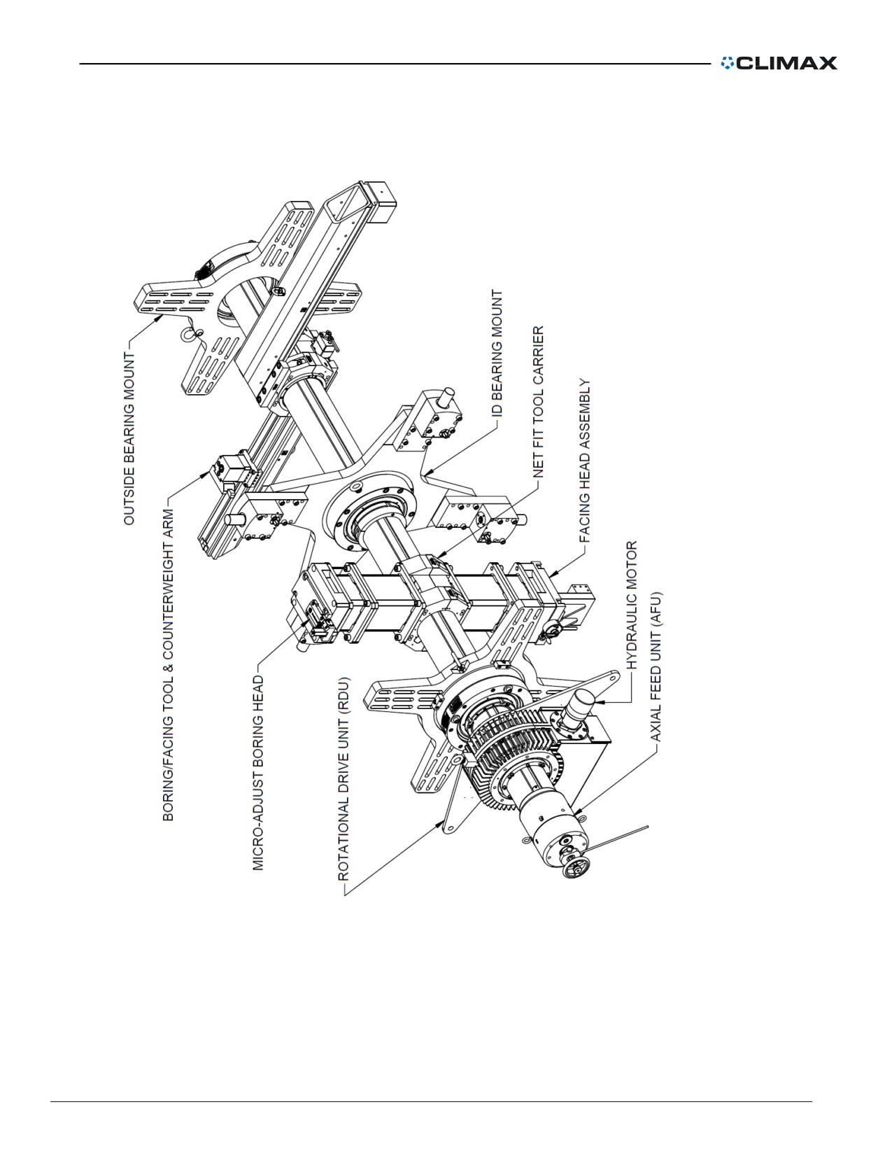
Basic Components
Figure 1. Components
P/N 57064, Rev. 9
Page 7
This page is intentionally left blank
Page 8
BB8100 Operating Manual
OVERVIEW
Model BB8100 Portable Boring Bar is a moving-head style line-boring machine. The 8"
(203 mm) diameter machine will bore 14.5-85.6" (368.3-2,174.2 mm) diameters and face
23.1-97.1" (586.7-2,466.3 mm) diameters.
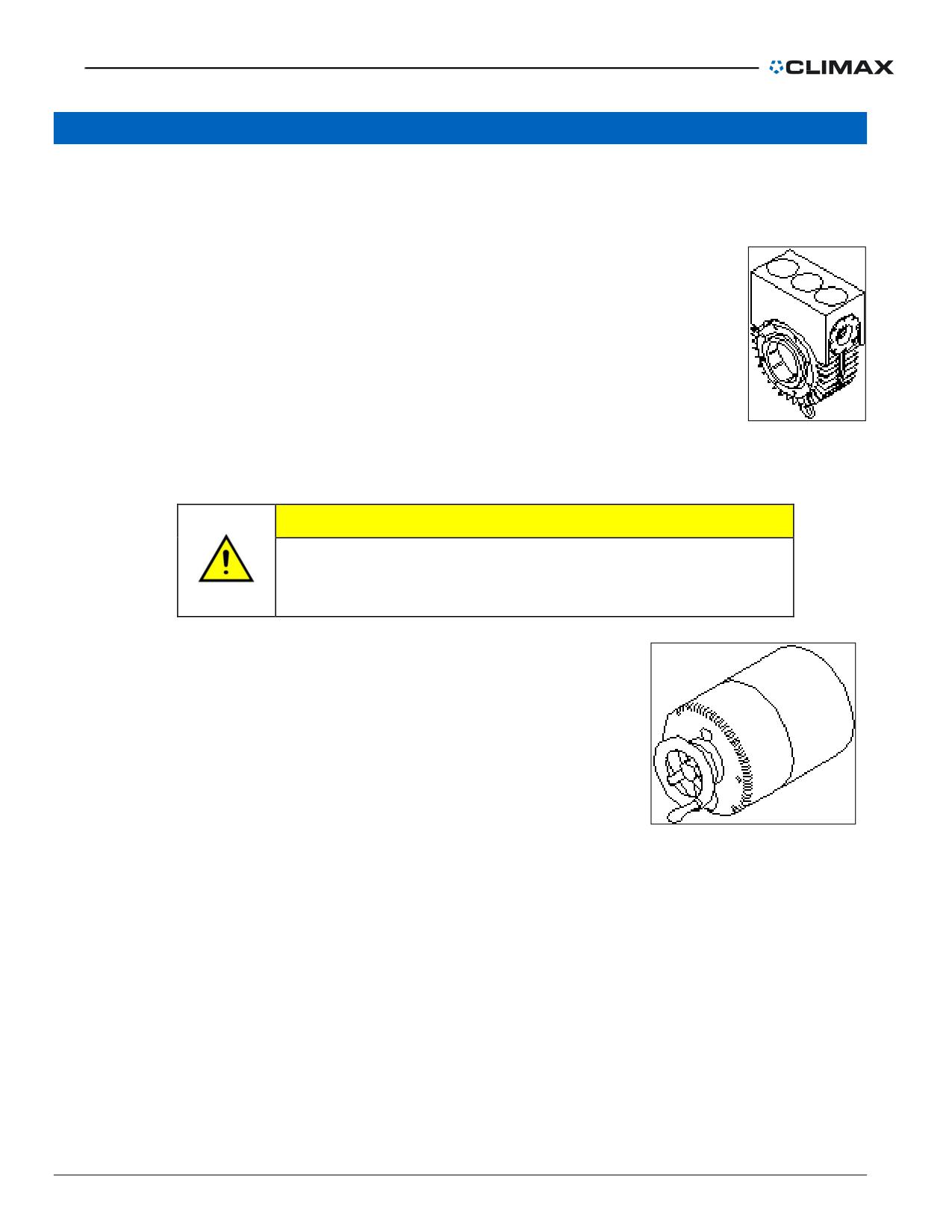
Rotational drive assembly
The rotational drive assembly can be positioned anywhere along the bar.
Locking rings hold the assembly securely in place. Two torque arms
provide stability.
Mechanical axial feed assembly
Figure 2. Rotational
The tool head feeds axially along the bar using the mechanical axial
drive assembly
feed assembly.
CAUTION
If the mechanical axial feed unit is moved to the other end of
the bar, the machine will feed in the opposite direction. Check
the feed direction before operating the machine.
The 8" mechanical axial feed assembly can be
mounted to either end of the boring bar. Feed rate is
reversible and variable up to 0.040" (1.016 mm) per
revolution. Feed direction can be reversed or set to
Neutral by pulling or pushing the shifter knob.
Because the hand wheel component of the axial feed
assembly does not turn while the bar is rotating the
feed rate can be adjusted during operation.
Figure 3. Mechanical axial feed
The assembly includes a 15" (381 mm) trip rod.
assembly
P/N 57064, Rev. 9
Page 9
Hydraulic power
General description
The hydraulic power unit is an electrically driven piston pump with a horizontally mounted
motor. The unit has a 20-gpm pump and a 5-gallon (19 liter) reservoir.
Features include:
• Relief valve for system over pressure protection
• System pressure gage and shut-off valve
• Spin-on oil filter
• Combination fluid level and temperature gage
• Electric motor starter and motor overload heaters.
The hydraulic power unit connects to the rotational drive hydraulic motor with a pair of 25-
foot (7.6-meter) long hoses and quick disconnect fittings. A multi-function pendant controls
the power unit and the machine.
Several hydraulic power units are available. Obtain more information by calling CLIMAX.
CAUTION
To avoid damaging the power unit pump, connect the
hydraulic motor to the power unit before plugging in and
turning on the power unit.
Power unit pendant
The hydraulic power unit comes with a standard control pendant. The pendant, with
25-foot (7.6 m) cord, has the following controls:
• High/low volume control
• Jog/run
• Pressure start
• Pressure stop
• Power unit on
• Power unit off
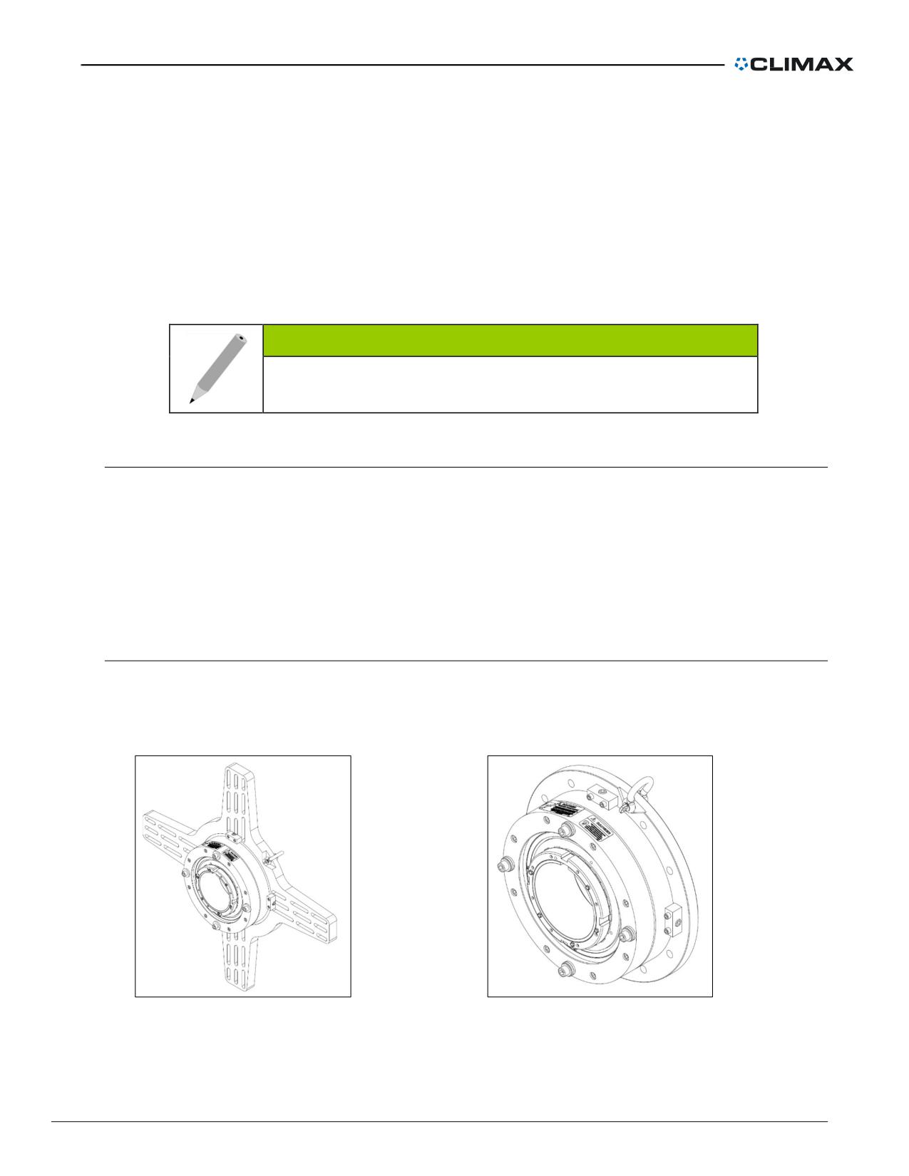
Hydraulic motor
The high-torque low-speed hydraulic motor mounts directly to the rotational drive
assembly. Motor ports are 7/8-14 SAE O-ring type. Motor fittings are included with the
hydraulic power unit. A fitting kit may be purchased separately.
To reverse motor rotation, switch the hydraulic hoses at the motor. The hydraulic fluid that
passes through the motor lubricates the motor during operation.
Page 10
BB8100 Operating Manual
Motors with various displacement ratings are available. Contact your CLIMAX sales
representative for more information.
Bearing support assemblies
The portable boring bar can be set up using two ID-mount bearing assemblies, two end-
mount bearing assemblies, or a combination of bearing assemblies. Bearing support
assemblies can be placed anywhere along the bar.
NOTE
CLIMAX recommends using at least two bearing support
assemblies to ensure machine stability.
End-mount self-aligning bearing support assembly (with spider)
The end-mount bearing support assembly mounts to the end of the work piece through a
slotted spider. The bar is held in place by a self-aligning bearing which can compensate for
bar misalignment up to 1o from perpendicular to the bearing housing.
The 2" (52 mm) thick support spider has four legs and a universal mounting-hole pattern.
The universal mounting-hole pattern allows you to set up the boring bar using existing bolt
holes (if available).
End-mount self-aligning bearing assembly (without spider)
The bearing assembly provides 4-way adjustable bar alignment. The assembly does not
include a spider; it mounts to any existing support structure. See Figure 40 on page 59 for
mounting pattern dimensions. A taper locking adapter secures the bar inside the bearing.
Figure 4. Self-aligning end mount with spider
Figure 5. Self-aligning end mount without spider
P/N 57064, Rev. 9
Page 11
ID-mount non self-aligning bearing support assembly (with spider)
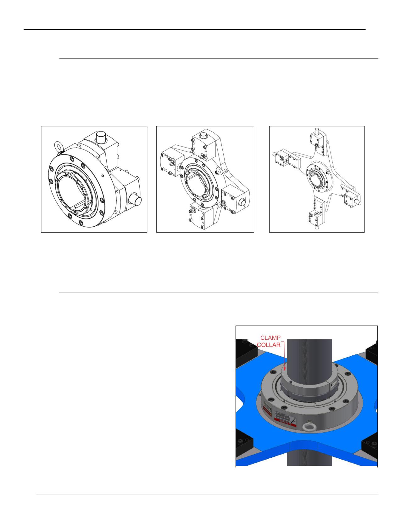
The ID-mount bearing support assembly holds the bar in place with a taper locking
adapter. Center the bar by adjusting the four jaws on the spider. The jaws can be adjusted
from outside the bore.
Bearing support assemblies are available for bores with IDs from 23-77" (584-1,956 mm).
Figure 6. Non-self-aligning ID
Figure 7. Non-self-aligning ID
Figure 8. Non-self-aligning ID
mount with spider (20-35" 508-
mount with spider (34.25-49.25"
mount with spider (48.5-77"
889 mm)
870-1,251 mm)
1,232-1,956 mm)
Non self-aligning bearing assembly (without spider)
The bearing assembly does not include a spider; it mounts to any existing support
structure. See Figure 41 on page 59 for mounting dimensions. A taper locking adapter
secures the bar inside the bearing.
Clamp Collars
The clamp collars (P/N 40708) are made in
matching sets and must be used to secure the
bar when the machine is in the vertical
orientation. This will prevent the bar from sliding
through the support bearings or falling.
To prevent over tightening of the bearings, the
clamp collars should be placed above at least
two support bearings in a vertical orientation.
Figure 9. Clamp collar
Page 12
BB8100 Operating Manual
DANGER
To prevent the bar from sliding through the support
bearings, or falling, use the two clamp collars provided in
the tool kit when using the boring bar in a vertical
orientation. Torque to 100 ft.-lbs.
Boring bar and leadscrew assembly
Model BB8100 uses an 8" diameter bar. Standard bar lengths
are 8 feet to 20 feet (2.44 to 6.10 m) long in 2-foot (.61 m)
increments. Bars of other lengths are available upon request.
The chromed bars have full-length leadscrews. The bar end
caps have anti-friction leadscrew bearings. Because both bar
end caps are the same, the axial feed assembly can be
mounted to either end of the bar.
Figure 10. Boring bar
Axial tool carrier
The axial tool carrier holds the tool head assembly to the bar. The split-design carrier
mounts anywhere along the bar. Boring and facing head assemblies mount to the tool
carrier with screws and, if necessary, spacers. The tool carrier includes a brass nut and
drive key.
Manual boring head assembly
The boring head assembly includes spacers, leading and trailing cartridge holders, carbide
inserts and chip breakers. It requires an 8" (203 mm) tool carrier. Because the tool carrier
is split, the boring head can be mounted anywhere along the bar.
The boring head assembly will bore IDs in a range of 14.5-85.6" (368-2,174 mm),
depending on the number of stack blocks used. The carbide cartridges are micro
adjustable for precision boring. The range of diameters the boring head assembly will cut is
determined by the number of spacers mounted between the tool carrier and boring head.
See the boring head tool range in Table 2 on page 33 and Table 3 on page 34 to
determine how many spacers are needed for your application.
Facing head assembly
The facing head assembly mounts to the 8" (203 mm) tool carrier. Because the tool carrier
is split, the facing head can be mounted anywhere along the bar.
P/N 57064, Rev. 9
Page 13
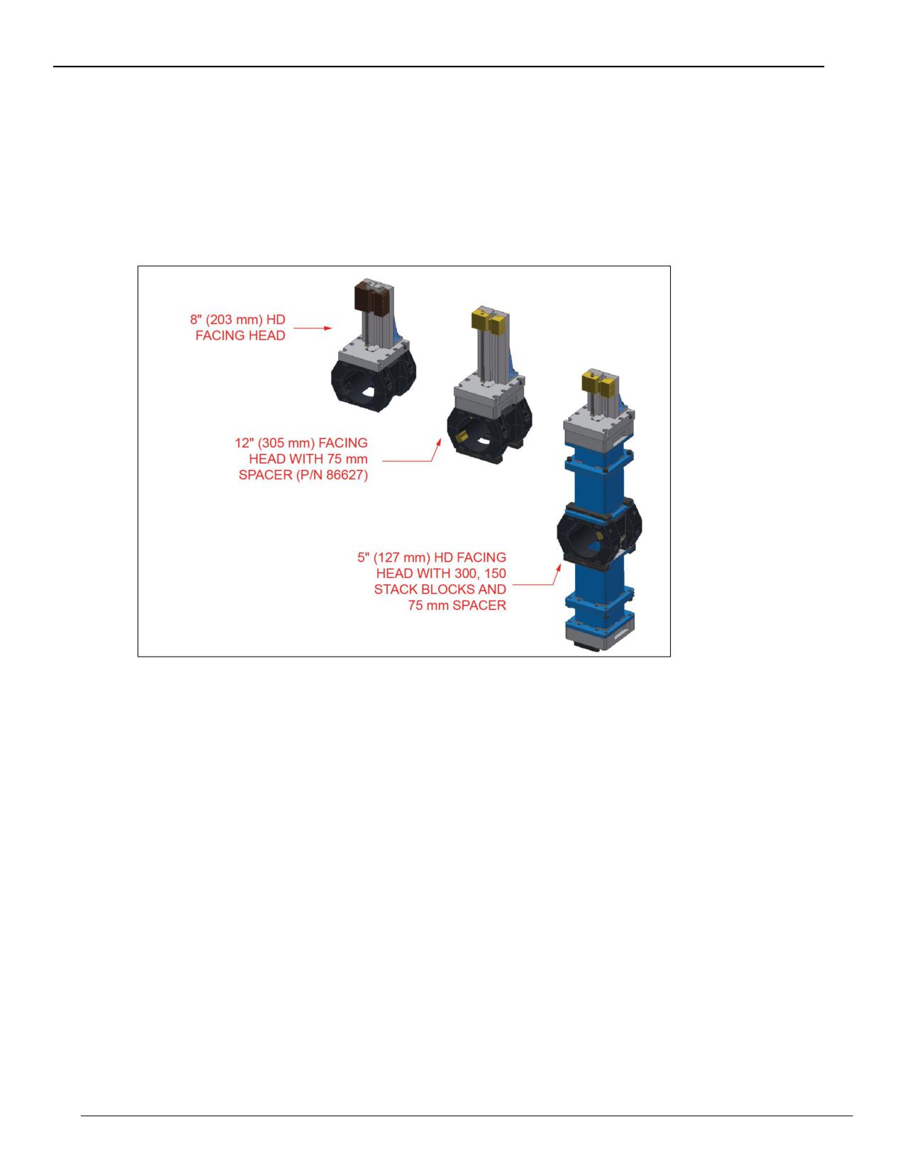
Facing-head assemblies are available with 5" (127 mm), 8" (203.2 mm), or 12" (304.8 mm)
stroke. The range of diameters the machine can face is determined by both the number of
spacers used and the stroke of the facing head.
Feed rate is variable from 0.003-0.025" (0.076-0.635 mm) per revolution.
The facing head uses 1 square-inch tool bits.
Figure 11. Available facing heads and some mounting configurations
Refer to Table 5 on page 41, Table 6 on page 42, and Table 7 on page 43 (depending on
the travel head size) for the facing range of each.
Page 14
BB8100 Operating Manual
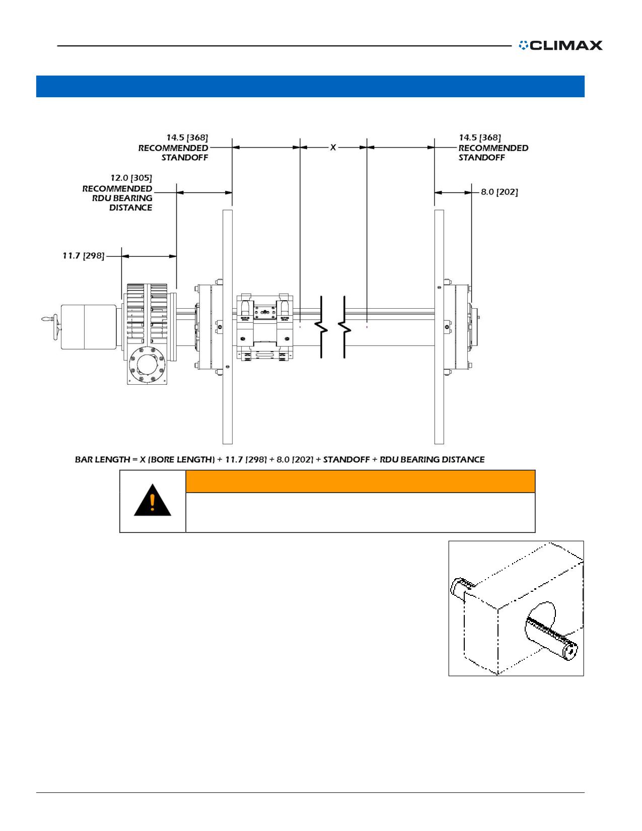
SETUP
WARNING
Rotating and moving parts can seriously injure the operator.
Turn off and lock out the machine before setting it up.
Before setting up the portable boring bar, decide where you will
place each assembly on the bar. Because the rotational drive
and tool head assemblies can be anywhere along the bar, make
sure to provide room for them when setting up the machine.
Boring bar and bearing support assembly
setup
Figure 12. Inserting the
bar into the bore
Clamp Collars
The clamp collars (P/N 40708) are made in matching sets and must be used to secure the
bar when the machine is in the vertical orientation.
P/N 57064, Rev. 9
Page 15
DANGER
To prevent the bar from sliding through the support bearings, or
falling, use the 2 clamp collars provided in the tool kit when using
the boring bar in a vertical orientation. Torque to 100 ft.-lbs (136
Nm).
CAUTION
At least two bearing support assemblies are needed to ensure
machine stability.
NOTE: The bearing mounts may be different styles, depending on application.
End-mount bearing support assembly setup
Though the end-mount bearing support assembly mounts to the outside of the work piece, it can
be placed anywhere along the boring bar.
CAUTION
Bearings placed too far apart allow the bar to deflect, reducing bore
accuracy.
1. Clean the bore of the work with solvent to remove grease, oil, and dirt.
2. Check the bar for nicks or cuts. Dress the bar smooth, if necessary. A bar
with nicks or gouges can damage mating parts (including the tool head
assembly and rotational drive unit) beyond repair. Clean the bar with solvent
to remove dirt and chips.
CAUTION
The bar is not hardened. To prevent damage to the bar, do not strike
it against the bearing supports or against the work piece.
3. Install the bearings at approximately the center
of the bar.
If using existing holes on your workpiece,
make sure they align with the slots in the
spider. Tap 5/8" (16 mm) or 1/2" (13 mm) new
holes if necessary.
If holes are to be tapped, hold the spider
against the work piece and mark the locations
of the slots in the spiders.
Figure 13. Attaching bearing
assemblies
Page 16
BB8100 Operating Manual
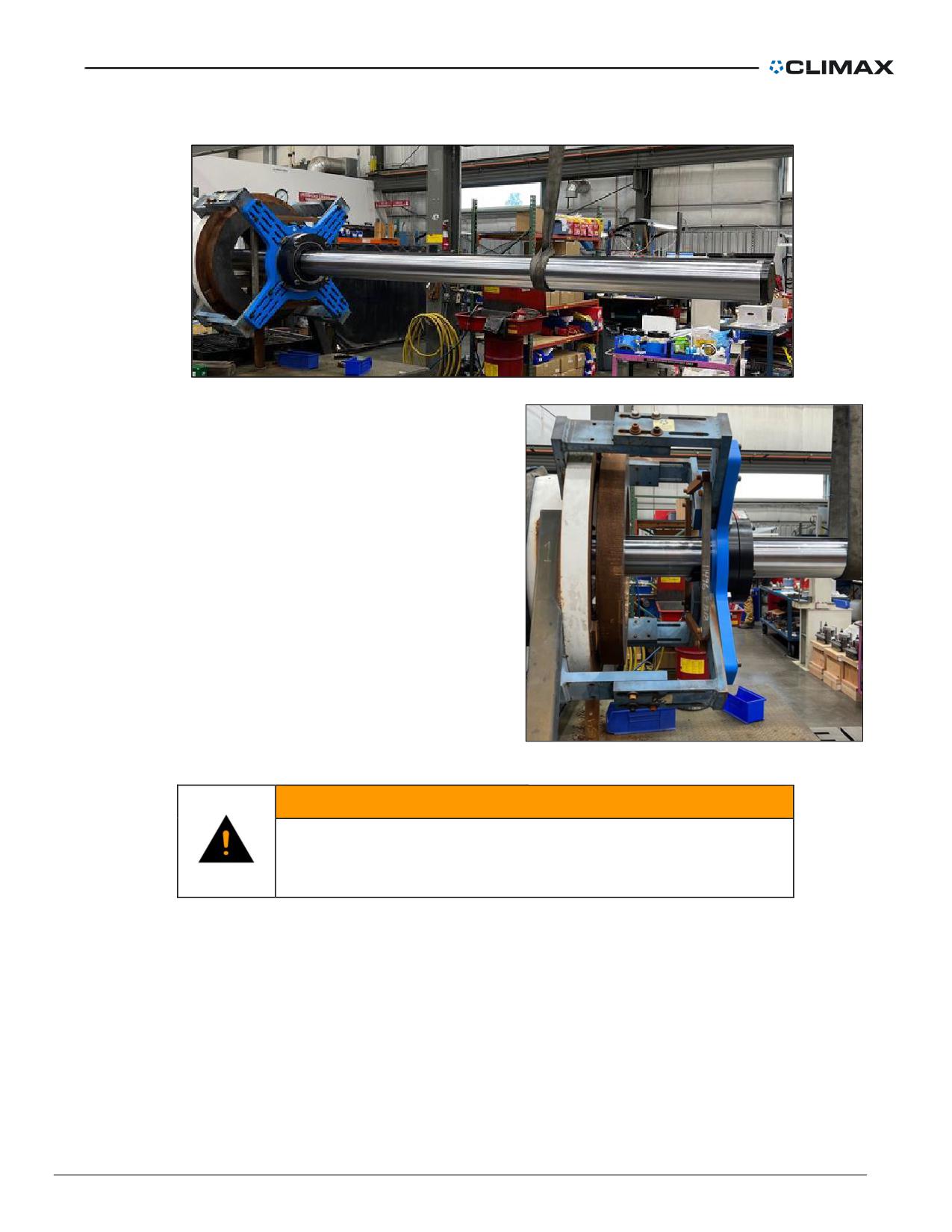
4. Slide the boring bar into the bearings to be machined (see Figure 15).
Figure 15. Boring bar into the bearings
5. Using a hoist, hold the bar and
bearings near the center of the
bore. Alignment should be within
1/8" (3 mm) (see Figure 14).
Figure 14. Centering and aligning the bar
WARNING
Swinging or falling machinery can seriously injure the
operator. Securely wrap the hoist around the bar and bearings
before lifting the machine.
6. If you want to mount the rotational drive assembly between the supports, do it
now. See the “Rotational drive assembly setup” on page 23 for mounting
information.
7. If mounting another end-mount bearing support assembly, repeat steps #4
through #10. If using an ID-mount bearing support assembly, see the “ID-
mount bearing support assembly setup” on page 19. At least two support
assemblies are needed to ensure machine stability.
8. Slide the boring bar through all bearing assemblies.
P/N 57064, Rev. 9
Page 17
NOTE
When completing the following steps, check after each
tightening of the socket set screw flat points (SSSFP) screws
for sufficient remaining set screw travel.
If there is insufficient travel remaining, loosen the SSSFP
screws. Remove the 1/4-28" hex heads (HHCS) and restart
from step a.
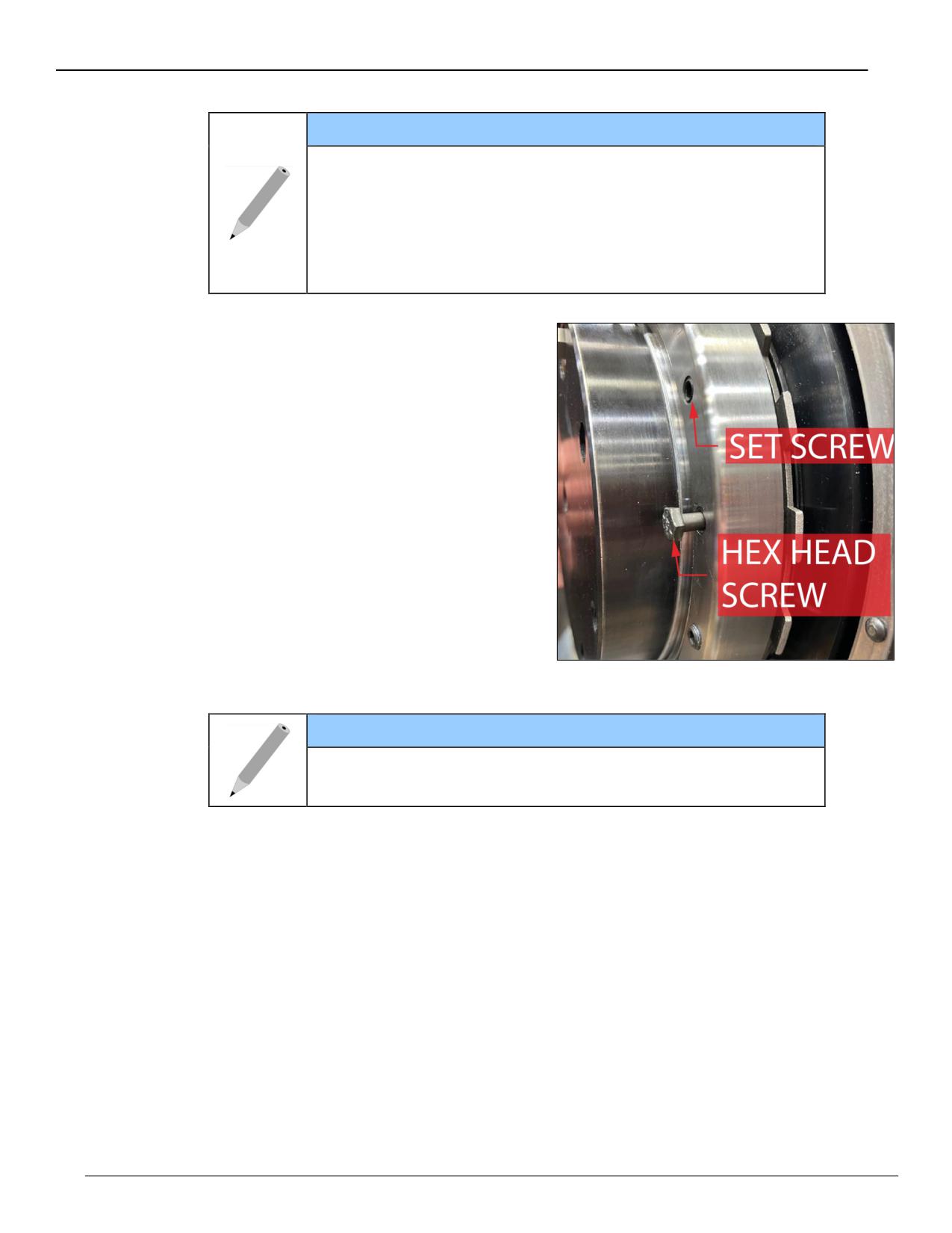
9. Lock the bar in place by tightening
the taper lock by doing the
following:
a) Tighten the taper lock nut onto
the bar.
b) Insert the 1/4-28" hex head
cap screws (HHCS) through
the lock nut and washer into
the taper. Leave them loose as
they are used to disassemble
the bearing after operation.
c) Tighten the 3/8-24" socket set
screw flat points (SSSFP) to
23 ft-lb. The purpose of this is
to tension the taper and nut to
clamp the bar.
Figure 16. Set screw and hex head screw
NOTE
The purpose of step c is to tension the taper and nut to clamp
the bar.
d) Rotate the bar one and a half rotations to seat the taper lock.
e) Repeat steps c and d until the torque remains at 23 ft-lb after one and a
half rotations.
Page 18
BB8100 Operating Manual
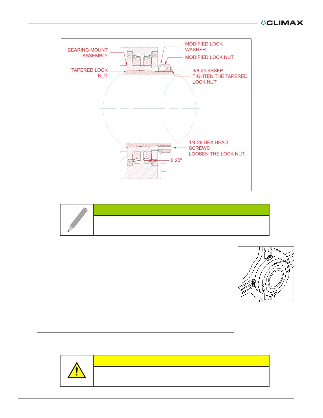
Figure 17. Tightening the bearing assemblies to the bar
NOTE
The six 1/4-28 hex head cap screws loosen the tapered lock
nut.
10. Precisely align the boring bar:
a) Position a dial indicator to check concentricity
between the boring bar and the bore.
b) Adjust the screws in the centering blocks until the
bar is centered.
Figure 18. Bearing
assembly
ID-mount bearing support assembly setup
Though the ID-mount bearing support assembly mounts inside the work piece, it can be placed
anywhere along the boring bar.
CAUTION
Bearings placed too far apart allow the bar to deflect, reducing
bore accuracy.
P/N 57064, Rev. 9
Page 19
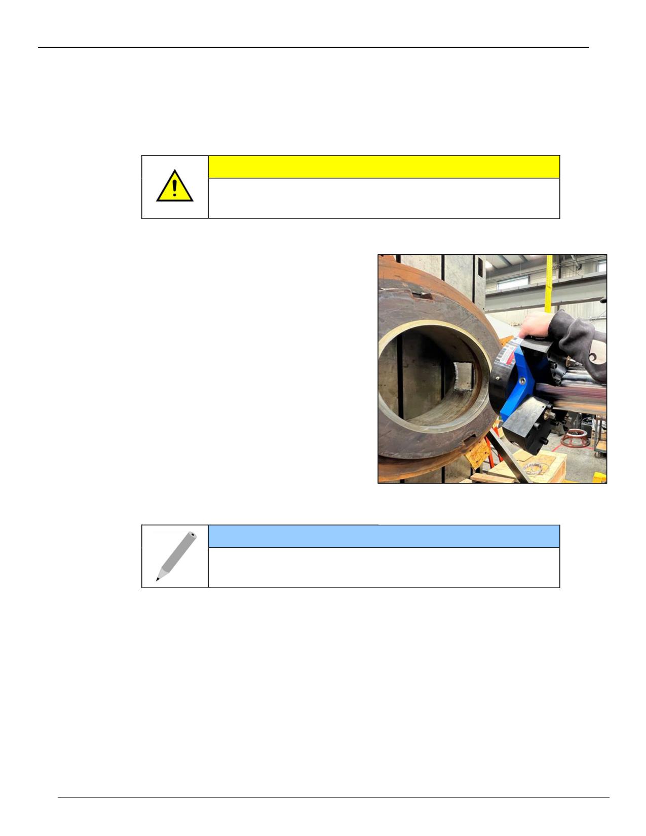
1.
Clean the bore with solvent to remove grease, oil, and dirt.
2.
Examine the bar for nicks or cuts. Dress it smooth if necessary. A bar with
nicks or gouges can damage mating parts (including the tool carrier assembly
and rotational drive unit) beyond repair. Clean the bar with solvent to remove
dirt and chips.
CAUTION
The boring bar is not hardened. To prevent damage to the bar,
do not strike it against the bearing supports or the work piece.
3.
Measure the diameter of the bore into which the bearing will fit. Using Table 1
on page 22, select the components required.
4.
Position one bearing support
assembly on the bar. Tighten the
lock nut using the impact spanner
wrench in the tool kit.
a) Tighten the taper lock nut onto
the bar.
b) Insert the 1/4-28" hex head
cap screws (HHCS) through
the lock nut and washer into
the taper. Leave them loose as
they are used to disassemble
the bearing after operation.
c) Tighten the 3/8-24" socket set
screw flat points (SSSFP) to
23 ft-lb. The purpose of this is
to tension the taper and nut to
Figure 19. Positioning the bearing support
clamp the bar.
assembly on the bar
NOTE
The purpose of step c is to tension the taper and nut to clamp
the bar.
d) Rotate the bar one and a half rotations to seat the taper lock.
e) Repeat steps c and d until the torque remains at 23 ft-lb after one and a
half rotations.
Page 20
BB8100 Operating Manual
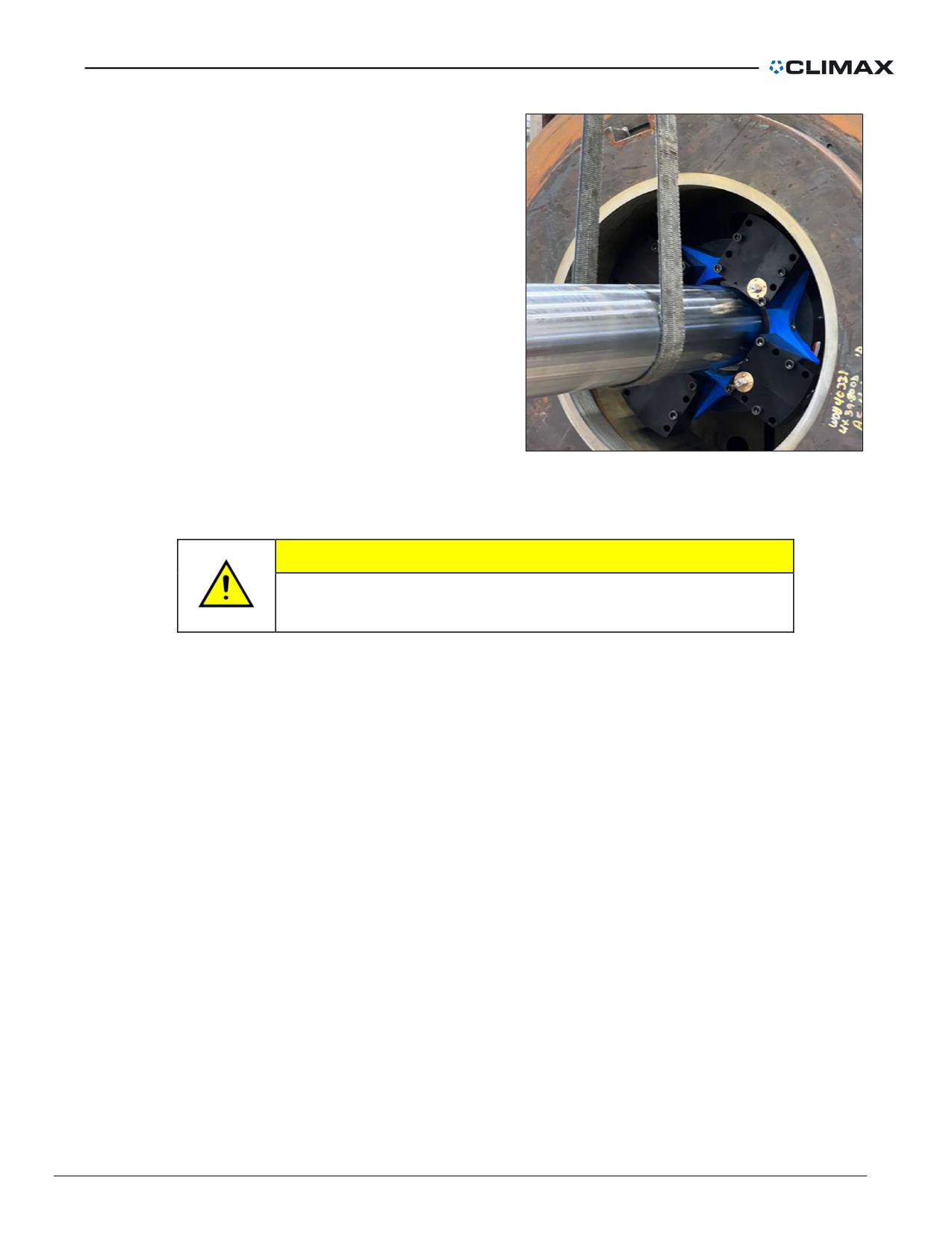
5.
Slide the bar and bearing into the
workpiece.
6.
Using a dial indicator and the jaw
crankshafts, center the bar in the
work piece. Turn the crankshafts
until the jaws are tight in the bore.
Do not exceed 22 ft-lbs (30 Nm) of
torque.
7.
If you wish to mount the rotational
drive assembly between the
bearing supports, do it now. See
“Rotational drive assembly setup”
on page 23 for instructions.
8.
If mounting another ID-mount
bearing, repeat Steps #3 through
#7. If mounting an end-mount
Figure 20. Insert the bar and bearing
bearing support assembly, see
“End-mount bearing support
assembly setup” on page 16.
CAUTION
Bearings placed too far apart allow the bar to deflect, reducing
bore accuracy.
9.
Check that the bar is centered by sweeping a dial indicator inside the bore.
Adjust the jaws if necessary.
P/N 57064, Rev. 9
Page 21
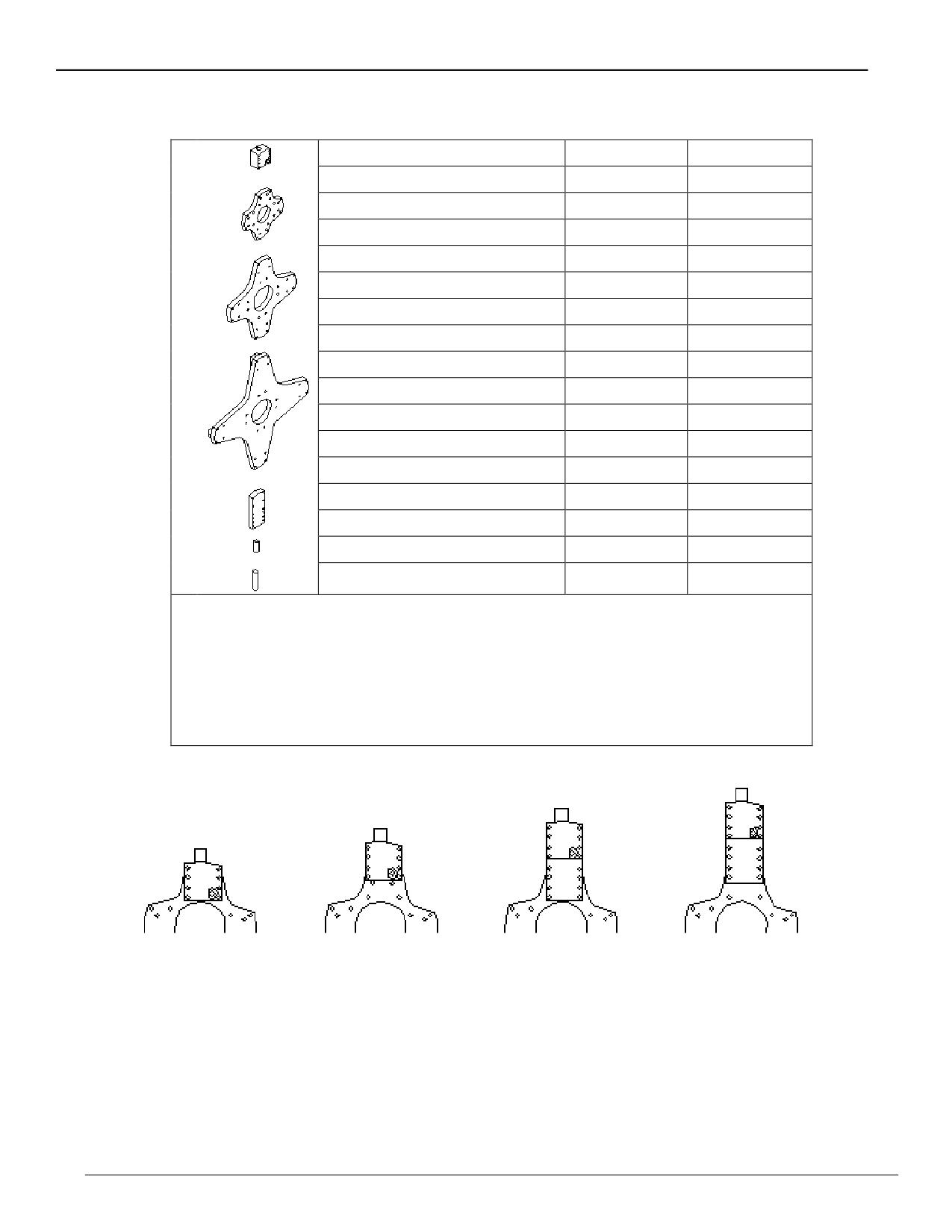
Table 1. ID-mount bearing assembly bore diameter range
Bore diameter range inch (mm)
Parts required
Setup position
1
20.0 - 23.75 (508.0 - 603.3)
1, 2, 6
A
23.75 - 27.50 (603.3 - 698.5)
1, 2, 6
B
2
27.5 - 31.25 (689.5 - 793.8)
1, 2, 7
A
31.25 - 35.0 (793.8 - 889.0)
1, 2, 7
B
34.25 - 38.0 (870.0 - 965.2)
1, 3, 6
A
3
38.0 - 41.75 (965.2 - 1060.5)
1, 3, 6
B
41.75 - 45.5 (1060.5 - 1155.7)
1, 3, 7
A
45.5 - 49.25 (1155 - 1251.0)
1, 3, 7
B
48.5 - 52.25 (1231.9 - 1327.2)
1, 4, 6
A
4
52.25 - 56.0 (1327.2 - 1422.4)
1, 4, 6
B
56.0 - 59.75 (1422.4 - 1517.7)
1, 4, 7
A
59.75 - 63.5 (1517.7 - 1612.9)
1, 4, 7
B
62.75 - 66.5 (1593.9 - 1689.1)
1, 4, 5, 6
C
5
66.5 - 70.25 (1689.1 - 1784.4)
1, 4, 5, 6
D
6
70.25 - 74.0 (1784.4 - 1879.6)
1, 4, 5, 7
C
7
74.0 - 77.0 (1879.6 - 1955.8)
1, 4, 5, 7
D
1.
Centering Block
2.
Spider 20” - 35” (508 - 889 mm) diameter
3.
Spider 34.75” - 49.25” (882.65 - 1250.95mm) diameter
4.
Spider 48.5” - 63.5” (1231.9 - 1612.9mm)
5.
Extension
6.
Jaw 4.625 (117.47mm)
7.
Jaw 8” (203.2mm)
Setup A
Setup B
Setup C
Setup D
Centering block
Centering block
Extension closest to
Extension farthest
closest to the center
farthest from the
the center of the
from the center of
of the spider
center of the spider
spider
the spider
Page 22
BB8100 Operating Manual
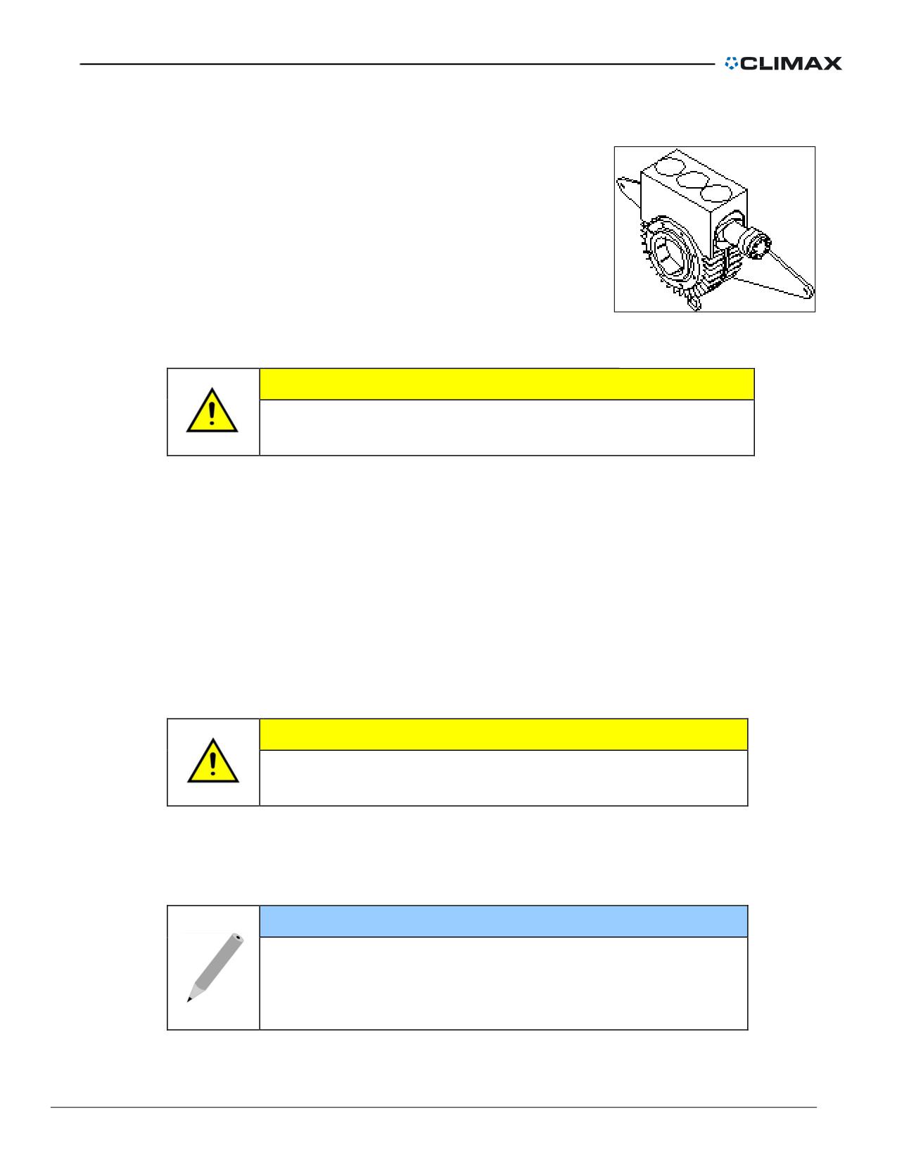
Rotational drive assembly setup
The rotational drive assembly can be placed anywhere on the
boring bar.
Figure 21. Rotational drive
assembly
CAUTION
The boring bar is not hardened. To prevent damage, do not
strike it against the bearing supports or the work piece.
1.
Mount the torque arms to the rotational drive housing
2.
Mount the hydraulic motor to the rotational drive housing, if necessary. Check
that the mounting bolts are tight.
3.
Loosen the socket-head screws. Push the locking rings out by screwing in
the four socket set screws.
4.
Slide the rotational drive assembly along the boring bar.
5.
Remove one of the locking rings to gain access to the RDU keyway.
6.
Insert the drive key into the boring bar leadscrew groove. Check that the key
meshes with the leadscrew.
7.
Slide the key along the groove and into the RDU keyway.
CAUTION
The rotational drive key must be in place before operating the
boring bar. Failure to do so may damage the machine.
8.
Replace the locking ring after the key is installed.
9.
Lock the rotational drive assembly to the bar by tightening the socket-head
cap screws.
NOTE
Tighten only the eight socket-head cap screws in the locking
rings, not the four setscrews. The setscrews loosen the
locking rings. Back out the setscrews before clamping the
rings to avoid damage to the rings.
P/N 57064, Rev. 9
Page 23
10. Secure the torque arms.
WARNING
Loose torque arms can swing uncontrollably injuring the
operator and damaging the machine. Secure the torque arms
to a stationary structure strong enough to withstand the full
torque of the rotational drive unit.
11. Connect the hydraulic motor lines to the hydraulic power unit.
CAUTION
To avoid damaging the hydraulic power unit pump, connect
the hydraulic motor to the power unit before plugging in and
turning on the power unit.
Mounting the axial feed assembly to the bar
The mechanical axial feed unit can be mounted to either end of the boring bar.
1. Place the axial feed unit in NEUTRAL so the leadscrew drive can rotate in
either direction. See “Setting the feed direction” for instructions.
2. While holding the axial feed unit against the bar end cap, turn the feed unit
output shaft until the hex in the end of the leadscrew engages
3. Tighten the two mounting bolts into the end cap to secure the feed assembly
to the bar.
4. Secure the axial feed unit stop rod to a stationary structure so it will trip the
feed mechanism. The rod should be sufficiently free to be removed if
necessary.
Page 24
BB8100 Operating Manual
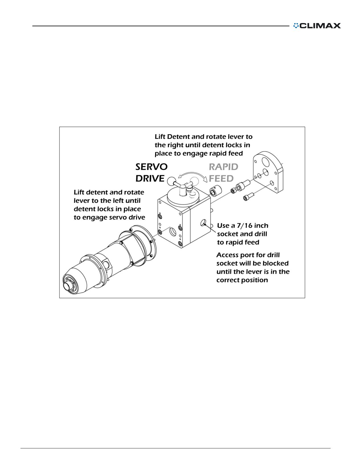
Attaching the Mechanical Rapid Feed (optional equipment)
The optional mechanical rapid feed attachment fits between the axial feed assembly and the end
of the boring bar. It has a side port for a standard 7/16” drill socket, used to rapid advance the
feed. The lever engages and disengages the rapid feed system.
When engaged, access to the drill socket port is available. Access to this drill socket port opens
and closes when the lever is switched between servo and rapid feed mode. This prevents
operator error. When the servo is engaged, the drill socket will not fit into the port. Drawings and
part numbers are found in the following pages.
Rapid Advance is available using your hand drill and a 7/16" (11 mm) drive socket (included).
Typical rapid feed rates using your 0-400 RPM drill is 0.0-32" (0.0-813 mm)/min.
P/N 57064, Rev. 9
Page 25
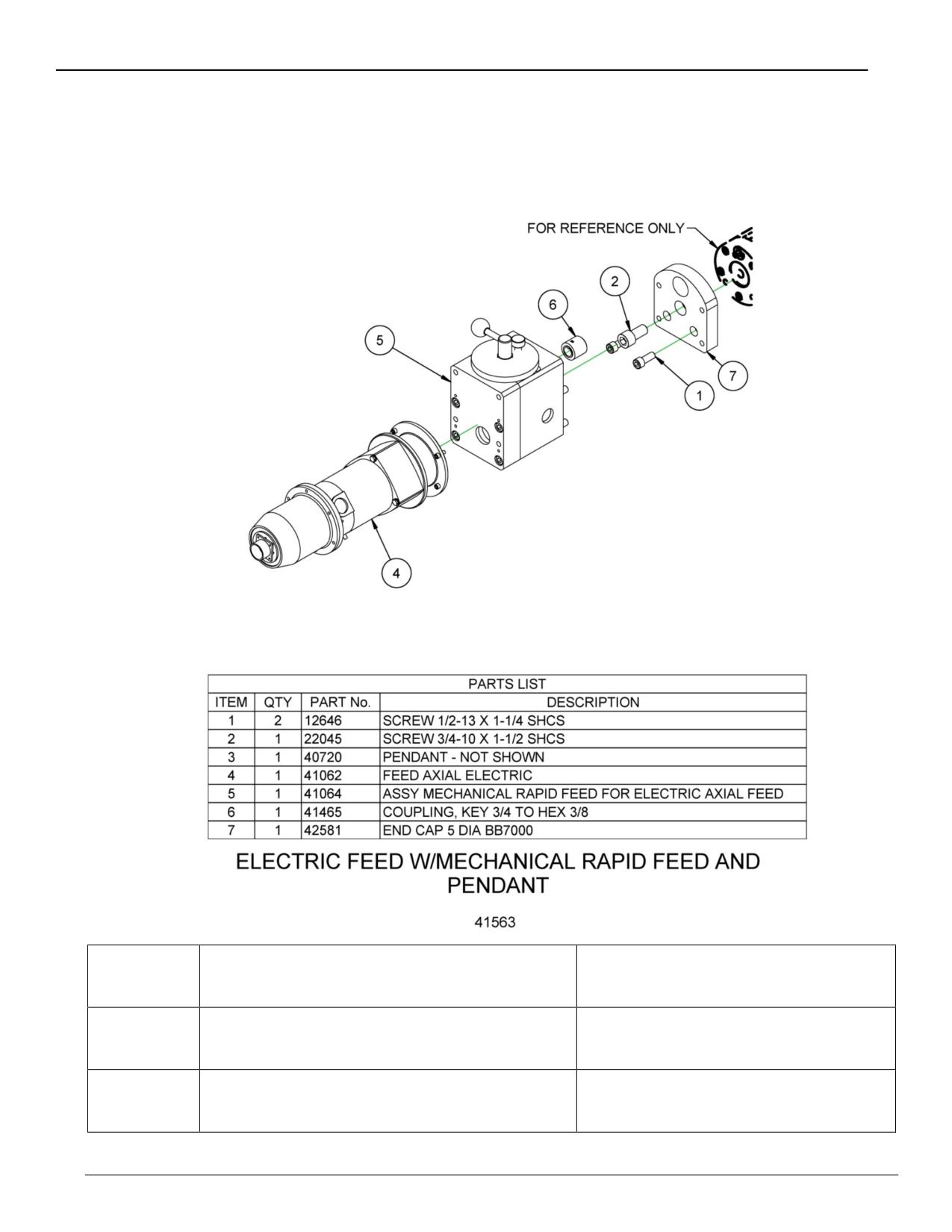
Electric feed with rapid feed shown below for the BB7000/7100 model.
A special adaptor plate allows you to easily connect the electric feed/ mechanical gearbox
assembly to CLIMAX 3.5, 5, 6, and 8" (88.9, 127, 152.4, and 203.2 mm) boring bars. Adapters
are also available for competitive boring systems.
P/N 43735
Electric Feed Assembly for
3.5" (88.9 mm) diameter bar
BB6000/BB6100
P/N 43736
Electric Feed Assembly for
5 or 6" (127 or 152.4 mm) diameter
BB7000/BB7100 or BB8000/BB8100
bar
P/N 43734
Electric Feed Assembly for
8" (203.2 mm) diameter bar
BB8000/BB8100
Page 26
BB8100 Operating Manual
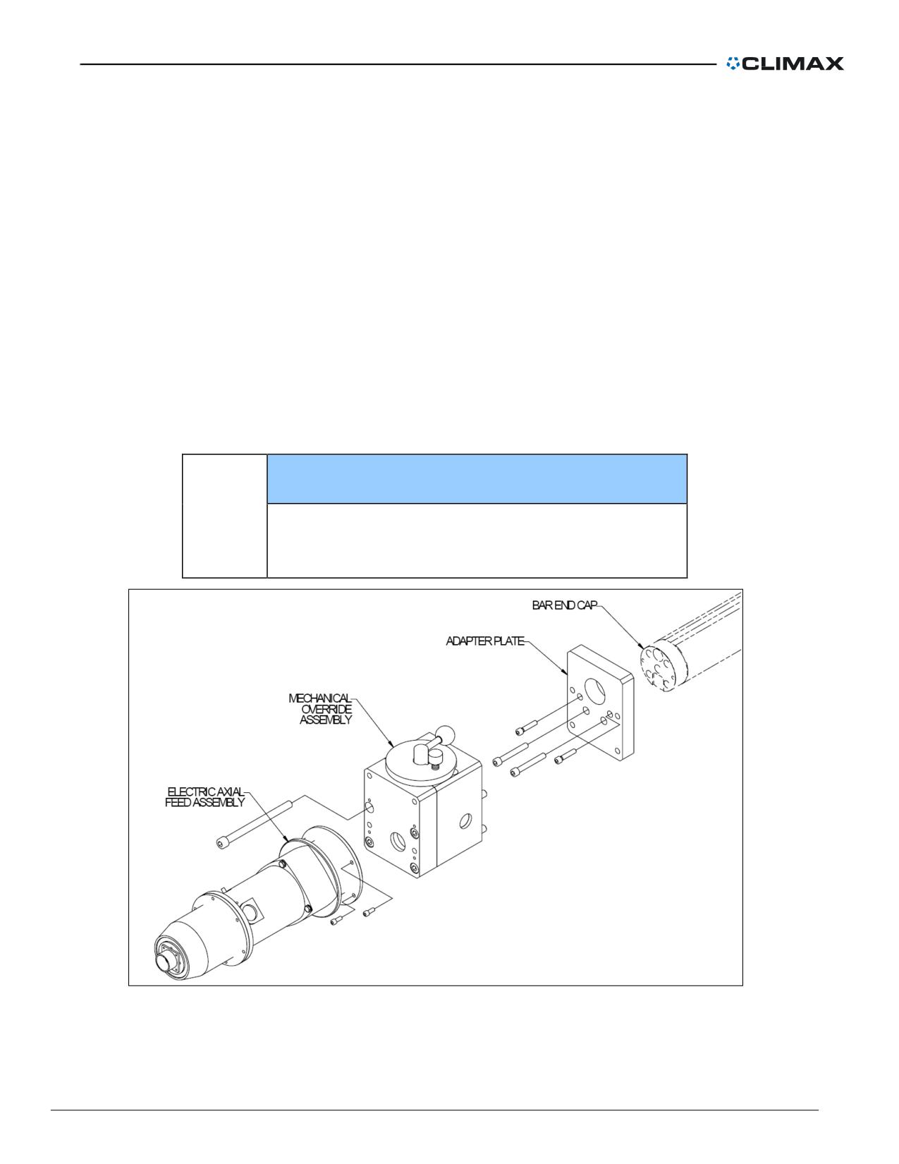
Mounting an optional electric axial feed assembly
The electric feed unit consists of the adaptor plate, manual override, electric motor assembly, and
remote pendant control.
The axial feed unit can be mounted to either end of the boring bar. The locating nose and hex nut
hole of the feed unit fit into the locating nose seat and protruding hex shaft of the boring bar end
cap.
1. Mount the adapter plate to the end of the bar using the ¾-10 cap screw and
two ½-13 cap screws.
2. Mount the mechanical override assembly to the adaptor plate. Make sure the
hex in the mechanical override is aligned with the hex on the lead screw.
3. Mount the electric axial feed assembly to the back of the mechanical override
with 4 cap screws.
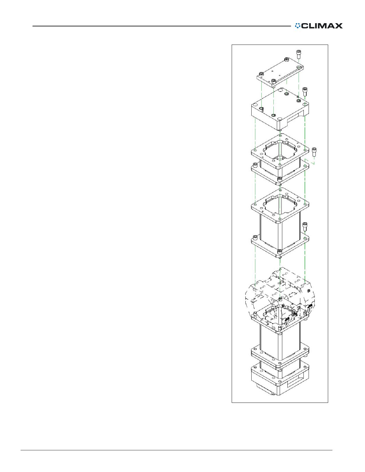
4. Check that the keyway is aligned in the coupling.
5. Attach the pendant electrical cable to the rear of the electric axial feed.
NOTICE
If the axial feed unit is moved to the opposite end of
!
the bar, the feed direction will reverse. Check feed
direction before operating the machine.
Figure 22. Mounting the rapid feed electric axial feed assembly
P/N 57064, Rev. 9
Page 27
Setting the Axial Feed Rate
The feed potentiometer controls the axial feed rate. Turning the knob counterclockwise decreases
the feed rate; turning the knob clockwise increases the feed rate.
Axial feed rate is adjustable and variable from 0.010-0.500" (0.25-13 mm) per minute.
Setting the feed direction
Setting feed direction while the bar is rotating
The axial feed unit has three positions: NEUTRAL, FORWARD, and REVERSE.
1. To set the feed to FORWARD (tool feeds AWAY FROM the axial feed unit),
push and hold the shifter knob in toward the axial feed unit until you feel the
feed engage.
2. To set the feed to REVERSE, (tool feeds TOWARD the axial feed unit), pull
and hold the shifter knob out away from the axial feed unit until you feel the
feed engage.
3. To set the feed to NEUTRAL, position the shifter knob half way between
FORWARD and REVERSE.
NOTE
The higher the feed rate, the faster the axial feed unit will
engage.
Setting feed direction when the bar is stopped
1. Insert a 1/2" hex wrench into the hex hole in the dial.
2. While pushing or pulling the shifter handle, slightly turn the wrench 1/6 of a
turn or less.
3. When the feed is fully engaged, the hex wrench will turn only in the direction
the feed is set. If the feed is in NEUTRAL, the wrench will turn in either
direction.
WARNING
To avoid damage, check that the feed is fully engaged
before running the machine.
Disengaging the feed
1. Set the feed to zero or remove the axial feed stop rod to limit the tool feed.
2. If the bar is rotating, see ”Setting feed direction while the bar is rotating” on
page 28 for instructions to set the feed to NEUTRAL.
If the bar is not moving, see “Setting feed direction when the bar is stopped”
on page 28 for instructions to set the feed to NEUTRAL.
Page 28
BB8100 Operating Manual
3. Replace the stop rod, if necessary.
4. Check that the tooling is not moving.
Setting the feed rate
Axial feed rate is fully adjustable up to 0.040" (1.016 mm) per revolution.
Adjust the feed rate by lifting the spring plunger with one hand and turning the hand wheel with
the other. Turn clockwise to reduce the feed; counter-clockwise to increase the feed. The feed
can be adjusted while the bar is rotating.
CAUTION
The feed has solid stops at maximum and minimum feed
positions. To avoid damage, do not force the hand wheel past
the solid stops.
A feed dial on the axial feed unit shows the feed speed when the bar is rotating.
Tooling setup
Tool carrier setup
Tool head assemblies require a tool carrier to mount to the boring bar.
Do the following to mount the tool carrier:
1. Check the bar for nicks or cuts. Dress the bar smooth if necessary. A bar with
nicks or gouges can damage mating parts (including the tool head assembly
and the rotational drive unit) beyond repair. Clean the bar with solvent to
remove dirt and chips.
2. Position the carrier nut and carrier key inside the tool carrier.
3. Tighten the mounting screws.
4. Mount the two halves of the tool carrier onto the boring bar. Check that the
leadscrew nut engages with the leadscrew.
5. Tighten the socket-head cap screws.
6. Lightly oil the boring bar and leadscrew.
P/N 57064, Rev. 9
Page 29
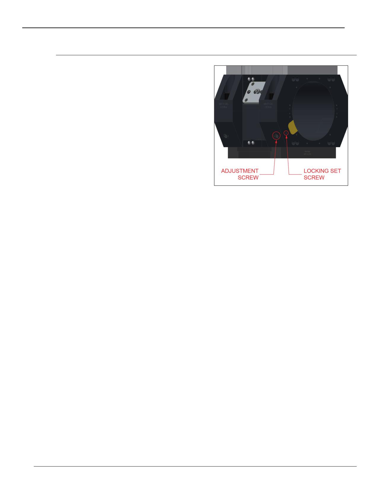
To lock the tool carrier on the bar for other operations
1. Loosen the setscrew on the side
of the tool carrier.
2. Tighten or loosen the
adjustment screw.
3. Tighten the setscrew to keep
the adjustment screw in
position.
Figure 23. Adjustment and set screws in the
tool carrier
Page 30
BB8100 Operating Manual
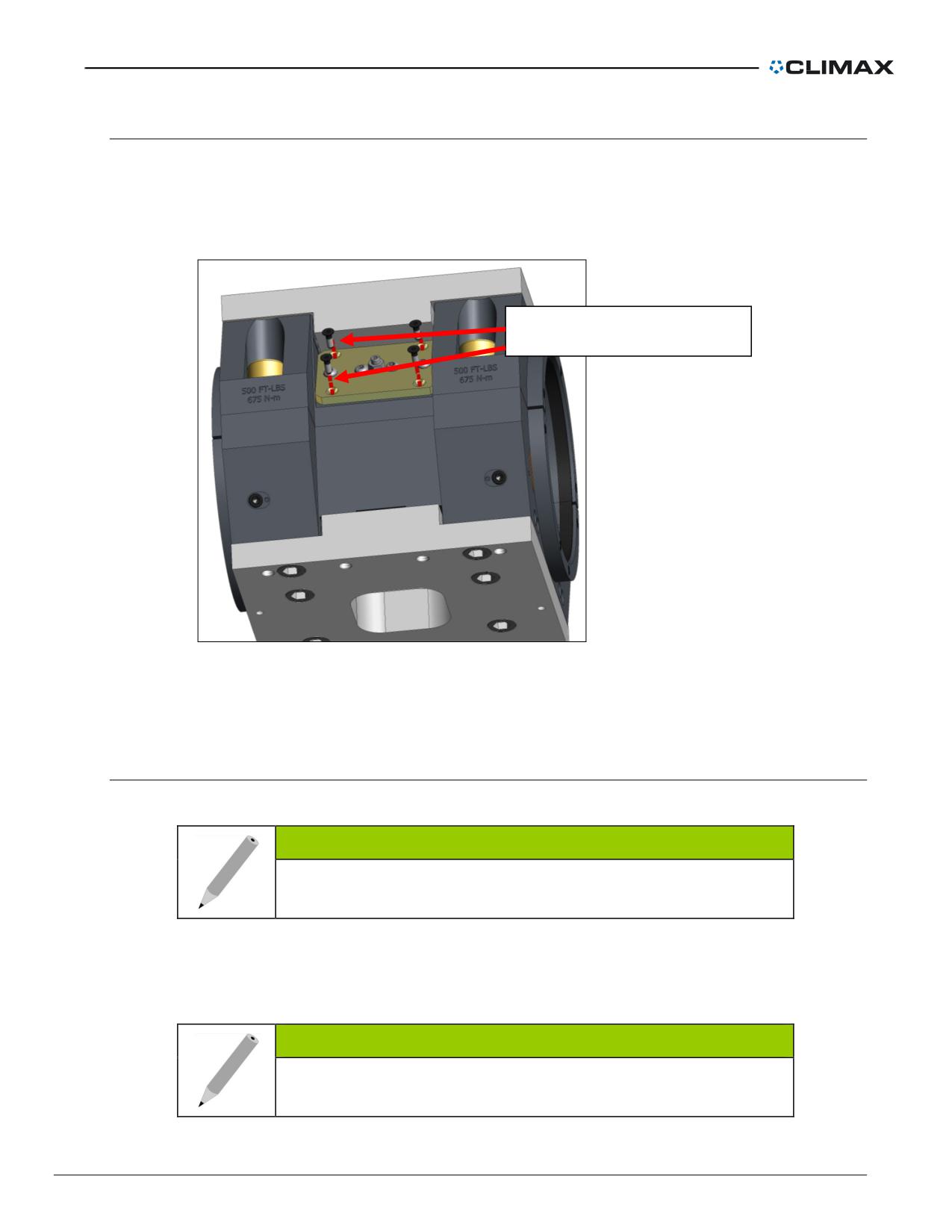
To remove the brass nut
1. Do not remove all the screws.
2. Remove the screws on each corner of the brass nut.
3. If there is too much play in the brass nut, the center set screw can be
tightened.
To remove the brass nut
Figure 24. Screws to remove the brass nut
Boring
Manual boring head assembly setup
The manual boring assembly requires the tool carrier to mount it to the boring bar.
NOTE
The bar can rotate either direction. Check that the tooling
faces the correct direction.
Using the boring head tool range in Table 2 on page 33 and Table 3 on page 34, select
appropriate spacers and screws and assemble the tool carrier.
NOTE
Precision bores are best achieved by boring several rough
cuts and one shallow finish bore.
P/N 57064, Rev. 9
Page 31
NOTE
Parts listed are for one side of the carrier only. Identical
parts are required for the other side.
Micro Adjustment Boring Head
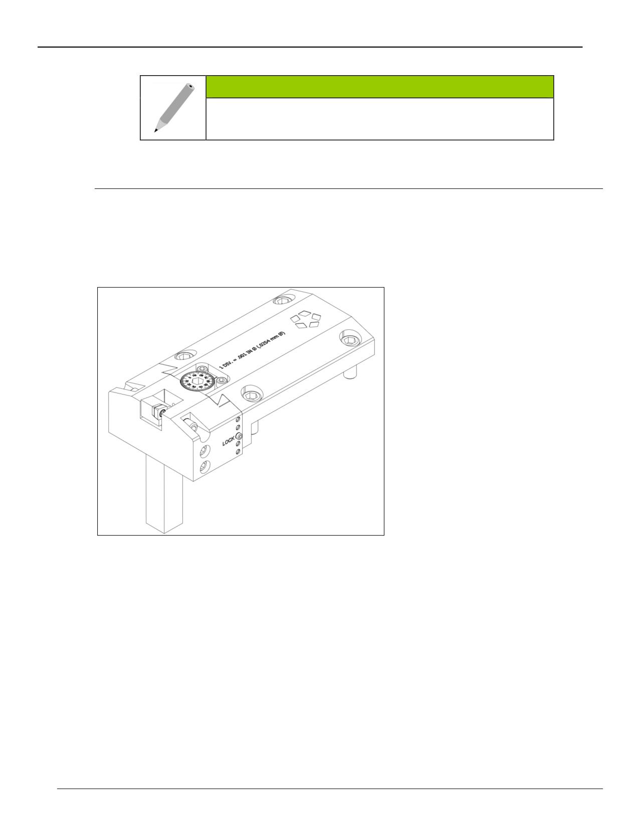
The micro-adjust boring head offers the possibility to micro-adjust readily available off-the-
shelf square shank tooling for boring. The micro-adjust travel is 0.5" (13 mm), and the
ability to slide the tool without having to change the setup provides a total tool travel of
more than 2" (per setup).
Figure 25. Micro-adjust boring head
To set the tool to the desired diameter, simply feed the dial screw until reaching it and then
lock the middle dove tail set screw with the provided T handle hex drive. Each division in
the dial screw resolves in 0.001" (0.025 mm) change in diameter. The dove tail adjustment
set screws are set to the correct load by CLIMAX and should not be necessary to re-adjust
them. These set screws have Vibratite-VC3 in order to avoid losing tension during
vibration. The lock also has this compound, and it might be necessary to re-apply some
every once in a while, if necessary.
The BB8100 comes with a 1 square-inch shank tool holder.
To set up leading and trailing, simply shift the boring heads against the mounting screws in
opposite directions.
There is a small set screw that stops the tool carriage from being removed from its holder,
and the boring head should never be operated without it on.
Page 32
BB8100 Operating Manual
Proper maintenance would involve cleaning and lubricating the dove tail surfaces and the
dial screw threads and groove, and if the lock set screw feels loose after a while, applying
the provided Vibrative vc-3.
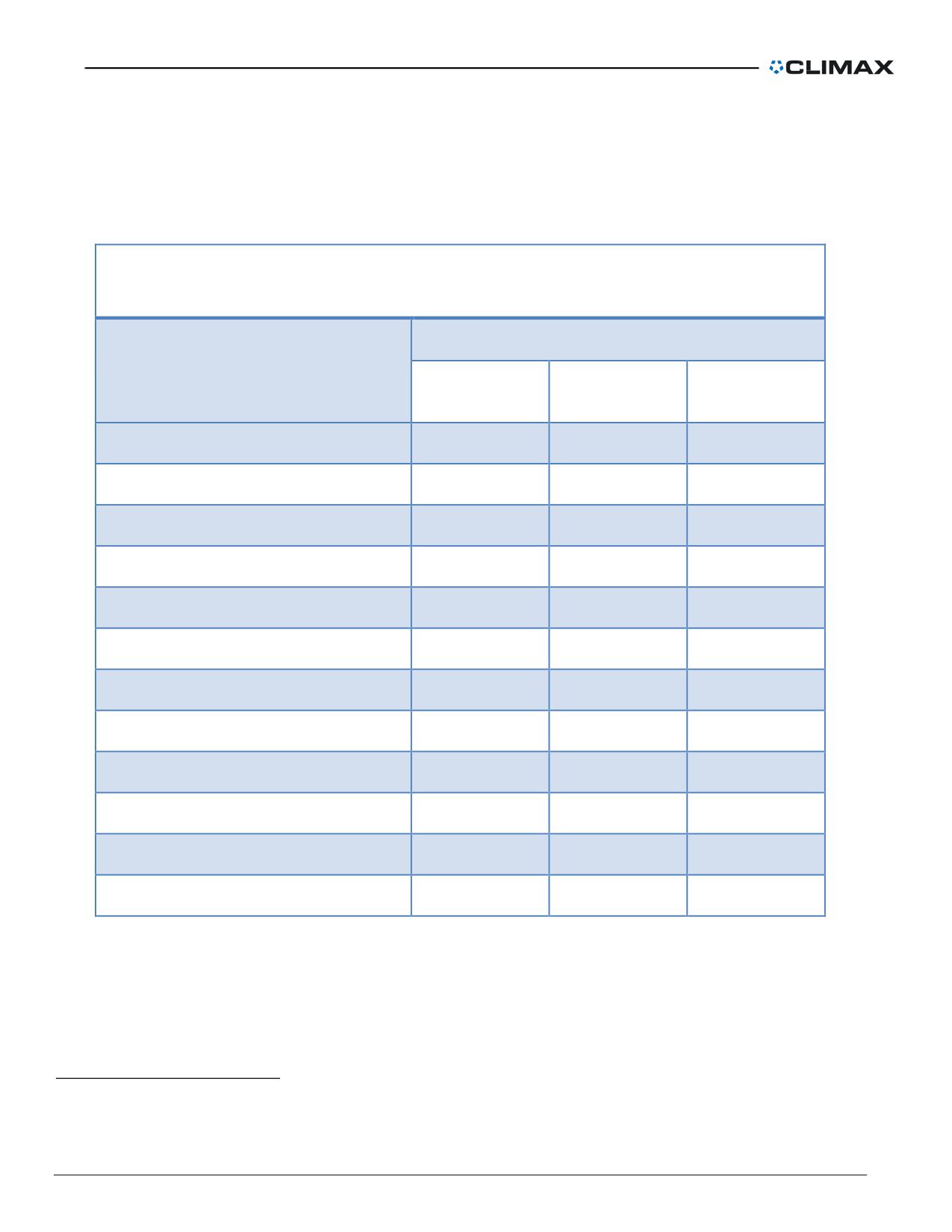
Table 2. Micro adjust boring head tool range table
BB 8100 MICRO ADJUST BORING HEAD TOOL RANGE TABLE
14.5-85.6" (368-2,174 MM) DIAMETER
NUMBER OF SPACER BLOCKS REQUIRED
BORE RANGE DIAMETER
2.95" (76 mm)
5.9" (150 mm)
11.8" (300 mm)
block
block
block
14.5-21.5" (368-546 mm)1
0
0
0
20.4-27.4" (518-696 mm)
1
0
0
26.3-33.3" (668-846 mm)
0
1
0
32.2-39.2" (818-996 mm)
1
1
0
38.1-45.1" (968-1,146 mm)
0
0
1
44-51" (1,118-1,295 mm)
1
0
1
49.9-56.9" (1,267-1,445 mm)
0
1
1
55.8-72.8" (1,417-1,849 mm)
1
1
1
61.7-68.7" (1,567-1,745 mm)
0
0
2
67.6-74.6" (1,717-1,895 mm)
1
0
2
73.5-80.5" (1,867-2,045 mm)
0
1
2
79.4-86.6" (2,017-2,200 mm)
1
1
2
1 The tool holder must be shortened to avoid hitting the bar OD at the minimum diameter.
P/N 57064, Rev. 9
Page 33

Table 3. Solid tooling boring head tool range table
BB 8100 SOLID TOOLING BORING HEAD TOOL RANGE TABLE
14.5-86.6" (368-2,200 MM) DIAMETER
NUMBER OF SPACER BLOCKS REQUIRED
BORE RANGE DIAMETER
2.95" (76 mm)
5.9" (150 mm)
11.8" (300 mm)
block
block
block
14.5-22.5" (368-572 mm)2
0
0
0
20.4-28.4" (518-721 mm)
1
0
0
26.3-34.3" (668-871 mm)
0
1
0
32.2-40.2" (818-1,021 mm)
1
1
0
38.1-46.1" (968-1,171 mm)
0
0
1
44-52" (1,118-1,321 mm)
1
0
1
49.9-57.9" (1,267-1,471 mm)
0
1
1
55.8-73.8" (1,417-1,875 mm)
1
1
1
61.7-69.7" (1,567-1,770 mm)
0
0
2
67.6-75.6” (1,717-1,920 mm)
1
0
2
73.5-81.5" (1,867-2,070 mm)
1
1
2
79.4-86.6" (2,017-2,200 mm)
1
1
2
2 The tool holder must be shortened to avoid hitting the bar OD at the minimum diameter.
Page 34
BB8100 Operating Manual
Boring head setup
1. Select the required parts using the
boring head tool range in Table 2
on page 33 and Table 3 on page
34.
2. Using the drawing as a guide,
assemble the stack up blocks on
to the tool carrier symmetrically on
both sides of the tool carrier, from
tallest to shortest.
3. Mount the boring head and the
counterweight on the stack up
blocks.
Figure 26. Boring head assembly
P/N 57064, Rev. 9
Page 35
Facing head
Manual facing head assembly setup
The manual facing head attaches to the tool carrier on the boring bar.
1. Insert the tool holder into the facing head tool slide. Tighten the setscrews.
NOTE
The bar can rotate in either direction. Check that the tool bit is facing
the correct direction.
2. Adjust the tension of the gib by doing the following:
a) Crank the tool carrier until it is fully engaged with the slide.
b) Tighten the gib screws until there is noticeable drag on the slide. Unscrew
the setscrews slightly.
3. Retract the tool slide to protect the tool bit during setup.
4. Determine if spacers (from the boring head assembly) will be needed to face
the workpiece, referring to Table 5 on page 41, Table 6 on page 42, and
Table 7 on page 43 depending on the travel head size.
5. Mount the spacers, if necessary, to the tool carrier. CLIMAX recommends
using the same number of spacers on both sides of the tool carrier to ensure
smooth tool travel.
6. Mount the facing head to the tool carrier (or spacers) using mounting screws
from the boring head assembly. Secure the facing head with four 3/4-16
socket head cap screws (SHCSs), according to the following guidelines:
• Use 1.5" long SHCSs when bolting directly to the tool carrier or one of the
150- or 300-mm stack blocks.
• Use 4.5" long SHCSs when bolting with the 75-mm spacer.
7. Adjust the cutting tool depth. Precision cuts are best obtained by making
several rough cuts and one shallow finish pass.
Table 4 lists the available facing heads.
Table 4. Facing heads
Part number
Description
Range description
P/N 21115
5” travel
Table 5 on page 41
P/N 38654
8” travel heavy duty
Table 6 on page 42
P/N 22359
12” travel
Table 7 on page 43
Page 36
BB8100 Operating Manual
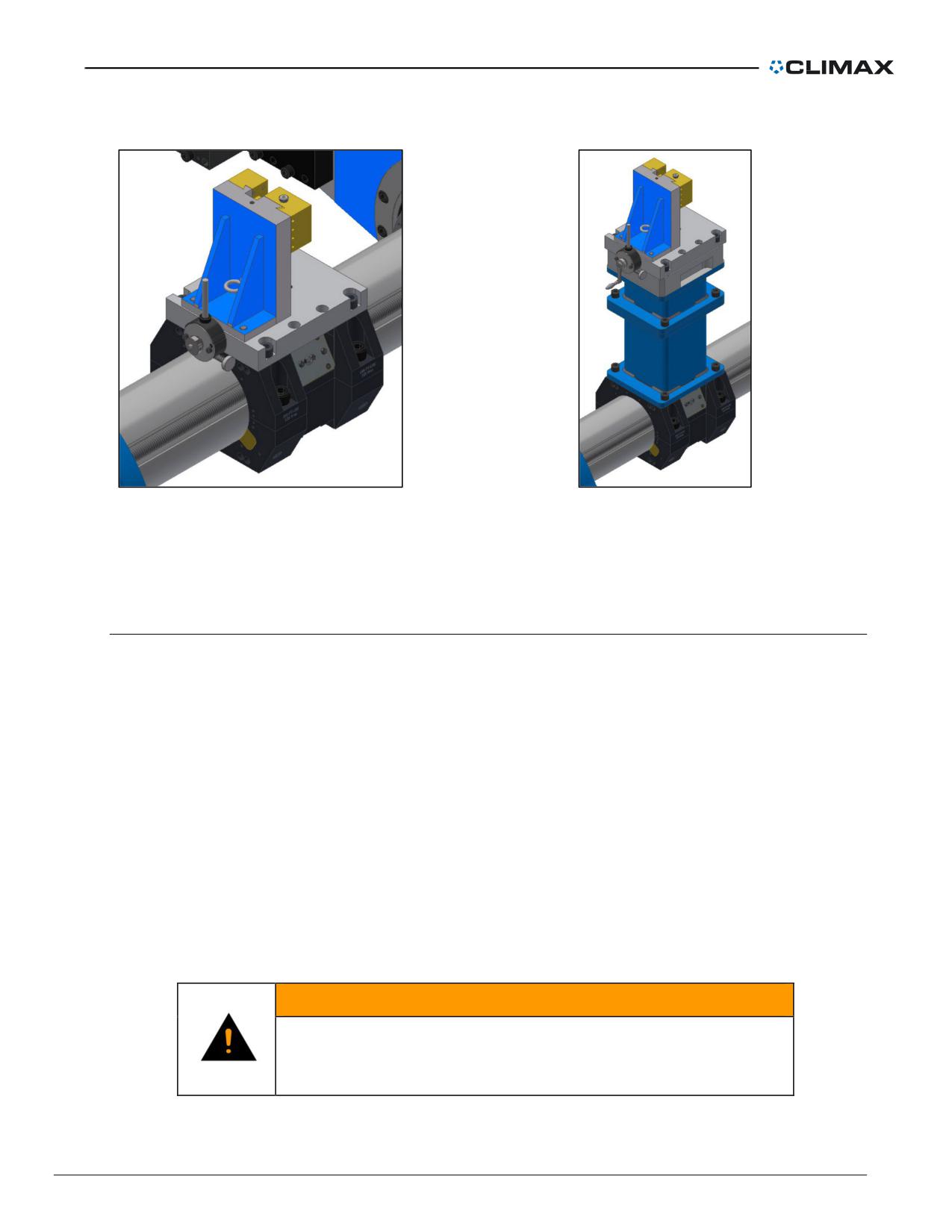
Figure 27. Facing head mounted directly to the tool
Figure 28. Facing head mounted with spacers to the
carrier
tool carrier
The facing head may mount directly to the tool carrier, or with spacers from the boring head stack
blocks as shown above.
Facing head radial feed
Radial feed is either manual or automatic. When the lid on the radial feed box is away from the
boring bar, the facing head will feed away from the center of the bar.
Setup
1. Select and assemble the appropriate configuration of spacers based on the
desired range, as specified in Table 5 on page 41.
2. Select the appropriate feed tools based on the following:
a) If no spacers are being used (see Figure 27), use the straight crank
handle and feed engagement knob to make manual adjustments and
engage the auto feed (see Figure 30 and Figure 31 on page 38).
b) If at least one spacer is being used (see Figure 28), use the feed box
crank to make manual adjustments and engage the auto feed. The feed
box crank is a combination tool that remains attached to the facing head
while in operation (see Figure 32 on page 38).
WARNING
Do not use the feed box crank if there are no spacers in the
configuration. This may damage the machine or the
workpiece if operated while attached.
P/N 57064, Rev. 9
Page 37
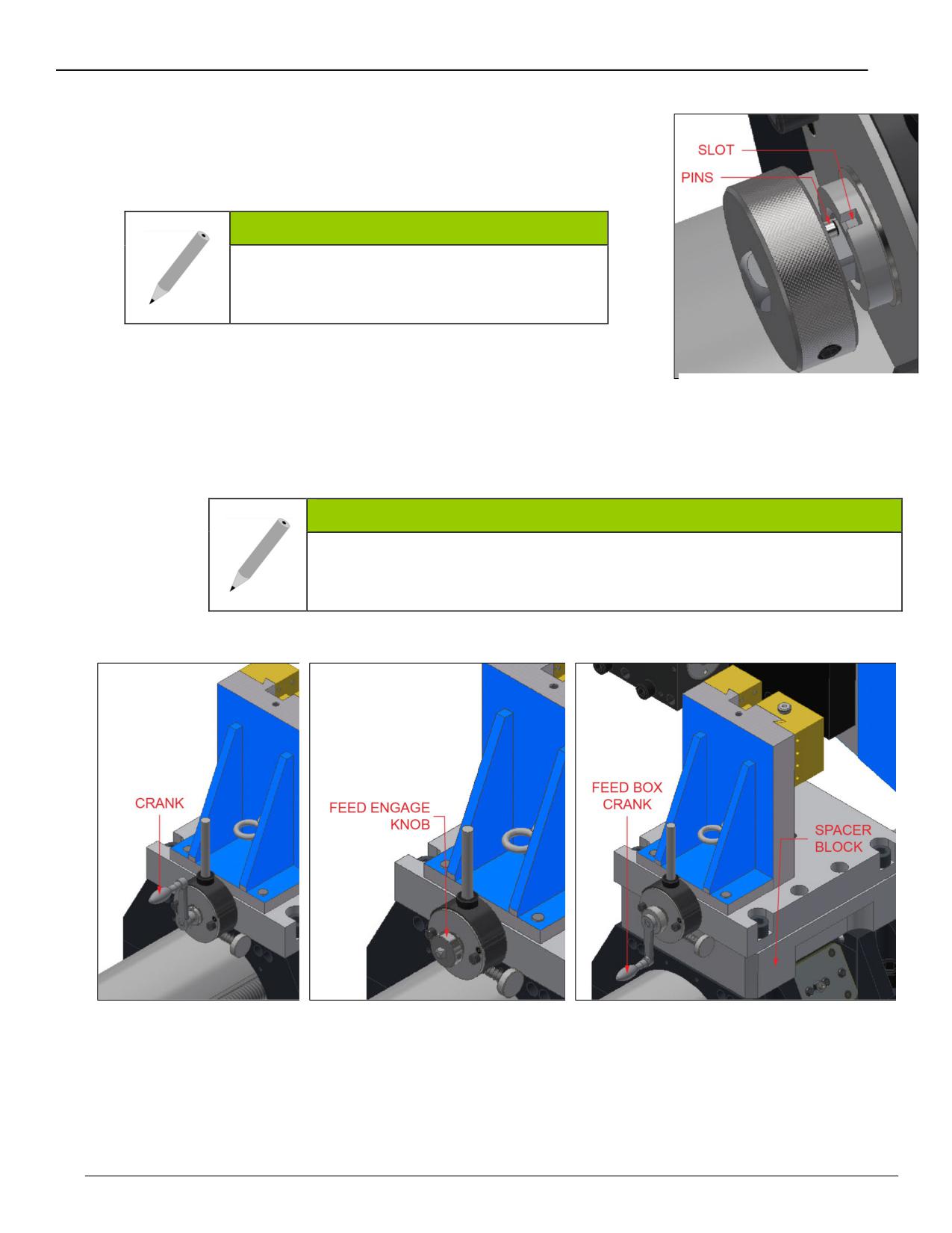
To manually feed the facing head
1. Disengage the feed box crank. The pins should
be retracted from the carrier feed ratchet slots
(see Figure 29).
NOTE
If the facing head is assembled without
spacers, remove the feed engagement knob
and mount the straight crank handle.
2. Turn the crank handle clockwise to feed the tool
Figure 29. Crank pins
out away from the center of the bar. Turn
disengaged
counter-clockwise to feed the tool in toward the
center of the bar. At the maximum recommended
torque rod angle of 15°, the automatic radial feed is infinitely variable up to
0.008" (0.2 mm) per trip.
NOTE
If the facing head is assembled without spacers, the straight crank
handle cannot turn a full revolution without striking the bar. Remove
and reattach as needed in order to complete each revolution.
Figure 30. Facing head
Figure 31. Facing head directly
Figure 32. Facing head mounted on
directly mounted with
mounted with feed engagement
spacers with feed box crank attached
straight crank handle
knob attached
attached
Page 38
BB8100 Operating Manual
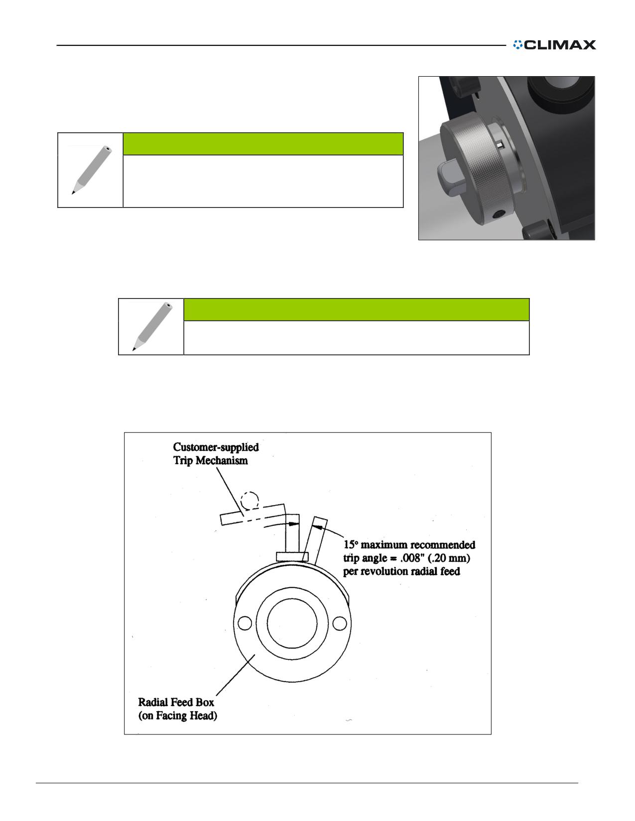
To automatically feed the facing head
Engage the feed box crank handle. Push the pins firmly into the
carrier feed ratchet slots (see Figure 33).
NOTE
If the facing head is assembled without spacers,
first remove the straight crank handle, then mount
and engage the feed engagement knob.
To activate the feed ratchet, provide a trip mechanism for the steel
rod. Set the trip to move the rod no more than 15°. If a radial feed
Figure 33. Crank pins engaged
of more than 0.008" (0.2 mm) per revolution is desired, use multiple
trip mechanisms.
NOTE
CLIMAX recommends a maximum trip of 15o.
To set the radial feed rate to less than 0.008" (0.2 mm) per revolution, move the trip mechanism
away from the center of the radial feed box. To increase the feed rate, move the trip mechanism
toward the center of the radial feed box.
Figure 34. Radial feed trip mechanism
P/N 57064, Rev. 9
Page 39
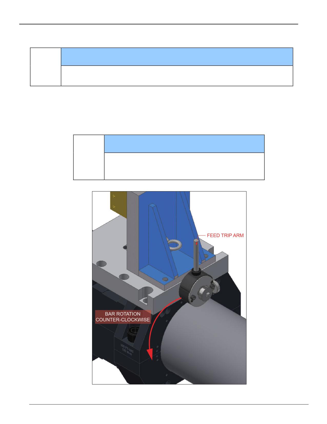
The feed trip arm must be tripped rotating clockwise relative to the feed box housing.
NOTICE
Actuating the feed trip arm in the opposite direction will result in machine
!
damage.
Use the feed trip arm according to the following principles:
• When the feed trip arm is oriented away from the boring bar, operate the bar in the
counter-clockwise direction (feed is radially in to out).
• When the feed trip arm is oriented toward the boring bar, operate the bar in the
clockwise direction (feed is radially out to in).
NOTICE
The trip arm must be facing away from the boring bar
!
when directly mounted to the tool carrier to ensure
clearance for the boring bar.
Figure 35. Feed trip arm and bar rotation
Page 40
BB8100 Operating Manual
Table 5 shows the facing range for the 5" (127 mm) travel head (P/N 21115).
Table 5. Facing Range for the 5" (127 mm) travel head (P/N 21115)
NUMBER OF BLOCKS REQUIRED FOR
THE THICKNESS SHOWN
USE 4.5" (114
RANGE
MM) SHCS
2.95"
5.9"
11.8"
(75 mm)
(150 mm)
(300 mm)
20.8-30.8"
0
0
0
No
(528.32-782.32 mm)
26.7-36.7"
1
0
0
Yes
(678.18-932.18 mm)
32.6--42.6"
0
1
0
No
(828.04-1,082.04 mm)
38.5--48.5"
1
1
0
Yes
(977.9-1,231.9 mm)
44.4--54.4"
0
0
1
No
(1,127.76-1,381.76 mm)
50.3--60.3"
1
0
1
Yes
(1,277.62-1,531.62 mm)
56.2--66.2"
0
1
1
No
(1,427.48-1,681.48 mm)
62.1--72.1"
1
1
1
Yes
(1,577.34-1,831.34 mm)
NOTICE
The facing ranges shown for these tables are calculated
!
with the tool feed radially out.
P/N 57064, Rev. 9
Page 41
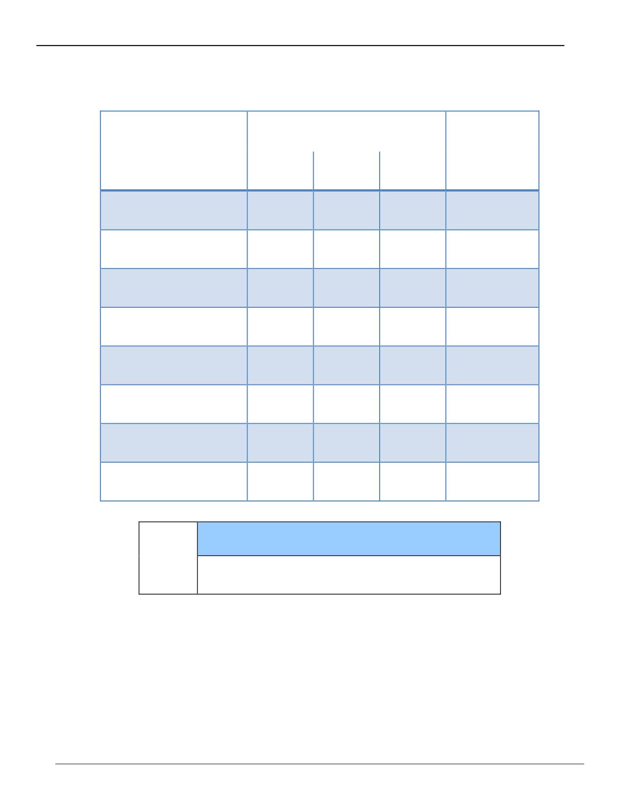
Table 6 shows the facing range for the 8" (203 mm) travel head (P/N 38654).
Table 6. Facing range for the 8" (203 mm) travel head (P/N 38654)
NUMBER OF BLOCKS REQUIRED FOR
THE THICKNESS SHOWN
USE 4.5" (114
RANGE
MM) SHCS
2.95"
5.9"
11.8"
(75 mm)
(150 mm)
(300 mm)
20.8-36.8"
0
0
0
No
(528.32-934.72 mm)
26.7-42.7"
1
0
0
Yes
(678.18-1,084.58 mm)
32.6--48.6"
0
1
0
No
(828.04-1,234.44 mm)
38.5--54.5"
1
1
0
Yes
(977.9-1,384.3 mm)
44.4--60.4"
0
0
1
No
(1,127.76-1,534.16 mm)
50.3--66.3"
1
0
1
Yes
(1,277.62-1,684.02 mm)
56.2--72.2"
0
1
1
No
(1,427.48-1,833.88 mm)
62.1--78.1"
1
1
1
Yes
(1,577.34-1,983.74 mm)
NOTICE
The facing ranges shown for these tables are calculated
!
with the tool feed radially out.
Page 42
BB8100 Operating Manual
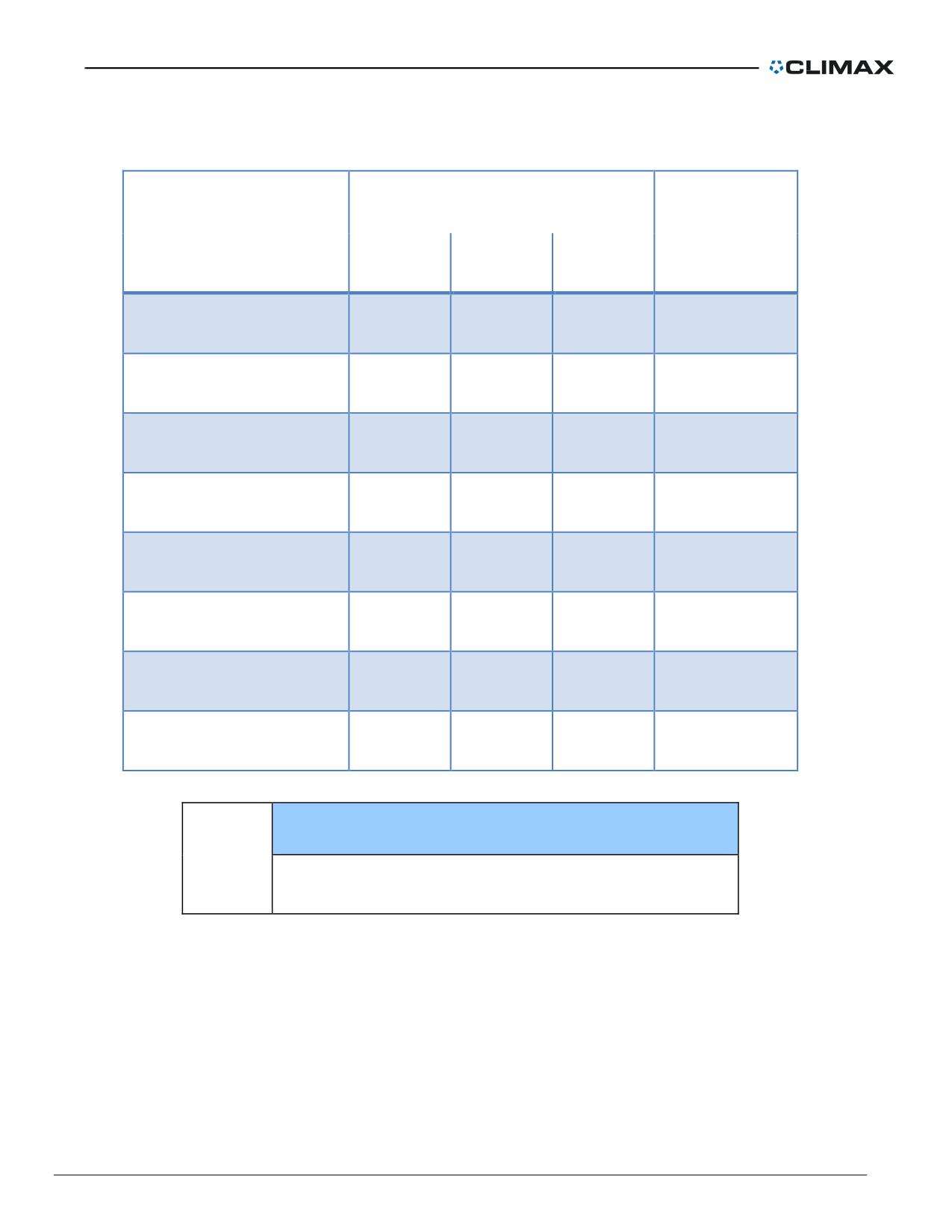
Table 7 shows the facing range for the 12" (305 mm) travel head (P/N 22359).
Table 7. Facing range for the 12" (305 mm) travel head (P/N 22359)
NUMBER OF BLOCKS REQUIRED FOR
THE THICKNESS SHOWN
USE 4.5" (114
RANGE
MM) SHCS
2.95"
5.9"
11.8"
(75 mm)
(150 mm)
(300 mm)
20.8-44.8"
0
0
0
No
(528.32-1,137.92 mm)
26.7-50.7"
1
0
0
Yes
(678.18-1,287.78 mm)
32.6--56.6"
0
1
0
No
(828.04-1,437.64 mm)
38.5--62.5"
1
1
0
Yes
(977.9-1,587.5 mm)
44.4--68.4"
0
0
1
No
(1,127.76-1,737.36 mm)
50.3--74.3"
1
0
1
Yes
(1,277.62-1,887.22 mm)
56.2--80.2"
0
1
1
No
(1,427.48-2,037.08 mm)
62.1--86.1"
1
1
1
Yes
(1,577.34-2,186.94 mm)
NOTICE
The facing ranges shown for these tables are calculated
!
with the tool feed radially out.
P/N 57064, Rev. 9
Page 43
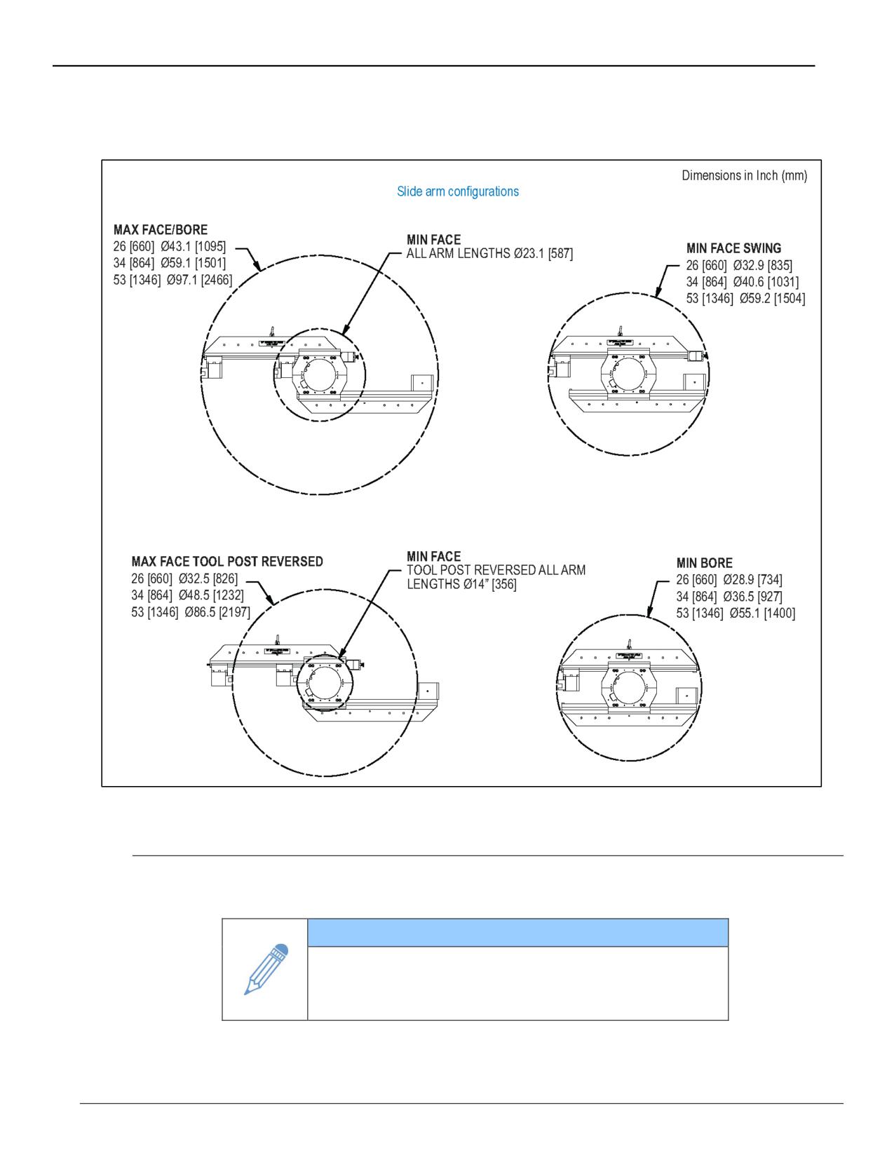
Installing the facing slide arm onto the tool carrier
Figure 36. Facing slide arm dimensions
Install the slide arm onto the tool carrier
1. Using a device such as a crane, place arm onto tool carrier flush with carrier
surface as shown.
IMPORTANT
Always use the lifting eyes when lifting the arms. The
rotating lifting eyes provide the flexibility and safety
during setup operations.
2. Secure arm with the clamp bars (P/N 54551) with 3/4-16 x 2 screws (P/N
28757) - four per clamp bar and torque to 100 ft-lbs (135 Nm).
Page 44
BB8100 Operating Manual
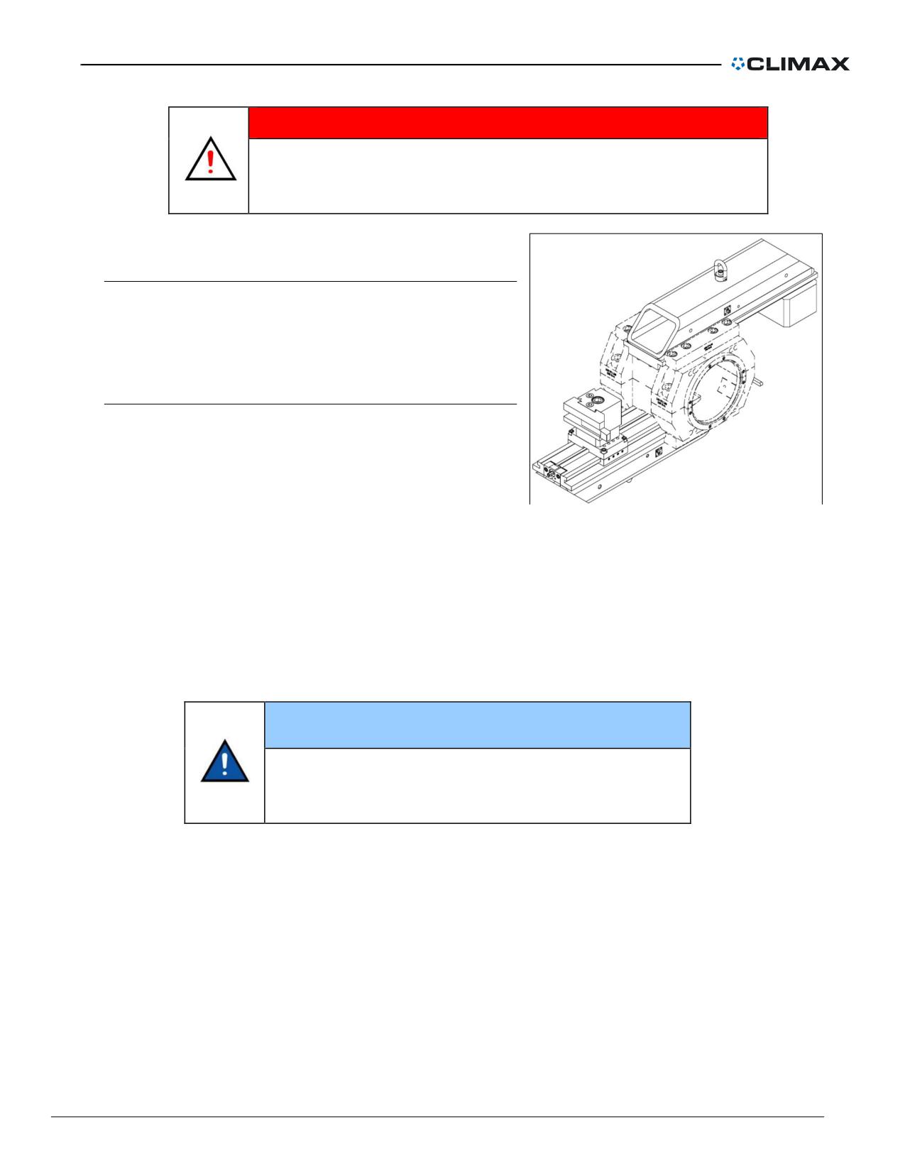
DANGER
Failure to properly torque the four 3/4-16 x 2 SHCS (P/N 28757) to
150 ft-lb (210 Nm) can result in unexpected slippage of the tool
arm which can result in injury or be fatal.
Adjusting the tool carrier for
perpendicularity
The tool carrier is equipped with four set screws
that allow you to adjust the slide arm
perpendicularity if required.
Feedbox assembly
Mount and secure the feedbox with adapter plate
(P/N 54867), as shown in Figure 37.
Figure 37. Facing slide arm with feedbox
and adapter plate
Install the counterweight arm onto the tool carrier
1. Rotate the tool carrier on the bar to allow the counterweight arm to be
mounted on the receiving surface of the tool carrier.
2. Attach the lifting eye onto counterweight arm and install arm
IMPORTANT
Always use the lifting eyes when lifting the arms. The
rotating lifting eyes provide the flexibility and safety
during setup operations.
3. Using a lifting device such as a crane, lift the counterweight assembly to the
arm. Fasten the counterweight assembly to the arm using the 7/8-14 x 1-1/2
(P/N 53049).
Note that you can position the counterweight itself anywhere along the arm as needed to
balance the assembly.
P/N 57064, Rev. 9
Page 45
Hydraulic power preparation and connection
CAUTION
Before using the power unit, check pump rotation by jogging
the motor. The motor should rotate in the direction indicated
by the arrow on the pump.
1. Turn the power unit OFF.
2. Check that all fittings are clean.
3. Connect the hydraulic lines from the hydraulic motor to the power unit.
4. Jog the motor to see which direction the bar is rotating. Do the following to
reverse the bar rotation:
a) Turn off the hydraulic power unit.
b) Switch the hoses at the motor end.
5. Adjust the speed of the bar rotation by pressing the HIGH/LOW VOLUME
CONTROL button on the pendant.
CAUTION
To avoid damaging the pump and voiding the warranty,
connect the hydraulic motor to the power unit pump before
turning on the power unit.
Page 46
BB8100 Operating Manual
OPERATION
Pre-start checks
WARNING
Rotating machinery can cause serious injury. Turn off and lock
out power before making pre-start checks.
Before operating the portable boring bar
1. Tie down the rotational drive unit torque arms and the axial feed unit stop rod.
2. Check that all cutters are sharp and in good condition.
3. Secure fixed machine parts, including the tool carrier, tool head and cutting
tool. Check that moving parts move freely.
4. Check that the hydraulic power unit is OFF.
5. Check that the power unit wiring matches the electric power source. Plug the
power unit into a grounded outlet.
6. Check the power unit reservoir level. Fill the reservoir to above the red bar
with Mobil DTE-24 anti-wear hydraulic oil. Check that the power unit is level.
7. Clean the hydraulic hoses and fittings before connecting them.
8. Check that the electric pump motor on the hydraulic power unit is turning the
same way as the arrow on the case.
9. If the machine is setup in a vertical orientation, the clamp collars must be
installed for safety.
P/N 57064, Rev. 9
Page 47
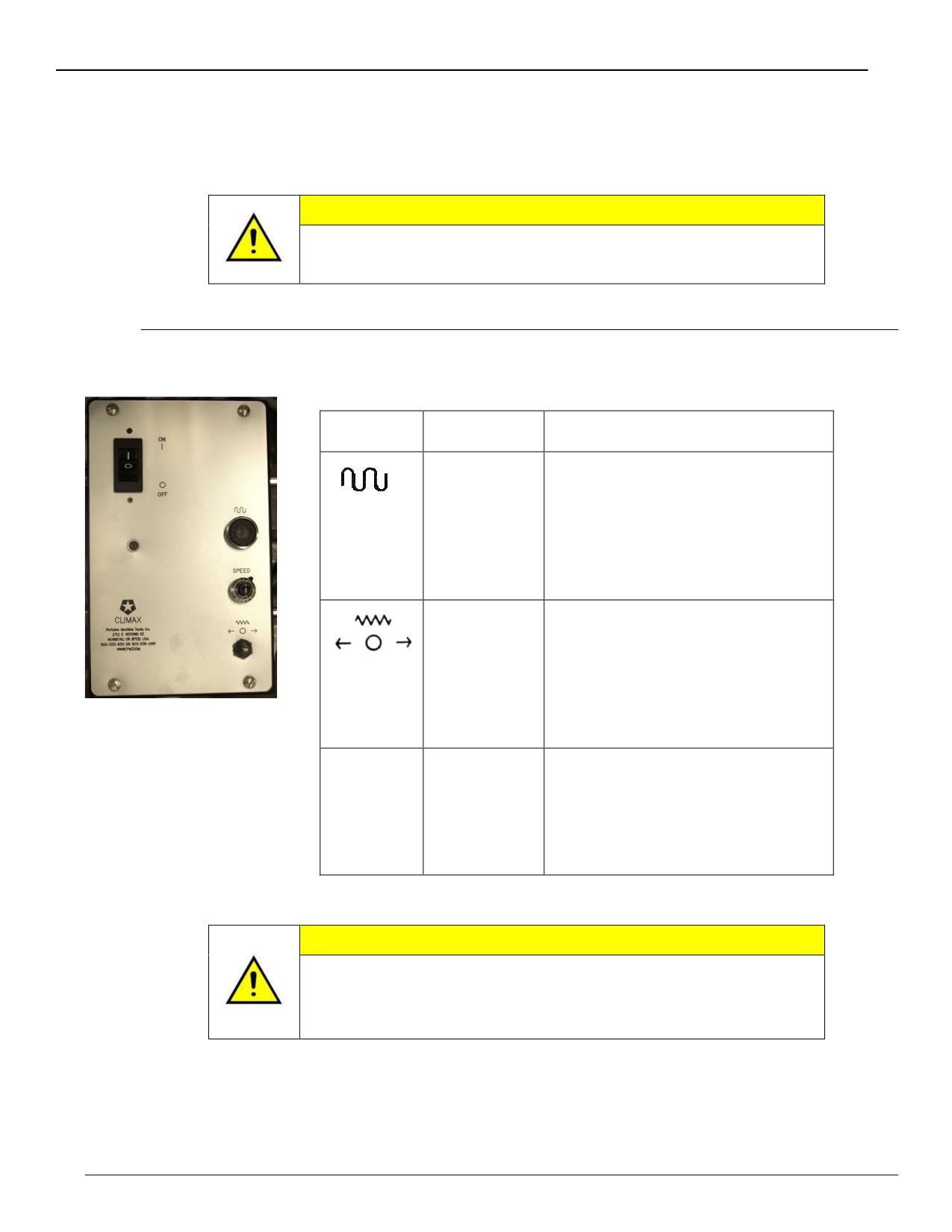
Using the remote pendants
Operator controls for the machine are located on the remote pendants, described below.
CAUTION
The bar rotation and the axial feed are independent of each
other. Check that the feed is OFF when the bar is not running.
Feed pendant
The following is a description of the Feed Pendant controls:
Symbol
Feature
Description
Feed speed
A momentary button which
override
overrides the feed rate
potentiometer and runs the axial
power feed at maximum rate,
regardless of the potentiometer
setting.
Feed Fwd /
A 3-position selector switch that
Rev
determines the direction of axial
feed. In neutral, power feed is
disengaged. The feed rate can
be adjusted or reversed during
Figure 38. Feedbox
operation.
pendant
Speed
The Feed potentiometer controls
the axial feed rate.
Counterclockwise decreases the
feed rate; clockwise increases
the feed rate.
CAUTION
Damage to the cutter, the boring machine and your work piece
may occur if the bar rotation is stopped while the power feed is
engaged and the cutting tool is in contact with the workpiece.
Page 48
BB8100 Operating Manual
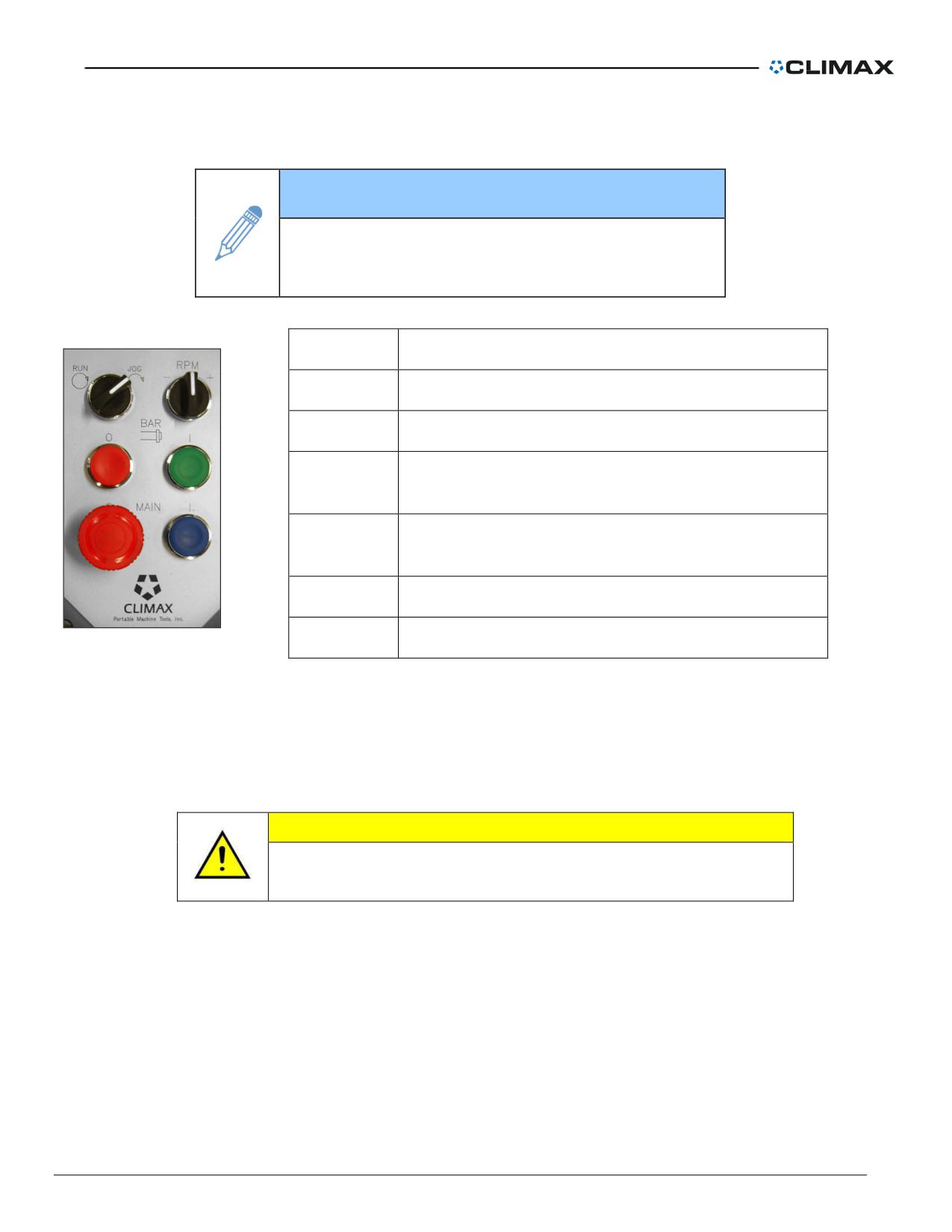
HPU pendant
TIP
Additional information about the HPU function,
construction, and maintenance schedule can be
found in the HPU manual.
Feature
Description
Run/Jog
Runs or jogs the hydraulic power unit.
RPM
Increases or decreases the rotational speed.
Bar Off
Turns off the hydraulic power unit.
(red)
Bar On
Turns on the hydraulic power unit.
(green)
Off (red)
Turns off the electric motor.
On (blue)
Turns on the electric motor.
Figure 39. HPU pendant
Manual override (electrical feed only)
The manual override consists of 2-position gear lever that disengages the electric drive from the
boring bar. When disengaged, a hand-drill can be installed for manual rapid operation. When the
gear box is in the manual override position, the pendant functions are not active.
CAUTION
Do not force the shift lever to engage. Forceful engagement
can damage the mechanical override mechanism.
To move the tool carrier rapidly, shift the feed lever on the top of the gearbox to the back position.
With a socket on the hexagon shaft, run with an electric drill or speed wrench. To re-engage the
feed, remove the socket, turn the feed on slow, and shift the feed lever to the forward position.
Clamp collars
The collars (P/N 40708) are made in matching sets and must be used to secure the bar when the
machine is in the vertical orientation.
P/N 57064, Rev. 9
Page 49
DANGER
To prevent the bar from sliding through the support bearings, or
falling, use the two clamp collars provided in the tool kit when
using the boring bar in a vertical orientation. Torque to 100 ft.-lbs
(13.6 Nm).
Starting the machine
WARNING
To avoid injury from flying chips or loud noise, wear
eye and ear protection while operating the machine.
1. Turn off and lock out the hydraulic power unit.
If boring:
a) Set the feed direction on the axial feed assembly. See “Setting the
feed direction” on page 29.
b) Set the feed rate on the axial feed assembly. See “Setting the feed
rate” on page 29.
If facing:
a) Set the feed direction on the axial feed assembly to NEUTRAL. See
“Setting the feed direction”
b) Adjust the automatic trip mechanism on the facing head. See “Facing
head radial feed”.
2. Press POWER UNITON at the hydraulic power unit pendant.
3. Press PRESSURE START at the pendant.
4. Adjust the bar rotation speed using the HIGH/LOW VOLUME CONTROL
knob on the pendant.
5. As cutting begins, lubricate the work piece and cutting tool with plenty of
cutting oil. Apply cutting oil with a squirt can or use an automatic mister.
Stopping the machine
WARNING
In case of emergency press POWER UNIT OFF on the
control pendant.
1. Press POWER UNIT OFF at the pendant to stop the power unit.
2. After all parts of the machine has stopped, use a brush to remove chips.
Page 50
BB8100 Operating Manual
WARNING
To avoid serious personal injury from flying chips, do not use
compressed air to remove chips.
3. If you will be machining the work piece again, see “Repetitive machining”. If
you are done machining, see “Disassembly”.
Repetitive machining
1. Reverse the tool head feed direction.
2. Manually or automatically feed the tool head back to where it started cutting.
3. Re-sharpen the tool bit or replace the carbide inserts, if necessary.
4. Using a dial indicator reset the tool bit cutting depth. Maximum recommended
cutting depth is 0.125" (3 mm).
5. Operate the boring bar as described in “Starting the machine” on page 50.
Disassembly
WARNING
The boring bar is not hardened. To prevent damage to the bar, do
not strike it against the bearing supports or the work piece.
Standard disassembly
1. Turn off and lock out the hydraulic power unit.
2. Unplug electrical cords and cables.
3. Disconnect the hydraulic hoses from the motor.
4. Remove the cutting tool from the tool head.
5. Remove the tool head and tool carrier.
6. Remove the axial feed assembly from the bar.
7. Securely support the boring bar, bearing supports, and rotational drive
assembly with hoists
8. If the rotational drive assembly is between bearing support assemblies,
remove one support first:
a) Loosen the bearing cartridge.
b) Loosen the support from the workpiece.
c) Remove the support from the bar.
9. Securing the rotational drive assembly with a hoist, loosen the eight socket-
head cap screws in the rotational drive assembly.
10. Push the locking rings out by screwing in the four setscrews.
P/N 57064, Rev. 9
Page 51
11. Remove one lock ring.
12. Remove the drive key.
13. Carefully slide the rotational drive assembly off the bar.
14. Loosen the bearing cartridges.
15. Remove the boring bar.
16. Remove all remaining bearing supports from the workpiece.
Alternative disassembly
In some cases, it is better to remove the bearings before removing the bar.
1. Turn off and lock out the hydraulic power unit.
2. Unplug all electric cords and cables, including the rotational drive assembly
fan cord.
3. Disconnect the hydraulic hoses from the motor.
4. Remove the tool bit or carbide cartridge from the tool head.
5. Remove the tool head and tool carrier.
6. Securely support the boring bar, bearing supports, and rotational drive
assembly with hoists.
7. Remove the axial feed assembly from the bar.
8. If the rotational drive assembly is between the bearing support assemblies,
remove one support first:
9. Loosen the bearing cartridge.
10. Loosen the bearing support from the workpiece.
11. Remove the bearing support from the bar.
12. Support the rotational drive assembly with a hoist. Loosen the eight socket-
head cap screws. Push out the locking rings by screwing in the four
setscrews. Remove one lock ring. Remove the drive key. Carefully slide the
rotational drive assembly off the bar.
13. Loosen the taper bore adapters in the bearings by doing the following:
a) Loosen the 3/8"-24 set screws (SSSFP).
b) Tighten the 1/4"-28 HHCS until the taper unseats.
c) Loosen and remove the 1/4"-28 HHCS. Note that the HHCS screws pull
the lock nut and taper out of the bearing mount.
d) Loosen and remove the taper nut.
14. Place a clean wooden “crib” in the bottom of the bore.
15. Remove the bearing supports from the workpiece.
16. Slide the bar out of the bore using the crib.
Page 52
BB8100 Operating Manual
MAINTENANCE
Recommended lubricants
LUBRICANT
BRAND
WHERE USED
Gear grease
UNOBA EP #0
Bearing cartridges
Rotation drive oil
Mobil SHC 634 Synthetic
Gear box cone drives
Light oil
LPS 2
Unpainted surfaces
Cutting oil
UNOCAL KOOLKUT
Tool bits, work piece
Way oil
Mobil VACTRA Heavy-Medium Way Oil
Dovetail ways
Hydraulic oil
Mobil DTE-24 Anti-wear hydraulic oil
Hydraulic power unit and motor
CAUTION
To avoid damage to the machine, only use recommended
lubricants.
Boring bar/leadscrew
Clean the leadscrew and boring bar frequently during operation. Keep chips away from the
leadscrew threads. Lubricate the leadscrew periodically with light oil to ensure smooth travel of
the rotational drive assembly. Before storage, lightly oil the bar to prevent rusting. Lightly grease
the leadscrew. Do not grease areas where chips can accumulate in the oils.
Axial feed assembly
Under normal conditions, the axial feed assembly is maintenance-free.
Rotational drive assembly
Under normal use, change the drive oil in the rotational drive gearbox every 500 hours with Mobil
600W Super Cylinder Oil (AGMA 7 Compounded) or equivalent.
Do the following to fill the gear box:
1. Using the lifting eye, set the gearbox upright. Secure the rotational drive unit
so it cannot move.
2. Remove the fill plug and oil plug.
3. Fill the rotational drive until oil overflows the oil plug hole.
4. Replace the oil plug.
5. Add one more quart of oil through the fill plug hole.
P/N 57064, Rev. 9
Page 53
6. Replace the fill plug.
Bearing support assembly
Under normal conditions, bearing assemblies are lubricated for life.
Before storage, lightly oil the assemblies to prevent rusting.
Tool head assembly
Manual boring head assembly
Lightly oil all parts to prevent rusting.
Manual facing head assembly
Before use and frequently during operation, lubricate the tool head carrier with way oil through the
grease fitting. Brush chips from the leadscrew frequently to prevent thread damage. Lightly oil the
leadscrew periodically to ensure smooth travel of the tool holder. When changing tool holders,
apply way oil to the dovetail ways.
Tool carrier
Lightly oil all parts with JET LUBE 550 to prevent rusting.
Hydraulic power unit and motor
General hydraulic system
After 72 hours of operation, do the following:
1. Replace the filter cartridge
2. Check the heat exchanger for leaks. Repair any leaks before running the
power unit.
3. Clean the filler/breather.
Hydraulic motor
The hydraulic motor is maintenance-free. Fluid passing through the motor lubricates internal
moving parts. To ensure long life and dependable operation, use high-quality clean hydraulic fluid
as described in “Hydraulic filter and fluid” on page 54.
Hydraulic filter and fluid
Though the hydraulic power unit requires little maintenance, changing the filter and fluid is
required for proper operation. Initially, change the filter after 72 hours of operation to remove
Page 54
BB8100 Operating Manual
impurities from the system. From then on, replace the filter every 150-200 hours. Use a high-
quality 10-micron industrial-grade filter. If the filtering system has a change-warning gage, replace
the filter whenever the gage indicates. Clean hydraulic fluid will help keep the power unit and
motor running properly.
The hydraulic fluid should be changed:
• When the oil becomes contaminated
• When the power unit is operated at high temperatures for a long time
• Every two years
Hydraulic fluid level should not drop below the red bar on the fluid level/temperature gage. Add
only filtered fluid to the system. Should hydraulic fluid leak out, do not put it back in the reservoir.
Use Mobil DTE-24 anti-wear hydraulic oil or equivalent. Recommended oil operating temperature
is 150o F (66 o C).
WARNING
Connect the hydraulic motor to the power unit pump before turning on
the power unit. Failure to do so will damage the pump and void all
warranties.
P/N 57064, Rev. 9
Page 55

Troubleshooting
SYMPTOM
SOLUTION
Check the feed direction is set to the desired setting.
Clean the leadscrew.
Axial feed unit will not
Check that the feed rate is not too low.
advance the bar
Check that the axial feed unit is securely mounted to the
end of the bar.
Re-sharpen the tool bit or replace the carbide inserts.
Adjust the feed rate.
Chatter
Increase or decrease the hydraulic motor speed.
Change the cutter depth.
Tighten all clamps and hardware.
Machine is unstable
Provide additional support.
Check that the hydraulic power unit is turned on.
Check that the pump motor is turning in the correct
direction.
Rotational drive unit
will not rotate
Check the oil level in the power unit.
Check that the speed control is open.
Check the hydraulic hose connections.
Feeds in wrong
Check the handle position on the axial feed unit.
direction
Check the fluid level. Add more fluid if necessary.
Hydraulic power unit
Check that the pump motor is turning in the correct
fails to deliver fluid
direction.
Check hydraulic connections for plugs or leaks.
Check that the power unit and electrical supply are
compatible.
Hydraulic power unit
motor does not run
Check that the power unit is plugged in.
Check for faulty wiring.
Page 56
BB8100 Operating Manual
STORAGE
Proper storage of Model BB8100 Portable Boring Bar will prevent undue deterioration or damage
of the machine.
1. Before storing, wipe the machine down with solvent to remove grease, metal
chips, and moisture.
2. To prevent rusting, spray with a moisture-displacement material such as Jet-
Lube 550 for short-term storage, LPS 3 for long-term storage.
3. Store the machine in the container provided.
4. Place desiccant bags or vapor wrap around the machine to absorb moisture.
P/N 57064, Rev. 9
Page 57
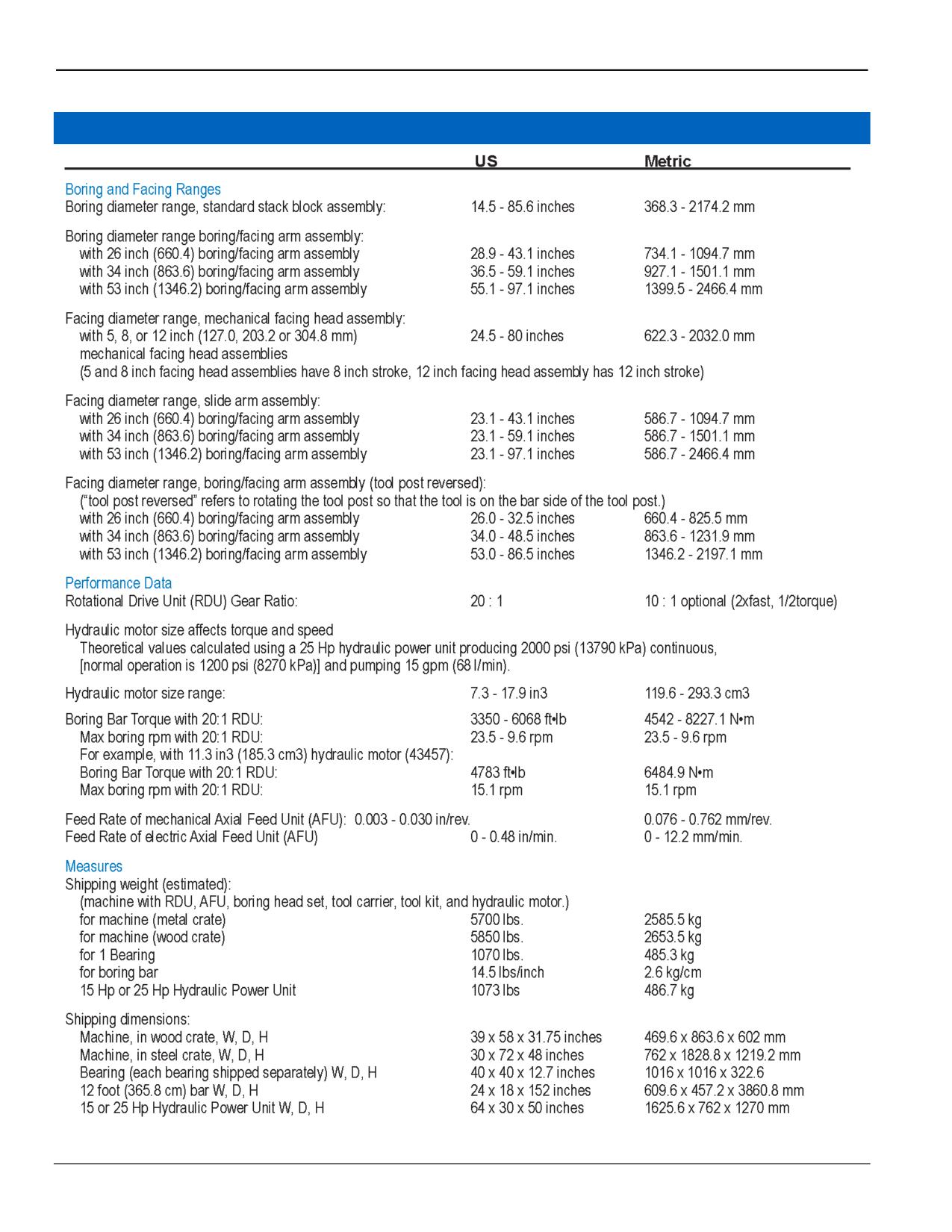
SPECIFICATIONS
Page 58
BB8100 Operating Manual
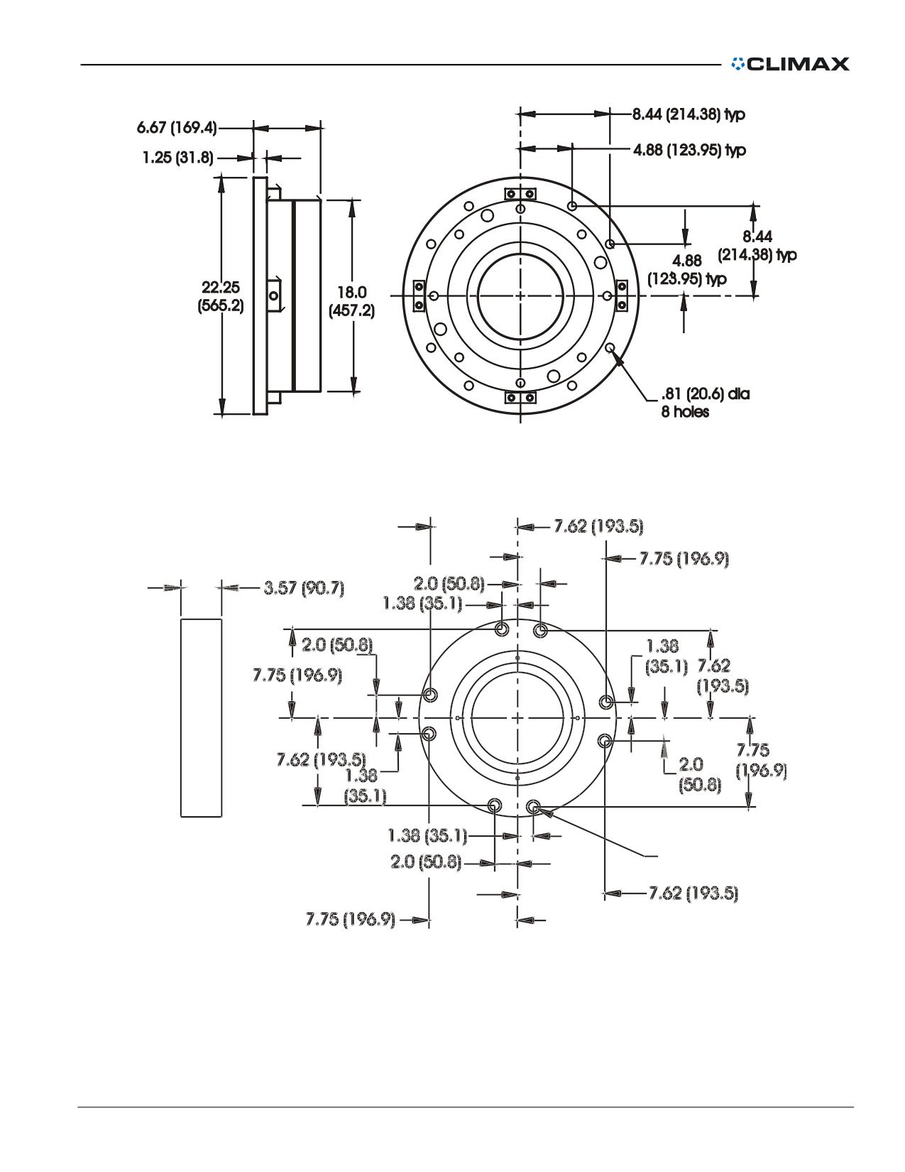
Figure 40. Dimensions of the self-aligning bearing assembly without spider
Figure 41. Dimensions of the non-aligning bearing assembly without spider
P/N 57064, Rev. 9
Page 59
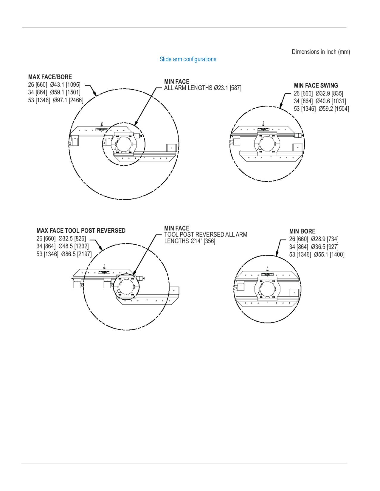
Page 60
BB8100 Operating Manual
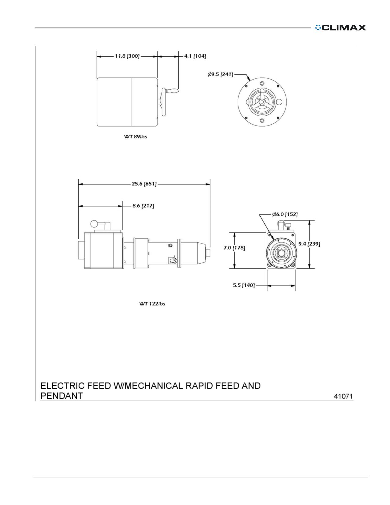
P/N 57064, Rev. 9
Page 61
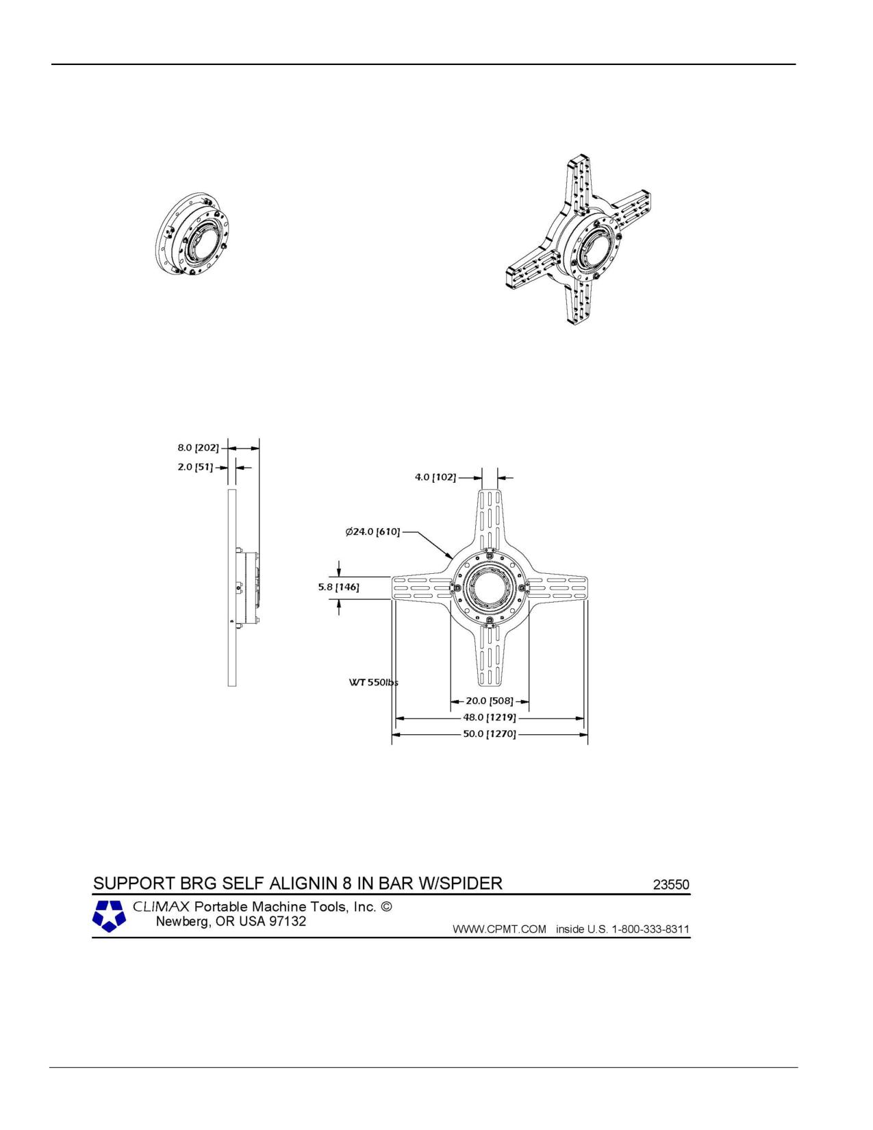
Page 62
BB8100 Operating Manual
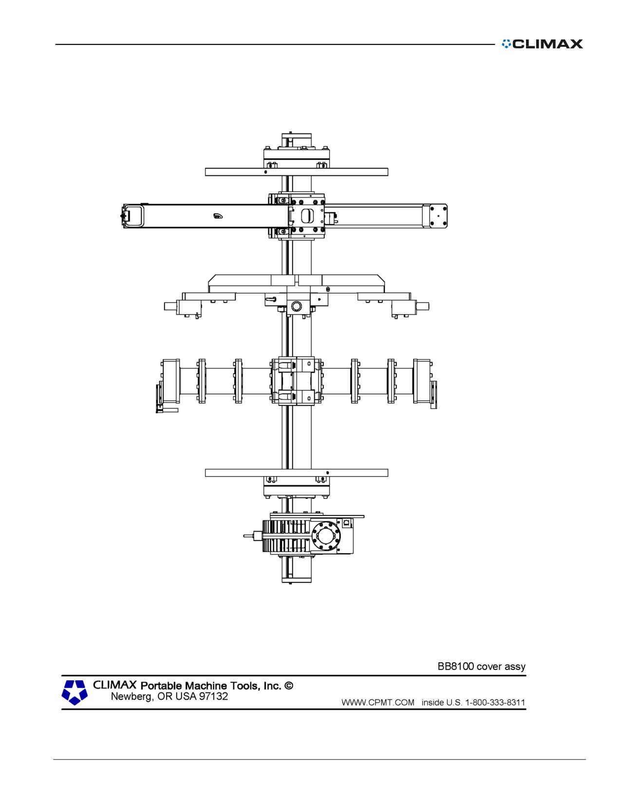
P/N 57064, Rev. 9
Page 63
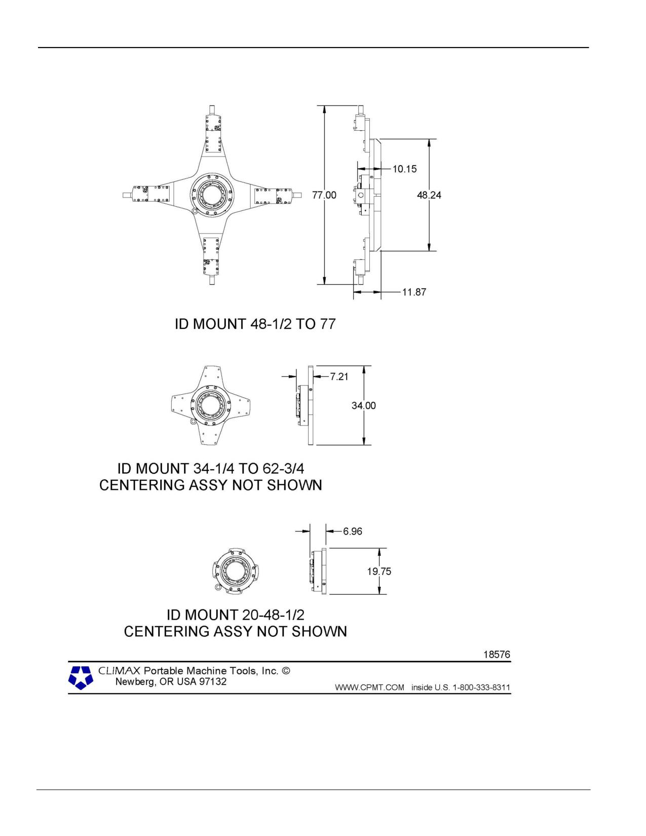
Page 64
BB8100 Operating Manual
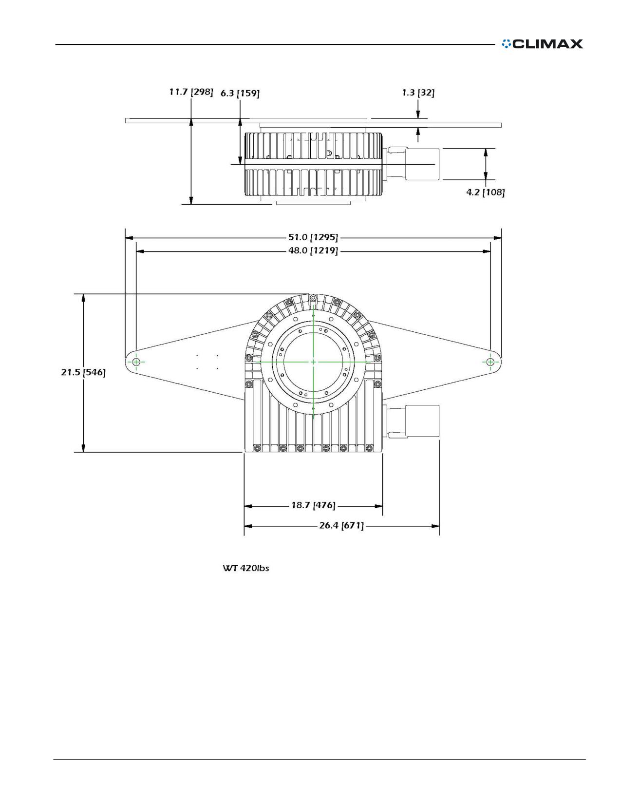
P/N 57064, Rev. 9
Page 65
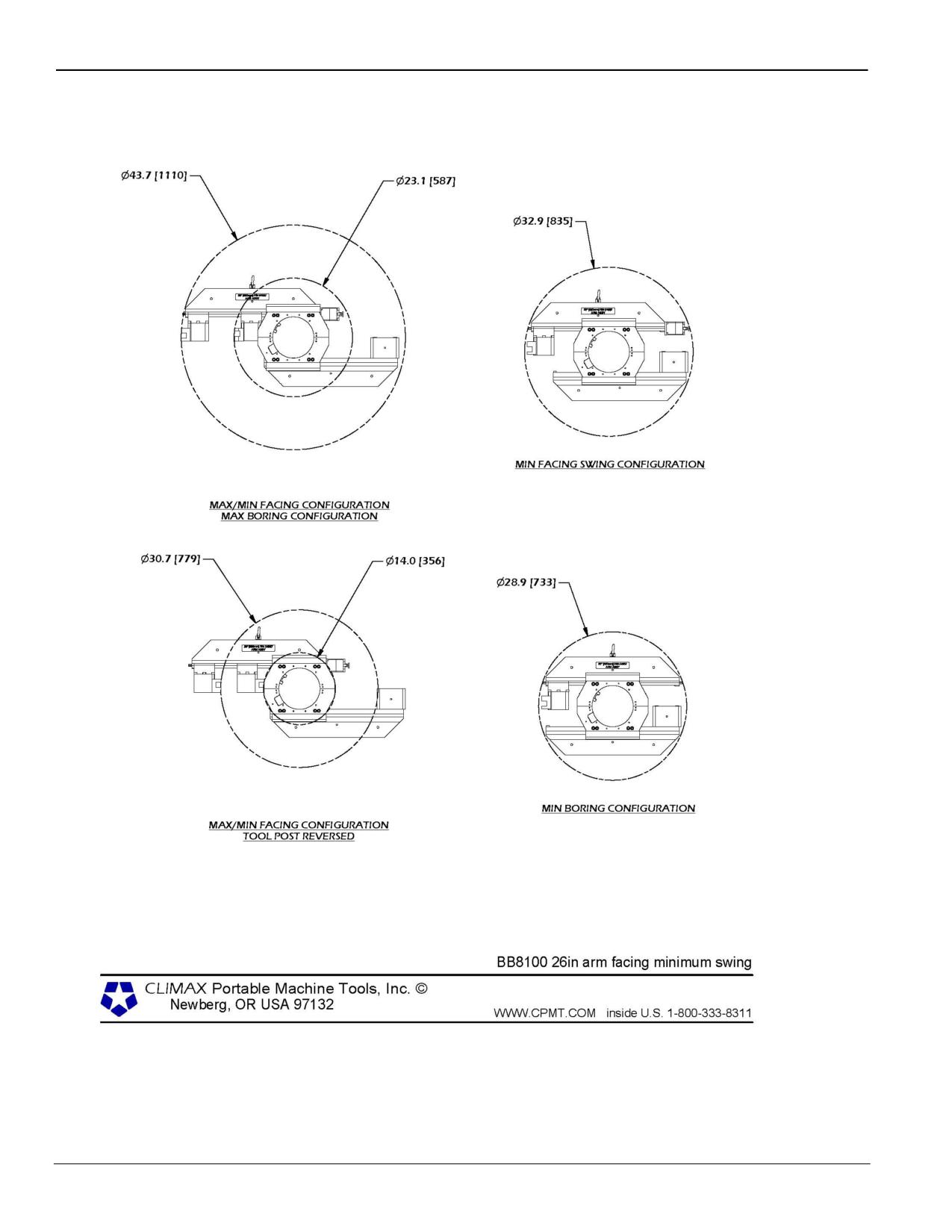
Page 66
BB8100 Operating Manual
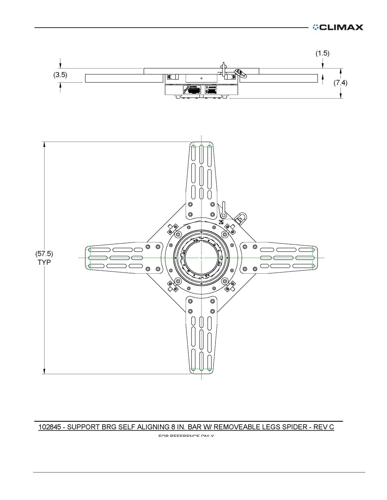
P/N 57064, Rev. 9
Page 67
TOOL KIT AND SPARE PARTS
Table 8. Tool kit (P/N 54264)
P/N
DESCRIPTION
QTY
UOM
13052
WRENCH HEX BIT SOCKET 1/2 X 1/2 (KB)
1
Piece
14526
WRENCH SPEED HANDLE 1/2 DRIVE
1
Piece
14650
WRENCH END 1/2 COMBINATION LONG (KB)
1
Piece
15367
WRENCH STRAP 1-3/4 WIDE X 48 LONG
1
Piece
16793
WRENCH SOCKET 1/2 8 PT X 1/2 DRIVE
1
Piece
17437
WRENCH IMPACT SPANNER
1
Piece
19700
CONTAINER SHIPPING FLAT ROOF 20 X 8.75 X 10.5
1
Piece
20869
WRENCH HEX SET 5/64 TO 3/4 15 PIECES
1
Piece
40708
CLAMP COLLAR 8 ID TWO PIECE W/ SET SCREWS
2
Piece
57064
MANUAL INSTRUCTION BB8100
1
Piece
71729
WRENCH HEX 3/32 3.25 T-HANDLE
1
Piece
71730
WRENCH HEX 1/8 3.75 T-HANDLE
1
Piece
71731
WRENCH HEX 3/16 4.5 T-HANDLE
1
Piece
71732
WRENCH HEX 7/64 6.25 T-HANDLE
1
Piece
The listed spare parts are most frequently required due to wear, loss, or damage. To avoid
unscheduled down time, you may want to stock these items.
Table 9. Spare parts
PART NO.
DESCRIPTION
QTY
WHERE USED
17575
Nut leadscrew bearing adj.
1
11739
Thrust washer
2
10137
Thrust bearing
1
8" boring bar assembly
13179
Needle bearing
1
17616
O-ring
1
17617
O-ring
1
17448
4-5/8" Jaw
2
17449
8" Jaw
2
ID-mount bearing assembly
17700
Screw 5/8-18 x 5-1/2 SHCS
2
Page 68
BB8100 Operating Manual
PART NO.
DESCRIPTION
QTY
WHERE USED
11823
Thrust washer
2
10538
Thrust bearing
1
10858
Gear worm
1
17447
Crank shaft
1
10217
3/16 square key
1
14274
Thrust Washer
2
13174
Thrust bearing
1
17508
Worm nut
1
17520
Screw assembly jam feed
1
21053
Thrust washer
1
17007
Thrust washer
1
17507
Worm gear nut
1
10612
Snap ring
1
11739
Thrust washer
1
11158
5/8" Lifting eye
1
15208
5/8 Flat Washer
12
20390
Screw 5/8-11 x 6 SHCS
4
11696
Screw 1/2-13 x 3 SHCS
8
End-mount bearing assembly
26100
Screw 3/8-24 x 2 HHCS
8
26101
Screw 1/4-28 x 2 HHCS
6
20911
Screw 3/4-10 x 1-1/2 SSSFP
4
20133
Boring head cartridge size 10
1
15210
Screw 6-32 x 5/8 SHCS
2
15196
Clamp insert - size 10
2
15195
Chip breaker - size 10
2
Manual boring head assembly
17822
Carbide insert
6
23069
Tool holder - positive rake
1
23141
Chip breaker T3AE
2
18155
Carbide insert TPG 321 KC-850
10
13175
Thrust washer
2
13174
Thrust bearing
2
Manual Facing Head Assembly
14274
Thrust washer
2
P/N 57064, Rev. 9
Page 69

PART NO.
DESCRIPTION
QTY
WHERE USED
11165
Thrust washer
4
10538
Thrust bearing
2
10532
Bearing roller clutch
1
22357
Carbide insert SPU
20
23046
Chip breaker
6
25807
Filter element
1
Hydraulic power unit
14420
Hydraulic fluid
5 gal.
23662
Axial feed bar fuse
1
Mechanical Unit Axial feed
assembly Electric Unit
14303
Stop rod
1
17825
Carrier nut
1
10453
Screw 3/8-16 x 1-1/4 SHCS
2
17864
Carrier key
1
Tool carrier
10191
Screw 3/8-16 x 1 SHCS
2
11678
Screw 10-32 x 3/8 BHSCS
16
Page 70
BB8100 Operating Manual
EXPLODED VIEWS AND PARTS
The following diagrams and parts lists are for your reference purposes only. The machine
Limited Warranty is void if the machine has been tampered with by anyone who has not
been authorized in writing by CLIMAX to perform service on the machine.
P/N 57064, Rev. 9
Page 71