Boring Machine Operation & Safety Instruction Manual (2009)
Boring Machine
Operation & Safety
Instruction Manual
WARNING
Unsafe use of this equipment could result in serious injury or death. This manual con-
tains important instructions for the safe operation and recommended maintenance of
your earth boring machine. All who operate the boring machine must carefully read
and understand this manual before starting the machine. Keep this manual available
both as a reminder for your experienced operator and as a training aid for your new
staff. Replacement manuals are available by calling American Augers.
Forward
Boring Machine Operators Manual
Introduction
Forward
INTRODUCTION
American Augers was established in 1970 to
tion of all models of American Augers Boring
provide a full line of modern equipment for the
Machines.
trenchless excavation construction industry. The
Boring machine specifications are subject to
company is organized in three product divisions
change without notice or obligation to retrofit
to serve the full range of trenchless technology.
units already in the field. This manual will be
American Augers is the division producing the
constantly updated to remain current with new
leading line of Horizontal Earth Boring
operations. Please call if there are areas requir-
Machines. We are proud of our equipment and
ing further explanation or instruction.
the job it can do. We encourage you to call us
The materials may not be reproduced in
for any and all your boring needs. Every effort
whole or in part without the express written per-
has been made to adequately cover the opera-
mission of American Augers Inc.
Manual Part Number BMNG10000
Released July 2009 Revision 06
Refer to the Safety Awareness Program in this manual before attempting to operate this machine
Page 2
Boring Machine Operators Manual
Forward
Machine Serial Number Locations
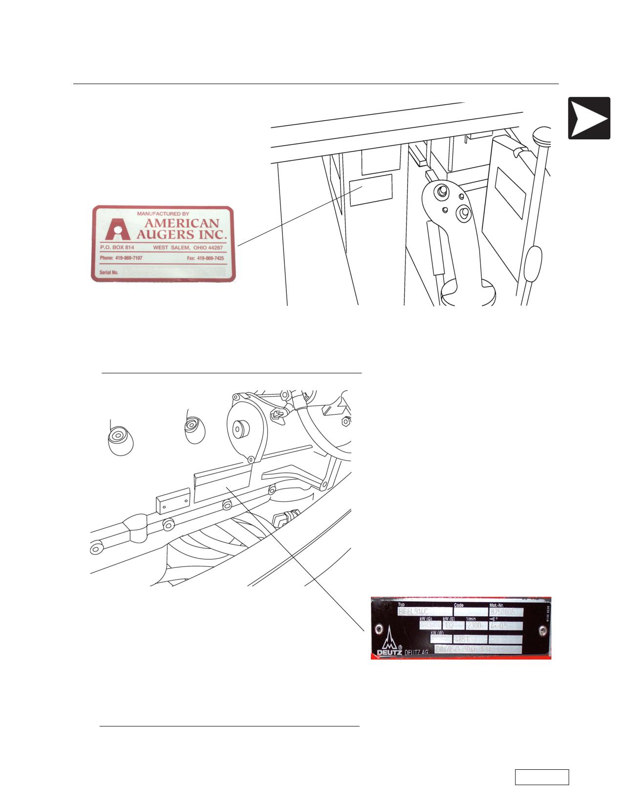
Location of Machine Serial Number Plate
Machine Serial Number
Location of Deutz Engine Serial Number Plate
Deutz Engine Serial Number
Refer to the Safety Awareness Program in this manual before attempting to operate this machine
Page 3
Forward
Boring Machine Operators Manual
Machine Serial Number Locations
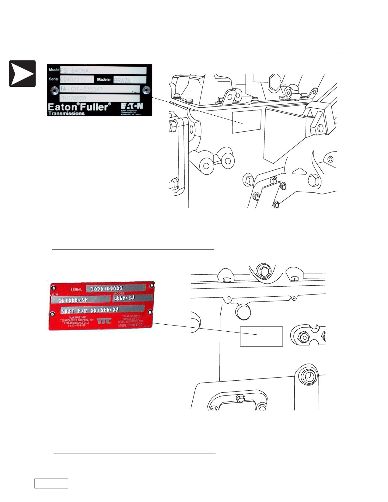
Location of Eaton Transmission Serial Number Plate
Eaton Transmission Serial Number
Location of TTC Transmission Serial Number Plate
TTC Transmission Serial Number
Refer to the Safety Awareness Program in this manual before attempting to operate this machine
Page 4
Boring Machine Operators Manual
Forward
Machine Serial Number Locations
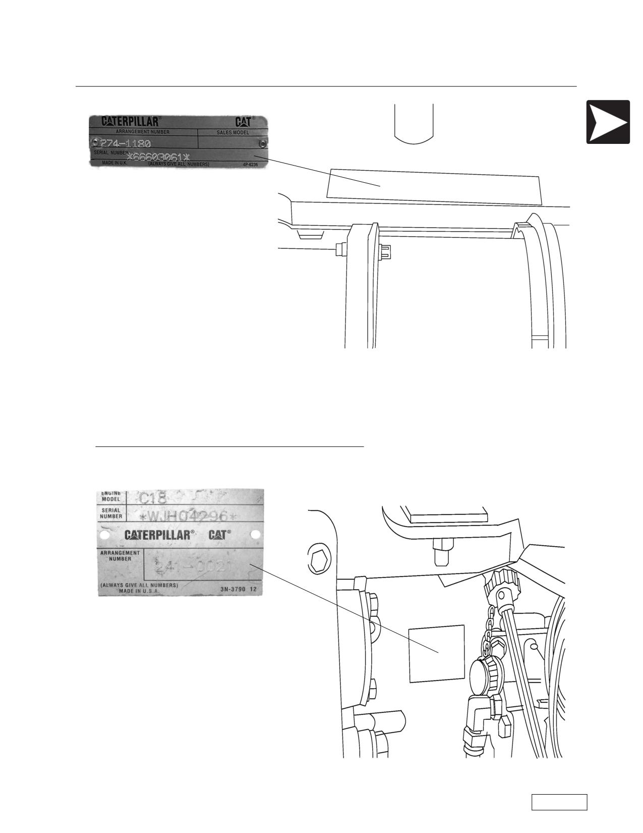
Location of Caterpillar Engine Serial Number Plate
Caterpillar Engine Serial Number
Refer to the Safety Awareness Program in this manual before attempting to operate this machine
Page 5
Forward
Boring Machine Operators Manual
Machine Serial Number Locations
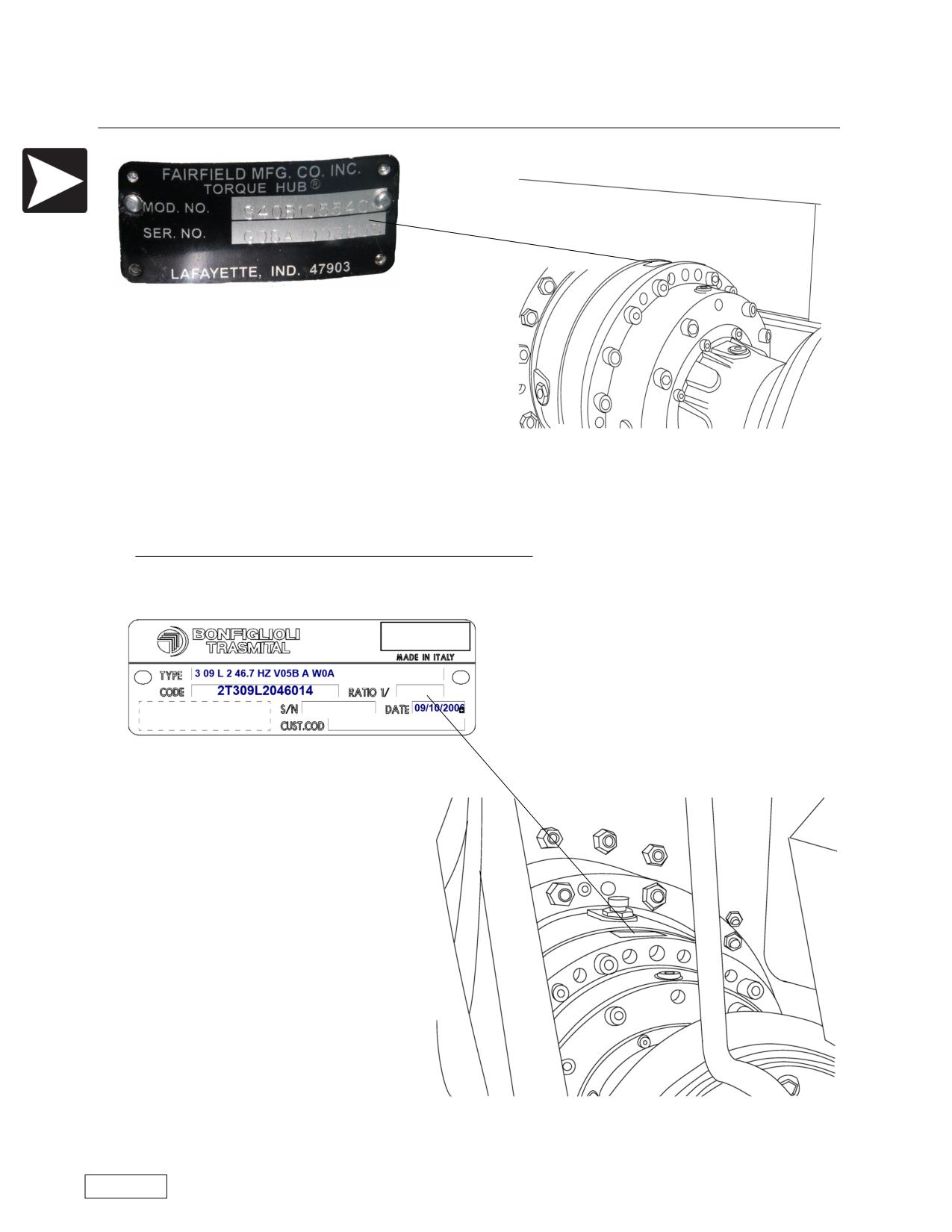
Location of Planetary Gearbox Serial Number Plate
Planetary Gearbox Serial Number
Refer to the Safety Awareness Program in this manual before attempting to operate this machine
Page 6
Boring Machine Operators Manual
Forward
Revision Record
Revision to Manual
Revision Number
Description of Change
Date
00
Total rewrite and update. Includes old style and "NG" models
8/2/2007
01
Updated and reformatted.
9/30/2008
02
Added text about different methods of banding and updated
11/7/2008
specifications
03
Revised text about Preventing Machine Upset, Page 27
2/4/2009
04
Revised Detail Controls for 36/42-600NG and 48/54-900NG Boring
2/11/2009
Machines in accordance with ECN's
05
Updated Thrust Charts in the Appendix in accordance with ECN
4/24/2009
06
Added instructions about setting gear backlash
7/8/2009
Refer to the Safety Awareness Program in this manual before attempting to operate this machine
Page 7
Forward
Boring Machine Operators Manual
Revision Record
Revision to Manual, Continued
Revision Number
Description of Change
Date
Refer to the Safety Awareness Program in this manual before attempting to operate this machine
Page 8
Boring Machine Operators Manual
Forward
To The Owner
To The Owner
Thank you for your purchase of the American Augers Auger Boring Machine.
This manual contains important information that will help you and your crew set up and safely operate
the Auger Boring Machine. DO NOT operate or permit anyone to operate or service this machine until you
have read this Manual. Use only trained operators who have demonstrated the ability to operate and service
this machine correctly and safely.
DO NOT use this machine for any application or purpose other than those described in this Manual.
Consult the American Augers factory for changes, additions, or modifications that may be required for this
machine to comply with various safety requirements. Unauthorized modifications could cause serious injury
or death. Anyone making such unauthorized modifications is responsible for the consequences.
Make sure this Manual is complete and in good condition. Contact the American Augers factory to
obtain additional manuals and for further information about/or assistance with your machine. Your American
Augers factory has approved service parts and technicians with special training that know the best methods
of repair and maintenance for your machine.
Refer to the Safety Awareness Program in this manual before attempting to operate this machine
Page 9

Forward
Boring Machine Operators Manual
NOTICE
Before using this manual, familiarize yourself with
the Description Of Components (page 15) and the
Glossary of Terms.
American Augers encourages use
of the One-Call system.
NOTICE
Horizontal earth boring machines have a num-
ber of hazards unique to their operation. A
series of safety alert decals are provided on
American Augers’ horizontal earth boring
machines to alert the operator to hazards of the
machines. The Safety Section explains the haz-
ard alert signs.
PERFORMANCE
Actual machine, accessory, and component performance, capacity, and results can be adversely
affected by or vary with such factors, as environmental conditions, weather, failing to exercise
proper maintenance, machine functionality not being utilized within suggested operating
levels, mechanical or component substitutions that may alter factory standards, operator
experience, or other unforeseen limitations not previously listed.
Refer to the Safety Awareness Program in this manual before attempting to operate this machine
Page 10
Operators Manual
Table of Contents
Table of Contents
Forward
2
Introduction
2
Machine Serial Number Locations
3
Revision Record
7
To The Owner
9
Overview
15
Boring Machine Components
15
Location of Components, NG Models
17
General Information
19
Operation and Maintenance Manual
19
Ownership of Information
19
Manufacturer Identification Data
19
Machine Identification Data
19
Qualification of Personnel
19
EC-Declaration of Conformity
20
Use of Personal Protective Equipment
20
Legal Disclaimer
20
Purpose of Machine
20
Pit Preparation
20
Ambient Conditions
20
Features of Transport
20
Machine Handling Procedures
20
Warranty
21
Request for Service/Support
21
Warranty and Service for Diesel Engine
21
Instruction Manual
21
Safety Information
23
Safety Awareness Program
23
Basic Safety Guidelines
24
Safety Alerts
29
Safety Alerts
29
Refer to the Safety Awareness Program in this manual before attempting to operate this machine
Page 11
Table of Contents
Operators Manual
Site Preparation
41
Guidelines For Use Of Boring Machines
41
Setting and Aligning the Track
42
Detailed Controls
43
Safety Switches and Tethered Deadman Switch
43
24/30-150 Boring Machine Controls
44
36/42-440NG Boring Machine Controls
46
36/42-600NG Boring Machine Controls prior to S/N NG3660002841208
48
36/42-600NG Boring Machine Controls, S/N NG3660002841208 and higher
50
42-600NG Boring Machine Controls
52
48/54-900NG Boring Machine Controls prior to S/N NG48549002281208
54
48/54-900NG Boring Machine Controls S/N NG48549002281208 and higher
56
60-1200NG Boring Machine Controls
58
72-1200NG Boring Machine Controls
60
Installing the Boring Machine
64
Assembly of Split-Design Machines
64
Before Operating The Engine
66
Quik Tran
67
Preparation of Casing
68
Constructing the Steering Head
69
Installing the Lead Casing and Auger in the Pit
75
Case Boring Procedure
76
Collaring
77
Preparing the Exit Pit
80
Removing the Auger at the Completion of the Bore
81
Storage and Transportation
83
Minimum Storage Space Required
83
Storage
84
Transport
84
Preliminary Operations for Transportation of the Machine
84
Refer to the Safety Awareness Program in this manual before attempting to operate this machine
Page 12
Operator’s Manual
Table of Contents
Lifting the Boring Machine
84
Boring Machine Weights
86
General Maintenance
87
The Value of a Preventive Maintenance Program
87
Qualification of the Technician
88
Welding
88
Cleaning
88
Scheduled Maintenance
90
Maintenance Schedule
90
10 Hour Inspection and Maintenance
91
50 Hour Inspection and Maintenance
93
500 Hour Inspection and Maintenance
94
1000 Hour Inspection and Maintenance
95
After Each Use
96
Specifications
97
24/30-150 Specifications
97
36/42-440 Specifications
98
36-600 Specifications
99
42-600 Specifications
100
48-900 Specifications
101
48/54-900 Specifications
102
60-1200 Specifications
103
72-1200 Specifications
104
Appendix
105
Appendix A: Boring Machine Force Charts
107
Appendix B: Entrance Pit
111
Appendix C: Ground Conditions Chart
112
Appendix D: Cutting Heads
113
Appendix E: Auger Weight Charts
114
Appendix F: Casing Weight Charts
116
Appendix G: Boring Machine Glossary of Terms
118
Limited Warranty
123
Refer to the Safety Awareness Program in this manual before attempting to operate this machine
Page 13
Table of Contents
Operators Manual
NOTES:
Refer to the Safety Awareness Program in this manual before attempting to operate this machine
Page 14
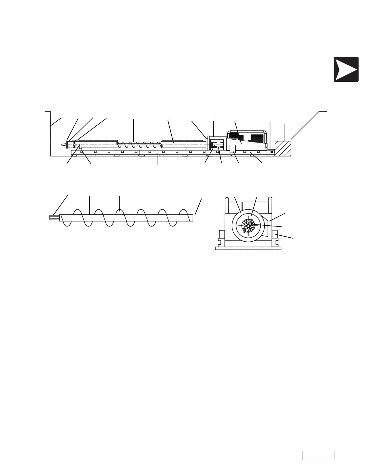
Boring Machine Operators Manual
Overview
Overview
Overview
Boring Machine Components
Current Design, NG Models
1
2
3
4
5
6
7
8
9
10
11
15
16
18
17
12
13
14
19
20
21
22
8
7
23
2
18
1) Pit Face
2) Cutting Head
3) Steering Head
4) Steering Knuckle
5) Auger
6) Casing
7) Casing Adapter
8) Casing Pusher
9) Boring Machine
10) Push Bar
11) Backstop
12) Saddle Adapter
13) Master Saddle
14) Extension Track
15) Drive Chuck (Front Drive)
16) Spoil Ejector
17) Master Track
18) Quik-Tran Drive
19) Male Hex Shank (Auger Shank)
20) Auger Tube
21) Auger Flite
22) Female Hex Bushing (Auger Bushing)
23) Spoil Ejector Door
Refer to the Safety Awareness Program in this manual before attempting to operate this machine
Page 15
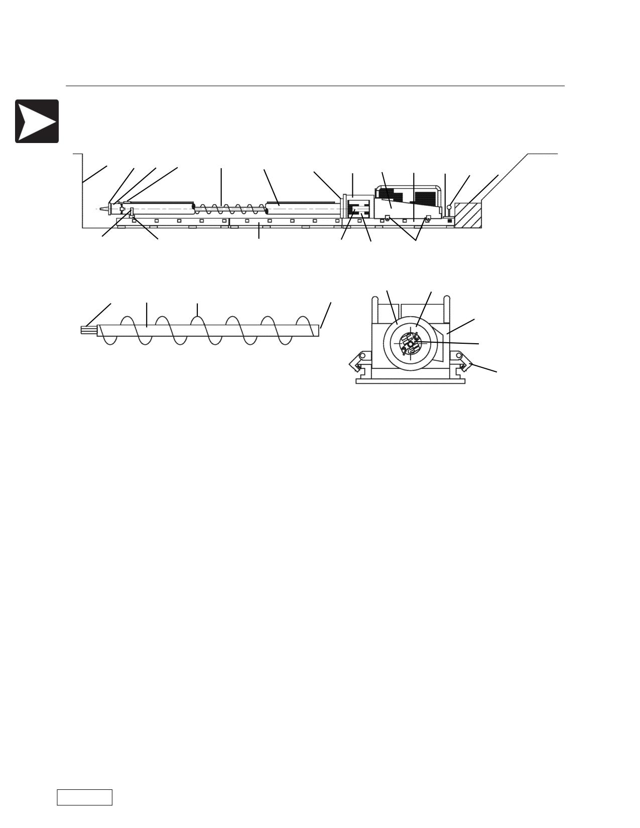
Overview
Boring Machine Operators Manual
Overview
Boring Machine Components (continued)
Pre NG Design
1
2
3
4
5
6
7
8
9
17
10
24
11
12
13
14
15
16
18
8
7
19
20
21
22
23
2
18
1) Pit Face
2) Cutting Head
3) Steering Head
4) Steering Knuckle
5) Auger
6) Casing
7) Casing Adapter
8) Casing Pusher
9) Boring Machine
10) Push Bar
11) Backstop
12) Saddle Adapter
13) Master Saddle
14) Extension Track
15) Drive Chuck (Front Drive)
16) Spoil Ejector
17) Master Track
18) Hook Rollers
19) Male Hex Shank (Auger Shank)
20) Auger Tube
21) Auger Flite
22) Female Hex Bushing (Auger Bushing)
23) Spoil Ejector Door
24) Brake
Refer to the Safety Awareness Program in this manual before attempting to operate this machine
Page 16
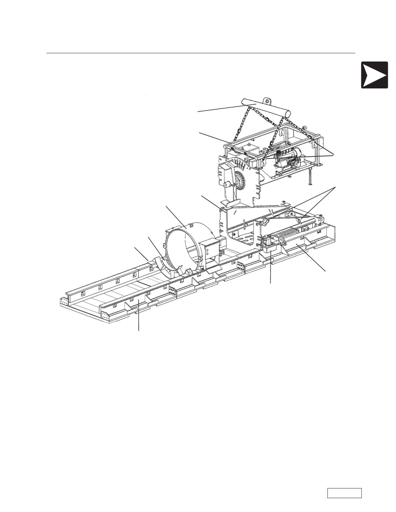
Boring Machine Operators Manual
Overview
Overview
Location of Components, NG Models
Illustration does not reflect actual hardware only the location of hardware on assembly.
4
1
2
3
6
5
10
9
7
11
8
1) Power Package - This portion of the machine contains the engine, clutch, transmission, and coupling
half. It also includes the fuel tank, hydraulic oil tank, filters, hydraulic pumps and operating controls
2) Indicates lift points for the power package only, using the sling provided by American Augers
3) Indicates lift points for the base unit.
4) The sling provided by American Augers.
5) Master Casing Pusher - Contains the spoil chamber, spoil door, and casing adapter, as needed for
smaller diameter casings.
6) Base Push Unit - Included in this section are the base frame unit, header wall, gearbox, final drive,
spoil paddles, chuck, thrust cylinders, push bar, operators station.
7) Master Track - This section of track is furnished with the machine, and is always used as the rear most
track section. It has a thrust plate bolted to the end of the track.
8) Extension Track - These are additional sections of track to be bolted to the master track and to each
other to allow installation of longer casing sections. Two sections of extension track along with the master
track are furnished with each machine.
9) Saddle - Rests on the track in front of the boring machine to carry casing and auger.
Refer to the Safety Awareness Program in this manual before attempting to operate this machine
Page 17
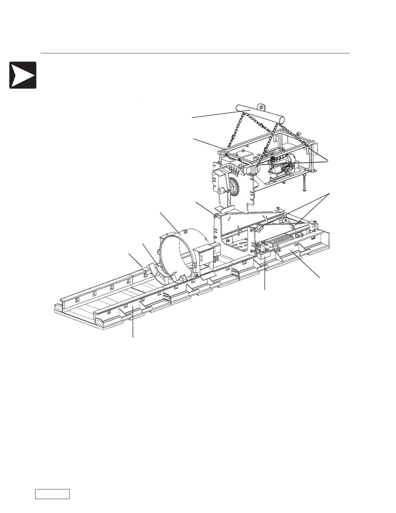
Overview
Boring Machine Operators Manual
Overview
10) Saddle Adapter - This may be mounted on the saddle to carry smaller casings than the machine
size.
11) Quik-Tran - Returns the boring machine to its starting position on the Master track. Normally there is
one Quik-Tran assembly on each side.
4
1
2
3
6
5
10
9
7
11
8
Refer to the Safety Awareness Program in this manual before attempting to operate this machine
Page 18
Boring Machine Operators Manual
Overview
General Information
Operation and Maintenance Manual
TITLE:
Boring Machines Operation & Safety Instruction Manual
EDITION:
2008
Part number:
BMNG10000
Operator
The operator must read and follow the manual.
Ownership of Information
American Augers, Inc. reserves all rights to the information in this manual.
The manual cannot be reproduced or photocopied in part or in whole without previous written authoriza-
tion from American Augers, Inc. The use of the manual is restricted to the customer who received it and only
for purposes of installation, use and maintenance of the relevant machine. American Augers declares that
the information contained in this manual fits the technical and safety specifications of the machine. American
Augers disclaims responsibility for direct or indirect damages to persons or property caused when the man-
ual or the machine are used in violation of the information contained herein.
The information contained in the manual refers only to the machine mentioned in Paragraph, MACHINE
IDENTIFICATION DATA. American Augers reserves the right to modify or improve the manual and the
machines without notice.
Manufacturer Identification Data
AMERICAN AUGERS, INC.
135 U.S. Rt. 42, P.O. Box 814
West Salem, Ohio 44287 USA
Tel. 419-869-7107 • Fax 419-869-7425
Web Site: www.americanaugers.com
Machine Identification Data
Type:
Auger Boring Machine
Model:
Various
Serial number:
All
Year of manufacture:
All
Location of identification plates: See illustrations on pages 3 through 6.
Qualification of Personnel
If skilled personnel operate the machine according to the advice and instructions supplied in the manual,
the machine will operate safely. All the operations of transport, use and maintenance must be carried out
only by skilled and authorized personnel, after studying and understanding the instructions supplied by the
manual.
NOTICE
American Augers disclaims any responsibility for damages to persons or property
caused by the operation of the machine by untrained personnel.
Refer to the Safety Awareness Program in this manual before attempting to operate this machine
Page 19
Overview
Boring Machine Operators Manual
General Information
EC-Declaration of Conformity
If required, the declaration of EC conformity is issued at consignment of the machine together with the
manual and the CE mark will be applied. EC conformity is not required in North America.
Use of Personal Protective Equipment
WARNING
If personal protective equipment is not used, serious injury or death of personnel
can occur.
The operator and all other personnel on the worksite should use proper protective equipment according
to their duties.
Legal Disclaimer
NOTICE
American Augers disclaims any responsibility for damages to persons or property
caused by the operation of the machine in violation of the instructions contained in
this manual.
Purpose of Machine
The machine was designed for the purpose of horizontal boring through the earth.
Pit Preparation
See the appendix for the pit preparation requirements.
Ambient Conditions
Temperature limits: 5°F and 105°F [-15°C and +40°C] (with oils and coolants recommended). For tem-
perature lower than 32°F [0°C] contact American Augers. For temperatures not included in the range 40°F
AND +5°F [-40°C AND -15°C] contact American Augers.
Relative humidity : 100%
Maximum altitude: 6500 ft [2000 m] above sea level
Atmospheric conditions should allow adequate visibility within the operating area.
The machine should not be operated when lightning is likely.
Features of Transport
The machine should be transported by a truck tractor, in accordance with local transportation laws.
Machine Handling Procedures
Use
For safety reasons, it is recommended only one person operates the controls. Other trained personnel
may work near the boring machine if they are wearing personal protective equipment.
Refer to the Safety Awareness Program in this manual before attempting to operate this machine
Page 20
Boring Machine Operators Manual
Overview
General Information
Maintenance
During maintenance, with the machine running, be especially cautious to ensure the safety of all person-
ell.
Warranty
General Conditions
Warranty is subject to the conditions specified in the warranty certificate.
Limitations of Warranty
The warranty for all the components purchased and not produced by American Augers directly are sub-
ject to the original warranty of suppliers/manufacturers and therefore defects in materials or workmanship
are considered valid only if they are recognized by the same suppliers/manufacturers. In particular the war-
ranty on the diesel engine is supplied by the diesel engine dealer in the area where the drill is sold.
Warranty Certificate
The warranty certificate is on the inside of the last page of this manual.
Request for Service/Support
For service support in or out of the warranty period, contact American Augers.
Provide model number, serial number of the machine, and working hours. The working hours can be
read from the hour meter display set into the tachometer. Or, where a Caterpillar engine is used, from the
hour meter in the Caterpillar engine display.
Warranty and Service for Diesel Engine
The local diesel engine dealer services the diesel engine. The diesel engine warranty is valid worldwide.
Only diesel engine dealers are authorized to perform repairs under warranty and supply service and spare
parts.
Instruction Manual
This manual is part of the safety system of the equipment. Use it during training of all personnel who will
pariticipate in the operation of the equipment. Ensure that a copy is always available on the jobsite and that
the operators have read it and have access to it. Carefully follow the instructions, advice, and procedures
contained in this manual.
Refer to the Safety Awareness Program in this manual before attempting to operate this machine
Page 21
Notes
Boring Machine Operators Manual
Notes
NOTES:
Refer to the Safety Awareness Program in this manual before attempting to operate this machine
Page 22
Boring Machine Operators Manual
Safety
Safety Information
Safety
Safety Awareness Program
Understanding Operation Safety
All references throughout this manual are to current models of American Augers Boring Machines. Oper-
ating guidelines will generally apply to most models in each group. Please call American Augers if you
encounter problems not addressed in this manual.
BE AWARE OF SAFETY INFORMATION.
This is the safety alert symbol. This symbol is placed in the manual to alert you to the potential
for bodily injury or death.
UNDERSTAND SIGNAL WORDS
Signal words are used to identify safety information within the text of this manual, and are used on the
hazard alert signs used on the machine.
DANGER
indicates an imminently hazardous situation which, if not avoided, will result in
death or serious personal injury.
WARNING
indicates a potential hazard or unsafe situation which, if not avoided, could result in
death or serious personal injury.
CAUTION
indicates a potential hazard or unsafe practice, which if not avoided may result in
minor personal injury or product or property damage.
If you are the owner, operator, or the helper using an American Augers Earth Boring Machine, it is
important that you recognize that your boring machine is a powerful piece of construction equipment. (IT
MUST BE OPERATED WITH RESPECT AND CAUTION.)
All operators or trainees must carefully read and thoroughly understand this Operation Manual
before starting or using this machine. Thorough training of both operators and helpers is essential for the
safe operation of this equipment. Never allow inexperienced personnel to operate or work near the machine
unless they are carefully supervised during training. In the United States, workplace safety is regulated by
the Occupational Health and Safety Administration (OSHA). OSHA regulations are found in the Code Of
Federal Regulations., Chapter 29. This is known as 29CFR1910. Information can be obtained from your
Regional U.S. Department of Labor Office.
Refer to the Safety Awareness Program in this manual before attempting to operate this machine
Page 23
Safety
Boring Machine Operators Manual
Basic Safety Guidelines
The following is only an outline of good safety practices. It is the responsibility of each person working
with boring machines to learn and follow all local, state and federal safety regulations. All operators must
read and understand the Operation & Safety Instruction Manual before starting the machine. The meaning
of the hazard alert signs is explained in the Operation & Safety Instruction Manual.
Good safety practice dictates the following rules for each job:
1. Post the location and phone number of the nearest aid station or hospital.
2. Have at least one of your workers trained in first aid.
3. Have a complete first aid kit on site.
4. Keep a fire extinguisher on site.
5. Always wear proper personal safety equipment including hard hat, steel toe boots or shoes, and eye
protection.
Thorough training of the operator is essential for the safe operation of any boring machine. American
Augers recommends a SAFETY AWARENESS PROGRAM to aid in the training of your operator.
Regular safety meetings with your crew will reduce confusion and make your job site a safer place to
work. Any employee that ignores or refuses to follow your safety rules should not be allowed on the job site.
If an accident occurs, first take care of the victim. Then write down your own observations. Include a
drawing of the site, showing the location of all equipment at the time of the accident. Have all other wit-
nesses write down their observations as soon as possible, and keep a copy. Record as many details, includ-
ing time, weather conditions, and any unusual events, that you can recall. This record and the field log will
greatly aid you in preventing another similar occurrence.
Safety Suggestions for Earth Boring Equipment
1. Each employer shall protect employees from falling into the entrance or exit pit by the placement of a
guardrail or fence at ground level around the pits.
2. No crew shall consist of less than two persons.
3. No work shall be done on any part of the auger while the power source is running.
4. Disengage rotation of the auger during spoil removal from entrance pit.
5. All engine exhaust must be vented to the open atmosphere.
6. Always turn the engine off before leaving the operator’s station for any reason.
7. It is recommended that the exit pit be excavated at the beginning of the boring process. If this is not
possible then the boring procedure should be stopped short of the exit pit location to allow the exit pit to be
excavated and then the boring completed. This will minimize the risk to personnel and equipment.
8. Always remove machine from tracks before lifting, then lift machine and tracks separately. Before
transporting, always secure machine to tracks with dogs engaged.
WARNING
Before doing any service on the machine, push the Emergency Stop button and remove the
ignition key.
Refer to the Safety Awareness Program in this manual before attempting to operate this machine
Page 24
Boring Machine Operators Manual
Safety
Basic Safety Guidelines
SAE Recommended Practice AA2305 AUG06
Operating Precautions for Horizontal Earth Boring Machines
1. Scope
These general operator precautions apply to horizontal earth boring machines as defined in SAE J2022.
These should not be considered as all inclusive for all specific uses and unique features of each particular
type of machine. Other more specific operator precautions not mentioned herein should be covered by users
of this SAE Recommended Practice for each particular machine application.
1.1 Purpose-This SAE Recommended Practice is intended to be used as a guide for manufac
turers and users of Horizontal Earth Boring Machines to improve the degree of personal safety for oper-
ators and others during normal operation and servicing. Avoidance of accidents also depends upon the care
exercised by such persons. Inclusion of this practice in state, federal, or any laws or regulations where flexi-
bility of revision is lacking is discouraged.
2. References
2.1 Applicable Documents-The following publication forms a part of this specification to the extent
specified herein. The latest issue of SAE publications shall apply.
2.1.1 SAE PUBLICATION-Available from SAE, 400 Commonwealth Drive, Warrendale, PA 15096-
0001.
SAE J2022-Classification, Nomenclature, and Specification Definitions for Horizontal Earthboring
Machines
3. Personnel Precautions
3.1 Avoid loose fitting clothing, loose or uncovered jewelry.
3.2 Know and use the recommended protective equipment that is to be worn when operating this
machine. Hard hats, protective glasses, protective shoes, gloves, reflector type vests, respirators and ear
protection are examples of types of equipment that may be required.
3.3 Be sure all personnel know and follow safe operating procedures, including a complete understand-
ing of all safety signs and avoidance procedures.
3.4 Know and use the hand signals required for particular jobs and know who has the responsibility for
signaling.
4. Operator-General Precautions
4.1 It is the responsibility of the operator to read and understand the Operator’s Manual and other infor-
mation provided and use the correct operating procedure. Machines should be operated only by qualified
operators and trained helpers.
4.2 Make sure that all protective guards, doors, etc. are in place and secure.
4.3 Remove all loose objects stored in or on the machine. Remove all objects which do not belong in or
on the machine and its equipment.
4.4 It is the operator’s responsibility to point out each of the safety signs on the machine and insure the
crew understands the importance of adhering to each of the safety signs.
4.5 It is the operator’s responsibility to know that all underground utilities have been located before the
bore is started, and to avoid them by using proper boring techniques.
4.6 In some instances venting of exhaust may be required. It is the operator’s responsibility to be sure
that the exhaust fumes have been properly vented.
4.7 Know and obey all federal, state, and local codes and regulations.
4.8 Make sure all personnel know and stay in their prescribed areas to insure a safe operation.
Refer to the Safety Awareness Program in this manual before attempting to operate this machine
Page 25
Safety
Boring Machine Operators Manual
Basic Safety Guidelines
5. Starting and Stopping Precautions
5.1 Do not start machine until all personnel are clearly away from any rotating or moving parts.
5.2 Check operation of all machine controls before using the machine.
5.3 Make sure all servicing as prescribed in the Operator’s Manual has been completed.
5.4 Start and operate the machine only from the operator’s station.
5.5 Make sure all fluid lines are securely connected before starting the machine.
5.6 When shutting down machine, follow manufacturer’s recommended procedure.
5.7 Procedure for shut down. Shut power source down, relieve system pressure, and remove the starter
key (if so equipped).
6. Operating Precautions
6.1 Make sure all operating personnel observe and use safe operating practices, including adhering to
all safety signs.
6.2 Watch that all personnel and objects are clearly away from any rotating or moving parts.
6.3 Never leave operator station while machine is in operation.
6.4 Do not operate machine unless protective guards, doors, etc. are in place.
6.5 Shut down machine at first sign of malfunction or hazardous condition.
7. Maintenance Precautions
7.1 Shut down power source and relieve system pressures before doing any maintenance.
7.2 Observe manufacturer’s recommended maintenance procedures.
7.3 Maintenance should be done by trained personnel.
7.4 Do not modify the machine in any way.
7.5 Repair or replace damaged or missing protective guards, doors, etc.
7.6 Replace all missing, illegible, or damaged safety signs. Keep all safety signs clean.
7.7 Use a piece of cardboard or wood to check for pressurized leaks to prevent fluid penetrating the
skin.
Hydraulic fluid escaping under pressure can have sufficient force to enter a person’s body by penetrat-
ing the skin and cause serious injury and possibly death if proper medical treatment by a physician familiar
with this injury is not received immediately.
8. Fuel Handling Precautions
8.1 Do not smoke or permit open flames (which includes welding) while fueling or near fueling opera-
tions.
8.2 Do not refuel while engine is running, or while the engine is hot.
8.3 Do not refuel to tank capacity. Allow room for fuel expansion.
8.4 Tighten the fuel tank cap securely. If cap is lost, replace it with only the original manufacturer’s
approved cap.
8.5 Always use the correct grade of fuel.
8.6 Prevent fuel spillage by maintaining control of the fuel filler nozzle when filling the tank.
8.7 Clean up spilled fuel immediately.
8.8 Never use fuel for cleaning purposes.
Refer to the Safety Awareness Program in this manual before attempting to operate this machine
Page 26
Boring Machine Operators Manual
Safety
Basic Safety Guidelines
Preventing Machine Upset
Machines designed to cut into the earth or to bore rock can cause injury if used incorrectly. Designers
always face the problem of making the machine safe to use without making it useless.
Auger boring machines present two major risks. One is the rotation of the auger. The other is machine
upset. Both present serious danger because operators are in a pit with the boring machine. Machine upset
occurs when the auger or cutting head gets caught and is unable to rotate. When the machine does upset, it
can do so in the blink of an eye, and there is very little chance to jump out of the way. Since escape is
unlikely, the operator must concentrate on prevention.
Boring machines “torque” as a normal reaction of the machine to resistance encountered by the rotating
drill string. When operating in tough conditions, certain combinations of factors can cause a severe, high-
torque machine reaction which can cause a boring machine to upset. These factors include: 1) Operating a
machine at full power in a low gear or reverse; 2) auger or cutting head catching on an obstruction; 3)
advancing into the face rapidly or erratically.
First, the operator must keep the boring machine firmly attached to the track. All American Augers NG
Boring Machines which have rack and pinion with Quik Tran are inherently captured into the track. Earlier
gneration machines require the deployment of hook rollers. The track is usually much wider than the boring
machine, which provides stability. Note that we don’t recommend staking the track to the ground, since some
movement is necessary to keep the track tight against the backstop.
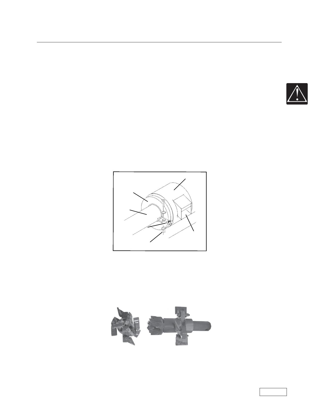
Casing Pusher
Casing Adapter
Casing
Torque Plate
(both sides)
Spoil Ejector
Bolt, Washer, Nut
The casing must always be firmly attached to the boring machine during boring. This is done by welding
“torque plates” to the casing. These “torque plates” are bolted to the master pusher or casing adapter. It pre-
vents the casing from rotating, and in addition, the friction between the casing and the bank soil makes the
boring machine less able to turn over. The casing and torque plates are part of the safety system. Never
operate the rotation without being attached to the casing.
HTD Head
Refer to the Safety Awareness Program in this manual before attempting to operate this machine
Page 27
Safety
Boring Machine Operators Manual
Basic Safety Guidelines
The operator must use care when operating a cutting head with wing cutters. These are designed to
open in front of the casing and make a bore slightly larger than the casing itself. The ideal situation is to
remove the cutting head in the exit pit before removing the auger sections. Otherwise, the auger is rotated
backwards so the wing cutters can retract and the head can be pulled back into the casing. If the operator
tries to operate the auger in the forward rotation with the head inside the casing, the wing cutters can snag
on the inside of the casing.
If the cutting head becomes locked and cannot turn, the operator should move the joystick to neutral and
continue to hold it with the clutch button pushed in, and then push the emergency stop button. Releasing the
clutch can cause damage and injury.
Free-boring (boring without casing) exposes personnel to high-risk hazards of unprotected drill string
and increased possibility of machine upset. All American Augers Boring Machines are designed and sold for
cased bores only. When removing auger from the casing after a bore, keep all personnel away from the
exposed rotating auger.
Refer to the Safety Awareness Program in this manual before attempting to operate this machine
Page 28
Boring Machine Operators Manual
Safety
Safety Alerts
Please note the limited warranty included in this manual. If you have questions on the warranty or
about any part of the machine operation, please contact American Augers.
Safety Alerts
Danger-Rotating Auger and Cutting Head
Rotating auger and cutting head present many shear points where the operator’s limbs could be caught
and injured. They are part of the drill string which is the combination of all rotating components that is
attached to the final drive of the machine. It includes the spoil paddles, auger sections, and the cutting head.
The machine must be turned off whenever work is being done on the auger string, such as installing and pin-
ning auger, removing and unpinning auger, and installing, adjusting, or removing the cutting head. This is
especially important when pinning or unpinning auger sections inside the spoil chamber.
Danger-Rotating Blades
The spoil chamber encloses the rotating blades of the spoil paddles that push the spoil out of the cham-
ber. The close tolerances of the paddles and chamber walls present a hazard. American Augers equips its
Boring Machines with gravity activated spoil doors for a dual purpose. The spoil door shields the exit open-
ing against accidental entry of tools or workers into the spoil chamber, while also protecting nearby person-
nel from flying rock chips. Keep the door closed whenever the machine is operating. Do not stand in front of
the door while the machine is operating. The door is to be opened only with the machine shut down in order
to provide access during the pinning and unpinning of auger sections.
Refer to the Safety Awareness Program in this manual before attempting to operate this machine
Page 29

Safety
Boring Machine Operators Manual
Safety Alerts
Danger-Machine Upset
Boring machines “torque” as a normal reaction of the machine to resistance encountered by the rotating
drill string. When operating in tough conditions, certain combinations of factors can cause a severe, high-
torque machine reaction which can cause a boring machine to upset. These factors include: 1) Operating a
machine at full power in a low gear or reverse; 2) auger or cutting head catching on an obstruction; 3)
advancing into the face rapidly or erratically. It is important to always securely attach the casing to the mas-
ter casing pusher. The weight of the casing and the ground resistance add to the stability of the machine,
deterring machine upset. For spoil removal from the master pusher area, shut off the machine and always
station the worker beside the casing, not the machine. Never allow unnecessary personnel forward of the
operator when the machine is operating.
Caution-Pinch Points
During normal operation of the machine the operator must advance the push bar. The operator must be
aware of the position of the push bar since it moves slowly into position. Always operate the machine from
the platform provided. When using a side-operated machine, the operator must keep personnel away from
the push bar area at the rear of the machine.
Danger-Free Boring
Free-boring exposes personnel to high-risk hazards of unprotected drill string and increased possibility
of machine upset. All American Augers Boring Machines are designed and sold for cased bores only. When
removing auger from the casing after a bore, keep all personnel away from the exposed rotating auger.
Refer to the Safety Awareness Program in this manual before attempting to operate this machine
Page 30

Boring Machine Operators Manual
Safety
Safety Alerts
Warning-”Billboard”
A number of instructions for safe operation are listed on a “billboard” for the operator. Read and under-
stand them before using the machine:
To Avoid Death or Serious Injury
- Read and understand operator’s manual and safety signs (decals) before starting the machine.
- Be sure all personnel know and follow safe operating procedures.
- Engine must be turned off before:
- Opening spoil ejector door
- Working in casing
- Working in exit pit
- Doing any maintenance.
- Properly vent exhaust fumes.
- Always secure auger in casing before lifting.
- Do not modify this machine.
- Always bore with at least a trained operator and a helper.
- Machine may move without warning while in operation.
- Relieve pressure in hydraulic system before servicing.
- Do not operate with guards removed.
- Know and obey all codes and regulations.
Danger-Fire Hazard
Never fuel your machine when the engine is hot or running. Fuel can be ignited by a hot muffler, a spark
or an electrical short and can cause serious injury. Always use an approved container to store fuel.
Refer to the Safety Awareness Program in this manual before attempting to operate this machine
Page 31

Safety
Boring Machine Operators Manual
Safety Alerts
Warning-Keep Hands Clear
Rotating gears present many shear points where an operator's hands and fingers could be caught and
injured. The gears are part of the Quik Tran system that moves the boring machine up and down the track.
The machine must be turned off when servicing the Quik Tran system to prevent accidental rotation of the
gears.
Warning-Pinch Point
When lowering the boring machine into the track, care must be taken to keep hands and feet clear of the
gap between the cam followers on the machine and the top of the track. If a lifting device should fail and the
machine should fall, hands and feet could be crushed between the cam follower and the top of the track.
Refer to the Safety Awareness Program in this manual before attempting to operate this machine
Page 32
Safety
Boring Machine Operators Manual
Safety Alerts
NOTES:
Refer to the Safety Awareness Program in this manual before attempting to operate this machine
Page 33
Safety
Boring Machine Operators Manual
Safety Alerts
Refer to the Safety Awareness Program in this manual before attempting to operate this machine
Page 34

Boring Machine Operators Manual
Safety
Safety Alerts
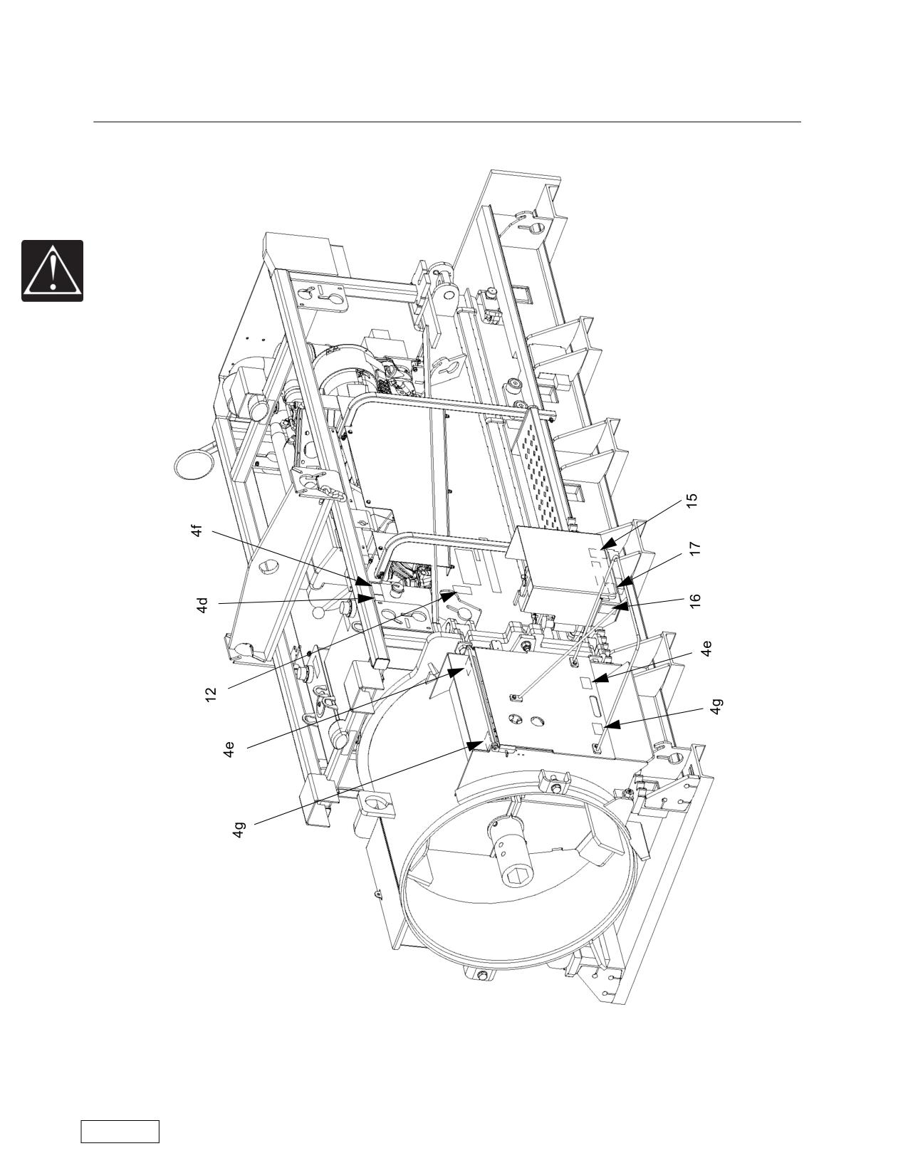
(4d) Precautions against free boring.
(4e) Precautions about rotating blades.
(4f) Precautions about machine upset.
(4g) Precautions about rotating auger.
(12) Precautions about machine rollover.
(15) Precautions about keeping hands clear.
(16) Precautions about pinch points.
(17) Precautions about operating with Quik Tran
motors disengaged.
Refer to the Safety Awareness Program in this manual before attempting to operate this machine
Page 35
Safety
Boring Machine Operators Manual
Safety Alerts
Refer to the Safety Awareness Program in this manual before attempting to operate this machine
Page 36

Boring Machine Operators Manual
Safety
Safety Alerts
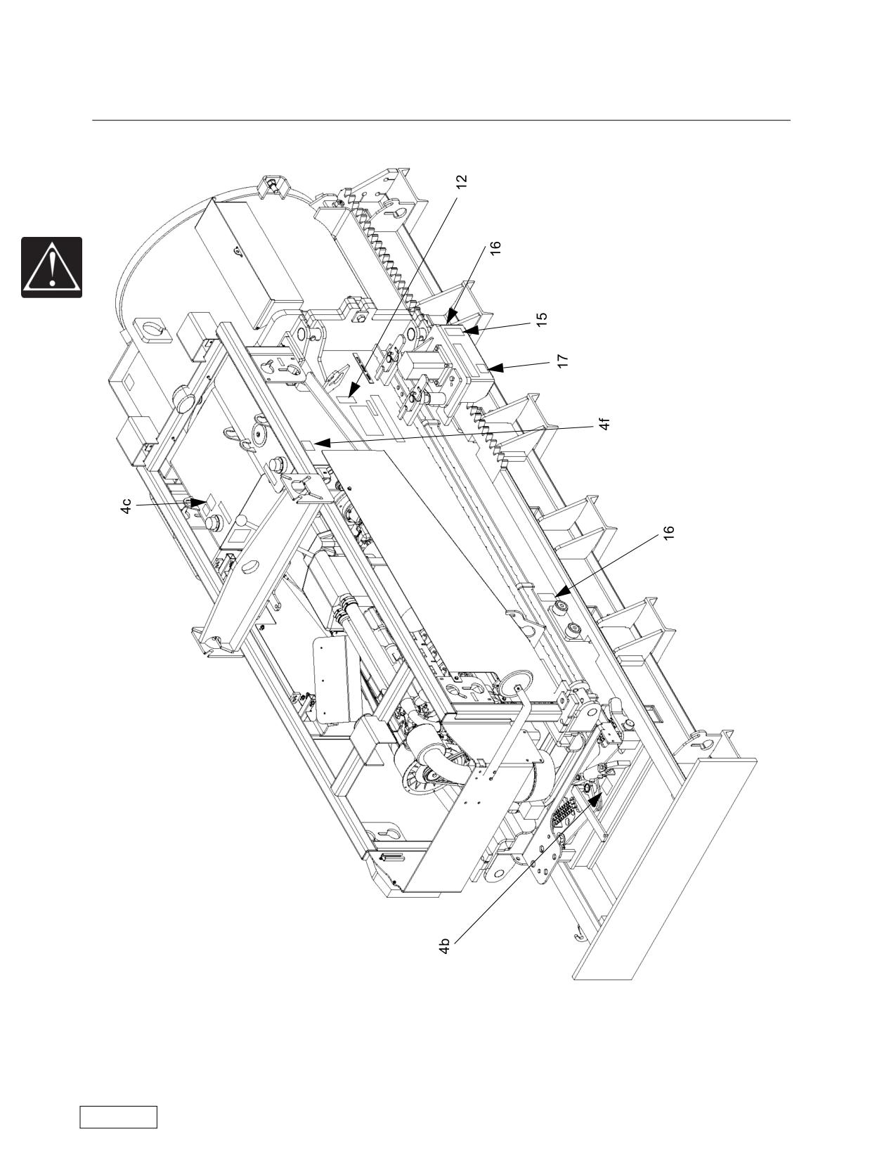
(4b) Precautions about pinch points.
(4c) Precautions about fire hazard.
(4f) Precautions about machine upset.
(12) Precautions about machine rollover.
(15) Precautions about keeeping hands clear.
(16) Precautions about pinch points.
(17) Precautions about operating with Quik Tran
motors disengaged.
Refer to the Safety Awareness Program in this manual before attempting to operate this machine
Page 37
Safety
Boring Machine Operators Manual
Safety Alerts
11
10
4a
6
Refer to the Safety Awareness Program in this manual before attempting to operate this machine
Page 38

Boring Machine Operators Manual
Safety
Safety Alerts
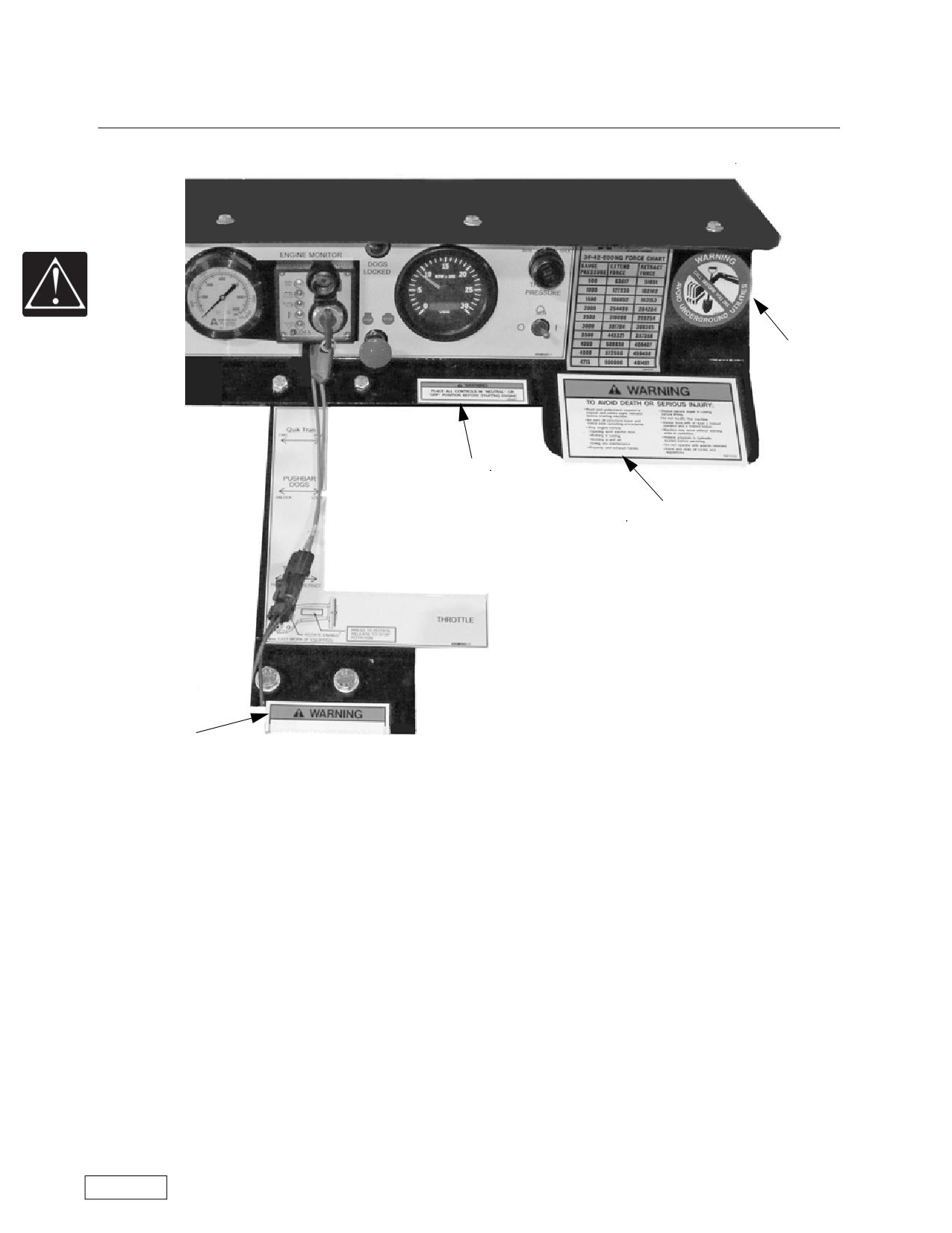
(4a) Precautions death or injury.
(6) Precautions about putting controls in neutral.
(10) Precautions about putting controls in neu-
(11) Precautions about calling before digging.
tral.
NOTE: The placement of the safety decals shown above may vary from model to model as well as the
arrangement of the control area.
Refer to the Safety Awareness Program in this manual before attempting to operate this machine
Page 39
Notes
Boring Machine Operators Manual
Notes
NOTES:
Refer to the Safety Awareness Program in this manual before attempting to operate this machine
Page 40
Boring Machine Operators Manual
Operations
Site Preparation
Operations
Guidelines For Use Of Boring Machines
The following pages outline the basic procedures for making a cased bore. The recommendations and
suggestions offered throughout this manual are based upon years of field experience. They may not be valid
for every job and every situation. The user employs them at his own risk. American Augers encourages you
to contact the factory for technical assistance whenever there is a question about technique or the applica-
tion of a particular machine on the job.
Designing the Job and Preparation of the Entrance Pit
When the job is in the planning stage, provide enough room for safe loading and unloading of equip-
ment, and for spoil removal. Accidents are less likely to occur at sites that are open and kept clear of debris.
In most instances, an entrance pit will be required at the approach side of the bore. The dimensions of
the pit floor, required to install 20 feet (6.1 meter) sections of casing, are found in the Entrance Pit Chart,
Appendix B. These dimensions will provide the most convenient and safest working conditions.
It is the responsibility of the owner to make a safe pit that is in accordance with the rules set forth in the
(OSHA) Code of Federal Regulations 29. There are specific requirements for pit construction, protection,
barricades, traffic control, installation and type of ladders used in the pit and personal safety equipment.
American Augers strongly recommends that the owner become familiar with the requirements of
29CFR1910. Information can be obtained from your Regional Department of Labor Office.
The floor of the pit must be aligned with the proposed casing grade. It must also be solid enough to sup-
port the equipment being used without settling. We recommend the use of a concrete base with base of
crushed stone to aid in removal of water. Contractors sometimes choose to place the track on planking on a
crushed stone base. This technique is effective on short, non-critical bores.
The boring operation requires that a square, secure backstop be provided for the track push plate. The
thrust for the entire bore is transferred through the track to the backstop. Should the backstop fail during the
bore campaign, valuable time will be lost in rebuilding. The backstop should be designed to withstand two
times the maximum thrust of the boring machine being used. American Augers, Inc. strongly recommends
using the services of a competent engineer to assist in the pit base and backstop design.
On all bores, it is recommended that a steel plate be used between the track push plate and the back-
stop. For larger diameter and longer bores, driven sheeting, and/or a poured concrete pad should be con-
sidered. Experience and soil conditions will dictate the best method. A GOOD BASE AND A SECURE
BACKSTOP ARE ESSENTIAL FOR ALL BORES. Refer to the Ground Conditions Chart in Appendix C for
base and backstop recommendations.
The possibility of flooding always exists during the boring operation. The location of a pit sump for
pumping should be considered during the design of the pit. The sump is placed on the right front or right rear,
depending on the slope of the pit floor. This placement will move water away from ejected spoil on the left
side of the machine.
Refer to the Safety Awareness Program in this manual before attempting to operate this machine
Page 41
Operations
Boring Machine Operators Manual
Setting and Aligning the Track
The most critical part of the bore is the setting of the machine track on line and grade. If the alignment is
not right when you start, it is not likely to improve.
NOTICE
The machine and the track sections are designed to be placed seperately.
Always use balanced lift points.
Instructions for the assembly and breakdown of split machines are contained in this manual. Note that
there are two sets of lifting eyes on split machines. The upper set (1), located on the rack, is used to lift the
power package out of the push package. It is NEVER used to lift the entire machine. A second set (2) is
located on the push package and can be used to lift either the entire machine (without track) or the push
package alone.
Lift and place the master track in the pit with the push plate against the backstop. Install the extension
tracks by aligning the tops of the joints and bolting together using Grade 5 bolts in ALL holes. Note that the
track sections are numbered at each end. Extension tracks are installed so that adjoining ends have the
same number. Use a string and plumb bob to align the track sections with the line of the proposed bore,
before setting the machine.
Refer to the Safety Awareness Program in this manual before attempting to operate this machine
Page 42
Boring Machine Operators Manual
Operations
Detailed Controls
Safety Switches and Tethered Deadman Switch
Emergency Stop Push Buttons
This is a red PUSH-to-STOP control, located at the operator’s station. The control must be pulled up/out
(PULL-to-RUN) before the engine will start. The purpose of the control is to provide a rapid means of shut-
ting down the entire machine in the event of an emergency. The location of this control varies from machine
to machine and will be shown when the control station for each machine is discussed.
Tethered Deadman Switch
This is a flexible cord with a clip that attaches to the operator's uniform. If the operator leaves his station,
the cord pulls a switch that stops the engine.
WARNING
Do not attempt to bypass the deadman control. Operation of the machine with the
deadman control disabled can result in injury or death.
Refer to the Safety Awareness Program in this manual before attempting to operate this machine
Page 43
Operations
Boring Machine Operators Manual
Detailed Controls
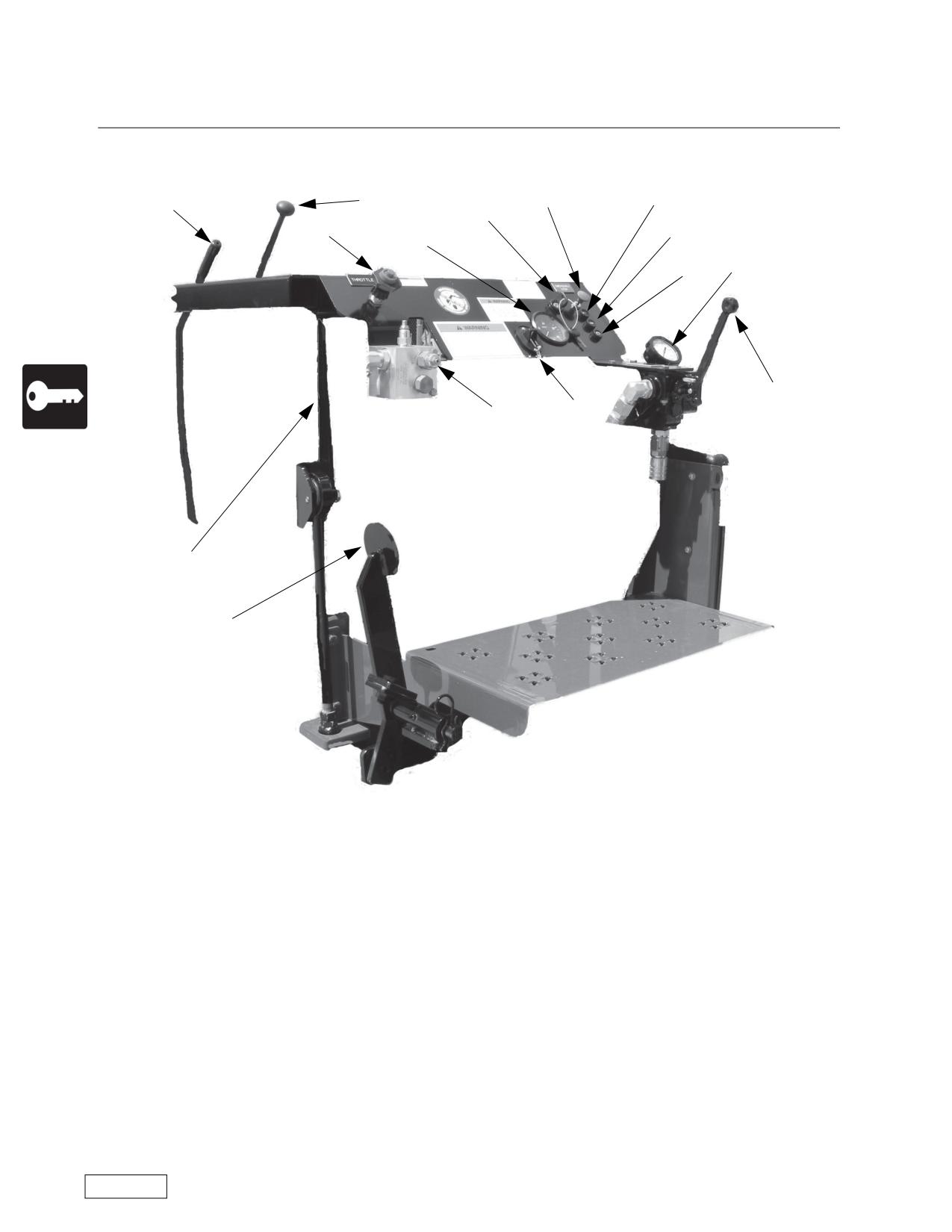
24/30-150 Boring Machine Controls
4
1
9
5
2
8
10
3
11
12
14
25
13
6
7
(1) Emergency Stop -- This is a red PUSH-to-STOP control, located at the operator’s station. The con-
trol must be pulled up/out (PULL-to-RUN) before the engine will start. The purpose of the control is to pro-
vide a rapid means of shutting down the entire machine in the event of an emergency.
(2) Ignition Switch -- Starts the engine.
(3) Tachometer -- A tachometer shows engine speed. Also includes the hour meter display if not a
Caterpillar engine.
(4) Gearshift --The boring machine is equipped with a 4 forward speed gearbox with reverse mechanical
transmission. The shifting pattern is shown on a label in the operator’s view. Operation in forward gears will
cause the auger to rotate FORWARD or clockwise as viewed from the rear of the machine. Reverse gear
will cause the auger to rotate in REVERSE, or counterclockwise as viewed from the rear of the machine.
Drive torque is determined by the gear selected. The highest machine torque is in first and reverse gears.
(5) Clutch -- The clutch is a mechanical automotive type that is disengaged by pulling the clutch lever
toward the operator. The clutch lever must be held by the operator while shifting gears. Releasing the lever
engages the clutch.
(6) Brake Lever
(7) Pushbar Dogs Foot Pedal -- This pedal extends or retracts the pushbar dogs. On the 24/30-150
machines it is spring loaded "out".
Refer to the Safety Awareness Program in this manual before attempting to operate this machine
Page 44
Boring Machine Operators Manual
Operations
Detailed Controls
(8) Throttle -- Pull the throttle to increase the engine speed (RPMs). Most models have a positive throt-
tle, which requires a center button to be depressed before the throttle can be pulled out (accelerate) or
pushed in (decelerate). The throttle position (engine speed) and the gear selected control the auger rotation
speed.
(9) Engine Oil Pressure indicator light.
(10) Engine Oil Temperature indicator light
(11) Alternator operation indicator light.
(12) Thrust Pressure Gauge -- The thrust pressure gauge is matched to the pump system pressure
specified for each machine. Check the pressure rating decal on your machine and be aware of it throughout
your operation. The forward thrust of the machine can be judged in relation to the thrust pressure gauge and
the pressure rating decal. The pressure rating decals for the machines are shown in Appendix A.
(13) Thrust Pressure Adjust -- This control is found on the instrument panel. It allows the operator to limit
the thrust of the boring machine to match its output to job conditions.
(14) Thrust Control -- Push forward on the handle to advace the boring machine and pull back on the
handle to retract the boring machine.
(25) Tethered Deadman Switch -- This is a flexible cord with a clip that attaches to the operator's uni-
form. If the operator leaves his station, the cord pulls a switch that stops the engine.
WARNING
Do not attempt to bypass the deadman control. Operation of the machine with the
deadman control disabled can result in injury or death.
Each boring machine has a fuel gauge on the fuel tank and a sight gauge on the hydraulic tank.
Refer to the Safety Awareness Program in this manual before attempting to operate this machine
Page 45
Operations
Boring Machine Operators Manual
Detailed Controls
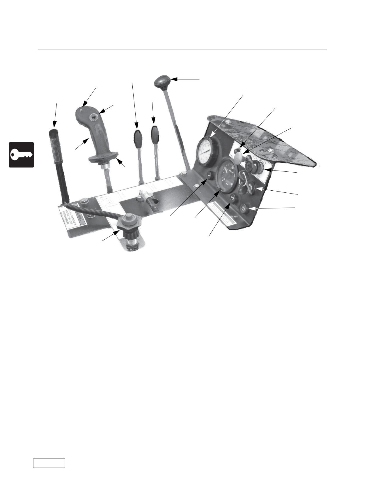
36/42-440NG Boring Machine Controls
4
16
17b
12
5
15
17a
18
1
17c
17
13
2
11
10
3
9
8
(1) Emergency Stop -- This is a red PUSH-to-STOP control, located at the operator’s station. The con-
trol must be pulled up/out (PULL-to-RUN) before the engine will start. The purpose of the control is to pro-
vide a rapid means of shutting down the entire machine in the event of an emergency.
(2) Ignition Switch -- Starts the engine.
(3) Tachometer -- A tachometer shows engine speed. Also includes the hour meter display if not a
Caterpillar engine.
(4) Gearshift --The boring machine is equipped with a 4, 5 or 6 forward speed gearbox with reverse
mechanical transmission. The shifting pattern is shown on a label in the operator’s view. Operation in for-
ward gears will cause the auger to rotate FORWARD or clockwise as viewed from the rear of the machine.
Reverse gear will cause the auger to rotate in REVERSE, or counterclockwise as viewed from the rear of the
machine. Drive torque is determined by the gear selected. The highest machine torque is in first and
reverse gears.
(5) Electric/Hydraulic Clutch-- The clutch is power assisted. The trigger on the joystick engages the
clutch. If the operator releases trigger, the clutch will automatically disengage.
(8) Throttle -- Pull the throttle to increase the engine speed (RPMs). Most models have a positive throt-
tle, which requires a center button to be depressed before the throttle can be pulled out (accelerate) or
pushed in (decelerate). The throttle position (engine speed) and the gear selected control the auger rotation
speed.
(9) Engine Oil Pressure indicator light.
(10) Engine Oil Temperature indicator light
(11) Battery indicator light.
Refer to the Safety Awareness Program in this manual before attempting to operate this machine
Page 46
Boring Machine Operators Manual
Operations
Detailed Controls
(12) Thrust Pressure Gauge -- The thrust pressure gauge is matched to the pump system pressure
specified for each machine. Check the pressure rating decal on your machine and be aware of it throughout
your operation. The forward thrust of the machine can be judged in relation to the thrust pressure gauge and
the pressure rating decal. The pressure rating decals for the machines are shown in Appendix A.
(13) Thrust Pressure Adjust -- This control is found on the instrument panel. It allows the operator to limit
the thrust of the boring machine to match its output to job conditions.
(15) Quik Tran Control -- Some early production models of NG boring machines used a winch and cable
to retract the boring machine to its starting position on the master track. Recent production machines use the
Quik-Tran system to retract to the starting position.
(16) Pushbar Control -- This lever controls a hydraulic circuit that extends or retracts the pushbar dogs.
On the 36/42-440NG boring machine the pushbar dogs are retracted with this valve. The pushbar dogs are
normally spring loaded “out”.
(17) Joystick -- Depending on the model, the joystick contains one or two push buttons and a trigger
switch. Movement of the joystick toward or away from the operator controls the movement of the boring
machine toward or away from the pit face.
(17a) ROTATE ENABLE push button switch, which enables the clutch circuit. Each push button is the
“maintain contact” type. Once the button is pushed, the circuit stays energized even if the engine is stopped.
The operator must push the button a second time to de-energize the circuit.
(17b) ROTATE ENABLE light.
(17c) ROTATE trigger switch that controls the electric clutch. The operator must hold the trigger to keep
the clutch engaged.
(18) Dogs Latched Indicator -- Indicates that the Pushbar Dogs are latched.
Each boring machine has a fuel gauge on the fuel tank and a sight gauge on the hydraulic tank.
Refer to the Safety Awareness Program in this manual before attempting to operate this machine
Page 47
Operations
Boring Machine Operators Manual
Detailed Controls
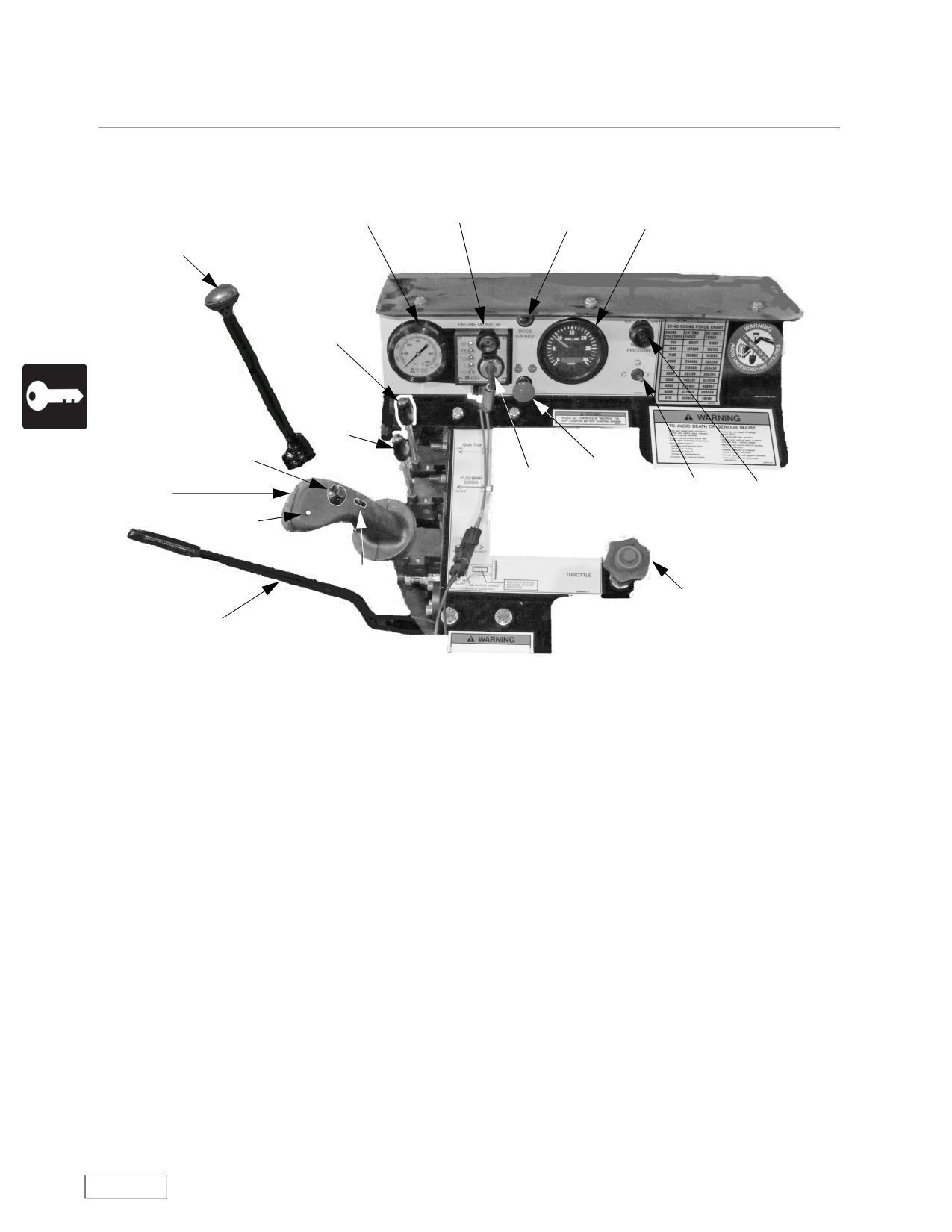
36/42-600NG Boring Machine Controls prior to S/N NG3660002841208
19
12
3
18
4
15
16
17a
1
2
20
13
17
17b
17c
8
5
(1) Emergency Stop -- This is a red PUSH-to-STOP control, located at the operator’s station. The con-
trol must be pulled up/out (PULL-to-RUN) before the engine will start. The purpose of the control is to pro-
vide a rapid means of shutting down the entire machine in the event of an emergency.
(2) Ignition Switch -- Starts the engine.
(3) Tachometer -- A tachometer shows engine speed. Also includes the hour meter display if not a
Caterpillar engine.
(4) Gearshift --The boring machine is equipped with a 4, 5 or 6 forward speed gearbox with reverse
mechanical transmission. The shifting pattern is shown on a label in the operator’s view. Operation in for-
ward gears will cause the auger to rotate FORWARD or clockwise as viewed from the rear of the machine.
Reverse gear will cause the auger to rotate in REVERSE, or counterclockwise as viewed from the rear of the
machine. Drive torque is determined by the gear selected. The highest machine torque is in first and
reverse gears.
(5) Electric/Hydraulic Clutch-- The clutch is power assisted. The trigger on the joystick engages the
clutch. If the operator releases trigger, the clutch will automatically disengage.
(8) Throttle -- Pull the throttle to increase the engine speed (RPMs). Most models have a positive throt-
tle, which requires a center button to be depressed before the throttle can be pulled out (accelerate) or
pushed in (decelerate). The throttle position (engine speed) and the gear selected control the auger rotation
speed.
Refer to the Safety Awareness Program in this manual before attempting to operate this machine
Page 48
Boring Machine Operators Manual
Operations
Detailed Controls
(12) Thrust Pressure Gauge -- The thrust pressure gauge is matched to the pump system pressure
specified for each machine. Check the pressure rating decal on your machine and be aware of it throughout
your operation. The forward thrust of the machine can be judged in relation to the thrust pressure gauge and
the pressure rating decal. The pressure rating decals for the machines are shown in Appendix A.
(13) Thrust Pressure Adjust -- This control is found on the instrument panel. It allows the operator to limit
the thrust of the boring machine to match its output to job conditions.
(15) Quik Tran Control -- Some early production models of NG boring machines used a winch and cable
to retract the boring machine to its starting position on the master track. Recent production machines use the
Quik-Tran system to retract to the starting position.
(16) Pushbar Control -- This lever controls a hydraulic circuit that extends or retracts the pushbar dogs.
On the 36/42-600NG and 42-600NG boring machines the pushbar dogs are retracted with this valve. The
pushbar dogs are normally spring loaded “out”.
(17) Joystick -- Depending on the model, the joystick contains one or two push buttons and a trigger
switch. Movement of the joystick toward or away from the operator controls the movement of the boring
machine toward or away from the pit face.
(17a) ROTATE ENABLE push button switch, which enables the clutch circuit. Each push button is the
“maintain contact” type. Once the button is pushed, the circuit stays energized even if the engine is stopped.
The operator must push the button a second time to de-energize the circuit.
(17b) ROTATE ENABLE light.
(17c) ROTATE trigger switch that controls the electric clutch. The operator must hold the trigger to keep
the clutch engaged.
(18) Dogs Latched Indicator -- Indicates that the Pushbar Dogs are latched.
(19) Engine Monitor -- Lights indicate engine oil pressure, oil temperature and alternator operation. A
tachometer shows engine speed.
(20) Light Switch.
Each boring machine has a fuel gauge on the fuel tank and a sight gauge on the hydraulic tank.
Refer to the Safety Awareness Program in this manual before attempting to operate this machine
Page 49
Operations
Boring Machine Operators Manual
Detailed Controls
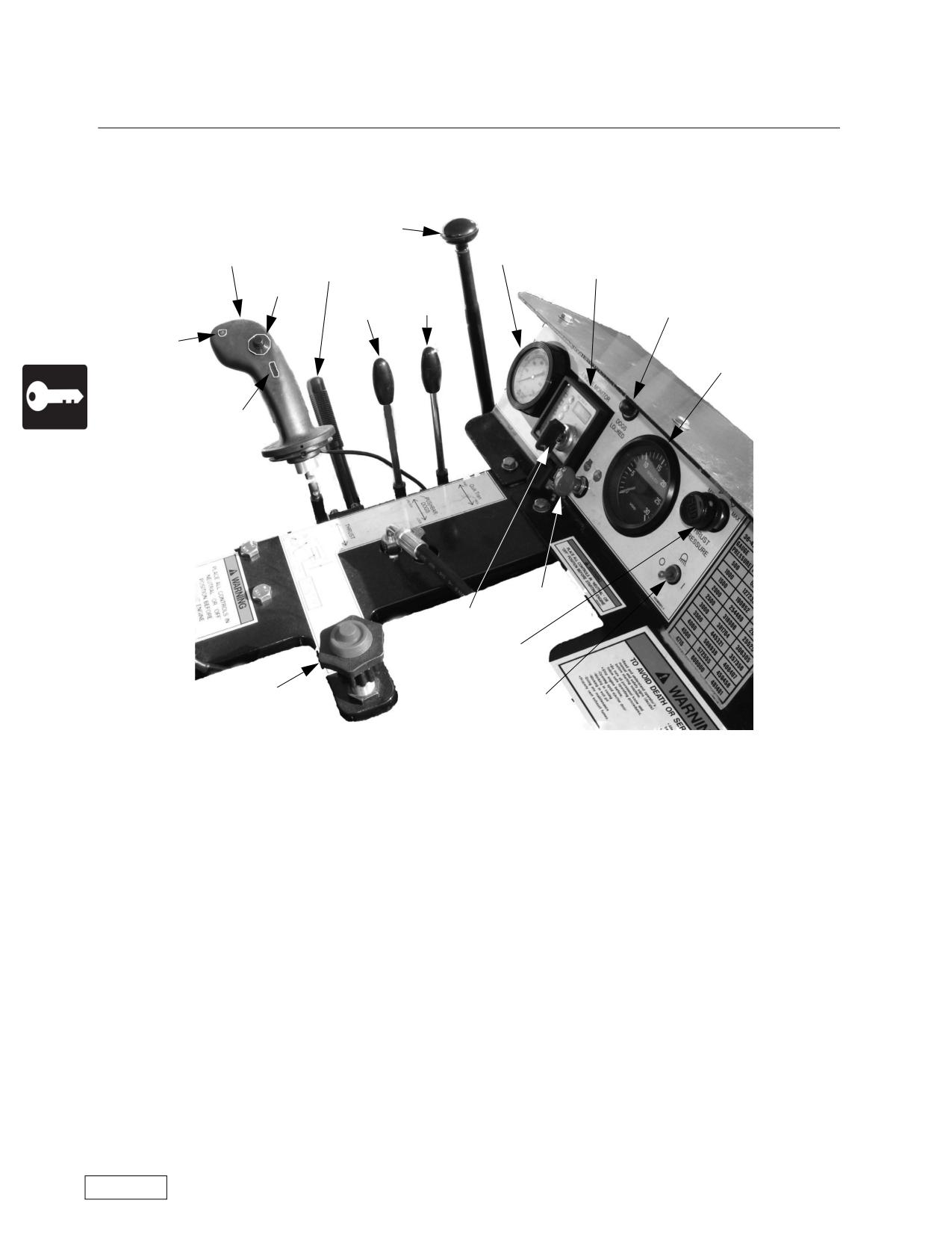
36/42-600NG Boring Machine Controls, S/N NG3660002841208 and
higher
4
17
12
5
19
17a
15
18
16
17b
3
17c
1
2
13
8
20
(1) Emergency Stop -- This is a red PUSH-to-STOP control, located at the operator’s station. The con-
trol must be pulled up/out (PULL-to-RUN) before the engine will start. The purpose of the control is to pro-
vide a rapid means of shutting down the entire machine in the event of an emergency.
(2) Ignition Switch -- Starts the engine and activates the engine pre-heat.
(3) Tachometer -- A tachometer shows engine speed. Also includes the hour meter display if not a
Caterpillar engine.
(4) Gearshift --The boring machine is equipped with a 4, 5 or 6 forward speed gearbox with reverse
mechanical transmission. The shifting pattern is shown on a label in the operator’s view. Operation in for-
ward gears will cause the auger to rotate FORWARD or clockwise as viewed from the rear of the machine.
Reverse gear will cause the auger to rotate in REVERSE, or counterclockwise as viewed from the rear of the
machine. Drive torque is determined by the gear selected. The highest machine torque is in first and
reverse gears.
(5) Electric/Hydraulic Clutch-- The clutch is power assisted. The trigger on the joystick engages the
clutch. If the operator releases trigger, the clutch will automatically disengage.
(8) Throttle -- Pull the throttle to increase the engine speed (RPMs). Most models have a positive throt-
tle, which requires a center button to be depressed before the throttle can be pulled out (accelerate) or
pushed in (decelerate). The throttle position (engine speed) and the gear selected control the auger rotation
speed.
Refer to the Safety Awareness Program in this manual before attempting to operate this machine
Page 50
Boring Machine Operators Manual
Operations
Detailed Controls
(12) Thrust Pressure Gauge -- The thrust pressure gauge is matched to the pump system pressure
specified for each machine. Check the pressure rating decal on your machine and be aware of it throughout
your operation. The forward thrust of the machine can be judged in relation to the thrust pressure gauge and
the pressure rating decal. The pressure rating decals for the machines are shown in Appendix A.
(13) Thrust Pressure Adjust -- This control is found on the instrument panel. It allows the operator to limit
the thrust of the boring machine to match its output to job conditions.
(15) Quik Tran Control -- Some early production models of NG boring machines used a winch and cable
to retract the boring machine to its starting position on the master track. Recent production machines use the
Quik-Tran system to retract to the starting position.
(16) Pushbar Control -- This lever controls a hydraulic circuit that extends or retracts the pushbar dogs.
On the 36/42-600NGboring machines the pushbar dogs are retracted with this valve. The pushbar dogs are
normally spring loaded “out”.
(17) Joystick -- Depending on the model, the joystick contains one or two push buttons and a trigger
switch. Movement of the joystick toward or away from the operator controls the movement of the boring
machine toward or away from the pit face.
(17a) ROTATE ENABLE push button switch, which enables the clutch circuit. Each push button is the
“maintain contact” type. Once the button is pushed, the circuit stays energized even if the engine is stopped.
The operator must push the button a second time to de-energize the circuit.
(17b) ROTATE ENABLE light.
(17c) ROTATE trigger switch that controls the electric clutch. The operator must hold the trigger to keep
the clutch engaged.
(18) Dogs Latched Indicator -- Indicates that the Pushbar Dogs are latched.
(19) Engine Monitor -- Lights indicate engine oil pressure, oil temperature, engine pre-heat and alterna-
tor operation. A tachometer shows engine speed. An hour meter displays the total running hours.
(20) Light Switch.
Each boring machine has a fuel gauge on the fuel tank and a sight gauge on the hydraulic tank.
Refer to the Safety Awareness Program in this manual before attempting to operate this machine
Page 51

Operations
Boring Machine Operators Manual
Detailed Controls
42-600NG Boring Machine Controls
19
12
3
18
4
15
16
17a
1
2
20
13
17
17b
17c
8
5
(1) Emergency Stop -- This is a red PUSH-to-STOP control, located at the operator’s station. The con-
trol must be pulled up/out (PULL-to-RUN) before the engine will start. The purpose of the control is to pro-
vide a rapid means of shutting down the entire machine in the event of an emergency.
(2) Ignition Switch -- Starts the engine.
(3) Tachometer -- A tachometer shows engine speed. Also includes the hour meter display if not a
Caterpillar engine.
(4) Gearshift --The boring machine is equipped with a 4, 5 or 6 forward speed gearbox with reverse
mechanical transmission. The shifting pattern is shown on a label in the operator’s view. Operation in for-
ward gears will cause the auger to rotate FORWARD or clockwise as viewed from the rear of the machine.
Reverse gear will cause the auger to rotate in REVERSE, or counterclockwise as viewed from the rear of the
machine. Drive torque is determined by the gear selected. The highest machine torque is in first and
reverse gears.
(5) Electric/Hydraulic Clutch-- The clutch is power assisted. The trigger on the joystick engages the
clutch. If the operator releases trigger, the clutch will automatically disengage.
(8) Throttle -- Pull the throttle to increase the engine speed (RPMs). Most models have a positive throt-
tle, which requires a center button to be depressed before the throttle can be pulled out (accelerate) or
pushed in (decelerate). The throttle position (engine speed) and the gear selected control the auger rotation
speed.
(12) Thrust Pressure Gauge -- The thrust pressure gauge is matched to the pump system pressure
specified for each machine. Check the pressure rating decal on your machine and be aware of it throughout
your operation. The forward thrust of the machine can be judged in relation to the thrust pressure gauge and
the pressure rating decal. The pressure rating decals for the machines are shown in Appendix A.
Refer to the Safety Awareness Program in this manual before attempting to operate this machine
Page 52
Boring Machine Operators Manual
Operations
Detailed Controls
(13) Thrust Pressure Adjust -- This control is found on the instrument panel. It allows the operator to limit
the thrust of the boring machine to match its output to job conditions.
(15) Quik Tran Control -- Some early production models of NG boring machines used a winch and cable
to retract the boring machine to its starting position on the master track. Recent production machines use the
Quik-Tran system to retract to the starting position.
(16) Pushbar Control -- This lever controls a hydraulic circuit that extends or retracts the pushbar dogs.
On the 42-600NG boring machines the pushbar dogs are retracted with this valve. The pushbar dogs are
normally spring loaded “out”.
(17) Joystick -- Depending on the model, the joystick contains one or two push buttons and a trigger
switch. Movement of the joystick toward or away from the operator controls the movement of the boring
machine toward or away from the pit face.
(17a) ROTATE ENABLE push button switch, which enables the clutch circuit. Each push button is the
“maintain contact” type. Once the button is pushed, the circuit stays energized even if the engine is stopped.
The operator must push the button a second time to de-energize the circuit.
(17b) ROTATE ENABLE light.
(17c) ROTATE trigger switch that controls the electric clutch. The operator must hold the trigger to keep
the clutch engaged.
(18) Dogs Latched Indicator -- Indicates that the Pushbar Dogs are latched.
(19) Engine Monitor -- Lights indicate engine oil pressure, oil temperature and alternator operation. A
tachometer shows engine speed.
(20) Light Switch.
Each boring machine has a fuel gauge on the fuel tank and a sight gauge on the hydraulic tank.
Refer to the Safety Awareness Program in this manual before attempting to operate this machine
Page 53
Operations
Boring Machine Operators Manual
Detailed Controls
48/54-900NG Boring Machine Controls prior to S/N NG48549002281208
18
19
12
4
15
16
5
1
3
20
13
2
17b
17
17e
17a
17c
8
17d
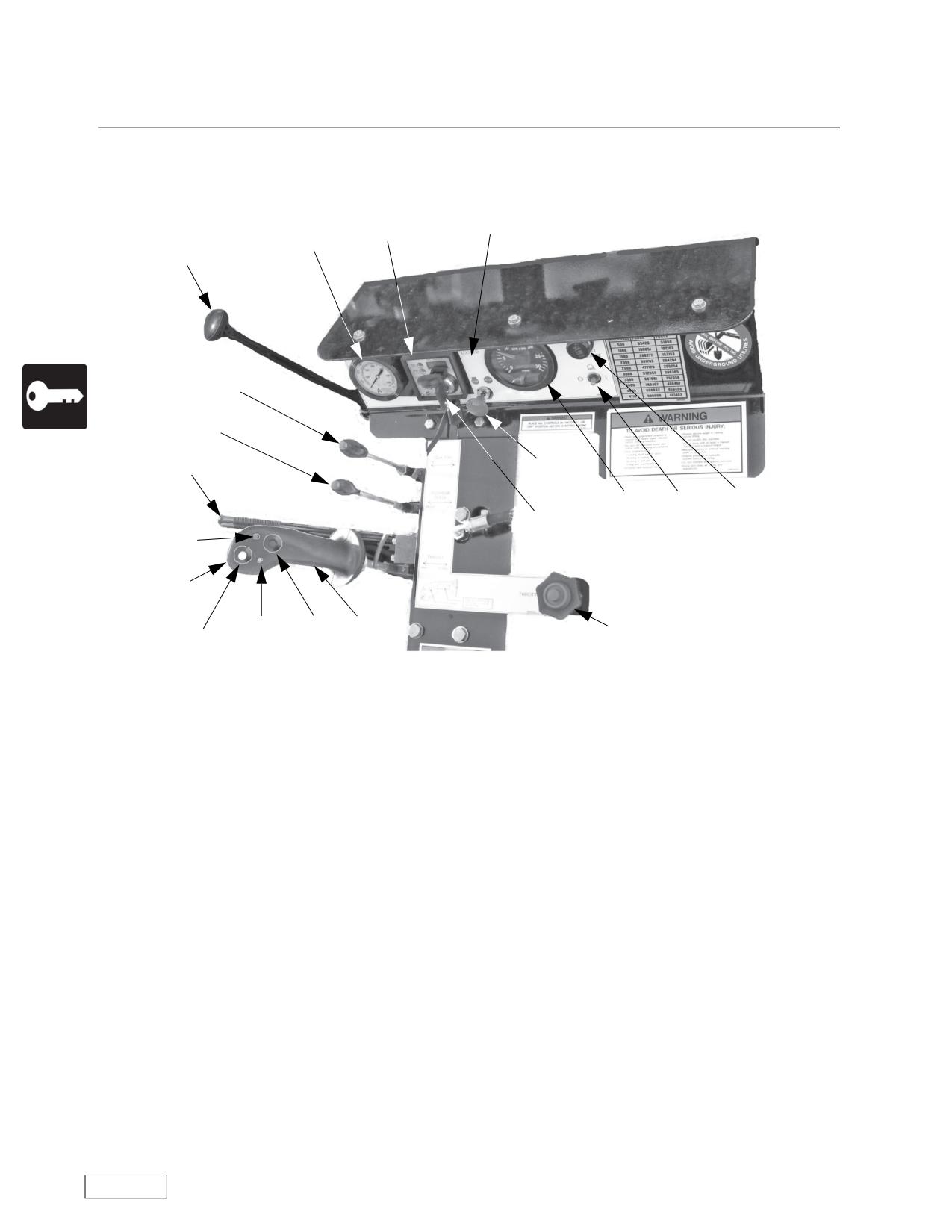
(1) Emergency Stop -- This is a red PUSH-to-STOP control, located at the operator’s station. The con-
trol must be pulled up/out (PULL-to-RUN) before the engine will start. The purpose of the control is to pro-
vide a rapid means of shutting down the entire machine in the event of an emergency.
(2) Ignition Switch -- Starts the engine.
(3) Tachometer -- A tachometer shows engine speed. Also includes the hour meter display if not a
Caterpillar engine.
(4) Gearshift --The boring machine is equipped with a 4, 5 or 6 forward speed gearbox with reverse
mechanical transmission. The shifting pattern is shown on a label in the operator’s view. Operation in for-
ward gears will cause the auger to rotate FORWARD or clockwise as viewed from the rear of the machine.
Reverse gear will cause the auger to rotate in REVERSE, or counterclockwise as viewed from the rear of the
machine. Drive torque is determined by the gear selected. The highest machine torque is in first and
reverse gears.
(5) Electric/Hydraulic Clutch-- The clutch is power assisted. The trigger on the joystick engages the
clutch. If the operator releases trigger, the clutch will automatically disengage.
(8) Throttle -- Pull the throttle to increase the engine speed (RPMs). Most models have a positive throt-
tle, which requires a center button to be depressed before the throttle can be pulled out (accelerate) or
pushed in (decelerate). The throttle position (engine speed) and the gear selected control the auger rotation
speed.
(12) Thrust Pressure Gauge -- The thrust pressure gauge is matched to the pump system pressure
specified for each machine. Check the pressure rating decal on your machine and be aware of it throughout
your operation. The forward thrust of the machine can be judged in relation to the thrust pressure gauge and
the pressure rating decal. The pressure rating decals for the machines are shown in Appendix A.
Refer to the Safety Awareness Program in this manual before attempting to operate this machine
Page 54
Boring Machine Operators Manual
Operations
Detailed Controls
(13) Thrust Pressure Adjust -- This control is found on the instrument panel. It allows the operator to limit
the thrust of the boring machine to match its output to job conditions.
(15) Quik Tran Control -- Some early production models of NG boring machines used a winch and cable
to retract the boring machine to its starting position on the master track. Recent production machines use the
Quik-Tran system to retract to the starting position.
(16) Pushbar Control -- This lever controls a hydraulic circuit that extends or retracts the pushbar dogs.
On the 48/54-900NG boring machines the pushbar dogs are retracted with this valve. The pushbar dogs are
normally spring loaded “out”.
(17) Joystick -- Depending on the model, the joystick contains one or two push buttons and a trigger
switch. Movement of the joystick toward or away from the operator controls the movement of the boring
machine toward or away from the pit face.
(17a) ROTATE ENABLE push button switch, which enables the clutch circuit. Each push button is the
“maintain contact” type. Once the button is pushed, the circuit stays energized even if the engine is stopped.
The operator must push the button a second time to de-energize the circuit.
(17b) ROTATE ENABLE light.
(17c) ROTATE trigger switch that controls the electric clutch. The operator must hold the trigger to keep
the clutch engaged.
(17d) Fast Work Enable pushbutton.
(17e) Fast Work light.
(18) Dogs Latched Indicator -- Indicates that the Pushbar Dogs are latched.
(19) Engine Monitor -- Lights indicate engine oil pressure, oil temperature and alternator operation. A
tachometer shows engine speed.
(20) Light Switch.
Each boring machine has a fuel gauge on the fuel tank and a sight gauge on the hydraulic tank.
Refer to the Safety Awareness Program in this manual before attempting to operate this machine
Page 55
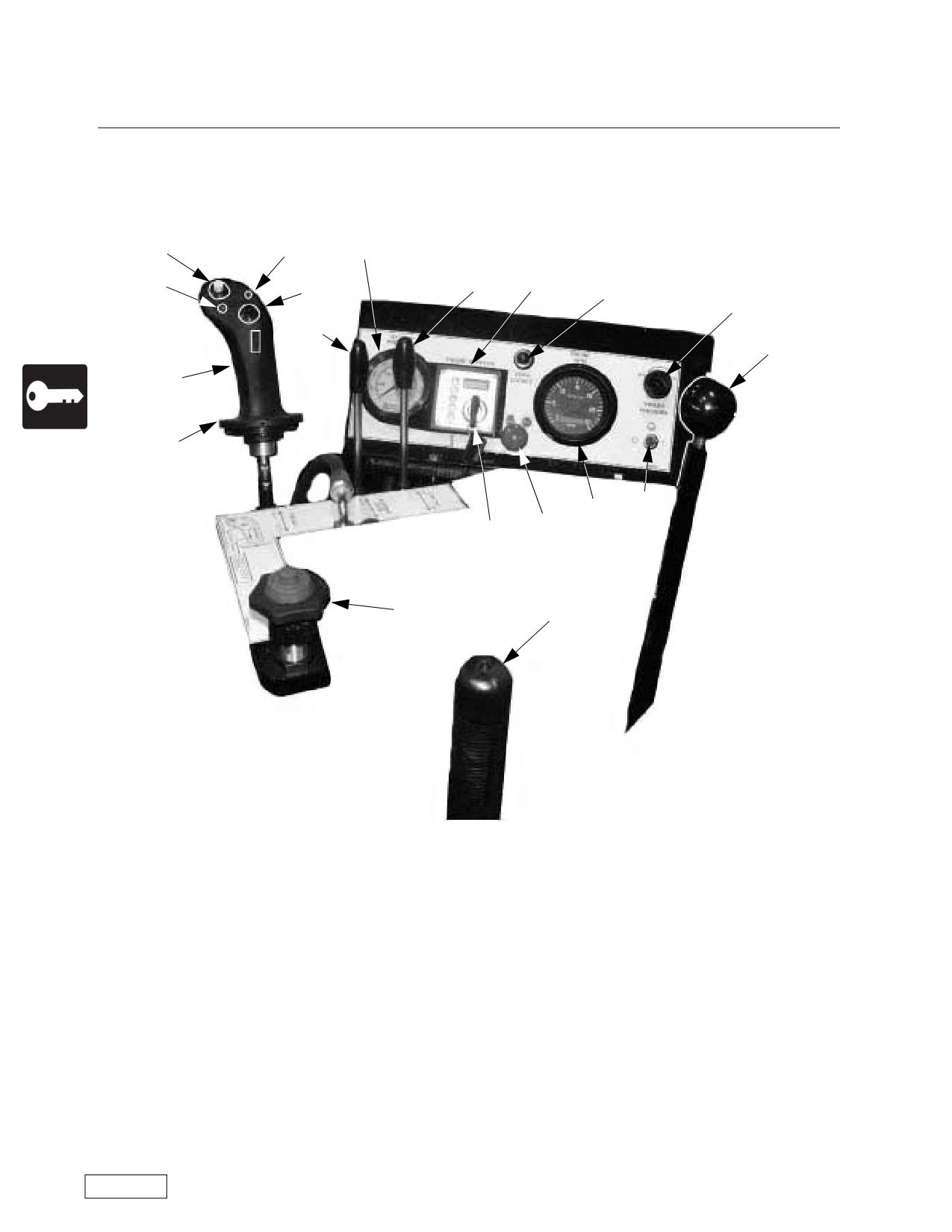
Operations
Boring Machine Operators Manual
Detailed Controls
48/54-900NG Boring Machine Controls S/N NG48549002281208 and
higher
17d
17b
12
17e
15
19
17a
18
13
16
4
17c
17
20
3
1
2
8
5
(1) Emergency Stop -- This is a red PUSH-to-STOP control, located at the operator’s station. The con-
trol must be pulled up/out (PULL-to-RUN) before the engine will start. The purpose of the control is to pro-
vide a rapid means of shutting down the entire machine in the event of an emergency.
(2) Ignition Switch -- Starts the engine and activates the engine pre-heat.
(3) Tachometer -- A tachometer shows engine speed. Also includes the hour meter display if not a
Caterpillar engine.
(4) Gearshift --The boring machine is equipped with a 4, 5 or 6 forward speed gearbox with reverse
mechanical transmission. The shifting pattern is shown on a label in the operator’s view. Operation in for-
ward gears will cause the auger to rotate FORWARD or clockwise as viewed from the rear of the machine.
Reverse gear will cause the auger to rotate in REVERSE, or counterclockwise as viewed from the rear of the
machine. Drive torque is determined by the gear selected. The highest machine torque is in first and
reverse gears.
(5) Electric/Hydraulic Clutch-- The clutch is power assisted. The trigger on the joystick engages the
clutch. If the operator releases trigger, the clutch will automatically disengage.
Refer to the Safety Awareness Program in this manual before attempting to operate this machine
Page 56
Boring Machine Operators Manual
Operations
Detailed Controls
(8) Throttle -- Pull the throttle to increase the engine speed (RPMs). Most models have a positive throt-
tle, which requires a center button to be depressed before the throttle can be pulled out (accelerate) or
pushed in (decelerate). The throttle position (engine speed) and the gear selected control the auger rotation
speed.
(12) Thrust Pressure Gauge -- The thrust pressure gauge is matched to the pump system pressure
specified for each machine. Check the pressure rating decal on your machine and be aware of it throughout
your operation. The forward thrust of the machine can be judged in relation to the thrust pressure gauge and
the pressure rating decal. The pressure rating decals for the machines are shown in Appendix A.
(13) Thrust Pressure Adjust -- This control is found on the instrument panel. It allows the operator to limit
the thrust of the boring machine to match its output to job conditions.
(15) Quik Tran Control -- Some early production models of NG boring machines used a winch and cable
to retract the boring machine to its starting position on the master track. Recent production machines use the
Quik-Tran system to retract to the starting position.
(16) Pushbar Control -- This lever controls a hydraulic circuit that extends or retracts the pushbar dogs.
On the 48/54-900NG boring machines the pushbar dogs are retracted with this valve. The pushbar dogs are
normally spring loaded “out”.
(17) Joystick -- Depending on the model, the joystick contains one or two push buttons and a trigger
switch. Movement of the joystick toward or away from the operator controls the movement of the boring
machine toward or away from the pit face.
(17a) ROTATE ENABLE push button switch, which enables the clutch circuit. Each push button is the
“maintain contact” type. Once the button is pushed, the circuit stays energized even if the engine is stopped.
The operator must push the button a second time to de-energize the circuit.
(17b) ROTATE ENABLE light.
(17c) ROTATE trigger switch that controls the electric clutch. The operator must hold the trigger to keep
the clutch engaged.
(17d) Fast Work Enable pushbutton.
(17e) Fast Work light.
(18) Dogs Latched Indicator -- Indicates that the Pushbar Dogs are latched.
(19) Engine Monitor -- Lights indicate engine oil pressure, oil temperature, engine pre-heat and alterna-
tor operation. A tachometer shows engine speed. An hour meter displays total running hours.
(20) Light Switch.
Each boring machine has a fuel gauge on the fuel tank and a sight gauge on the hydraulic tank.
Refer to the Safety Awareness Program in this manual before attempting to operate this machine
Page 57
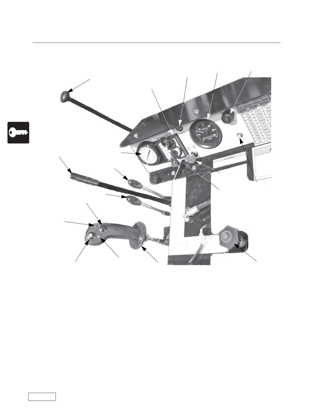
Operations
Boring Machine Operators Manual
Detailed Controls
60-1200NG Boring Machine Controls
13
3
18
4
19
12
5
15
1
20
2
16
17a
17b
17e
8
17d
17
(1) Emergency Stop -- This is a red PUSH-to-STOP control, located at the operator’s station. The con-
trol must be pulled up/out (PULL-to-RUN) before the engine will start. The purpose of the control is to pro-
vide a rapid means of shutting down the entire machine in the event of an emergency.
(2) Ignition Switch -- Starts the engine.
(3) Tachometer -- A tachometer shows engine speed. Also includes the hour meter display if not a
Caterpillar engine.
(4) Gearshift --The boring machine is equipped with a 4, 5 or 6 forward speed gearbox with reverse
mechanical transmission. The shifting pattern is shown on a label in the operator’s view. Operation in for-
ward gears will cause the auger to rotate FORWARD or clockwise as viewed from the rear of the machine.
Reverse gear will cause the auger to rotate in REVERSE, or counterclockwise as viewed from the rear of the
machine. Drive torque is determined by the gear selected. The highest machine torque is in first and
reverse gears.
Refer to the Safety Awareness Program in this manual before attempting to operate this machine
Page 58
Boring Machine Operators Manual
Operations
Detailed Controls
(5) Electric/Hydraulic Clutch-- The clutch is power assisted. The trigger on the joystick engages the
clutch. If the operator releases trigger, the clutch will automatically disengage.
(8) Throttle -- Pull the throttle to increase the engine speed (RPMs). Most models have a positive throt-
tle, which requires a center button to be depressed before the throttle can be pulled out (accelerate) or
pushed in (decelerate). The throttle position (engine speed) and the gear selected control the auger rotation
speed.
(12) Thrust Pressure Gauge -- The thrust pressure gauge is matched to the pump system pressure
specified for each machine. Check the pressure rating decal on your machine and be aware of it throughout
your operation. The forward thrust of the machine can be judged in relation to the thrust pressure gauge and
the pressure rating decal. The pressure rating decals for the machines are shown in Appendix A.
(13) Thrust Pressure Adjust -- This control is found on the instrument panel. It allows the operator to limit
the thrust of the boring machine to match its output to job conditions.
(15) Quik Tran Control -- Some early production models of NG boring machines used a winch and cable
to retract the boring machine to its starting position on the master track. Recent production machines use the
Quik-Tran system to retract to the starting position.
(16) Pushbar Control -- This lever controls a hydraulic circuit that extends or retracts the pushbar dogs.
On the 60 inch machine the pushbar is extended with this valve.
(17) Joystick -- Depending on the model, the joystick contains one or two push buttons and a trigger
switch. Movement of the joystick toward or away from the operator controls the movement of the boring
machine toward or away from the pit face.
(17a) ROTATE ENABLE push button switch, which enables the clutch circuit. Each push button is the
“maintain contact” type. Once the button is pushed, the circuit stays energized even if the engine is stopped.
The operator must push the button a second time to de-energize the circuit.
(17b) ROTATE ENABLE light.
(17d) Fast Work Enable pushbutton.
(17e) Fast Work light.
(18) Dogs Latched Indicator -- Indicates that the Pushbar Dogs are latched.
(19) Engine Monitor -- Lights indicate engine oil pressure, oil temperature and alternator operation. A
tachometer shows engine speed.
(20) Light Switch.
Each boring machine has a fuel gauge on the fuel tank and a sight gauge on the hydraulic tank.
Refer to the Safety Awareness Program in this manual before attempting to operate this machine
Page 59
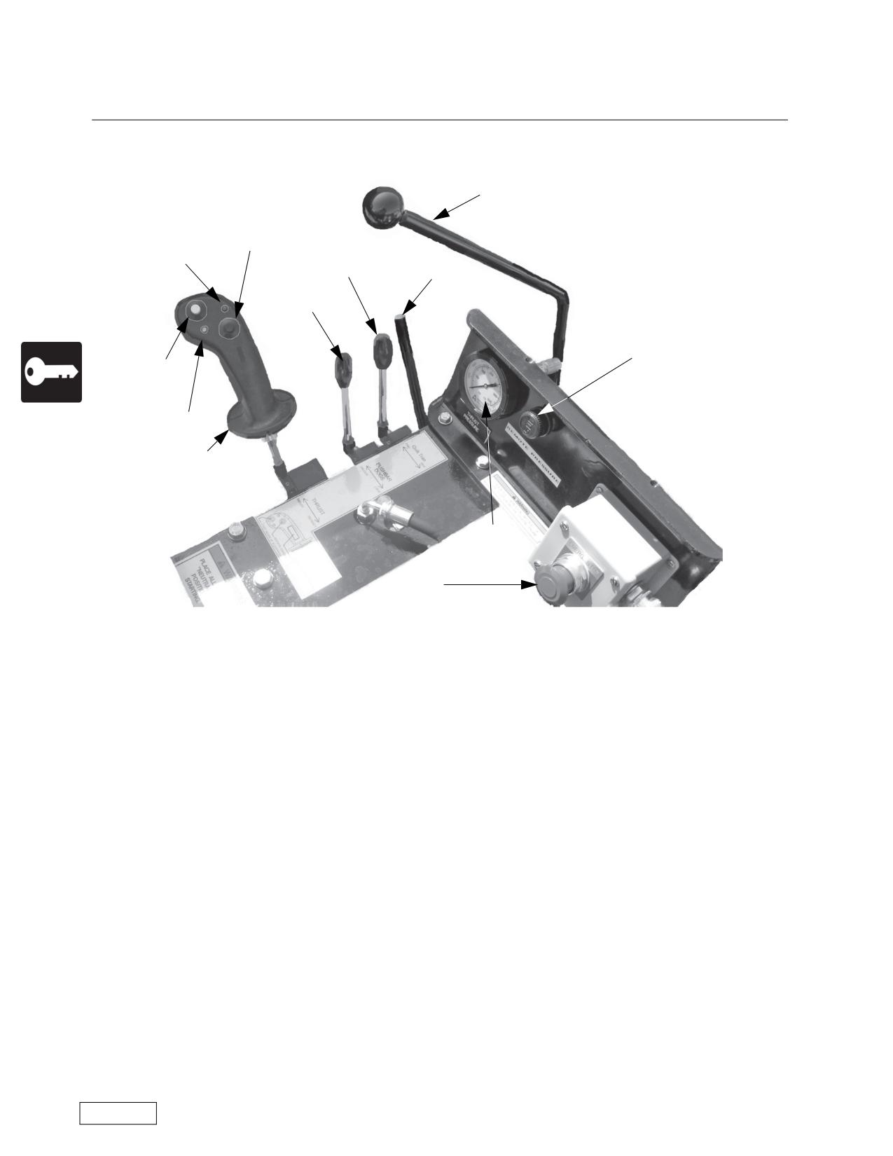
Operations
Boring Machine Operators Manual
Detailed Controls
72-1200NG Boring Machine Controls
4
17a
17b
15
5
16
13
17d
17e
17
12
1
Refer to the Safety Awareness Program in this manual before attempting to operate this machine
Page 60
Boring Machine Operators Manual
Operations
Detailed Controls
72-1200NG Boring Machine Controls
(1) Emergency Stop -- This is a red PUSH-to-STOP control, located at the operator’s station. The con-
trol must be pulled up/out (PULL-to-RUN) before the engine will start. The purpose of the control is to pro-
vide a rapid means of shutting down the entire machine in the event of an emergency.
(4) Gearshift --The boring machine is equipped with a 4, 5 or 6 forward speed gearbox with reverse
mechanical transmission. The shifting pattern is shown on a label in the operator’s view. Operation in for-
ward gears will cause the auger to rotate FORWARD or clockwise as viewed from the rear of the machine.
Reverse gear will cause the auger to rotate in REVERSE, or counterclockwise as viewed from the rear of the
machine. Drive torque is determined by the gear selected. The highest machine torque is in first and
reverse gears.
(5) Electric/Hydraulic Clutch-- The clutch is power assisted. The trigger on the joystick engages the
clutch. If the operator releases trigger, the clutch will automatically disengage.
(12) Thrust Pressure Gauge -- The thrust pressure gauge is matched to the pump system pressure
specified for each machine. Check the pressure rating decal on your machine and be aware of it throughout
your operation. The forward thrust of the machine can be judged in relation to the thrust pressure gauge and
the pressure rating decal. The pressure rating decals for the machines are shown in Appendix A.
(13) Thrust Pressure Adjust -- This control is found on the instrument panel. It allows the operator to limit
the thrust of the boring machine to match its output to job conditions.
(15) Quik Tran Control -- Some early production models of NG boring machines used a winch and cable
to retract the boring machine to its starting position on the master track. Recent production machines use the
Quik-Tran system to retract to the starting position.
(16) Pushbar Control -- This lever controls a hydraulic circuit that extends or retracts the pushbar dogs.
On the 72 inch machine the pushbar is extended with this valve.
(17) Joystick -- Depending on the model, the joystick contains one or two push buttons and a trigger
switch. Movement of the joystick toward or away from the operator controls the movement of the boring
machine toward or away from the pit face.
(17a) ROTATE ENABLE push button switch, which enables the clutch circuit. Each push button is the
“maintain contact” type. Once the button is pushed, the circuit stays energized even if the engine is stopped.
The operator must push the button a second time to de-energize the circuit.
(17b) ROTATE ENABLE light.
(17d) Fast Work Enable pushbutton.
(17e) Fast Work light.(18) Dogs Latched Indicator -- Indicates that the Pushbar Dogs are latched.
Refer to the Safety Awareness Program in this manual before attempting to operate this machine
Page 61
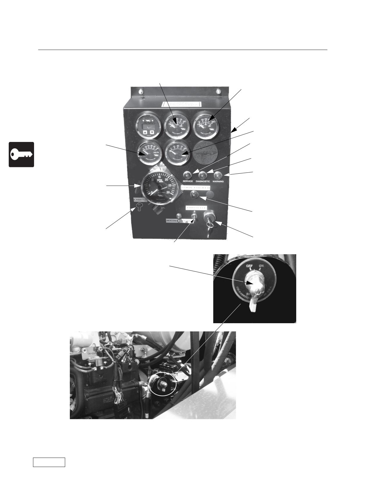
Operations
Boring Machine Operators Manual
Detailed Controls
72-1200NG Boring Machine Controls
10
9
19
24
21
11
23
22
3
18
20
2
8
25
Refer to the Safety Awareness Program in this manual before attempting to operate this machine
Page 62
Boring Machine Operators Manual
Operations
Detailed Controls
72-1200NG Boring Machine Controls
(2) Ignition Switch -- Starts the engine.
(3) Tachometer -- A tachometer shows engine speed. Also includes the hour meter display if not a
Caterpillar engine.
(8) Throttle -- Push the throttle up increase the engine speed (RPMs) and push the throttle down to
decrease engine speed. The throttle position (engine speed) and the gear selected control the auger rotation
speed.
(9) Oil temperature gauge.
(10) Oil pressure gauge.
(11) Alternator Voltage.
(19) Murphy System-- If the engine coolant gets too hot, or if the engine oil pressure gets too low, the
Murphy System will stop the engine. The engine also has an electronic system that indicates when mainte-
nance is due. Ths interval is indicated by the red light on the control panel.
(20) Light Switch.
(21) Service Light.
(22) Warning Light.
(23) Diagnostic Light.
(24) Percent engine loading gauge.
(25) Battery disconnect switch. Turn left to disconnect the batteries and turn right to connect the batter-
ies. Do not use the Battery disconnect switch to turn off the boring machine. Use of the switch in this manner
could result in damage to the boring machine.
Each boring machine has a fuel gauge on the fuel tank and a sight gauge on the hydraulic tank.
Refer to the Safety Awareness Program in this manual before attempting to operate this machine
Page 63
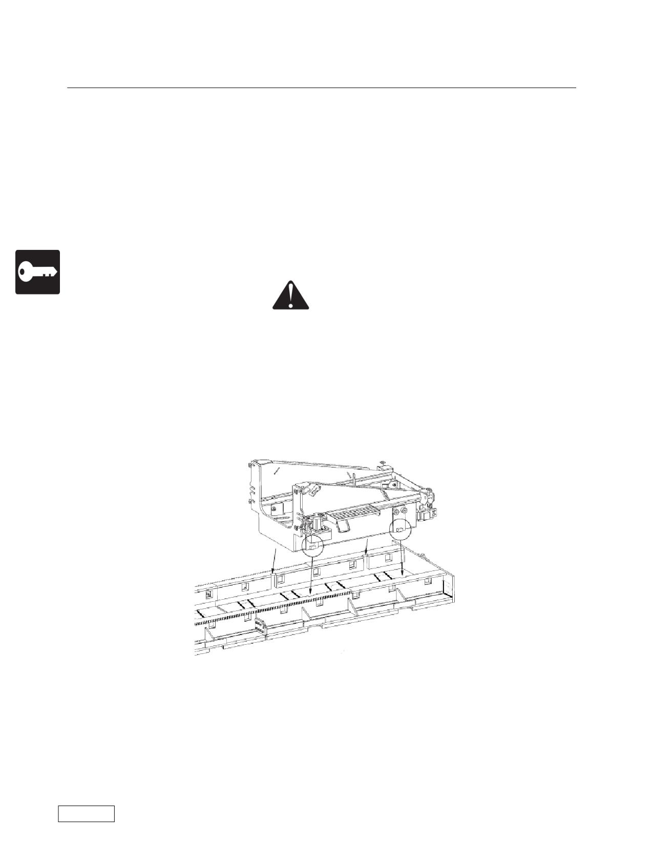
Operations
Boring Machine Operators Manual
Installing the Boring Machine
Set the machine on the master track and engage the push bar dogs in the rear most holes in the track.
Install the slide rails or on earlier machines (Pre NG) clamp hook rollers then lower and secure the master
casing pusher. Install casing adapters, master saddle, and saddle adapters as required to fit the bore cas-
ing. Before the first joint of casing and auger is installed, the fluid levels should be checked and the machine
started and tested operationally.
Assembly of Split-Design Machines
Split-design feature: Refer to the drawing on Page 17. Two sets of lift points are provided on split
machines. The upper set, located on the rack, is used to lift the power package out of the base push unit. It is
NEVER used to lift the entire machine. A second set of lift points is located on the base push unit. It can be
used to lift either the base unit alone or the entire machine. With either operation we recommend the use of a
spreader bar as shown.
CAUTION
Never use the upper lift points to lift the entire machine.
To assemble a split machine:
Attach the spreader bar chains so that the base is level.
When inserting base into master track, Quik Tran mechanism must be in the open position to ensure no
damage is done to the motor/pinion.
Align keys on the base with notches in the Master Track. Stay clear of shear and pinch points while guid-
ing the base unit during assembly. Center the base assembly between the tracks. Measure from the corners
of the base assembly to the inside of the gear rack. The distance should be equal at all four corners.
Once base is in place, swing Quik Tran mechanism into the closed position as shown in the following fig-
ures and install the last lock pin.
Refer to the Safety Awareness Program in this manual before attempting to operate this machine
Page 64
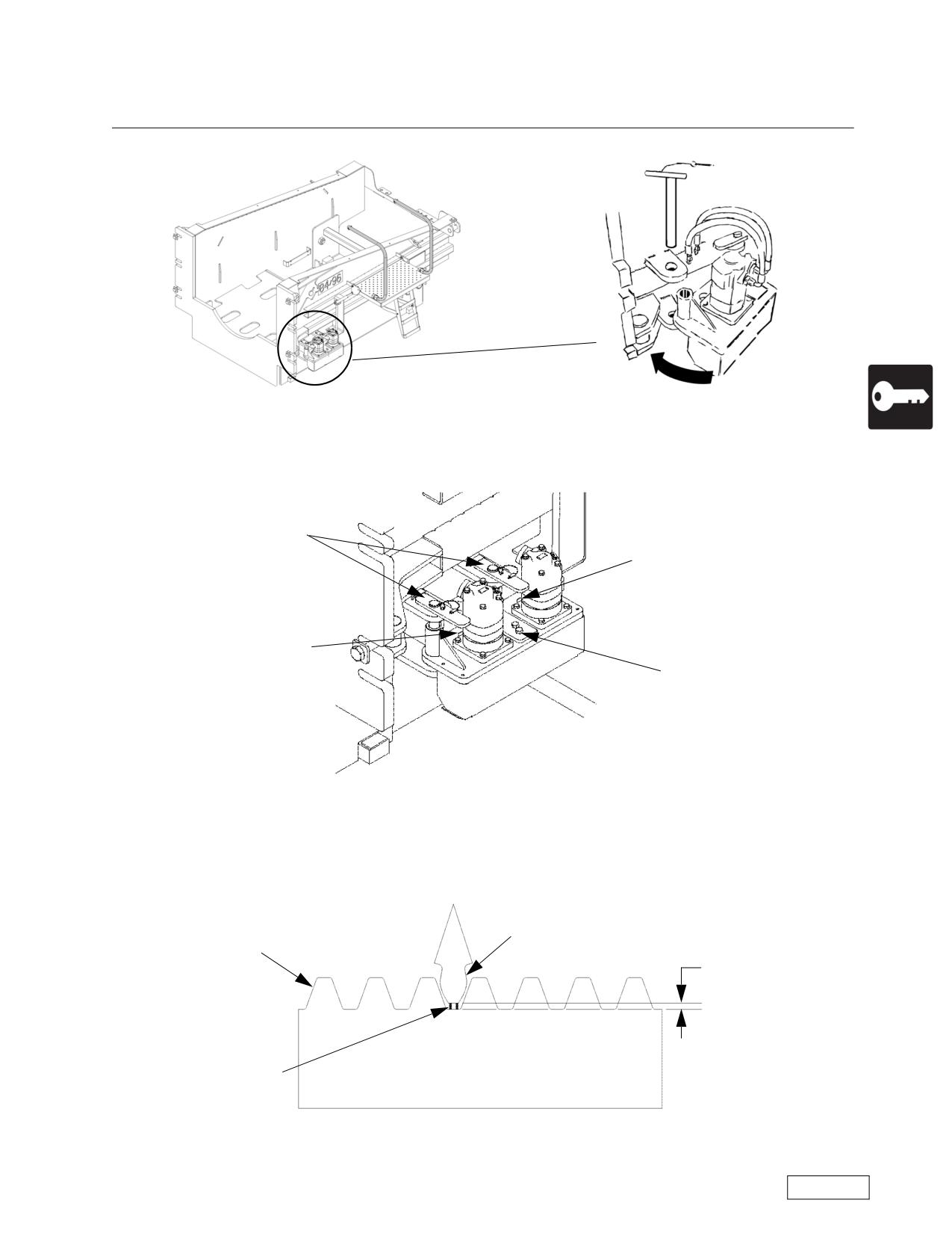
Boring Machine Operators Manual
Operations
Installing the Boring Machine
Loosen the 5/8 bolts. On Auger Boring Machines with a single Quik Tran motor there is one bolt and on
Auger Boring Machines with dual Quik Tran motors there are two bolts.
Lock Pins
Location Hole
Location Hole
5/8 Bolts
Place a 1 piece of 1/4 inch key stock through the location hole and between the root of the teeth on the
rack and the tip of the teeth on the pinion drive for single motor. Use 2 pieces of 1/4 inch key stock for dual
motors, 1piece at each gear/rack combination. See illustration below.
Gear Rack
Gear Tooth on Pinion
on Track
1/4 Inch
1/4 Inch Keystock
Refer to the Safety Awareness Program in this manual before attempting to operate this machine
Page 65
Operations
Boring Machine Operators Manual
Installing the Boring Machine
Push in on the Quik Tran Assembly, while the key stock is in position, and torque the 5/8 bolts to 100 Ft-
pounds for single motor Boring Machine and 125 Ft-pounds for dual motor
For Boring Machines with dual motors the process will have to be performed for each motor.
Repeat the adjustment on the opposite side of the base and track assembly
If mechanism will not engage properly the pinion is most likely not in time with the master track. To prop-
erly install the Quik Tran units the power package has to be installed.
Attach the spreader bar chains so that the power package is level.
Carefully lower and install the power package into the base unit. Stay clear of shear and pinch points
while guiding the power package during assembly.
The power package will align itself as it is lowered into the base unit.
After the power package is seated, remove the spreader bar.
Clamp swivel bolts which hold master pusher to base unit.
Couple the hydraulic hoses and make electrical connections.
Latch and tighten all four corner swivel bolts.
Before Operating The Engine
A factory instruction manual for each specific engine is supplied with the boring machine. Operation and
maintenance information is included in the engine manual. The following instructions cover only the starting
and stopping procedures. All other engine maintenance and repair instructions are contained in the engine
manufacturer’s factory manual.
Before Starting
1. Check engine oil level. Fill as needed with the oil required for your engine.
2. Check fuel level. Diesel engines use #2 diesel fuel with a minimum Cetane rating of 50. Never let the
diesel fuel tank run dry! If the tank is dry, bleed the fuel system as outlined in the engine manual.
3. Check air filter indicator.
Starting Engine:
1. Make sure spoil chamber door is closed and the transmission is in neutral.
2. Pull emergency stop switch UP.
3. Set throttle at 1/2 speed position.
4. Turn ignition key switch to run position. Indicator lights will come on.
5. Reduce throttle setting to allow engine to warm up for one minute.
Start machine and engage pushbar with track.
Keep all people away from both Quik Tran motors.
Slowly activate Quik Tran function on control station to rotate motors into a position that will allow them
to engage the track.
• Once motor is engaged into the track insert retaining pin and rotate to line up lanyard pin holes.
• Insert lanyard pin as shown in the following figure. The retaining pin is now locked in.
Refer to the Safety Awareness Program in this manual before attempting to operate this machine
Page 66
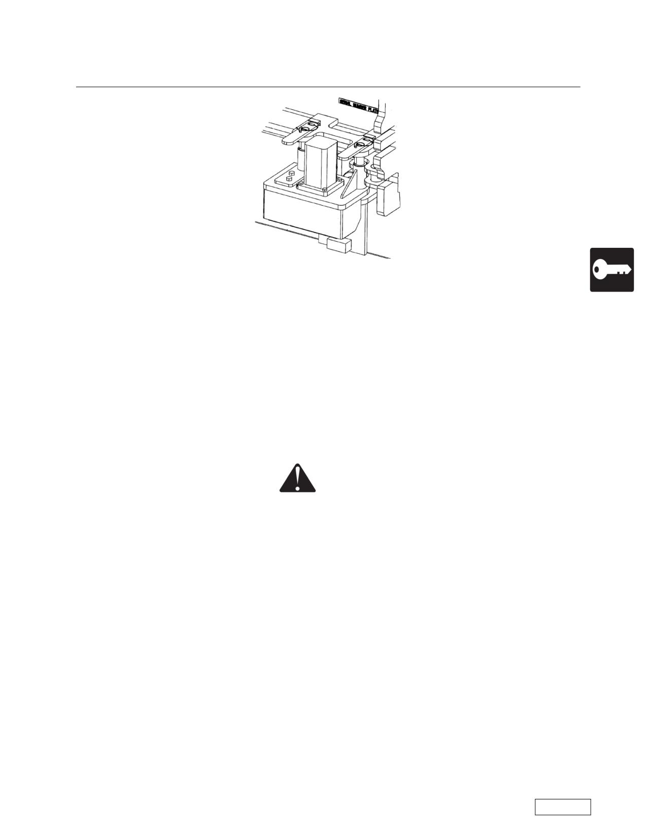
Boring Machine Operators Manual
Operations
Installing the Boring Machine
• Repeat procedure for opposite side.
• Once both sides have been engaged start machine, disengage pushbar and run machine up and down
track to ensure Quik Tran is operating normally.
Stopping Engine
1. When an engine has been operating under load, the engine should be allowed to idle to cool down
before shutting it off.
2. Push emergency stop switch in. Turn ignition key switch to off position. Remove key for security.
The machine is ready for use.
Quik Tran
CAUTION
Under no circumstance remove or loosen any bolts on the mechanism, doing so will
cause loss of backlash in gearing and cause damage to the mechanism.
Quik Tran operation
• Quik Tran function is not designed to be used in conjunction with rotating cutting head/auger.
• Before operating Quik Tran ensure that all quick disconnects and electrical connections are fully
engaged and functioning properly.
• The control lever that operates the Quik Tran function is located furthest away from the thrust lever, the
pushbar lever is located between the two functions.
• Before operating the Quik Tran function you must disengage the pushbar from the track.
• Activating the Quik Tran lever towards the master pusher will cause the machine to move forward
(thrust). Activating the lever towards the pushbar will cause the machine to travel backward (retract).
Refer to the Safety Awareness Program in this manual before attempting to operate this machine
Page 67
Operations
Boring Machine Operators Manual
Preparation of Casing
Improperly prepared or poor quality casing can make the job more difficult and introduce hazards that
are unnecessary. Casing normally has a machine cut bevel on one end and is cut square on the other. Exact
20 foot (6.1 m) lengths will keep the head at the correct location relative to the casing. Smooth walls will
reduce the push required and the tendency of the casing to rotate during the bore. Casing is normally coated
with a bituminous coating on the outside only.
Preparation of the lead section of casing is best accomplished in the yard. Refer to the Cutting Heads,
Appendix D, and Ground Conditions Chart, Appendix C, for selection of a cutting head. American Augers
recommends that our steering head be used on long and/or critical bores.
Loading auger into casing is best done in the yard, then transported to the jobsite ready to use. The lead
section of casing is cut to determine the head position listed in the Ground Conditions Chart. This section is
loaded with the head flush or inside the casing so the male hex shank is exposed for the ease of coupling to
the machine chuck. The follow-up casings are loaded male end first so that the female hex socket is
exposed for ease of coupling the auger joint at the job site.
When the sections of casing and auger are loaded on the truck, stack the auger with the exposed flight
at the same end to simplify the unloading at the job site.
Banding the Casing
The use of a partial band at the head end of the casing is recommended when boring in most soil condi-
tions. The band compacts the soil and relieves pressure on the casing. Placement of the band is a matter of
personal experience, but it is usually 3/8 x 6 inch (1 x 15 cm), rolled to fit the casing. A gap of approximately
10 inches (25.4 cm) is left at the bottom. Place the band so that it leads the casing by about 1/2 inch (1.2
cm). Weld securely front inside and rear outside. The inside chamfer of the front weld will provide a lifting
action for the casing if the thrust is rapid. If wing cutters are used to overcut the casing, a falling action will
occur.
The above method is typical for most applications. However, other approaches to banding the casing
can be used and are determined by the application, soil conditions and user experience.
Refer to the Safety Awareness Program in this manual before attempting to operate this machine
Page 68
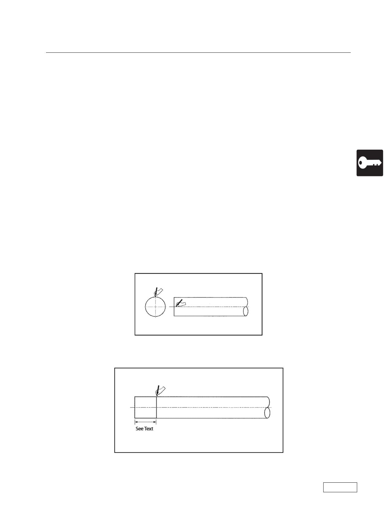
Boring Machine Operators Manual
Operations
Constructing the Steering Head
Materials
Materials listed below are for building a steering head using first 20 foot (6.1 m) piece of casing of bore.
It is advisable when the cutting head is pulled inside of the casing to build a 4 foot (1.22 m) Steering head out
of material at least 0.750 inch (1.95 cm) wall thickness casing. When using a 4 foot (1.22 m) Steering head,
remember to cut first piece of casing off to allow for steering head length.
o
1 piece casing, cut to length for 1-1/2 inch (3.8 cm) clearance from back of wing cutters to casing
band.
• For bores of 24 inch (61 cm) and larger, casing should be 20 foot 3-1/2 inch (6.19 m) in length.
• For bores smaller than 24 inch (61 cm), casing should be 19 foot 10-1/2 inch (6.07 m) in length
o American Augers steering head kit
o Sensing head
o Steering pipe (3/4 inch (1.9 cm) schedule 80 PE pipe). Schedule 80 pipe to be cut to 19 foot 8 inch
(6.1 m) before welding on the steering pipe ends. The first steering pipe should be between 16 and 17 foot
(4.9 and 5.2 m) length for the steering head.
o
1 pc 1-1/2 inch (3.8 cm) schedule 40 T & C pipe. (Covers steering pipe and carries bentonite)
o
2 pcs 1/2 inch (1.29 cm) schedule 40 T & C pipe (Dutch level line and gravity feed waterline)
o
1 pc 1-1/2 inch (3.8 cm) pipe nipple 8 inch (20.3 cm) long
o
1 pc 1-1/2 inch (3.8 cm) to 3/4 inch (1.9 cm) pipe tee
o
1 pc 1-1/2 inch (3.8 cm) pipe cap
o
3/8 x 6 inch (.95 x 15.2 cm) ring (can be cut off of same size casing as bore)
Layout Instructions
Step 1. Locate center lines on casing (one way to divide casing into 4 sections is to multiply diameter by
3.1416 then divide by 4.)
Step 1
Step 2. Mark a line around casing a distance equal to the diameter of the casing. For 12 inch (30.5 cm)
casing, mark at 12inch (30.5 cm). For 24 inch (61 cm) casing, mark at 24 inch (61 cm) and so on.
Step 2
Refer to the Safety Awareness Program in this manual before attempting to operate this machine
Page 69
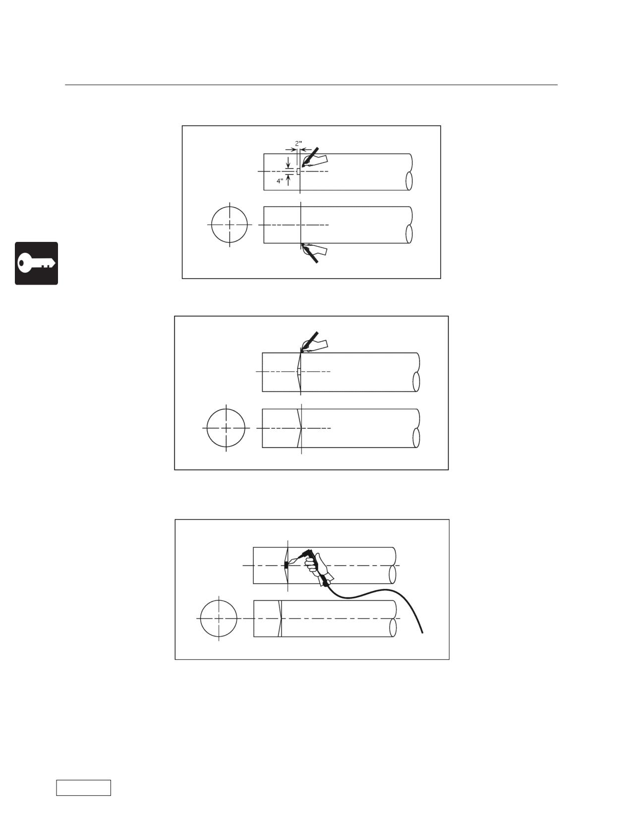
Operations
Boring Machine Operators Manual
Constructing the Steering Head
Step 3. Mark a 2 inch (5.1 cm) x 4 inch (10.2 cm) rectangle on center at top and bottom of the casing
along the line you marked in Step 2
Step 3
Step 4. Mark a line from the corner of to rectangle to the side on top and bottom of casing as shown.
Step 4
Step 5. Using the scribed lines as a guide, cut the casing from the rectangle to the side center point on
both the top and bottom of the casing. Roll the casing and repeat the process on the opposite side.
Step 5
Refer to the Safety Awareness Program in this manual before attempting to operate this machine
Page 70
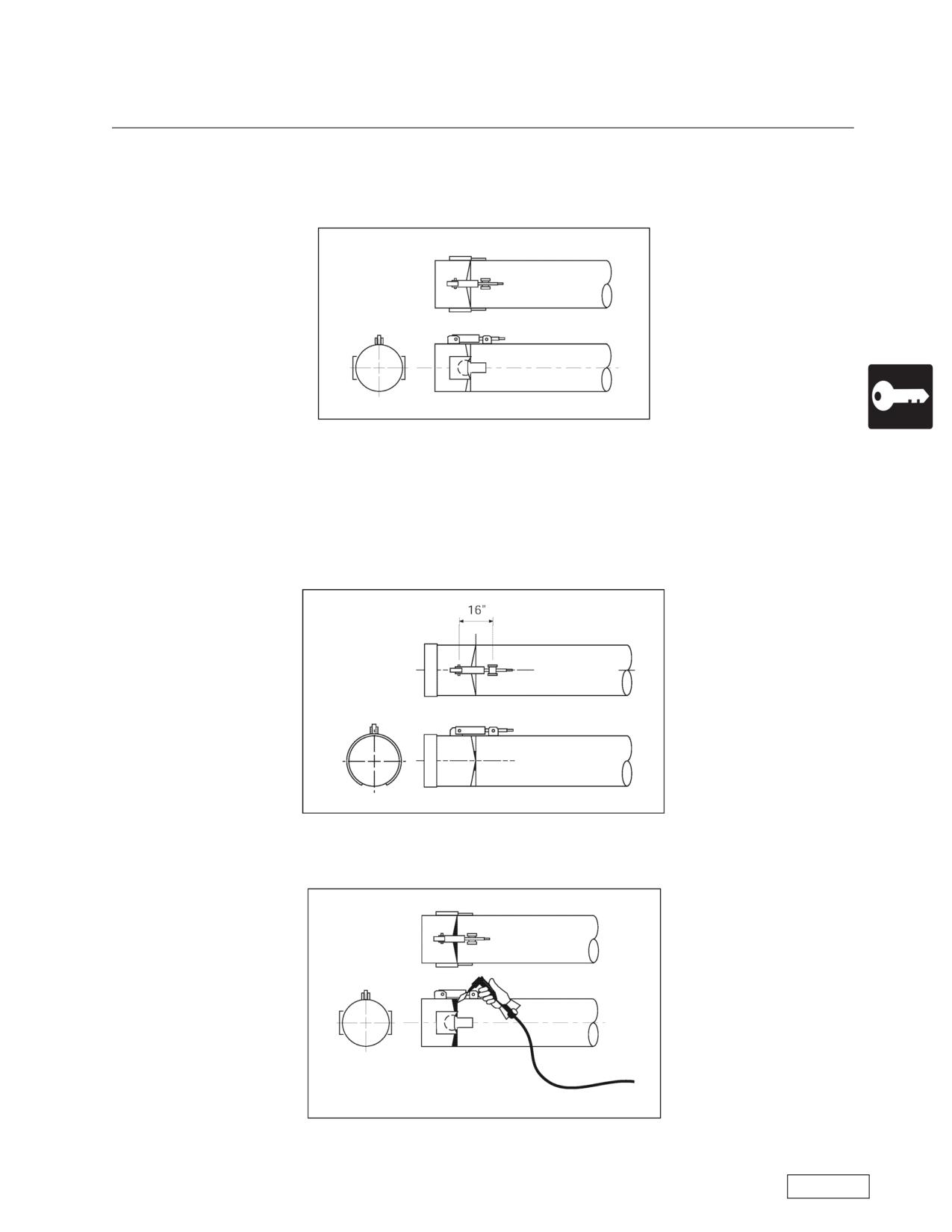
Boring Machine Operators Manual
Operations
Constructing the Steering Head
Step 6. After cutting the notches, position the hinge on the side center point so that the hinge cover and
knuckle are centered and the back of the cover is even with the vertical line of the notches previously cut.
Mark and cut out the place where the hinge will be attached. Insert the hinge so that it is flush with the inside
of the casing and weld in place thoroughly.
Step 6
Note standard hinge sizes:
10 -14 inch (25.4 - 35.6 cm)casing
3-1/2 inch (8.9 cm) hinge
16 -34 inch (40.6 - 86 cm) casing
7-1/2 inch (19 cm) hinge
36 inch (91 cm) and larger casing 9 inch (23 cm) hinge
Step 7. Adjust the steering knuckle so it has an equal amount of turns in and out. (Normally there will be
23 turns each way when centered correctly.)
Step 7
Step 8. After welding steering knuckle and hinges on, cut out remaining rectangle on top and bottom
(beneath steering knuckle).
Step 8
Refer to the Safety Awareness Program in this manual before attempting to operate this machine
Page 71
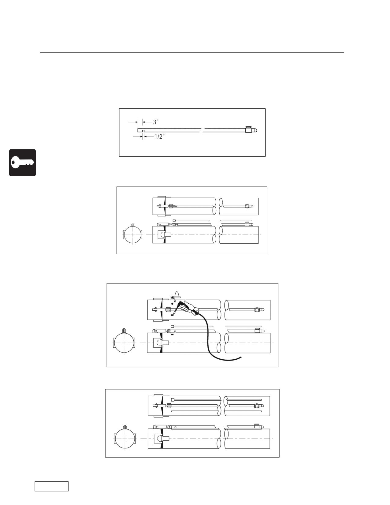
Operations
Boring Machine Operators Manual
Constructing the Steering Head
Step 9. (Optional) If lubrication is needed on the outside of the casing, there are two options
1) Cut a 1/2 inch (1.3 cm) slot in the piece of 1-1/2 inch (3.8 cm) pipe as shown. (The slot should only be
cut if planning on pumping bentonite around the outside of casing for lubricating the pipe as it travels through
the ground).
2) Set a separate 1/2 inch (1.3 cm) line parallel to the steering rods to lubricate the outside of the casing
with drilling fluid.
Step 9
Step 10. Make a steering pipe to fit inside the 1-1/2 inch (3.8 cm) cover pipe. (This steering pipe will be
shorter than all of the others. It will be between 16 -17 foot (4.9 - 5.2 m) in length).
Step 10
Step 11. Pierce a 3/8 inch (.95 cm) hole in the casing as shown on the left. Cut a slot to the left only if
able to pump water or bentonite inside the casing to facilitate spoil removal.
Step 11
Step 12. Weld the sensing head over the 3/8 inch (.95 cm) hole so that both holes are lined up together.
Step 12
Refer to the Safety Awareness Program in this manual before attempting to operate this machine
Page 72
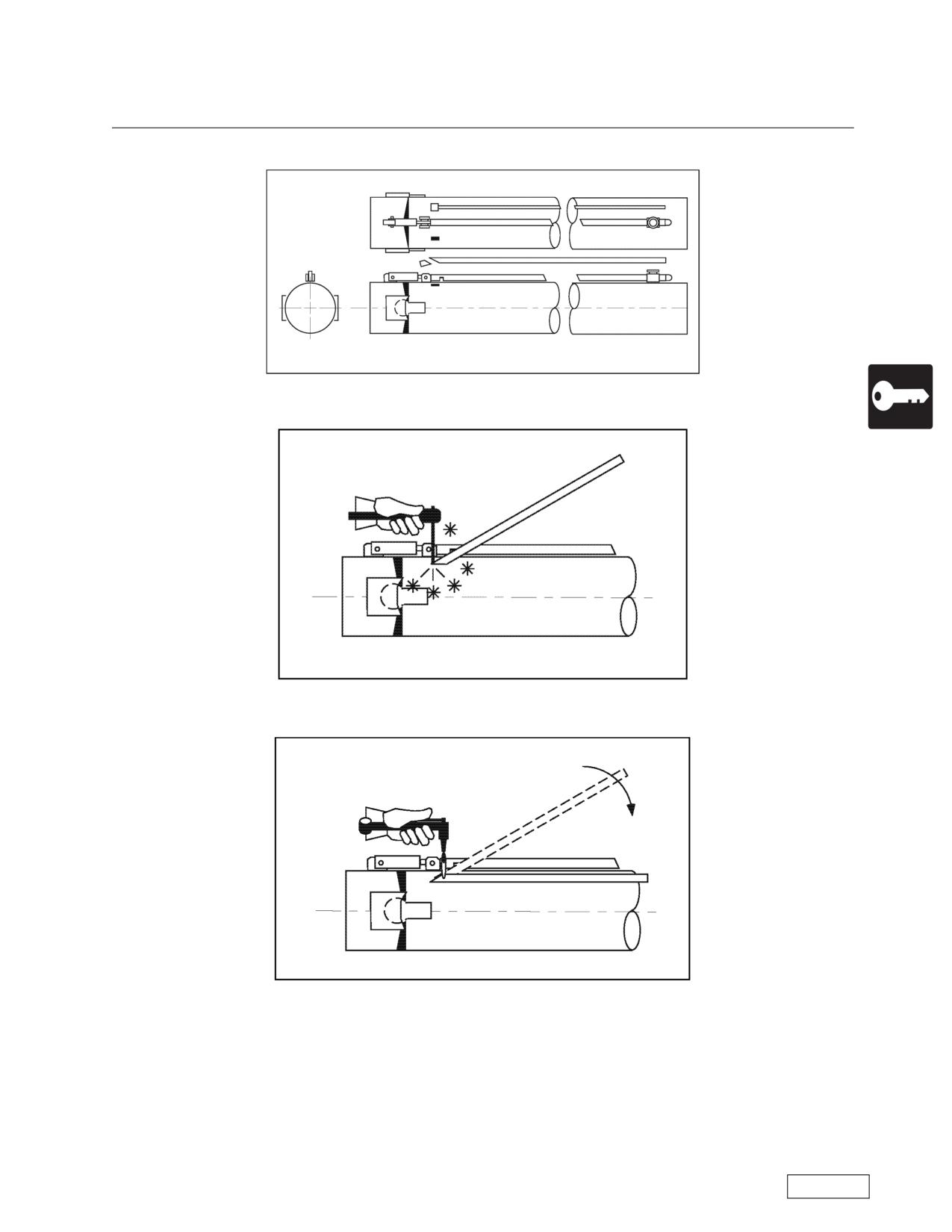
Boring Machine Operators Manual
Operations
Constructing the Steering Head
Step 13. Cut the end of the 1/2 inch (1.3 cm) pipe to form a bevel.
Step 13
Step 14. Weld the bevel over the slot formed in Step 11.
Step 14
Step 15. Heat the pipe and bend it to the top of the casing.
Step 15
Refer to the Safety Awareness Program in this manual before attempting to operate this machine
Page 73
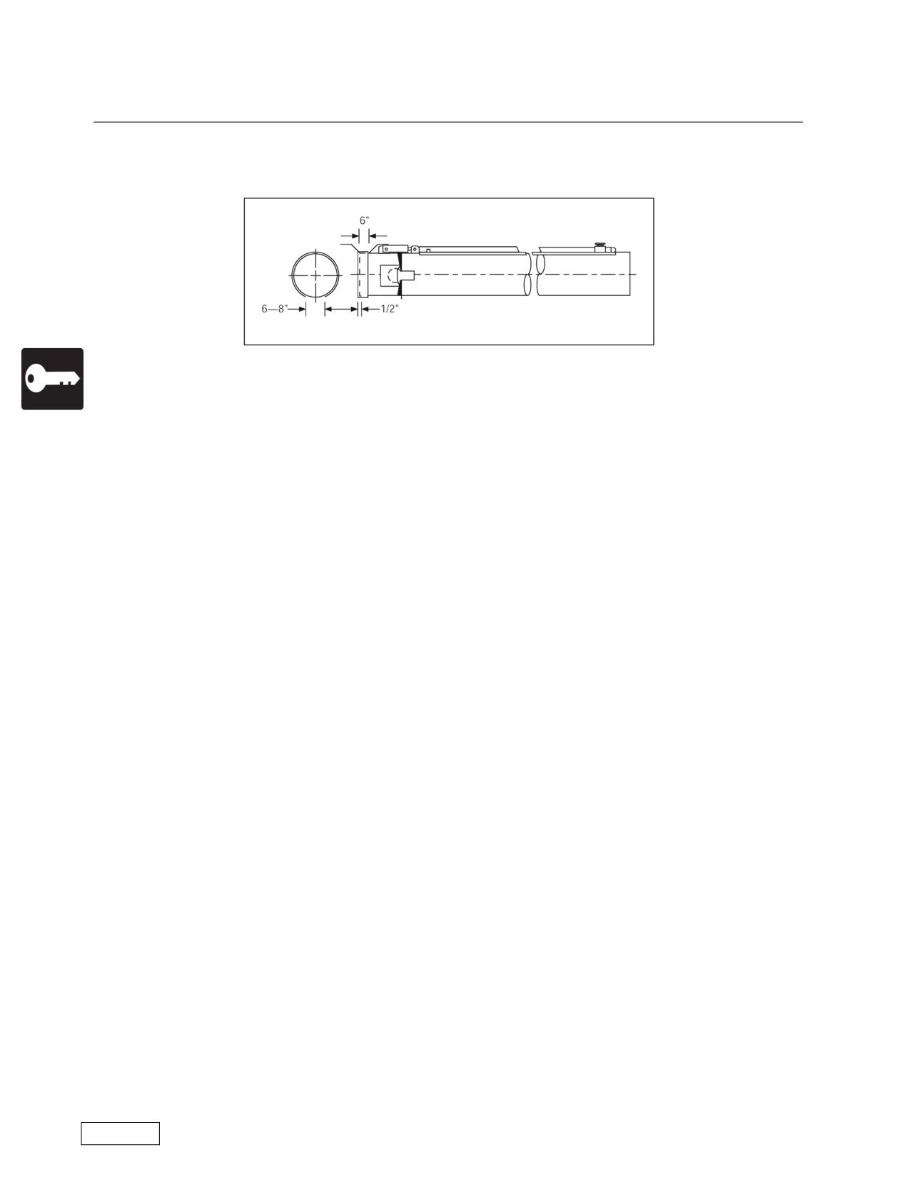
Operations
Boring Machine Operators Manual
Constructing the Steering Head
Step 16. Weld a 3/8 inch x 6 inch (.95 cm X 15.2 cm) ring around the front of the casing. (When running
a plug in front of the cutting head, a 12 inch (30.5 cm) wide ring would strengthen the front of the steering
head).
Step 16
Refer to the Safety Awareness Program in this manual before attempting to operate this machine
Page 74
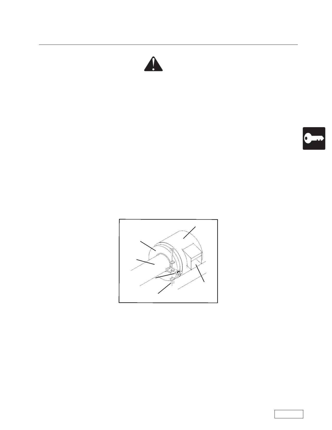
Boring Machine Operators Manual
Operations
Installing the Lead Casing and Auger in the Pit
DANGER
The observer must keep his body clear of the spoil chamber anytime the machine
engine is running. Rotating blades will cause amputation or death
Secure the auger in the casing before removing it from the truck. Lower the casing into the pit. Rest the
lead end of the casing in the saddle and align the auger shank with the machine chuck.
1. SHUT DOWN the machine engine. Open the spoil door. From a safe location, observe the alignment
of the hex coupling and the auger shank. Use of flashlight or mirror may help. Start the engine. Advance the
machine until the coupling is almost touching.
2. Slowly rotate the drive until the holes for the connecting pin align. Then carefully advance the boring
machine until the hex is fully seated and the casing is secure in the casing pusher. A cleaned, lubricated hex
will make the job easier.
3. Slowly rotate the drive until the hole for the connecting pin is visible to the observer. SHUT DOWN
the engine. For safety, remove the key from the ignition switch.
4. The observer can reach in through the spoil door and insert the connecting pin.
5. Start the engine and rotate the coupling 180° until the lower end of the connecting pin is visible.
6. SHUT DOWN the engine and remove the ignition key.
7. The observer installs a cotter pin in the lower end of the connecting pin to secure the pin during oper-
ation. CLOSE THE SPOIL DOOR.
8. Weld torque plates on the casing and secure them to the two bolt tabs on the master casing pusher
or casing adapter.
Casing Pusher
Casing Adapter
Casing
Torque Plate
(both sides)
Spoil Ejector
Bolt, Washer, Nut
Refer to the Safety Awareness Program in this manual before attempting to operate this machine
Page 75
Operations
Boring Machine Operators Manual
Case Boring Procedure
American Augers recommends that the following items be checked before starting the bore.
Job Setup
A) Pit walls adequately sloped or sheeted for safety in accordance with OSHA (29CFR1910)?
B) Machine & Casing on Line?
C) Machine & Casing on Grade?
D) Dutch Level located with enough chart to accommodate grade for length of bore?
E) Pit Sump Pump installed and operating properly?
F) Pit Area cleaned up?
Cutting Head & Casing
A) Measure and Record Outside Cutting Diameter Over Wing Cutters
B) Measure and Record Collapsed Head Clearance inside Casing
C) Cutting head teeth in condition for job?
D) Start Bentonite Pump-flow at leading end OK?
E) Mark casing in one foot increments starting at leading end
Boring Machine
A) Fluid levels in Machine
1) Engine Crankcase Oil
2) Transmission Gear Lube
3) Gearbox Gear Lube
4) Hydraulic Oil
5) Fuel
B) Spoil Door Closed?
Job Safety
A) Crew have any questions regarding safety or procedures with equipment being used?
Refer to the Safety Awareness Program in this manual before attempting to operate this machine
Page 76
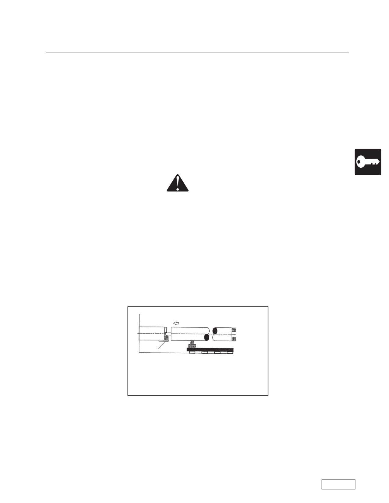
Boring Machine Operators Manual
Operations
Case Boring Procedure
Collaring
“Collaring” is the first operation in beginning a bore. The objective is to start the cutting head into the
ground without lifting the casing out of the saddle. This is done by rotating at low RPMs and using a slow
thrust advance. Let the saddle slip off the front of the track as the casing advances.When about 10 feet of
casing has entered the ground, SHUT DOWN the engine and check the line and grade of the casing. If the
casing is not running true, remove it and start again. The success of the bore depends upon the line and
grade of the first section of casing.
After the first section of casing has been installed in the ground, stop advancing and clean the casing by
rotating the auger until all the spoil is removed. (Exception: In sandy conditions or other runny materials, DO
NOT clean casing as this may create a void. Check the Ground Conditions Chart, in Appendix C, SHUT
DOWN the machine and remove the auger pin in the spoil chamber. Never push machine past the header
plate past the end of the track.
WARNING
It is an absolute rule that the machine engine is to be shut down before the spoil
door is opened to remove the pin from the auger drive. Rotating blades will cause
death or amputation.
Reverse the auger and pull back approximately 8 inches to have room to make the connection. Unbolt
and remove the torque plates, then move the machine back to the rear of the track and SHUT IT DOWN.
Lower the next section of casing and auger into position. Hold and align the casing until the augers at the
face are “timed,” flight-to-flight, and couple the hex joint. Block under the casing for support and relax the lift-
ing cables so there is no tension. Block the opening between the casing, and install the auger pin. When the
coupling has been secured remove the blocking, then weld "scabs" on the bottom of the installed casing at
4:00 and 7:00 o’clock positions (see drawing below.) Clear the area, and advance the casing over the auger
with the boring machine. Use heavy wood blocking between the machine and the casing and DO NOT
rotate the auger during this operation.
Scabs
Lower new section of auger into pit. Do not connect it to the
boring machine. Support the casing with blocking. Place the
blocking between the casing sections and between the new
casing and machine. Connect the auger sections.
Align the new casing with the installed casing by resting it on the “scabs”. Use of scabs beneath aligns
the inverts, which makes it easier to install carrier pipe later. Block the NEW casing at the machine end and
relocate the lift point back to the machine end. Lift in a cradle mode. Align the two casings using 4 feet (1.2
m) minimum length straight edges along the top and sides.
Refer to the Safety Awareness Program in this manual before attempting to operate this machine
Page 77
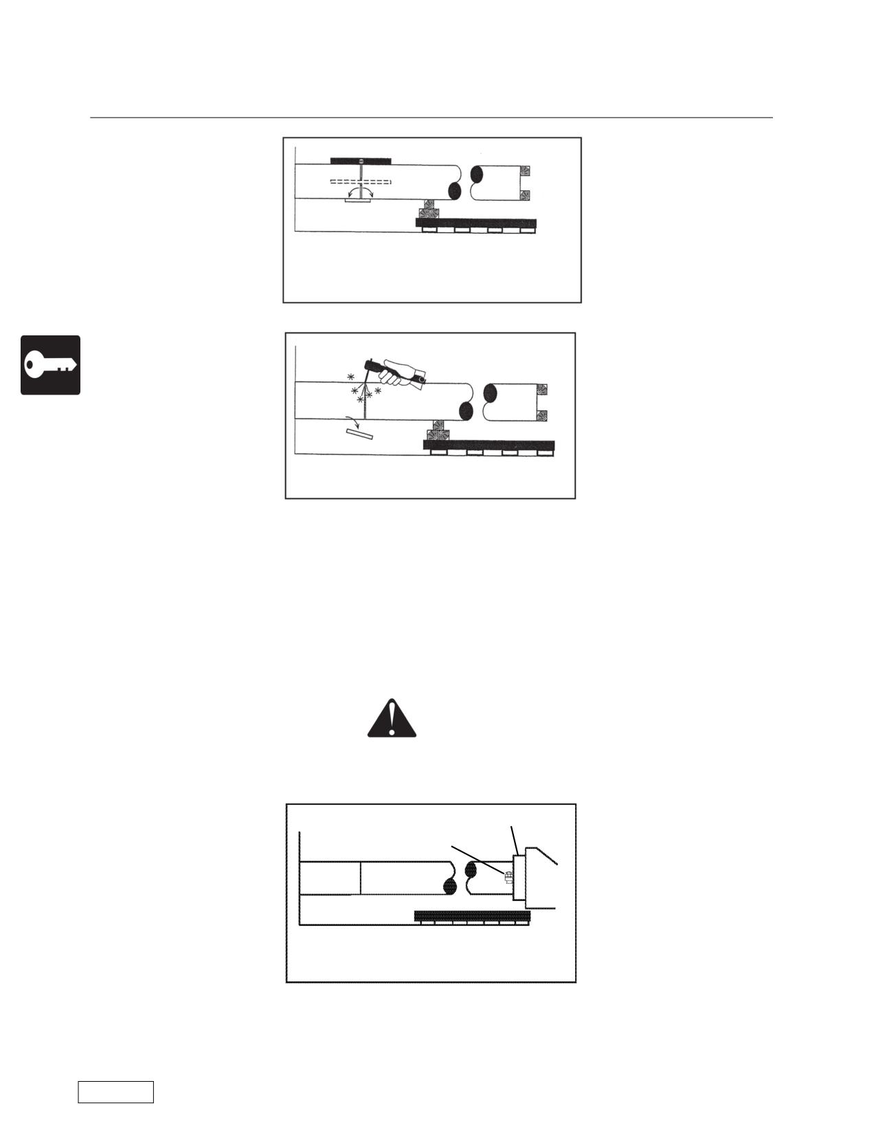
Operations
Boring Machine Operators Manual
Case Boring Procedure
First, align inverts of casing sections. Scabs help sup-
port new sections. Use 4 foot carpenters’s level to align
tops and both sides of casing.
Weld section together. Remove scabs
If the new casing is in line with the installed casing and seriously out of line at the machine end, the prob-
lem is in the installed casing and it must be corrected. If this condition is not correct, continuing the bore will
probably result in poor or unacceptable alignment of the completed casing installation. The new section of
casing is NEVER installed in the machine until the welding is complete. Tack the two casings together and
weld fully.
Start the machine and align the drive coupling with the auger hex and couple the drive. The operation
may require the spoil door to be open and a worker to direct the operator to align the hex coupling. The use
of a flashlight or mirror will allow the worker to be well away form the spoil chamber during the alignment.
DANGER
Before working inside the spoil chamber,
See safety information.
Casing Adapter
Weld torque plates to casing
Connect new casing to casing adapter of boring
machine.
SHUT DOWN the machine and install the auger pin.
Refer to the Safety Awareness Program in this manual before attempting to operate this machine
Page 78
Boring Machine Operators Manual
Operations
Case Boring Procedure
Secure the casing at the machine by welding torque plates to the casing and bolting to the Master Cas-
ing Pusher. Add the water and bentonite lines if being used. It is important that each new section of casing
be secured at the master casing pusher. This not only prevents the casing from turning, (which maintains
the accuracy of the Dutch Level), it also reduces the hazard of the machine upsetting if the auger or head
hangs up while boring. The weight of the casing, and the added resistance in the ground, will add to the sta-
bility of the machine. Clear the area, start the machine, and install the casing.
Continue the process until the bore has been completed. If it becomes necessary to remove the auger
and head during the bore to remove an obstruction or to service the head - refer to the section “REMOVING
AND INSTALLING AUGER WITH CUTTING HEAD ATTACHED,” (page 72).
Refer to the Safety Awareness Program in this manual before attempting to operate this machine
Page 79
Operations
Boring Machine Operators Manual
Preparing the Exit Pit
In most instances, an exit pit will be required at the end of the bore. The safety requirements for the exit
pit are the same as for the entrance pit.
If it is necessary to open the exit pit while the boring operation is being carried on, the entire perimeter of
the pit must be protected in the same manner as the entrance pit.
WARNING
Never allow a worker in the exit pit while the boring machine engine is running.
The rotating auger and cutting head can cause serious injury or death.
STAY AWAY.
The unexpected entry of the boring head into the pit can catch the worker and cause serious injury and,
in addition, there is a real danger of pit collapse as the casing approaches the exit pit.
When utility services have to be avoided, expose them and station an observer outside the protective
barrier to watch for the cutting head. A pair of two way radios is recommended for clear signaling. When
hand signals are used, make sure that both parties understand the signals and that traffic will not interfere
with the operation. When the head has entered the pit or has been located, the machine is to be SHUT
DOWN, and the key removed. Again, never allow personnel in the exit pit while the engine is running!
Refer to the Safety Awareness Program in this manual before attempting to operate this machine
Page 80
Boring Machine Operators Manual
Operations
Removing the Auger at the Completion of the Bore
WARNING
Rotating the auger while removing it from the casing increases the exposure of
workers to a rotating part.
Rotating auger and cutting head can cause death or serious injury.
Keep the area in front of machine clear of personnel when removing auger.
The following procedure is to be used when removing auger from the casing:
1. SHUT DOWN machine and remove key.
2. Remove the cutting head.
3. Clear the area, start the machine and clean the casing.
4. SHUT DOWN the machine and remove the torque plates.
5. Start engine, slowly rotate in the normal direction, and RETRACT the auger until the coupling is well
outside the casing.
6. SHUT DOWN the machine and remove the auger pin. Clear the area, start machine, back away from
the auger a short distance.
7. SHUT DOWN the machine and remove the auger section.
8. Clear the area and start the machine. ADVANCE the machine and couple to the auger.
SHUT DOWN the machine and install the auger pin. Clear the area and repeat steps 5-8 until all auger
sections have been removed.
Removing and Installing Auger with Cutting Head Attached
WARNING
Rotating the auger while removing it from the casing increases the exposure of
workers to a rotating part.
Rotating auger and cutting head can cause death or serious injury.
Keep the area in front of machine clear of personnel when removing auger.
WARNING
Rotating a head with wing cutters inside the casing increases the possibility of an
upset. Machine upset can cause death or serious injury. Never allow personnel,
other than the operator, to be on either side of the machine during this procedure.
The following procedure is to be used when removing auger WITH CUTTING HEAD ATTACHED:
1. Clear the area, start the machine and clean the casing.
2. SHUT DOWN the machine and remove the torque plates.
3. Start the machine, rotate the auger slowly in REVERSE at least 2 complete revolutions to collapse the
wing cutters, then slowly back the machine up to pull the cutting head inside the casing.
4. Retract the auger WITHOUT ROTATION, until the auger coupling is well inside the casing.
5. SHUT DOWN the machine and remove the auger pin. Clear the area, start the machine and back
away from the auger a short distance.
6. SHUT DOWN the machine and remove the auger section.
Refer to the Safety Awareness Program in this manual before attempting to operate this machine
Page 81
Operations
Boring Machine Operators Manual
Removing the Auger at the Completion of the Bore
7. Clear the area and start the machine. ADVANCE the machine and couple to the auger. SHUT DOWN
the machine and install the auger pin. Clear the area, and repeat steps 4-7 until all auger sections have
been removed.
The following procedure is to be used when installing auger WITH CUTTING HEAD ATTACHED:
1. SHUT DOWN the machine and examine and retool the head.
2. Clear the area, start engine, and ADVANCE until the coupling is one foot outside casing.
2a. It is not necessary to rotate in reverse unless one of the wing cutters has gotten caught on a weld
inside the casing. In that case, rotating in reverse would close the wing cutter.
3. SHUT DOWN the machine and remove the auger pin at the chuck. Clear the area, start the machine
and back the machine away from the auger. SHUT DOWN the machine and install the next auger section.
4. Repeat steps 2 and 3 until all auger sections are installed.
To Split The Machine
1. Unclamp swivel bolts that hold master pusher to base unit. Back up base unit clear of master pusher.
2. Shut down the engine and remove the key.
3. Unclamp the four corner swivel bolts that hold the upper and lower sections together.
4. Toggle the thrust control valve to relieve any pressure. Uncouple the hoses at the rear.
5. Uncouple the front half of the detented or bolt connected drive coupler by sliding it towards the gear-
box.
6. Attach the spreader bar chains to the upper set of lift points so that the lift will be level.
7. Gently remove the power package from the base unit by lifting vertically.
Refer to the Safety Awareness Program in this manual before attempting to operate this machine
Page 82
Boring Machine Operators Manual
Storage and Transportation
Storage and Transportation
Storage and Transportation
Minimum Storage Space Required
The space and load bearing capacity of the storgage area will vary with the size of the boring machine.
See the included table Auger Boring Machine Weights, Page 78.
Boring Machine Storage Dimensions
Track Length,
Height with sling,
Track Width,
Model
feet/inches
feet/inches
feet/inches
(m)
(m)
(m)
24/30-150
31 feet 1 inch
4 feet 7-5/16 inches
4 feet 6 inches
(9.5 m)
(1.4 m)
(1.4 m)
36/42-440
32 feet 7 inches
5 feet 6 inches
5 feet
(9.9 m)
(1.7 m)
(1.5 m)
36-600
31 feet 7 inches
5 feet 11 inches
6 feet 3 inches
(9.6 m)
(1.8 m)
(1.9 m)
42-600
31 feet 7 inches
5 feet 11 inches
6 feet 3 inches
(9.6 m)
(1.8 m)
(1.9 m)
48-900
31 feet 7 inches
6 feet 2-1/2 inches
6 feet 3 inches
(9.6 m)
(1.9 m)
(1.9 m)
48/54-900
35 feet 1 inch
6 feet 2-1/2 inches
5 feet 6 inches
(10.7 m)
(1.9 m)
(1.7 m)
60-1200
34 feet 1-1/2 inches
7 feet 6 inches
7 feet 6 inches
(10.4 m)
(2.3 m)
(2.3 m)
60-1200
35 feet 1-1/2 inches
7 feet 6 inches
7 feet 6 inches
(10.7 m)
(2.3 m)
(2.3 m)
72-1200
35 feet 1-1/2 inches
8 feet 4 inches
8 feet 4 inches
(10.7 m)
(2.5 m)
(2.5 m)
Refer to the Safety Awareness Program in this manual before attempting to operate this machine
Page 83
Storage and Transportation
Boring Machine Operators Manual
Storage and Transportation
Storage
• Clean all mud and other foreign materials off the machine.
• Position the machine on a level surface.
• Turn off the electrical system. On the 72-1200 Boring Machine turn off the electrical system by turning
the Battery Disconnect Switch to the OFF position.
For periods longer than 30 days:
• Follow steps to prepare machine for transport.
• Place the machine in a covered and dry site, and follow the instructions* for storing the engine.
• Disconnect batteries and store them where the temperature will remain between 32°F and 105°F (0°C
to 45°C).
• Eliminate sediment and water from the tanks (diesel fuel and oil). Top off all gear boxes.
Protect the machine from salty or acid environments, solvents, gas and flammable liquids and explo-
sives.
*Refer to: Attachment 1, Engine Manufacturer Manual.
Transport
WARNING
Transport of the machine must be carried out by trained and authorized personnel
only, after learning the information supplied in the manual.
Preliminary Operations for Transportation of the Machine
WARNING
Do not direct water spray inside the muffler or the air filter, against electric
components or control panels.
Clean all mud and other foreign materials off the machine.
Lifting the Boring Machine
Refer to the drawing on Page 17. Two sets of lift points are provided on split machines. The upper set,
located on the rack, is used to lift the power package out of the base push unit. It is NEVER used to lift the
entire machine. A second set of lift points is located on the base push unit. It can be used to lift either the
base unit alone or the entire machine. With either operation we recommend the use of a spreader bar as
shown.
CAUTION
Never use the upper lift points to lift the entire machine.
Refer to the Safety Awareness Program in this manual before attempting to operate this machine
Page 84
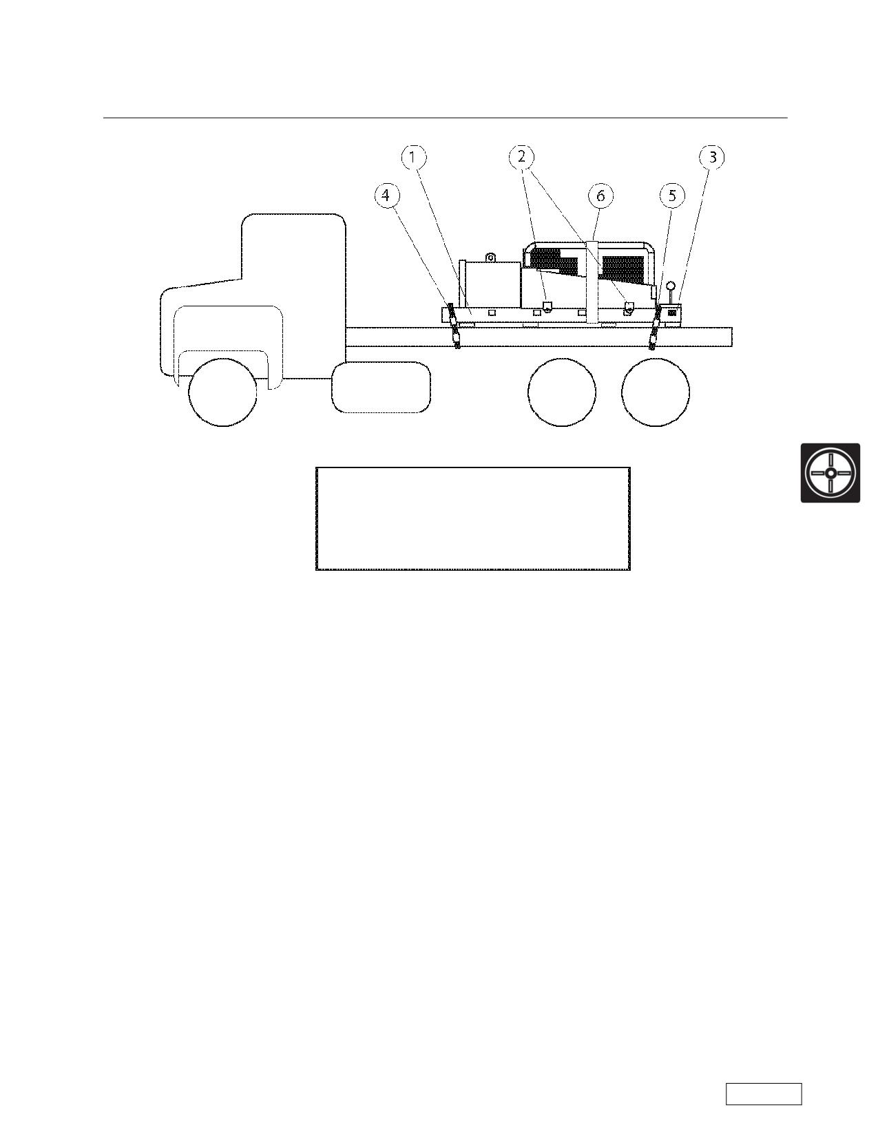
Boring Machine Operators Manual
Storage and Transportation
Storage and Transportation
NOTICE
Consult table to find weights of
components before lifting or
transporting
1) Boring machine must sit on master track
2) All hook rollers or hold downs must be down and locked.
3) Thrust block dogs must be engaged.
4) Pass chain over master track.
5) Pass chain between pushbar and base. Chain must not chafe on cylinder rods.
6) Strap or chain holds machine to track.
Refer to the Safety Awareness Program in this manual before attempting to operate this machine
Page 85
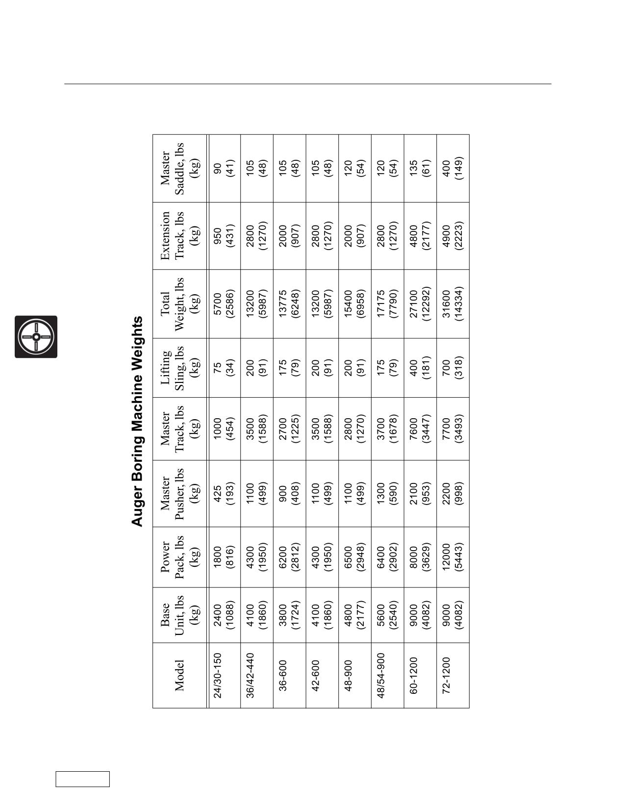
Storage and Transportation
Boring Machine Operators Manual
Storage and Transportation
Boring Machine Weights
Refer to the Safety Awareness Program in this manual before attempting to operate this machine
Page 86
Boring Machine Operators Manual
Maintenance
General Maintenance
Maintenance
It is impossible for a boring machine in poor condition to accomplish the same level of performance as a
well maintained piece of equipment. The operator should record (on each job) any items on the machine
that require repair. The operation of a boring machine that is in need of repair is discouraged by American
Augers.
WARNING
Do not modify your boring machine. This may
make the machine unsafe and will void the warranty.
When performing field or shop maintenance, it is important that the casing pusher and spoil paddles be
removed if the drive train is being tested. The shear point between the spoil paddles and the casing pusher
still presents the same hazard to a workman as it does when the machine is boring. Keep all guards in place
when possible, and keep all unnecessary personnel away from the machine during maintenance.
Inspection of the machine, augers, and cutting heads is impossible if the equipment is dirty. American
Augers recommends that the machine and equipment be cleaned with a high pressure washer after each job
so that an adequate inspection can be made. The American Augers Bentonite Pump is ideally suited for this
job. A clean machine can be inspected for damage. Repairs can be made immediately and much easier in
the shop rather than in the pit on the next job.
The Value of a Preventive Maintenance Program
a) Detecting problems early so minor problems can be repaired before they become major failures.
b) Monitoring maintenance schedules and practices in order to verify that maintenance is being done
and on time.
c) Scheduling downtime to fit into your work schedule.
d) Monitoring “positives” as well as “negative” so money isn’t wasted on early preventive maintenance.
e) Fluid analysis testing is quick and easy to do. Simply put, fluid analysis is one of the easiest and most
economical methods available to you to help prevent costly repairs and unscheduled downtime.
f) In addition, unplanned repairs, early replacement, and costly downtime need to be avoided.
g) Repair all hydraulic leaks once they are experienced or seen.
WARNING
Perform maintenance when there is no power to the machine and the controls.
Clean the machine and lock movable parts.
DANGER
Make sure personnel keep a safe distance during maintenance operations.
Refer to the Safety Awareness Program in this manual before attempting to operate this machine
Page 87
Maintenance
Boring Machine Operators Manual
General Maintenance
Hydraulic oil, gearbox oil, diesel engine oil, pin and bearing greases, diesel engine cooling liquid, battery
liquids and fuel should be handled with care. Consult Material Safety Data Sheets. Dispose of spent fluids
according to EPA and appropriate state and local regulations.
Engines, muffler, gearboxes and the hydraulic system can reach very high temperatures. Do not attempt
maintenance immediately after stopping work. Wait until the parts are cool.
Qualification of the Technician
The maintenance technician must be trained in boring machine operations. The maintenance technician
is responsible for conducting maintenance with suitable test and repair equipment, personal protective
equipment and attention to safety hazards. Any special repairs that cannot be made by the maintenance
technician should be reported to appropriate management personnel for prompt attention.
Welding
WARNING
Do not perform welding near the tanks and flammable liquids.
CAUTION
Failure to follow welding procedure can cause damage to electric and mechanical
components. Damage to components due to improper procedures is not covered
under warranty.
CAUTION
Disconnect ground terminal first.
Reconnect ground terminal last.
Welding must be done with the ground wire connected directly to the component where the weld is
made. Failure to follow the above instructions could damage electric and hydraulic components, cylinders,
gears and bearings due to internal arcing.
Cleaning
Cleaning Plastic and Resin Parts
Avoid using gasoline, kerosene, paint thinner and similar materials when cleaning the instrument cluster,
gauges, console, plastic windows, etc. These materials will cause discoloration, cracking or deformation of
the part being cleaned. Use ONLY water, mild soap and a soft cloth when you clean these parts.
Refer to the Safety Awareness Program in this manual before attempting to operate this machine
Page 88
Boring Machine Operators Manual
Maintenance
General Maintenance
Pressure Washing the Machine
CAUTION
Don’t direct the water spray inside the muffler or the air filter or against electric
components or control panels.
Approved Replacement Fluids
(Ambient temperature 0 Degree F to 110 Degree F [-18 Degree C to 44 Degree C])
Consult factory for specifications at low temperatures
Engine Oil
Shell Rotella™ T
AA Specification 401
Hydraulic Oil
Shell Tellus™ T ISO 46
AA Specification 202
Grease
Shell Retinax™ LC-2
AA Specification 301
Gear Lubricant
80W-140 Synthetic Gear Lubricant
API GL-5/AGMA-5EP
Engine Antifreeze
Shellzone™ 60%, Water 40%
AA Specification 601
To order fluids from other suppliers, consult the American Augers Lubrication Specifications.
Refer to the Safety Awareness Program in this manual before attempting to operate this machine
Page 89
Maintenance
Boring Machine Operators Manual
Scheduled Maintenance
Maintenance Schedule
Boring Machine Maintenance Schedule
After
10*
50*
500*
1000*
Function
each job hours
hours
hours
hours
Check Fuel Level
X
Check for Leaks
X
Electrical Systems
X
Gauges and Instruments
X
Check Emergency Stop and Safety Switches
X
Check Battery Water Level
X
Check Engine Crankcase Oil Level
X
Check Radiator Coolant Level
X***
Inspect Air Filter Stoppage Indicator
X**
Check Hydraulic Tank Oil Level
X
Check Hydraulic Oil Filters
X**
Tighten Tie Down Bolts on Split Machines
X
Lubricate Cam Followers
X
Check Transmission Fluid Level
X
Check Final Drive Fluid Level
X
Lubricate Push Bar moving parts
X
Tighten Bolts, Final Drive to Frame
X
Tighten Bolts, Transmission to Final Drive
X
Inspect Hoses
X
Lubricate Clutch Linkage
X
Change Transmission Fluid
X
Change Final Drive Fluid
X
Drain Hydraulic Tank and Replace Oil
X
Change Engine Oil and Filters
X,E
Perform Engine Maintenacne
X,E
Inspect Push Bar
X
Inspect Hydraulic Tank
X
Inspect and Lubricate Auger Couplings
X
Inspect Auger Sections
X
Inspect Cutting Heads
X
Check Operation of Controls
X
NOTES:
E, Consult engine manual on methods and
materials.
K, Consult pump manual on methods and materials
* Do not exceed the indicated number of hours
without performing the required maintenance
**, Unless filter indicator shows change required at
a more frequent interval
***, Not all Boring Machines have engines with radiators.
Refer to the Safety Awareness Program in this manual before attempting to operate this machine
Page 90
Boring Machine Operators Manual
Maintenance
Scheduled Maintenance
10 Hour Inspection and Maintenance
After 10 hours or before beginning operations, inspect and perform maintenance items as indicated on
the Maintenance Schedule.
Check fuel tank level. Tank should be full before starting operations.
Check all hydraulic hoses for frayed areas or damage and connections for leaks and repair as required.
Check electrical system for broken wires or connectors and repair as required.
Inspect gauges and instruments. Wipe the faces of gauges with a cloth moistened with water. Replace
cracked or missing glass. Fluid filled (shock resistant) gauges should be replaced if the glass is cracked.
Check emergency stop and safety switches. They should function perfectly.
WARNING
Machine batteries contain acid. Use proper precautions and follow the
instructions listed below.
Check the level of the electrolyte in the batteries and add distilled water if the level is too low.
Check the battery cables and verify that there are no abrasions or indentations; if necessary, replace the
battery cables. Check that the battery terminals are not corroded. Clean and replace them if necessary. The
voltage of the battery is 12 volts.
Clean corrosion off battery terminals. A paste made of sodium bicarbonate and water is normally enough
to clean terminals and battery box. After cleaning, rinse thoroughly with clean water. Coat the terminals with
grease in order to prevent future corrosion.
The batteries contain sulfuric acid. Protect eyes, face, and hands during maintenance work. Do not pour
battery acid on clothes, skin, or eyes. If the acid reaches the skin, flood with water. If the acid reaches the
eyes, wash with plenty of water and go to the doctor immediately. In case of ingestion, drink water or milk
and seek medical attention immediately.
Batteries can produce explosive gas. Do not smoke near a battery: keep away ignition source, sparks, or
flames. Charge the batteries only in well ventilated areas.
WARNING
Before checking or changing engine crankcase lube oil wait for the engine to cool.
Check oil levels in Engine Crankcase. Fill with grade oil recommended in engine manual provided. Refer
to: Attachment 1, Engine Manufacturer Manual and follow recommendations for operation and maintenance
to maintain your engine warranty.
WARNING
Before checking or changing coolant wait for engine to cool.
Check Radiator coolant level. Not all boring machine engines have radiators. However, on those engines
that do have radiators the coolant level should be checked. Fill with coolant recommended in engine manual
provided.
Refer to the Safety Awareness Program in this manual before attempting to operate this machine
Page 91
Maintenance
Boring Machine Operators Manual
Scheduled Maintenance
10 Hour Inspection and Maintenance
WARNING
Wait for engine to cool
Inspect air filter stoppage indicator. Change filter when indicated.
Check Hydraulic Reservoir oil level daily. Check with cylinders retracted. Fill to 2” of top with Premium
grade, antiwear hydraulic oil, with a viscosity index of 135 or higher.
WARNING
Wait for engine to cool
Check hydraulic oil filter gauge daily and change when gauge shows a pressure increase.
Several different types of hydraulic oil filters will be found in American Augers Boring Machines, depend-
ing on size and type of pump system. All will have an indicator, pressure gauge, or vacuum gauge to monitor
the oil flow and signal when the filter should be replaced or cleaned. The filter must be checked with the oil
at normal operating temperature.
(A) Suction Line: Vacuum gauge, 0-30 inches. At 8 inches Hg vacuum, the element should be dis-
carded and replaced with a new element.
(B) Return Line: Pressure gauge, 0-60 psi. At 12 psi, the element should be discarded and replaced
with a new element.
Check and tighten all tie down bolts on split machines before starting. Make periodic checks of tie down
bolts during operation.
Grease all cam followers daily with Shell Retinax™ LC-2.
WARNING
Wait for engine to cool
Check Transmission lube level. Fill to level plug with 80W-140 synthetic gear lubricant, meeting API GL-
5/AGMA-5EP.
Check Final Drive lube level. Fill to level plug with 80W-140 synthetic gear lubricant, meeting API GL-5/
AGMA-5EP.
NOTICE
Consult factory for recommended oil for operating in extreme low or high ambient
temperature
Refer to the Safety Awareness Program in this manual before attempting to operate this machine
Page 92
Boring Machine Operators Manual
Maintenance
Scheduled Maintenance
50 Hour Inspection and Maintenance
Perform 10 hour inspection and maintenance items, plus:
During Use:
Tighten all bolts holding the final drive to the frame.
Tighten all bolts in the coupling between the transmission and final drive.
Oil all Push Bar parts, including track dogs, weekly when in continuous use. A light machine oil is rec-
ommended. The push bar should be disassembled and cleaned periodically, especially after use in sticky
clay conditions.
Refer to the Safety Awareness Program in this manual before attempting to operate this machine
Page 93
Maintenance
Boring Machine Operators Manual
Scheduled Maintenance
500 Hour Inspection and Maintenance
Perform 10 and 50 hour inspection and maintenance items, plus:
Grease the linkage on both sides of clutch with Shell Retinax™ LC-2.
Drain old transmission oil into a proper container of appropiate size. Fill to level plug with with 80W-140
synthetic gear lubricant, meeting API GL-5/AGMA-5EP.
Drain old Final Drive oil into a proper container of appropiate size. Fill to level plug with with 80W-140
synthetic gear lubricant, meeting API GL-5/AGMA-5EP.
Drain hydraulic oil tank into a proper container of appropiate size. Refill to 2” of top with Premium grade,
antiwear hydraulic oil, with a viscosity index of 135 or higher. Draining and filling should be done with the cyl-
inders retracted. Hydraulic oil must also be replaced during year if it appears milky, indicating water in the
system.
Refer to the Safety Awareness Program in this manual before attempting to operate this machine
Page 94
Boring Machine Operators Manual
Maintenance
Scheduled Maintenance
1000 Hour Inspection and Maintenance
Perform 10, 50 and 500 hour inspection and maintenance items, plus:
Change engine oil and filters. Refer to: Attachment 1, Engine Manufacturer Manual for procedures.
Perform engine maintenance. Refer to: Attachment 1, Engine Manufacturer Manual for procedures.
Refer to the Safety Awareness Program in this manual before attempting to operate this machine
Page 95
Maintenance
Boring Machine Operators Manual
After Each Use
After Each Use
Wash down machine and inspect for damage.
Clean the Push Bar and disassemble. Inspect all parts and repair or replace as needed. Reassemble
and coat with a light machine oil.
Drain hydraulic oil tank into a proper container of appropiate size. Refill to 2” of top with Premium grade,
antiwear hydraulic oil, with a viscosity index of 135 or higher. Draining and filling should be done with the cyl-
inders retracted.
Clean and coat auger couplings with light grease after each use. Inspect shanks for twisting, replace if
there is evidence of failure.
Examine the auger sections after use for bent or broken flighting. Straighten and reweld as necessary.
Examine all teeth on the cutting heads and replace as necessary before each use. Inspect all bullet bits
on rock heads to insure they are firmly seated. Inspect condition of wing cutters; check for cutting diameter
and freedom of movement, as well.
Inspect operation of all controls, including Emergency Stop Control.
Refer to the Safety Awareness Program in this manual before attempting to operate this machine
Page 96
Boring Machine Operators Manual
Specifications
Specifications
Specifications
24/30-150 Specifications
Machine Dimensions / Weight
Length:
11 feet (3.4 m)
Width:
4 feet 6 inches (1.4 m)
Height:
4 feet 6 inches (1.4 m)
Estimated Weight:
5700 pounds (2586 kg)
Power Train
Engine:
Deutz F3L1011F Air-cooled, Diesel with electric start
Rating:
45 HP (34 kW)
Engine Speed:
2800 RPM
Engine Torque:
89 ft-lbs (121 N-m) @ 1800 RPM
Fuel Capacity:
10 U.S. Gallons (38 liters)
Transmission:
T-18, 4 Speed, Constant Mesh
Battery:
One, Deka 634MF, 12 volt, 690 CCA
Hydraulic System
Hydraulic Capacity:
14.5 U.S. Gallons (55 liters)
Maximum Thrust:
150,000 lbs (667 kN)
Torque and Speed
Torque Requirements: 1st Gear 26,268 ft-lbs (35,615 N-m)@2800 RPM Maximum Speed 60 RPM in
4th gear.
Miscellanous Performance Data
Working Range:
4 - 30 inch (102 - 762 mm) Casing Diameter
Hex Drive:
3 inch (76.2 mm) Hex
Spoil Door
With a Safety-First commitment, all American Augers horizontal earth boring machines are equipped
with a spring loaded-manual spoil door, which deflects thrown debris from the spoil chamber.
Refer to the Safety Awareness Program in this manual before attempting to operate this machine
Page 97
Specifications
Boring Machine Operators Manual
Specifications
36/42-440 Specifications
Machine Dimensions / Weight
Length:
12 feet 6 inches (3.8 m)
Width:
5 feet 3 inches (1.6 m)
Height:
5 feet 6 inches (1.67 m)
Estimated Weight:
13,200 pounds (5987 kg)
Power Train
Engine:
Deutz BF3L2011F Turbo Diesel
Rating:
57 HP (76 kW)
Engine Speed:
1600 RPM
Engine Torque:
129 ft-lbs (175 N-m) @ 1600 RPM
Fuel Capacity:
20 U.S. Gallons (76 liters)
Transmission:
T-18, 4 Speed, Constant Mesh
Battery:
One, Deka 634MF, 12 volt, 690 CCA
Hydraulic System
Hydraulic Capacity:
25 U.S. Gallons (95 liters)
Maximum Thrust:
440,000 lbs (1,512 kN)
Torque and Speed
Torque Requirements: 1st Gear 40,710 ft-lbs (55,195 N-m) @ 2800 RPM Maximum Speed 46.5 RPM
in 4th gear.
Miscellanous Performance Data
Working Range:
12 - 42 inch (305 - 1067 mm) Casing Diameter
Hex Drive:
4 inch (101.6 mm) Hex
Spoil Door
With a Safety-First commitment, all American Augers horizontal earth boring machines are equipped
with a gravity activated manual spoil door, which deflects thrown debris from the spoil chamber.
Refer to the Safety Awareness Program in this manual before attempting to operate this machine
Page 98
Boring Machine Operators Manual
Specifications
Specifications
36-600 Specifications
Machine Dimensions / Weight
Length:
13 feet (4 m)
Width:
6 feet 4 inches (1.9 m)
Height:
5 feet 3 inches (1.6 m)
Estimated Weight:
13,200 pounds (5987 kg)
Power Train
Engine:
Deutz D914L06 Turbo Diesel, Tier III
Rating:
115.9 HP (86 kW)
Engine Speed:
2300 RPM
Engine Torque:
276 ft-lbs (374 N-m) @ 1600 RPM
Fuel Capacity:
18.5 U.S. Gallons (70 liters)
Transmission:
Spicer 5-Speed, Constant Mesh
Battery:
One, Deka 634MF, 12 volt, 690 CCA
Hydraulic System
Hydraulic Capacity:
22.6 U.S. Gallons (86 liters)
Maximum Thrust:
600,000 lbs (2,669 kN)
Torque and Speed
Torque Requirements:1st Gear 88,604 ft-lbs (120,131 N-m)@2300 RPM/Maximum Speed 42 RPM in
5th gear
Miscellanous Performance Data
Working Range:
12 - 42 inch (305 - 1067 mm) Casing Diameter
Hex Drive:
4 inch (101.6 mm) Hex
Spoil Door
With a Safety-First commitment, all American Augers horizontal earth boring machines are equipped
with a gravity activated manual spoil door, which deflects thrown debris from the spoil chamber.
Refer to the Safety Awareness Program in this manual before attempting to operate this machine
Page 99
Specifications
Boring Machine Operators Manual
Specifications
42-600 Specifications
Machine Dimensions / Weight
Length:
13 feet (4 m)
Width:
6 feet 4 inches (1.9 m)
Height:
5 feet 3 inches (1.6 m)
Estimated Weight:
13,200 pounds (5987 kg)
Power Train
Engine:
Deutz D914L06 Turbo Diesel, Tier III
Rating:
115.9 HP (86 kW)
Engine Speed:
2300 RPM
Engine Torque:
276 ft-lbs (374 N-m) @ 1600 RPM
Fuel Capacity:
18.5 U.S. Gallons (70 liters)
Transmission:
Spicer 5-Speed, Constant Mesh
Battery:
One, Deka 634MF, 12 volt, 690 CCA
Hydraulic System
Hydraulic Capacity:
22.6 U.S. Gallons (86 liters)
Maximum Thrust:
600,000 lbs (2,669 kN)
Torque and Speed
Torque Requirements:1st Gear 88,604 ft-lbs (120,131 N-m)@2300 RPM/Maximum Speed 42 RPM in
5th gear
Miscellanous Performance Data
Working Range:
12 - 42 inch (305 - 1067 mm) Casing Diameter
Hex Drive:
4 inch (101.6 mm) Hex
Spoil Door
With a Safety-First commitment, all American Augers horizontal earth boring machines are equipped
with a gravity activated manual spoil door, which deflects thrown debris from the spoil chamber.
Refer to the Safety Awareness Program in this manual before attempting to operate this machine
Page 100
Boring Machine Operators Manual
Specifications
Specifications
48-900 Specifications
Machine Dimensions / Weight
Length:
13 feet (4 m)
Width:
6 feet 4 inches (1.9 m)
Height:
5 feet 3 inches (1.6 m)
Estimated Weight:
15,400 pounds (6958 kg)
Power Train
Engine:
Deutz TCD914L6 Turbo Diesel
Rating:
174 HP (130 kW)
Engine Speed:
2500 RPM
Engine Torque:
291 ft-lbs (395 N-m) @ 1600 RPM
Fuel Capacity:
18.5 U.S. Gallons (70 liters)
Transmission:
Eaton FS5205A
Battery:
Two, Deka 634MF, 12 volt, 690 CCA
Hydraulic System
Hydraulic Capacity:
22.6 U.S. Gallons (86 liters)
Maximum Thrust:
900,000 lbs (4,004 kN)
Torque and Speed
Torque Requirements: 1st Gear 113,087 ft-lbs (153,323 N-m) Maximum Speed 8 RPM
Miscellanous Performance Data
Working Range:
12 - 42 inch (305 - 1067 mm) Casing Diameter
Hex Drive:
4 inch (101.6 mm) Hex
Spoil Door
With a Safety-First commitment, all American Augers horizontal earth boring machines are equipped
with a gravity activated manual spoil door, which deflects thrown debris from the spoil chamber.
Page 101
Refer to the Safety Awareness Program in this manual before attempting to operate this machine
Specifications
Boring Machine Operators Manual
Specifications
48/54-900 Specifications
Machine Dimensions / Weight
Length:
15 feet (4.5 m)
Width:
5 feet 7 inches (1.7 m)
Height:
6 feet 2 inches (1.8 m
Estimated Weight:
17,175 pounds (7790 kg)
Power Train
Engine:
Deutz TCD914L6 Air-cooled Diesel
Rating:
174 HP (143 kW)
Engine Speed:
2300 RPM
Engine Torque:
373 ft-lbs @ 2300 RPM (506 N-m)
Fuel Capacity:
39 U.S. Gallons (148 liters)
Transmission:
Eaton FS-5205A
Battery:
Two, Deka 634MF, 12 volt, 690 CCA
Hydraulic System
Hydraulic Capacity:
22 U.S. Gallons (83 liters)
Maximum Thrust:
900,000 lbs (4,004 kN)
Torque and Speed
Torque Requirements: 1st Gear 108,832 ft-lbs (147,556 N-m)@ 2300 RPM Maximum Speed 59 RPM
in 5th gear.
Miscellanous Performance Data
Working Range:
24 - 54 inch (607 - 1372 mm) Casing Diameter
Hex Drive:
4 inch (101.6 mm) Hex
Spoil Door
With a Safety-First commitment, all American Augers horizontal earth boring machines are equipped
with a gravity activated manual spoil door, which deflects thrown debris from the spoil chamber.
Refer to the Safety Awareness Program in this manual before attempting to operate this machine
Page 102
Boring Machine Operators Manual
Specifications
Specifications
60-1200 Specifications
Machine Dimensions / Weight
Length:
13 feet (4 m)
Width:;
7 feet 3 inches (2.2 m)
Height:
6 feet 2 inches (1.8 m)
Estimated Weight:
27,100 pounds (12,292 kg)
Power Train
Engine:
Deutz TCD914L6 Turbo Diesel, water-cooled with electric start
Rating:
174 HP (130 kW)
Engine Speed:
2300 RPM
Engine Torque:
468.1 ft-lbs (635 N-m) @ 1600 RPM/373 ft-lbs (506 N-m) @ 2300 RPM
Fuel Capacity:
30 U.S. Gallons (118 liters)
Transmission:
Eaton 5205A
Battery:
Two, Deka 634MF, 12 volt, 690 CCA
Hydraulic System
Hydraulic Capacity:
66 U.S. Gallons (250 liters)
Maximum Thrust:
1,200,000 lbs (5,338 kN)
Torque and Speed
Torque Requirements: 1st Gear 108,832 ft-lbs (147,557 N-m) Maximum Speed 59 RPM in 5th gear
Miscellanous Performance Data
Working Range:
12 - 60 inch (305 - 1529 mm) Casing Diameter
Hex Drive:
5 inch (125 mm) Hex
Spoil Door
With a Safety-First commitment, all American Augers horizontal earth boring machines are equipped
with a gravity activated manual spoil door, which deflects thrown debris from the spoil chamber.
Page 103
Refer to the Safety Awareness Program in this manual before attempting to operate this machine
Specifications
Boring Machine Operators Manual
Specifications
72-1200 Specifications
Machine Dimensions / Weight
Length:
13 feet 9 inches (4.3 m)
Width:
8 feet 6 inches (2.6 m)
Height:
7 feet 5 inches (2.28 m)
Estimated Weight:
31,600 pounds (14,334 kg)
Power Train
Engine:
Caterpillar C7 ACERT, Tier III Diesel, water-cooled with electric start
Rating:
250 HP (186 kW)
Engine Speed:
2100 RPM
Engine Torque:
625 ft-lbs (847 N-m) @ 2100 RPM
Fuel Capacity:
58 U.S. Gallons (219 liters)
Transmission:
Eaton FS-6406A
Battery:
Two, Deka 634MF, 12 volt, 690 CCA
Hydraulic System
Hydraulic Capacity:
48 U.S. Gallons (181 liters)
Maximum Thrust:
1,200,000 lbs (5,338 kN)
Torque and Speed
Torque Requirements: 1st Gear 200,641 ft-lbs (271,868 N-m) @2100 RPM Maximum Speed 59 RPM
in 6th gear.
Miscellanous Performance Data
Working Range:
24 - 84 inch (610 - 2282 mm) Casing Diameter
Hex Drive:
5 inch (125 mm) Hex
Spoil Door
With a Safety-First commitment, all American Augers horizontal earth boring machines are equipped
with a gravity activated manual spoil door, which deflects thrown debris from the spoil chamber.
Refer to the Safety Awareness Program in this manual before attempting to operate this machine
Page 104
Boring Machine Operators Manual
Appendix
Appendix
Appendix
The appendix contains information that we believe the operator of the Horizontal Earth Boring
Machine will find useful to have available for reference during the operation of the Horizontal Earth
Boring Machine. The information is placed in the appendix because it is of general interest or it sup-
plements the information in the body of the manual.
Page 105
Refer to the Safety Awareness Program in this manual before attempting to operate this machine
Notes
Boring Machine Operators Manual
Notes
NOTES:
Refer to the Safety Awareness Program in this manual before attempting to operate this machine
Page 106
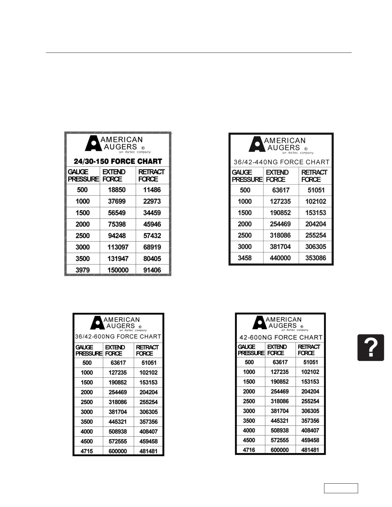
Boring Machine Operators Manual
Appendix A
Appendix A: Boring Machine Force Charts
Appendix A
English Units
24/30-150 Force Chart
36/42-440 Force Chart
36/42-600 Force Chart
42-600 Force Chart
Refer to the Safety Awareness Program in this manual before attempting to operate this machine
Page 107
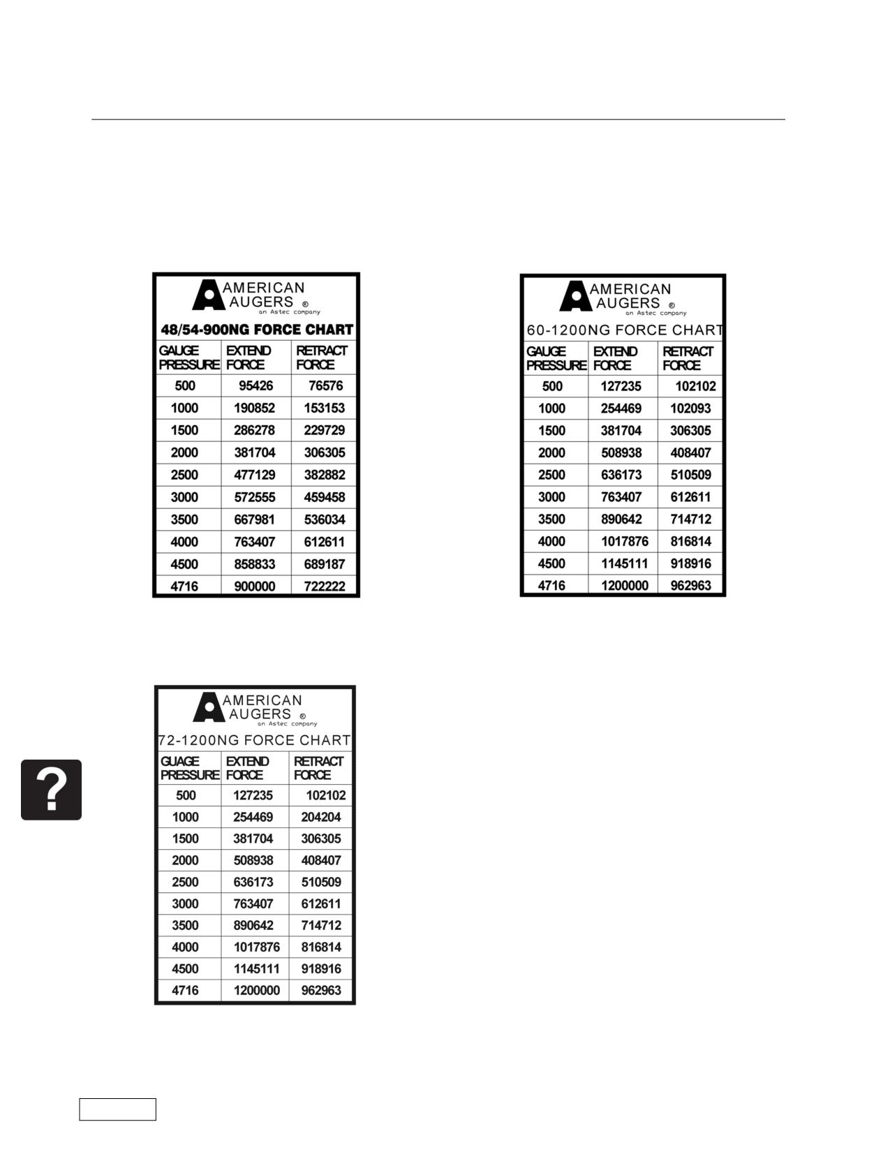
Appendix A
Boring Machine Operators Manual
Appendix A: Boring Machine Force Charts
English Units, Continued
48/54-900 and 48-900 Force Chart
60-1200 Force Chart
72-1200 Force Chart
Refer to the Safety Awareness Program in this manual before attempting to operate this machine
Page 108
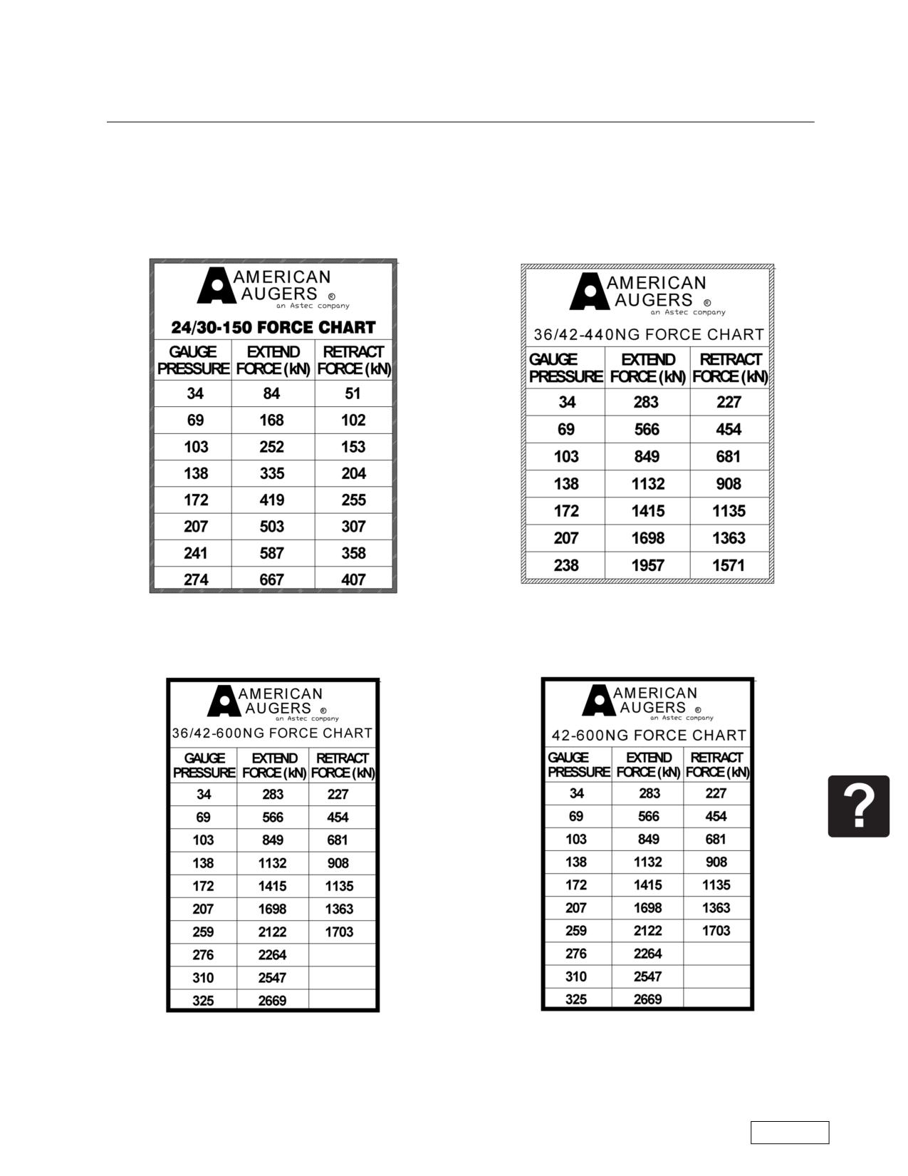
Boring Machine Operators Manual
Appendix A
Appendix A: Boring Machine Force Charts
Metric Units
24/30-150 Force Chart, Metric Units
36/42-440 Force Chart, Metric Units
36/42-600 Force Chart, Metric Units
42-600 Force Chart, Metric Units
Refer to the Safety Awareness Program in this manual before attempting to operate this machine
Page 109
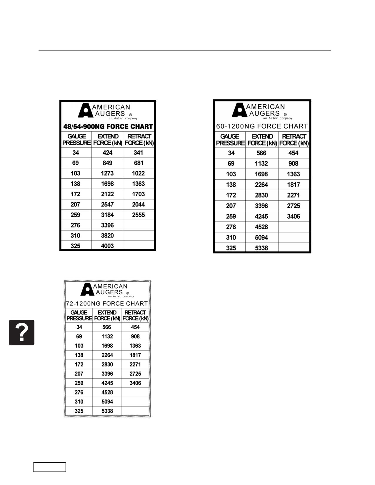
Appendix A
Boring Machine Operators Manual
Appendix A: Boring Machine Force Charts
Metric Units, Continued
48/54-900 and 48-900 Force Chart, Metric Units
60-1200 Force Chart, Metric Units
72-1200 Force Chart, Metric Units
Refer to the Safety Awareness Program in this manual before attempting to operate this machine
Page 110
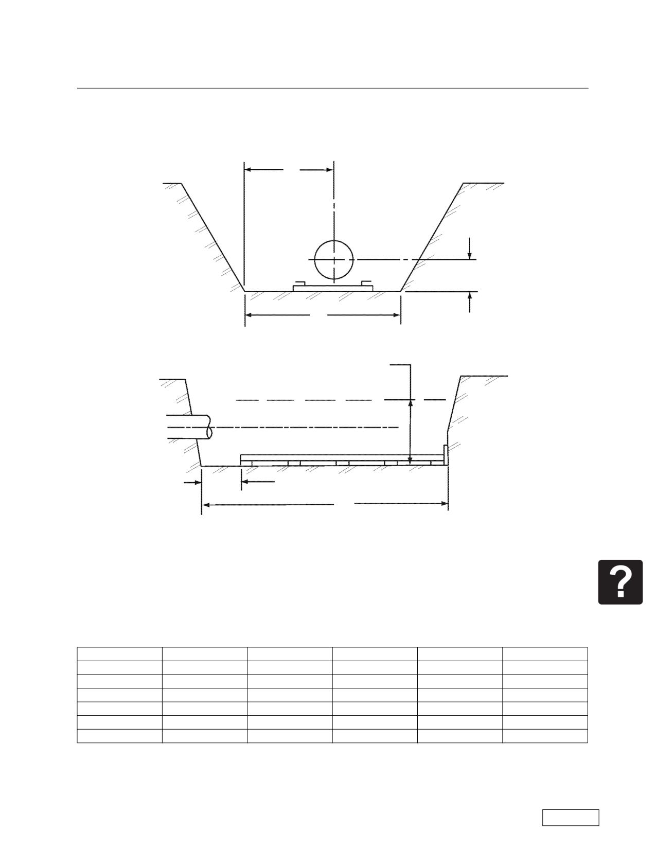
Boring Machine Operators Manual
Appendix B
Appendix B: Entrance Pit
Appendix B
Spoil Ejection
Side Offset
S
CL
W
Centerline
Pit Width
Overall Height
H
Track
Backstop
2 feet included in chart
L
Pit Length
Entrance Pit Chart
Minimum Dimensions for Installation of 20-Foot Length of Casing
Model
CL, inch (cm)
W, ft (m)
L, ft (m)
H, ft (m)
S, ft (m)
24/30-150
18.12 (46)
12'-0" (3.6)
35'-0" (10.4)
4'-9.25" (1.5)
7"-8" (2.3)
36/42-440
27 (76.7)
12'-0" (3.6)
35'-0" (10.4)
4'-9.25" (1.5)
7"-8" (2.3)
42-600
29.25
(83.1)
12'-6" (3.6)
35'-0" (10.4)
5'-2" (1.6)
8'-0" (2.4)
48-900
29.25
(83.1)
12'-6" (3.6)
35'-0" (10.4)
5'-2" (1.6)
8'-0" (2.4)
48/54-900
34 (96.6
12'-6" (3.6)
35'-0" (10.4)
5'-4.5" (1.6)
8'-0" (2.4)
60-1.2M
36.125 (102.6)
14'-0" (4.3)
35'-0" (10.4)
6'-2" (1.9)
9'-0" (2.7)
72-1.2M
36.125 (102.6)
15"-0" (4.6)
35'-0" (10.4)
6'-2" (1.9)
9'-0" (2.7)
These dimensions should be understood as general guidelines for pit dimensions. Use your engineering discre-
tion for the final entrance pit size.
Page 111
Refer to the Safety Awareness Program in this manual before attempting to operate this machine
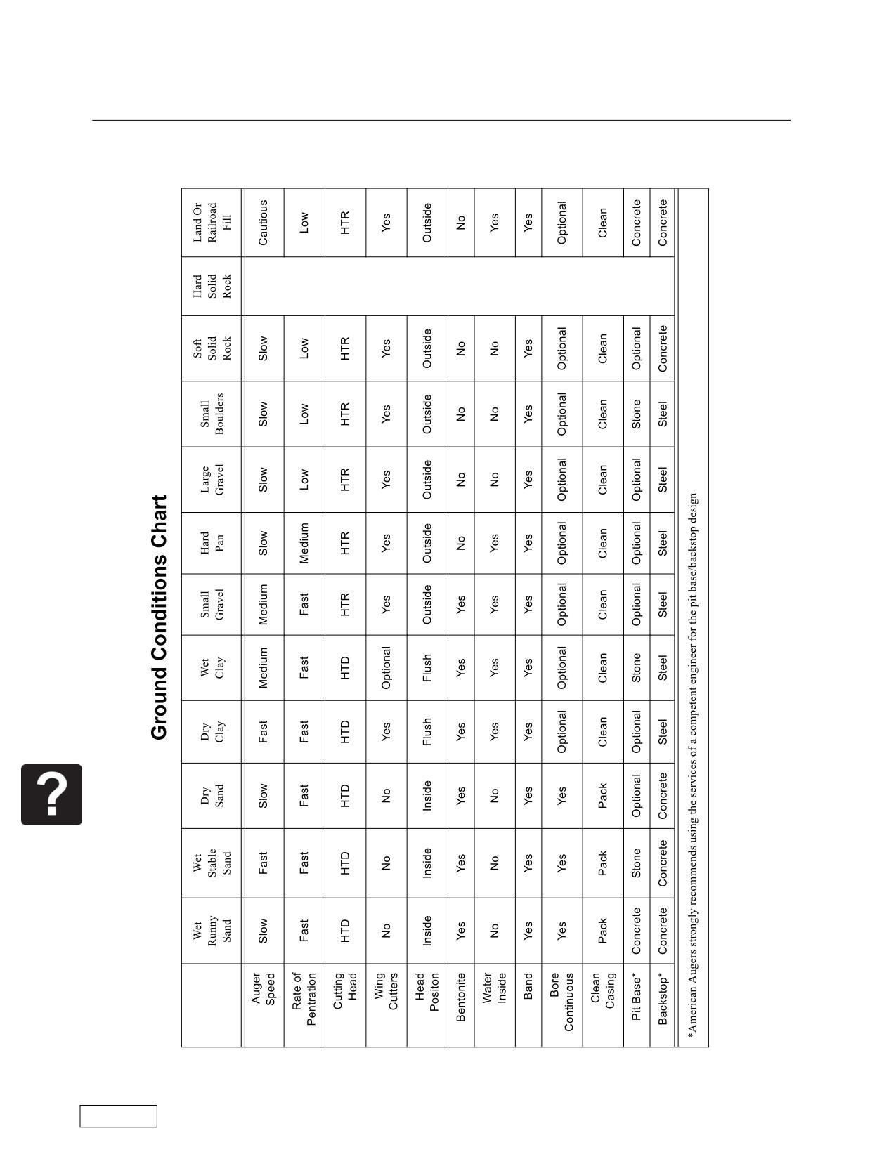
Appendix C
Boring Machine Operators Manual
Appendix C: Ground Conditions Chart
Appendix C
Refer to the Safety Awareness Program in this manual before attempting to operate this machine
Page 112
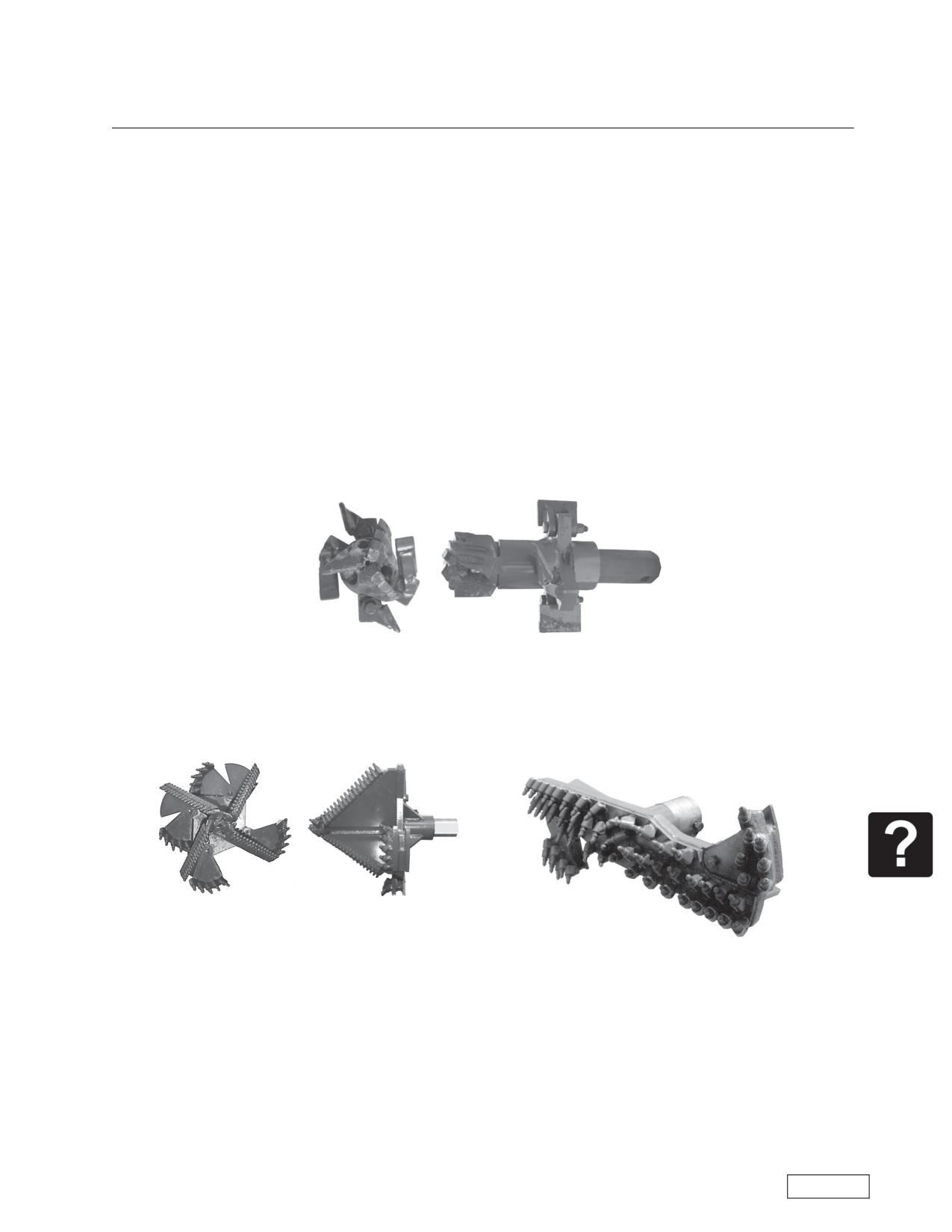
Boring Machine Operators Manual
Appendix D
Appendix D: Cutting Heads
Appendix D
American Augers manufactures Earth and Rock Cutting Heads - with and without wing cutters. Stock
heads are carried for general soil conditions. Special heads are available for specific conditions. See the
Ground Conditions Chart for cutting head recommendations for specific soil conditions
EFFECT OF WING CUTTERS
The function of wing cutters on a head is to overcut the tunnel, allowing the casing to enter more easily.
Wing cutters are used only in stable conditions as noted in the Ground Conditions Chart, Appendix C. Amer-
ican Augers wing cutters are preset to cut one inch (2.54 cm) larger than the nominal casing diameter. Large
diameter heads cut 1.5 inches (3.8 cm) over. The use of new or built up auger in the lead section of casing is
essential to maintain the proper centering of the head. Worn auger in the lead section will allow the head too
much freedom and the wing cutter pattern will be erratic. Wing cutters can, of course, be removed for oper-
ation of a head inside or outside of the casing.
HTD Head
Heavy Duty Rock Head (“Christmas Tree”) can be used
in place of the HTR head at the users preference.
HTR Head
Page 113
Refer to the Safety Awareness Program in this manual before attempting to operate this machine
Appendix E
Boring Machine Operators Manual
Appendix E: Auger Weight Charts
Appendix E
AUGER WEIGHT CHART
POUNDS PER FOOT
Casing Size
HEX SHANK SIZE in inches
in inches
1 3/8 (1/4 plt)
1 5/8 (1/4 plt)
2 1/4 (3/8 plt)
3 (3/8 plt)
4 (3/8 plt)
5 (1/2 plt)
4
7.0
6
7.5
7.9
8
8.5
8.9
17.8
10
10.8
19.7
37.3
12
11.9
22.1
39.9
14
12.7
24.1
41.7
16
15.5
27.2
45.1
57.0
18
17.7
31.3
48.8
60.7
20
20.7
35.7
52.1
65.1
24
45.0
62.4
74.8
96.5
30
61.2
79.5
90.8
116.5
36
79.2
95.9
106.7
139.8
42
117.1
127.7
167.9
48
142.4
152.6
199.1
54
181.0
236.7
60
212.6
278.7
72
286.0
375.7
Refer to the Safety Awareness Program in this manual before attempting to operate this machine
Page 114
Boring Machine Operators Manual
Appendix E
Appendix E: Auger Weight Charts
AUGER WEIGHT CHART
KILOGRAMS PER METER
Casing Size
HEX SHANK SIZE in millimeters
in mm
41.3
57.1
76.2
101.6
127.0
300
17.6
33.0
400
22.5
39.7
61.0
500
52.1
76.8
600
65.6
93.3
700
108.2
125.6
161.5
800
116.8
140.9
181.5
900
132.7
157.9
203.9
1000
160.6
176.5
230.7
1100
198.1
258.9
1200
222.2
288.7
1400
278.0
363.1
1800
415.2
552.1
1829
425.6
565.8
Page 115
Refer to the Safety Awareness Program in this manual before attempting to operate this machine
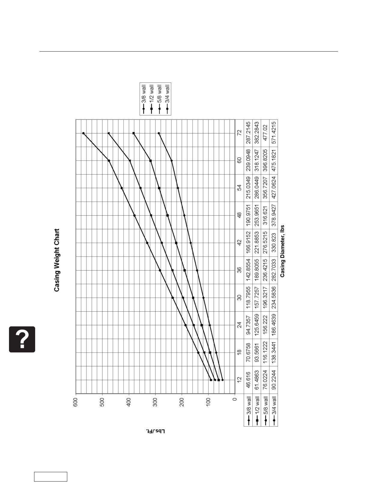
Appendix F
Boring Machine Operators Manual
Appendix F: Casing Weight Charts
Appendix F
Refer to the Safety Awareness Program in this manual before attempting to operate this machine
Page 116
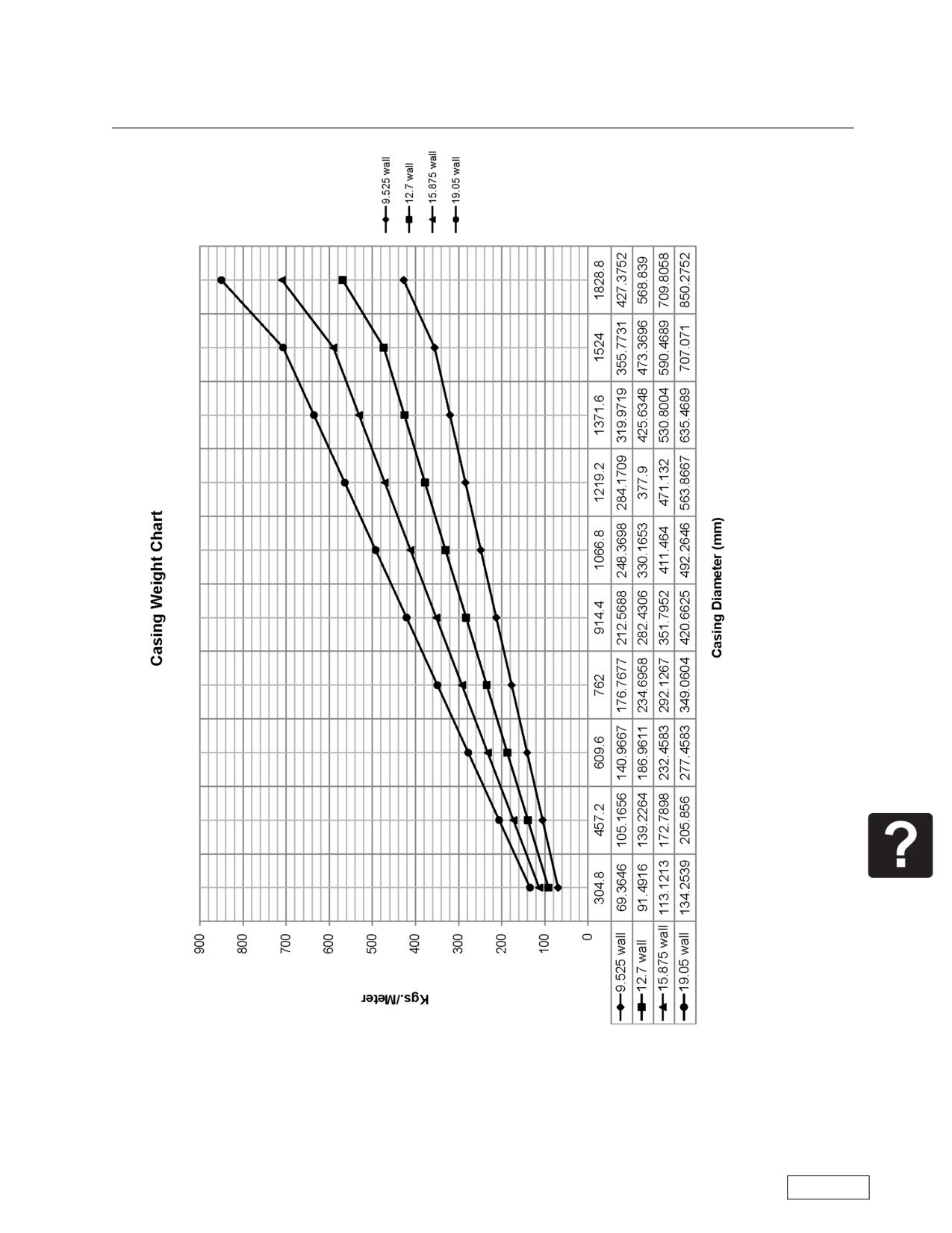
Boring Machine Operators Manual
Appendix F: Casing Weight Charts
Page 117
Refer to the Safety Awareness Program in this manual before attempting to operate this machine
Appendix G
Boring Machine Operators Manual
Appendix G: Boring Machine Glossary of Terms
Appendix G
A
ADVANCE: The motion of the machine in a direction toward the face wall of the entrance pit.
AUGER: A flighted drive tube having hex couplings at each end, to transmit torque to the cutting head
and transfer spoil back to the machine.
AUGER DRIVE: See DRIVE CHUCK.
B
BACKSTOP: Reinforced area of the entrance pit directly behind the track.
BAND: A ring of steel welded at or near the front of the lead section of casing to cut relief and strengthen
the casing.
BASE TRACK: See MASTER TRACK.
BENTONITE: A colloidal clay sold under various trade names that forms a slick slurry or gel when water
is added. Also known as drillers mud.
BITS: Replaceable cutting tools on the cutting head or auger.
BORING: The dislodging or displacement of spoil by a rotating auger or auger to produce a hole called a
bore.
BORING MACHINE: A mechanism to drill earth.
BORING PIT: See ENTRANCE PIT.
BOX : See FEMALE HEX CONNECTOR.
BUSHING: See FEMALE HEX CONNECTOR.
C
CAM FOLLOWER: A small diameter bearing wheel assembly.
CARRIAGE: The mechanical part of a non-split boring machine that includes the engine or drive motor,
the drive train, thrust block and hydraulic cylinders.
CASED BORING: The process of installing a casing in the earth while boring.
CASING: The steel pipe that is thrust into the earth by the boring machine.
CASING ADAPTER: A circular mechanism to provide axial and lateral support of a casing whose diame-
ter is smaller than that of the casing pusher.
CASING ATTACHMENT: See CASING ADAPTER.
CASING PUSHER: The front section of a boring machine that distributes the thrusting force of the
hydraulic cylinders to the casing and forms the outside of the spoil ejector system.
CENTERLINE: The vertical distance between the center of the drive chuck and the ground plane (bot-
tom of the track.)
CETANE: A measure of the ignition quality of diesel fuel.
CHIPPERS: See BITS.
CLEANING: An action of a boring machine that occurs when the auger is rotating while axially stationary.
CLUTCH: A mechanical device that engages or disengages rotary torque from a power source.
COLLARING: The initial entry of casing or a cutting head into the earth.
CONTROL LEVER: A handle that activates or deactivates a boring machine function.
CROSS MEMBERS: The lateral supports under the track.
CUTTING HEAD: An extension of the auger containing one or more bits to cut or dislodge earth.
D
DEAD MAN: A fixed anchor point used in advancing a saddle or cradle type boring machine.
DECK ASSEMBLY: Drive train assembly for a split design boring machine.
DEWATER: Any method used to lower the water table in the vicinity of the bore.
DOGS: Movable protrusions in the push bar that engage holes or blocks in the track.
DOG PLATE: see THRUST BLOCK.
DRILL PIPE: System of pipes used with cutting bit or compaction bit attached to the drive chuck.
DRIVE CHUCK: The female hex connector located within the casing pusher.
Refer to the Safety Awareness Program in this manual before attempting to operate this machine
Page 118
Boring Machine Operators Manual
Appendix G
Appendix G: Boring Machine Glossary of Terms
E
EMERGENCY STOP: A manually operated push button that when pushed stops all functions of the
machine.
ENTRANCE PIT: An opening in the earth of specified length and width for placing the machine on line
and grade.
EXIT PIT: An opening located at the expected exit of the cutting head or casing.
EXTENSION TRACK: An additional section of track used in front of the master track.
F
FACE: Wall of the entrance pit into which the bore is made.
FAST RESET: A hydraulic circuit which uses higher flow and lower pressure to reposition the thrust cyl-
inders.
FAST WORK: A hydraulic circuit that redirects flow to the thrust cylinders to increase the speed of exten-
sion.
FEMALE HEX CONNECTOR: A hexagonal shaped socket.
FINAL DRIVE: The final rotary speed reduction unit.
FLIGHT: The spiral plates surrounding the tube of an auger.
FLOW CONTROL: A hydraulic valve that regulates oil flow to the cylinders to change the speed of
advance.
FORWARD: The clockwise rotation of the auger as viewed from the machine end.
FREE BORING: The extremely dangerous practice of boring without casing.
FRONT DRIVE: See DRIVE CHUCK.
G
GEAR BOX: Planetary speed reduction. See FINAL DRIVE.
GEAR SHIFT: A lever for selecting transmission range.
GRADE: The specified rise or fall of the proposed bore from a horizontal plane. Calculated as rise ÷ run
x 100%.
GROUND PLANE: The surface upon which the machine is placed.
GROUT: A material such as a cement slurry, sand or pea gravel that is pumped into voids.
GUARD: A protective device fitted to the machine to minimize the possibility of inadvertent contact with
hazards.
H
HELICOID: A section of auger flight.
HEX DRIVE: See DRIVE CHUCK.
HOLD DOWN: A hinged or removable assembly that secures the boring machine to the track.
I
INADVERTENT CONTACT: Contact between a person and a hazard resulting from the person's
unplanned actions during normal operation or servicing of the machine.
INVERT: The elevation at the bottom of the casing.
K
KEEPERS: See HOLD DOWN.
L
LINE: The specified direction of the proposed bore in a horizontal plane.
M
MACHINE ROLLER: See CAM FOLLOWER.
MALE HEX CONNECTOR: See SHANK.
MASTER CASING PUSHER: See CASING PUSHER.
MASTER TRACK: The rear most track section.
MIXED FACE: A soil condition that presents two or more different types of material in the path of the
bore.
O
Page 119
Refer to the Safety Awareness Program in this manual before attempting to operate this machine
Appendix G
Boring Machine Operators Manual
Appendix G: Boring Machine Glossary of Terms
OPEN CUT: The method of digging a trench.
OPERATOR PRESENCE CONTROL: A control or mechanism designed so that operator presence is
necessary to activate a specific function.
P
PIERCING TOOL: An impact type of compacting device for boring with drill pipe.
PILING: Rigid supports driven vertically to provide wall support in the pit.
PINS: see SHANK.
PIPE PUSHER: A mechanical device used to produce a bore by means of compaction without rotation or
impact.
POWER PACKAGE: The engine and drive section of a split boring machine or the remote engine and
hydraulic pumps of a power unit.
PUSH BAR: See THRUST BLOCK.
PUSH BLOCK: See THRUST BLOCK.
PUSH PACKAGE: See THRUST PACKAGE.
Q
QUICK CONNECT FITTING: A type of fitting that allows making a hydraulic connection without the use
of wrenches.
QUIK TRAN: A rack-and-pinion drive system for moving the boring machine up and down the track
quickly.
R
RECEIVING PIT: See EXIT PIT.
RETRACT: The motion of the machine away from the face of the entrance pit.
REVERSE: The counterclockwise rotation of the auger as viewed from the machine end.
S
SADDLE: A vertical support mechanism to hold the casing In position while starting (collaring) the bore.
SADDLE ADAPTER: An attachment which fits on the saddle to support smaller casing.
SAFETY SIGN: A notice attached to the machine which advises the nature and severity of a potential
hazard which can cause injury or death. It can also provide instructions to reduce or eliminate the hazard.
SCAB: A piece of metal attached temporarily to aid with alignment.
SHANK: A hardened male hex bar containing of track used in front of the master track one or more
transverse holes to couple and hold in a female hex connector.
SHEET PILING: See PILING.
SHIELD: A guard that alone or with other parts of the machine provides hazard protection from the area
covered.
SHORING: See PILING.
SKIN FRICTION: Resistance to thrust caused by earth pressure around the casing.
SOCKET: See FEMALE HEX CONNECTOR.
SPEED REDUCER: See FINAL DRIVE.
SPLIT DESIGN: A boring machine having the capability of being broken down into two or more elements
to reduce the lifting weight.
SPOIL: Earth, rock and the like removed when making a bore.
SPOIL CHAMBER: See CASING PUSHER.
SPOIL EJECTOR: A set of paddles rotating in close proximity to the inside of the casing pusher.
SPOIL EJECTOR DOOR: A safety guard that partially or completely covers the spoil opening in the cas-
ing pusher.
STEERING HEAD: A movable section of the lead casing that can be adjusted to steer the bore.
SUMP: A depression in the pit to allow the installation of a pump for water removal.
Refer to the Safety Awareness Program in this manual before attempting to operate this machine
Page 120
Boring Machine Operators Manual
Appendix G
Appendix G: Boring Machine Glossary of Terms
T
TEETH: See BITS.
TEST BORE: Probing by auger or coring tool usually vertically at the site to determine the earth condi-
tions.
THRUST: The force which causes the boring machine to advance.
THRUST BEARING: An external bearing used to isolate the final drive from the thrusting force of the
machine.
THRUST BLOCK: A manual or remote operated locking mechanism that engages stations in the track to
provide a thrusting base for the machine advance and retraction.
THRUST BLOCK PIN: See DOGS.
THRUST PACKAGE: The bottom section of a split boring machine containing the cylinders and thrust
block.
THRUST PRESSURE GAUGE: The guage that displays the amount of hydraulic pressure used to thrust
the boring machine forward.
TORQUE: The measure of the rotary force available at the drive chuck.
TORQUE PLATE: Steel plates welded to casing and bolted to casing adapter to prevent the casing from
spinning.
TORQUE WINDUP: The energy stored when metal parts are held in a twisted condition. Release of this
energy can cause unexpected rotation of the auger.
TRACK: A set of longitudinal rails mounted on cross members that support and guide a boring machine.
TRACK BRAKE: A mechanical device to provide a limited resistance to movement between the machine
and the track.
TRACK PINS: Steel pins to be driven through holes in the track into the base of the pit.
TRACK ROLLER: See CAM FOLLOWER.
TRANSMISSION: A gear reduction unit located between the power source and final drive.
TRENCH BOX: A preconstructed set of side plates and adjustable cross members to prevent the walls of
the pit from collapsing.
TWO SPEED CONTROL: A hydraulic valve that increases the flow of oil to the cylinders to provide rapid
low power motion of the machine. See also FLOW CONTROL.
U
UPSET: The inadvertent action of a boring machine that rotates the machine and track from its normal
upright position to another position.
UNDERGROUND UTILITY: Active or Inactive services or utilities already in the ground in the area of the
proposed bore.
W
WALE, WALER: Heavy planks used as a brace.
WASTE EJECTOR: See SPOIL EJECTOR.
WATER LEVEL: An instrument that uses a tube filled with water to indicate the elevation of the lead sec-
tion of casing.
WATER TABLE: The elevation of the ground water.
WIND UP: See TORQUE WINDUP.
WING CUTTERS: Appendages on cutting heads that will open to increase the cutting diameter of the
head when turned in a forward direction and close when turned in a reverse
Page 121
Refer to the Safety Awareness Program in this manual before attempting to operate this machine