F65M MULTI PURPOSE MACHINING CENTER (2003)
September 9, 2003 Rev 0
F65M
MULTI PURPOSE MACHINING CENTER
MACHINE SERIAL NUMBER
___________________________
OPERATIONS AND MAINTENANCE
MANUAL
MANUFACTURED BY:
ROTTLER MANUFACTURING COMPANY
8029 South 200th Street
Kent Washington 98032
USA
Phone:
(253) 872-7050
Fax:
(253) 395-0230
Website: http://www.rottlermfg.com
NOTE: WHEN ORDERING REPLACEMENT PARTS,
PLEASE GIVE THE MODEL AND SERIAL NUMBER.
ORDER BY PART NUMBER.
THERE IS A MINIMUM ORDER OF $25.00
Table of Contents
1
F65 Manual
Chapter 1 Chapter 1 Introduction / Safety / Installation:
1-1
Introduction:
1-1
Description:
1-1
Limited Warranty:
1-1
Safety Information:
1-2
Electrical Power:
1-2
Machine Operator:
1-2
Emergency Procedure:
1-3
Machine Installation:
1-3
Location:
1-3
Unpacking and Lifting:
1-3
Type One:
1-4
Type Two:
1-4
Leveling and Alignment:
1-5
Leveling Locations:
1-6
Air Supply:
1-7
Grounding:
1-8
Electrical Enclosure:
1-9
Getting Started:
1-10
Shipping Restraints:
1-10
Spindle Support:
1-10
Counter-Weight Bar and Bolt:
1-10
Chapter 2 Chapter 2 Control Definitions:
2-1
Master Power On/Off Switch:
2-1
Power Air Draw Bar Switch:
2-1
Chapter 3 Chapter 3 Operating Instructions:
3-1
Loading a Block:
3-1
Performance Fixture 650-3-1 Boring:
3-1
Performance Fixture 650-3-1 Lifter Boring:
3-4
Lower End Machining Package 650-3-1A:
3-5
Block End Truing Fixture 650-3-30:
3-7
Block End Truing Fixture 650-3-30 when used with Cam Boring:
3-11
Cam Tunnel Boring:
3-12
V6/V8 Manual Fixture Assembly 502-1-72H:
3-14
Chapter 4 Chapter 4 Maintenance:
4-1
Lubrication
4-1
Manual Lubrication
4-1
Automatic Lubrication System
4-1
Power Draw Bar Lubrication:
4-2
Leveling and Alignment:
4-3
Leveling the Machine:
4-3
Alignment:
4-4
Middle Leveling Bolts:
4-7
Sweeping the Spindle:
4-9
Vertical Gib Adjustment:
4-11
Tightening Gibs:
4-11
Loosening Gibs:
4-11
Performance Fixture Line-Up:
4-12
Performance Fixture Line-Up (Cam End Tunnel Boring):
4-13
Chapter 5 Chapter 5 Troubleshooting:
5-1
Table of Contents
2
F65 Manual
Chapter 6 Chapter 6 Machine Parts:
6-1
F65 Front View:
6-1
Drive Motors and Switches:
6-2
F65 left Side View:
6-3
F65 Right Side View:
6-4
F65 Top View:
6-5
Electrical Panel:
6-6
F65 Control Panel:
6-7
Upper Belt Housing:
6-8
Options:
6-9
Performance Fixture 650-3-1:
6-9
Lifter Bore Spacers:
6-11
Application Chart:
6-11
Cam Bearing Locators:
6-12
Application / Selection Chart:
6-12
Main Bearing Locators:
6-13
Selection List:
6-13
Lower End machining Package 650-3-1A:
6-15
Block End truing Fixture 650-3-30:
6-16
2 ½” Wear pad Assembly 650-3-34:
6-17
Manual V6/V8 Combination Fixture 502-1-72H:
6-18
Boring Machine Application
6-18
V-blocks:
6-18
Y-Blocks:
6-18
Normal Operating Procedure:
6-18
Manual Fixture Assembly 502-1-72H:
6-20
V6/V8 Manual Fixture Body Assembly 502-1-72J:
6-21
V6/V8 Manual Fixture Body Assembly 502-1-72J: (cont)
6-22
Block Handler 502-1-95:
6-24
Dual Axis Leveling Table 7209M:
6-25
Adjustment Procedure:
6-30
Lubrication:
6-33
Universal Tooling Package 7119P:
6-34
Exhaust/Intake Manifold Surfacing Fixture Assembly 7226G:
6-35
Exhaust/Intake Manifold Fixture:
6-36
Instructions
6-36
Exhaust Manifolds
6-36
Typical Exhaust Manifold Set-up:
6-37
Typical Exhaust Manifold Set-up:
6-37
Intake Instructions:
6-38
Typical Intake Manifold Set-up:
6-39
Dual Axis Level Assembly 7125A:
6-40
½” Clamp Kit:
6-42
3 Dimensional Electronic Position Finder 502-9-9G:
6-43
Remote run-Out indicating System 502-12-7A:
6-44
Magnetic Indicator Holder 502-12-4:
6-45
Lifter Bore Tooling Package 650-2-20:
6-46
Additional Lifter Bore Tooling:
6-47
Quick Change Tap Holder Assembly 650-2-11J:
6-47
Torque Control Tap Holders:
6-48
Adapters NMTB 40 Taper:
6-48
Precision Drill Chuck Assembly 650-2-9:
6-48
2.9” Cutterhead:
6-49
2.9” Cutterhead Standard Tooling:
6-50
6520 Series Tool Holders
6-50
6598K Tool Bit when used with 6520 Holders
6-50
6260 SeriesTool Bit when used with 6520 Holders
6-50
6260 SeriesTool Bit when used with 6520 Holders
6-50
6547 Series Chamfering Tool Bits
6-51
Table of Contents
3
F65 Manual
when used with 6520 Holders
6-51
511-29-12D Torx Wrench
6-51
6598F Torx Wrench
6-51
6307F Micrometer Assembly
6-51
2.9” Cutterhead Optional Tooling:
6-52
6513 Series Grooving Tool Bits
6-52
when used with 6520 Holders
6-52
Cartridge Tool Holders:
6-52
6594 Cartridge Tool Holder:
6-52
Boring Inserts:
6-53
Boring Speeds and Feeds:
6-53
2.0” Cutterhead:
6-56
2.0” Cutterhead Standard Tooling:
6-57
6801 Series Tool Holders
6-57
511-29-12D Torx Wrench
6-57
511-29-12F Torx Wrench
6-57
501-72J Hex Driver
6-58
900-2-11 Micrometer Assembly
6-58
Boring Inserts:
6-58
Boring Speeds and Feeds:
6-58
Right Angle Drive:
6-61
6733A w/o Tooling
6-61
650-2-19A w/ Tooling
6-61
Right Angle Drive Tooling:
6-62
650-2-19 Line Bore Cutterhead:
6-62
6801 Series Tool Holders
6-62
Right Angle Drive Tooling:
6-63
650-2-19B Extended Range Line Bore Cutterhead w/ Tooling:
6-63
650-2-19C Extended Range Line Bore Cutterhead w/o Tooling:
6-63
6801 Series Tool Holders
6-63
Hex Driver 3/16” 501-72J
6-64
Torx Wrench 511-29-12D
6-64
Torx Wrench 511-29-12F
6-64
Micrometer Assembly 900-2-11
6-64
Boring Inserts:
6-65
Boring Speeds and Feeds:
6-65
Optional Main Line Bore Tooling:
6-66
6801 Series Tool Holders
6-66
10” Surfacing Head w/ Tooling:
6-68
14” Surfacing Head w/ Tooling:
6-69
Surfacing Inserts:
6-70
Surfacing Speeds and Feeds:
6-70
General Information:
6-71
2 ½” Shell Mill Assembly w/ Tooling:
6-72
4” Shell Mill Assembly w/ Tooling:
6-73
Complete Listing of NMTB 40 Taper Shell Mill Arbors:
6-73
Cam Line Boring Tooling Package:
6-74
1.9” Cutterhead:
6-74
1.9” Cutterhead Standard Tooling:
6-75
6802B Tool Holder
6-75
511-29-12F Torx Wrench:
6-75
501-72A Hex Driver:
6-75
900-2-11 Micrometer Assembly:
6-76
Oil Groove Tooling:
6-76
Boring Inserts:
6-77
Boring Speeds and Feeds:
6-77
Cam Locator Support:
6-78
Block Clamp:
6-79
Block Clamp Stud:
6-79
Table of Contents
4
F65 Manual
Adapter and Dual Flex Coupling Assembly:
6-79
Cam Line Boring Bar:
6-80
650-2-32D
6-80
Cam Line Bore Bushings:
6-80
Cam Line Boring Cartridges:
6-81
Tool Setting Indicator:
6-81
Wrenches:
6-81
Introduction / Safety / Installation
1-1
F65 Manual
Chapter 1 Introduction / Safety / Installation:
Introduction:
This manual is arranged in sections as listed in the table of contents.
It is required that the new user of the F65 Boring Machine read this manual before operation. Pay close
attention to the sections concerning safety.
The Controls Definition and Operating Instructions chapters should be read very carefully in order to
familiarize the user with the actual button pushing sequences required to carry out a job. These chapters
in the manual should be considered an introduction. As the operators of the F65 series machine gains
experience with using different functions of the machine, complicated setups and programs will make
more sense.
The rest of the manual contains information and part number reference on fixtures, cutting tools, and
machine maintenance. The operator needs to read and become familiar with these areas as well
Description:
The model F65 is a precision, single point, high speed boring machine. The F65 can be equipped with
tooling and accessories for re-boring most American passenger car and truck engines, In-lines as well as
60 and 90 degree V-types.
The F65 machines can be easily tooled to machines a wide range of engines, including European and
Asian.
The machine is designed to maintain the alignment of cylinder bores to the Pan Rails and Main Bearing
bore locations, as was done in the original factory machining. This overcomes the many inaccuracies
and out-of-alignment problems associated with the clamping of portable boring bars to the cylinder head
surface of the blocks.
Convenient controls, fast block clamping, air floated Spindle Base positioning and clamping, means
considerable savings in floor to floor time and operator involvement.
Change over or re-setting time required to set up V-type or In-Line engines is a minimum, making this
machine highly suited to the jobber shop where engines cannot be run through in model lots.
Limited Warranty:
Rottler Manufacturing Company Model F65 parts and equipment is warranted as to materials and
workmanship. This limited warranty remains in effect for one year from the date of delivery, provided the
machine is owned and operated by the original purchaser and is operated and maintained as per the
instructions in the manual.
Tools proven to be defective within the warranty period will be repaired or replaced at the factory’s option.
We accept no responsibility for defects caused by external damage, wear, abuse, or misuse, nor do we
accept any obligation to provide compensation for direct or indirect costs in connection with cases
covered by the warranty.
Freight charges on warranty items (non-air shipment only) will be paid by Rottler Manufacturing for a
period of 60 days only from the date of installation or set-up by a qualified service technician or sales
representative.
Freight charges after the 60 day period are the customer’s responsibility.
Introduction / Safety / Installation
1-2
F65 Manual
Safety Information:
CAUTION: This machine is capable of causing sever bodily injury!
The operator of the F65 should be a skilled machinist craftsman who is well versed in the caution, care,
and knowledge required to safely operate metal cutting tools. Eye protection must be worn at all times
by the operator and all other personnel in the area of the machine.
The operator should be extremely cautious when working around the cutting tool area.
When boring the machine is capable of throwing metal chips over 10- feet from the cutting area. Always
use the guards.
The F65 operates under computerized control and, as is all computerized equipment, is susceptible to
extraneous electrical impulses internally for externally produced. The machine may make moves out of
the operator control at any time. The operator should work in and around the machine with caution at all
times.
The operator and nearby personnel should be familiar with the location and operation of the Emergency
Stop Button.
Electrical Power:
Make sure all electrical equipment has the proper overload protection. The F65 should have a fully
isolated power supply to prevent damage and uncontrolled movement of the machine. If the F65 is on
the same power lines that are running to other electrical equipment (grinders, welders, and other AC
motors) electrical noise can be induced into the F65 electrical system. Electrical noise can cause the
controller to see false signals to move. Not supplying a fully isolated supply to the machine may void
factory warranty. Refer to the Power supply section later in this chapter for voltage and amperage
requirements of the F65.
Machine Operator:
The operator of the F65 should be a skilled machinist craftsman who is well versed in the caution, care,
and knowledge required to safely operate metal cutting tools. Eye protection must be worn at all times
by the operator and all other personnel in the area of the machine.
If the operator is not a skilled machinist he/she must pay strict attention to the Operating Instructions
outlined in this manual, and get instruction from a qualified machinist in both production and operation of
this machine.
The F65 machines have the following areas of exposed moving parts that you must train yourself to
respect and stay away from when they are in motion:
1. Tool Sharpening - Must be done with care and dexterity to get good bore results, be alert to
the light pressure required for tool sharpening.
CAUTION: Exposed diamond wheel is a potential hazard to your hands, fingers, and face. Eye
protection must be worn when working in this area.
2. Cutting Tool Area - Any operation involving hands in the cutter head area, such as
inspection or alignment of the cutter head or tools, changing Centering Fingers, tool insertion,
and removal, cutter head changes, and size checking etc. requires the machine to be in
Neutral.
3. Machining - Eye protection must be worn during all operations of the machine. Hands must
be kept completely away from the cutter head. All chip guards must be in position during
machine operations.
Introduction / Safety / Installation
1-3
F65 Manual
4. Work Loading and Unloading - Carefully develop handling methods of loading and
unloading work pieces so that no injury can result if hoist equipment or lift connection should
fail. Periodically check lift components for damage that may cause failure of Block Handler
Assembly. Lifting Eye can eventually fail if the eye is reset in line with the 502-1-80 lift
channel. Eye must be at a right angle.
5. Machine Maintenance - Any machine adjustment, maintenance or parts replacement
absolutely requires a complete power disconnection from the machine, this is an absolute
rule.
Emergency Procedure:
Assuming one of the following has occurred: tool bit set completely off size, work piece or spindle base
not clamped, spindle is not properly centered, these mistakes will become obvious the minute the cut
starts
PRESS THE EMERGENCY STOP BUTTON (on the front control panel) IMMEDIATELY!
Find out what the problem is; return the spindle to its up position without causing more damage. To
restart the machine, turn the Emergency Stop Button CW until the button pops out. Make sure the button
has been depress for at least 1 ½ minutes or the drive will not have time to reset and they will not
function.
Be alert to quickly stop the machine in the event of a serious disruption of the boring process either at the
top or bottom of the bores.
“REMEMBER” metal cutting tools have the speed and torque to severely injure any part of the
human body exposed to them.
Machine Installation:
Location:
The productivity of the F65 will depend a great deal on the proper initial installation. Pay particular
attention to the means by which work pieces are lifted into and out of the machine as well as the material
handling to and from other operations in your shop. The proper loading arrangements and work location
for your F65 is extremely important.
A slow travel (6’ to 10’ per minute) power hoist, operated from either a bridge or jib crane arrangement
works very well. A 1000 lb. Is generally adequate for lifting most engine blocks. An air hoist with speed
control makes an ideal method for fast, efficient loading and unloading.
For shops where large production runs are anticipated, the work pieces should be loaded and unloaded
directly from a conveyer. If this is not the case, we suggest you pay considerable attention to the crane
so that it covers an adequate area to allow the operator to back up and remove work pieces without
creating a cluttered, dangerous work area.
Unpacking and Lifting:
Use care when removing the crate materials from the machine. Be careful not to use force on any part of
the machine.
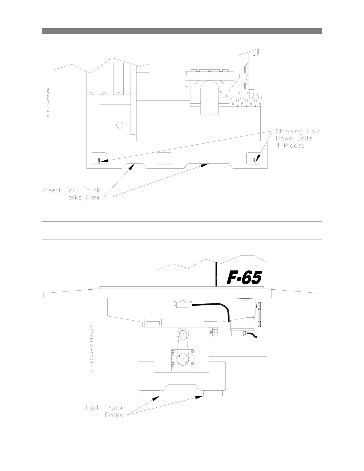
Remove the Nuts and Jam Nuts from the Four (4) bolts holding the F65 to the crate. These bolts are
located at the four bottom corners of the Main Base.
You will need a Fork Truck with a minimum of 8,000 lb. Capacity. The F65 can be picked up from the
pallet in two (2) different ways. See the following page for illustration of these procedures.
Introduction / Safety / Installation
1-4
F65 Manual
Type One:
Be sure that the forks are at least Four inches through the opposite side of the casting.
CAUTION: This machine is extremely top heavy. Use extreme care whenever this machine is being
used. Do not use quick or sharp movement.
Type Two:
Introduction / Safety / Installation
1-5
F65 Manual
Remove the Toolbox, Parallels and optional equipment form the machine. Completely clean these
articles along with the rest of the machine with solvent, rust inhibitor was applied at the time of shipment.
Any of the rust inhibitor left on the machine will allow Cast Iron dust to build up and cause premature wear
to the machine.
IMPORTANT:
The ways under the table as well as the ways behind the Vertical gibs were sprayed with rust
inhibitor as well. It is extremely important that these surfaces be cleaned thoroughly. Use a
cleaner, such as WD-40 to clean the ways where the table and the spindle unit are not sitting.
Move the table and spindle unit onto the area that has been cleaned and clean where they were
sitting. Spray the ways with WD-40 and move the table and spindle unit over the sprayed area.
You must do this several time to get all of the rust inhibitor off of the gib surfaces. If you do not
the rust inhibitor will plug up the oiler holes and also cause sticktion when moving in small
increments, such as handwheel.
Leveling and Alignment:
Leveling the F65 properly is very important if you are to use the F65 to its full blue printing capabilities as
well as maximizing the use of Rottler fixturing.
Use the following instructions to properly level the F65.
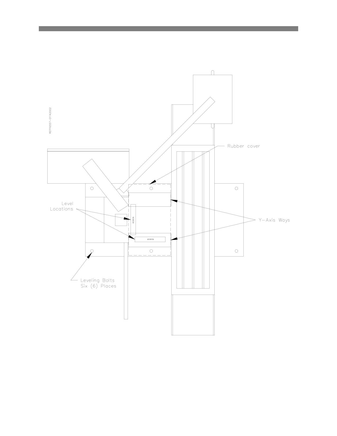
Six Hex head bolts, six jam nuts, and six purple leveling pads are provided with the machine for leveling.
Refer to the following illustrations for leveling bolt locations. Screw the jam nuts all the way onto the
bolts; insert the bolts at the base support points. Screw the bolts in until they are just protruding from the
bottom of the base casting. Lower the machine onto the Leveling pads, making sure the bolts seat into
the recessed area of the leveling pads.
Make sure there is equal pressure on each of the leveling bolts. Remove he protective rubber cover,
located behind the table, from the Y-Axis (In/Out). Place the level on the Y-Axis ways, level the ways in
both directions (Horizontal / In-Out) within .0005”.
Check the level in both directions on the Table. If it does not match the alignment of the Y-Axis ways
refer to the Maintenance Chapter of this manual for full alignment procedures.
Introduction / Safety / Installation
1-6
F65 Manual
Leveling Locations:
Introduction / Safety / Installation
1-7
F65 Manual
Air Supply:
It is very important that the air source for the F65 be moisture free. Water and oil in the air lines will
result in early cylinder and valve failure as well as introducing moisture into the Inner spindle bearings.
The factory recommends installing a water trap at the machine.
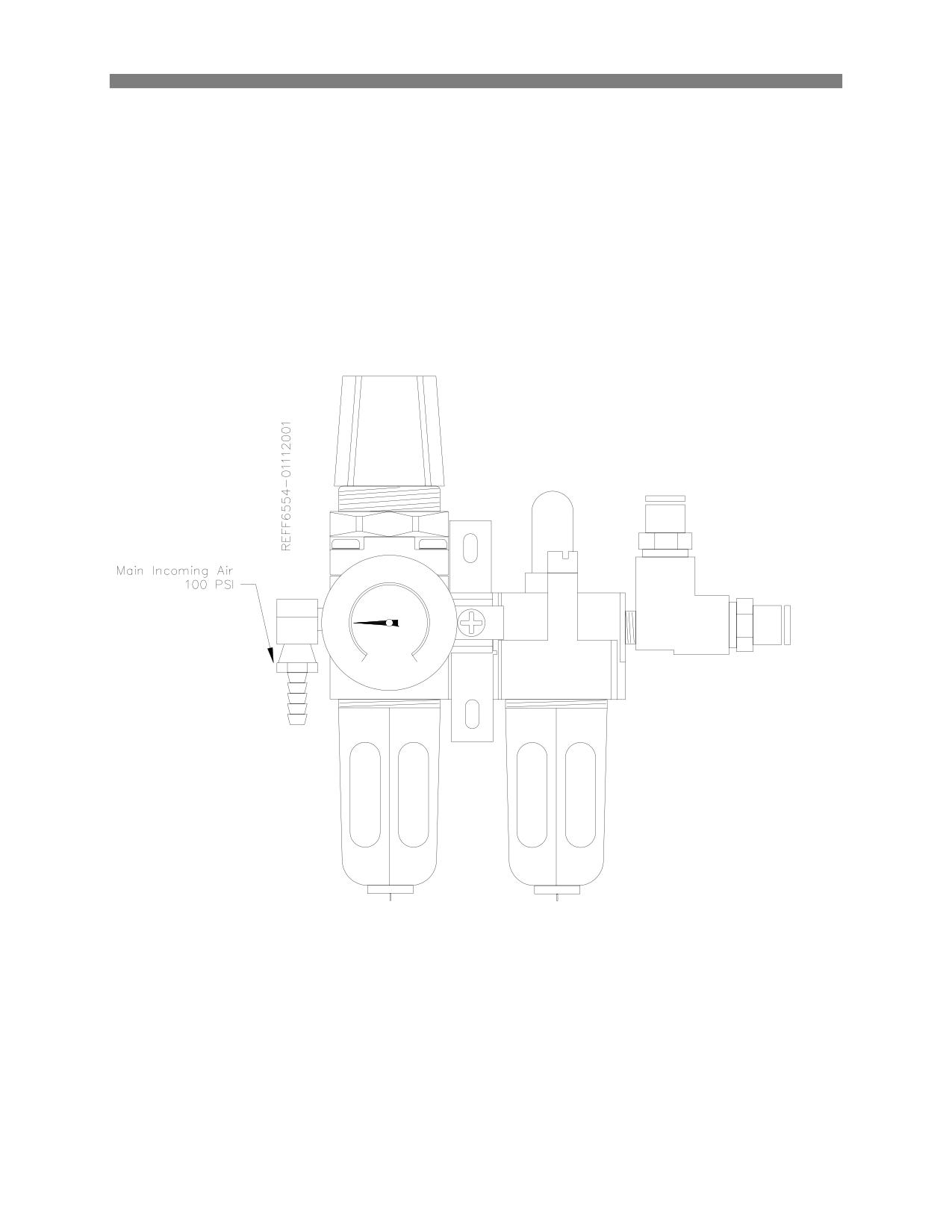
Attach a 100 P.S.I. air source to the main air intake located on the right hand side of the main rear
enclosure.
Introduction / Safety / Installation
1-8
F65 Manual
Power Supply:
This machine has the following power requirements:
208 to 240 VAC
Single Phase
50 or 60 Hertz
30 amps
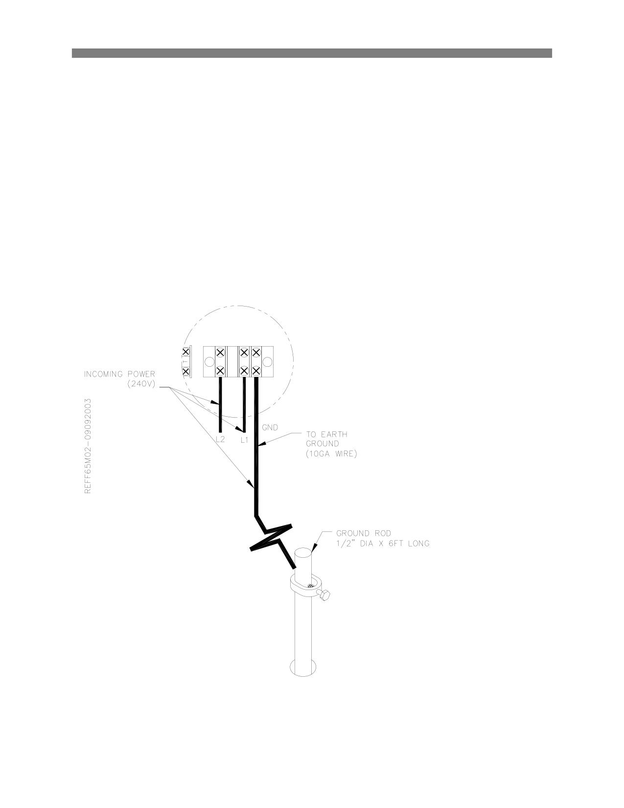
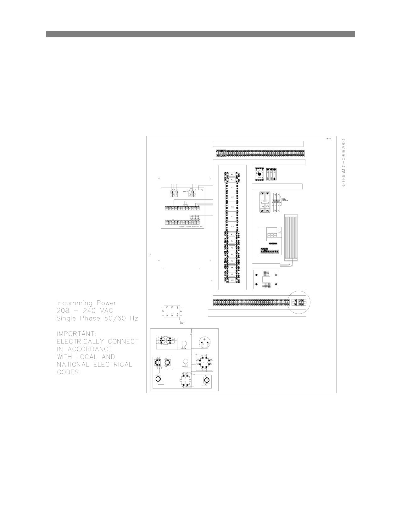
See illustration below for correct connection of “measured” incoming power. Connect single phase wiring
to the main rear enclosure, located on the right rear of machine base. The connection point for power is
located inside the enclosure. The connection termination point is located on the left hand side of the
electrical panel about half way up. Connect L1 to the Grey terminal block, L2 (neutral) to the blue
terminal block and shop ground to the green and yellow terminal block. Attach wire from the grounding
rod to the second green and yellow terminal. Important: Electrically connect in accordance with
national and local electrical codes.
Grounding:
This machine must be connected to a good earth ground rod. A 6 foot, ½” diameter, 15 OHM, Copper
grounding rod driven into the earth next to the machines is preferred. Not providing a grounding rod
could void factory warranty.
Introduction / Safety / Installation
1-9
F65 Manual
Electrical Enclosure:
Introduction / Safety / Installation
1-10
F65 Manual
Getting Started:
Once power has been supplied to the machine measure the incoming voltage with a meter to verify
proper voltages before turning the Main Power switch on. Failure to measure and record proper voltages
to the machine could cause damage and will void factory warranty. Measure L1 to L2 and record on the
installation report. Record L1 to ground and L2 to ground and record on the installation report.
Power Up:
Turn the Main Power switch on.
Shipping Restraints:
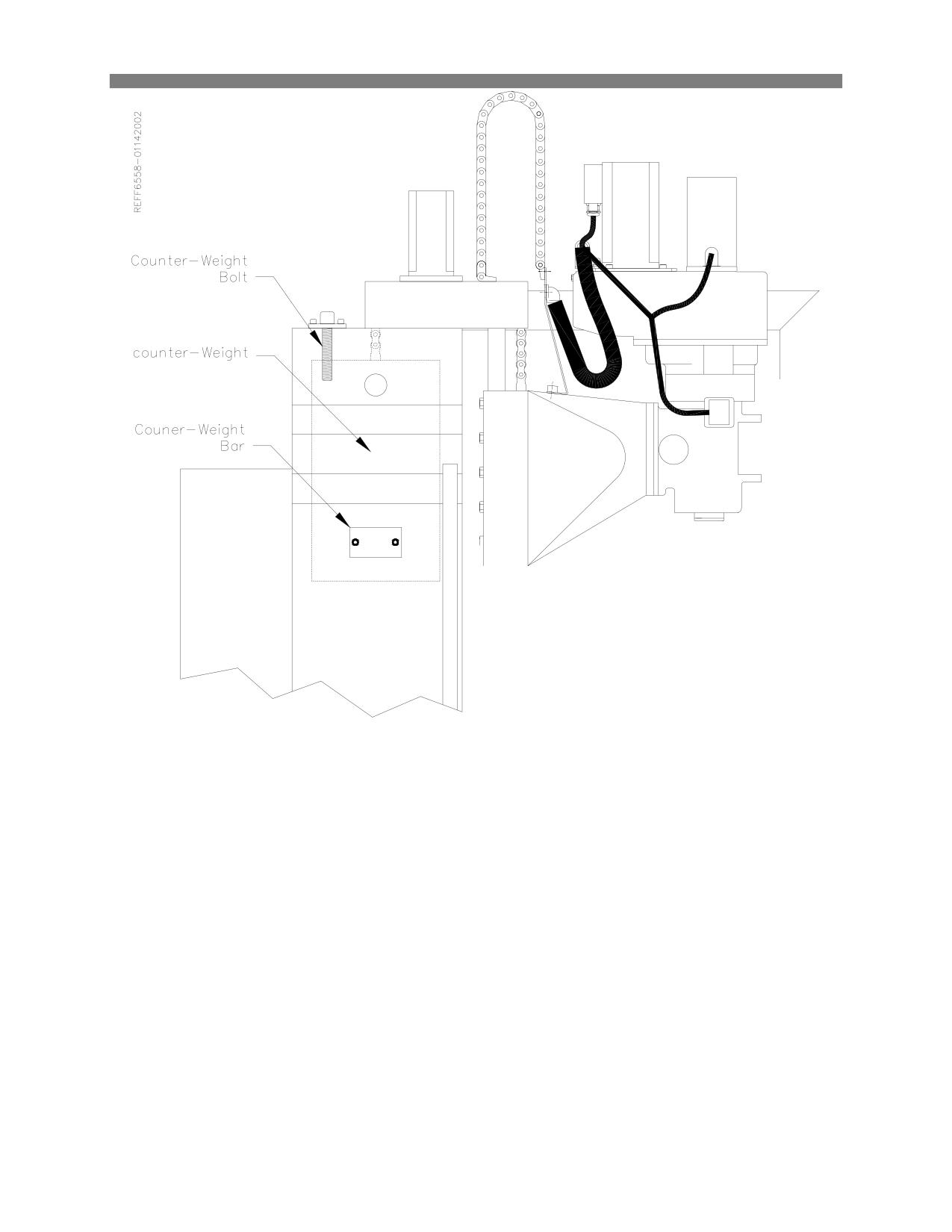
There are three main shipping restraints on the F65. A restraint under the spindle, a bar through the
counter weight and a Bolt in the top of the counter-weight. The following is the procedure for removing
these restraints.
IMPORTANT: Do not ouch any of the rapid travel movements on the machine at this time.
Spindle Support:
Use the vertical manual handwheel to lift the up off of the support.
Counter-Weight Bar and Bolt:
Remove the two bolts securing the Counter-Weight Bar. Using the Vertical handwheel move the Spindle
head up slowly until the Counter-Weight bar is free. Remove the bar and save for possible later use in
shipping. Loosen the Counter-Weight bolt until it is free from the Counter-Weight. Once it is free, it can
remain in the bracket. The Rapid travel buttons can now be used on the machine.
Introduction / Safety / Installation
1-11
F65 Manual
It is important that the operator of the F65 read the Control Definitions chapter in this manual before
proceeding any further.

Control Definitions
2-1
F65 Manual
Chapter 2 Control Definitions:
The purpose of this chapter is to define the function of the buttons throughout the various screens.
Certain button functions may not make sense right away in this chapter. As the operator reads through
the Operating Instructions chapter of this manual, the function of these buttons will become clear.
Master Power On/Off Switch:
This switch is located on the main electrical control enclosure on the right hand side of the machine. The
switch must be in the off position before opening the rear enclosure door.
Power Air Draw Bar Switch:
This switch is located just to the left of the spindle mounted on the spindle housing. It has a In and Out
button along with a safety button. The safety button on the left-hand side of the switch must be held in to
operate the In or Out buttons.
This switch will spin the draw bar Forward or Reverse to install or remove the tool holder.
All tool holders on the F65 are standard 40 taper and can be purchase through your local tooling vendor.
Operating Instructions
3-1
F65 Manual
Chapter 3 Operating Instructions:
The purpose of this chapter is to explain and then guide the operator from loading blocks to running an
automatic cycle.
All modes of operation will be discussed in this chapter.
Loading a Block:
Performance Fixture 650-3-1 Boring:
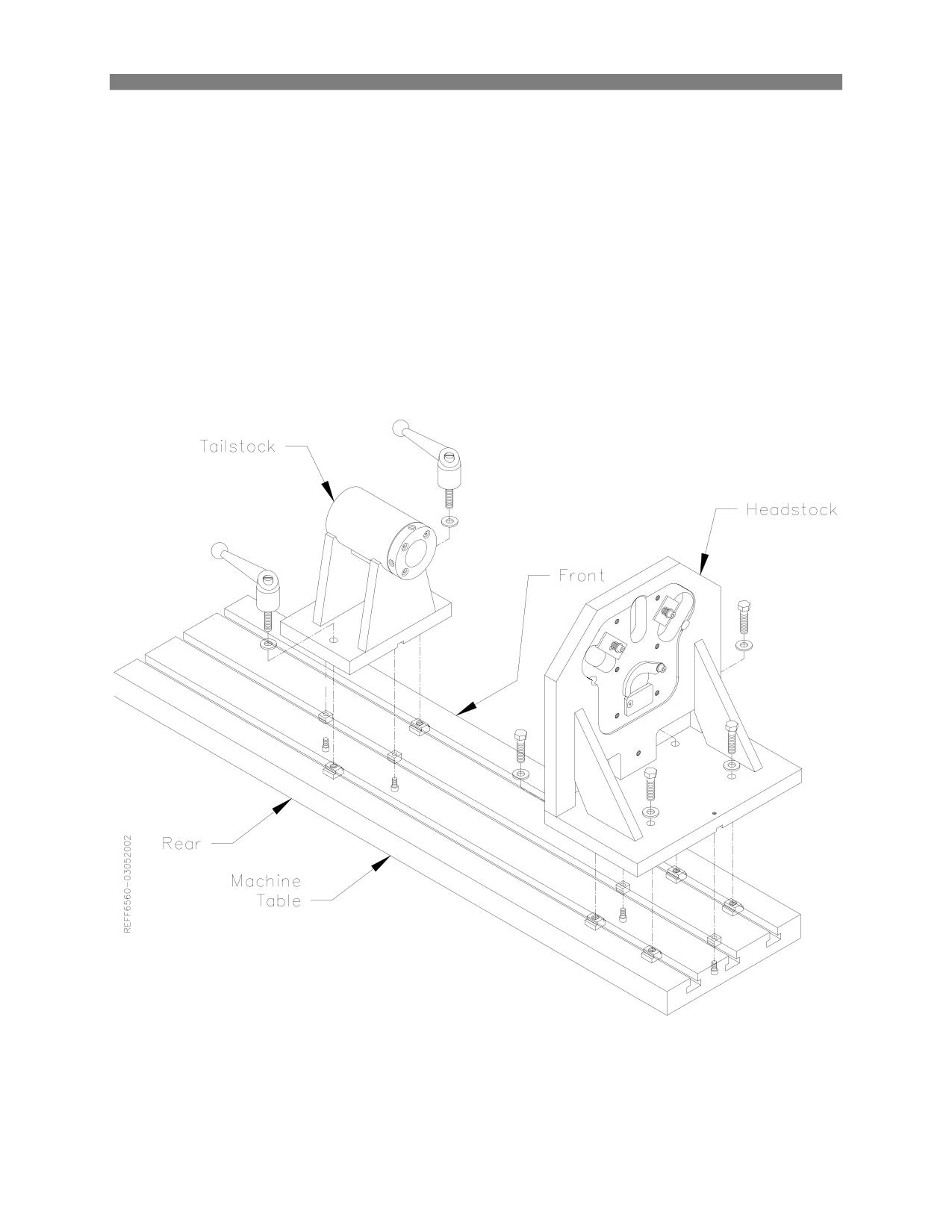
1) Install and align the performance fixture head stock on the left hand side of the table as shown
below. Follow the alignment procedures for the Performance fixture in the Maintenance section of
this manual. Tighten the Head Stock to the table securely using the four Hex bolts and T-Nuts.
2) Install the Tail Stock onto the right hand side of the table but do not tighten down.
Operating Instructions
3-2
F65 Manual
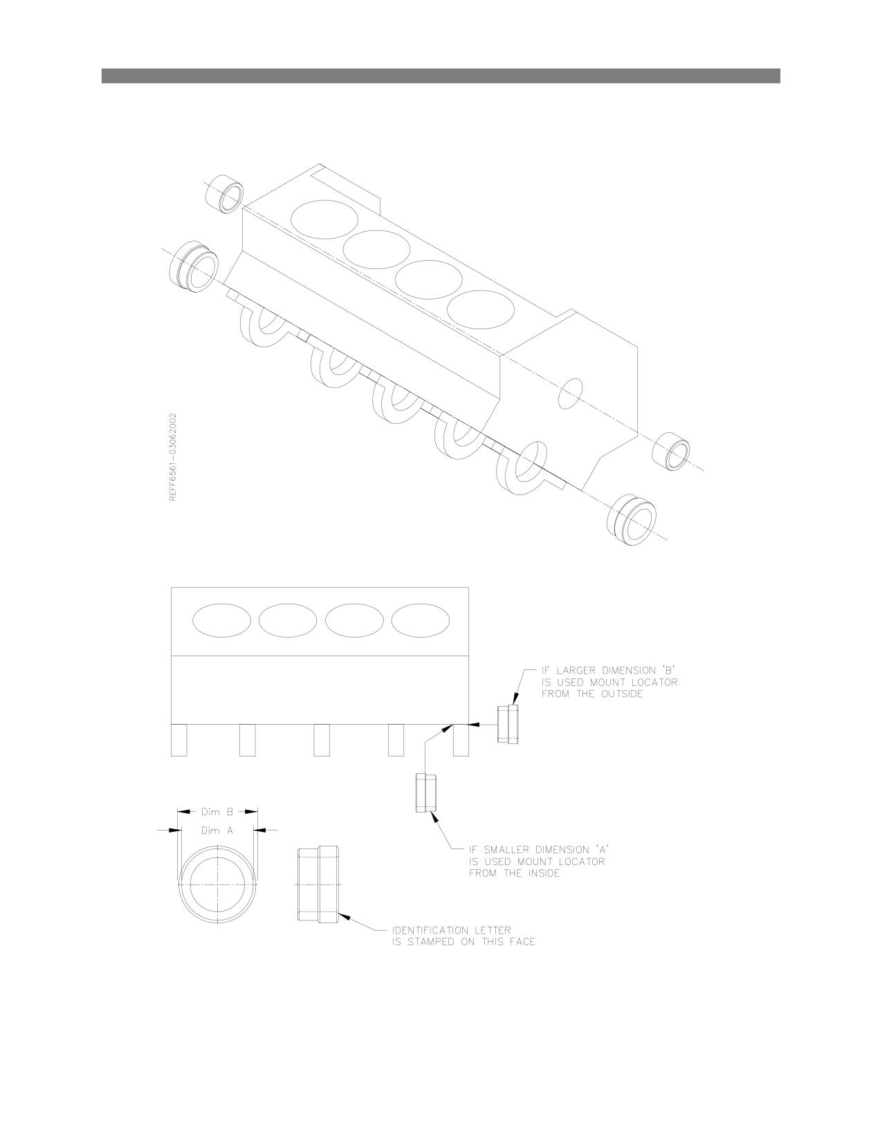
3) Select the correct Main and Cam bushing for the block you are going to be using from the tables in
the Options section of this manual. Place bushings in block as shown below.
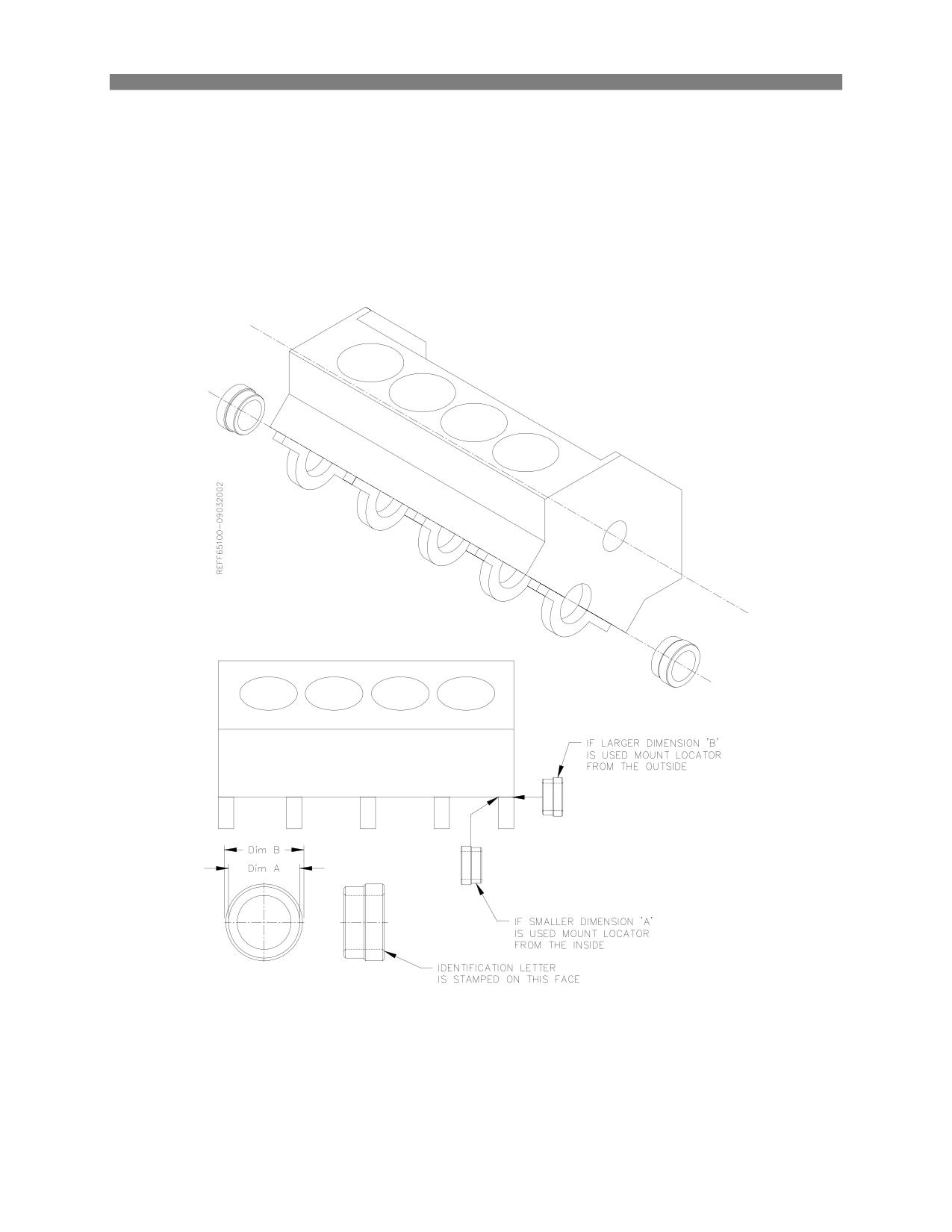
Note: Each locator covers two bearing diameters (‘A’ and ‘B’). The unused diameter MUST be
placed INSIDE the block to prevent interference with the Index plates.
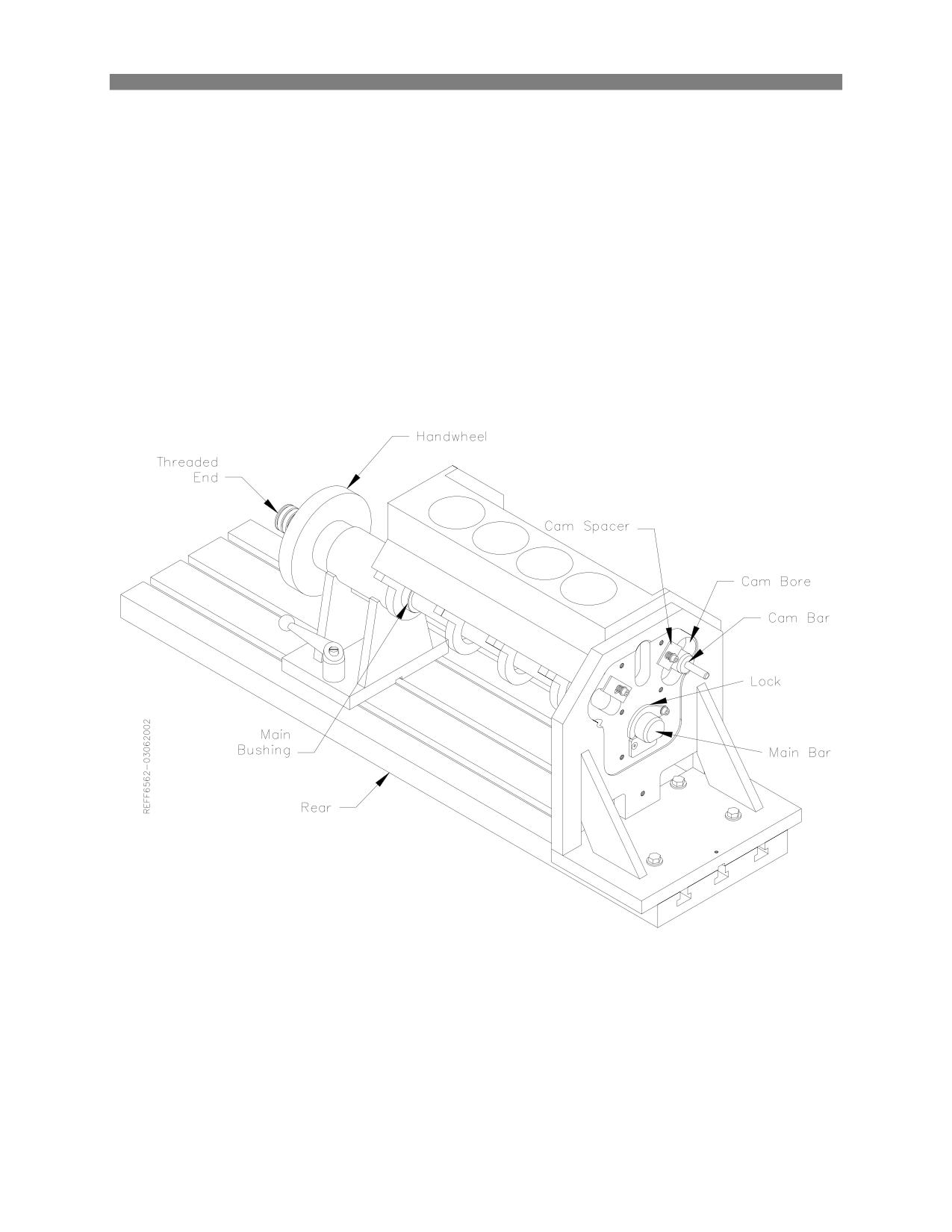
Operating Instructions
3-3
F65 Manual
4) Using a slow travel hoist, position the block between the Head stock and Tail stock with the Bell
housing end of the block towards the Head stock.
5) Slide the unthreaded end of the Main Bar through the Tail stock, both Main bushings and into the
Head stock with the flat facing down. The threaded end of the Main Bar should be on the Tail stock
side of the table. Slide the Lock into the groove on the Main Bar.
6) Rotate the block until the bank you want to bore is facing up. Make sure the cam spacer is not in the
cam Bore area at this time. Slide the Cam Bar through the two Cam bushings and into the Head
stock with the reduced diameter at the Head stock.
7) Snap the Cam spacer into place.
8) Push the Tail stock up to the block. Tighten the Handwheel with a quick snapping motion.
9) Tighten the two handles on the Tail stock.
The block and fixture are now locked in place and ready for machining.
Operating Instructions
3-4
F65 Manual
Performance Fixture 650-3-1 Lifter Boring:
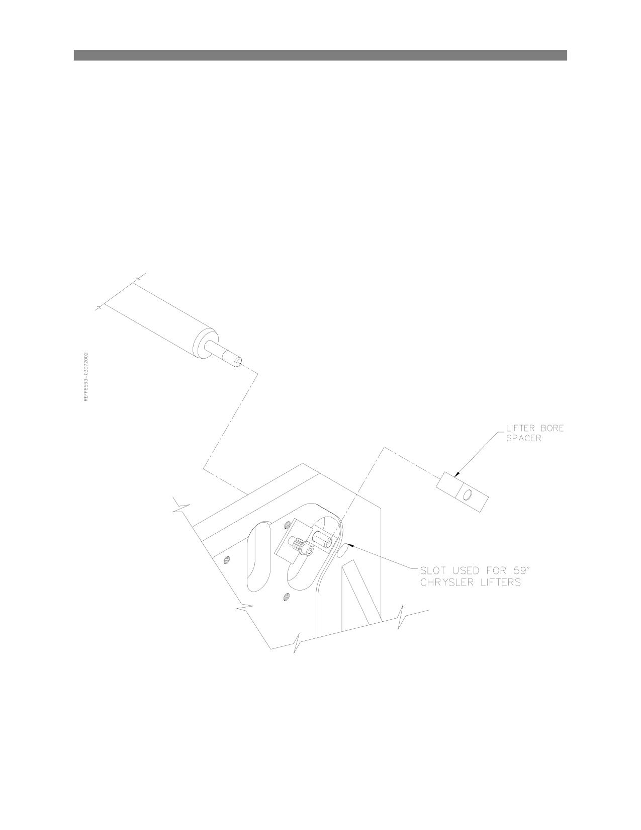
The same procedure for loading a block in Lifter boring as was used in Boring with an exception in the
Cam Bar area.
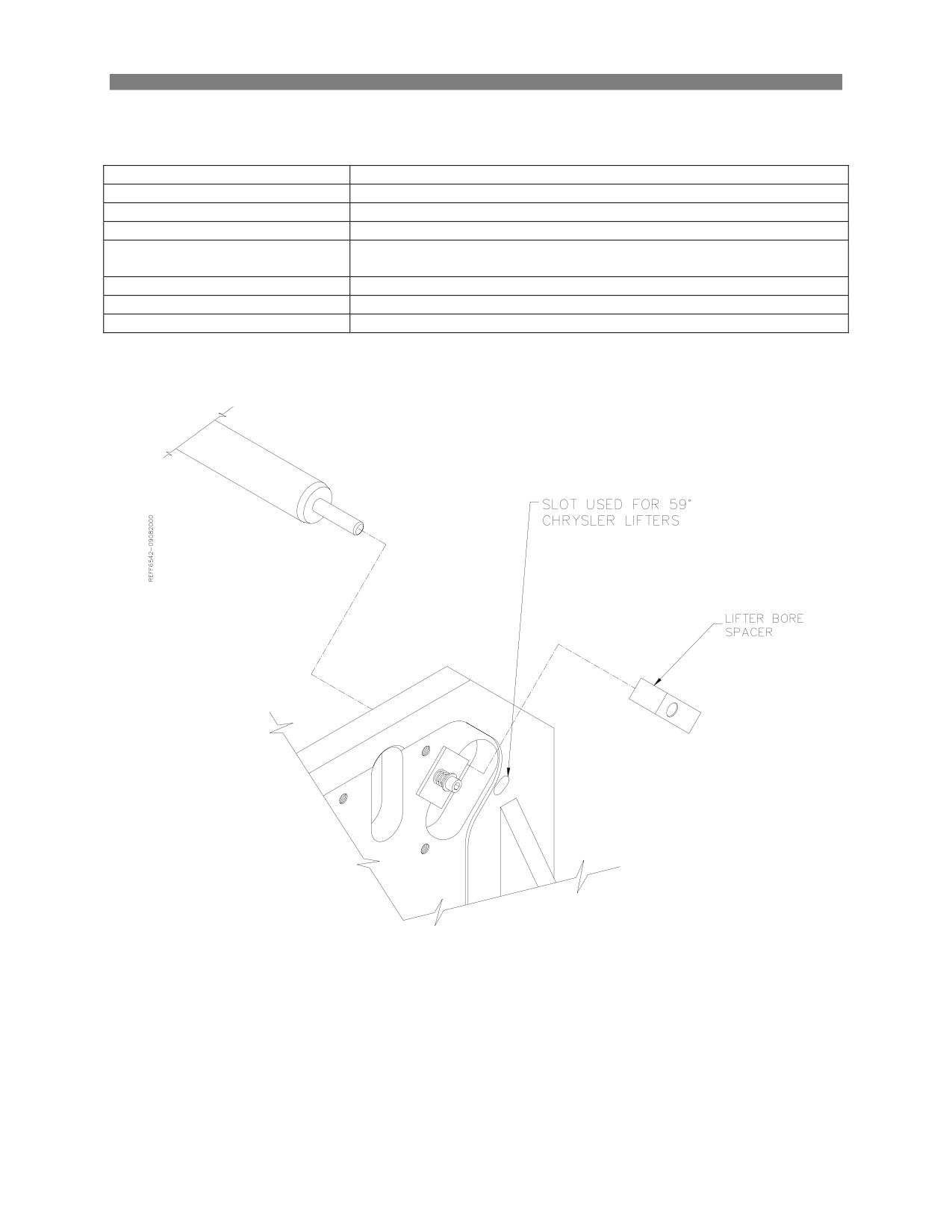
1) Instead of the Cam Bar being slid through the Cam Bore to its full Diameter, the small shaft on the
end of the Cam Bar is used in conjunction with spacer Blocks.
2) Select the correct Spacer from the Chart in the Options section of this manual for the angle of the
Lifter Bores.
3) The Cam Spacer must be out of the Cam Bore.
4) See illustration below for spacer installation.
Operating Instructions
3-5
F65 Manual
Lower End Machining Package 650-3-1A:
1) Install and align the performance fixture head stock on the left hand side of the table as shown in the
Performance Fixture section. Follow the alignment procedures for the Performance fixture in the
Maintenance section of this manual. Tighten the Head Stock to the table securely using the four Hex
bolts and T-Nuts.
2) Install the Tail Stock onto the right hand side of the table but do not tighten down.
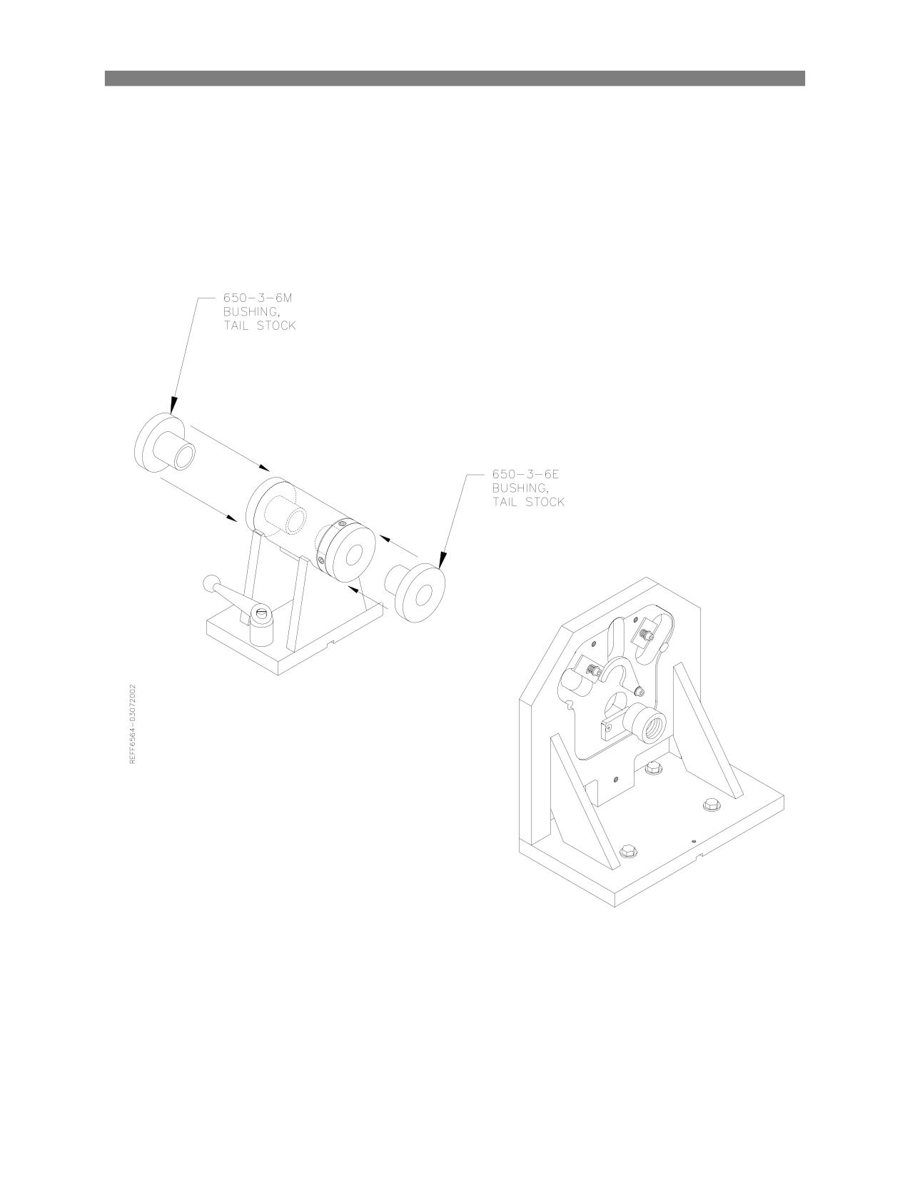
3) Install the Tail stock bushings 650-3-6E and 650-3-6M into the Tail stock as shown below.
Operating Instructions
3-6
F65 Manual
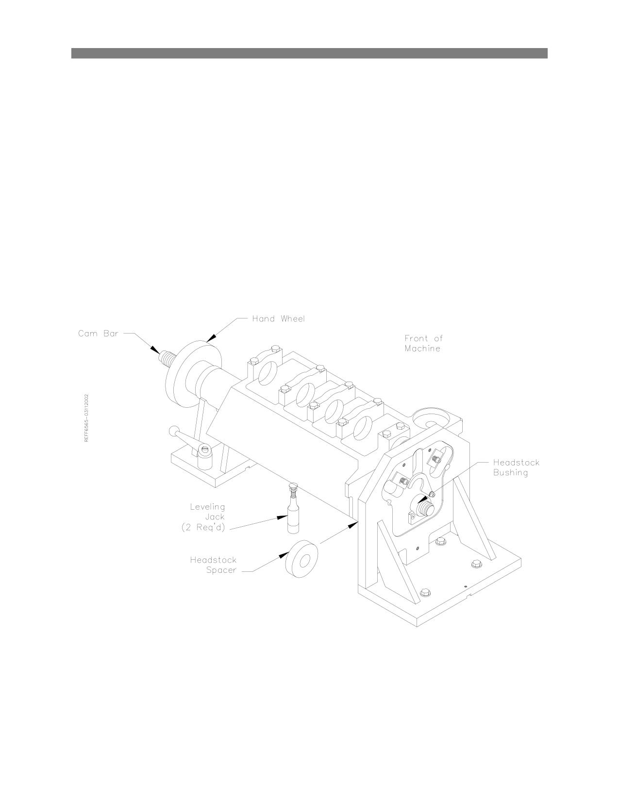
4) Select the correct size Cam Bushings for the block you are using and install them into the block.
5) Using a slow travel hoist, position the block between the Head stock and Tail stock with the Bell
housing end of the block towards the Head stock with the Main Caps facing up.
6) Install Head stock bushing into Head stock with the flat facing down and the smaller diameter into the
Main bore of the Head stock.
7) Slide the Cam Bar (short threaded end first) through the Tail stock bushings, Cam bushings (installed
in block) and Head stock Spacer.
8) Thread the Cam Bar into the Head stock Bushing until tight.
9) Slide the Tail stock up to the block.
10) Snug the handwheel up to the Tail stock but do not lock in place.
11) Install the Leveling Jacks between the underside of the block and the bed of the machine. One each
side.
12) Rotate the block until the Pan Rails are even to each other.
13) Make sure there is even pressure on each of the Leveling Jacks.
14) Tighten the Handwheel into place.
15) Tighten the Tail stock into place using the handles.
The block and fixture are now locked in place and ready for machining.
Operating Instructions
3-7
F65 Manual
Block End Truing Fixture 650-3-30:
If you are truing the ends of a block use the standard Head stock mentioned in the Maintenance section
of this manual.
If you are Boring the Cam Tunnels with this fixture follow the standard Head stock in the Maintenance
section of this manual plus the procedure below:
1) Do not have the Head stock hold down bolts all the way tight, the fixture may need to be moved
slightly.
2) The center of the Key Way on the Head stock need to be lined up with the center of the middle Key
Way on the machine bed. This will place the center of the Main bore directly inline with the center of
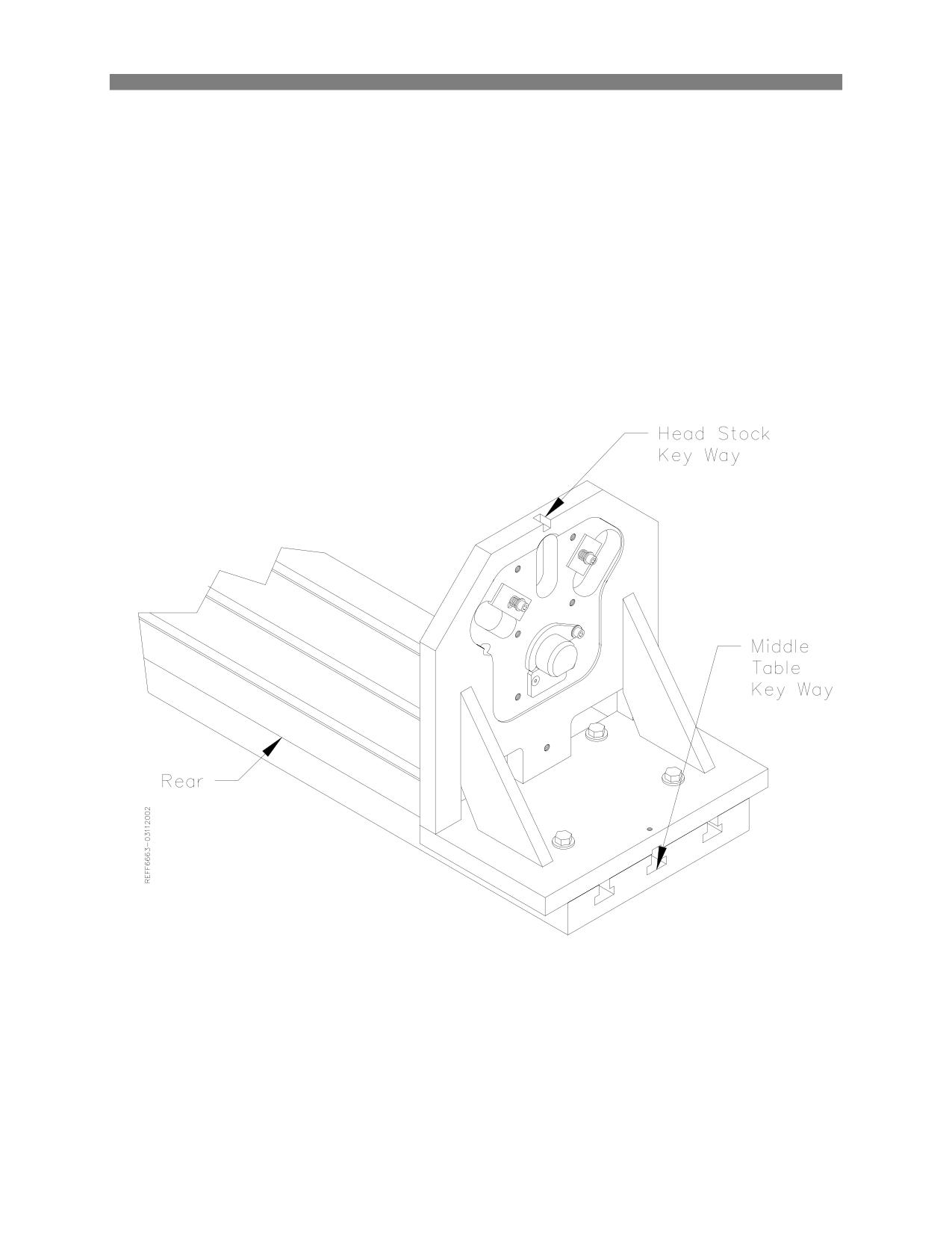
the Cam bore.
3) Lock the Head stock in place.
Operating Instructions
3-8
F65 Manual
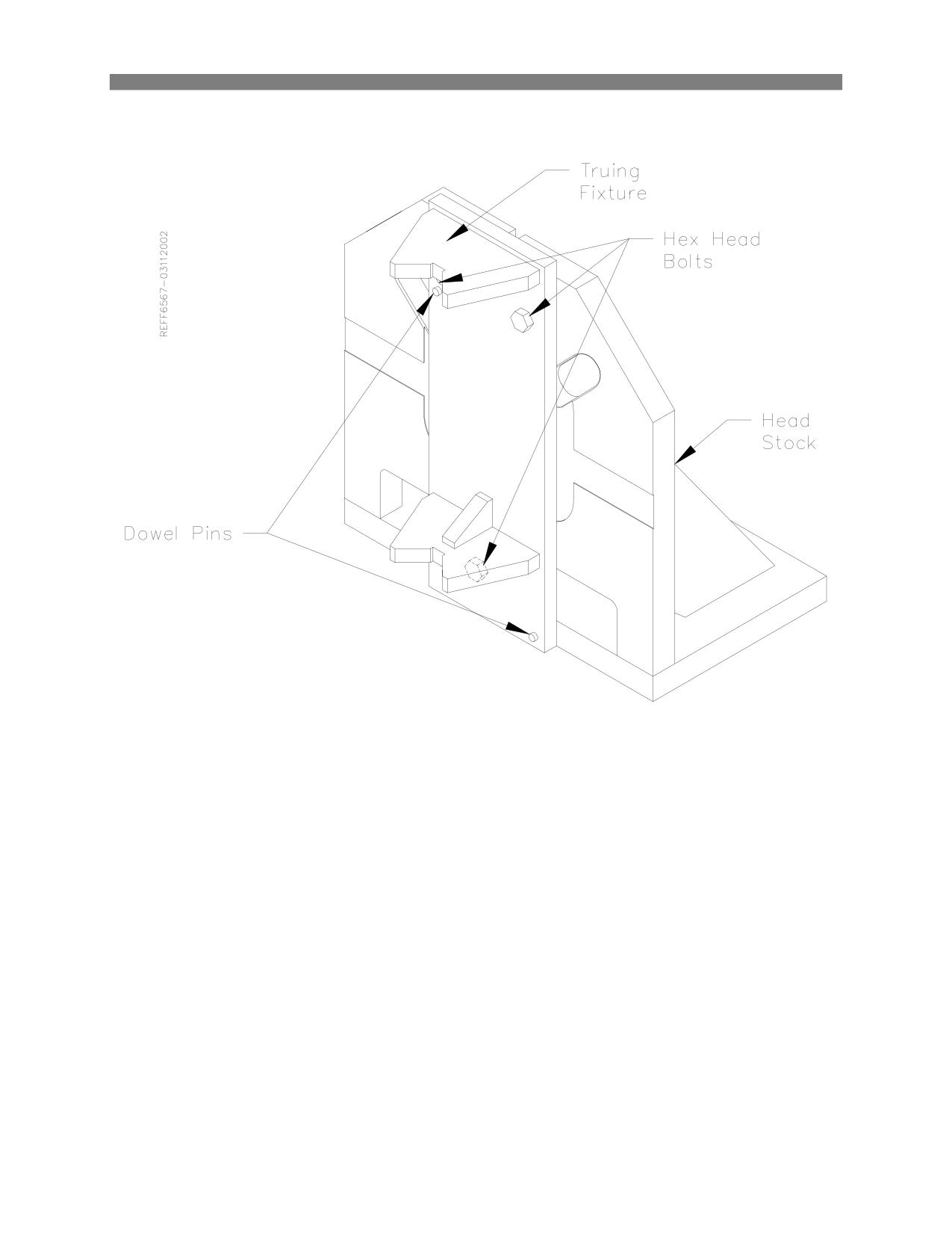
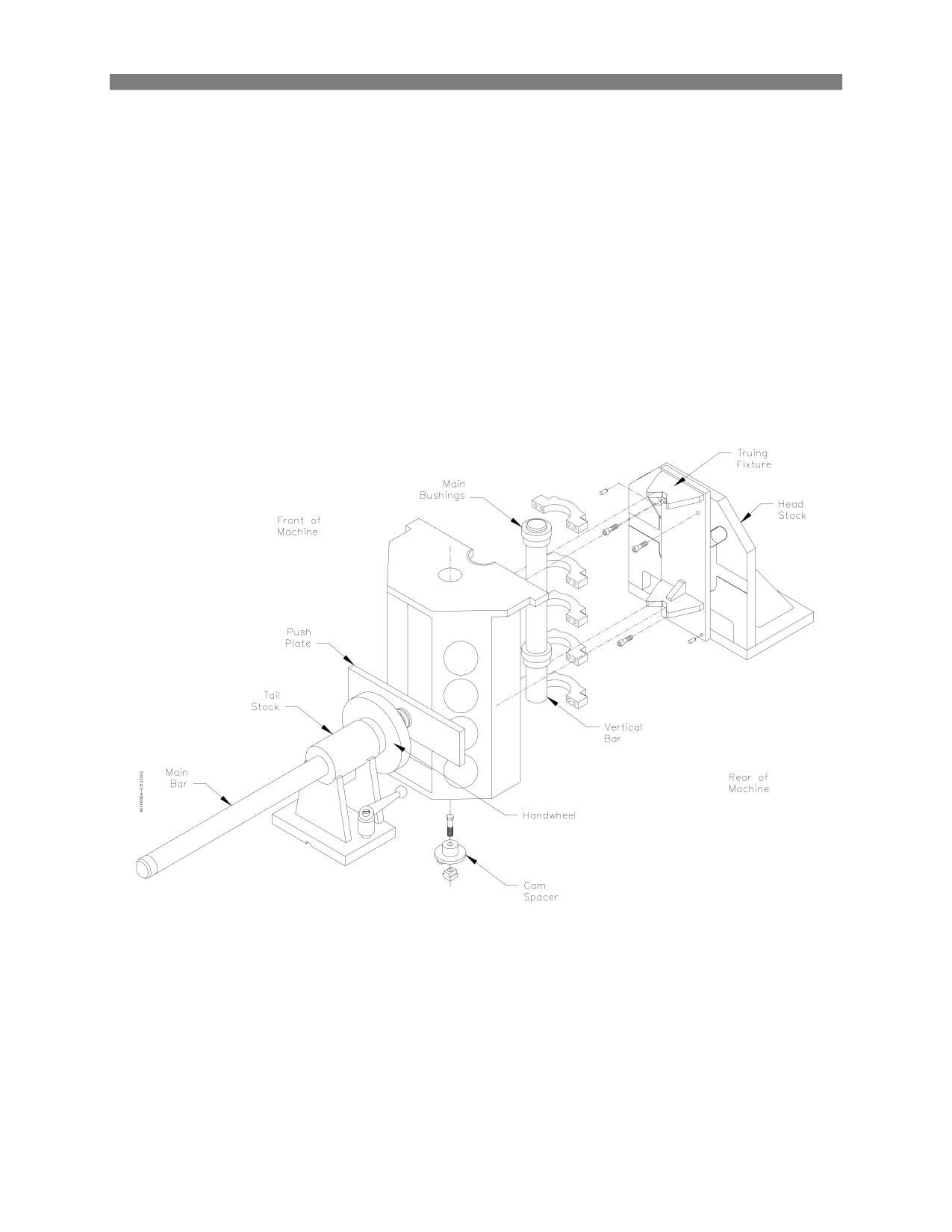
4) Install the Truing Fixture onto the Head stock. Slide the two Dowel pins on the Truing Fixture into the
appropriate Dowel holes on the Head stock.
5) Bolt the Truing Fixture to the Head stock using the three supplied Hex Head Bolts.
The following steps are designed to check the Vertical Bar for straightness. This Bar was checked and
tested at Rottler Manufacturing. The following steps are to make sure there is not a burr or debris
between any of the parts.
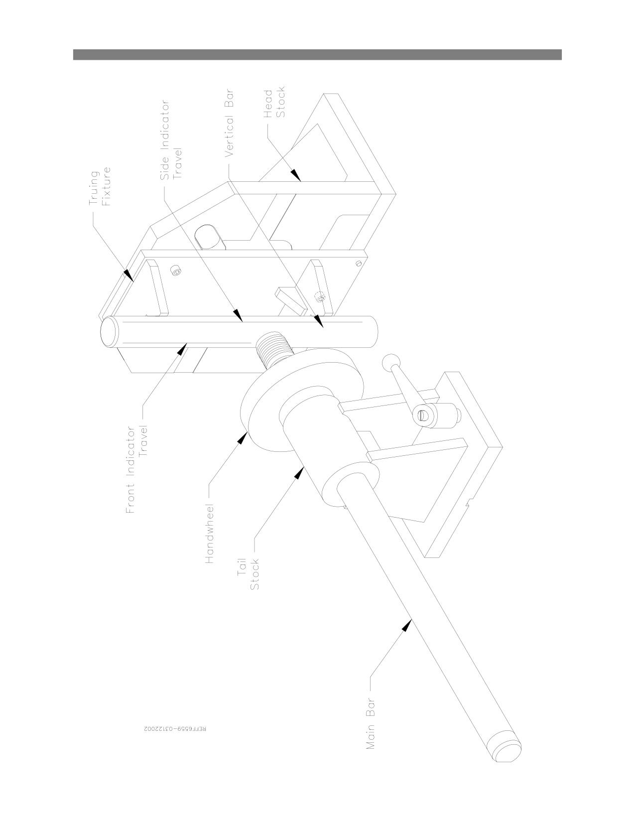
6) Slide the Main Bar though the Tail stock (threaded end first).
7) Thread the Handwheel onto the Main Bar.
8) Place the Vertical Bar into the “V” on the Truing Fixture.
9) Slide the Tail stock towards the Head stock until the Main Bar just touches the vertical Bar.
10) Tighten the Tail stock down.
11) Turn the Handwheel until the Main Bar holds the Vertical Bar securely in place.
12) Attach a indicator to the machine spindle or cutterhead and run it up and down the front and side face
of the Vertical Bar. It should be within .0015 variance.
Note: Front face will only have half travel as the Main Bar obstruct full travel..
Operating Instructions
3-9
F65 Manual
Operating Instructions
3-10
F65 Manual
13) Loosen the Handwheel and remove the Vertical Bar.
14) Loosen the Tail stock and slide it to the right hand side of the machine table.
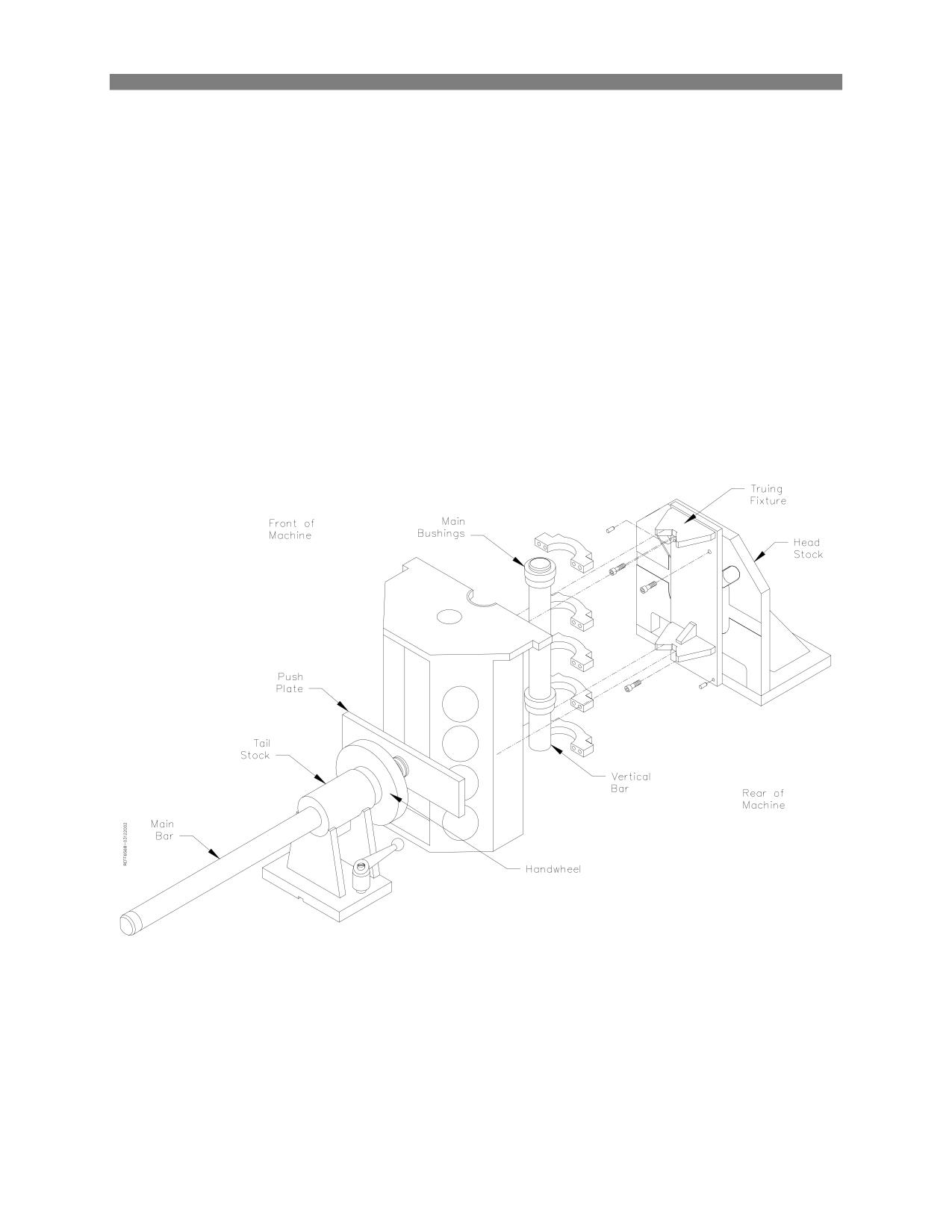
15) Select the correct Main Bushing for the block you are machining from the table in the Options section
of this manual. Install the Main bushings as shown in the Performance Fixture earlier in this section.
16) Using a slow travel hoist position the block between the Head stock and tail stock with the Main Caps
facing the Head stock as shown.
17) Slide the Vertical Bar into the Main bushings from the top. You will want to put a spacer on the table
below the Vertical Bar so the bar does not go below the top V on the Truing fixture
18) Slide the towards the Head stock so that the Main Vertical Bar come to rest in the Vs on the truing
fixture.
19) Slide the Tail stock up to the block and insert push plate as shown.
20) Tighten down the Tail stock.
21) Turn the Handwheel until the push plate has enough tension on it to keep the block from moving.
The block and fixture are now locked in place and ready for machining.
Operating Instructions
3-11
F65 Manual
Block End Truing Fixture 650-3-30 when used with Cam Boring:
When using the End truing Fixture for Cam Boring you will also need tooling package 650-3-43A
1) Use the same set up and line up procedure as with the standard End Truing Fixture discussed earlier
in this section.
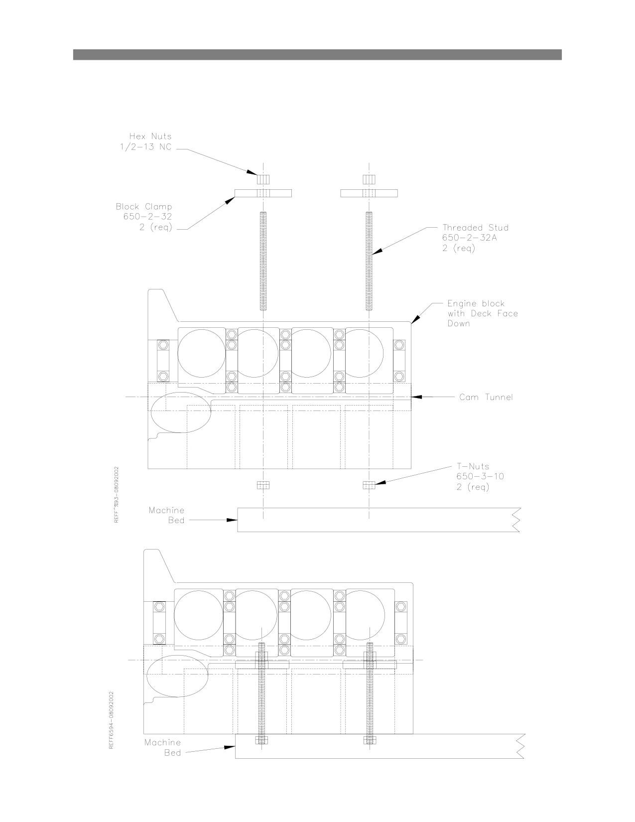
2) Place the Cam Spacer in the middle T-slot of the machine bed along with T-Nut and Bolt.
3) Select the correct Cam Bushing for the block you are going to be machining from the table in the
Option section of this manual.
4) Place the Cam Bushing over the Cam Spacer. This will put the Cam and Main in-line and on center
with the Fixturing.
The block and fixture are now locked in place and ready for machining.
Operating Instructions
3-12
F65 Manual
Cam Tunnel Boring:
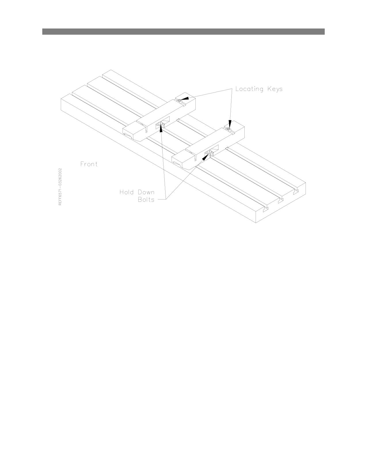
1) Place two T-Nuts in the outside keyway (closest to operator).
2) Mount block onto machine bed, as shown below with the right most cylinder hanging off the machine
bed.
3) Place threaded rod through the first and third bores and thread into T-Nuts.
Operating Instructions
3-13
F65 Manual
4) Screw the supplied ½-13 NC nuts on to the threaded rod and snug them up. Do not tighten tehm all
the way at this point.
5) Attach a magnetic base indicator to the spindle and run it along the upper pan rail to get it relatively
straight. It does not need to be perfectly strait because a double flex coupling is used.
6) Tighten the ½-13 nuts down.
The block and fixture are now locked in place and ready for machining.
Operating Instructions
3-14
F65 Manual
V6/V8 Manual Fixture Assembly 502-1-72H:
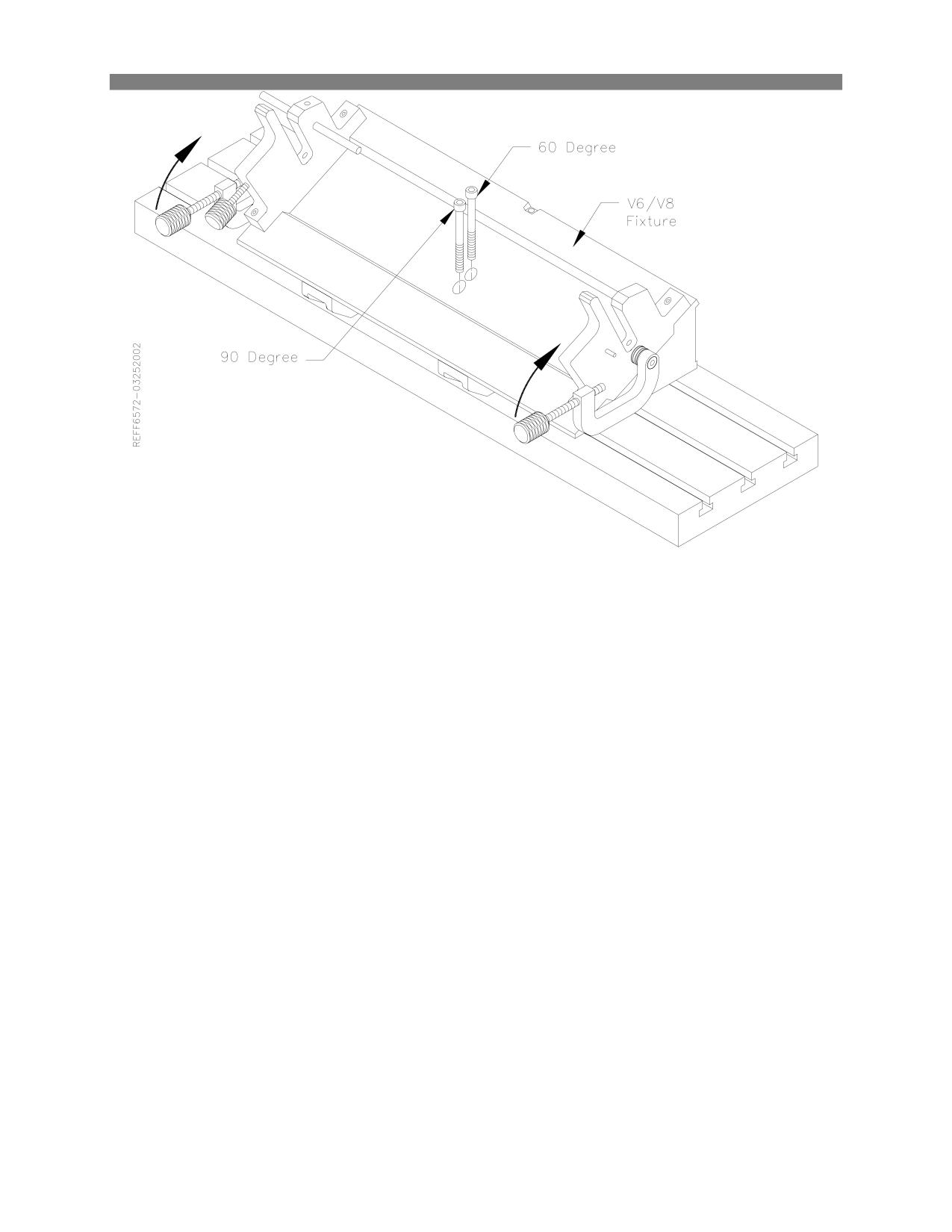
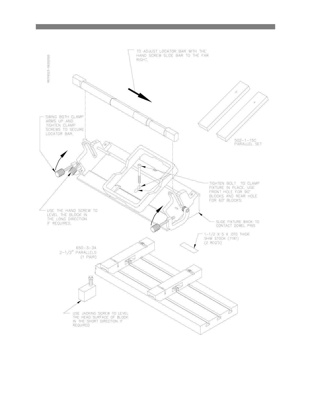
1) Place parallels 650-3-34 on Machine bed 10 inches apart and secure with T-Nut and Hex bolts that
are provided. The keys on the bottom of the parallels go in the back Key Way.
2) Select the 60 or 90 degree position for the fixture. Using a slow moving hoist, set the V6/V8 fixture
onto the parallels.
3) Push the V6/V8 fixture back on the parallels until the keys in the top of the parallels line up to the
machined sections on the rear of the V6/V8 fixture.
4) Use the supplied Socket Head cap Screw and T-Nut to secure the fixture in place.
Operating Instructions
3-15
F65 Manual
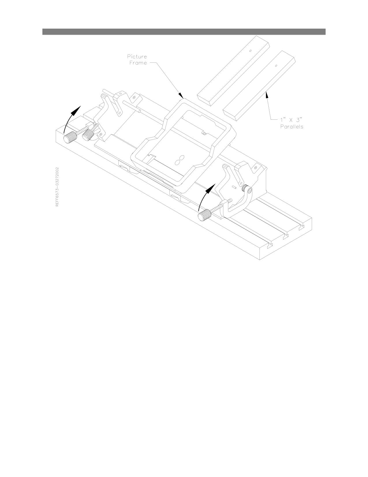
5) Decide if the Picture Frame or the 1” X 3” will need to be used.
Operating Instructions
3-16
F65 Manual
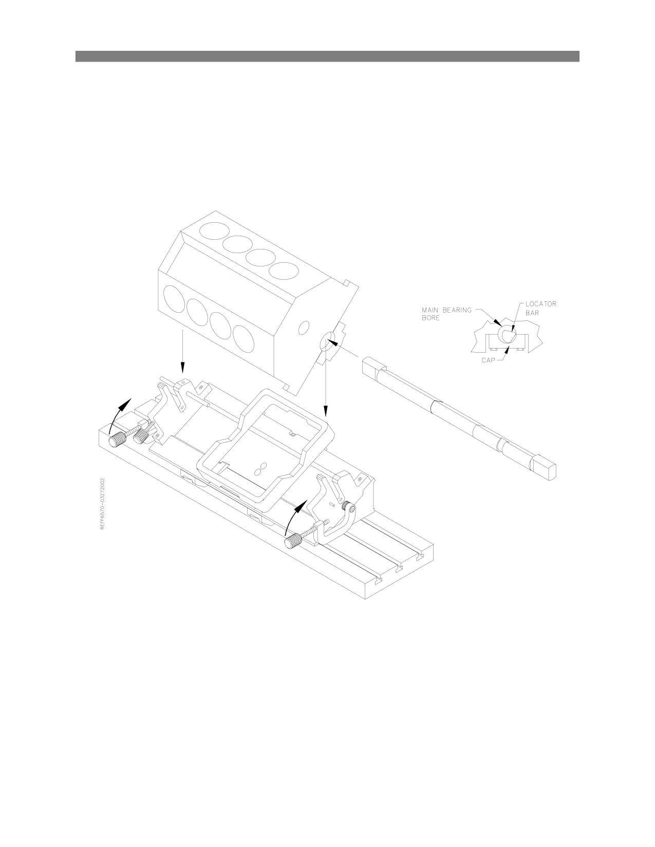
6) Slide the Locator Bar through the Mains of the block.
7) Lower the block with the Locator Bar installed into the V6/V8 fixture. Clamp the Locator Bar with the
screw in clamps. Shown on next page.
For a more detailed description on properly using and adjusting the V6/V8 fixture refer to the Manual
V6/V8 Combination Fixture 502-1-72H in the Options section of this manual.
Operating Instructions
3-17
F65 Manual
Maintenance
4-1
F65 Manual
Chapter 4 Maintenance:
Lubrication
Manual Lubrication
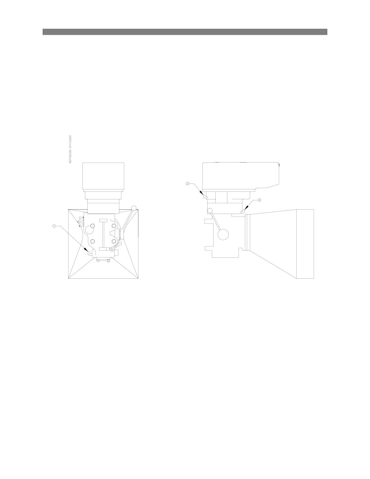
Lubricate, in the places indicated, weekly with 5-6 drops of Union 76 Way Oil HD-68 or equivalent
lubricant.
Automatic Lubrication System
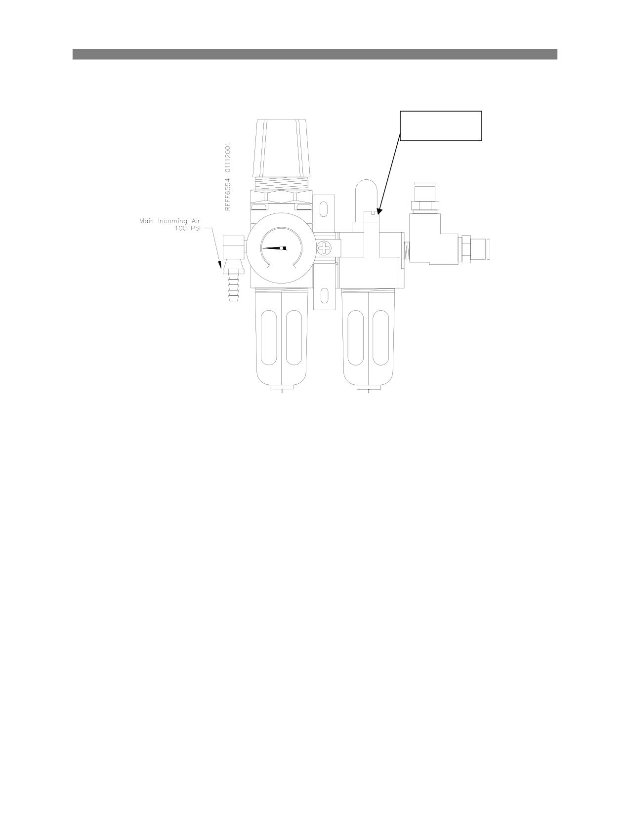
The automatic lubrication system includes metering valves for proportional distribution and includes an
alarm for low fluid level warning. Still, please check fluid level before operation. Add Union 76 Way Oil
HD-68, or equivalent, as needed in reservoir at rear of machine.
Maintenance
4-2
F65 Manual
Power Draw Bar Lubrication:
The Power Draw Bar assembly needs to have oil supplied in the air line to it. Use machine tool oil in this
reservoir. The reservoir is located on the back of the main column of the machine. Refer to the following
illustration for filling location.
Remove
screw to fill
Maintenance
4-3
F65 Manual
Leveling and Alignment:
The following is a description of how to properly level and align the F65 machine. These procedures
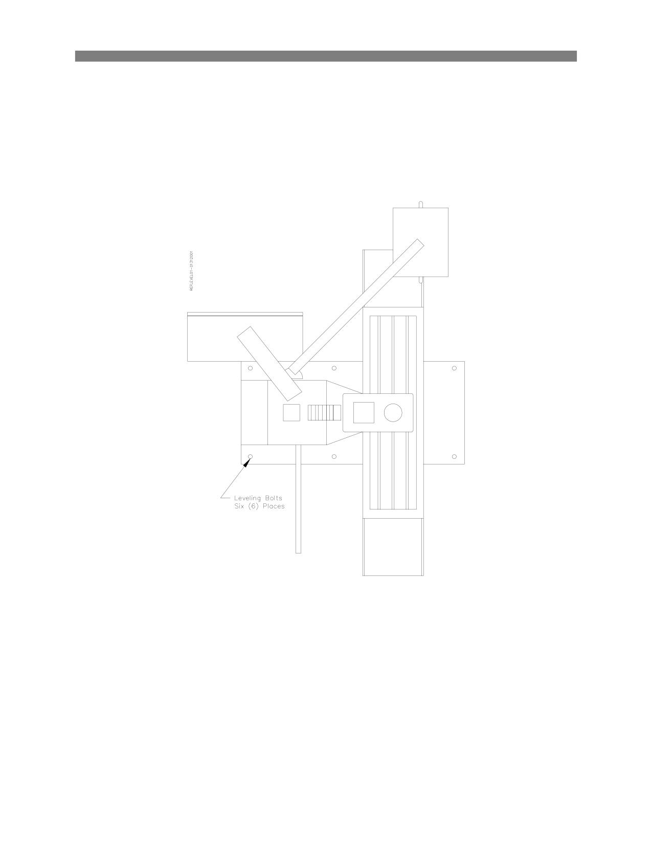
should be followed in the order they written to obtain correct machine level and alignment.
Leveling the Machine:
After uncrating the F65 set it down in desired location with leveling bolts and leveling pads installed.
Remove the Y-Axis protective rubber located on the backside of the table. This is where you will position
the level to level the machine. A .0005” increment per foot precision level is required.
Using the four (4) corner leveling bolt to start with, bring the machine up to level in both directions (front to
back and left to right) within .0005” per foot.
After you have leveled the bed using the four corner bolts, move to the middle leveling bolts. Bring these
bolts down until they have approximately the same amount of pressure on them as them as the four
corner bolts. Be careful not to throw the level of the machine off while doing this.
This will put the lower casting level.
Maintenance
4-4
F65 Manual
Alignment:
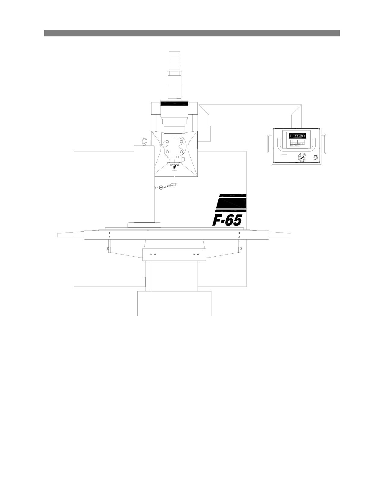
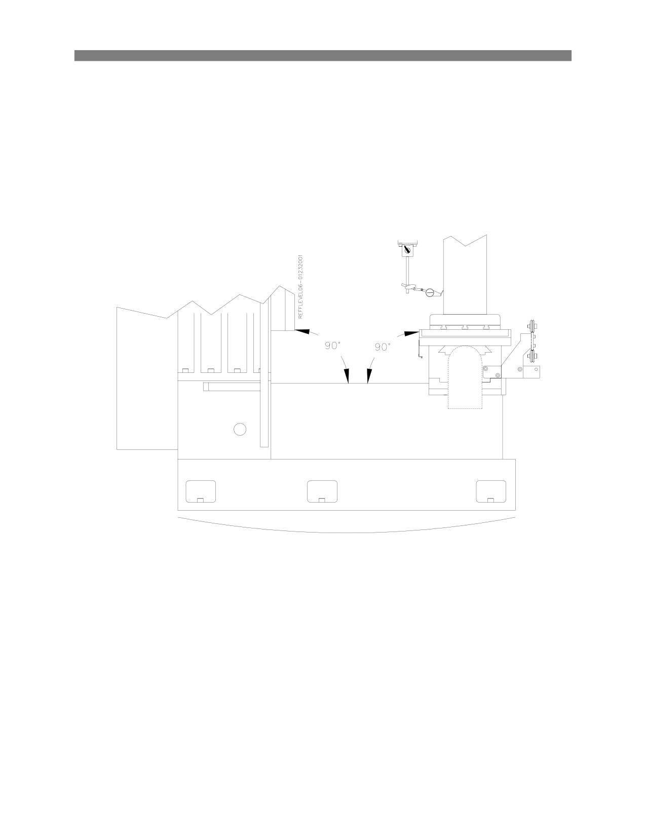
Place the alignment cylinder on the table in roughly the same position as shown on the following page.
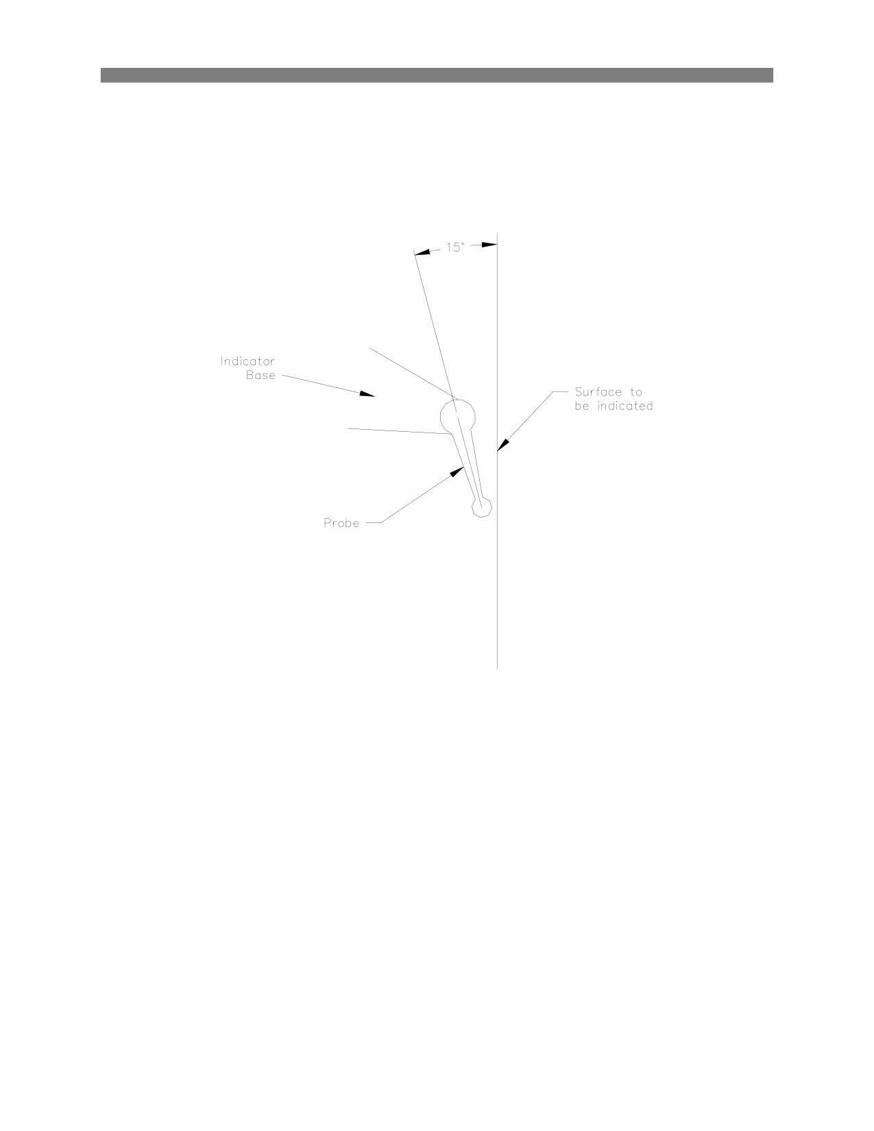
Note: The position (angle) of the probe to the surface you are indicating is critical. Using an
incorrect angle on the probe will result in inaccurate readings from the surface being indicated.
The angle of the probe should be at about 15 degrees from the surface being indicated (see
illustration 2).
Maintenance
4-5
F65 Manual
SAFETY CHECK
WARNING:
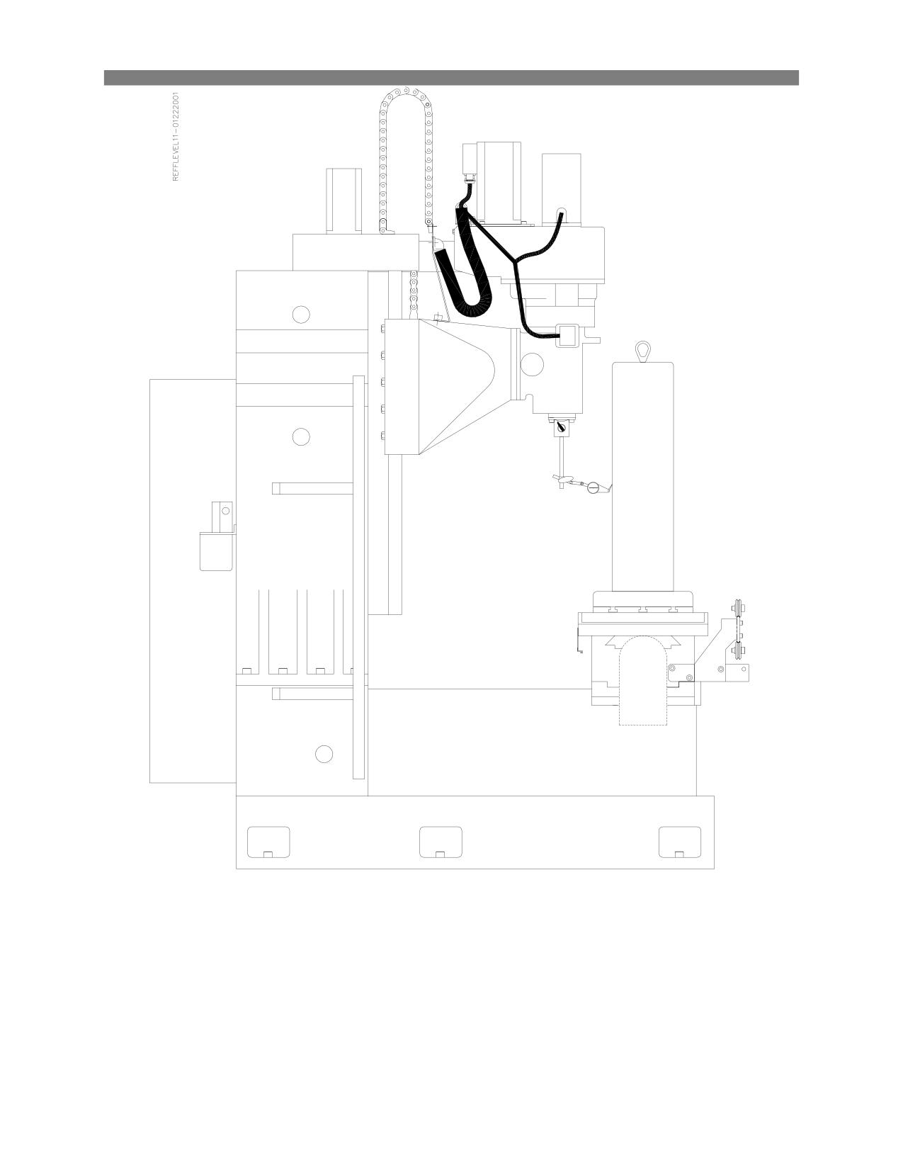
Put about .010” pressure on the indicator. Run the vertical throughout its full travel. The runout should
not be more than .0005. If the runout is more than this, check the table top as well as the bottom of the
alignment cylinder for burrs or debris.
Move the table out and check the perpendicularity of the vertical ways. This should be within .0005”.
Maintenance
4-6
F65 Manual
If the Vertical perpendicularity is not within tolerance the Middle Leveling Bolts may need to be adjusted.
Maintenance
4-7
F65 Manual
Middle Leveling Bolts:
If the procedures for the Leveling was followed correctly, it is unlikely that the deviance from Front to Back
is being caused by the Middle Leveling Bolts. The following are examples of what could be caused by
incorrect pressure on the middle leveling bolts.
Example 1: Zero the indicator on the top of the cylinder. When traveling to the bottom of the cylinder, if
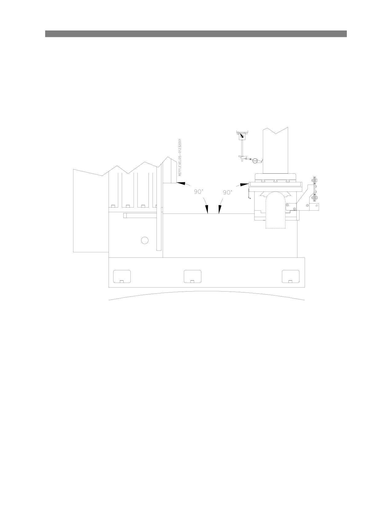
the reading decreases past -.001” to something such as -.002”, then the middle leveling bolts have too
little pressure on them and it is bowing the casting slightly in the middle as shown below.
The arched line underneath the picture is illustrating the bow to the casting if the middle leveling bolts
have too little pressure on them.
To correct the deviance slowly add pressure to the middle bolts equally. Be sure to watch the level of the
machine to be sure not to throw it off. After adding pressure from the middle bolts you can remove
pressure from the front and rear corner bolts to bring the deviance within .001”.
Maintenance
4-8
F65 Manual
Example 2: Zero the indicator on the top of the cylinder. When traveling to the bottom of the cylinder, if
the reading decreases past +.001” to something such as +.002”, then the middle leveling bolts have too
much pressure on them and it is bowing the casting slightly in the middle as shown below.
The arched line underneath the picture is illustrating the bow to the casting if the middle leveling bolts
have too much pressure on them.
To correct the deviance slowly remove pressure from the middle bolts equally. Be sure to watch the level
of the machine to be sure not to throw it off. After relieving pressure from the middle bolts you can apply
slightly more pressure to the front corner bolts to bring the deviance within .001”.
Maintenance
4-9
F65 Manual
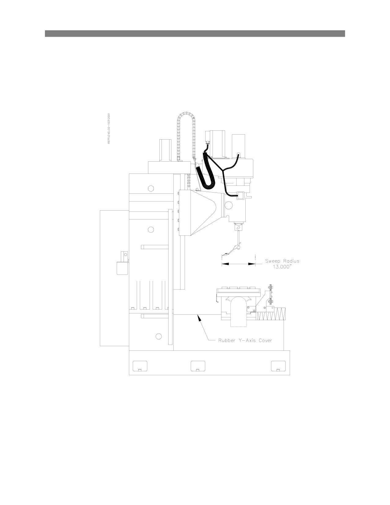
Sweeping the Spindle:
Remove any fixturing or tooling from the machine table and clean thoroughly.
Attach a mag base indicator to the bottom of the spindle. Make sure that the mag base is attached in
such a way that the spindle is able to be rotated 360 degrees without interference.
Use the following illustration for a visual reference on installing and using the Mag base indicator
correctly.
Left Side
Maintenance
4-10
F65 Manual
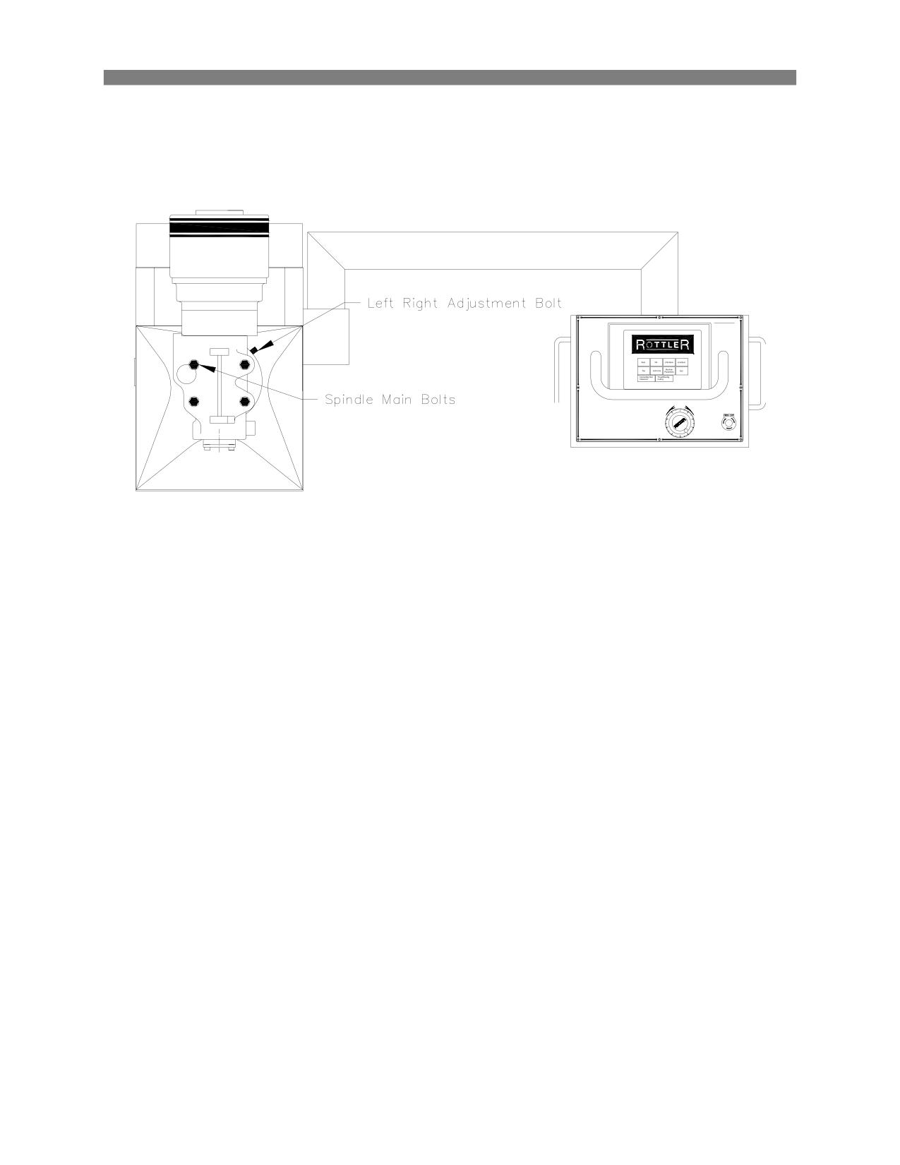
Loosen the four Spindle Main Bolts slightly. Using the Adjustment bolt on the right hand side of the
spindle head, sweep the spindle to within +/- .0002 Left to Right. Do not worry about the Front to Back
reading at this time as the Spindle Main bolts are not tight
Once the Left to Right has been aligned, tighten the Spindle Main Bolts to 80-ft. lbs. Verify the Left to
Right sweep again to make sure it did not change while tightening the Spindle Main bolts.
SAFETY CHECK
PROGRAM #
ENGINE BLOCK SECURE
GUARDS
CUTTERHEAD SECURE
TOOL SET & SECURE
FEED RATE SET
R.P.M. SET
OUT
IN
WARNING:
ALL MOVES ON THIS MACHINE ARE MADE UNDER POWER AND HAVE ENOUGH
FORCE TO SEVERELY INJURE ANY PART OF THE HUMAN BODY.
OF UNCONTROLLED MOVEMENTS.
AS WITH ALL ELECTRONIC CONTROLLED MACHINES, THIS MACHINE IS CAPABLE
THE CONTROL PANEL.
KEEP ALL PERSONNEL AWAY FROM CUTTING AREA ANYTIME SOMEONE IS NEAR
OPERATOR IS AWAY FROM MACHINE.
ALWAYS USE "CONTROL LOCKOUT" WHEN WORKING AROUND CUTTING AREA, OR
DO NOT INSTALL SCREEN SAVERS ON THIS MACHINE.
THE MACHINE IS MOVING.
MACHINE GUARD MUST REMAIN BETWEEN OPERATOR & CUTTERHEAD AT ALL TIMES
Check the Front to Back sweep it should be within .0005. If it is not, the Vertical gibs may need
adjustment.
Maintenance
4-11
F65 Manual
Vertical Gib Adjustment:
Gib adjustments can affect the sweep of the spindle front to back. With the indicator in the 6 O’clock
position (as you face the front of the machine) tightening the vertical gibs will lessen the pressure on the
indicator probe. Loosening the gib will increase the amount of pressure on the indicator probe.
Example: If you have a reading of 0.0 on the indicator at the 6 O’clock position and -.002” in the 12
O’clock position, tightening the gibs will bring the front of the spindle up. Adjust the gibs until you are
within the factory specified .001” deviance.
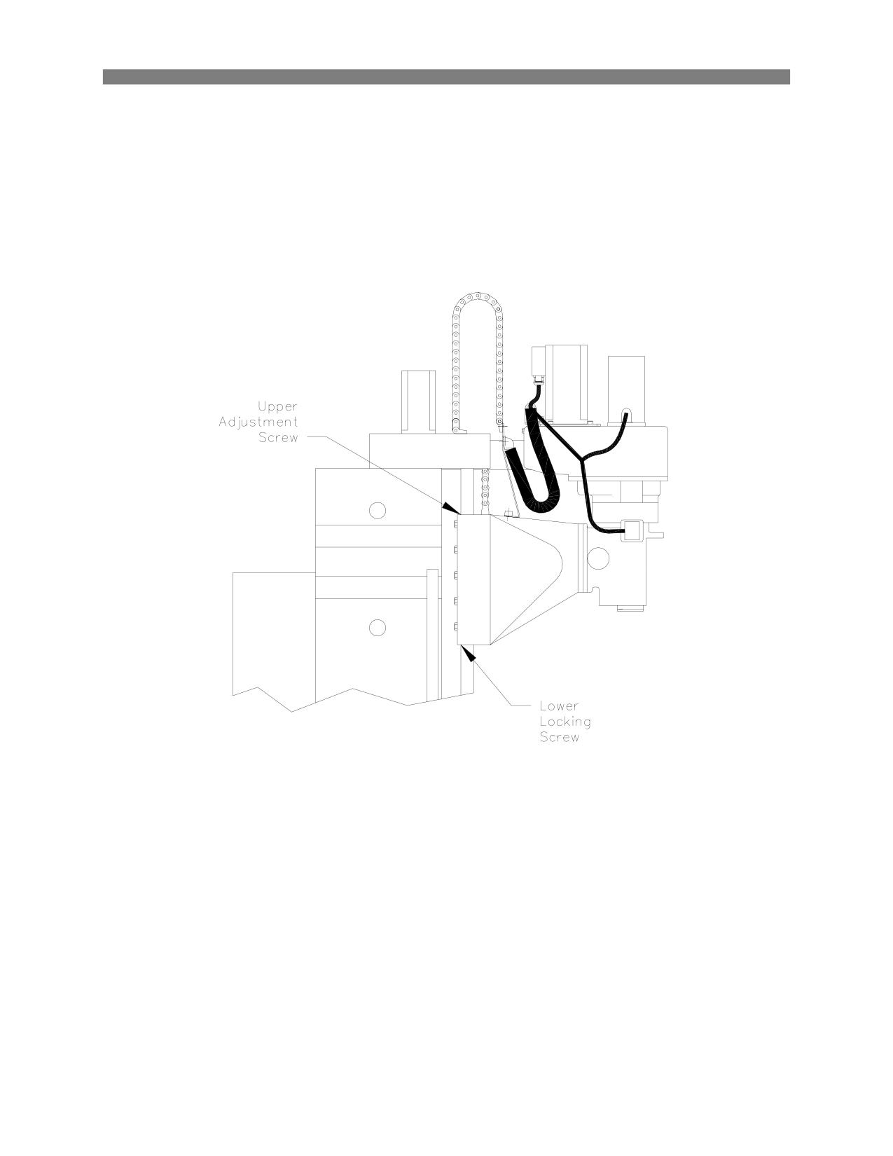
To adjust the vertical gibs locate the screw at the top and bottom of the gibs.
Tightening Gibs:
To tighten the gibs, loosen the lower screw. Start tightening the top screw until the correct alignment is
achieved. When the correct alignment is achieved, tighten the lower screw to lock the adjustment in
place.
Note: Adjusting the gibs too tight will cause sticktion and erratic movement in the vertical travel.
Loosening Gibs:
To loosen the gibs, loosen the top screw. Start tightening the lower screw until the correct alignment is
achieved. When the correct alignment is achieved, tighten the upper screw to lock adjustment in place.
Note: Having the gibs too loose will cause erratic bore size and finish.
If you do not know how tight or loose the gibs are adjusted, you can remove the way wipers from the top
of the gib. When you look in at the gib you will see a horizontal scribe line on most of the gibs. This can
be aligned with the internal casting for a starting point. The gibs may need further adjustment at this
point. This is only recommended as a starting point.
If there are any questions on this procedure contact Rottler Manufacturing Service Department.
Maintenance
4-12
F65 Manual
Performance Fixture Line-Up:
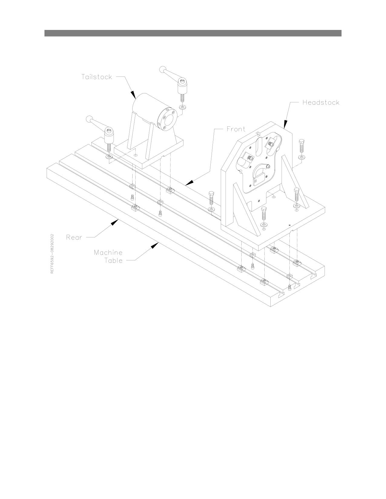
Install the keys for the Head and Tail Stock into the machine bed as shown below. Place the Head and
Tail Stock onto the machine table. Install the hold down bolts but do not tighten them down.
Push the head and tail stock toward the rear of the machine until the their keys but up against the table
key ways. Snug the hold down bolts and handles. Attach a magnetic base and indicator to the spindle.
Run the indicator across the face of the head stock front to back. Adjust the fixture until the indicator runs
within .001”. Lock the hold down bolts in place. Run the indicator from top to bottom on the head stock. It
should be within .001”. If it is not, pull the fixture from the table and check for burrs or dings in the head
stock and table surface. Be sure there is not debris on the head stock or machine table. Re-install the
head stock and follow the previous procedure. Check the face of the head stock again to be sure it did
not move while tightening down the bolts.
Install the Main Bar though the tail stock and into the head stock. Run the indicator along the back side of
the bar. It should be within .002” through out the travel. Adjust the tail stock in or out as needed to align
the bar. Tighten down the locking handles. Run the indicator along the top of the bar. It should be within
.002”. If it is not, pull the fixture from the table and check for burrs or dings in the tail stock and table
surface. Be sure there is not debris on the tail stock or machine table. Re-install the tail stock and follow
the previous procedure. Check the bar again to be sure it did not move while tightening down the bolts.
Maintenance
4-13
F65 Manual
Performance Fixture Line-Up (Cam End Tunnel Boring):
Install the keys for the Head and Tail Stock into the machine bed as shown on previous page. Place the
Head and Tail Stock onto the machine table. Install the hold down bolts but do not tighten them down.
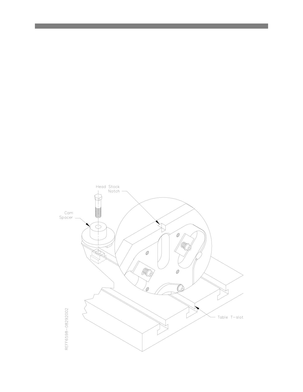
The center of the middle table key way needs to be lined up with the center of the Head Stock notch.
Using the electronic probe, touch the front side of the middle keyway. Zero the In/Out position. Using the
handwheel, move the table out until the probe touches the back side of the key way. Record the
numerical reading in the In/Out position box. Divide this number in half, handwheel the In/Out axis until
the numerical reading is the same as the halved number. Zero the In/Out axis again. The spindle is now
centered over the middle key way. Adjust the head stock In/Out until the center of the Head Stock notch
is at the In/Out zero position.
Attach a magnetic base and indicator to the spindle. Run the indicator across the face of the head stock
front to back. Adjust the fixture until the indicator runs within .001”. Lock the hold down bolts in place.
Run the indicator from top to bottom on the head stock. It should be within .001”. If it is not, pull the
fixture from the table and check for burrs or dings in the head stock and table surface. Be sure there is
not debris on the head stock or machine table. Re-install the head stock and follow the previous
procedure. Check the face of the head stock again to be sure it did not move while tightening down the
bolts.
Mount the End Truing V-End Truing Fixture (650-3-31) to the Head stock. Mount the block to the Truing
Fixture. The above procedure has aligned the fixture so the main bore in on the same center line as the
middle keyway.
Install the Cam spacer into the middle keyway. Place the bottom Cam Bore on the block over the cam
Spacer with the correct bushing installed. This will put the Cam Bore in line with the Main bore.
Troubleshooting
5-1
F65 Manual
Chapter 5 Troubleshooting:
Options
6-1
F65 Manual
Chapter 6 Machine Parts:
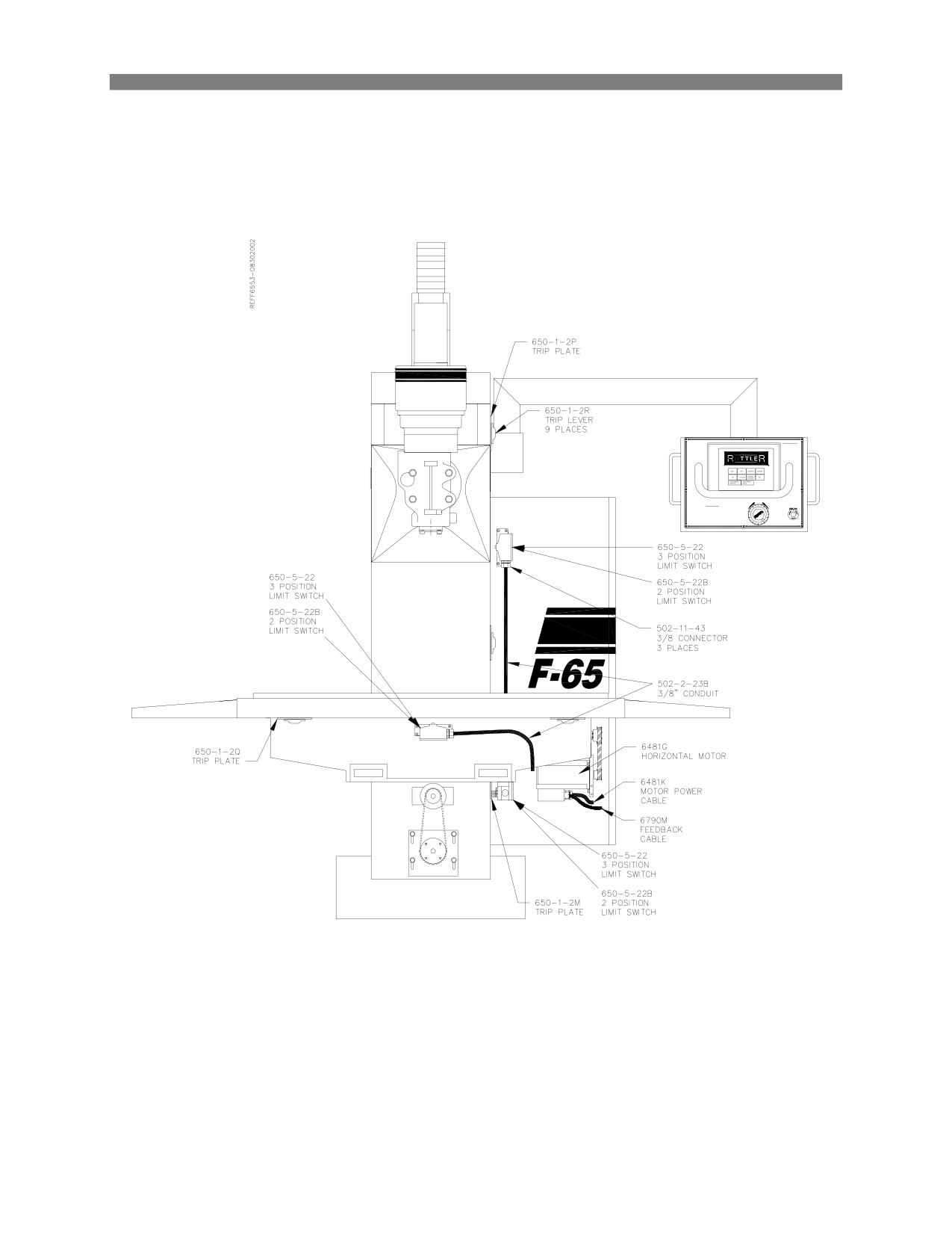
F65 Front View:
SAFETY CHECK
WARNING:
Options
6-2
F65 Manual
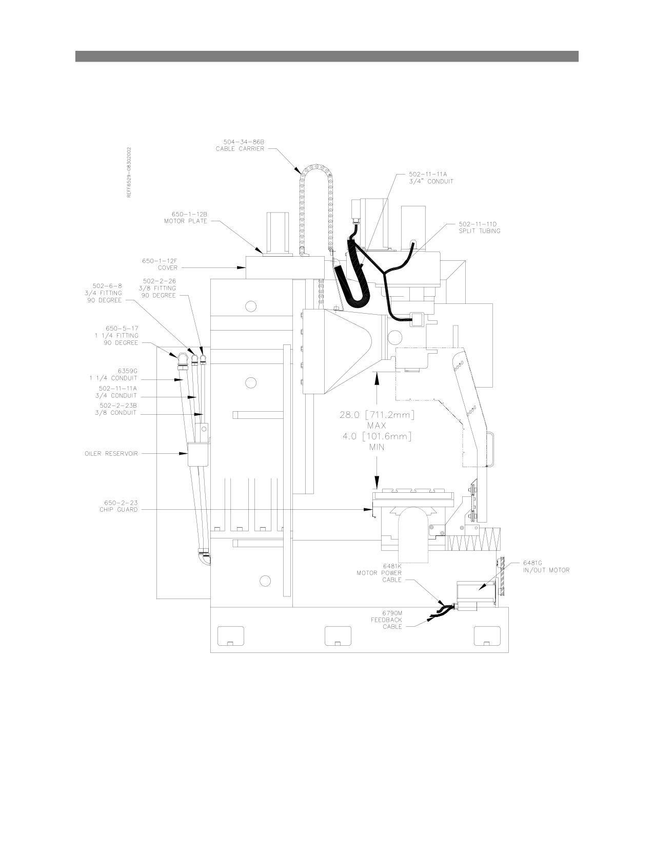
Drive Motors and Switches:
SAFETY CHECK
WARNING:
Options
6-3
F65 Manual
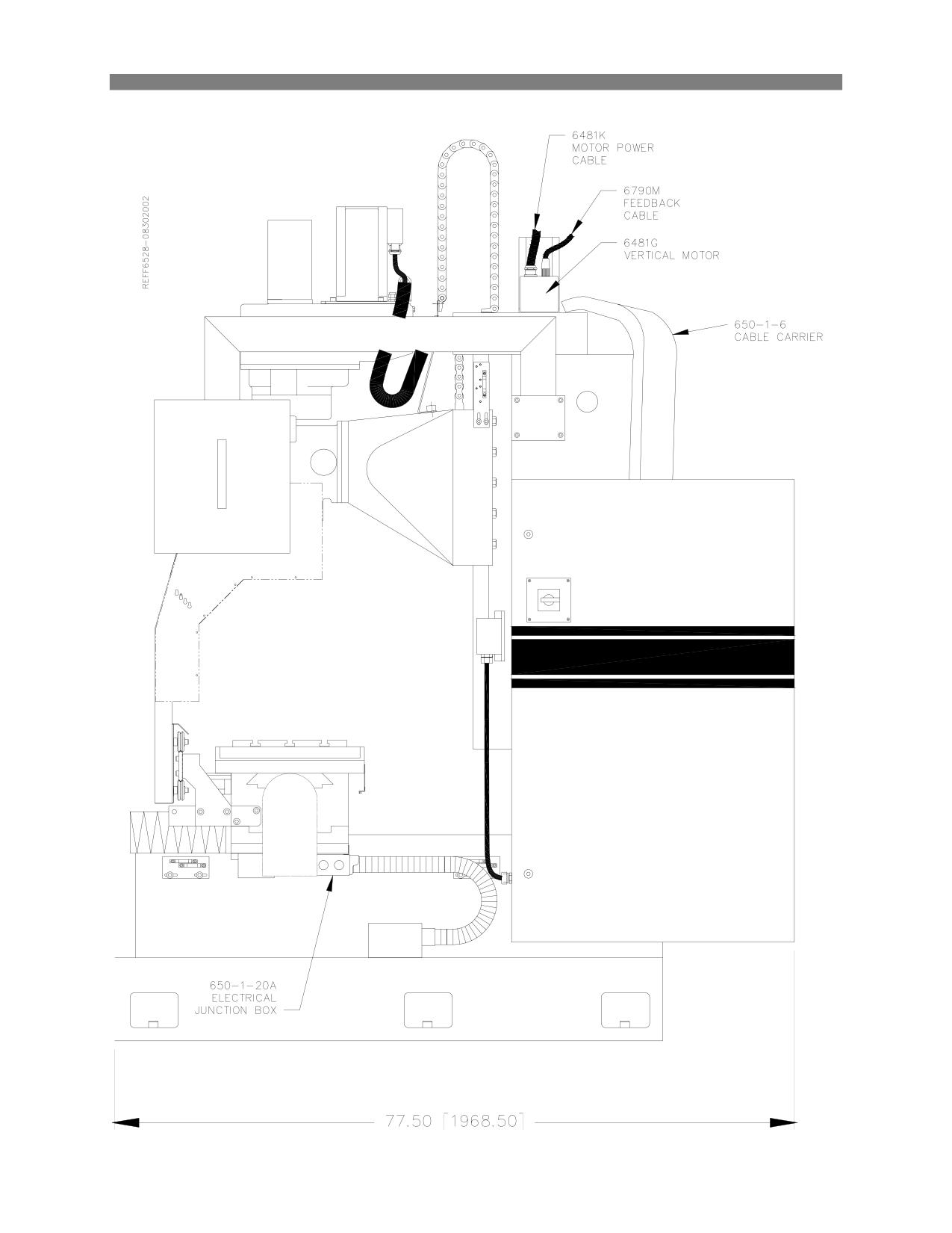
F65 left Side View:
Options
6-4
F65 Manual
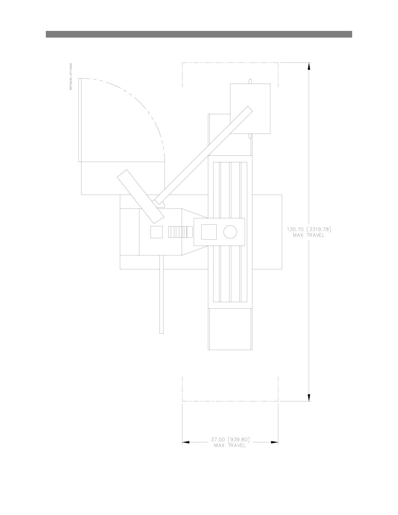
F65 Right Side View:
Options
6-5
F65 Manual
F65 Top View:
Options
6-6
F65 Manual
Electrical Panel:
Options
6-7
F65 Manual
F65 Control Panel:
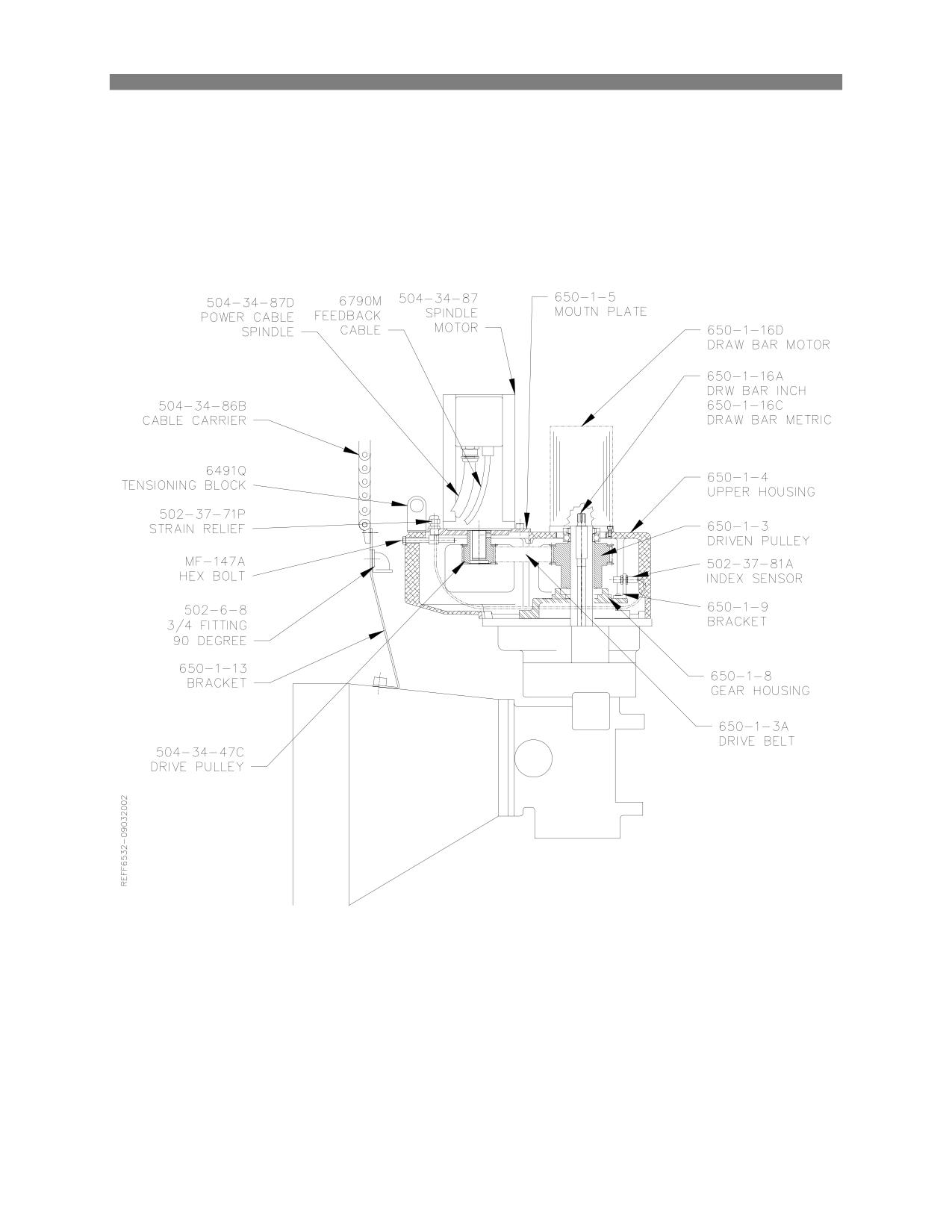
Options
6-8
F65 Manual
Upper Belt Housing:
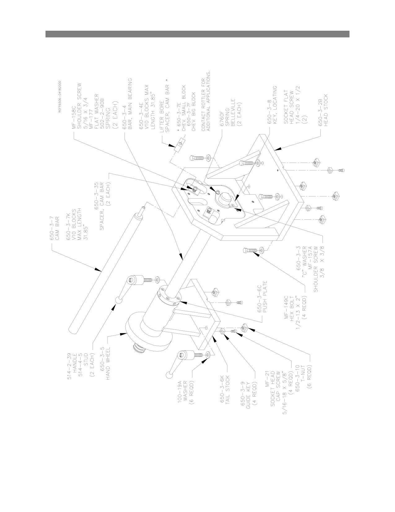
Options
6-9
F65 Manual
Options:
Performance Fixture 650-3-1:
Options
6-10
F65 Manual
Options
6-11
F65 Manual
Lifter Bore Spacers:
Application Chart:
650-3-7E
Chevy Small Block
650-3-7F
Chevy Big Block Intake (No spacer needed for exhaust)
650-3-7G
Ford 289-302-351W
650-3-7H
Ford 429-460
650-3-7J
Chrysler Small Block (Factory Race Block - 48 degrees)
Production small blocks use the smaller slot.
650-3-7N
42-Degree Chevy Aurora
650-3-7P
43-Degree Chevy Aurora
650-3-7Q
44-Degree Chevy Aurora
The following block lifters are at 45 degrees and do not require a lifter bore spacer: Ford 390/427,
351C/400C, Chrysler 383/400, 413/426W/440, 426 HEMI, Chev Big Block (exhaust).
Options
6-12
F65 Manual
Cam Bearing Locators:
Application / Selection Chart:
ASSY.
APPLICATION
LOCATOR NUMBERS
LOCATOR DIAMETER
QTY
NUMBER
650-3-19
SMALL BLOCK CHEV
283327/350/400
2.0090/2.0110 BORE #5
650-3-14 BORE #5
2.0085 DIA.
1
2.0190/2.0210 BORE #1
650-3-14G BORE #1
2.0185 DIA.
1
650-3-19A
BIG BLOCK CHEV
396/427/454
2.1295/2.1305 BORE #5
650-3-14A BORE #5
2.1290 DIA.
1
2.1395/2.1405 BORE #1
650-3-14H BORE #1
2.2390 DIA.
1
650-3-19B
BIG BLOCK FORD
(CHEV SB ROLLER BEARING)
650-3-14B
2.2480 DIA.
2
2.2485/2.2505 BORE
650-3-19C
SMALL BLOCK FORD
260/289/302/351W
2.1440/2.1450 BORE #5
650-3-14D BORE #5
2.1435 DIA.
1
2.2041/2.2051 BORE #1
650-3-14C BORE #1
2.2036 DIA.
1
650-3-19D
351M FORD
2.1440/2.1450 BORE #5
650-3-14D BORE #5
2.1435 DIA.
1
2.2995/2.2505 BORE #1
650-3-14B BORE #1
2.2490 DIA.
1
650-3-19E
SMALL BLOCK CHRYSLER
318/340/360
1.6920/1.6930 BORE #5
650-3-14F BORE #5
DIA.
1
2.1295/2.1305 BORE #1
650-3-14E BORE #1
2.1290 DIA.
1
650-3-19F
BIG BLOCK CHRYSLER
383/426/440
1.8795/1.8805 BORE #5
650-3-14J BORE #5
DIA.
1
2.1295/2.1305 BORE #1
650-3-14E BORE #1
2.1290 DIA.
1
650-3-19G
PROSTOCK BB CHEV
2.4780/2.4790 BORE
650-3-14K
2.4775 DIA.
2
650-3-19H
PROSTOCK BB CHEV
2.6733/2.6743 BORE
650-3-14L
2.6728 DIA.
2
650-3-19J
CHEV SB ROLLER BEARING
1.8745/1.8750 BORE
650-3-14M
1.8740 DIA.
2
650-3-19K
PONTIAC 455
2.2297/2.0317 BORE
650-3-14N
2.0292 DIA.
2
650-3-19L
CHEV CNC BOW-TIE BLOCK
2.1200/2.1210 BORE
650-3-14P
2.1195 DIA.
2
650-3-19M
CHEV SB ROLLER BEARING
2.2827/2.2831 BORE
650-3-14Q
2.2822 DIA.
2
650-3-19N
CHEV CNC BOW-TIE BLOCK
1.9990/2.0010 BORE
650-3-14R
1.9985 DIA.
2
650-3-19P
ALUMINUM LS1 BLOCK
2.3223 / 2.3224
650-3-14S
2.2332 DIA.
2
650-3-19Q
FORD 390 BLOCK
2.3095 / 2.3105 BORE #1
650-3-14T
2.3085 DIA.
1
2.2495 / 2.2505 BORE #5
650-3-14B
2.2490 DIA.
1
650-3-19R
ROLLER BEARING
650-3-14U
2.4980
2
2.4985 / 2.5005
650-3-19T
BUICK/CAD/OLDS/PONTIAC
1978-84
2.1670 / 2.1680 #1
650-3-14W
2.1670 DIA.
1
2.0870 / 2.0880 #5
650-3-14X
2.0870 DIA.
1

Options
6-13
F65 Manual
650-3-19U
CAM BORES
650-3-14V
1.9685 DIA
2
1.9675 / 1.9685
Main Bearing Locators:
Selection List:
Note: Each locator covers two bearing diameters (‘A’ and ‘B’). The unused diameter MUST be
placed INSIDE the block to prevent interference with the Index Plates>
Part
Make
Displacement
Main Locator Diameter
Number
CU. IN.
“A” Dia.
“B” Dia.
502-1-47A
Chev V/8
302/327/350(1968 and
2.6391 +.0010/-.0000
newer)/4.3L V/6
Chev V/8
400 SB/3.4L V/6
2.8390 +.0010/-.0000
502-1-47B
Chev V/8
396/ 427/ 454
2.9365 +.0010/-.0000
Buick V/6
231
2.6855 +.0010/-.0000
502-1-47C
Buick/Olds/Pontiac V/8
350/ 389/ 400
3.1865 +.0010/-.0000
Buick/Pontiac V/8
421/ 428/ 455
3.4365 +.0010/-.0000
502-1-47D
Ford V/8
351C
2.9402 +.0010/-.0000
Ford V/8
351M / 351W/ 429/ 460
3.1907 +.0010/-.0000
502-1-47E
Ford V/8
289/ 302
2.4397 +.0010/-.0000
Mopar V/8
360
3.0010 +.0010/-.0000
502-1-47F
Mopar V/8
318/ 340
2.6910 +.0010/-.0000
Mopar V/8
426/ 440
2.9410 +.0010/-.0000
502-1-47G
Chev V/8
283/302/327(thru 1967)
2.4892 +.0010/-.0000
Chev V/8
5.3L('99 and newer)
2.7490 +.0010/-.0000
502-1-47H
SPECIAL APPLICATION
3.3137 +.0010/-.0000
502-1-47J
Porche V8
928
2.9510 +.0010/-.0000
502-1-47K
GM
6.5 L/395 DIESEL
3.1420 +.0010/-.0000
502-1-47L
Ford
4.6
2.8491+.0010/-.0000
ZETGC
2.4528 +.0010/-.0000
502-1-47M
Honda
1.8 L
2.3216 +.0010/-.0000
Mitsubishi
2.0 L
2.4002 +.0010/-.0000
502-1-47N
AMC Chrysler
2.9396 +.0010/-.0000
Options
6-14
F65 Manual
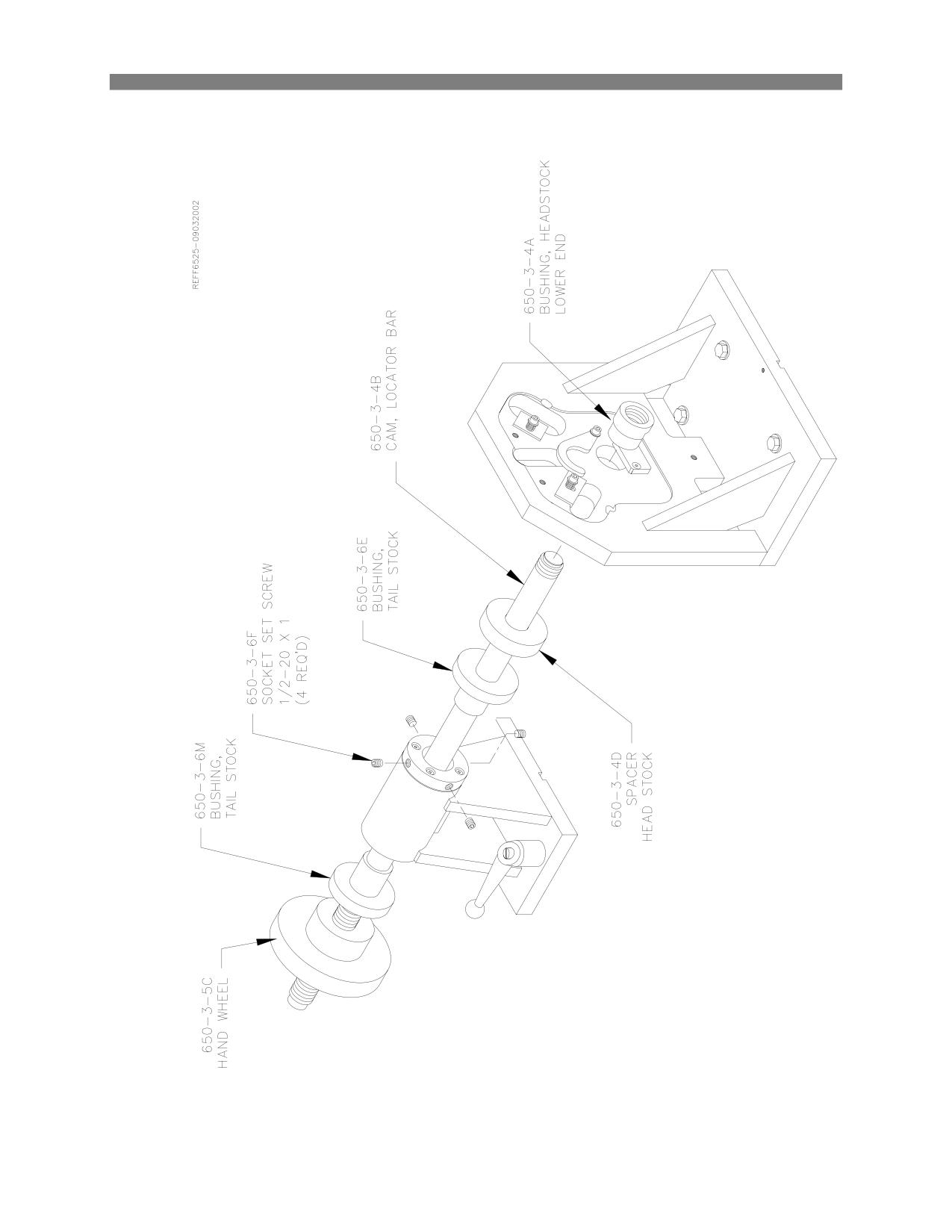
Options
6-15
F65 Manual
Lower End machining Package 650-3-1A:
Options
6-16
F65 Manual
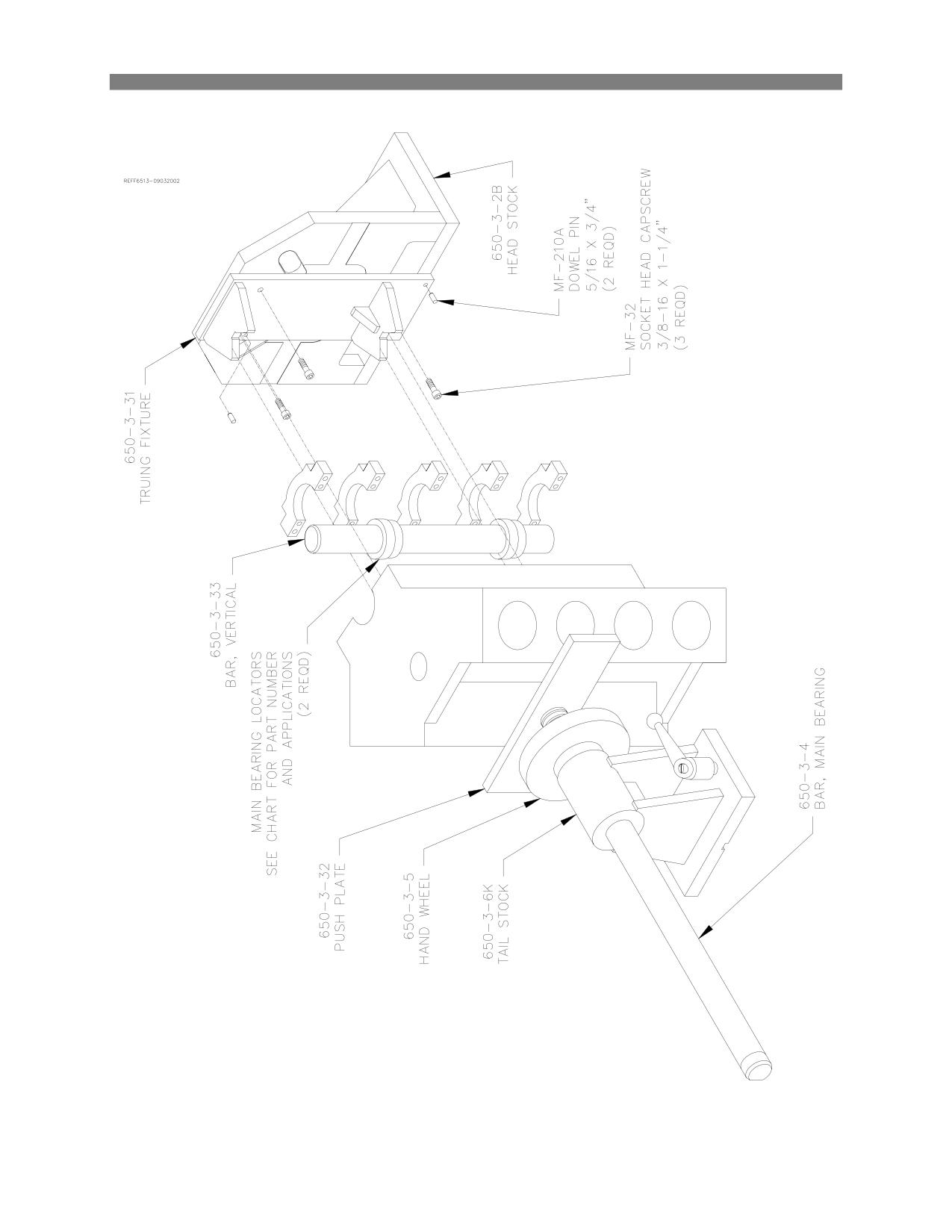
Block End truing Fixture 650-3-30:
Options
6-17
F65 Manual
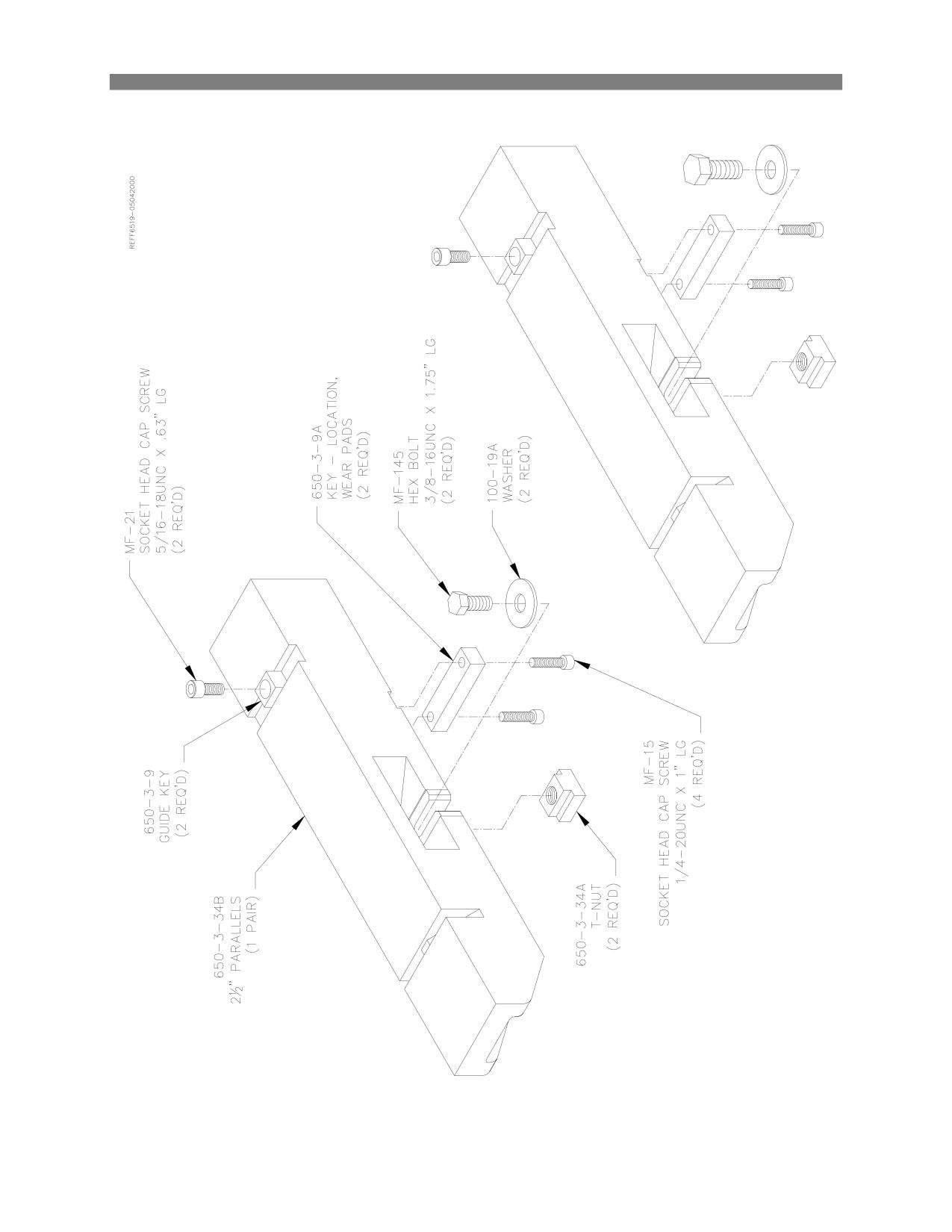
2 ½” Wear pad Assembly 650-3-34:
Options
6-18
F65 Manual
Manual V6/V8 Combination Fixture 502-1-72H:
Caution: Handle block and fixture with Extreme care and guidance. A block hoist is required.
Mishandling of a heavy engine block and fixture could result in the dropping of parts and possible
personal injury. Be Careful!
The Model 502-1-72H manual V6/V8 combination fixture is a fast, simple and universal system to
properly and accurately hold most 60 degree V-type engine blocks for either cylinder boring or deck
surfacing.
Boring Machine Application
Note: The block must have the main bearing caps in place and torqued.
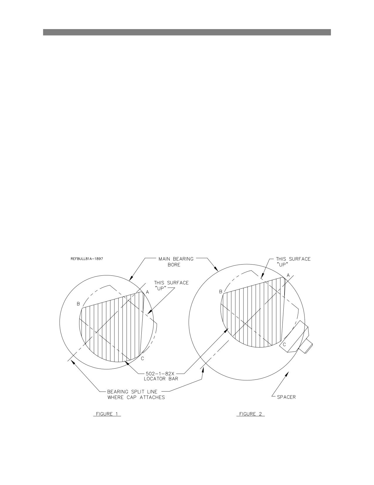
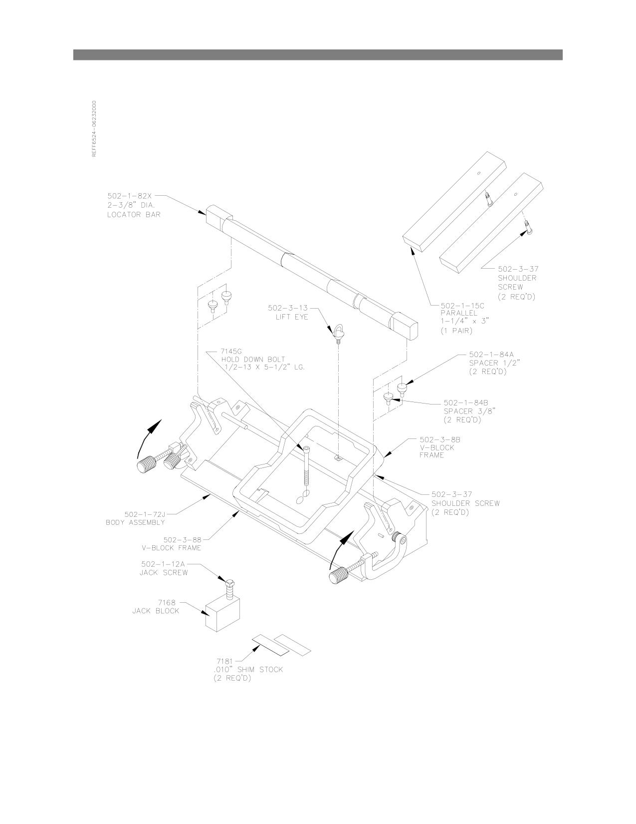
Care must be taken to assure the contact edges of the locator bar are near the cap split line. A pair of
3/8” and ½” spacers are provided for blocks with large main bearing bores, to enable the bar to locate
near the main bearing split line. (See figure 2)
V-blocks:
(blocks with main bearing center lines no more than ½” higher than the pan rail plane) are mounted with
the 502-3-8B V-block frame in place. Select the 90-degree option placement of the frame to suit block
length, or main bearing caps will interfere with frame. Rotate frame 90 degrees by moving its shoulder
screws to alternate set of holes.
Y-Blocks:
(blocks with main bearing center lines 2-3/8” to 3-1/2” higher than the pan rail plane) are mounted directly
on the fixture. Some Y-blocks (GM 60 degree) have too narrow pan rails and some have too low main
bearing location which will require the use of the 502-1-15C precision 1-1/4” x 3” parallel set to raise and
or support the block. Use the shoulder screw from the V-block frame and hook the parallels over the back
of the V-fixture.
This fixture may be easily repositioned on the support parallels (without a block in place) to shift from the
60 degree support surface to the 90 degree support surface or vice versa.
CAUTION: Extreme care must be taken by operator whenever handling large blocks. Large blocks may
cause fixture to tip when floated too far outward. We recommend leaving hoist attached when moving
these blocks. Large blocks should be lifted from the block bank surface. DO NOT use the 502-1-95 block
handler assembly on these blocks.
Normal Operating Procedure:
The normal operation procedure on smaller V-blocks is to first pick up the block. If using the optional 502-
1-95 block handler (see page 3.22), attach it to the block making sure the cam lifters are COMPLETELY
engaged, and that the lift hook is approximately centered in the block lengthwise. Place the 502-1-82X
locator bar through the main bearings and hoist the block into the fixture. Pulling the block towards you,
with the locator against the positioners, will prevent jamming in the slot of the guides during the loading
and unloading operations. The locator bar is positioned with the word ‘UP’ that is on the end of the bar
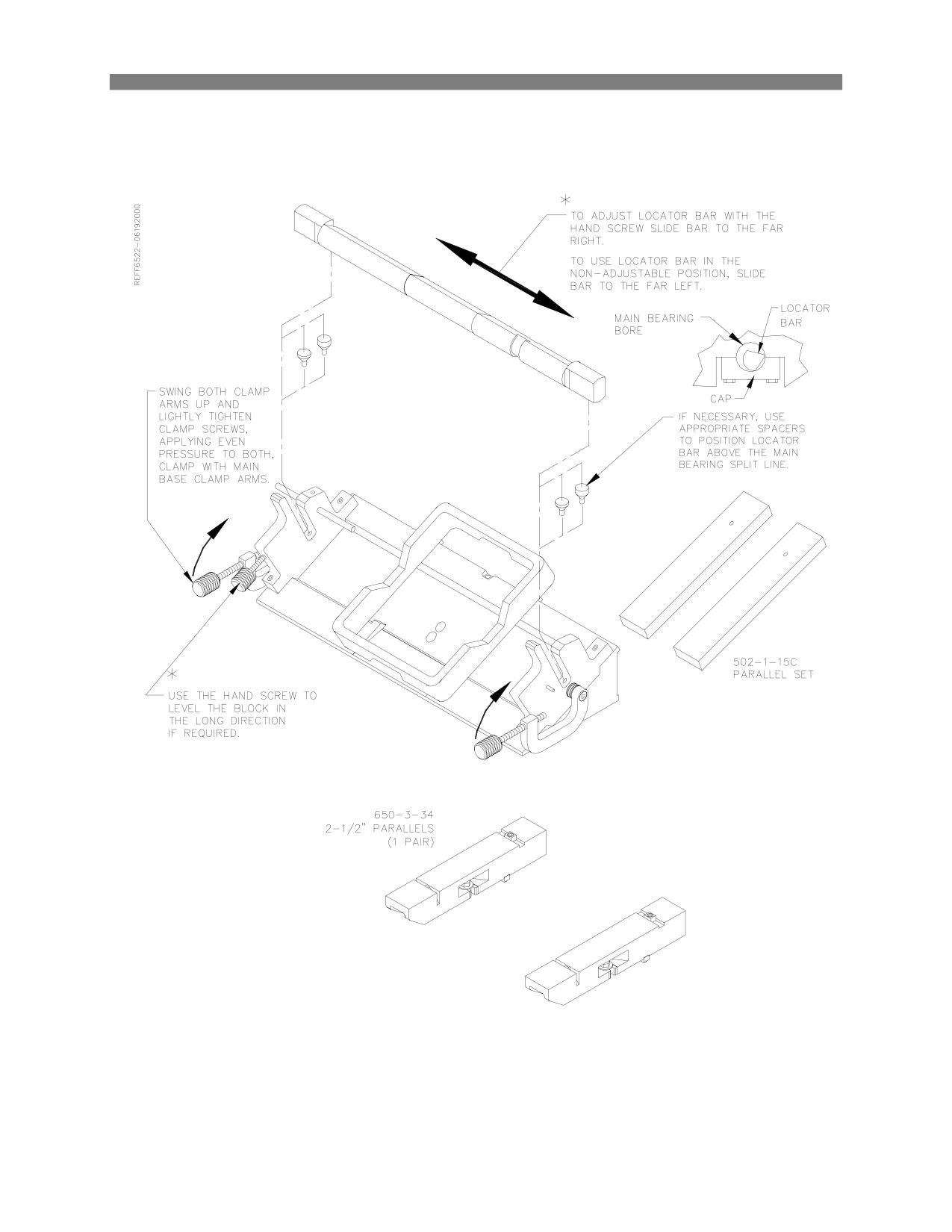
facing up and away from the operator. (see figure 1) After the locator bar is engaged in the positioners,
pivot block outwards as you lower it. Slide block to the far left (this is the non adjustable position).
Make sure the block is firmly seated in place and not resting on pan-rail burrs or other interference points.
Accurate seating can also be a problem with extremely warped, distorted blocks. Another cause of
problems is failure to remove main bearing inserts. The locator bar has a relief for blocks with a small
main bearing or seal. Rotate locator bar clamps into position & lightly tighten the hand screws, applying
even pressure to both. Clamp the block securely with the main base clamp arms.
Warped or distorted blocks may require leveling of the deck surface in the long direction. This is possible
with the hand-screw assembly in the left-hand bar positioner. Loosen both clamp hand-screws and slide
the locator bar to the far right position. Retighten both clamp hand-screws. Raise or lower the adjusting
Options
6-19
F65 Manual
hand-screw as required. For the non-adjustable position slide locator bar to the far left. (See illustration
page 3.15.)
Push fixture back into bore position. There is a guide block (502-1-105) attached to the bottom of the
fixture to aid in guiding the fixture along the support ways.
Operate the block clamp arms, bore, and pull fixture back to the load position.
Loosen locator bar handscrews and rotate clcamps out of the way. Lift the block, either from the deck
surface or with the optional 502-1-95 block handler (see page 3.22). Turn the block 180 degrees & reload
to duplicate the operation on the other bank.
After turning the engine block 180 degrees the locator bar must be twisted 180 degrees also. Again the
word ’UP’ must enter into the positioners facing up and away from the operator. (See figure 1).
Figure 1 502-1-82X main bearing locator bar indexes at point A. When bank is reversed and the bar is
twisted 180 degrees, point A still indexes the main bearing.
Point C holds the block down. When bank is reversed and the bar is twisted 180 degrees, point B holds
the block down.
Figure 2 502-1-82X main bearing locator bar indexes near bearing split line. Point C does not contact the
bearing cap but rests on matched spacers, that are provided to fit in the bar positioners slot. If there is a
means of holding the block down such as block clamp towers, this method may be used in large bores in
order to properly index near the bearing split line. If extreme care is used this method may be used to
index blocks without bearing caps attached. (Optional clamp down must be provided).
Options
6-20
F65 Manual
Manual Fixture Assembly 502-1-72H:
Options
6-21
F65 Manual
V6/V8 Manual Fixture Body Assembly 502-1-72J:
Options
6-22
F65 Manual
V6/V8 Manual Fixture Body Assembly 502-1-72J: (cont)
Options
6-23
F65 Manual
Options
6-24
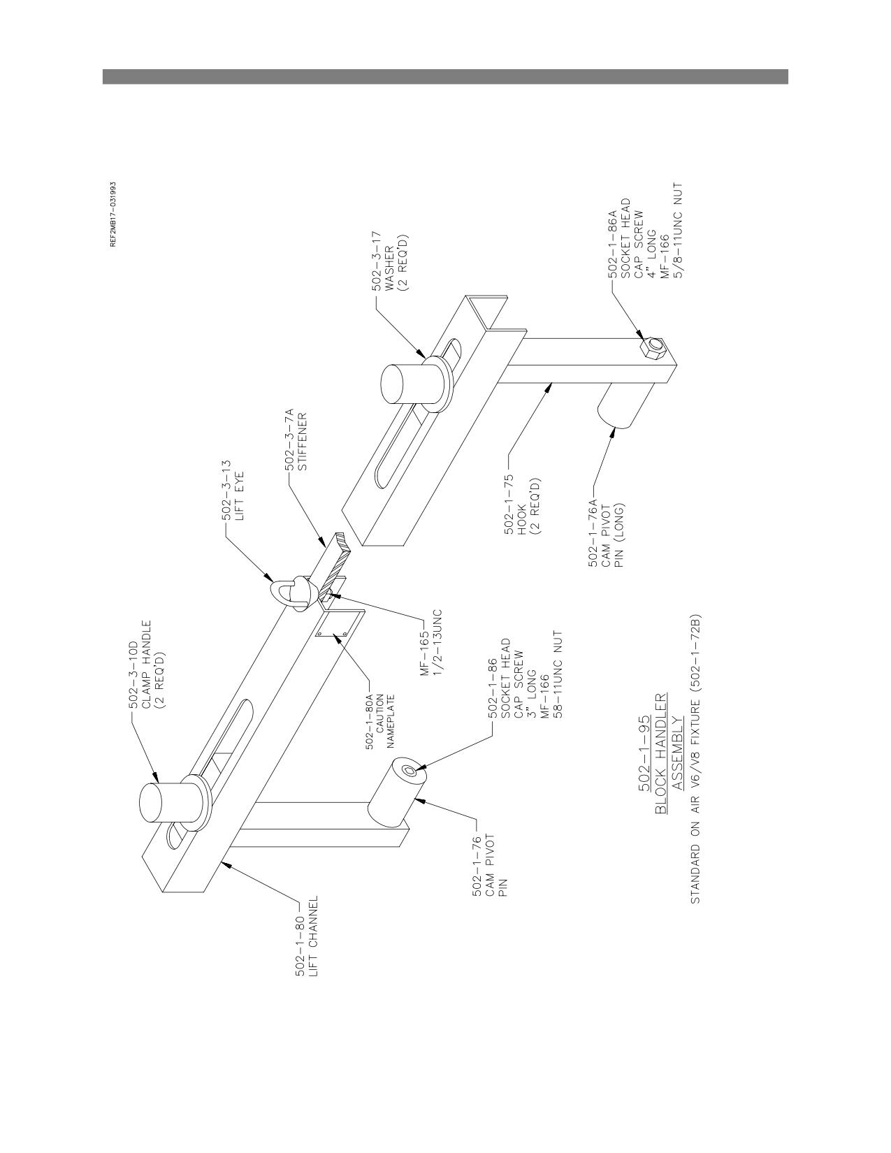
F65 Manual
Block Handler 502-1-95:
Options
6-25
F65 Manual
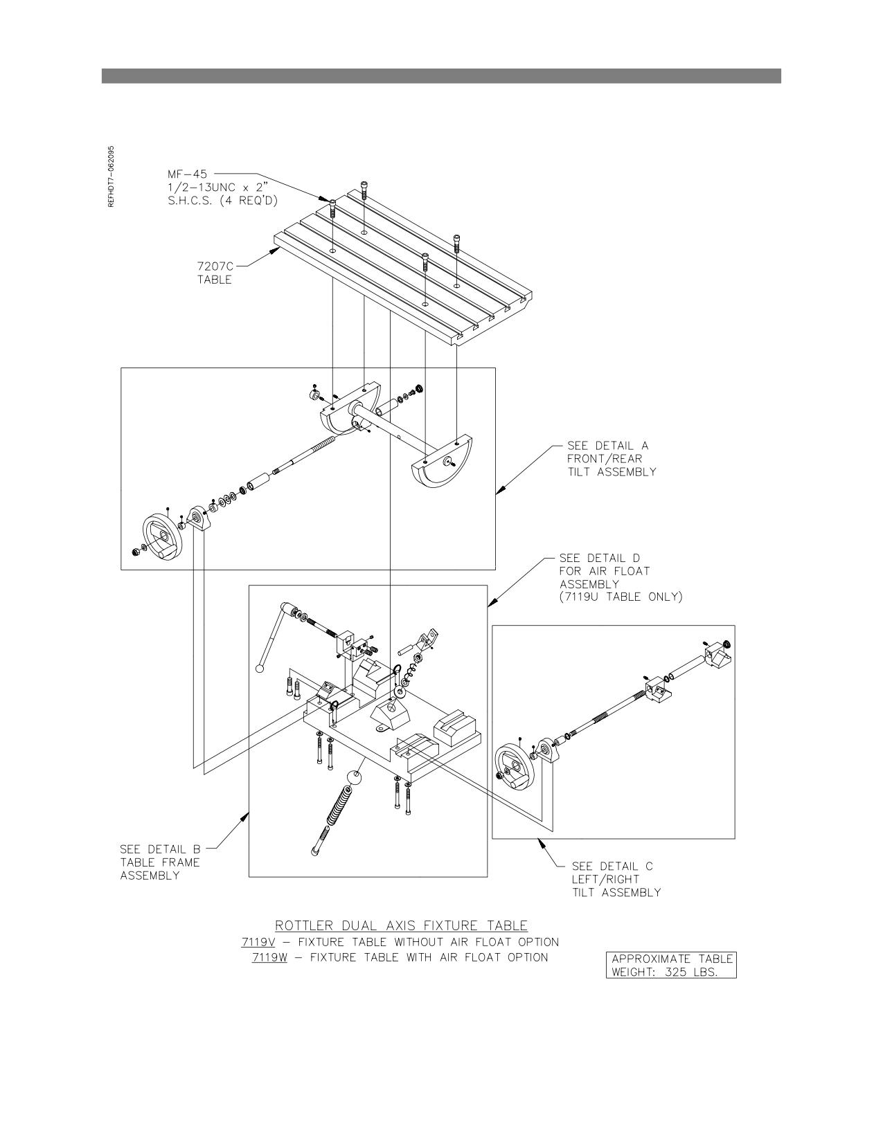
Dual Axis Leveling Table 7209M:
Options
6-26
F65 Manual
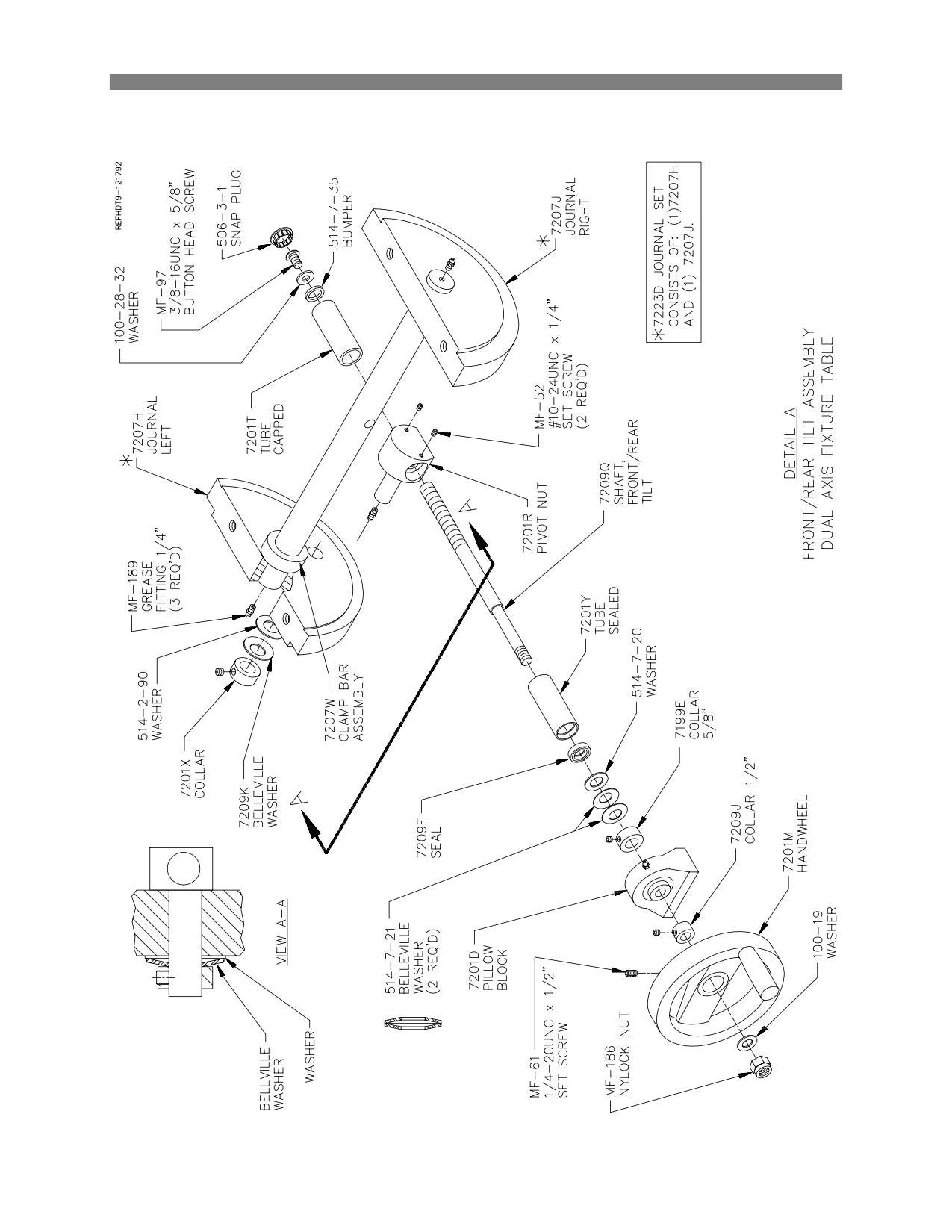
Front/Rear Tilt Assembly:
Options
6-27
F65 Manual
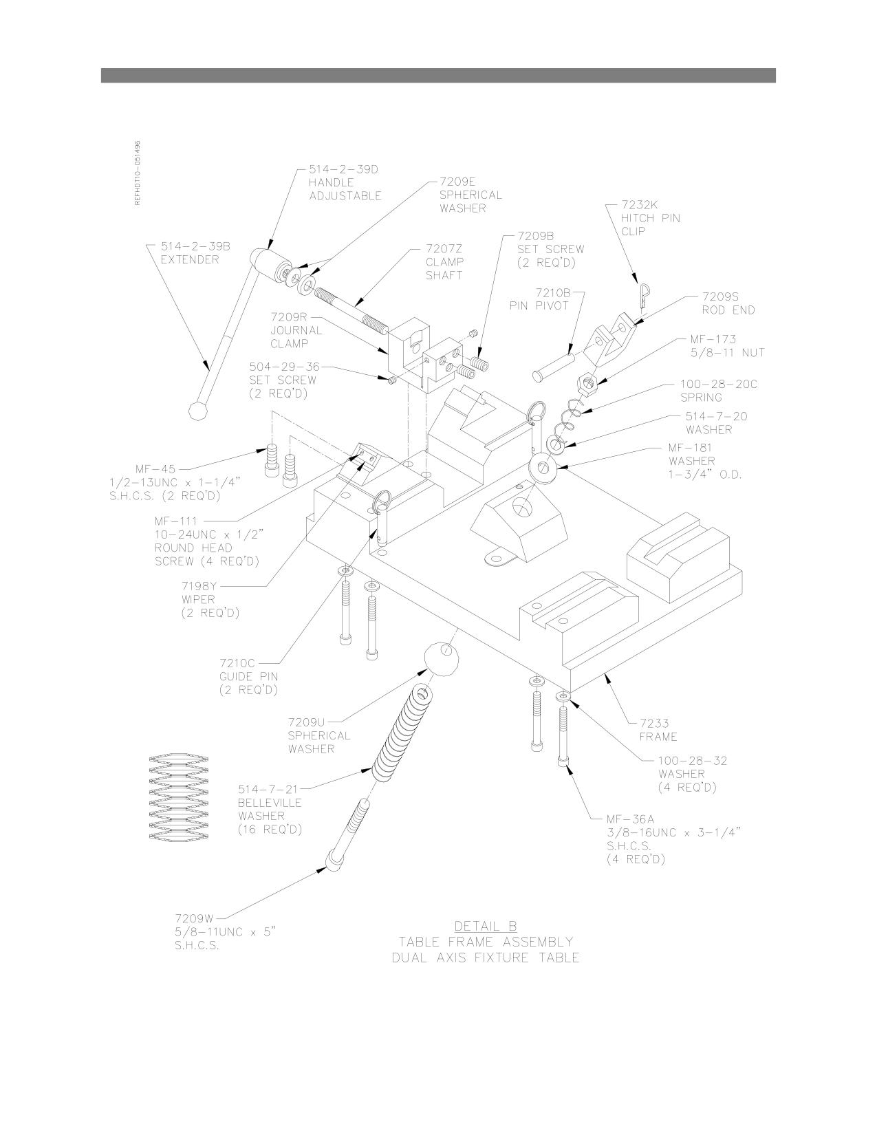
Table Frame Assembly:
Options
6-28
F65 Manual
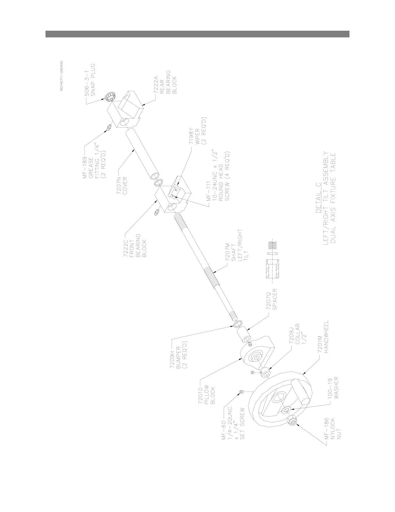
Left/Right Tilt Assembly:
Options
6-29
F65 Manual
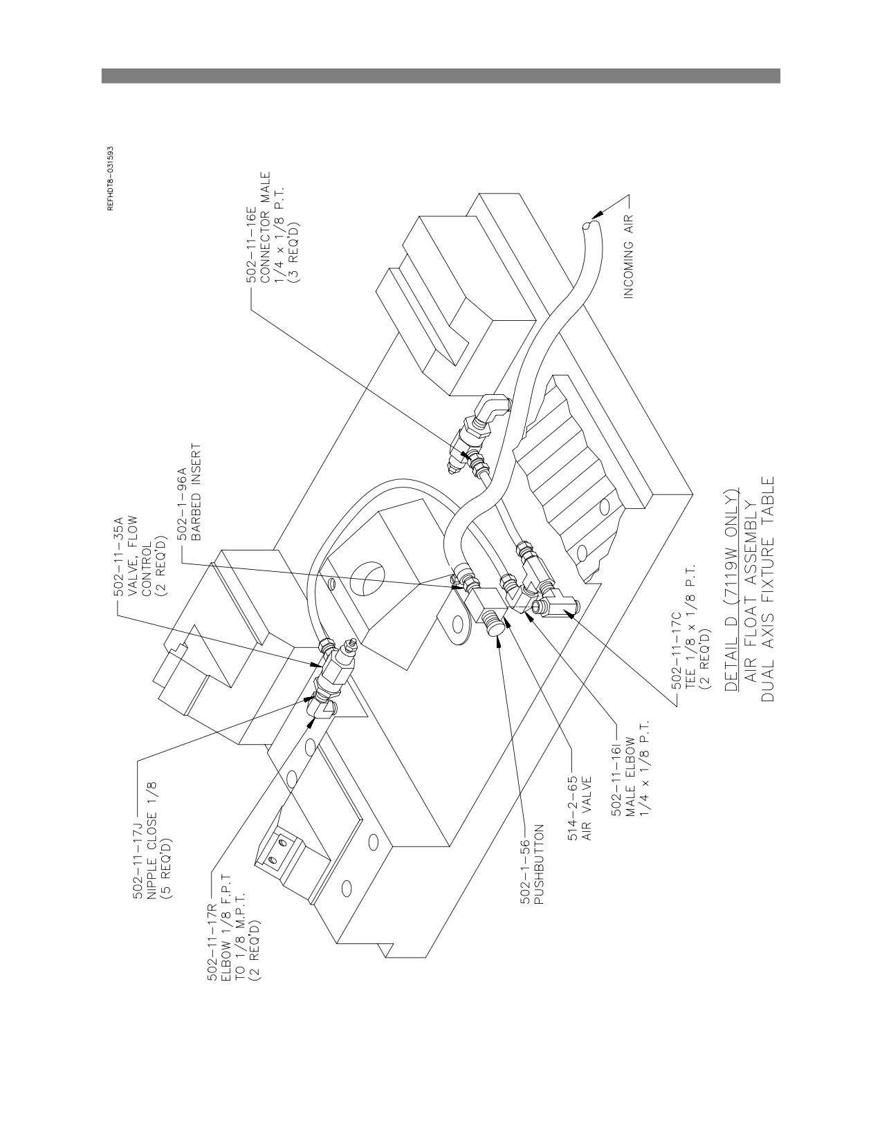
Air Float Assembly:
Options
6-30
F65 Manual
Dual Axis Leveling Table:
Adjustment Procedure:
Note: This fixture is set at the factory and should not require further adjustments. Adjustment is
required after any disassembly.
1. Secure table to Machine surface.
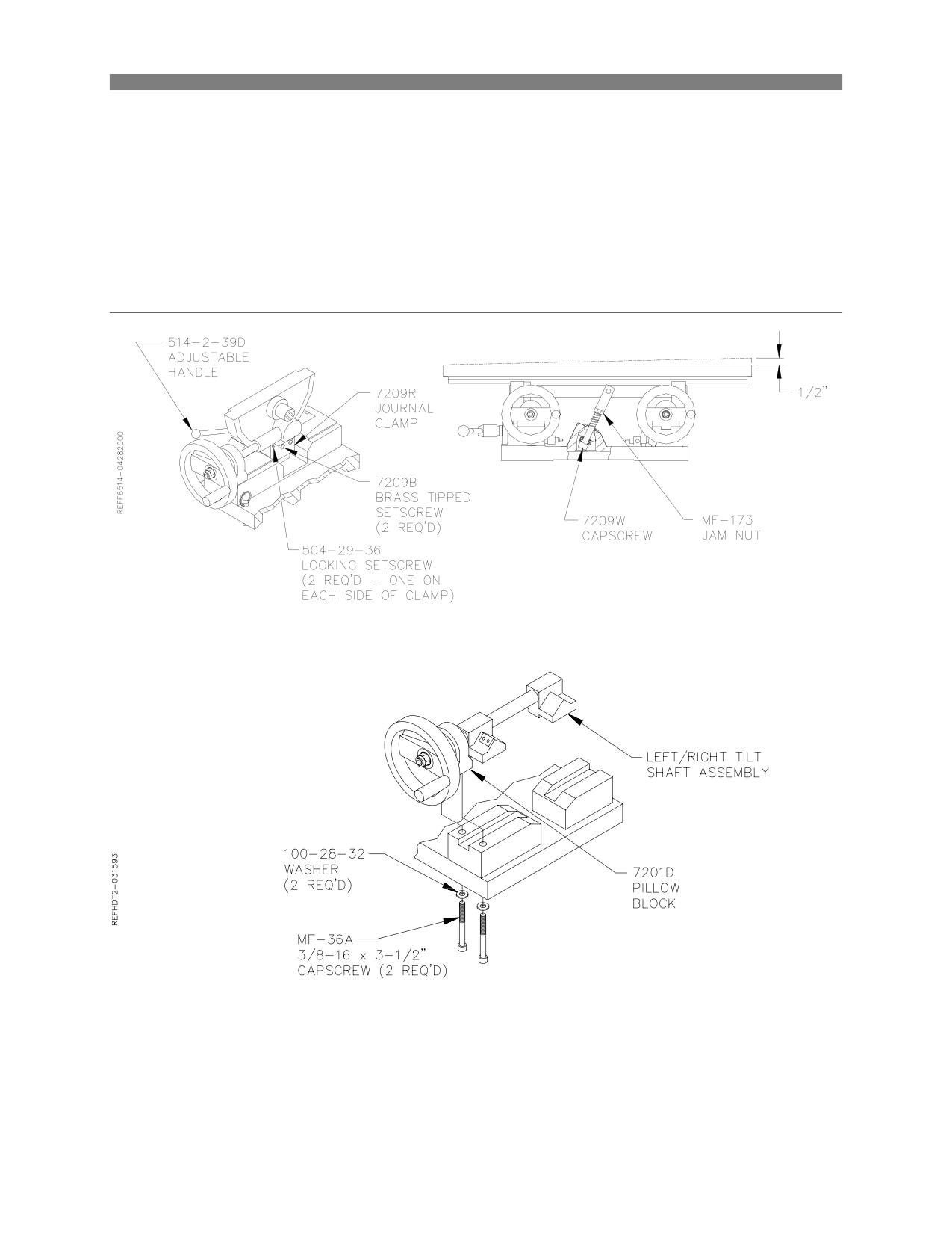
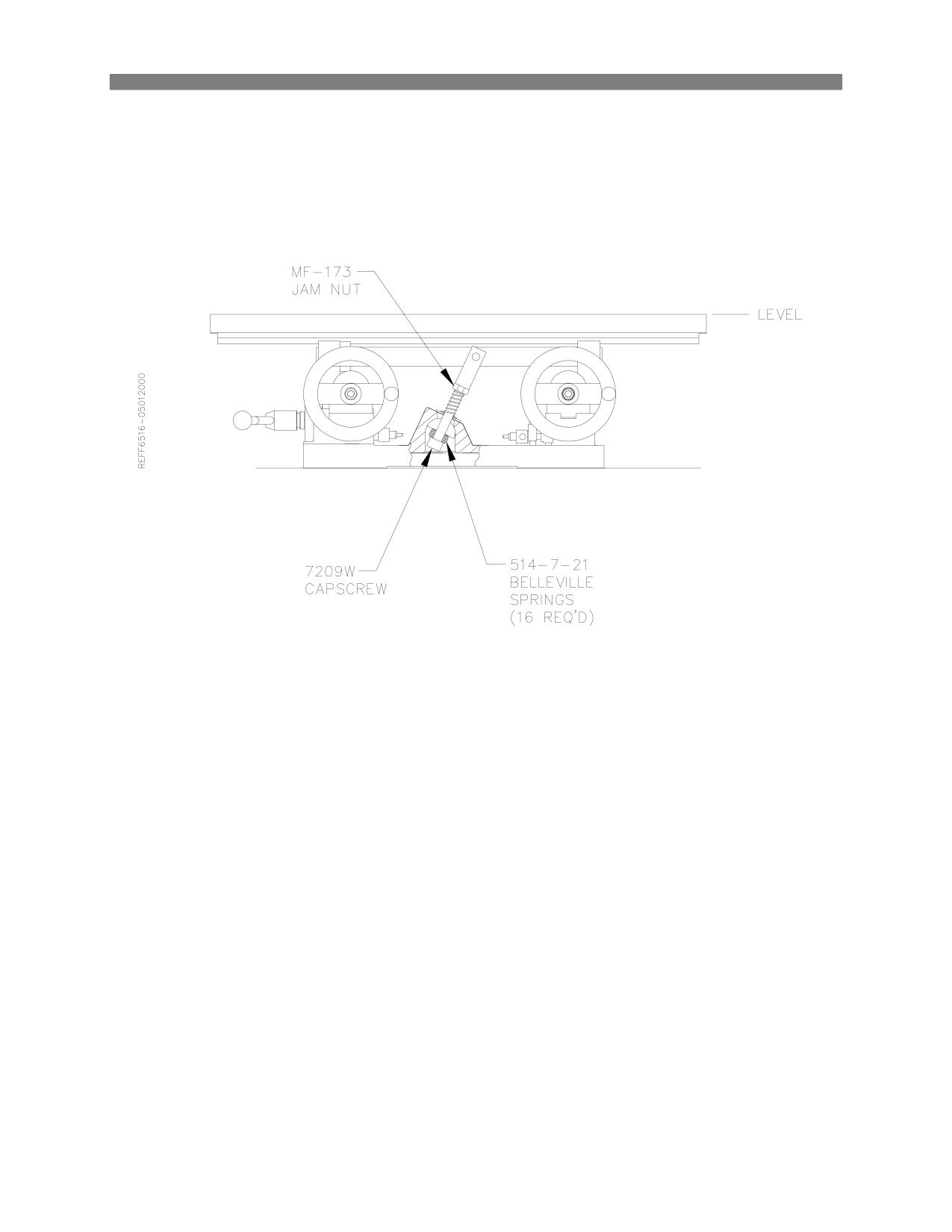
2. Level table in both directions. Loosen Jam nut (MF-173) and capscrew (7209W) on the table clamp.
Loosen adjustable handle (514-2-93D) on the left side of table. Loosen (2) locking set screws (504-
29-36) on both sides of journal clamp. Loosen (2) brass tipped set screws (7209B).
3. Using a hoist, raise right end of table top approximately ½”.
4. Remove (2) capscrews on right hand pillow block (7210D). Remove tilt shaft assembly from fixture.
Options
6-31
F65 Manual
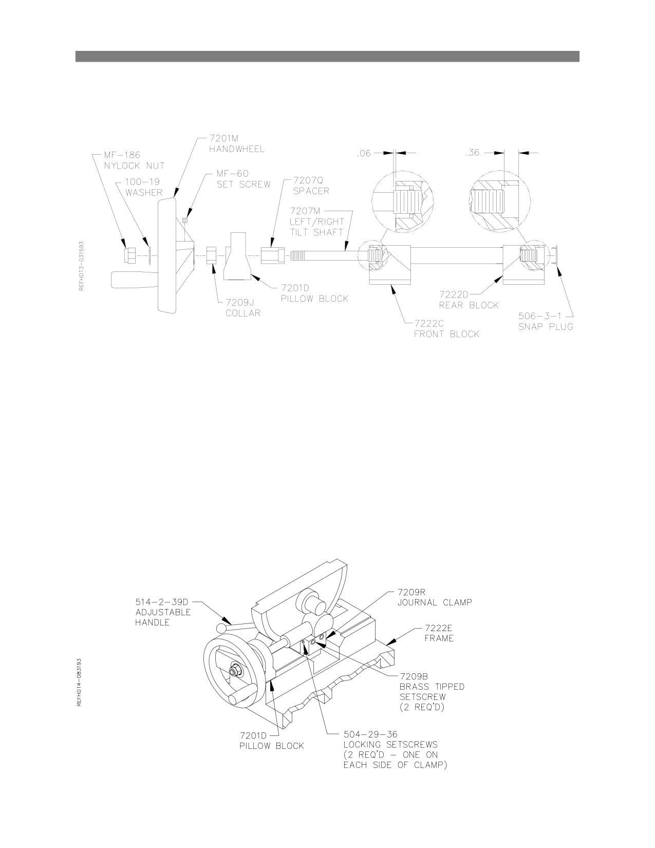
Remove nylock nut (MF-186) and washer (100-19) from shaft (7207M). Loosen set screw (MF-60) and
remove hand wheel (7201M). Slide spacer (7207Q) off tilt shaft. Remove snap plug (506-3-1) from rear
block (7207L).
5. Adjust assembly by threading blocks in or out to set them to dimensions shown below.
6. Reassemble left/right tilt shaft assembly.
7. Place tilt shaft assembly back into frame.
8. Lower table top into position. Reinstall (2) cap screws on right hand pillow block. Do not tighten
these screws yet.
9. Loosen bolts on left hand pillow block (7201D). Right hand pillow block should still be loose.
10. Loosen (2) bolts holding journal clamp (7209R) to frame (7209T).
11. Adjustable handle (514-2-39D) on left side of table and (2) locking set screws (504-29-36) on sides of
journal clamp should still be loose.
12. Turn (2) brass tipped set screws (7209B) in until the left hand journal is pushed all the way to the left.
Back off set screws until they just contact journal.
13. Tighten locking set screws on journal clamp and both pillow blocks.
14. Tighten mounting bolts on journal clamp and both pillow blocks.
Options
6-32
F65 Manual
15. Level table in both directions.
16. Adjustable handle (514-2-39D) on left side of table should still be loose.
17. Tighten cap screw (7209W) on table clamp to flatten it’s Belleville springs (514-7-21) then back off 3-
1/2 turns from tight. Tighten jam nut on table clamp.
18. Table should now travel both 1/8” min. up and 1/8” min. down from level in left/right tilt.
19. Check with shim stock to make sure that journals sit properly on frame at all four contact points.
Options
6-33
F65 Manual
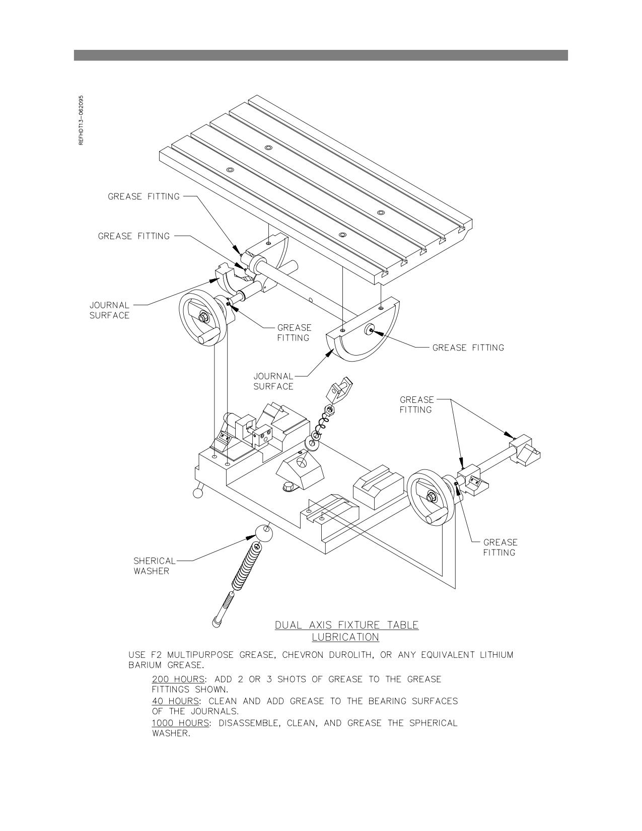
Lubrication:
Options
6-34
F65 Manual
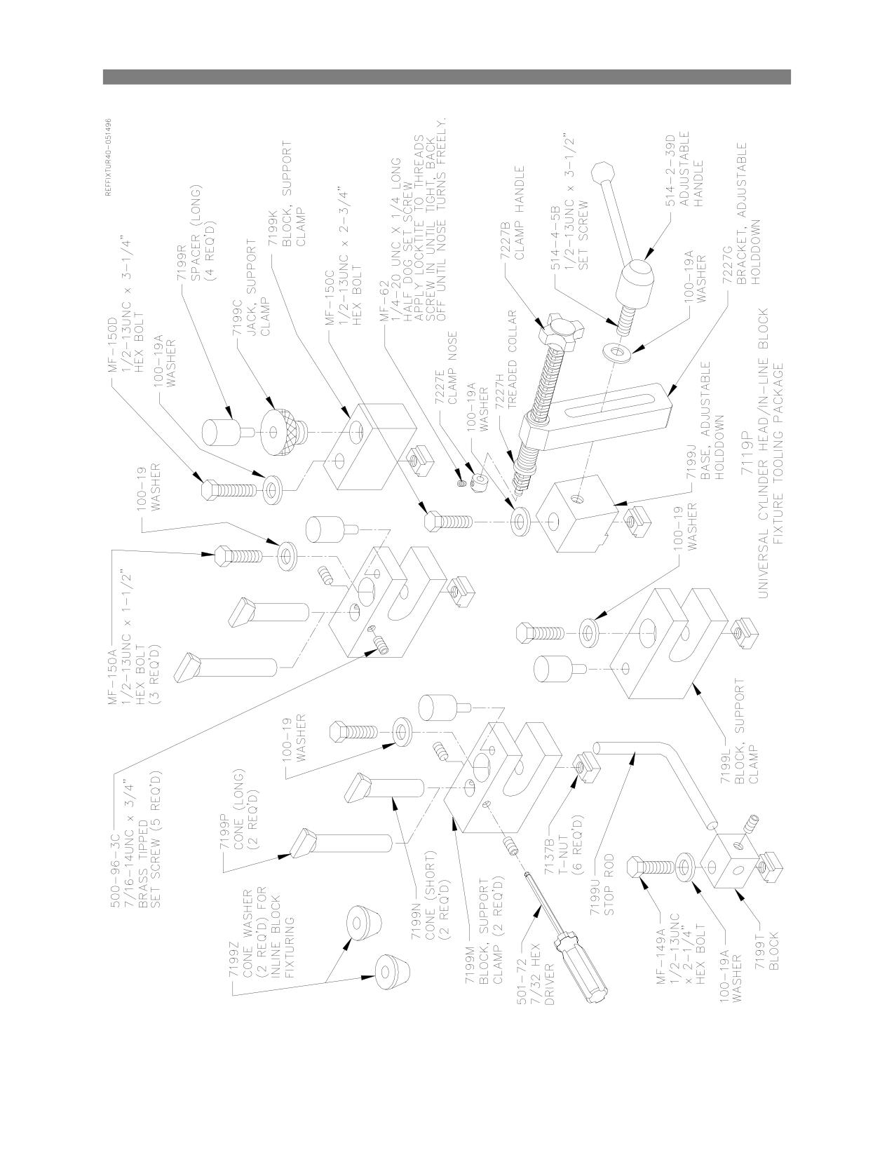
Universal Tooling Package 7119P:
Options
6-35
F65 Manual
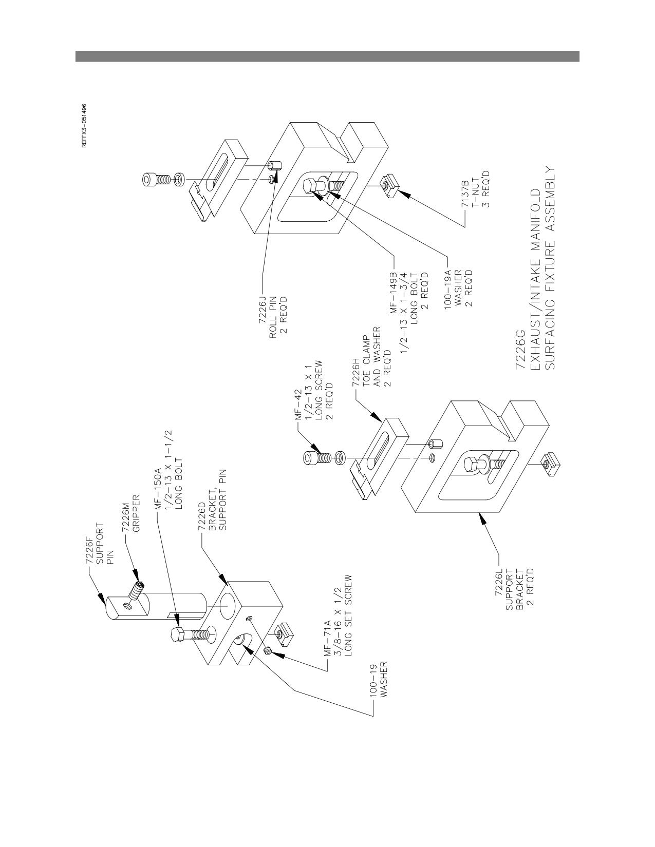
Exhaust/Intake Manifold Surfacing Fixture Assembly 7226G:
Options
6-36
F65 Manual
Exhaust/Intake Manifold Fixture:
Instructions
This fixture is designed to hold most exhaust manifolds and most intake manifolds from 90 degree V8
Engines.
Exhaust Manifolds
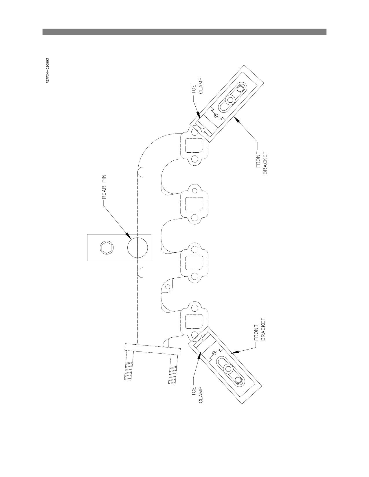
1) Most exhaust manifolds will be surfaced with the supports positioned approximately as shown on next
page. Occasionally it may be necessary to rearrange the support blocks to accommodate an unusual
manifold.
2) Place a manifold on the two front brackets. Adjust the rear pin to provide the best support. The best
place for the front brackets is under the machined area, for the manifold mounting bolts, at the
outside corners of the manifold. The rear pin should be approximately midway between the front
brackets on the rear of the part. The pin should support under the main body of the manifold.
3) Adjust the rear pin up and down to bring the manifold close to level.
4) Tighten the toe clamps evenly against the cast surface of the manifold (be sure the toe clamps are
not pushing on a machined surface). Tighten firmly, test for clamp tightness with a soft face mallet.
5) Level the manifold surface using the hand wheels and the dual axis level system of the table.
6) Make sure there are no obstructions in the way of the cutterhead you are using.
7) The manifold is ready to surface.
Options
6-37
F65 Manual
Typical Exhaust Manifold Set-up:
Options
6-38
F65 Manual
Intake Instructions:
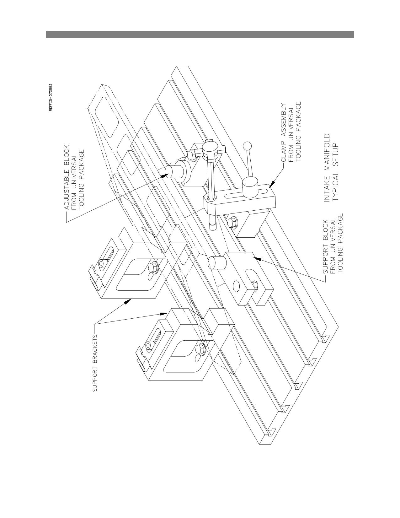
This fixture will require parts from the Rottler universal head tooling package.
1.
This fixture is designed primarily for the intake manifolds from 90 degree V8 engines.
2.
Start with the support blocks arranged as shown on the next page. Leave the hold down bolts
finger tight so that the block will slide easily.
3.
Place the manifold in the two rear support brackets so they fit flush and parallel on the intake
surface. Tighten the hold down bolts securely.
4.
Adjust the remaining two support blocks to give support to the manifold at the front. Slide the
clamp assembly over and position the clamp foot so it will push on a solid area of the manifold,
approximately centered.
5.
Tighten the clamp handle securely. Check to make sure the manifold did not move.
6.
Using a small precision level, level the exposed intake surface, in both directions, by tilting the
dual axis table as necessary.
7.
Using the left hand wheel only, rotate the table to level the lower surface of the manifold.
8.
This surface is ready to cut.
9.
After surfacing , rotate the table using the left hand wheel only, down to the center or lower
surface. Level this surface.
10.
This surface is ready to cut.
11.
Loosen the clamp screw and remove the manifold. Turn it around and reload with the fresh cut
surface in the rear support blocks. Level the intake manifold surface and cut.
12.
Using the left hand wheel, level the second lower surface and cut it.
Caution: At all stages of this process be sure there are no obstructions that might interfere with the
cutterhead.
Options
6-39
F65 Manual
Typical Intake Manifold Set-up:
Options
6-40
F65 Manual
Dual Axis Level Assembly 7125A:
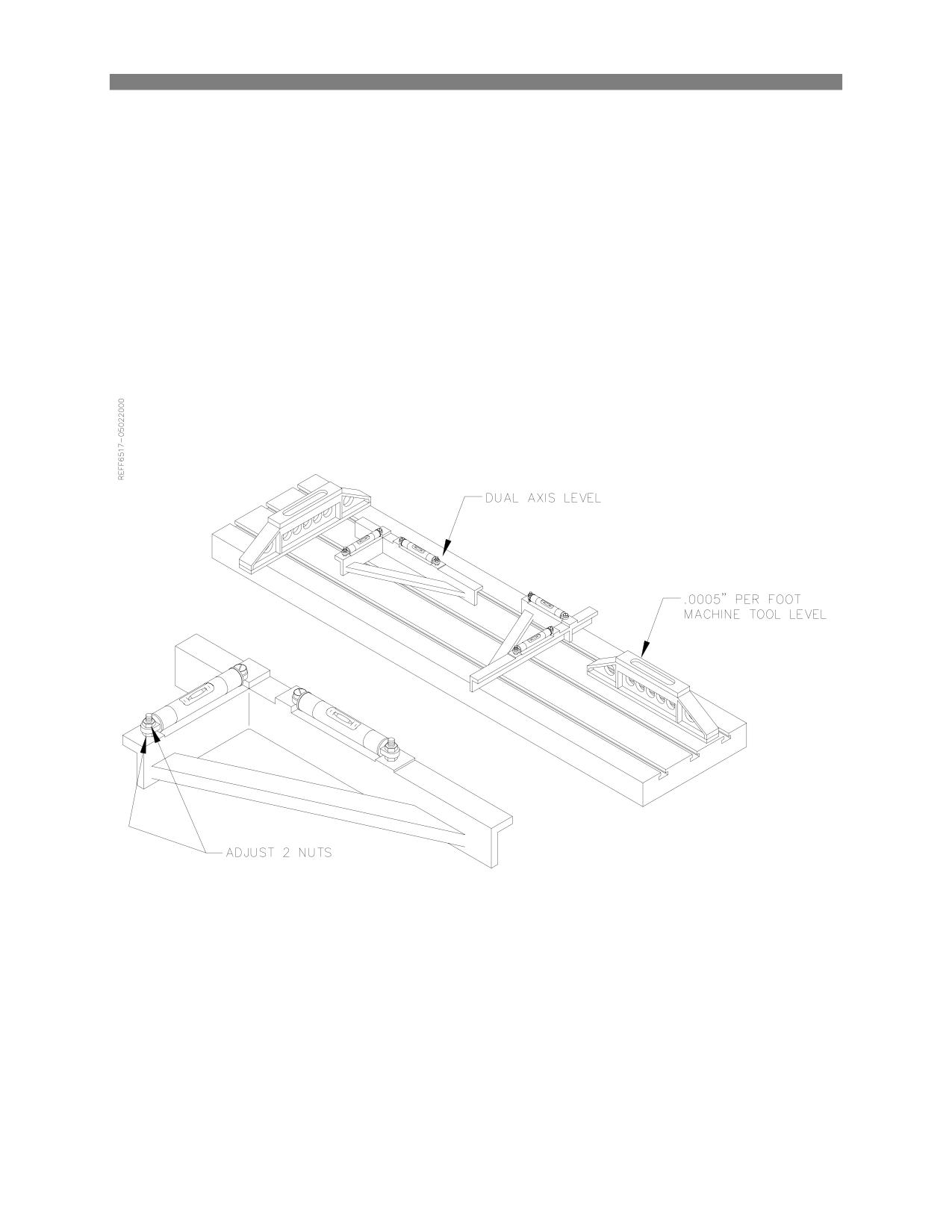
Method of leveling set up, and periodic verification of Rottler F-65 Machining Center.
1.
Level machine with a .0005/foot machine tool level so that the work surface is level within
.0005/foot in both axis.
2.
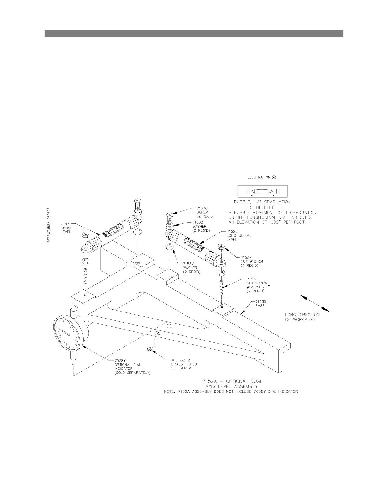
Now place dual axis level (7152A) on the work surface. It should read level in both vials, the vials
will need to be adjusted if they do not read level. Turn the level 90 degrees and check in this
direction also.
3.
The leveling check should be made frequently on a new machine since typical floor support
conditions take a while to permanently seat in. Then a wwekly re-check should be adequate,
unless you have a reason to doubt accuracy.
Options
6-41
F65 Manual
The following procedures are necessary to properly use the leveling table and dual axis level for single
cut milling of cylinder head decks.
1.
Place the cylinder head on the table and clamp into place approximately level.
2.
Place level on head surface and adjust the hand wheels so that cross level is centered and
longitudinal level bubble moves slightly left of center, approximately ¼ graduation (see illustration
A). The purpose of this is to assure clean up of the extreme left of the head.
3.
Now, in order to adjust for minimal stock removal, look at the flatness dial indicator (7038Y)
reading.
a) If the reading is at “0” or past “0” the surface is flat or convex. Accordingly, set the cutter
height dial at .002 to .003 past “0” and begin cut.
b) If the level dial is short of “0” that means the deck surface is concave and you will have to
remove more material at the beginning of the cut. In general, add about .003” on cutter depth
for every .002” the level dial is short of “0” on short heads. On long heads add .005” of cutter
depth for every .002” of indicator reading. It is important to finish with a single as much as
possible. Multiple cuts will result in more tool wear as well as considerably more time cost.
Options
6-42
F65 Manual
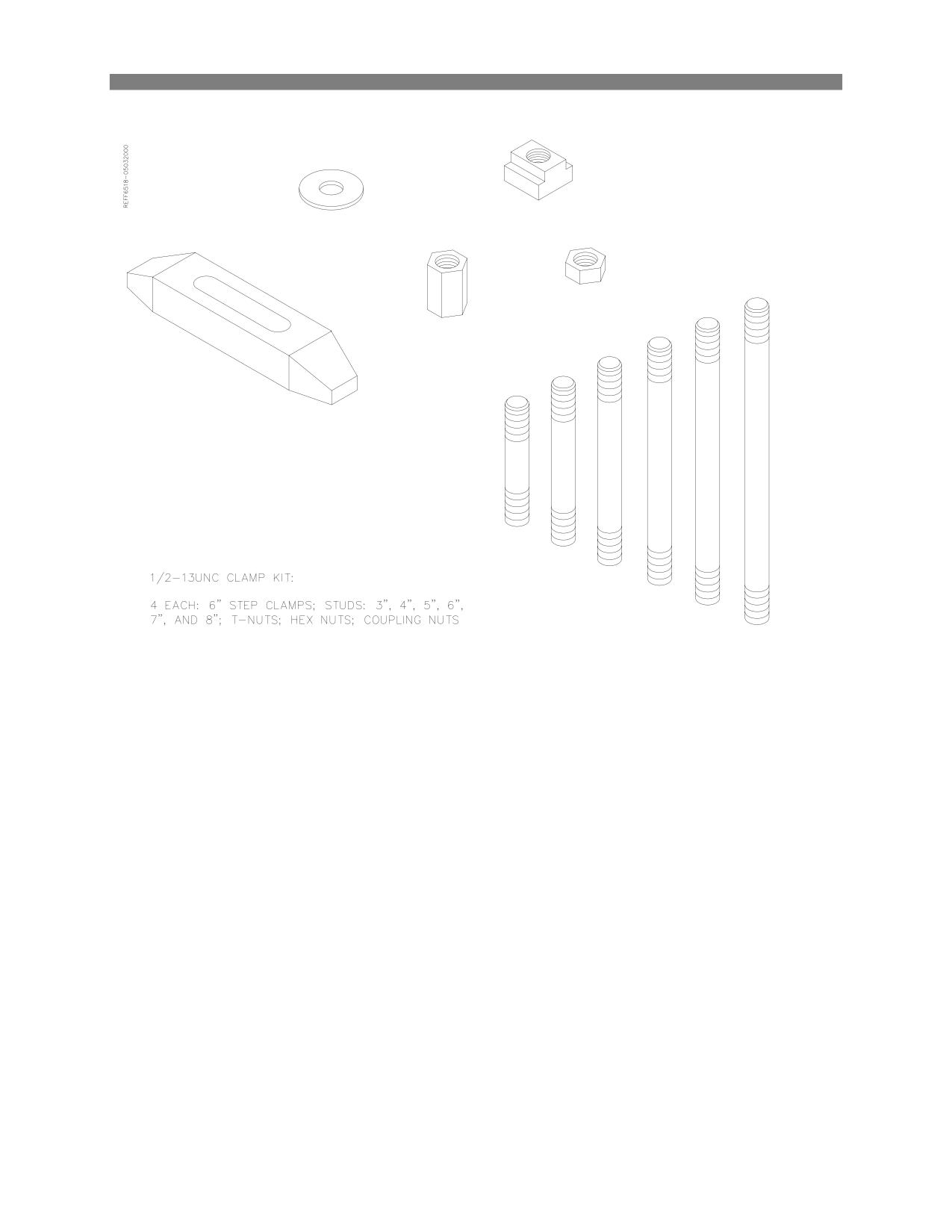
½” Clamp Kit:
650-3-37
Options
6-43
F65 Manual
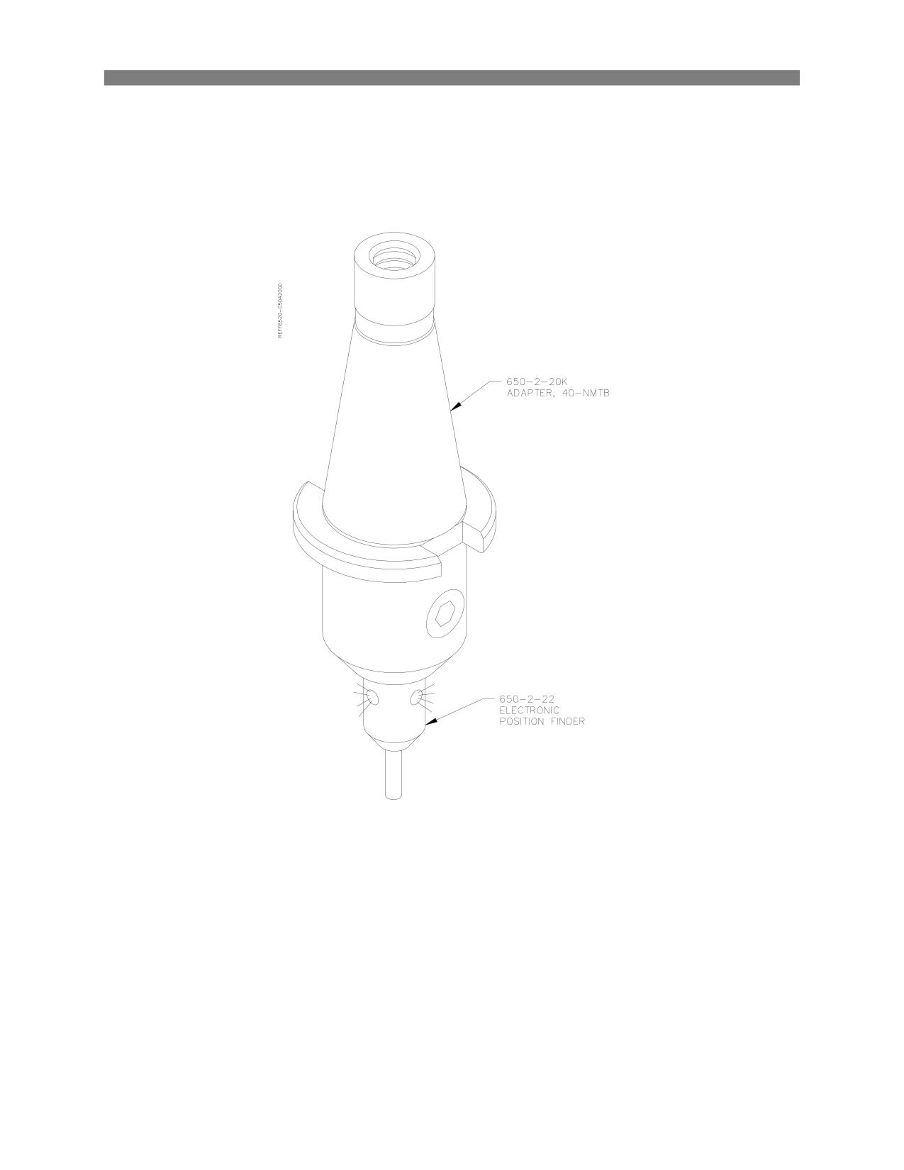
3 Dimensional Electronic Position Finder 502-9-9G:
Options
6-44
F65 Manual
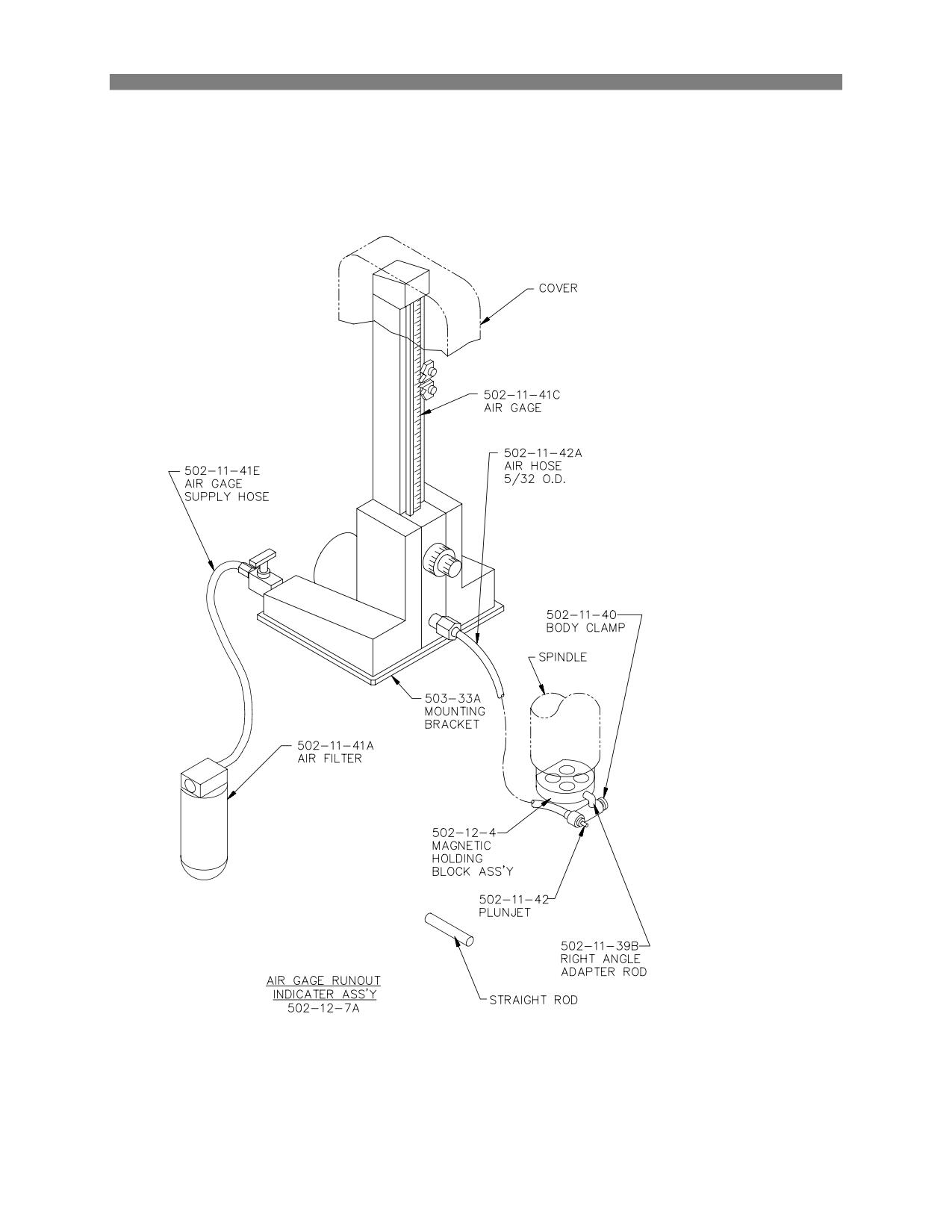
Remote run-Out indicating System 502-12-7A:
An optional remote indication air probe and gauge system is also available to check bore and face run-
out. The stationary indicator allows easier reading and can be used in lower bore extremities where the
mechanical dial indicator cannot be seen. The air probe can be used in a considerably smaller bore size
relative to the spindle diameter.
Options
6-45
F65 Manual
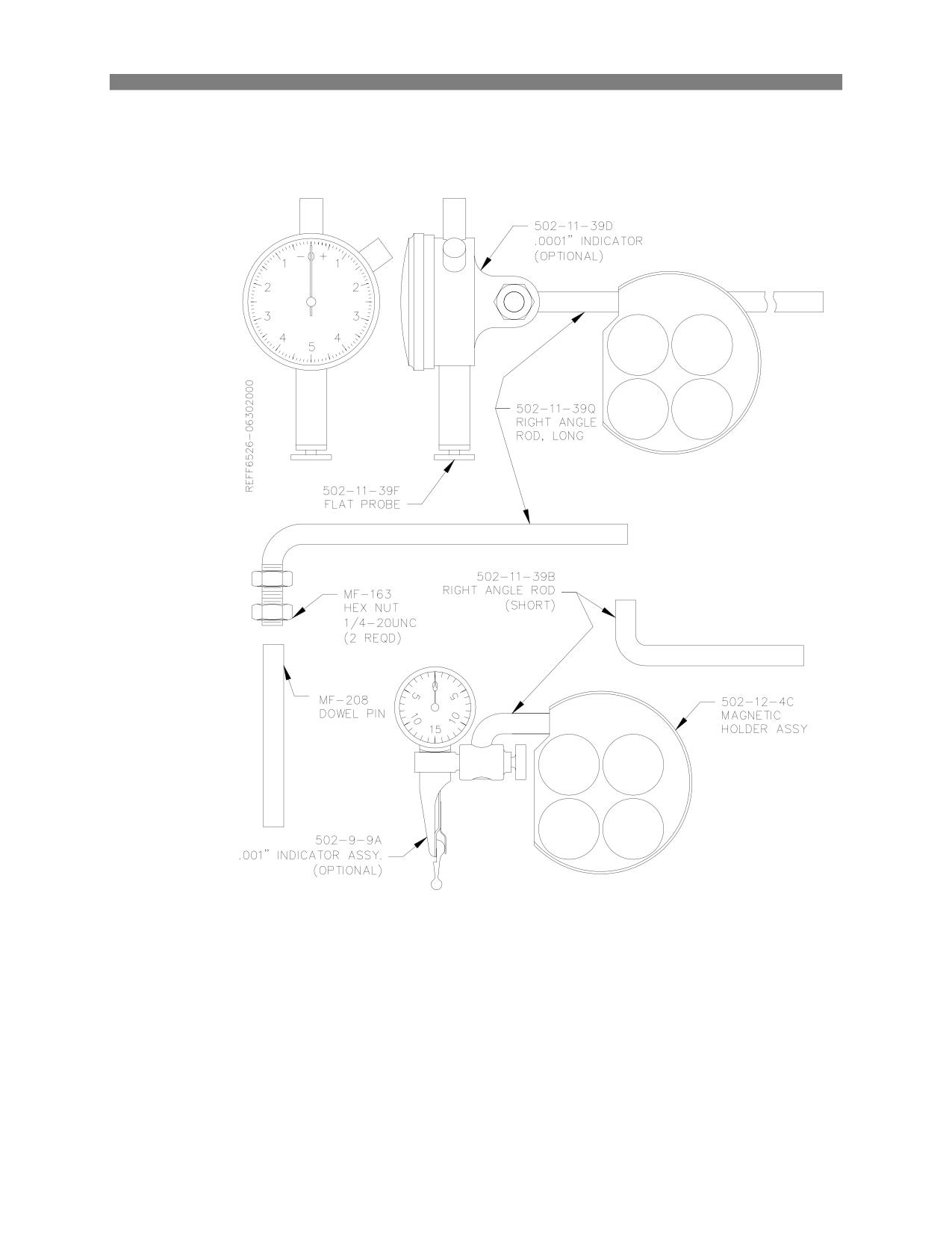
Magnetic Indicator Holder 502-12-4:
Options
6-46
F65 Manual
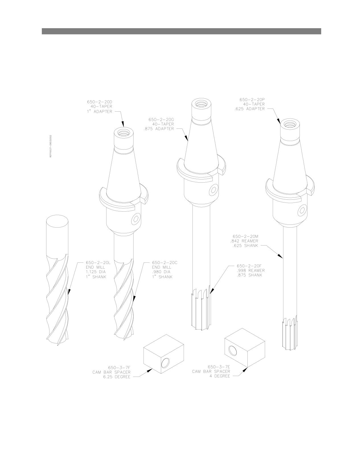
Lifter Bore Tooling Package 650-2-20:
Options
6-47
F65 Manual
Additional Lifter Bore Tooling:
650-2-20Q
End mill, Special .859" Dia. X 8 1/4" long-4 flute (7/8" shank)-(Ford)
650-2-20X
End mill, Special .890" Dia. X 8 1/4" long-4 flute (7/8" shank)-(Mopar)
650-2-20J
Expansion reamer, .875" Dia. X 10" long (3/4" Shank) (Ford)
650-2-20V
Expansion reamer, .9035/.904" Dia. X 10" long (3/4" Shank) (Mopar)
650-2-20Y
Expansion reamer. Special .993 dia. X 10-1/2" long (7/8" shank) (Mopar)
650-3-7G
Spacer, cam bar 3.5 degree Ford 289/302/351W
650-3-7H
Spacer, cam bar 4-degree Ford 429/400
650-3-7J
Spacer cam bar 48-degree Mopar small block (Race)
650-2-20R
Adaptor-1/2" NMTB 40 taper
650-2-20P
Adaptor-5/8" NMTB 40 taper
650-2-20K
Adaptor-3/4" NMTB 40 taper
650-2-20G
Adaptor-7/8" NMTB 40 taper
650-2-20D
Adaptor-1" NMTB 40 taper
650-2-20S
Adaptor-1 1/4" NMTB 40 taper
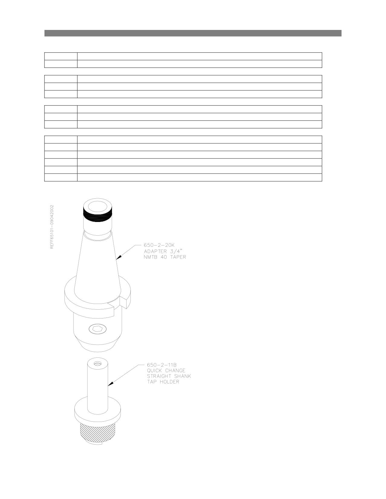
Quick Change Tap Holder Assembly 650-2-11J:
Options
6-48
F65 Manual
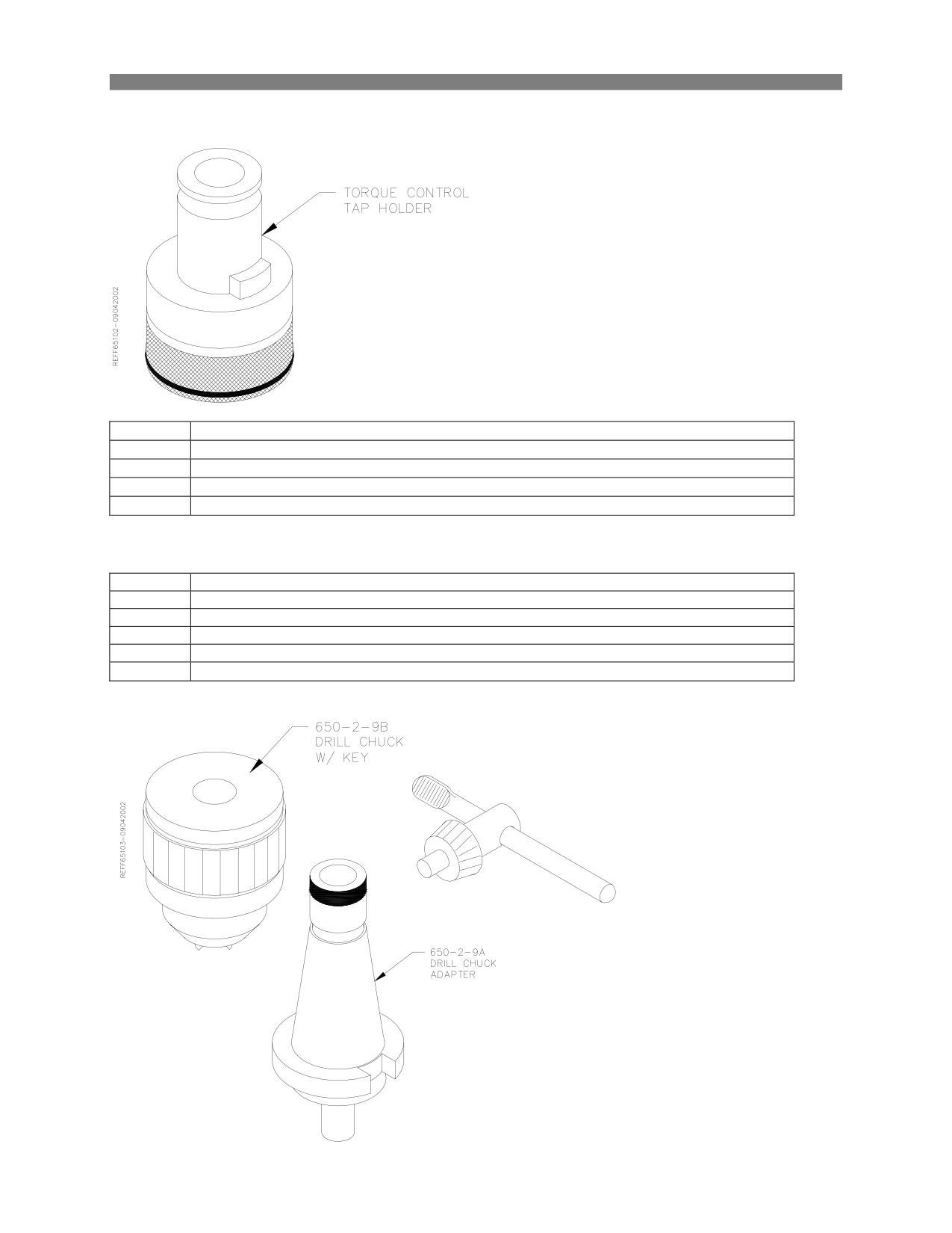
Torque Control Tap Holders:
Use with 650-2-11J Assembly
650-2-11C
Torque Control Tap Holder for 1/4" taps
650-2-11D
Torque Control Tap Holder for 5/16" taps
650-2-11E
Torque Control Tap Holder for 3/8" taps
650-2-11F
Torque Control Tap Holder for 7/16" taps
650-2-11G
Torque Control Tap Holder for 1/2" taps
Adapters NMTB 40 Taper:
650-2-20R
Adaptor-1/2" NMTB 40 taper
650-2-20P
Adaptor-5/8" NMTB 40 taper
650-2-20K
Adaptor-3/4" NMTB 40 taper
650-2-20G
Adaptor-7/8" NMTB 40 taper
650-2-20D
Adaptor-1" NMTB 40 taper
650-2-20S
Adaptor-1 1/4" NMTB 40 taper
Precision Drill Chuck Assembly 650-2-9:
Options
6-49
F65 Manual
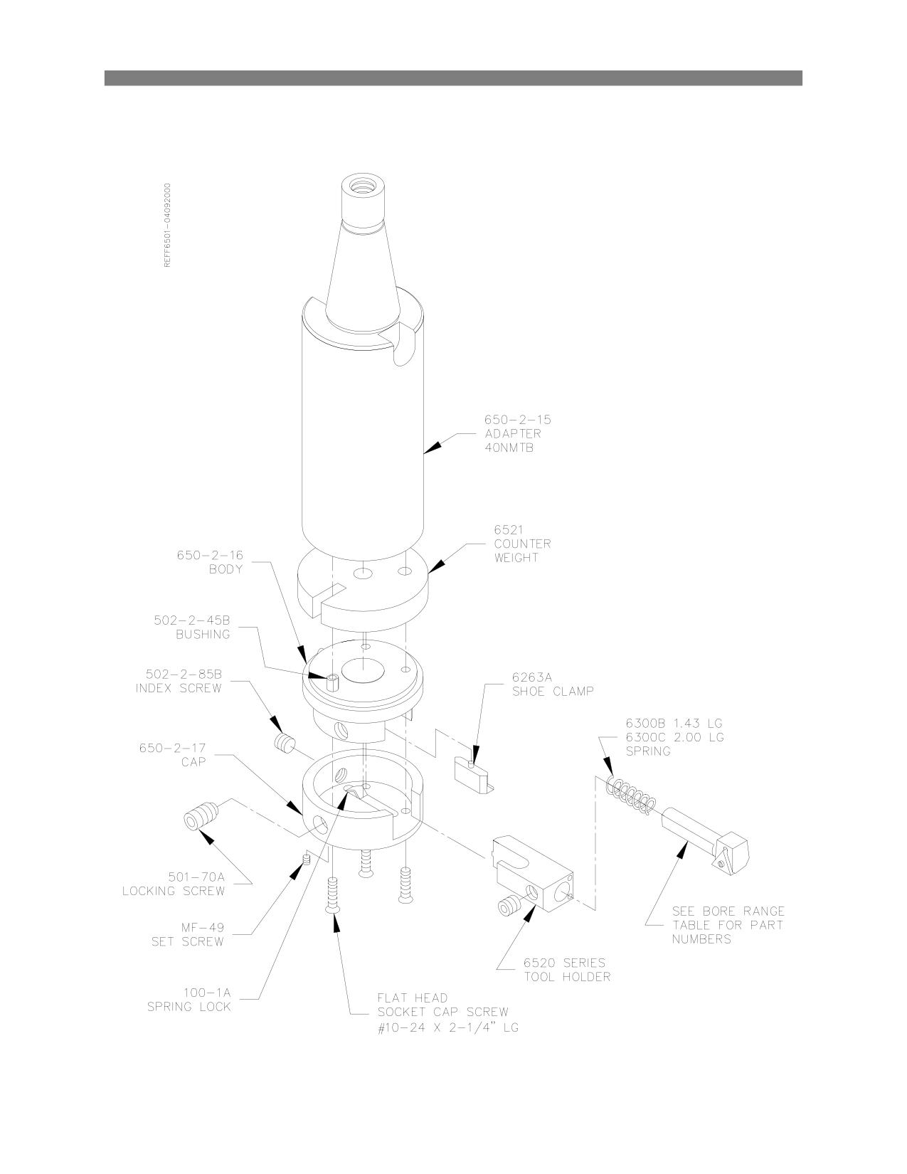
2.9” Cutterhead:
650-2-14 with Tooling
650-2-14A without Tooling
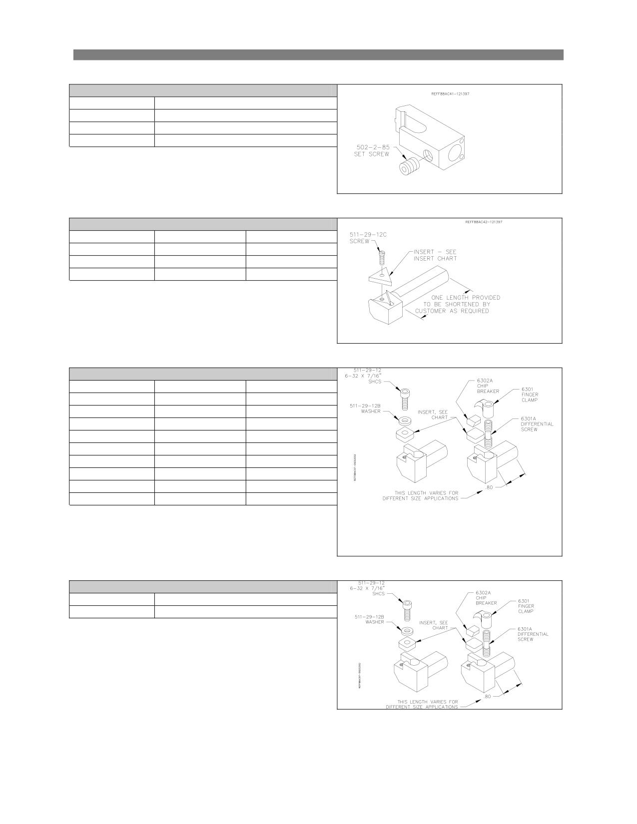
Options
6-50
F65 Manual
2.9” Cutterhead Standard Tooling:
6520 Series Tool Holders
Tool Holder
Length
6520H
2.25”
6520A
2.37”
6520B
2.62”
6598K Tool Bit when used with 6520 Holders
Tool Bit
Tool Holder
Bore Range
6598K
6520H
3.75” - 4.00”
6598K
6520A
4.00” - 4.50”
6598K
6520B
4.50” - 5.00”
Triangle insert positive rake
6260 SeriesTool Bit when used with 6520 Holders
Tool Bit
Tool Holder
Bore Range
6260K
6520H
3.75” - 4.00”
6260K
6520A
6260K
6520B
6260L
6520H
4.00” - 4.50”
6260L
6520A
6260L
6520B
6260M
6520H
6260M
6520A
6260M
6520B
4.50” - 5.00”
Square insert negative rake
6260 SeriesTool Bit when used with 6520 Holders
Tool Bit
Bore Range
6260W
3.78” - 5.24”
Square insert negative rake
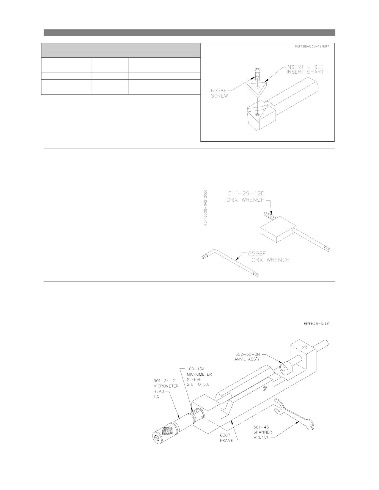
Options
6-51
F65 Manual
6547 Series Chamfering Tool Bits
when used with 6520 Holders
Chamfer
Tool Bit
Bore Range
Angle
6547F
30
3.10” - 5.00”
6547G
20
3.30” - 5.00”
6547M
15
3.45” - 5.00”
Triangle insert positive rake
511-29-12D Torx Wrench
6598F Torx Wrench
For use with Torx style screw in Triangle cartridges.
6307F Micrometer Assembly
2.9” - 5.0”
Options
6-52
F65 Manual
2.9” Cutterhead Optional Tooling:
6513 Series Grooving Tool Bits
when used with 6520 Holders
Groove
Tool Bit
Tool Holder
Bore Range
DIA.
6513J
.037”
6520H
3.55” - 3.95”
6513J
.037”
6520A
3.95” - 4.45”
6513J
.037”
6520B
4.45” - 4.85”
6513L
.039”
6520H
3.55” - 3.95”
6513L
.039”
6520A
3.95” - 4.45”
6513L
.039”
6520B
4.45” - 4.85”
6513N
.060”
6520H
3.55” - 3.95”
6513N
.060”
6520A
3.95” - 4.45”
6513N
.060”
6520B
4.45” - 4.85”
6513P
.085”
6520H
3.55” - 3.95”
6513P
.085”
6520A
3.95” - 4.45”
6513P
.085”
6520B
4.45” - 4.85”
Square insert negative rake
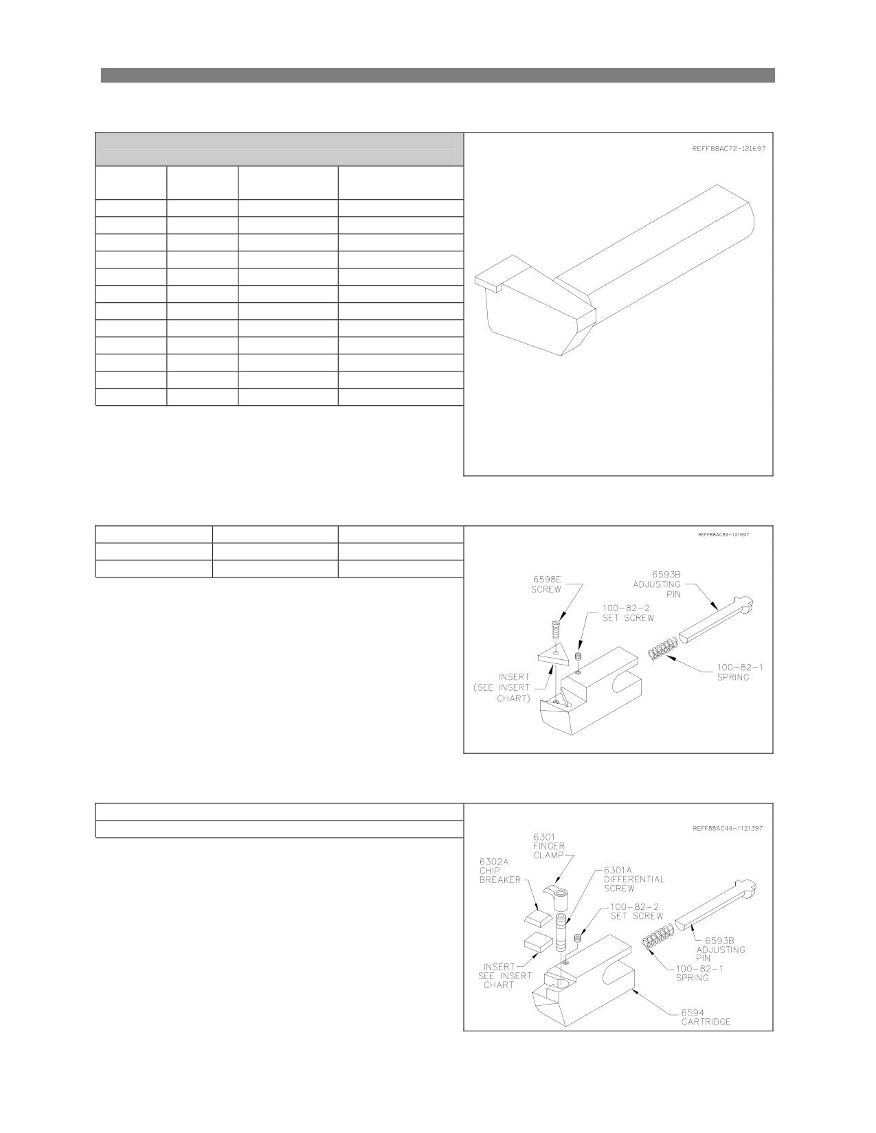
Cartridge Tool Holders:
Tool Holder
Length
Bore Range
6593C
2.03”
2.90” - 3.40”
6593D
2.25”
3.40” - 3.90”
Triangle insert positive rake
6594 Cartridge Tool Holder:
Bore Range
2.90” - 3.90”
Square insert negative rake
Options
6-53
F65 Manual
Boring Inserts:
Speeds and Feed Rates will vary from Cutter Head to Cutter Head when using the same insert due to the
different properties of each Cutter Head.
Boring Speeds and Feeds:
The Following insert feeds and speeds are designed to be used with the 650-2-14 Cutter Head Assembly.
Below is a description of the cutting inserts available from Rottler. The inserts have gone through
extensive performance testing. To take full advantage of the capabilities of your Rottler Machine, we
highly recommend Rottler tooling be used. This chart uses SFM or Surface Feet Per Minute as a speed
reference. To calculate SFM to RPM use the following formula.
RPM = SFM X 3.83
DIAMETER
Example:
SFM = 800
4.00” Bore
800 X 3.83 = 3064 Divide by the diameter 4.00 = 766 RPM
Insert
Part #
Description
Application
This is a 3/8” I.C. (inscribed
It is used for through boring when removing
circle) square insert with a
.010-.060 inches on the diameter. For best
501-29-6B
gold titanium coating.
tool life use 500 - 800 SFM. Use a feed rate
of .004 - .010 to obtain the typical surface
finish.
This is a 3/8” I.C. (inscribed
For best tool life use 800 - 1200 SFM. Use a
circle) square insert with a
feed rate of .006 - .012 to obtain the typical
501-29-6E
purple ceramic coating.
surface finish.
RT321
A 3/8” IC triangular insert
The ceramic coating gives excellent results for
with a dark purple ceramic
both heavy sleeve cutting and finishing of cast
coating and 1/64” cutting
iron and nodular cast iron when a square step
radius.
is required. The 1/64” radius should be used
when machining to a step where the mating
part requires a smaller radius to eliminate an
interference problem. If you are machining a
long bore where the spindle must be extended
towards the limits of its travel or if a long stub
bar is being used, the
1/64” radius will
minimize the possibility of chatter. A feed rate
of .002 - .005 should be used to obtain a
typical surface finish. When machining large
counter bores typically found in Cummins or
Cat Blocks, a feed rate of .002 - .004/rev.
should be used. When cutting gray cast iron
use a speed in the 800 - 1200 SFM area for
best productivity and tool life. When cutting
nodular cast iron the speed should be in the
200 - 400 SFM area. Nodular cast iron is
found most often in high performance engine
blocks or sleeves.
RT322
This is the same insert as
This larger radius insert will give a smoother
RT321, except it has a 1/32”
finish when sleeve cutting to allow easier
radius.
sleeve fitting and closer metal to metal contact
for heat transfer. The 1/32” radius is stronger
Options
6-54
F65 Manual
than the 1/64 radius of the RT321. The RT322
should always be used for sleeve cuts unless
the finish part requires the smaller radius for
clearance or you are cutting a long bore. The
larger radius creates more tool pressure than
the small tool radius. The increased tool
pressure will create chatter in the finish. A
feed rate of .002 - .010 should be used to
obtain a typical surface finish. When
machining large counter bores typically found
in Cummins or Cat Blocks, a feed rate of .002
- .004/rev. should be used. When cutting gray
cast iron use a speed in the 800 - 1200 SFM
area for best productivity and tool life. When
cutting nodular cast iron the speed should be
in the 200 - 400 SFM area. Nodular cast iron
is found most often in high performance
engine blocks or sleeves.
RT211
A 3/8” IC triangular insert
The ceramic coating gives excellent results for
with a dark purple ceramic
both heavy sleeve cutting and finishing of cast
coating and 1/64” cutting
iron and nodular cast iron when a square step
radius.
is required. The 1/64” radius should be used
when machining to a step where the mating
part requires a smaller radius to eliminate an
interference problem. If you are machining a
long bore where the spindle must be extended
towards the limits of its travel or if a long stub
bar is being used, the 1/64” radius will
minimize the possibility of chatter. A feed rate
of .002 - .005 should be used to obtain a
typical surface finish. When machining large
counter bores typically found in Cummins or
Cat Blocks, a feed rate of .002 - .004/rev.
should be used. When cutting gray cast iron
use a speed in the 800 - 1200 SFM area for
best productivity and tool life. When cutting
nodular cast iron the speed should be in the
200 - 400 SFM area. Nodular cast iron is
found most often in high performance engine
blocks or sleeves.
RT221
This is the same insert as
This larger radius insert will give a smoother
RT321, except it has a 1/32”
finish when sleeve cutting to allow easier
radius.
sleeve fitting and closer metal to metal contact
for heat transfer. The 1/32” radius is stronger
than the 1/64 radius of the RT321. The RT322
should always be used for sleeve cuts unless
the finish part requires the smaller radius for
clearance or you are cutting a long bore. The
larger radius creates more tool pressure than
the small tool radius. The increased tool
pressure will create chatter in the finish. A
feed rate of .002 - .010 should be used to
obtain a typical surface finish. When
machining large counter bores typically found
in Cummins or Cat Blocks, a feed rate of .002
- .004/rev. should be used. When cutting gray
cast iron use a speed in the 800 - 1200 SFM
area for best productivity and tool life. When
cutting nodular cast iron the speed should be
Options
6-55
F65 Manual
in the 200 - 400 SFM area. Nodular cast iron
is found most often in high performance
engine blocks or sleeves.
6301E
This is a square 3/8” I.C.,
These inserts are intended for use on high
1/32” Radius, Solid, CBN-
speed F-84/85 boring machines up to 2000
Cubic Boron Nitride - Insert
RPM. A feed rate of .010”
-
.014” per
revolution. They have exceptional life when
boring .040” or less at a high rate of speed.
6301J
This is a square 3/8” I.C.,
These inserts are intended for use on high
1/16” Radius, Solid, CBN-
speed F-84/85 boring machines up to 2000
Cubic Boron Nitride - Insert
RPM. A feed rate of .010”
-
.014” per
revolution. They have exceptional life when
boring .040” or less at a high rate of speed.
The large radius will increase the tool
pressure and could cause chatter in the bore
when used near the limits of the cutterhead.
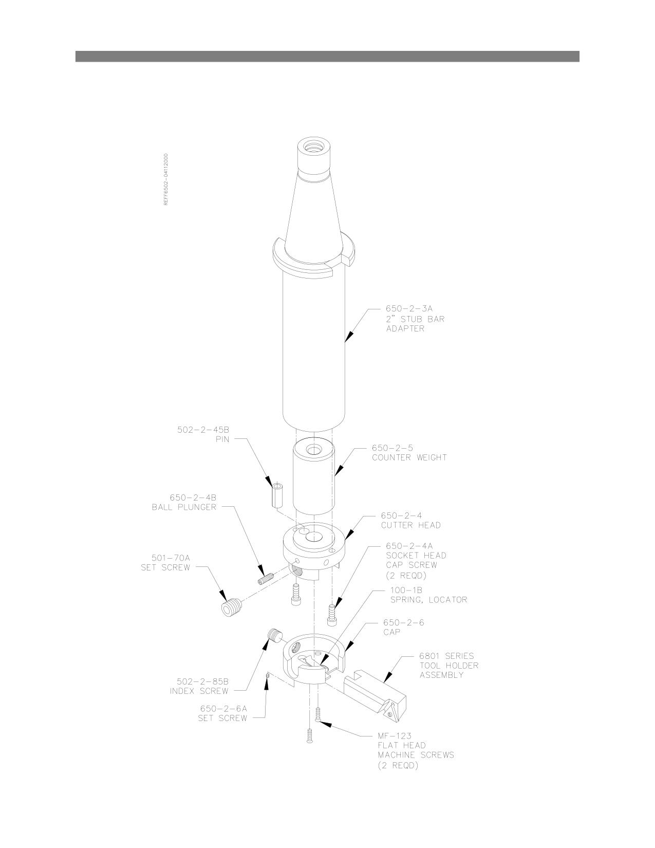
Options
6-56
F65 Manual
2.0” Cutterhead:
650-2-1 w/o Tooling
650-2-1A w/ Tooling
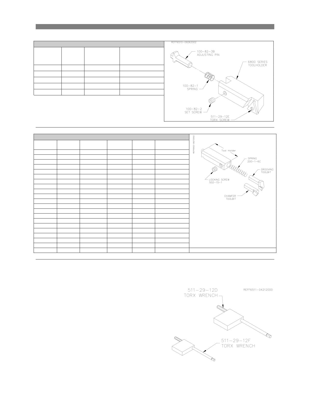
Options
6-57
F65 Manual
2.0” Cutterhead Standard Tooling:
6801 Series Tool Holders
Tool
Assembly
Holder
Length
Bore Range
Part #
Part #
6801B
6800B
1.54”
2.0” - 2.4”
6801C
6800C
1.75”
2.4” - 2.8”
6801D
6800D
1.95”
2.8” - 3.2”
6801E
6800E
2.15”
3.2” - 3.6”
6801F
6800F
2.35”
3.6” - 4.0”
Triangle insert positive rake
199 Series Tool Holders
Tool
Holder
Tool Bit
Tool bit
Degree
Bore Range
Holder
Length
Grooving
Chamfer
or Width
199-96
1.25”
501-33B
15 Deg
2.15” - 2.80”
“
“
501-33C
20 Deg
“
“
“
501-33D
30 Deg
“
“
“
501-31-3
.037”
“
“
“
501-31-1
.048”
“
199-89
1.50”
501-33B
15 Deg
2.80” - 3.45”
“
“
501-33C
20 Deg
“
“
“
501-33D
30 Deg
“
“
“
501-31-3
.037”
“
“
“
501-31-1
.048”
“
199-90
1.75”
501-33B
15 Deg
3.45” - 4.10”
“
“
501-33C
20 Deg
“
“
“
501-33D
30 Deg
“
“
“
501-31-3
.037”
“
“
“
501-31-1
.048”
“
199-94
2.25”
501-33B
15 Deg
4.10” - 4.75”
“
“
501-33C
20 Deg
“
“
“
501-33D
30 Deg
“
“
“
501-31-3
.037”
“
“
“
501-31-1
.048”
“
511-29-12D Torx Wrench
511-29-12F Torx Wrench
For use with Torx style screw in Triangle cartridges.
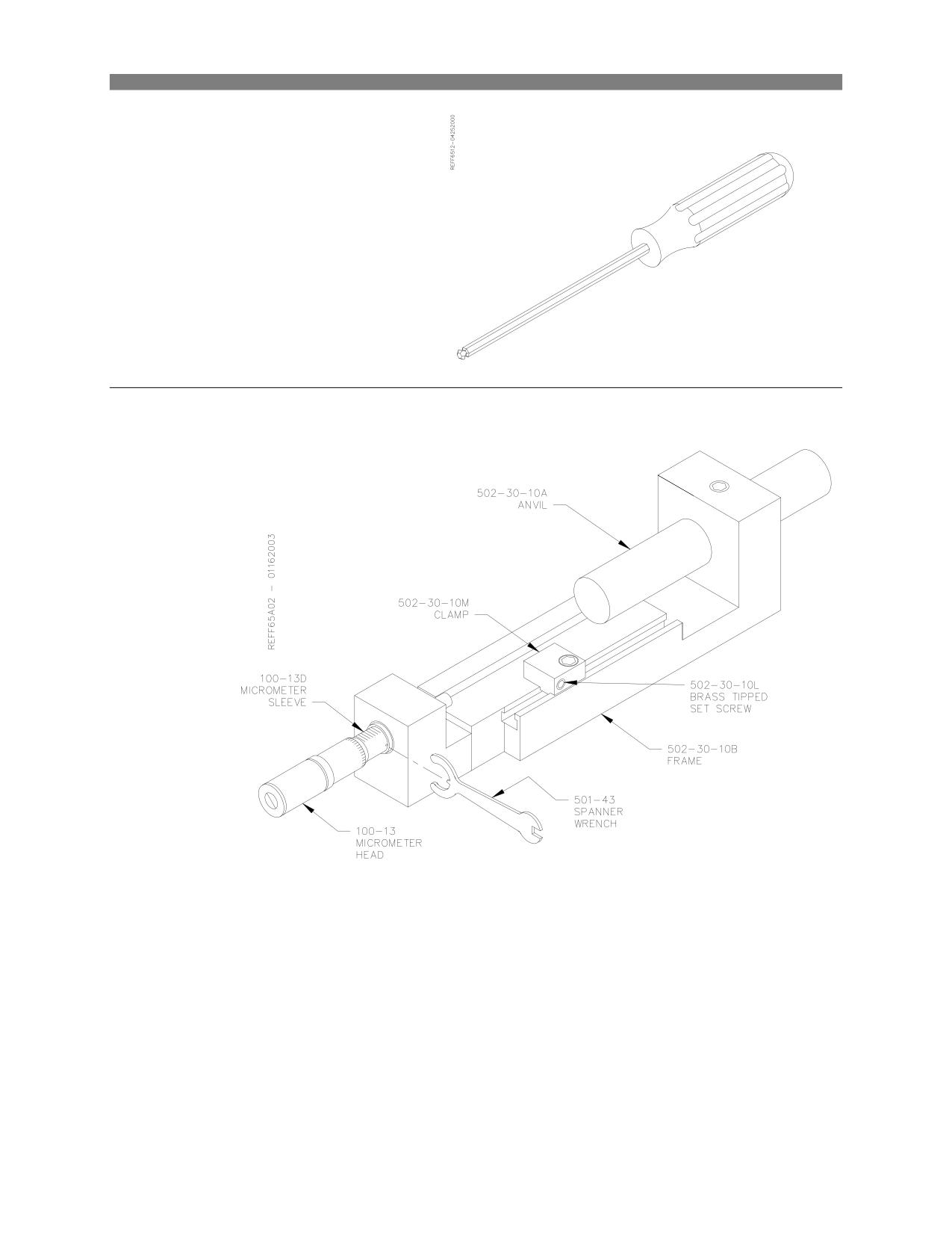
Options
6-58
F65 Manual
501-72J Hex Driver
900-2-11 Micrometer Assembly
2.0” - 4.0”
Boring Inserts:
Speeds and Feed Rates will vary from Cutter Head to Cutter Head when using the same insert due to the
different properties of each Cutter Head.
Boring Speeds and Feeds:
The Following insert feeds and speeds are designed to be used with the 650-2-1 Cutter Head Assembly.
Below is a description of the cutting inserts available from Rottler. The inserts have gone through
extensive performance testing. To take full advantage of the capabilities of your Rottler Machine, we
highly recommend Rottler tooling be used. This chart uses SFM or Surface Feet Per Minute as a speed
reference. To calculate SFM to RPM use the following formula.
RPM = SFM X 3.83
DIAMETER
Options
6-59
F65 Manual
Example:
SFM = 800
4.00” Bore
800 X 3.83 = 3064 Divide by the diameter 4.00 = 766 RPM
Insert
Part #
Description
Application
RT321
A 3/8” IC triangular insert
The ceramic coating gives excellent results for
with a dark purple ceramic
both heavy sleeve cutting and finishing of cast
coating and 1/64” cutting
iron and nodular cast iron when a square step
radius.
is required. The 1/64” radius should be used
when machining to a step where the mating
part requires a smaller radius to eliminate an
interference problem. If you are machining a
long bore where the spindle must be extended
towards the limits of its travel or if a long stub
bar is being used, the
1/64” radius will
minimize the possibility of chatter. A feed rate
of .002 - .005 should be used to obtain a
typical surface finish. When machining large
counter bores typically found in Cummins or
Cat Blocks, a feed rate of .002 - .004/rev.
should be used. When cutting gray cast iron
use a speed in the 400 - 600 SFM area for
best productivity and tool life. When cutting
nodular cast iron the speed should be in the
200 - 400 SFM area. Nodular cast iron is
found most often in high performance engine
blocks or sleeves.
RT322
This is the same insert as
This larger radius insert will give a smoother
RT321, except it has a 1/32”
finish when sleeve cutting to allow easier
radius.
sleeve fitting and closer metal to metal contact
for heat transfer. The 1/32” radius is stronger
than the 1/64 radius of the RT321. The RT322
should always be used for sleeve cuts unless
the finish part requires the smaller radius for
clearance or you are cutting a long bore. The
larger radius creates more tool pressure than
the small tool radius. The increased tool
pressure will create chatter in the finish. A
feed rate of .002 - .010 should be used to
obtain a typical surface finish. When
machining large counter bores typically found
in Cummins or Cat Blocks, a feed rate of .002
- .004/rev. should be used. When cutting gray
cast iron use a speed in the 400 - 600 SFM
area for best productivity and tool life. When
cutting nodular cast iron the speed should be
in the 200 - 400 SFM area. Nodular cast iron
is found most often in high performance
engine blocks or sleeves.
RT211
A 3/8” IC triangular insert
The ceramic coating gives excellent results for
with a dark purple ceramic
both heavy sleeve cutting and finishing of cast
coating and 1/64” cutting
iron and nodular cast iron when a square step
radius.
is required. The 1/64” radius should be used
when machining to a step where the mating
part requires a smaller radius to eliminate an
interference problem. If you are machining a
Options
6-60
F65 Manual
long bore where the spindle must be extended
towards the limits of its travel or if a long stub
bar is being used, the 1/64” radius will
minimize the possibility of chatter. A feed rate
of .002 - .005 should be used to obtain a
typical surface finish. When machining large
counter bores typically found in Cummins or
Cat Blocks, a feed rate of .002 - .004/rev.
should be used. When cutting gray cast iron
use a speed in the 400 - 600 SFM area for
best productivity and tool life. When cutting
nodular cast iron the speed should be in the
200 - 400 SFM area. Nodular cast iron is
found most often in high performance engine
blocks or sleeves.
RT221
This is the same insert as
This larger radius insert will give a smoother
RT321, except it has a 1/32”
finish when sleeve cutting to allow easier
radius.
sleeve fitting and closer metal to metal contact
for heat transfer. The 1/32” radius is stronger
than the 1/64 radius of the RT321. The RT322
should always be used for sleeve cuts unless
the finish part requires the smaller radius for
clearance or you are cutting a long bore. The
larger radius creates more tool pressure than
the small tool radius. The increased tool
pressure will create chatter in the finish. A
feed rate of .002 - .010 should be used to
obtain a typical surface finish. When
machining large counter bores typically found
in Cummins or Cat Blocks, a feed rate of .002
- .004/rev. should be used. When cutting gray
cast iron use a speed in the 400 - 600 SFM
area for best productivity and tool life. When
cutting nodular cast iron the speed should be
in the 200 - 400 SFM area. Nodular cast iron
is found most often in high performance
engine blocks or sleeves.
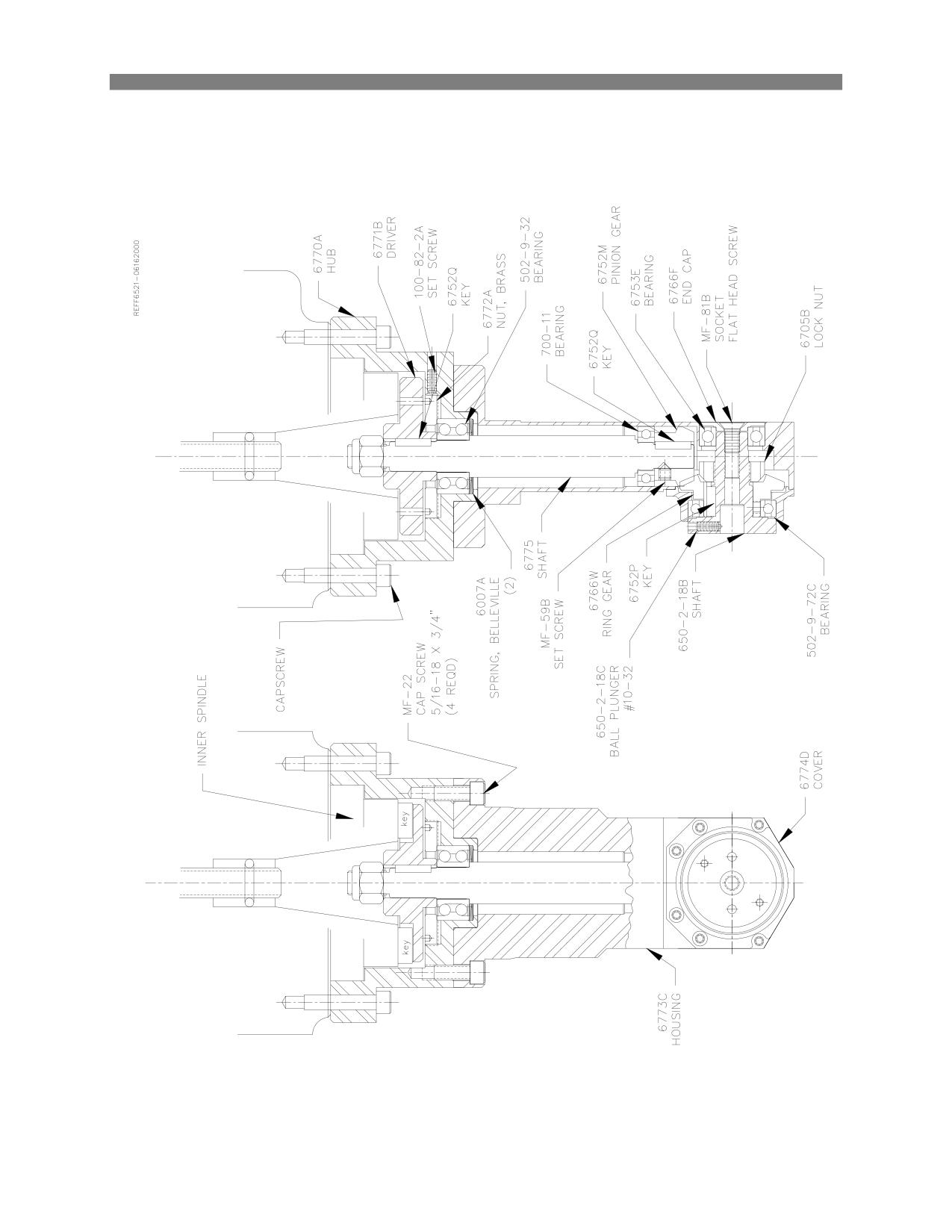
Options
6-61
F65 Manual
Right Angle Drive:
6733A w/o Tooling
650-2-19A w/ Tooling
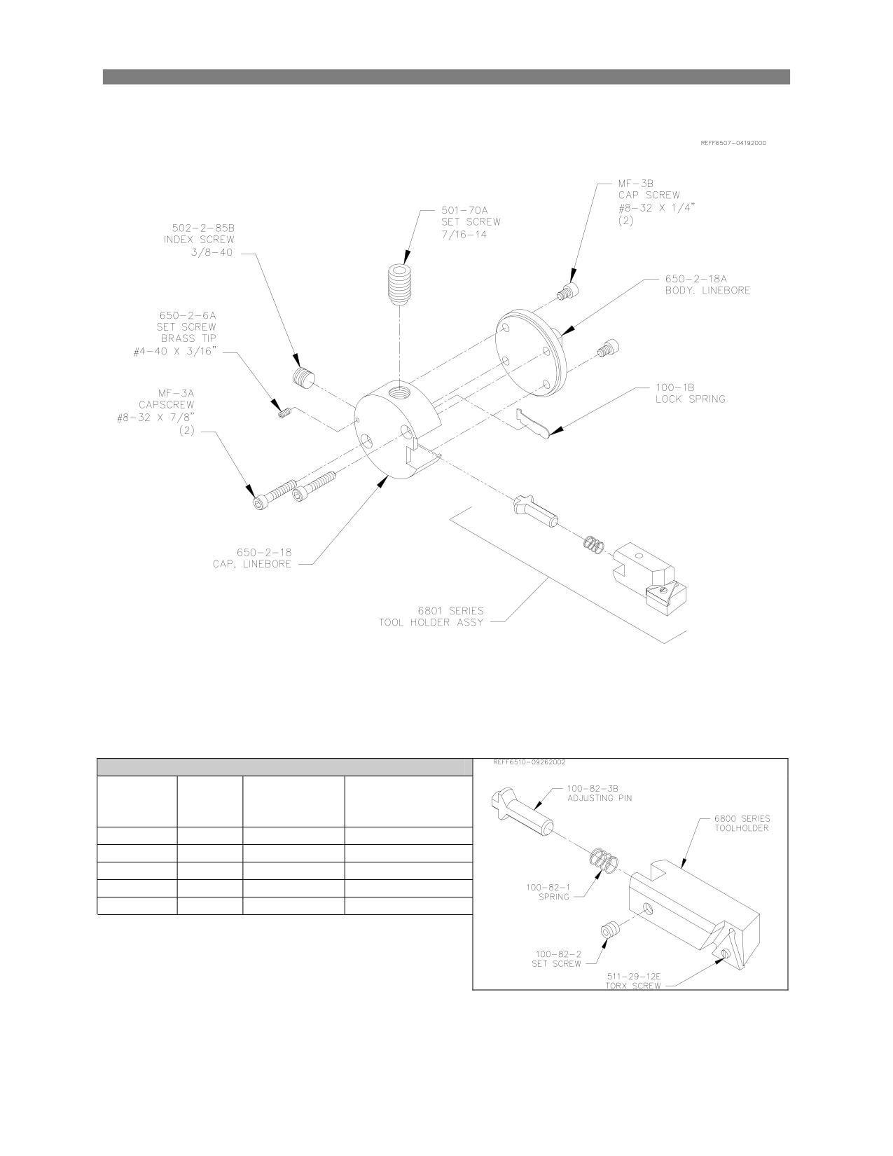
Options
6-62
F65 Manual
Right Angle Drive Tooling:
650-2-19 Line Bore Cutterhead:
6801 Series Tool Holders
Tool
Assembly
Holder
Length
Bore Range
Part #
Part #
6801B
6800B
1.54”
2.0” - 2.4”
6801C
6800C
1.75”
2.4” - 2.8”
6801D
6800D
1.95”
2.8” - 3.2”
6801E
6800E
2.15”
3.2” - 3.6”
6801F
6800F
2.35”
3.6” - 4.0”
Triangle insert positive rake
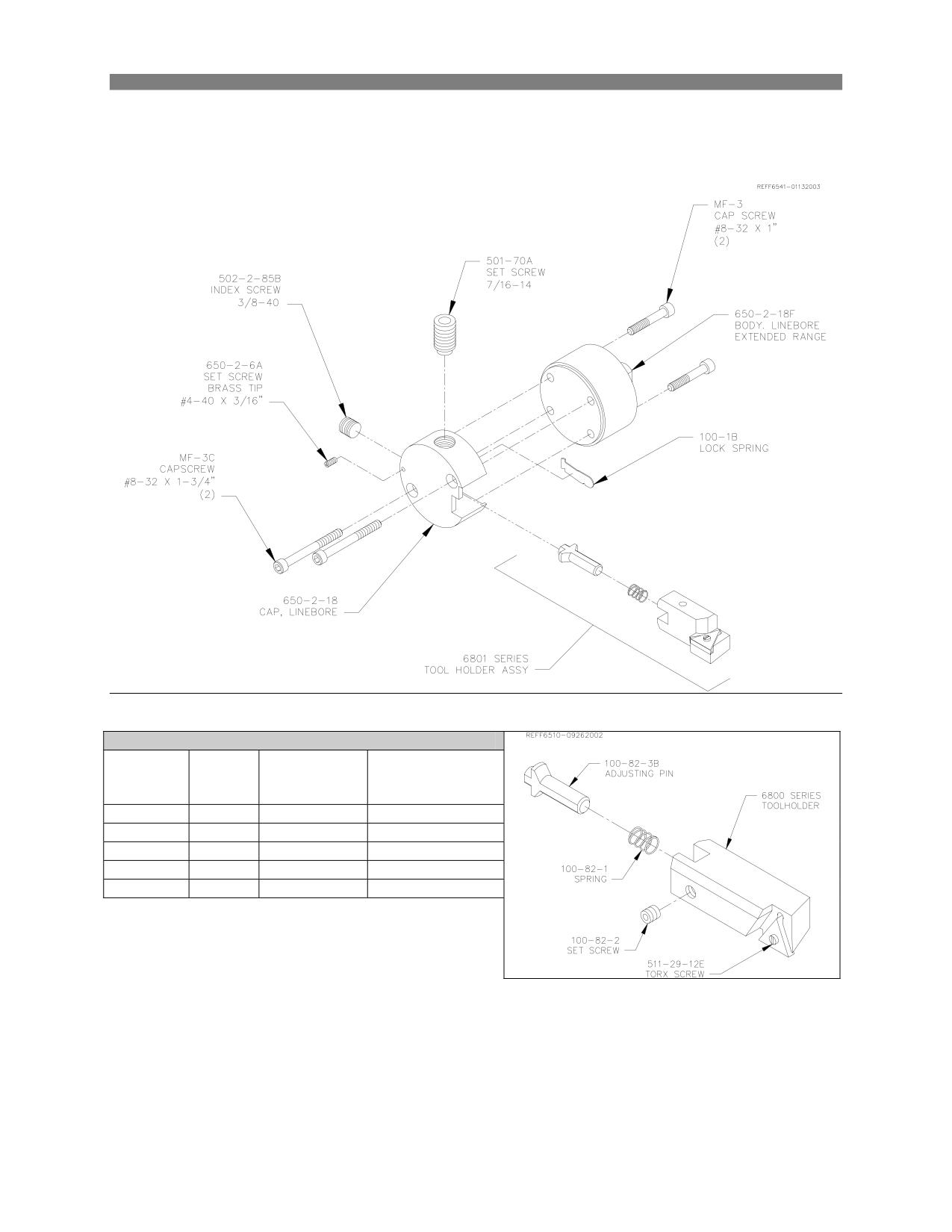
Options
6-63
F65 Manual
Right Angle Drive Tooling:
650-2-19B Extended Range Line Bore Cutterhead w/ Tooling:
650-2-19C Extended Range Line Bore Cutterhead w/o Tooling:
6801 Series Tool Holders
Tool
Assembly
Holder
Length
Bore Range
Part #
Part #
6801B
6800B
1.54”
2.0” - 2.4”
6801C
6800C
1.75”
2.4” - 2.8”
6801D
6800D
1.95”
2.8” - 3.2”
6801E
6800E
2.15”
3.2” - 3.6”
6801F
6800F
2.35”
3.6” - 4.0”
Triangle insert positive rake
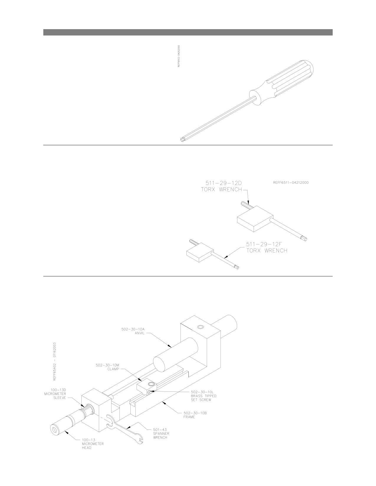
Options
6-64
F65 Manual
Hex Driver 3/16” 501-72J
Torx Wrench 511-29-12D
Torx Wrench 511-29-12F
Micrometer Assembly 900-2-11
2.0” - 4.0”
Options
6-65
F65 Manual
Boring Inserts:
Speeds and Feed Rates will vary from Cutter Head to Cutter Head when using the same insert due to the
different properties of each Cutter Head.
Boring Speeds and Feeds:
The Following insert feeds and speeds are designed to be used with the 650-2-19 and 19B Cutter Head
Assemblies.
Below is a description of the cutting inserts available from Rottler. The inserts have gone through
extensive performance testing. To take full advantage of the capabilities of your Rottler Machine, we
highly recommend Rottler tooling be used. This chart uses SFM or Surface Feet Per Minute as a speed
reference. To calculate SFM to RPM use the following formula.
RPM = SFM X 3.83
DIAMETER
Example:
SFM = 800
4.00” Bore
800 X 3.83 = 3064 Divide by the diameter 4.00 = 766 RPM
Insert
Part #
Description
Application
RT321
A 3/8” IC triangular insert
The ceramic coating gives excellent results for
with a dark purple ceramic
both heavy sleeve cutting and finishing of cast
coating and 1/64” cutting
iron and nodular cast iron. The 1/64” will
radius.
minimize the possibility of chatter on a line
bore. A feed rate of .002 - .003 should be
used to obtain a typical surface finish. A
speed of 200 to 400 SFM should be used for
best results.
RT322
This is the same insert as
This larger radius insert will give a smoother
RT321, except it has a 1/32”
finish but increase the possibility of chatter. A
radius.
feed rate of .002 - .003 should be used to
obtain a typical surface finish. A speed of 200
to 400 SFM should be used for best results.
RT211
A 3/8” IC triangular insert
The ceramic coating gives excellent results for
with a dark purple ceramic
both heavy sleeve cutting and finishing of cast
coating and 1/64” cutting
iron and nodular cast iron. The 1/64” will
radius.
minimize the possibility of chatter on a line
bore. A feed rate of .002 - .003 should be
used to obtain a typical surface finish. A
speed of 200 to 400 SFM should be used for
best results.
RT221
This is the same insert as
This larger radius insert will give a smoother
RT321, except it has a 1/32”
finish but increase the possibility of chatter. A
radius.
feed rate of .002 - .003 should be used to
obtain a typical surface finish. A speed of 200
to 400 SFM should be used for best results.
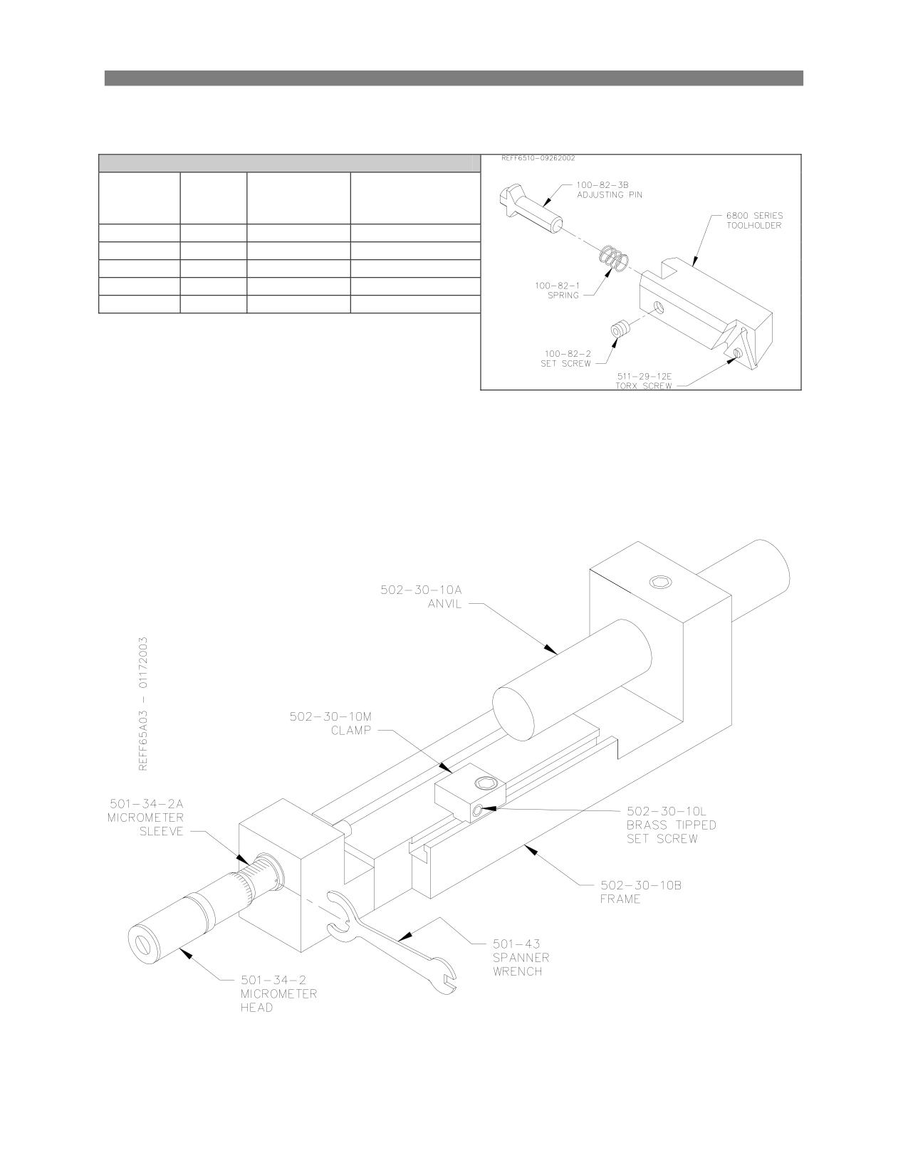
Options
6-66
F65 Manual
Optional Main Line Bore Tooling:
4” to 6”
(must use micrometer 900-2-5)
6801 Series Tool Holders
Tool
Assembly
Holder
Length
Bore Range
Part #
Part #
6801G
6800G
2.55”
4.0” - 4.4”
6801H
6800H
2.75”
4.4” - 4.8”
6801J
6800J
2.95”
4.8” - 5.2”
6801K
6800K
3.15”
5.2” - 5.6”
6801L
6800L
3.35”
5.6” - 6.0”
Triangle insert positive rake
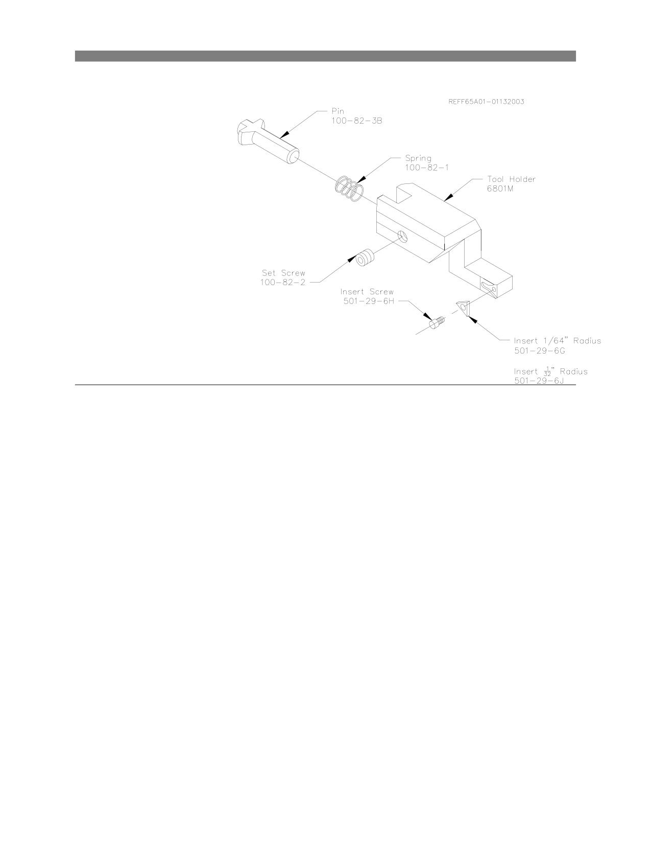
Options
6-67
F65 Manual
Thrust Facing Tool Holder;
6801M
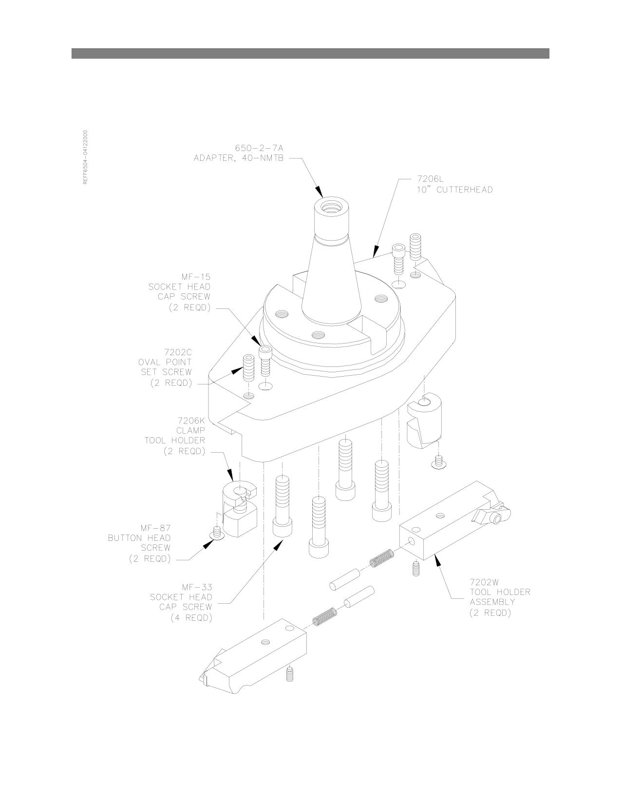
Options
6-68
F65 Manual
10” Surfacing Head w/ Tooling:
650-2-8B
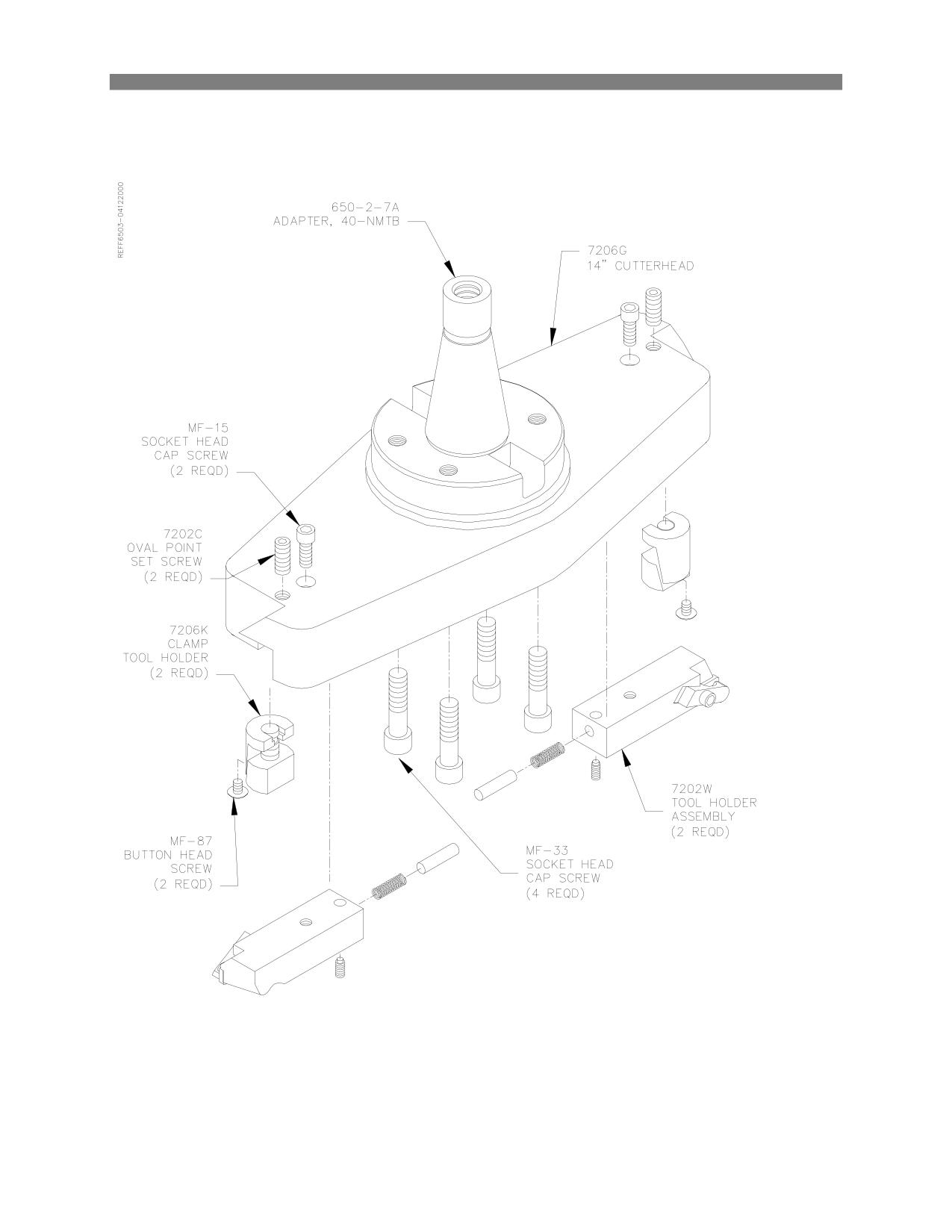
Options
6-69
F65 Manual
14” Surfacing Head w/ Tooling:
650-2-8C
Options
6-70
F65 Manual
Surfacing Inserts:
Surfacing Speeds and Feeds:
Below is a description of the cutting inserts available from Rottler. The inserts have gone through
extensive performance testing. To take full advantage of the capabilities of your Rottler Machine, we
highly recommend Rottler tooling be used.
Insert
Part #
Description
Application
An excellent, long life insert for surfacing cast
iron heads and blocks -round shape gives
A round 3/8” IC, double
6303B
many cutting edges on each side of insert.
sided, CBN Insert.
When using a 14” cutterhead (SF, F65, F80)
speeds range from 900-1200 RPM.
For use on aluminum only - heads and blocks
without liners. This insert has a thin layer of
PCD applied to a carbide disk. The diamond
appears to be a shiny black wafer. The
A round 3/8” IC, single
6303M
hardness of the diamond resists the abrasive
sided, PCD Insert.
nature of the silica in aluminum heads and
blocks. RPM speeds with a 14” cutter range
from 900-2000 RPM.
This is a very economical, general purpose
insert for surfacing aluminum. It is advisable to
use this insert for rough cutting to remove
welding or contaminants before. A PCD insert
A round, 3/8” IC, single
6303K
should be used for the final cut to give the
sided, coated carbide Insert.
super fine finish required for MLS (multi layer
steel) head gaskets. RPM speeds with a 14”
cutterhead range from 600-1000RPM.
For use on aluminum blocks with iron liners
and aluminum heads with steel pre-
combustion
chambers.
When
cutting
aluminum heads with pre-combustion
6303S
A round 3/8” IC, single
chambers it is best to use Rottler
sided, CBN Insert.
Manufacturing’s spray mist coolant system.
RPM speeds with a 14” cutter range from 650-
750 RPM.
For use on cast iron heads with steel pre-
6303R
A round 3/8” IC, single
combustion chambers. RPM speed with a 14”
sided, CBN Insert.
cutter range from 600-700 RPM.
This carbide insert is normally used for high
speed boring. It works well as an economical
This is a 3/8” IC square
insert for rough surfacing or heavy stock
501-29-6E
carbide insert with a purple
removal of cast iron. A CBN insert should be
ceramic coating.
used for the final finish cut.
The 1/16” radius of this insert will produce a
more accurate (flatter) finish than a round
A square 3/8” IC, 1/16”
insert typically used for surfacing. This insert
6301J
Radius, double sided, CBN
is often used on F80-Series machines when
Insert.
surfacing large diesel blocks which are high in
nickel.
The square surfacing insert is
intended for F80 applications where it may
Options
6-71
F65 Manual
encounter heavier cuts and greater interrupted
cuts. When using an 18” cutter speeds range
from 600-800 RPM, and with a 14” cutter
speeds range from 900-1200 RPM.
For use on aluminum only - heads and blocks
without liners. This insert has a thin layer of
PCD applied to the top of a carbide disk. The
diamond appears to be a shiny black wafer.
The hardness of the diamond resists the
abrasive nature of the silica in aluminum
A round 1/2” IC, single
heads and blocks. RPM speeds with a 14”
6303P
sided, PCD Insert.
cutter range from
1000-2000 RPM. This
insert gives the maximum productivity when
cutting aluminum. Requires the purchase of
1/2” negative rake tool holders. The standard
Rottler 3/8” IC tool holders will not hold this
insert.
An excellent insert for machining cast iron
heads and blocks. Round shape gives many
cutting edges on each side of insert. Requires
A round 1/2” IC double
6303Q
the purchase of
1/2” negative rake tool
sided, CBN Insert.
holders. The standard Rottler 3/8” IC tool
holders will not hold this insert.
General Information:
Rottler CBN and PCD Inserts are laser marked with our part number on one side. On single sided inserts,
the part number is on the back side of the insert.
Rottler surfacing insert toolholders are designated IC (inscribed circle) which means they can hold square
and round inserts with the same IC, for example, a 3/8” IC round and 3/8” IC square insert will fit into the
standard 3/8” IC Rottler toolholders.
Rottler SF, F65 and F80 Series machines are supplied standard with Rottler 3/8” IC toolholders fitted to
our surfacing heads. Optional 1/2” tool holders are interchangeable with 3/8” toolholders.
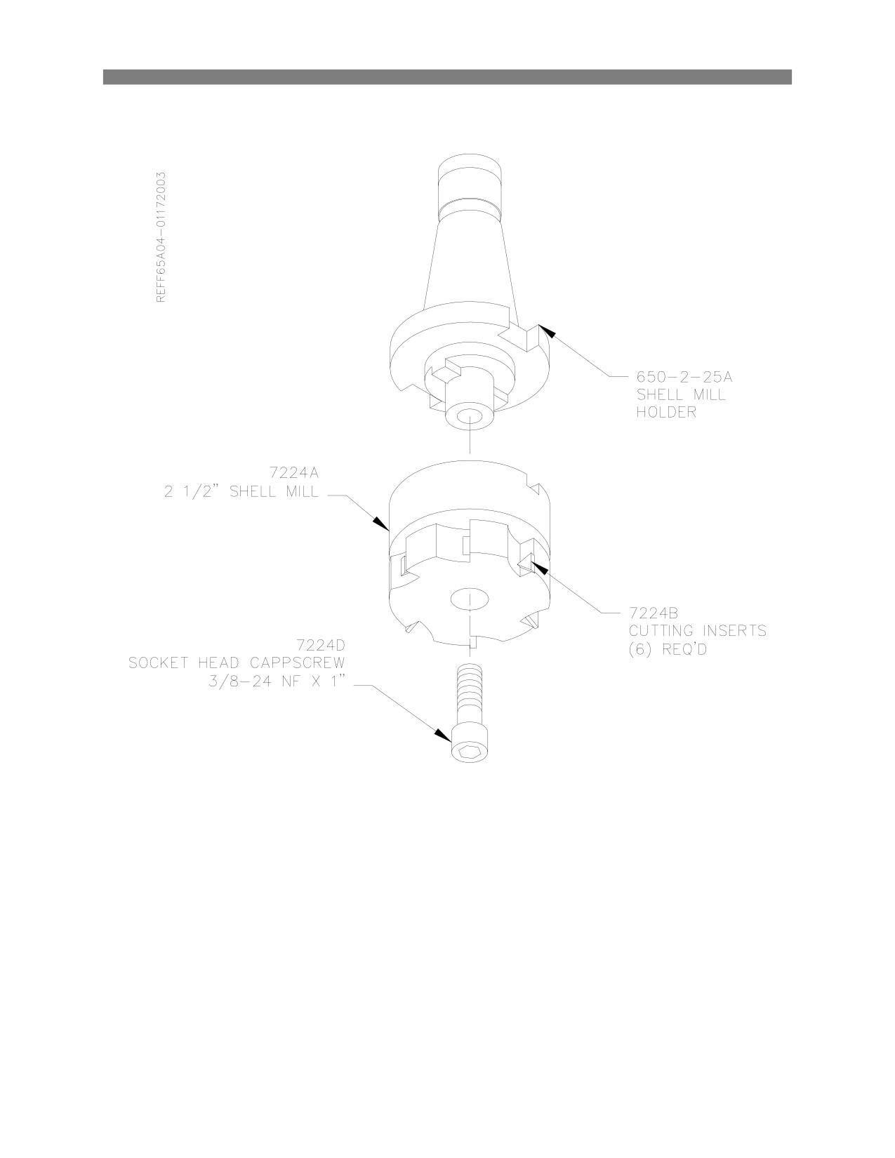
Options
6-72
F65 Manual
2 ½” Shell Mill Assembly w/ Tooling:
650-2-25
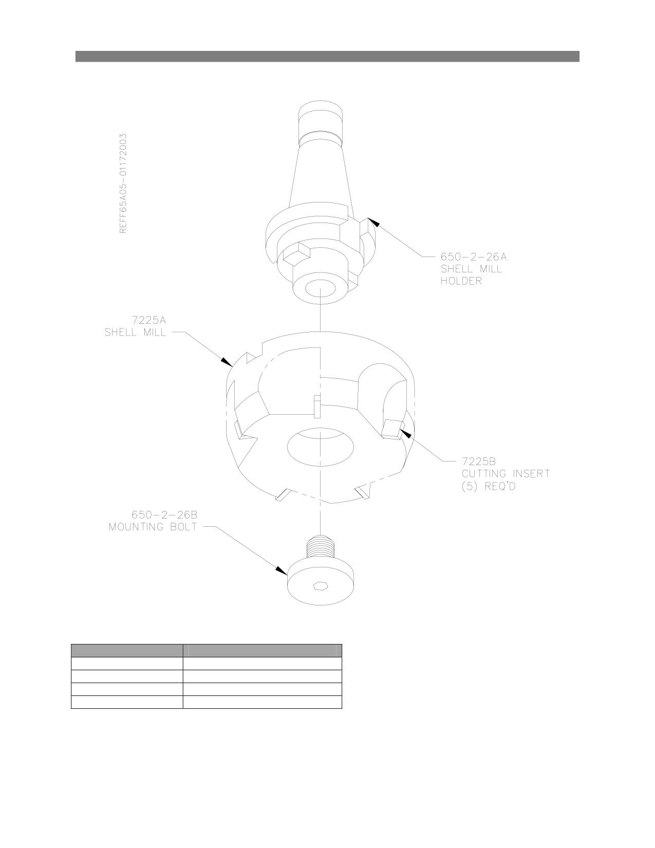
Options
6-73
F65 Manual
4” Shell Mill Assembly w/ Tooling:
650-2-26
Complete Listing of NMTB 40 Taper Shell Mill Arbors:
Part #
Width of Shell Mill Bore
6502-25A
¾”
650-2-20T
1”
650-2-26A
1 ¼”
650-2-20U
1 ½”
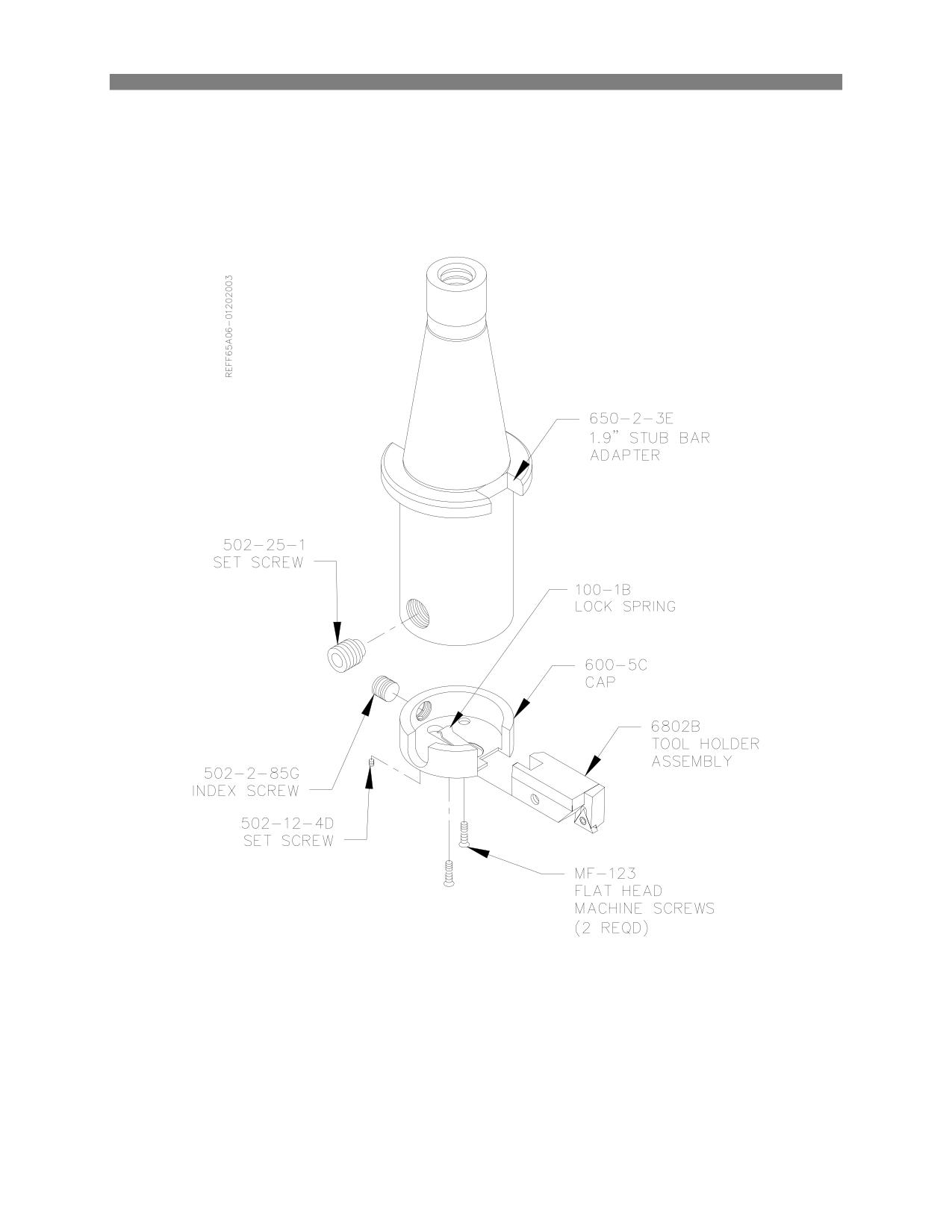
Options
6-74
F65 Manual
Cam Line Boring Tooling Package:
650-3-43A:
Requires 650-3-30 Block End Truing Fixture, 650-3-1 Performance Fixture, 6773A Right Angle Drive
Assembly.
1.9” Cutterhead:
650-2-3F w/ Tooling:
650-2-3G w/o Tooling:
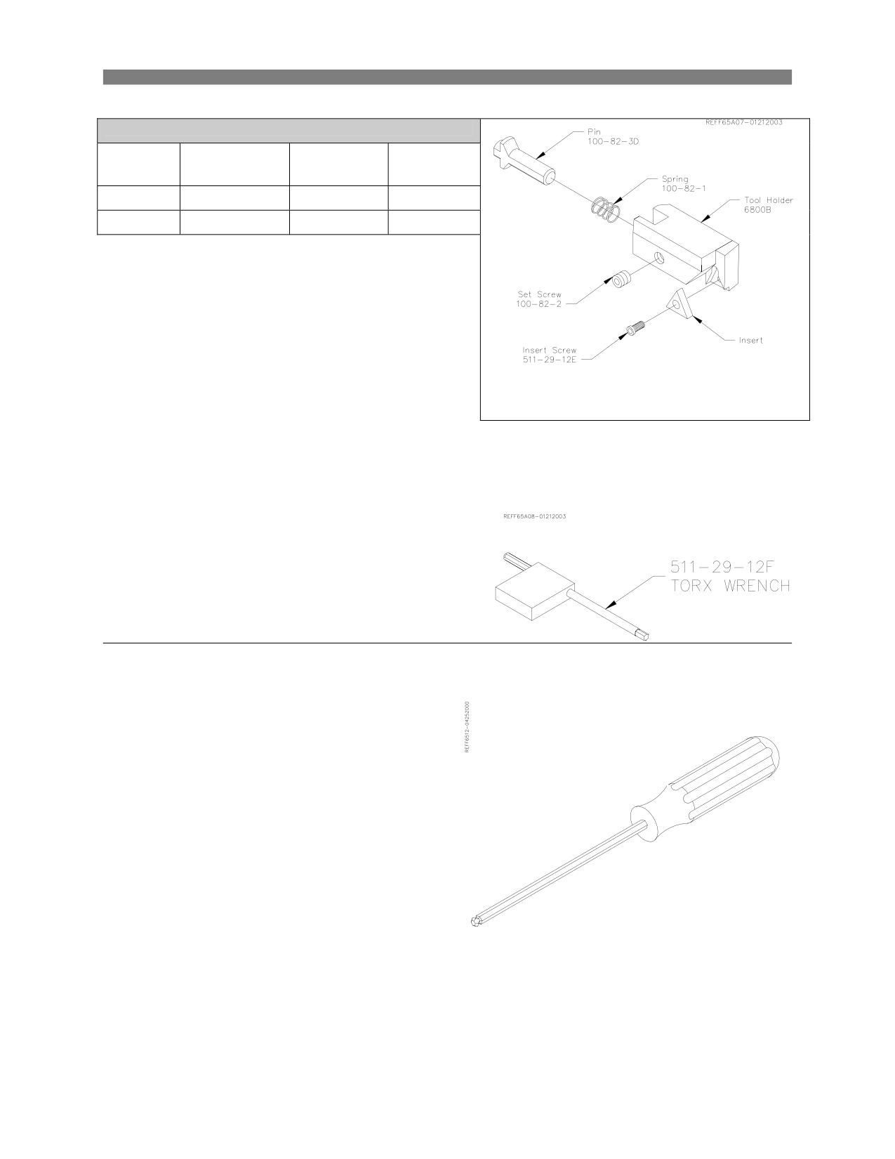
Options
6-75
F65 Manual
1.9” Cutterhead Standard Tooling:
6802B Tool Holder
Assembly
Tool Holder
Length
Part #
Part #
6802B
6800B
2.082”
6802C
6800C
2.3” - 2.7”
optional
Triangle insert positive
rake. 6802C requires a
3/8” IC insert.
511-29-12F Torx Wrench:
501-72A Hex Driver:
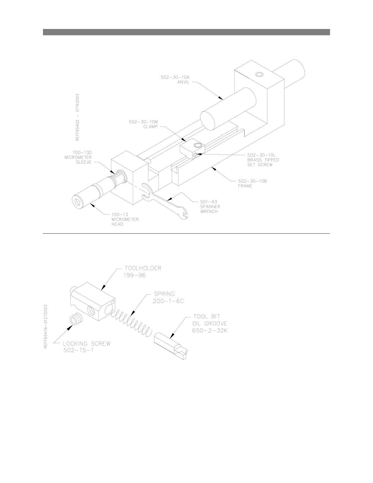
Options
6-76
F65 Manual
900-2-11 Micrometer Assembly:
1.5” - 4.1”
Oil Groove Tooling:
Options
6-77
F65 Manual
Boring Inserts:
Speeds and Feed Rates will vary from Cutter Head to Cutter Head when using the same insert due to the
different properties of each Cutter Head.
Boring Speeds and Feeds:
The Following insert feeds and speeds are designed to be used with the 650-2-3F Cutter Head Assembly.
Below is a description of the cutting inserts available from Rottler. The inserts have gone through
extensive performance testing. To take full advantage of the capabilities of your Rottler Machine, we
highly recommend Rottler tooling be used. This chart uses SFM or Surface Feet Per Minute as a speed
reference. To calculate SFM to RPM use the following formula.
RPM = SFM X 3.83
DIAMETER
Example:
SFM = 800
4.00” Bore
800 X 3.83 = 3064 Divide by the diameter 4.00 = 766 RPM
Insert
Part #
Description
Application
RT211
A 3/8” IC triangular insert
The ceramic coating gives excellent results for
with a dark purple ceramic
both heavy sleeve cutting and finishing of cast
coating and 1/64” cutting
iron and nodular cast iron. The 1/64” will
radius.
minimize the possibility of chatter on a line
bore. A feed rate of .002 - .003 should be
used to obtain a typical surface finish. A
speed of 200 to 400 SFM should be used for
best results.
RT221
This is the same insert as
This larger radius insert will give a smoother
RT321, except it has a 1/32”
finish but increase the possibility of chatter. A
radius.
feed rate of .002 - .003 should be used to
obtain a typical surface finish. A speed of 200
to 400 SFM should be used for best results.
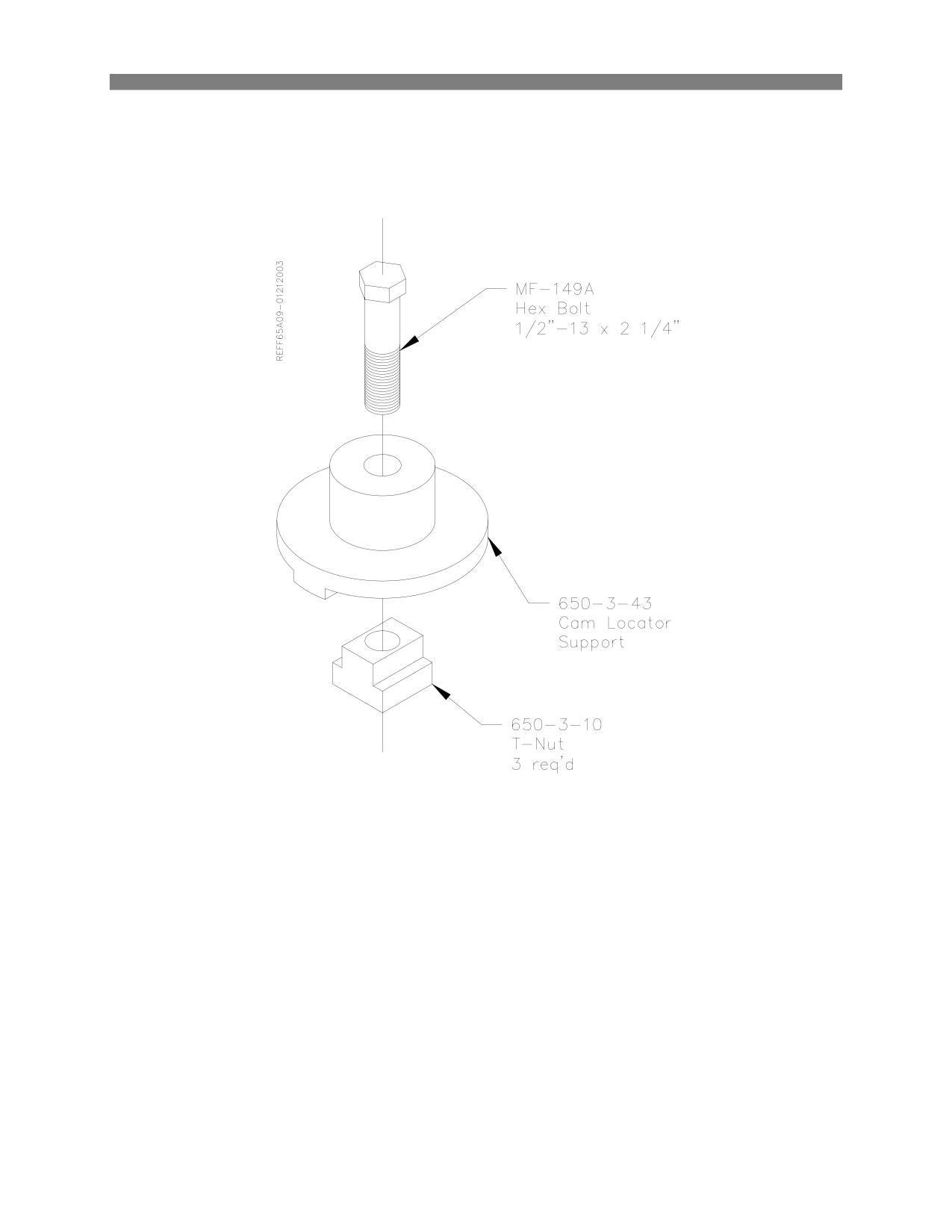
Options
6-78
F65 Manual
Cam Locator Support:
650-3-43
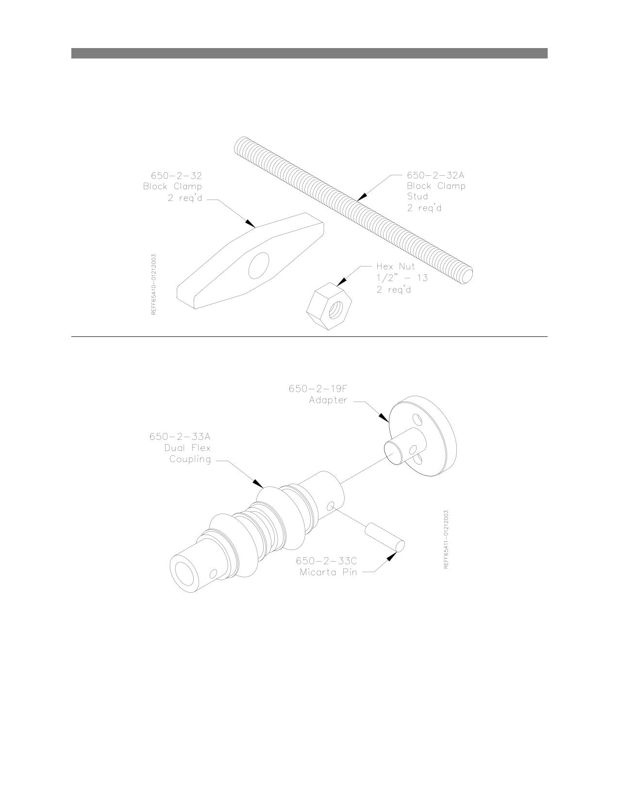
Options
6-79
F65 Manual
Block Clamp:
650-2-32
Block Clamp Stud:
650-2-32A
Adapter and Dual Flex Coupling Assembly:
650-2-19G
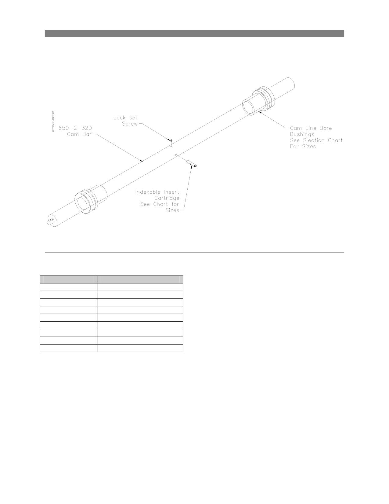
Options
6-80
F65 Manual
Cam Line Boring Bar:
650-2-32D
Cam Line Bore Bushings:
Part Number
Bushing Sizes
650-3-43B
63mm (2.480” +/- .0007”)
650-3-43C
58mm (2.282” +/- .0007”)
650-3-43D
(2.250” +/- .0007”)
650-3-43E
(2.790” +/- .0007”)
650-3-43F
(2.309” +/- .0007”)
650-3-43G
(2.500” +/- .0007”)
650-3-43H
(2.120” +/- .0007”)
650-3-43J
(2.030” +/- .0007”)
650-3-43K
(2.040” +/- .0015”)
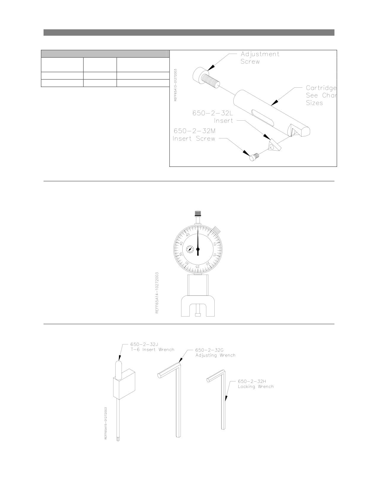
Options
6-81
F65 Manual
Cam Line Boring Cartridges:
Cam Line Bore Cartridges:
Part
Length
Range
Number
650-2-32E
1.530”
1.985” - 2.650”
650-2-32F
1.650”
2.250” - 2.850”
Tool Setting Indicator:
650-2-33
Wrenches: