BB4500-BB5000 BORING MACHINE. OPERATING MANUAL
BB4500-
BB5000
BORING MACHINE
OPERATING MANUAL
ORIGINAL INSTRUCTIONS
BB4500
BB5000
P/N 92974
February 2021
• Your name
• Shipping address
• Telephone number
• Machine model
• Serial number (if applicable)
• Date of purchase
CLIMAX World Headquarters
H&S Tool World Headquarters
2712 East 2nd Street
715 Weber Dr.
Newberg, Oregon 97132 USA
Wadsworth, OH 44281 USA
Telephone (worldwide): +1-503-538-2815
Telephone: +1-330-336-4550
Toll-free (North America): 1-800-333-8311
Fax: 1-330-336-9159
Fax: 503-538-7600
hstool.com
CLIMAX | H&S Tool (UK Headquarters)
CLIMAX | H&S Tool (European Headquarters)
Unit 7 Castlehill Industrial Estate
Am Langen Graben 8
Bredbury Industrial Park
52353 Düren, Germany
Horsfield Way
Telephone: +49 24-219-1770
Stockport SK6 2SU, UK
E-mail: ClimaxEurope@cpmt.com
Telephone: +44 (0) 161-406-1720
CLIMAX | H&S Tool (Asia Pacific Head-
CLIMAX | H&S Tool (Middle East Headquarters)
quarters)
Warehouse #5, Plot: 369 272
316 Tanglin Road #02-01
Um Sequim Road
Singapore 247978
Al Quoz 4
PO Box 414 084
Telephone: +65 9647-2289
Dubai, UAE
Fax: +65 6801-0699
Telephone: +971 04-321-0328
P/N 92974, Rev. 3
Page A
CLIMAX GLOBAL LOCATIONS
Page B
BB4500-BB5000 Operating Manual
CE DOCUMENTATION
P/N 92974, Rev. 3
Page C
LIMITED WARRANTY
CLIMAX Portable Machine Tools, Inc. (hereafter referred to as “CLIMAX”) warrants that all new machines
are free from defects in materials and workmanship. This warranty is available to the original purchaser for a
period of one year after delivery. If the original purchaser finds any defect in materials or workmanship
within the warranty period, the original purchaser should contact its factory representative and return the
entire machine, shipping prepaid, to the factory. CLIMAX will, at its option, either repair or replace the
defective machine at no charge and will return the machine with shipping prepaid.
CLIMAX warrants that all parts are free from defects in materials and workmanship, and that all labor has
been performed properly. This warranty is available to the customer purchasing parts or labor for a period of
90 days after delivery of the part or repaired machine or 180 days on used machines and components. If the
customer purchasing parts or labor finds any defect in materials or workmanship within the warranty period,
the purchaser should contact its factory representative and return the part or repaired machine, shipping pre-
paid, to the factory. CLIMAX will, at its option, either repair or replace the defective part and/ or correct any
defect in the labor performed, both at no charge, and return the part or repaired machine shipping prepaid.
These warranties do not apply to the following:
• Damage after the date of shipment not caused by defects in materials or workmanship
• Damage caused by improper or inadequate machine maintenance
• Damage caused by unauthorized machine modification or repair
• Damage caused by machine abuse
• Damage caused by using the machine beyond its rated capacity
All other warranties, express or implied, including without limitation the warranties of merchantability and
fitness for a particular purpose are disclaimed and excluded.
Terms of sale
Be sure to review the terms of sale which appear on the reverse side of your invoice. These terms control and
limit your rights with respect to the goods purchased from CLIMAX.
About this manual
CLIMAX provides the contents of this manual in good faith as a guideline to the operator. CLIMAX cannot
guarantee that the information contained in this manual is correct for applications other than the application
described in this manual. Product specifications are subject to change without notice.
Page D
BB4500-BB5000 Operating Manual
TABLE OF CONTENTS
CHAPTER/SECTION
PAGE
1
INTRODUCTION
1
1.1
HOW TO USE THIS MANUAL
1
1.2
SAFETY ALERTS
1
1.3
GENERAL SAFETY PRECAUTIONS
2
1.4
MACHINE-SPECIFIC SAFETY PRECAUTIONS
3
1.5
RISK ASSESSMENT AND HAZARD MITIGATION
4
1.6
RISK ASSESSMENT CHECKLIST
5
1.7
LABELS
6
1.7.1
Label identification
6
1.7.2
BB4500-BB5000 label locations
7
2
OVERVIEW
11
2.1
BB4500 FEATURES
12
2.2
BB5000 FEATURES
13
2.3
COMPONENTS
13
2.3.1
Rotational drive unit
13
2.3.2
Axial feed unit
14
2.3.3
Leadscrew
14
2.3.4
BB4500 tool heads
14
2.3.5
BB5000 tool heads
14
2.3.6
BB4500 boring bar
15
2.3.7
BB5000 boring bar
15
2.3.8
Spherical bearing mounts
16
2.4
CONTROLS
17
2.4.1
Hydraulic power unit and hydraulic motors
18
2.4.2
BB5000 servo motors
19
2.4.3
Electric motor
21
2.4.4
Air motor
24
2.4.5
Pneumatic conditioning unit
24
2.5
DIMENSIONS
25
2.6
SPECIFICATIONS
27
2.6.1
Electrical specifications
28
2.7
ITEMS REQUIRED BUT NOT SUPPLIED
29
3
SETUP
31
3.1
RECEIPT AND INSPECTION
31
3.2
LIFTING AND RIGGING
32
3.3
MACHINE ASSEMBLY
32
P/N 92974, Rev. 3
Page i
TABLE OF CONTENTS (CONTINUED)
CHAPTER/SECTION
PAGE
3.3.1
Bar and mounting bracket assembly
33
3.3.2
Tooling and tool head assembly
35
3.3.3
RDU and AFU assembly
37
3.4
AXIAL FEED
40
3.4.1
Selecting the feed direction
40
3.4.2
Setting the feed rate
41
3.4.3
Automatic feed stop
42
3.5
POWER CONNECTION
43
3.5.1
Hydraulic machines
43
3.5.2
BB5000 servo drive machine
44
3.5.3
Electrical machines
46
3.5.4
Pneumatic machines
46
3.6
BB4500-BB5000 WITH SMALL DIAMETER BARS
47
4
OPERATION
51
4.1
PRE-OPERATION CHECKS
51
4.2
TOOL BIT SELECTION
52
4.3
OPERATION
52
4.3.1
Starting the machine
52
4.4
SHUTDOWN
54
4.5
DISASSEMBLY
55
5
MAINTENANCE
57
5.1
MAINTENANCE CHECKLIST
57
5.2
APPROVED LUBRICANTS
58
5.3
MAINTENANCE TASKS
59
5.3.1
AFU
59
5.3.2
Boring bar
59
5.3.3
Hydraulic power system
59
5.3.4
Electric motor assembly
60
5.3.5
Air motor assembly
60
5.3.6
BB5000 servo motor
61
5.3.7
4:1 RDU gearbox
61
5.3.8
Cutting fluid
61
5.4
QUALITY CHECKS
61
5.5
TROUBLESHOOTING
62
6
STORAGE AND SHIPPING
63
6.1
STORAGE
63
Page ii
BB4500-BB5000 Operating Manual
TABLE OF CONTENTS (CONTINUED)
CHAPTER/SECTION
PAGE
6.1.1
Short-term storage
63
6.1.2
Long-term storage
63
6.2
SHIPPING
63
6.3
DECOMMISSIONING
64
APPENDIX A BB4500 ASSEMBLY DRAWINGS
65
APPENDIX B BB5000 ASSEMBLY DRAWINGS
85
APPENDIX C SCHEMATICS
121
APPENDIX D SERVO CONTROLS ADJUSTMENT
143
APPENDIX E SDS
145
P/N 92974, Rev. 3
Page iii
This page intentionally left blank
Page iv
BB4500-BB5000 Operating Manual
LIST OF FIGURES
FIGURE
PAGE
1-1 AFU label locations
8
1-2 RDU label locations
9
2-1 BB4500-BB5000 components with Eibenstock motor (BB5000 shown)
12
2-2 RDU
13
2-3 AFU
14
2-4 BB4500 tool heads
14
2-5 BB5000 tool heads
15
2-6 Single-arm spherical bearing mount
16
2-7 Double-arm spherical bearing mount
16
2-8 Universal spherical bearing mount
16
2-9 BB5000 servo drive dimensions
20
2-10 RDU and Eibenstock motor dimensions
21
2-11 Air motor
24
2-12 Pneumatic conditioning unit
25
2-13 BB4500 dimensions
26
2-14 BB5000 dimensions
26
3-1 Setup cones
33
3-2 Boring bar insertion
33
3-3 Setup cone installation
34
3-4 Centering the spherical bearings
34
3-5 Positioning the spherical bearings
35
3-6 Aligning the bar
35
3-7 Inserting the tool bit
36
3-8 Tool head setup
36
3-9 Positioning the RDU
37
3-10 Positioning the AFU
38
3-11 Clamp collars on the AFU
39
3-12 AFU components
40
3-13 Feed box arrows
41
3-14 Automatic feed stop
42
3-15 Servo motor main control panel
44
3-16 Servo motor pendant controls
45
3-17 Air control valve handle
46
3-18 Collets (BB5000 version shown)
47
3-19 BB5000 RDU collet keyway
48
3-20 Snap ring removal
48
3-21 Small bore kit adapter insertion
49
3-22 Snap ring replacement
50
4-1 Disengaging the axial feed
54
4-2 AFU disassembly components
56
5-1 Electric motor with handle
60
A-1 Axial feed unit assembly (P/N 43378)
66
A-2 Axial feed unit assembly parts list (P/N 43378)
67
A-3 Boring heads set assembly (P/N 43576)
68
P/N 92974, Rev. 3
Page v
LIST OF FIGURES (CONTINUED)
FIGURE
PAGE
A-4 Boring heads set 4-10 metric diameter assembly (P/N 43576)
69
A-5 Boring heads set 4-10" diameter assembly (P/N 43575)
70
A-6 RDU 2nd gen assembly (P/N 53912)
71
A-7 RDU 2nd gen assembly (P/N 53912)
72
A-8 Hydraulic motor assembly (P/N 39848)
73
A-9 Single-arm mount assembly (P/N 43262)
74
A-10 Universal mount assembly (P/N 43267)
75
A-11 Double-arm bearing mount assembly (P/N 43279)
76
A-12 Large and small set cones assembly (P/N 49060)
77
A-13 Eibenstock motor assembly (P/N 88012)
78
A-14 Eibenstock motor assembly -- gen. 2 only
79
A-15 Eibenstock motor assembly parts list -- gen. 2 only
80
B-1 Axial feed unit assembly (P/N 28636)
86
B-2 Axial feed unit assembly parts list (P/N 28636)
87
B-3 HD axial feed unit assembly (P/N 91518)
88
B-4 HD axial feed unit assembly parts list (P/N 91518)
89
B-5 Air motor CE assembly (P/N 28697)
90
B-6 Air motor CE assembly (P/N 28614)
91
B-7 Pneumatic connection assembly (P/N 15088)
92
B-8 Hydraulic motor assembly (P/N 39848)
93
B-9 Single-arm mount assembly (P/N 37472)
94
B-10 Double-arm mount assembly (P/N 37473)
95
B-11 Universal bearing mount assembly (P/N 36959)
96
B-12 ID bearing mount assembly (P/N 46293)
97
B-13 Setup cones 2.75-8.37" (70-213 mm) diameter assembly (P/N 26507)
98
B-14 Setup cones 8.37-12" (213-305 mm) diameter assembly (P/N 26508)
99
B-15 Servo drive 460 CE assembly (P/N 52876)
100
B-16 Servo drive 460 CE assembly parts list (P/N 52876)
101
B-17 RDU 12:1 assembly (P/N 53165)
102
B-18 RDU 12:1 assembly parts list (P/N 53165)
103
B-19 RDU 4th generation assembly (P/N 49684)
104
B-20 RDU 4th generation assembly parts list (P/N 49684)
105
B-21 Servo drive 230V CE assembly (P/N 54321)
106
B-22 Servo drive 230V CE assembly (P/N 54321)
107
B-23 Servo motor RDU adapter assembly (P/N 51536)
108
B-24 Servo motor guard assembly (P/N 52937)
109
B-25 Servo shroud fan assembly (P/N 56773)
110
B-26 Servo drive motor 230V non-CE assembly (P/N 71071)
111
B-27 Servo drive motor 460V non-CE assembly (P/N 71072)
112
B-28 Eibenstock motor assembly -- gen. 2 only
113
B-29 Eibenstock motor assembly parts list -- gen. 2 only
114
B-30 Leadscrew assembly (P/N 28654)
115
C-1 BB4500-BB5000 Eibenstock controller 2nd gen 230V 50-60 hz CE schematic (P/N 88035 C00467) 122
C-2 BB4500-BB5000 Eibenstock controller 2nd gen 230V 50-60 hz domestic assembly (P/N 88036 C00468)
123
Page vi
BB4500-BB5000 Operating Manual
LIST OF FIGURES (CONTINUED)
FIGURE
PAGE
C-3 BB4500-BB5000 Eibenstock controller 2nd gen 120V domestic assembly (P/N 88037 C00465) . . . 124
C-4 BB4500-BB5000 Eibenstock controller 2nd gen 120V CE assembly (P/N 88038 C00466)
125
C-5 BB5000 motor 230V and 460V fan assembly (P/N 91811 E00034)
126
C-6 BB5000 servo motor 230VAC and 460VAC power cable assembly (P/N 91811 E00048)
127
C-7 BB5000 Eibenstock motor cable assembly 2nd gen 120V 12AWG schematic (P/N 88649 E00170). 128
C-8 BB5000 Eibenstock motor cable assembly 2nd gen 230V 14AWG schematic (P/N 88650 E00171). 129
C-9 BB5000 Eibenstock power cable assembly 2nd gen 120V domestic L5-30P plug (P/N 88652 E00172).
130
C-10 BB5000 Eibenstock power cable assembly 2nd gen 120V CE 332P4W pin/sleeve plug (P/N 88653
E00173)
131
C-11 BB5000 Eibenstock power cable assembly 2nd gen 230V CE CEE7/7 Schuko plug (P/N 88654 E00174)
132
C-12 BB5000 Eibenstock power cable assembly 2nd gen 230V domestic L6-15P plug (P/N 88655 E00175)
133
C-13 Pneumatic conditioning unit schematic (P/N 59248)
134
C-14 BB4500-BB5000 Eibenstock controller 2nd gen 230V 50-60 hz CE assembly (P/N 88035 B00367) 135
C-15 BB4500-BB5000 Eibenstock controller 2nd gen 230V 50-60 hz domestic assembly (P/N 88036 B00368)
136
C-16 BB4500-BB5000 Eibenstock controller 2nd gen 120V domestic assembly (P/N 88037 B00365) . . 137
C-17 BB4500-BB5000 Eibenstock controller 2nd gen 120V CE assembly (P/N 88038 B00366)
138
C-18 BB5000 servo controller 3rd gen 460VAC CE assembly (P/N A00099)
139
C-19 BB5000 Eibenstock controller 2nd gen 120V domestic assembly (P/N A00100)
140
C-20 BB5000 servo pendant assembly (P/N B00024)
141
D-1 Servo amp function keys
143
P/N 92974, Rev. 3
Page vii
This page intentionally left blank
Page viii
BB4500-BB5000 Operating Manual
LIST OF TABLES
TABLE
PAGE
1-1 Sound levels
3
1-2 Risk assessment checklist before set-up
5
1-3 Risk assessment checklist after set-up
5
1-4 BB4500-BB5000 labels
6
2-1 BB5000 component identification
12
2-2 Power options
17
2-3 Test data
17
2-4 Setup cones
17
2-5 Available HPU specifications
18
2-6 Hydraulic motor specifications
19
2-7 BB5000 servo motor specification
20
2-8 Control box
21
2-10 Speed range and torque per gear
22
2-11 Recommended wire gauge for extension cords
22
2-9 Power rating
22
2-12 120V service parts
23
2-13 230V service parts
23
2-14 Control box
24
2-15 Bar RPM and torque at maximum hp
24
2-16 Dimensions
25
2-17 BB4500-BB5000 boring bar dimension identification
27
2-18 Sub-component mass
27
2-19 Boring specifications
27
2-20 Electrical specifications
28
3-1 Setup cone identification
33
3-2 Setup cone installation identification
34
3-3 Spherical bearing identification
35
3-4 Tool head setup identification
36
3-5 Clamp collars installation identification
39
3-6 AFU component identification
41
3-7 Feed box arrow identification
41
3-8 Automatic feed stop identification
42
3-9 Servo motor control functions
45
3-10 Collet identification
47
3-11 RDU collet keyway identification
48
3-12 Snap ring removal identification
49
3-13 Small bore kit adapter identification
49
3-14 Snap ring replacement identification
50
4-1 Axial feed disengagement identification
54
4-2 AFU disassembly identification
56
5-1 Maintenance intervals and tasks
57
5-2 Approved lubricants
58
5-3 Quality checks
61
5-4 Troubleshooting
62
P/N 92974, Rev. 3
Page ix
LIST OF TABLES (CONTINUED)
TABLE
PAGE
A-1 BB4500 recommended spare parts
81
A-2 BB4500-BB5000 spare parts kit (P/N 97276)
81
A-3 BB4500 tool kit in inches (P/N 43580)
82
A-4 BB4500 tool kit in metric (P/N 43582)
83
B-1 BB5000 recommended spare parts
116
B-2 BB4500-BB5000 spare parts kit (P/N 97276)
117
B-3 Leadscrew spare parts
117
B-4 Hydraulic metric spare parts
118
B-5 BB5000 tool kit in inches (P/N 28784)
119
B-6 BB5000 tool kit in metric (P/N 34580)
119
Page x
BB4500-BB5000 Operating Manual
1
INTRODUCTION
IN THIS CHAPTER:
1.1 HOW TO USE THIS MANUAL - - - - - - - - - - - - - - - - - - - - - - - - - - - - - - - - - - - - - -
1
1.2 SAFETY ALERTS - - - - - - - - - - - - - - - - - - - - - - - - - - - - - - - - - - - - - - - - - - -
1
1.3 GENERAL SAFETY PRECAUTIONS
- - - - - - - - - - - - - - - - - - - - - - - - - - - - - - - - - - -
2
1.4 MACHINE-SPECIFIC SAFETY PRECAUTIONS - - - - - - - - - - - - - - - - - - - - - - - - - - - - - - -
3
1.5 RISK ASSESSMENT AND HAZARD MITIGATION - - - - - - - - - - - - - - - - - - - - - - - - - - - - - -
4
1.6 RISK ASSESSMENT CHECKLIST
- - - - - - - - - - - - - - - - - - - - - - - - - - - - - - - - - - - -
5
1.7 LABELS - - - - - - - - - - - - - - - - - - - - - - - - - - - - - - - - - - - - - - - - - - - - - - -
6
1.7.1 LABEL IDENTIFICATION - - - - - - - - - - - - - - - - - - - - - - - - - - - - - - - - - - - - -
6
1.7.2 BB4500-BB5000 LABEL LOCATIONS
- - - - - - - - - - - - - - - - - - - - - - - - - - - - - -
7
1.1
HOW TO USE THIS MANUAL
This manual describes information necessary for the setup, operation, mainte-
nance, storage, shipping, and decommissioning of the BB4500-BB5000.
The first page of each chapter includes a summary of the chapter contents to help
you locate specific information. The appendices contain supplemental product
information to aid in setup, operation, and maintenance tasks.
Read this entire manual to familiarize yourself with the BB4500-BB5000 before
attempting to set it up or operate it.
1.2
SAFETY ALERTS
Pay careful attention to the safety alerts printed throughout this manual. Safety
alerts will call your attention to specific hazardous situations that may be encoun-
tered when operating this machine.
Examples of safety alerts used in this manual are defined here1:
DANGER
indicates a hazardous situation which, if not avoided, WILL result in
death or severe injury.
WARNING
indicates a hazardous situation which, if not avoided, COULD result in
death or severe injury.
1. For more information on safety alerts, refer to ANSI/NEMA Z535.6-2011, Product
safety Information in Product Manuals, Instructions, and Other Collateral Materials.
P/N 92974, Rev. 3
Page 1
CAUTION
indicates a hazardous situation which, if not avoided, could result in
minor or moderate injury.
NOTICE
indicates a hazardous situation which, if not avoided, could result in
property damage, equipment failure, or undesired work results.
1.3
GENERAL SAFETY PRECAUTIONS
CLIMAX leads the way in promoting the safe use of portable machine tools and
valve testers. Safety is a joint effort. You, the end user, must do your part by being
aware of your work environment and closely following the operating procedures
and safety precautions contained in this manual, as well as your employer’s safety
guidelines.
Observe the following safety precautions when operating or working around the
machine.
Training - Before operating this or any machine tool, you should receive
instruction from a qualified trainer. Contact CLIMAX for machine-specific
training information.
Risk assessment - Working with and around this machine poses risks to
your safety. You, the end user, are responsible for conducting a risk assess-
ment of each job site before setting up and operating this machine.
Intended use - Use this machine in accordance with the instructions and
precautions in this manual. Do not use this machine for any purpose other
than its intended use as described in this manual.
Personal protective equipment - Always wear appropriate personal pro-
tective gear when operating this or any other machine tool. Flame-resistant
clothing with long sleeves and legs is recommended when operating the
machine. Hot chips from the workpiece may burn or cut bare skin.
Work area - Keep the work area around the machine clear of clutter. Restrain
cords and hoses connected to the machine. Keep other cords and hoses
away from the work area.
Lifting - Many CLIMAX machine components are very heavy. Whenever
possible, lift the machine or its components using proper hoisting equip-
ment and rigging. Always use designated lifting points on the machine.
Follow lifting instructions in the setup procedures of this manual.
Lock-out/tag-out - Lock-out and tag-out the machine before performing
maintenance.
Moving parts - CLIMAX machines have numerous exposed moving parts
Page 2
BB4500-BB5000 Operating Manual
and interfaces that can cause severe impact, pinching, cutting, and other
injuries. Except for stationary operating controls, avoid contact with mov-
ing parts by hands or tools during machine operation. Remove gloves and
secure hair, clothing, jewelry, and pocket items to prevent them from
becoming entangled in moving parts.
Sharp edges - Cutting tools and workpieces have sharp edges that can eas-
ily cut skin. Wear protective gloves and exercise caution when handling a
cutting tool or workpiece.
Hot surfaces - During operation, motors, pumps, HPUs, and cutting tools
can generate enough heat to cause severe burns. Pay attention to hot sur-
face labels, and avoid contact with bare skin until the machine has cooled.
1.4
MACHINE-SPECIFIC SAFETY PRECAUTIONS
Eye hazard - This machine produces metal chips during operation. Always
wear eye protection when operating the machine.
Sound level - This machine produces potentially harmful sound levels.
Hearing protection is required when operating this machine or working
around it. During testing, the machine produced the sound levels1 listed in
Table 1-1.
TABLE 1-1. SOUND LEVELS
BB4500 motor
BB5000 motor
Sound power
90.0 dBA
94.0 dBA
Operator sound pressure
91.4 dBA
91.4 dBA
Bystander sound pressure
89.6 dBA
89.6 dBA
Hazardous environments - Do not operate the machine in environments
where potentially explosive materials, toxic chemicals, or radiation may be
present.
Machine mounting - Do not operate the machine unless mounted to a
workpiece in accordance with this manual. If mounting the machine in an
overhead or vertical position, do not remove hoist rigging until the machine
is mounted to the workpiece in accordance with this manual.
1. Machine sound testing was conducted in accordance with European Harmonized
Standards EN ISO 3744:2010 and EN 11201:2010.
P/N 92974, Rev. 3
Page 3
1.5
RISK ASSESSMENT AND HAZARD MITIGATION
Machine Tools are specifically designed to perform precise material-removal oper-
ations.
Stationary Machine Tools include lathes and milling machines and are typically
found in a machine shop. They are mounted in a fixed location during operation
and are considered to be a complete, self-contained machine. Stationary Machine
Tools achieve the rigidity needed to accomplish material-removal operations from
the structure that is an integral part of the machine tool.
In contrast, Portable Machine Tools are designed for on-site machining applica-
tions. They typically attach directly to the workpiece itself, or to an adjacent struc-
ture, and achieve their rigidity from the structure to which it is attached. The
design intent is that the Portable Machine Tool and the structure to which it is
attached become one complete machine during the material-removal process.
To achieve the intended results and to promote safety, the operator must under-
stand and follow the design intent, set-up, and operation practices that are unique
to Portable Machine Tools.
The operator must perform an overall review and on-site risk assessment of the
intended application. Due to the unique nature of portable machining applications,
identifying one or more hazards that must be addressed is typical.
When performing the on-site risk assessment, it is important to consider the Porta-
ble Machine Tool and the workpiece as a whole.
Page 4
BB4500-BB5000 Operating Manual
1.6
RISK ASSESSMENT CHECKLIST
The following checklist is not intended to be an all inclusive list of things to watch
out for when setting up and operating this Portable Machine Tool. However, these
checklists are typical of the types of risks the assembler and operator should con-
sider. Use these checklists as part of your risk assessment:
TABLE 1-2. RISK ASSESSMENT CHECKLIST BEFORE SET-UP
Before set-up
I took note of all the warning labels on the machine.
I removed or mitigated all identified risks (such as tripping, cutting, crushing, entan-
glement, shearing, or falling objects).
I considered the need for personnel safety guarding and installed any necessary
guards.
I read the machine assembly instructions (Section 3.3) and took inventory of all the
items required but not supplied (Section 2.7).
I created a lift plan, including identifying the proper rigging, for each of the setup
lifts required during the setup of the support structure and machine.
I located the fall paths involved in lifting and rigging operations. I have taken pre-
cautions to keep workers away from the identified fall path.
I considered how this machine operates and identified the best placement for the
controls, cabling, and the operator.
I evaluated and mitigated any other potential risks specific to my work area.
TABLE 1-3. RISK ASSESSMENT CHECKLIST AFTER SET-UP
After set-up
I checked that the machine is safely installed (according to Section 3) and the
potential fall path is clear. If the machine is installed at an elevated position, I
checked that the machine is safeguarded against falling.
I identified all possible pinch points, such as those caused by rotating parts, and
informed the affected personnel.
I planned for containment of any chips or swarf produced by the machine.
I followed the required maintenance checklist (Section 5.1) with the recommended
lubricants (Section 5.2).
I checked that all affected personnel have the recommended personal protective
equipment, as well as any site-required or regulatory equipment.
I checked that all affected personnel understand and are clear of the danger zone.
I evaluated and mitigated any other potential risks specific to my work area.
P/N 92974, Rev. 3
Page 5
1.7
LABELS
1.7.1
Label identification
The following warning and identification labels should be on your machine. If any
are defaced or missing, contact CLIMAX immediately for replacements.
TABLE 1-4. BB4500-BB5000 LABELS
P/N 59037
P/N 29154
Warning label:
Serial number
read the operating
plate
manual
P/N 59044
P/N 77568
Warning label:
ICE electrical
read the operat-
symbol
ing manual
P/N 78735
P/N 78619
Warning label:
Warning label:
hand crush haz-
hot surface
ard
P/N 78742
P/N 78741
Warning label:
Warning label:
entanglement
foot crush haz-
hazard with rotat-
ard
ing shaft
Page 6
BB4500-BB5000 Operating Manual
TABLE 1-4. BB4500-BB5000 LABELS (CONTINUED)
P/N 78824
P/N 78748
Warning label: do
Warning label:
not expose the
eye protection
plug to water;
electrical hazard
P/N 80207
P/N 80510
Warning label:
entanglement
Warning label:
danger with
cutting hazard
rotating shaft
1.7.2
BB4500-BB5000 label locations
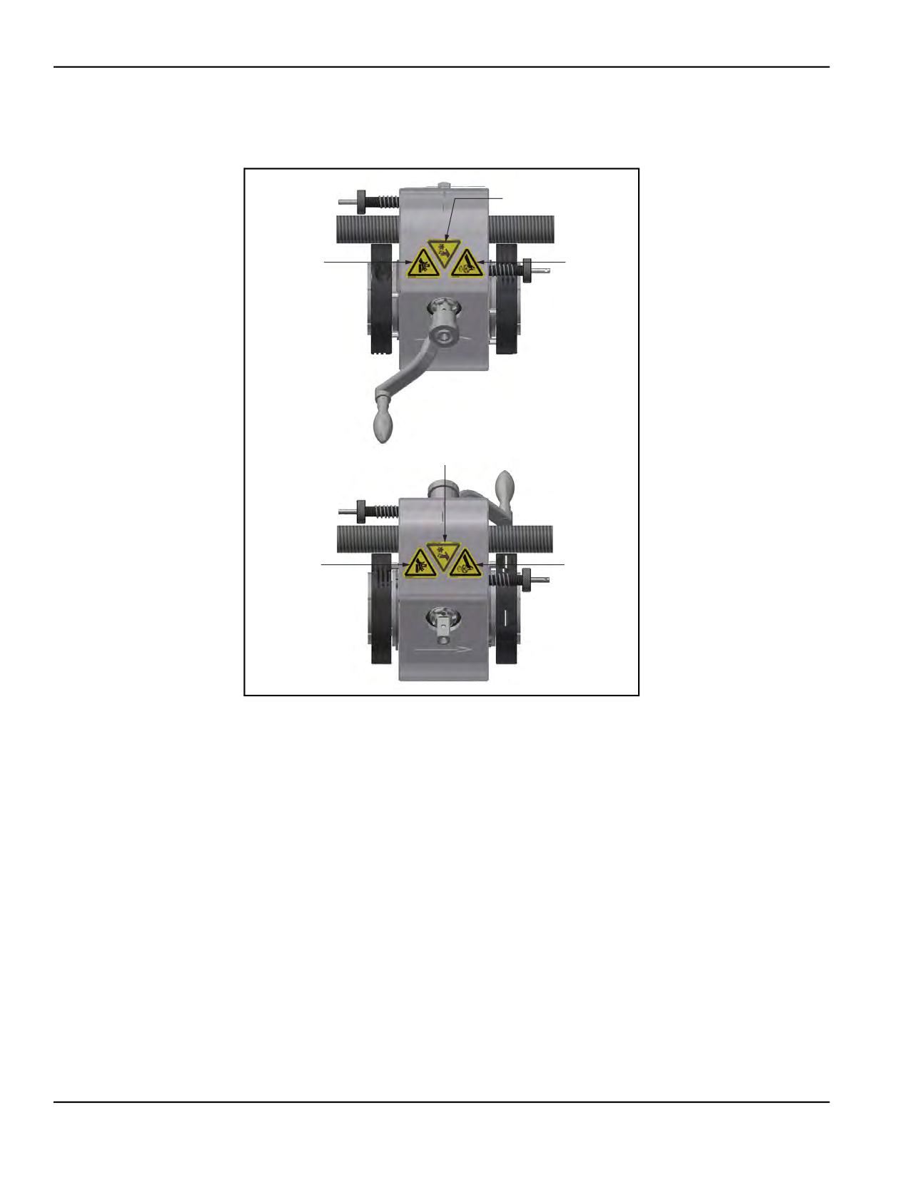
The following figures display the location of the labels on the RDU and AFU. For
further identification of location placement, refer to the BB4500 exploded views in
Appendix A on page 65 and the BB5000 exploded views in Appendix B on page
85.
P/N 92974, Rev. 3
Page 7
80510
78735
78742
80510
78735
78742
FIGURE 1-1. AFU LABEL LOCATIONS
Page 8
BB4500-BB5000 Operating Manual
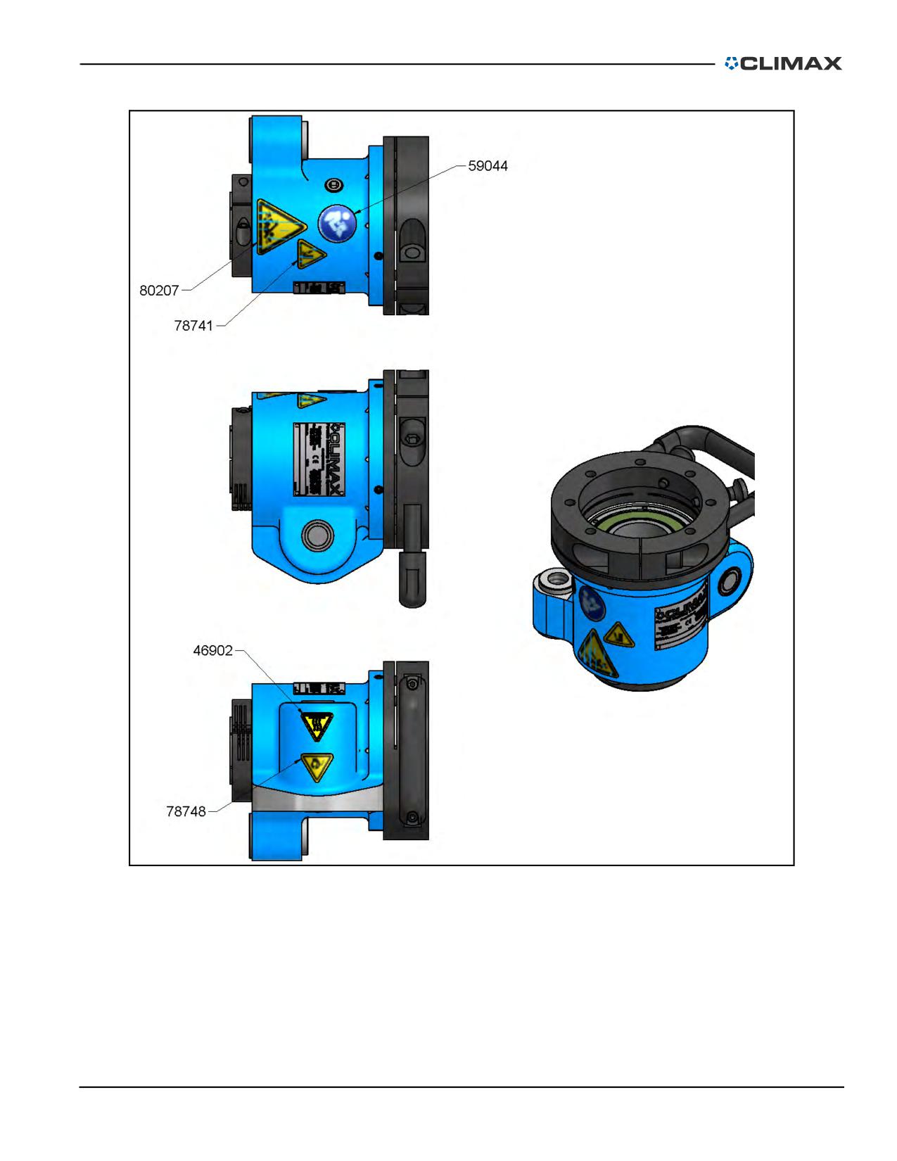
FIGURE 1-2. RDU LABEL LOCATIONS
P/N 92974, Rev. 3
Page 9
This page intentionally left blank
Page 10
BB4500-BB5000 Operating Manual
2
OVERVIEW
IN THIS CHAPTER:
2.1 BB4500 FEATURES
- - - - - - - - - - - - - - - - - - - - - - - - - - - - - - - - - - - - - - - -
-12
2.2 BB5000 FEATURES
- - - - - - - - - - - - - - - - - - - - - - - - - - - - - - - - - - - - - - - -
-13
2.3 COMPONENTS - - - - - - - - - - - - - - - - - - - - - - - - - - - - - - - - - - - - - - - - - - -
-13
2.3.1 ROTATIONAL DRIVE UNIT - - - - - - - - - - - - - - - - - - - - - - - - - - - - - - - - - - -
-13
2.3.2 AXIAL FEED UNIT - - - - - - - - - - - - - - - - - - - - - - - - - - - - - - - - - - - - - - -
-14
2.3.3 LEADSCREW - - - - - - - - - - - - - - - - - - - - - - - - - - - - - - - - - - - - - - - - -
-14
2.3.4 BB4500 TOOL HEADS
- - - - - - - - - - - - - - - - - - - - - - - - - - - - - - - - - - - -
-14
2.3.5 BB5000 TOOL HEADS
- - - - - - - - - - - - - - - - - - - - - - - - - - - - - - - - - - - -
-14
2.3.6 BB4500 BORING BAR
- - - - - - - - - - - - - - - - - - - - - - - - - - - - - - - - - - - -
-15
2.3.7 BB5000 BORING BAR
- - - - - - - - - - - - - - - - - - - - - - - - - - - - - - - - - - - -
-15
2.3.8 SPHERICAL BEARING MOUNTS - - - - - - - - - - - - - - - - - - - - - - - - - - - - - - - - -
-16
2.4 CONTROLS
- - - - - - - - - - - - - - - - - - - - - - - - - - - - - - - - - - - - - - - - - - - -
-17
2.4.1 HYDRAULIC POWER UNIT AND HYDRAULIC MOTORS - - - - - - - - - - - - - - - - - - - - - - - -18
2.4.2 BB5000 SERVO MOTORS - - - - - - - - - - - - - - - - - - - - - - - - - - - - - - - - - - - -19
2.4.3 ELECTRIC MOTOR - - - - - - - - - - - - - - - - - - - - - - - - - - - - - - - - - - - - - -
-21
2.4.4 AIR MOTOR - - - - - - - - - - - - - - - - - - - - - - - - - - - - - - - - - - - - - - - - -
-24
2.4.5 PNEUMATIC CONDITIONING UNIT - - - - - - - - - - - - - - - - - - - - - - - - - - - - - - - -
-24
2.5 DIMENSIONS - - - - - - - - - - - - - - - - - - - - - - - - - - - - - - - - - - - - - - - - - - - -
-25
2.6 SPECIFICATIONS - - - - - - - - - - - - - - - - - - - - - - - - - - - - - - - - - - - - - - - - - -
-27
2.6.1 ELECTRICAL SPECIFICATIONS - - - - - - - - - - - - - - - - - - - - - - - - - - - - - - - - -
-28
2.7 ITEMS REQUIRED BUT NOT SUPPLIED - - - - - - - - - - - - - - - - - - - - - - - - - - - - - - - - -
-29
The BB4500 and BB5000 are similar machines. The BB4500 has a smaller range
but the same major components.
The following sections describe the differences between the two machines, as well
as the components they have in common.
P/N 92974, Rev. 3
Page 11
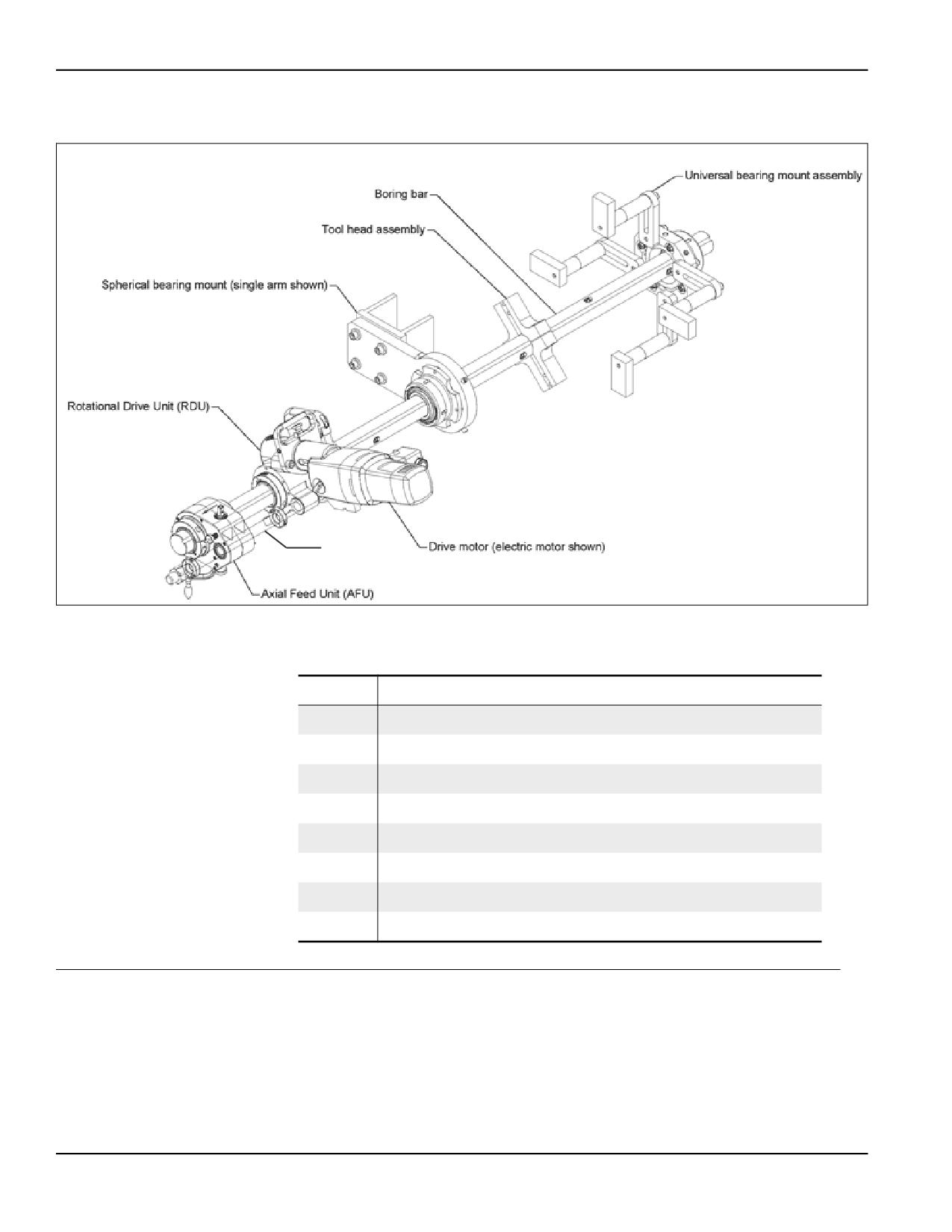
Figure 2-1 shows the BB4500-BB5000 major components, defined in Table 2-1.
5
4
3
2
1
7
6
Leadscrew
8
FIGURE 2-1. BB4500-BB5000 COMPONENTS WITH EIBENSTOCK MOTOR (BB5000 SHOWN)
TABLE 2-1. BB5000 COMPONENT IDENTIFICATION
Number
Component
1
Rotational drive unit (RDU)
2
Spherical bearing mount (single arm shown)
3
Tool head assembly
4
Boring bar
5
Universal bearing mount assembly
6
Drive motor (electric Eibenstock motor shown)
7
Leadscrew
8
Axial feed unit (AFU)
2.1
BB4500 FEATURES
The BB4500’s modular design and diverse setup options offer innovative solutions
to difficult on-site maintenance problems. The BB4500 is designed for on-site
repair and servicing of heavy equipment at chemical plants, public utilities, mills,
mines, power stations, fluid transmission, and distribution systems.
Page 12
BB4500-BB5000 Operating Manual
2.2
BB5000 FEATURES
The BB5000 can be used easily in small workspaces. CLIMAX’s mounting com-
ponents provide the flexibility to handle tough boring jobs. The BB5000's through-
bar design allows you to mount the rotational drive and feed unit anywhere along
the bar. This flexibility means the BB5000 will complete your job where others
would not even fit.
This portable boring machine is a versatile tool. Its broad array of accessories
enables the BB5000 for use in blind boring, line boring, drilling, facing, threading,
valve repair, and trepanning. A special interface kit allows quick attachment and
precise alignment of a welder to the BB5000’s mounting fixtures. CLIMAX also
offers the industry’s broadest range of electric, hydraulic, and pneumatic power
options for added flexibility.
The BB5000 is a highly configurable machine with many options and accessories,
though this manual only covers the basic assembly components. If a specific
machine application requires accessories, contact CLIMAX for more information.
This manual also describes the operation (Section 4 on page 51) and maintenance
(Section 5 on page 57) of your BB5000. The machine is designed for on-site main-
tenance of heavy-duty industrial equipment. All parts meet CLIMAX’s strict qual-
ity standards. For maximum safety and performance, read the entire manual before
operating the machine.
2.3
COMPONENTS
The BB4500 and BB5000 have the following components.
2.3.1
Rotational drive unit
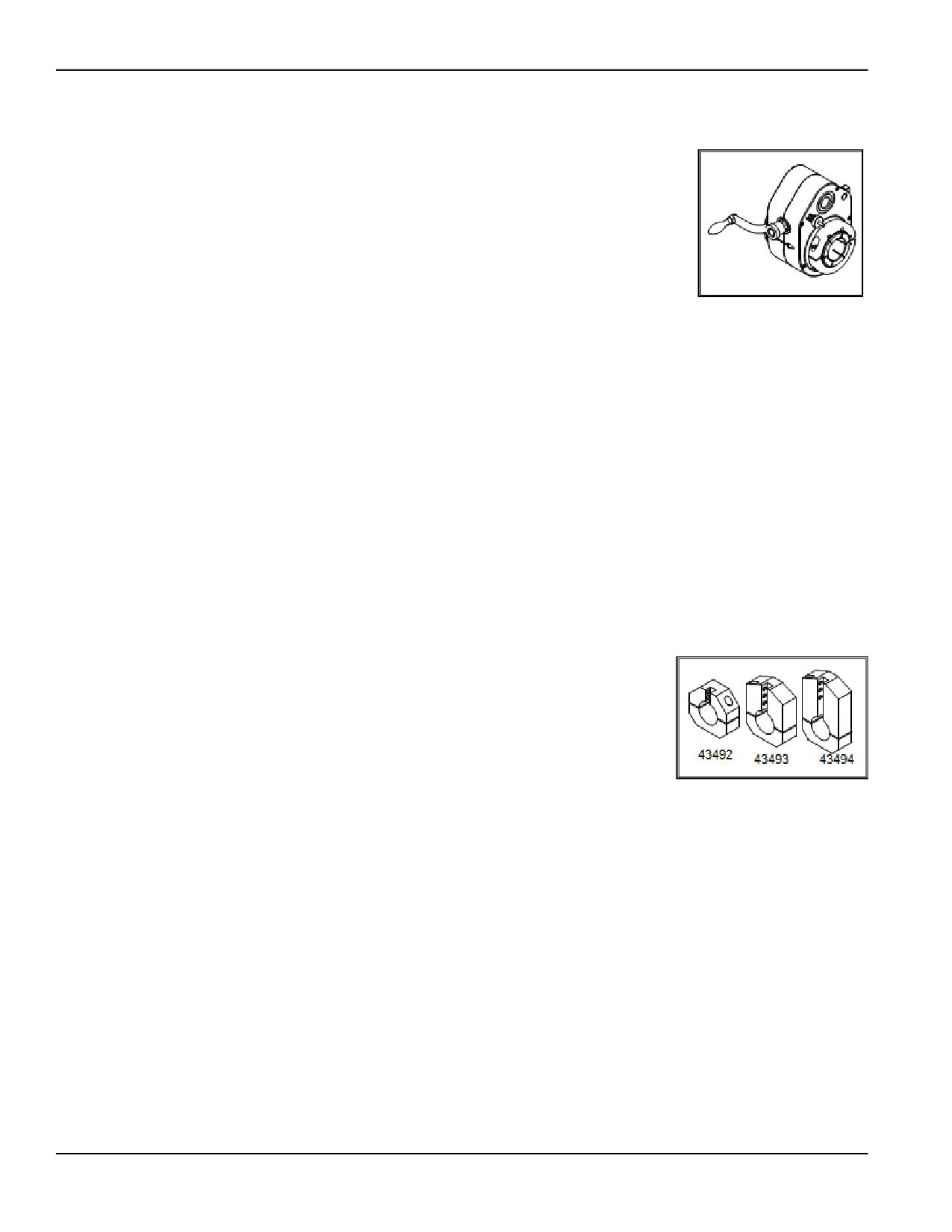
The RDU with sealed lubrication has worm gear reduction
and may be mounted anywhere along the bar. A key within
the collet drives the boring bar. The clamp ring holds the
RDU to the spherical bearing mounting bracket. A clamp col-
lar provides a snug, sliding fit between the RDU and the bar,
or it may be clamped tight for facing operations.
FIGURE 2-2. RDU
P/N 92974, Rev. 3
Page 13
2.3.2
Axial feed unit
The AFU is held in place by two clamp collars and may
be secured in any position along the bar. It travels with
the bar and tool head axially along a fixed leadscrew.
Select the feed direction by shifting the feed shaft posi-
tion (see Section 3.4.1 on page 40 for more information).
FIGURE 2-3. AFU
2.3.3
Leadscrew
The fixed leadscrew may be mounted either to the RDU or to the axial leadscrew-
mounting block.
For the BB4500, standard leadscrews have 12" (305 mm) or 24" (610 mm) of
travel.
For the BB5000, standard leadscrews have 12" (305 mm), 24" (610 mm), or 36"
(914 mm) of travel.
Other lengths are available to suit your requirements. Contact CLIMAX for more
information.
2.3.4
BB4500 tool heads
For the BB4500, the split-body tool heads may be
clamped anywhere along the bar. The set of three tool
heads bore 4-10" (102-254 mm) diameter. The tool
heads hold tool bits that are 0.5" (12 mm) square.
Boring heads accept 0.5" (12 mm) square tool bits and
machine sizes that are 4-10" (102-152 mm), 6-8"
FIGURE 2-4. BB4500 TOOL HEADS
(152-203 mm), and 8-10" (203-254 mm) in diameter.
They are compatible with either high-speed steel
(HSS) or carbide-tipped tool bits.
For boring diameters less than 4" (102 mm), use the broached tooling holes in the
bar. For boring diameters less than 2" (51 mm), use the small boring option.
Blank and pre-ground 0.5" (12 mm) tool bits are available for the slotted boring
heads.
2.3.5
BB5000 tool heads
For the BB5000, the split-body tool heads may be clamped anywhere along the
bar.
Page 14
BB4500-BB5000 Operating Manual
Two sets of tool heads are available:
• One set of five tool heads bore 4.5-12"
(114-305 mm) diameter.
• The optional large boring head features a
split-body mounting hub and two sets of tool
arms that bore 12-24" (305-610 mm) diam-
eter.
FIGURE 2-5. BB5000 TOOL
HEADS
Tool bits are 1/2" (12 mm) square. Other tool head
options are discussed in Section 3.3.2 on page 35.
2.3.6
BB4500 boring bar
Standard BB4500 bars are 1.75" (44 mm) in diameter and are available in lengths
from 4-12 ft (1.2-3.66 m) in 24" (610 mm) increments. Contact CLIMAX for bars
of other lengths and diameters.
All bars have 0.5" (12 mm) square tool bit mounting holes spaced at 10" or 6" (254
or 152 mm) intervals. Contact CLIMAX for custom hole spacing patterns.
Do the following to determine the bar length required (see Figure 2-14 on page
26):
1. Determine the workpiece overall dimension + stroke + 27" (686 mm).
2. Round up to the next 24" (610 mm) increment.
2.3.7
BB5000 boring bar
Standard BB5000 bars are 2.25" (57 mm) in diameter and are available in lengths
from 4-12 ft (1.2-3.66 m) in 24" (610 mm) increments. Contact CLIMAX for bars
of other lengths and diameters.
All bars have 0.5" (12 mm) square tool bit mounting holes spaced at 10" or 6" (254
or 152 mm) intervals. CLIMAX offers a drill jig with a tool sleeve kit for cutting
intermediate tool bit holes for special applications. Contact CLIMAX for custom
hole spacing patterns.
Do the following to determine the bar length required (see Figure 2-14 on page
26):
1. Determine the workpiece overall dimension + stroke + 27" (686 mm).
2. Round up to the next 24" (610 mm) increment.
P/N 92974, Rev. 3
Page 15
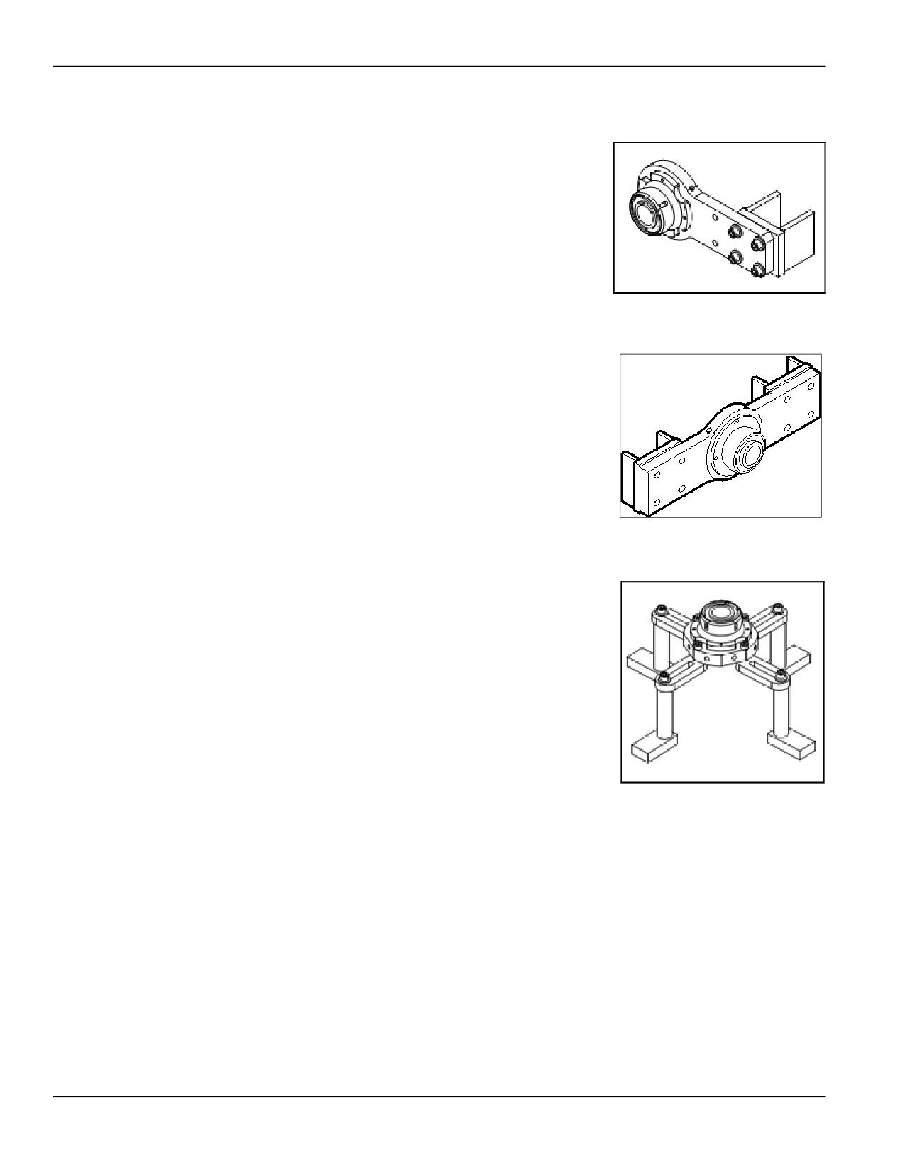
2.3.8
Spherical bearing mounts
The spherical bearing mount support brackets hold
the bar and machine in place during operation.
Each bracket includes a spherical self-aligning
bearing for quick, accurate setup. Spacer plates
may be tack welded or clamped to the workpiece to
secure the brackets in place.
FIGURE 2-6. SINGLE-ARM SPHERICAL
BEARING MOUNT
These brackets are available in single-arm, double-
arm, and universal styles. The universal mount
may also be turned into an inside diameter (ID)
mount with the purchase of an optional set of jack-
ing bolts.
FIGURE 2-7. DOUBLE-ARM SPHERICAL
BEARING MOUNT
Double-arm spherical bearing mounting brackets
are better for those applications requiring extra sup-
port, such as when boring holes exceed 8" (203 mm)
in diameter.
FIGURE 2-8. UNIVERSAL SPHERICAL
BEARING MOUNT
Page 16
BB4500-BB5000 Operating Manual
2.4
CONTROLS
Table 2-2 shows the power options available for the BB4500-BB5000. Please note
that only the BB5000 has the servo drive option.
TABLE 2-2. POWER OPTIONS
Power type
RPM1 range
Power
Reference
10 hp HPU2: 0 - 246 RPM at
60 Hz mains power
Section 2.4.1 on
Hydraulic
10 hp (7.4 kW)
page 18
10 hp HPU: 0 - 200 RPM at
50 Hz mains power
Section 2.4.3 on
Electric
8 - 160 RPM
3.35 hp (2.5 kW)
page 21
Section 2.4.4 on
Pneumatic
0 - 120 RPM
3.0 hp (2.2 kW)
page 24
Servo
Section 2.4.2 on
3 - 230 RPM
4.7 hp (3.5 kW)
(BB5000 only)
page 19
1. Revolutions per minute (RPM)
2. Hydraulic power unit (HPU)
For more information about using the BB4500-BB5000 controls, see Section 3.5
on page 43.
The RDU used with hydraulic, pneumatic, and electric drives has a 4:1 gear reduc-
tion. The servo drive uses 12:1 gear reduction.
TABLE 2-3. TEST DATA
Material:
A-36 (mild steel)
Bore diameter:
23" (584.2 mm)
Tool bit:
High speed steel (HSS)
Bearing spacing:
22" (558.8 mm)
Bar speed:
30 - 40 RPM
Depth of cut:
100” (2,540 mm)
Feed rate:
0.003" (0.076 mm) per revolution
Length of cut:
2” (50.8 mm)
TABLE 2-4. SETUP CONES
Range
Standard
2.75-12” (70-305 mm)
Optional
1.375-5” (34.9-127 mm)
P/N 92974, Rev. 3
Page 17
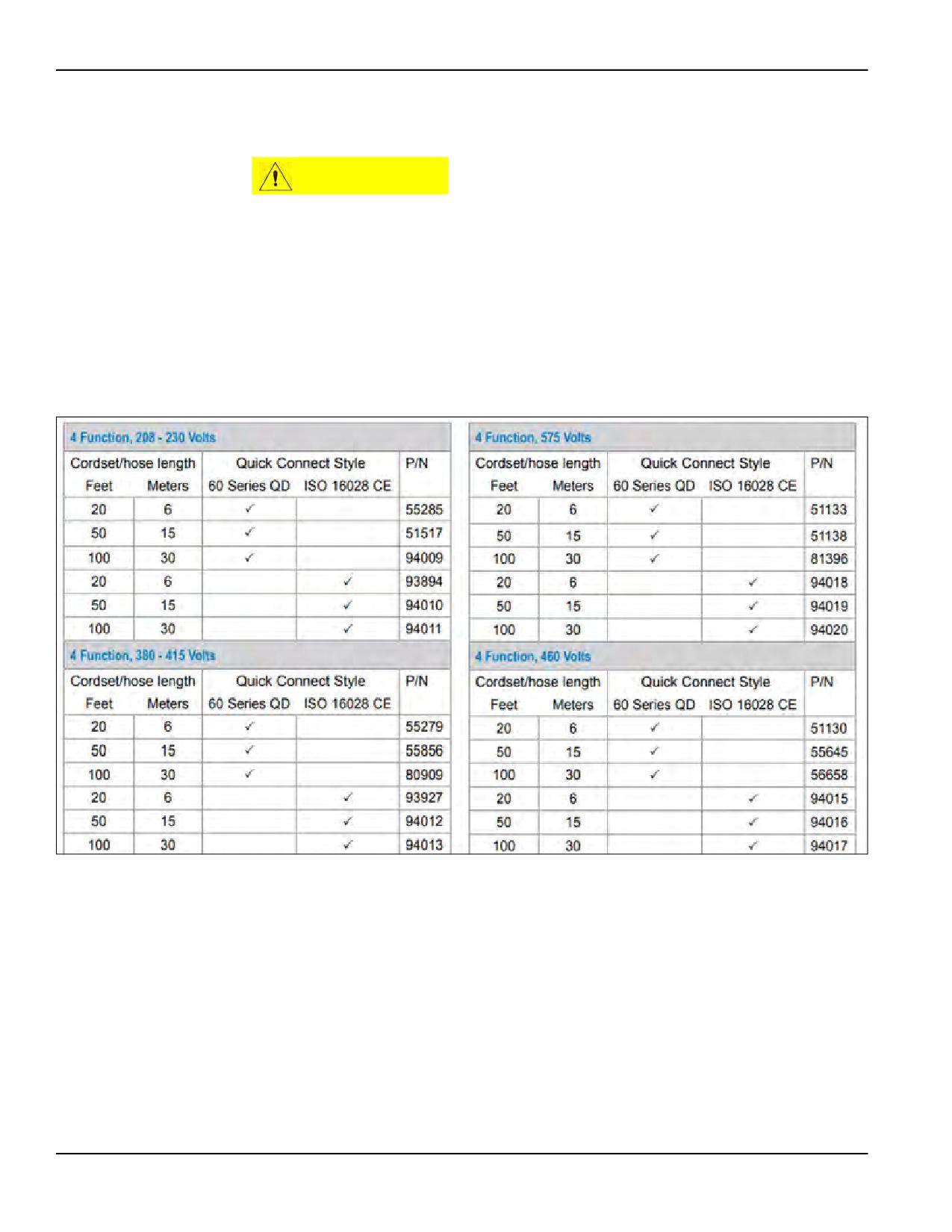
2.4.1
Hydraulic power unit and hydraulic motors
CAUTION
Operating the hydraulic power unit (HPU) for extended periods of time
without connecting the hydraulic motor will overheat the system and
may damage the pump.
The high-torque, low-speed hydraulic motor mounts directly to the RDU. To
reverse the bar rotation direction, switch the hydraulic hoses at the motor or at the
HPU.
Table 2-5 on page 18 shows the available HPUs and their specifications.
TABLE 2-5. AVAILABLE HPU SPECIFICATIONS
If using an HPU not supplied by CLIMAX, the hydraulic requirement is 10 gpm at
2,000 psi (37.85 lpm at 138 bar).
Hydraulic motors with different displacement ratings are available. Please note the
following:
• If the HPU runs on 50 Hz, it produces a maximum rate of 8.3 gpm.
• If the HPU runs on 60 Hz, it produces a maximum rate of 10 gpm.
Page 18
BB4500-BB5000 Operating Manual
Refer to the correct “Maximum bar RPM” column in Table 2-6 for hydraulic motor
performance.
TABLE 2-6. HYDRAULIC MOTOR SPECIFICATIONS
Maximum bar RPM
Part number
Part number
Torque at
for motors with
for motors with
Motor capacity
8.36 gpm
10 gpm (37.9
bar
60 series QD
ISO 16028 QD
(31.5 L/min)1
L/min)2
fittings
fittings
92 ft-lbs
2.2 inch3 (36 cm3)
204
246
39837
65384
(124.7 Nm)
159 ft-lbs
3.6 inch3 (59 cm3)
124
150
39843
63425
(215.6 Nm)
270 ft-lbs
5.7 inch3 (93.4 cm3)
76
92
39844
63429
(367 Nm)
342 ft-lbs
7.3 inch3 (119.6 cm3)
60
73
39845
69434
(463.7 Nm)
417 ft-lbs
8.9 inch3 (145.8 cm3)
49
60
39846
69435
(565.4 Nm)
478 ft-lbs
11.3 inch3 (185.2 cm3)
40
49
43451
69436
(648.1 Nm)
652 ft-lbs
14.1 inch3 (231.1 cm3)
31
38
39847
39847
(884.0 Nm)
764 ft-lbs
17.9 inch3 (293.3 cm3)
24
30
43452
69439
(1,035.8 Nm)
1. With 50 Hz mains power.
2. With 60 Hz mains power.
2.4.2
BB5000 servo motors
NOTICE
Never disconnect any cable from this machine without first turning off
the mains disconnect switch. Interrupting the connection between the
servo amplifier and the servo motor while they are energized may
damage the servo amplifier, even if the motor is stopped. Failure to
comply with this warning will void the warranty on the control system.
P/N 92974, Rev. 3
Page 19
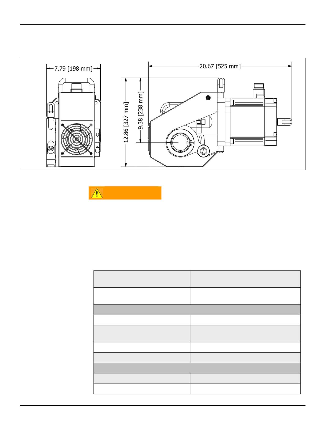
The 4.7 hp servo motor with a 12:1 worm gear reduction RDU provides quiet,
reversible and extreme torque for operating the BB5000.
FIGURE 2-9. BB5000 SERVO DRIVE DIMENSIONS
WARNING
Handle cables carefully. Do not pull on them, step on them, or allow
them to be kinked. Pelikan cases are water resistant, not water-proof.
Do not turn on the power unless all cables are plugged in. Do not
unplug cables unless disconnected from mains power.
Servo drives for the BB5000 are available in 230V (16 amps) or 460V (8.5 amps).
TABLE 2-7. BB5000 SERVO MOTOR SPECIFICATION
200V-240V, 50/60 Hz dual-rated, 16 amp,
Input power for the 230V system:
3-phase
380V-480V, 50/60 Hz dual-rated, 8.5 amp,
Input power for the 460V system:
3-phase
Bar
Bar speed:
3-230 RPM
Bar rated torque (continuously
3-167 RPM: 147.9 ft-lbs (200.4 Nm)
running):
Bar maximum torque:
3-230 RPM: 443.7 ft-lbs (601.6 Nm)
Rotation:
Variable speed and reversible
Motor
Manufacturer:
Mitsubishi
Speed rated continuous:
2,000 RPM
Page 20
BB4500-BB5000 Operating Manual
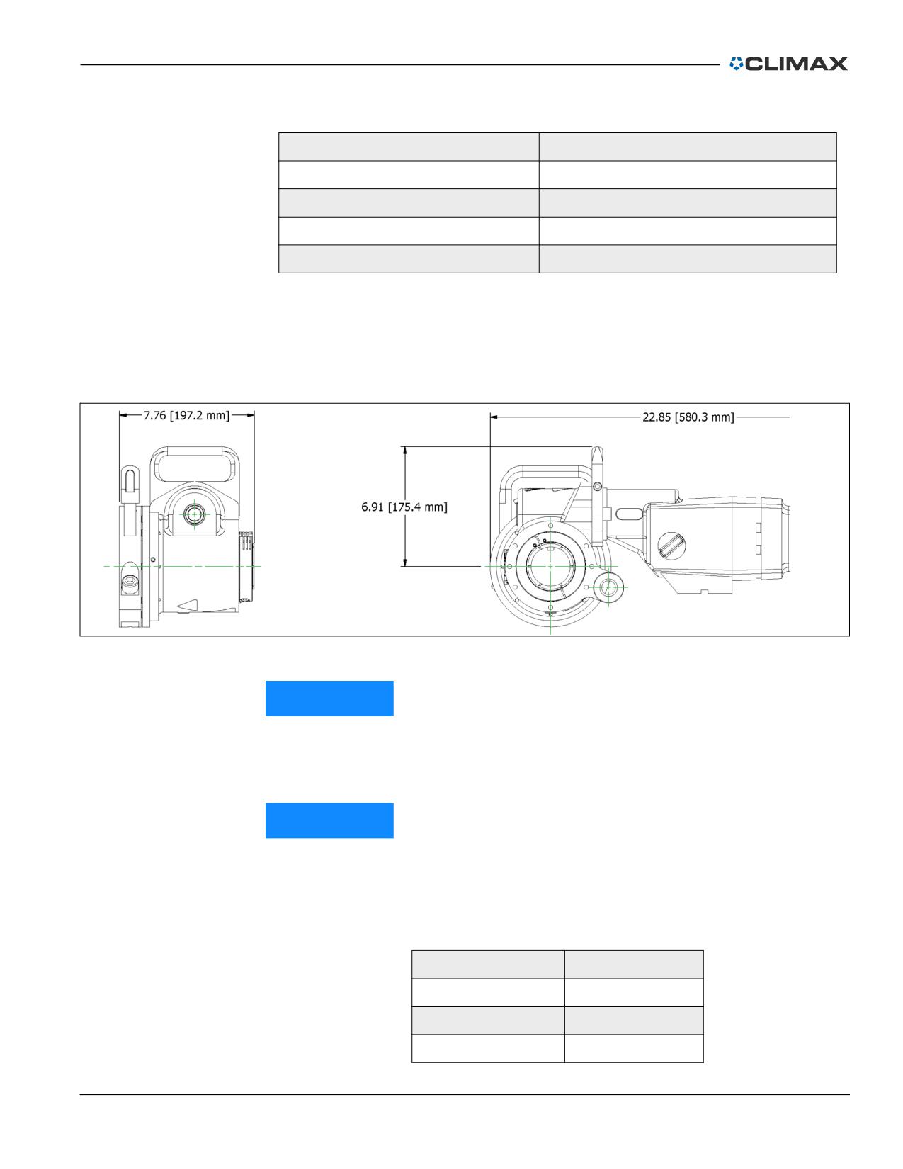
TABLE 2-7. BB5000 SERVO MOTOR SPECIFICATION (CONTINUED)
Speed maximum:
3,000 RPM
Speed permissible instantaneous:
3,450 RPM
Nominal rated full load hp:
4.7 hp (3.5 kW)
Motor torque rated:
12.3 ft-lbs (16.7 Nm)
Motor torque maximum:
37.0 ft-lbs (50.1 Nm)
2.4.3
Electric motor
Two electric versions of the BB5000 are available, as described in Table 2-9 on
page 22. The motor has an integrated rotation reverse switch, while the pendant
controller has an off/off switch, emergency stop, and a speed control knob.
FIGURE 2-10. RDU AND EIBENSTOCK MOTOR DIMENSIONS
NOTICE
The second-generation Eibenstock motor is incompatible with the third-
generation RDU. The second-generation Eibenstock motor requires the
fourth-generation RDU.
NOTICE
Table 2-8 shows the four mains power plugs for the control box that
CLIMAX offers. If the plug needed is not included in Table 2-8, the end
user must cut off the factory-installed plug and install their own.
TABLE 2-8. CONTROL BOX
120V Controller:
L5-30P twist-lock
120V Controller:
ISO 309/CEE17
230V Controller:
CEE 7/7 Schuko
230V Controller:
6L-15P twist-lock
P/N 92974, Rev. 3
Page 21
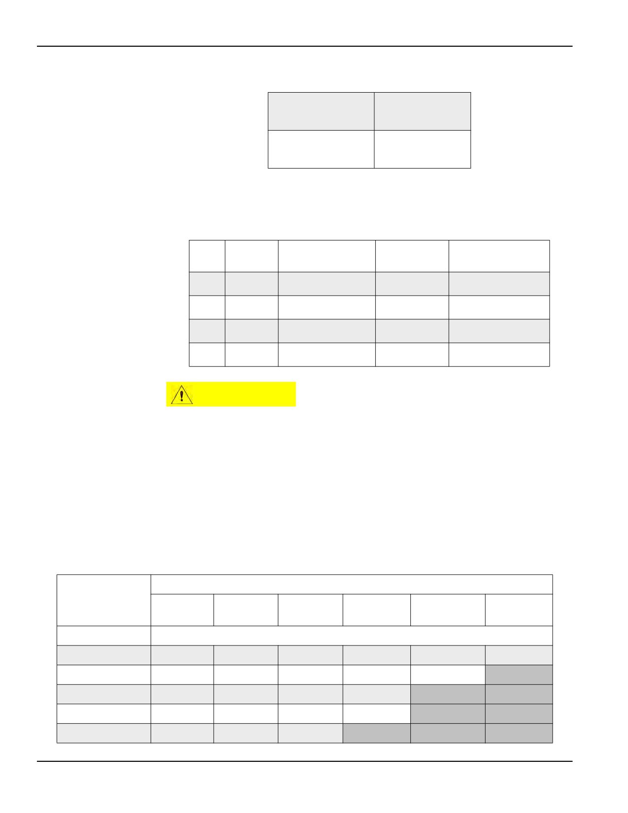
TABLE 2-9. POWER RATING
3.35 hp (2.5 kW)
120V motor:
20 Amps 60 Hz
3.35 hp (2.5 kW)
230V motor:
10.5 Amps 60 Hz
Both motors have a four-speed gearbox for maximum versatility. Table 2-10 speci-
fies the operating range for each gear.
TABLE 2-10. SPEED RANGE AND TORQUE PER GEAR
Rated bar
Gear
Knobs
RPM range
Bar torque
speed
1
● ●
8.0-23.0 RPM
20 RPM
470 ft-lb (637 Nm)
2
● ●●
12.5-35.5 RPM
30 RPM
300 ft-lb (407 Nm)
3
●● ●
35.5-101.0 RPM
90 RPM
105 ft-lb (142 Nm)
4
●● ●●
56.5-160.0 RPM
142.5 RPM
65 ft-lb (88 Nm)
CAUTION
Before shifting gears, remove the cutting load from the motor and stop
the motor rotation. Shifting gears while the machine is under load could
damage the motor and gearbox components.
CLIMAX’s portable machine tools require a three-wire extension cord. Extension
cords of inadequate wire size may cause a significant drop in mains voltage with a
consequent loss of power.
As the distance from the supply outlet increases, heavier gauge extension cords are
required (see Table 2-11).
TABLE 2-11. RECOMMENDED WIRE GAUGE FOR EXTENSION CORDS
Cord length
25 feet
50 feet
75 feet
100 feet
150 feet
200 feet
(7.6 m)
(15.2 m)
(22.9 m)
(30.5 m)
(45.7 m)
(61 m)
Nameplate amps
Minimum wire gauge
0-5.0
16
16
16
14
12
12
5.1-8.0
16
16
14
12
10
8.1-12.0
14
14
12
10
12.1-15.0
12
12
10
10
15.1-20.0
10
10
10
Page 22
BB4500-BB5000 Operating Manual
Table 2-12 and Table 2-13 list the service parts for both motors.
TABLE 2-12. 120V SERVICE PARTS
Part number
Description
Quantity
83595
Rotor complete
1
82698
Carbon brush
2
83593
PCB / circuit board
1
83594
Stator complete
1
TABLE 2-13. 230V SERVICE PARTS
Part number
Description
Quantity
90776
Rotor Complete
1
90778
Brush Holder
2
85088
Carbon Brush
2
83591
Anti Parasite Condenser
1
85089
PCB / Circuit Board
1
82699
Cap
1
90779
Stator Complete
1
83601
Grooved Ball Bearing 6201 LUZ
1
90780
Locking Ring 32x1,2
1
83602
Shaft Seal Ring 15x21x3 KEIV
1
90238
Work Spindle
1
90781
Shaft Seal Ring 30x42x7
1
90782
Grooved Ball Bearing 6005 2RS
1
90783
O-ring 106x2
1
85494
Switch Button Long
1
85493
Switch Button Short
1
90784
Connector Socket
1
90785
Insert
1
90786
Screw 3x10
4
87279
Reversing switch
1
90787
Connector Pin 2,5 mm2
3
90788
Connector Pin 0.75 mm2
2
P/N 92974, Rev. 3
Page 23
2.4.4
Air motor
The 3 hp (2.24 kW) air motor is reversible and operates
under the specifications listed in Table 2-14.
TABLE 2-14. CONTROL BOX
Air pressure required:
90 psi (6.2 bar)
Air flow required:
95 ft3/min (2.7 m3/min)
FIGURE 2-11. AIR MOTOR
The available air motor assemblies produce boring bar
speeds and torques listed in Table 2-15.
TABLE 2-15. BAR RPM AND TORQUE AT MAXIMUM HP
Air motor part number
Bar RPM
Torque
28614
120 RPM
115 ft-lb (156 Nm)
28697
57 RPM
234 ft-lb (318 Nm)
The assembly includes the RDU mounting flange and associated hardware. For a
complete air-powered system, order an air motor assembly and connection pack-
age. The air connection package contains an air filter and lubricator, and hoses
with quick disconnect fittings.
CAUTION
To maintain the air motor and avoid invalidating your warranty, always
route incoming air through the pneumatic conditioning unit (PCU).
2.4.5
Pneumatic conditioning unit
The PCU (shown in Figure 2-12 on page 25) provides clean dry air and lubrication
to the air motor. Install the PCU in the air supply circuit immediately before the
BB4500 or BB5000.
WARNING
Always stop the machine and lock out/tag out the PCU before making
adjustments to controls or machine components. Failure to follow this
safety precaution may result in severe injury.
Page 24
BB4500-BB5000 Operating Manual
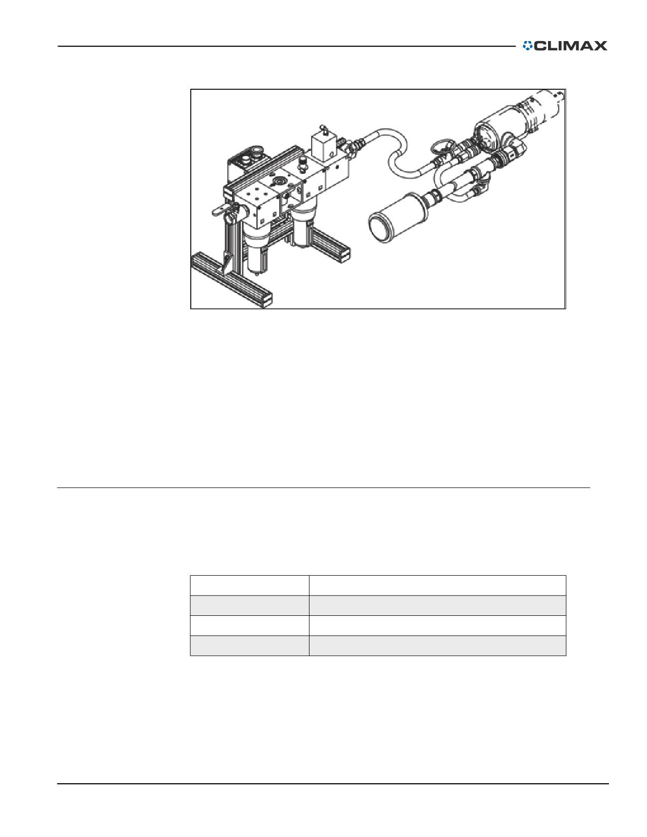
FIGURE 2-12. PNEUMATIC CONDITIONING UNIT
Emergency shutdown
To stop machine operation immediately, press the emergency stop button on the
PCU.
Before restarting the BB4500-BB5000, check the following:
1. Close the speed adjustment valve.
2. Pull the emergency stop button up.
3. Press the START button (repeat step 1 if necessary).
2.5
DIMENSIONS
Table 2-16 shows the BB4500 and BB5000 dimensions.
TABLE 2-16. DIMENSIONS
Component
Width x diameter x height
Machine
52.5” x 27” x 16.5” (1,334 x 686 x 419 mm)
72" (1,828.8 mm) bar
74.5” x 6.5” x 7” (1,892 x 165 x 178 mm)
HPU
49.5” x 30.5” x 41” (1,257 x 775 x 1,041 mm)
The following figures show the BB4500-BB5000 machine and operating dimen-
sions.
P/N 92974, Rev. 3
Page 25
TABLE 2-17. BB4500-BB5000 BORING BAR DIMENSION IDENTIFICATION
Number
Component
1
Stroke
2
Workpiece: distance between outer edges of the workpiece = X
2.6
SPECIFICATIONS
TABLE 2-18. SUB-COMPONENT MASS
Component
Mass in lbs (kg)
Motor:
43 lbs (20 kg)
Adapter assembly (P/N 51536):
10 lbs (5 kg)
Rotational drive unit (P/N 53165):
31 lbs (14 kg)
Total for motor, adapter assembly and RDU:
85 lbs (39 kg)
Pendant:
4 lbs (2 kg)
HPU - 10 HP:
695 lbs (315.2 kg)
Machine total weight (including single arm
444 lbs (201 kg)
mounts, setup cones, and hydraulic motor):
Approximate boring bar ship weight (including
1.48 lbs/inch
the metal shipping container):
(0.264 kg/cm)
TABLE 2-19. BORING SPECIFICATIONS
Component
BB4500 range
BB5000 range
Boring bar diameter (standard):
1.75" (45 mm)
2.25" (57 mm)
1.75" (45 mm)
Boring bar diameter (optional):
1.25" (32 mm)
1.25" (32 mm)
Boring diameter (standard):
2-10" (51-254 mm)
2.5-12" (64-305 mm)
Boring diameter (optional):
1.5-5" (38-127 mm)
1.375-24" (35 - 610 mm)
Boring stroke (standard):
12" (305 mm)
12" (305 mm)
24 (610 mm)
Boring stroke (optional):
36" (914 mm)
36" (914 mm)
P/N 92974, Rev. 3
Page 27
2.6.1
Electrical specifications
CLIMAX electrical equipment is suitable for use in the physical environment and
operating conditions specified below. When the physical environment or the oper-
ating conditions are outside those specified, consult CLIMAX before putting the
electrical equipment into service.
TABLE 2-20. ELECTRICAL SPECIFICATIONS
Mains voltage (AC):
±10% of nominal
Mains frequency (AC):
±1% of nominal
10% of RMS volts
Mains harmonics:
2nd through 30th harmonic
Voltage imbalance (3-phase supplies):
2% maximum
200% of nominal
Voltage impulses:
1.5 milliseconds (ms) maximum duration
Voltage interruption:
3 ms maximum with 1 second between
Voltage dip (brownout):
20% of peak volts for 1 second maximum
Voltage supplied from batteries:
±10% of nominal
Voltage interruption (DC):
5 ms maximum
Ambient temperature (operating):
41-104°F (5-40°C)
Ambient temperature (transport and
-13-131°F (-25-55°C)
storage):
Relative humidity:
20-95% non-condensing
Altitude:
6,600 ft (2,000 m)
IP54 environment except for some motors
Contaminants:
and slip ring assemblies that are IP 20
Not greater than that listed on the controls
Available fault current:
nameplate
Vibration
Pushbuttons:
5g at 5-300 Hz
Relays, contactors, and breakers:
2g at 5-300 Hz
Touchscreen HMI:
1g at 9-150 Hz
Servo amplifiers and PLC:
1g at 9-150 Hz
Physical shock (impact)
Pushbuttons:
30g for 18ms
Relays, contactors, and breakers:
6g for 11ms
Touchscreen HMI:
15g three times in X, Y, and Z
Servo amplifiers and PLC:
1g three times in X, Y, and Z
Page 28
BB4500-BB5000 Operating Manual
2.7
ITEMS REQUIRED BUT NOT SUPPLIED
The only item required but not supplied in your CLIMAX product kit is a welder
to weld on the tack plate when mounting the bearings onto the workpiece.
P/N 92974, Rev. 3
Page 29
This page intentionally left blank
Page 30
BB4500-BB5000 Operating Manual
3
SETUP
IN THIS CHAPTER:
3.1 RECEIPT AND INSPECTION
- - - - - - - - - - - - - - - - - - - - - - - - - - - - - - - - - - - - -
-31
3.2 LIFTING AND RIGGING - - - - - - - - - - - - - - - - - - - - - - - - - - - - - - - - - - - - - - - -
-32
3.3 MACHINE ASSEMBLY - - - - - - - - - - - - - - - - - - - - - - - - - - - - - - - - - - - - - - - -
-32
3.3.1 BAR AND MOUNTING BRACKET ASSEMBLY
- - - - - - - - - - - - - - - - - - - - - - - - - - -
-33
3.3.2 TOOLING AND TOOL HEAD ASSEMBLY
- - - - - - - - - - - - - - - - - - - - - - - - - - - - -
-35
3.3.2.1 PLACING THE TOOL BIT INTO THE BAR - - - - - - - - - - - - - - - - - - - - - - - - - -
-36
3.3.2.2 PLACING THE TOOL HEAD ONTO THE BORING HEAD - - - - - - - - - - - - - - - - - - - - -36
3.3.3 RDU AND AFU ASSEMBLY - - - - - - - - - - - - - - - - - - - - - - - - - - - - - - - - - -
-37
3.4 AXIAL FEED - - - - - - - - - - - - - - - - - - - - - - - - - - - - - - - - - - - - - - - - - - - -
-40
3.4.1 SELECTING THE FEED DIRECTION - - - - - - - - - - - - - - - - - - - - - - - - - - - - - - -
-40
3.4.2 SETTING THE FEED RATE - - - - - - - - - - - - - - - - - - - - - - - - - - - - - - - - - - -
-41
3.4.3 AUTOMATIC FEED STOP
- - - - - - - - - - - - - - - - - - - - - - - - - - - - - - - - - - -
-42
3.5 POWER CONNECTION - - - - - - - - - - - - - - - - - - - - - - - - - - - - - - - - - - - - - - - -
-43
3.5.1 HYDRAULIC MACHINES - - - - - - - - - - - - - - - - - - - - - - - - - - - - - - - - - - - -
-43
3.5.2 BB5000 SERVO DRIVE MACHINE
- - - - - - - - - - - - - - - - - - - - - - - - - - - - - - -
-44
3.5.3 ELECTRICAL MACHINES - - - - - - - - - - - - - - - - - - - - - - - - - - - - - - - - - - - -
-46
3.5.4 PNEUMATIC MACHINES - - - - - - - - - - - - - - - - - - - - - - - - - - - - - - - - - - - -
-46
3.6 BB4500-BB5000 WITH SMALL DIAMETER BARS - - - - - - - - - - - - - - - - - - - - - - - - - - - - -47
This section describes the setup and assembly procedures for the BB4500-BB5000
boring machine.
3.1
RECEIPT AND INSPECTION
Your CLIMAX product was inspected and tested prior to shipment, and packaged
for normal shipment conditions. CLIMAX does not guarantee the condition of
your machine upon delivery.
When you receive your CLIMAX product, perform the following receipt checks:
1. Inspect the shipping containers for damage.
2. Check the contents of the shipping containers against the included invoice
to make sure that all components have been shipped.
3. Inspect all components for damage.
5Contact CLIMAX immediately to report damaged or missing components.
NOTICE
Keep the shipping container and all packing materials for future storage
and shipping of the machine.
P/N 92974, Rev. 3
Page 31
The machine ships from CLIMAX with a heavy coating of LPS 3. The recom-
mended cleaner is LPS PreSolve Orange Degreaser. All parts must be cleaned
before use.
3.2
LIFTING AND RIGGING
WARNING
Do not lift the BB4500-BB5000 boring machine when fully assembled,
as it can weigh up to 444 lbs (201 kg). To prevent serious injury to
yourself and others, always follow the operating procedures outlined in
this manual, your own company rules, and local regulations for heavy
lifting. Serious injury or fatalities can result from improper lifting
methods.
Falling or uncontrolled swinging of machinery can cause serious injury
or be fatal to the operator and bystanders.
3.3
MACHINE ASSEMBLY
A basic setup is described in the following sections, but individual applications
may require different setups based on, but not limited to, the following factors:
• The size of the bore
• The number of bores and bearings
• Distance between the bores
• Distance between the bearings
• Style of bearings (single arm, double arm, universal)
Contact CLIMAX for assistance with a custom application.
The BB4500-BB5000’s through-bar design allows for mounting the rotational
drive unit (RDU) and feed box anywhere along the bar. They do not need to be
mounted next to each other. This allows assembly of the BB4500-BB5000 in very
restricted spaces. Special setup cones are also available to make it easier to center
and stabilize the bar in the workpiece bore.
Exactly attaching and aligning the tack mounting plates is designed to be straight-
forward. The initial fixture mounting may be 5° or more out of alignment. CLI-
MAX’s spherical mounting system enables the BB4500-BB5000 to align perfectly
with the bore.
The BB4500-BB5000 also features four precision alignment screws for precisely
dialing into the center of an existing bore or into a bore that is not exactly true.
The BB4500-BB5000 modular design eliminates the problem of lifting heavy,
bulky, one-piece machines on the job site. The BB4500-BB5000 quickly assem-
bles and disassembles, one component at a time.
Page 32
BB4500-BB5000 Operating Manual
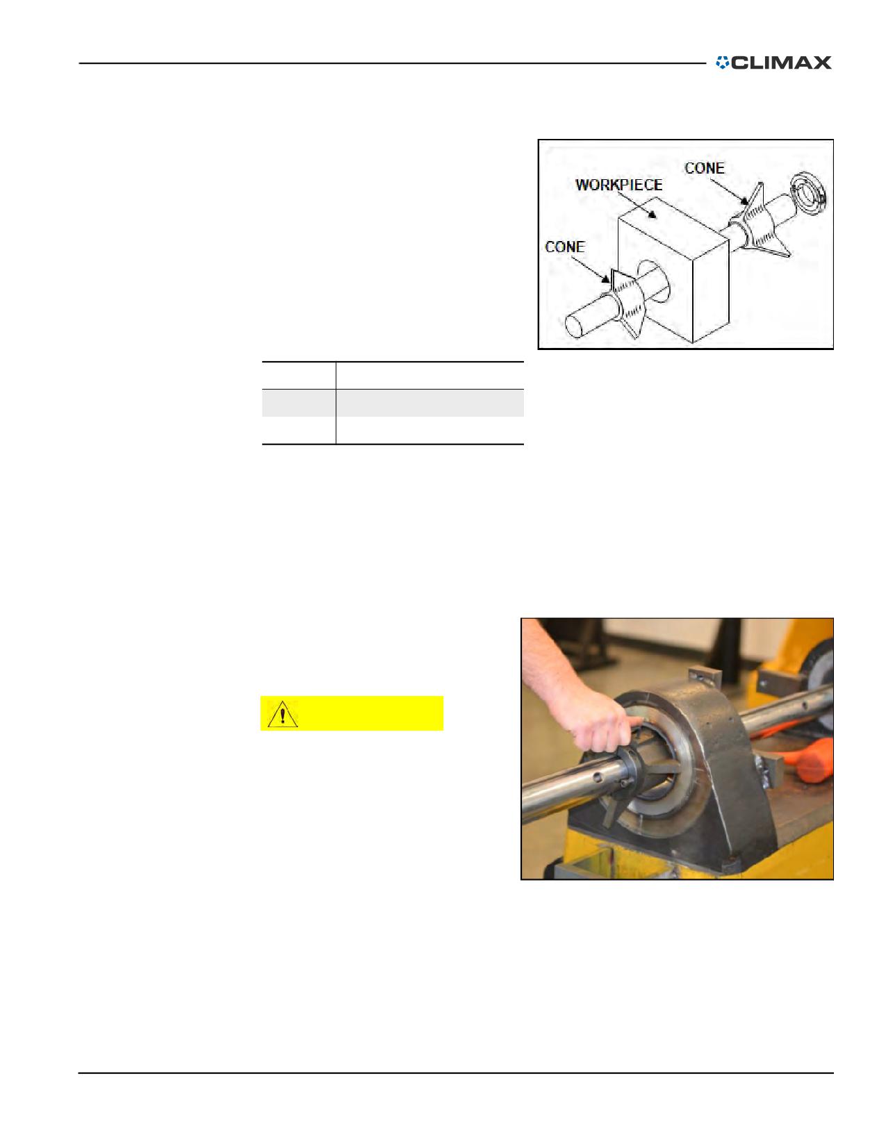
3.3.1
Bar and mounting bracket assembly
To roughly align a CLIMAX boring
1
bar in a workpiece, use centering
2
cones. These cones approximately
center the bar until bearing supports
and brackets are secured with clamps
1
or welds, as appropriate. Cone sets are
in two sizes, cover a wide range, and
are offered as optional equipment
with the BB4500-BB5000.
TABLE 3-1. SETUP CONE IDENTIFICATION
FIGURE 3-1. SETUP CONES
Number
Component
1
Cone
2
Workpiece
The goal is to support the boring bar in place until clamping or welds on tack
plates are completed. Then remove the cones and make precise adjustments to cen-
ter the bar.
Setup cones (optional equipment)
Do the following to install the setup cones:
1. Clean the bore and the boring bar to remove grease, oil, and dirt.
2. Carefully slide the boring
bar through the holes to be
bored (see Figure 3-2).
CAUTION
To avoid bodily injury or bar
damage and to ease setup,
lift heavy loads (bars over
72” [1,829 mm]) using a
sling.
FIGURE 3-2. BORING BAR INSERTION
P/N 92974, Rev. 3
Page 33
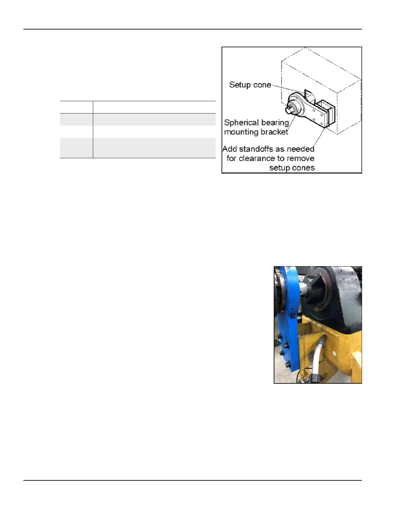
3. Slide a setup cone (or a sub-
stitute device) onto each
end of the bar to center the
bar in the bore.
1
TABLE 3-2. SETUP CONE INSTALLATION IDENTIFICATION
Number
Component
1
Setup cone
2
Spherical bearing mounting bracket
2
Standoffs (add as needed for clearance
3
to remove the setup cones)
3
4. Tighten the set screw to
secure one of the cones.
FIGURE 3-3. SETUP CONE INSTALLATION
5. While pulling on the bar
from the opposing end to seat the first cone, slide the second cone snug into
place. Tighten the set screw.
6. Mount the clamp collar next to one setup cone. Loosen the set screw in the
cone and drive it into the bore using the socket-head jacking screw. Tighten
the set screw in the setup cone to hold it securely in place.
7. Repeat step 3 through step 6 until the cones are seated in the bores and
there is no bar movement.
8. Center the spherical bearings in the mount-
ing brackets by doing the following:
a) Loosen the hex bolts.
b) Adjust the four set screws until the
bearing is centered.
c) Tighten the hex bolts.
FIGURE 3-4. CENTERING THE SPHERI-
CAL BEARINGS
Page 34
BB4500-BB5000 Operating Manual
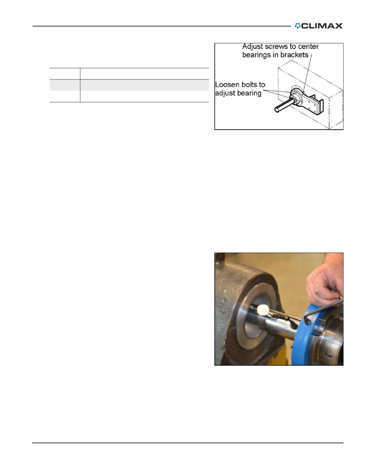
2
TABLE 3-3. SPHERICAL BEARING IDENTIFICATION
Number
Component
1
1
Loosen bolts to adjust bearing
2
Adjust screws to center bearings in brackets
9. Mount the tack weld plates
to the spherical bearing
mounting brackets. If more
FIGURE 3-5. POSITIONING THE SPHERICAL BEARINGS
clearance is required, weld
1" x 1" x 6" (12 mm x 12
mm x 72 mm) the tack weld
blocks to the tack weld mounting spacer plates.
10. Temporarily clamp the bracket assemblies to the workpiece. Leave enough
room to remove the cones after the brackets are welded in place.
11. Check that the setup cones are still securely in position.
12. Securely weld all standoffs and brackets in place.
13. Remove the temporary clamps.
14. Loosen the set screws in the setup cones.
15. Remove the bar from the brackets and remove the setup cones.
16. Carefully reinstall the bar through the mounting brackets.
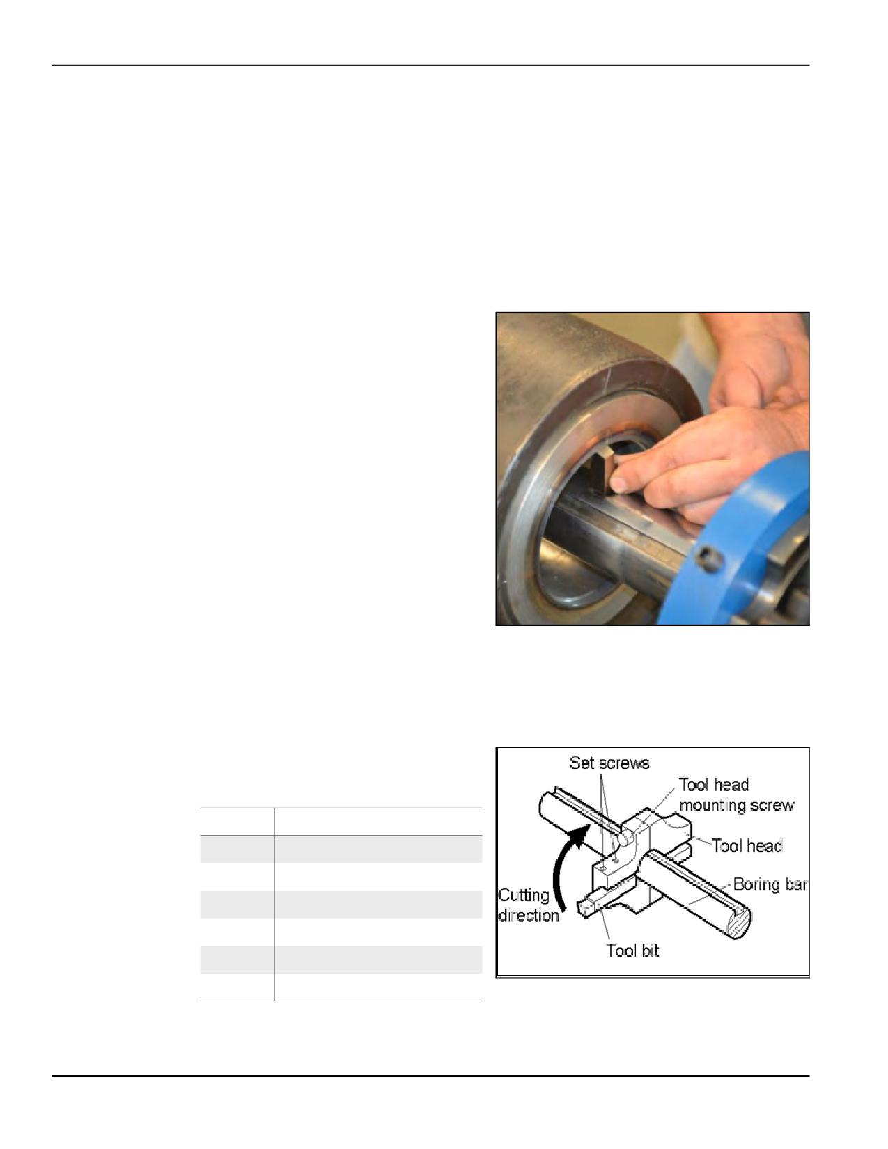
If necessary, precisely align the bar
by doing the following:
1. Loosen the hex bolts hold-
ing the bearing to the
bracket.
2. Attach a dial indicator to
the bar and touch the stylus
to the workpiece ID.
3. Rotating the bar, adjust the
set screws to center the bar.
4. Tighten the hex bolts to
keep the bearing and the bar
in place.
FIGURE 3-6. ALIGNING THE BAR
3.3.2
Tooling and tool head assembly
These machines are designed to cover a wide range of boring applications. The bar
design allows for inserting a tool bit into the bar or clamping a tool head assembly
P/N 92974, Rev. 3
Page 35
onto the bar. This gives you multiple positions of the tool bit. CLIMAX has
designed these so that you can use a variety of tool bit types.
The cutting speed is primarily determined by the hardness of the metal being
machined and the type of tool bit used. Other factors include the power source,
feed and depth of cut, and cooling medium being used.
Generally, carbide cutting tools operate at higher RPM than high-speed steel
(HSS) tools. For more information, see Section 4.2 on page 52.
3.3.2.1
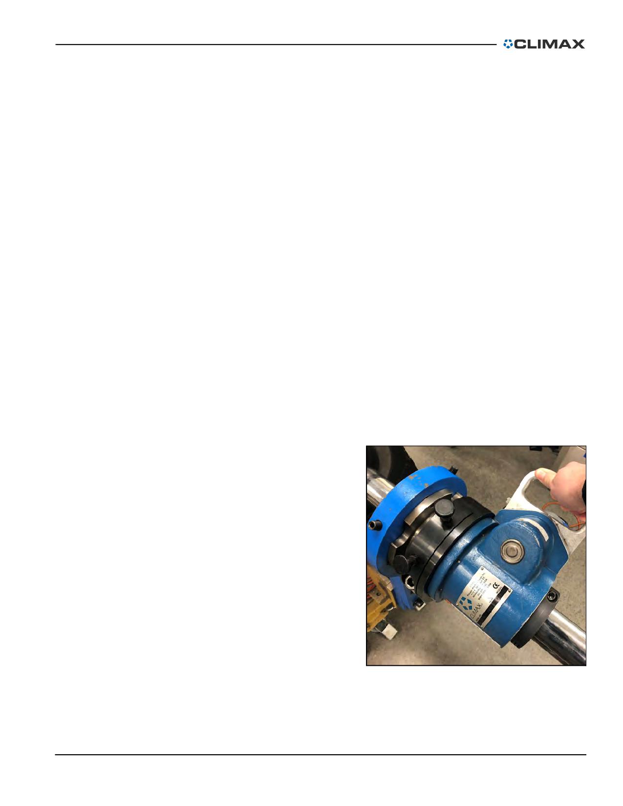
Placing the tool bit into the bar
Do the following to insert the tool
bit into the bar:
1. Retract the set screw that is
located 90° from the tool
slot.
2. Insert the tool bit into the
tool slot so that it slides
freely into the broached
hole (see Figure 3-7).
3. Clamp the tool bit into
place by re-tightening the
set screw.
4. Set the tool bit to the cor-
rect radius for cutting the
required diameter. There
FIGURE 3-7. INSERTING THE TOOL BIT
are multiple ways to set the
desired radius (for instance,
using a bore measuring tool).
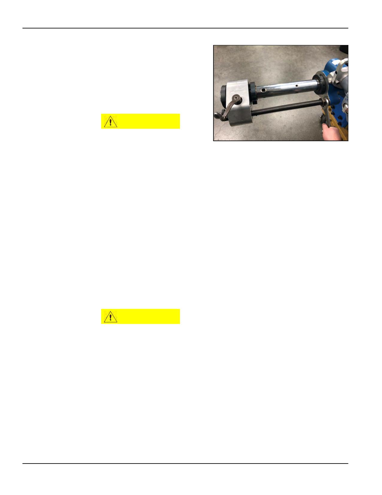
3.3.2.2
Placing the tool head onto the boring head
1
2
TABLE 3-4. TOOL HEAD SETUP IDENTIFICATION
Number
Component
3
1
Set screws
4
2
Tool head mounting screw
6
3
Tool head
4
Boring bar
5
5
Tool bit
6
Cutting direction
FIGURE 3-8. TOOL HEAD SETUP
Page 36
BB4500-BB5000 Operating Manual
Do the following for standard setup, referring to Figure 3-8 on page 36:
1. Using the clamping screw, secure the tool head tightly to the boring bar.
2. Select either a HSS or a brazed carbide tool bit.
3. Position the tool head on the bar with the open side of the tool slot toward
the workpiece in the feed direction.
4. Slide the tool bit into the tool head with the cutting face toward the tighten-
ing screws. This will position the cutting face at or slightly below the cen-
terline.
TIP:
Tool bits are either right-handed or left-handed. This allows for feeding
both directions with the same rotation direction.
5. Use a dial indicator to set the tool bit to achieve the desired depth of cut.
The maximum recommended cutting depth is 0.125" (3 mm). Tighten the
tool bit mounting screws.
TIP:
CLIMAX offers a bore measuring tool specially built for setting the tool
bit height and checking the actual bore diameter. Contact CLIMAX for
more information on this tool.
3.3.3
RDU and AFU assembly
The compact RDU may be placed
anywhere along the bar.
Before beginning set-up, plan the
relationship between the RDU,
motor, and axial feed unit (AFU) to
allow for enough space.
FIGURE 3-9. POSITIONING THE RDU
P/N 92974, Rev. 3
Page 37
The AFU may be set anywhere
along the bar. It is not necessary to
insert the leadscrew directly into
the RDU. The leadscrew may be
screwed into the tack weld block
that may then be welded or
clamped directly to the workpiece.
CAUTION
Take care not to bend or
unduly stress the leadscrew
FIGURE 3-10. POSITIONING THE AFU
during installation.
Do the following:
1. Carefully slide the bar through the spherical mounting bearings.
TIP:
If positioning the AFU between the mounting support brackets, slide it
onto the bar at this point rather than in step 10.
2. Insert the bar into the opposing bearing bracket.
3. Install the RDU onto the bar, positioning it against the spherical bearing
bracket so that one of the spring pins engages one of the slots in the bearing
mount.
4. Tighten the clamp ring to 30 ft-lbs (41 Nm). Slide the bar to see if it is free
to move. If it does not move, the clamp ring is too tight. Loosen the clamp
ring bolt until the bar has some resistance but moves freely.
CAUTION
The clamp ring must be tightened before the machine is turned on. Do
not rely on the spring pins to hold the rotational torque of the machine.
5. Tighten the clamp collar over the collet, as shown in Figure 3-11 on page
39. Turn the collar screw until the collar is snug, but the bar slides easily
through the unit. In most boring applications, this collar can remain loose.
Page 38
BB4500-BB5000 Operating Manual
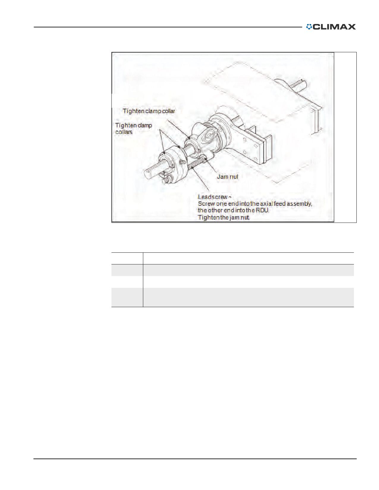
1
2
3
FIGURE 3-11. CLAMP COLLARS ON THE AFU
TABLE 3-5. CLAMP COLLARS INSTALLATION IDENTIFICATION
Number
Component
1
Tighten the clamp collars
2
Jam nut
Leadscrew (Screw one end into the AFU, the other end into the RDU.
3
Tighten the jam nut.)
6. Hold the motor assembly so that the motor shaft is able to slide into the
RDU housing. The key in the motor shaft must align with the keyway in
the main drive worm.
7. Push the motor into the housing until the flange is snug against the drive
housing face.
8. Tighten the mounting screws.
9. Install the leadscrew into the AFU. Check that the jam nut is on the other
end of the leadscrew.
10. Slide the AFU onto the bar, if not already done so to position it between the
mounting support brackets.
11. Thread the leadscrew into the RDU housing. Secure the leadscrew by tight-
ening the jam nut snug against the face of the drive housing.
P/N 92974, Rev. 3
Page 39
12. If mounting the leadscrew away from the RDU, weld the tack weld block
to a fixed object and screw the leadscrew into it. Secure the leadscrew by
tightening the jam nut snug against the face of the tack weld block.
13. Position the AFU and bar to achieve the required feed distance and to place
a tooling hole in the correct position for machining.
14. Tighten the axial feed clamp collar screws to fasten the collar to the bar.
3.4
AXIAL FEED
3.4.1
Selecting the feed direction
The feed direction has three positions:
• Forward
• Neutral
• Reverse
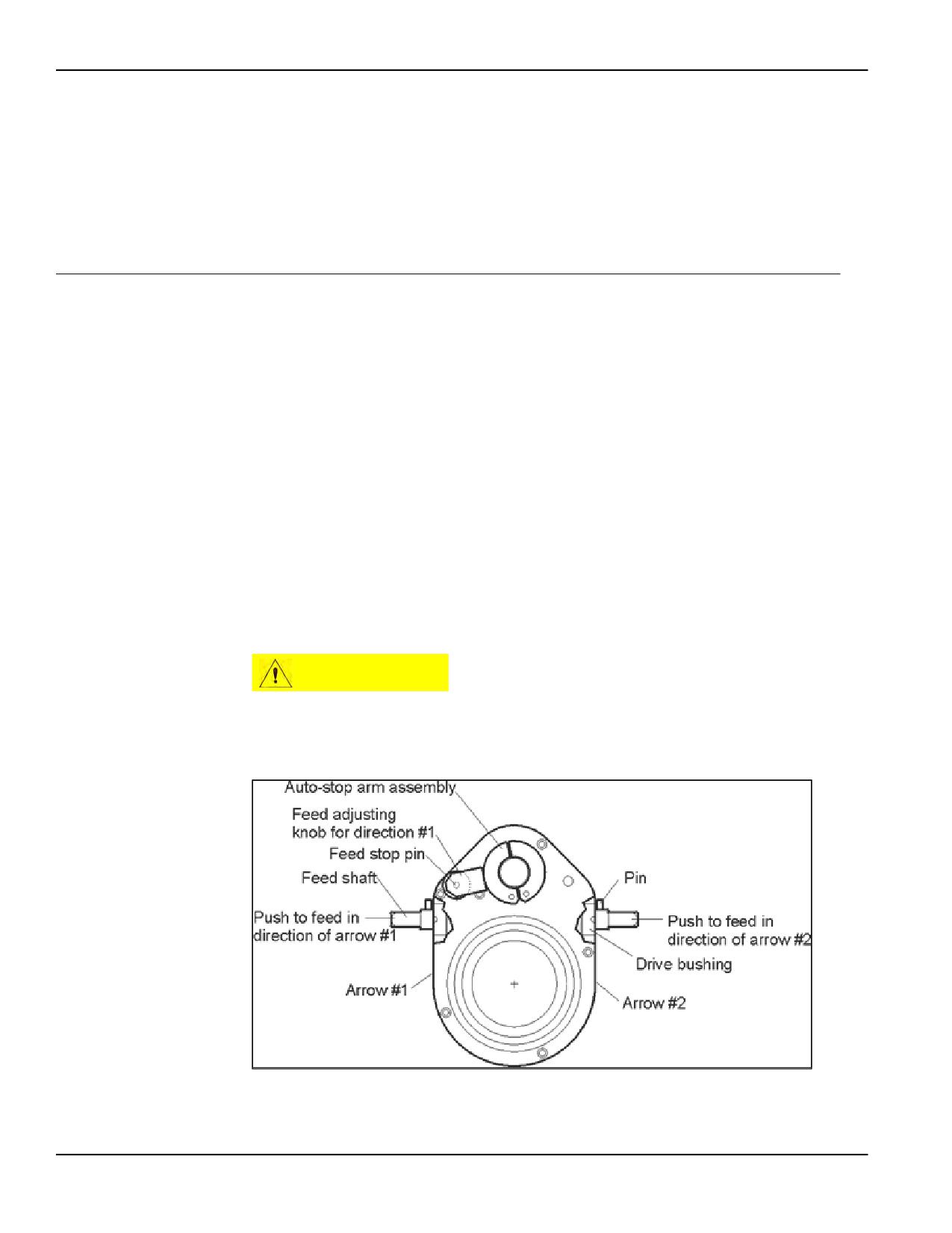
Pushing the three-position feed shaft in on one side or the other will feed in the
direction indicated by the arrow on that side of the body. Check that the engage-
ment pins are fully engaged. The neutral (middle) position is for no feed.
A shaft under load may require a firm bump to disengage.
If the axial feed box fails to feed the tool head, check the shear pins. Replacement
pins are included with the AFU. To replace a pin, see Section 5.3.1 on page 59.
CAUTION
Feeding the bar into a fixed object could damage the internal feed
clutches.
6
5
4
7
3
2
8
9
1
10
FIGURE 3-12. AFU COMPONENTS
Page 40
BB4500-BB5000 Operating Manual
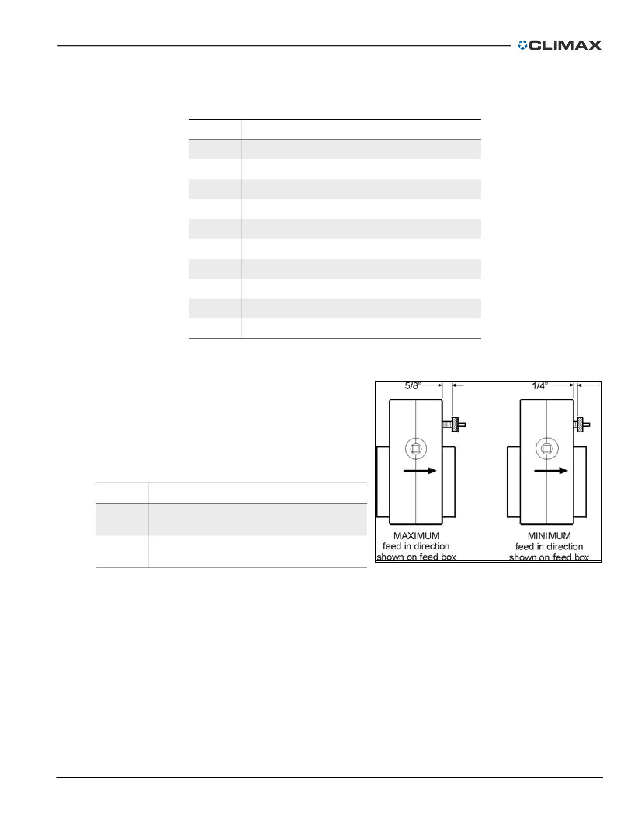
TABLE 3-6. AFU COMPONENT IDENTIFICATION
Number
Component
1
Arrow #1
2
Push to feed in direction of arrow #1
3
Feed shaft
4
Feed stop pin
5
Feed adjusting knob for direction #1
6
Auto-stop arm assembly
7
Pin
8
Push to feed in direction of arrow #2
9
Drive bushing
10
Arrow #2
3.4.2
Setting the feed rate
The feed rate is adjusted by an
adjusting screw. Each feed rate is
independent of the other; FORWARD
and REVERSE have separate feed
adjusting knobs.
TABLE 3-7. FEED BOX ARROW IDENTIFICATION
Number
Component
Maximum (feeds in the direction shown on
1
the feed box)
1
2
Minimum (feeds in the direction shown on
2
the feed box)
FIGURE 3-13. FEED BOX ARROWS
The feed rate operates by the fol-
lowing rules:
• Turning the knob counter-clockwise (out) increases the feed rate.
• Turning the knob clockwise (in) decreases the feed rate.
• The feed range is up to 0.018" (0.45 mm) per revolution of the bar.
• Maximum feed is reached when the knob is approximately 0.625" (16
mm) away from the feed box.
• Minimum feed is reached when the knob completely collapses the
compression spring approximately 0.25" (6 mm).
P/N 92974, Rev. 3
Page 41
CAUTION
The AFU will not stop until the pin is pushed in completely. To prevent
overfeeding, check that the stop arm is positioned correctly.
3.4.3
Automatic feed stop
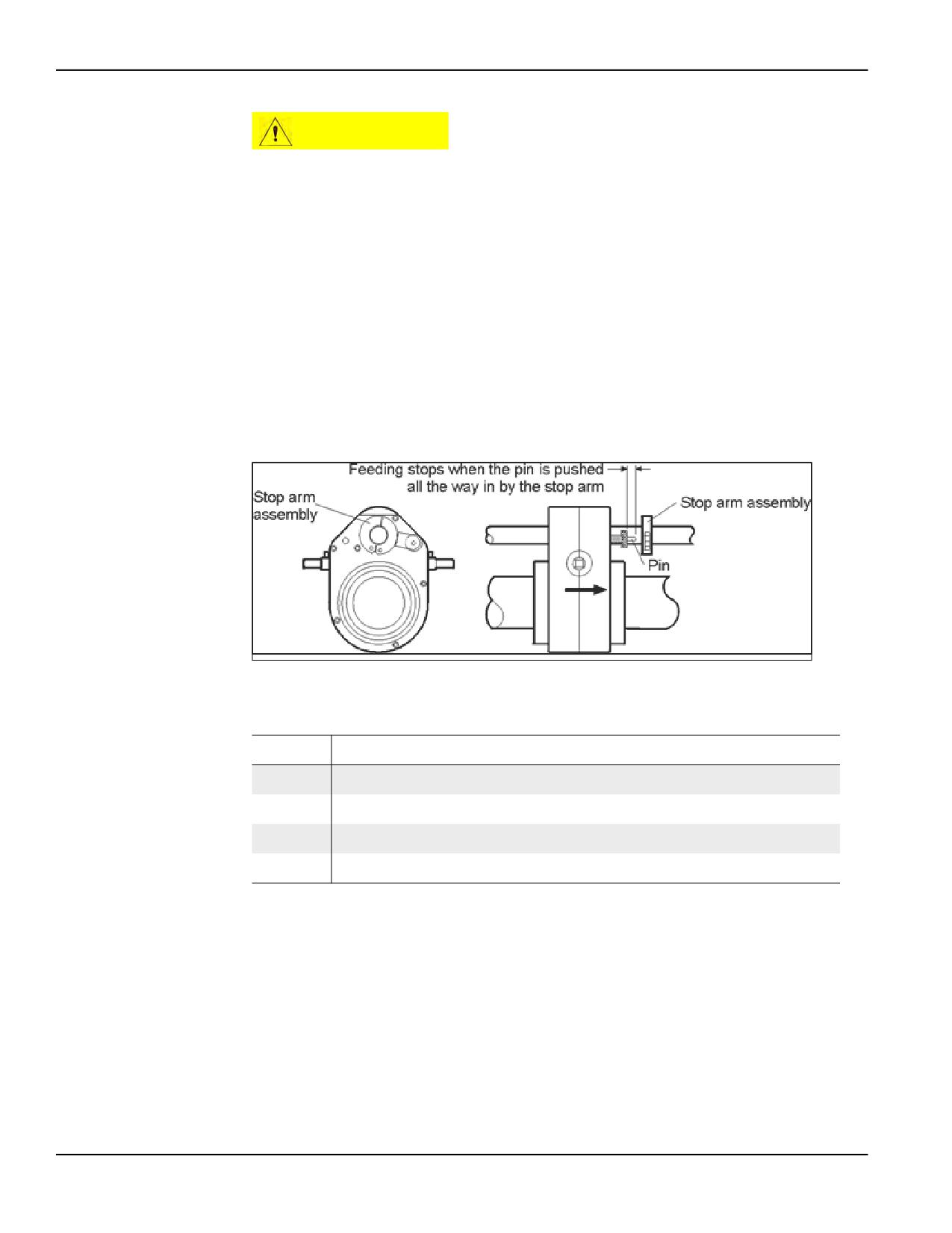
The automatic feed stop feature (see Figure 3-14) stops the AFU at any point along
the leadscrew.
Do the following to use the automatic feed stop:
1. Clamp a stop arm onto the leadscrew at the position intended for the axial
feed to stop. (Assemblies are included for stopping in either direction.)
2. Check that the stop arm is positioned to press against the feed stop screw
assembly.
2
3
1
4
FIGURE 3-14. AUTOMATIC FEED STOP
TABLE 3-8. AUTOMATIC FEED STOP IDENTIFICATION
Number
Component
1
Stop arm assembly
2
Feeding stops when the pin is pushed all the way in by the stop arm
3
Stop arm assembly
4
Pin
When the axial feed box nears the stop arm, the stop arm will depress the feed stop
screw assembly to stop the axial feed.
Do the following to retract the tool head:
1. Place the feed box in NEUTRAL.
2. Hand crank the tool bit away from the workpiece.
Page 42
BB4500-BB5000 Operating Manual
NOTICE
To protect tool bits from chipping, place the feed box in NEUTRAL before
stopping bar rotation.
3.5
POWER CONNECTION
3.5.1
Hydraulic machines
For the BB4500-BB5000, do the following to connect the hydraulic power:
1. Disconnect the mains power to the HPU.
2. Inspect all electrical cables and check the oil level in the hydraulic reser-
voir.
3. Inside the electrical enclosure, check that all three phases of mains power
(L1, L2, L3), and the safety ground wire are properly connected.
DANGER
High voltage in the electrical enclosure can cause serious or fatal injury.
Unplug the power unit before servicing the pump motor.
4. Close the electrical enclosure. Connect the power unit to mains power.
5. After checking that all hydraulic hose quick coupler fittings are clean, con-
nect the hydraulic hoses between the HPU and the hydraulic motor on the
boring bar. The hose connection may be switched to reverse the bar rota-
tion direction.
Checking the hydraulic pump rotation direction
NOTICE
Rotating the hydraulic pump in the wrong direction may damage the
pump and result in poor performance.
To check the hydraulic pump rotation direction, jog the power unit momentarily.
Check that the hydraulic pump is rotating in the direction indicated by the arrow
on the pump housing.
If it is not rotating in the direction of the arrow, do the following:
1. Turn off and lock out the electric power to the HPU.
2. Call a qualified person to open the electrical enclosure and identify wires
L1, L2, and L3 on the magnetic contactor. Switch any two of these wires.
Close the electrical enclosure.
P/N 92974, Rev. 3
Page 43
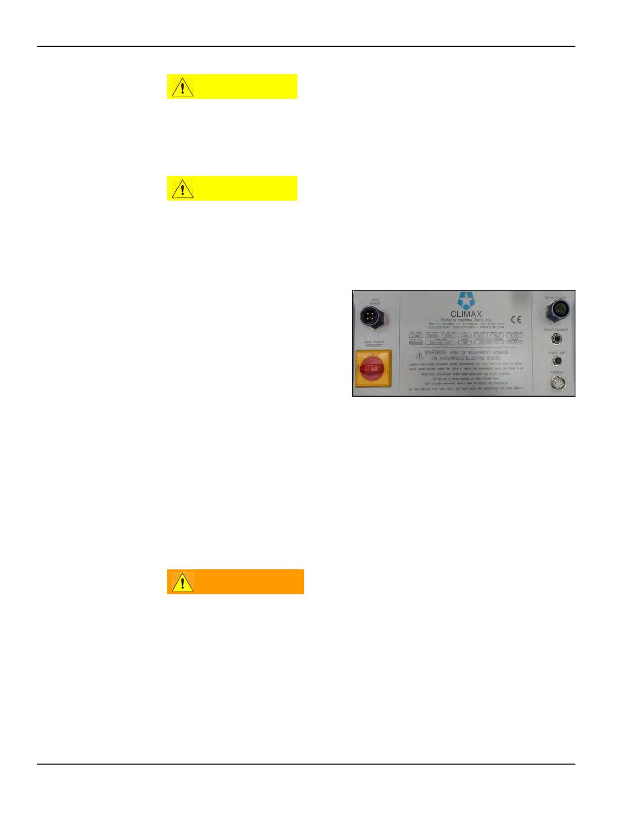
CAUTION
Do not reset the pressure relief valve on the HPU pump. It is factory set
to the correct pressure to avoid system damage.
3.5.2
BB5000 servo drive machine
CAUTION
Never disconnect any cable from this machine without first turning the
main disconnect off. Interrupting the connection between the servo
amplifier and the servo motor while energized will damage the servo
amplifier, even if the motor is stopped. Failure to comply with this
warning will void the warranty on the control system.
For the BB5000 servo drive
machines, do the following to con-
nect the servo drive power:
1. Before connecting the servo
drive system to mains
power, examine all cables
for damage. Repair or
replace the cable if neces-
FIGURE 3-15. SERVO MOTOR MAIN CONTROL PANEL
sary.
2. Connect the servo motor
encoder cable, power cable, and cooling fan power cable.
3. Connect the encoder and operator pendant cable to the main control panel
(see Figure 3-15 and Figure C-19 on page 140).
4. Plug the mains power cable into the mains power source.
The MAINS POWER DISCONNECT switch on the control panel is an external emer-
gency stop circuit that ensures operation can be stopped and power switched off
immediately.
WARNING
Electrical equipment can shock or cause an explosion if used near wet
or flammable materials. Do not operate the motor if it is wet or in a
hazardous environment.
Servo motor pendant
Table 3-9 on page 45 shows the functions of the pendant controls (seen in Figure
3-16 on page 45) used to operate a servo-motor powered machine.
Page 44
BB4500-BB5000 Operating Manual
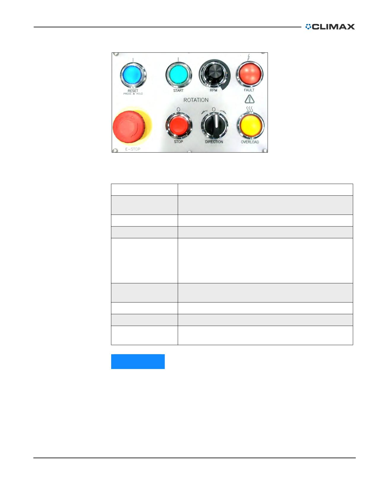
FIGURE 3-16. SERVO MOTOR PENDANT CONTROLS
TABLE 3-9. SERVO MOTOR CONTROL FUNCTIONS
Function
Action
Press and hold for three seconds to start the control system
Reset
on power up, or to reset after an E-Stop.
Start
Hold for three seconds to start the spindle rotation.
RPM
Controls the rotational bar speed from 3-230 RPM.
Indicates that the servo drive has stopped due to a fault con-
dition, such as the following:
Fault light
•
Motor overload
•
Loss of feedback
•
Motor is disconnected
Press to immediately stop all machine functions and discon-
E-stop
nect the motor from power.
Stop
Press to stop the spindle rotation.
Direction
Turn to change the direction of bar rotation.
Warns that a fault condition is imminent unless the load is
Overload indicator
reduced.
NOTICE
The 230V and 460V units cannot be converted between voltages.
There is no servo drive for the BB4500.
P/N 92974, Rev. 3
Page 45
3.5.3
Electrical machines
WARNING
Electrical equipment can shock or cause an explosion if used near wet
or flammable materials. Do not operate the motor if it is wet or exposed
to combustible materials.
CAUTION
The motor rotation reverse switch must be operated only when the
motor is completely stopped. Failure to do so can damage the
equipment.
Do the following to connect the electrical power:
1. Check the power cords and plugs for damage. Repair or replace any if nec-
essary.
2. Plug the motor into the control box.
3. Connect the control box mains power cord to a grounded outlet of the cor-
rect voltage. 120V motors are rated at 20 amps full load; 230V motors are
rated at 11.5 amps full load.
3.5.4
Pneumatic machines
For your safety and protection, the
BB4500-BB5000 pneumatic sys-
tem has an air control valve with a
brightly colored oval handle (seen
in Figure 3-17) clearly indicating
the airflow direction.
Quick-disconnects between the
incoming air supply and the
machine enable the operator to
FIGURE 3-17. AIR CONTROL VALVE HANDLE
quickly disconnect the machine if
necessary.
The pneumatic conditioning unit (PCU) air filter and lubricator must be used to
protect the pneumatic system and maintain the machine warranty. The lubricator is
set to deliver oil at a rate of 20-30 drops per minute at full throttle.
CAUTION
If the machine stops moving unexpectedly, lock out the pneumatic
safety valve located at the filter lubricator assembly before performing
any troubleshooting.
Page 46
BB4500-BB5000 Operating Manual
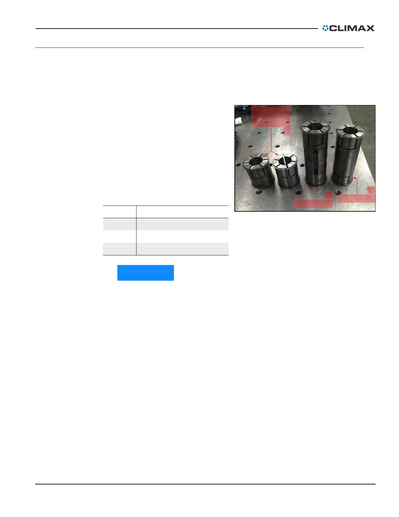
3.6
BB4500-BB5000 WITH SMALL DIAMETER BARS
For the BB4500, boring bars with a diameter of less than 1.75" (44 mm) are easily
adapted to accept the standard RDU, AFU, and the spherical bearing mounting
brackets (see Figure 3-18).
For the BB5000, boring bars with a
SPHERICAL
diameter of less than 2.25" (57.15
BEARING
COLLETS
mm) are easily adapted to accept
1
the standard RDU, AFU, and the
spherical bearing mounting brack-
ets (see Figure 3-18). This adapta-
tion for the 1.25" (32 mm) boring
bar is offered as a CLIMAX small
bore kit (P/N 28698).
3
2
TABLE 3-10. COLLET IDENTIFICATION
AFU COLLET
RDU COLLET
Number
Component
FIGURE 3-18. COLLETS (BB5000 VERSION SHOWN)
1
Spherical bearing collets
2
RDU collet
3
AFU collet
NOTICE
The small bore kit adapter collets fit into the existing collets. Do not
remove existing collets from the RDU and AFU.
The AFU collet is serrated on both ends and has no keyway. The RDU collet is ser-
rated on one end only.
The RDU collet has a keyway milled into the outside diameter with two bolt heads
visible (see Figure 3-19 on page 48). Those bolts are for retaining the key in the
inner diameter of the collet, which will accept the keyway of the 1.25" boring bar.
P/N 92974, Rev. 3
Page 47
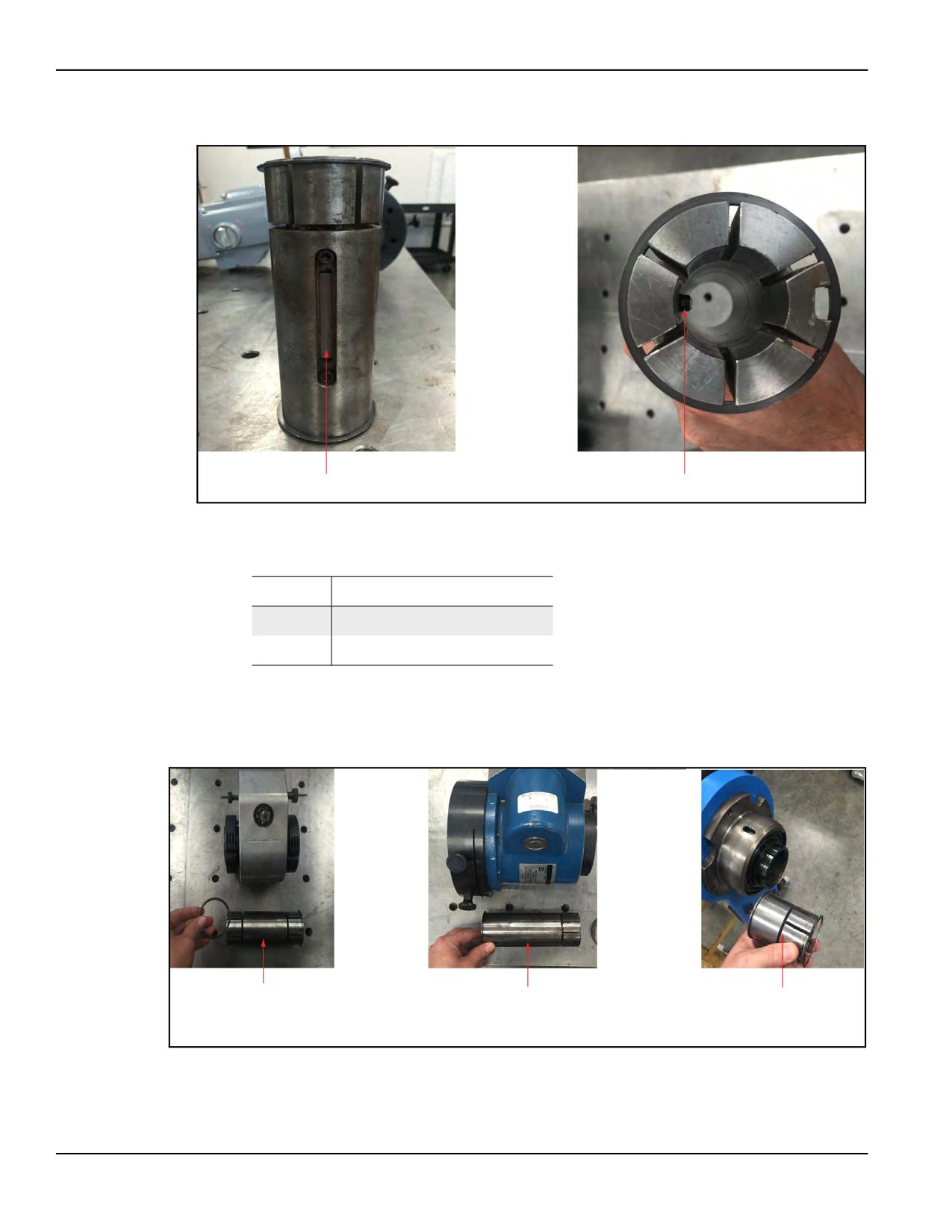
1
2
KEYWAY
KEY
FIGURE 3-19. BB5000 RDU COLLET KEYWAY
TABLE 3-11. RDU COLLET KEYWAY IDENTIFICATION
Number
Component
1
Keyway
2
Key
Do the following to install the small-bore kit, or for installing collets for the RDU,
AFU, or spherical bearings:
1. Remove a snap ring from one end of the small bore kit collet.
1
2
3
AFU SNAP
RDU SNAP
SPHERICAL
RING
RING
BEARING
SNAP RING
FIGURE 3-20. SNAP RING REMOVAL
Page 48
BB4500-BB5000 Operating Manual
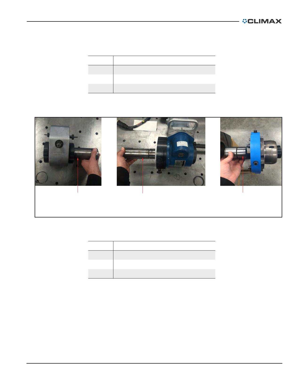
TABLE 3-12. SNAP RING REMOVAL IDENTIFICATION
Number
Component
1
AFU snap ring
2
RDU snap ring
3
Spherical bearing snap ring
2. Insert the small bore kit adapter 1.25" (32 mm) ID collet into the existing
2.25" (57 mm) ID collet.
1
2
3
AFU SMALL
SPHERICAL
RDU SMALL
BORE KIT
BEARING
BORE KIT
ADAPTER
SMALL BORE
ADAPTER
KIT ADAPTER
FIGURE 3-21. SMALL BORE KIT ADAPTER INSERTION
TABLE 3-13. SMALL BORE KIT ADAPTER IDENTIFICATION
Number
Component
1
AFU small bore kit adapter
2
RDU small bore kit adapter
3
Spherical bearing small bore kit adapter
TIP:
When installing the RDU collet, make sure to line up the keyway to
accept the key in the RDU.
3. Replace the snap ring and install the 1-1/4" bar (see Figure 3-22 on page
50).
P/N 92974, Rev. 3
Page 49
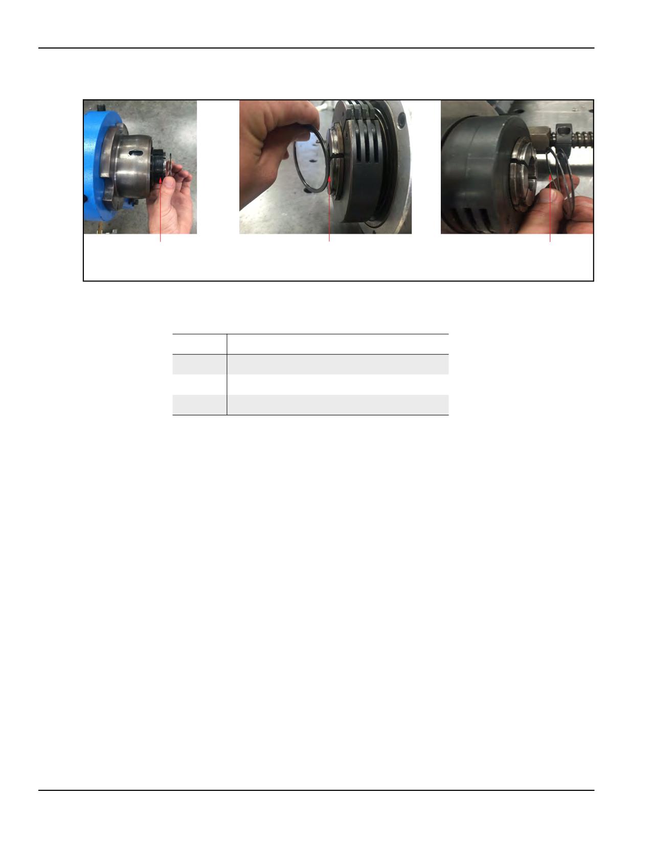
1
2
3
AFU SNAP
RDU SNAP
SPHERICAL
RING
RING
BEARING
SNAP RING
FIGURE 3-22. SNAP RING REPLACEMENT
TABLE 3-14. SNAP RING REPLACEMENT IDENTIFICATION
Number
Component
1
AFU snap ring
2
RDU snap ring
3
Spherical bearing snap ring
Page 50
BB4500-BB5000 Operating Manual
4
OPERATION
IN THIS CHAPTER:
4.1 PRE-OPERATION CHECKS - - - - - - - - - - - - - - - - - - - - - - - - - - - - - - - - - - - - - -
-51
4.2 TOOL BIT SELECTION - - - - - - - - - - - - - - - - - - - - - - - - - - - - - - - - - - - - - - - -
-52
4.3 OPERATION - - - - - - - - - - - - - - - - - - - - - - - - - - - - - - - - - - - - - - - - - - - -
-52
4.3.1 STARTING THE MACHINE - - - - - - - - - - - - - - - - - - - - - - - - - - - - - - - - - - -
-52
4.3.1.1 HYDRAULIC DRIVE - - - - - - - - - - - - - - - - - - - - - - - - - - - - - - - - - - -
-52
4.3.1.2 ELECTRICAL DRIVE
- - - - - - - - - - - - - - - - - - - - - - - - - - - - - - - - - -
-52
4.3.1.3 PNEUMATIC DRIVE - - - - - - - - - - - - - - - - - - - - - - - - - - - - - - - - - - -
-53
4.3.1.4 SERVO DRIVE (BB5000 ONLY) - - - - - - - - - - - - - - - - - - - - - - - - - - - - -
-54
4.4 SHUTDOWN - - - - - - - - - - - - - - - - - - - - - - - - - - - - - - - - - - - - - - - - - - - -
-54
4.5 DISASSEMBLY - - - - - - - - - - - - - - - - - - - - - - - - - - - - - - - - - - - - - - - - - - -
-55
Do not operate this machine without adequate training to fully understand the safe
setup, operation, and maintenance procedures.
CAUTION
To avoid serious injury, keep clear of moving machinery during
operation. Apply cutting oil with a squirt can.
For machines with air motors, if the machine stops moving
unexpectedly, lock out the pneumatic safety valve located at the filter
lubricator assembly before performing any troubleshooting.
4.1
PRE-OPERATION CHECKS
Do the following checks before operating the machine:
1. Complete the risk assessment checklist in Table 1-3 on page 5.
2. Check that the work area is clear of non-essential personnel and equipment.
3. Check that all hand tools are removed from inside the machine and the
work area.
4. Check that the machine control/observation area will not be in the path of
hot flying chips during machine operation.
5. Check the machine is securely mounted to the workpiece.
6. Check that air hoses are routed and secured to avoid tripping, entangle-
ment, damage from hot chips, or other damage should an air hose or con-
nection fail.
7. Check the tool condition and sharpness.
8. Check that power lines and cables are properly connected.
9. Check that all machine parts, including the tool head, tool bit, and collar
clamps are secure.
P/N 92974, Rev. 3
Page 51
10. Check that the feed direction and rate are correctly set.
11. Check that all preventive maintenance has been completed.
4.2
TOOL BIT SELECTION
Bar rotation speed is adjustable depending on the power option chosen (electric,
hydraulic, pneumatic). The cutting speed is primarily determined by the hardness
of the metal being machined and the type of tool bit used. Other factors include the
power source, feed and depth of cut, and cooling medium being used.
Generally, carbide cutting tools operate at a higher RPM than high-speed steel
(HSS) tools.
If using a HSS tool bit, set the speed shift lever to LOW. Chips should be the color
of the base material or no darker than a light straw in color.
When using carbide tool bits, set the speed shift lever to HIGH. These chips should
be dark brown to blue.
4.3
OPERATION
4.3.1
Starting the machine
Check that the tool bit is installed so that, as the boring bar rotates, it presents its
cutting edge to the workpiece. Before machining, lubricate the bore and tool bit
with cutting oil.
4.3.1.1
Hydraulic drive
Do the following to start the hydraulic drive:
1. Turn the HPU to its minimum flow rate (lowest speed).
2. Jog the HPU to verify direction of bar rotation. Do the following to reverse
bar rotation:
a) Turn off the HPU.
b) Reverse the hydraulic hoses.
3. With power switched on, adjust the bar speed by turning the hydraulic
speed control knob (located on the control pendant) for one of the follow-
ing results:
• Counter-clockwise to decrease RPM.
• Clockwise to increase RPM.
4.3.1.2
Electrical drive
Do the following to start the electrical drive:
1. Set the rotation speed on the speed control to minimum.
Page 52
BB4500-BB5000 Operating Manual
2. Turn on power at the motor controller.
3. Adjust the bar rotation speed as required by the bore size, tooling, and
material requirements.
4. Adjust the feed rate.
The motor has thermal and current overload protections built in. If the motor is
pushed beyond its protected range, it will stop. To prevent this, monitor the amp
meter on the controller and do not let the reading exceed its rated maximum
amperage (10.5 amps for the 230V and 20 amps for the 120V).
This motor is also reversible, allowing it to change the bar rotation direction.
CAUTION
Always stop the motor completely before switching the rotation
direction. Failure to do so may damage both the motor and the
controller.
CAUTION
Brush wear depends on the load and RPM. Regularly check both
brushes for excessive wear and replace if necessary.
4.3.1.3
Pneumatic drive
Do the following to start the pneumatic drive:
1. Using the quick disconnect fittings, connect the pneumatic motor to the
pneumatic conditioning unit (PCU).
2. Check that the incoming air pressure is 90-psi (6.2-bar) minimum.
3. Control the boring bar speed by slowly adjusting the air control valve.
NOTICE
The 3 hp (2.24 KW) air motor is reversible. Connect the airline so that,
as the boring bar rotates, the tool bit presents its cutting edge to the
workpiece. If the tool bit is backward, reverse the quick disconnects at
the motor to change the bar rotation direction.
CAUTION
If the machine stops moving unexpectedly, lock out the pneumatic
safety valve located at the filter lubricator assembly before performing
any troubleshooting.
P/N 92974, Rev. 3
Page 53
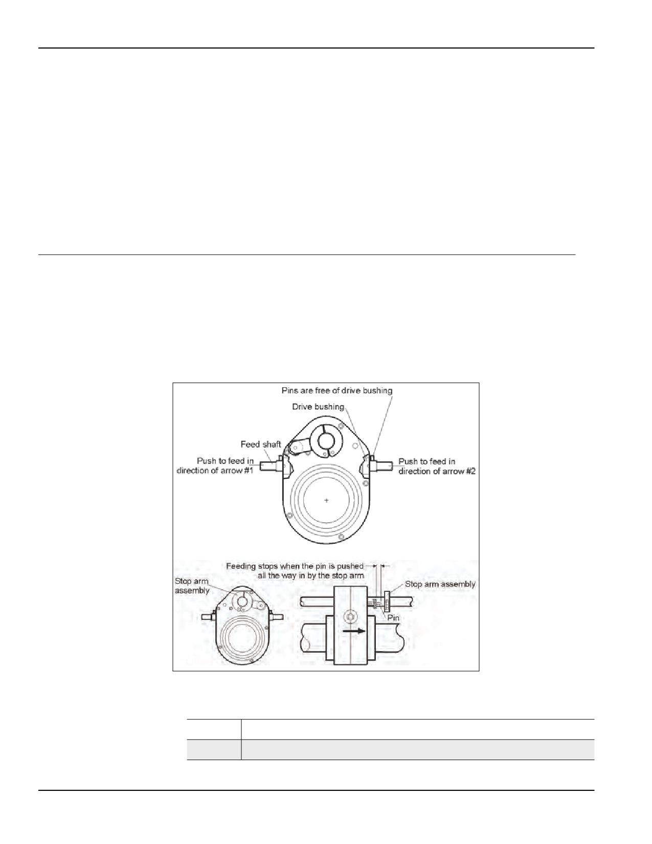
4.3.1.4
Servo drive (BB5000 only)
If using the servo drive with the BB5000, do the following to start the servo drive
(see Figure 3-16 on page 45):
1. Pull the E-stop up.
2. Press and hold the RESET button for three seconds, or until the fault light
turns off.
3. Select the rotation direction.
4. Press START.
To stop, press the STOP button.
4.4
SHUTDOWN
To protect tool bits from chipping, always place the feed box in neutral before
stopping the bar rotation.
Do the following to shut down the machine:
1. Disengage the axial feed by pushing the feed shaft until the pins on both
sides of the feed box are free of the drive bushings.
4
3
2
1
5
7
6
6
8
FIGURE 4-1. DISENGAGING THE AXIAL FEED
TABLE 4-1. AXIAL FEED DISENGAGEMENT IDENTIFICATION
Number
Component
1
Push to feed in direction of arrow #1
Page 54
BB4500-BB5000 Operating Manual
TABLE 4-1. AXIAL FEED DISENGAGEMENT IDENTIFICATION
Number
Component
2
Feed shaft
3
Drive bushing
4
Pins are free of drive bushing
5
Push to feed in direction of arrow #2
6
Stop arm assembly
7
Feeding stops when the pin is pushed all the way in by the stop arm
8
Pin
2. Turn off and disconnect power to the machine.
3. After the machine is at a complete standstill, use a brush to remove chips.
CAUTION
Even with power off, do not use your hands, compressed air, or metal
tools to remove chips. Use a brush.
4. Retract the tool from the workpiece.
4.5
DISASSEMBLY
Do the following to disassemble the BB4500-BB5000:
1. Turn off and disconnect power to the unit.
2. Remove the tool head.
3. Disconnect the leadscrew from the rotational drive unit (RDU).
P/N 92974, Rev. 3
Page 55
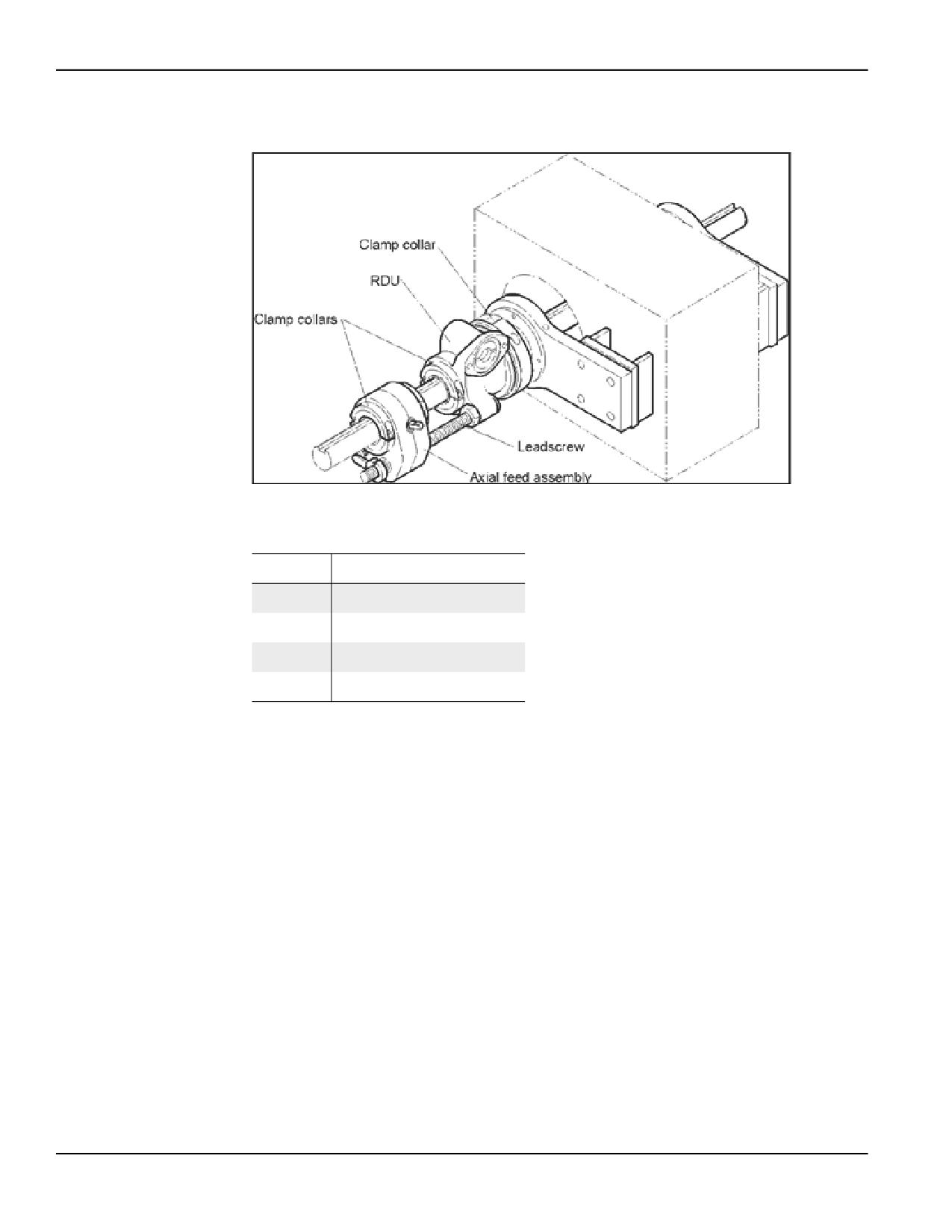
4. Loosen the clamp collars holding the axial feed unit (AFU) to the bar (see
Figure 4-2 on page 56).
1
2
1
3
4
FIGURE 4-2. AFU DISASSEMBLY COMPONENTS
TABLE 4-2. AFU DISASSEMBLY IDENTIFICATION
Number
Component
1
Clamp collars
2
RDU
3
Leadscrew
4
AFU
5. Slide the AFU off the bar.
6. Loosen the clamp ring holding the RDU to the spherical bearing.
7. Loosen the clamp collar holding the RDU to the boring bar.
8. Remove the RDU.
9. Slide the boring bar from the workpiece.
10. Remove all mounting accessories.
Page 56
BB4500-BB5000 Operating Manual
5
MAINTENANCE
IN THIS CHAPTER:
5.1 MAINTENANCE CHECKLIST
- - - - - - - - - - - - - - - - - - - - - - - - - - - - - - - - - - - - -
-57
5.2 APPROVED LUBRICANTS
- - - - - - - - - - - - - - - - - - - - - - - - - - - - - - - - - - - - - -
-58
5.3 MAINTENANCE TASKS - - - - - - - - - - - - - - - - - - - - - - - - - - - - - - - - - - - - - - - -
-59
5.3.1 AFU - - - - - - - - - - - - - - - - - - - - - - - - - - - - - - - - - - - - - - - - - - - -
-59
5.3.2 BORING BAR - - - - - - - - - - - - - - - - - - - - - - - - - - - - - - - - - - - - - - - - -
-59
5.3.3 HYDRAULIC POWER SYSTEM
- - - - - - - - - - - - - - - - - - - - - - - - - - - - - - - - -
-59
5.3.4 ELECTRIC MOTOR ASSEMBLY - - - - - - - - - - - - - - - - - - - - - - - - - - - - - - - - -
-60
5.3.5 AIR MOTOR ASSEMBLY - - - - - - - - - - - - - - - - - - - - - - - - - - - - - - - - - - - -
-60
5.3.6 BB5000 SERVO MOTOR
- - - - - - - - - - - - - - - - - - - - - - - - - - - - - - - - - - -
-61
5.3.7 4:1 RDU GEARBOX
- - - - - - - - - - - - - - - - - - - - - - - - - - - - - - - - - - - - -
-61
5.3.8 CUTTING FLUID
- - - - - - - - - - - - - - - - - - - - - - - - - - - - - - - - - - - - - - -
-61
5.4 QUALITY CHECKS
- - - - - - - - - - - - - - - - - - - - - - - - - - - - - - - - - - - - - - - - -
-61
5.5 TROUBLESHOOTING
- - - - - - - - - - - - - - - - - - - - - - - - - - - - - - - - - - - - - - - -
-62
5.1
MAINTENANCE CHECKLIST
Table 5-1 lists maintenance intervals and tasks.
TABLE 5-1. MAINTENANCE INTERVALS AND TASKS
Interval
Task
Reference
Inspect the power cord for damage and replace as necessary.
--
Fill the lubricator oil cup in the air motor assembly with 6 oz (177.4
Section 5.3.5 on
mL) of AW 32.
page 60
Spray the ACME screw and tool heads with WD-40.
Before each use
Section 5.3.2 on
Clean and lightly oil the bar.
page 59
Spray the spherical bearing mounting bracket bearing mounts with
--
WD-40.
Before and after
Remove debris, oil, and moisture from machine surfaces.
--
each use
P/N 92974, Rev. 3
Page 57
TABLE 5-1. MAINTENANCE INTERVALS AND TASKS (CONTINUED)
Interval
Task
Reference
Clean and lightly oil (do not grease) the leadscrew in the axial feed
Section 5.3.1 on
unit (AFU).
page 59
Every six months, fill the 4:1 servo rotational drive unit (RDU) gear-
Section 5.3.7 on
box with 1 oz (29.5 mL) of Mobil SHC 634 synthetic oil.
page 61
Every six months, repack the spherical bearings in the spherical
--
bearing mounting bracket with 2 cc’s (2 mL) of Jetlube 550.
Every six months or 500 hours, repack the gearbox with one
Periodically
--
ounce of Mobilith SHC 460 Synthetic gear grease.
Every two years, replace the hydraulic oil with AW 32. Fill to the
Section 5.3.3 on
sight glass.
page 59
Section 5.3.4 on
Check both brushes for excessive wear and replace if necessary.
page 60
Check the air system periodically to verify that the air pressure is
Section 5.3.5 on
90 psi (6.2 bar).
page 60
Section 5.3.1 on
Disassemble the AFU to clean, lubricate, and replace the seals.
page 59
Annually
Repack the AFU gearbox with 1 oz (29.6 mL) of Mobilith SHC 460
Section 5.3.1 on
grease.
page 59
As needed
Sharpen or replace the tool bits.
--
5.2
APPROVED LUBRICANTS
CLIMAX recommends using the following lubricants at the locations indicated.
CAUTION
Avoid damage, premature machine wear, and protect your warranty by
using only approved lubricants.
TABLE 5-2. APPROVED LUBRICANTS
Application Area
Lubricant
Quantity
Frequency
4:1 RDU
Mobilith SHC 460 Synthetic
1 oz
Every 6 months
12:1 RDU (BB5000
Mobil SHC 634 Synthetic
5 oz
Every 6 months
only)
AFU
Mobilith SHC 460
1 oz
Yearly
Spherical bearings
JetLube 550
2 cc
Every 6 months
To sight
Hydraulic oil
AW 32
Every 2 years
glass
Page 58
BB4500-BB5000 Operating Manual
TABLE 5-2. APPROVED LUBRICANTS (CONTINUED)
Application Area
Lubricant
Quantity
Frequency
Per use through
Air motor
AW 32
6 oz
the lubricator
ACME screw
Boring bar
As
WD 40
Per use by hand
required
Tool heads
Unpainted surfaces
As
Cutting fluid
DoAll AL2000
As required
required
Long-term rust pre-
As
For storage more
LPS-3
ventative
required
than 3 months
As
Tool bits, work piece
Koolkut
Per use by hand
required
5.3
MAINTENANCE TASKS
Maintenance tasks are described in the following sections.
5.3.1
AFU
Clutch performance may be compromised if the machine has been “crashed,” has
seen over a thousand hours of operation, or is operated in a dirty environment.
If the axial feed fails, check that the shear pins are intact. Extra pins are included
with the assembly. The pins must be in place (notched end out) to engage the feed.
NOTICE
Freezing temperatures may cause the axial feed box to run sluggishly.
5.3.2
Boring bar
Check the bar regularly for nicks, cuts, or abrasions. Dress the bar smooth if neces-
sary. A bar with nicks or gouges can damage the bearing supports and RDU
beyond repair. Wipe the bar clean with solvent to remove dirt and chips.
5.3.3
Hydraulic power system
For information on maintaining the hydraulic power system, see the manufac-
turer’s documentation for your hydraulic system.
P/N 92974, Rev. 3
Page 59
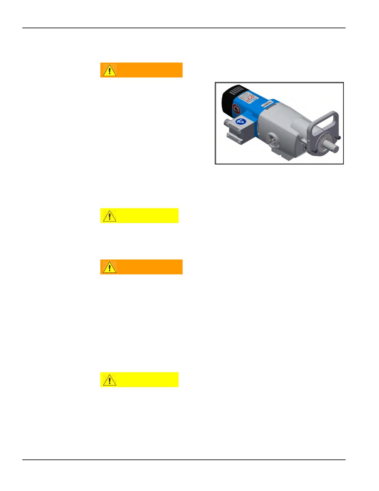
5.3.4
Electric motor assembly
WARNING
The handle (PN 75648)
clamped onto the motor acts
as a torque restraint and only
an authorized CLIMAX
representative should remove
and reinstall it. If the handle
needs to be removed, contact
CLIMAX. Failure to do this
could cause severe damage
to the machine or bodily injury.
FIGURE 5-1. ELECTRIC MOTOR WITH HANDLE
Replace or repair any damaged or
abraded parts, including brushes.
Use only grounded, properly rated electrical outlets.
CAUTION
Brush wear mostly depends on the load and RPM. Depending on
operating conditions, periodically check both brush for excessive wear
and replace if necessary.
WARNING
Electrical equipment can shock or cause an explosion if used near wet
or flammable materials. Do not operate the motor if it is wet or exposed
to combustible materials.
5.3.5
Air motor assembly
Do the following to increase the life of the air motor:
• Route the air supply through a lubricator and filter.
• Use nonrestrictive air lines and fittings.
• Set the air motor speed only by adjusting the air control valve.
CAUTION
Do not attempt to adjust air motor speed by changing the in-line air
pressure from 90 psi (6.2 bar).
• Use air oil that has antioxidants and rust inhibitors. The lubricator
should deliver oil at a rate of 20-30 drops per minute at full throttle.
• Drain water from the air filter.
Page 60
BB4500-BB5000 Operating Manual
5.3.6
BB5000 servo motor
CAUTION
Let the surface of the servo cool before handling.
Servo temperatures of less than 140° F (60° C) are expected, as well as the forma-
tion of an oil droplet over an eight-hour use period. Replace oil with 5 ounces of
Mobil SHC 634 Oil after the first 40 hours and then additionally every 80 hours.
Running at a high RDU temperature of more than 220° F (104° C) for over 30 min-
utes at a time or reaching an RDU temperature of 260° F (127° C) will limit the life
of the RDU and can create oil leakage.
Replace oil with 5 ounces of Mobil SHC 634 Oil every 40 hours.
If the motor does not stop when the speed control knob is turned to zero, see
Appendix D on page 143.
5.3.7
4:1 RDU gearbox
Improperly packed bearings or improperly torqued bearing nuts will significantly
damage the gearbox. Have the gearbox serviced at CLIMAX every six months in
order to maintain the warranty.
5.3.8
Cutting fluid
Only use water-based cutting fluids with the CLIMAX air mist system. Refill the
reservoir with DoAll AL2000 as required.
5.4
QUALITY CHECKS
TABLE 5-3. QUALITY CHECKS
Area
Check
Rotate the collet by hand, checking for free movement.
AFU
Check the feed engagement pins, feed operation, feed stop pins, and that feed
screws are not bent.
RDU
Manually retract the spring plungers and drive key, checking for free movement.
Tool heads
All hardware is present and in good condition for each tool head.
Bearing mounts
All single-arm mount screws and washers are in good condition.
Tack weld plates (P/N 19869)
Welds are ground off and a flat surface is present for welding.
Safety devices and labels
Present and in good condition (see Section 1.7 on page 6).
Steel container (P/N 37732)
In good condition and all packaging materials are new.
P/N 92974, Rev. 3
Page 61
5.5
TROUBLESHOOTING
This section is intended to help you solve basic machine performance problems.
For serious maintenance or if you have questions on the following procedures,
contact CLIMAX.
TABLE 5-4. TROUBLESHOOTING
Problem
Remedy
•
Fully engage the feed shaft pin in the bushing slot.
•
Check that the pin has not sheared.
•
Clean the leadscrew.
AFU does not
•
Check that the feed rate is not too low.
advance the bar
•
Check that the AFU is clamped tightly to the bar.
•
Check that none of the clamp collars, except those on the AFU, are over tightened.
•
Check that the stop arm has not depressed one of the stop feed screw assemblies.
•
Sharpen the tool bit.
•
Decrease the nose radius on the tool bit.
•
Increase the feed rate.
Tool chatter
•
Increase or decrease the drive motor speed.
•
Change the depth of cut.
•
Add additional support arms or place the existing support arms closer to the workpiece.
Machine is
Tighten all clamps and hardware. Provide additional support.
unstable
•
Check that the HPU is turned on.
•
Check that the HPU pump motor is rotating as indicated by the arrow on the pump body
(see Section 3.5.1 on page 43).
•
Check the oil level in the HPU.
RDU will not
•
Check that the speed control is at maximum flow.
rotate
•
Check the hydraulic hose connections.
•
On electric powered units, check electrical connections and circuit breakers (see Section
3.5.3 on page 46).
•
Check that the control box on electric motors is plugged into the motor and turned on.
Feed is in
Check the feed shaft position on the AFU (see Section 3.4 on page 40).
wrong direction
•
Check the fluid level and add more if necessary.
HPU fails to
•
Check that the pump motor is turning in the correct direction (see Section 3.5.1 on
deliver fluid
page 43).
•
Check hydraulic connections for obstructions or leaks.
•
Check that the power unit and electrical supply are compatible.
•
Check that the unit is plugged in.
HPU motor does
•
Check for faulty wiring.
not run
•
Check the reset switch in the electrical box.
•
Check the fuses in the electrical box.
Servo motor
does not stop
See Appendix D on page 143.
when turned to
zero
Page 62
BB4500-BB5000 Operating Manual
6
STORAGE AND SHIPPING
IN THIS CHAPTER:
6.1 STORAGE - - - - - - - - - - - - - - - - - - - - - - - - - - - - - - - - - - - - - - - - - - - - -
-63
6.1.1 SHORT-TERM STORAGE
- - - - - - - - - - - - - - - - - - - - - - - - - - - - - - - - - - -
-63
6.1.2 LONG-TERM STORAGE - - - - - - - - - - - - - - - - - - - - - - - - - - - - - - - - - - - -
-63
6.2 SHIPPING - - - - - - - - - - - - - - - - - - - - - - - - - - - - - - - - - - - - - - - - - - - - -
-63
6.3 DECOMMISSIONING - - - - - - - - - - - - - - - - - - - - - - - - - - - - - - - - - - - - - - - - -
-64
6.1
STORAGE
Proper storage of the boring machine will extend its usefulness and prevent undue
damage.
Before storing, do the following:
1. Clean the machine with solvent to remove grease, metal chips, and mois-
ture.
2. Remove hoses to the HPU. Do not remove the ramp feature hoses.
Store the boring machine in its original shipping container. Keep all packing mate-
rials for repackaging the machine.
6.1.1
Short-term storage
Do the following for short-term storage (three months or less):
1. Remove the tooling.
2. Lower and support the spindle.
3. Remove the hoses to the HPU. Do not remove the ramp feature hoses.
4. Clean the machine to remove dirt, grease, metal chips, and moisture.
5. Spray all black and bare metal surfaces with LPS-3 to prevent corrosion.
6. Store in a protected area.
6.1.2
Long-term storage
For long-term storage (longer than three months), follow the short-term storage
instructions, but use LPS-3 instead of LPS-2.
6.2
SHIPPING
The boring machine can be shipped in its original shipping container.
P/N 92974, Rev. 3
Page 63
6.3
DECOMMISSIONING
To decommission the boring machine before disposal, remove the drive assembly
from the RDU and dispose of the drive assembly separately from the rest of the
machine components. Refer to the BB4500 exploded views in Appendix A on
page 65 and the BB5000 exploded views in Appendix B on page 85.
Page 64
BB4500-BB5000 Operating Manual
APPENDIX A BB4500 ASSEMBLY DRAWINGS
Drawing list
FIGURE A-1. AXIAL FEED UNIT ASSEMBLY (P/N 43378)
- - - - - - - - - - - - - - - - - - - - - - - - - - - - - - 66
FIGURE A-2. AXIAL FEED UNIT ASSEMBLY PARTS LIST (P/N 43378) - - - - - - - - - - - - - - - - - - - - - - - - - 67
FIGURE A-3. BORING HEADS SET ASSEMBLY (P/N 43576) - - - - - - - - - - - - - - - - - - - - - - - - - - - - - 68
FIGURE A-4. BORING HEADS SET 4-10 METRIC DIAMETER ASSEMBLY (P/N 43576) - - - - - - - - - - - - - - - - - - 69
FIGURE A-5. BORING HEADS SET 4-10" DIAMETER ASSEMBLY (P/N 43575) - - - - - - - - - - - - - - - - - - - - - 70
FIGURE A-6. RDU 2ND GEN ASSEMBLY (P/N 53912)
- - - - - - - - - - - - - - - - - - - - - - - - - - - - - - - 71
FIGURE A-7. RDU 2ND GEN ASSEMBLY (P/N 53912)
- - - - - - - - - - - - - - - - - - - - - - - - - - - - - - - 72
FIGURE A-8. HYDRAULIC MOTOR ASSEMBLY (P/N 39848)
- - - - - - - - - - - - - - - - - - - - - - - - - - - - - 73
FIGURE A-9. SINGLE-ARM MOUNT ASSEMBLY (P/N 43262) - - - - - - - - - - - - - - - - - - - - - - - - - - - - - 74
FIGURE A-10. UNIVERSAL MOUNT ASSEMBLY (P/N 43267) - - - - - - - - - - - - - - - - - - - - - - - - - - - - - 75
FIGURE A-11. DOUBLE-ARM BEARING MOUNT ASSEMBLY (P/N 43279)
- - - - - - - - - - - - - - - - - - - - - - - 76
FIGURE A-12. LARGE AND SMALL SET CONES ASSEMBLY (P/N 49060)
- - - - - - - - - - - - - - - - - - - - - - - 77
FIGURE A-13. EIBENSTOCK MOTOR ASSEMBLY (P/N 88012) - - - - - - - - - - - - - - - - - - - - - - - - - - - - 78
FIGURE A-14. EIBENSTOCK MOTOR ASSEMBLY -- GEN. 2 ONLY - - - - - - - - - - - - - - - - - - - - - - - - - - - 79
FIGURE A-15. EIBENSTOCK MOTOR ASSEMBLY PARTS LIST -- GEN. 2 ONLY - - - - - - - - - - - - - - - - - - - - - - 80
TABLE A-1. BB4500 RECOMMENDED SPARE PARTS - - - - - - - - - - - - - - - - - - - - - - - - - - - - - - - - 81
TABLE A-2. BB4500-BB5000 SPARE PARTS KIT (P/N 97276)
- - - - - - - - - - - - - - - - - - - - - - - - - - - 81
TABLE A-3. BB4500 TOOL KIT IN INCHES (P/N 43580) - - - - - - - - - - - - - - - - - - - - - - - - - - - - - - - 82
TABLE A-4. BB4500 TOOL KIT IN METRIC (P/N 43582) - - - - - - - - - - - - - - - - - - - - - - - - - - - - - - - 83
P/N 92974, Rev. 3
Page 65
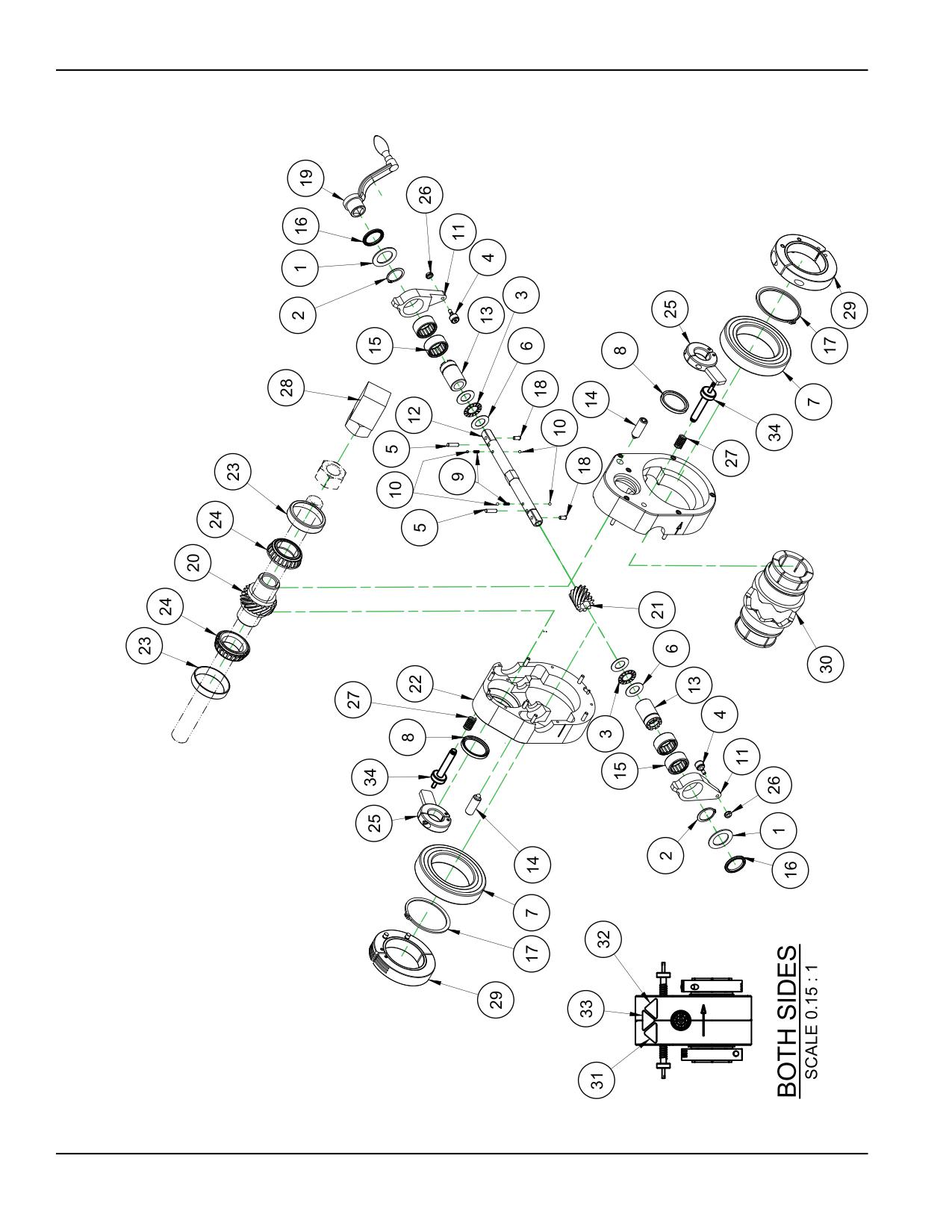
FIGURE A-1. AXIAL FEED UNIT ASSEMBLY (P/N 43378)
Page 66
BB4500-BB5000 Operating Manual
3$576 /,67
,7(0
47<
31
'(6&5,37,21
:$6+(5 7+5867
,' ;
2' ;
5,1* 61$3
2'
%5* 7+5867
,' ;
2' ;
%5* &$0 )2//2:
;
3,1 '2:(/
[
:$6+(5 7+5867
,' ;
2' ;
%5* %$//
;
;
6($/
,' ;
2' ;
.%
635,1* &203
2' ;
:,5( ;
/21* 67$,1/(66
%$// 67((/
',$
$50 5$7&+(7
6+$)7 )(('
%86+,1* '5,9(
635,1* 3/81*(5
/,*+7 )25&(
%5* 52//(5 &/87&+
;
;
6($/
,' ;
2' ;
+0
/,3
5,1* 61$3
%(9(/('
3/81*(5 %$// 386+),7
+$1'/( &5$1. 02',),('
/($' 187 %%
%%
$;,$/ )((' 90,
*($5 +(/,&$/ $;,$/ )((' %%
$66(0%/(' $;,$/ )((' 81,7 +286,1*
%5* &83
2' [
:,'(
%5* &21(
,' ;
:,'(
6723
$50
$66<
187
81) .(36
635,1* &203
2' ;
:,5( ;
%/2&. 7$&.:(/' %%
&/$03 &2//$5 02',),('
5' *(1 $)8
&2//(7 %%
/$%(/ :$51,1* +$1' &586+ )25&(
/$%(/ :$51,1* (17$1*/(0(17 2) +$1' 527$7,1* 6+$)7
/$%(/ :$51,1* &877,1* 2) ),1*(56 527$7,1* %/$'( *5$3+,&
7$// 75,$1*/( <(//2:
6&5(: $66< )((' 6723 *(1
FIGURE A-2. AXIAL FEED UNIT ASSEMBLY PARTS LIST (P/N 43378)
P/N 92974, Rev. 3
Page 67
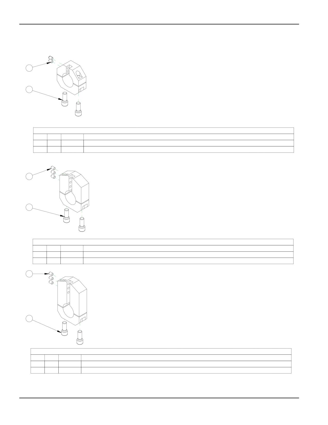
1
TOOL HEAD METRIC 4 TO 6 DIA 1-3/4 BAR BB4500
2
43563
PARTS LIST
ITEM
QTY
P/N:
DESCRIPTION
1
2
35214
SCREW M8 X 1.25 X 12mm SSSCP
2
2
40697
SCREW M12 X 1.75 X 30mm SHCS
2
TOOL HEAD METRIC 6 TO 8 DIA 1-3/4 BAR BB4500
43564
1
PARTS LIST
ITEM
QTY
P/N:
DESCRIPTION
1
2
40697
SCREW M12 X 1.75 X 30mm SHCS
2
3
43120
SCREW M8 X 1.25 X 12 SSSFP
1
TOOL HEAD METRIC 8 TO 10 DIA 1-3/4 BAR BB4500
43565
2
PARTS LIST
ITEM
QTY
P/N:
DESCRIPTION
1
3
35214
SCREW M8 X 1.25 X 12mm SSSCP
2
2
40697
SCREW M12 X 1.75 X 30mm SHCS
FIGURE A-3. BORING HEADS SET ASSEMBLY (P/N 43576)
Page 68
BB4500-BB5000 Operating Manual
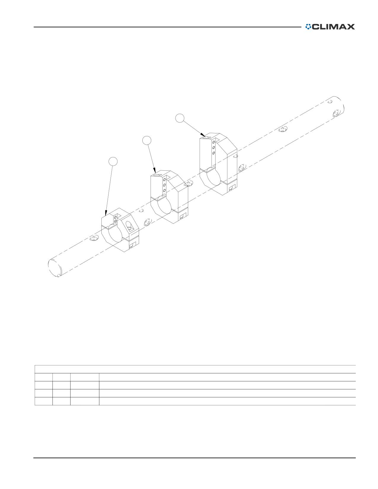
3
2
1
PARTS LIST
ITEM
QTY
P/N:
DESCRIPTION
1
1
43563
TOOL HEAD METRIC 4 TO 6 DIA 1-3/4 BAR BB4500
2
1
43564
TOOL HEAD METRIC 6 TO 8 DIA 1-3/4 BAR BB4500
3
1
43565
TOOL HEAD METRIC 8 TO 10 DIA 1-3/4 BAR BB4500
FIGURE A-4. BORING HEADS SET 4-10 METRIC DIAMETER ASSEMBLY (P/N 43576)
P/N 92974, Rev. 3
Page 69
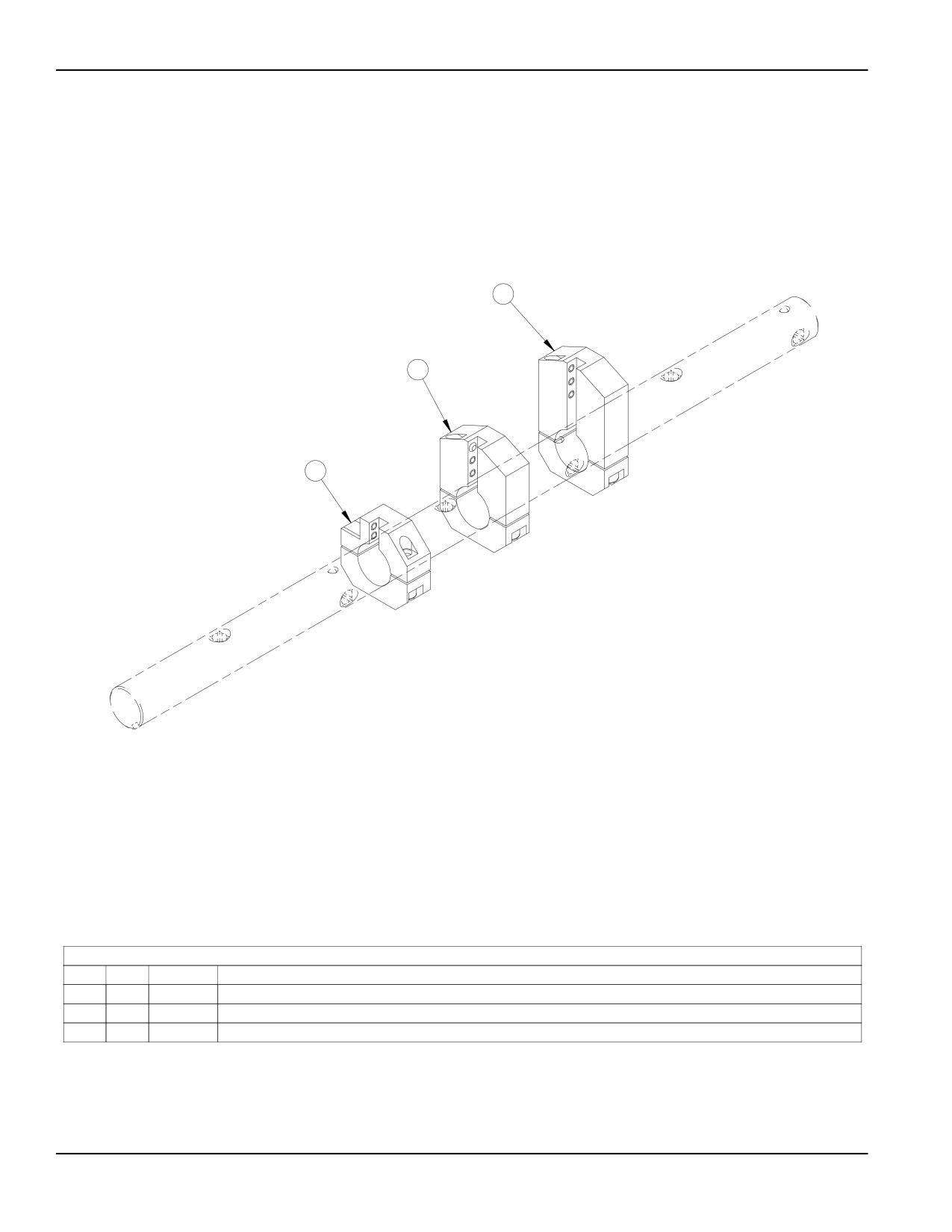
3
2
1
PARTS LIST
ITEM
QTY
P/N:
DESCRIPTION
1
1
43492
TOOL HEAD 4 TO 6 DIA 1-3/4 BAR
2
1
43493
TOOL HEAD 6 TO 8 DIA 1-3/4 BAR BB4500
3
1
43494
TOOL HEAD 8 TO 10 DIA 1-3/4 BAR
FIGURE A-5. BORING HEADS SET 4-10" DIAMETER ASSEMBLY (P/N 43575)
Page 70
BB4500-BB5000 Operating Manual
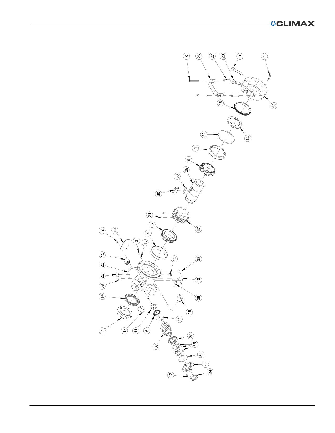
FIGURE A-6. RDU 2ND GEN ASSEMBLY (P/N 53912)
P/N 92974, Rev. 3
Page 71
PARTS LIST
ITEM
QTY
P/N:
DESCRIPTION
1
7
10160
SCREW 1/4-20 X 3/4 SHCS
2
4
10588
SCREW DRIVE #2 x 1/4 HOLE SIZE .089
3
2
11684
SCREW 5/16-18 X 3/4 SSSCP
4
2
11821
BRG CUP 4.4375 OD X .750 WIDE
5
2
11822
BRG CONE 2.75 ID X 1.00 WIDE
6
1
12387
BRG THRUST 1.259 ID X 1.937 OD X .0781
7
1
12395
CLAMP COLLAR SPLIT HINGED 2-1/2 ID
8
2
12592
SCREW 1/4-20 X 2-3/4 SHCS
9
1
15212
SCREW 1/2-20 X 2-1/4 SHCS
10
2
16594
BALL NYLON 3/16 DIA
11
2
16666
WASHER THRUST 1.250 ID X 1.937 OD X .060
12
6
19232
SCREW 10-24 X 3/8 SHCS
13
1
21956
FTG PLUG 3/8 NPTM SOCKET
14
2
27348
SEAL 2.750 ID X 4.000 OD X .375
15
1
27353
BRG NEEDLE 1 ID X 1-1/4 OD X 1 CLOSED
16
1
28219
NUT MAIN BRG PRELOAD
17
1
28220
BUSHING LEADSCREW FLANGED
18
1
28589
BUSHING FLANGED 1 5P ACME THREADED
19
1
29154
PLATE SERIAL YEAR MODEL CE 2.0 X 3.0
20
2
29207
SPRING PLUNGER HAND RETRACT 1/2 X 13
21
2
45900
SCREW 1/4-28 X 1/2 SHCS
22
1
46902
LABEL WARNING HOT SURFACE
23
1
49665
HOUSING RDU BB5000 4TH
24
1
49667
CAP WORM HOUSING BB5000 4TH GEN
25
1
52307
BRG BALL THRUST 40 MM ID X 60 MM OD X 13 MM
26
1
53610
HANDLE PULL 1/4 CBORE MTG 2.17 X 5.75 X 1.02W COATED
27
2
53613
SPACER .67 OD X .266 ID X 1.875 LG
28
1
53910
CLAMP RING RDU MOUNT BB4500 HD
29
1
53911
COLLET MAIN DRIVE BB4500 4TH GEN
30
1
53913
KEY MAIN DRIVE BB4500 HD
31
1
54920
RING O 1/16 X 2-1/4 ID X 2-3/8 OD
32
1
54921
RING O 4-3/8 ID X 4-5/8 OD X 1/8
33
1
54922
RING O 1/16 X 1-3/8 ID X 1-1/2 OD VITON 75 DUROMETER
34
1
55708
SEAL 1.500 ID X 2.000 OD X .375 HIGH TEMP
35
A/R
55784
SHIM 1.7 ID X 2.3 OD .001 THICK
35
A/R
55790
SHIM 1.7 ID X 2.3 OD .002 THICK
35
A/R
55791
SHIM 1.7 ID X 2.3 OD .005 THICK
36
1
59044
LABEL WARNING CONSULT OPERATOR'S MANUAL
37
1
73954
SET WORM GEAR 4:1 BB5000 4TH GEN 1PC WORM
38
1
78741
LABEL WARNING CRUSH FOOT
39
1
78748
LABEL WARNING FLYING DEBRIS/LOUD NOISE
40
1
80207
LABEL WARNING - ENTANGLEMENT/ROTATING SHAFT GRAPHIC 1.95 TALL TRIANGLE YELLOW
FIGURE A-7. RDU 2ND GEN ASSEMBLY (P/N 53912)
Page 72
BB4500-BB5000 Operating Manual

5
2
1
4
3
PARTS LIST
ITEM
QTY
P/N:
DESCRIPTION
1
2
11238
WASHER LOCK 1/2
2
2
11826
SCREW 1/2-13 X 1-1/4 HHCS
3
1
A/R
SEE CHART
4
1
39828
KIT FTG 1/2 HYD QUICK COUPLERS
5
1
78619
LABEL WARNING HOT SURFACE GRAPHIC 1.95" TALL TRIANGLE YELLOW (KB)
PART No
DESCRIPTION
MOTOR HYD P/N
39837
MOTOR ASSY HYD 2.2 CU IN KEYED 1/2 FTG
27477
39843
MOTOR ASSY HYD 3.6 CU IN KEYED 1/2 FTG
20684
39844
MOTOR ASSY HYD 5.7 CU IN KEYED 1/2 FTG S-SERIES
21530
39845
MOTOR ASSY HYD 7.3 CU IN KEYED 1/2 FTG
20231
39846
MOTOR ASSY HYD 8.9 CU IN KEYED S-SERIES 1/2 FTG
21531
39847
MOTOR ASSY HYD 14.1 CU IN KEYED 1/2 FTG
34585
43451
MOTOR ASSY HYD 11.3 CU IN KEYED 1/2 FTG
21532
43452
MOTOR ASSY HYD 17.9 CU IN KEYED 1/2 FTG
21534
43552
MOTOR ASSY HYD 22.5 CU IN KEYED SHAFT
30567
FIGURE A-8. HYDRAULIC MOTOR ASSEMBLY (P/N 39848)
P/N 92974, Rev. 3
Page 73
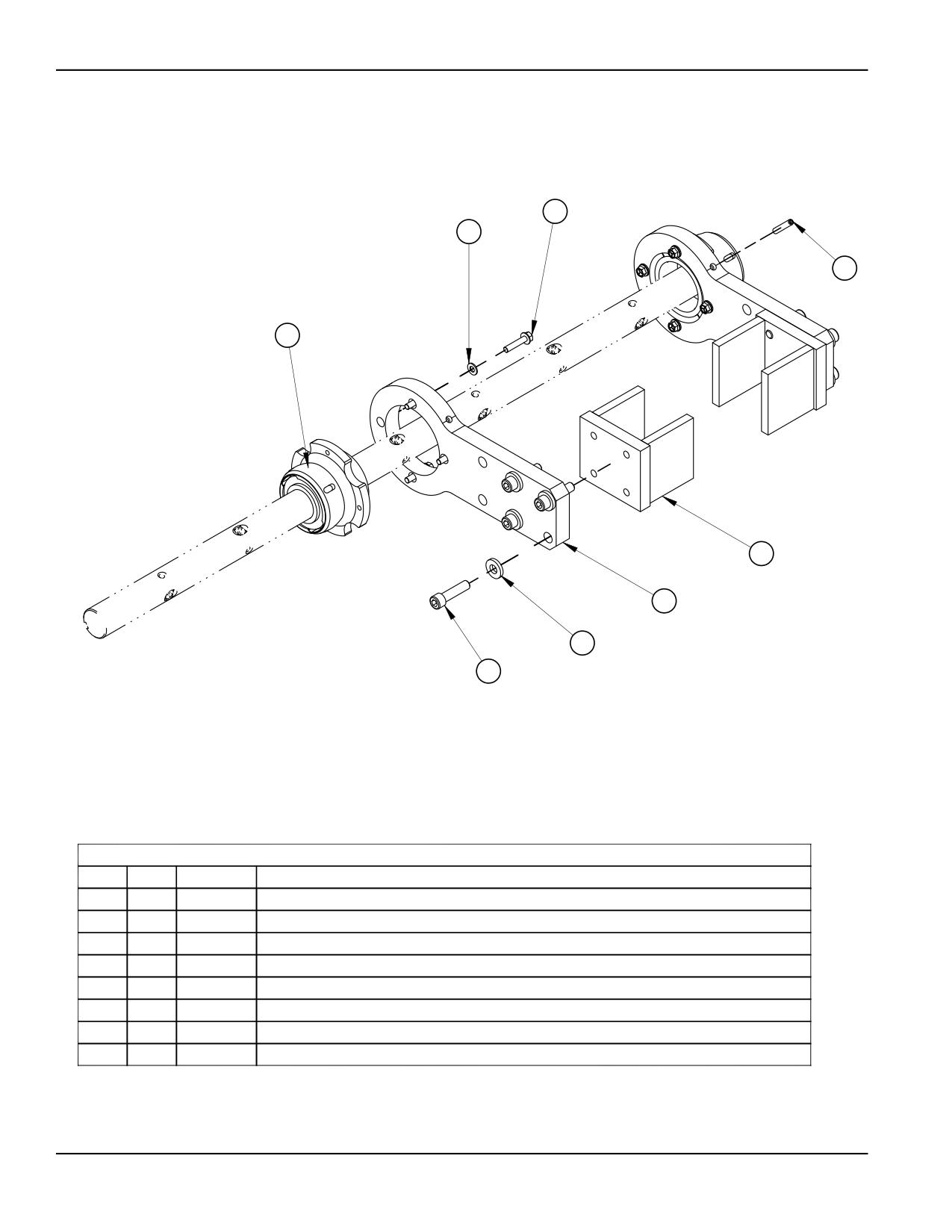
8
1
4
5
7
6
3
2
PARTS LIST
ITEM
QTY
P/N:
DESCRIPTION
1
8
13489
WASHER 5/16 FLTW SAE
2
8
14036
SCREW 1/2-13 X 2 SHCS
3
8
17145
WASHER 1/2 FLTW HARDENED 1-1/8 OD X 3/16 THK
4
8
20174
SCREW 5/16-18 X 1-3/4 SSSFP
5
2
43264
MOUNT BRG SPHERICAL ARM BB45000 STD
6
2
43265
BRACKET MOUNTING ARM
7
2
43266
PLATE BEARING SCAB
8
8
45365
SCREW 5/16-24 X 1.500 HHCS FLANGED BLK OX
FIGURE A-9. SINGLE-ARM MOUNT ASSEMBLY (P/N 43262)
Page 74
BB4500-BB5000 Operating Manual
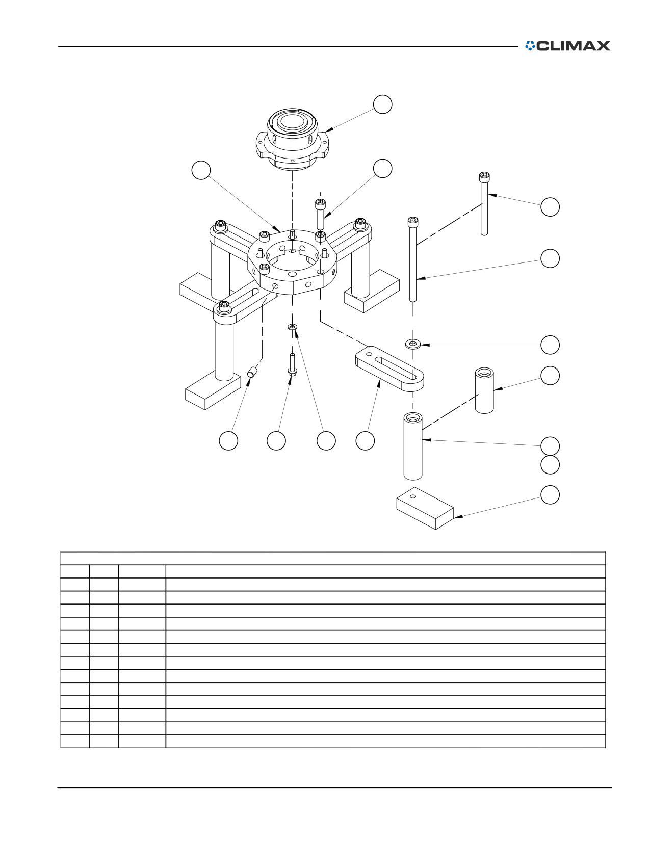
12
7
4
2
1
5
10
6
13
3
8
11
13
9
PARTS LIST
ITEM
QTY
P/N:
DESCRIPTION
1
4
11223
SCREW 1/2-13 X 7 SHCS
2
4
11879
SCREW 1/2-13 X 5 SHCS
3
4
13489
WASHER 5/16 FLTW SAE
4
4
14036
SCREW 1/2-13 X 2 SHCS
5
4
22662
WASHER 1/2 FLTW HARDENED 1-1/8 OD X 1/8 THK
6
4
27273
SCREW 1/2-20 X 3/4 SSSFP
7
1
36962
BEARING MOUNT RING 1-3/4
8
4
36965
EXTENSION ARM MOUNT
9
4
36966
TACK BLOCK 4 IN
10
4
37598
ASSY STAND OFF TUBE 3.3 INCH
11
4
37599
ASSY STAND OFF TUBE 5.3 INCH
12
1
43264
MOUNT BRG SPHERICAL 1-3/4 ID W/CLAM STD
13
4
45365
SCREW 5/16-24 X 1.500 HHCS FLANGED BLK OX
FIGURE A-10. UNIVERSAL MOUNT ASSEMBLY (P/N 43267)
P/N 92974, Rev. 3
Page 75
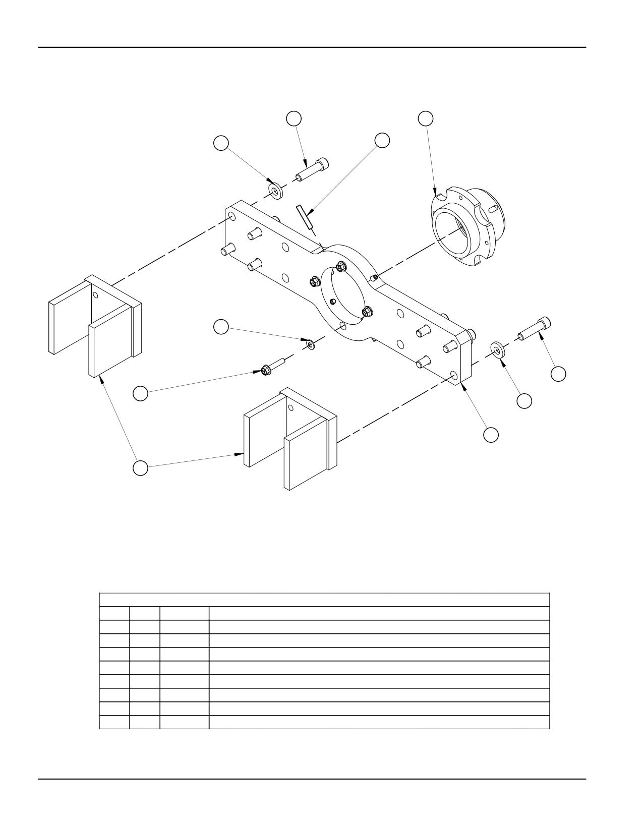
2
5
4
3
1
2
8
3
7
6
PARTS LIST
ITEM
QTY
P/N:
DESCRIPTION
1
4
13489
WASHER 5/16 FLTW SAE
2
8
14036
SCREW 1/2-13 X 2 SHCS
3
8
17145
WASHER 1/2 FLTW HARDENED 1-1/8 OD X 3/16 THK
4
4
20174
SCREW 5/16-18 X 1-3/4 SSSFP
5
1
43264
MOUNT BRG SPHERICAL 1-3/4 ID W/CLAM STD
6
2
43266
PLATE BEARING SCAB
7
1
43277
BRACKET MOUNTING DOUBLE ARM
8
4
45365
SCREW 5/16-24 X 1.500 HHCS FLANGED BLK OX
FIGURE A-11. DOUBLE-ARM BEARING MOUNT ASSEMBLY (P/N 43279)
Page 76
BB4500-BB5000 Operating Manual
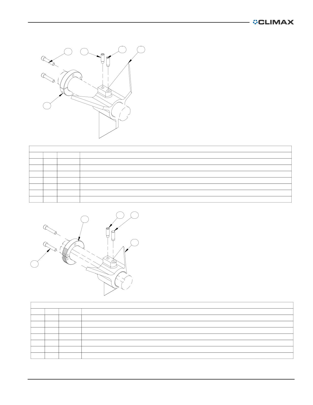
1.2
1.3
2.2
1.1
SET CONES SETUP 6 TO 10 DIA 1-3/4 KEYED BAR
43384
2.1
PARTS LIST
ITEM
QTY
P/N:
DESCRIPTION
1
1
42228
CONE SETUP 6 TO 10 BB4500 1-3/4 BAR
1.1
1
29092
SCREW MOD 3/8-24 X 1-3/16 SSSFD
1.2
1
29091
PIN STOP
1.3
1
42228
CONE SETUP BB4000 6" TO 10"
2
1
42508
CLAMP COLLAR MODIFIED 1 3/4 ID
2.1
1
42508
CLAMP COLLAR MODIFIED
2.2
2
17125
SCREW 5/16-24 X 1-1/2 SHCS
1.1
1.2
2.1
1.3
SET CONES SETUP 2 TO 6 DIA 1-3/4 KEYED BAR
43383
2.2
PARTS LIST
ITEM
QTY
P/N:
DESCRIPTION
1
1
41220
CONE SETUP 2 TO 6 BB4500 1-3/4 BAR
1.1
1
29092
SCREW MOD 3/8-24 X 1-3/16 SSSFD
1.2
1
29091
PIN STOP
1.3
1
41220
CONE SETUP 2" TO 6" BB4000
2
1
42508
CLAMP COLLAR MODIFIED 1 3/4 ID
2.1
1
42508
CLAMP COLLAR MODIFIED
2.2
2
17125
SCREW 5/16-24 X 1-1/2 SHCS
FIGURE A-12. LARGE AND SMALL SET CONES ASSEMBLY (P/N 49060)
P/N 92974, Rev. 3
Page 77
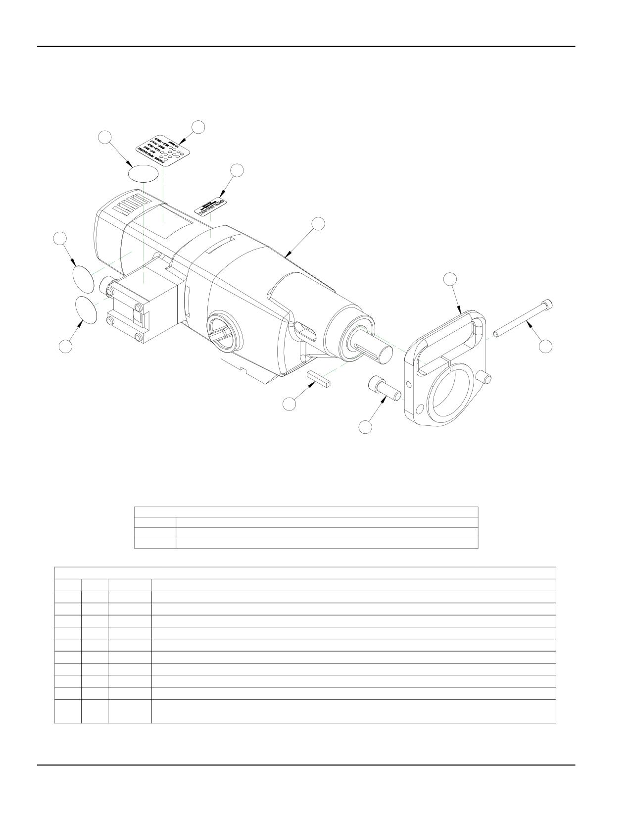
9
6
4
10
8
7
5
1
3
2
AVAILABLE CONFIGURATIONS
PART NO
DESCRIPTION
88008
MOTOR ELECTRIC ASSY EIBENSTOCK 120 V 4 SPEED REVERSIBLE GEN 2
88009
MOTOR ELECTRIC ASSY EIBENSTOCK 230 V 4 SPEED REVERSIBLE GEN 2
PARTS LIST
ITEM
QTY
P/N:
DESCRIPTION
1
1
11873
SCREW 5/16-18 X 3-1/2 SHCS
2
2
12646
SCREW 1/2-13 X 1-1/4 SHCS
3
1
15724
KEY 1/4 SQ X 1.37 SQ BOTH ENDS
4
1
56300
LABEL CLIMAX LOGO .66 X 1.75
5
1
59037
LABEL WARNING - WEAR EAR PROTECTION
6
1
59044
LABEL WARNING - CONSULT OPERATOR'S MANUAL 1.5 DIA
7
1
75648
FLANGE MOTOR MTG ELEC RDU BB5000
8
1
78824
LABEL WARNING - DO NOT EXPOSE TO WATER
9
1
84393
LABEL EIBENSTOCK RPM RANGES
10
1
88004
NFIS MOTOR ELECTRIC 4 SPEED REVERSIBLE 120V CE EIBENSTOCK EAU 34/4.3 CB GEN 2
88005
NFIS MOTOR ELECTRIC 4 SPEED REVERSIBLE 230V CE EIBENSTOCK EAU 34/4.3 CB GEN 2
FIGURE A-13. EIBENSTOCK MOTOR ASSEMBLY (P/N 88012)
Page 78
BB4500-BB5000 Operating Manual
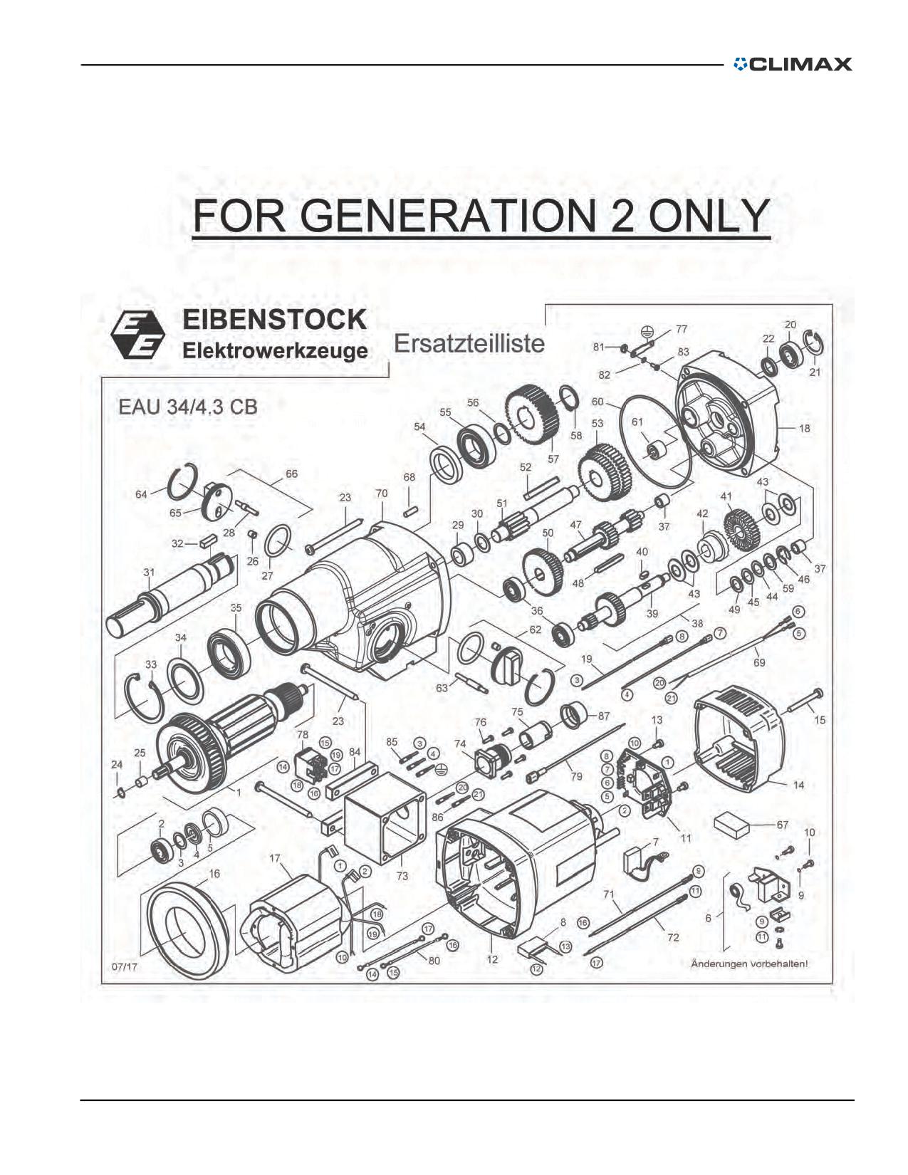
FIGURE A-14. EIBENSTOCK MOTOR ASSEMBLY -- GEN. 2 ONLY
P/N 92974, Rev. 3
Page 79
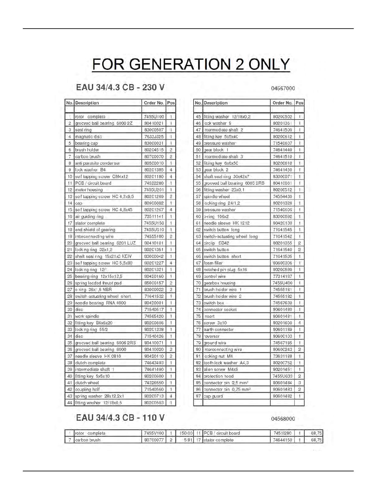
FIGURE A-15. EIBENSTOCK MOTOR ASSEMBLY PARTS LIST -- GEN. 2 ONLY
Page 80
BB4500-BB5000 Operating Manual
TABLE A-1. BB4500 RECOMMENDED SPARE PARTS
Part
Component
Description
Quantity
number
Rotational
12395
Clamp collar
2
drive unit
12436
Leadscrew
1
Leadscrew
assembly
27356
1-5 Acme Nut
2
29552
Clamp collar
2
27015
Shear pin
2
25957
Clutch
4
Axial feed box
assembly
27197
Lead nut
2
92494
Screw assembly, feed stop
2
26850
Crank
1
11734
Screw 3/8-16 X 3/4 SSSCP
4
13356
Screw 5/8-11 X 2-1/2 SHCS
4
Boring head/
bar
11691
Screw 1/2-13 X 1.5 SHCS
2
10191
Screw 3/8-16 X 1 SHCS
2
14036
Screw 1/2-13 x 2 SHCS
8
Spherical
22662
Washer ½
8
bearing
26250
Screw 5/16-24 x 2 HHCS
4
mounting
brackets
21798
Washer 5/16
4
26252
Screw 1/2-20 x 2 SSSFP
4
29840
Hydraulic oil - 76 Unax AW 32 anti-wear fluid
NA
HPU
20273
Key
1
82698
SP brush carbon pair for Eibenstock EAU 34/4.1
2
Electric motor
assembly
26845
3/8 short arm ball driver hex wrench
1
TABLE A-2. BB4500-BB5000 SPARE PARTS KIT (P/N 97276)
Part
Description
Quantity
number
10191
SCREW 3/8-16 X 1 SHCS
2
11691
SCREW 1/2-13 X 1-1/2 SHCS
2
11734
SCREW 3/8-16 X 3/4 SSSCP
4
P/N 92974, Rev. 3
Page 81
TABLE A-2. BB4500-BB5000 SPARE PARTS (CONTINUED)KIT (P/N 97276)
Part
Description
Quantity
number
12395
CLAMP COLLAR SPLIT HINGED 2-1/2 ID (VMI)
4
13356
SCREW 5/8-11 X 2-1/2 SHCS
4
14036
SCREW 1/2-13 X 2 SHCS
8
20273
KEY 1/4 SQ X 1.00 SQ BOTH ENDS (KB)
1
21798
WASHER 5/16 FLTW HARDENED 1/8 THK BLK OX
3
WASHER 1/2 FLTW HARDENED 1-1/8 OD X 1/8 THICK
22662
8
BLACK OXIDE
26250
SCREW 5/16-24 X 2 HHCS
4
26252
SCREW 1/2-20 X 2 SSSFP
4
WRENCH HEX 3/8 SHORT ARM BONDHUS BONDHUS
26845
1
10914 BALLDRIVER
26850
HANDLE CRANK MODIFIED
1
27356
NUT 1-5 ACME 7/8 TALL 1-1/2 HEX FINISHED
2
KIT SERVICE BB5000 BB4500 AFU 3RD GEN COM-
38545
1
PREHENSIVE
SP BRUSH CARBON SINGLE (NOT A PAIR) FOR
82698
EIBENSTOCK EAU 34/4.1 BB4500 BB5000 120V (2
2
WIRES)
82949
BAG TOOL 14 X 5.5 X 6 POLYESTER
1
TABLE A-3. BB4500 TOOL KIT IN INCHES (P/N 43580)
Part
Description
Quantity
number
14251
WRENCH TEE 3/16 HEX (KB)
1
14650
WRENCH END 1/2 COMBINATION LONG
1
25550
WRENCH HEX 5/16 X 11.4 BALLDRIVER T-HANDLE
1
29041
WRENCH END 1-1/2 THIN (SINGLE OPEN END)
1
31858
BIT TOOL HSS 1/2 X 1.8 LH FINISHING SINGLE TC
1
31859
BIT TOOL HSS 1/2 X 4.0 LH FINISHING SINGLE TC
1
31867
BIT TOOL HSS 1/2 X 1.8 LH ROUGHING SINGLE
1
31868
BIT TOOL HSS 1/2 X 4.0 LH ROUGHING SINGLE
1
32342
BIT TOOL HSS 1/2 X 2.5 LH FINISHING SINGLE TC
1
Page 82
BB4500-BB5000 Operating Manual
TABLE A-3. BB4500 TOOL KIT IN INCHES (CONTINUED)(P/N 43580)
Part
Description
Quantity
number
32344
BIT TOOL HSS 1/2 X 2.5 LH ROUGHING SINGLE
1
33784
WRENCH TORX T-27V
1
33999
WRENCH HEX SET .050 - 3/8 BONDHUS BALL END
1
34895
CASE COMPARTMENT 8 X 4-1/8 X 1-3/16
1
44026
PRINT LAYOUT BB4500 PACKAGING
0
55923
WRENCH TEE 1/4 HEX
1
55924
WRENCH 3/8 HEX T-HANDLE
1
60880
HAMMER DEAD BLOW 42OZ
1
82949
BAG TOOL 14 X 5.5 X 6 POLYESTER
1
92974
MANUAL INSTRUCTION BB4500 BB5000 BORING BAR
1
TABLE A-4. BB4500 TOOL KIT IN METRIC (P/N 43582)
Part
Description
Quantity
number
14251
WRENCH TEE 3/16 HEX (KB)
1
14650
WRENCH END 1/2 COMBINATION LONG
1
25550
WRENCH HEX 5/16 X 11.4 BALLDRIVER T-HANDLE
1
29041
WRENCH END 1-1/2 THIN (SINGLE OPEN END)
1
33784
WRENCH TORX T-27V
1
33999
WRENCH HEX SET .050 - 3/8 BONDHUS BALL END
1
34571
BIT TOOL HSS 12MM X 4.0 LH FINISH SINGLE TC
1
34572
BIT TOOL HSS 12MM X 2.5 LH FINISH SINGLE TC
1
34573
BIT TOOL HSS 12MM X 1.8 LH FINISH SINGLE TC
1
34576
BIT TOOL HSS 12MM X 4.0 LH ROUGHING SINGLE
1
34577
BIT TOOL HSS 12MM X 2.5 LH ROUGHING SINGLE
1
34578
BIT TOOL HSS 12MM X 1.8 LH ROUGHING SINGLE
1
34895
CASE COMPARTMENT 8 X 4-1/8 X 1-3/16
1
35516
HAMMER DEAD BLOW 1-3/4 DIA HEAD
1
38678
WRENCH HEX SET 1.5 - 10MM BONDHUS BALL END
1
44026
PRINT LAYOUT BB4500 PACKAGING
0
55923
WRENCH TEE 1/4 HEX
1
P/N 92974, Rev. 3
Page 83
TABLE A-4. BB4500 TOOL KIT IN METRIC (P/N 43582)
Part
Description
Quantity
number
55924
WRENCH 3/8 HEX T-HANDLE
1
82949
BAG TOOL 14 X 5.5 X 6 POLYESTER
1
92974
MANUAL INSTRUCTION BB4500 BB5000 BORING BAR
1
Page 84
BB4500-BB5000 Operating Manual
APPENDIX B BB5000 ASSEMBLY DRAWINGS
Drawing list
FIGURE B-1. AXIAL FEED UNIT ASSEMBLY (P/N 28636)
- - - - - - - - - - - - - - - - - - - - - - - - - - - - - - 86
FIGURE B-2. AXIAL FEED UNIT ASSEMBLY PARTS LIST (P/N 28636) - - - - - - - - - - - - - - - - - - - - - - - - - 87
FIGURE B-3. HD AXIAL FEED UNIT ASSEMBLY (P/N 91518) - - - - - - - - - - - - - - - - - - - - - - - - - - - - - 88
FIGURE B-4. HD AXIAL FEED UNIT ASSEMBLY PARTS LIST (P/N 91518) - - - - - - - - - - - - - - - - - - - - - - - 89
FIGURE B-5. AIR MOTOR CE ASSEMBLY (P/N 28697) - - - - - - - - - - - - - - - - - - - - - - - - - - - - - - - 90
FIGURE B-6. AIR MOTOR CE ASSEMBLY (P/N 28614) - - - - - - - - - - - - - - - - - - - - - - - - - - - - - - - 91
FIGURE B-7. PNEUMATIC CONNECTION ASSEMBLY (P/N 15088)
- - - - - - - - - - - - - - - - - - - - - - - - - - 92
FIGURE B-8. HYDRAULIC MOTOR ASSEMBLY (P/N 39848)
- - - - - - - - - - - - - - - - - - - - - - - - - - - - - 93
FIGURE B-9. SINGLE-ARM MOUNT ASSEMBLY (P/N 37472) - - - - - - - - - - - - - - - - - - - - - - - - - - - - - 94
FIGURE B-10. DOUBLE-ARM MOUNT ASSEMBLY (P/N 37473) - - - - - - - - - - - - - - - - - - - - - - - - - - - - 95
FIGURE B-11. UNIVERSAL BEARING MOUNT ASSEMBLY (P/N 36959)
- - - - - - - - - - - - - - - - - - - - - - - - 96
FIGURE B-12. ID BEARING MOUNT ASSEMBLY (P/N 46293) - - - - - - - - - - - - - - - - - - - - - - - - - - - - - 97
FIGURE B-13. SETUP CONES 2.75-8.37" (70-213 MM) DIAMETER ASSEMBLY (P/N 26507) - - - - - - - - - - - - - - 98
FIGURE B-14. SETUP CONES 8.37-12" (213-305 MM) DIAMETER ASSEMBLY (P/N 26508) - - - - - - - - - - - - - - 99
FIGURE B-15. SERVO DRIVE 460 CE ASSEMBLY (P/N 52876)
- - - - - - - - - - - - - - - - - - - - - - - - - - 100
FIGURE B-16. SERVO DRIVE 460 CE ASSEMBLY PARTS LIST (P/N 52876) - - - - - - - - - - - - - - - - - - - - - 101
FIGURE B-17. RDU 12:1 ASSEMBLY (P/N 53165) - - - - - - - - - - - - - - - - - - - - - - - - - - - - - - - - 102
FIGURE B-18. RDU 12:1 ASSEMBLY PARTS LIST (P/N 53165) - - - - - - - - - - - - - - - - - - - - - - - - - - 103
FIGURE B-19. RDU 4TH GENERATION ASSEMBLY (P/N 49684) - - - - - - - - - - - - - - - - - - - - - - - - - - 104
FIGURE B-20. RDU 4TH GENERATION ASSEMBLY PARTS LIST (P/N 49684)
- - - - - - - - - - - - - - - - - - - - 105
FIGURE B-21. SERVO DRIVE 230V CE ASSEMBLY (P/N 54321)
- - - - - - - - - - - - - - - - - - - - - - - - - 106
FIGURE B-22. SERVO DRIVE 230V CE ASSEMBLY (P/N 54321)
- - - - - - - - - - - - - - - - - - - - - - - - - 107
FIGURE B-23. SERVO MOTOR RDU ADAPTER ASSEMBLY (P/N 51536)
- - - - - - - - - - - - - - - - - - - - - - 108
FIGURE B-24. SERVO MOTOR GUARD ASSEMBLY (P/N 52937) - - - - - - - - - - - - - - - - - - - - - - - - - - 109
FIGURE B-25. SERVO SHROUD FAN ASSEMBLY (P/N 56773) - - - - - - - - - - - - - - - - - - - - - - - - - - - 110
FIGURE B-26. SERVO DRIVE MOTOR 230V NON-CE ASSEMBLY (P/N 71071)
- - - - - - - - - - - - - - - - - - - 111
FIGURE B-27. SERVO DRIVE MOTOR 460V NON-CE ASSEMBLY (P/N 71072)
- - - - - - - - - - - - - - - - - - - 112
FIGURE B-28. EIBENSTOCK MOTOR ASSEMBLY -- GEN. 2 ONLY - - - - - - - - - - - - - - - - - - - - - - - - - - 113
FIGURE B-29. EIBENSTOCK MOTOR ASSEMBLY PARTS LIST -- GEN. 2 ONLY - - - - - - - - - - - - - - - - - - - - - 114
FIGURE B-30. LEADSCREW ASSEMBLY (P/N 28654) - - - - - - - - - - - - - - - - - - - - - - - - - - - - - - - 115
TABLE B-1. BB5000 RECOMMENDED SPARE PARTS - - - - - - - - - - - - - - - - - - - - - - - - - - - - - - - 116
TABLE B-2. BB4500-BB5000 SPARE PARTS KIT (P/N 97276)
- - - - - - - - - - - - - - - - - - - - - - - - - - 117
TABLE B-3. LEADSCREW SPARE PARTS - - - - - - - - - - - - - - - - - - - - - - - - - - - - - - - - - - - - - 117
TABLE B-4. HYDRAULIC METRIC SPARE PARTS - - - - - - - - - - - - - - - - - - - - - - - - - - - - - - - - - - 118
TABLE B-5. BB5000 TOOL KIT IN INCHES (P/N 28784) - - - - - - - - - - - - - - - - - - - - - - - - - - - - - - 119
TABLE B-6. BB5000 TOOL KIT IN METRIC (P/N 34580) - - - - - - - - - - - - - - - - - - - - - - - - - - - - - - 119
P/N 92974, Rev. 3
Page 85
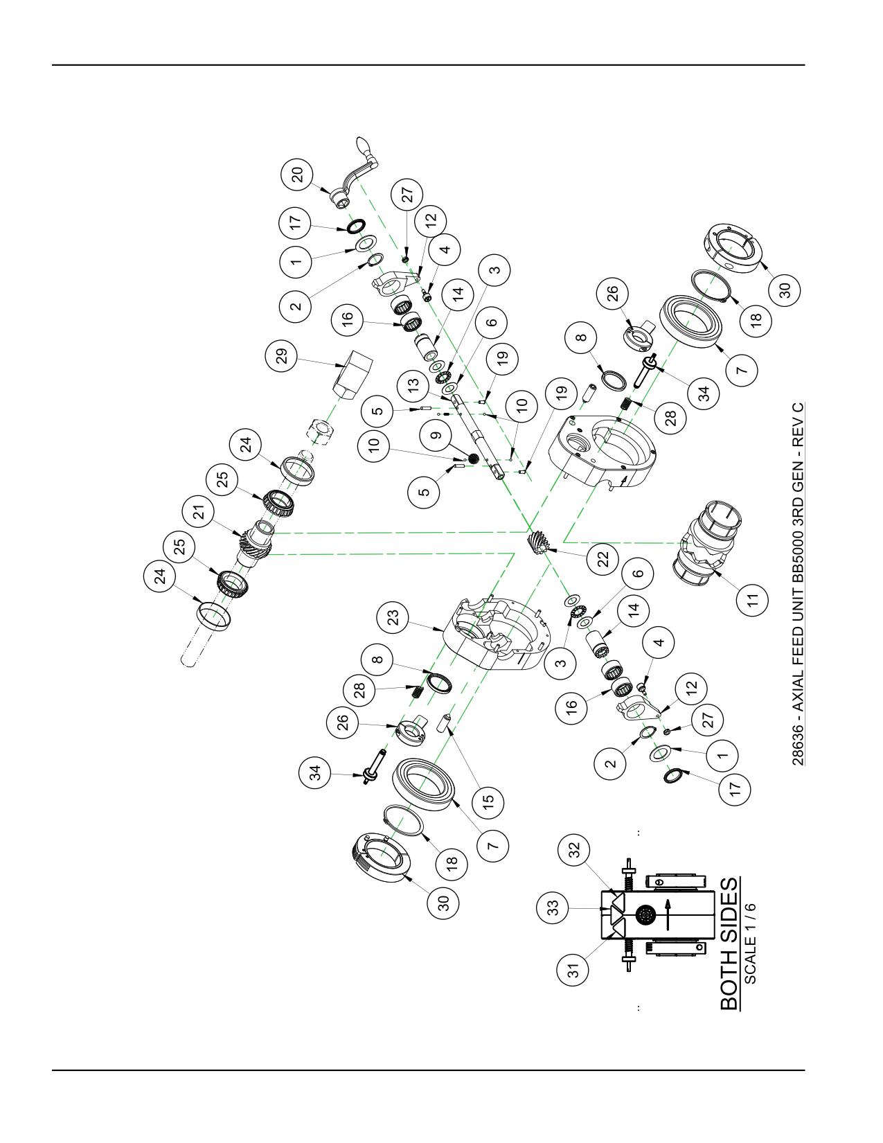
FIGURE B-1. AXIAL FEED UNIT ASSEMBLY (P/N 28636)
Page 86
BB4500-BB5000 Operating Manual
3$576 /,67
,7(0
47<
31
'(6&5,37,21
:$6+(5 7+5867
,' ;
2' ;
5,1* 61$3
2'
%5* 7+5867
,' ;
2' ;
%5* &$0 )2//2:
;
3,1 '2:(/
[
:$6+(5 7+5867
,' ;
2' ;
%5* %$//
;
;
6($/
,' ;
2' ;
.%
635,1* &203
2' ;
:,5( ;
/21* 67$,1/(66
%$// 67((/
',$
&2//(7 $)8 %%
%$5
$50 5$7&+(7
6+$)7 )(('
%86+,1* '5,9(
635,1* 3/81*(5
/,*+7 )25&(
%5* 52//(5 &/87&+
;
;
6($/
,' ;
2' ;
+0
/,3
5,1* 61$3
%(9(/('
3/81*(5 %$// 386+),7
+$1'/( &5$1. 02',),('
/($' 187 %%
%%
$;,$/ )((' 90,
*($5 +(/,&$/ $;,$/ )((' %%
$66(0%/(' $;,$/ )((' 81,7 +286,1*
%5* &83
2' [
:,'(
%5* &21(
,' ;
:,'(
6723
$50
$66<
187
81) .(36
635,1* &203
2' ;
:,5( ;
%/2&. 7$&.:(/' %%
&/$03 &2//$5 02',),('
5' *(1 $)8
/$%(/ :$51,1* +$1' &586+ )25&(
/$%(/ :$51,1* (17$1*/(0(17 2) +$1' 527$7,1* 6+$)7
/$%(/ :$51,1* &877,1* 2) ),1*(56 527$7,1* %/$'( *5$3+,&
7$// 75,$1*/( <(//2:
6&5(: $66< )((' 6723 *(1
FIGURE B-2. AXIAL FEED UNIT ASSEMBLY PARTS LIST (P/N 28636)
P/N 92974, Rev. 3
Page 87
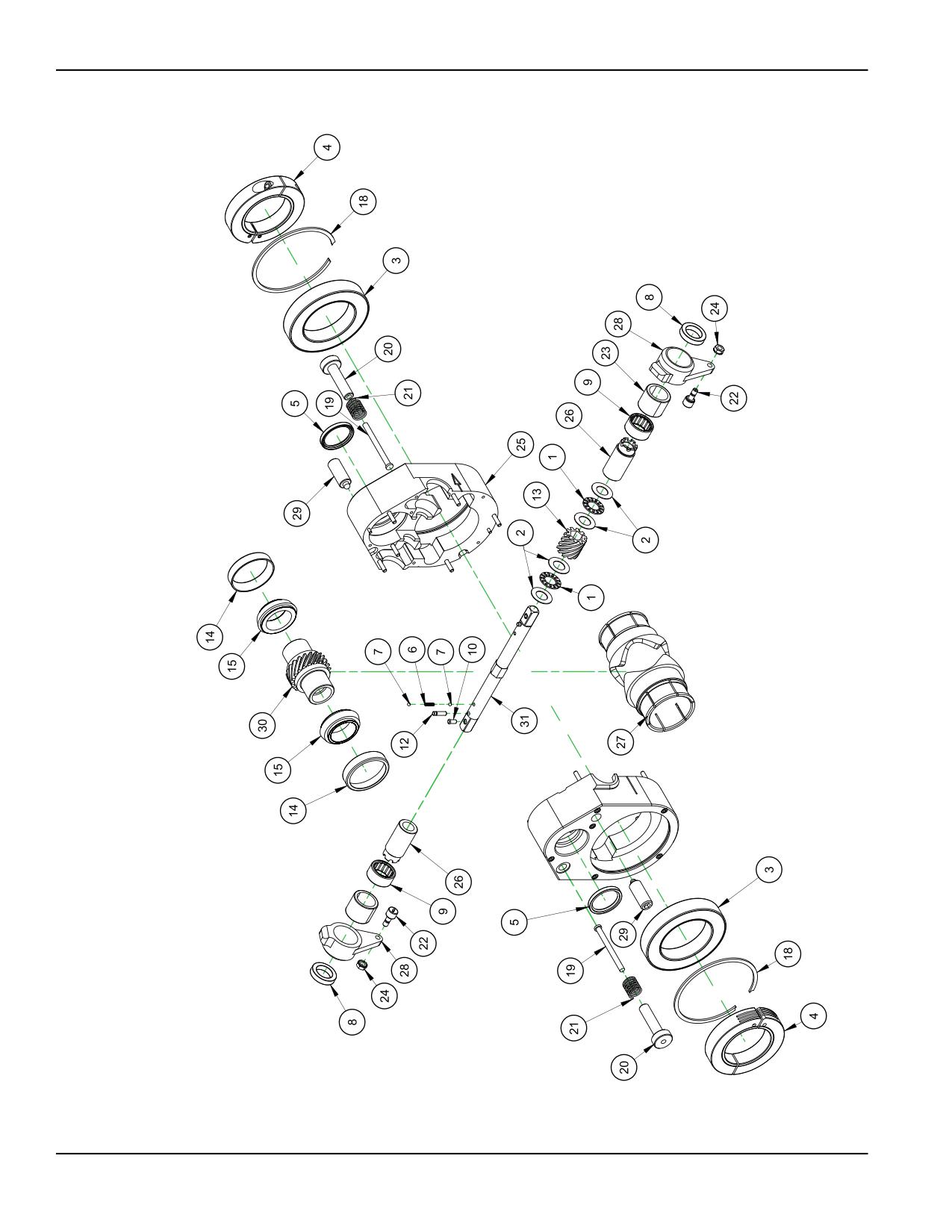
FIGURE B-3. HD AXIAL FEED UNIT ASSEMBLY (P/N 91518)
Page 88
BB4500-BB5000 Operating Manual
PARTS LIST
ITEM
QTY
P/N:
DESCRIPTION
1
2
10538
BRG THRUST .625 ID X 1.125 OD X .0781
2
4
11823
WASHER THRUST .625 ID X 1.125 OD X .030
3
2
12388
BRG BALL 2.7559 X 4.3307 X .7874
4
2
12395
CLAMP COLLAR SPLIT HINGED 2-1/2 ID
5
2
16505
SEAL 1.375 ID X 1.750 OD X .197 (KB)
6
2
19561
SPRING COMP .148 OD X .023 WIRE X .50 LONG STAINLESS
7
4
19562
BALL STEEL 5/32 DIA
8
2
20890
BRG BALL .8750 ID X 1.3125 OD X .281
9
2
25957
BRG ROLLER CLUTCH 1 X 1.312 X .625
10
2
26828
PLUNGER BALL PUSHFIT
11
1
26850
(NOT SHOWN) HANDLE CRANK MODIFIED
12
2
27015
PIN MODIFIED 3/16 x 3/4 GROOVED
13
1
27198
GEAR HELICAL AXIAL FEED BB5000
14
2
27203
BRG CUP 2.328 OD x .470 WIDE
15
2
27204
BRG CONE 1.3775 ID X .66 WIDE
16
1
27222
(NOT SHOWN )STOP ARM ASSY
17
1
28756
(NOT SHOWN) BLOCK TACKWELD BB5000
18
2
43982
RING SNAP 4.331 ID METRIC 110
19
2
49696
CLEVIS STOP PIN
20
2
49697
SCREW 1/2-13 X 3 KHS MOD BB5000 4TH GEN FEED STOP
21
2
49699
SPRING COMP .72 OD X .063 WIRE X .88 LONG
22
2
52347
BRG CAM FOLLOWER .500 OD X .375 WIDE W/ 1/4-28 STUD
23
2
54712
BRG ROLLER CLUTCH 1 ID X 1-5/16 OD X 1.063 SS SPRINGS
24
2
56301
NUT 1/4-28 LOCKING STAR WASHER
25
1
56307
HOUSING AXIAL FEED BB5000 4TH GEN
26
2
56308
BUSHING DRIVE BB5000 4TH GEN
27
1
56309
COLLET AFU BB5000 2-1/4 BAR 4TH GEN
28
2
56310
ARM RATCHET BB5000 4TH GEN
29
2
56314
SPRING PLUNGER 5/8-11 X 1.5 FORCE 3.5 TO 10.5 LBS
30
1
56349
NUT LEAD BB5000 AXIAL FEED
31
1
56380
SHAFT FEED BB5000 4TH GEN PROTOTYPE
FIGURE B-4. HD AXIAL FEED UNIT ASSEMBLY PARTS LIST (P/N 91518)
P/N 92974, Rev. 3
Page 89
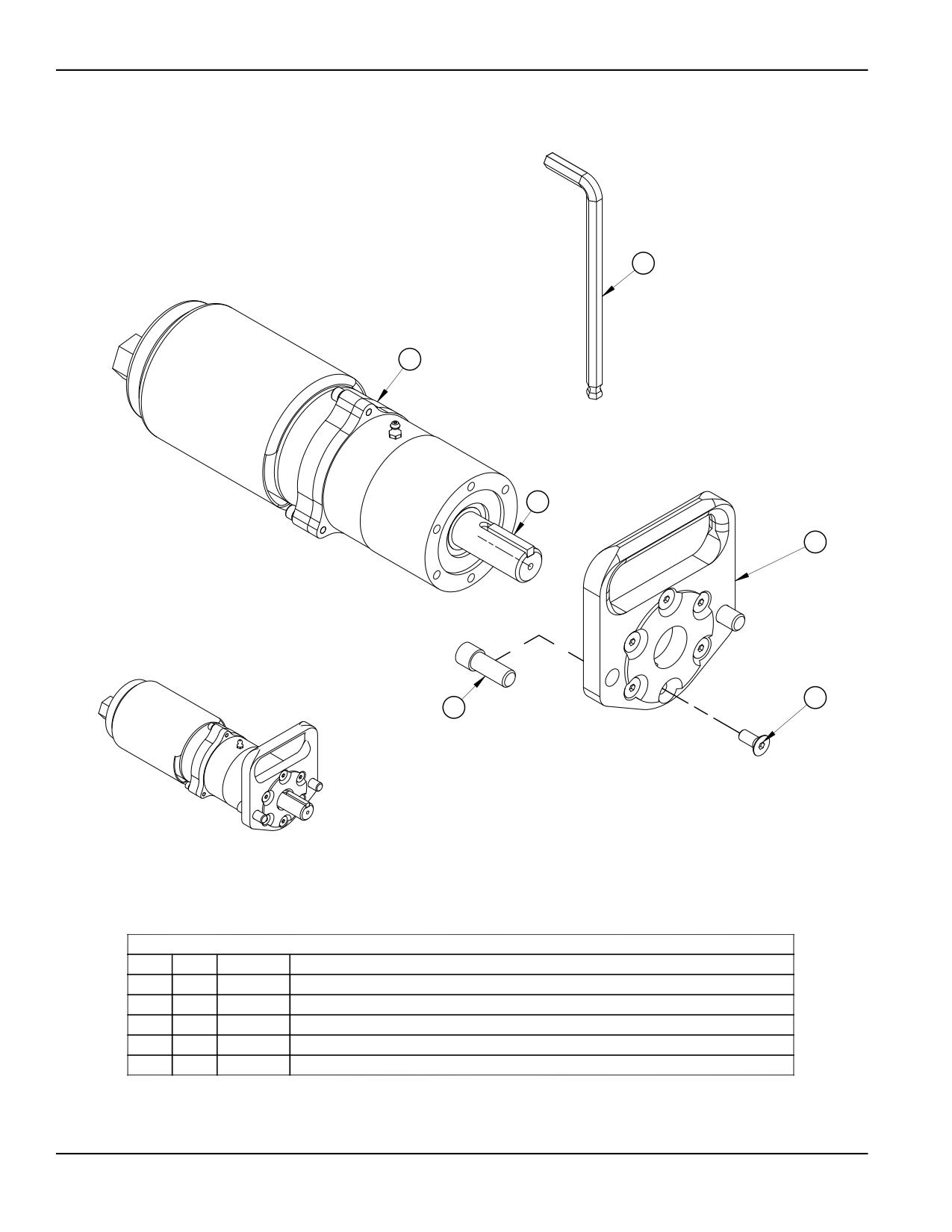
3
2
7
5
1
4
ASSEMBLED
PARTS LIST
ITEM
QTY
P/N:
DESCRIPTION
1
6
10516
SCREW 5/16-18 X 3/4 FHSCS
2
1
15087
MOTOR AIR 3HP 475 RPM FS 228 RPM MAX 93TQ
3
1
26845
WRENCH HEX 3/8 SHORT ARM BONDHUS BALLDRIVER
4
2
28611
SCREW 1/2-13 X 1-1/4 SHCS MODIFIED
5
1
28612
FLANGE MTG AIR MOTOR BB5000
FIGURE B-5. AIR MOTOR CE ASSEMBLY (P/N 28697)
Page 90
BB4500-BB5000 Operating Manual
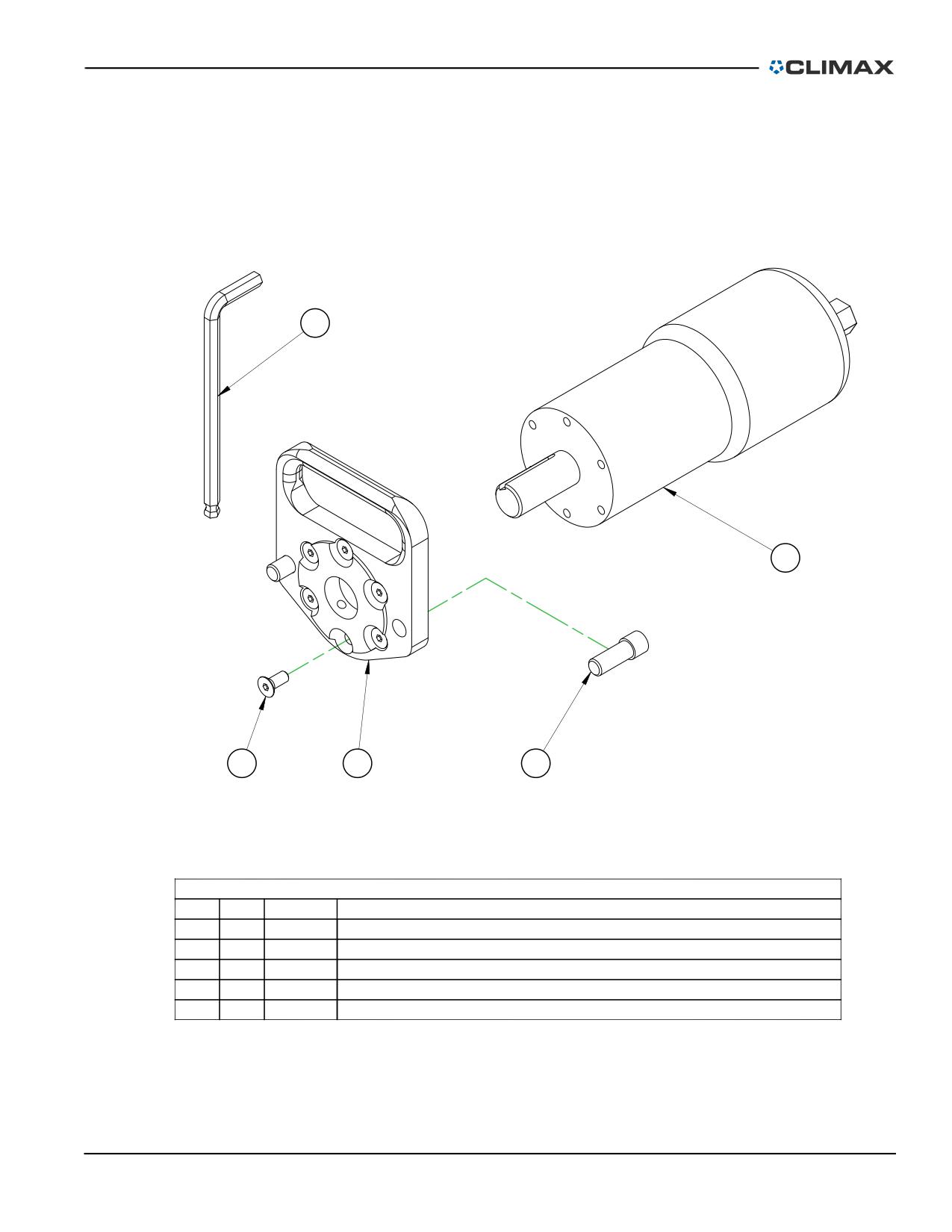
3
2
1
5
4
PARTS LIST
ITEM
QTY
P/N:
DESCRIPTION
1
6
10516
SCREW 5/16-18 X 3/4 FHSCS
2
1
15109
MOTOR AIR 3.2HP 975 RPM FS 485 RPM MAX 47.3TQ
3
1
26845
WRENCH HEX 3/8 SHORT ARM BONDHUS BALLDRIVER
4
2
28611
SCREW 1/2-13 X 1-1/4 SHCS MODIFIED
5
1
28612
FLANGE MTG AIR MOTOR BB5000
FIGURE B-6. AIR MOTOR CE ASSEMBLY (P/N 28614)
P/N 92974, Rev. 3
Page 91
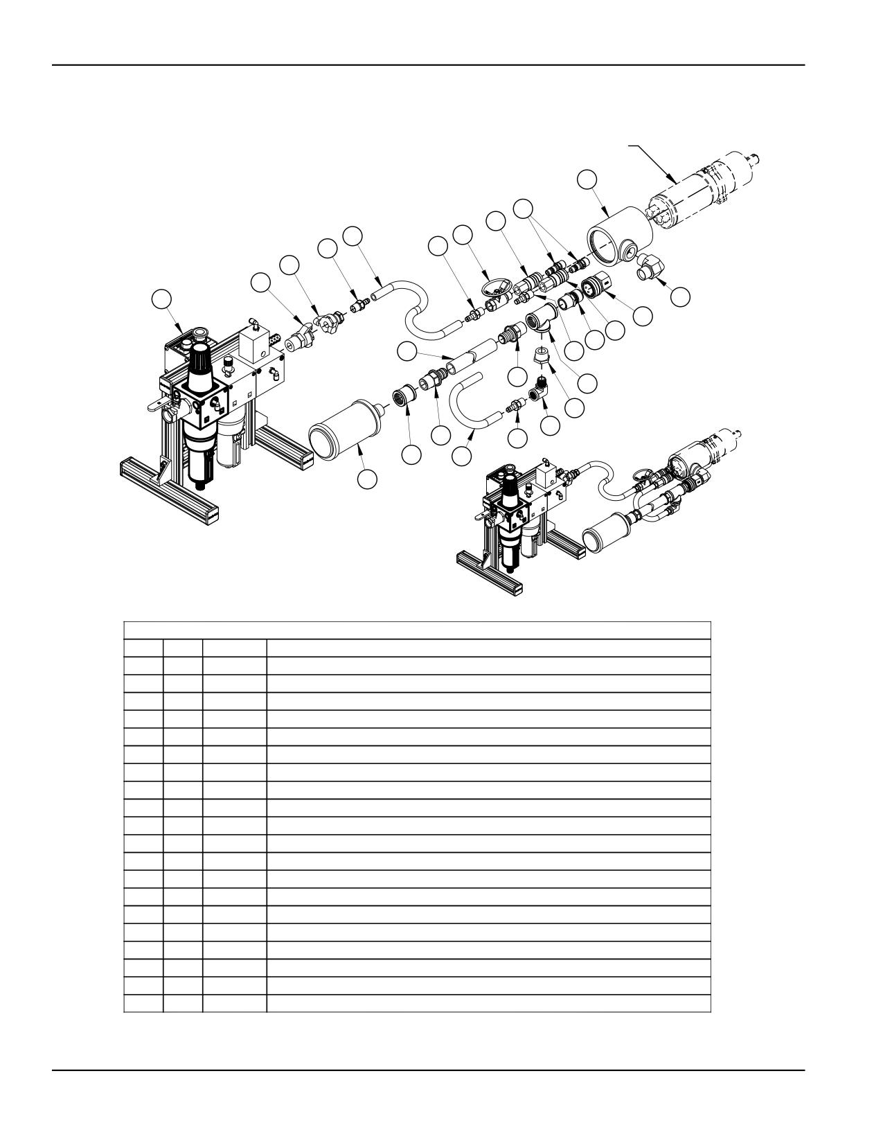
AIR MOTOR
(REFERENCE ONLY)
8
6
5
1
9
3
3
20
18
19
17
11
5
12
16
3
14
13
4
10
14
3
15
2
7
ASSEMBLED
SCALE 1 : 15
PARTS LIST
ITEM
QTY
P/N:
DESCRIPTION
1
70IN
10310
HOSE 801 SERIES PUSHLOK 1/2
2
16IN
10310
HOSE 801 SERIES PUSHLOK 1/2
3
4
10311
FTG BARB 1/2 NPTM X 1/2 HOSE
4
1
10321
FTG REDUCER BUSHING 1 NPTM X 1/2NPTF
5
2
13208
FTG QUICK COUPLER 1/2B 1/2NPTF FEMALE AIR
6
2
13209
FTG QD NIPPLE 1/2B 1/2 NPTM PNEUMATIC
7
1
15243
MUFFLER AIR MOTOR
8
1
19730
EXHAUST DEFLECTOR
9
1
35667
VALVE BALL 1/2 NPTM X 1/2 NPTF OVAL HANDLE
10
1
35692
FTG ELBOW 1/2 NPTM X 1/2 NPTF ST 90 DEG BRASS
11
1
55800
FTG QUICK COUPLER 1B 1 NPTF FEMALE AIR BRASS
12
1
55801
FTG QUICK COUPLER 1B 1 NPTM MALE AIR NON-VALVED BRASS
13
1
55802
FTG TEE 1 NPTF (3) BRASS
14
2
55803
FTG BARB 1 NPTM X 1 HOSE BRASS
15
1
55804
FTG CONNECTOR 1 NPTF X 1NPTF BRASS
16
60IN
55805
HOSE PUSH LOK 801 X 1 GREY
17
1
55832
FTG ELBOW 1 NPTM X 1 NPTM 90 DEG
18
1
58380
FTG QUICK COUPLER UNIVERSAL 1 NPTM
19
1
59248
PNEUMATIC CONDITIONING UNIT 1 IN W/ L.P. DROP OUT AND E-STOP CE
20
1
62564
FTG QUICK COUPLER UNIVERSAL 1/2 NPTF
FIGURE B-7. PNEUMATIC CONNECTION ASSEMBLY (P/N 15088)
Page 92
BB4500-BB5000 Operating Manual
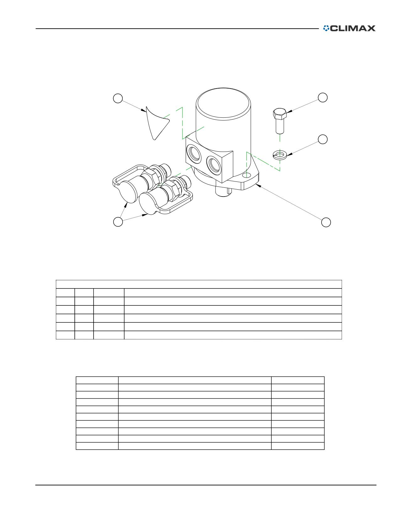
5
2
1
4
3
PARTS LIST
ITEM
QTY
P/N:
DESCRIPTION
1
2
11238
WASHER LOCK 1/2
2
2
11826
SCREW 1/2-13 X 1-1/4 HHCS
3
1
A/R
SEE CHART
4
1
39828
KIT FTG 1/2 HYD QUICK COUPLERS
5
1
78619
LABEL WARNING HOT SURFACE GRAPHIC 1.95" TALL TRIANGLE YELLOW (KB)
PART No
DESCRIPTION
MOTOR HYD P/N
39837
MOTOR ASSY HYD 2.2 CU IN KEYED 1/2 FTG
27477
39843
MOTOR ASSY HYD 3.6 CU IN KEYED 1/2 FTG
20684
39844
MOTOR ASSY HYD 5.7 CU IN KEYED 1/2 FTG S-SERIES
21530
39845
MOTOR ASSY HYD 7.3 CU IN KEYED 1/2 FTG
20231
39846
MOTOR ASSY HYD 8.9 CU IN KEYED S-SERIES 1/2 FTG
21531
39847
MOTOR ASSY HYD 14.1 CU IN KEYED 1/2 FTG
34585
43451
MOTOR ASSY HYD 11.3 CU IN KEYED 1/2 FTG
21532
43452
MOTOR ASSY HYD 17.9 CU IN KEYED 1/2 FTG
21534
43552
MOTOR ASSY HYD 22.5 CU IN KEYED SHAFT
30567
FIGURE B-8. HYDRAULIC MOTOR ASSEMBLY (P/N 39848)
P/N 92974, Rev. 3
Page 93
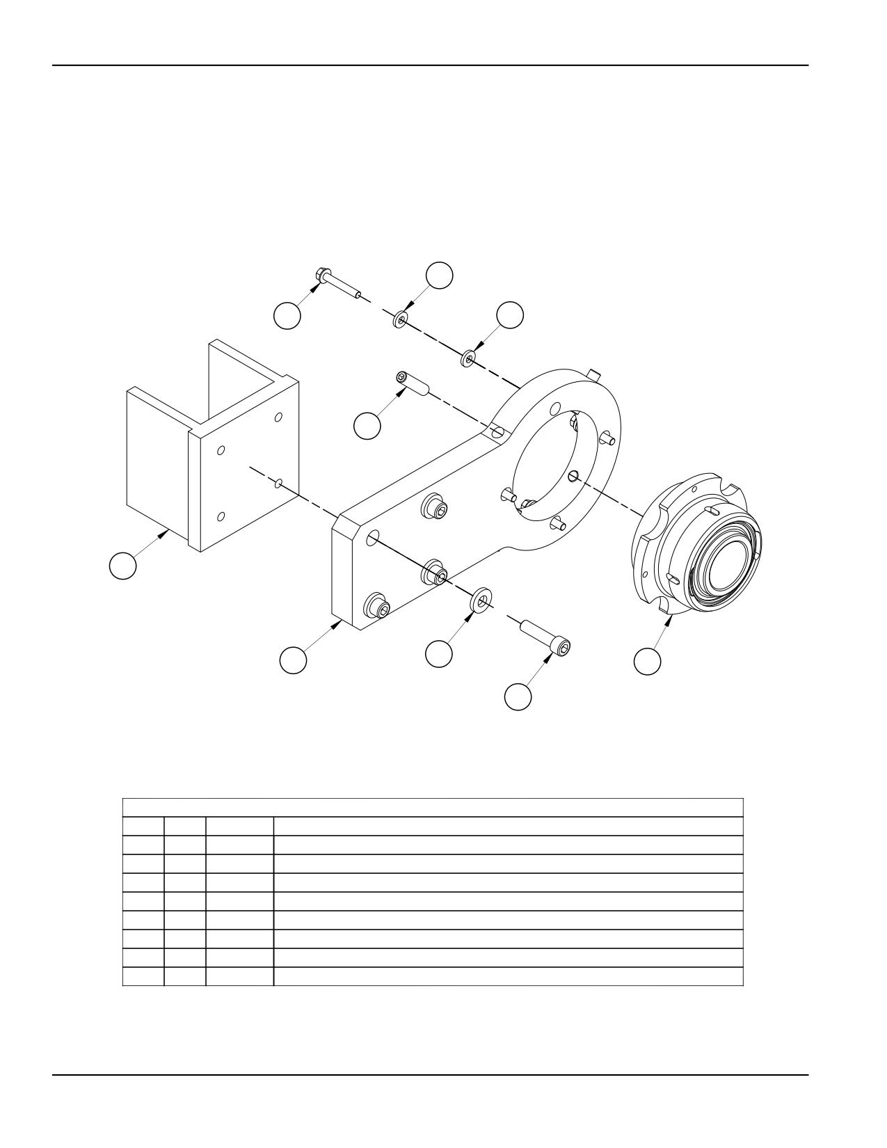
4
8
4
7
3
2
6
5
1
PARTS LIST
ITEM
QTY
P/N:
DESCRIPTION
1
4
14036
SCREW 1/2-13 X 2 SHCS
2
4
17145
WASHER 1/2 FLTW HARDENED 1-1/8 OD X 3/16 THK
3
1
19869
PLATE SPACER TACK WELD MTG
4
8
21798
WASHER 5/16 FLTW HARDENED
5
1
26248
ASSY BRG SPHERICAL 2-1/4 ID W/ CLAMP COLLAR
6
1
26251
BRACKET MTG SPHERICAL BRG 1-ARM
7
4
26252
SCREW 1/2-20 X 2 SSSFP
8
4
45364
SCREW 5/16-24 X 2 HHCS FLANGED BLK OX
FIGURE B-9. SINGLE-ARM MOUNT ASSEMBLY (P/N 37472)
Page 94
BB4500-BB5000 Operating Manual
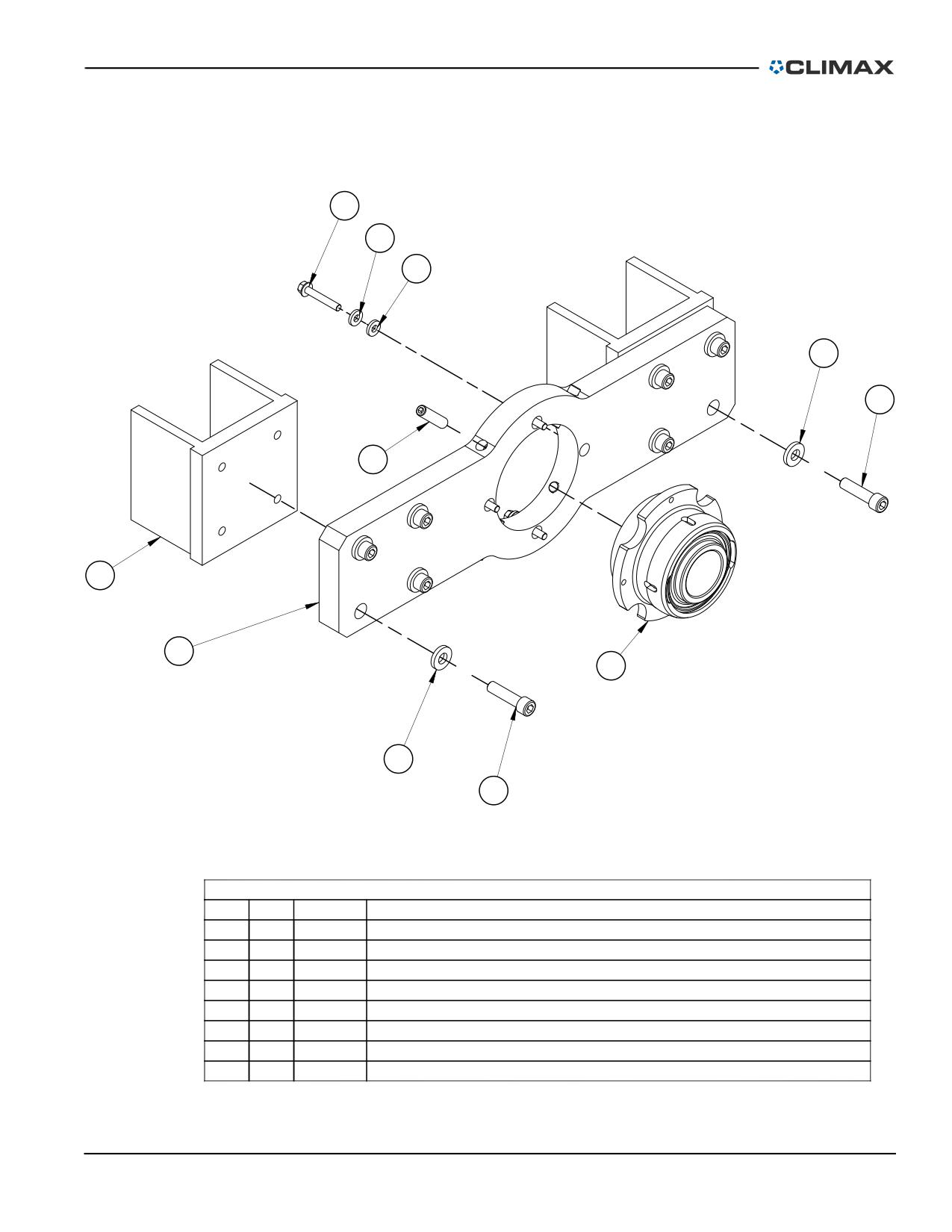
8
4
4
2
1
6
3
7
5
2
1
PARTS LIST
ITEM
QTY
P/N:
DESCRIPTION
1
8
14036
SCREW 1/2-13 X 2 SHCS
2
8
17145
WASHER 1/2 FLTW HARDENED 1-1/8 OD X 3/16 THK
3
2
19869
PLATE SPACER TACK WELD MTG
4
8
21798
WASHER 5/16 FLTW HARDENED
5
1
26248
ASSY BRG SPHERICAL 2-1/4 ID W/ CLAMP COLLAR
6
4
26252
SCREW 1/2-20 X 2 SSSFP
7
1
26517
MTG BRACKET SPHERICAL BRG 2-ARM
8
4
45364
SCREW 5/16-24 X 2 HHCS FLANGED BLK OX
FIGURE B-10. DOUBLE-ARM MOUNT ASSEMBLY (P/N 37473)
P/N 92974, Rev. 3
Page 95
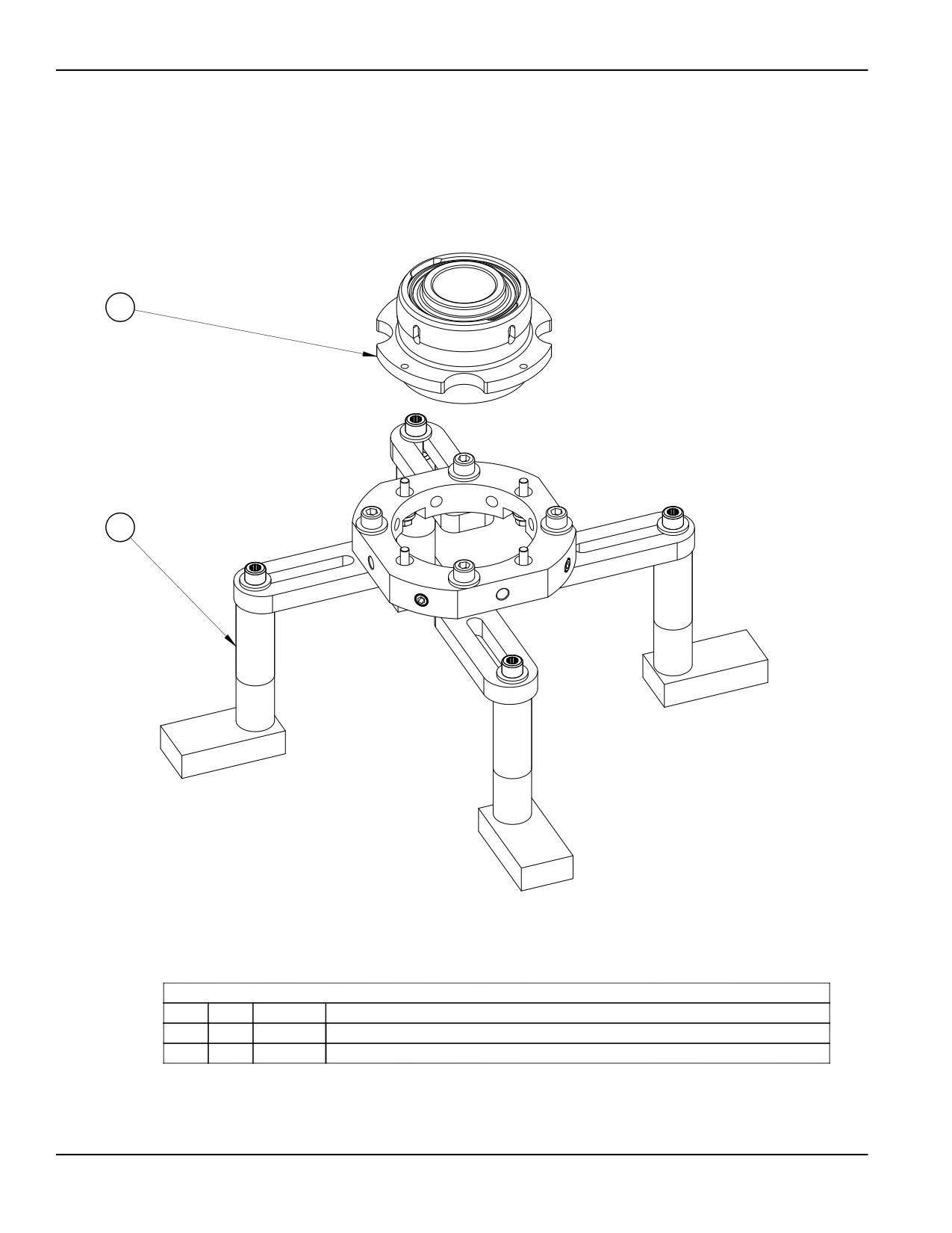
1
2
PARTS LIST
ITEM
QTY
P/N:
DESCRIPTION
1
1
26248
ASSY BRG SPHERICAL 2-1/4 ID W/ CLAMP COLLAR
2
1
41514
MOUNT UNIVERSAL BORING BARS BB5000 NO BEARING
FIGURE B-11. UNIVERSAL BEARING MOUNT ASSEMBLY (P/N 36959)
Page 96
BB4500-BB5000 Operating Manual
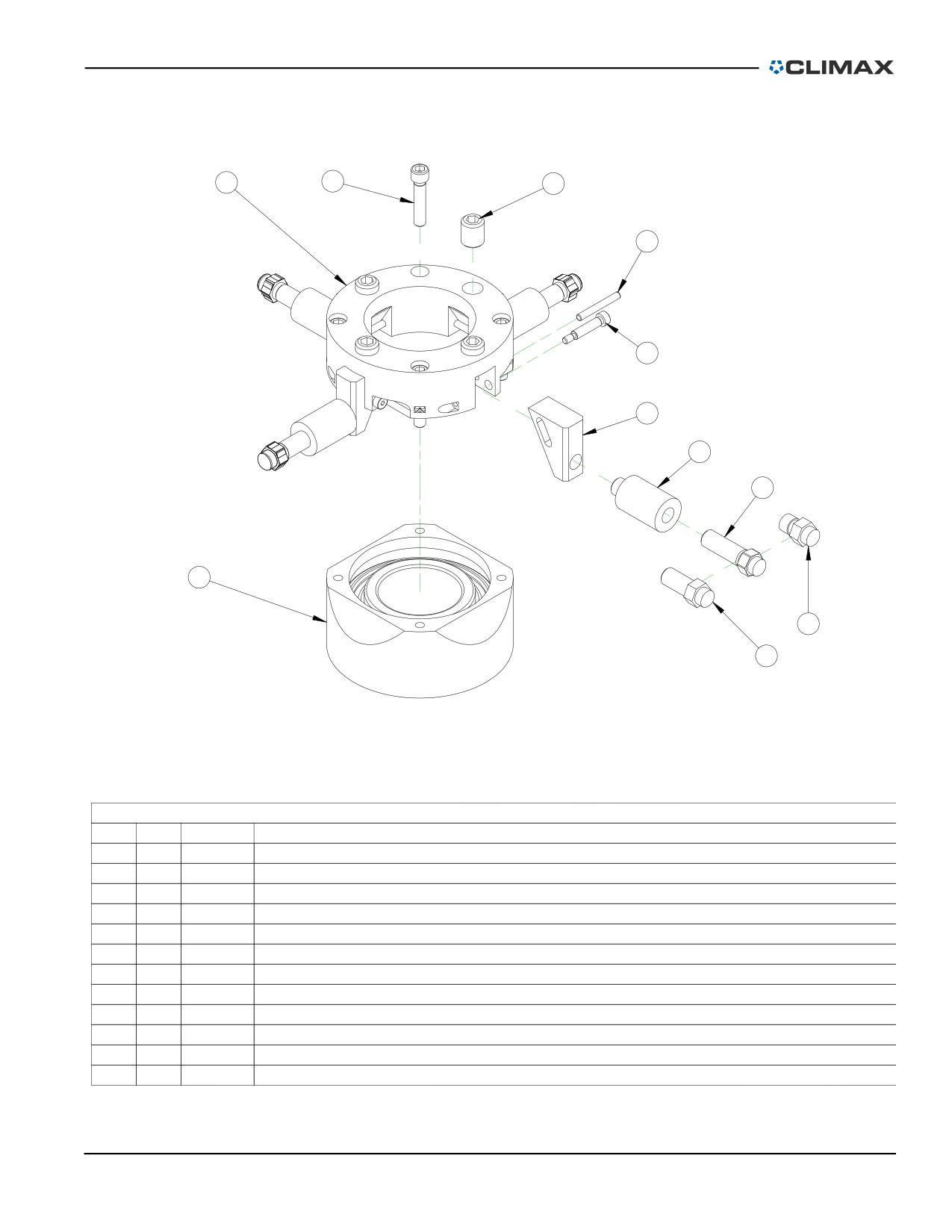
7
1
2
3
10
6
9
5
8
11
4
PARTS LIST
ITEM
QTY
P/N:
DESCRIPTION
1
4
11741
SCREW 5/16-18 X 1-1/2 SHCS
2
4
12563
SCREW 5/8-18 X 3/4 SSSFP
3
4
35600
PIN DOWEL 3/16 DIA X 1-1/2
4
4
37618
BOLT JACKING 1 ID BRG MOUNT
5
4
37619
BOLT JACKING 1/2-20 X 1-1/2 ID BEARING MOUNT
6
4
46216
30 DEGREE SLIDE
7
1
46218
PLATE FACE ADJUST
8
1
46219
HOUSING MOUNT ID BRG BB5000
9
4
46227
1.5 INCH CHUCK JAW (KB)
10
4
46294
SCREW 1/4 DIA X 1 X 10-24 SHLDCS
11
4
46303
BOLT JACKING 1/2 ID BRG MOUNT
12
1
46589
(NOT SHOWN) MANUAL INSTRUCTION BB5000 ID BEARING MOUNT
FIGURE B-12. ID BEARING MOUNT ASSEMBLY (P/N 46293)
P/N 92974, Rev. 3
Page 97
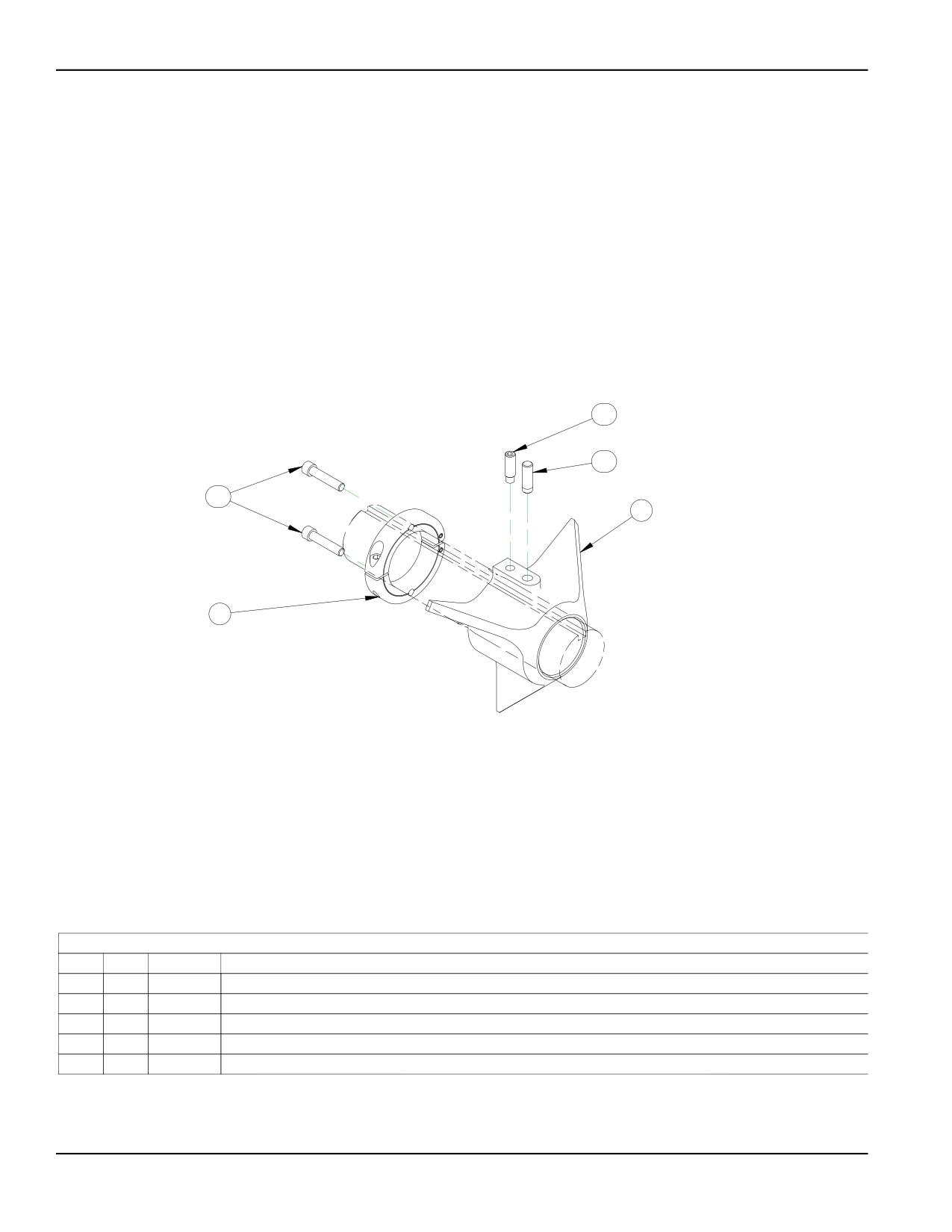
1.1
1.2
3.1
1
3
PARTS LIST
ITEM
QTY
P/N:
DESCRIPTION
1
1
26380
CONE SETUP Ø2.75 TO Ø8.37 BB5000
1.1
1
29092
SCREW MOD 3/8-24 X 1-3/16 SSSFD
1.2
1
29091
PIN STOP
3
1
29095
CLAMP COLLAR MODIFIED
3.1
2
17125
SCREW 5/16-24 X 1-1/2 SHCS
FIGURE B-13. SETUP CONES 2.75-8.37" (70-213 MM) DIAMETER ASSEMBLY (P/N 26507)
Page 98
BB4500-BB5000 Operating Manual
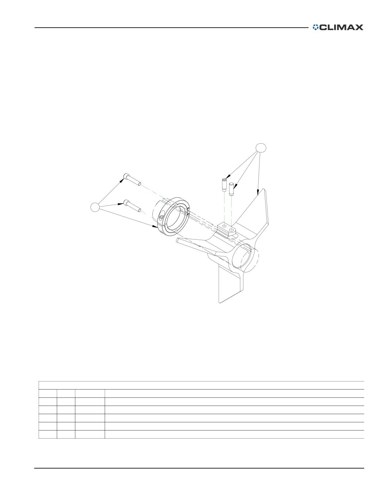
2.1
3
PARTS LIST
ITEM
QTY
P/N:
DESCRIPTION
2
1
26382
CONE SETUP 8.37 TO 12.0 DIA BB5000
2.1
1
29092
SCREW MOD 3/8-24 X 1-3/16 SSSFD
2.2
1
29091
PIN STOP
3
1
29095
CLAMP COLLAR MODIFIED
3.1
2
17125
SCREW 5/16-24 X 1-1/2 SHCS
FIGURE B-14. SETUP CONES 8.37-12" (213-305 MM) DIAMETER ASSEMBLY (P/N 26508)
P/N 92974, Rev. 3
Page 99
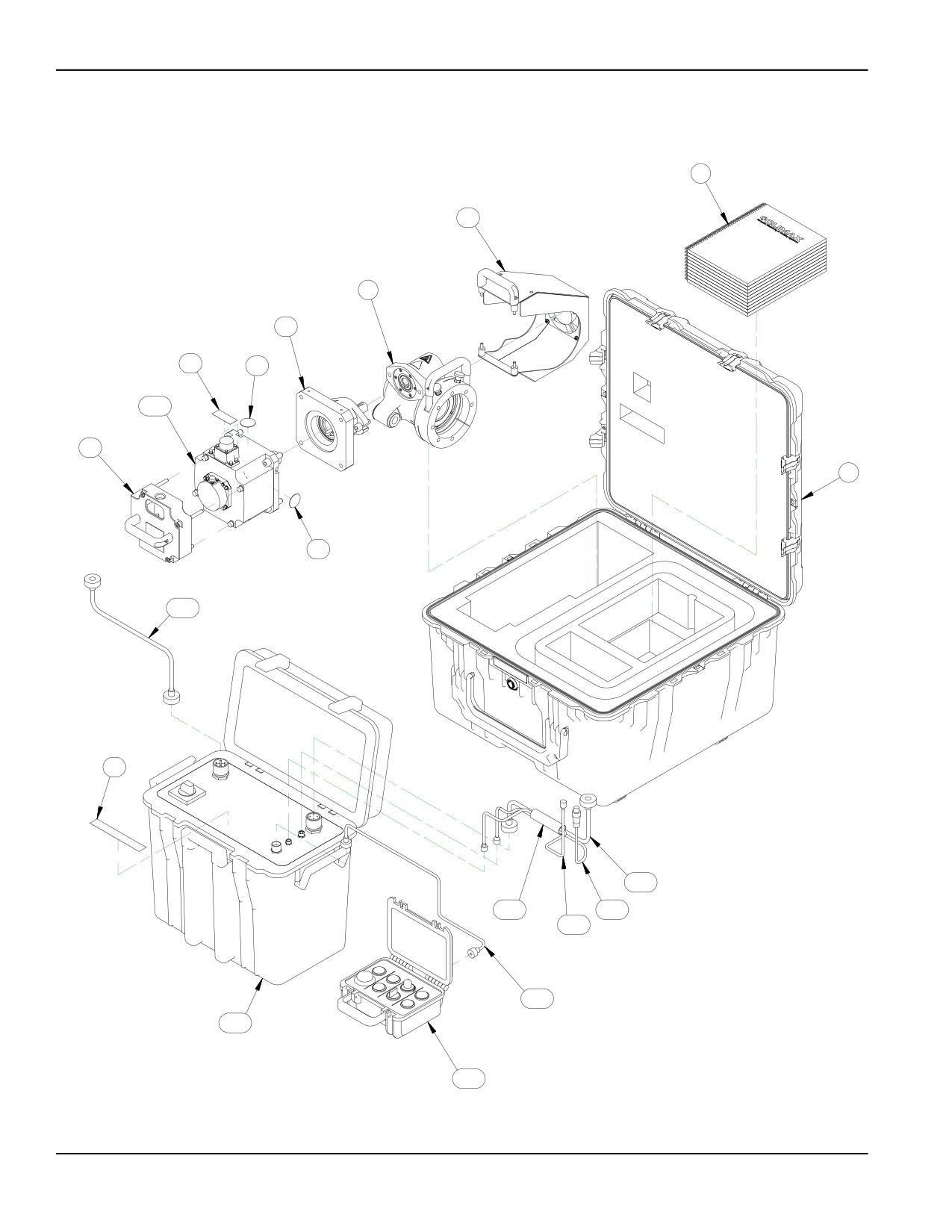
6
5.6
3
5.1
5.4
5.3
5.7.5
5.2
2
5.3
5.7.4
5.5
5.7.8
5.7.2
5.7.3
5.7.7
5.7.6
5.7.9
5.7.1
FIGURE B-15. SERVO DRIVE 460 CE ASSEMBLY (P/N 52876)
Page 100
BB4500-BB5000 Operating Manual
PARTS LIST
ITEM
QTY
P/N:
DESCRIPTION
1
1
26845
(NOT SHOWN) WRENCH HEX 3/8 SHORT ARM BONDHUS BONDHUS 10914 BALLDRIVER
2
1
52188
ASSY SHIPPING CASE WITH CUT FOAM FOR BB5000 SERVO PACKAGE
3
1
53165
RDU 12:1 BB5000 4TH GEN
4
1
55583
LAMINATED PENDANT INSTRUCTION (NOT SHOWN)
5
1
56027
SERVO DRIVE MOTOR ASSEMBLY 460V 4TH GEN
5.1
1
51536
ADAPTER BB5000 RDU TO SERVO MOTOR
5.2
1
52937
GUARD ASSY BB5000 SERVO MOTOR
5.3
2
53464
LABEL WARNING HOT HAND
5.4
1
53482
LABEL WARNING VOLTAGE
5.5
1
53483
LABEL WARNING VOLTAGE CABLE
5.6
1
56773
ASSY FAN & SHROUD BB5000 SERVO ASSY
5.7
1
96888
ASSY BB5000 SERVO DRIVE 460VAC CONTROLS MOTOR AND CABLES CE 4TH GEN
5.7.1
1
53263
PENDANT BB5000 SERVO DRIVE
5.7.2
120
56269
SLEEVE WELD COVER 1" DIA STRAIGHTLINE W/VELCRO CLOSURE (10 FT)
5.7.3
1
57016
ASSY CABLE FAN BB5000 SERVO DRIVE 242 IN LONG
5.7.4
1
66908
ASSY CORDSET BB5000 SERVO INCOMING POWER CABLE 90 DEG CONN LONG 2ND GEN
5.7.5
1
91716
SERVO MOTOR MODEL HG-SR 3.5 kW 2000 RPM 400V KEYED SHAFT
5.7.6
1
96884
CORDSET OPERATOR PENDANT BB5000 SERVO DRIVE 5M LONG 4TH GEN
5.7.7
1
96885
ASSY ENCODER CABLE BB5000 SERVO DRIVE 6 M LONG 4TH GEN
5.7.8
1
96886
ASSY CABLE BB5000 SERVO POWER CABLE 90 DEG CONN 6M LONG 4TH GEN
5.7.9
1
96887
ASSY CONTROLLER SERVO DRIVE BB5000 460/3/50-60 CE 4TH GEN
6
1
92974
MANUAL INSTRUCTION BB45000 BB5000 BORING BAR
FIGURE B-16. SERVO DRIVE 460 CE ASSEMBLY PARTS LIST (P/N 52876)
P/N 92974, Rev. 3
Page 101
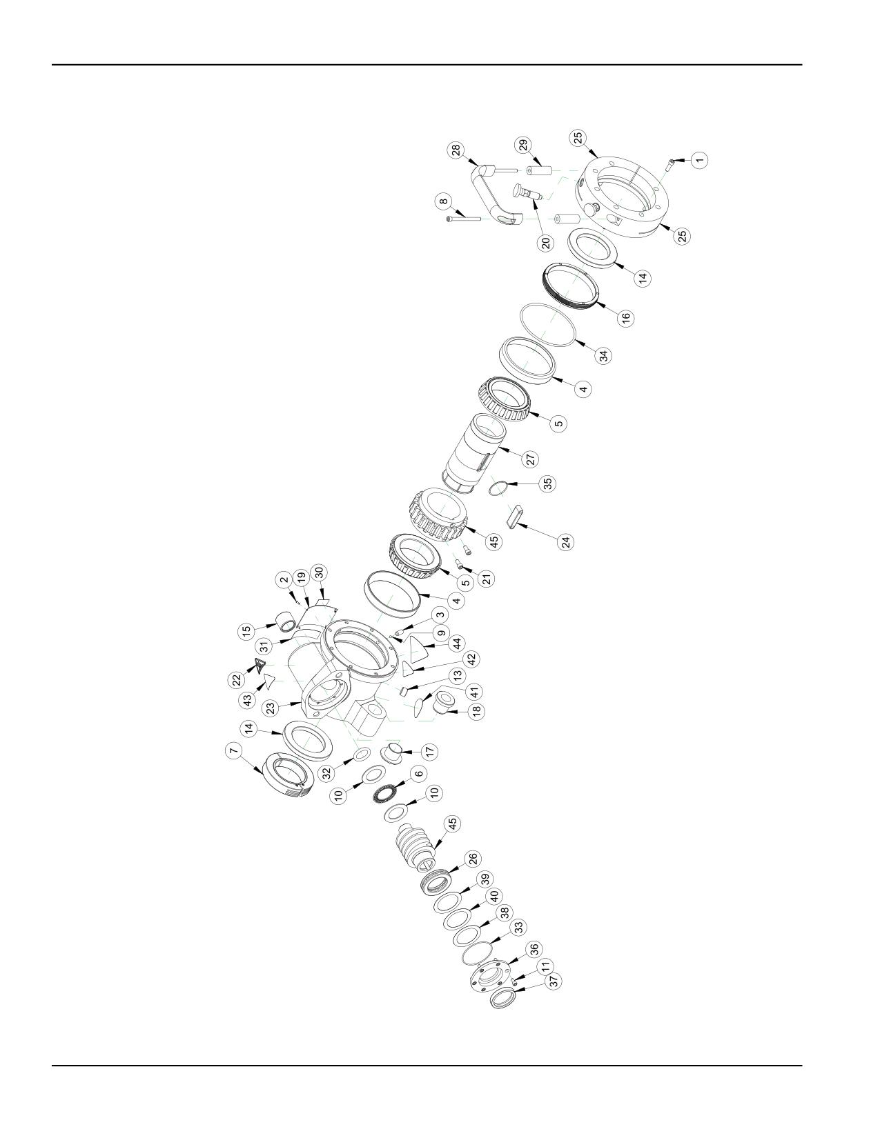
FIGURE B-17. RDU 12:1 ASSEMBLY (P/N 53165)
Page 102
BB4500-BB5000 Operating Manual
PARTS LIST
ITEM
QTY
P/N:
DESCRIPTION
1
7
10160
SCREW 1/4-20 X 3/4 SHCS
2
4
10588
SCREW DRIVE #2 x 1/4 HOLE SIZE .089
3
2
11684
SCREW 5/16-18 X 3/4 SSSCP
4
2
11821
BRG CUP 4.4375 OD X .750 WIDE
5
2
11822
BRG CONE 2.75 ID X 1.00 WIDE
6
1
12387
BRG THRUST 1.259 ID X 1.937 OD X .0781
7
1
12395
CLAMP COLLAR SPLIT HINGED 2-1/2 ID
8
2
12592
SCREW 1/4-20 X 2-3/4 SHCS
9
2
16594
BALL NYLON 3/16 DIA
10
2
16666
WASHER THRUST 1.250 ID X 1.937 OD X .060
11
6
19232
SCREW 10-24 X 3/8 SHCS
12
1
19610
SCREW 5/8-18 X 2-1/4 SHCS
13
1
21956
FTG PLUG 3/8 NPTM SOCKET
14
2
27348
SEAL 2.75 X 4.00 X .375
15
1
27353
BRG NEEDLE 1 ID X 1-1/4 OD X 1 CLOSED
16
1
28219
NUT MAIN BRG PRELOAD
17
1
28220
BUSHING LEADSCREW FLANGED
18
1
28589
BUSHING FLANGED 1 5P ACME THREADED
19
1
29154
PLATE SERIAL YEAR MODEL CE 2.0 X 3.0 (KB)
20
2
29207
SPRING PLUNGER HAND RETRACT 1/2 X 13
21
2
45900
SCREW 1/4-28 X 1/2 SHCS
22
1
46902
LABEL WARNING HOT SURFACE GRAPHIC 1.13" TALL
23
1
49665
HOUSING RDU BB5000 4TH GEN
24
1
49666
KEY MAIN DRIVE BB5000 4TH GEN
25
1
52303
CLAMP RING RDU MOUNT BB5000 4TH
26
1
52307
BRG BALL THRUST 40 MM ID X 60 MM OD X 13 MM
27
1
53168
COLLET MAIN DRIVE BB5000 4TH GEN
28
1
53610
HANDLE PULL 1/4 CBORE MTG 2.17 X 5.75 X 1.02W COATED
29
2
53613
SPACER .67 OD X .266 ID X 1.875 LG
30
1
54131
LABEL "12:1"
31
1
54133
LABEL OIL RDU
32
1
54916
RING O 3/16 X 1 ID X 1-3/8 OD VITON 75 DUROMETER
33
1
54920
RING O 1/16 X 2-1/4 ID X 2-3/8 OD
34
1
54921
RING O 4-3/8 ID X 4-5/8 OD X 1/8
35
1
54922
RING O 1/16 X 1-3/8 ID X 1-1/2 OD VITON 75 DUROMETER
36
1
55090
CAP WORM HOUSING 12:1 RDU BB5000
37
1
55708
SEAL 1.500 ID X 2.000 OD X .375 HIGH TEMP
38
A/R
55784
SHIM 1.7 ID X 2.3 OD .001 THICK
39
A/R
55790
SHIM 1.7 ID X 2.3 OD .002 THICK
40
A/R
55791
SHIM 1.7 ID X 2.3 OD .005 THICK
41
1
59044
LABEL WARNING - CONSULT OPERATOR'S MANUAL
45
1
78688
SET WORM GEAR 12:1 BB5000 4TH GEN 1PC WORM
42
1
78741
LABEL WARNING CRUSH FOOT
43
1
78748
LABEL WARNING FLYING DEBRIS/LOUD NOISE
44
1
80207
LABEL WARNING - ENTANGLEMENT/ROTATING SHAFT GRAPHIC 1.95 TALL TRIANGLE YELLOW
FIGURE B-18. RDU 12:1 ASSEMBLY PARTS LIST (P/N 53165)
P/N 92974, Rev. 3
Page 103
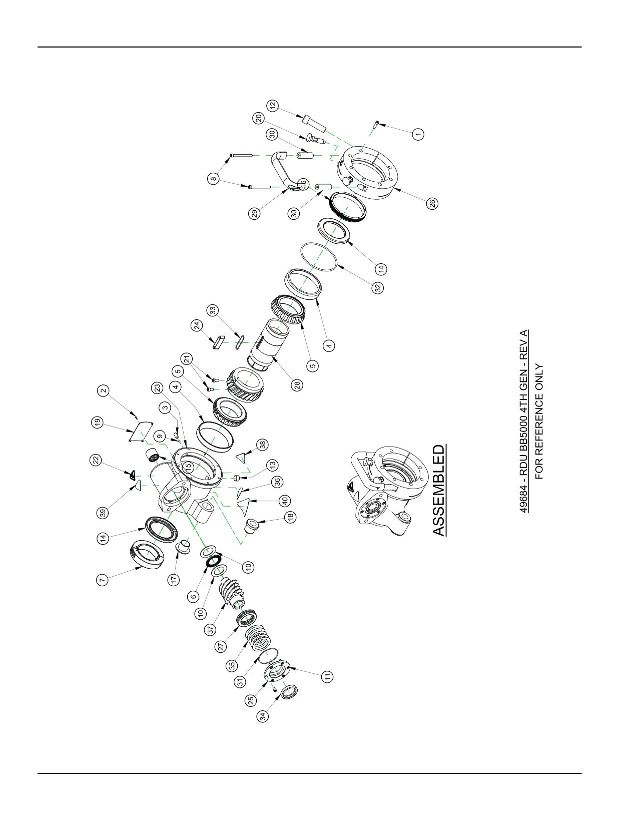
FIGURE B-19. RDU 4TH GENERATION ASSEMBLY (P/N 49684)
Page 104
BB4500-BB5000 Operating Manual
PARTS LIST
ITEM
QTY
P/N:
DESCRIPTION
1
7
10160
SCREW 1/4-20 X 3/4 SHCS
2
4
10588
SCREW DRIVE #2 x 1/4 HOLE SIZE .089
3
2
11684
SCREW 5/16-18 X 3/4 SSSCP
4
2
11821
BRG CUP 4.4375 OD X .750 WIDE
5
2
11822
BRG CONE 2.75 ID X 1.00 WIDE
6
1
12387
BRG THRUST 1.259 ID X 1.937 OD X .0781
7
1
12395
CLAMP COLLAR SPLIT HINGED 2-1/2 ID
8
2
12592
SCREW 1/4-20 X 2-3/4 SHCS
9
2
16594
BALL NYLON 3/16 DIA
10
2
16666
WASHER THRUST 1.250 ID X 1.937 OD X .060
11
6
19232
SCREW 10-24 X 3/8 SHCS
12
1
19610
SCREW 5/8-18 X 2-1/4 SHCS
13
1
21956
FTG PLUG 3/8 NPTM SOCKET
14
2
27348
SEAL 2.750 ID X 4.000 OD X .375
15
1
27353
BRG NEEDLE 1 ID X 1-1/4 OD X 1 CLOSED
16
1
28219
NUT MAIN BRG PRELOAD
17
1
28220
BUSHING LEADSCREW FLANGED
18
1
28589
BUSHING FLANGED 1 5P ACME THREADED
19
1
29154
PLATE SERIAL YEAR MODEL CE 2.0 X 3.0 (KB)
20
2
29207
SPRING PLUNGER HAND RETRACT 1/2 X 13
21
2
45900
SCREW 1/4-28 X 1/2 SHCS
22
1
46902
LABEL WARNING HOT SURFACE GRAPHIC 1.13" TALL
23
1
49665
HOUSING RDU BB5000 4TH
24
1
49666
KEY MAIN DRIVE BB5000 4TH GEN
25
1
49667
CAP WORM HOUSING BB5000 4TH GEN
26
1
52303
CLAMP RING RDU MOUNT BB5000 4TH
27
1
52307
BRG BALL THRUST 40 MM ID X 60 MM OD X 13 MM
28
1
53168
COLLET MAIN DRIVE BB5000 4TH GEN
29
1
53610
HANDLE PULL 1/4 CBORE MTG 2.17 X 5.75 X 1.02W COATED
30
2
53613
SPACER .67 OD X .266 ID X 1.875 LG
31
1
54920
RING O 1/16 X 2-1/4 ID X 2-3/8 OD
32
1
54921
RING O 4-3/8 ID X 4-5/8 OD X 1/8
33
1
54922
RING O 1/16 X 1-3/8 ID X 1-1/2 OD VITON 75 DUROMETER
34
1
55708
SEAL 1.500 ID X 2.000 OD X .375 HIGH TEMP
35
A/R
55784
SHIM 1.7 ID X 2.3 OD .001 THICK
35
A/R
55790
SHIM 1.7 ID X 2.3 OD .002 THICK
35
A/R
55791
SHIM 1.7 ID X 2.3 OD .005 THICK
36
1
59044
LABEL WARNING - CONSULT OPERATOR'S MANUAL
37
1
73954
SET WORM GEAR 4:1 BB5000 4TH GEN 1PC WORM
38
1
78741
LABEL WARNING CRUSH FOOT
39
1
78748
LABEL WARNING FLYING DEBRIS/LOUD NOISE
40
1
80207
LABEL WARNING - ENTANGLEMENT/ROTATING SHAFT GRAPHIC 1.95
TALL TRIANGLE YELLOW
FIGURE B-20. RDU 4TH GENERATION ASSEMBLY PARTS LIST (P/N 49684)
P/N 92974, Rev. 3
Page 105
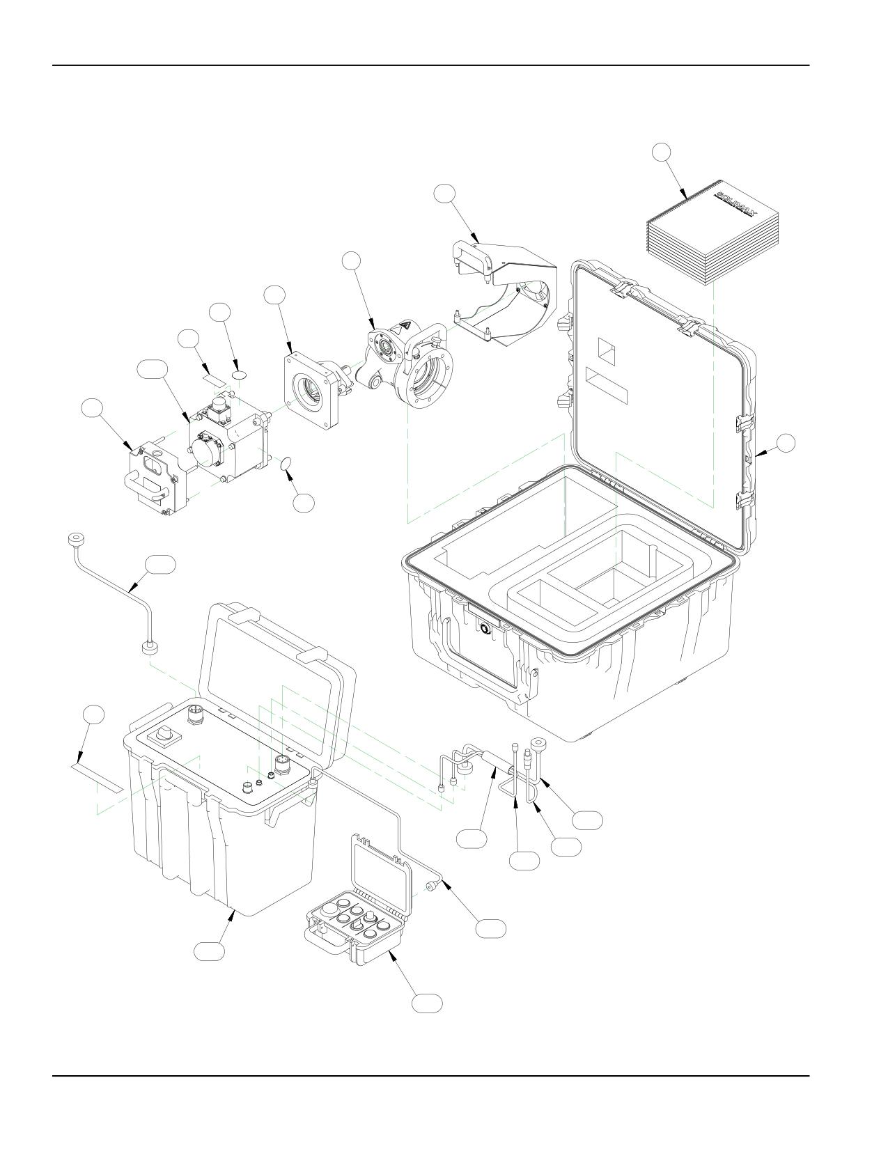
6
5.6
3
5.1
5.3
5.4
5.7.5
5.2
2
5.3
5.7.4
5.5
5.7.8
5.7.2
5.7.3
5.7.7
5.7.6
5.7.9
5.7.1
FIGURE B-21. SERVO DRIVE 230V CE ASSEMBLY (P/N 54321)
Page 106
BB4500-BB5000 Operating Manual
PARTS LIST
ITEM
QTY
P/N:
DESCRIPTION
1
1
26845
(NOT SHOWN) WRENCH HEX 3/8 SHORT ARM BONDHUS BONDHUS 10914 BALLDRIVER
2
1
52188
ASSY SHIPPING CASE WITH CUT FOAM FOR BB5000 SERVO PACKAGE
3
1
53165
RDU 12:1 BB5000 4TH GEN
4
1
55583
LAMINATED PENDANT INSTRUCTION (NOT SHOWN)
5
1
56026
SERVO DRIVE MOTOR ASSEMBLY 230V 4TH GEN
5.1
1
51536
ADAPTER BB5000 RDU TO SERVO MOTOR
5.2
1
52937
GUARD ASSY BB5000 SERVO MOTOR
5.3
2
53464
LABEL WARNING HOT HAND
5.4
1
53482
LABEL WARNING VOLTAGE
5.5
1
53483
LABEL WARNING VOLTAGE CABLE
5.6
1
56773
ASSY FAN & SHROUD BB5000 SERVO ASSY
5.7
1
96891
ASSY BB5000 SERVO DRIVE 230VAC CONTROLS MOTOR AND CABLES CE 4TH GEN
5.7.1
1
53263
PENDANT BB5000 SERVO DRIVE
5.7.2
120
56269
SLEEVE WELD COVER 1" DIA STRAIGHTLINE W/VELCRO CLOSURE (10 FT)
5.7.3
1
57016
ASSY CABLE FAN BB5000 SERVO DRIVE 242 IN LONG
5.7.4
1
66908
ASSY CORDSET BB5000 SERVO INCOMING POWER CABLE 90 DEG CONN LONG 2ND GEN
5.7.5
1
91716
SERVO MOTOR MODEL HG-SR 3.5 kW 2000 RPM 400V KEYED SHAFT
5.7.6
1
96884
CORDSET OPERATOR PENDANT BB5000 SERVO DRIVE 5M LONG 4TH GEN
5.7.7
1
96885
ASSY ENCODER CABLE BB5000 SERVO DRIVE 6 M LONG 4TH GEN
5.7.8
1
96886
ASSY CABLE BB5000 SERVO POWER CABLE 90 DEG CONN 6M LONG 4TH GEN
5.7.9
1
96890
ASSY CONTROLLER SERVO DRIVE BB5000 230/3/50-60 CE 4TH GEN
6
1
92974
MANUAL INSTRUCTION BB45000 BB5000 BORING BAR
FIGURE B-22. SERVO DRIVE 230V CE ASSEMBLY (P/N 54321)
P/N 92974, Rev. 3
Page 107
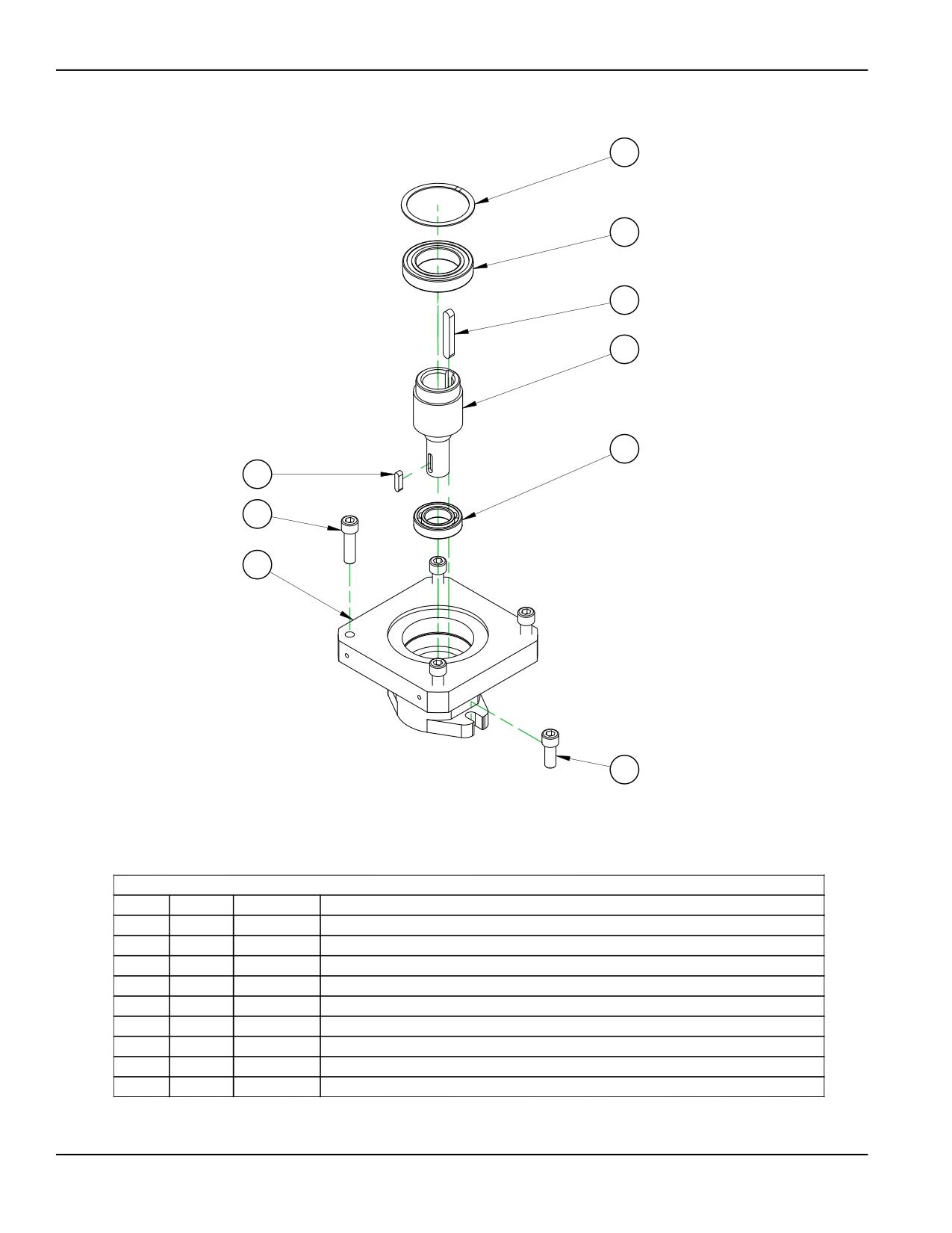
5
4
9
7
1
6
3
8
2
PARTS LIST
ITEM
QTY
PART No.
DESCRIPTION
1
1
12524
BRG BALL 1.1811 ID X 2.1654 X .50
2
2
12646
SCREW 1/2-13 X 1-1/4 SHCS
3
4
20534
SCREW 1/2-13 X 1-3/4 SHCS
4
1
22575
BRG BALL 1.9685 ID X 3.1496 OD X .6299
5
1
39131
RING SNAP 3.149 ID (80mm) SPIRAL MED DUTY
6
1
48909
KEY 1/4 X 1/4 X 1.00 RAD BOTH ENDS
7
1
51530
SHAFT BB5000 RDU TO SERVO
8
1
51531
HOUSING ADAPTER BB5000 RDU INPUT TO PLANETARY
9
1
53195
KEY 10mm x 8mm x 2.5 LONG RADIUS BOTH END
FIGURE B-23. SERVO MOTOR RDU ADAPTER ASSEMBLY (P/N 51536)
Page 108
BB4500-BB5000 Operating Manual
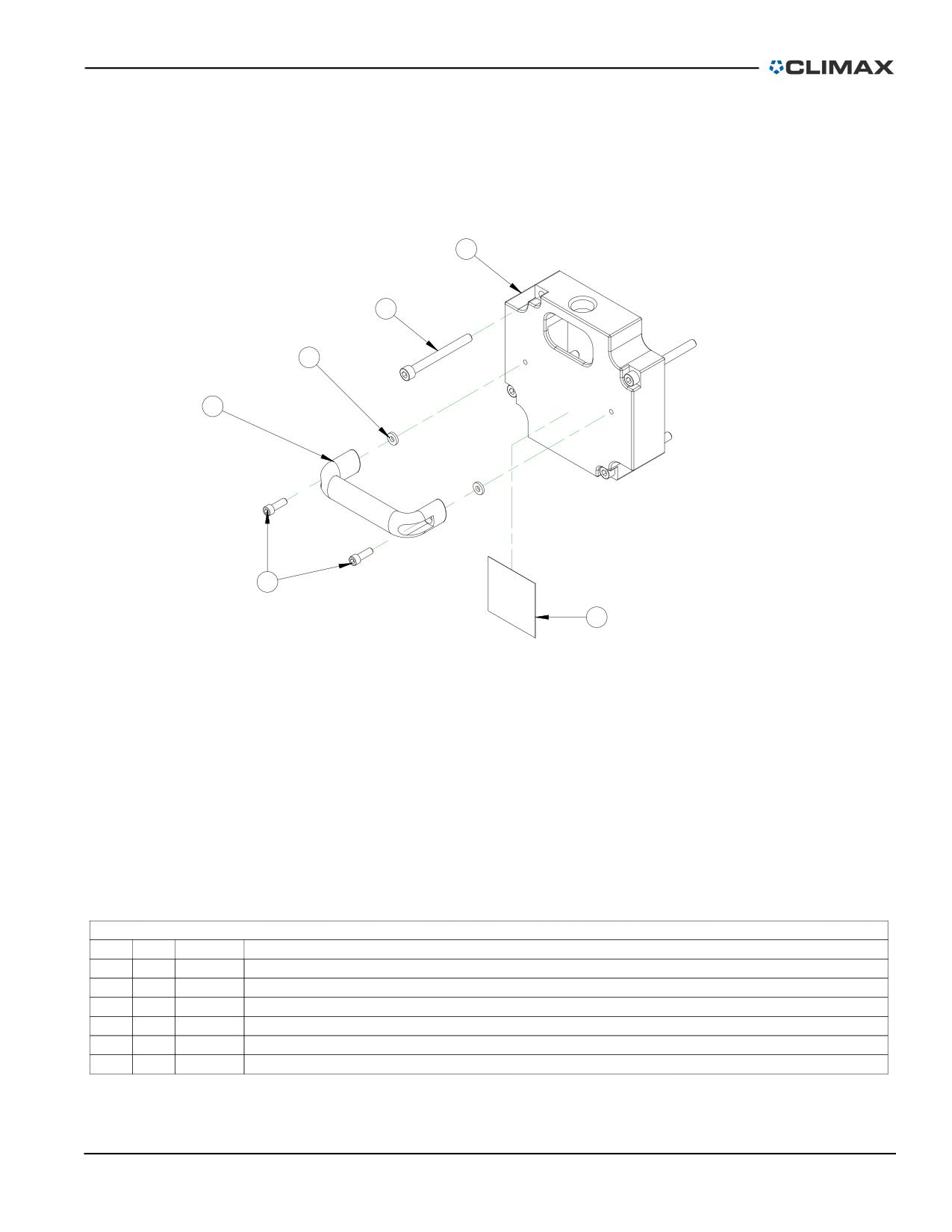
2
3
6
4
1
5
PARTS LIST
ITEM
QTY
P/N:
DESCRIPTION
1
2
10160
SCREW 1/4-20 X 3/4 SHCS
2
1
52916
GUARD SERVO MOTOR REAR PLATE
3
4
52936
SCREW M8 X 1.25 X 80MM SHCS
4
1
53462
HANDLE PULL 1/4 CBORE MTG 2.0 X 5.12 X 1.02W PLASTIC COATED
5
1
53484
LABEL "HANDLE WITH CARE"
6
2
56079
WASHER RUBBER 1/4 X 1/2 X .093
FIGURE B-24. SERVO MOTOR GUARD ASSEMBLY (P/N 52937)
P/N 92974, Rev. 3
Page 109
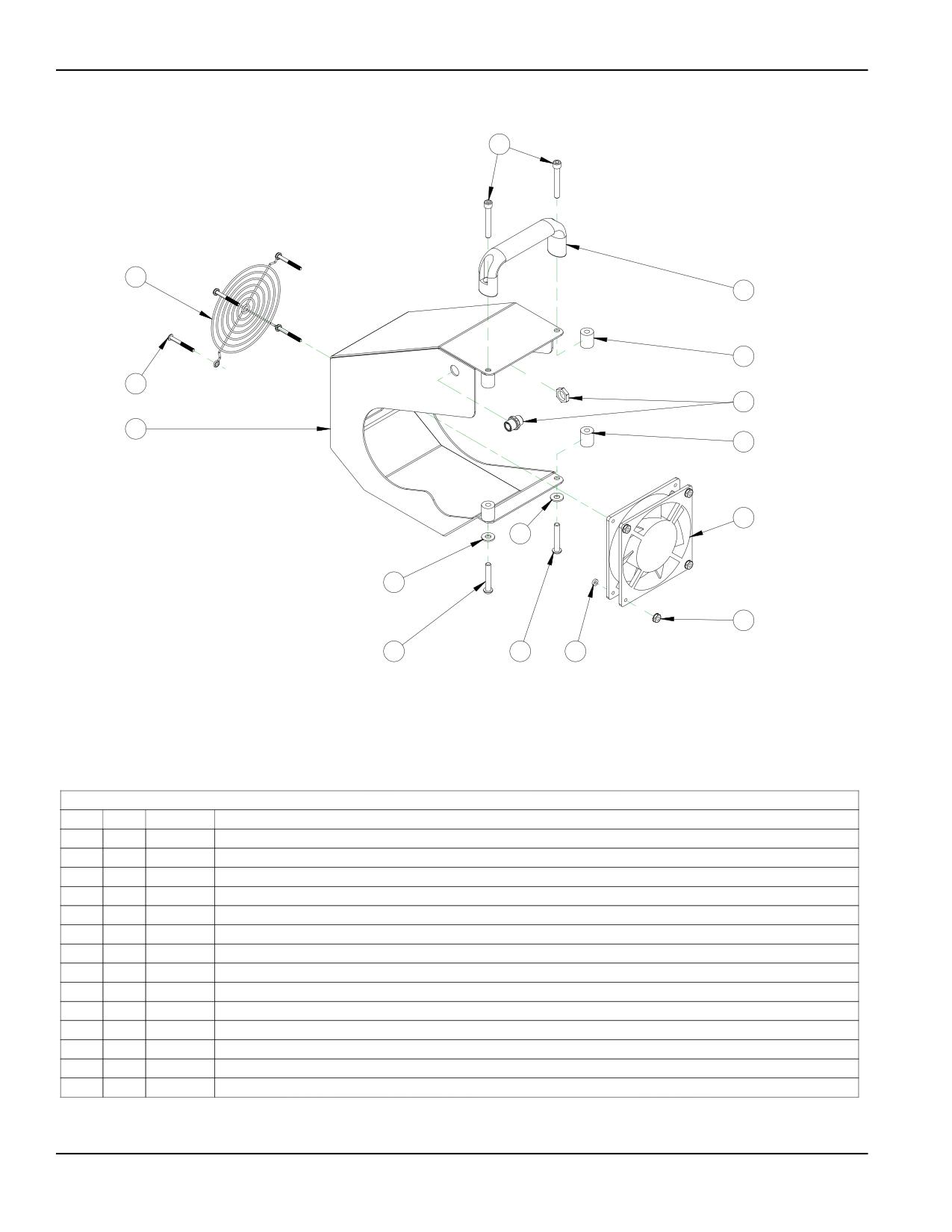
2
14
7
10
11
9
8
10
13
1
1
6
4
4
12
PARTS LIST
ITEM
QTY
P/N:
DESCRIPTION
1
2
10702
WASHER 1/4 FLTW SAE
2
2
13252
SCREW 1/4-20 X 1-3/4 SHCS
3
1
13296
(NOT SHOWN) MOUNTING BASE WIRE TIE ADHESIVE BACKED LARGE
4
2
19001
SCREW 1/4-20 X 1-1/2 BHSCS
5
2 IN
22800
(NOT SOWN) TUBE SHRINK .125 DIA BLACK
6
4
28617
NUT 8-32 LOCKING STAR WASHER
7
1
53462
HANDLE PULL 1/4 CBORE MTG 2.0 X 5.12 X 1.02W PLASTIC COATED
8
1
56587
SHROUD FAN BB5000 RDU SERVO
9
1
56757
RECEPTACLE MICROFAST 3 POLE MALE 1/4 NPT THD 0.5M LONG CONDUCTORS
10
4
56767
SPACER ROUND .252 ID X .625 OD X .75 ALUMINUM
11
4
56771
SCREW 8-32 X 1-1/2 BHSCS
12
4
56772
WASHER #8 FLTW RUBBER .93 THICK
13
1
56774
FAN 4.69" SQUARE X 1" 24 VDC 80CFM
14
1
56775
GUARD FAN STEEL WIRE 4.13" SQUARE BOLT PATTERN
FIGURE B-25. SERVO SHROUD FAN ASSEMBLY (P/N 56773)
Page 110
BB4500-BB5000 Operating Manual
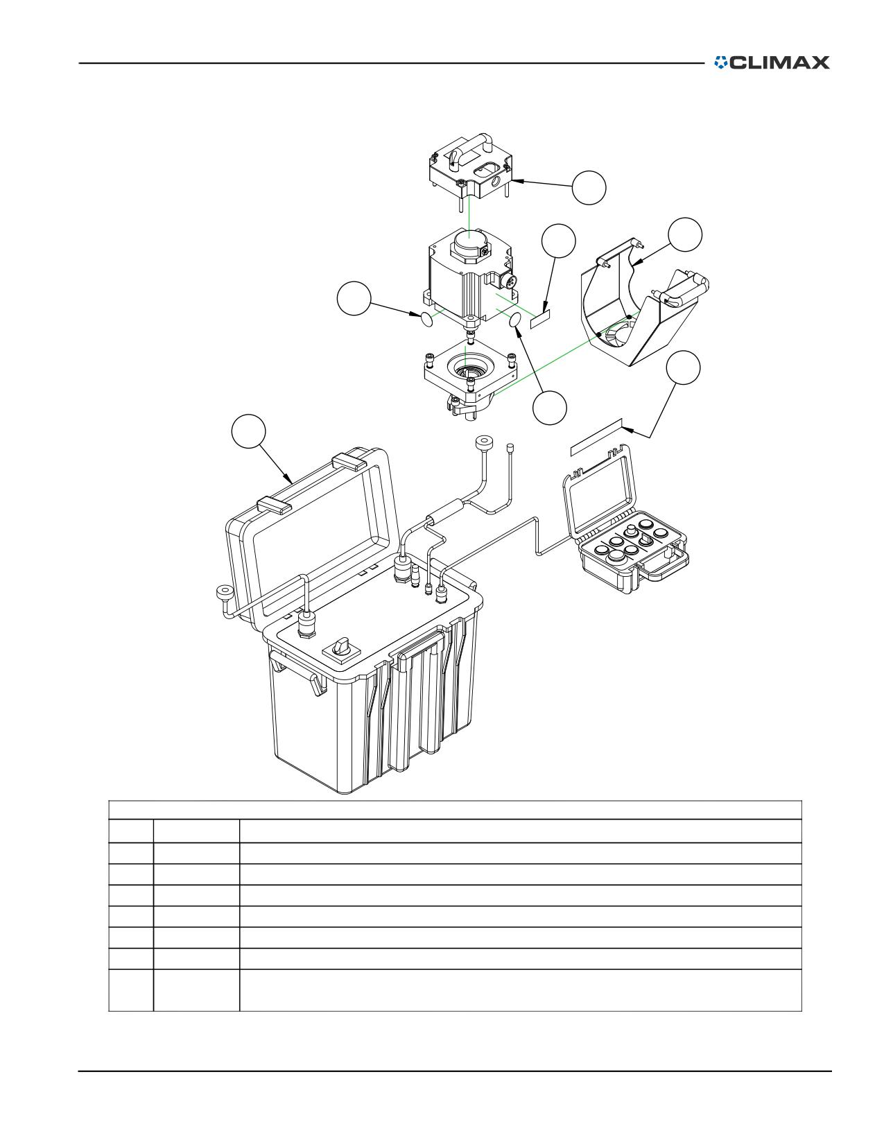
2
6
4
3
5
3
7
PARTS LIST
ITEM
PART No.
DESCRIPTION
1
51536
ADAPTER BB5000 RDU TO SERVO MOTOR
2
52937
GUARD ASSY BB5000 SERVO MOTOR
3
53464
LABEL WARNING HOT HAND
4
53482
LABEL WARNING VOLTAGE
5
53483
LABEL WARNING VOLTAGE CABLE
6
56773
SHROUD FAN BB5000 SERVO ASSY
7
71068
ASSY BB5000 SERVO DRIVE 230VAC CONTROLS MOTOR AND CABLES
NOT CE 2ND GEN
FIGURE B-26. SERVO DRIVE MOTOR 230V NON-CE ASSEMBLY (P/N 71071)
P/N 92974, Rev. 3
Page 111
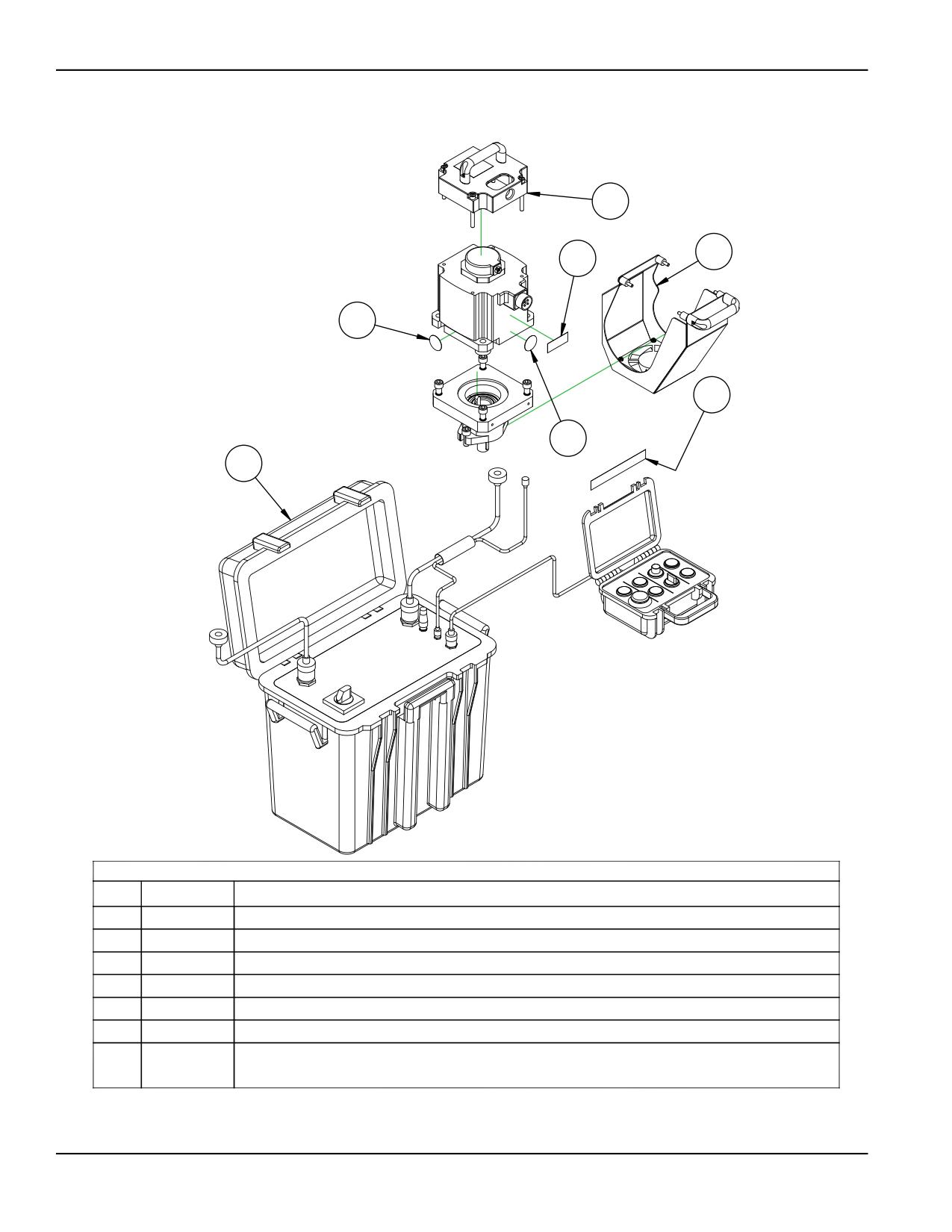
2
6
4
3
5
3
7
PARTS LIST
ITEM
PART No.
DESCRIPTION
1
51536
ADAPTER BB5000 RDU TO SERVO MOTOR
2
52937
GUARD ASSY BB5000 SERVO MOTOR
3
53464
LABEL WARNING HOT HAND
4
53482
LABEL WARNING VOLTAGE
5
53483
LABEL WARNING VOLTAGE CABLE
6
56773
SHROUD FAN BB5000 SERVO ASSY
7
71067
ASSY BB5000 SERVO DRIVE 460VAC CONTROLS MOTOR AND CABLES
NOT CE 2ND GEN
FIGURE B-27. SERVO DRIVE MOTOR 460V NON-CE ASSEMBLY (P/N 71072)
Page 112
BB4500-BB5000 Operating Manual
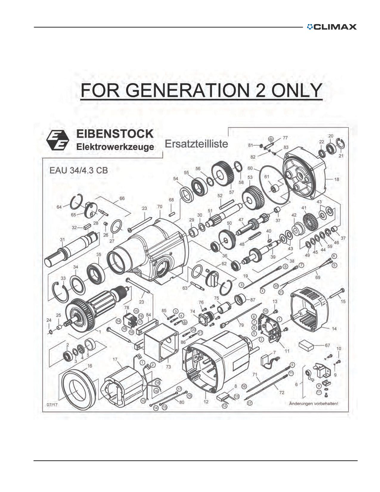
FIGURE B-28. EIBENSTOCK MOTOR ASSEMBLY -- GEN. 2 ONLY
P/N 92974, Rev. 3
Page 113
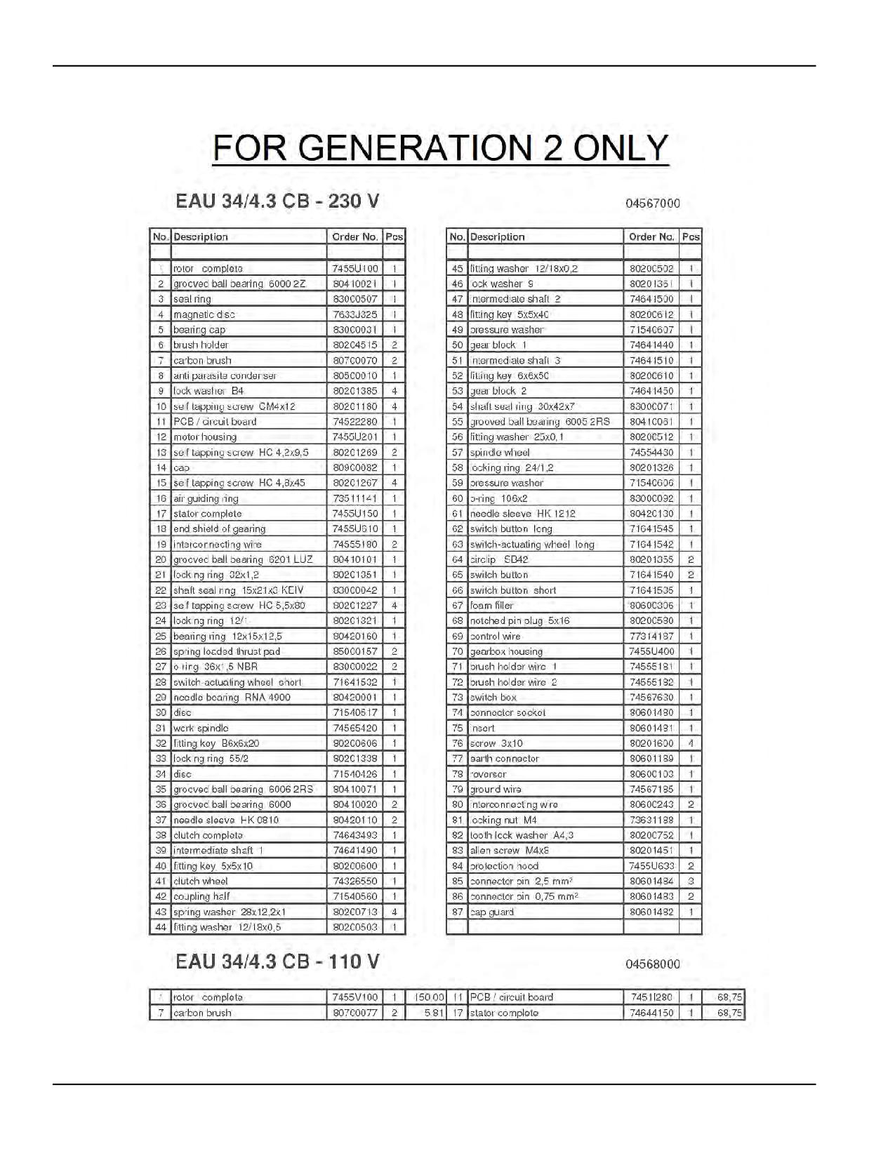
FIGURE B-29. EIBENSTOCK MOTOR ASSEMBLY PARTS LIST -- GEN. 2 ONLY
Page 114
BB4500-BB5000 Operating Manual
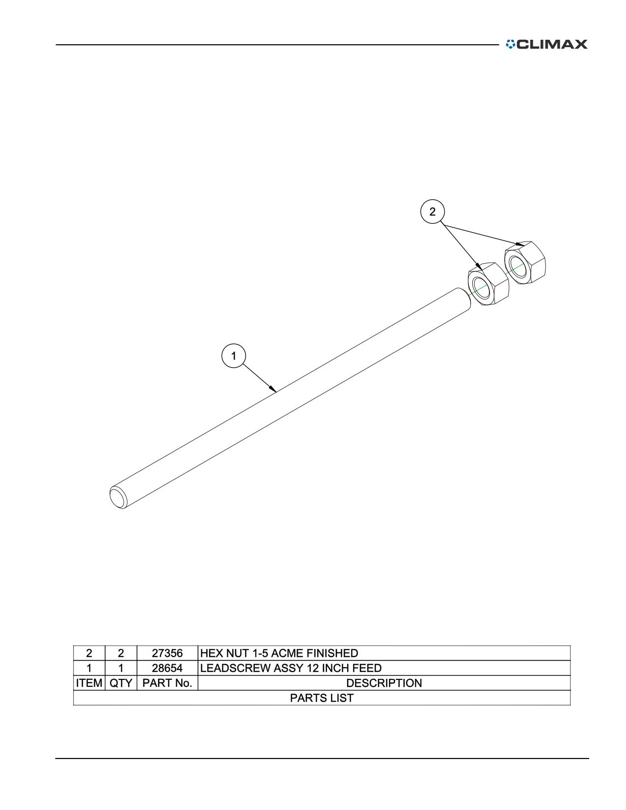
FIGURE B-30. LEADSCREW ASSEMBLY (P/N 28654)
P/N 92974, Rev. 3
Page 115

TABLE B-1. BB5000 RECOMMENDED SPARE PARTS
Part
Component
Description
Quantity
number
2 Rotational
Drive Unit & 2
12395
CLAMP COLLAR SPLIT HINGED 2-1/2 ID
4
Axial Feed-
box Assembly
25957
BRG ROLLER CLUTCH 1 ID X 1.312 OD X .625
4
26850
HANDLE CRANK MODIFIED
1
Axial Feed-
27015
PIN DOWEL MODIFIED .187 DIA X .75 GROOVED
2
box Assembly
27197
LEAD NUT BB4500 BB5000 AXIAL FEED
2
92494
SCREW ASSY FEED STOP GEN 2
2
10191
SCREW 3/8-16 X 1 SHCS
2
11691
SCREW 1/2-13 X 1-1/2 SHCS
2
Boring Head /
Bar
11734
SCREW 3/8-16 X 3/4 SSSCP
4
13356
SCREW 5/8-11 X 2-1/2 SHCS
4
20273
KEY 1/4 SQ X 1.00 SQ BOTH ENDS
1
WRENCH HEX 3/8 SHORT ARM BONDHUS BALL-
Electric Motor
26845
1
DRIVER
Assembly
SP BRUSH CARBON PAIR FOR EIBENSTOCK EAU 34/
82698
2
4.1 BB4500 BB5000
Leadscrew
27356
NUT 1-5 ACME 7/8 TALL 1-1/2 HEX FINISHED
2
Assembly
48909
KEY 1/4 SQ X 1.00 RADIUS BOTH ENDS
1
Servo Motor
Assembly
53195
KEY 10mm X 8mm X 2.05 LONG RADIUS BOTH END
1
14036
SCREW 1/2-13 X 2 SHCS
8
Spherical
21798
WASHER 5/16 FLTW HARDENED 1/8 THK BLK OX
4
Bearing
22662
WASHER 1/2 FLTW HARDENED 1-1/8 OD X 1/8 THICK
8
Mounting
Brackets
26250
SCREW 5/16-24 X 2 HHCS
4
26252
SCREW 1/2-20 X 2 SSSFP
4
Page 116
BB4500-BB5000 Operating Manual
TABLE B-2. BB4500-BB5000 SPARE PARTS KIT (P/N 97276)
Part
Description
Quantity
number
10191
SCREW 3/8-16 X 1 SHCS
2
11691
SCREW 1/2-13 X 1-1/2 SHCS
2
11734
SCREW 3/8-16 X 3/4 SSSCP
4
12395
CLAMP COLLAR SPLIT HINGED 2-1/2 ID (VMI)
4
13356
SCREW 5/8-11 X 2-1/2 SHCS
4
14036
SCREW 1/2-13 X 2 SHCS
8
20273
KEY 1/4 SQ X 1.00 SQ BOTH ENDS (KB)
1
21798
WASHER 5/16 FLTW HARDENED 1/8 THK BLK OX
3
WASHER 1/2 FLTW HARDENED 1-1/8 OD X 1/8 THICK
22662
8
BLACK OXIDE
26250
SCREW 5/16-24 X 2 HHCS
4
26252
SCREW 1/2-20 X 2 SSSFP
4
WRENCH HEX 3/8 SHORT ARM BONDHUS BONDHUS
26845
1
10914 BALLDRIVER
26850
HANDLE CRANK MODIFIED
1
27356
NUT 1-5 ACME 7/8 TALL 1-1/2 HEX FINISHED
2
KIT SERVICE BB5000 BB4500 AFU 3RD GEN COM-
38545
1
PREHENSIVE
SP BRUSH CARBON SINGLE (NOT A PAIR) FOR
82698
EIBENSTOCK EAU 34/4.1 BB4500 BB5000 120V (2
2
WIRES)
82949
BAG TOOL 14 X 5.5 X 6 POLYESTER
1
TABLE B-3. LEADSCREW SPARE PARTS
Part
Description
Quantity
number
28654
ASSY LEADSCREW 12 INCH FEED
1
28687
ASSY LEADSCREW 24 INCH FEED
1
28688
ASSY LEADSCREW 36 INCH FEED
1
P/N 92974, Rev. 3
Page 117
TABLE B-4. HYDRAULIC METRIC SPARE PARTS
Part
Description
Quantity
number
10191
SCREW 3/8-16 X 1 SHCS
2
11691
SCREW 1/2-13 X 1-1/2 SHCS
2
11734
SCREW 3/8-16 X 3/4 SSSCP
4
13356
SCREW 5/8-11 X 2-1/2 SHCS
4
14036
SCREW 1/2-13 X 2 SHCS
8
21798
WASHER 5/16 FLTW HARDENED 1/8 THK BLK OX
4
22662
WASHER 1/2 FLTW HARDENED 1-1/8 OD X 1/8 THICK
8
25957
BRG ROLLER CLUTCH 1 ID X 1.312 OD X .625
4
26250
SCREW 5/16-24 X 2 HHCS
4
26252
SCREW 1/2-20 X 2 SSSFP
4
26850
HANDLE CRANK MODIFIED
1
27015
SP PIN DOWEL MODIFIED .187 DIA X .75 GROOVED
2
27197
LEAD NUT BB4500 BB5000 AXIAL FEED
2
92494
SCREW ASSY FEED STOP GEN 2
2
27356
NUT 1-5 ACME 7/8 TALL 1-1/2 HEX FINISHED
2
29207
SPRING PLUNGER HAND RETRACT 1/2 X 13
2
33999
WRENCH HEX SET .050 - 3/8 BONDHUS BALL END
1
34571
BIT TOOL HSS 12MM X 4.0 LH FINISH SINGLE TC
4
34572
BIT TOOL HSS 12MM X 2.5 LH FINISH SINGLE TC
4
34573
BIT TOOL HSS 12MM X 1.8 LH FINISH SINGLE TC
4
34576
BIT TOOL HSS 12MM X 4.0 LH ROUGHING SINGLE
4
34577
BIT TOOL HSS 12MM X 2.5 LH ROUGHING SINGLE
4
34578
BIT TOOL HSS 12MM X 1.8 LH ROUGHING SINGLE
4
34642
SCREW M16 X 1.5 X 8 SSSFP
24
38678
WRENCH HEX SET 1.5 - 10MM BONDHUS BALL END
1
53670
ELEMENT FILTER 5/10HP HPU 10 MICRON
1
63533
TOOL HOLDER SET 12MM
2
63543
INSERT 80 DEG DIAMOND 3/8 IC .015 R KC-5010
24
64446
OIL HYDRAULIC 5 GALLON 76 UNAX AW 32
2
Page 118
BB4500-BB5000 Operating Manual
TABLE B-5. BB5000 TOOL KIT IN INCHES (P/N 28784)
Part
Description
Quantity
number
14251
WRENCH TEE 3/16 HEX (KB)
1
14650
WRENCH END 1/2 COMBINATION LONG
1
16794
WRENCH HEX BIT 3/8 DRIVER X 1/2 DRIVE
1
25550
WRENCH HEX 5/16 X 11.4 BALLDRIVER T-HANDLE
1
29041
WRENCH END 1-1/2 THIN (SINGLE OPEN END)
1
29199
WRENCH HEX 1/2 LONG ARM
1
29660
WRENCH HEX BIT 5/16 DRIVER X 12 DRIVE
1
29661
WRENCH HINGE HANDLE 1/2 DRIVE 17 IN HANDLE
1
31857
BIT TOOL HSS 1/2 X 1.0 LH FINISHING SINGLE
1
31858
BIT TOOL HSS 1/2 X 1.8 LH FINISHING SINGLE TC
1
31866
BIT TOOL HSS 1/2 X 1.0 LH ROUGHING SINGLE
1
31867
BIT TOOL HSS 1/2 X 1.8 LH ROUGHING SINGLE
1
32342
BIT TOOL HSS 1/2 X 2.5 LH FINISHING SINGLE TC
1
32344
BIT TOOL HSS 1/2 X 2.5 LH ROUGHING SINGLE
1
33785
WRENCH TORX T-45 (KB)
1
33999
WRENCH HEX SET .050 - 3/8 BONDHUS BALL END
1
55923
WRENCH TEE 1/4 HEX
1
55924
WRENCH TEE 3/8 HEX
1
60880
HAMMER DEAD BLOW 42OZ
1
82949
BAG TOOL 14 X 5.5 X 6 POLYESTER
1
92974
MANUAL INSTRUCTION BB4500 BB5000 BORING BAR
1
TABLE B-6. BB5000 TOOL KIT IN METRIC (P/N 34580)
Part
Description
Quantity
number
13052
WRENCH HEX BIT SOCKET 1/2 X 1/2
1
14251
WRENCH TEE 3/16 HEX
1
14650
WRENCH END 1/2 COMBINATION LONG
1
16794
WRENCH HEX BIT 3/8 DRIVER X 1/2 DRIVE
1
25550
WRENCH HEX 5/16 X 11.4 BALLDRIVER T-HANDLE
1
P/N 92974, Rev. 3
Page 119
TABLE B-6. BB5000 TOOL KIT (CONTINUED)IN METRIC (P/N 34580)
Part
Description
Quantity
number
29041
WRENCH END 1-1/2 (SINGLE OPEN END)
1
29199
WRENCH HEX 1/2 LONG ARM
1
29652
WRENCH HEX 3MM SHORT ARM
1
29660
WRENCH HEX BIT 5/16 DRIVER X 12 DRIVE
1
29661
WRENCH HINGE HANDLE 1/2 DRIVE 17 IN HANDLE
1
33785
WRENCH TORX T-45
1
33999
WRENCH HEX SET .050 - 3/8 BONDHUS BALL END
1
34568
WRENCH HEX 5MM SHORT ARM
1
34572
BIT TOOL HSS 12MM X 2.5 LH FINISH SINGLE TC
1
34573
BIT TOOL HSS 12MM X 1.8 LH FINISH SINGLE TC
1
34574
BIT TOOL HSS 12MM X 1.0 LH FINISH SINGLE TC
1
34577
BIT TOOL HSS 12MM X 2.5 LH ROUGHING SINGLE
1
34578
BIT TOOL HSS 12MM X 1.8 LH ROUGHING SINGLE
1
34579
BIT TOOL HSS 12MM X 1.0 LH ROUGHING SINGLE
1
35340
WRENCH HEX 8MM SHORT ARM
1
35516
HAMMER DEAD BLOW 1-3/4 DIA HEAD
1
55923
WRENCH TEE 1/4 HEX
1
55924
WRENCH 3/8 HEX T-HANDLE
1
82949
BAG TOOL 14 X 5.5 X 6 POLYESTER
1
MANUAL INSTRUCTION BB4500 BB5000 BORING
92974
1
BAR
Page 120
BB4500-BB5000 Operating Manual
APPENDIX C SCHEMATICS
Schematic list
FIGURE C-1. BB4500-BB5000 EIBENSTOCK CONTROLLER 2ND GEN 230V 50-60 HZ CE SCHEMATIC (P/N 88035 C00467)
122
FIGURE C-2. BB4500-BB5000 EIBENSTOCK CONTROLLER 2ND GEN 230V 50-60 HZ DOMESTIC ASSEMBLY (P/N 88036 C00468)
123
FIGURE C-3. BB4500-BB5000 EIBENSTOCK CONTROLLER 2ND GEN 120V DOMESTIC ASSEMBLY (P/N 88037 C00465) 124
FIGURE C-4. BB4500-BB5000 EIBENSTOCK CONTROLLER 2ND GEN 120V CE ASSEMBLY (P/N 88038 C00466) - - - 125
FIGURE C-5. BB5000 MOTOR 230V AND 460V FAN ASSEMBLY (P/N 91811 E00034) - - - - - - - - - - - - - - - 126
FIGURE C-6. BB5000 SERVO MOTOR 230VAC AND 460VAC POWER CABLE ASSEMBLY (P/N 91811 E00048) - - - - 127
FIGURE C-7. BB5000 EIBENSTOCK MOTOR CABLE ASSEMBLY 2ND GEN 120V 12AWG SCHEMATIC (P/N 88649 E00170) 128
FIGURE C-8. BB5000 EIBENSTOCK MOTOR CABLE ASSEMBLY 2ND GEN 230V 14AWG SCHEMATIC (P/N 88650 E00171) 129
FIGURE C-9. BB5000 EIBENSTOCK POWER CABLE ASSEMBLY 2ND GEN 120V DOMESTIC L5-30P PLUG (P/N 88652 E00172)
130
FIGURE C-10. BB5000 EIBENSTOCK POWER CABLE ASSEMBLY 2ND GEN 120V CE 332P4W PIN/SLEEVE PLUG (P/N 88653
E00173) - - - - - - - - - - - - - - - - - - - - - - - - - - - - - - - - - - - - - - - - - - - - - - - - - - - 131
FIGURE C-11. BB5000 EIBENSTOCK POWER CABLE ASSEMBLY 2ND GEN 230V CE CEE7/7 SCHUKO PLUG (P/N 88654 E00174)
132
FIGURE C-12. BB5000 EIBENSTOCK POWER CABLE ASSEMBLY 2ND GEN 230V DOMESTIC L6-15P PLUG (P/N 88655 E00175)
133
FIGURE C-13. PNEUMATIC CONDITIONING UNIT SCHEMATIC (P/N 59248)
- - - - - - - - - - - - - - - - - - - - - 134
FIGURE C-14. BB4500-BB5000 EIBENSTOCK CONTROLLER 2ND GEN 230V 50-60 HZ CE ASSEMBLY (P/N 88035 B00367)
135
FIGURE C-15. BB4500-BB5000 EIBENSTOCK CONTROLLER 2ND GEN 230V 50-60 HZ DOMESTIC ASSEMBLY (P/N 88036
B00368) - - - - - - - - - - - - - - - - - - - - - - - - - - - - - - - - - - - - - - - - - - - - - - - - - - - 136
FIGURE C-16. BB4500-BB5000 EIBENSTOCK CONTROLLER 2ND GEN 120V DOMESTIC ASSEMBLY (P/N 88037 B00365) 137
FIGURE C-17. BB4500-BB5000 EIBENSTOCK CONTROLLER 2ND GEN 120V CE ASSEMBLY (P/N 88038 B00366) - - 138
FIGURE C-18. BB5000 SERVO CONTROLLER 3RD GEN 460VAC CE ASSEMBLY (P/N A00099) - - - - - - - - - - - 139
FIGURE C-19. BB5000 EIBENSTOCK CONTROLLER 2ND GEN 120V DOMESTIC ASSEMBLY (P/N A00100) - - - - - - - 140
FIGURE C-20. BB5000 SERVO PENDANT ASSEMBLY (P/N B00024) - - - - - - - - - - - - - - - - - - - - - - - - 141
P/N 92974, Rev. 3
Page 121