Caterpillar. 3406C Industrial Engines. Operation and Maintenance Manual (2000)
UUTi
CATERPILLAR ENGINE
OPERATION and MAINTENANCE
MANUAL
This manual contains important safety information.
Do not destroy this manual.
This manual must be available to the personnel who operate and maintain this machine.
Reproduced by IR with permission.
P.O. Box 868
501 Sanford Ave
Mocksville, N.C. 27028
Manual 22464952 (11-06)
SEBU6993-02
June 2000
Operation and
Maintenance
Manual
3406C Industrial Engines
3ER1-Up (Engine)
This Manual Must be Accessible at the Point of Operation
i01097883
Important Safety Information
Most accidents that involve product operation, maintenance and repair are caused by failure to
observe basic safety rules or precautions. An accident can often be avoided by recognizing potentially
hazardous situations before an accident occurs. A person must be alert to potential hazards. This
person should also have the necessary training, skills and tools to perform these functions properly.
Improper operation, lubrication, maintenance or repair of this product can be dangerous and
could result in injury or death.
Do not operate or perform any lubrication, maintenance or repair on this product, until you have
read and understood the operation, lubrication, maintenance and repair information.
Safety precautions and warnings are provided in this manual and on the product. If these hazard
warnings are not heeded, bodily injury or death could occur to you or to other persons.
The hazards are identified by the “Safety Alert Symbol” and followed by a “Signal Word” such as
“DANGER”, “WARNING” or “CAUTION”. The Safety Alert “WARNING” label is shown below.
The meaning of this safety alert symbol is as follows:
Attention! Become Alert! Your Safety is Involved.
The message that appears under the warning explains the hazard and can be either written or
pictorially presented.
Operations that may cause product damage are identified by “NOTICE” labels on the product and in
this publication.
Caterpillar cannot anticipate every possible circumstance that might involve a potential hazard. The
warnings in this publication and on the product are, therefore, not all inclusive. If a tool, procedure,
work method or operating technique that is not specifically recommended by Caterpillar is used,
you must satisfy yourself that it is safe for you and for others. You should also ensure that the
product will not be damaged or be made unsafe by the operation, lubrication, maintenance or
repair procedures that you choose.
The information, specifications, and illustrations in this publication are on the basis of information that
was available at the time that the publication was written. The specifications, torques, pressures,
measurements, adjustments, illustrations, and other items can change at any time. These changes can
affect the service that is given to the product. Obtain the complete and most current information before
you start any job. Caterpillar dealers have the most current information available. For a list of the most
current publication form numbers available, see the Service Manual Contents Microfiche, REG1139F.
When replacement parts are required for this
product Caterpillar recommends using Caterpil-
lar replacement parts or parts with equivalent
specifications including, but not limited to, phys-
ical dimensions, type, strength and material.
Failure to heed this warning can lead to prema-
ture failures, product damage, personal injury or
death.
3
Table of Contents
Reference Information Section
Table of Contents
Customer Service
90
Foreword
4
Reference Materials
92
Safety Section
Index Section
Safety Signs and Labels
6
Index
96
General Hazard Information
7
Burn Prevention
10
Fire Prevention and Explosion Prevention
10
Crushing Prevention and Cutting Prevention
12
Mounting and Dismounting
12
Before Starting Engine
12
Engine Starting
13
Engine Stopping
13
Product Information Section
Model Views
14
Product Identification Information
17
Operation Section
Engine Lifting and Storage
19
Gauges and Indicators
20
Engine Features and Controls
21
Engine Starting
24
Engine Operation
28
Engine Stopping
30
Cold Weather Operation
32
Maintenance Section
Torque Specifications
34
Lubricant Specifications
37
Fuel Specifications
44
Cooling System Specifications
46
Refill Capacities
58
Maintenance Interval Schedule
59
4
Foreword
Foreword
Use fuel consumption or service hours to determine
intervals. Calendar intervals shown (daily, annually,
etc.) may be used instead of service meter intervals
Literature Information
if they provide more convenient schedules and
approximate the indicated service meter reading.
This manual contains safety, operation instructions,
lubrication and maintenance information. This
Recommended service should be performed
manual should be stored in or near the engine area
at the appropriate intervals as indicated in
in a literature holder or literature storage area. Read,
the Maintenance Interval Schedule. The actual
study and keep it with the literature and engine
operating environment of the engine also governs
information.
the Maintenance Interval Schedule. Therefore,
under extremely severe, dusty, wet or freezing cold
English is the primary language for all Caterpillar
operating conditions, more frequent lubrication and
publications. The English used facilitates translation
maintenance than is specified in the Maintenance
and consistency in electronic media delivery.
Interval Schedule may be necessary.
Some photographs or illustrations in this manual
The maintenance schedule items are organized
show details or attachments that may be different
for a preventive maintenance management
from your engine. Guards and covers may have
program. If the preventive maintenance program
been removed for illustrative purposes. Continuing
is followed, a periodic tune-up is not required.
improvement and advancement of product design
The implementation of a preventive maintenance
may have caused changes to your engine which are
management program should minimize operating
not included in this manual. Whenever a question
costs through cost avoidances resulting from
arises regarding your engine, or this manual, please
reductions in unscheduled downtime and failures.
consult with your Caterpillar dealer for the latest
available information.
Maintenance Intervals
Safety
Perform maintenance on items at multiples
of the original requirement. Each level and/or
This safety section lists basic safety precautions.
individual items in each level should be shifted
In addition, this section identifies hazardous,
ahead or back depending upon your specific
warning situations. Read and understand the basic
maintenance practices, operation and application.
precautions listed in the safety section before
We recommend that the maintenance schedules
operating or performing lubrication, maintenance
be reproduced and displayed near the engine as
and repair on this product.
a convenient reminder. We also recommend that a
maintenance record be maintained as part of the
Operation
engine’s permanent record.
Operating techniques outlined in this manual are
See the section in the Operation and Maintenance
basic. They assist with developing the skills and
Manual, “Maintenance Records” for information
techniques required to operate the engine more
regarding documents that are generally accepted
efficiently and economically. Skill and techniques
as proof of maintenance or repair. Your authorized
develop as the operator gains knowledge of the
Caterpillar dealer can assist you in adjusting your
engine and its capabilities.
maintenance schedule to meet the needs of your
operating environment.
The operation section is a reference for operators.
Photographs and illustrations guide the operator
Overhaul
through procedures of inspecting, starting,
operating and stopping the engine. This section
Major engine overhaul details are not covered in the
also includes a discussion of electronic diagnostic
Operation and Maintenance Manual except for the
information.
interval and the maintenance items in that interval.
Major repairs are best left to trained personnel or
Maintenance
an authorized Caterpillar dealer. Your Caterpillar
dealer offers a variety of options regarding overhaul
The maintenance section is a guide to engine
programs. If you experience a major engine failure,
care. The illustrated, step-by-step instructions are
there are also numerous after failure overhaul
grouped by fuel consumption, service hours and/or
options available from your Caterpillar dealer.
calendar time maintenance intervals. Items in the
Consult with your dealer for information regarding
maintenance schedule are referenced to detailed
these options.
instructions that follow.
5
Foreword
California Proposition 65 Warning
Diesel engine exhaust and some of its constituents
are known to the State of California to cause cancer,
birth defects, and other reproductive harm.
Battery posts, terminals and related accessories
contain lead and lead compounds. Wash hands
after handling.
6
Safety Section
Safety Signs and Labels
Battery
Safety Section
i01368857
Safety Signs and Labels
SMCS Code: 1000; 7405
There may be several specific safety signs on an
g00524010
Illustration 1
engine. The exact location of the hazards and the
Typical location of the batteries in the battery compartment
description of the hazards are reviewed in this
section. Please become familiar with all safety signs.
The warning label for the battery is installed on the
side of the engine or in a visible location near the
Ensure that all of the safety signs are legible. Clean
battery. If batteries are located on both sides of the
the safety signs or replace the safety signs if the
package, the warning label is located on both sides
words cannot be read or if the pictures are not
of the package.
visible. When the safety signs are cleaned, use a
cloth, water, and soap. Do not use solvent, gasoline,
or other harsh chemicals to clean the safety signs.
Solvents, gasoline, or harsh chemicals could loosen
the adhesive that secures the safety signs. The
safety signs that are loosened could drop off of
the engine.
Replace any damaged safety signs or missing
safety signs. If a safety sign is attached to a part of
the engine that is replaced, install a new safety sign
on the replacement part. Any Caterpillar dealer can
provide new safety signs.
g00455028
Do not operate or work on this engine unless you
have read and understand the instructions and
warnings in the Operation and Maintenance Man-
ual. Failure to follow the instructions or heed the
Improper jumper cable connections can cause an
warnings could result in injury or death. Contact
explosion resulting in personal injury.
any Caterpillar dealer for replacement manuals.
Proper care is your responsibility.
Batteries may be located in separate compartments.
When you are using jump start cables, always
The safety signs that may be found on the engine
connect the positive “+” cable to the positive “+”
are illustrated and described below.
terminal of the battery that is connected to the
starting motor solenoid. Connect the negative “-”
cable from the external source to the negative “-”
terminal of the starting motor. If the starting motor
does not have a negative “-” terminal, connect the
negative “-” cable from the external source to the
engine block. Follow the procedure in this Operation
and Maintenance Manual, “Engine Starting” topic
(Operation Section).
7
Safety Section
General Hazard Information
Clutch
Engine Lifting
g00367054
Illustration 3
The warning label for lifting the engine with a fuel
tank is located on the fuel tank (if equipped).
g00107406
Illustration 2
The warning label for the clutch is located on the
clutch housing (if equipped).
g00524148
Lift eyes or tank can fail when lifting tank con-
taining fluids resulting in possible personal injury.
g00107407
Drain tank of all fluids before lifting.
Rotating gears can cause finger entanglement or
hand entanglement. Do not service this component
i01359759
without first reading the operator manual.
General Hazard Information
SMCS Code: 1000; 7405
g00104545
Illustration 4
8
Safety Section
General Hazard Information
Attach a “Do Not Operate” warning tag or a similar
• Do not wear loose clothing or jewelry that can
warning tag to the start switch or to the controls
snag on controls or on other parts of the engine.
before the engine is serviced or before the engine
is repaired. These warning tags (Special Instruction,
• Ensure that all protective guards and all covers
SEHS7332) are available from your Caterpillar
are secured in place on the engine.
dealer. Attach the warning tags to the engine
and to each operator control station. When it is
• Never put maintenance fluids into glass
appropriate, disconnect the starting controls.
containers. Glass containers can break.
Do not allow unauthorized personnel on the engine,
• Use all cleaning solutions with care.
or around the engine when the engine is being
serviced.
• Report all necessary repairs.
Engine exhaust contains products of combustion
Unless other instructions are provided, perform
which may be harmful to your health. Always
the maintenance under the following conditions:
start the engine and operate the engine in a well
ventilated area. If the engine is in an enclosed area,
• The engine is stopped. Ensure that the engine
vent the engine exhaust to the outside.
cannot be started.
Cautiously remove the following parts. To help
• Disconnect the batteries when maintenance
prevent spraying or splashing of pressurized fluids,
is performed or when the electrical system is
hold a rag over the part that is being removed.
serviced. Disconnect the battery ground leads.
Tape the leads in order to help prevent sparks.
• Filler caps
•
Do not attempt any repairs that are not
• Grease fittings
understood. Use the proper tools. Replace
any equipment that is damaged or repair the
• Pressure taps
equipment.
• Breathers
California Proposition 65 Warning
• Drain plugs
Some engine exhaust constituents are known to the
State of California to cause cancer, birth defects,
Use caution when cover plates are removed.
and other reproductive harm.
Gradually loosen, but do not remove the last two
bolts or nuts that are located at opposite ends of
Pressure Air and Water
the cover plate or the device. Before removing the
last two bolts or nuts, pry the cover loose in order
Pressurized air and/or water can cause debris
to relieve any spring pressure or other pressure.
and/or hot water to be blown out. This could result
in personal injury.
When pressure air and/or pressure water is used
for cleaning, wear protective clothing, protective
shoes, and eye protection. Eye protection includes
goggles or a protective face shield.
The maximum air pressure for cleaning purposes
must be below 205 kPa (30 psi). The maximum
water pressure for cleaning purposes must be
below 275 kPa (40 psi).
g00702020
Illustration 5
• Wear a hard hat, protective glasses, and other
protective equipment, as required.
• When work is performed around an engine that
is operating, wear protective devices for ears in
order to help prevent damage to hearing.
9
Safety Section
General Hazard Information
Fluid Penetration
Asbestos Information
g00687600
g00702022
Illustration 6
Illustration 7
Always use a board or cardboard when you check
Caterpillar equipment and replacement parts that
for a leak. Leaking fluid that is under pressure can
are shipped from Caterpillar are asbestos free.
penetrate body tissue. Fluid penetration can cause
Caterpillar recommends the use of only genuine
serious injury and possible death. A pin hole leak
Caterpillar replacement parts. Use the following
can cause severe injury. If fluid is injected into your
guidelines when you handle any replacement parts
skin, you must get treatment immediately. Seek
that contain asbestos or when you handle asbestos
treatment from a doctor that is familiar with this type
debris.
of injury.
Use caution. Avoid inhaling dust that might be
generated when you handle components that
Containing Fluid Spillage
contain asbestos fibers. Inhaling this dust can
be hazardous to your health. The components
Care must be taken in order to ensure that fluids
that may contain asbestos fibers are brake pads,
are contained during performance of inspection,
brake bands, lining material, clutch plates, and
maintenance, testing, adjusting and repair of the
some gaskets. The asbestos that is used in these
engine. Prepare to collect the fluid with suitable
components is usually bound in a resin or sealed in
containers before opening any compartment or
some way. Normal handling is not hazardous unless
disassembling any component containing fluids.
airborne dust that contains asbestos is generated.
Refer to Special Publication, NENG2500, “Tools and
If dust that may contain asbestos is present, there
Shop Products Guide” for the following items:
are several guidelines that should be followed:
• Tools that are suitable for collecting fluids and
• Never use compressed air for cleaning.
equipment that is suitable for collecting fluids
• Avoid brushing materials that contain asbestos.
• Tools that are suitable for containing fluids and
equipment that is suitable for containing fluids
• Avoid grinding materials that contain asbestos.
Obey all local regulations for the disposal of liquids.
• Use a wet method in order to clean up asbestos
materials.
• A vacuum cleaner that is equipped with a high
efficiency particulate air filter (HEPA) can also be
used.
• Use exhaust ventilation on permanent machining
jobs.
• Wear an approved respirator if there is no other
way to control the dust.
10
Safety Section
Burn Prevention
• Comply with applicable rules and regulations
Any contact with hot coolant or with steam
for the work place. In the United States, use
can cause severe burns. Allow cooling system
Occupational Safety and Health Administration
components to cool before the cooling system is
(OSHA) requirements. These OSHA requirements
drained.
can be found in “29 CFR 1910.1001”.
Check the coolant level only after the engine has
• Obey environmental regulations for the disposal
been stopped.
of asbestos.
Ensure that the filler cap is cool before removing
• Stay away from areas that might have asbestos
the filler cap. The filler cap must be cool enough
particles in the air.
to touch with a bare hand. Remove the filler cap
slowly in order to relieve pressure.
Dispose of Waste Properly
Cooling system conditioner contains alkali. Alkali
can cause personal injury. Do not allow alkali to
contact the skin, the eyes, or the mouth.
Oils
Hot oil and hot components can cause personal
injury. Do not allow hot oil to contact the skin. Also,
do not allow hot components to contact the skin.
Batteries
Electrolyte is an acid. Electrolyte can cause
personal injury. Do not allow electrolyte to contact
g00706404
the skin or the eyes. Always wear protective glasses
Illustration 8
for servicing batteries. Wash hands after touching
the batteries and connectors. Use of gloves is
Improperly disposing of waste can threaten the
recommended.
environment. Potentially harmful fluids should be
disposed of according to local regulations.
i01359892
Always use leakproof containers when you drain
fluids. Do not pour waste onto the ground, down a
Fire Prevention and Explosion
drain, or into any source of water.
Prevention
SMCS Code: 1000; 7405
i01329129
Burn Prevention
SMCS Code: 1000; 7405
Do not touch any part of an operating engine.
Allow the engine to cool before any maintenance
is performed on the engine. Relieve all pressure
in the air system, in the hydraulic system, in the
lubrication system, in the fuel system, or in the
cooling system before any lines, fittings or related
items are disconnected.
Coolant
g00704000
Illustration 9
When the engine is at operating temperature, the
engine coolant is hot. The coolant is also under
All fuels, most lubricants, and some coolant mixtures
pressure. The radiator and all lines to the heaters or
are flammable.
to the engine contain hot coolant.
11
Safety Section
Fire Prevention and Explosion Prevention
Flammable fluids that are leaking or spilled onto hot
Inspect all lines and hoses for wear or for
surfaces or onto electrical components can cause
deterioration. The hoses must be properly routed.
a fire. Fire may cause personal injury and property
The lines and hoses must have adequate support
damage.
and secure clamps. Tighten all connections to the
recommended torque. Leaks can cause fires.
A flash fire may result if the covers for the engine
crankcase are removed within fifteen minutes after
Oil filters and fuel filters must be properly installed.
an emergency shutdown.
The filter housings must be tightened to the proper
torque.
Determine whether the engine will be operated in
an environment that allows combustible gases to be
drawn into the air inlet system. These gases could
cause the engine to overspeed. Personal injury ,
property damage, or engine damage could result.
If the application involves the presence of
combustible gases, consult your Caterpillar dealer
for additional information about suitable protection
devices.
Remove all flammable materials such as fuel, oil,
and debris from the engine. Do not allow any
flammable materials to accumulate on the engine.
Store fuels and lubricants in properly marked
containers away from unauthorized persons. Store
oily rags and any flammable materials in protective
containers. Do not smoke in areas that are used for
storing flammable materials.
Do not expose the engine to any flame.
g00704059
Illustration 10
Exhaust shields (if equipped) protect hot exhaust
Use caution when you are refueling an engine. Do
components from oil or fuel spray in case of a line,
not smoke while you are refueling an engine. Do
a tube, or a seal failure. Exhaust shields must be
not refuel an engine near open flames or sparks.
installed correctly.
Always stop the engine before refueling.
Do not weld on lines or tanks that contain flammable
fluids. Do not flame cut lines or tanks that contain
flammable fluid. Clean any such lines or tanks
thoroughly with a nonflammable solvent prior to
welding or flame cutting.
Wiring must be kept in good condition. All electrical
wires must be properly routed and securely
attached. Check all electrical wires daily. Repair any
wires that are loose or frayed before you operate
the engine. Clean all electrical connections and
tighten all electrical connections.
Eliminate all wiring that is unattached or
unnecessary. Do not use any wires or cables that
are smaller than the recommended gauge. Do not
bypass any fuses and/or circuit breakers.
Arcing or sparking could cause a fire. Secure
connections, recommended wiring, and properly
maintained battery cables will help to prevent arcing
g00704135
or sparking.
Illustration 11
12
Safety Section
Crushing Prevention and Cutting Prevention
Gases from a battery can explode. Keep any open
Unless other maintenance instructions are provided,
flames or sparks away from the top of a battery. Do
never attempt adjustments while the engine is
not smoke in battery charging areas.
running.
Never check the battery charge by placing a metal
Stay clear of all rotating parts and of all moving
object across the terminal posts. Use a voltmeter or
parts. Leave the guards in place until maintenance
a hydrometer.
is performed. After the maintenance is performed,
reinstall the guards.
Improper jumper cable connections can cause
an explosion that can result in injury. Refer to
Keep objects away from moving fan blades. The
the Operation Section of this manual for specific
fan blades will throw objects or cut objects.
instructions.
When objects are struck, wear protective glasses in
Do not charge a frozen battery. This may cause
order to avoid injury to the eyes.
an explosion.
Chips or other debris may fly off objects when
The batteries must be kept clean. The covers (if
objects are struck. Before objects are struck, ensure
equipped) must be kept on the cells. Use the
that no one will be injured by flying debris.
recommended cables, connections, and battery
box covers when the engine is operated.
i01359622
Fire Extinguisher
Mounting and Dismounting
Make sure that a fire extinguisher is available. Be
SMCS Code: 1000; 7405
familiar with the operation of the fire extinguisher.
Inspect the fire extinguisher and service the fire
Inspect the steps, the handholds, and the work
extinguisher regularly. Obey the recommendations
area before mounting the engine. Keep these items
on the instruction plate.
clean and keep these items in good repair.
Mount the engine and dismount the engine only at
Ether
locations that have steps and/or handholds. Do not
climb on the engine, and do not jump off the engine.
Ether is flammable and poisonous.
Face the engine in order to mount the engine or
Use ether in well ventilated areas. Do not smoke
dismount the engine. Maintain a three-point contact
while you are replacing an ether cylinder or while
with the steps and handholds. Use two feet and one
you are using an ether spray.
hand or use one foot and two hands. Do not use
any controls as handholds.
Do not store ether cylinders in living areas or in the
engine compartment. Do not store ether cylinders
Do not stand on components which cannot support
in direct sunlight or in temperatures above 49 C
your weight. Use an adequate ladder or use a work
(120
F). Keep ether cylinders away from open
platform. Secure the climbing equipment so that the
flames or sparks.
equipment will not move.
Dispose of used ether cylinders properly. Do not
Do not carry tools or supplies when you mount the
puncture an ether cylinder. Keep ether cylinders
machine or when you dismount the machine. Use a
away from unauthorized personnel.
hand line to raise and lower tools or supplies.
Do not spray ether into an engine if the engine
is equipped with a thermal starting aid for cold
i01072501
weather starting.
Before Starting Engine
i01359666
SMCS Code: 1000
Crushing Prevention and
Inspect the engine for potential hazards.
Cutting Prevention
Before starting the engine, ensure that no one is on,
SMCS Code: 1000; 7405
underneath, or close to the engine. Ensure that the
area is free of personnel.
Support the component properly when work
beneath the component is performed.
13
Safety Section
Engine Starting
Ensure that the engine is equipped with a lighting
Engine exhaust contains products of combustion
system that is suitable for the conditions. Ensure
that can be harmful to your health. Always start the
that all lights work properly.
engine and operate the engine in a well ventilated
area. If the engine is started in an enclosed area,
All protective guards and all protective covers must
vent the engine exhaust to the outside.
be installed if the engine must be started in order
to perform service procedures. To help prevent an
Ether
accident that is caused by parts in rotation, work
around the parts carefully.
Ether is poisonous and flammable.
Do not bypass the automatic shutoff circuits. Do not
Do not inhale ether, and do not allow ether to
disable the automatic shutoff circuits. The circuits
contact the skin. Personal injury could result.
are provided in order to help prevent personal
injury. The circuits are also provided in order to help
Do not smoke while ether cylinders are changed.
prevent engine damage.
Use ether in well ventilated areas.
For the initial start-up of a new engine and for
start-up of an engine that has been serviced,
Use ether with care in order to avoid fires.
prepare to stop the engine if an overspeed occurs.
This may be accomplished by shutting off the fuel
Keep ether cylinders out of the reach of
and the air supply to the engine.
unauthorized persons.
See the Service Manual for repairs and for
Store ether cylinders in authorized storage areas
adjustments.
only.
i01103904
Do not store ether cylinders in direct sunlight or at
temperatures above 49 C (120 F).
Engine Starting
Discard the ether cylinders in a safe place. Do not
SMCS Code: 1000
puncture the ether cylinders. Do not burn the ether
cylinders.
If a warning tag is attached to the engine start
switch or to the controls, DO NOT start the engine
i00062369
or move the controls. Consult with the person that
attached the warning tag before the engine is
Engine Stopping
started.
SMCS Code: 1000
All protective guards and all protective covers must
be installed if the engine must be started in order
Stop the engine according to the procedure in the
to perform service procedures. To help prevent an
Operation and Maintenance Manual in order to
accident that is caused by parts in rotation, work
avoid overheating of the engine and accelerated
around the parts carefully.
wear of the engine components.
Start the engine from the operator’s compartment or
Use the Emergency Stop Button (if equipped)
from the engine start switch.
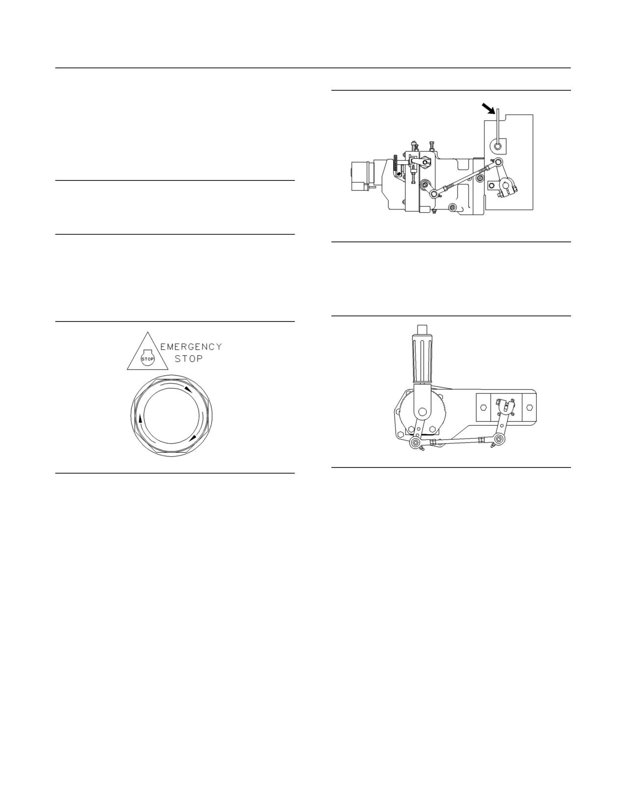
ONLY in an emergency situation. Do not use the
Emergency Stop Button for normal engine stopping.
Always start the engine according to the procedure
After an emergency stop, DO NOT start the engine
that is described in this Operation and Maintenance
until the problem that caused the emergency stop
Manual, “Engine Starting” topic (Operation Section).
has been corrected.
Knowing the correct procedure will help to prevent
major damage to the engine components. Knowing
On the initial start-up of a new engine or an engine
the procedure will also help to prevent personal
that has been overhauled, be prepared to stop the
injury.
engine if an overspeed condition occurs. This may
be accomplished by shutting off the fuel supply to
To ensure that the jacket water heater (if equipped)
the engine and/or shutting off the air supply to the
and/or the lube oil heater (if equipped) is working
engine.
properly, check the water temperature gauge
and the oil temperature gauge during the heater
To stop an electronically controlled engine, cut the
operation.
power to the engine.
14
Product Information Section
Model Views
Product Information
Section
Model Views
i01369271
Model View Illustrations
SMCS Code: 1000
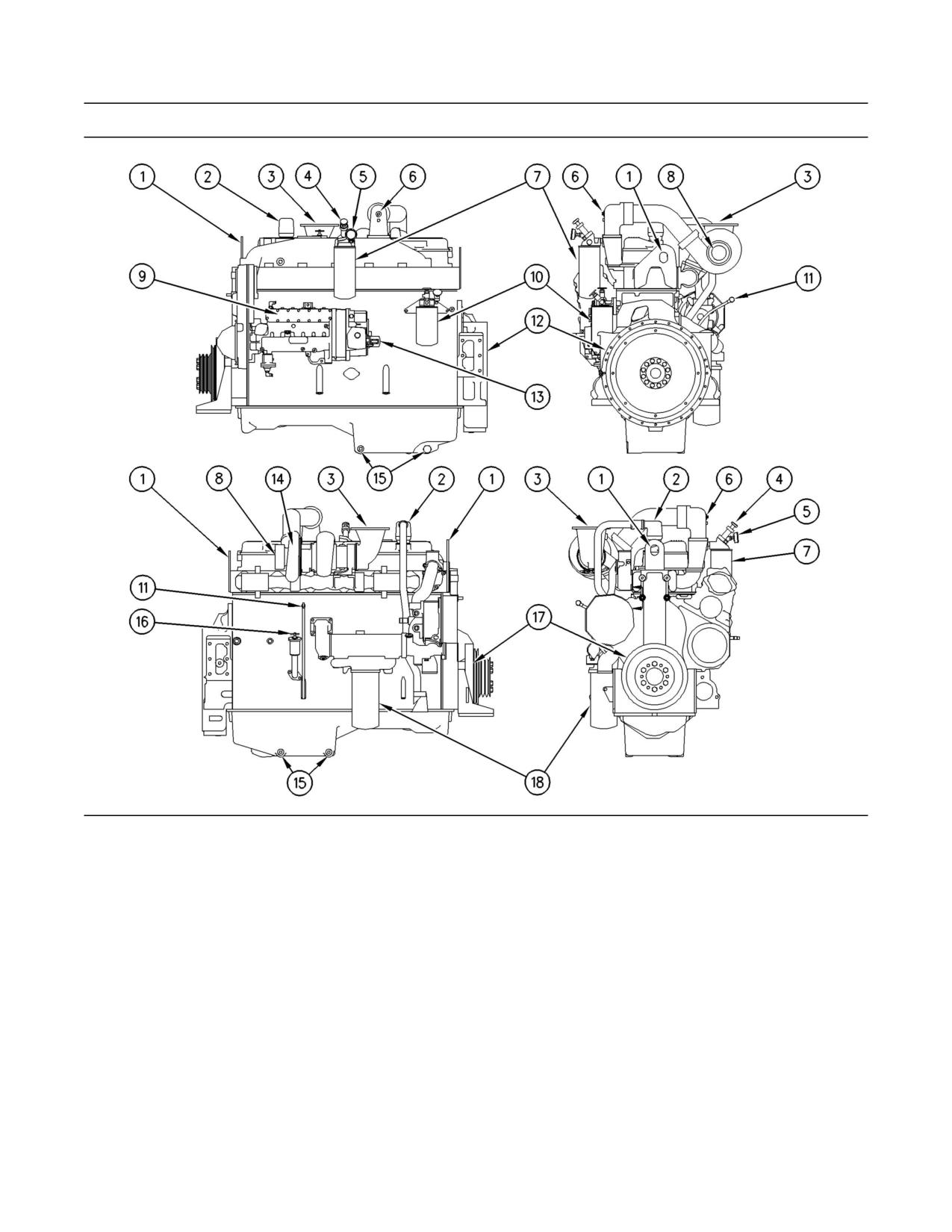
The following model views show typical 3406C
Industrial Engine features. Due to individual
applications, your engine may appear different from
the illustrations.
15
Product Information Section
Model Views
g00722253
Illustration 12
(1) Lifting eye
(7) Fuel filter
(13) Service hour meter
(2) Crankcase breather
(8) Air inlet
(14) Turbocharger
(3) Exhaust
(9) Fuel pump
(15) Oil drain plugs
(4) Fuel priming pump
(10) SCA element (if equipped)
(16) Oil filler cap
(5) Fuel pressure gauge
(11) Oil level gauge
(17) Crankshaft vibration damper
(6) Either starting aid (if equipped)
(12) Flywheel housing
(18) Oil filter
i01369284
A mechanical governor controls the fuel injection
pump output. The output maintains the desired
Engine Description
engine speed. An automatic timing advance
provides the best fuel injection timing over the full
SMCS Code: 1000
range of engine speeds.
Engine Information
The fuel ratio control is located on the governor. The
fuel ratio control restricts the fuel rack movement.
The 3406C Industrial Engine is designed
Only the proper amount of fuel is allowed to be
primarily for agricultural, petroleum, and auxiliary
injected into the cylinders during acceleration. This
applications.
minimizes exhaust smoke.
16
Product Information Section
Model Views
Inlet air is filtered by an air cleaner. The air is
• Fuel
compressed by a turbocharger before the air enters
the engine cylinders. The turbocharger is driven by
• Fuel filter
engine exhaust. The engines can be turbocharged.
The engines can also be turbocharged with jacket
Engine Specifications
water aftercooling.
Note: The front end of the engine is opposite the
The engine is a four cycle engine. Each cylinder
flywheel end of the engine. The left and the right
head has two inlet valves and two exhaust valves.
sides of the engine are determined from the flywheel
The rocker arms and the valves are actuated by the
end. The number 1 cylinder is the front cylinder.
camshaft. The action is performed by mechanical
lifters and push rods.
Engine Cooling and Lubrication
The cooling system consists of the following
components:
• Centrifugal pump that is driven by gears
• Thermostats which regulate the engine coolant
temperature
• Oil cooler
g00284836
• A radiator or expansion tank (incorporating a
Illustration 13
shunt system)
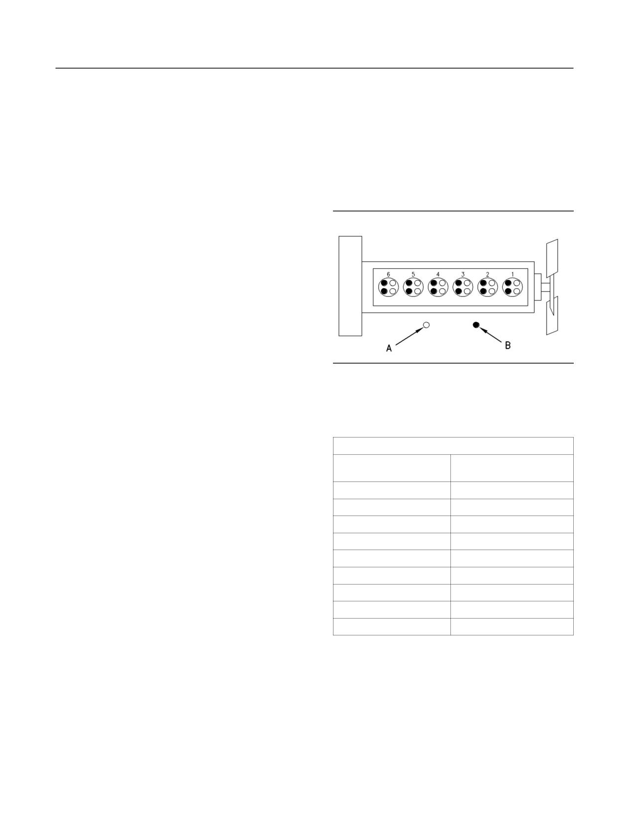
Cylinder and valve locations
(A) Inlet valves
The engine lubricating oil, that is supplied by a gear
(B) Exhaust valves
type pump, is cooled. The engine lubricating oil is
also filtered. Bypass valves provide unrestricted
Table 1
flow of lubrication oil to the engine components
3406C Industrial Engine Specifications
during the following conditions:
Cylinders and
6 cylinder in-line block
Arrangement
• High oil viscosity
Bore
137 mm (5.4 inch)
• Plugged oil cooler or plugged oil filter elements
Stroke
165 mm (6.5 inch)
(paper cartridge)
Compression Ratio
16:25:1
Engine efficiency, efficiency of emission
controls, and engine performance depend on
Aspiration
T or TA(1)
adherence to proper operation and maintenance
Displacement
14.6 L (893 in3)
recommendations. Engine performance and
efficiency also depend on the following items:
Firing Order
1-5-3-6-2-4
Rotation (flywheel end)
Counterclockwise
• Use of recommended coolant/antifreeze
Valve Lash (inlet)
0.38 mm (.015 inch)
• Use of recommended fuels
Valve Lash (exhaust)
0.76 mm (.030 inch)
(1) Turbocharged or Turbocharged and Aftercooled
• Use of recommended lubrication oils
Refer to the recommended Maintenance Interval
Schedule found within this publication in order to
maintain the following emission related components:
• Air cleaner
• Engine oil
• Oil filter
17
Product Information Section
Product Identification Information
i00061495
Product Identification
Information Plate
Information
SMCS Code: 1000
i00826199
Engine Identification
SMCS Code: 1000
Caterpillar engines are identified with serial
numbers, with performance specification numbers,
and with arrangement numbers. In some of the
cases, modification numbers are used. These
numbers are shown on the serial number plate that
is mounted on the engine.
The numbers for fuel setting information for
electronic engines are stored within the personality
g00102789
module. These numbers can be read by using
Illustration 15
Caterpillar electronic service tools.
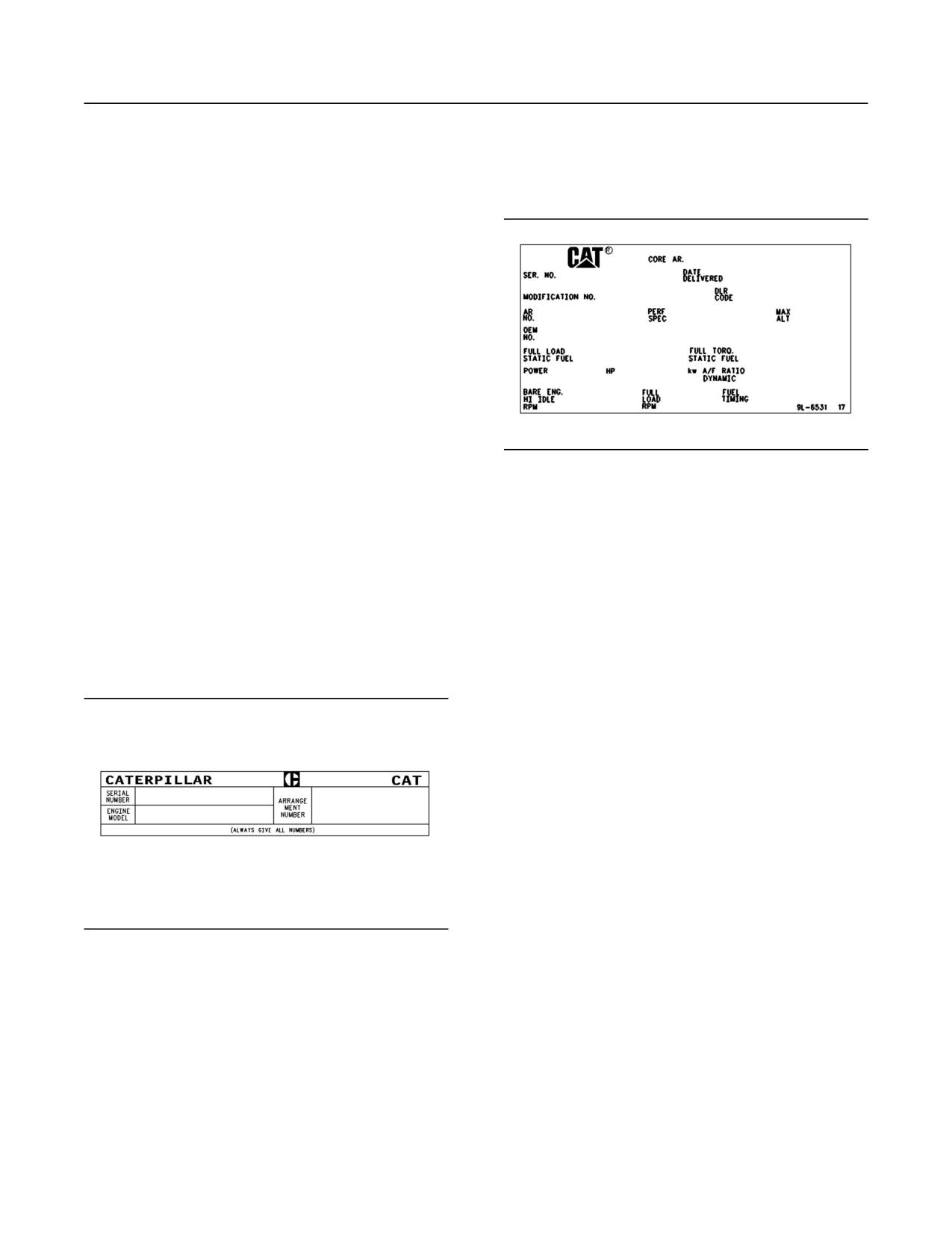
The Information Plate is on the valve cover. The
Caterpillar dealers need these numbers in order to
following information is stamped on the Information
determine the components that were included with
Plate: engine’s maximum altitude, horsepower,
the engine. This permits accurate identification of
high idle, full load rpm, fuel settings, and other
replacement part numbers.
information.
i01369380
i00610276
Serial Number Plate
Reference Numbers
SMCS Code: 1000
SMCS Code: 1000
Information for the following items may be needed
to order parts. Locate the information for your
engine. Record the information on the appropriate
space. Make a copy of this list for a record. Retain
the information for future reference.
Record for Reference
Engine Model
______________________________________________
Engine Serial No.
__________________________________________
Engine Arrangement No.
________________________________
g00722314
Illustration 14
Modification No.
___________________________________________
Typical serial number plate
Engine Low Idle rpm
_____________________________________
The Serial Number Plate is located on the left side
of the cylinder block near the rear of the engine.
____________________________________
Engine Full Load rpm
The following information is stamped on the Serial
Performance Specification No.
_________________________
Number Plate: engine serial number, model, and
arrangement number.
Primary Fuel Filter No.
___________________________________
Water Separator Element No.
__________________________
Secondary Fuel Filter Element No. ____________________
18
Product Information Section
Product Identification Information
Lubrication Oil Filter Element No.
_____________________
Auxiliary Oil Filter Element No.
_________________________
Supplemental Coolant Additive Maintenance
Element No. (Optional)
___________________________________
Total Lubrication System Capacity
____________________
Total Cooling System Capacity
________________________
Air Cleaner Element No.
_________________________________
Fan Drive Belt No.
________________________________________
Alternator Belt No.
________________________________________
i01193826
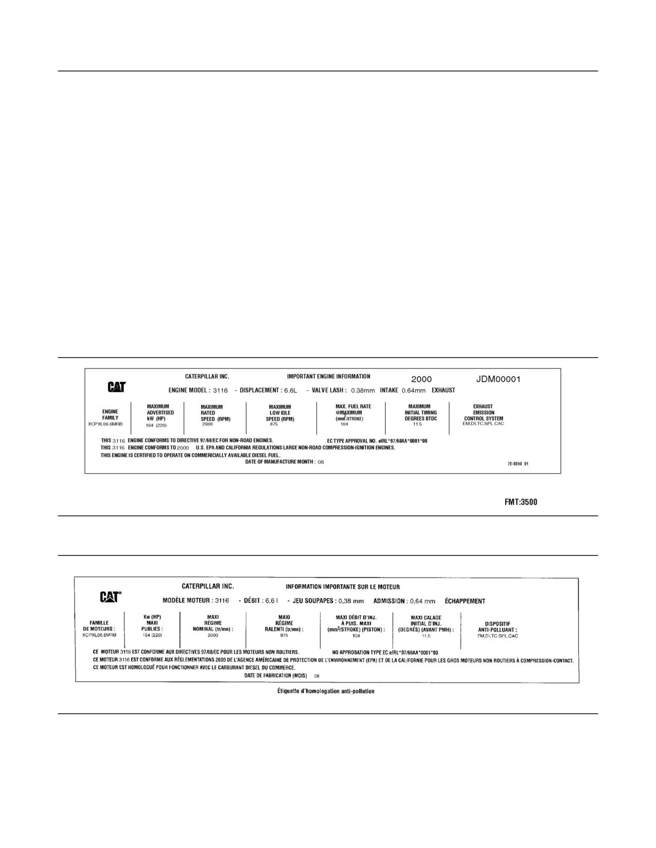
Emissions Certification Film
SMCS Code: 1000
g00638668
Illustration 16
EPA/EU Emissions Certification Film (typical example)
g00638373
Illustration 17
EPA/EU Emissions Certification Film (French-typical example)
The EPA/EU Emissions Certification Film (if
applicable) is located either on the side, the top, or
the front of the engine.
19
Operation Section
Engine Lifting and Storage
Engine Lifting with a Fuel Tank
Operation Section
Engine Lifting and Storage
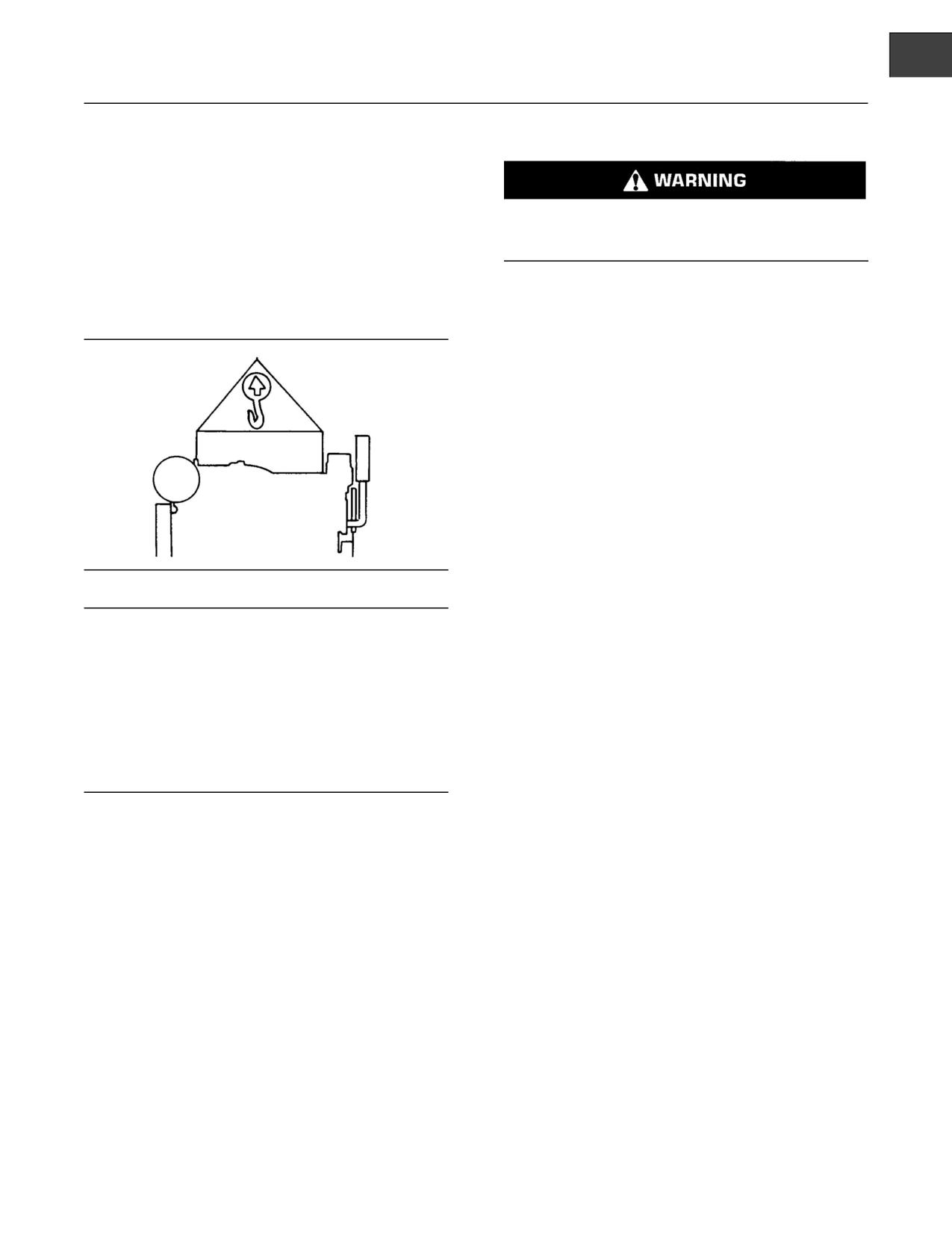
Lift eyes or tank can fail when lifting tank con-
taining fluids resulting in possible personal injury.
Drain tank of all fluids before lifting.
i01028339
Engine Lifting
Lifting the engine with a fuel tank that is mounted
to the engine requires special equipment and
SMCS Code: 1000; 1122
procedures. Do not lift the unit with fuel in the fuel
tank. Consult your Caterpillar dealer for information
regarding fixtures for proper lifting of your complete
package.
i00777190
Engine Storage
SMCS Code: 1000
If the engine will not be started for several weeks,
the lubricating oil will drain from the cylinder walls
and from the piston rings. Rust can form on the
cylinder liner surface. Rust on the cylinder liner
g00103219
Illustration 18
surface will cause increased engine wear and a
reduction in engine service life.
NOTICE
Never bend the eyebolts and the brackets. Only load
To help prevent excessive engine wear, use the
the eyebolts and the brackets under tension. Remem-
following guidelines:
ber that the capacity of an eyebolt is less as the angle
between the supporting members and the object be-
• Complete all of the lubrication recommendations
comes less than 90 degrees.
that are listed in this Operation and Maintenance
Manual, “Maintenance Interval Schedule”
When it is necessary to remove a component at an
(Maintenance Section).
angle, only use a link bracket that is properly rated for
the weight.
• If freezing temperatures are expected, check the
cooling system for adequate protection against
freezing. See this Operation and Maintenance
Use a hoist to remove heavy components. Use
Manual, “General Coolant Information”
an adjustable lifting beam to lift the engine. All
(Maintenance Section).
supporting members (chains and cables) should
be parallel to each other. The chains and cables
If an engine is out of operation and if use of the
should be perpendicular to the top of the object
engine is not planned, special precautions should
that is being lifted.
be made. If the engine will be stored for more than
one month, a complete protection procedure is
Some removals require lifting the fixtures in order to
recommended.
obtain proper balance and safety.
For more detailed information on engine storage,
To remove the engine ONLY, use the lifting eyes that
see Special Instruction, SEHS9031, “Storage
are on the engine.
Procedure For Caterpillar Products”.
Lifting eyes are designed and installed for the
Your Caterpillar dealer can assist in preparing the
specific engine arrangement. Alterations to the lifting
engine for extended storage periods.
eyes and/or the engine make the lifting eyes and
the lifting fixtures obsolete. If alterations are made,
ensure that proper lifting devices are provided.
Consult your Caterpillar dealer for information
regarding fixtures for proper engine lifting.
20
Operation Section
Gauges and Indicators
Gauges and Indicators
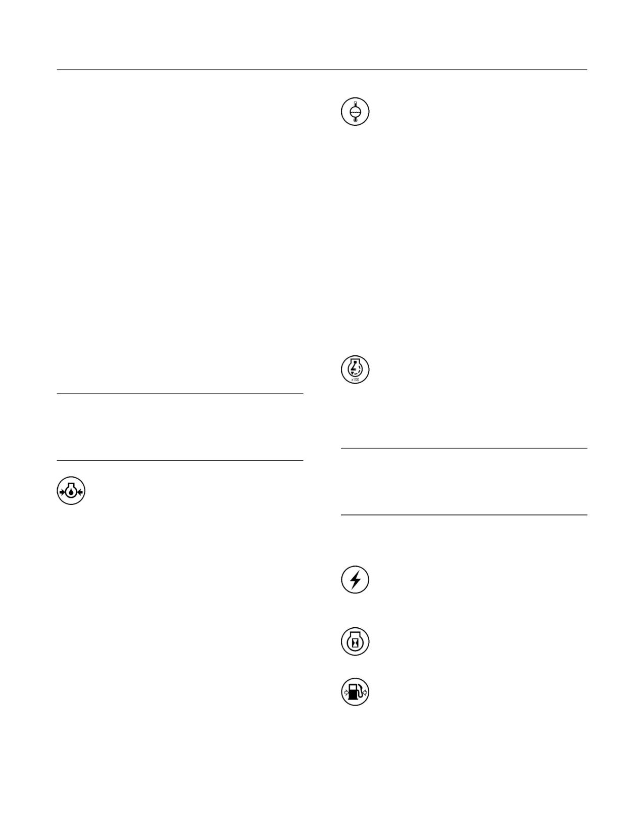
Jacket Water Coolant Temperature -
Typical temperature range is 87 to 98 C
i01369505
(189 to 208 F). The maximum allowable
temperature with the pressurized cooling system is
Gauges and Indicators
104
C (219 F). Higher temperatures may occur
under certain conditions. The water temperature
SMCS Code: 1900; 7450
reading may vary according to load. The reading
should never exceed the boiling point for the
Your engine may not have the same gauges or all of
pressurized system that is being used.
the gauges that are described. For more information
about the gauge package, see the OEM information.
If the engine is operating above the normal range
and steam becomes apparent, perform the following
Gauges provide indications of engine performance.
procedure:
Ensure that the gauges are in good working order.
Determine the normal operating range by observing
1. Reduce the load and the engine speed (rpm).
the gauges over a period of time.
2. Inspect the cooling system for leaks.
Noticeable changes in gauge readings indicate
a potential problem with a gauge or with the
3. Determine if the engine must be shut down
engine. Problems may also be indicated by gauge
immediately or if the engine can be cooled by
readings that change even if the readings are
reducing the load.
within specifications. Determine the cause of any
significant change in the readings, and/or correct
Tachometer - This gauge indicates engine
the cause of any significant change in the readings.
speed (rpm). When the throttle control
Consult your Caterpillar dealer for assistance.
lever is moved to the full throttle position
without load, the engine is running at high idle. The
NOTICE
engine is running at the full load rpm when the
Be ready to activate the engine shutoff manually, if
throttle control lever is at the full throttle position
there is no oil pressure . Damage to the engine will
with maximum rated load.
result if the engine continues to run without the correct
oil pressure.
NOTICE
Engine overspeed may cause serious damage.
Engine Oil Pressure - Typical oil pressure
for an engine at rated speed with
Keep the tachometer indicator in the green operating
SAE 10W30 or with SAE 15W40 is
range.
275 to 606 kPa (40 to 88 psi).
Note: The high idle speed (rpm) and the full load
A lower oil pressure is normal at low idle. If the load
speed (rpm) are stamped on the Information Plate.
is stable and the gauge reading changes, perform
the following procedure:
Ammeter - This gauge indicates the
amount of charge or discharge in the
1. Remove the load.
battery charging circuit. Operation of the
indicator should be to the right side of “0”(zero).
2. Reduce engine speed to low idle.
Service Hour Meter - This gauge indicates
3. Check and maintain the oil level.
the total number of clock hours that the
engine has operated.
The minimum recommended oil pressure at 600
rpm is 103 kPa (15 psi). If low oil pressure or no
oil pressure is indicated, stop the engine and
Fuel Pressure - This gauge indicates
determine the cause of the problem. Refer to
fuel pressure to the injection pump. The
Troubleshooting for further information or consult
indicator should indicate the “NORMAL”
with your Caterpillar dealer.
range. If the indicator moves to the “OUT” position
or registers below 160 kPa (23 psi) when equipped
with a numerical gauge, the engine will not operate
properly. A decrease in fuel pressure usually
indicates a plugged fuel filter.
21
Operation Section
Engine Features and Controls
Overspeed Shutoffs
Engine Features and
Controls
i01369587
Engine Shutoffs and Engine
Alarms
SMCS Code: 1900; 7400; 7418
Shutoffs
Shutoffs and alarms are electrically operated or
mechanically operated. The operation of all electric
g00293335
Illustration 19
shutoffs and alarms utilize components which
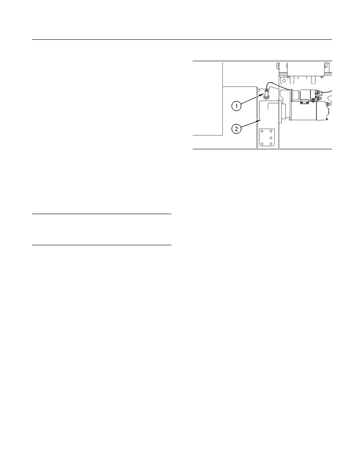
(1) Magnetic pickup
actuate switches in a sensing unit.
(2) Flywheel housing
Shutoffs are set at critical levels for the following
The magnetic pickup senses the passage of
items: operating temperature, operating pressure,
the teeth that are on the flywheel ring gear.
operating coolant level, and operating speed (rpm).
The Electronic Overspeed Switch is set at 118
The particular shutoff may need to be reset before
percent of the rated engine speed. If the engine
the engine will start.
speed increases above the overspeed setting, the
magnetic pickup will sense the overspeed. A signal
NOTICE
is sent to the Electronic Overspeed Switch. The
Always determine the cause of the engine shutdown.
Electronic Overspeed Switch activates both the air
Make necessary repairs before attempting to restart
shutoff solenoid (if equipped) and the fuel shutoff
the engine.
solenoid.
The shutoffs must be reset before the engine will
Be familiar with the following items:
restart. The air shutoff lever that is located at the
top of the air inlet housing must be manually reset.
• Types and locations of shutoff
The cause of the overspeed must be determined
before the engine is restarted.
• Conditions which cause each shutoff to function
• The resetting procedure that is required to restart
Alarms
the engine
Alarms consist of a switch and a contactor. The
switches are wired to the contactors. The contactors
Air Shutoff Solenoid (If Equipped)
activate alarm circuits in an annunciator panel.
Your engine may be equipped with the following
This optional solenoid is located on top of the
switches:
engine. The air shutoff is part of the air inlet
system. When the solenoid is activated, the
Engine oil pressure - The engine oil pressure switch
solenoid mechanically shuts off the inlet air to the
indicates when oil pressure drops below rated
engine. The solenoid can be activated only by the
system pressure.
overspeed switch or by the emergency stop push
button (ESPB). The cause of the shutoff should be
Coolant level - The low coolant level switch
determined before the engine is restarted.
indicates when the coolant level is low.
Fuel Shutoff Solenoid
Coolant temperature - The coolant temperature
switch indicates high jacket water coolant
The fuel shutoff solenoid is located on the governor
temperature.
or the fuel shutoff solenoid is located on the fuel
injection pump. When the fuel shutoff solenoid is
Note: The sensing element of the coolant
activated, the solenoid moves the fuel rack “OFF”.
temperature switch must be submerged in coolant
The fuel shutoff solenoid moves the fuel rack
in order to operate.
directly or the fuel shutoff solenoid moves the fuel
rack through the governor.
22
Operation Section
Engine Features and Controls
Engines may be equipped with alarms in order
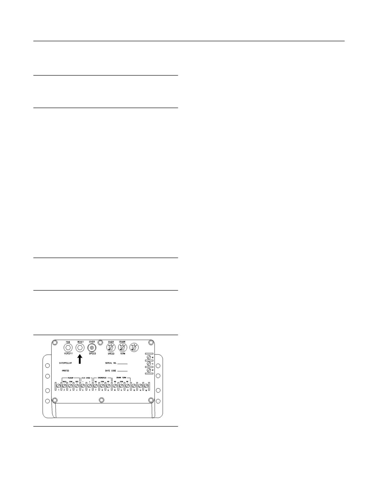
The overspeed shutoff switch is located in the
to alert the operator when undesirable operating
junction box. The overspeed shutoff switch must be
conditions occur.
reset before you can restart the engine. To reset
the switch, push the “RESET” button. The button
will remain in this position unless an overspeed
NOTICE
condition occurs.
When an alarm is activated, corrective measures must
be taken before the situation becomes an emergency
in order to avoid possible engine damage.
The Electronic Overspeed Switch with Cranking
Termination has a 75 percent “VERIFY” button, a
“RESET” button, and an “OVERSPEED” indicator
If corrective measures are not taken within a
lamp.
reasonable time, engine damage could result. The
alarm will continue until the condition is corrected.
The Electronic Overspeed Shutoff Switch with
The alarm may need to be reset.
Cranking Termination has a sensing circuit which
prevents the starter pinion from remaining engaged
A switch may be installed in the alarm while the
in the flywheel at excessive rpm. Crank Termination
engine is stopped for repairs. Before the engine is
has an adjustable engine speed setting. This
started, ensure that the switch is moved to the ON
signals the starter motor when the engine is firing.
position and that the warning lights are flashing.
Cranking must be terminated. Once the speed
The engine will not be protected if the switch is left
setting is reached, a switch opens. This will start the
in the OFF position.
engine hour meter.
Once the starting motor cranks the engine, the
Testing the Shutoff and Alarm
pinion gear can remain engaged with the flywheel
System
as the engine speed increases. The magnetic
pickup opens the circuit to the starting motor at 400
Most control panels are equipped with a lamp test
rpm. This will allow the pinion gear to disengage.
switch. Turn the switch to the ON position in order
to check the indicator lights for proper operation.
The circuit will remain open until the flywheel stops.
Replace worn bulbs immediately.
This prevents energizing the starting motor circuit
again while the flywheel is turning.
NOTICE
During testing, abnormal operating conditions must be
The engine may be equipped with either an
simulated. Perform the tests correctly in order to help
Overspeed Shutoff Switch or an Electronic
prevent possible engine damage.
Overspeed Switch with Cranking Termination. Both
switches can be checked for proper operation at 75
percent of overspeed condition. Use the following
Refer to the Service Manual for more information on
procedure:
testing procedures or consult your Caterpillar dealer.
1. Determine full load speed (rpm) from the Engine
Testing of the Overspeed Switch
Information Plate.
2. Operate the engine at or slightly above the
corresponding speed (rpm) shown for the
engine. Refer to table 2.
3. Maintain the test speed (rpm). Push and hold the
“VERIFY” button. The engine should stop. If the
engine does not stop at the specified test speed
(rpm), contact your Caterpillar dealer.
g00291056
Illustration 20
Electronic Overspeed Switch
23
Operation Section
Engine Features and Controls
Table 2
INDUSTRIAL ENGINE OVERSPEED TEST RPM
Test RPM For
Actual RPM Of
Full Load RPM
Overspeed(1)
Overspeed(2)
1500
1328
1770
1800
1593
2124
2000
1770
2360
2100
1859
2478
(1) The Test RPM for Overspeed is slower than the Full Load
RPM. Multiply the Full Load RPM by 0.885. The product is
the Test RPM.
(2) Multiply the Full Load RPM by 1.18. The product is the Actual
RPM of Overspeed
Note: The “OVERSPEED” lamp will illuminate as the
engine stops. Push the “RESET” button before you
restart the engine.
24
Operation Section
Engine Starting
• Do not start the engine or move any of the
Engine Starting
controls if there is a “DO NOT OPERATE” warning
tag or similar warning tag attached to the start
i01197471
switch or to the controls.
Before Starting Engine
• Ensure that the areas around the rotating parts
are clear.
SMCS Code: 1000; 1400; 1450
All of the guards must be put in place. Check for
•
Perform the required daily maintenance and
damaged guards or for missing guards. Repair
other periodic maintenance before the engine is
any damaged guards. Replace damaged guards
started. Inspect the engine compartment. This
and/or missing guards.
inspection can help prevent major repairs at a
later date. Refer to the Operation and Maintenance
• Disconnect any battery chargers that are not
Manual, “Maintenance Interval Schedule” for more
protected against the high current drain that
information.
is created when the electric starting motor (if
equipped) is engaged. Check electrical cables
• For the maximum service life of the engine,
and check the battery for poor connections and
make a thorough inspection before the engine
for corrosion.
is started. Look for the following items: oil leaks,
coolant leaks, loose bolts, and trash buildup.
• Reset all of the shutoffs or alarm components.
Remove trash buildup and arrange for repairs,
as needed.
• Check the engine lubrication oil level. Maintain
the oil level between the “ADD” mark and the
• Inspect the cooling system hoses for cracks and
“FULL” mark on the oil level gauge.
for loose clamps.
•
Check the coolant level. Observe the coolant
• Inspect the alternator and accessory drive belts
level in the coolant recovery tank (if equipped).
for cracks, breaks, and other damage.
Maintain the coolant level to the “FULL” mark on
the coolant recovery tank.
• Inspect the wiring for loose connections and for
worn wires or frayed wires.
• If the engine is not equipped with a coolant
recovery tank maintain the coolant level within
• Check the fuel supply. Drain water from the water
13 mm (0.5 inch) of the bottom of the filler pipe.
separator (if equipped). Open the fuel supply
If the engine is equipped with a sight glass,
valve.
maintain the coolant level in the sight glass.
NOTICE
• Observe the air cleaner service indicator (if
All valves in the fuel return line must be open before
equipped). Service the air cleaner when the
and during engine operation to help prevent high fuel
yellow diaphragm enters the red zone, or when
pressure. High fuel pressure may cause filter housing
the red piston locks in the visible position.
failure or other damage.
• Ensure that any driven equipment has been
disengaged. Remove any electrical loads.
If the engine has not been started for several
weeks, fuel may have drained from the fuel system.
Air may have entered the filter housing. Also, when
fuel filters have been changed, some air pockets
will be trapped in the engine. In these instances,
prime the fuel system. Refer to the Operation and
Maintenance Manual, “Fuel System - Prime” for
more information on priming the fuel system.
Engine exhaust contains products of combustion
which may be harmful to your health. Always start
and operate the engine in a well ventilated area
and, if in an enclosed area, vent the exhaust to the
outside.
25
Operation Section
Engine Starting
i00970006
Starting the Engine
When using starting fluid (ether), follow the man-
ufacturer’s instructions carefully. Use the starting
SMCS Code: 1000; 1450
fluid sparingly and spray only while cranking the
Refer to the Service Manual for your type of controls.
engine. Failure to do so could result in an explo-
sion and/or fire and personal injury.
Use the following procedure to start the engine.
1. Place the manual stop control (if equipped) in
NOTICE
the RUN position. Turn the ignition switch to the
The optional ether starting aid is the only starting fluid
RUN position. Advance the throttle in order to
system that is recommended on the engine.
supply fuel to the engine.
2. Turn the ignition switch to the START position in
Startability will be improved at temperatures below
order to crank the engine.
-18
C (0 F) from the use of a jacket water heater
or extra battery capacity.
Allow the ignition switch to return to the RUN
position as soon as the engine starts.
When No. 2 diesel fuel is used, the following items
provide a means of minimizing starting problems
and fuel problems in cold weather: starting aids,
NOTICE
engine oil pan heaters, jacket water heaters, fuel
Oil pressure should rise within 15 seconds after the
heaters, and fuel line insulation.
engine starts. Do not increase engine speed until the
oil pressure gauge indicates normal. If oil pressure
For temperatures below -23 C (-10 F), consult
is not indicated on the gauge within 15 seconds, DO
your Caterpillar dealer.
NOT operate the engine. STOP the engine, investigate
and correct the cause.
Use the procedure that follows for cold weather
starting.
3. Move the throttle to approximately one quarter
of the engine rpm.
Note: If the engine has not been run for several
weeks, fuel may have drained. Air may have moved
4. Allow the engine to idle for three to five minutes,
into the filter housing. Also, when fuel filters have
or allow the engine to idle until the water
been changed, some air will be left in the filter
temperature indicator begins to rise. The engine
housing. Refer to the Operation and Maintenance
should run at low idle smoothly until speed
Manual for more information on priming the fuel
is gradually increased to high idle. Allow the
system.
white smoke to disperse before proceeding with
normal operation.
NOTICE
Do not engage the starting motor when flywheel is
To minimize white smoke for cold weather
turning. Do not start the engine under load.
starting, start the engine and allow the engine
to idle for 30 seconds. Increase the rpm until
If the engine fails to start within 30 seconds, release
the engine speed reaches 1200 rpm. Return the
the starter switch or button and wait two minutes to
engine to low idle rpm.
allow the starting motor to cool before attempting to
5. Operate the engine at low load until all systems
start the engine again.
reach operating temperature. Check the gauges
during the warm-up period.
1. Turn the ignition switch to the RUN position.
Advance the throttle in order to supply fuel to
the engine.
i00998863
Cold Weather Starting
NOTICE
Excessive ether can cause piston and piston ring dam-
SMCS Code: 1000; 1250; 1450; 1453; 1456; 1900
age. Use ether for cold starting purposes only. Do not
use excessive starting fluid while starting the engine.
Refer to the Operation and Maintenance Manual
Do not use starting fluid after the engine is running.
that is for the control panels for detailed information
on the control panels.
26
Operation Section
Engine Starting
2. If equipped, press the “Starting Aid” switch in
Many batteries which are considered unusable are
order to improve cold weather starting. Release
still rechargeable. After jump starting, the alternator
the “Starting Aid” switch when the engine starts.
may not be able to fully recharge batteries that
Use the starting fluid sparingly. Carefully follow
are severely discharged. The batteries must be
the instructions of the OEM.
charged to the proper voltage with a battery
charger. For information on testing and charging,
refer to the Special Instruction, SEHS7633, “Battery
NOTICE
Oil pressure should rise within 15 seconds after the
Test Procedure”.
engine starts. Do not increase engine speed until the
oil pressure gauge indicates normal. If oil pressure
NOTICE
is not indicated on the gauge within 15 seconds, DO
Using a battery source with the same voltage as the
NOT operate the engine. STOP the engine, investigate
electric starting motor. Use ONLY equal voltage for
and correct the cause.
jump starting. The use of higher voltage will damage
the electrical system.
3. Increase the engine rpm to approximately 1/4 of
Do not reverse the battery cables. The alternator can
the full load rpm.
be damaged. Attach ground cable last and remove
first.
4. Allow the engine to idle for three to five minutes,
or allow the engine to idle until the water
When using an external electrical source to start the
temperature indicator begins to rise. The engine
engine, turn the engine control switch to the “OFF” po-
should run at low idle smoothly until speed
sition. Turn all electrical accessories OFF before at-
is gradually increased to high idle. Allow the
taching the jump start cables.
white smoke to disperse before proceeding with
normal operation.
Ensure that the main power switch is in the OFF posi-
tion before attaching the jump start cables to the en-
5. Operate the engine at low load until all systems
gine being started.
reach operating temperature. Check the gauges
during the warm-up period.
1. Turn the start switch on the stalled engine to the
OFF position. Turn off all accessories.
i01037941
Starting with Jump Start
2. Connect one positive end of the jump start cable
to the positive cable terminal of the discharged
Cables
battery. Connect the other positive end of the
jump start cable to the positive cable terminal
SMCS Code: 1000; 1401; 1402; 1900
of the electrical source.
3. Connect one negative end of the jump start cable
to the negative cable terminal of the electrical
source. Connect the other negative end of the
Improper jump start cable connections can cause
jump start cable to the engine block or to the
an explosion resulting in personal injury.
chassis ground. This procedure helps to prevent
potential sparks from igniting combustible gases
Prevent sparks near the batteries. Sparks could
that are produced by some batteries.
cause vapors to explode. Do not allow jump start
cable ends to contact each other or the engine.
4. Charge the batteries. The engine will not
continue to run after starting if the batteries have
If the installation is not equipped with a backup
not been charged.
battery system, it may be necessary to start the
engine from an external electrical source.
5. Start the engine.
First, determine the reason that it is necessary to
6. Immediately after the stalled engine is started,
start with power from an external source. Refer to
disconnect the jump start cables in reverse order.
Special Instruction, SEHS7768, “Use of the 6V-2150
Starting/Charging Analyzer”.
Refer to the Electrical Schematic for your engine.
Consult your Caterpillar dealer for more information.
27
Operation Section
Engine Starting
i01043333
i00830307
After Starting Engine
Air Starting
SMCS Code: 1000
SMCS Code: 1451
Note: In temperatures from 0 to 60 C (32 to 140 F),
For good life of the air starting motor, the air supply
the warm-up time is approximately five minutes. In
must be free from dirt and water.
temperatures below 0 C (32 F), additional warm-up
time may be required.
1. Open the drain valve and close the drain valve
in order to drain condensation and oil carryover.
Note: Ensure that the self-test for the monitoring
This drain valve is located on the bottom of the
system (if equipped) is completed before operating
air tank.
the engine under load.
2. Check the air supply pressure. The air starting
When the engine idles during warm-up, observe
motor requires a minimum of 690 kPa (100 psi)
the following conditions:
air pressure to operate properly. The maximum
air pressure must not exceed 1550 kPa (225 psi).
• Check for any fluid or for any air leaks at idle rpm
The normal operating air pressure will be
and at one-half full rpm (no load on the engine)
758 to 965 kPa (110 to 140 psi).
before operating the engine under load.
• Operate the engine at low idle until all systems
achieve operating temperatures. Check all
gauges during the warm-up period.
Note: Gauge readings should be observed and the
data should be recorded frequently while the engine
is operating. Comparing the data over time will
help to determine normal readings for each gauge.
Comparing data over time will also help detect
abnormal operating developments. Significant
changes in the readings should be investigated.
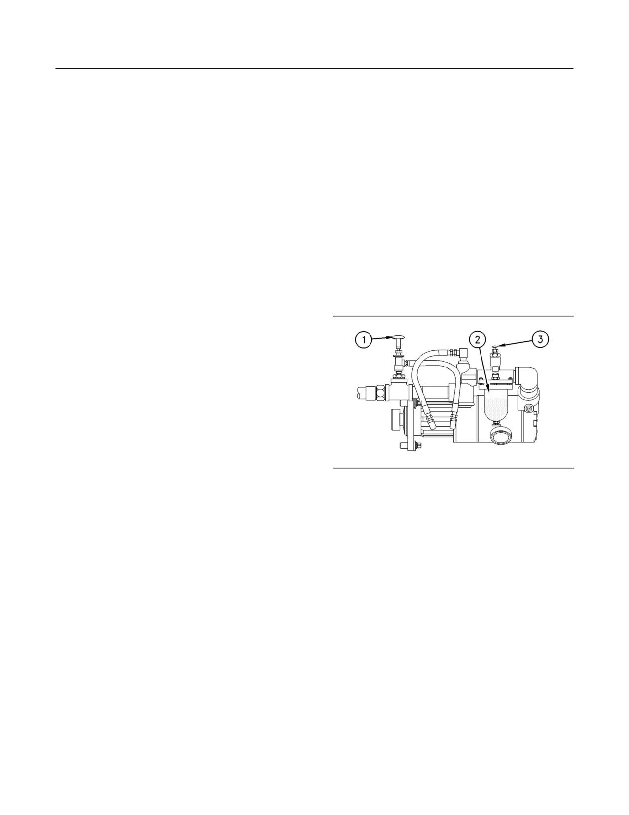
g00381232
Illustration 21
(1) Air valve
(2) Lubricator bowl
(3) Adjustment knob
3. Check the oil level in lubricator bowl (2). Keep
the bowl at least half full and add lubricant, if
necessary.
4. Press air valve (1) or press the start button for
the engine in order to crank the engine. After
the engine starts, release the air valve or release
the start button.
28
Operation Section
Engine Operation
i00808595
Engine Operation
Engine Warm-up
i00718869
SMCS Code: 1000
Engine Operation
1. Run the engine at low idle for three to five
SMCS Code: 1000
minutes, or run the engine at low idle until the
jacket water temperature starts to rise.
Proper operation and maintenance are key factors
in obtaining the maximum life and economy of
More time may be necessary when the
the engine. If the directions in the Operation and
temperature is below -18 C (0 F).
Maintenance Manual are followed, costs can
be minimized and engine service life can be
2. Check all of the gauges during the warm-up
maximized.
period.
The time that is needed for the engine to reach
3. Perform another walk-around inspection. Check
normal operating temperature can be less than the
the engine for fluid leaks and air leaks.
time needed for a walk-around inspection of the
engine.
4. Increase the rpm to the rated rpm. Check for fluid
leaks and air leaks. The engine may be operated
After the engine is started and after the engine
at full rated rpm and at full load when the engine
reaches normal operating temperature, the engine
oil temperature reaches 60 C (140 F).
can be operated at the rated rpm. The engine will
reach normal operating temperature faster when
the engine is at rated speed. The engine will reach
normal operating temperature faster when the
engine is at low power demand. This procedure is
more effective than idling the engine at no load.
The engine should reach operating temperature in
a few minutes.
Gauge readings should be observed and the data
should be recorded frequently while the engine is
operating. Comparing the data over time will help
to determine normal readings for each gauge.
Comparing data over time will also help detect
abnormal operating developments. Significant
changes in the readings should be investigated.
29
Operation Section
Engine Operation
i00162260
Fuel expands when the fuel is warmed up. The fuel
may overflow from the fuel tank. Inspect fuel lines
Engaging the Driven
for leaks. Repair the fuel lines, as needed.
Equipment
Be aware of the properties of the different fuels.
•
Use only the recommended fuels.
SMCS Code: 1000
1.
Operate the engine at one-half of the rated rpm.
• Avoid unnecessary idling.
Shut off the engine rather than idle for long periods
2.
Engage the driven equipment without a load on
of time.
the equipment.
Interrupted starts put excessive stress on the
• Observe the service indicator frequently. Keep
the air cleaner elements clean.
drive train. Interrupted starts also waste fuel. To
get the driven equipment in motion, engage the
clutch smoothly with no load on the equipment.
• Ensure that the turbochargers are operating
correctly so that the proper air/fuel ratio is
This method should produce a start that is
smooth and easy. The engine rpm should not
maintained. Clean exhaust indicates proper
functioning.
increase and the clutch should not slip.
3.
Ensure that the engine gauges register in the
• Maintain a good electrical system.
normal ranges when the engine is operating
One defective battery cell will overwork the
at one-half of the rated rpm. Ensure that any
alternator. This will consume excess power and
gauges for the equipment register in the normal
excess fuel.
ranges.
4.
Increase the engine rpm to the rated rpm. Always
• Ensure that the belts are properly adjusted. The
belts should be in good condition.
increase the engine rpm to the rated rpm before
the load is applied.
Ensure that all of the connections of the hoses
•
are tight. The connections should not leak.
5.
Apply the load. Begin operating the engine at
low load. Check the gauges and equipment for
proper operation. After normal oil pressure is
• Ensure that the driven equipment is in good
working order.
reached and the temperature gauge begins to
move, the engine may be operated at full load.
Cold engines consume excess fuel. Utilize heat
•
from the jacket water system and the exhaust
Extended operation at low idle or at reduced
system, when possible. Keep cooling system
load may cause increased oil consumption and
components clean and keep cooling system
carbon buildup in the cylinders. This carbon
components in good repair. Never operate the
buildup results in a loss of power and/or poor
performance. When the engine is operated at
engine without water temperature regulators.
reduced load, the engine should be fully loaded
All of these items will help maintain operating
temperatures.
in four hour increments. This procedure burns
excess carbon from the cylinders. Check the
gauges and equipment frequently when the
• Settings for the fuel system and the limits for the
operating altitude are stamped on the Engine
engine is operated under load.
Information Plate. If an engine is moved to a
higher altitude, the settings must be changed
i00165110
by a Caterpillar dealer. Changing the settings
will help prevent damage to the turbocharger.
Fuel Conservation Practices
Changing the settings will help to provide the
maximum efficiency for the engine. Engines can
SMCS Code: 1000; 1250
be operated safely at higher altitudes, but the
engines will deliver less horsepower. The fuel
The efficiency of the engine can affect the fuel
settings should be changed by a Caterpillar
economy. Caterpillar’s design and technology in
dealer in order to obtain the rated horsepower.
manufacturing provides maximum fuel efficiency
in all applications. Follow the recommended
procedures in order to attain optimum performance
for the life of the engine.
• Avoid spilling fuel.
30
Operation Section
Engine Stopping
Engine Stopping
i01057253
Emergency Stopping
SMCS Code: 1000; 7418
NOTICE
Emergency shutoff controls are for EMERGENCY use
ONLY. DO NOT use emergency shutoff devices or
controls for normal stopping procedure.
g00723091
Ensure that any components for the external system
Illustration 23
that support the engine operation are secured after
Typical Woodward actuator control lever
the engine is stopped.
If the engine is equipped with a Woodward Actuator,
move the control lever to the “FUEL OFF” position.
Emergency Stop Button
g00723092
g00104303
Illustration 24
Illustration 22
Typical mechanical governor control
Typical emergency stop button
If the engine is equipped with a Mechanical
The emergency stop button is in the OUT position
governor control, move the control lever to the FUEL
for normal engine operation. Push the emergency
OFF position.
stop button. The engine will not start when the
button is locked. Turn the button clockwise in order
Hold the lever at the FUEL OFF position until the
to reset.
engine stops.
i01370486
Some engines are equipped with an air shutoff. The
air shutoff is located between the aftercooler and
Manual Stop Procedure
the turbocharger. If the engine is equipped with an
air shutoff lever, move the lever to the OFF position.
SMCS Code: 1000
Note: Individual applications will have different
A manual shutoff shaft will override the governor
control systems. Ensure that the shutoff procedures
control. The shaft will move the fuel control linkage
are understood. Use the following general
to the FUEL OFF position. Refer to the MODEL
guidelines in order to stop the engine.
VIEWS for the engine location of the shaft. The
engine may be stopped by using the shaft and
1. Reduce the engine speed (rpm) to low idle.
either the Woodward Actuator (if equipped) or the
Remove the load.
Mechanical Governor (if equipped).
31
Operation Section
Engine Stopping
2. Increase the engine speed (rpm) to no more
than one-half of the rated speed (rpm). Perform
this procedure for three to five minutes in order
to cool the engine. Reduce the engine speed
(rpm) to low idle.
3. After the cool down period, turn the start switch
to the OFF position.
i01197515
After Stopping Engine
SMCS Code: 1000
• Check the crankcase oil level. Maintain the oil
level between the “ADD” mark and the “FULL”
mark on the oil level gauge.
• If necessary, perform minor adjustments. Repair
any leaks and tighten any loose bolts.
• Note the service hour meter reading. Perform
the maintenance that is in the Operation and
Maintenance Manual, “Maintenance Interval
Schedule”.
• Fill the fuel tank in order to help prevent
accumulation of moisture in the fuel. Do not
overfill the fuel tank.
NOTICE
Only use antifreeze/coolant mixtures recommended in
the Coolant Specifications that are in the Operation
and Maintenance Manual. Failure to do so can cause
engine damage.
• Allow the engine to cool. Check the coolant level.
Maintain the cooling system at 13 mm (0.5 inch)
from the bottom of the pipe for filling.
• If freezing temperatures are expected, check
the coolant for proper antifreeze protection. The
cooling system must be protected against freezing
to the lowest expected outside temperature. Add
the proper coolant/water mixture, if necessary.
• Perform all required periodic maintenance on all
driven equipment. This maintenance is outlined in
the instructions from the OEM.
32
Operation Section
Cold Weather Operation
Quantities of No. 1 diesel fuel are limited. No.
Cold Weather Operation
1 diesel fuels are usually available during the
months of the winter in the colder climates. During
i00169595
cold weather operation, if No. 1 diesel fuel is not
available, use No. 2 diesel fuel, if necessary.
Radiator Restrictions
There are three major differences between No. 1
SMCS Code: 1353; 1396
and No. 2 diesel fuel. No. 1 diesel fuel has the
following properties:
Caterpillar discourages the use of airflow restriction
devices that are mounted in front of radiators. Airflow
• Lower cloud point
restriction can cause the following conditions:
• Lower pour point
• High exhaust temperatures
• Lower rating of kJ (BTU) per unit volume of fuel
• Power loss
When No. 1 diesel fuel is used, a decrease in
• Excessive fan usage
power and in fuel efficiency may be noticed. Other
operating effects should not be experienced.
• Reduction in fuel economy
The cloud point is the temperature when a cloud
If an airflow restriction device must be used, the
of wax crystals begins to form in the fuel. These
device should have a permanent opening directly
crystals can cause the fuel filters to plug. The
in line with the fan hub. The device must have a
pour point is the temperature when diesel fuel will
minimum opening dimension of at least 770 cm2
thicken. The diesel fuel becomes more resistant to
(120 in2).
flow through fuel pumps and through fuel lines.
A centered opening that is directly in line with
Be aware of these values when diesel fuel is
the fan hub is specified in order to prevent an
purchased. Anticipate the average ambient
interrupted airflow on the fan blades. Interrupted
temperature within the area that the engine will be
airflow on the fan blades could cause a fan failure.
operated. Engines that are fueled in one climate
may not operate well if the engines are moved
Caterpillar recommends a warning device for the
to another climate. Problems can result due to
inlet manifold temperature and/or the installation of
changes in temperature.
an inlet air temperature gauge. The warning device
for the inlet manifold temperature should be set at
Before troubleshooting for low power or for poor
65 C (150 F). The inlet manifold air temperature
performance in the winter, check the type of fuel
should not exceed 65 C (150 F). Temperatures
that is being used.
that exceed this limit can cause power loss and
potential engine damage.
When No. 2 diesel fuel is used the following
components provide a means of minimizing
problems in cold weather:
i01190421
Fuel and the Effect from Cold
• Starting aids
Weather
• Engine oil pan heaters
SMCS Code: 1000; 1250
• Engine coolant heaters
The following fuels are the grades that are available
• Fuel heaters
for Caterpillar engines:
Fuel line insulation
•
• No. 1
For more information on cold weather operation, see
• No. 2
Operation and Maintenance Manual, SEBU5898,
“Cold Weather Recommendations”.
• Blend of No. 1 and No. 2
No. 2 diesel fuel is the most commonly used fuel.
Either No. 1 diesel fuel or a blend of No. 1 and No.
2 is best suited for cold weather operation.
33
Operation Section
Cold Weather Operation
i01250450
Fuel Heaters
Fuel Related Components in
Fuel heaters help to prevent fuel filters from
plugging in cold weather due to waxing. A fuel
Cold Weather
heater should be installed in the fuel system before
the primary fuel filter.
SMCS Code: 1000; 1250
The following fuel heaters are recommended for
Fuel Tanks
Caterpillar engines:
Condensation can form in partially filled fuel tanks.
• 7C-3557 Fuel Heater Group
Top off the fuel tanks after you operate the engine.
7C-3558 Heater Kit
•
Fuel tanks should contain some provision for
draining water and sediment from the bottom of the
For further information on fuel heaters, consult your
tanks. Some fuel tanks use supply pipes that allow
Caterpillar dealer.
water and sediment to settle below the end of the
fuel supply pipe.
Disconnect the fuel heater in warm weather.
Some fuel tanks use supply lines that take fuel
Note: Fuel heaters that are controlled by the water
directly from the bottom of the tank. If the engine is
temperature regulator or self-regulating fuel heaters
equipped with this system, regular maintenance of
should be used with this engine. Fuel heaters
the fuel system filter is important.
that are not controlled by the water temperature
regulator can heat the fuel in excess of 65 C
Drain the water and sediment from any fuel storage
(149 F). A loss of engine power can occur if the fuel
tank at the following intervals: weekly, oil changes,
supply temperature exceeds 37 C (100 F).
and refueling of the fuel tank. This will help prevent
water and/or sediment from being pumped from the
Note: Heat exchanger type fuel heaters should have
fuel storage tank and into the engine fuel tank.
a bypass provision in order to prevent overheating
of the fuel in warm weather operation.
Fuel Filters
It is possible that a primary fuel filter is installed
between the fuel tank and the engine fuel inlet. After
you change the fuel filter, always prime the fuel
system in order to remove air bubbles from the fuel
system. Refer to the Operation and Maintenance
Manual in the Maintenance Section for more
information on priming the fuel system.
The micron rating and the location of a primary
fuel filter is important in cold weather operation.
The primary fuel filter and the fuel supply line are
the most common components that are affected by
cold fuel.
NOTICE
In order to maximize fuel system life and prevent
premature wear out from abrasive particles in the
fuel, a two micron absolute high efficiency fuel filter
is required for all Caterpillar Electronic Unit Injectors.
Caterpillar High Efficiency Fuel Filters meet these
requirements. Consult your Caterpillar dealer for the
proper part numbers.
34
Maintenance Section
Torque Specifications
i00621349
Maintenance Section
Standard Torque for Inch
Fasteners
Torque Specifications
SMCS Code: 7553
i01252954
Table 3
General Torque Information
Inch Nuts and Bolts
Thread Size
SMCS Code: 7553
Standard Torque
Inch
1/4
12 ± 3 N·m (9 ± 2 lb ft)
5/16
25 ± 6 N·m (18 ± 4 lb ft)
Mismatched or incorrect fasteners can result in
3/8
47 ± 9 N·m (35 ± 7 lb ft)
damage or malfunction, or personal injury.
7/16
70 ± 15 N·m (50 ± 11 lb ft)
Take care to avoid mixing metric dimensioned fas-
1/2
105 ± 20 N·m (75 ± 15 lb ft)
teners and inch dimensioned fasteners.
9/16
160 ± 30 N·m (120 ± 22 lb ft)
Exceptions to these torques are given in the Service
5/8
215 ± 40 N·m (160 ± 30 lb ft)
Manual, if necessary.
3/4
370 ± 50 N·m (275 ± 37 lb ft)
Prior to installation of any hardware, ensure that
7/8
620 ± 80 N·m (460 ± 60 lb ft)
components are in near new condition. Bolts and
1
900 ± 100 N·m (660 ± 75 lb ft)
threads must not be worn or damaged. Threads
must not have burrs or nicks. Hardware must be
1 1/8
1300 ± 150 N·m (960 ± 110 lb ft)
free of rust and corrosion. Clean the hardware with
1 1/4
1800 ± 200 N·m (1320 ± 150 lb ft)
a noncorrosive cleaner. Do not lubricate the fastener
threads except for the rust preventive. The rust
1 3/8
2400 ± 300 N·m (1780 ± 220 lb ft)
preventive should be applied by the supplier of that
1 1/2
3100 ± 350 N·m (2280 ± 260 lb ft)
component for purposes of shipping and storage.
Other applications for lubricating components may
also be specified in the Service Manual.
Table 4
Inch Taperlock Studs
Thread Size
Standard Torque
Inch
1/4
8 ± 3 N·m (6 ± 2 lb ft)
5/16
17 ± 5 N·m (13 ± 4 lb ft)
3/8
35 ± 5 N·m (26 ± 4 lb ft)
7/16
45 ± 10 N·m (33 ± 7 lb ft)
1/2
65 ± 10 N·m (48 ± 7 lb ft)
5/8
110 ± 20 N·m (80 ± 15 lb ft)
3/4
170 ± 30 N·m (125 ± 22 lb ft)
7/8
260 ± 40 N·m (190 ± 30 lb ft)
1
400 ± 60 N·m (300 ± 44 lb ft)
1 1/8
525 ± 60 N·m (390 ± 44 lb ft)
1 1/4
750 ± 80 N·m (550 ± 60 lb ft)
1 3/8
950 ± 125 N·m (700 ± 90 lb ft)
1 1/2
1200 ± 150 N·m (880 ± 110 lb ft)
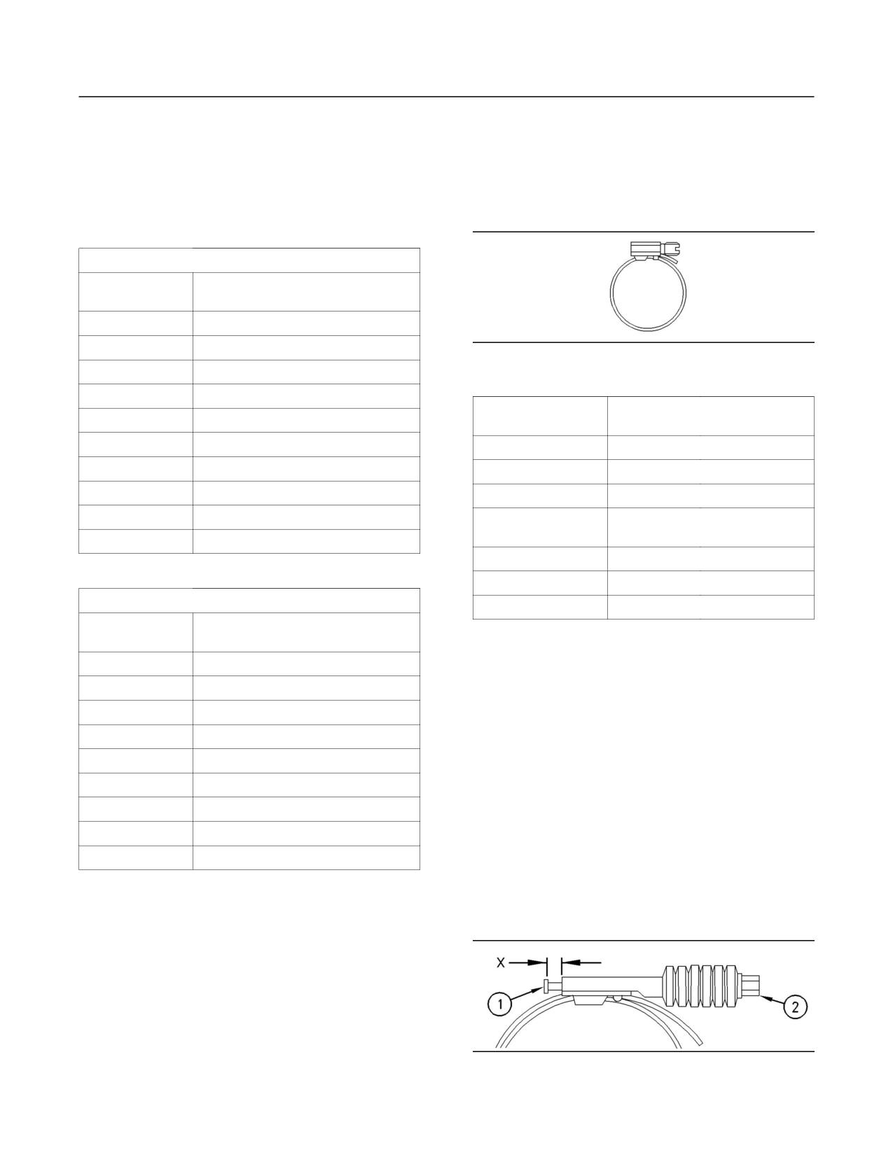
35
Maintenance Section
Torque Specifications
i00621350
i01206505
Standard Torque for Metric
Standard Torque for Worm
Fasteners
Drive Band Hose Clamps
SMCS Code: 7553
SMCS Code: 7553; 7554
Table 5
Metric Nuts and Bolts
Thread Size
Standard Torque
Metric
M6
12 ± 3 N·m (9 ± 2 lb ft)
M8
28 ± 7 N·m (21 ± 5 lb ft)
g00280501
Illustration 25
M10
55 ± 10 N·m (41 ± 7 lb ft)
Table 7
M12
100 ± 20 N·m (75 ± 15 lb ft)
Initial Installation Torque
Width of Clamp
M14
160 ± 30 N·m (120 ± 22 lb ft)
On New Hose
M16
240 ± 40 N·m (175 ± 30 lb ft)
7.9 mm (0.31 inch)
0.9 ± 0.2 N·m (8 ± 2 lb in)
M20
460 ± 60 N·m (340 ± 44 lb ft)
13.5 mm (0.53 inch)
4.5 ± 0.5 N·m (40 ± 4 lb in)
M24
800 ± 100 N·m (590 ± 75 lb ft)
15.9 mm (0.63 inch)
7.5 ± 0.5 N·m (65 ± 4 lb in)
M30
1600 ± 200 N·m (1180 ± 150 lb ft)
Reassembly or Retightening
Width of Clamp
Torque
M36
2700 ± 300 N·m (2000 ± 220 lb ft)
7.9 mm (0.31 inch)
0.7 ± 0.2 N·m (6 ± 2 lb in)
Table 6
13.5 mm (0.53 inch)
3.0 ± 0.5 N·m (27 ± 4 lb in)
Metric Taperlock Studs
15.9 mm (0.63 inch)
4.5 ± 0.5 N·m (40 ± 4 lb in)
Thread Size
Standard Torque
Metric
i01206414
M6
8 ± 3 N·m (6 ± 2 lb ft)
Standard Torque for Constant
M8
17 ± 5 N·m (13 ± 4 lb ft)
M10
35 ± 5 N·m (26 ± 4 lb ft)
Torque Hose Clamps
M12
65 ± 10 N·m (48 ± 7 lb ft)
SMCS Code: 7553; 7554
M16
110 ± 20 N·m (80 ± 15 lb ft)
Use a constant torque hose clamp in place of any
M20
170 ± 30 N·m (125 ± 22 lb ft)
standard hose clamp. Ensure that the constant
torque hose clamp is the same size as the standard
M24
400 ± 60 N·m (300 ± 44 lb ft)
hose clamp. Due to extreme temperature changes,
M30
750 ± 80 N·m (550 ± 60 lb ft)
the hose will heat set. Heat setting can cause hose
clamps to loosen. Loose hose clamps can result
M36
1200 ± 150 N·m (880 ± 110 lb ft)
in leaks. There have been reports of component
failures that have been caused by hose clamps that
have loosened. The constant torque hose clamp will
help prevent these failures.
g00279591
Illustration 26
36
Maintenance Section
Torque Specifications
Use a torque wrench for proper installation of the
constant torque hose clamps. The constant torque
hose clamp is installed correctly under the following
conditions:
• Screw tip (1) extends 6.35 mm (0.25 inch) (X)
beyond the housing.
• The belleville washers are collapsed nearly
flat after screw (2) is tightened to a torque of
11 ± 1 N·m (98 ± 9 lb in).
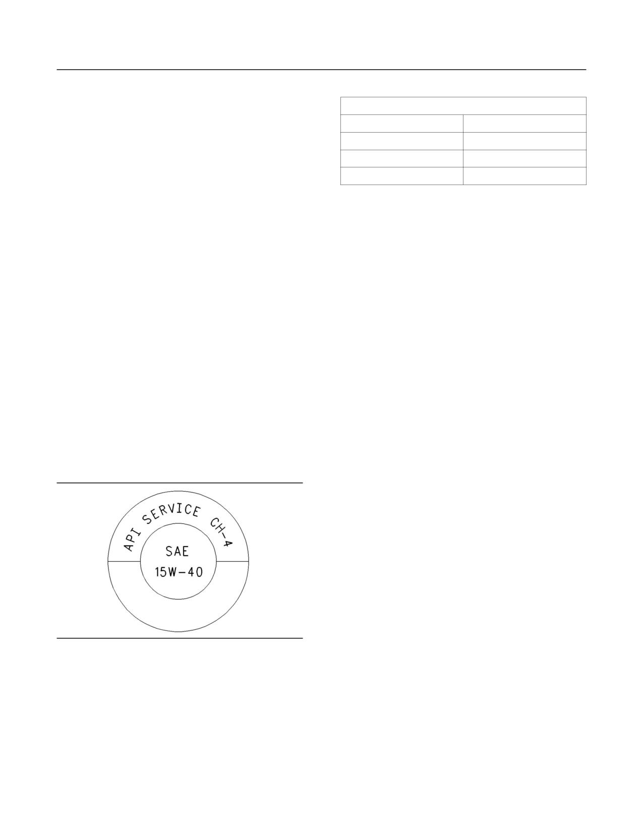
37
Maintenance Section
Lubricant Specifications
Table 8
Lubricant Specifications
API Classifications
i01111306
Current
Obsolete
CF-4, CG-4, CH-4
CE
Lubricant Information
CF
CC, CD
SMCS Code: 1000; 1300; 7581
CF-2(1)
CD-2(1)
(1) CD-2 and API CF-2 are classifications for two-cycle diesel
General Information
engines. Caterpillar does not sell engines that utilize CD-2 and
API CF-2 oils.
Because of government regulations regarding
the certification of engine exhaust emissions, the
Note: API CF is not the same classification as
lubricant recommendations must be followed.
API CF-4. API CF oils are only recommended
for Caterpillar 3600 Series Diesel Engines and
Caterpillar engines with precombustion chamber
Engine Manufacturers Association
(PC) fuel systems.
(EMA) Oils
Grease
The “Engine Manufacturers Association
Recommended Guideline on Diesel Engine Oil” is
The classifications of grease are based on the
recognized by Caterpillar. For detailed information
“ASTM D217” worked penetration characteristics.
about this guideline, see the latest edition of EMA
These characteristics for grease are given a defined
publication, “EMA LRG-1”.
consistency number.
API Oils
Terminology
The Engine Oil Licensing and Certification System
Certain abbreviations follow the nomenclature of
by the American Petroleum Institute (API) is
“SAE J754”. Some classifications follow “SAE J183”
recognized by Caterpillar. For detailed information
abbreviations, and some classifications follow the
about this system, see the latest edition of the “API
“EMA Recommended Guideline on Diesel Engine
publication No. 1509”. Engine oils that bear the API
Oil”. In addition to Caterpillar definitions, there
symbol are authorized by API.
are other definitions that will be of assistance in
purchasing lubricants. Recommended oil viscosities
can be found in this publication, “Engine Oil” topic
(Maintenance Section).
i01261682
Engine Oil
SMCS Code: 1300; 1348; 7581
Caterpillar Diesel Engine Oil
Caterpillar Oils have been developed and tested in
order to provide the full performance and service
g00546535
Illustration 27
life that has been designed and built into Caterpillar
Typical API symbol
Engines. Caterpillar Oils are currently used to fill
diesel engines at the factory. These oils are offered
Diesel engine oils CC, CD, CD-2, and CE have
by Caterpillar dealers for continued use when the
not been API authorized classifications since 1
engine oil is changed. Consult your Caterpillar
January 1996. Table 8 summarizes the status of the
dealer for more information on these oils.
classifications.
Due to significant variations in the quality and in
the performance of commercially available oils,
Caterpillar makes the following recommendations:
• Caterpillar Diesel Engine Oil (10W30)
38
Maintenance Section
Lubricant Specifications
• Caterpillar Diesel Engine Oil (15W40)
EMA LRG-1 - The Engine Manufacturers
Association (EMA) has developed lubricant
Caterpillar multigrade Diesel Engine Oil is
recommendations as an alternative to the API oil
formulated with the correct amounts of detergents,
classification system. LRG-1 is a Recommended
dispersants, and alkalinity in order to provide
Guideline that defines a level of oil performance
superior performance in Caterpillar Diesel Engines.
for these types of diesel engines: high speed, four
stroke cycle, heavy-duty, and light duty. LRG-1
Caterpillar multigrade Diesel Engine Oil is available
oils may be used in Caterpillar engines when the
in two viscosity grades (10W30 and 15W40).
following oils are recommended: API CH-4, API
For direct injection engines, see Table 9 in order
CG-4, and API CF-4. LRG-1 oils are intended to
to choose the correct viscosity grade for the
provide superior performance in comparison to API
ambient temperature. Multigrade oils provide the
CG-4 and API CF-4.
correct viscosity for a broad range of operating
temperatures.
LRG-1 oils will meet the needs of high performance
Caterpillar diesel engines that are operating in
Multigrade oils are effective in maintaining low oil
many applications. The tests and the test limits that
consumption and low levels of piston deposits.
are used to define LRG-1 are similar to the new
API CH-4 classification. Therefore, these oils will
Caterpillar multigrade Diesel Engine Oil can be
also meet the requirements of the low emissions
used in other diesel engines and in gasoline
diesel engines. LRG-1 oils are designed to control
engines. See the engine manufacturer’s guide for
the harmful effects of soot with improved wear
the recommended specifications. Compare the
resistance and improved resistance to oil filter
specifications to the specifications of Caterpillar
plugging. These oils will also provide superior piston
multigrade Diesel Engine Oil. The current industry
deposit control for engines with either two-piece
standards for Caterpillar Diesel Engine Oil are listed
steel pistons or aluminum pistons.
on the product label and on the data sheets for the
product.
All LRG-1 oils must complete a full test program
with the base stock and with the viscosity grade of
Consult your Caterpillar dealer for part numbers
the finished commercial oil. The use of “API Base
and for available sizes of containers.
Oil Interchange Guidelines” are not appropriate for
LRG-1 oils. This feature reduces the variation in
performance that can occur when base stocks are
Commercial Oils
changed in commercial oil formulations.
The performance of commercial diesel engine
LRG-1 oils are recommended for use in extended
oils is based on American Petroleum Institute
oil change interval programs that optimize oil life.
(API) classifications. These API classifications are
These oil change interval programs are based
developed in order to provide commercial lubricants
on oil analysis. LRG-1 oils are recommended
for a broad range of diesel engines that operate at
for conditions that demand a premium oil. Your
various conditions.
Caterpillar dealer has the specific guidelines for
optimizing oil change intervals.
If Caterpillar multigrade Diesel Engine Oil is not
used, only use commercial oils that meet the
API CH-4 - API CH-4 oils were developed in
following classifications:
order to meet the requirements of the new high
performance diesel engines. Also, the oil was
• EMA LRG-1 multigrade oil (preferred oil)
designed to meet the requirements of the low
emissions diesel engines. API CH-4 oils are also
• API CH-4 multigrade oil (preferred oil)
acceptable for use in older diesel engines and in
diesel engines that use high sulfur diesel fuel. API
• API CG-4 multigrade oil (preferred oil)
CH-4 oils may be used in Caterpillar engines that
use API CG-4 and API CF-4 oils. API CH-4 oils will
• API CF-4 multigrade oil (acceptable oil)
generally exceed the performance of API CG-4 oils
in the following criteria: deposits on pistons, control
In order to make the proper choice of a commercial
of oil consumption, wear of piston rings, valve train
oil, refer to the following explanations:
wear, viscosity control, and corrosion.
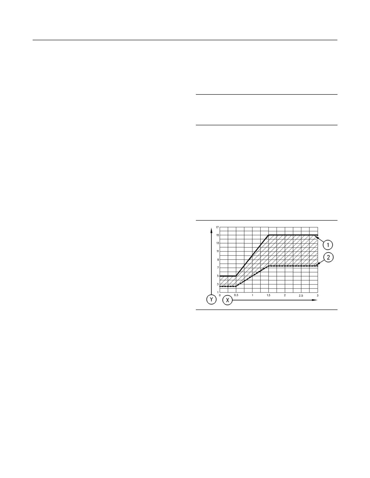
39
Maintenance Section
Lubricant Specifications
Three new engine tests were developed for the
Some commercial oils that meet the API
API CH-4 oil. The first test specifically evaluates
classifications may require reduced oil change
deposits on pistons for engines with the two-piece
intervals. To determine the oil change interval,
steel piston. This test (piston deposit) also measures
closely monitor the condition of the oil and perform a
the control of oil consumption. A second test is
wear metal analysis. Caterpillar’s S·O·S oil analysis
conducted with moderate oil soot. The second
program is the preferred method.
test measures the following criteria: wear of piston
rings, wear of cylinder liners, and resistance to
NOTICE
corrosion. A third new test measures the following
Failure to follow these oil recommendations can cause
characteristics with high levels of soot in the oil:
shortened engine service life due to deposits and/or
wear of the valve train, resistance of the oil in
excessive wear.
plugging the oil filter, and control of sludge.
In addition to the new tests, API CH-4 oils have
Total Base Number (TBN) and Fuel
tougher limits for viscosity control in applications
that generate high soot. The oils also have improved
Sulfur Levels for Direct Injection
oxidation resistance. API CH-4 oils must pass an
(DI) Diesel Engines
additional test (piston deposit) for engines that use
aluminum pistons (single piece). Oil performance is
The Total Base Number (TBN) for an oil depends on
also established for engines that operate in areas
the fuel sulfur level. For direct injection engines that
with high sulfur diesel fuel.
use distillate fuel, the minimum TBN of the new oil
must be 10 times the fuel sulfur level. The TBN is
All of these improvements allow the API CH-4 oil
defined by “ASTM D2896”. The minimum TBN of
to achieve optimum oil change intervals. API CH-4
the oil is 5 regardless of fuel sulfur level. Illustration
oils are recommended for use in extended oil
28 demonstrates the TBN.
change intervals. API CH-4 oils are recommended
for conditions that demand a premium oil. Your
Caterpillar dealer has specific guidelines for
optimizing oil change intervals.
API CG-4 - API CG-4 oils were developed primarily
for diesel engines that use a 0.05 percent level of
fuel sulfur. However, API CG-4 oils can be used
with higher sulfur fuels. The TBN of the new oil
determines the maximum fuel sulfur level for API
CG-4 and API CF-4 oils. See Illustration 28.
API CG-4 oils are the first oils that are required to
pass industry standard tests for foam control and
viscosity shear loss. API CG-4 oils must also pass
g00104890
tests that were developed for corrosion, wear and
Illustration 28
oxidation.
(Y) TBN by “ASTM D2896”
(X) Percentage of fuel sulfur by weight
API CF-4 - These oils service a wide variety of
(1) TBN of new oil
(2) Change the oil when the TBN deteriorates to 50 percent of
modern diesel engines. API CF-4 oils provide more
the original TBN.
stable oil control and reduced piston deposits in
comparison to API CF and the obsolete CE and CD
Use the following guidelines for fuel sulfur levels
classifications of oil. API CF-4 oils provide improved
that exceed 1.5 percent:
soot dispersancy in comparison to API CF and
obsolete CD oils. The API CF-4 classification was
• Choose an oil with the highest TBN that meets
developed with a 0.40 percent sulfur diesel fuel.
one of these classifications: EMA LRG-1, API
This represents the type of diesel fuels that are
CH-4, API CG-4, and API CF-4.
commonly available worldwide.
• Reduce the oil change interval. Base the oil
Note: Do not use single grade API CF oils or
change interval on the oil analysis. Ensure that
multigrade API CF oils in Caterpillar Direct Injection
the oil analysis includes the condition of the oil
(DI) Commercial Diesel Engines.
and a wear metal analysis.

40
Maintenance Section
Lubricant Specifications
Excessive piston deposits can be produced by an
i01111406
oil with a high TBN. These deposits can lead to a
Synthetic Base Stock Oils
loss of control of the oil consumption and to the
polishing of the cylinder bore.
SMCS Code: 1300; 1348; 7581
NOTICE
Synthetic base oils are acceptable for use
Operating Direct Injection (DI) diesel engines with fuel
in Caterpillar engines if these oils meet the
sulfur levels over 1.0 percent may require shortened
performance requirements that are specified for the
oil change intervals in order to help maintain adequate
engine compartment.
wear protection.
Synthetic base oils generally perform better than
conventional oils in the following two areas:
Lubricant Viscosity Recommendations
for Direct Injection (DI) Diesel Engines
• Synthetic base oils have improved flow at low
temperatures especially in arctic conditions.
The proper SAE viscosity grade of oil is determined
by the minimum ambient temperature during
• Synthetic base oils have improved oxidation
cold engine start-up, and the maximum ambient
stability especially at high operating temperatures.
temperature during engine operation.
Some synthetic base oils have performance
Refer to Table 9 (minimum temperature) in order
characteristics that enhance the service life of the
to determine the required oil viscosity for starting
oil. However, Caterpillar does not recommend the
a cold engine.
automatic extension of oil change intervals for
any type of oil. Oil change intervals for Caterpillar
Refer to Table 9 (maximum temperature) in order to
engines can only be adjusted after an oil analysis
select the oil viscosity for engine operation at the
program that contains the following tests: oil
highest ambient temperature that is anticipated.
condition and wear metal analysis (Caterpillar’s
S·O·S oil analysis), trend analysis, fuel consumption,
Generally, use the highest oil viscosity that
and oil consumption.
is available to meet the requirement for the
temperature at start-up.
i01111412
Table 9
Re-refined Base Stock Oils
Engine Oil Viscosity
Caterpillar DEO
Ambient Temperature
SMCS Code: 1300; 7581
Multigrade
EMA LRG-1
Re-refined base stock oils are acceptable for
API CH-4
use in Caterpillar engines if these oils meet the
API CG-4 and
Minimum
Maximum
performance requirements that are specified by
API CF-4
Caterpillar. Re-refined base stock oils can be used
Viscosity Grade
exclusively in finished oil or in a combination with
SAE 0W20
-40 C (-40 F)
10
C (50 F)
new base stock oils. The US military specifications
and the specifications of other heavy equipment
SAE 0W30
-40 C (-40 F)
30
C (86 F)
manufacturers also allow the use of re-refined base
stock oils that meet the same criteria.
SAE 0W40
-40 C (-40 F)
40 C (104 F)
SAE 5W30
-30 C (-22 F)
30
C (86 F)
The process that is used to make re-refined base
stock oil should adequately remove all wear metals
SAE 5W40
-30 C (-22 F)
40 C (104 F)
that are in the used oil and all additives that are
SAE 10W30
-20 C (-4 F)
40 C (104 F)
in the used oil. The process that is used to make
re-refined base stock oil generally involves the
SAE 15W40
-15 C (5 F)
50 C (122 F)
processes of vacuum distillation and hydrotreating
the used oil. Filtering is inadequate for the
production of high quality re-refined base stock oils
from used oil.
41
Maintenance Section
Lubricant Specifications
i01113213
i01123104
Cold Weather Lubricants
Aftermarket Oil Additives
SMCS Code: 1300; 1348; 7581
SMCS Code: 1300; 1348; 7581
When an engine is started and an engine is
Caterpillar does not recommend the use of
operated in ambient temperatures below -20 C
aftermarket additives in oil. It is not necessary to
(-4
F), use multigrade oils that are capable of
use aftermarket additives in order to achieve the
flowing in low temperatures.
engine’s maximum service life or rated performance.
Fully formulated, finished oils consist of base oils
These oils have lubricant viscosity grades of SAE
and of commercial additive packages. These
0W or SAE 5W.
additive packages are blended into the base oils
at precise percentages in order to help provide
When an engine is started and operated in ambient
finished oils with performance characteristics that
temperatures below -30 C (-22 F), use a synthetic
meet industry standards.
base stock multigrade oil with a 0W viscosity grade
or with a 5W viscosity grade. Use an oil with a pour
There are no industry standard tests that evaluate
point that is lower than -50 C (-58 F).
the performance or the compatibility of aftermarket
additives in finished oil. Aftermarket additives may
The number of acceptable lubricants is limited in
not be compatible with the finished oil’s additive
cold weather conditions. Caterpillar recommends
package, which could lower the performance of the
the following lubricants for use in cold weather
finished oil. The aftermarket additive could fail to
conditions:
mix with the finished oil. This could produce sludge
in the crankcase. Caterpillar discourages the use of
First Choice - use an oil with an EMA LRG-1
aftermarket additives in finished oils.
Recommended Guideline or use a CH-4 oil that is
API licensed with an SAE 0W20, SAE 0W30, SAE
To achieve the best performance from a Caterpillar
0W40, SAE 5W30, or SAE 5W40 lubricant viscosity
engine, conform to the following guidelines:
grade. A CG-4 oil that is API licensed with an SAE
0W20, SAE 0W30, SAE 0W40, SAE 5W30, or SAE
• Select the proper Caterpillar oil or a commercial
5W40 lubricant viscosity grade may also be used.
oil that meets the “EMA Recommended Guideline
A CF-4 oil that is API licensed with an SAE 0W20,
on Diesel Engine Oil” or the recommended API
SAE 0W30, SAE 0W40, SAE 5W30, or SAE 5W40
classification.
lubricant viscosity grade may also be used.
•
See the appropriate “Lubricant Viscosities” table
Second Choice - use an oil that contains the CH-4,
in order to find the correct oil viscosity grade for
CG-4, or CF-4 additive package although the oil
your engine.
has not been tested for the requirements of the
API license. The oil must have an SAE 0W20,
• At the specified interval, service the engine
SAE 0W30, SAE 0W40, SAE 5W30, or SAE 5W40
compartment. Use new oil and install a new oil
lubricant viscosity grade.
filter.
• Perform maintenance at the intervals that are
NOTICE
specified in the Operation and Maintenance
Shortened engine service life could result if second
Manual, “Maintenance Interval Schedule”.
choice oils are used.
i01164576
Lubricating Grease
SMCS Code: 7581
Caterpillar provides greases in order to cover a
variety of applications and extreme temperature
conditions. Consult your Caterpillar dealer for part
numbers and for available sizes of containers.
42
Maintenance Section
Lubricant Specifications
Note: Some greases may not be used with other
• Increased retention
greases. When a commercial grease is used,
ensure that the grease is compatible with the
• Resistance to heavy loads
grease that is currently used in the system. If the
commercial grease is not compatible, the system
This product is recommended for heavily loaded pin
must be purged. If any questions arise concerning
joints and for journal bearings. This product meets
the compatibility of a grease, consult the supplier.
the certification of “GC-LB”. Normal operating
temperatures for this product are -28 to 149 C
(-18 to 300 F) for the NLGI No. 0. Normal operating
Multipurpose Greases
temperatures for this product are -18 to 149 C
(0 to 300 F) for the NLGI No. 2.
Multipurpose Lithium Complex Grease
(MPGL)
Note: If MPGM is not available, use a multipurpose
type grease which contains three to five percent
Multipurpose Lithium Complex Grease (MPGL)
molybdenum.
is a general purpose lithium complex grease for
medium-duty applications. This product has good
Special Purpose Grease (SPG)
characteristics at high temperatures such as a
dropping point of 260 C (500 F). MPGL contains
Bearing Lubrication (SPG)
unleaded extreme pressure additives, antiwear
inhibitors, and corrosion inhibitors that provide extra
Bearing Lubricant (SPG) is available in a NLGI
protection in the following applications:
No. 2 grade with a polyurea thickener. This
grease is recommended for high temperature
• Construction
antifriction bearings in the following applications:
electric starting motors, alternators, fan drives,
• Agricultural
and generators. The Bearing Lubricant (SPG) has
an effective operating range of -29 to 177 C
• Automotive
(-20 to 350 F).
MPGL meets the requirements for extended service
intervals of automotive chassis points. MPGL also
Water and Temperature Resistant Grease
meets the requirements for extended service
(WTR)
intervals of wheel bearings with disc brakes in
automobiles, in vans and in light trucks. This
The Water and Temperature Resistant Grease is
product meets the NLGI certification of “GC-LB”.
designed for use whenever the following conditions
MPGL is also available in a NLGI No. 2 grade.
are a concern: water washout, severe corrosion,
Normal operating temperatures for this product are
and high operating temperatures. The Water and
-28 to 149 C (-18 to 300 F). This product is also
Temperature Resistant Grease provides extreme
available as a white lithium complex grease.
pressure protection, antiwear protection, rust
protection and corrosion protection. The Water and
Multipurpose Lithium Complex Grease
Temperature Resistant Grease is an environmentally
friendly grease which does not contain the following
with Molybdenum (MPGM)
materials: antimony, sulfur, barium, zinc, lead, and
phosphorous materials. The Water and Temperature
Multipurpose Lithium Complex Grease with
Resistant Grease has excellent shear stability. Water
Molybdenum (MPGM) is a general purpose
and Temperature Resistant Grease can also resist
lithium complex grease that is used for light-duty
breakdown in the presence of water. The Water
applications and for medium-duty applications. The
and Temperature Resistant Grease works well in
MPGM is available in the following grades: NLGI
the following applications:
No. 2 and NLGI No. 0. The MPGM is strengthened
with a molybdenum disulfide and a polymer for
extra lubrication and protection. MPGM contains
• Construction
unleaded additives. MPGM also contains antiwear
inhibitors, rust inhibitors, and corrosion inhibitors
• Agricultural
that are for protection and lubrication in many
environments. The MPGM is formulated with a base
• Automotive
fluid that has high viscosity.
• Industrial
The MPGM has the following features:
• Marine
• Increased protection against water washout
43
Maintenance Section
Lubricant Specifications
This product meets the NLGI certification of
i01065849
“GC-LB”. Normal operating temperatures for this
S·O·S Oil Analysis
product are -40 to 204 C (-40 to 400 F).
SMCS Code: 1348; 7542; 7581
Caterpillar Premium Grease (CPG)
Caterpillar recommends the use of the S·O·S
Desert Gold (CPG)
oil analysis program in order to monitor the
condition and the maintenance requirements of
Desert Gold is a heavy-duty, premium synthetic
the equipment. The S·O·S oil analysis program will
grease that is developed for the most extreme
complement the preventive maintenance program.
operating environments. This grease is formulated
with the following characteristics: high viscosity
The S·O·S oil analysis is a diagnostic tool that is
synthetic base fluid, polymers, molybdenum
used to determine oil performance and component
disulfide, high viscosity index, and high dropping
wear rates. Contamination can be identified and
point.
measured through the use of the S·O·S oil analysis.
The S·O·S oil analysis includes the following tests:
Desert Gold will protect equipment against
heavy shock loads. Desert Gold protects against
• The Wear Rate Analysis monitors the wear of the
corrosion in extreme heat, in moist conditions, or
engine’s metals. The amount of wear metal and
in dusty conditions. This product has excellent
type of wear metal that is in the oil is analyzed.
characteristics of adhesion and of stability.
The increase in the rate of engine wear metal in
Desert Gold provides longer protection than other
the oil is as important as the quantity of engine
greases. Desert Gold is an environmentally friendly
wear metal in the oil. For this reason, regular
grease which does not contain the following
sampling at specified intervals is necessary
materials: antimony, sulfur, barium, zinc, lead,
in order to establish wear rates. Intermittent
and phosphorous materials. Normal operating
sampling does not allow wear rate trend lines
temperatures are -6 to 230 C (21 to 450 F). Desert
to be established. Engine wear metals in the oil
Gold can operate at higher temperatures for short
sample are compared to established Caterpillar
time periods. Desert Gold has additional extreme
norms in order to determine acceptability.
pressure protection for highly loaded pin joints.
Tests are conducted in order to detect
•
contamination of the oil by water, glycol or fuel.
Arctic Platinum (CPG)
Arctic Platinum is a super-premium extreme
• The Oil Condition Analysis determines the loss
of the oil’s lubricating properties. An infrared
pressure lubricating grease that is developed for
analysis is used to compare the properties of
lubrication in temperatures that are below zero to
new oil to the properties of the used oil sample.
moderate operating temperatures. Arctic Platinum
This analysis allows technicians to determine
is available in grades 000, 00, 0, 1, and 2. These
grades ensure pumpability in central lube systems in
the amount of deterioration of the oil during use.
This analysis also allows technicians to verify
a variety of ambient temperatures from -60 to 18 C
the performance of the oil according to the
(-76 to 65 F). Arctic Platinum has a high dropping
specification during the entire oil change interval.
point. Arctic Platinum contains a five percent
concentrate of molybdenum disulfide for protection
The test results of the oil samples will then be used
against extra heavy loads. Arctic Platinum provides
as a basis for determining the oil change interval
excellent corrosion protection and rust protection.
for the engine. The results of the S·O·S oil analysis
Arctic Platinum is an environmentally friendly grease
may allow the engine to operate longer between oil
which does not contain the following materials:
changes without the risk of engine damage.
antimony, sulfur, barium, zinc, and phosphorous.
Table 10
Arctic Platinum is designed for long life lubrication
of the following components: horizontal pivot
S·O·S Oil Analysis Interval
bearings, lower link bearings, steering cylinders,
Compartment
Interval
kingbolt bearings, upper hitch link bearings, and
ejector carrier roller bearings. This grease is extra
Engine crankcase
Every 250 Service Hours
tacky for retention on excavator carbody bearings.
Arctic Platinum has additional extreme pressure
For more information, see Special Publication,
protection for highly loaded pin joints.
PEDP7036, “S·O·S Fluid Analysis”. Consult your
Caterpillar dealer for complete information and
assistance about the program.

44
Maintenance Section
Fuel Specifications
(Table 11, contd)
Fuel Specifications
Caterpillar Specifications for Distillate Diesel Fuel
Specifications
Requirements
ASTM
i01196007
Test
Fuel Recommendations
10% at 282 C (540 F)
“D86”
maximum
SMCS Code: 1250; 1280
Distillation
90% at 360 C (680 F)
Diesel engines have the ability to burn a wide
maximum
variety of fuels. These fuels are divided into two
Flash Point
legal limit
“D93”
general groups. The two groups are called the
preferred fuels and the permissible fuels.
30 minimum
“D287”
API Gravity
45 maximum
The preferred fuels provide maximum engine
service life and performance. The preferred fuels
6
C (10 F) minimum
“D97”
are distillate fuels. These fuels are commonly called
Pour Point
below ambient
temperature
diesel fuel, furnace fuel, gas oil, or kerosene.
3% maximum
“D3605”
The permissible fuels are crude oils or blended
Sulfur(1)
or
fuels. Use of these fuels can result in higher
“D1552”
maintenance costs and in reduced engine service
1.4 cSt minimum and 20.0
“D445”
life.
Kinematic
cSt maximum at 40 C
Viscosity(2)
(104
F)
Diesel fuels that meet the specifications in Table 11
will help to provide maximum engine service life
Water and
0.1% maximum
“D1796”
and performance. In North America, diesel fuel that
Sediment
is identified as No. 1-D or No. 2-D in “ASTM D975”
Water
0.1% maximum
“D1744”
generally meet the specifications. Table 11 is for
diesel fuels that are distilled from crude oil. Diesel
Sediment
0.05% maximum (weight)
“D473”
fuels from other sources could exhibit detrimental
Gums and
10 mg per 100 mL
“D381”
properties that are not defined or controlled by this
Resins(3)
maximum
specification.
3100 g minimum
“D6078”
Table 11
0.45 mm (0.018 inch)
Caterpillar Specifications for Distillate Diesel Fuel
maximum at 60 C
Lubricity(4)
(140
F)
“D6079”
Specifications
Requirements
ASTM
Test
0.38 mm (0.015 inch)
maximum at 25 C (77 F)
Aromatics
35% maximum
“D1319”
(1) Caterpillar fuel systems and engine components can
Ash
0.02% maximum (weight)
“D482”
operate on high sulfur fuels. Fuel sulfur levels affect exhaust
emissions. High sulfur fuels also increase the potential for
Carbon
0.35% maximum (weight)
“D524”
corrosion of internal components. Fuel sulfur levels above 1.0
Residue on
percent may significantly shorten the oil change interval. For
10% Bottoms
additional information, see this publication, “Engine Oil” topic
(Maintenance Section).
40 minimum (DI engines)
“D613”
(2) The values of the fuel viscosity are the values as the fuel
Cetane Number
is delivered to the fuel injection pumps. If a fuel with a low
35 minimum (PC engines)
viscosity is used, cooling of the fuel may be required to maintain
-
a 1.4 cSt viscosity at the fuel injection pump. Fuels with a high
The cloud point must
viscosity might require fuel heaters in order to bring down the
not exceed the lowest
Cloud Point
viscosity to a 20 cSt viscosity. For additional information, see
expected ambient
Special Publication, SEBD0717, “Diesel Fuel and Your Engine”.
temperature.
(3) Follow the test conditions and procedures for gasoline (motor).
(4) The lubricity of a fuel is a concern with low sulfur fuel. To
Copper Strip
No. 3 maximum
“D130”
determine the lubricity of the fuel, use either the “ASTM D6078
Corrosion
Scuffing Load Wear Test (SBOCLE)” or the “ASTM D6079 High
(continued)
Frequency Reciprocating Rig (HFRR)” test. If the lubricity of a
fuel does not meet the minimum requirements, consult your
fuel supplier. Do not treat the fuel without consulting the fuel
supplier. Some additives are not compatible. These additives
can cause problems in the fuel system.
45
Maintenance Section
Fuel Specifications
There are many other diesel fuel specifications that
NOTICE
are published by governments and by technological
Operating with fuels that do not meet Caterpillar’s rec-
societies. Usually, those specifications do not
ommendations can cause the following effects: start-
review all the requirements that are addressed
ing difficulty, poor combustion, deposits in the fuel in-
in this specification. To ensure optimum engine
jectors, reduced service life of the fuel system, de-
performance, a complete fuel analysis should be
posits in the combustion chamber, and reduced ser-
obtained before engine operation. The fuel analysis
vice life of the engine.
should include all of the properties that are listed
in Table 11.
In the USA, 0.05 percent diesel fuels have been
used in all on-highway truck engines since 1
January 1994. This low sulfur diesel fuel was
mandated as a means of directly reducing
particulate emissions from diesel truck engines.
This low sulfur fuel will also be used in Caterpillar
commercial diesel engines when low emissions are
required or when the fuel supply sources provide
this type of fuel. Caterpillar has not seen any
detrimental effects with 0.05 percent sulfur fuel in
Caterpillar diesel engines.
NOTICE
Heavy Fuel Oil (HFO), Residual fuel, or Blended fuel
must NOT be used in Caterpillar diesel engines (ex-
cept in 3600 Series HFO engines). Severe component
wear and component failures will result if HFO type fu-
els are used in engines that are configured to use dis-
tillate fuel.
In extreme cold ambient conditions, you may
use the distillate fuels that are specified in Table
12. However, the fuel that is selected must meet
the requirements that are specified in Table 11.
These fuels are intended to be used in operating
temperatures that are down to -54 C (-65 F).
Table 12
Distillate Fuels(1)
Specification
Grade
“MIL-T-5624R”
JP-5
“ASTM D1655”
Jet-A-1
“MIL-T-83133D”
JP-8
(1) The fuels that are listed in this Table may not meet the
requirements that are specified in the “Caterpillar Specifications
for Distillate Diesel Fuel” Table. Consult the supplier for the
recommended additives in order to maintain the proper fuel
lubricity.
These fuels are lighter than the No. 2 grades of fuel.
The cetane number of the fuels in Table 12 must be
at least 40. If the viscosity is below 1.4 cSt at 38 C
(100
F), use the fuel only in temperatures below
0 C (32 F). Do not use any fuels with a viscosity
of less than 1.2 cSt at 38 C (100 F). Fuel cooling
may be required in order to maintain the minimum
viscosity of 1.4 cSt at the fuel injection pump.
46
Maintenance Section
Cooling System Specifications
Many engine failures are related to the cooling
Cooling System
system. The following problems are related to
Specifications
cooling system failures: overheating, leakage of the
water pump, plugged radiators or heat exchangers,
and pitting of the cylinder liners.
i01261719
These failures can be avoided with proper cooling
General Coolant Information
system maintenance. Cooling system maintenance
is as important as maintenance of the fuel system
SMCS Code: 1350; 1395
and the lubrication system. Quality of the coolant
is as important as the quality of the fuel and the
NOTICE
lubricating oil.
Never add coolant to an overheated engine. Engine
damage could result. Allow the engine to cool first.
Coolant is normally composed of three elements:
water, additives, and glycol.
NOTICE
Water
If the engine is to be stored in, or shipped to an area
with below freezing temperatures, the cooling system
must be either protected to the lowest outside temper-
NOTICE
ature or drained completely to prevent damage.
All Caterpillar diesel engines equipped with air-to-air
aftercooling (ATAAC) require a minimum of 30 percent
glycol to prevent water pump cavitation.
NOTICE
In cold weather, frequently check the specific gravity
of the coolant solution to ensure adequate protection.
NOTICE
Never use water alone without Supplemental Coolant
Additives (SCA) or without inhibited coolant. Water
Clean the cooling system for the following reasons:
alone is corrosive at engine operating temperatures.
Water alone does not provide adequate protection
• Contamination of the cooling system
against boiling or freezing.
• Overheating of the engine
Water is used in the cooling system in order to
transfer heat.
• Foaming of the coolant
Note: Air pockets can form in the cooling system if
Distilled water or deionized water is
the cooling system is filled at a rate that is greater
recommended for use in engine cooling systems.
than 20 L (5 US gal) per minute.
DO NOT use the following types of water in cooling
After you drain the cooling system and after you
systems: hard water, softened water that has been
refill the cooling system, operate the engine.
conditioned with salt, and sea water.
Operate the engine without the filler cap until the
coolant reaches normal operating temperature and
If distilled water or deionized water is not available,
the coolant level stabilizes. Ensure that the coolant
use water with the properties that are listed in Table
is maintained to the proper level.
13.
NOTICE
Never operate an engine without water temperature
regulators in the cooling system. Water temperature
regulators help to maintain the engine coolant at the
proper operating temperature. Cooling system prob-
lems can develop without water temperature regula-
tors.
Refer to Special Instruction, SEBD0518, “Know
Your Cooling System” and Special Instruction,
SEBD0970, “Coolant and Your Engine” for more
detailed information.

47
Maintenance Section
Cooling System Specifications
Table 13
• Formation of gel compounds
Caterpillar Minimum Acceptable Water Requirements
• Reduction of heat transfer
Property
Maximum Limit
ASTM Test
• Leakage of the water pump seal
40 mg/L
“D512”,
Chloride (Cl)
(2.4 grains/US gal)
“D4327”
• Plugging of radiators, coolers, and small
100 mg/L
passages
Sulfate (SO4)
“D516”
(5.9 grains/US gal)
170 mg/L
Glycol
Total Hardness
“D1126”
(10 grains/US gal)
Glycol in the coolant helps to provide protection
340 mg/L
Total Solids
“D1888”
(20 grain/US gal)
against the following conditions:
Acidity
pH of 5.5 to 9.0
“D1293”
• Boiling
For a water analysis, consult one of the following
• Freezing
sources:
• Cavitation of the water pump and the cylinder liner
• Caterpillar dealer
For optimum performance, Caterpillar recommends
a 1:1 mixture of a water/glycol solution.
• Local water utility company
• Agricultural agent
NOTICE
All Caterpillar diesel engines equipped with air-to-air
• Independent laboratory
aftercooling (ATAAC) require a minimum of 30 percent
glycol to prevent water pump cavitation.
Additives
Note: Use a mixture that will provide protection
Additives help to protect the metal surfaces of
against the lowest ambient temperature.
the cooling system. A lack of coolant additives
or insufficient amounts of additives enable the
Note: 100 percent pure glycol will freeze at a
following conditions to occur:
temperature of -23 C (-9 F).
• Corrosion
Most conventional heavy-duty coolant/antifreezes
use ethylene glycol. Propylene glycol may also be
• Formation of mineral deposits
used. In a 1:1 mixture with water, ethylene and
propylene glycol provide similar protection against
• Rust
freezing and boiling. See Tables 14 and 15.
• Scale
Table 14
Ethylene Glycol
• Pitting and erosion from cavitation of the cylinder
liner
Freeze
Boil
Concentration
Protection
Protection
• Foaming of the coolant
50 Percent
-36 C (-33 F)
106 C (223 F)
Many additives are depleted during engine
60 Percent
-51 C (-60 F)
111 C (232 F)
operation. These additives must be replaced
periodically. This can be done by adding
Supplemental Coolant Additives (SCA) to Diesel
NOTICE
Engine Antifreeze/Coolant (DEAC) or by adding
Do not use propylene glycol in concentrations that ex-
ELC Extender to Extended Life Coolant (ELC).
ceed 50 percent glycol because of propylene glycol’s
reduced heat transfer capability. Use ethylene glycol
Additives must be added at the proper
in conditions that require additional protection against
concentration. Overconcentration of additives can
boiling or freezing.
cause the inhibitors to drop out-of-solution. The
deposits can enable the following problems to
occur:
48
Maintenance Section
Cooling System Specifications
Table 15
NOTICE
Propylene Glycol
All Caterpillar diesel engines equipped with air-to-air
Freeze
Boil
Concentration
aftercooling (ATAAC) require a minimum of 30 percent
Protection
Protection
glycol to prevent water pump cavitation.
50 Percent
-29 C (-20 F)
106 C (223 F)
Table 16
To check the concentration of glycol, use the
Coolant Service Life
1U-7298 Coolant/Battery Tester (Degree Celsius)
Coolant Type
Service Life
or use the 1U-7297 Coolant/Battery Tester (Degree
Fahrenheit). The testers give readings that are
6000 Service Hours or
Caterpillar ELC
immediate and accurate. The testers can be used
Six Years
with ethylene or propylene glycol.
3000 Service Hours or
Caterpillar DEAC
Three Years
i01096597
Commercial Heavy-Duty
3000 Service Hours or
Coolant/Antifreeze that
Coolant Recommendations
Two Years
meets “ASTM D5345”
SMCS Code: 1350; 1395
Commercial Heavy-Duty
3000 Service Hours or
Coolant/Antifreeze that
One Year
The following two coolants are used in Caterpillar
meets “ASTM D4985”
diesel engines:
Caterpillar SCA and
3000 Service Hours or
Water
Two Years
Preferred - Caterpillar Extended Life Coolant (ELC)
Commercial SCA and
3000 Service Hours or
or a commercial extended life coolant that meets
Water
One Year
the Caterpillar EC-1 specification
Acceptable - A Caterpillar Diesel Engine
Antifreeze/Coolant (DEAC) or a commercial
i01200209
heavy-duty coolant/antifreeze that meets “ASTM
S·O·S Coolant Analysis
D4985” or “ASTM D5345” specifications
SMCS Code: 1352; 1395; 7542
NOTICE
Do not use a commercial coolant/antifreeze that only
Testing the engine coolant is important to ensure
meets the ASTM D3306 or D4656 specification. This
that the engine is protected from internal cavitation
type of coolant/antifreeze is made for light duty auto-
and from corrosion. The analysis also tests the
motive applications.
ability of the coolant to protect the engine from
boiling and from freezing. The S·O·S Coolant
Analysis can be done at your Caterpillar dealer.
Caterpillar recommends a 1:1 mixture of water
Caterpillar S·O·S Coolant Analysis is the best
and glycol. This mixture of water and glycol will
way to monitor the condition of your coolant and
provide optimum heavy-duty performance as a
your cooling system. S·O·S Coolant Analysis is a
coolant/antifreeze.
program that is based on periodic samples.
Note: Caterpillar DEAC DOES NOT require a
treatment with an SCA at the initial fill. Commercial
NOTICE
heavy-duty coolant/antifreeze that meets “ASTM
Do not use the same vacuum sampling pump for ex-
D4985” or “ASTM D5345” specifications MAY
tracting oil samples that is used for extracting coolant
require a treatment with an SCA at the initial fill.
samples.
Read the label or the instructions that are provided
by the OEM of the product.
A small residue of either type sample may remain in
the pump and may cause a false positive analysis for
In stationary engine applications and marine engine
the sample being taken.
applications that do not require anti-boil protection
or freeze protection, a mixture of SCA and water is
Always use a designated pump for oil sampling and a
acceptable. Caterpillar recommends a six percent
designated pump for coolant sampling.
to eight percent concentration of SCA in those
cooling systems. Distilled water or deionized water
Failure to do so may cause a false analysis which
is preferred. Water which has the recommended
could lead to customer and dealer concerns.
properties may be used.
49
Maintenance Section
Cooling System Specifications
New Systems, Refilled Systems,
• Identification of buildup of the impurities that
cause corrosion
and Converted Systems
• Identification of buildup of the impurities that
Perform a coolant analysis (Level 2) at 500 service
cause scaling
hours for new systems, for refilled systems, or for
converted systems that use ELC or use DEAC. This
• Determination of possible electrolysis within the
500 hour check will also check for any residual
engines’ cooling system
cleaner that may have contaminated the system.
The results are reported, and appropriate
Recommended Interval for S·O·S
recommendations are made.
Coolant Sample
For more information on S·O·S Coolant Analysis,
consult your Caterpillar dealer.
Perform a coolant analysis (Level 1) at every 500
service hour interval. Perform a coolant analysis
(Level 2) annually.
i01096605
Note: Check the standard coolant’s Supplemental
Extended Life Coolant (ELC)
Coolant Additive at every oil change.
SMCS Code: 1350; 1395
S·O·S Coolant Analysis (Level 1)
Caterpillar provides Extended Life Coolant (ELC) for
use in the following applications:
A coolant analysis (Level 1) is a test of the
properties of the coolant.
• Heavy-duty spark ignited gas engines
The following properties of the coolant are tested:
• Heavy-duty diesel engines
• Glycol Concentration for freeze protection
• Automotive applications
• Ability to protect from erosion and corrosion
The anti-corrosion package for Caterpillar ELC is
different from the anti-corrosion package for other
• pH
coolants. Caterpillar ELC is an ethylene glycol
base coolant. However, Caterpillar ELC contains
• Conductivity
organic corrosion inhibitors and antifoam agents
with low amounts of nitrite. Caterpillar ELC has
• Water hardness
been formulated with the correct amount of these
additives in order to provide superior corrosion
• Visual analysis
protection for all metals in engine cooling systems.
• Odor analysis
ELC extends the service life of the coolant to 6000
service hours or six years. ELC does not require
The results are reported, and appropriate
a frequent addition of a Supplemental Coolant
recommendations are made.
Additive (SCA). An Extender is the only additional
maintenance that is needed at 3000 service hours
S·O·S Coolant Analysis (Level 2)
or one half of the ELC service life.
Level 2 coolant analysis is a comprehensive
ELC is available in a 1:1 premixed cooling solution
chemical evaluation of the coolant. This analysis is
with distilled water. The Premixed ELC provides
also a check of the overall condition of the inside of
freeze protection to -36 C (-33 F). The Premixed
the cooling system.
ELC is recommended for the initial fill of the cooling
system. The Premixed ELC is also recommended
The S·O·S Coolant Analysis has the following five
for topping off the cooling system.
features:
ELC Concentrate is also available. ELC Concentrate
• Full analysis of Level 1
can be used to lower the freezing point to -51 C
(-60 F) for arctic conditions.
• Identification of the source of metal corrosion and
of contaminants
Containers of several sizes are available. Consult
your Caterpillar dealer for the part numbers.

50
Maintenance Section
Cooling System Specifications
Note: Caterpillar developed the EC-1 specification.
Caterpillar ELC Extender
The EC-1 specification is an industry standard. The
EC-1 specification defines all of the performance
Caterpillar ELC Extender is added to the cooling
requirements that are needed for an engine coolant
system halfway through the ELC service life. Treat
to be sold as an extended life coolant for Caterpillar
the cooling system with ELC Extender at 3000 hours
engines. ELC can be used in most OEM engines of
or one half of the coolant service life. Use Table 17
the following types: diesel, gasoline, and natural
in order to determine the proper amount of ELC
gas. ELC meets the performance requirements of
Extender that is required.
“ASTM D4985” and “ASTM D5345” for heavy-duty
low silicate antifreeze/coolants. ELC also meets the
Containers of several sizes are available. Consult
performance requirements of “ASTM D3306” and
your Caterpillar dealer for the part numbers.
“ASTM D4656” for automotive applications.
Table 17
Caterpillar ELC Extender Additions by
i01111712
Cooling System Capacity
Extended Life Coolant (ELC)
Addition of ELC
Cooling System Capacity
Extender
Cooling System Maintenance
22 to 30 L (6 to 8 US gal)
0.57 L (20 fl oz)
SMCS Code: 1350; 1352; 1395
31 to 38 L (9 to 10 US gal)
0.71 L (24 fl oz)
Proper additions to the Extended
39 to 49 L (11 to 13 US gal)
0.95 L (32 fl oz)
Life Coolant
50 to 64 L (14 to 17 US gal)
1.18 L (40 fl oz)
65 to 83 L (18 to 22 US gal)
1.60 L (54 fl oz)
NOTICE
84 to 114 L (23 to 30 US gal)
2.15 L (72 fl oz)
Use only Caterpillar products or commercial products
that have passed Caterpillar’s EC-1 specification for
115 to 163 L (31 to 43 US gal)
3.00 L (100 fl oz)
pre-mixed or concentrated coolants.
164 to 242 L (44 to 64 US gal)
4.40 L (148 fl oz)
Use only Caterpillar Extender with Extended Life
Coolant.
For cooling system capacities that exceed the
capacities that are specified in Table 17, use the
Mixing Extended Life Coolant with other products re-
equation that is in Table 18 in order to determine
duces the Extended Life Coolant service life. Failure to
the proper amount of ELC Extender that is required.
follow the recommendations can reduce cooling sys-
tem components life unless appropriate corrective ac-
Table 18
tion is performed.
Equation For Adding ELC Extender To ELC
V × 0.02 = X
In order to maintain the correct balance between
the antifreeze and the additives, you must maintain
V is the total volume of the cooling system.
the recommended concentration of Extended Life
X is the amount of ELC Extender that is required.
Coolant (ELC). Lowering the proportion of antifreeze
lowers the proportion of additive. This will lower
Table 19 is an example for using the equation that
the ability of the coolant to protect the system from
pitting, from cavitation, from erosion, and from
is in Table 18.
deposits.
Table 19
Example Of The Equation For Adding ELC
NOTICE
Extender To ELC
Do not use a conventional coolant to top-off a cooling
system that is filled with Extended Life Coolant (ELC).
Total Volume
Multiplication
Amount of ELC
of the Cooling
Factor
Extender that is
Do not use standard supplemental coolant additive
System (V)
Required (X)
(SCA). Only use ELC Extender in cooling systems that
946 L
× 0.02
19 L
are filled with ELC.
(250 US gal)
(5 US gal)
51
Maintenance Section
Cooling System Specifications
NOTICE
NOTICE
When using Caterpillar ELC, do not use standard
Do not leave an empty SCA filter on an ELC system.
SCA’s or SCA filters. To avoid SCA contamination of
an ELC system, remove the SCA filter base and plug
The filter housing may corrode and leak causing an
off or by-pass the coolant lines.
engine failure.
Remove the SCA filter base and plug off or by-pass
ELC Cooling System Cleaning
the coolant lines.
Note: If the cooling system is already using ELC,
3. Remove the empty SCA filter and remove the
cleaning agents are not required to be used at
filter base. Plug the coolant lines or bypass the
the specified coolant change interval. Cleaning
coolant lines.
agents are only required if the system has been
contaminated by the addition of some other type of
4. Flush the system with clean water in order to
coolant or by cooling system damage.
remove any debris.
Clean water is the only cleaning agent that is
5. Use Caterpillar cleaner to clean the system.
required when ELC is drained from the cooling
Follow the instruction on the label.
system.
6. Drain the cleaner into a suitable container. Flush
ELC can be recycled. The drained coolant mixture
the cooling system with clean water.
can be distilled in order to remove the ethylene
glycol and the water. The ethylene glycol and the
7. Fill the cooling system with clean water and
water can be reused. Consult your Caterpillar dealer
operate the engine until the engine is warmed to
for more information.
49
to 66 C (120 to 150 F).
After the cooling system is drained and after the
NOTICE
cooling system is refilled, operate the engine while
the cooling system filler cap is removed. Operate
Improper or incomplete rinsing of the cooling system
the engine until the coolant level reaches the normal
can result in damage to copper and other metal com-
ponents.
operating temperature and until the coolant level
stabilizes. As needed, add the coolant mixture in
order to fill the system to the proper level.
To avoid damage to the cooling system, make sure
to completely flush the cooling system with clear wa-
ter. Continue to flush the system until all signs of the
Changing to Caterpillar ELC
cleaning agent are gone.
To change from heavy-duty coolant/antifreeze to the
Caterpillar ELC, perform the following steps:
8. Drain the cooling system into a suitable container
and flush the cooling system with clean water.
NOTICE
Note: The cooling system cleaner must be
Care must be taken to ensure that fluids are contained
thoroughly flushed from the cooling system. Cooling
during performance of inspection, maintenance, test-
system cleaner that is left in the system will
ing, adjusting and repair of the product. Be prepared to
contaminate the coolant. The cleaner may also
collect the fluid with suitable containers before open-
corrode the cooling system.
ing any compartment or disassembling any compo-
nent containing fluids.
9. Repeat Steps 7 and 8 until the system is
completely clean.
Refer to Special Publication, NENG2500, “Caterpillar
Tools and Shop Products Guide” for tools and supplies
10. Fill the cooling system with the Caterpillar
suitable to collect and contain fluids on Caterpillar
premixed ELC.
products.
11. Attach the Special Publication, PEEP5027,
Dispose of all fluids according to local regulations and
“Label” to the cooling system filler for the engine
mandates.
in order to indicate the use of Caterpillar ELC.
1. Drain the coolant into a suitable container.
2. Dispose of the coolant according to local
regulations.
52
Maintenance Section
Cooling System Specifications
ELC Cooling System
i01111753
Contamination
Diesel Engine Antifreeze/
Coolant (DEAC)
NOTICE
Mixing ELC with other products reduces the effective-
SMCS Code: 1350; 1395
ness of the ELC and shortens the ELC service life.
Use only Caterpillar products or commercial products
Caterpillar recommends using Caterpillar
that have passed the Caterpillar EC-1 specification for
Diesel Engine Antifreeze/Coolant (DEAC) for
premixed or concentrate coolants. Use only Caterpillar
cooling systems that require a heavy-duty
ELC Extender with Caterpillar ELC. Failure to follow
coolant/antifreeze. Caterpillar DEAC is an alkaline
these recommendations can result in shortened cool-
single-phase ethylene glycol type antifreeze that
ing system component life.
contains corrosion inhibitors and antifoam agents.
ELC cooling systems can withstand contamination
Caterpillar DEAC is formulated with the correct
to a maximum of ten percent of conventional
amount of Caterpillar Supplemental Coolant Additive
heavy-duty coolant/antifreeze or SCA. If the
(SCA). Do no use SCA at the initial fill when DEAC
contamination exceeds ten percent of the total
is used.
system capacity, perform ONE of the following
procedures:
Containers of several sizes are available. Consult
your Caterpillar dealer for the part numbers.
• Drain the cooling system into a suitable container.
Dispose of the coolant according to local
If concentrated DEAC is used, Caterpillar
regulations. Flush the system with clean water. Fill
recommends mixing the concentrate with distilled
the system with the Caterpillar ELC.
water or with deionized water. If distilled water is
not available or deionized water is not available,
• Drain a portion of the cooling system into a
use water which has the required properties. For
suitable container according to local regulations.
the water properties, see this publication, “General
Then, fill the cooling system with premixed ELC.
Coolant Information” topic (Maintenance Section).
This should lower the contamination to less than
10 percent.
i01069295
• Maintain the system as a conventional Diesel
Supplemental Coolant Additive
Engine Antifreeze/Coolant (DEAC). Treat the
system with an SCA. Change the coolant at the
(SCA)
interval that is recommended for the conventional
Diesel Engine Antifreeze/Coolant (DEAC).
SMCS Code: 1350; 1352; 1395
The use of SCA helps to prevent the following
Commercial ELC
conditions from occurring:
If Caterpillar ELC is not used, then select a
• Corrosion
commercial ELC that meets the Caterpillar
specification of EC-1 and either the “ASTM D5345”
• Formation of mineral deposits
specification or the “ASTM D4985” specification. Do
not use an extended life coolant that does not meet
• Cavitation erosion of the cylinder liners
the EC-1 specification. Follow the maintenance
guide for the coolant from the supplier of the
• Foaming of the coolant
commercial ELC. Follow the Caterpillar guidelines
for the quality of water and the specified coolant
Caterpillar Diesel Engine Antifreeze/Coolant (DEAC)
change interval.
is formulated with the correct level of Caterpillar
SCA. When the cooling system is initially filled with
DEAC, adding more SCA is not necessary until the
concentration of SCA has been depleted. To ensure
that the correct amount of SCA is in the cooling
system, the concentration of SCA must be tested
on a scheduled basis. Refer to the specific engine’s
Operation and Maintenance Manual, “Maintenance
Interval Schedule”.
53
Maintenance Section
Cooling System Specifications
Containers of SCA are available in several sizes.
Consult your Caterpillar dealer for the part numbers.
NOTICE
Never use water alone without Supplemental Coolant
Additives (SCA) or without inhibited coolant. Water
i01164588
alone is corrosive at engine operating temperatures.
Commercial Heavy-Duty
Water alone does not provide adequate protection
against boiling or freezing.
Coolant/Antifreeze and SCA
SMCS Code: 1350; 1395
Note: Premix the coolant solution in order to provide
protection to the lowest ambient temperature that
If Caterpillar DEAC is not used, select a
is expected.
coolant/antifreeze with low silicate content for
heavy-duty applications that meets “ASTM D5345”
Note: Pure undiluted antifreeze freezes at -23 C
or “ASTM D4985” specifications.
(-9
F).
Note: When you are not using Caterpillar DEAC the
In engine cooling systems that use water alone,
cooling system must be drained one time during
Caterpillar recommends the use of SCA. SCA helps
every year. The cooling system must be flushed at
to prevent the following conditions from occurring:
this time as well.
• Corrosion
When a heavy-duty coolant/antifreeze is used,
treat the cooling system with three to six
• Formation of mineral deposits
percent Caterpillar SCA by volume. For more
information, see this publication, “Conventional
• Cavitation erosion of the cylinder liner
Coolant/Antifreeze Cooling System Maintenance”
topic (Maintenance Section).
• Foaming of the coolant
If Caterpillar SCA is not used, select a commercial
If Caterpillar SCA is not used, select a commercial
SCA. The commercial SCA must provide a minimum
SCA. The commercial SCA must provide a minimum
of 1200 mg/L or 1200 ppm (70 grains/US gal) of
of 2400 mg/L or 2400 ppm (140 grains/US gal) of
nitrites in the final coolant mixture.
nitrites in the final coolant mixture.
Coolant/antifreeze that meets “ASTM D5345” or
The quality of the water is a very important factor
“ASTM D4985” specifications MAY require treatment
in this type of cooling system. Distilled water
with SCA at the initial fill. These coolants WILL
or deionized water is recommended for use in
require treatment with SCA on a maintenance basis.
cooling systems. If distilled water or deionized
water is not available, use water that meets the
When concentrated coolant/antifreeze is mixed,
minimum requirements that are listed in the table for
Caterpillar recommends mixing the concentrate with
recommended water properties in this publication,
distilled water or with deionized water. If distilled
“General Coolant Information” topic (Maintenance
water or deionized water is not available, water
Section).
which has the required properties may be used. For
the water properties, see this publication, “General
A cooling system that uses a mixture of SCA
Coolant Information” topic (Maintenance Section).
and water only needs more SCA than a cooling
system that uses a mixture of glycol and water. The
SCA concentration in a cooling system that uses
i01318169
SCA and water should be six to eight percent by
volume. Refer to Table 20 for the amount of SCA
Water/Supplemental Coolant
that is required for various capacities of the cooling
Additive (SCA)
system.
SMCS Code: 1350; 1352; 1395
NOTICE
All Caterpillar diesel engines equipped with air-to-air
aftercooling (ATAAC) require a minimum of 30 percent
glycol to prevent water pump cavitation.

54
Maintenance Section
Cooling System Specifications
Table 20
Cooling Systems with Larger
Caterpillar SCA Requirements for SCA and
Capacities
Water Cooling Systems
Cooling System
Caterpillar SCA
Caterpillar SCA
Adding the SCA to Water at the Initial Fill
Capacity
at Initial Fill
at 250 Hours
Use the equation that is in Table 22 to determine
22 to 30 L
1.75 L (64 fl oz)
0.44 L (15 fl oz)
the amount of Caterpillar SCA that is required at
(6 to 8 US gal)
the initial fill. This equation is for a mixture of only
31 to 38 L
SCA and water.
2.30 L (80 fl oz)
0.57 L (20 fl oz)
(9 to 10 US gal)
Table 22
39 to 49 L
3.00 L (100 fl oz)
0.75 L (25 fl oz)
(11 to 13 US gal)
Equation For Adding The SCA To Water
At The Initial Fill
50 to 64 L
3.90 L (128 fl oz)
0.95 L (32 fl oz)
(14 to 17 US gal)
V × 0.07 = X
65 to 83 L
V is the total volume of the cooling system.
5.00 L (168 fl oz)
1.25 L (42 fl oz)
(18 to 22 US gal)
X is the amount of SCA that is required.
84 to 110 L
6.60 L (224 fl oz)
1.65 L (56 fl oz)
(23 to 29 US gal)
Table 23 is an example for using the equation that
111 to 145 L
is in Table 22.
8.75 L (296 fl oz)
2.19 L (74 fl oz)
(30 to 38 US gal)
Table 23
146 to 190 L
11.50 L
2.88 L (98 fl oz)
(39 to 50 US gal)
(392 fl oz)
Example Of The Equation For Adding The SCA
To Water At The Initial Fill
191 to 250 L
15.00 L
3.75 L (128 fl oz)
(51 to 66 US gal)
(512 fl oz)
Total Volume
Multiplication
Amount of SCA
of the Cooling
Factor
that is Required
System (V)
(X)
Refer to Table 21 for part numbers and for quantities
of SCA.
946 L
× 0.07
66 L
(250 US gal)
(18 US gal)
Table 21
Caterpillar Liquid SCA
Adding the SCA to Water for Maintenance
Part Number
Quantity
For the recommended service interval, refer to the
6V-3542
0.24 L (8 oz)
Operation and Maintenance Manual, “Maintenance
Interval Schedule” for your engine.
111-2372
0.36 L (12 oz)
8T-1589
0.47 L (16 oz)
Use the 8T-5296 Coolant Conditioner Test Kit to
test the concentration of SCA. Make the following
3P-2044
0.94 L (32 oz)
modifications to Steps 3 and 5 of the 8T-5296
8C-3680
19 L (5 US gal)
Coolant Conditioner Test Kit instructions:
5P-2907
208 L (55 US gal)
STEP 3 - Add tap water to the vial up to the “20
ml” mark.
Maintain the SCA in the same way as you would
maintain a cooling system that uses heavy-duty
STEP 5 - When the defined procedure is used,
coolant/antifreeze. Adjust the maintenance for the
a concentration of six to eight percent will yield
amount of SCA additions. See Table 20 for the
between 20 drops and 27 drops. If the number of
amount of SCA that is required.
drops is below 20 drops, the concentration of SCA
is low. If the number of drops is above 27 drops, the
concentration of SCA is high. Make the appropriate
adjustments to the concentration of SCA.
Test the concentration of SCA or submit a
coolant sample to your Caterpillar dealer. See
this publication, “S·O·S Coolant Analysis” topic
(Maintenance Section).
55
Maintenance Section
Cooling System Specifications
Additions of SCA are based on the results of the
Check the coolant/antifreeze (glycol concentration)
test or based on the results of the coolant analysis.
in order to ensure adequate protection against
The size of the cooling system determines the
boiling or freezing. Caterpillar recommends the
amount of SCA that is required.
use of a refractometer for checking the glycol
concentration. Use the 1U-7298 Coolant/Battery
Use the equation that is in Table 22 to determine
Tester (Celsius) or use the 1U-7297 Coolant/Battery
the amount of Caterpillar SCA that is required for
Tester (Fahrenheit). The testers give readings that
maintenance, if necessary:
are immediate and accurate. The testers can be
used with ethylene or with propylene glycol.
Table 24
SCA To Water Addition Equation For Maintenance
Caterpillar engine cooling systems should be
tested at 250 hour intervals for the concentration of
V × 0.023 = X
Supplemental Coolant Additive (SCA). SCA test kits
V is the total volume of the cooling system.
are available from your Caterpillar dealer. Test the
concentration of SCA or submit a coolant sample to
X is the amount of SCA that is required.
your Caterpillar dealer at 250 hour intervals. Refer
to S·O·S Coolant Analysis for more information on
Table 25 is an example for using the equation that
this topic.
is in Table 22.
Additions of SCA are based on the results of the
Table 25
test or based on the results of the coolant analysis.
An SCA that is liquid or a maintenance element for
SCA To Water Addition Equation Example
an SCA (if equipped) may be needed at 250 hour
For Maintenance
intervals.
Total Volume
Multiplication
Amount of SCA
of the Cooling
Factor
that is Required
Table 26 lists the amount of Caterpillar SCA
System (V)
(X)
that is needed at the initial fill in order to treat
coolant/antifreeze. These amounts of SCA are for
946 L
× 0.023
22 L
(250 US gal)
(6 US gal)
systems that use heavy-duty coolant/antifreeze.
Table 26 also lists additions of SCA for liquid
Note: Specific engine applications may require
and for maintenance elements at 250 hours. The
maintenance practices to be periodically evaluated
additions are required for Caterpillar DEAC and for
in order to properly maintain the engine’s cooling
commercial coolant/antifreezes.
system.
Table 21 lists part numbers and quantities of SCA
that is available from your Caterpillar dealer.
i01111872
Conventional Coolant/
Antifreeze Cooling System
Maintenance
SMCS Code: 1350; 1352; 1395
NOTICE
Never operate an engine without water temperature
regulators in the cooling system. Water temperature
regulators help to maintain the engine coolant at the
proper operating temperature. Cooling system prob-
lems can develop without water temperature regula-
tors.

56
Maintenance Section
Cooling System Specifications
Table 26
Caterpillar SCA Requirements for Heavy-Duty Coolant/Antifreeze
Spin-on
250 Service
Cooling System
Element at 250
Initial Fill(1)
Hour
Capacity
Service Hour
Maintenance(2)
Maintenance(3)
22 to 30 L
0.95 L (32 fl oz)
0.24 L (8 fl oz)
111-2370 (1)
(6 to 8 US gal)
31 to 38 L
1.18 L (40 fl oz)
0.36 L (12 fl oz)
111-2369 (1)
(9 to 10 US gal)
39 to 49 L
1.42 L (48 fl oz)
0.36 L (12 fl oz)
111-2369 (1)
(11 to 13 US gal)
50 to 64 L
1.90 L (64 fl oz)
0.47 L (16 fl oz)
9N-3368 (1)
(14 to 17 US gal)
65 to 83 L
2.37 L (80 fl oz)
0.60 L (20 fl oz)
111-2371 (1)
(18 to 22 US gal)
84 to 114 L
3.32 L (112 fl oz)
0.95 L (32 fl oz)
9N-3718 (1)
(23 to 30 US gal)
115 to 163 L
4.75 L (160 fl oz)
1.18 L (40 fl oz)
111-2371 (2)
(31 to 43 US gal)
164 to 242 L
7.60 L (256 fl oz)
1.90 L (64 fl oz)
9N-3718 (2)
(44 to 64 US gal)
(1) When the coolant system is first filled, the SCA is not required to be used with
Caterpillar DEAC.
(2) Do not exceed the six percent maximum concentration. Check the concentration
of SCA with a SCA test kit.
(3) Do not use the maintenance element for the SCA and the liquid for the SCA at the
same time.
Note: Specific engine applications may require
Cooling Systems with Larger
maintenance practices to be periodically evaluated
Capacities
in order to properly maintain the engine’s cooling
system.
Adding the SCA to Conventional
Refer to Table 27 for part numbers and for quantities
Coolant/Antifreeze at the Initial Fill
of SCA.
Note: Caterpillar DEAC DOES NOT require an
Table 27
addition of SCA when the cooling system is initially
filled.
Caterpillar Liquid SCA
Part Number
Quantity
Commercial heavy duty coolant/antifreeze that meet
“ASTM D4985” or “ASTM D5345” specifications
6V-3542
0.24 L (8 oz)
MAY require an addition of SCA at the initial fill.
111-2372
0.36 L (12 oz)
Read the label or the instructions that are provided
by the OEM of the product.
8T-1589
0.47 L (16 oz)
3P-2044
0.94 L (32 oz)
Use the equation that is in Table 28 to determine
the amount of Caterpillar SCA that is required when
8C-3680
19 L (5 US gal)
the cooling system is initially filled with the following
5P-2907
208 L (55 US gal)
fluids:
• “ASTM D4985”
• “ASTM D5345”
57
Maintenance Section
Cooling System Specifications
Table 28
Table 31
Equation For Adding The SCA To Conventional
Example Of The Equation For Adding The SCA To
Coolant/Antifreeze At The Initial Fill
Conventional Coolant/Antifreeze For Maintenance
V × 0.045 = X
Total Volume
Multiplication
Amount of SCA
of the Cooling
Factor
that is Required
V is the total volume of the cooling system.
System (V)
(X)
X is the amount of SCA that is required.
946 L
× 0.014
9 L
(250 US gal)
(4 US gal)
Table 29 is an example for using the equation that
is in Table 28.
Note: Specific engine applications may require
maintenance practices to be periodically evaluated
Table 29
in order to properly maintain the engine’s cooling
Example Of The Equation For Adding The SCA To
system.
Conventional Coolant/Antifreeze At The Initial Fill
Table 27 lists part numbers and quantities of SCA
Total Volume
Multiplication
Amount of SCA
that is available from your Caterpillar dealer.
of the Cooling
Factor
that is Required
System (V)
(X)
Cleaning the System of Heavy-Duty
946 L
× 0.045
43 L
(250 US gal)
(11 US gal)
Coolant/Antifreeze
Caterpillar cooling system cleaners are designed
Adding the SCA to Conventional
to clean the cooling system of harmful scale and
Coolant/Antifreeze For Maintenance
corrosion. Caterpillar cooling system cleaners
dissolve mineral scale, corrosion products, light oil
Heavy duty coolant/antifreeze of all types REQUIRE
contamination and sludge.
periodic additions of an SCA.
•
Clean the cooling system after used coolant is
Test the coolant/antifreeze periodically for the
drained or before the cooling system is filled with
concentration of SCA. For the interval, see the
new coolant.
Operation and Maintenance Manual, “Maintenance
Interval Schedule” (Maintenance Section). SCA
• Clean the cooling system whenever the coolant is
test kits are available from your Caterpillar
contaminated or whenever the coolant is foaming.
dealer. Test the concentration of SCA or submit
a coolant sample to your Caterpillar dealer. See
• For the recommended service interval, refer
this publication, “S·O·S Coolant Analysis” topic
to the Operation and Maintenance Manual,
(Maintenance Section).
“Maintenance Interval Schedule” for your engine.
Additions of SCA are based on the results of the
test or based on the results of the coolant analysis.
The size of the cooling system determines the
amount of SCA that is needed.
Use the equation that is in Table 30 to determine
the amount of Caterpillar SCA that is required, if
necessary:
Table 30
Equation For Adding The SCA To Conventional
Coolant/Antifreeze For Maintenance
V × 0.014 = X
V is the total volume of the cooling system.
X is the amount of SCA that is required.
Table 31 is an example for using the equation that
is in Table 30.
58
Maintenance Section
Refill Capacities
Refill Capacities
i01369854
Refill Capacities
SMCS Code: 1348; 1395; 7560
Lubrication System
The refill capacities for the engine crankcase
reflect the approximate capacity of the crankcase
or sump plus standard oil filters. Auxiliary oil filter
systems will require additional oil. Refer to the
OEM specifications for the capacity of the auxiliary
oil filter. Refer to the Operation and Maintenance
Manual, “Lubricant Specifications” (Maintenance
Section) for more information.
Table 32
3406C Industrial Engine
Approximate Refill Capacities
Compartment or System
Liters
Quarts
Crankcase Oil Sump (Standard)(1)
34.1
36.0
(1) These values are the approximate capacities for the crankcase
oil sump which include the standard oil filters that are installed
at the factory. Engines with auxiliary oil filters will require
additional oil. Refer to the OEM specifications for the capacity
of the auxiliary oil filter.
Cooling System
To maintain the cooling system, the total cooling
system capacity must be known. The approximate
capacity for the engine only cooling system is
listed. External system capacities will vary among
applications. Refer to the OEM specifications for the
external system capacity. This capacity information
will be needed in order to determine the amount
of coolant/antifreeze that is required for the total
cooling system.
Table 33
3406C Industrial Engine
Approximate Refill Capacities
Compartment or System
Liters
Quarts
Engine Only
22.7
24.0
External System (OEM)(1)
Total Cooling System(2)
(1) The External System includes a radiator or an expansion tank
with the following components: heat exchanger, aftercooler,
and piping. Refer to Caterpillar specifications or to the OEM
specifications and enter the capacity for the External System
in this row.
(2) The Total Cooling System includes the capacity for the Engine
Only cooling system plus the capacity for the External System.
Enter the total in this row.
59
Maintenance Section
Maintenance Interval Schedule
i01369886
Radiator - Clean
86
Maintenance Interval Schedule
Every 114 000 L (30 000 US gal) of Fuel or
3000 Service Hours or 2 Years
SMCS Code: 1000; 7500
Cooling System Coolant (DEAC) - Change
65
Before performing any operation or maintenance
Cooling System Coolant Extender (ELC) - Add
68
procedures, ensure that the Safety Information,
Cooling System Water Temperature Regulator -
warnings, and instructions are read and
Replace
70
understood.
Crankshaft Vibration Damper - Inspect
71
Engine Mounts - Inspect
74
To determine the maintenance intervals, use fuel
Engine Valve Lash - Inspect/Adjust
77
consumption, service hours, or calendar time, which
Engine Valve Rotators - Inspect
77
ever occurs first.
Fuel Ratio Control - Inspect/Adjust
79
Turbocharger - Inspect
87
Before each consecutive interval is performed, all
of the maintenance requirements from the previous
Every 190 000 L (50 000 US gal) of Fuel or
interval must be performed.
5000 Service Hours
When Required
Air Compressor - Inspect
60
Alternator - Inspect
62
Battery - Replace
63
Fuel Injection Nozzles - Test/Exchange
78
Battery or Battery Cable - Disconnect
64
Starting Motor - Inspect
87
Engine - Clean
72
Water Pump - Inspect
89
Engine Air Cleaner Element (Single Element) -
Inspect/Replace
72
Every 228 000 L (60 000 US gal) of Fuel or
Fuel System - Prime
79
6000 Service Hours or 6 Years
Daily
Cooling System Coolant (ELC) - Change
67
Air Starting Motor Lubricator Oil Level - Check
61
Every 380 000 L (100 000 US gal) of Fuel or
Air Tank Moisture and Sediment - Drain
61
10 000 Service Hours
Cooling System Coolant Level - Check
68
Driven Equipment - Check
71
Overhaul Considerations
83
Engine Air Cleaner Service Indicator - Inspect
73
Engine Oil Level - Check
74
Power Take-Off Clutch - Check/Adjust/Lubricate ..
86
Walk-Around Inspection
88
Every Week
Battery Charger - Check
64
Every 1000 Service Hours
Engine Protective Devices - Check
77
Fuel Control Linkage - Check/Lubricate
78
Every 9500 L (2500 US gal) of Fuel or 250
Service Hours or Yearly
Aftercooler Core - Clean/Test
60
Alternator Belt - Inspect/Adjust/Replace
62
Battery Electrolyte Level - Check
63
Cooling System Supplemental Coolant Additive
(SCA) - Test/Add
69
Engine Crankcase Breather - Clean
73
Engine Oil Sample - Obtain
74
Engine Oil and Filter - Change
75
Fan Drive Bearing - Lubricate
78
Fuel System Primary Filter - Clean/Replace
80
Fuel Tank Water and Sediment - Drain
81
Hoses and Clamps - Inspect/Replace
82
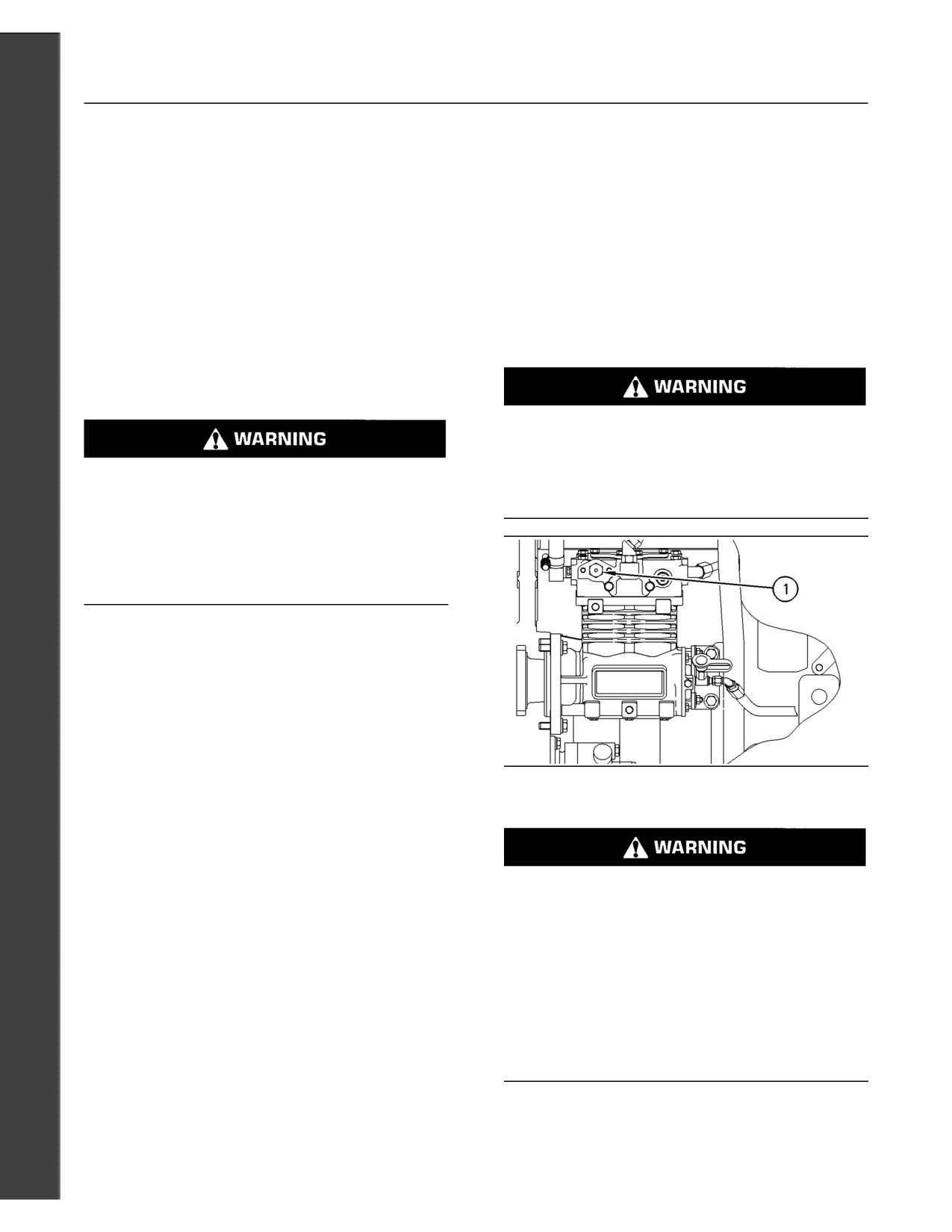
60
Maintenance Section
Aftercooler Core - Clean/Test
i01371758
Inspect these items for good condition: welds,
mounting brackets, air lines, connections, clamps,
Aftercooler Core - Clean/Test
and seals. Make repairs, if necessary.
(Air-To-Air Aftercooler)
For more detailed information on cleaning and
inspection, see Special Publication, SEBD0518,
SMCS Code: 1064-070; 1064-081
“Know Your Cooling System”.
Note: Adjust the frequency of cleaning according to
the effects of the operating environment.
i01183385
Inspect the aftercooler for these items: damaged
Air Compressor - Inspect
fins, corrosion, dirt, grease, insects, leaves, oil, and
other debris. Clean the aftercooler, if necessary.
SMCS Code: 1803-040
For air-to-air aftercoolers, use the same methods
that are used for cleaning radiators.
Do not disconnect the air line from the air com-
pressor governor without purging the air brake
and the auxiliary air systems. Failure to purge the
Personal injury can result from air pressure.
air brake and the auxiliary air systems before re-
moving the air compressor and/or the air lines
Personal injury can result without following prop-
could cause personal injury.
er procedure. When using pressure air, wear a pro-
tective face shield and protective clothing.
Maximum air pressure at the nozzle must be less
than 205 kPa (30 psi) for cleaning purposes.
Pressurized air is the preferred method for removing
loose debris. Direct the air in the opposite direction
of the fan’s air flow. Hold the nozzle approximately
6 mm (0.25 inch) away from the fins. Slowly move
the air nozzle in a direction that is parallel with the
tubes. This will remove debris that is between the
tubes.
Pressurized water may also be used for cleaning.
g00633741
Illustration 29
The maximum water pressure for cleaning purposes
must be less than 275 kPa (40 psi). Use pressurized
(1) Air compressor pressure relief valve
water in order to soften mud. Clean the core from
both sides.
Use a degreaser and steam for removal of oil and
If the air compressor pressure relief valve that is
grease. Clean both sides of the core. Wash the core
mounted in the air compressor cylinder head is
with detergent and hot water. Thoroughly rinse the
bypassing compressed air, there is a malfunction
core with clean water.
in the air system, possibly ice blockage. Under
these conditions, your engine may have insuffi-
After cleaning, start the engine and accelerate the
cient air for normal brake operation.
engine to high idle rpm. This will help in the removal
of debris and drying of the core. Stop the engine.
Do not operate the engine until the reason for the
Use a light bulb behind the core in order to inspect
air bypass is identified and corrected. Failure to
the core for cleanliness. Repeat the cleaning, if
heed this warning could lead to property damage,
necessary.
personal injury, or death to the operator or by-
standers.
Inspect the fins for damage. Bent fins may be
opened with a “comb”.
The function of the air compressor pressure relief
Note: If parts of the aftercooler system are repaired
valve is to bypass air when there is a malfunction in
or replaced, a leak test is highly recommended.
the air compressor system.
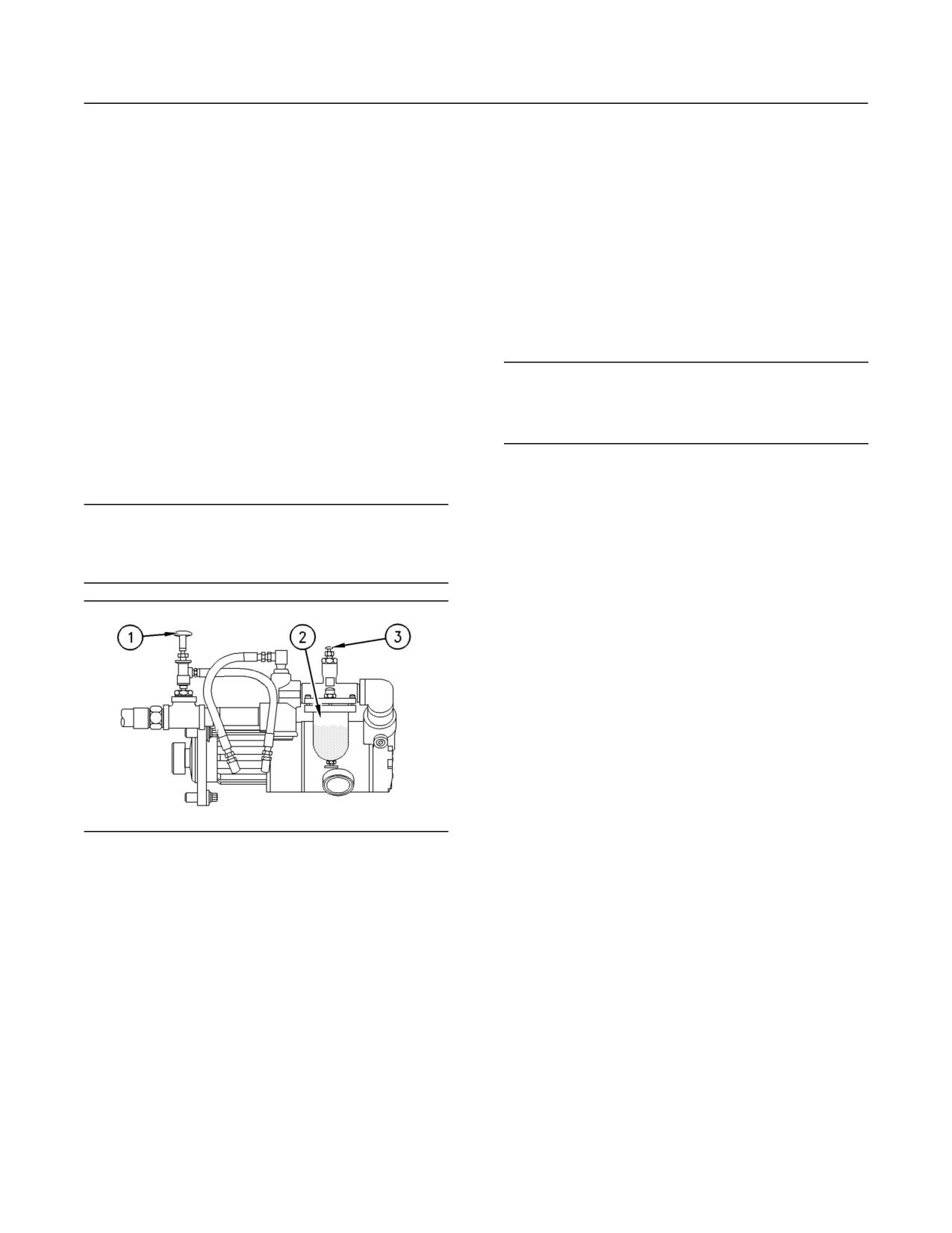
61
Maintenance Section
Air Starting Motor Lubricator Oil Level - Check
The air compressor pressure relief valve releases
Oiler Feed Adjustment
air at 1723 kPa (250 psi). It is very important that
all personnel stand clear of the air compressor
If necessary, adjust the lubricator in order to release
pressure relief valve when compressed air is
approximately two drops of fluid per 30 seconds
released. All personnel should also stay clear of the
into the starting motor air stream.
air compressor when the engine is operating and
the air compressor is exposed.
1. Ensure that the fuel supply to the engine is OFF.
Refer to the Service Manual or refer to the OEM
2. Turn adjustment knob (3) clockwise until the
specifications in order to find information concerning
adjustment knob locks.
the air compressor. Consult your Caterpillar dealer
for assistance.
3. Turn adjustment knob (3) counterclockwise for
1/4 turns.
i00805129
NOTICE
Air Starting Motor Lubricator
Do not crank the engine continuously for more than
30 seconds. Allow the starting motor to cool for two
Oil Level - Check
minutes before cranking the engine again.
(If Equipped)
4. Crank the starting motor for ten seconds and
SMCS Code: 1451-535
observe the exhaust air from the mufflers of the
starting motor. Look for oil mist. A slight oil mist
NOTICE
should be barely visible.
Never allow the lubricator bowl to become empty. The
air starting motor will be damaged by a lack of lubrica-
If no mist is observed, or if the mist is excessive,
tion. Ensure that sufficient oil is in the lubricator bowl.
rotate adjustment knob (3) in increments of 1/16 in
order to increase or decrease the oil mist. Repeat
the starting motor cranking and observe until the
mist is satisfactory.
Note: Drip rates should only be made under an
average steady flow condition. Once a steady
flow condition is established, the lubricator will
automatically adjust the drip rate in proportion to
the variations in air flow.
i00847451
Air Tank Moisture and
Sediment - Drain
g00381232
Illustration 30
(If Equipped)
(1) Air valve
(2) Lubricator bowl
SMCS Code: 1466-543-M&S
(3) Adjustment knob
Moisture and sediment in the air starting system
1. The vanes of the air starting motor are lubricated
can cause the following conditions:
with a fine mist of oil from the air starting motor
lubricator. Check the level of oil in lubricator bowl
(2). If the oil level is less than 1/2, add oil to the
• Freezing
lubricator bowl.
• Corrosion of internal parts
2. Ensure that the air supply to the lubricator is OFF.
• Malfunction of the air starting system
3. Remove the plug. Pour oil into lubricator bowl
(2). Use “10W” oil for temperatures that are
greater than 0 C (32 F). Use air tool oil for
temperatures that are below 0 C (32 F).
4. Install the plug.
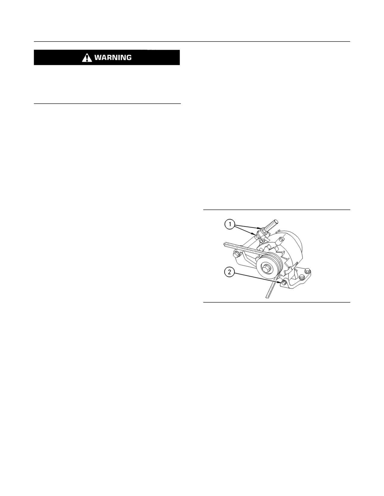
62
Maintenance Section
Alternator - Inspect
i00165437
Alternator Belt -
When opening the drain valve, wear protective
gloves, a protective face shield, protective cloth-
Inspect/Adjust/Replace
ing, and protective shoes. Pressurized air could
SMCS Code: 1357-036; 1357-510
cause debris to be blown and result in personal
injury.
Inspection
1. Open the drain valve that is on the bottom of
To maximize the engine performance, inspect the
the air tank. Allow the moisture and sediment
belt for wear and for cracking. Check the belt
to drain.
tension. Adjust the belt tension in order to minimize
belt slippage. Belt slippage will decrease the life
2. Close the drain valve.
of the belt.
3. Check the air supply pressure. The air starting
To check the belt tension, apply 110 N (25 lb)
motor requires a minimum of 620 kPa (90 psi) of
of force midway between the pulleys. A
air pressure to operate properly. The maximum
correctly adjusted belt will deflect 13 to 19 mm
air pressure must not exceed 1550 kPa (225 psi).
(0.50 to 0.75 inch).
The normal air pressure will be 758 to 965 kPa
(110 to 140 psi).
Adjustment
i00072207
Alternator - Inspect
SMCS Code: 1405-040
Caterpillar recommends a scheduled inspection
of the alternator. Inspect the alternator for loose
connections and proper battery charging. Inspect
the ammeter (if equipped) during engine operation
in order to ensure proper battery performance
and/or proper performance of the electrical system.
Make repairs, as required. Refer to the Service
Manual.
g00122875
Check the alternator and the battery charger for
Illustration 31
proper operation. If the batteries are properly
Typical Adjusting Nuts (1) and Mounting Bolt (2)
charged, the ammeter reading should be very near
zero. All batteries should be kept charged. The
1. Remove the belt guard.
batteries should be kept warm because temperature
affects the cranking power. If the battery is too cold,
2. Loosen mounting bolt (2) and adjusting nuts (1).
the battery will not crank the engine. The battery will
not crank the engine, even if the engine is warm.
3. Turn adjusting nuts (1) in order to increase or
When the engine is not run for long periods of time
decrease the belt tension.
or if the engine is run for short periods, the batteries
may not fully charge. A battery with a low charge will
4. Tighten adjusting nuts (1). Tighten mounting bolt
freeze more easily than a battery with a full charge.
(2). Refer to the Operation and Maintenance
Manual for the proper torques.
5. Reinstall the belt guard.
If new belts are installed, check the belt adjustment
again after 30 minutes of engine operation at the
rated rpm.
63
Maintenance Section
Battery - Replace
Replacement
7. Connect the cable from the starting motor to the
POSITIVE “+” battery terminal.
For applications that require multiple drive belts,
replace the belts in matched sets. Replacing only
8. Connect the cable from the ground plane to the
one belt of a matched set will cause the new belt
NEGATIVE “-” battery terminal.
to carry more load because the older belts are
stretched. The additional load on the new belt could
i01206348
cause the new belt to break.
Battery Electrolyte Level -
Refer to the Service Manual for more information on
the procedures for the following topics: belt removal
Check
and belt installation.
SMCS Code: 1401-535
i01179608
When the engine is not run for long periods of
time or when the engine is run for short periods,
Battery - Replace
the batteries may not fully recharge. Ensure a full
charge in order to help prevent the battery from
SMCS Code: 1401-510
freezing. If batteries are properly charged, ammeter
reading should be very near zero.
Batteries give off combustible gases which can
explode. A spark can cause the combustible gas-
All lead-acid batteries contain sulfuric acid which
es to ignite. This can result in severe personal in-
can burn the skin and clothing. Always wear a face
jury or death.
shield and protective clothing when working on or
near batteries.
Ensure proper ventilation for batteries that are in
an enclosure. Follow the proper procedures in or-
der to help prevent electrical arcs and/or sparks
1. Remove the filler caps. Maintain the electrolyte
near batteries. Do not smoke when batteries are
level to the “FULL” mark on the battery.
serviced.
If the addition of water is necessary, use distilled
water. If distilled water is not available use
1. Turn the key start switch to the OFF position.
clean water that is low in minerals. Do not use
Remove the key and all electrical loads.
artificially softened water.
2. Turn OFF the battery charger. Disconnect the
2. Check the condition of the electrolyte with the
charger.
1U-7298 Coolant/Battery Tester ( C) or the
1U-7297 Coolant/Battery Tester ( F).
3. The NEGATIVE “-” cable connects the NEGATIVE
“-” battery terminal to the ground plane.
3. Keep the batteries clean.
Disconnect the cable from the NEGATIVE “-”
battery terminal.
Clean the battery case with one of the following
cleaning solutions:
4. The POSITIVE “+” cable connects the POSITIVE
“+” battery terminal to the starting motor.
Disconnect the cable from the POSITIVE “+”
• A mixture of 0.1 L (0.11 qt) of baking soda and
1 L (1 qt) of clean water
battery terminal.
Note: Always recycle a battery. Never discard a
• A mixture of 0.1 L (0.11 qt) of ammonia and
1 L (1 qt) of clean water
battery. Return used batteries to an appropriate
recycling facility.
Thoroughly rinse the battery case with clean
water.
5. Remove the used battery.
6. Install the new battery.
Note: Before the cables are connected, ensure that
the key start switch is OFF.
64
Maintenance Section
Battery or Battery Cable - Disconnect
Use a fine grade of sandpaper to clean the
Charging the Battery
terminals and the cable clamps. Clean the items
until the surfaces are bright or shiny. DO NOT
remove material excessively. Excessive removal
of material can cause the clamps to not fit
Never disconnect any charging unit circuit or bat-
properly. Coat the clamps and the terminals with
tery circuit cable from the battery when the charg-
5N-5561 Silicone Lubricant, petroleum jelly or
ing unit is operated. A spark can cause an explo-
MPGM grease.
sion from the flammable vapor mixture of hydro-
gen and oxygen that is released from the elec-
i00095575
trolyte through the battery outlets. Injury to per-
sonnel can be the result.
Battery or Battery Cable -
Disconnect
Perform the following procedure to charge the
battery:
SMCS Code: 1402-029
1. Ensure that the charger is turned OFF.
1. Turn the start switch to the OFF position. Turn the
ignition switch (if equipped) to the OFF position
2. Adjust the voltage of the charger in order to
and remove the key and all electrical loads.
match the voltage of the battery.
2. Disconnect the negative battery terminal at the
3. Connect the POSITIVE “+” lead of the charger
battery that goes to the start switch. Ensure that
to the POSITIVE “+” battery terminal. Connect
the cable cannot contact the terminal. When four
the NEGATIVE “-” lead of the charger to the
12 volt batteries are involved, the negative side
NEGATIVE “-” battery terminal.
of two batteries must be disconnected.
4. Turn ON the battery charger.
3. Tape the leads in order to help prevent accidental
starting.
Overcharging of Batteries
4. Proceed with necessary system repairs. Reverse
Overcharging reduces the service life of batteries.
the steps in order to reconnect all of the cables.
Use a battery charger that will not overcharge the
battery. DO NOT charge the battery if the meter of
the battery charger is in the RED zone.
i01039758
Battery Charger - Check
Overcharging is indicated by the following
symptoms:
SMCS Code: 1401-535
• The battery is very warm to the touch.
Checking Before Start-Up
• A strong odor of acid is present.
Check the battery charger for proper operation. If
• The battery emits smoke or a dense vapor (gas).
the batteries are properly charged, the needle of
the ammeter will register near “0” (zero).
Perform one of the following procedures if the
battery shows symptoms of overcharging:
The battery charger must not produce excessive
current during start-up. Alternatively, the charger
• Reduce the rate of charging by a significant
must be automatically disconnected for start-up.
amount. Complete the charging at the reduced
If the engine has an alternator, the charger must
rate.
be automatically disconnected during start-up and
during engine operation.
• Turn OFF the charger.
Table 34 describes the effects of overcharging on
different types of batteries.
65
Maintenance Section
Cooling System Coolant (DEAC) - Change
Table 34
Note: Inspect the water pump and the water
temperature regulator after the cooling system has
Effects of Overcharging Batteries
been drained. This is a good opportunity to replace
Type of Battery
Effect
the water pump, the water temperature regulator
and the hoses, if necessary.
Caterpillar General Service
All of the battery cells have
Batteries
a low level of electrolyte.
Drain
Caterpillar Premium High
Output Batteries
Pressurized System: Hot coolant can cause seri-
ous burns. To open the cooling system filler cap,
When the plates of the
stop the engine and wait until the cooling system
battery are inspected
components are cool. Loosen the cooling system
through the filler holes, the
pressure cap slowly in order to relieve the pres-
plates may appear to be
warped. This is caused by
sure.
an excessive temperature.
The battery may not pass
1. Stop the engine and allow the engine to cool.
a load test.
Loosen the cooling system filler cap slowly
in order to relieve any pressure. Remove the
Caterpillar Maintenance
The battery may not accept
cooling system filler cap.
Free Batteries
a charging current.
The battery may not pass
2. Open the cooling system drain valve (if
a load test.
equipped). If the cooling system is not equipped
with a drain valve, remove one of the drain plugs.
Checking After Stopping
Allow the coolant to drain.
Ensure that the battery charger is connected
NOTICE
properly. Observe the meter of the charger. Record
Dispose of used engine coolant properly or recycle.
the amperage.
Various methods have been proposed to reclaim used
coolant for reuse in engine cooling systems. The full
i01206425
distillation procedure is the only method acceptable by
Caterpillar to reclaim the used coolant.
Cooling System Coolant
(DEAC) - Change
For information regarding the disposal and the
recycling of used coolant, consult your Caterpillar
SMCS Code: 1350-070; 1395-044
dealer or consult Caterpillar Service Technology
Group:
Clean the cooling system and flush the cooling
system before the recommended maintenance
Outside Illinois: 1-800-542-TOOL
interval if the following conditions exist:
Inside Illinois: 1-800-541-TOOL
Canada: 1-800-523-TOOL
• The engine overheats frequently.
Flush
• Foaming is observed.
1. Flush the cooling system with clean water in
• The oil has entered the cooling system and the
order to remove any debris.
coolant is contaminated.
2. Close the drain valve (if equipped). Clean the
• The fuel has entered the cooling system and the
drain plugs. Install the drain plugs. Refer to the
coolant is contaminated.
Operation and Maintenance Manual, “Torque
Specifications” topic (Maintenance Section) for
NOTICE
more information on the proper torques.
Use of commercially available cooling system clean-
ers may cause damage to cooling system compo-
nents. Use only cooling system cleaners that are ap-
NOTICE
proved for Caterpillar engines.
Fill the cooling system no faster than 19 L (5 US gal)
per minute to avoid air locks.
66
Maintenance Section
Cooling System Coolant (DEAC) - Change
3. Fill the cooling system with a mixture of clean
4. Start and run the engine at low idle for a
water and Caterpillar Fast Acting Cooling System
minimum of 90 minutes. The coolant temperature
Cleaner. Add 0.5 L (1 pint) of cleaner per 15 L
should be at least 82 C (180 F).
(4 US gal) of the cooling system capacity. Install
the cooling system filler cap.
NOTICE
Improper or incomplete rinsing of the cooling system
4. Start and run the engine at low idle for a
can result in damage to copper and other metal com-
minimum of 30 minutes. The coolant temperature
ponents.
should be at least 82 C (180 F).
To avoid damage to the cooling system, make sure
NOTICE
to completely flush the cooling system with clear wa-
Improper or incomplete rinsing of the cooling system
ter. Continue to flush the system until all signs of the
can result in damage to copper and other metal com-
cleaning agent are gone.
ponents.
5. Stop the engine and allow the engine to cool.
To avoid damage to the cooling system, make sure
Loosen the cooling system filler cap slowly
to completely flush the cooling system with clear wa-
in order to relieve any pressure. Remove the
ter. Continue to flush the system until all signs of the
cooling system filler cap. Open the drain valve
cleaning agent are gone.
(if equipped) or remove the cooling system
drain plugs. Allow the water to drain. Flush the
5. Stop the engine and allow the engine to cool.
cooling system with clean water. Close the drain
Loosen the cooling system filler cap slowly
valve (if equipped). Clean the drain plugs. Install
in order to relieve any pressure. Remove the
the drain plugs. Refer to the Operation and
cooling system filler cap. Open the drain valve
Maintenance Manual, “Torque Specifications”
(if equipped) or remove the cooling system
topic (Maintenance Section) for more information
drain plugs. Allow the water to drain. Flush the
on the proper torques.
cooling system with clean water. Close the drain
valve (if equipped). Clean the drain plugs. Install
Fill
the drain plugs. Refer to the Operation and
Maintenance Manual, “Torque Specifications”
NOTICE
topic (Maintenance Section) for more information
Fill the cooling system no faster than 19 L (5 US gal)
on the proper torques.
per minute to avoid air locks.
Cooling Systems with Heavy
1. Fill the cooling system with coolant/antifreeze.
Deposits or Plugging
Refer to the Operation and Maintenance
Manual, “Cooling System Specifications” topic
Note: For the following procedure to be effective,
(Maintenance Section) for more information on
there must be some active flow through the cooling
cooling system specifications. Do not install the
system components.
cooling system filler cap.
1. Flush the cooling system with clean water in
2. Start and run the engine at low idle. Increase the
order to remove any debris.
engine rpm to 1500 rpm. Run the engine at high
idle for one minute in order to purge the air from
2. Close the drain valve (if equipped). Clean the
the cavities of the engine block. Stop the engine.
drain plugs. Install the drain plugs. Refer to the
Operation and Maintenance Manual, “Torque
3. Check the coolant level. Maintain the coolant
Specifications” topic (Maintenance Section) for
level within 13 mm (0.5 inch) below the bottom
more information on the proper torques.
of the pipe for filling. Maintain the coolant level
within 13 mm (0.5 inch) to the proper level on the
NOTICE
sight glass (if equipped).
Fill the cooling system no faster than 19 L (5 US gal)
per minute to avoid air locks.
3. Fill the cooling system with a mixture of clean
water and Caterpillar Fast Acting Cooling System
Cleaner. Add 0.5 L (1 pint) of cleaner per
3.8 to 7.6 L (1 to 2 US gal) of the cooling system
capacity. Install the cooling system filler cap.
67
Maintenance Section
Cooling System Coolant (ELC) - Change
4. Clean the cooling system filler cap. Inspect the
1. Stop the engine and allow the engine to cool.
gasket that is on the cooling system filler cap. If
Loosen the cooling system filler cap slowly
the gasket that is on the cooling system filler cap
in order to relieve any pressure. Remove the
is damaged, discard the old cooling system filler
cooling system filler cap.
cap and install a new cooling system filler cap.
If the gasket that is on the cooling system filler
2. Open the cooling system drain valve (if
cap is not damaged, perform a pressure test. A
equipped). If the cooling system is not equipped
9S-8140 Pressurizing Pump is used to perform
with a drain valve, remove the cooling system
the pressure test. The correct pressure for the
drain plugs.
cooling system filler cap is stamped on the face
of the cooling system filler cap. If the cooling
Allow the coolant to drain.
system filler cap does not retain the correct
pressure, install a new cooling system filler cap.
NOTICE
Dispose of used engine coolant properly or recycle.
5. Start the engine. Inspect the cooling system for
Various methods have been proposed to reclaim used
leaks and for proper operating temperature.
coolant for reuse in engine cooling systems. The full
distillation procedure is the only method acceptable by
Caterpillar to reclaim the used coolant.
i01206445
Cooling System Coolant (ELC)
For information regarding the disposal and the
- Change
recycling of used coolant, consult your Caterpillar
dealer or consult Caterpillar Service Technology
SMCS Code: 1350-070; 1395-044
Group:
Clean the cooling system and flush the cooling
Outside Illinois: 1-800-542-TOOL
system before the recommended maintenance
Inside Illinois: 1-800-541-TOOL
interval if the following conditions exist:
Canada: 1-800-523-TOOL
• The engine overheats frequently.
Flush
• Foaming is observed.
1. Flush the cooling system with clean water in
order to remove any debris.
• The oil has entered the cooling system and the
coolant is contaminated.
2. Close the drain valve (if equipped). Clean the
drain plugs. Install the drain plugs. Refer to the
• The fuel has entered the cooling system and the
Operation and Maintenance Manual, “Torque
coolant is contaminated.
Specifications” topic (Maintenance Section) for
more information on the proper torques.
Note: When the cooling system is cleaned, only
clean water is needed when the ELC is drained
NOTICE
and replaced.
Fill the cooling system no faster than 19 L (5 US gal)
Note: Inspect the water pump and the water
per minute to avoid air locks.
temperature regulator after the cooling system has
been drained. This is a good opportunity to replace
3. Fill the cooling system with clean water. Install
the water pump, the water temperature regulator
the cooling system filler cap.
and the hoses, if necessary.
4. Start and run the engine at low idle until the
Drain
temperature reaches 49 to 66 C (120 to 150 F).
Pressurized System: Hot coolant can cause seri-
ous burns. To open the cooling system filler cap,
stop the engine and wait until the cooling system
components are cool. Loosen the cooling system
pressure cap slowly in order to relieve the pres-
sure.
68
Maintenance Section
Cooling System Coolant Extender (ELC) - Add
5. Stop the engine and allow the engine to cool.
i00259474
Loosen the cooling system filler cap slowly
Cooling System Coolant
in order to relieve any pressure. Remove the
cooling system filler cap. Open the drain valve
Extender (ELC) - Add
(if equipped) or remove the cooling system
drain plugs. Allow the water to drain. Flush the
SMCS Code: 1352-045; 1395-081
cooling system with clean water. Close the drain
valve (if equipped). Clean the drain plugs. Install
Caterpillar Extended Life Coolant (ELC) does not
the drain plugs. Refer to the Operation and
require the frequent Supplemental Coolant Additive
Maintenance Manual, “Torque Specifications”
(SCA) additions associated with the present
topic (Maintenance Section) for more information
conventional coolants. The Extender only needs to
on the proper torques.
be added once.
Fill
Check the cooling system only when the engine is
stopped and cool.
NOTICE
1. Loosen the cooling system filler cap slowly in
Fill the cooling system no faster than 19 L (5 US gal)
order to relieve pressure. Remove the cooling
per minute to avoid air locks.
system filler cap.
1. Fill the cooling system with Extended Life Coolant
2. It may be necessary to drain enough coolant
(ELC). Refer to the Operation and Maintenance
from the cooling system in order to add the
Manual, “Cooling System Specifications” topic
Extender.
(Maintenance Section) for more information on
cooling system specifications. Do not install the
3. Add Extender according to the requirements for
cooling system filler cap.
your engine’s cooling system capacity. Refer to
the Operation and Maintenance Manual, “Refill
2. Start and run the engine at low idle. Increase the
Capacities” in the Maintenance Section for the
engine rpm to high idle. Run the engine at high
capacity of the cooling system for your engine.
idle for one minute in order to purge the air from
Refer to the Operation and Maintenance Manual,
the cavities of the engine block. Stop the engine.
“Cooling System Specifications” information for
the Caterpillar ELC Extender additions.
3. Check the coolant level. Maintain the coolant
level within 13 mm (0.5 inch) below the bottom
4. Clean the cooling system filler cap. Inspect the
of the pipe for filling. Maintain the coolant level
cooling system filler cap gaskets. Replace the
within 13 mm (0.5 inch) to the proper level on the
cooling system filler cap if the cooling system
sight glass (if equipped).
filler cap gaskets are damaged. Install the
cooling system filler cap.
4. Clean the cooling system filler cap. Inspect the
gasket that is on the cooling system filler cap. If
i01197583
the gasket that is on the cooling system filler cap
is damaged, discard the old cooling system filler
Cooling System Coolant Level
cap and install a new cooling system filler cap. If
the gasket that is on the cooling system filler cap
- Check
is not damaged, use a 9S-8140 Pressurizing
Pump in order to pressure test the cooling
SMCS Code: 1395-082
system filler cap. The correct pressure for the
cooling system filler cap is stamped on the face
Check the coolant level when the engine is stopped
of the cooling system filler cap. If the cooling
and cool.
system filler cap does not retain the correct
pressure, install a new cooling system filler cap.
5. Start the engine. Inspect the cooling system for
leaks and for proper operating temperature.
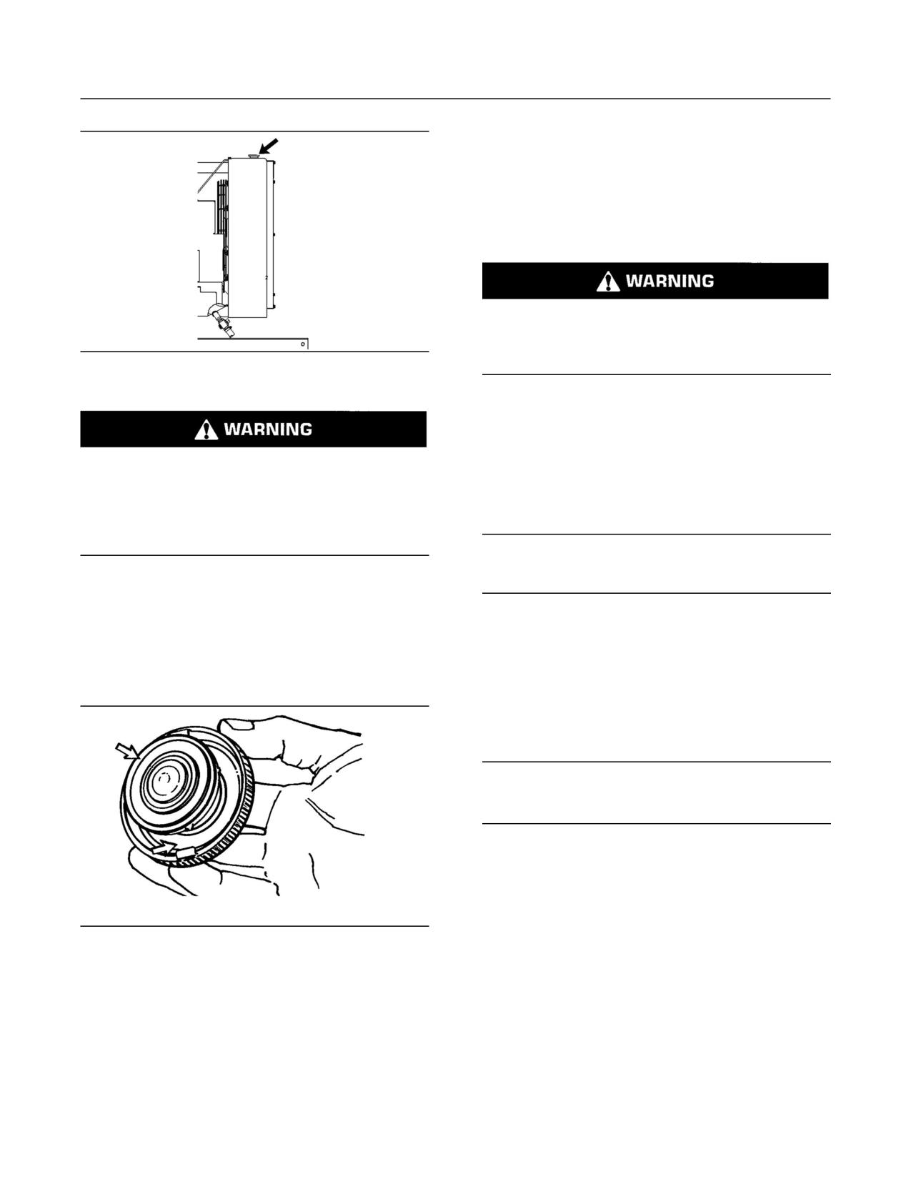
69
Maintenance Section
Cooling System Supplemental Coolant Additive (SCA) - Test/Add
i00992487
Cooling System Supplemental
Coolant Additive (SCA) -
Test/Add
SMCS Code: 1352-045; 1395-081
Cooling system coolant additive contains alkali.
To help prevent personal injury, avoid contact with
the skin and the eyes. Do not drink cooling system
g00285520
coolant additive.
Illustration 32
Cooling system filler cap
Note: Test the concentration of the Supplemental
Coolant Additive (SCA) or test the SCA concentration
as part of an S·O·S Coolant Analysis.
Pressurized System: Hot coolant can cause seri-
ous burns. To open the cooling system filler cap,
Test for SCA Concentration
stop the engine and wait until the cooling system
components are cool. Loosen the cooling system
Coolant/Antifreeze and SCA
pressure cap slowly in order to relieve the pres-
sure.
NOTICE
Do not exceed the recommended six percent supple-
1. Remove the cooling system filler cap slowly in
mental coolant additive concentration.
order to relieve pressure.
Use the 8T-5296 Coolant Conditioner Test Kit
2. Maintain the coolant level within 13 mm (0.5 inch)
or use the 4C-9301 Coolant Conditioner Test Kit
of the bottom of the filler pipe. If the engine is
in order to check the concentration of the SCA.
equipped with a sight glass, maintain the coolant
Refer to the Operation and Maintenance Manual for
level to the proper level in the sight glass.
more information on conventional coolant/antifreeze
cooling system maintenance.
Water and SCA
NOTICE
Do not exceed the recommended eight percent sup-
plemental coolant additive concentration.
Test the concentration of the SCA with the 8T-5296
Coolant Conditioner Test Kit. Refer to the Operation
and Maintenance Manual, “Water/Supplemental
Coolant Additive (SCA)” topic (Maintenance
Section). Refer to the Operation and Maintenance
g00103639
Manual, “Conventional Coolant/Antifreeze Cooling
Illustration 33
System Maintenance” topic (Maintenance Section).
Typical filler cap gaskets
3. Clean the cooling system filler cap and check the
S·O·S Coolant Analysis
condition of the filler cap gaskets. Replace the
S·O·S coolant samples can be analyzed at your
cooling system filler cap if the filler cap gaskets
are damaged. Reinstall the cooling system filler
Caterpillar dealer. S·O·S Coolant Analysis is a
cap.
program that is based on periodic samples.
4. Inspect the cooling system for leaks.
70
Maintenance Section
Cooling System Water Temperature Regulator - Replace
Level 1
3. Add the proper amount of SCA. Refer to the
Operation and Maintenance Manual for more
Level 1 is a basic analysis of the coolant. The
information on SCA requirements.
following items are tested:
4. Clean the cooling system filler cap. Inspect the
• Glycol Concentration
gaskets of the cooling system filler cap. If the
gaskets are damaged, replace the old cooling
• Concentration of SCA
system filler cap with a new cooling system filler
cap. Install the cooling system filler cap.
• pH
i00912898
• Conductivity
Cooling System Water
The results are reported, and recommendations
are made according to the results. Consult your
Temperature Regulator -
Caterpillar dealer for information on the benefits of
Replace
managing your equipment with an S·O·S Coolant
Analysis.
SMCS Code: 1355-510
Add the SCA, If Necessary
Replace the water temperature regulator before
the water temperature regulator fails. This is a
recommended preventive maintenance practice.
NOTICE
Replacing the water temperature regulator reduces
Do not exceed the recommended amount of sup-
the chances for unscheduled downtime.
plemental coolant additive concentration. Excessive
supplemental coolant additive concentration can form
A water temperature regulator that fails in a
deposits on the higher temperature surfaces of the
partially opened position can cause overheating or
cooling system, reducing the engine’s heat transfer
overcooling of the engine.
characteristics. Reduced heat transfer could cause
cracking of the cylinder head and other high temper-
A water temperature regulator that fails in the
ature components. Excessive supplemental coolant
closed position can cause excessive overheating.
additive concentration could also result in radiator
Excessive overheating could result in cracking of
tube blockage, overheating, and/or accelerated water
the cylinder head or piston seizure problems.
pump seal wear. Never use both liquid supplemental
coolant additive and the spin-on element (if equipped)
A water temperature regulator that fails in the open
at the same time. The use of those additives together
position will cause the engine operating temperature
could result in supplemental coolant additive concen-
to be too low during partial load operation. Low
tration exceeding the recommended maximum.
engine operating temperatures during partial loads
could cause an excessive carbon buildup inside
the cylinders. This excessive carbon buildup could
result in an accelerated wear of the piston rings and
wear of the cylinder liner.
Pressurized System: Hot coolant can cause seri-
ous burns. To open the cooling system filler cap,
stop the engine and wait until the cooling system
NOTICE
components are cool. Loosen the cooling system
Failure to replace your water temperature regulator
pressure cap slowly in order to relieve the pres-
on a regularly scheduled basis could cause severe
sure.
engine damage.
Caterpillar engines incorporate a shunt design cooling
1. Slowly loosen the cooling system filler cap in
system and require operating the engine with a water
order to relieve the pressure. Remove the cooling
temperature regulator installed.
system filler cap.
If the water temperature regulator is installed incor-
Note: Always discard drained fluids according to
rectly, the engine may overheat, causing cylinder head
local regulations.
damage. Ensure that the new water temperature reg-
ulator is installed in the original position. Ensure that
2. If necessary, drain some coolant from the cooling
the water temperature regulator vent hole is open.
system into a suitable container in order to allow
space for the extra SCA.
Do not use liquid gasket material on the gasket or
cylinder head surface.
71
Maintenance Section
Crankshaft Vibration Damper - Inspect
Refer to the Service Manual for the replacement
Visconic Damper
procedure of the water temperature regulator, or
consult your Caterpillar dealer.
Your engine may be equipped with a visconic
damper. The visconic damper has a weight that is
Note: If only the water temperature regulators are
located inside a fluid filled case. The weight moves
replaced, drain the coolant from the cooling system
in the case in order to limit torsional vibration.
to a level that is below the water temperature
regulator housing.
Inspect the damper for evidence of fluid leaks. If
a fluid leak is found, determine the type of fluid.
The fluid in the damper is silicone. Silicone has
i00894991
the following characteristics: transparent, viscous,
smooth, and difficult to remove from surfaces.
Crankshaft Vibration Damper
- Inspect
If the fluid leak is oil, inspect the crankshaft seals for
leaks. If a leak is observed, replace the crankshaft
SMCS Code: 1205-040
seals.
Damage to the crankshaft vibration damper or
Inspect the damper and repair or replace the
failure of the crankshaft vibration damper can
damper for any of the following reasons:
increase torsional vibrations. This can result in
damage to the crankshaft and to other engine
• The damper is dented, cracked, or leaking.
components. A deteriorating damper can cause
excessive gear train noise at variable points in the
• The paint on the damper is discolored from heat.
speed range.
The engine has had a failure because of a broken
•
The damper is mounted to the crankshaft which is
crankshaft.
located behind the belt guard on the front of the
engine.
• Analysis of the oil has revealed that the front main
bearing is badly worn.
Rubber Damper
There is a large amount of gear train wear that is
•
not caused by a lack of oil.
Your engine may be equipped with a rubber
damper. The rubber damper uses a ring which is
Refer to the Service Manual or consult your
mounted in rubber in order to reduce vibrations in
Caterpillar dealer for information about damper
the crankshaft.
replacement.
Inspect the damper and repair or replace the
damper for any of the following reasons:
i00174798
• There is deterioration and cracking of the rubber.
Driven Equipment - Check
• There is slippage of the outer ring from the
SMCS Code: 3279-535
original position.
Refer to the OEM specifications for more information
• The engine has had a failure because of a broken
on the following maintenance recommendations for
crankshaft.
the driven equipment:
• Analysis of the oil has revealed that the front main
• Inspection
bearing is badly worn.
• Adjustment
• There is a large amount of gear train wear that is
not caused by lack of oil.
• Lubrication
Refer to the Service Manual or consult your
• Other maintenance recommendations
Caterpillar dealer for information about damper
replacement.
Perform any maintenance for the driven equipment
which is recommended by the OEM.
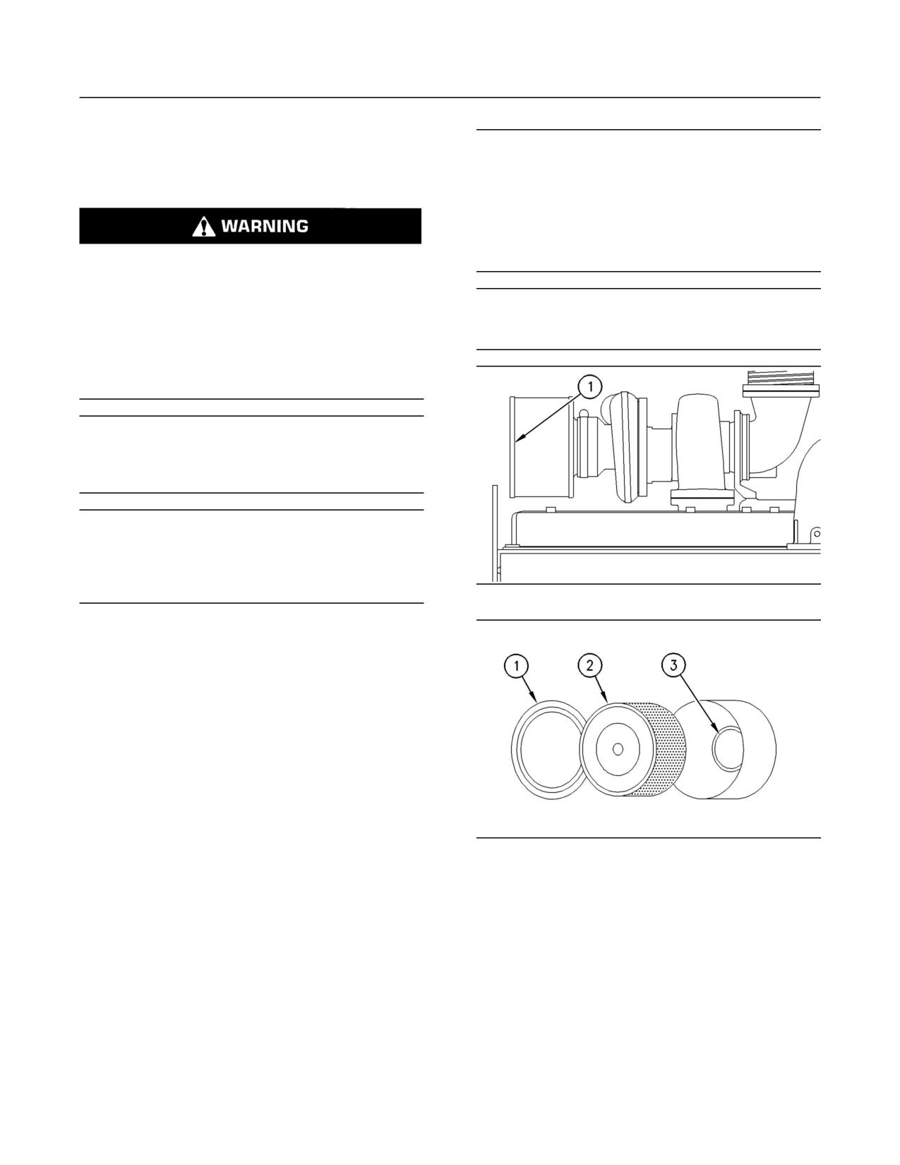
72
Maintenance Section
Engine - Clean
i01239442
NOTICE
Engine - Clean
Never run the engine without an air cleaner element
installed. Never run the engine with a damaged air
SMCS Code: 1000-070
cleaner element. Do not use air cleaner elements with
damaged pleats, gaskets or seals. Dirt entering the
engine causes premature wear and damage to engine
components. Air cleaner elements help to prevent air-
Personal injury or death can result from high volt-
borne debris from entering the air inlet.
age.
Moisture can create paths of electrical conductiv-
NOTICE
ity.
Never service the air cleaner element with the engine
running since this will allow dirt to enter the engine.
Make sure that the electrical system is OFF. Lock
out the starting controls and tag the controls “DO
NOT OPERATE”.
NOTICE
Water and/or condensation can cause damage to
electrical components. Protect all electrical compo-
nents from exposure to water.
NOTICE
Accumulated grease and oil on an engine is a fire haz-
ard. Keep the engine clean. Remove debris and fluid
spills whenever a significant quantity accumulates on
the engine.
g00310663
Illustration 34
Periodic cleaning of the engine is recommended.
Steam cleaning the engine will remove accumulated
oil and grease. A clean engine provides the
following benefits:
• Easy detection of fluid leaks
• Maximum heat transfer characteristics
• Ease of maintenance
i01173387
Engine Air Cleaner
g00310664
Illustration 35
Element (Single Element) -
1. Remove the air cleaner cover (1) and remove
Inspect/Replace
the element (2).
SMCS Code: 1054-040; 1054-510
2. Seal the air inlet (3) so that debris cannot enter
the air inlet. Tape or a clean cloth can be used
Perform the Operation and Maintenance Manual,
to cover the opening.
“Engine Air Cleaner Service Indicator-Inspect”
procedure and perform the Operation and
3. Clean the inside of the air cleaner cover. Clean
Maintenance Manual, “Engine Air Precleaner
the body that holds the air cleaner element.
Check/Clean” procedure (if equipped) before
performing the following procedure.
4. Inspect the replacement element for the following
items:damage, dirt, and debris.
5. Remove the seal from the opening of the air inlet.
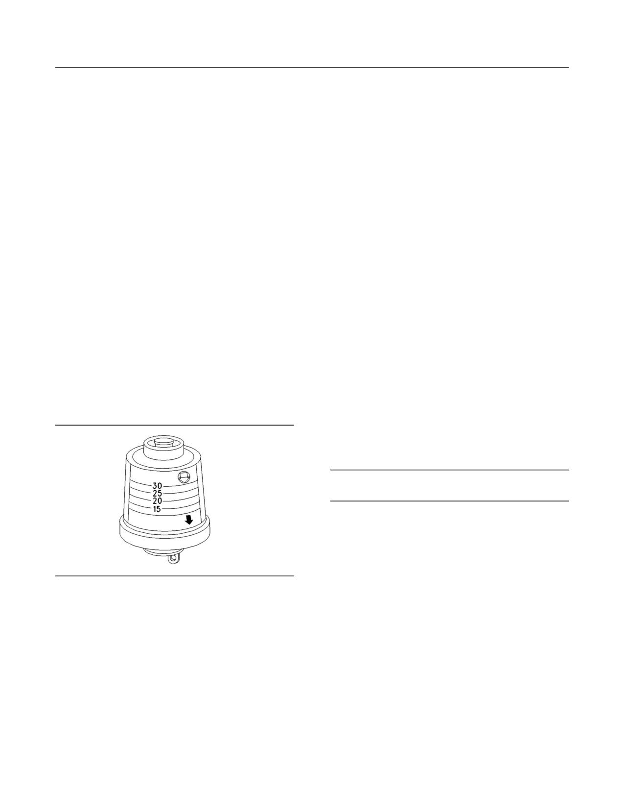
73
Maintenance Section
Engine Air Cleaner Service Indicator - Inspect
6. Install a clean, undamaged element.
• Check for ease of resetting. The service indicator
should reset in less than three pushes.
7. Install the air cleaner cover (1).
Check the movement of the yellow core when the
•
8. Reset the service indicator.
engine is accelerated to the engine rated speed.
The yellow core should latch approximately at the
greatest vacuum that is attained.
i01175055
If the service indicator does not reset easily, or if the
Engine Air Cleaner Service
yellow core does not latch at the greatest vacuum,
Indicator - Inspect
the service indicator should be replaced. If the
new service indicator will not reset, the hole for the
SMCS Code: 7452-040
service indicator may be plugged.
Some engines may be equipped with a different
The service indicator may need to be replaced
service indicator.
frequently in environments that are severely dusty, if
necessary. Replace the service indicator annually
Some engines are equipped with a differential
regardless of the operating conditions. Replace the
gauge for inlet air pressure. The differential gauge
service indicator when the engine is overhauled,
for inlet air pressure displays the difference in the
and whenever major engine components are
pressure that is measured before the air cleaner
replaced.
element and the pressure that is measured after
the air cleaner element. As the air cleaner element
Note: When a new service indicator is installed,
becomes dirty, the pressure differential rises. If your
excessive force may crack the top of the service
engine is equipped with a different type of service
indicator. Tighten the service indicator to a torque
indicator, follow the OEM recommendations in order
of 2 N·m (18 lb in).
to service the air cleaner service indicator.
i00906289
The service indicator may be mounted on the air
cleaner element or in a remote location.
Engine Crankcase Breather -
Clean
SMCS Code: 1317-070
NOTICE
Perform this maintenance with the engine stopped.
If the crankcase breather is not maintained on a
regular basis, the crankcase breather will become
plugged. A plugged crankcase breather will cause
excessive crankcase pressure that may cause
crankshaft seal leakage.
g00103777
Illustration 36
Typical service indicator
Observe the service indicator. The air cleaner
element should be cleaned or the air cleaner
element should be replaced when one of the
following conditions occur:
• The yellow diaphragm enters the red zone.
• The red piston locks in the visible position.
Test the Service Indicator
Service indicators are important instruments.
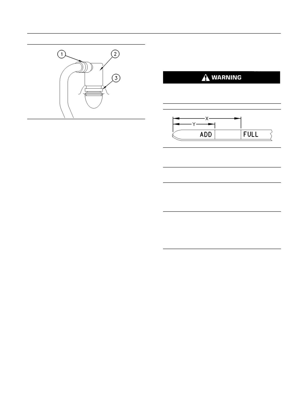
74
Maintenance Section
Engine Mounts - Inspect
i00623423
Engine Oil Level - Check
SMCS Code: 1348-535-FLV
Hot oil and hot components can cause personal
injury. Do not allow hot oil or hot components to
contact the skin.
g00463048
Illustration 37
Typical example
(1) Hose clamp
(2) Breather assembly
(3) Retaining clamp
g00110310
Illustration 38
1. Loosen hose clamp (1) and remove the hose
(Y) “ADD” mark. (X) “FULL” mark.
from breather assembly (2).
NOTICE
2. Loosen the retaining clamp (3). Remove breather
Perform this maintenance with the engine stopped.
assembly (2) and the seal.
3. Wash the breather element in solvent that is
1. Maintain the oil level between “ADD” mark (Y)
clean and nonflammable. Allow the breather
and “FULL” mark (X) on oil level gauge (1). Do
element to dry before installation.
not fill the crankcase above “FULL” mark (X).
4. Install a breather element that is clean and
dry. Install breather assembly and seal (2) and
NOTICE
Operating your engine when the oil level is above the
install clamp (3). Refer to the Operation and
Maintenance Manual, “Torque Specifications”
“FULL” mark could cause your crankshaft to dip into
topic (Maintenance Section) for the proper
the oil. The air bubbles created from the crankshaft
dipping into the oil reduces the oil’s lubricating char-
torques.
acteristics and could result in the loss of power.
5. Install the hose. Install hose clamp (1). Refer to
the Operation and Maintenance Manual, “Torque
2. Remove the oil filler cap and add oil, if necessary.
Specifications” topic (Maintenance Section) for
Clean the oil filler cap. Install the oil filler cap.
the proper torques.
i01070756
i00687861
Engine Oil Sample - Obtain
Engine Mounts - Inspect
SMCS Code: 1000-008; 1348-554-SM;
SMCS Code: 1152-040
7542-554-OC, SM
Inspect the engine mounts for deterioration and for
In addition to a good preventive maintenance
proper bolt torque. Engine vibration can be caused
program, Caterpillar recommends using S·O·S oil
by the following conditions:
analysis at regularly scheduled intervals in order
to monitor the condition of the engine and the
• Improper mounting of the engine
maintenance requirements of the engine.
• Deterioration of the engine mounts
Any engine mount that shows deterioration should
be replaced. Refer to the Service Manual for the
recommended torques. Refer to your Caterpillar
dealer for more information.
75
Maintenance Section
Engine Oil and Filter - Change
Obtain the Sample and the Analysis
If the engine is not equipped with a sampling valve,
use the 1U-5718 Vacuum Pump. The pump is
designed to accept sampling bottles. Disposable
tubing must be attached to the pump for insertion
into the sump.
Hot oil and hot components can cause personal
injury. Do not allow hot oil or hot components to
For instructions, see Special Publication, PEHP6001,
contact the skin.
“How To Take A Good Oil Sample”. Consult your
Caterpillar dealer for complete information and
assistance in establishing an S·O·S program for
Before you take the oil sample, complete the Label,
your engine.
PEEP5031 for identification of the sample. In order
to help obtain the most accurate analysis, provide
the following information:
i00652130
• Engine model
Engine Oil and Filter - Change
• Service hours on the engine
SMCS Code: 1318-510; 1348-044
• The number of hours that have accumulated
since the last oil change
Hot oil and hot components can cause personal
• The amount of oil that has been added since the
injury. Do not allow hot oil or hot components to
last oil change
contact the skin.
To ensure that the sample is representative of the
oil in the crankcase, obtain a warm, well mixed oil
Do not drain the oil when the engine is cold. As
sample.
the oil cools, suspended waste particles settle
on the bottom of the oil pan. The waste particles
To avoid contamination of the oil samples, the tools
are not removed with the draining cold oil. Drain
and the supplies that are used for obtaining oil
the crankcase with the engine stopped. Drain the
samples must be clean.
crankcase with the oil warm. This draining method
allows the waste particles that are suspended in the
Caterpillar recommends using the sampling valve
oil to be drained properly.
in order to obtain oil samples. The quality and the
consistency of the samples are better when the
Failure to follow this recommended procedure will
sampling valve is used. The location of the sampling
cause the waste particles to be recirculated through
valve allows oil that is flowing under pressure to be
the engine lubrication system with the new oil.
obtained during normal engine operation.
Drain the Engine Oil
The 8T-9190 Fluid Sampling Bottle Group is
recommended for use with the sampling valve. The
After the engine has been run at the normal
bottle group includes the parts that are needed
operating temperature, stop the engine. Use one of
for obtaining oil samples. Instructions are also
the following methods to drain the engine crankcase
provided.
oil:
NOTICE
• If the engine is equipped with a drain valve, turn
Do not use the same vacuum sampling pump for ex-
the drain valve knob counterclockwise in order to
tracting oil samples that is used for extracting coolant
drain the oil. After the oil has drained, turn the
samples.
drain valve knob clockwise in order to close the
drain valve.
A small residue of either type sample may remain in
the pump and may cause a false positive analysis for
• If the engine is not equipped with a drain valve,
the sample being taken.
remove the oil drain plug in order to allow the oil
to drain. If the engine is equipped with a shallow
Always use a designated pump for oil sampling and a
sump, remove the bottom oil drain plugs from
designated pump for coolant sampling.
both ends of the oil pan.
Failure to do so may cause a false analysis which
After the oil has drained, the oil drain plugs should
could lead to customer and dealer concerns.
be cleaned and installed.
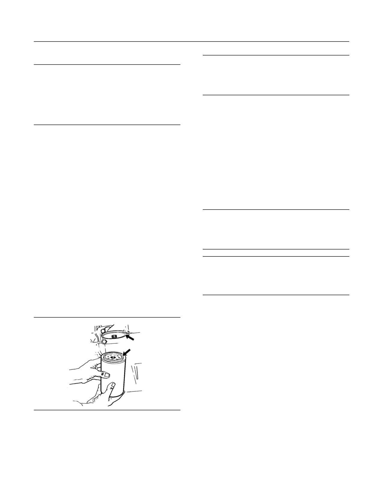
76
Maintenance Section
Engine Oil and Filter - Change
Replace the Oil Filter
NOTICE
Do not fill the oil filters with oil before installing them.
NOTICE
This oil would not be filtered and could be contaminat-
Caterpillar oil filters are built to Caterpillar speci-
ed. Contaminated oil can cause accelerated wear to
fications. Use of an oil filter not recommended by
engine components.
Caterpillar could result in severe engine damage to
the engine bearings, crankshaft, etc., as a result of
the larger waste particles from unfiltered oil entering
5. Install the oil filter. Tighten the oil filter until the
the engine lubricating system. Only use oil filters
oil filter gasket contacts the base. Tighten the oil
recommended by Caterpillar.
filter by hand according to the instructions that
are shown on the oil filter. Do not overtighten the
oil filter.
1.
Remove the oil filter with a 1U-8760 Chain
Wrench.
Fill the Engine Crankcase
2.
Cut the oil filter open with a 4C-5084 Oil Filter
Cutter. Break apart the pleats and inspect the oil
1. Remove the oil filler cap. Refer to the Operation
filter for metal debris. An excessive amount of
and Maintenance Manual for more information on
metal debris in the oil filter may indicate early
lubricant specifications. Fill the crankcase with
wear or a pending failure.
the proper amount of oil. Refer to the Operation
and Maintenance Manual for more information
Use a magnet to differentiate between the
on refill capacities.
ferrous metals and the nonferrous metals that
are found in the oil filter element. Ferrous metals
NOTICE
may indicate wear on the steel and cast iron
If equipped with an auxiliary oil filter system or a re-
parts of the engine.
mote oil filter system, follow the OEM or filter manu-
facturer’s recommendations. Under filling or overfilling
Nonferrous metals may indicate wear on the
the crankcase with oil can cause engine damage.
aluminum parts, brass parts or bronze parts of
the engine. Parts that may be affected include
the following items: main bearings, rod bearings,
NOTICE
turbocharger bearings, and cylinder heads.
To prevent crankshaft bearing damage, crank the en-
gine with the fuel OFF. This will fill the oil filters before
Due to normal wear and friction, it is not
starting the engine. Do not crank the engine for more
uncommon to find small amounts of debris in the
than 30 seconds.
oil filter. Consult your Caterpillar dealer in order
to arrange for a further analysis if an excessive
amount of debris is found in the oil filter.
2. Start the engine and run the engine at “LOW
IDLE” for two minutes. Perform this procedure in
order to ensure that the lubrication system has
oil and that the oil filters are filled. Inspect the oil
filter for oil leaks.
3. Stop the engine and allow the oil to drain back
to the sump for a minimum of ten minutes.
4. Remove the oil level gauge in order to check the
oil level. Maintain the oil level between the “ADD”
and “FULL” marks on the oil level gauge.
g00103713
Illustration 39
Typical filter mounting base and filter gasket
3. Clean the sealing surface of the filter mounting
base. Ensure that all of the old oil filter gasket
is removed.
4. Apply clean engine oil to the new oil filter gasket.
77
Maintenance Section
Engine Protective Devices - Check
i00626013
NOTICE
Engine Protective Devices -
Only qualified service personnel should perform this
Check
maintenance. Refer to the Service Manual or your
Caterpillar dealer for the complete valve lash adjust-
SMCS Code: 7400-535
ment procedure.
Alarms and shutoffs must function properly. Alarms
Operation of Caterpillar engines with improper valve
provide timely warning to the operator. Shutoffs help
adjustments can reduce engine efficiency. This re-
to prevent damage to the engine. It is impossible
duced efficiency could result in excessive fuel usage
to determine if the engine protective devices are
and/or shortened engine component life.
in good working order during normal operation.
Malfunctions must be simulated in order to test the
engine protective devices.
A calibration check of the engine protective devices
Ensure that the engine can not be started while
will ensure that the alarms and shutoffs activate
this maintenance is being performed. To help pre-
at the setpoints. Ensure that the engine protective
vent possible injury, do not use the starting motor
devices are functioning properly.
to turn the flywheel.
Hot engine components can cause burns. Allow
NOTICE
additional time for the engine to cool before mea-
During testing, abnormal operating conditions must be
suring/adjusting valve lash clearance.
simulated.
The tests must be performed correctly in order to pre-
Ensure that the engine is stopped before measuring
vent possible damage to the engine.
the valve lash. To obtain an accurate measurement,
allow the valves to cool before this maintenance
is performed.
To prevent damage to the engine, only authorized
service personnel or your Caterpillar dealer should
Refer to the Service Manual for more information.
perform the tests.
i00937014
Visual Inspection
Engine Valve Rotators - Inspect
Visually check the condition of all gauges, sensors
and wiring. Look for wiring and components that
SMCS Code: 1109-040
are loose, broken, or damaged. Damaged wiring
or components should be repaired or replaced
immediately.
When inspecting the valve rotators, protective
i00869628
glasses or face shield and protective clothing
must be worn, to help prevent being burned by
Engine Valve Lash -
hot oil or spray.
Inspect/Adjust
NOTICE
SMCS Code: 1102-025
A valve rotator which does not operate properly will
accelerate valve face wear and valve seat wear and
The initial valve lash adjustment on new engines,
shorten valve life. If a damaged rotator is not replaced,
rebuilt engines, or remanufactured engines is
valve face guttering could result and cause pieces of
recommended at the first scheduled oil change.
the valve to fall into the cylinder. This can cause piston
The adjustment is necessary due to the initial wear
and cylinder head damage.
of the valve train components and to the seating of
the valve train components.
Valve rotators cause the valves to rotate when the
This maintenance is recommended by Caterpillar
engine runs. This helps to prevent deposits from
as part of a lubrication and preventive maintenance
building up on the valves and the valve seats.
schedule in order to help provide maximum engine
life.
Perform the following steps after the valve lash is
set, but before the valve covers are installed:
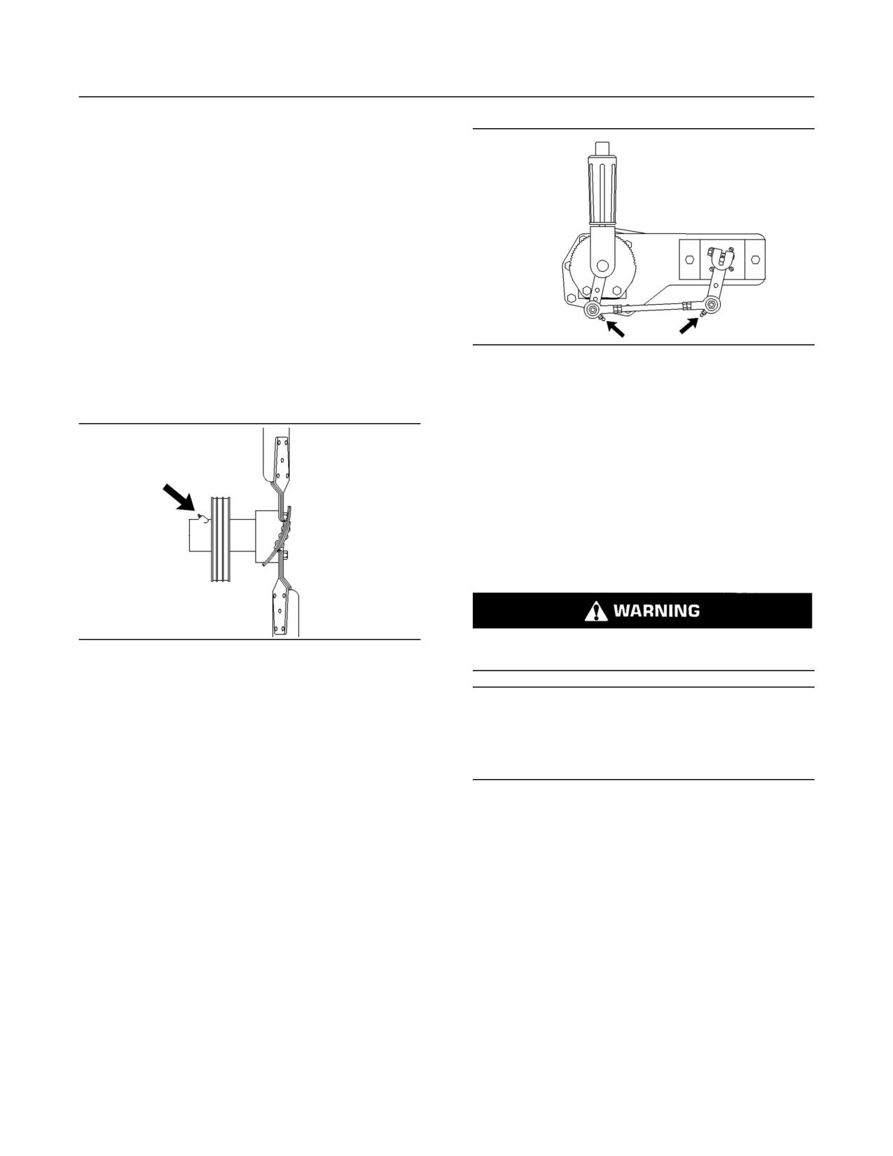
78
Maintenance Section
Fan Drive Bearing - Lubricate
1. Start the engine according to this Operation
and Maintenance Manual, “Engine Starting”
procedure (Operation Section).
Operate the engine at low idle.
2. Observe the top surface of each valve rotator.
The valve rotators should turn slightly when the
valves close.
If a valve fails to rotate, consult your Caterpillar
dealer.
i00175571
g00723120
Illustration 41
Fan Drive Bearing - Lubricate
Typical grease fittings on the fuel control linkage
SMCS Code: 1359-086-BD
Some fuel control linkages require lubrication.
Lubricate the grease fittings with 1P-0808
Multipurpose Grease or the equivalent.
i00626014
Fuel Injection Nozzles -
Test/Exchange
SMCS Code: 1254-013; 1254-081
Fuel leaked or spilled onto hot surfaces or electri-
g00123252
Illustration 40
cal components can cause a fire.
Typical Fan Drive Bearing Grease Fitting
Lubricate the fan drive bearing grease fitting with
NOTICE
Bearing Lubricant Special Purpose Grease or the
Do not allow dirt to enter the fuel system. Thoroughly
equivalent.
clean the area around a fuel system component that
will be disconnected. Fit a suitable cover over discon-
nected fuel system component.
Inspect the fan drive pulley assembly. If the shaft
is loose, an inspection of the internal components
should be performed. Refer to the Service Manual.
Fuel injection nozzles are subject to tip wear. Tip
wear is a result of fuel contamination. Tip wear can
cause the following problems:
i01370585
Fuel Control Linkage -
• Increased fuel consumption
Check/Lubricate
• Black smoke
SMCS Code: 1257-086; 1257-535
• Misfire
Check the fuel control linkage for proper operation.
• Rough running
If necessary, adjust the fuel control linkage . Refer to
the Service Manual for the adjustment procedures.
Fuel Injection nozzles should be cleaned, inspected,
tested, and replaced, if necessary. Refer to Special
Instruction, SEHS7292 for using the 8S-2245
Injection Cleaning Tool Group. Consult your
Caterpillar dealer about cleaning the fuel injection
nozzle and testing the fuel injection nozzle.
79
Maintenance Section
Fuel Ratio Control - Inspect/Adjust
i00908934
NOTICE
Fuel Ratio Control -
Never wire brush or scrape a fuel injection nozzle.
Wire brushing or scraping a fuel injection nozzle will
Inspect/Adjust
damage the finely machine orifice. Proper tools for
cleaning and testing the fuel injection nozzles can be
SMCS Code: 1278-025; 1278-040
obtained from Caterpillar dealers.
Slow engine response and low power may indicate
a need for adjustment or repair of the fuel ratio
The following items are symptoms of a malfunction
control. Refer to the Service Manual or your
of the fuel injection nozzle:
Caterpillar dealer for the complete adjustment
procedure on the fuel ratio control.
• Abnormal engine operation
• Smoke emission
i00891826
• Engine knock
Fuel System - Prime
Each fuel injection nozzle must be isolated one at a
SMCS Code: 1258-548
time in order to determine the malfunctioning fuel
injection nozzle.
1. Start the engine.
Personal injury or death can result from a fire.
2. Loosen each fuel line nut one at a time at the fuel
Fuel leaked or spilled onto hot surfaces or electri-
injection pump. A cloth or similar material must
cal components can cause a fire.
be used in order to prevent fuel from spraying on
the hot exhaust components. Tighten each nut
Clean up all leaked or spilled fuel. Do not smoke
before loosening the next nut.
while working on the fuel system.
3. A defective fuel injection nozzle may be identified
Turn the disconnect switch OFF or disconnect the
when a fuel line nut is loosened and the following
battery when changing fuel filters.
conditions are present:
Prime the fuel system in order to fill dry fuel filters.
• The exhaust smoke is partially eliminated or
the exhaust smoke is completely eliminated.
You must also prime the fuel system after any one
of the following conditions exist:
• Engine performance is not affected.
• The fuel system has run dry.
A fuel injection nozzle that is suspected of
being defective should be removed. A new
• The engine has been in prolonged storage.
fuel injection nozzle should be installed in the
cylinder in order to determine if the removed fuel
• The fuel filter has been cleaned.
injection nozzle is defective.
• The fuel filter has been replaced.
Removal and Installation of the
Note: If the engine does not have a fuel priming
Fuel Injection Nozzles
pump, refer to Step 4.
For the removal and the installation of fuel injection
1. Unlock the priming pump, and operate the
nozzles, special tooling is required. Refer to the
priming pump until a resistance is felt. This
Service Manual for more information. Consult your
procedure will probably require a considerable
Caterpillar dealer for assistance.
amount of priming.
2. Push in the plunger, and hand tighten the
plunger.
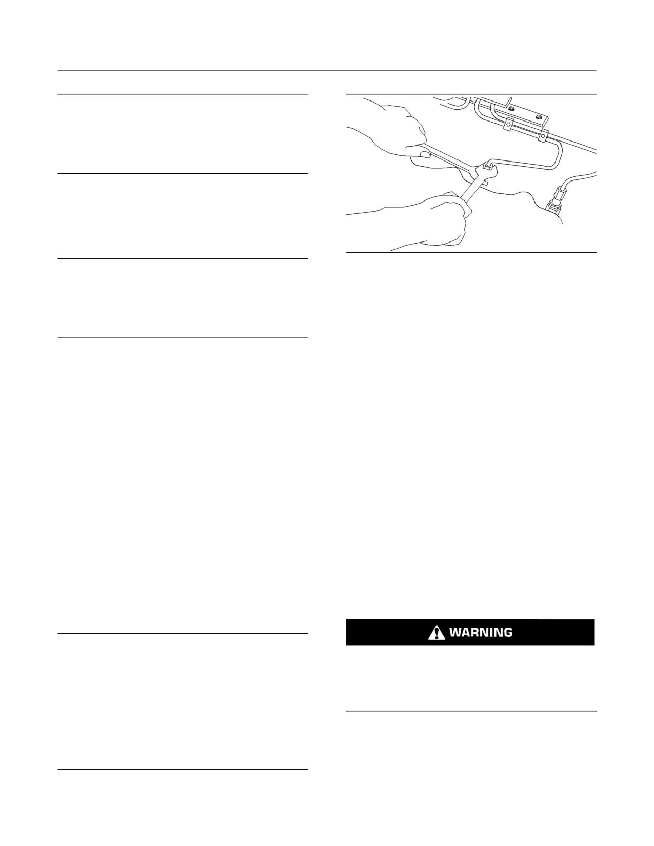
80
Maintenance Section
Fuel System Primary Filter - Clean/Replace
NOTICE
Do not crank the engine for more than 30 seconds. Al-
low the starter to cool for two minutes before cranking
again. Turbocharger damage can result if the engine
rpm is not kept low until the oil gauge display verifies
that the oil pressure is sufficient.
3. Crank the engine.
If the engine starts and the engine runs rough,
run the engine at low idle. Continue running the
engine until the engine runs smoothly.
g00290109
Illustration 42
NOTICE
During periodic service, DO NOT remove the fuel filter
8. Loosen the fuel line nuts at the valve cover base.
plug that is in the fuel filter base in order to purge air
Loosen these line nuts one at a time.
from the fuel system. The periodic removal of the fuel
filter plug will result in increased wear on the threads
9. Operate the priming pump until the flow of fuel
in the fuel filter base. This wear leads to fuel leakage.
from the fuel line is continuous and the flow of
fuel is free of air bubbles.
4. Open the vent valve (if equipped) on the fuel
injection pump’s housing.
10. Push in the plunger, and hand tighten the
plunger. If the engine does not have a fuel
5. Operate the priming pump until the flow of fuel
priming pump, crank the engine.
from the vent valve is continuous and the flow of
fuel is free of air bubbles.
11. Tighten each fuel line nut before you loosen the
next fuel line nut. Tighten the fuel line nuts to a
If the engine does not have a fuel priming pump,
torque of 40 ± 7 N·m (30 ± 5 lb ft).
crank the engine. Crank the engine until the
fuel flows freely and until the fuel is free of air
Continue this procedure until all of the fuel lines
bubbles.
have been cleared of any air. Before you start
the engine, make sure that the fuel line nuts
6. Close the vent valve. Then, push in the plunger.
are properly tightened. Also make sure that the
Hand tighten the plunger.
priming is locked.
7. Crank the engine. If the engine starts and if the
i00951418
engine runs rough, run the engine at low idle.
Continue running the engine until the engine
Fuel System Primary Filter -
runs smoothly.
Clean/Replace
Note: If the engine will not start, more priming is
necessary. If the engine continues to run rough,
SMCS Code: 1260-070; 1260-510
more priming is necessary as well.
NOTICE
Do not let the tops of fuel nozzles turn when the fuel
Fuel leaked or spilled onto hot surfaces or elec-
line nuts are loosened or tightened.
trical components can cause a fire. To help pre-
vent possible injury, turn the start switch off when
The nozzles will be damaged if the top of the nozzle
changing fuel filters or water separator elements.
turns in the body.
Clean up fuel spills immediately.
The engine will be damaged if a defective fuel injec-
1. Stop the engine.
tion nozzle is used because the shape of fuel (spray
pattern) that comes out of the nozzles will not be cor-
2. Turn the start switch to the “OFF” position.
rect.
Disconnect the battery.
3. Shut off the fuel tank supply valve to the engine.
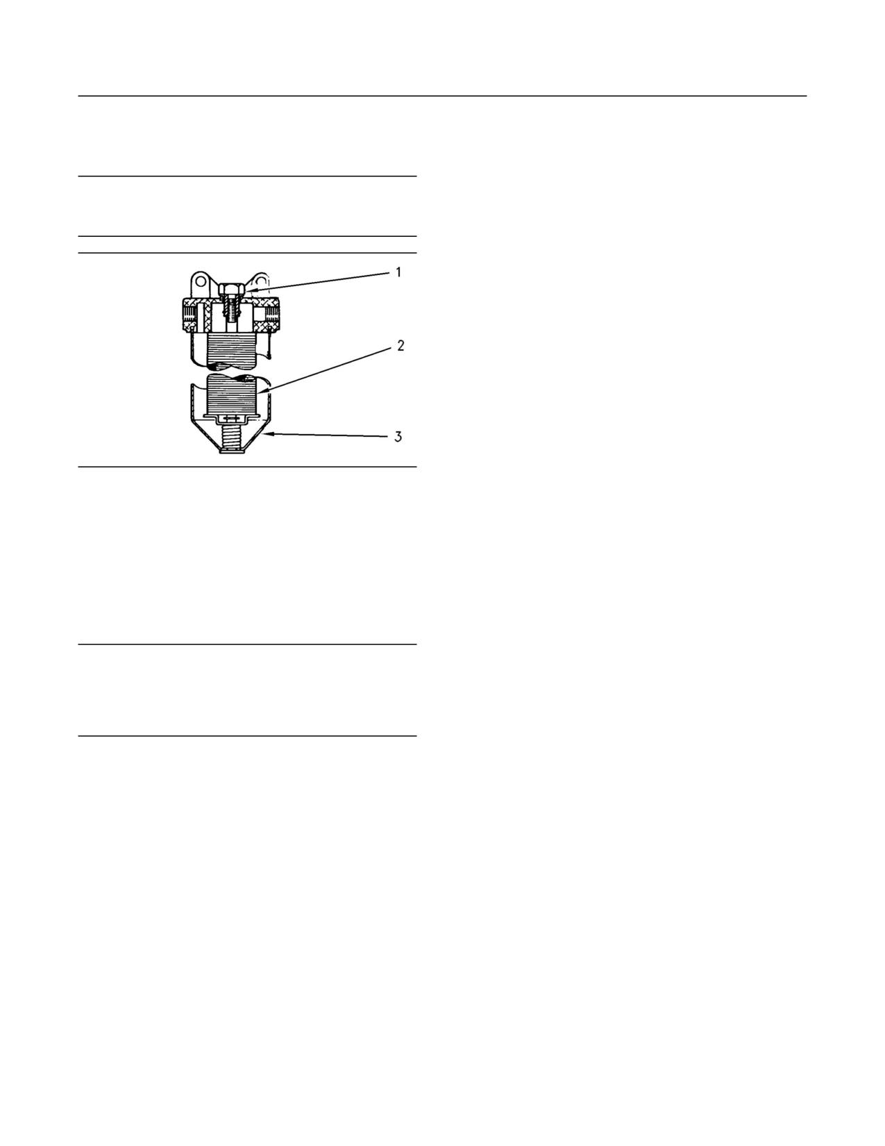
81
Maintenance Section
Fuel Tank Water and Sediment - Drain
4. If the primary fuel filter is equipped with a drain
i00073301
valve, open the drain valve in order to drain any
Fuel Tank Water and Sediment
fuel from the filter case. Close the drain valve.
- Drain
NOTICE
Use a suitable container to catch any fuel that might
SMCS Code: 1273-543-M&S
spill. Clean up any spilled fuel immediately.
Fuel Tank
Fuel quality is critical to the performance and to
the service life of the engine. Water in the fuel can
cause excessive fuel system wear. Condensation
occurs during the heating and cooling of fuel. The
condensation occurs as the fuel passes through
the fuel system and the fuel returns to the fuel tank.
This causes water to accumulate in fuel tanks.
Draining the fuel tank regularly and obtaining fuel
from reliable sources can help to eliminate water
in the fuel.
Drain the Water and the Sediment
g00485293
Illustration 43
Fuel tanks should contain some provision for
(1) Bolt
draining water and draining sediment from the
(2) Element
(3) Case
bottom of the fuel tanks.
5. Loosen the bolt (1) that is on the filter housing.
Open the drain valve on the bottom of the fuel tank
Remove the filter case (3).
in order to drain the water and the sediment. Close
the drain valve.
6. Remove the element (2) and wash the element
in clean, nonflammable solvent.
Check the fuel daily. Drain the water and sediment
from the fuel tank after operating the engine or drain
the water and sediment from the fuel tank after the
NOTICE
fuel tank has been filled. Allow five to ten minutes
Do not fill the fuel filters with fuel before installing them.
before performing this procedure.
The fuel would not be filtered and could be contami-
nated. Contaminated fuel will cause accelerated wear
Fill the fuel tank after operating the engine in
to fuel system parts.
order to drive out moist air. This will help prevent
condensation. Do not fill the tank to the top. The
7. Install the element (2) and the filter case (3).
fuel expands as the fuel gets warm. The tank may
Tighten the bolt (1) to a torque of 24 ± 4 N·m
overflow.
(18 ± 3 lb ft).
Some fuel tanks use supply pipes that allow water
and sediment to settle below the end of the fuel
supply pipe. Some fuel tanks use supply lines that
take fuel directly from the bottom of the tank. If
the engine is equipped with this system, regular
maintenance of the fuel system filter is important.
Fuel Storage Tanks
Drain the water and the sediment from the fuel
storage tank during the following conditions:
• Weekly
• Oil change
• Refill of the tank
82
Maintenance Section
Hoses and Clamps - Inspect/Replace
This will help prevent water or sediment from being
Due to extreme temperature changes, the hose
pumped from the storage tank into the engine fuel
will heat set. Heat setting causes hose clamps to
tank.
loosen. This can result in leaks. A constant torque
hose clamp will help to prevent loose hose clamps.
If a bulk storage tank has been refilled or moved
recently, allow adequate time for the sediment to
Each installation application can be different. The
settle before filling the engine fuel tank. Internal
differences depend on the following factors:
baffles in the bulk storage tank will also help trap
sediment. Filtering fuel that is pumped from the
• Type of hose
storage tank helps to ensure the quality of the fuel.
When possible, water separators should be used.
• Type of fitting material
Anticipated expansion and contraction of the
•
i00907072
hose
Hoses and Clamps -
• Anticipated expansion and contraction of the
Inspect/Replace
fittings
SMCS Code: 7554-040; 7554-510
Replace the Hoses and the Clamps
Inspect all hoses for leaks that are caused by the
following conditions:
• Cracking
Pressurized System: Hot coolant can cause seri-
ous burns. To open the cooling system filler cap,
• Softness
stop the engine and wait until the cooling system
components are cool. Loosen the cooling system
• Loose clamps
pressure cap slowly in order to relieve the pres-
sure.
Replace hoses that are cracked or soft. Tighten any
loose clamps.
1. Stop the engine. Allow the engine to cool.
NOTICE
2. Loosen the cooling system filler cap slowly
Do not bend or strike high pressure lines. Do not in-
in order to relieve any pressure. Remove the
stall bent or damaged lines, tubes or hoses. Repair
cooling system filler cap.
any loose or damaged fuel and oil lines, tubes and
hoses. Leaks can cause fires. Inspect all lines, tubes
Note: Drain the coolant into a suitable, clean
and hoses carefully. Tighten all connections to the rec-
container. The coolant can be reused.
ommended torque.
3. Drain the coolant from the cooling system to
a level that is below the hose that is being
Check for the following conditions:
replaced.
• End fittings that are damaged or leaking
4. Remove the hose clamps.
• Outer covering that is chafed or cut
5. Disconnect the old hose.
• Exposed wire that is used for reinforcement
6. Replace the old hose with a new hose.
• Outer covering that is ballooning locally
Note: For torques on hose clamps, see this
Operation and Maintenance Manual, “Torque
• Flexible part of the hose that is kinked or crushed
Specifications” (Maintenance Section).
• Armoring that is embedded in the outer covering
7. Install the hose clamps with a torque wrench.
A constant torque hose clamp can be used in
Note: For the proper coolant to use, see this
place of any standard hose clamp. Ensure that the
Operation and Maintenance Manual, “Coolant
constant torque hose clamp is the same size as
Recommendations” (Maintenance Section).
the standard clamp.
8. Refill the cooling system.
83
Maintenance Section
Overhaul Considerations
9. Clean the cooling system filler cap. Inspect the
When an engine’s oil consumption has risen to
cooling system filler cap’s gaskets. Replace
three times the original oil consumption rate due
the cooling system filler cap if the gaskets are
to normal wear, an engine overhaul should be
damaged. Install the cooling system filler cap.
scheduled. There may be a corresponding increase
in blowby and a slight increase in fuel consumption.
10. Start the engine. Inspect the cooling system for
leaks.
Overhaul Options
Before Failure Overhaul
i01037896
Overhaul Considerations
A planned overhaul before failure may be the best
value for the following reasons:
SMCS Code: 7595-043
• Costly unplanned downtime can be avoided.
Reduced hours of operation at full load will result
in a lower average power demand. A decreased
• Many original parts can be reused according to
average power demand should increase both the
the standards for reusable parts.
engine service life and the overhaul interval.
•
The engine’s service life can be extended without
The need for an overhaul is generally indicated by
the risk of a major catastrophe due to engine
increased fuel consumption and by reduced power.
failure.
The following factors are important when a decision
• The best cost/value relationship per hour of
is being made on the proper time for an engine
extended life can be attained.
overhaul:
After Failure Overhaul
• The need for preventive maintenance
If a major engine failure occurs and the engine
• The quality of the fuel that is being used
must be removed, many options are available. An
overhaul should be performed if the engine block
• The operating conditions
or the crankshaft needs to be repaired.
• The results of the S·O·S analysis
If the engine block is repairable and/or the
crankshaft is repairable, the overhaul cost should
be between 40 percent and 50 percent of the cost
Oil Consumption as an Overhaul
of a new engine with a similar exchange core.
Indicator
This lower cost can be attributed to three aspects:
Oil consumption, fuel consumption, and
maintenance information can be used to estimate
• Specially designed Caterpillar engine features
the total operating cost for your Caterpillar engine.
Oil consumption can also be used to estimate
• Caterpillar dealer exchange components
the required capacity of a makeup oil tank that is
suitable for the maintenance intervals.
• Caterpillar Inc. remanufactured exchange
components
Oil consumption is in proportion to the percentage
of the rated engine load. As the percentage of the
Overhaul Recommendation
engine load is increased, the amount of oil that is
consumed per hour also increases.
To minimize downtime, Caterpillar Inc. recommends
a scheduled engine overhaul by your Caterpillar
The oil consumption rate (brake specific oil
dealer before the engine fails. This will provide you
consumption) is measured in grams per kW/h
with the best cost/value relationship.
(lb per bhp). The brake specific oil consumption
(BSOC) depends on the engine load. Consult your
Note: Overhaul programs vary according to the
Caterpillar dealer for assistance in determining the
engine application and according to the dealer
typical oil consumption rate for your engine.
that performs the overhaul. Consult your Caterpillar
dealer for specific information about the available
overhaul programs and about overhaul services for
extending the engine life.
84
Maintenance Section
Overhaul Considerations
If an overhaul is performed without overhaul service
• Valve rotators
from your Caterpillar dealer, be aware of the
following maintenance recommendations.
• Crankshaft seals
Caterpillar Inc. recommends the installation of new
Rebuild or Exchange
parts at each overhaul period.
Cylinder Head Assembly, Cylinder Packs, Oil
Inspect these parts while the engine is disassembled
Pump, and Fuel Transfer Pump
for an overhaul.
These components should be inspected according
Inspect the crankshaft for any of the following
to the instructions that are found in various
conditions:
Caterpillar reusability publications. The Special
Publication, SEBF8029 lists the reusability
publications that are needed for inspecting the
• Deflection
engine parts.
• Damage to the journals
If the parts comply with the established inspection
specifications that are expressed in the reusable
• Bearing material that has seized to the journals
parts guideline, the parts should be reused.
Check the journal taper and the profile of the
crankshaft journals. Check these components by
Parts that are not within the established inspection
interpreting the wear patterns on the following
specifications should be dealt with in one of the
components:
following manners:
• Rod bearing
• Salvaging
• Main bearings
• Repairing
Inspect the camshaft for damage to the journals
• Replacing
and to the lobes.
Using out-of-spec parts can result in the following
Note: If the camshaft is removed for any reason, use
problems:
the magnetic particle inspection process to check
for cracks in the camshaft.
• Unscheduled downtime
Inspect the following components for signs of wear
• Costly repairs
or for signs of scuffing:
• Damage to other engine parts
• Camshaft bearings
• Reduced engine efficiency
• Camshaft followers
• Increased fuel consumption
Caterpillar Inc. recommends replacing the
crankshaft vibration damper.
Reduced engine efficiency and increased fuel
consumption translates into higher operating costs.
Oil Cooler Core
Therefore, Caterpillar Inc. recommends repairing
out-of-spec parts or replacing out-of-spec parts.
During an overhaul, Caterpillar Inc. recommends
the removal of the oil cooler core. Clean the oil
Inspection and/or Replacement
cooler core. Then, pressure test the oil cooler core.
Crankshaft Bearings, Valve Rotators, and
Crankshaft Seals
NOTICE
Do not use caustic cleaners to clean the core.
The following components may not last until the
second overhaul.
Caustic cleaners can attack the internal metals of the
core and cause leakage.
• Thrust bearings
Note: Use this cleaning procedure to clean the oil
• Main bearings
cooler core.
• Rod bearings
85
Maintenance Section
Overhaul Considerations
1. Remove the oil cooler core.
6. Dry the oil cooler core with compressed air.
Direct the air in the reverse direction of the
2. Remove any debris from the oil cooler core. To
normal flow.
remove debris from the oil cooler core, turn the
oil cooler core onto one end.
7. Inspect the components in order to ensure
cleanliness. The oil cooler core should be
3. Flush the oil cooler core internally with cleaner in
pressure tested. Repair the oil cooler core, if
order to loosen foreign substances. This will also
necessary. Install the oil cooler core.
help to remove oil from the oil cooler core.
For more information about cleaning the cores,
Note: Caterpillar Inc. recommends the use of
consult your Caterpillar dealer.
Hydrosolv Liquid Cleaners. Table 35 lists the
Hydrosolv Liquid Cleaners that are available from
Obtain Coolant Analysis
your Caterpillar dealer.
The concentration of supplemental coolant additive
Table 35
(SCA) should be checked regularly with test kits
HydrosolvLiquid Cleaners
or with S·O·S Coolant Analysis (Level 1). Further
coolant analysis is recommended when the engine
Part
Description
Size
is overhauled.
Number
For example, considerable deposits are found in the
water jacket
areas on the external cooling system,
but the conc
entrations of coolant additives were
1U-8812
4 L (1 US gallon)
carefully maintained. The coolant water probably
Hydrosolv4165
contained minerals that were deposited on the
engine over
time.
1U-5490
19 L (5 US gallon)
A coolant analysis can be conducted in order
to verify the condition of the water that is being
8T-7570
208 L (55 US gallon)
used in the cooling system. A full water analysis
can be obtained by consulting your local water
1U-8804
4 L (1 US gallon)
utility compa
ny or an agricultural agent. Private
laboratories are also available for water analysis.
Hydrosolv100
1U-5492
19 L (5 US gallon)
Caterpillar Inc. recommends an S·O·S Coolant
Analysis (Level 2).
8T-5571
208 L (55 US gallon)
S·O·S Coolant Analysis (Level 2)
4. Use steam to clean the oil cooler core. This
removes any remaining residue from the cleaner.
An S·O·S Coolant Analysis (Level 2) is a
Flush the fins of the oil cooler core. Remove any
comprehensive coolant analysis which completely
other trapped debris.
analyzes the coolant and the effects on the cooling
system. An S·O·S Coolant Analysis (Level 2)
5. Wash the oil cooler core with hot, soapy water.
provides the following information:
Rinse the oil cooler core thoroughly with clean
water.
• Complete S·O·S Coolant Analysis (Level 1)
• Visual inspection of properties
Personal injury can result from air pressure.
• Identification of metal corrosion
Personal injury can result without following prop-
• Identification of contaminants
er procedure. When using pressure air, wear a pro-
tective face shield and protective clothing.
• Identification of built up impurities (corrosion and
scale)
Maximum air pressure at the nozzle must be less
than 205 kPa (30 psi) for cleaning purposes.
S·O·S Coolant Analysis (Level 2) provides a report of
the results of both the analysis and the maintenance
recommendations.
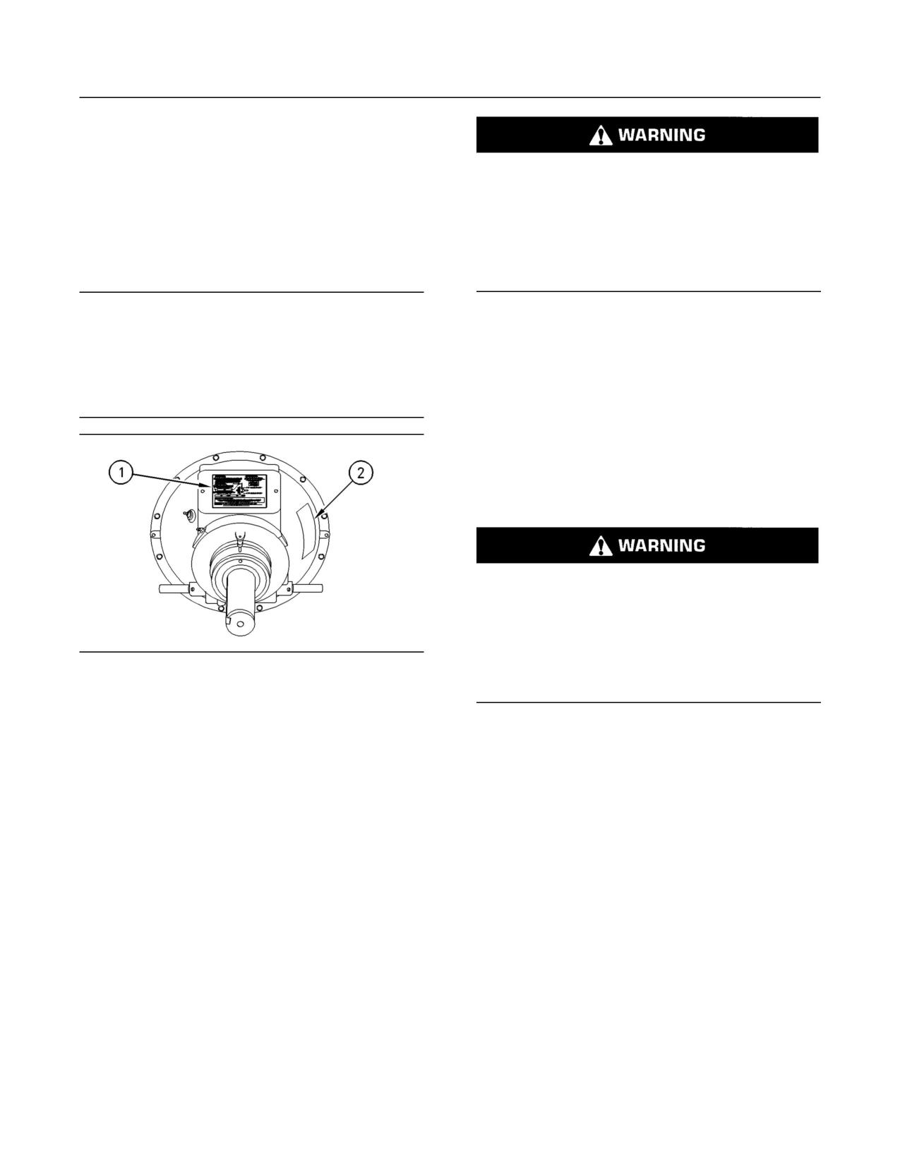
86
Maintenance Section
Power Take-Off Clutch - Check/Adjust/Lubricate
For more information about coolant analysis, see
your Caterpillar dealer.
Do not operate the engine with the Instruction
i00339617
Plate cover removed from the clutch. Personal
injury may result.
Power Take-Off Clutch -
If the clutch is damaged to the point of burst fail-
Check/Adjust/Lubricate
ure, expelled pieces can cause personal injury to
anyone in the immediate area. Proper safeguards
SMCS Code: 3055-036; 3055-086
must be followed to help prevent accidents.
NOTICE
New power take-offs should have the clutch adjust-
i01206548
ment checked before being placed into service. The
clutch adjustment should be checked again after the
Radiator - Clean
first ten hours of operation. New clutch plates have a
“wear in” period, and the clutch may require several
SMCS Code: 1353-070
adjustments until the new plates are “worn in”.
Note: Adjust the frequency of cleaning according to
the effects of the operating environment.
Inspect the radiator for these items: damaged fins,
corrosion, dirt, grease, insects, leaves, oil, and
other debris. Clean the radiator, if necessary.
Personal injury can result from air pressure.
Personal injury can result without following prop-
er procedure. When using pressure air, wear a pro-
tective face shield and protective clothing.
g00108044
Illustration 44
Maximum air pressure at the nozzle must be less
(1) Typical instruction plate for the clutch. (2) Typical serial number
than 205 kPa (30 psi) for cleaning purposes.
plate for the clutch.
The clutch adjustment should be checked regularly
Pressurized air is the preferred method for removing
after “wear in”. Heavy-duty applications which
loose debris. Direct the air in the opposite direction
have engagements that are frequent and relatively
of the fan’s air flow. Hold the nozzle approximately
long periods of clutch slippage require more
6 mm (0.25 inch) away from the fins. Slowly move
frequent adjustment than light-duty applications.
the air nozzle in a direction that is parallel with the
The operating torque should be measured in order
tubes. This will remove debris that is between the
to determine if a clutch adjustment is required.
tubes.
Refer to the OEM information and instruction plate
Pressurized water may also be used for cleaning.
(1) for instructions on the following items: lubrication,
The maximum water pressure for cleaning purposes
adjustment, and other service recommendations.
must be less than 275 kPa (40 psi). Use pressurized
Perform the maintenance that is specified on the
water in order to soften mud. Clean the core from
instruction plate.
both sides.
Use a degreaser and steam for removal of oil and
grease. Clean both sides of the core. Wash the core
with detergent and hot water. Thoroughly rinse the
core with clean water.
87
Maintenance Section
Starting Motor - Inspect
After cleaning, start the engine and accelerate the
engine to high idle rpm. This will help in the removal
NOTICE
of debris and drying of the core. Stop the engine.
Turbocharger bearing failures can cause large quan-
Use a light bulb behind the core in order to inspect
tities of oil to enter the air inlet and exhaust systems.
the core for cleanliness. Repeat the cleaning, if
Loss of engine lubricant can result in serious engine
necessary.
damage.
Inspect the fins for damage. Bent fins may be
Minor leakage of a turbocharger housing under ex-
opened with a “comb”. Inspect these items for
tended low idle operation should not cause problems
good condition: welds, mounting brackets, air lines,
as long as a turbocharger bearing failure has not oc-
connections, clamps, and seals. Make repairs, if
curred.
necessary.
When a turbocharger bearing failure is accompanied
For more detailed information on cleaning and
by a significant engine performance loss (exhaust
inspection, see Special Publication, SEBD0518,
smoke or engine rpm up at no load), do not continue
“Know Your Cooling System”.
engine operation until the turbocharger is repaired or
replaced.
i00651416
An inspection of the turbocharger can minimize
Starting Motor - Inspect
unscheduled downtime. An inspection of the
turbocharger can also reduce the chance for
SMCS Code: 1451-040; 1453-040
potential damage to other engine parts.
Caterpillar Inc. recommends a scheduled inspection
Note: Turbocharger components require precision
of the starting motor. If the starting motor fails, the
clearances. The turbocharger cartridge must
engine may not start in an emergency situation.
be balanced due to high rpm. Severe Service
Applications can accelerate component wear.
Check the starting motor for proper operation.
Severe Service Applications require more frequent
Check the electrical connections and clean the
inspections of the cartridge.
electrical connections. Refer to the Service Manual
for more information on the checking procedure and
for specifications or consult your Caterpillar dealer
Removal and Installation
for assistance.
For options regarding the removal, installation,
repair and replacement, consult your Caterpillar
i00912946
dealer. Refer to the Service Manual for this engine
for the procedure and specifications.
Turbocharger - Inspect
SMCS Code: 1052-040
Cleaning and Inspecting
Periodic inspection and cleaning is recommended
1. Remove the exhaust outlet piping and remove
for the turbocharger compressor housing (inlet
the air inlet piping from the turbocharger. Visually
side). Any fumes from the crankcase are filtered
inspect the piping for the presence of oil.
through the air inlet system. Therefore, by-products
from oil and from combustion can collect in the
2. Turn the compressor wheel and the turbine
turbocharger compressor housing. Over time, this
wheel by hand. The assembly should turn freely.
buildup can contribute to loss of engine power,
Inspect the compressor wheel and the turbine
increased black smoke and overall loss of engine
wheel for contact with the turbocharger housing.
efficiency.
There should not be any visible signs of contact
between the turbine wheel or compressor
If the turbocharger fails during engine operation,
wheel and the turbocharger housing. If there is
damage to the turbocharger compressor wheel
any indication of contact between the rotating
and/or to the engine may occur. Damage to
turbine wheel or the compressor wheel and the
the turbocharger compressor wheel can cause
turbocharger housing, the turbocharger must be
additional damage to the pistons, the valves, and
reconditioned.
the cylinder head.
88
Maintenance Section
Walk-Around Inspection
3.
Check the compressor wheel for cleanliness.
• Wipe all caps and plugs before the engine is
If only the blade side of the wheel is dirty,
serviced in order to reduce the chance of system
dirt and/or moisture is passing through the air
contamination.
filtering system. If oil is found only on the back
side of the wheel, there is a possibility of a failed
NOTICE
turbocharger oil seal.
For any type of leak (coolant, lube, or fuel) clean up the
fluid. If leaking is observed, find the source and correct
The presence of oil may be the result of extended
the leak. If leaking is suspected, check the fluid levels
engine operation at low idle. The presence of oil
more often than recommended until the leak is found
may also be the result of a restriction of the line
or fixed, or until the suspicion of a leak is proved to be
for the inlet air (plugged air filters), which causes
unwarranted.
the turbocharger to slobber.
4.
Use a dial indicator to check the end clearance
NOTICE
on the shaft. If the measured end play is greater
Accumulated grease and/or oil on an engine or deck is
than the Service Manual specifications, the
a fire hazard. Remove this debris with steam cleaning
turbocharger should be repaired or replaced.
or high pressure water.
An end play measurement that is less than the
minimum Service Manual specifications could
• Ensure that cooling lines are properly clamped
indicate carbon buildup on the turbine wheel.
and tight. Check for leaks. Check the condition
The turbocharger should be disassembled for
of all pipes.
cleaning and for inspection if the measured end
play is less than the minimum Service Manual
• Inspect the water pump for coolant leaks.
specifications.
Note: The water pump seal is lubricated by coolant
5.
Inspect the bore of the turbine housing for
in the cooling system. It is normal for a small amount
corrosion.
of leakage to occur as the engine cools down and
the parts contract.
6.
Clean the turbocharger housing with standard
shop solvents and a soft bristle brush.
Excessive coolant leakage may indicate the need
to replace the water pump seal. For the removal
7.
Fasten the air inlet piping and the exhaust outlet
of water pump and the installation of water pump
piping to the turbocharger housing.
and/or seals, refer to the Service Manual for the
engine or consult your Caterpillar dealer.
i00632301
• Inspect the lubrication system for leaks at the
Walk-Around Inspection
front crankshaft seal, the rear crankshaft seal, the
oil pan, the oil filters and the valve cover.
SMCS Code: 1000-040
Inspect the fuel system for leaks. Look for loose
•
fuel line clamps.
Inspect the Engine for Leaks and
for Loose Connections
• Inspect the piping for the air inlet system and the
elbows for cracks and for loose clamps.
A walk-around inspection should only take a few
minutes. When the time is taken to perform these
• Inspect the alternator belt and the accessory
checks, costly repairs and accidents can be
drive belts for cracks, breaks or other damage.
avoided.
Belts for multiple groove pulleys must be replaced
For maximum engine service life, make a thorough
as matched sets. If only one belt is replaced, the
inspection of the engine compartment before
belt will carry more load than the belts that are
starting the engine. Look for items such as oil leaks
not replaced. The older belts are stretched. The
or coolant leaks, loose bolts, worn belts, loose
additional load on the new belt could cause the
connections and trash buildup. Make repairs, as
belt to break.
needed:
•
Drain the water and the sediment from fuel tanks
• The guards must be in the proper place. Repair
on a daily basis in order to ensure that only clean
damaged guards or replace missing guards.
fuel enters the fuel system.
89
Maintenance Section
Water Pump - Inspect
• Inspect the wiring and the wiring harnesses for
loose connections and for worn wires or frayed
wires.
• Inspect the ground strap for a good connection
and for good condition.
• Inspect the engine-to-frame ground strap for a
good connection and for good condition.
• Disconnect any battery chargers that are not
protected against the current drain of the starting
motor. Check the condition and the electrolyte
level of the batteries, unless the engine is
equipped with a maintenance free battery.
• Check the condition of the gauges. Replace
any gauges which are cracked or can not be
calibrated.
i01057943
Water Pump - Inspect
SMCS Code: 1361-040; 1361
A failed water pump might cause severe engine
overheating problems that could result in the
following conditions:
• Cracks in the cylinder head
• A piston seizure
• Other potential damage to the engine
Visually inspect the water pump for leaks. If any
leaking is observed, replace the water pump
seal or the water pump assembly. Refer to the
Service Manual for the disassembly and assembly
procedure.
Note: Refer to the Service Manual or consult your
Caterpillar dealer if any repair is needed or any
replacement is needed.
90
Reference Information Section
Customer Service
Central America and Caribbean
Reference Information
Caterpillar Americas Co.
Section
15550 NW 59th Avenue
Miami Lakes, FL 33014
USA
Phone: 305-816-3306
Customer Service
Fax: 305-816-3307
Mexico
i00790127
Grupo Financiero Caterpillar Mexico, S.A. de
C.V.
Customer Assistance
Primer piso del Arco Oriente de Arco Bosques
Corporativa,
SMCS Code: 1000
Bosques del Alisos 45A
Bosques de Las Lomas
USA and Canada
Mexico, D.F. 05120
Phone (from within Mexico): 915-258-1515
When a problem arises concerning the operation of
Fax (from within Mexico): 915-258-1530
an engine or concerning the service of an engine,
Phone (from within USA): 011-525-258-1515
the problem will normally be managed by the dealer
Fax (from within USA): 011-525-258-1530
in your area.
Ecuador, Colombia, Venezuela, Guyana, and
Your satisfaction is a primary concern to Caterpillar
Suriname
and to Caterpillar dealers. If you have a problem
Caterpillar Americas Co.
that has not been handled to your complete
15550 NW 59th Avenue
satisfaction, follow these steps:
Miami Lakes, FL 33014
USA
1. Discuss your problem with a manager from the
Phone: 305-816-3316
dealership.
Fax: 305-816-3317
2. If your problem cannot be resolved at the dealer
Peru, Chile, and Bolivia
level without additional assistance, use the
Caterpillar Americas Co.
phone number that is listed below to talk with a
Edificio Centro Santa Maria
Field Service Coordinator:
Av. Los Conquistadores 1700
Piso 14, Oficina A
1-800-447-4986
Santiago, Chile
Phone: 011-562-366-5100
The normal hours are from 8:00 to 4:30 Monday
Fax: 011-562-366-5125
through Friday Central Standard Time.
Brazil, Argentina, Paraguay, and Uruguay
3. If your needs have not been met still, submit the
Caterpillar Americas Co.
matter in writing to the following address:
Birmann II
Rua Aleandre Dumas, 1.711-9.0
Caterpillar Inc.
Chac., Sto. Antonio
Manager, Customer Service, Engine Division
04717-004-Sao Paulo, SP
Mossville Bldg A
Phone: 55-11-5180-2000
P.O. Box 600
Fax: 55-11-5182-9694
Peoria, Illinois 61552-0600
Europe, Africa, and Middle East
Please keep in mind: probably, your problem will
Caterpillar Overseas S.A.
ultimately be solved at the dealership, using the
76 Route de Frontenex
dealership’s facilities, equipment, and personnel.
P.O. Box 6000
Therefore, follow the steps in sequence when a
1211 Geneva 6
problem is experienced.
Switzerland
Phone: 22-849-4444
Outside of the USA and of Canada
Fax: 22-849-4544
If a problem arises outside the USA and outside
Canada, and if the problem cannot be resolved at
the dealer level, consult the appropriate Caterpillar
office.
91
Reference Information Section
Customer Service
Far East
i01028392
Caterpillar Asia Pte. Ltd.
Ordering Replacement Parts
7 Tractor Road
Jurong, Singapore 627968
SMCS Code: 7567
Republic of Singapore
Phone: 65-662-8333
Fax: 65-662-8302
China
When replacement parts are required for this
Caterpillar China Ltd.
product Caterpillar recommends using Caterpillar
37/F, The Lee Gardens
replacement parts or parts with equivalent spec-
33 Hysan Avenue
ifications including, but not limited to, physical
Causeway Bay, Hong Kong
dimensions, type, strength and material.
China
Phone: 852-2848-0333
Failure to heed this warning can lead to prema-
Fax: 852-2848-0440
ture failures, product damage, personal injury or
death.
Japan
Shin Caterpillar Mitsubishi Ltd.
Quality Caterpillar replacement parts are available
Setagaya Business Square Tower
from Caterpillar dealers throughout the world.
10-1, Yoga 4-chome
Caterpillar dealers’ parts inventories are up-to-date.
Setagaya, Tokyo
The parts stocks include all of the parts that are
Japan
normally needed to protect your Caterpillar engine
Phone: 81-3-5717-1121
investment.
Fax: 81-3-5717-1177
When you order parts, please specify the following
Japan
information:
Caterpillar Power Systems, Inc.
Japan Branch Sanno Grand Bldg.
2-14-2 Nagatacho
• Part number
Chiyoda-ku, Tokyo, 100
Japan
• Part name
Phone: 81-335-93-3237
Fax: 81-335-93-3238
• Quantity
If there is a question concerning the part number,
Australia and New Zealand
please provide your dealer with a complete
Caterpillar of Australia Ltd.
description of the needed item.
1 Caterpillar Drive
Private Mail Bag 4
When a Caterpillar engine requires maintenance
Tullamarine, Victoria 3043
and/or repair, provide the dealer with all the
Australia
information that is stamped on the Information Plate.
Phone: 03-9339-9333
This information is described in this Operation and
Fax: 03-9335-3366
Maintenance Manual (Product Information Section).
Discuss the problem with the dealer. Inform the
dealer about the conditions of the problem and
the nature of the problem. Inform the dealer about
when the problem occurs. This will help the dealer
in troubleshooting the problem and solving the
problem faster.
92
Reference Information Section
Reference Materials
Reference Materials
Coolants
Special Publication, SEBD0970, “Coolant and
•
i01370327
Your Engine”
Reference Material
• Special Publication, PEHP4036, “Data Sheet-
Extended Life Coolant”
SMCS Code: 1000
• Special Publication, SEBD0518, “Knowing Your
The following literature can be obtained through any
Cooling System”
Caterpillar dealer.
Special Publication, PEEP5027, “Label ELC
•
Lubricants
Radiator Label”
• Special Publication, PEHP7041, “Data Sheet
• Special Publication, PEHP7057, “S·O·S Coolant
- Caterpillar Diesel Engine Oils (DEO) (CG-4)
Analysis”
(International only)”
Miscellaneous
• Special Publication, PEHP1026, “Data Sheet
- Caterpillar Diesel Engine Oil (DEO) (CF-4)
• Service Manual, SENR1110, “3406C Industrial
(International only)”
Engine”
• Special Publication, PEHP1027, “Data Sheet -
• Special Publication, SEBU6251, “Caterpillar
Caterpillar Diesel Engine Oil (CD)”
Commercial Diesel Engine Fluids
Recommendations”
• Special Publication, PEHP8038, “Data Sheet
- Caterpillar Diesel Engine Oils (DEO) (CH-4)
• Special Publication, PECP6026, “One Safe
(North America and Australia)”
Source”
• Special Publication, PEWP9733, “Cat Fluids
• Special Publication, SEHS7654, “Alignment -
Selector Dial”
General Instructions”
• Special Publication, PEWP3014, “Cat Fluids
• Operation and Maintenance Manual, SEBU5898,
Selector Dial (International)”
“Cold Weather Recommendations”
• Special Publication, NEDG6022, “Data Sheet -
• Special Instruction, SMHS7001, “Assembly of Fan
Multipurpose Lithium Complex Grease (MPG)”
Drive Pulley Assemblies”
• Special Publication, PEHP0002, “Data Sheet
• Special Instruction, SEHS7633, “Battery Test
- Multipurpose Lithium Complex Grease with
Procedure”
Molybdenum (MPGM)”
• Special Instruction, SEHS7332, “Do Not Operate
• Special Publication, PEHP0017, “Data Sheet -
Tag”
Special Purpose Grease (SPG) Bearing Lubricant”
• Special Publication, SEBF8062, “Guideline for
• Special Publication, NEHP5621, “How To Select
Reusable Parts - Cleaning and Inspection of Air
The Right Grease For Any Job”
Filters”
• Special Publication, PEHP6001, “How To Take A
• Special Publication, SEBF8029, “Index of
Good Oil Sample”
Publications for Reusable Parts and Salvage
Operations”
• Special Publication, SEBD0640, “Oil and Your
Engine”
• Special Publication, LEBH9324, “Industrial
Application and Installation Guide”
• Special Publications, PEDP7036, “SOS Fluids
Analysis Cornerstone”
• Service Manual, REG1139F, “Service Manual
Contents Microfiche”
Fuels
Special Instruction, SEHS9031, “Storage
•
• Special Publication, SEBD0717, “Diesel Fuels and
Procedure for Caterpillar Products”
Your Engine”
93
Reference Information Section
Reference Materials
• Special Instruction, NENG2500, “Tools and Shop
The “American Petroleum Institute Publication No.
Products Guide”
1509” can be obtained from the following locations:
local technological society, local library, and local
• Specifications, SENR3130, “Torque Specifications”
college. If necessary, consult API at the following
address:
• Special Instruction, SEHS7292, “Using the
5P-4150 Nozzle Testing Group”
American Petroleum Institute
1220 L St. N.W.
• Special Instruction, SEHS8024, “Governor
Washington, DC, USA 20005
Adjusting Tool Group”
Telephone: (202) 682-8000
• Special Instruction, SEHS8094, “Using the Nozzle
The International Organization for Standardization
Puller Group”
(ISO) offers information and customer service
regarding international standards and standardizing
• Special Instruction, SEHS8622, “Using the FT-
activities. ISO can also supply information on the
1984 Air-To-Air Aftercooler Leak Test Group”
following subjects that are not controlled by ISO:
national standards, regional standards, regulations,
certification, and related activities. Consult the
Emissions Warranty
member of ISO in your country.
This engine may be Certified and this engine
International Organization for Standardization
may be covered by an Emissions Warranty. A
(ISO)
detailed explanation of the Emissions Warranty
1, rue de Varembé
that is applicable to Certified engines is found in
Case postale 56
Supplement, SEBU6981, “Federal Emissions Control
CH-1211 Genève 20
Warranty Information”. The Engine is Certified if
Switzerland
the engine has a special label that states that the
Telephone: +41 22 749 01 11
engine is certified. A Caterpillar dealer can also
Facsimile: +41 22 733 34 30
inform you if the engine is Certified.
E-mail: central@iso.ch
Web site: http://www.iso.ch
i01109461
European classifications are established by the
Additional Reference Material
Counseil International Des Machines a Combustion
(CIMAC) (International Council on Combustion
SMCS Code: 1000
Engines).
The “EMA Lubricating Oils Data Book” can
CIMAC Central Secretariat
be obtained from the following locations: local
Lyoner Strasse 18
technological society, local library, and local college.
60528 Frankfurt
If necessary, consult EMA at the following address:
Germany
Telephone: +49 69 6603 1567
Engine Manufacturers Associaton
Facsimile: +49 69 6603 1566
401 N. Michigan Ave.
Chicago, IL, USA 60611
i00912149
Telephone: (312) 644-6610 ext. 3626
Maintenance Records
The “Society of Automotive Engineers (SAE)
Specifications” can be found in your SAE handbook.
SMCS Code: 1000
This publication can also be obtained from the
following locations: local technological society, local
Caterpillar Inc. recommends the retention
library, and local college. If necessary, consult SAE
of accurate maintenance records. Accurate
at the following address:
maintenance records can be used for the following
purposes:
SAE International
400 Commonwealth Drive
• Determine operating costs.
Warrendale, PA, USA 15096-0001
Telephone: (724) 776-4841
• Establish maintenance schedules for other
engines that are operated in the same
environment.
94
Reference Information Section
Reference Materials
• Show compliance with the required maintenance
practices and maintenance intervals.
Maintenance records can be used for a variety of
other business decisions that are related to engine
maintenance.
Maintenance records are a key element of a
maintenance program that is well managed.
Accurate maintenance records can help your
Caterpillar dealer to fine tune the recommended
maintenance intervals in order to meet the specific
operating situation. This should result in a lower
engine operating cost.
Records should be kept for the following items:
Fuel Consumption - A record of fuel consumption
is essential in order to determine when the load
sensitive components should be inspected or
repaired. Fuel consumption also determines
overhaul intervals.
Service Hours - A record of service hours is
essential to determine when the speed sensitive
components should be inspected or repaired.
Documents - These items should be easy to obtain,
and these items should be kept in the engine
history file. All of the documents should show this
information: date, service hours, fuel consumption,
unit number, and engine serial number. The
following types of documents should be kept as
proof of maintenance or repair for warranty:
Keep the following types of documents as proof of
maintenance for warranty. Also, keep these types of
documents as proof of repair for warranty:
• Dealer work orders and itemized bills
• Owner’s repair costs
• Owner’s receipts
• Maintenance log

95
Reference Information Section
Reference Materials
i01176304
Maintenance Log
SMCS Code: 1000
Table 36
Engine Model
Customer Identifier
Serial Number
Arrangement Number
Service
Quantity
Service Item
Date
Authorization
Hours
Of Fuel
96
Index Section
Index
A
Cooling System Coolant (ELC) - Change
67
Drain
67
Additional Reference Material
93
Fill
68
After Starting Engine
27
Flush
67
After Stopping Engine
31
Cooling System Coolant Extender (ELC) - Add
68
Aftercooler Core - Clean/Test (Air-To-Air
Cooling System Coolant Level - Check
68
Aftercooler)
60
Cooling System Specifications
46
Aftermarket Oil Additives
41
Cooling System Supplemental Coolant Additive
Air Compressor - Inspect
60
(SCA) - Test/Add
69
Air Starting
27
Add the SCA, If Necessary
70
Air Starting Motor Lubricator Oil Level - Check (If
S·O·S Coolant Analysis
69
Equipped)
61
Test for SCA Concentration
69
Oiler Feed Adjustment
61
Cooling System Water Temperature Regulator -
Air Tank Moisture and Sediment - Drain (If
Replace
70
Equipped)
61
Crankshaft Vibration Damper - Inspect
71
Alternator - Inspect
62
Rubber Damper
71
Alternator Belt - Inspect/Adjust/Replace
62
Visconic Damper
71
Adjustment
62
Crushing Prevention and Cutting Prevention
12
Inspection
62
Customer Assistance
90
Replacement
63
Outside of the USA and of Canada
90
USA and Canada
90
Customer Service
90
B
Battery - Replace
63
D
Battery Charger - Check
64
Checking After Stopping
65
Diesel Engine Antifreeze/Coolant (DEAC)
52
Checking Before Start-Up
64
Driven Equipment - Check
71
Battery Electrolyte Level - Check
63
Battery or Battery Cable - Disconnect
64
Before Starting Engine
12, 24
E
Burn Prevention
10
Batteries
10
Emergency Stopping
30
Coolant
10
Emergency Stop Button
30
Oils
10
Emissions Certification Film
18
Engaging the Driven Equipment
29
Engine - Clean
72
C
Engine Air Cleaner Element (Single Element) -
Inspect/Replace
72
Cold Weather Lubricants
41
Engine Air Cleaner Service Indicator - Inspect
73
Cold Weather Operation
32
Test the Service Indicator
73
Cold Weather Starting
25
Engine Crankcase Breather - Clean
73
Commercial Heavy-Duty Coolant/Antifreeze and
Engine Description
15
SCA
53
Engine Cooling and Lubrication
16
Conventional Coolant/Antifreeze Cooling System
Engine Information
15
Maintenance
55
Engine Specifications
16
Cleaning the System of Heavy-Duty
Engine Features and Controls
21
Coolant/Antifreeze
57
Engine Identification
17
Cooling Systems with Larger Capacities
56
Engine Lifting
19
Coolant Recommendations
48
Engine Lifting with a Fuel Tank
19
Cooling System Coolant (DEAC) - Change
65
Engine Lifting and Storage
19
Cooling Systems with Heavy Deposits or
Engine Mounts - Inspect
74
Plugging
66
Engine Oil
37
Drain
65
Caterpillar Diesel Engine Oil
37
Fill
66
Commercial Oils
38
Flush
65
Total Base Number (TBN) and Fuel Sulfur Levels
for Direct Injection (DI) Diesel Engines
39
97
Index Section
Engine Oil and Filter - Change
75
Fuel Tank Water and Sediment - Drain
81
Drain the Engine Oil
75
Drain the Water and the Sediment
81
Fill the Engine Crankcase
76
Fuel Storage Tanks
81
Replace the Oil Filter
76
Fuel Tank
81
Engine Oil Level - Check
74
Engine Oil Sample - Obtain
74
Obtain the Sample and the Analysis
75
G
Engine Operation
28
Engine Protective Devices - Check
77
Gauges and Indicators
20
Visual Inspection
77
General Coolant Information
46
Engine Shutoffs and Engine Alarms
21
Additives
47
Alarms
21
Glycol
47
Shutoffs
21
Water
46
Testing the Shutoff and Alarm System
22
General Hazard Information
7
Engine Starting
13, 24
Asbestos Information
9
Ether
13
Containing Fluid Spillage
9
Engine Stopping
13, 30
Dispose of Waste Properly
10
Engine Storage
19
Fluid Penetration
9
Engine Valve Lash - Inspect/Adjust
77
Pressure Air and Water
8
Engine Valve Rotators - Inspect
77
General Torque Information
34
Engine Warm-up
28
Extended Life Coolant (ELC)
49
Extended Life Coolant (ELC) Cooling System
H
Maintenance
50
Caterpillar ELC Extender
50
Hoses and Clamps - Inspect/Replace
82
Changing to Caterpillar ELC
51
Replace the Hoses and the Clamps
82
Commercial ELC
52
ELC Cooling System Cleaning
51
ELC Cooling System Contamination
52
I
Proper additions to the Extended Life Coolant .. 50
Important Safety Information
2
Information Plate
17
F
Fan Drive Bearing - Lubricate
78
L
Fire Prevention and Explosion Prevention
10
Ether
12
Lubricant Information
37
Fire Extinguisher
12
API Oils
37
Foreword
5
Engine Manufacturers Association (EMA) Oils .. 37
California Proposition 65 Warning
5
General Information
37
Literature Information
4
Lubricant Specifications
37
Maintenance
4
Lubricating Grease
41
Maintenance Intervals
4
Caterpillar Premium Grease (CPG)
43
Operation
4
Multipurpose Greases
42
Overhaul
4
Special Purpose Grease (SPG)
42
Safety
4
Fuel and the Effect from Cold Weather
32
Fuel Conservation Practices
29
M
Fuel Control Linkage - Check/Lubricate
78
Fuel Injection Nozzles - Test/Exchange
78
Maintenance Interval Schedule
59
Removal and Installation of the Fuel Injection
Maintenance Log
95
Nozzles
79
Maintenance Records
93
Fuel Ratio Control - Inspect/Adjust
79
Maintenance Section
34
Fuel Recommendations
44
Manual Stop Procedure
30
Fuel Related Components in Cold Weather
33
Model View Illustrations
14
Fuel Filters
33
Model Views
14
Fuel Heaters
33
Mounting and Dismounting
12
Fuel Tanks
33
Fuel Specifications
44
Fuel System - Prime
79
Fuel System Primary Filter - Clean/Replace
80
98
Index Section
O
T
Operation Section
19
Table of Contents
3
Ordering Replacement Parts
91
Torque Specifications
34
Overhaul Considerations
83
Turbocharger - Inspect
87
Oil Consumption as an Overhaul Indicator
83
Cleaning and Inspecting
87
Overhaul Recommendation
83
Removal and Installation
87
P
W
Power Take-Off Clutch - Check/Adjust/Lubricate...
86
Walk-Around Inspection
88
Product Identification Information
17
Inspect the Engine for Leaks and for Loose
Product Information Section
14
Connections
88
Water Pump - Inspect
89
Water/Supplemental Coolant Additive (SCA)
53
R
Cooling Systems with Larger Capacities
54
Radiator - Clean
86
Radiator Restrictions
32
Re-refined Base Stock Oils
40
Reference Information Section
90
Reference Material
92
Coolants
92
Emissions Warranty
93
Fuels
92
Lubricants
92
Miscellaneous
92
Reference Materials
92
Reference Numbers
17
Record for Reference
17
Refill Capacities
58
Cooling System
58
Lubrication System
58
S
S·O·S Coolant Analysis
48
New Systems, Refilled Systems, and Converted
Systems
49
Recommended Interval for S·O·S Coolant
Sample
49
S·O·S Coolant Analysis (Level 1)
49
S·O·S Coolant Analysis (Level 2)
49
S·O·S Oil Analysis
43
Safety Section
6
Safety Signs and Labels
6
Serial Number Plate
17
Standard Torque for Constant Torque Hose
Clamps
35
Standard Torque for Inch Fasteners
34
Standard Torque for Metric Fasteners
35
Standard Torque for Worm Drive Band Hose
Clamps
35
Starting Motor - Inspect
87
Starting the Engine
25
Starting with Jump Start Cables
26
Supplemental Coolant Additive (SCA)
52
Synthetic Base Stock Oils
40
Product and Dealer Information
Note: For product identification plate locations, see the section “Product Identification Information” in the
Operation and Maintenance Manual.
Delivery Date:
Product Information
Model:
Product Identification Number:
Engine Serial Number:
Transmission Serial Number:
Generator Serial Number:
Attachment Serial Numbers:
Attachment Information:
Customer Equipment Number:
Dealer Equipment Number:
Dealer Information
Name:
Branch:
Address:
Dealer Contact
Phone Number
Hours
Sales:
Parts:
Service: