CAT. C15 and C18 Engines. Operation and Maintenance Manual (2014)
SEBU8598-09
December 2014
Operation and
Maintenance
Manual
C15 and C18 Engines
BDN 1-Up (C15 Engine)
LDN 1-Up (C18 Engine)
i05296198
Important Safety Information
Most accidents that involve product operation, maintenance and repair are caused by failure to observe
basic safety rules or precautions. An accident can often be avoided by recognizing potentially hazardous
situations before an accident occurs. A person must be alert to potential hazards, including human factors
that can affect safety. This person should also have the necessary training, skills and tools to perform these
functions properly.
Improper operation, lubrication, maintenance or repair of this product can be dangerous and could
result in injury or death.
Do not operate or perform any lubrication, maintenance or repair on this product, until you verify
that you are authorized to perform this work, and have read and understood the operation,
lubrication, maintenance and repair information.
Safety precautions and warnings are provided in this manual and on the product. If these hazard warnings
are not heeded, bodily injury or death could occur to you or to other persons.
The hazards are identified by the “Safety Alert Symbol” and followed by a “Signal Word” such as
“DANGER”, “WARNING” or “CAUTION”. The Safety Alert “WARNING” label is shown below.
The meaning of this safety alert symbol is as follows:
Attention! Become Alert! Your Safety is Involved.
The message that appears under the warning explains the hazard and can be either written or pictorially
presented.
A non-exhaustive list of operations that may cause product damage are identified by “NOTICE” labels on
the product and in this publication.
Caterpillar cannot anticipate every possible circumstance that might involve a potential hazard.
The warnings in this publication and on the product are, therefore, not all inclusive. You must not
use this product in any manner different from that considered by this manual without first satisfying
yourself that you have considered all safety rules and precautions applicable to the operation of the
product in the location of use, including site-specific rules and precautions applicable to the
worksite. If a tool, procedure, work method or operating technique that is not specifically
recommended by Caterpillar is used, you must satisfy yourself that it is safe for you and for others.
You should also ensure that you are authorized to perform this work, and that the product will not be
damaged or become unsafe by the operation, lubrication, maintenance or repair procedures that
you intend to use.
The information, specifications, and illustrations in this publication are on the basis of information that was
available at the time that the publication was written. The specifications, torques, pressures,
measurements, adjustments, illustrations, and other items can change at any time. These changes can
affect the service that is given to the product. Obtain the complete and most current information before you
start any job. Cat dealers have the most current information available.
When replacement parts are required for this
product Caterpillar recommends using Cat re-
placement parts.
Failure to follow this warning may lead to pre-
mature failures, product damage, personal in-
jury or death.
In the United States, the maintenance, replacement, or repair of the emission control devices and
systems may be performed by any repair establishment or individual of the owner's choosing.
SEBU8598
3
Table of Contents
Table of Contents
Refill Capacities
45
Maintenance Recommendations
51
Foreword
4
Maintenance Interval Schedule (C15 Engines)54
Safety Section
Maintenance Interval Schedule (C15 Engines
Safety Messages
5
With Ratings Greater Than 579 hp)
55
General Hazard Information
7
Maintenance Interval Schedule (C18 Engines
With Ratings Greater Than 760 HP)
56
Burn Prevention
10
Maintenance Interval Schedule (C18 Engines)58
Fire Prevention and Explosion Prevention
11
Warranty Section
Crushing Prevention and Cutting Prevention . 13
Warranty Information
94
Mounting and Dismounting
13
Reference Information Section
Before Starting Engine
13
Engine Ratings
95
Engine Starting
14
Customer Service
96
Engine Stopping
14
Reference Materials
98
Electrical System
14
Engine Electronics
15
Index Section
Index
102
Product Information Section
General Information
16
Product Identification Information
20
Operation Section
Lifting and Storage
23
Features and Controls
27
Engine Diagnostics
32
Engine Starting
33
Engine Operation
37
Cold Weather Operation
42
Engine Stopping
44
Maintenance Section
4
SEBU8598
Foreword
Foreword
Recommended service should be performed at the
appropriate intervals as indicated in the Maintenance
Interval Schedule. The actual operating environment
of the engine also governs the Maintenance Interval
Literature Information
Schedule. Therefore, under extremely severe, dusty,
This manual contains safety, operation instructions,
wet or freezing cold operating conditions, more
lubrication and maintenance information. This manual
frequent lubrication and maintenance than is
should be stored in or near the engine area in a
specified in the Maintenance Interval Schedule may
literature holder or literature storage area. Read,
be necessary.
study and keep it with the literature and engine
The maintenance schedule items are organized for a
information.
preventive maintenance management program. If the
English is the primary language for all Cat
preventive maintenance program is followed, a
publications. The English used facilitates translation
periodic tune-up is not required. The implementation
and consistency in electronic media delivery.
of a preventive maintenance management program
should minimize operating costs through cost
Some photographs or illustrations in this manual
avoidances resulting from reductions in unscheduled
show details or attachments that may be different
downtime and failures.
from your engine. Guards and covers may have been
removed for illustrative purposes. Continuing
Maintenance Intervals
improvement and advancement of product design
may have caused changes to your engine which are
Perform maintenance on items at multiples of the
not included in this manual. Whenever a question
original requirement. Each level and/or individual
arises regarding your engine, or this manual, please
items in each level should be shifted ahead or back
consult with your Cat dealer for the latest available
depending upon your specific maintenance practices,
information.
operation and application. We recommend that the
maintenance schedules be reproduced and displayed
near the engine as a convenient reminder. We also
Safety
recommend that a maintenance record be maintained
as part of the engine's permanent record.
This safety section lists basic safety precautions. In
addition, this section identifies hazardous, warning
See the section in the Operation and Maintenance
situations. Read and understand the basic
Manual, “Maintenance Records” for information
precautions listed in the safety section before
regarding documents that are generally accepted as
operating or performing lubrication, maintenance and
proof of maintenance or repair. Your authorized Cat
repair on this product.
dealer can assist you in adjusting your maintenance
schedule to meet the needs of your operating
Operation
environment.
Operating techniques outlined in this manual are
Overhaul
basic. They assist with developing the skills and
techniques required to operate the engine more
Major engine overhaul details are not covered in the
efficiently and economically. Skill and techniques
Operation and Maintenance Manual except for the
develop as the operator gains knowledge of the
interval and the maintenance items in that interval.
engine and its capabilities.
Major repairs are best left to trained personnel or an
authorized Cat dealer. Your Cat dealer offers a variety
The operation section is a reference for operators.
of options regarding overhaul programs. If you
Photographs and illustrations guide the operator
experience a major engine failure, there are also
through procedures of inspecting, starting, operating
numerous after failure overhaul options available
and stopping the engine. This section also includes a
from your Cat dealer. Consult with your dealer for
discussion of electronic diagnostic information.
information regarding these options.
Maintenance
California Proposition 65 Warning
The maintenance section is a guide to engine care.
Diesel engine exhaust and some of its constituents
The illustrated, step-by-step instructions are grouped
are known to the State of California to cause cancer,
by fuel consumption, service hours and/or calendar
birth defects, and other reproductive harm.
time maintenance intervals. Items in the maintenance
schedule are referenced to detailed instructions that
Battery posts, terminals and related accessories
follow.
contain lead and lead compounds. Wash hands after
Use fuel consumption or service hours to determine
handling.
intervals. Calendar intervals shown (daily, annually,
etc.) may be used instead of service meter intervals if
they provide more convenient schedules and
approximate the indicated service meter reading.
SEBU8598
5
Safety Section
Safety Messages
Safety Section
i04085252
Safety Messages
SMCS Code: 1000; 7405
There may be several specific safety messages on
your engine. The exact location and a description of
the safety messages are reviewed in this section.
Become familiar with all safety messages.
Ensure that all of the safety messages are legible.
Clean the safety messages or replace the safety
messages if the words cannot be read or if the
illustrations are not visible. Use a cloth, water, and
soap to clean the safety messages. Do not use
solvents, gasoline, or other harsh chemicals.
Solvents, gasoline, or harsh chemicals could loosen
the adhesive that secures the safety messages. The
safety messages that are loosened could drop off the
engine.
Replace any safety message that is damaged or
missing. If a safety message is attached to a part of
the engine that is replaced, install a new safety
message on the replacement part. Your Caterpillar
dealer can provide new safety messages.
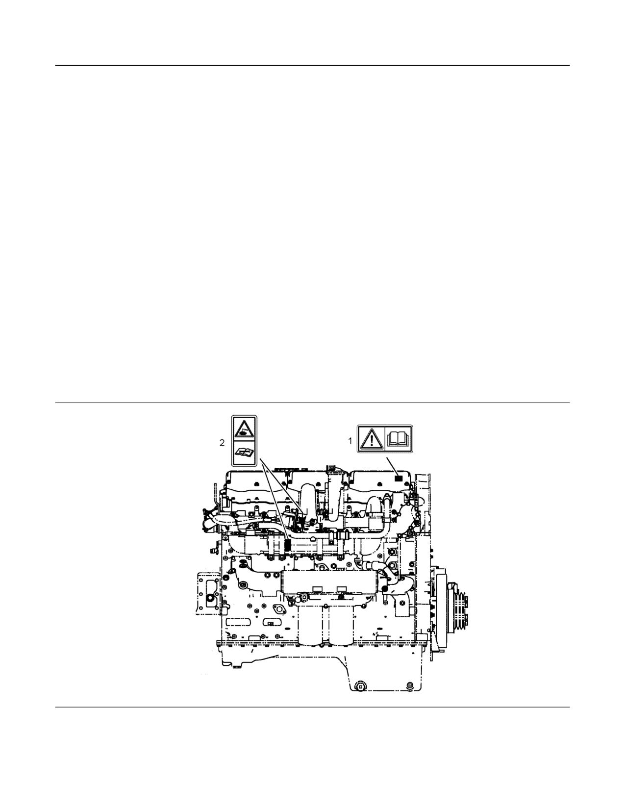
Illustration 1
g02295113
View of the right side of a typical C15 or C18 Industrial Engine
6
SEBU8598
Safety Section
Safety Messages
Universal Warning (1)
Sulfuric Acid Burn (2)
Illustration 2
g01370904
One safety message is located on the left side of the
valve cover. One safety message is located on the
right side of the valve cover.
Illustration 3
g01382725
Do not operate or work on this equipment unless
One safety message for sulfuric acid burn is located
you have read and understand the instructions
on top of the exhaust cooler. One safety message for
and warnings in the Operation and Maintenance
sulfuric acid burn is located on the right side of the
Manual. Failure to follow the instructions or heed
exhaust cooler.
the warnings could result in injury or death. Con-
tact any Caterpillar dealer for replacement man-
uals. Proper care is your responsibility.
Sulfuric Acid Burn Hazard may cause serious per-
sonal injury or death.
The exhaust gas cooler may contain a small
amount of sulfuric acid. The use of fuel with sulfur
levels greater than 15 ppm may increase the
amount of sulfuric acid formed. The sulfuric acid
may spill from the cooler during service of the en-
gine. The sulfuric acid will burn the eyes, skin and
clothing on contact. Always wear the appropriate
personal protective equipment (PPE) that is noted
on a material safety data sheet (MSDS) for sulfuric
acid. Always follow the directions for first aid that
are noted on a material safety data sheet (MSDS)
for sulfuric acid.
SEBU8598
7
Safety Section
General Hazard Information
i05334609
General Hazard Information
SMCS Code: 1000; 4450; 7405
Illustration 5
g00702020
• Wear a hard hat, protective glasses, and other
protective equipment, as required.
• When work is performed around an engine that is
Illustration 4
g00104545
operating, wear protective devices for ears in order
to help prevent damage to hearing.
Attach a “Do Not Operate” warning tag to the start
switch or controls before the engine is serviced or
• Do not wear loose clothing or jewelry that can snag
repaired. These warning tags (Special Instruction,
on controls or on other parts of the engine.
SEHS7332) are available from your Cat dealer.
Attach the warning tags to the engine and to each
• Ensure that all protective guards and all covers are
operator control station. When appropriate,
secured in place on the engine.
disconnect the starting controls.
• Never put maintenance fluids into glass
Do not allow unauthorized personnel on the engine,
containers. Glass containers can break.
or around the engine when the engine is being
serviced.
• Use all cleaning solutions with care.
Cautiously remove the following parts. To help
• Report all necessary repairs.
prevent spraying or splashing of pressurized fluids,
hold a rag over the part that is being removed.
Unless other instructions are provided, perform
the maintenance under the following conditions:
• Filler caps
• Grease fittings
• Pressure taps
• Breathers
• Drain plugs
Use caution when cover plates are removed.
Gradually loosen, but do not remove the last two bolts
or nuts that are located at opposite ends of the cover
plate or the device. Before removing the last two bolts
or nuts, pry the cover loose in order to relieve any
spring pressure or other pressure.
8
SEBU8598
Safety Section
General Hazard Information
• The engine is stopped. Ensure that the engine
Fluid Penetration
cannot be started.
• The protective locks or the controls are in the
applied position.
• Disconnect the batteries when maintenance is
performed or when the electrical system is
serviced. Disconnect the battery ground leads.
Tape the leads in order to help prevent sparks.
• When starting a new engine, make provisions to
stop the engine if an overspeed occurs. If an
engine has not been started since service has
been performed, make provisions to stop the
engine if an overspeed occurs. Shutting down the
engine may be accomplished by shutting off the
fuel supply and/or the air supply to the engine.
Illustration 6
g00687600
• Do not attempt any repairs that are not
Always use a board or cardboard when you check for
understood. Use the proper tools. Replace any
a leak. Leaking fluid that is under pressure can
equipment that is damaged or repair the
penetrate body tissue. Fluid penetration can cause
equipment.
serious injury and possible death. A pin hole leak can
cause severe injury. If fluid is injected into your skin,
• Start the engine with the operator controls. Never
you must get treatment immediately. Seek treatment
short across the starting motor terminals or the
from a doctor that is familiar with this type of injury.
batteries. This method of starting the engine could
bypass the engine neutral start system and/or the
Containing Fluid Spillage
electrical system could be damaged.
NOTICE
Pressurized Air and Water
Care must be taken to ensure that fluids are con-
tained during performance of inspection, mainte-
Pressurized air and/or water can cause debris and/or
nance, testing, adjusting, and repair of the product.
hot water to be blown out which could result in
Be prepared to collect the fluid with suitable contain-
personal injury.
ers before opening any compartment or disassem-
The maximum air pressure for cleaning purposes
bling any component containing fluids.
must be reduced to 205 kPa (30 psi) when the air
nozzle is deadheaded and used with effective chip
Refer to Special Publication, NENG2500, “Cat Dealer
guarding (if applicable) and personal protective
Service Tool Catalog” or refer to Special Publication,
PECJ0003, “Cat Shop Supplies and Tools Catalog”
equipment. The maximum water pressure for
for tools and supplies suitable to collect and contain
cleaning purposes must be below 275 kPa (40 psi).
fluids on Cat products.
When pressurized air and/or pressurized water is
used for cleaning, wear protective clothing, protective
Dispose of all fluids according to local regulations and
shoes, and eye protection. Eye protection includes
mandates.
goggles or a protective face shield. Always wear eye
protection for cleaning the cooling system.
Avoid direct spraying of water on electrical
connectors, connections, and components. When
using air for cleaning, allow the machine to cool to
reduce the possibility of fine debris igniting when
redeposited on hot surfaces.
SEBU8598
9
Safety Section
General Hazard Information
Static Electricity Hazard when
Ensure that all of the clamps, the guards, and the
heat shields are installed correctly. Correct installation
Fueling with Ultra-low Sulfur Diesel
of these components will help to prevent these
Fuel
effects: vibration, rubbing against other parts and
excessive heat during operation.
The removal of sulfur and other compounds in ultra-
low sulfur diesel fuel (ULSD fuel) decreases the
Inhalation
conductivity of ULSD and increases the ability of
ULSD to store static charge. Refineries may have
treated the fuel with a static dissipating additive.
Many factors can reduce the effectiveness of the
additive over time. Static charges can build up in
ULSD fuel while the fuel is flowing through fuel
delivery systems. Static electricity discharge when
combustible vapors are present could result in a fire
or explosion. Ensure that the entire system used to
refuel your machine (fuel supply tank, transfer pump,
transfer hose, nozzle, and others) is properly
grounded and bonded. Consult with your fuel or fuel
system supplier to ensure that the delivery system
complies with fueling standards for proper grounding
and bonding.
Illustration 7
g02159053
Avoid static electricity risk when fueling. Ultra-low
Exhaust
sulfur diesel fuel (ULSD fuel) poses a greater stat-
ic ignition hazard than earlier diesel formulations
Use caution. Exhaust fumes can be hazardous to
with a higher sulfur contents. Avoid death or seri-
your health. If you operate the equipment in an
ous injury from fire or explosion. Consult with
enclosed area, adequate ventilation is necessary.
your fuel or fuel system supplier to ensure the de-
livery system is in compliance with fueling stand-
Asbestos Information
ards for proper grounding and bonding practices.
Cat equipment and replacement parts that are
shipped from Caterpillar are asbestos free. Caterpillar
Lines, Tubes, and Hoses
recommends the use of only genuine Cat
replacement parts. Use the following guidelines when
Do not bend or strike high-pressure lines. Do not
you handle any replacement parts that contain
install lines, tubes, or hoses that are damaged.
asbestos or when you handle asbestos debris.
Repair any fuel lines, oil lines, tubes, or hoses that
Use caution. Avoid inhaling dust that might be
are loose or damaged. Leaks can cause fires.
generated when you handle components that contain
asbestos fibers. Inhaling this dust can be hazardous
Inspect all lines, tubes, and hoses carefully. Do not
to your health. The components that may contain
use bare hands to check for leaks. Always use a
asbestos fibers are brake pads, brake bands, lining
board or cardboard for checking engine components
material, clutch plates, and some gaskets. The
for leaks. Tighten all connections to the
asbestos that is used in these components is bound
recommended torque.
in a resin or sealed in some way. Normal handling is
not hazardous unless airborne dust that contains
Check for the following conditions:
asbestos is generated.
• End fittings that are damaged or leaking
If dust that may contain asbestos is present, there are
several guidelines that should be followed:
• Outer covering that is chafed or cut
• Wire that is exposed in reinforced hose
• Outer covering that is ballooning locally
• Flexible part of the hose that is kinked or crushed
• Armoring that is embedded in the outer covering
10
SEBU8598
Safety Section
Burn Prevention
• Never use compressed air for cleaning.
Dispose of Waste Properly
• Avoid brushing materials that contain asbestos.
• Avoid grinding materials that contain asbestos.
• Use a wet method in order to clean up asbestos
materials.
• A vacuum cleaner that is equipped with a high
efficiency particulate air filter (HEPA) can also be
used.
• Use exhaust ventilation on permanent machining
jobs.
• Wear an approved respirator if there is no other
way to control the dust.
Illustration 8
g00706404
• Comply with applicable rules and regulations for
Improperly disposing of waste can threaten the
the work place. In the United States, use
environment. Potentially harmful fluids should be
Occupational Safety and Health Administration
disposed of according to local regulations.
(OSHA) requirements. These OSHA requirements
can be found in “29 CFR 1910.1001”.
Always use leakproof containers when you drain
fluids. Do not pour waste onto the ground, down a
• Obey environmental regulations for the disposal of
drain, or into any source of water.
asbestos.
• Stay away from areas that might have asbestos
i03895768
particles in the air.
Burn Prevention
Softwrap
SMCS Code: 1000; 4450; 7405
Keep the engine room ventilation operating at full
Do not touch any part of an operating engine or
capacity. Wear a particulate respirator that has been
engine aftertreatment system. Allow the engine or the
approved by the National Institute of Occupational
engine aftertreatment system to cool before any
Safety and Health (NIOSH). Wear appropriate
maintenance is performed on the engine or the
protective clothing in order to minimize direct contact.
engine aftertreatment system. Relieve all pressure in
Use good hygiene practices and wash hands
the appropriate system before any lines, fittings or
thoroughly after handling Softwrap material. Do not
related items are disconnected.
smoke until washing hands thoroughly after handling
Softwrap material. Clean up debris with a vacuum or
Coolant
by wet sweeping. Do not use pressurized air to clean
up debris.
When the engine is at operating temperature, the
engine coolant is hot. The coolant is also under
Reference: The applicable material safety data
pressure. The radiator and all lines to the heaters or
sheets can be found at the following web site by
to the engine contain hot coolant. Any contact with
searching using part number or the name:
hot coolant or with steam can cause severe burns.
Allow cooling system components to cool before the
cooling system is drained.
cat.cis.ecs.msdsSearch.controller.
UserIdentificationDisplayServlet
Check the coolant level after the engine has stopped
and the engine has been allowed to cool. Ensure that
the filler cap is cool before removing the filler cap.
The filler cap must be cool enough to touch with a
bare hand. Remove the filler cap slowly in order to
relieve pressure.
Cooling system conditioner contains alkali. Alkali can
cause personal injury. Do not allow alkali to contact
the skin, the eyes, or the mouth.
SEBU8598
11
Safety Section
Fire Prevention and Explosion Prevention
Oils
A flash fire may result if the covers for the engine
crankcase are removed within 15 minutes after an
Hot oil and hot lubricating components can cause
emergency shutdown.
personal injury. Do not allow hot oil or hot
components to contact the skin.
Determine whether the engine will be operated in an
environment that allows combustible gases to be
If the application has a makeup tank, remove the cap
drawn into the air inlet system. These gases could
for the makeup tank after the engine has stopped.
cause the engine to overspeed. Personal injury,
The filler cap must be cool to the touch.
property damage, or engine damage could result.
Batteries
If the application involves the presence of
combustible gases, consult your Cat dealer for
The liquid in a battery is an electrolyte. Electrolyte is
additional information about suitable protection
an acid that can cause personal injury. Do not allow
devices.
electrolyte to contact the skin or the eyes.
Remove all flammable materials such as fuel, oil, and
Do not smoke while checking the battery electrolyte
debris from the engine. Do not allow any flammable
levels. Batteries give off flammable fumes which can
materials to accumulate on the engine.
explode.
All fluids that are captured in the fluid spill
Always wear protective glasses when you work with
containment basin should be cleaned up immediately.
batteries. Wash hands after touching batteries. The
Failure to clean up spilled fluids can cause a fire. Fire
use of gloves is recommended.
may cause personal injury and property damage.
Store fuels and lubricants in properly marked
i05626649
containers away from unauthorized persons. Store
oily rags and any flammable materials in protective
Fire Prevention and Explosion
containers. Do not smoke in areas that are used for
storing flammable materials.
Prevention
Do not expose the engine to any flame.
SMCS Code: 1000; 4450; 7405
Exhaust shields (if equipped) protect hot exhaust
components from oil or fuel spray in a line, a tube, or
a seal failure. Exhaust shields must be installed
correctly.
Do not weld on lines or tanks that contain flammable
fluids. Do not flame cut lines or tanks that contain
flammable fluid. Clean any such lines or tanks
thoroughly with a nonflammable solvent prior to
welding or flame cutting.
Wiring must be kept in good condition. Properly route
and attach all electrical wires. Check all electrical
wires daily. Repair any wires that are loose or frayed
before you operate the engine. Clean all electrical
connections and tighten all electrical connections.
Eliminate all wiring that is unattached or unnecessary.
Illustration 9
g00704000
Do not use any wires or cables that are smaller than
the recommended gauge. Do not bypass any fuses
Use of personal protection equipment (PPE) may be
and/or circuit breakers.
needed.
Arcing or sparking could cause a fire. Secure
All fuels, most lubricants, and some coolant mixtures
connections, recommended wiring, and properly
are flammable.
maintained battery cables will help to prevent arcing
or sparking.
Always perform a Walk-Around Inspection, which
may help you identify a fire hazard. Do not operate a
Inspect all lines and hoses for wear or for
product when a fire hazard exists. Contact your Cat
deterioration. Properly route all hoses. The lines and
dealer for service.
hoses must have adequate support and secure
clamps. Tighten all connections to the recommended
Flammable fluids that are leaking or spilled onto hot
torque. Leaks can cause fires.
surfaces or onto electrical components can cause a
fire. Fire may cause personal injury and property
Properly install all oil filters and fuel filters. The filter
damage.
housings must be tightened to the proper torque.
12
SEBU8598
Safety Section
Fire Prevention and Explosion Prevention
Illustration 10
g00704059
Illustration 11
g02298225
Use caution when you are refueling an engine. Do not
Gases from a battery can explode. Keep any open
smoke while you are refueling an engine. Do not
flames or sparks away from the top of a battery. Do
refuel an engine near open flames or sparks. Always
not smoke in battery charging areas.
stop the engine before refueling.
Never check the battery charge by placing a metal
Avoid static electricity risk when fueling. Ultra Low
object across the terminal posts. Use a voltmeter or a
Sulfur Diesel (ULSD) poses a greater static ignition
hydrometer.
hazard than earlier diesel formulations with a higher
Sulfur content. Avoid death or serious injury from fire
Improper jumper cable connections can cause an
or explosion. Consult with your fuel or fuel system
explosion that can result in injury. Refer to the
supplier to ensure that the delivery system is in
Operation Section of this manual for specific
compliance with fueling standards for proper
instructions.
grounding and bonding practices.
Do not charge a frozen battery. Charging a frozen
battery may result in an explosion.
The batteries must be kept clean. The covers (if
equipped) must be kept on the cells. Use the
recommended cables, connections, and battery box
covers when the engine is operated.
Fire Extinguisher
Make sure that a fire extinguisher is available. Be
familiar with the operation of the fire extinguisher.
Inspect the fire extinguisher and service the fire
extinguisher regularly. Obey the recommendations on
the instruction plate.
Ether
Ether is flammable and poisonous.
Use ether in ventilated areas. Do not smoke while
you are replacing an ether cylinder or while you are
using an ether spray.
SEBU8598
13
Safety Section
Crushing Prevention and Cutting Prevention
Do not store ether cylinders in living areas or in the
Stay clear of all rotating parts and of all moving parts.
engine compartment. Do not store ether cylinders in
Leave the guards in place until maintenance is
direct sunlight or in temperatures above 49 °C
performed. After the maintenance is performed,
(120 °F). Keep ether cylinders away from open
reinstall the guards.
flames or sparks.
Keep objects away from moving fan blades. The fan
Dispose of used ether cylinders properly. Do not
blades will throw objects or cut objects.
puncture an ether cylinder. Keep ether cylinders away
from unauthorized personnel.
When objects are struck, wear protective glasses in
order to avoid injury to the eyes.
Do not spray ether into an engine if the engine is
equipped with a thermal starting aid for cold weather
Chips or other debris may fly off objects when objects
starting.
are struck. Before objects are struck, ensure that no
one will be injured by flying debris.
Lines, Tubes, and Hoses
i01372247
Do not bend high-pressure lines. Do not strike high-
pressure lines. Do not install any lines that are bent or
Mounting and Dismounting
damaged.
SMCS Code: 1000; 4450; 7405
Repair any lines that are loose or damaged. Leaks
can cause fires. Consult your Cat dealer for repair or
Inspect the steps, the handholds, and the work area
for replacement parts.
before mounting the engine. Keep these items clean
and keep these items in good repair.
Check lines, tubes, and hoses carefully. Do not use
your bare hand to check for leaks. Use a board or
Mount the engine and dismount the engine only at
cardboard to check for leaks. Tighten all connections
locations that have steps and/or handholds. Do not
to the recommended torque.
climb on the engine, and do not jump off the engine.
Replace the parts if any of the following conditions
Face the engine in order to mount the engine or
are present:
dismount the engine. Maintain a three-point contact
with the steps and handholds. Use two feet and one
• End fittings are damaged or leaking.
hand or use one foot and two hands. Do not use any
controls as handholds.
• Outer coverings are chafed or cut.
Do not stand on components which cannot support
• Wires are exposed.
your weight. Use an adequate ladder or use a work
platform. Secure the climbing equipment so that the
• Outer coverings are ballooning.
equipment will not move.
• Flexible parts of the hoses are kinked.
Do not carry tools or supplies when you mount the
engine or when you dismount the engine. Use a hand
• Outer covers have embedded armoring.
line to raise and lower tools or supplies.
• End fittings are displaced.
i03560601
Make sure that all clamps, guards, and heat shields
are installed correctly in order to prevent vibration,
Before Starting Engine
rubbing against other parts, and excessive heat.
SMCS Code: 1000
i01359666
NOTICE
For initial start-up of a new or rebuilt engine, and for
Crushing Prevention and
start-up of an engine that has been serviced, make
Cutting Prevention
provision to shut the engine off should an overspeed
occur. This may be accomplished by shutting off the
SMCS Code: 1000; 4450; 7405
air and/or fuel supply to the engine.
Support the component properly when work beneath
the component is performed.
Unless other maintenance instructions are provided,
never attempt adjustments while the engine is
running.
14
SEBU8598
Safety Section
Engine Starting
To ensure that the jacket water heater (if equipped)
and/or the lube oil heater (if equipped) is working
properly, check the water temperature gauge and the
Engine exhaust contains products of combustion
oil temperature gauge during the heater operation.
which may be harmful to your health. Always start
and operate the engine in a well ventilated area
Engine exhaust contains products of combustion that
and, if in an enclosed area, vent the exhaust to the
can be harmful to your health. Always start the engine
outside.
and operate the engine in a ventilated area. If the
engine is started in an enclosed area, vent the engine
exhaust to the outside.
Inspect the engine for potential hazards.
i01462046
Do not start the engine or move any of the controls if
there is a “DO NOT OPERATE” warning tag or
similar warning tag attached to the start switch or to
Engine Stopping
the controls.
SMCS Code: 1000
Before starting the engine, ensure that no one is on,
Stop the engine according to the procedure in the
underneath, or close to the engine. Ensure that the
Operation and Maintenance Manual, “Engine
area is free of personnel.
Stopping (Operation Section)” in order to avoid
If equipped, ensure that the lighting system for the
overheating of the engine and accelerated wear of
engine is suitable for the conditions. Ensure that all
the engine components.
lights work properly, if equipped.
Use the Emergency Stop Button (if equipped) ONLY
in an emergency situation. Do not use the Emergency
All protective guards and all protective covers must
Stop Button for normal engine stopping. After an
be installed if the engine must be started in order to
perform service procedures. To help prevent an
emergency stop, DO NOT start the engine until the
accident that is caused by parts in rotation, work
problem that caused the emergency stop has been
around the parts carefully.
corrected.
Stop the engine if an overspeed condition occurs
Do not bypass the automatic shutoff circuits. Do not
during the initial start-up of a new engine or an engine
disable the automatic shutoff circuits. The circuits are
that has been overhauled. This may be accomplished
provided in order to help prevent personal injury. The
by shutting off the fuel supply to the engine and/or
circuits are also provided in order to help prevent
engine damage.
shutting off the air supply to the engine.
See the Service Manual for repairs and for
To stop an electronically controlled engine, cut the
adjustments.
power to the engine.
i03941639
i03896010
Engine Starting
Electrical System
SMCS Code: 1000
SMCS Code: 1000; 1400
If a warning tag is attached to the engine start switch
Never disconnect any charging unit circuit or battery
or to the controls, DO NOT start the engine or move
circuit cable from the battery when the charging unit is
the controls. Consult with the person that attached
operating. A spark can cause the combustible gases
the warning tag before the engine is started.
that are produced by some batteries to ignite.
To help prevent sparks from igniting combustible
All protective guards and all protective covers must
gases that are produced by some batteries, the
be installed if the engine must be started in order to
perform service procedures. To help prevent an
negative “-” jump start cable should be connected
accident that is caused by parts in rotation, work
last from the external power source to the negative
around the parts carefully.
“-” terminal of the starting motor. If the starting motor
is not equipped with a negative “-” terminal, connect
Start the engine with the engine start switch.
the jump start cable to the engine block.
Always start the engine according to the procedure
Check the electrical wires daily for wires that are
that is described in this Operation and Maintenance
loose or frayed. Tighten all loose electrical wires
Manual, “Starting the Engine” for information about
before the engine is started. Repair all frayed
starting the engine. Know the correct procedure to
electrical wires before the engine is started. Refer to
prevent major damage to the engine components.
the “Engine Starting” section of this Operation and
Know the correct procedure to prevent personal
Maintenance Manual for specific starting instructions.
injury.
SEBU8598
15
Safety Section
Engine Electronics
Grounding Practices
The Engine Monitoring package can vary for different
engine models and different engine applications.
Proper grounding for the engine electrical system is
However, the monitoring system and the engine
necessary for optimum engine performance and
monitoring control will be similar for all engines.
reliability. Improper grounding will result in
uncontrolled electrical circuit paths and in unreliable
Note: Many of the engine control systems and
electrical circuit paths.
display modules that are available for Caterpillar
Engines will work in unison with the Engine
Uncontrolled electrical circuit paths can result in
Monitoring System. Together, the two controls will
damage to main bearings, to crankshaft bearing
provide the engine monitoring function for the specific
journal surfaces, and to aluminum components.
engine application. Refer to the Troubleshooting
Manual for more information.
Engines that are installed without engine-to-frame
ground straps can be damaged by electrical
discharge.
To ensure that the engine and the engine electrical
systems function properly, an engine-to-frame ground
strap with a direct path to the battery must be used.
This path may be provided by way of a starting motor
ground, a starting motor ground to the frame, or a
direct engine ground to the frame.
All grounds should be tight and free of corrosion. The
engine alternator must be grounded to the negative
“-” battery terminal with a wire that is adequate to
handle the full charging current of the alternator.
i04021529
Engine Electronics
SMCS Code: 1000; 1900
Tampering with the electronic system installation
or the OEM wiring installation can be dangerous
and could result in personal injury or death and/or
engine damage.
The Electronic Control Module (ECM) provides a
comprehensive, programmable engine monitoring
system for this engine. The ECM monitors specific
engine operating parameters in order to detect
abnormal conditions that may develop. The ECM will
generate an event code if a specific engine parameter
exceeds an acceptable range that is defined by the
engine monitoring system. The ECM will react with an
action that is dependent on the severity of the
condition. For information on event codes, refer to
this Operation and Maintenance Manual, “Event
Codes” topic (Operation Section) The following
actions may be initiated by the ECM. These actions
are dependent on the severity of the condition:
• Illumination of a warning lamp or warning alarm
• Engine derate
• Engine protection shutdown
16
SEBU8598
Product Information Section
Model View Illustrations
Product Information
General Information
Section
i04060965
Model View Illustrations
SMCS Code: 1000
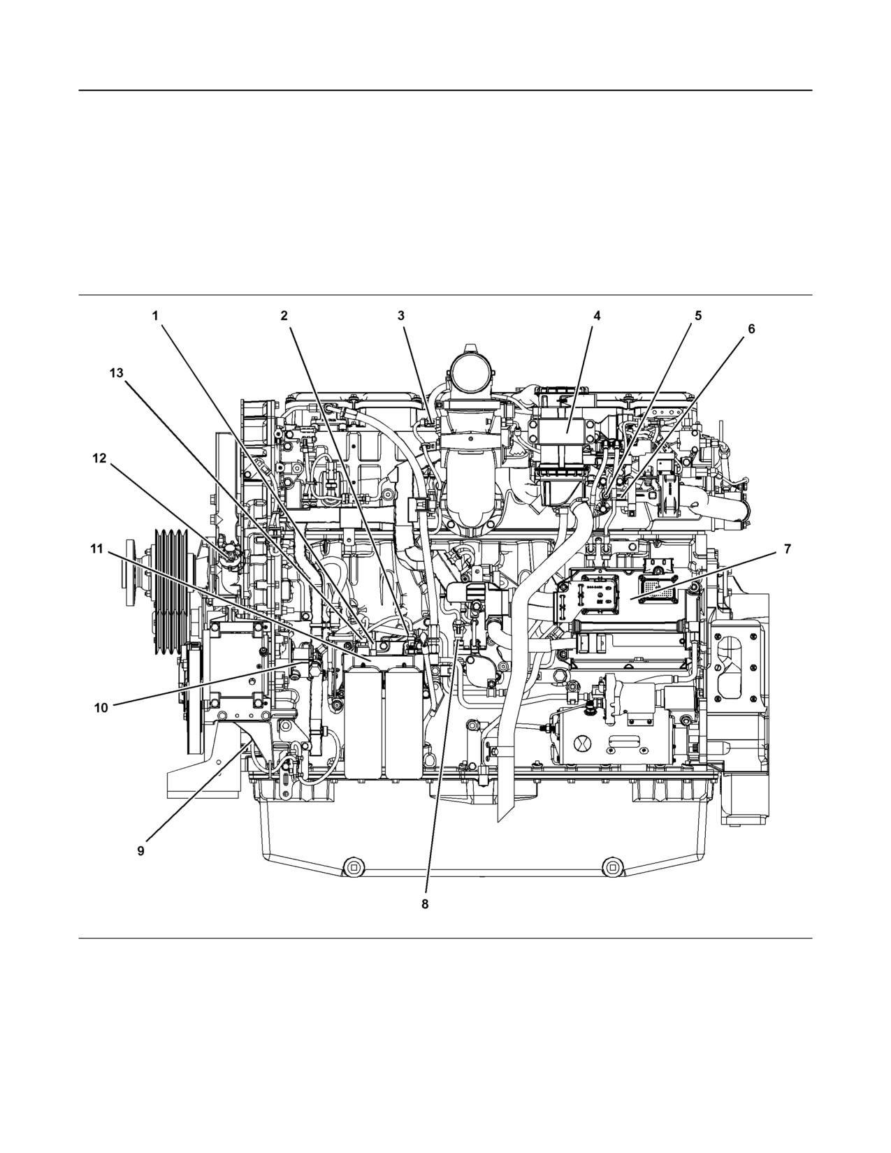
Illustration 12
g02272773
Left side view of a typical C15 or C18 Industrial Engine
(1) Fuel pressure sensor pre-filter
(6) NRS valve
(11) Secondary fuel filter base
(2) Fuel pressure sensor post-filter
(7) Engine control module (ECM)
(12) Oil filler
(3) Charge air cooler outlet sensor
(8) Crankcase pressure sensor
(13) Fuel temperature sensor
(4) Open crankcase ventilation breather
(9) Engine speed sensor
(5) NRS temperature sensor
(10) Fuel pump
SEBU8598
17
General Information
Product Description
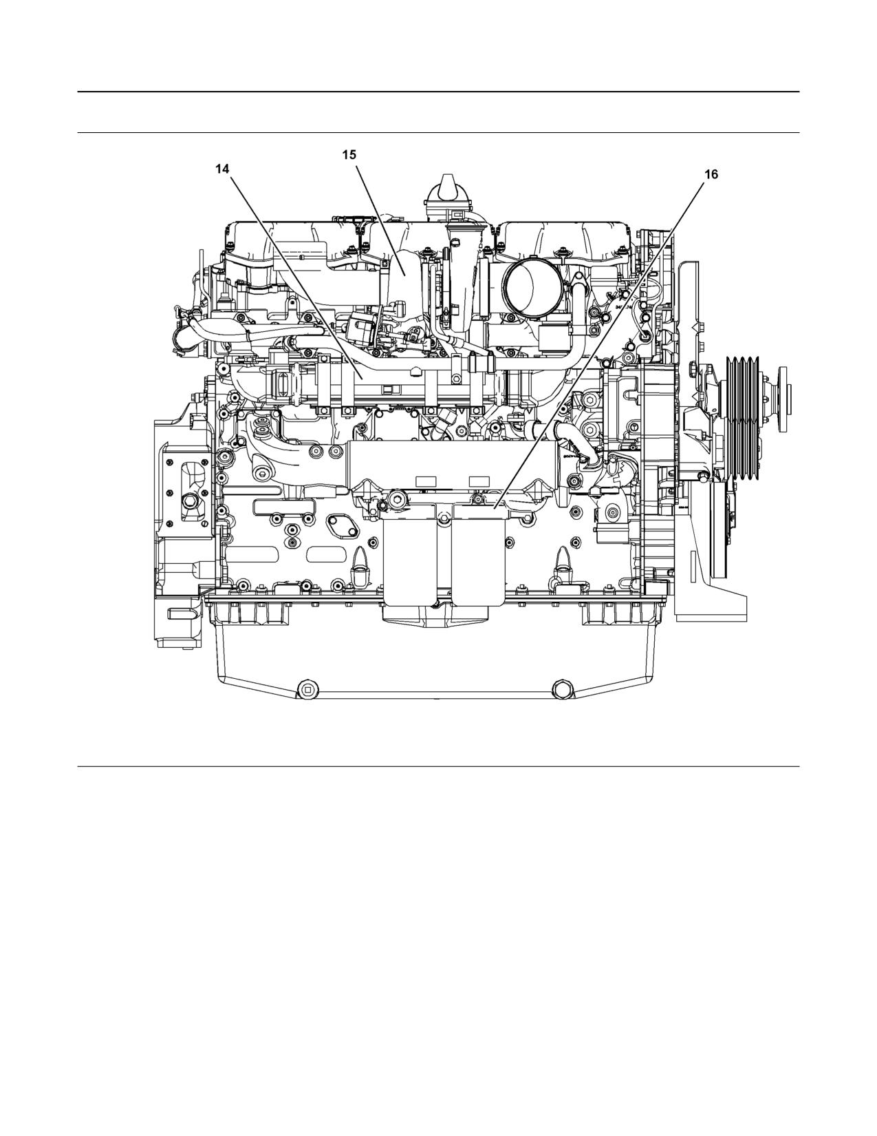
Illustration 13
g02272613
Right side view of a typical C15 or C18 Industrial Engine
(14) NRS cooler
(15) Turbocharger
(16) Oil filter base
i04061067
• Four stroke cycle
• Mechanically actuated electronically controlled fuel
Product Description
injection system
SMCS Code: 1000; 4450; 4491
• Turbocharged
Engine Description
Engine Specifications
The Caterpillar C15 and C18 Industrial Engine
provides the following features:
Note: The front end of the engine is opposite the
flywheel end of the engine. The left and the right
sides of the engine are determined from the flywheel
end. The number 1 cylinder is the front cylinder.
18
SEBU8598
General Information
Product Description
Electronic Engine Features
The Caterpillar C15 and C18 Engine are designed
for electronic controls. The integral on board
computer controls the operation of the engine.
Current operating conditions are monitored. The
Electronic Control Module (ECM) controls the
response of the engine to these conditions and to the
demands of the operator. These conditions and
operator demands determine the precise control of
fuel injection by the ECM. The electronic engine
control system provides the following features:
• Engine speed governor
• Automatic air/fuel ratio control
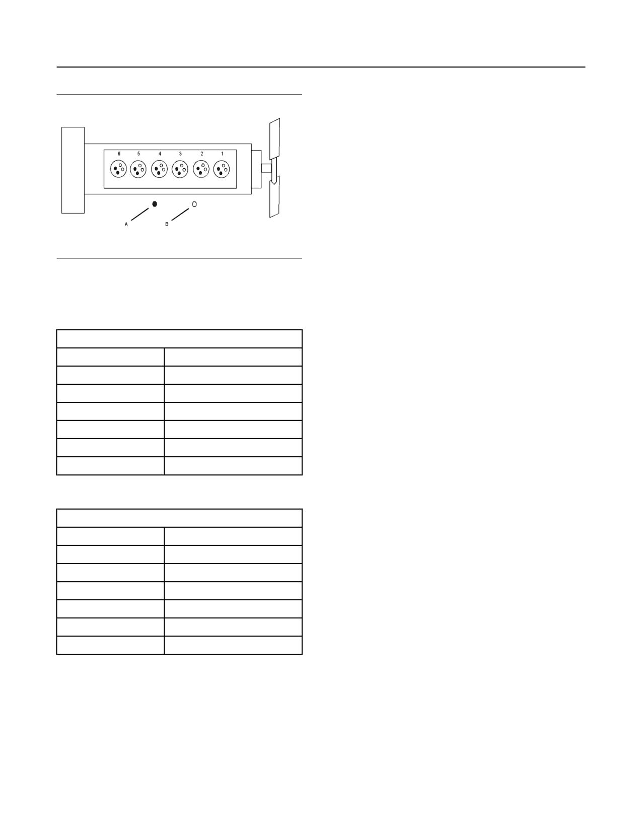
Illustration 14
g01387009
• Torque rise shaping
Cylinder and valve location
(A) Exhaust valve
• Injection timing control
(B) Inlet valve
• System diagnostics
Table 1
C15 Engine Specifications
• Aftertreatment regeneration control
Arrangement and Cylinders
In-line six cylinder
• NOx reduction system control
Bore
137 mm (5.4 inch)
Additional Features
Stroke
171 mm (6.7 inch)
The following additional features provide increased
Aspiration
ATAAC(1)
engine fuel economy and serviceability:
Displacement
15.2 L (928 cubic inch)
• Cold starting capability
Firing Order
1-5-3-6-2-4
• Tampering detection
Rotation (flywheel end)
Counterclockwise
(1) Air-to-air aftercooled
• Diagnostics
Table 2
Engine Diagnostics
C18 Engine Specifications
The engine has built-in diagnostics in order to ensure
Arrangement and Cylinders
In-Line six cylinder
that all of the components are functioning properly.
Under certain conditions, the engine horsepower and
Bore
145 mm (5.7 inch)
the vehicle speed may be limited. A Caterpillar
Stroke
183 mm (7.2 inch)
electronic service tool may be used to display the
diagnostic code.
Aspiration
ATAAC(1)
There are two categories of codes: diagnostic code
Displacement
18.1 L (1105 cubic inch)
and event code. These two categories of codes may
Firing Order
1-5-3-6-2-4
be in two different states: active and logged.
Rotation (flywheel end)
Counterclockwise
Most of the diagnostic codes are logged and stored in
the ECM. For additional information, refer to the
(1) Air-to-air aftercooled
Operation and Maintenance Manual, “Engine
Diagnostics” topic (Operation Section).
Engine Service Life
Engine efficiency and maximum utilization of engine
performance depend on the adherence to proper
operation and maintenance recommendations. In
addition, use recommended fuels, coolants, and
lubricants. Use the Operation and Maintenance
Manual as a guide for required engine maintenance.
SEBU8598
19
General Information
Product Description
Expected engine life is predicted by the average
power that is demanded. The average power that is
demanded is based on fuel consumption of the
engine over a time. Reduced hours of operation at full
throttle and/or operating at reduced throttle settings
result in a lower average power demand. Reduced
hours of operation will increase the length of
operating time before an engine overhaul is required.
For more information, refer to the Operation and
Maintenance Manual, “Overhaul Considerations”
topic (Maintenance Section).
Aftermarket Products and Caterpillar
Engines
NOTICE
In order to maximize fuel system life and prevent pre-
mature wear out from abrasive particles in the fuel, a
four micron[c] absolute high efficiency fuel filter is re-
quired for all Caterpillar common rail fuel systems.
Caterpillar High Efficiency Fuel Filters meet these re-
quirements. Consult your Caterpillar dealer for the
proper part numbers.
When auxiliary devices, accessories, or consumables
(filters, additives, catalysts, etc.) which are made by
other manufacturers are used on Caterpillar
products, the Caterpillar warranty is not affected
simply because of such use.
However, failures that result from the installation
or use of devices, accessories, or consumables
from other manufacturers are NOT Caterpillar
defects. Therefore, the defects are NOT covered
under the Caterpillar warranty.
20
SEBU8598
Product Identification Information
Plate Locations and Film Locations
Product Identification
Information
i04092302
Plate Locations and Film
Locations
SMCS Code: 1000; 4450
Illustration 17
g02272993
View of the top of a typical C15 or C18 Industrial
Engine
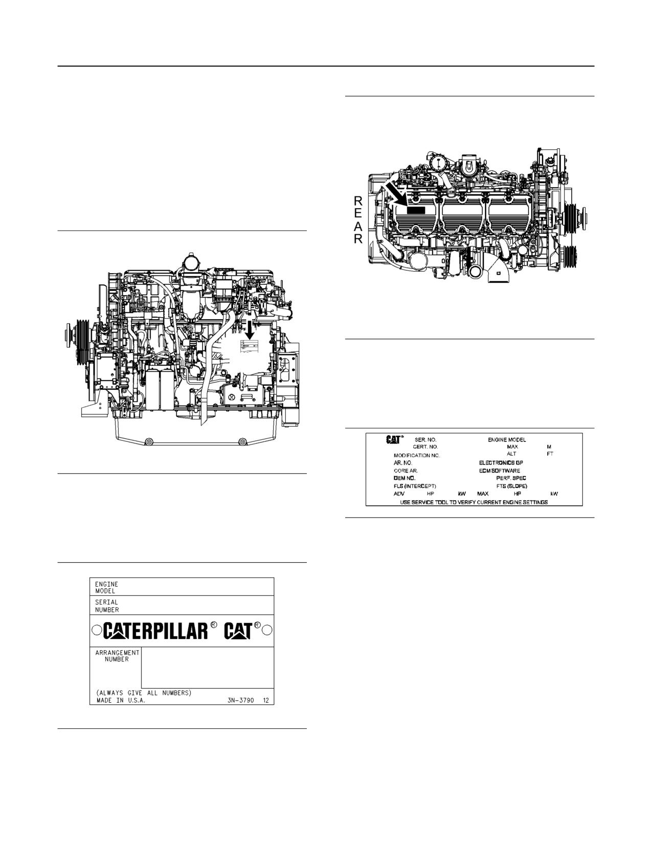
The engine information plate is located toward the
rear of the valve cover. The engine information plate
may be read from the right side of the engine.
Illustration 15
g02273593
View of the left side of a typical C15 or C18 Industrial
Engine
Illustration 18
g01347963
The serial number plate is located on the left side of
the cylinder block. The engine control module will
Engine information plate
obstruct the view of the serial number plate.
The following information is on the information plate:
engine serial number, engine model, engine
arrangement number, maximum altitude of the engine
that is necessary to achieve the rated power,
horsepower, high idle, full load rpm, fuel settings and
other information
Illustration 16
g00123229
Serial number plate
The following information is stamped on the serial
number plate: engine serial number, engine model
and arrangement number.
SEBU8598
21
Product Identification Information
Emissions Certification Film
This label is located on the engine.
i00844066
Emissions Certification Film
SMCS Code: 1000; 7405
S/N: BDN1-Up
Illustration 21
g00284658
EPA Emissions Certification Film
Illustration 19
g02236893
View of the exhaust system of a C15 or C18 Industrial
Engine
Illustration 22
g00415538
European Emissions Certification Film
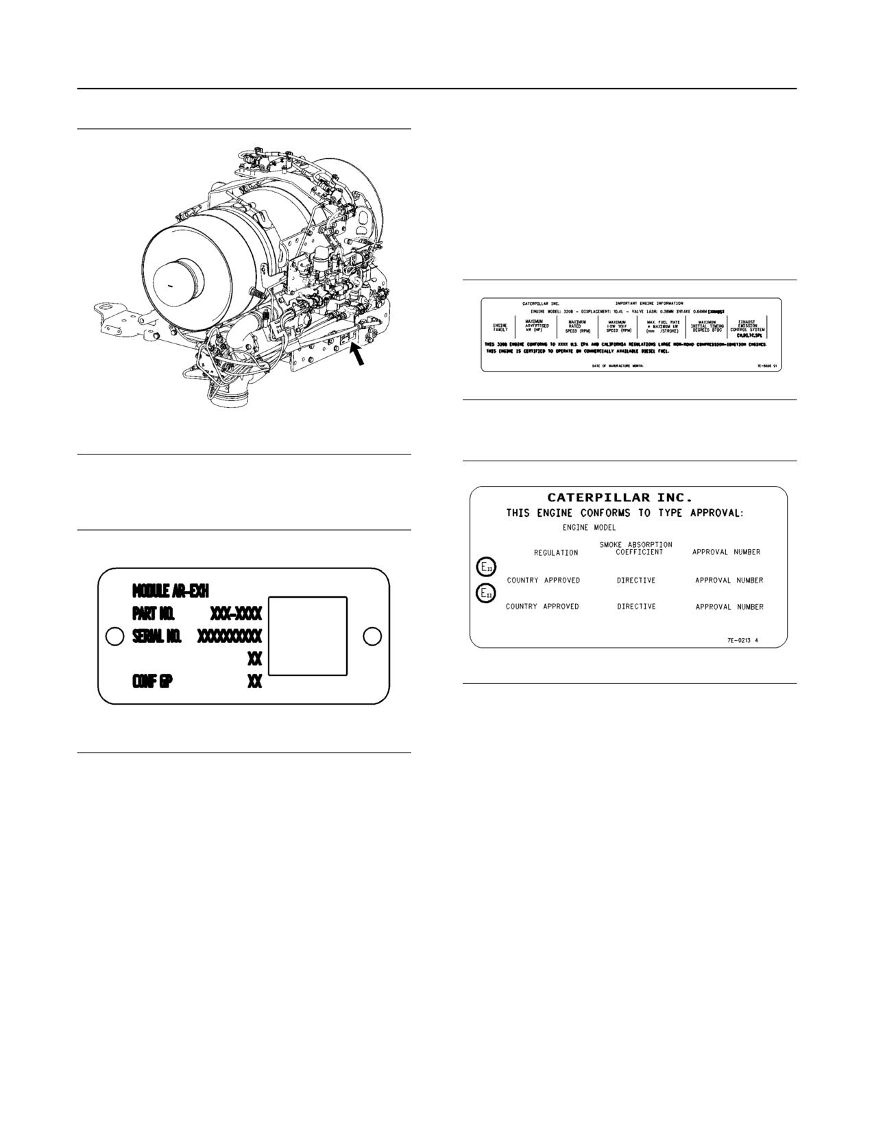
The EPA Emissions Certification Film (if equipped)
and/or the European Emissions Certification Film (if
Illustration 20
g02236574
equipped) is located on the side of the engine.
CEM plate
The Clean Emission Module (CEM) identification
i01382270
plate contains the following information: part number,
serial number, change level and configuration ID
Reference Information
code. This information may be needed by the Cat
SMCS Code: 1000; 4450
dealer when inquiries are being made on the CEM.
Identification of the items in Table 3 may be needed
i04019095
in order to obtain parts and service. Some of the
information is on the engine Serial Number Plate and/
or Information Plate. Locate the information for your
Emissions Certification Film
engine. Record the information on the appropriate
SMCS Code: 1000; 7405
space in Table 3 . Make a copy of this list for a record.
Retain the information for future reference.
Note: This information is pertinent in the United
States, in Canada and in Europe.
Consult your Cat dealer for an Emission Control
Warranty Statement.
22
SEBU8598
Product Identification Information
Reference Information
The top level part numbers in the Parts Manual for the
engine are listed with the engine arrangement
number. Occasionally, an arrangement may be
slightly modified before the product is shipped from
the factory. In these cases, a modification number
indicates that the arrangement has been modified.
The packaging arrangement may also be called a
pricing arrangement or a customer arrangement. This
is the total package with attachments and options that
are not included in the engine arrangement.
The performance specification can be used by your
Caterpillar dealer with the Technical Marketing
Information system. Before the engine leaves the
factory, the engine performance is tested. Detailed
performance data is recorded. The performance
specification number can be used for obtaining the
data.
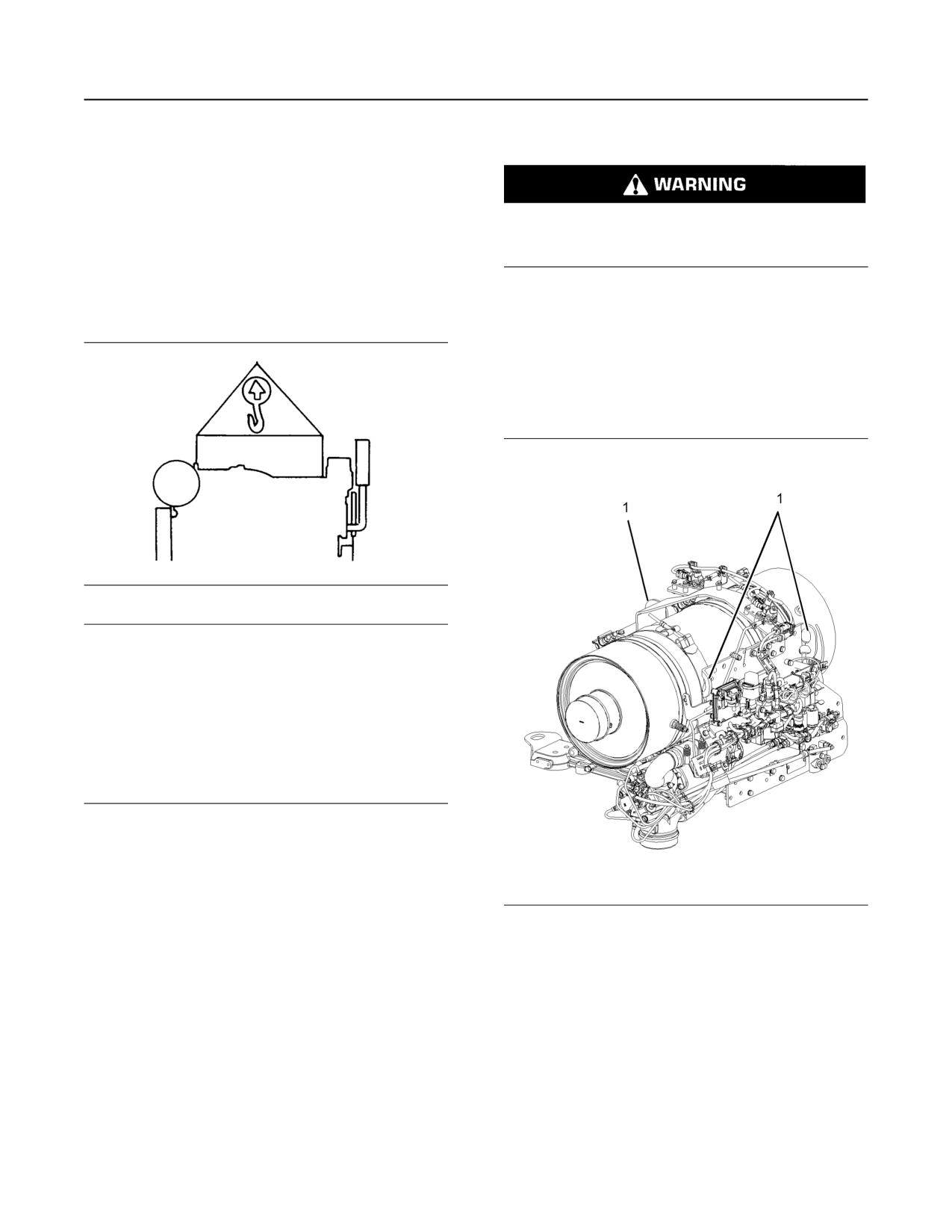
Table 3
Reference Information
Engine Model
Serial Number
Arrangement Number
Modification Number
Packaging Arrangement
Turbocharger
Fuel Filter Element
Lubrication Oil Filter Element
Auxiliary Oil Filter Element
Air Cleaner Element
Fan Drive Belt
Alternator Belt
Capacity of the Lubrication
System
Capacity of the Cooling System
Performance Specification
Number
Personality Module
Low Idle rpm
High Idle rpm
Full Load rpm
Power Rating
SEBU8598
23
Operation Section
Product Lifting
Engine Lifting with a Fuel Tank
Operation Section
Lifting and Storage
Lift eyes or tank can fail when lifting tank contain-
ing fluids resulting in possible personal injury.
i04037083
Drain tank of all fluids before lifting.
Product Lifting
Lifting the engine with a fuel tank that is mounted to
SMCS Code: 7000; 7002
the engine requires special equipment and
procedures. Do not lift the unit with fuel in the fuel
tank. Consult your Caterpillar dealer for information
regarding fixtures for proper lifting of your complete
package.
Clean Emission Module Lifting
Illustration 23
g00103219
NOTICE
Never bend the eyebolts and the brackets. Only load
the eyebolts and the brackets under tension. Remem-
ber that the capacity of an eyebolt is less as the angle
between the supporting members and the object be-
comes less than 90 degrees.
When it is necessary to remove a component at an
angle, only use a link bracket that is properly rated for
the weight.
Use a hoist to remove heavy components. Use an
adjustable lifting beam to lift the engine. All
supporting members (chains and cables) should be
parallel to each other. The chains and cables should
be perpendicular to the top of the object that is being
lifted.
Illustration 24
g02240095
Some removals require lifting the fixtures in order to
The Clean Emission Module (CEM) should only be
obtain proper balance and safety.
lifted by the designated lifting eyes (1). Lifting eye
locations will be different depending on the CEM
To remove the engine ONLY, use the lifting eyes that
arrangement. Do not attempt to lift the CEM using
are on the engine.
straps around the diesel particulate filter.
Lifting eyes are designed and installed for the specific
engine arrangement. Alterations to the lifting eyes
and/or the engine make the lifting eyes and the lifting
fixtures obsolete. If alterations are made, ensure that
proper lifting devices are provided. Consult your
Caterpillar dealer for information regarding fixtures
for proper engine lifting.
24
SEBU8598
Lifting and Storage
Product Storage
i05242858
Note: The mixture of VCI oil can be added to the inlet
by removing the plug for checking turbocharger boost
Product Storage
pressure. The minimum application rate for the VCI
oil mixture is 5.5 mL per L (3 oz per 1000 cu in) of
SMCS Code: 7002
engine displacement.
Storage (Less Than One Year)
8. Use a sprayer to apply a mixture of 50 percent VCI
oil and 50 percent crankcase oil into the exhaust
If an engine is not used, oil can run off the following
openings. The minimum application rate for the oil
parts that normally receive lubrication: cylinder walls,
mixture is 5.5 mL per L (3 oz per 1000 cu in) of
piston rings, main bearings, connecting rod bearings,
engine displacement. Seal the exhaust pipe and
crankshaft and gears.
seal any drain holes in the muffler.
This lack of lubricant allows corrosion to begin to
appear on the metal. This condition is worse in areas
9. Remove the fuel from the secondary fuel filter
of high humidity.
housing. Alternately, empty and reinstall the spin-
on fuel filter element in order to remove any dirt
When the engine is started again, metal to metal
and water. Drain any sleeve metering fuel pump.
contact will cause wear before the surfaces receive
oil. To minimize this wear, use the starter to turn the
engine with the throttle in the FUEL OFF position.
Clean the primary fuel filter. Fill with calibration
When oil pressure is shown on the pressure gauge,
fluid or kerosene. Install the primary fuel filter and
start the engine.
operate the priming pump. This procedure will
send clean oil to the secondary filter and the
engine.
1. Clean the engine of any dirt, rust, grease, and oil.
Inspect the exterior. Paint areas that contain paint
Open the fuel tank drain valve in order to drain any
damage with a good quality paint.
water and dirt from the fuel tank. Apply a spray of
calibration fluid or kerosene at the rate of
2. Remove dirt from the air cleaners. Check all seals,
30 mL per 30 L (1 oz per 7.50 gal US) of fuel tank
gaskets, and the filter element for damage.
capacity in order to prevent rust in the fuel tank.
Add 0.15 mL per L (.02 oz per 1 gal US) of
3. Apply lubricant to all points in this Operation and
commercial biocide such as Biobor JF to the fuel.
Maintenance Manual, “Maintenance Interval
Apply a small amount of oil to the threads on the
Schedule”.
fuel tank filler neck and install the cap. Seal all
openings to the tank in order to prevent
4. Drain the crankcase oil. Replace the crankcase oil
evaporation of the fuel and as a preservative.
and change the oil filters. For the proper
procedure, refer to this Operation and
10. Remove the fuel nozzles or spark plugs. Apply
Maintenance Manual.
30 mL (1 oz) of the mixture of oils (50 percent VCI
oil and 50 percent engine oil) into each cylinder.
5. If the engine is equipped with an air starting motor,
fill the reservoir with the following mixture: 50
Use a bar or a turning tool in order to turn over the
percent volatile corrosion inhibitor oil
engine slowly. This procedure puts the oil on the
cylinder walls. Install all fuel nozzles or spark plugs
(<nomen>VCI oil</nomen>) and 50 percent
and tighten to the correct torque.
engine oil.
11. Spray a thin amount of a mixture of 50 percent
6. Add VCI oil to the crankcase oil. The volume of VCI
VCI oil and 50 percent engine oil onto the following
oil in the crankcase oil should be 3 to 4 percent.
components: flywheel, ring gear teeth and starter
Note: If the engine crankcase is full, drain enough
pinion. Install the covers in order to prevent
engine oil so the mixture can be added.
evaporation of the vapors from the VCI oil.
7. Remove the air filter elements. Turn the engine at
12. Apply a heavy amount of Cat Multipurpose
cranking speed with the throttle control in FUEL
Grease (MPGM) to all outside parts that move,
OFF position. Use a sprayer to add a mixture of 50
such as rod threads, ball joints, linkage.
percent VCI oil and 50 percent engine oil into the
Note: Install all covers. Ensure that tape has been
air inlet or turbocharger inlet.
installed over all openings, air inlets, exhaust
openings, the flywheel housing, the crankcase
breathers, the dipstick tubes.
SEBU8598
25
Lifting and Storage
Product Storage
Ensure that all covers are airtight and
6. Use a bar or a turning tool in order to turn the
weatherproof. Use a waterproof weather resistant
engine in the normal direction of rotation. The
tape such as Kendall No. 231 or an equivalent.
procedure ensures that no hydraulic locks or
Do not use duct tape. Duct tape will only seal for a
resistance exist.
short time.
7. Before starting the engine, remove the valve cover
13. Under most conditions, removing the batteries is
or covers. Put a large amount of engine oil on the
the best procedure. As an alternative, place the
camshaft, cam followers, and valve mechanism in
batteries in storage. As needed, periodically
order to prevent damage to the mechanism.
charge the batteries while the batteries are in
storage.
8. Pressure-lubricate the engine before starting the
engine. Pressure lubricating the engine ensures
If the batteries are not removed, wash the tops of
the batteries until the tops are clean. Apply an
immediate lubrication and prevents damage to the
electrical charge to the batteries in order to obtain
engine during the first few minutes of engine
a specific gravity of 1.225.
operation. If the engine is not equipped with a
prelube pump, contact your Cat dealer for
Disconnect the battery terminals. Place a plastic
information about lubrication of the engine before
cover over the batteries.
starting the engine.
Note: For additional information, refer to Special
Instruction, SEHS7633, “Battery Test Procedure”.
9. Check the condition of all rubber hoses. Replace
any worn hoses. Replace any damaged hoses.
14. Loosen all belts.
10. Before start-up, test the cooling system for a 3
15. Place a waterproof cover over the engine. Ensure
percent ro a 6 percent concentration of coolant
that the engine cover is secure. The cover should
conditioner. Add liquid coolant conditioner or a
be loose enough to allow air to circulate around the
coolant conditioner element, if equipped.
engine in order to prevent damage from
condensation.
Test the coolant mixture for proper nitrite level. If
necessary, adjust the coolant mixture.
16. Attach a tag with the storage date to the engine.
Prime the engine with clean diesel fuel before
17. Remove the waterproof cover at 2 month or 3
starting.
month intervals in order to check the engine for
11. Ensure that the cooling system is clean. Ensure
corrosion. If the engine has signs of corrosion,
that the system is full. Ensure that the system has
repeat the protection procedure.
the correct amount of supplemental cooling system
conditioner.
Coolant System
12. On the first day of operation, check the entire
Completely fill the cooling system before storage.
engine several times for leaks and correct
operation.
Refer to this Operation and Maintenance Manual,
“Fluid Recommendations” for more information about
coolants.
13. If the engine was removed from storage in which
temperatures of less than -12°C (10°F) were
Removal from Storage
encountered, refer to Service Manual, SEBU5898,
“Cold Weather Recommendations Operation and
1. Remove all outside protective covers.
Maintenance”.
2. Change the oil and filters.
Engines with 2 year preservation group
3. Check the condition of the fan and alternator belts.
from the factory
Replace the belts, if necessary. Refer to this
Operation and Maintenance Manual, “Belts -
Note: Engines that are stored more than 6 months
Inspect/Adjust/Replace” for the correct procedure.
must be prelubed and rotated in 6 month intervals.
For engines purchased with a factory applied, 2 year
4. Replace the fuel filter elements.
preservation group, follow the instructions from this
Operation and Maintenance Manual, “Removal From
5. Remove the plastic covers from the air cleaner
Storage”, step 8 and in this Operation and
elements.
Maintenance Manual, “Storage (less than 1 year)”
section.
26
SEBU8598
Lifting and Storage
Product Storage
For engine CEM's stored for more than one year, use
fuel system cleaner (part no. 343-6210) or equivalent
as recommenced in PEHJ0237, for 80 hours of
operation.
SEBU8598
27
Features and Controls
Battery Disconnect Switch
i05316709
Features and Controls
Monitoring System
i03646563
SMCS Code: 1900; 7400; 7450; 7451
Battery Disconnect Switch
The monitoring system is designed to alert the
(If Equipped)
operator to an immediate problem with any of the
engine systems that are monitored. The Monitoring
SMCS Code: 1411
System is also designed to alert the operator to an
impending problem with any of the engine systems
The battery disconnect switch and the engine start
that are monitored.
switch perform different functions. Turn off the battery
disconnect switch in order to disable the entire
The monitoring system parameters can be accessed
electrical system. The battery remains connected to
via the Cat ET service tool. Many of the parameters
the electrical system when you turn off the engine
within the monitoring system can be tailored to suit
start switch.
the operation of the engine.
Turn the battery disconnect switch to the OFF
An example of adjustments that may be made within
position and remove the key when you service the
the monitoring system is changing the setpoint of the
electrical system or any other components.
engine overspeed indicator from the factory default
setting.
Also turn the battery disconnect switch to the OFF
position and remove the key when the engine will not
be used for an extended period of a month or more.
Indicators and Gauges
This will prevent drainage of the battery.
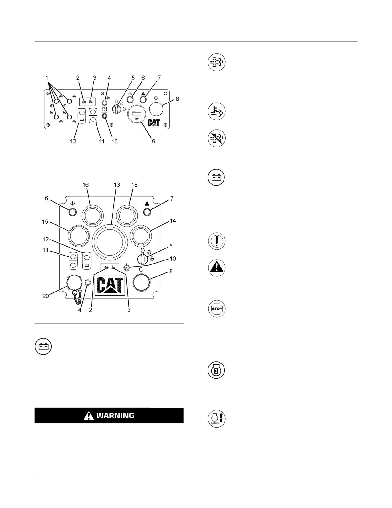
The instrument panel may look like the instrument
panel that is pictured in illustration 25 or the
NOTICE
instrument panel may look like the instrument panel
Never move the battery disconnect switch to the OFF
that is pictured in illustration 26 . The instrument
position while the engine is operating. Serious dam-
panel may not include all of the instruments that are
age to the electrical system could result.
shown in the illustration.
To ensure that no damage to the engine occurs, verify
that the engine is fully operational before cranking the
engine. Do not crank an engine that is not fully
operational.
Perform the following procedure in order to check the
battery disconnect switch for proper operation:
1. With the battery disconnect switch in the ON
position, verify that electrical components are
functioning. Verify that the hour meter is displaying
information. Verify that the engine will crank.
2. Turn the battery disconnect switch to the OFF
position.
3. Verify that the following items are not functioning:
electrical components, hour meter and engine
cranking. If any of the items continue to function
with the battery disconnect switch in the OFF
position, consult your Caterpillar dealer.
28
SEBU8598
Features and Controls
Monitoring System
Diesel Particulate Filter (DPF) Lamp (2) -
The DPF lamp will illuminate when a
regeneration of the DPF is needed. Refer
to this Operation and Maintenance Manual,
“Diesel Particulate Filter Regeneration” for more
information on this lamp.
High Exhaust Temperature Lamp (3) -
This lamp is illuminated when a DPF
regeneration is active.
Regeneration Disabled (4) - This lamp
will be illuminated if the regeneration is
manually disabled through the
regeneration switch or through the Cat (ET)
service tool.
Illustration 25
g02212133
Start Switch (5) - The start switch has
three positions: OFF, RUN and START.
When the start switch is turned
clockwise to the RUN position, the lamps will
flash for 5 seconds during the system test. The
lamps will then shut off. In the RUN position, the
Electronic Control Module (ECM) and electronic
systems are powered up.
Diagnostic Lamp (6) - The diagnostic
lamp will illuminate when an active fault
code is present.
Shutdown Lamp (7) - The shutdown
lamp will illuminate when a critical
engine event occurs which requires that
the engine be shut down. The event should be
addressed as quickly as possible.
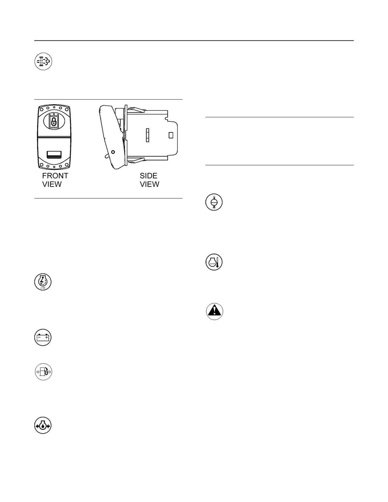
Shutdown Switch (8) - Use the engine
shutdown switch in order to stop the
engine. Push the shutdown switch in
order to put the switch in the OFF position.
Illustration 26
g02215293
Moving the switch to the OFF position will stop
the engine. After the engine stops, turn the knob
Circuit Breaker (1) - Reset the circuit
clockwise. Turning the knob will reset the engine
breaker if a circuit breaker trips. Press
shutdown switch to the ON position.
the button in order to reset the circuit
breaker. If the electrical system is working
Service Hour Meter (9) - This gauge
properly, the button will remain pressed. If the
indicates the total number of clock hours
button does not remain pressed or if the circuit
of engine operation. Hours of operation
breaker trips soon after being reset, check the
are logged in the ECM. A service tool is needed to
appropriate electrical circuit. Repair the electrical
retrieve the hours from the ECM. A Service Hour
circuit, if necessary.
Meter may be installed on the engine.
Idle Speed Switch (10) - When the switch
is in the up position, the engine speed
increases to HIGH IDLE. When the
Resetting the circuit breakers in a flammable at-
switch is in the down position, the engine speed
mosphere or a combustible atmosphere may lead
decreases to LOW IDLE.
to fire hazards or explosion hazards which may
result in personal injury or death. DO NOT reset
the circuit breaker when a flammable atmosphere
or a combustible atmosphere is present and the
power has not been removed from the equipment.
SEBU8598
29
Features and Controls
Monitoring System
Regeneration Switch (11) - Used to
A lower oil pressure is normal at low idle. If the load is
activate a forced regeneration or
stable and the gauge reading changes, perform the
manually disable regeneration. Refer to
following procedure:
this Operation and Maintenance Manual, “Diesel
1. Remove the load.
Particulate Filter Regeneration” for more
information on this switch.
2. Reduce engine speed to low idle.
3. Check and maintain the oil level.
NOTICE
To help prevent engine damage, never exceed the
high idle rpm. An overspeed can result in serious
damage to the engine. The engine can be operated at
high idle without damage, but the engine should
never be allowed to exceed the high idle rpm.
Note: The high idle rpm and the full load rpm are
stamped on the Information Plate.
Jacket Water Coolant Temperature (17) -
Illustration 27
g02333673
Typical temperature range is 87 to 98°C
(189 to 208°F). Higher temperatures may
OK to Elevate Idle Switch (12) - Pressing in and
occur under certain conditions. The water
locking the “OK to Elevate Idle” switch enables the
temperature reading may vary according to load.
engine ECM to elevate engine speed automatically
The reading should never exceed the boiling
when needed. For example, if the engine is running at
point for the pressurized system that is being
low idle and a DPF regeneration is activated, having
used.
the “OK to Elevate Idle” switch in the LOCKED
position will allow the engine speed to increase in
Coolant Temperature (18) - When the
order for the DPF regeneration to occur.
coolant temperature is above the normal
operating value, the coolant temperature
Tachometer (13) - This gauge indicates
gauge will be in the red zone. Refer to the
engine speed (rpm). When the throttle
Messenger panel for any additional information
control lever is moved to the full throttle
that may be available.
position without load, the engine is running at
high idle. The engine is running at the full load
Warning Lamp (19) - There is a general
rpm when the throttle control lever is at the full
fault in the engine. Refer to the
throttle position with maximum rated load.
Messenger display for any additional
information that may be available.
Voltmeter (14) - This gauge indicates the
voltage of the electrical system. The
Service Tool Connector (20) - For more information
needle in the red range indicates low
about the use of Cat ET and the PC requirements for
voltage or high voltage.
Cat ET, refer to the documentation that
accompanies your Cat ET software.
Fuel Pressure (15) - This gauge
indicates fuel pressure to the fuel
Mini Industrial Power Display
injection pump from the fuel filter. A
decrease in fuel pressure usually indicates a dirty
(MIPD)
fuel filter or a plugged fuel filter. As the fuel filter
becomes plugged, there will be a noticeable
The mini industrial power display provides for a
reduction in the performance of the engine.
means to view various types of engine information.
The information that can be viewed is described
below.
Engine Oil Pressure (16) - The oil
pressure should be greatest after a cold
engine is started. The pressure will
decrease as the engine warms up. The pressure
will increase when the engine rpm is increased.
The pressure will stabilize when the engine rpm is
stable.
30
SEBU8598
Features and Controls
Monitoring System
Engine Load - Displays the amount of load on the
engine as a percentage.
Regen Disable Status - Displays whether the
regeneration is manually disabled.
DPF Lamp - Displays when a DPF regeneration is
needed.
Soot Loading - Displays the amount of soot within
the DPF as a percentage.
Air Inlet Temperature - Displays the temperature of
the air entering the engine through the air filter.
Intake Manifold Air Temperature - Displays the
temperature of the air entering the engine at the
Illustration 28
g02216234
intake manifold.
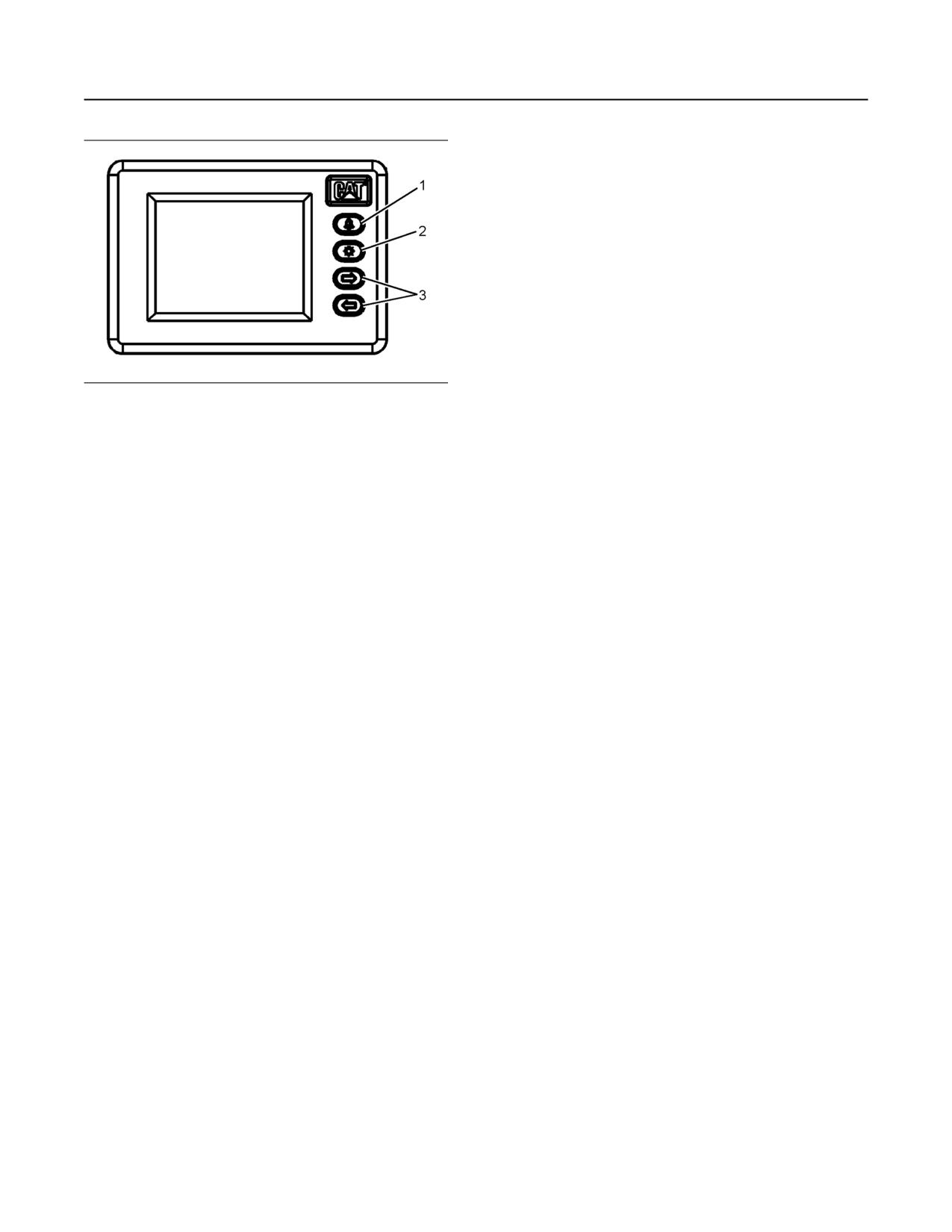
“OK/Select” button (1) - The “OK/Select” button is
Boost Pressure - Displays the amount of pressure
used to confirm the selections that were made with
of the air entering the intake manifold of the engine.
the “scroll left/right” buttons.
Crankcase Pressure - Displays the amount of
“Backlight” button (2) - This button is used to turn
pressure within the crankcase of the engine.
the backlight of the display on or off.
Atmospheric Pressure - Displays the amount of
“Scroll left/right button” (3) - This button is used to
atmospheric pressure that the engine is operating in.
advance through the various screens of the MIPD.
Fuel Temp - Displays the temperature of the fuel
entering the engine.
The MIPD comes with three preset user interfaces.
The interfaces are labeled as “Operator_1” ,
Fuel Rate - Displays the amount of fuel being used
“Operator_2” , and “Operator_3” .
by the engine.
“Operator_1” user interface is preset with various
Filtered Fuel Delta Pressure - Displays the
engine, aftertreatment, and transmission information
pressure across the fuel filter.
over 14 screens. Diagnostic and system information
is also included. The information in “Operator_1” is
Low Idle RPM - Displays the low idle speed setpoint
displayed via ISO symbols and metric display units.
in RPM.
“Operator_2” user interface is preset with various
Hi Idle Speed - Displays the high idle speed setpoint
engine, aftertreatment, and transmission information
in RPM.
over 12 screens. Diagnostic and system information
Desired Speed - Displays the desired engine speed
is also included. The information is displayed in
analog style gauges and English display units.
in RPM.
Primary Throttle - Displays the primary throttle
“Operator_3” user interface is preset with various
position as a percentage.
engine, aftertreatment, and transmission information
over 12 screens. Diagnostic and system information
Secondary Throttle - Displays the secondary
is also included. The information is displayed in
throttle position as a percentage.
analog style gauges and English display units.
Auxiliary Pressure Sensor 1 - Displays the
Note: Only use “Operator_1” and “Operator_2”
pressure being measured by the #1 auxiliary sensor if
interfaces on Tier 4 engines. The added
one is being used.
aftertreatment parameters in these interfaces are
Auxiliary Temperature Sensor 1 - Displays the
necessary to ensure proper operation.
temperature being measured by the #1 auxiliary
sensor if one is being used.
Parameters
Battery Voltage - Displays the battery voltage.
Below are a list of all the parameters that are
viewable through the three user interfaces used
Aftertreatment 1 Regeneration Status - Displays
within the MIPD.
the status of the regeneration system as manual or
automatic.
Engine Speed - Displays the current engine speed
in RPM.
HEST Lamp - Illuminates when a DPF regeneration
is active.
Coolant Temperature - Displays the current coolant
temperature of the engine.
SEBU8598
31
Features and Controls
Monitoring System
DPF Intake Temperature - Displays the temperature
of the exhaust gas entering the DPF.
DPF Outlet Temperature - Displays the temperature
of the exhaust gas leaving the DPF.
Transmission Selected Gear - Displays the
transmission gear being requested.
Transmission Requested Gear - Displays the
transmission gear being requested.
Transmission Oil Pressure - Displays the oil
pressure inside the transmission.
Transmission Oil Temperature - Displays the oil
temperature of the transmission.
Transmission Torque Limit - Displays the limit of
torque allowed by the transmission.
System Information
User Name - Displays the preset user name that is
selected.
Software Version - Displays the version of software
that is programmed in the MIPD.
Serial Number - Displays the serial number of the
MIPD.
Display Units - Displays the units of measurement
that is selected for the given user.
Engine Location - Displays which engine data is
being reported if more than one engine is connected
to the MIPD.
Language - Displays the selected language.
Alarm - Indicates whether audible alarm is set to ON
or OFF when an audible alarm is connected to the
MIPD.
32
SEBU8598
Engine Diagnostics
Self-Diagnostics
Engine Diagnostics
i00863835
Self-Diagnostics
SMCS Code: 1000; 1900; 1901; 1902
The electronic control module has some self-
diagnostic ability. When an electronic problem with an
input or an output is detected, a diagnostic code is
generated. This indicates the specific problem with
the circuitry.
Diagnostic codes are also generated when an
abnormal engine operating condition is detected. For
example, a diagnostic code will be generated if the
low oil pressure alarm is activated. In this case, the
diagnostic code indicates the symptom of a problem.
This type of diagnostic code is called an event. An
event is triggered by the detection of an abnormal
engine operating condition.
A diagnostic code which represents a problem that
currently exists is called an active code.
A diagnostic code that is stored in memory is called a
logged code. Always service active codes prior to
servicing logged codes. Logged codes may include
the following categories:
• Intermittent problems
• Recorded events
• Performance history
Logged codes may not indicate that a repair is
needed. The problems may have been repaired since
the logging of the code. Logged codes may be helpful
to troubleshoot intermittent problems.
SEBU8598
33
Engine Starting
Before Starting Engine
•
Do not start the engine or move any of the controls
Engine Starting
if there is a “DO NOT OPERATE” warning tag or
similar warning tag attached to the start switch or
i02109067
to the controls.
Before Starting Engine
•
Ensure that the areas around the rotating parts are
clear.
SMCS Code: 1000; 1400; 1450
•
All of the guards must be put in place. Check for
Perform the required daily maintenance and other
damaged guards or for missing guards. Repair any
periodic maintenance before the engine is started.
damaged guards. Replace damaged guards and/
Inspect the engine compartment. This inspection can
or missing guards.
help prevent major repairs at a later date. Refer to the
Operation and Maintenance Manual, “Maintenance
•
Disconnect any battery chargers that are not
Interval Schedule” for more information.
protected against the high current drain that is
• For the maximum service life of the engine, make
created when the electric starting motor (if
a thorough inspection before the engine is started.
equipped) is engaged. Check electrical cables and
Look for the following items: oil leaks, coolant
check the battery for poor connections and for
leaks, loose bolts and trash buildup. Remove trash
corrosion.
buildup and arrange for repairs, as needed.
•
Reset all of the shutoffs or alarm components.
• Inspect the aftercooler for loose connections and
•
Check the engine lubrication oil level. Maintain the
for debris buildup.
oil level between the “ADD” mark and the “FULL”
• Inspect the cooling system hoses for cracks and
mark on the oil level gauge.
for loose clamps.
•
Check the coolant level. Observe the coolant level
• Inspect the alternator and accessory drive belts for
in the coolant recovery tank (if equipped). Maintain
cracks, breaks, and other damage.
the coolant level to the “FULL” mark on the
coolant recovery tank.
• Inspect the wiring for loose connections and for
worn wires or frayed wires.
•
If the engine is not equipped with a coolant
recovery tank maintain the coolant level within
• Check the fuel supply. Drain water from the water
13 mm (0.5 inch) of the bottom of the filler pipe. If
separator (if equipped). Open the fuel supply
the engine is equipped with a sight glass, maintain
valve.
the coolant level in the sight glass.
NOTICE
•
Observe the air cleaner service indicator (if
equipped). Service the air cleaner when the yellow
All valves in the fuel return line must be open before
diaphragm enters the red zone, or when the red
and during engine operation to help prevent high fuel
piston locks in the visible position.
pressure. High fuel pressure may cause filter housing
failure or other damage.
•
Ensure that any driven equipment has been
disengaged. Minimize electrical loads or remove
If the engine has not been started for several weeks,
any electrical loads.
fuel may have drained from the fuel system. Air may
have entered the filter housing. Also, when fuel filters
i04132731
have been changed, some air pockets will be trapped
in the engine. In these instances, prime the fuel
Cold Weather Starting
system. Refer to the Operation and Maintenance
Manual, “Fuel System - Prime” for more information
SMCS Code: 1000; 1250; 1450; 1453; 1456; 1900
on priming the fuel system.
Startability will be improved at temperatures below
10°C (50°F) from the use of a cylinder block coolant
heater or from other means that are used to heat the
crankcase oil. Some engine applications use a jacket
Engine exhaust contains products of combustion
water heater to improve startability. Use of a jacket
which may be harmful to your health. Always start
water heater will help reduce white smoke and misfire
and operate the engine in a well ventilated area
during start-up in cold weather.
and, if in an enclosed area, vent the exhaust to the
outside.
34
SEBU8598
Engine Starting
Starting the Engine
Note: If the engine has not been run for several
During the key on, the diagnostic lamp, warning
weeks, fuel may have drained. Air may have moved
lamp, regeneration lamps, and DPF disabled lamp
into the filter housing. Also, when fuel filters have
will be checked for proper bulb operation. If any of
the lamps do not illuminate, replace the bulb.
been changed, some air will be left in the filter
housing. Refer to the Operation and Maintenance
Manual, “Fuel System - Prime” (Maintenance
NOTICE
Section) for more information on priming the fuel
Do not engage the starting motor when flywheel is
system.
turning. Do not start the engine under load.
Ether Injection System (If
If the engine fails to start within 30 seconds, release
Equipped)
the starter switch or button and wait two minutes to al-
low the starting motor to cool before attempting to
The ether injection system is controlled by the ECM.
start the engine again.
The ECM monitors the coolant temperature, intake air
temperature, ambient air temperature, and barometric
3. Push the start button or turn the ignition switch to
pressure to determine when ether injection is needed.
At sea level, ether will be used if any of the
the START position in order to crank the engine.
temperatures fails to exceed 0° C (32° F). This
temperature is subject to an increase as barometric
Do not push down or hold the throttle down while
the engine is cranked. The system will
pressure increases.
automatically provide the correct amount of fuel
that is needed to start the engine.
4. If the engine fails to start within 30 seconds,
Personal injury or property damage can result
release the start button, or the ignition switch. Wait
from alcohol or starting fluids.
for 2 minutes in order to allow the starting motor to
cool before attempting to start the engine again.
Alcohol or starting fluids are highly flammable
and toxic and if improperly stored could result in
injury or property damage.
NOTICE
Oil pressure should rise within 15 seconds after the
Follow the procedure in this Operation and
engine starts. Do not increase engine rpm until the oil
Maintenance Manual, “Starting the Engine”.
pressure gauge indicates normal. If oil pressure is not
indicated on the gauge within 15 seconds, DO NOT
operate the engine. STOP the engine, investigate
i04032033
and correct the cause.
Starting the Engine
5. Allow the engine to idle for approximately 3
SMCS Code: 1000; 1450
minutes. Idle the engine until the water
temperature gauge has begun to rise. Check all
gauges during the warm-up period.
Engine exhaust contains products of combustion
Note: Oil pressures and fuel pressures should be in
which may be harmful to your health. Always start
the normal range on the instrument panel. Engines
and operate the engine in a well ventilated area
that are equipped with “WARNING” lamps do not
and, if in an enclosed area, vent the exhaust to the
have an operating range. The “WARNING and
outside.
DIAGNOSTIC” lamp (if equipped) will flash while the
engine is cranking. The lamp should turn off after
proper engine oil pressure or fuel pressure is
Starting the Engine
achieved. Do not apply a load to the engine or
increase engine rpm until the oil pressure gauge
Refer to the Owner's Manual of the OEM for your type
indicates at least normal pressure. Inspect the engine
of controls. Use the following procedure to start the
for leaks and/or unusual noises.
engine.
1. Place the transmission in NEUTRAL. Disengage
the flywheel clutch in order to allow the engine to
start faster, and to reduce the draining of the
battery.
2. Turn the ignition switch to the ON position.
SEBU8598
35
Engine Starting
Starting with Jump Start Cables
If the engine is operated with a low load, the engine
2. If a wire is loose, push the wire back into the
will reach normal operating temperature sooner than
connector. Pull the wire again in order to ensure
idling the engine with no load. When the engine is
that the wire is secure.
idled in cold weather, increase the engine rpm to
approximately 1000 to 1200 rpm in order to warm up
3. Start the engine. If the engine does not start,
the engine more quickly. Do not exceed the
consult the nearest Caterpillar dealer for
recommended rpm in order to increase the speed of
assistance.
the warm-up. Limit unnecessary idle time to 10
minutes.
i02049673
Starting Problems
Starting with Jump Start
An occasional starting problem may be caused by
one of the following items:
Cables
(Do Not Use This Procedure in
• Low battery charge
Hazardous Locations that have
• Lack of fuel
Explosive Atmospheres)
• Problem with the wiring harness
SMCS Code: 1000; 1401; 1402; 1900
If the engine fuel system has been run dry, fill the fuel
tank and prime the fuel system. Refer to the
Operation and Maintenance Manual, “Fuel System -
Prime” topic (Maintenance Section).
The connection of battery cables to a battery and
If the other problems are suspected, perform the
the disconnection of battery cables from a battery
appropriate procedure in order to start the engine.
may cause an explosion which may result in in-
jury or death. The connection and the disconnec-
Problems with the Wiring Harness
tion of other electrical equipment may also cause
an explosion which may result in injury or death.
The procedures for the connection and the dis-
connection of battery cables and other electrical
equipment should only be performed in a nonex-
plosive atmosphere.
Improper jump start cable connections can cause
an explosion resulting in personal injury.
Prevent sparks near the batteries. Sparks could
cause vapors to explode. Do not allow jump start
cable ends to contact each other or the engine.
If the installation is not equipped with a backup
battery system, it may be necessary to start the
engine from an external electrical source.
First, determine the reason that it is necessary to start
with power from an external source. Refer to Special
Instruction, SEHS7768, “Use of the 6V-2150 Starting/
Illustration 29
g01248812
Charging Analyzer”.
ECM Connector J2/P2
Many batteries which are considered unusable are
Locate the ECM. Check the connector in order to
still rechargeable. After jump starting, the alternator
ensure that the connector is secure. Lightly pull each
may not be able to fully recharge batteries that are
of the wires in the chassis harness.
severely discharged. The batteries must be charged
to the proper voltage with a battery charger. For
1. Pull each wire with approximately 4.5 kg (10 lb) of
information on testing and charging, refer to the
force. The wire should remain in the connector.
Special Instruction, SEHS7633, “Battery Test
Procedure”.
36
SEBU8598
Engine Starting
After Starting Engine
• Check for fluid or air leaks at idle rpm and at one-
NOTICE
half full rpm (no load on the engine) before
Using a battery source with the same voltage as the
operating the engine under load. Operating the
electric starting motor. Use ONLY equal voltage for
engine at idle and at one-half full rpm with no load
jump starting. The use of higher voltage will damage
is not possible in some applications.
the electrical system.
• Operate the engine at low idle until all systems
Do not reverse the battery cables. The alternator can
achieve operating temperatures. Check all gauges
be damaged. Attach ground cable last and remove
during the warm-up period.
first.
When using an external electrical source to start the
Note: Gauge readings should be observed and the
engine, turn the generator set control switch to the
data should be recorded frequently while the engine
“OFF” position. Turn all electrical accessories OFF
is operating. Comparing the data over time will help to
before attaching the jump start cables.
determine normal readings for each gauge.
Comparing data over time will also help detect
Ensure that the main power switch is in the OFF posi-
abnormal operating developments. Significant
tion before attaching the jump start cables to the en-
changes in the readings should be investigated.
gine being started.
Extended Idle at Cold Ambient
1. Turn the start switch on the stalled engine to the
Temperature
OFF position. Turn off all accessories.
The engine may automatically change speeds when
2. Connect one positive end of the jump start cable to
the engine is idling in cold ambient temperatures
the positive cable terminal of the discharged
(typically less than 0° C (32° F) for extended periods.
The purpose of the automatic speed change is
battery. Connect the other positive end of the jump
threefold: to maintain the desired operation of the
start cable to the positive cable terminal of the
NOx reduction system, to maintain the desired
electrical source.
operation of the regeneration system and to keep the
engine coolant warm. The engine speed may rise to
3. Connect one negative end of the jump start cable
1600 rpm for as long as 20 minutes.
to the negative cable terminal of the electrical
source. Connect the other negative end of the
The high exhaust system temperature lamp may
jump start cable to the engine block or to the
illuminate during extended idling conditions. This
illumination signals that a diesel particulate filter
chassis ground. This procedure helps to prevent
(DPF) regeneration is in progress. Regenerations
potential sparks from igniting combustible gases
during cold ambient extended idling may only last up
that are produced by some batteries.
to 10 minutes.
4. Charge the batteries. The engine will not continue
to run after starting if the batteries have not been
charged.
5. Start the engine.
6. Immediately after the stalled engine is started,
disconnect the jump start cables in reverse order.
Refer to the Electrical Schematic for your engine.
Consult your Caterpillar dealer for more information.
i05359363
After Starting Engine
SMCS Code: 1000
Note: In temperatures from 0 to 60°C (32 to 140°F),
the warm-up time is approximately 3 minutes. In
temperatures below 0°C (32°F), additional warm-up
time may be required.
When the engine is idling during warm-up, observe
the following conditions:
SEBU8598
37
Engine Operation
Engine Operation
Engine Operation
i06014851
Engine Operation
SMCS Code: 1000
Correct operation and maintenance are key factors in
obtaining the maximum life and economy of the
engine. If the directions in the Operation and
Maintenance Manual are followed, costs can be
minimized and engine service life can be maximized.
The engine can be operated at the rated rpm after the
engine reaches operating temperature. The engine
will reach normal operating temperature sooner
during a low engine speed (rpm) and during a low
power demand. This procedure is more effective than
idling the engine at no load. The engine should reach
operating temperature in a few minutes.
Gauge readings should be observed and the data
should be recorded frequently while the engine is
operating. Comparing the data over time will help to
determine normal readings for each gauge.
Comparing data over time will also help detect
abnormal operating developments. Significant
changes in the readings should be investigated.
i05317310
Diesel Particulate Filter
Regeneration
SMCS Code: 108F
Regeneration
Regeneration is the removal of soot from the diesel
particulate filter (DPF). The aftertreatment
regeneration device (ARD) is used to regenerate the
DPF. The DPF traps both soot and ash. The ash is
removed through a manual cleaning process. Refer
to this Operation and Maintenance Manual, “Diesel
Particulate Filter - Clean” for more information about
servicing the DPF.
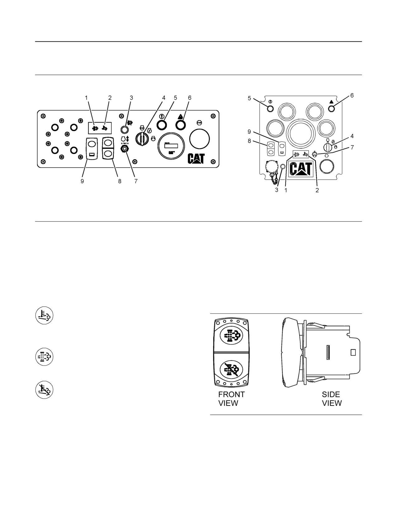
38
SEBU8598
Engine Operation
Diesel Particulate Filter Regeneration
Regeneration Indicator Lamps and Controls
Illustration 30
g02334417
The engine may be equipped with one of the control panels pictured above.
(1) “DPF” Indicator lamp
(4) “START KEY” switch
(8) “REGENERATION” switch
(2) “HIGH EXHAUST TEMPERATURE”
(5) “DIAGNOSTIC” lamp
(9) “HIGH SPEED REGENERATION”
indicator lamp
(6) “SHUTDOWN” lamp
enable switch
(3) “REGENERATION DISABLED”
(7) “IDLE SPEED” switch
indicator lamp
Note: For further information about the monitoring
Regeneration Controls
system, refer to this Operation and Maintenance
Manual, “Monitoring System”.
Regeneration Control Switch
“HIGH EXHAUST SYSTEM
TEMPERATURE (HEST)” - This indicator
lamp illuminates to show that a
regeneration is active. This indicator lamp turns
off when the regeneration is complete.
“DPF” - This indicator lamp illuminates
to show that a regeneration is needed.
This indicator lamp illuminates when the
soot level reaches 80%.
“REGENERATION DISABLED” - This
indicator lamp illuminates to show that a
regeneration has been disabled.
Illustration 31
g02333653
“REGENERATION” control switch
The position of the “REGENERATION” switch in the
side view is the MIDDLE position.
Note: The MIDDLE position of the switch is the
default position for low and high speed regenerations.
Note: Some OEMs use other means of activating a
forced regeneration such as a touch screen interface.
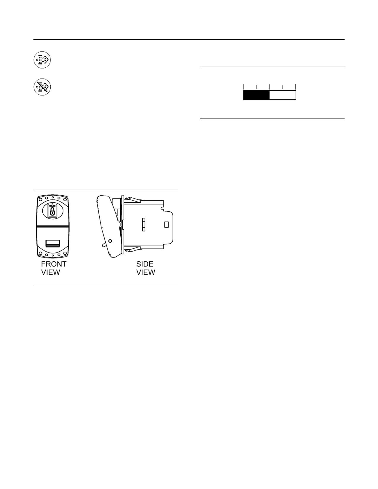
SEBU8598
39
Engine Operation
Diesel Particulate Filter Regeneration
“FORCE REGENERATION” - Press and
Soot Level Monitoring
hold in the top of the switch for 3
seconds to start regeneration.
“DISABLE REGENERATION” - Press
and hold in the bottom of the switch for 3
seconds to disable regeneration.
Note: To re-enable the regeneration, cycle the engine
“START SWITCH KEY” or press and hold in the
“FORCE REGENERATION” switch for 2 seconds.
Illustration 33
g02228033
Note: If the engine “START SWITCH KEY” is cycled
The soot level monitor indicates the level of soot that
while the regeneration system is disabled via the
has accumulated within the DPF. The five marks on
“DISABLE REGENERATION” switch, press and hold
the monitor represent the percentage of soot within
in the “DISABLE REGENERATION” switch for 3
the DPF. The first mark indicates 0% soot level. The
second mark indicates 25% soot level. The third mark
seconds to reinitiate the disable regeneration.
indicates 50% soot level. The fourth mark indicates
75% soot level. The last mark indicates 100% soot
OK to Elevate Idle Switch
level. The soot level monitor may be used to optimize
DPF regenerations based upon the work cycle of the
engine. If operating conditions do not allow for
automatic regeneration, a manual regeneration
should be performed before the soot level gauge
indicates 100%
Note: The soot level monitor may not be applied to all
engines. Some OEM's may also use a different
method of displaying soot load of the DPF. Refer to
OEM operation manual for explanation.
Modes of Regeneration
Automatic
The engine control module (ECM) uses multiple
electrical inputs from the engine to determine the best
Illustration 32
g02333673
time for an automatic regeneration. An automatic
“OK to Elevate Idle Switch” switch
regeneration may take place throughout the operating
The position of the “OK to Elevate Idle Switch”
cycle of the engine. An automatic regeneration may
switch in the side view is the LOCKED position.
start when the engine is at the low idle speed or when
the engine is at normal operating speed. The “HEST”
OK to Elevate Idle Switch - Pressing in and locking
indicator lamp is illuminated when a regeneration is
the “OK to Elevate Idle” switch enables the engine
being performed.
ECM to elevate engine speed automatically when
If an automatic regeneration starts while the engine is
needed. For example, if the engine is running at low
at the low idle speed, the engine may be returned to
idle and a DPF regeneration is activated, having the
normal work at any time. Returning to normal work
“OK to Elevate Idle” switch in the LOCKED position
may stop the regeneration. The ECM will continue to
will allow the engine speed to increase in order for the
monitor inputs to determine the best time to restart
DPF regeneration to occur.
the regeneration.
Interruptions of the regeneration are acceptable. If a
Note: This switch is only available on engines with
regeneration needs to be stopped for any reason,
instrument panels supplied by Cat.
press the DISABLE REGENERATION switch or turn
off the engine.
Note: An automatic adjustment of engine speed may
be noticed during an automatic regeneration. If the
engine is taken to a low idle speed while a
regeneration is occurring, the engine speed may
remain elevated in order for the regeneration to
continue.
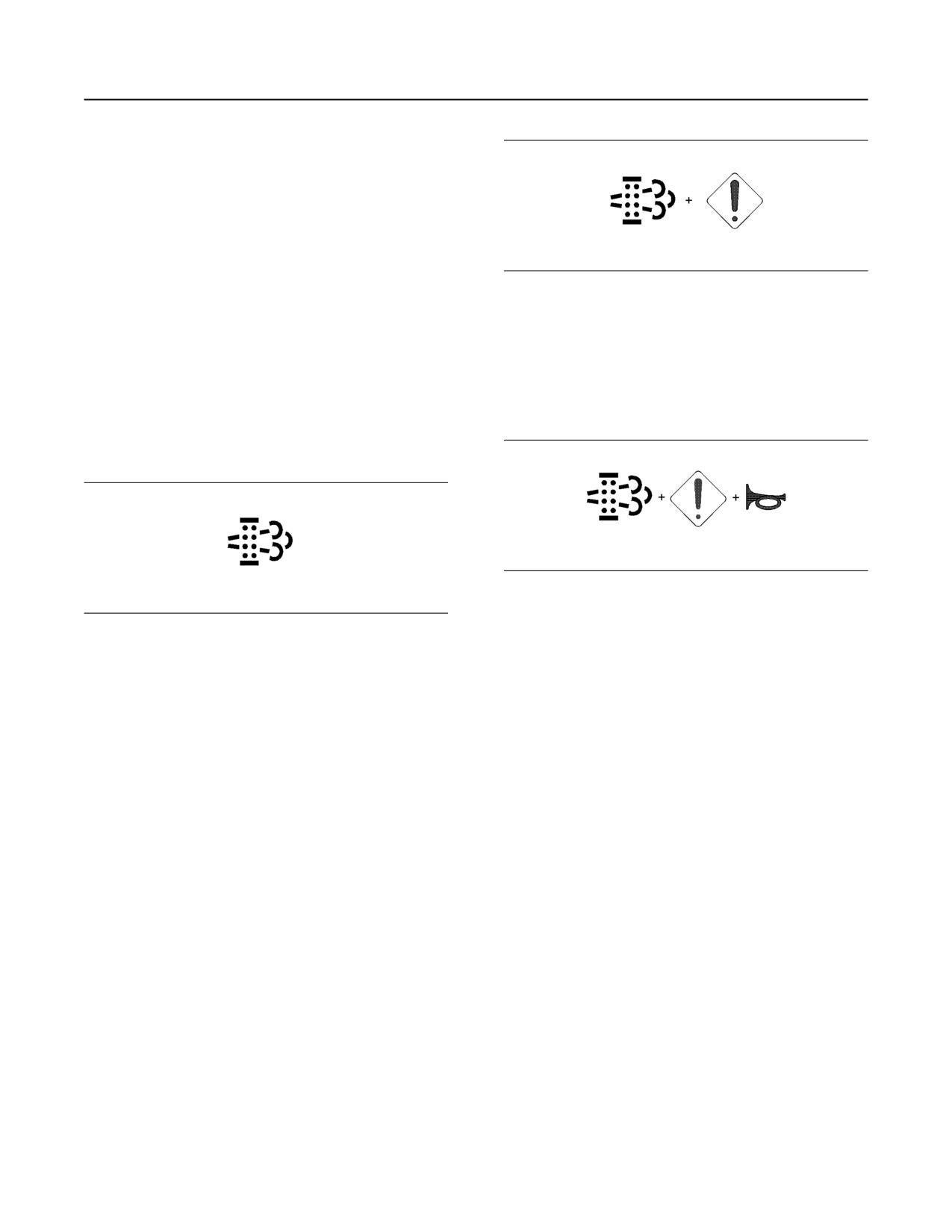
40
SEBU8598
Engine Operation
Engaging the Driven Equipment
Manual
A manual regeneration is initiated by pressing the
“FORCE REGENERATION” switch. A manual
regeneration may be performed at a low idle speed or
during normal engine operation. The soot loading
must be between 15% and 116% for a manual
regeneration to occur while the engine is at a low idle
speed. The soot loading must be between 15% and
105% for a manual regeneration to occur at normal
Illustration 35
g02117259
engine operating speed. The engine coolant
temperature should be at least 40° C (104° F).
The “DPF” indicator lamp illuminates and the
“DIAGNOSTIC” indicator lamp illuminates when the
engine control module (ECM) determines that the
Disabled
amount of soot collected in the DPF has reached a
level that requires a regeneration. Place the engine
When the regeneration system is in disabled mode,
into a low idle state immediately. Initiate a manual
automatic regeneration is not available.
regeneration. The engine power will be derated if the
engine continues to operate.
Regeneration System Warning
Indicators
Illustration 36
g02117261
When the soot load reaches 116%, the
Illustration 34
g02117258
“DIAGNOSTIC” indicator lamp illuminates, the “DPF”
indicator lamp illuminates and the audible horn
The “DPF” indicator lamp illuminates when the DPF
sounds. Not all applications have an audible horn.
soot load is greater than 80%
After 5 minutes of engine operation at 116% of soot
load, the engine is automatically taken to the
A regeneration should be performed as soon as
programmed low idle speed. A manual regeneration
possible. Engine operation may not be allowing
in the low speed region is then required. A complete
an automatic regeneration to occur. A manual
regeneration will unlock the forced low idle speed.
regeneration should be performed as soon as
Cycling the engine “START SWITCH KEY” unlocks
possible.
the forced low idle speed.
The “DPF” indicator lamp will turn off when DPF
After the engine operates at 116% of soot level for 10
regeneration starts.
minutes, all types of regeneration are locked out. A
service regeneration through the CAT ET service tool
Note: In some situations, the “DPF” indicator lamp
is the only form of regeneration allowed.
may remain illuminated when the soot load is below
80%. The illuminated “DPF” indicator lamp indicates
If the engine continues to operate without a
that a complete regeneration has not been
regeneration until a soot level of 140% is reached, the
completed. A complete regeneration reduces the soot
engine shuts down after 30 seconds. The engine may
level to 0%. If the “DPF” indicator lamp remains
be restarted but will only run for 30 seconds at a time
illuminated, perform a regeneration without
before shutting down. At this time, service level
interruption until the soot level is 0%. A complete
regeneration is locked out and the DPF must be
replaced.
regeneration resets the “DPF” indicator lamp.
i04038637
Engaging the Driven
Equipment
SMCS Code: 1000
1. Operate the engine at one-half of the rated rpm,
when possible.
SEBU8598
41
Engine Operation
Fuel Conservation Practices
2. Engage the driven equipment without a load on the
• Observe the service indicator for the air cleaner
equipment, when possible.
frequently, if equipped. Keep the air cleaner
elements clean.
Interrupted starts put excessive stress on the drive
train. Interrupted starts also waste fuel. To get the
•
Do not remove the cover for the air cleaner unless
driven equipment in motion, engage the clutch
the air filter service indicator indicates the need for
smoothly with no load on the equipment. This
cleaning of the filter.
method should produce a start that is smooth and
easy. The engine rpm should not increase and the
•
Maintain a good electrical system.
clutch should not slip.
One bad battery cell will overwork the alternator. This
3. Ensure that the ranges of the gauges are normal
will consume excess power and excess fuel.
when the engine is operating at one-half of the
•
Ensure that the belts are properly adjusted. The
rated rpm. Ensure that all gauges operate properly.
belts should be in good condition.
4. Increase the engine rpm to the rated rpm. Always
•
Ensure that all of the connections of the hoses are
increase the engine rpm to the rated rpm before
tight. The connections should not leak.
the load is applied.
•
Ensure that the driven equipment is in good
5. Apply the load. Begin operating the engine at low
working order.
load. Check the gauges and equipment for proper
operation. After normal oil pressure is reached and
•
Cold engines consume excess fuel. Keep cooling
the temperature gauge begins to move, the engine
system components clean and keep cooling
may be operated at full load. Check the gauges
system components in good repair. Never operate
the engine without water temperature regulators.
and equipment frequently when the engine is
All of these items will help maintain operating
operated under load.
temperatures.
Extended operation at low idle or at reduced load
may cause increased oil consumption and carbon
buildup in the cylinders. This carbon buildup
results in a loss of power and/or poor performance.
i05893104
Fuel Conservation Practices
SMCS Code: 1000; 1250
The efficiency of the engine can affect the fuel
economy. The design and technology used
byCaterpillar in manufacturing provides maximum
fuel efficiency in all applications. Follow the
recommended procedures in order to attain optimum
performance for the life of the engine.
• Avoid spilling fuel.
Fuel expands when the fuel is warmed up. The fuel
may overflow from the fuel tank. Inspect fuel lines for
leaks. Repair the fuel lines, as needed.
• Be aware of the properties of the different fuels.
Use only the recommended fuels.
• Avoid unnecessary operation at no load.
Shut off the engine instead of operating the engine at
no load for long periods of time.
42
SEBU8598
Cold Weather Operation
Radiator Restrictions
There are three major differences between No. 1 and
Cold Weather Operation
No. 2 diesel fuel. No. 1 diesel fuel has the following
properties:
i01646447
• Lower cloud point
Radiator Restrictions
• Lower pour point
SMCS Code: 1353; 1396
• Lower rating of kJ (BTU) per unit volume of fuel
Caterpillar discourages the use of airflow restriction
devices that are mounted in front of radiators. Airflow
When No. 1 diesel fuel is used, a decrease in power
restriction can cause the following conditions:
and in fuel efficiency may be noticed. Other operating
effects should not be experienced.
• High exhaust temperatures
The cloud point is the temperature when a cloud of
• Power loss
wax crystals begins to form in the fuel. These crystals
can cause the fuel filters to plug. The pour point is the
• Excessive fan usage
temperature when diesel fuel will thicken. The diesel
fuel becomes more resistant to flow through fuel
• Reduction in fuel economy
pumps and through fuel lines.
If an airflow restriction device must be used, the
Be aware of these values when diesel fuel is
device should have a permanent opening directly in
purchased. Anticipate the average ambient
line with the fan hub. A centered opening that is
temperature for the engine area. Engines that are
directly in line with the fan hub is specified in order to
fueled in one climate may not operate well if the
prevent an interrupted airflow on the fan blades.
engines are moved to another climate. Problems can
Interrupted airflow on the fan blades could cause a
result due to changes in temperature.
fan failure.
Before troubleshooting for low power or for poor
Caterpillar recommends a warning device for the inlet
performance during cold weather, check the type of
manifold temperature and/or the installation of an inlet
fuel that is being used.
air temperature gauge. The warning device for the
inlet manifold temperature should be set at 75 °C
(167 °F). The inlet manifold air temperature should
i03480664
not exceed 75 °C (167 °F). Temperatures that
exceed this limit can cause power loss and potential
Fuel Related Components in
engine damage.
Cold Weather
i03895851
SMCS Code: 1000; 1250; 1280
Fuel and the Effect from Cold
Fuel Tanks
Weather
Condensation can form in partially filled fuel tanks.
Top off the fuel tanks after you operate the engine.
SMCS Code: 1000; 1250; 1280
Fuel tanks should contain some provision for draining
The following fuels are the grades that are available
water and sediment from the bottom of the tanks.
for Caterpillar engines:
Some fuel tanks use supply pipes that allow water
and sediment to settle below the end of the fuel
• No. 1
supply pipe.
• No. 2
Some fuel tanks use supply lines that take fuel
directly from the bottom of the tank. If the engine is
• Blend of No. 1 and No. 2
equipped with this system, regular maintenance of
the fuel system filter is important.
No. 2 diesel fuel is the most commonly used fuel.
Either No. 1 diesel fuel or a blend of No. 1 and No. 2
is best suited for cold weather operation.
Fuel Filters
Cold fuel may contain wax which will block the fuel
Note: No. 2 diesel fuel can begin to form crystals at
filters. One of the following changes can prevent
approximately -9° C (15° F).
problems in many conditions: a change in the location
Quantities of No. 1 diesel fuel are limited. No. 1 diesel
of fuel filters and/or supply lines and the addition of
fuels are usually available during the months of the
insulation.
winter in the colder climates. During cold weather
operation, if No. 1 diesel fuel is not available, use No.
2 diesel fuel, if necessary.
SEBU8598
43
Cold Weather Operation
Fuel Related Components in Cold Weather
Fuel Heaters
In extreme temperatures, heating of the fuel may be
required to prevent the filters from plugging. There
are several types of fuel heaters that are available.
These systems may prevent filter waxing problems
without the use of de-icers or cold flow improvers.
These systems may be ineffective when the fuel
contains a large amount of dirt or of water. A fuel
heater should be installed so that the fuel is heated
before flowing into the fuel filter.
Note: Only use properly sized fuel heaters that are
controlled by thermostats or use fuel heaters that are
self-regulated. Thermostatically controlled fuel
heaters generally heat fuel to 15.5° C (60° F). Do not
use fuel heaters in warm temperatures.
Note: Do not allow the fuel to get too warm, because
fuel above 52°C (125°F) will affect the power output
of the engine. Never exceed 75°C (165°F) with
straight distillate fuel. The high fuel temperatures also
affect the fuel viscosity. When the fuel viscosity falls
below 1.4 cSt at the fuel injection pump, pump
damage may occur.
Overheating the fuel or the fuel filter can result in
personal injury and/or damage to the engine. Use
extreme care and caution for heating of the fuel
and/or the fuel filter.
Select a fuel heater that is mechanically simple, yet
adequate for the application. The fuel heater should
also prevent overheating of the fuel. Disconnect the
fuel heater or deactivate the fuel heater in warm
weather. An unacceptable loss of fuel viscosity and
engine power will occur if the fuel supply temperature
is allowed to become too hot.
For additional information on fuel heaters, consult
your Caterpillar dealer.
44
SEBU8598
Engine Stopping
Manual Stop Procedure
• If necessary, perform minor adjustments. Repair
Engine Stopping
any leaks and tighten any loose bolts.
i04315380
• Note the service hour meter reading. Perform the
maintenance that is in the Operation and
Manual Stop Procedure
Maintenance Manual, “Maintenance Interval
Schedule”.
SMCS Code: 1000; 7418
• Fill the fuel tank to prevent accumulation of
NOTICE
moisture in the fuel. Do not overfill the fuel tank.
Stopping the engine immediately after it has been
• Allow the engine to cool. Check the coolant level.
working under load can result in overheating and ac-
Maintain the cooling system at 13 mm (0.5 inch)
celerated wear of the engine components.
from the bottom of the pipe for filling.
If the engine has been operating at high rpm and/or
Note: Only use coolant that is recommended in this
high loads, run at low idle for at least three minutes to
Operation and Maintenance Manual, “Fluid
reduce and stabilize internal engine temperature be-
fore stopping the engine.
Recommendations” article. Failure to do so may
result in engine damage.
Avoiding hot engine shutdowns will maximize turbo-
charger shaft and bearing life.
• If freezing temperatures are expected, check the
coolant for proper antifreeze protection. The
cooling system must be protected against freezing
Note: Individual applications have different control
to the lowest expected outside temperature. Add
systems. Ensure that the shutoff procedures are
the proper coolant/water mixture, if necessary.
understood. Use the following general guidelines in
order to stop the engine.
• Perform all required periodic maintenance on all
driven equipment. This maintenance is outlined in
1. Remove the load from the engine so that the
the instructions from the OEM.
engine has no more than 30% power.
2. Run the engine at the programmed low idle speed
for at least 3 minutes.
3. After the cool down period, turn the start switch to
the OFF position.
i04137729
After Stopping Engine
SMCS Code: 1000
Note: After operation, allow 10 minutes for the engine
oil to return to the oil pan before checking the engine
oil level.
• Check the crankcase oil level. Maintain the oil level
between the “ADD” mark and the “FULL” mark
on the oil level gauge.
Note: Only use oil that is recommended in this
Operation and Maintenance Manual, “Fluid
Recommendations” article. Failure to do so may
result in engine damage.
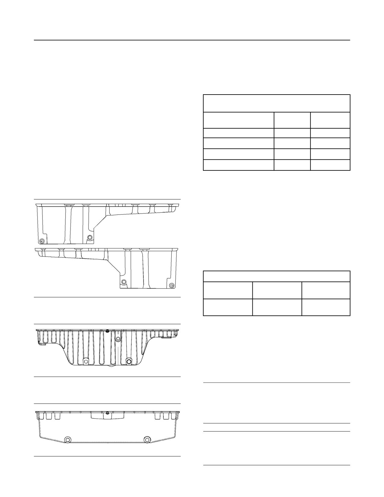
SEBU8598
45
Maintenance Section
Refill Capacities
The refill capacities for the engine crankcase reflect
Maintenance Section
the approximate capacity of the crankcase or sump
plus standard oil filters. Auxiliary oil filter systems will
require additional oil. Refer to the OEM specifications
Refill Capacities
for the capacity of the auxiliary oil filter.
Table 4
i04133774
C15 and C18 Industrial Engines
Approximate Refill Capacities
Refill Capacities
Engine with 1
Engine with 2
Oil Sump(1)
SMCS Code: 1000; 1348; 1395; 7560
Filter
Filters
Refer to this Operation and Maintenance Manual,
“Fluid Recommendations” for information about the
Standard pan
34 L (36 qt)
36 L (38 qt)
fluids which are acceptable for this engine.
Center pan
60 L (63 qt)
62 L (66 qt)
Note: Refer to Special Publication, SEBU6251,
Deep pan
68 L (72 qt)
70 L (74 qt)
“CaterpillarCommercial Diesel Engine Fluids
Recommendations” for additional information.
(1) These values are approximate capacities for the crankcase oil
sump which include the standard oil filters that are installed at
the factory. Engines with auxiliary oil filters will require additional
Lubricant Refill Capacity
oil. Refer to the OEM specifications for the capacity of the auxili-
ary oil filter.
Coolant Refill Capacity
To maintain the cooling system, the total cooling
system capacity must be known. The capacity of the
total cooling system will vary. The capacity will
depend on the size of the radiator (capacity). Table 5
should be completed by the customer for the
maintenance of the cooling system.
Table 5
Approximate Capacity of the Cooling System
Compartment or
Liters
Quarts
System
Illustration 37
g02300456
Total Cooling System
Standard pan
(1)
(1) The total cooling system capacity includes the following compo-
nents:the engine block, the radiator and all coolant hoses and
lines.
i05489209
Fluid Recommendations
SMCS Code: 1280; 1348; 1395; 7560
Illustration 38
g02300473
Center pan
NOTICE
Every attempt is made to provide accurate, up-to-date
information. By the use of this document, you agree
that Caterpillar Inc. is not responsible for errors or
omissions.
NOTICE
These recommendations are subject to change with-
out prior notice. Contact your Caterpillar dealer for the
most up to date recommendations.
Illustration 39
g02300474
Deep pan
46
SEBU8598
Refill Capacities
Fluid Recommendations
Refer to Special Publication, SEBU6251, “Cat
• Diesel Particulate Filters (DPF)
Commercial Diesel Engine Fluids Recommendations”
for additional information.
• Diesel Oxidation Catalysts (DOC)
Refer to this Operation and Maintenance Manual,
• Selective Catalytic Reduction (SCR)
“Severe Service Application” for information about
operating an engine in a severe service application.
• Lean NOx Traps (LNT)
Note: Instructions for the installation of the filter are
Other systems may apply.
printed on the side of each Cat spin-on filter. For
filters that are not Cat filters, refer to the installation
instructions that are provided by the supplier of the
filter.
Diesel Engine Oil
Cat DEO (Diesel Engine Oil)
Due to significant variations in the quality and in the
performance of commercially available oils,
Caterpillar makes the following recommendations:
• Cat DEO-ULS (Diesel Engine Oil Ultra Low
Sulfur) (SAE 5W-40)
• Cat DEO-ULS (Diesel Engine Oil Ultra Low
Sulfur) (SAE 10W-30)
• Cat DEO-ULS (Diesel Engine Oil Ultra Low
Sulfur) (SAE 15W-40)
Engine Oil
Cat oils have been developed and tested in order to
provide the full performance and life that has been
designed and built into Cat engines.
Cat DEO-ULS or oils that meet the Cat ECF-3
specification and the API CJ-4 are required for use in
the applications listed below. Cat DEO-ULS and oils
meeting Cat ECF-3 specification and the API CJ-4
and ACEA E9 oil categories have been developed
with limited sulfated ash, phosphorus, and sulfur.
These chemical limits are designed to maintain the
expected aftertreatment devices life, performance,
and service interval. If oils meeting the Cat ECF-3
specification and the API CJ-4 specifications are not
available, oils meeting ACEA E9 may be used. ACEA
E9 oils meet the chemical limits designed to maintain
aftertreatment device life. ACEA E9 oils are validated
using some but not all ECF-3 and API CJ-4 standard
engine performance tests. Consult your oil supplier
when considering use of an oil that is not Cat ECF-3
or API CJ-4 qualified.
Failure to meet the listed requirements will damage
aftertreatment-equipped engines and can negatively
impact the performance of the aftertreatment devices.
The Diesel Particulate Filter (DPF) will plug sooner
and require more frequent DPF ash service intervals.
Typical aftertreatment systems include the following:
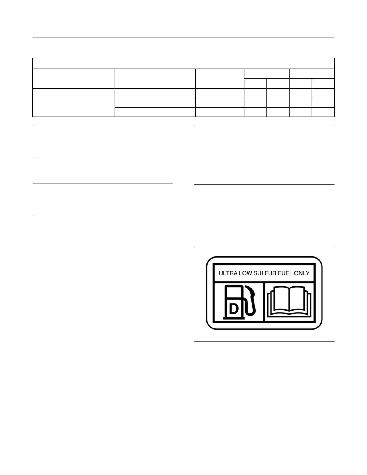
SEBU8598
47
Refill Capacities
Fluid Recommendations
Table 6
Lubricant Viscosities for Ambient Temperatures
Oil Type and Performance
°C
°F
Compartment or System
Oil Viscosities
Requirements
Min
Max
Min
Max
Cat DEO-ULS Cold Weather
SAE 0W-40
-40
40
-40
104
Engine Crankcase
Cat DEO-ULS
SAE 10W-30
-18
40
0
104
Cat DEO-ULS
SAE 15W-40
-9.5
50
15
122
NOTICE
NOTICE
Oil Renewal systems should not be used in engines
Always use a designated pump for oil sampling, and
equipped with aftertreatment systems. Reduced life
use a separate designated pump for coolant sam-
or damage to the aftertreatment may occur.
pling. Using the same pump for both types of samples
may contaminate the samples that are being drawn.
This contaminate may cause a false analysis and an
incorrect interpretation that could lead to concerns by
S·O·S Services Oil Analysis
both dealers and customers.
NOTICE
These recommendations are subject to change with-
Refer to Special Publication, SEBU6251, “Cat
Commercial Diesel Engine Fluids Recommendations”
out prior notice. Contact your Caterpillar dealer for the
in order to obtain additional information about S·O·S
most up to date recommendations.
Services oil analysis. You can also contact your local
Cat dealer in order to obtain additional information
about the S·O·S Services Oil Analysis program.
Caterpillar has developed a maintenance tool that
evaluates oil degradation. the maintenance
Diesel Fuel Recommendations
management also detects the early signs of wear on
internal components. The Cat tool for oil analysis is
called S·O·S Oil Analysis and the tool is part of the
S·O·S Services program. S·O·S Oil Analysis divides
oil analysis into four categories:
• Component wear rate
• Oil condition
• Oil contamination
• Identification of oil
These four types of analysis are used to monitor the
condition of your equipment. The four types of
analysis will also help you identify potential problems.
A properly administered S·O·S Oil Analysis program
will reduce repair costs and the program will lessen
Illustration 40
g02157153
the impact of downtime.
NACD Film
The S·O·S Oil Analysis program uses a wide range of
tests to determine the condition of the oil and the
lubricated compartment. Guidelines that are based on
experience and a correlation to failures have been
established for these tests. Exceeding one or more of
these guidelines could indicate serious fluid
degradation or a pending component failure. A
trained person at your Cat dealership should make
the final analysis.
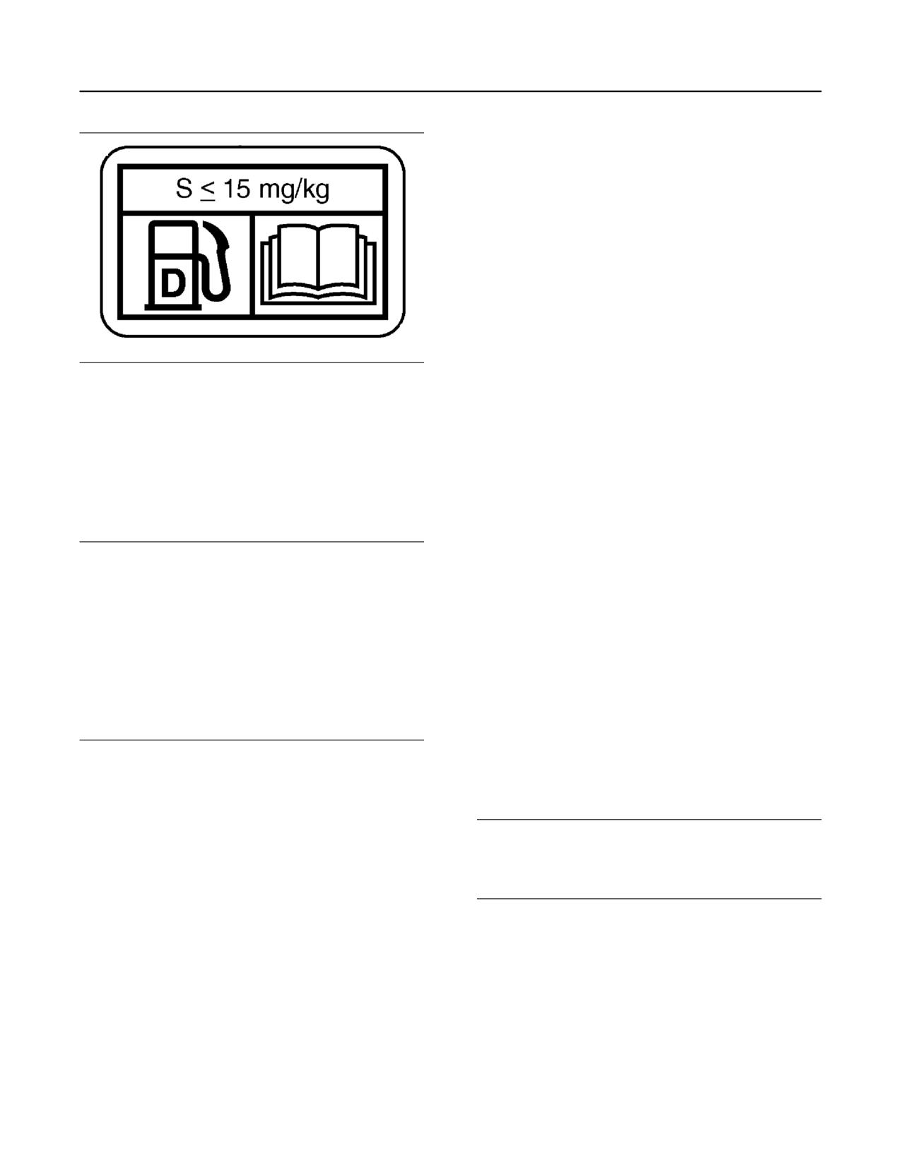
48
SEBU8598
Refill Capacities
Fluid Recommendations
• Shorten the time interval between
aftertreatment device service intervals (cause
the need for more frequent service intervals)
• Adversely impact the performance and life of
aftertreatment devices (cause loss of
performance)
• Reduce regeneration intervals of
aftertreatment devices
• Reduce engine efficiency and durability.
• Increase the wear.
• Increase the corrosion.
Illustration 41
g02052934
EAME Film
• Increase the deposits.
Diesel fuel must meet “Cat Specification for Distillate
• Lower fuel economy
Fuel” and the latest versions of “ASTM D975” or “EN
590” in order to ensure optimum engine performance.
• Shorten the time period between oil drain intervals
Refer to Special Publication, SEBU6251, “Cat
(more frequent oil drain intervals).
Commercial Diesel Engine Fluids Recommendations”
for the latest fuel information and for Cat fuel
• Increase overall operating costs.
specification. This manual may be found on the Web
at Safety.Cat.com.
Failures that result from the use of improper fuels are
not Cat factory defects. Therefore the cost of repairs
would not be covered by a Cat warranty.
NOTICE
Ultra Low Sulfur Diesel (ULSD) fuel 0.0015 percent
Cat does not require the use of ULSD in off road and
(≤15 ppm (mg/kg)) sulfur is required by regulation for
machine applications that are not Tier 4/Stage IIIB
use in engines certified to nonroad Tier 4 standards
certified engines. ULSD is not required in engines
(U.S. EPA Tier 4 certified) and that are equipped with
that are not equipped with after treatment devices.
exhaust aftertreatment systems.
For Tier 4/Stage IIIB/Stage IV certified engines
always follow operating instructions. Fuel tank inlet
European ULSD 0.0010 percent (≤10ppm (mg/kg))
labels are installed in order to ensure that the correct
sulfur fuel is required by regulation for use in engines
fuels are used.
certified to European nonroad Stage IIIB and newer
standards and are equipped with exhaust aftertreat-
Refer to Special Publication, SEBU6251, “Cat
ment systems.
Commercial Diesel Engine Fluids Recommendations”
for more details about fuels, lubricants, and Tier 4
requirements. This manual may be found on the Web
Misfueling with fuels of higher sulfur level can
at Safety.Cat.com.
have the following negative effects:
Lubricating Grease
NOTICE
These recommendations are subject to change with-
out prior notice. Contact your Caterpillar dealer for the
most up to date recommendations.
Cat provides various greases that vary in
performance from a moderate performance to high
performance. Cat greases service the entire line of
Cat products in the wide variety of climates
throughout the world. From this variety of Cat grease
products, you can find a Cat grease that will meet or
exceed the performance requirements of most
engines.
SEBU8598
49
Refill Capacities
Fluid Recommendations
The performance requirements of your engine must
NOTICE
be determined before you select any Cat grease.
Frequently check the specific gravity of the coolant for
Consult the recommendations for greases that are
proper freeze protection or for anti-boil protection.
made by the OEM for the equipment. Then, consult
with your Cat dealer for a list of greases that have the
performance specifications and the available sizes of
containers.
NOTICE
Never operate an engine without water temperature
Note: Always choose grease that meets or exceeds
regulators in the cooling system. Water temperature
the recommendations that are specified by the
regulators help to maintain the engine coolant at the
equipment manufacturer for the application.
proper operating temperature. Cooling system prob-
lems can develop without water temperature
If choosing a single grease to use for all of the
regulators.
equipment at one site is necessary , always choose a
grease that meets or exceeds the requirements of the
most demanding application. Remember that the
products which barely meet the minimum
NOTICE
performance requirements can be expected to
Never use water alone as a coolant. Water alone is
produce the minimum lives of your parts. False
corrosive at engine operating temperatures. In addi-
economy is being used if a grease is purchased with
tion, water alone does not provide adequate protec-
the lowest cost as the only consideration. Instead,
tion against boiling or freezing.
use the grease that yields the lowest total operating
cost. This cost should be based on an analysis that
includes the costs of parts, labor, downtime, and the
NOTICE
cost of the amount of grease that is required.
All Cat engines that are equipped with a Cat NOx Re-
duction System require a minimum of 50 percent gly-
Note: Purge all of the old grease from a joint before
col to help prevent cavitation damage and boiling of
you change from one type of grease to another type
the engine coolant. These engines include Tier 4
of grease. Some greases are not chemically
engines.
compatible with other greases. Consult your supplier
in order to determine if the greases are compatible.
The following two coolants are used in Cat Diesel
If you are not certain that the old grease is compatible
Engines :
with the new grease, purge the old grease from the
system before applying the new grease.
Preferred - Cat ELC (Extended Life Coolant) or a
commercial extended life coolant that meets the Cat
Note: All Cat greases are chemically compatible
Engine Coolant-1 (EC-1) specification.
with each other. Mixing of Cat greases does not
result in an adverse chemical reaction. However,
mixing of Cat greases may result in reduced
Acceptable - Cat DEAC (Diesel Engine Antifreeze/
Coolant) or a commercial heavy-duty coolant that
performance.
meets “ASTM D4985”, or “ASTM D6210”
Non-Cat commercial greases are as a group second
specifications
choice greases. Within this grouping of second
choice greases, there are tiered levels of
Note: Cat DEAC does not require a treatment with a
performance. For more information, refer to Special
Supplemental Coolant Additive (SCA) at the initial fill.
Publication, SEBU6251, “Cat Commercial Diesel
Engines Fluids Recommendations”.
However, a commercial heavy-duty coolant that only
meets the “ASTM D4985” specification will require a
Coolant
treatment with an SCA at the initial fill. A commercial
heavy-duty coolant that meets the “ASTM D6210”
specification will not require a treatment with an SCA
NOTICE
at the initial fill. Read the label or the instructions that
These recommendations are subject to change with-
are provided by the manufacturer of the commercial
out prior notice. Contact your Caterpillar dealer for the
heavy-duty coolant.
most up to date recommendations.
Note: These coolants will require a treatment with a
supplemental coolant additive on a maintenance
NOTICE
basis.
Never add coolant to an overheated engine. Engine
damage could result. Allow the engine to cool first.

50
SEBU8598
Refill Capacities
Fluid Recommendations
Table 7
For more information, refer to Special Publication,
SEBU6251, “Cat Commercial Diesel Engines Fluids
Service Life Before Flushing and Before Refilling
Recommendations”
Coolant
Service Life(1)
Cat ELC
12,000 hours, or 6 years
Commercial coolant that meets the
6000 hours, or 6 years
Cat EC-1 specification
Cat DEAC
3000 hours, or 3 years
Commercial Heavy-Duty Coolant
that meets “ASTM D4985” or
3000 hours, or 1 year
“ASTM D6210”
(1) Use the interval that occurs first.
Note: Add the Cat ELC Extender at the halfway
point of the coolant change interval.
Note: These coolant change intervals are only
possible with annual S·O·S Services Level 2 coolant
sampling and analysis.
S·O·S Services Coolant Analysis
Table 8
Recommended Interval
Type of
Level 1
Level 2
Coolant
Every 500 Hours
(1)
Every 2000 Hours
DEAC
(2)
or Yearly(1)(3)
ELC
Optional(3)
Yearly(3)
(1) This interval is recommended for the sampling of all convention-
al heavy-duty coolant.
(2) This interval is also recommended for the sampling of a com-
mercial coolant that meets the Cat (Engine Coolant specifica-
tion - 1) requirement.
(3) The Level 2 coolant analysis should be performed sooner if a
problem is suspected or identified.
Testing the engine coolant is important to ensure that
the engine is protected from internal cavitation and
from corrosion. The analysis also tests the ability of
the coolant to protect the engine from boiling and
from freezing. The S·O·S Coolant Analysis can be
performed at your Cat dealer. Cat S·O·S Coolant
Analysis is the best way to monitor the condition of
your coolant and your cooling system. S·O·S Coolant
Analysis is a program that is based on periodic
samples.
NOTICE
Always use a designated pump for oil sampling, and
use a separate designated pump for coolant sam-
pling. Using the same pump for both types of samples
may contaminate the samples that are being drawn.
This contaminate may cause a false analysis and an
incorrect interpretation that could lead to concerns by
both dealers and customers.
SEBU8598
51
Maintenance Recommendations
System Pressure Release
Do not loosen the high pressure fuel lines in order to
Maintenance
remove air pressure from the fuel system.
Recommendations
Engine Oil
i02909163
To relieve pressure from the lubricating system, turn
off the engine.
System Pressure Release
SMCS Code: 1250; 1300; 1350; 5050
i05182568
Coolant System
Welding on Engines with
Electronic Controls
SMCS Code: 1000
Pressurized system: Hot coolant can cause seri-
ous burn. To open cap, stop engine, wait until ra-
NOTICE
diator is cool. Then loosen cap slowly to relieve
Because the strength of the frame may decrease,
the pressure.
some manufacturers do not recommend welding onto
a chassis frame or rail. Consult the OEM of the equip-
ment or your Cat dealer regarding welding on a chas-
To relieve the pressure from the coolant system, turn
sis frame or rail.
off the engine. Allow the cooling system pressure cap
to cool. Remove the cooling system pressure cap
slowly in order to relieve pressure.
Proper welding procedures are necessary in order to
avoid damage to the engine Electronic Control
Fuel System
Module (ECM), Clean Emissions Module (CEM),
sensors, and associated components. When
To relieve the pressure from the fuel system, turn off
possible, remove the component from the unit and
the engine.
then weld the component. If removal of the
component is not possible, the following procedure
must be followed when you weld on a unit that is
High Pressure Fuel Lines (If Equipped)
equipped with a Caterpillar Electronic Engine. The
following procedure is considered to be the safest
procedure to weld on a component. This procedure
should provide a minimum risk of damage to
electronic components.
Contact with high pressure fuel may cause fluid
penetration and burn hazards. High pressure fuel
NOTICE
spray may cause a fire hazard. Failure to follow
Do not ground the welder to electrical components
these inspection, maintenance and service in-
such as the ECM or sensors. Improper grounding can
structions may cause personal injury or death.
cause damage to the drive train, the bearings, hy-
draulic components, electrical components, and other
The high pressure fuel lines are the fuel lines that are
components.
between the high pressure fuel pump and the high
pressure fuel manifold and the fuel lines that are
Do not ground the welder across the centerline of the
package. Improper grounding could cause damage to
between the fuel manifold and cylinder head. These
the bearings, the crankshaft, the rotor shaft, and other
fuel lines are different from fuel lines on other fuel
systems.
components.
This is because of the following differences:
Clamp the ground cable from the welder to the com-
ponent that will be welded. Place the clamp as close
• The high pressure fuel lines are constantly
as possible to the weld. This will help reduce the pos-
sibility of damage.
charged with high pressure.
• The internal pressures of the high pressure fuel
Note: Perform the welding in areas that are free from
lines are higher than other types of fuel system.
explosive hazards.
Before any service or repair is performed on the
engine fuel lines, perform the following tasks:
1. Stop the engine. Turn the switched power to the
OFF position.
1. Stop the engine.
2. Wait for ten minutes.
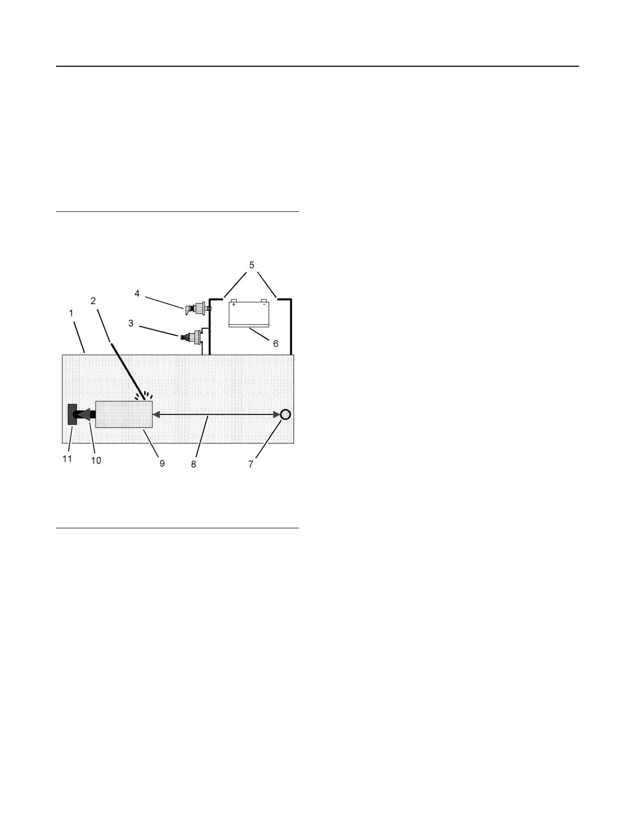
52
SEBU8598
Maintenance Recommendations
Severe Service Application
2. Disconnect the negative battery cable from the
Note: If electrical/electronic components are used as
battery. If a battery disconnect switch is provided,
a ground for the welder, or electrical/electronic
open the switch.
components are located between the welder ground
and the weld, current flow from the welder could
3. Disconnect the J1/P1 and J2/P2 connectors from
severely damage the component.
the ECM and. Disconnect the wiring from the CEM.
5. Protect the wiring harness from welding debris and
Move the harnesses to a position that will not allow
spatter.
the harnesses to contact with any of the ECM,
CEM, or pins accidentally.
6. Use standard welding practices to weld the
materials.
i04889860
Severe Service Application
SMCS Code: 1000
An engine which operates outside of normal
conditions is operating in a severe service
application.
An engine that operates in a severe service
application may need more frequent maintenance
intervals in order to maximize the following
conditions:
• Reliability
• Service life
The number of individual applications cause the
impossibility of identifying all of the factors which may
contribute to severe service operation. Consult your
Cat dealer for the unique maintenance that may be
necessary for your engine.
An application is a severe service application if any of
the following conditions apply:
Severe Environmental Factors
Illustration 42
g01075639
• Frequent operation in dirty air
Use the example above. The current flow from the
welder to the ground clamp of the welder will not
• Frequent operation at an altitude which is above
damage any associated components.
1525 m (5000 ft)
(1) Engine
(2) Welding electrode
• Frequent operation in ambient temperatures which
(3) Keyswitch in the OFF position
(4) Battery disconnect switch in the open position
are above 32° C (90° F)
(5) Disconnected battery cables
(6) Battery
• Frequent operation in ambient temperatures which
(7) Electrical/Electronic component
are below 0° C (32° F)
(8) Minimum distance between the component that is being welded
and any electrical/electronic component
(9) The component that is being welded
(10) Current path of the welder
(11) Ground clamp for the welder
4. Connect the welding ground cable directly to the
part that will be welded. Place the ground cable as
close as possible to the weld in order to reduce the
possibility of welding current damage to bearings,
hydraulic components, electrical components, and
ground straps.
SEBU8598
53
Maintenance Recommendations
Severe Service Application
Severe Operating Conditions
Improper Maintenance Procedures
(Maintenance Procedures Which
•
Frequent operation with inlet air which has a
corrosive content
May Contribute to a Severe Service
Application)
•
Operation with inlet air which has a combustible
content
•
Inadequate maintenance of fuel storage tanks from
causes such as excessive water, sediment, and
•
Operation which is outside of the intended
microorganism growth.
application
•
Extending maintenance intervals beyond the
•
Operation with a plugged fuel filter
recommended intervals
•
Extended operation at low idle (more than 20% of
•
Using fluids which are not recommended in
hours)
Special Publication, SEBU6251, “Cat Commercial
•
Frequent cold starts at temperatures below 0° C
Diesel Engine Fluids Recommendations”
(32° F)
•
Extending maintenance intervals for changing the
•
Frequent dry starts (starting after more than 72
engine oil and engine coolant without S·O·S
hours of shutdown)
validation
•
Frequent hot shutdowns (shutting down the engine
•
Extending maintenance intervals for changing air
without the minimum of 2 minutes to 5 minutes of
filters, oil filters, and fuel filters
cool down time)
•
Failure to use a water separator
•
Operation above the engine rated speed
•
Using filters which are not recommended by
•
Operation below the peak torque speed
Special Publication, PEWJ0074, “2008 Cat Filter
and Fluid Application Guide”
•
Operating with fuel which does not meet the
standards for distillate diesel fuel as stated in
Special Publication, SEBU6251, “Cat Commercial
Diesel Engine Fluids Recommendations”,
“Distillate Diesel Fuel”
•
Operating with a blend of distillate fuel which
contains more than 20 percent biodiesel
54
SEBU8598
Maintenance Recommendations
Maintenance Interval Schedule
i06002369
“Fuel System - Prime”
81
“Fuel Tank Water and Sediment - Drain”
84
Maintenance Interval Schedule
“Radiator - Clean”
92
(C15 Engines)
SMCS Code: 1000; 4450; 7500
Daily
S/N: LDN1-Up
“Air Tank Moisture and Sediment - Drain”
61
Ensure that all safety information, warnings, and
“Coolant Level - Check”
69
instructions are read and understood before any
operation or any maintenance procedures are
“Driven Equipment - Check”
72
performed.
“Engine Air Cleaner Service Indicator - Inspect”
76
The user is responsible for the performance of all
“Engine Oil Level - Check”
77
maintenance which includes the following items:
performing all adjustments, using proper lubricants,
“Fuel System Primary Filter/Water Separator -
fluids, and filters and replacing old components with
Drain”
81
new components due to normal wear and aging .
“Power Take-Off Clutch - Check”
91
Failure to adhere to proper maintenance intervals and
procedures may result in diminished performance of
“Walk-Around Inspection”
92
the product and/or accelerated wear of components.
Every 250 Service Hours
Before each consecutive interval is performed, all
maintenance from the previous intervals must be
“Engine Oil Sample - Obtain”
78
performed.
“Grounding Stud - Inspect/Clean/Tighten”
86
Choose the interval that occurs first in order to
determine the correct maintenance interval: fuel
consumption, service hours and calendar time .
Every 500 Service Hours
Products that operate in severe operating conditions
may require more frequent maintenance.
“Battery Electrolyte Level - Check”
62
All of the following will affect the oil change interval:
“Belts - Inspect/Replace”
63
operating conditions, fuel type, oil type and size of the
“Coolant Sample (Level 1) - Obtain”
69
oil sump . Scheduled oil sampling analyzes used oil in
order to determine if the oil change interval is suitable
“Cooling System Supplemental Coolant Additive
for your specific engine.
(SCA) - Test/Add”
70
Refer to this Operation and Maintenance Manual,
“Engine Oil and Filter - Change”
78
“Engine Oil and Filter - Change” in order to determine
the oil change interval that is suitable for your specific
“Fuel System Primary Filter (Water Separator)
engine.
Element - Replace”
82
To determine the maintenance intervals for the
“Fuel System Secondary Filter - Replace”
83
overhauls, refer to this Operation and Maintenance
Manual, “Maintenance Recommendations” .
“Hoses and Clamps - Inspect/Replace”
86
When Required
Every 2000 Service Hours
“Battery - Recycle”
61
“Air Shutoff - Test”
60
“Battery - Replace”
61
“Fumes Disposal Filter Element - Replace”
84
“Battery or Battery Cable - Disconnect”
62
Every 2000 Service Hours or 1 Year
“Engine - Clean”
73
“Coolant Sample (Level 2) - Obtain”
70
“Engine Air Cleaner Element (Dual Element/Box
Type) - Replace”
73
Every 2500 Service Hours
“Engine Air Cleaner Element (Single Element) -
“Compression Brake - Inspect/Adjust/Replace”
64
Inspect/Clean/Replace”
75
“Electronic Unit Injector - Check/Replace”
72
“Engine Storage Procedure - Check”
80
“Engine Valve Lash - Check”
80
SEBU8598
55
Maintenance Recommendations
Maintenance Interval Schedule
“Valve Actuators - Check”
92
Failure to adhere to proper maintenance intervals and
procedures may result in diminished performance of
Every 3000 Service Hours or 3
the product and/or accelerated wear of components.
Years
Before each consecutive interval is performed, all
maintenance from the previous intervals must be
“Coolant (DEAC) - Change”
64
performed.
“Electronic Unit Injector - Check/Replace”
72
Choose the interval that occurs first in order to
determine the correct maintenance interval: fuel
Every 4000 Service Hours
consumption, service hours and calendar time .
Products that operate in severe operating conditions
“Air Compressor - Check”
60
may require more frequent maintenance.
“Engine Mounts - Inspect”
77
All of the following will affect the oil change interval:
operating conditions, fuel type, oil type and size of the
“Starting Motor - Inspect”
92
oil sump . Scheduled oil sampling analyzes used oil in
order to determine if the oil change interval is suitable
Every 5000 Service Hours
for your specific engine.
“ARD Spark Plug - Replace”
59
Refer to this Operation and Maintenance Manual,
“Engine Oil and Filter - Change” in order to determine
“Diesel Particulate Filter - Clean/Replace”
71
the oil change interval that is suitable for your specific
engine.
“Fuel Priming Pump - Replace”
81
To determine the maintenance intervals for the
Every 6000 Service Hours or 3
overhauls, refer to this Operation and Maintenance
Manual, “Maintenance Recommendations” .
Years
When Required
“Coolant Extender (ELC) - Add”
68
“Battery - Recycle”
61
Every 12 000 Service Hours or 6
“Battery - Replace”
61
Years
“Coolant (ELC) - Change”
66
“Battery or Battery Cable - Disconnect”
62
“Engine - Clean”
73
Every 585 000 L (154 540 US gal) of
Fuel or 10 000 Service Hours
“Engine Air Cleaner Element (Dual Element/Box
Type) - Replace”
73
“Overhaul Considerations”
88
“Engine Air Cleaner Element (Single Element) -
Inspect/Clean/Replace”
75
i06002281
“Engine Storage Procedure - Check”
80
Maintenance Interval Schedule
“Fuel System - Prime”
81
(C15 Engines With Ratings
“Fuel Tank Water and Sediment - Drain”
84
Greater Than 579 hp)
SMCS Code: 1000; 4450; 7500
“Radiator - Clean”
92
S/N: LDN1-Up
Daily
Ensure that all safety information, warnings, and
“Air Tank Moisture and Sediment - Drain”
61
instructions are read and understood before any
“Coolant Level - Check”
69
operation or any maintenance procedures are
performed.
“Driven Equipment - Check”
72
The user is responsible for the performance of all
“Engine Air Cleaner Service Indicator - Inspect”
76
maintenance which includes the following items:
performing all adjustments, using proper lubricants,
“Engine Oil Level - Check”
77
fluids, and filters and replacing old components with
new components due to normal wear and aging .
“Fuel System Primary Filter/Water Separator -
Drain”
81
56
SEBU8598
Maintenance Recommendations
Maintenance Interval Schedule
“Power Take-Off Clutch - Check”
91
Every 5000 Service Hours
“Walk-Around Inspection”
92
“ARD Spark Plug - Replace”
59
Every 250 Service Hours
“Diesel Particulate Filter - Clean/Replace”
71
“Engine Oil Sample - Obtain”
78
“Fuel Priming Pump - Replace”
81
“Grounding Stud - Inspect/Clean/Tighten”
86
Every 6000 Service Hours or 3
Years
Initial 500 Service Hours
“Coolant Extender (ELC) - Add”
68
“Engine Valve Lash - Check”
80
Every 12 000 Service Hours or 6
Every 500 Service Hours
Years
“Battery Electrolyte Level - Check”
62
“Coolant (ELC) - Change”
66
“Belts - Inspect/Replace”
63
Every 585 000 L (154 540 US gal) of
“Coolant Sample (Level 1) - Obtain”
69
Fuel or 10 000 Service Hours
“Cooling System Supplemental Coolant Additive
“Overhaul Considerations”
88
(SCA) - Test/Add”
70
“Engine Oil and Filter - Change”
78
i06002437
“Fuel System Primary Filter (Water Separator)
Maintenance Interval Schedule
Element - Replace”
82
(C18 Engines With Ratings
“Fuel System Secondary Filter - Replace”
83
Greater Than 760 HP)
“Hoses and Clamps - Inspect/Replace”
86
SMCS Code: 1000; 4450; 7500
Every 2000 Service Hours
S/N: BDN1-Up
“Air Shutoff - Test”
60
Ensure that all safety information, warnings, and
“Fumes Disposal Filter Element - Replace”
84
instructions are read and understood before any
operation or any maintenance procedures are
Every 2000 Service Hours or 1 Year
performed.
The user is responsible for the performance of all
“Coolant Sample (Level 2) - Obtain”
70
maintenance which includes the following items:
performing all adjustments, using proper lubricants,
Every 2500 Service Hours
fluids, and filters and replacing old components with
new components due to normal wear and aging .
“Compression Brake - Inspect/Adjust/Replace”
64
Failure to adhere to proper maintenance intervals and
“Electronic Unit Injector - Check/Replace”
72
procedures may result in diminished performance of
the product and/or accelerated wear of components.
“Engine Valve Lash - Check”
80
Before each consecutive interval is performed, all
“Valve Actuators - Check”
92
maintenance from the previous intervals must be
performed.
Every 3000 Service Hours or 3
Years
Choose the interval that occurs first in order to
determine the correct maintenance interval: fuel
“Coolant (DEAC) - Change”
64
consumption, service hours and calendar time .
Products that operate in severe operating conditions
may require more frequent maintenance.
Every 4000 Service Hours
All of the following will affect the oil change interval:
“Air Compressor - Check”
60
operating conditions, fuel type, oil type and size of the
oil sump . Scheduled oil sampling analyzes used oil in
“Engine Mounts - Inspect”
77
order to determine if the oil change interval is suitable
“Starting Motor - Inspect”
92
for your specific engine.
SEBU8598
57
Maintenance Recommendations
Maintenance Interval Schedule
Refer to this Operation and Maintenance Manual,
“Coolant Sample (Level 1) - Obtain”
69
“Engine Oil and Filter - Change” in order to determine
the oil change interval that is suitable for your specific
“Cooling System Supplemental Coolant Additive
engine.
(SCA) - Test/Add”
70
To determine the maintenance intervals for the
“Engine Oil and Filter - Change”
78
overhauls, refer to this Operation and Maintenance
Manual, “Maintenance Recommendations” .
“Fuel System Primary Filter (Water Separator)
Element - Replace”
82
When Required
“Fuel System Secondary Filter - Replace”
83
“Battery - Recycle”
61
“Hoses and Clamps - Inspect/Replace”
86
“Battery - Replace”
61
Every 2000 Service Hours
“Battery or Battery Cable - Disconnect”
62
“Air Shutoff - Test”
60
“Engine - Clean”
73
“Fumes Disposal Filter Element - Replace”
84
“Engine Air Cleaner Element (Dual Element/Box
Type) - Replace”
73
Every 2000 Service Hours or 1 Year
“Engine Air Cleaner Element (Single Element) -
“Coolant Sample (Level 2) - Obtain”
70
Inspect/Clean/Replace”
75
Every 2500 Service Hours
“Engine Storage Procedure - Check”
80
“Compression Brake - Inspect/Adjust/Replace”
64
“Fuel System - Prime”
81
“Electronic Unit Injector - Check/Replace”
72
“Fuel Tank Water and Sediment - Drain”
84
“Engine Valve Lash - Check”
80
“Radiator - Clean”
92
“Valve Actuators - Check”
92
Daily
Every 3000 Service Hours or 3
“Air Tank Moisture and Sediment - Drain”
61
Years
“Coolant Level - Check”
69
“Coolant (DEAC) - Change”
64
“Driven Equipment - Check”
72
Every 4000 Service Hours
“Engine Air Cleaner Service Indicator - Inspect”
76
“Air Compressor - Check”
60
“Engine Oil Level - Check”
77
“Engine Mounts - Inspect”
77
“Fuel System Primary Filter/Water Separator -
Drain”
81
“Starting Motor - Inspect”
92
“Power Take-Off Clutch - Check”
91
Every 6000 Service Hours or 3
“Walk-Around Inspection”
92
Years
Every 250 Service Hours
“Coolant Extender (ELC) - Add”
68
“Engine Oil Sample - Obtain”
78
Every 12 000 Service Hours or 6
“Grounding Stud - Inspect/Clean/Tighten”
86
Years
Initial 500 Service Hours
“Coolant (ELC) - Change”
66
“Engine Valve Lash - Check”
80
Every 760 000 L (200 770 US gal) of
Fuel or 10 000 Service Hours
Every 500 Service Hours
“Overhaul Considerations”
88
“Battery Electrolyte Level - Check”
62
“Belts - Inspect/Replace”
63
58
SEBU8598
Maintenance Recommendations
Maintenance Interval Schedule
i06002391
“Fuel System - Prime”
81
“Fuel Tank Water and Sediment - Drain”
84
Maintenance Interval Schedule
“Radiator - Clean”
92
(C18 Engines)
SMCS Code: 1000; 4450; 7500
Daily
S/N: BDN1-Up
“Air Tank Moisture and Sediment - Drain”
61
Ensure that all safety information, warnings, and
“Coolant Level - Check”
69
instructions are read and understood before any
operation or any maintenance procedures are
“Driven Equipment - Check”
72
performed.
“Engine Air Cleaner Service Indicator - Inspect”
76
The user is responsible for the performance of all
“Engine Oil Level - Check”
77
maintenance which includes the following items:
performing all adjustments, using proper lubricants,
“Fuel System Primary Filter/Water Separator -
fluids, and filters and replacing old components with
Drain”
81
new components due to normal wear and aging .
“Power Take-Off Clutch - Check”
91
Failure to adhere to proper maintenance intervals and
procedures may result in diminished performance of
“Walk-Around Inspection”
92
the product and/or accelerated wear of components.
Every 250 Service Hours
Before each consecutive interval is performed, all
maintenance from the previous intervals must be
“Engine Oil Sample - Obtain”
78
performed.
“Grounding Stud - Inspect/Clean/Tighten”
86
Choose the interval that occurs first in order to
determine the correct maintenance interval: fuel
consumption, service hours and calendar time .
Every 500 Service Hours
Products that operate in severe operating conditions
may require more frequent maintenance.
“Battery Electrolyte Level - Check”
62
All of the following will affect the oil change interval:
“Belts - Inspect/Replace”
63
operating conditions, fuel type, oil type and size of the
“Coolant Sample (Level 1) - Obtain”
69
oil sump . Scheduled oil sampling analyzes used oil in
order to determine if the oil change interval is suitable
“Cooling System Supplemental Coolant Additive
for your specific engine.
(SCA) - Test/Add”
70
Refer to this Operation and Maintenance Manual,
“Engine Oil and Filter - Change”
78
“Engine Oil and Filter - Change” in order to determine
the oil change interval that is suitable for your specific
“Fuel System Primary Filter (Water Separator)
engine.
Element - Replace”
82
To determine the maintenance intervals for the
“Fuel System Secondary Filter - Replace”
83
overhauls, refer to this Operation and Maintenance
Manual, “Maintenance Recommendations” .
“Hoses and Clamps - Inspect/Replace”
86
When Required
Every 2000 Service Hours
“Battery - Recycle”
61
“Air Shutoff - Test”
60
“Battery - Replace”
61
“Fumes Disposal Filter Element - Replace”
84
“Battery or Battery Cable - Disconnect”
62
Every 2000 Service Hours or 1 Year
“Engine - Clean”
73
“Coolant Sample (Level 2) - Obtain”
70
“Engine Air Cleaner Element (Dual Element/Box
Type) - Replace”
73
Every 2500 Service Hours
“Engine Air Cleaner Element (Single Element) -
“Compression Brake - Inspect/Adjust/Replace”
64
Inspect/Clean/Replace”
75
“Electronic Unit Injector - Check/Replace”
72
“Engine Storage Procedure - Check”
80
“Engine Valve Lash - Check”
80
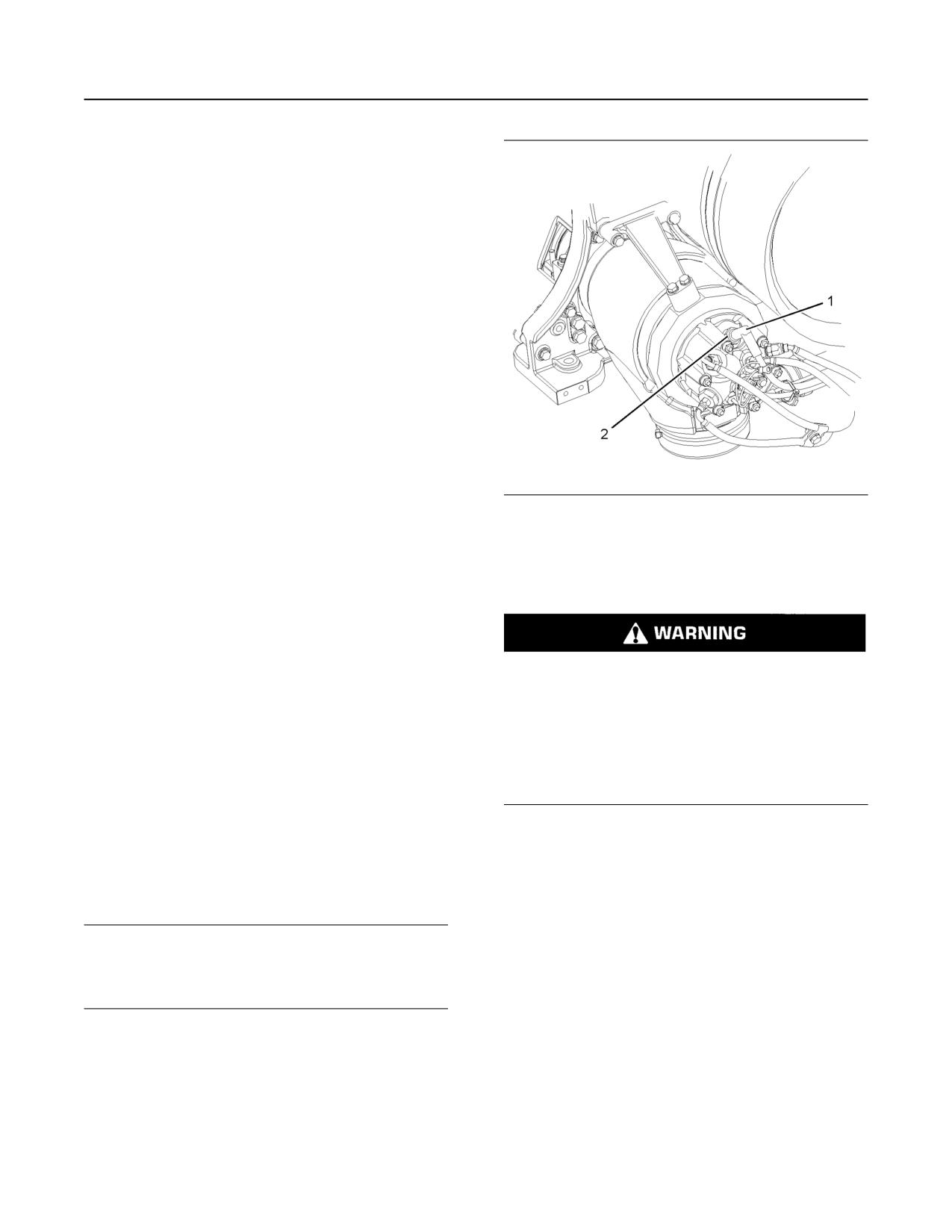
SEBU8598
59
Maintenance Recommendations
ARD Spark Plug - Replace
“Valve Actuators - Check”
92
Every 3000 Service Hours or 3
Years
“Coolant (DEAC) - Change”
64
Every 4000 Service Hours
“Air Compressor - Check”
60
“Engine Mounts - Inspect”
77
“Starting Motor - Inspect”
92
Every 5000 Service Hours
“ARD Spark Plug - Replace”
59
“Diesel Particulate Filter - Clean/Replace”
71
“Fuel Priming Pump - Replace”
81
Illustration 43
g02139990
Every 6000 Service Hours or 3
(1) Wiring harness
Years
(2) Spark plug
“Coolant Extender (ELC) - Add”
68
1. Remove wire harness (1) from spark plug (2).
Every 12 000 Service Hours or 6
Years
“Coolant (ELC) - Change”
66
Personal injury can result from air pressure.
Every 760 000 L (200 770 US gal) of
Personal injury can result without following prop-
Fuel or 10 000 Service Hours
er procedure. When using pressure air, wear a
protective face shield and protective clothing.
“Overhaul Considerations”
88
The maximum air pressure for cleaning purposes
i04880449
must be reduced to 205 kPa (30 psi) when the air
nozzle is deadheaded.
ARD Spark Plug - Replace
2. Debris may have collected in the spark plug well.
(If Equipped)
Thoroughly remove any debris. Use compressed
SMCS Code: 1555-510
air. The maximum air pressure for cleaning
purposes must be below 205 kPa (30 psi). Ensure
that the area around the spark plug is clean and
Removing the Spark Plug
free of dirt and debris.
NOTICE
3. Use a deep well socket and a breaker bar to loosen
If the engine is running or the key is in the ON position
the spark plug. If necessary, see your Caterpillar
the ARD plug will continue to fire. Turn the key to the
dealer for the part number of the socket. After the
OFF position before servicing the ARD plug.
spark plug has been loosened, use the socket to
remove the spark plug by hand in order to detect
problems with the threads. After the spark plug has
been removed, inspect the used spark plug and
the gasket.
If the spark plug could not be removed by hand, clean
the threads with a 305-2389 brush. This tool
scrapes debris from the seat and from the threads.
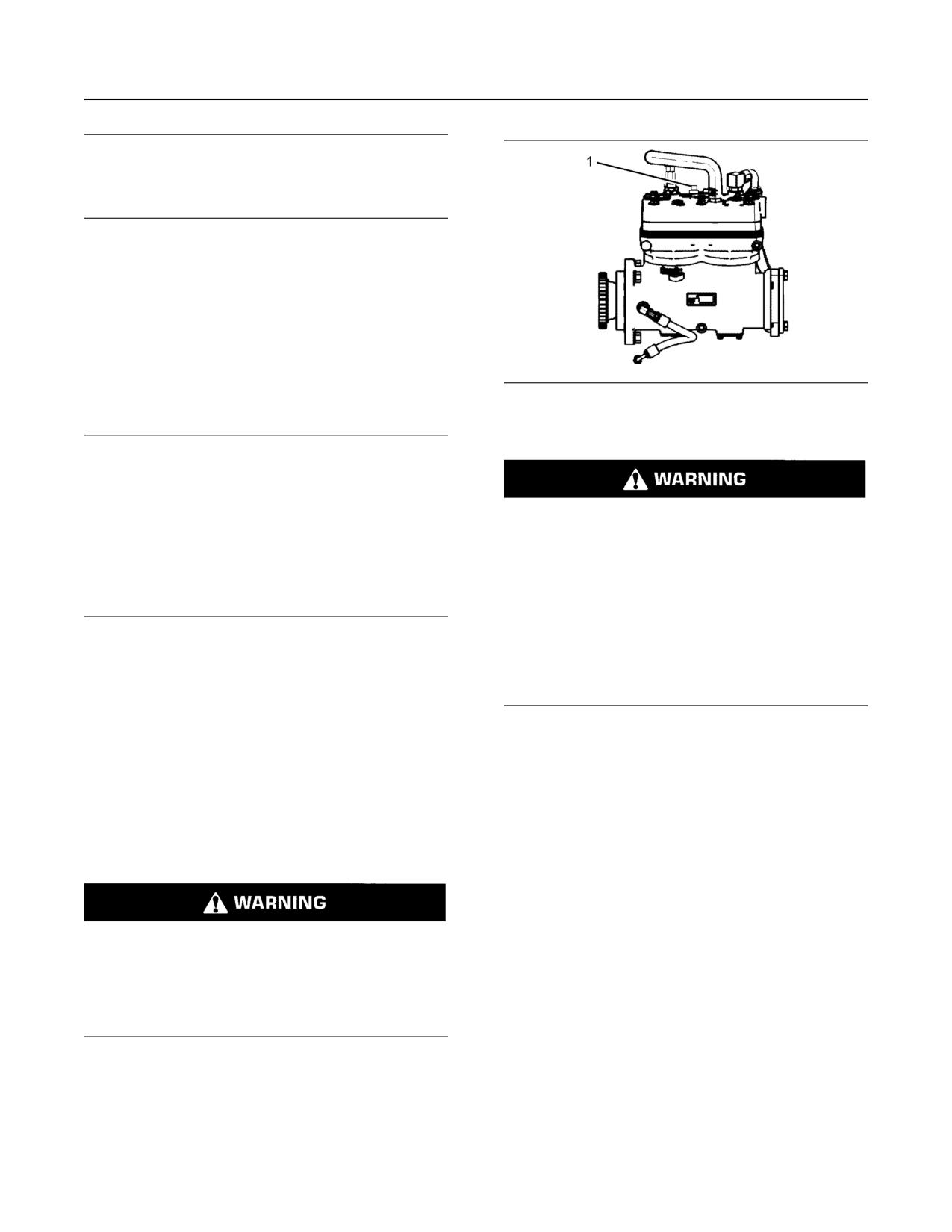
60
SEBU8598
Maintenance Recommendations
Air Compressor - Check
NOTICE
Do not use a thread tap. A thread tap will remove met-
al unnecessarily. The threads could be stripped and
the combustion group could be damaged.
Installing the Spark Plug
Note: Do not use anti-seize compound on the spark
plug. Most of the heat is transferred through the
threads and the seat area of the spark plug. Contact
of the metal surfaces must be maintained in order to
provide the heat transfer that is required.
1. Ensure that the spark plug is clean and free of dirt
Illustration 44
g01212654
and oil.
Typical example
(1) Pressure relief valve
NOTICE
Do not overtighten the spark plug. The shell can be
cracked and the gasket can be deformed. The metal
can deform and the gasket can be damaged. The
If the air compressor pressure relief valve that is
shell can be stretched. This will loosen the seal that is
mounted in the air compressor cylinder head is
between the shell and the insulator, allowing combus-
bypassing compressed air, there is a malfunction
tion pressure to blow past the seal. Serious damage
in the air system, possibly ice blockage. Under
to the engine can occur.
these conditions, your engine may have insuffi-
Use the proper torque.
cient air for normal brake operation.
Do not operate the engine until the reason for the
2. Install the spark plug by hand until the spark plug
air bypass is identified and corrected. Failure to
contacts the ARD. Torque the spark plug to the
heed this warning could lead to property damage,
personal injury, or death to the operator or
proper specification. Refer to Specifications,
bystanders.
“Spark Plug” for the proper torque specification.
3. Connect the wiring harness.
The function of the pressure relief valve is to bypass
air when there is a malfunction in the system for the
air compressor.
i03966490
The pressure relief valve for the air compressor
Air Compressor - Check
releases air at 1723 kPa (250 psi). If the pressure
relief valve for the air compressor exhausts, all
(If equipped)
personnel should be at a safe distance away from the
SMCS Code: 1803-535
air compressor. All personnel should also stay clear
of the air compressor when the engine is operating
and the air compressor is exposed.
Refer to the Service Manual or refer to the OEM
Do not disconnect the air line from the air com-
specifications in order to find information concerning
pressor governor without purging the air brake
the air compressor. Consult your Caterpillar dealer
and the auxiliary air systems. Failure to purge the
for assistance.
air brake and the auxiliary air systems before re-
moving the air compressor and/or the air lines
i05341564
could cause personal injury.
Air Shutoff - Test
SMCS Code: 1078-081
To ensure that the air shutoff valve always shuts
down when the engine ingests gaseous fumes,
perform the test below at each oil change. A test
failure can indicate wear in the block off plate to valve
body interface and/or the bearing system.
SEBU8598
61
Maintenance Recommendations
Air Tank Moisture and Sediment - Drain
1. Place engine at low idle speed. Ensure all
1. Open the drain valve that is on the bottom of the air
accessories that are normally used for the
tank. Allow the moisture and sediment to drain.
application are in use, like a fan, or power takeoffs.
2. Close the drain valve.
2. Actuate the air shutoff manually. On electrical
3. Check the air supply pressure. The air starting
operator air shutoffs, utilize an applicable power
motor requires a minimum of 620 kPa (90 psi) of
supply or jumper cables from the battery to
air pressure to operate properly. The maximum air
energize the air shut-off solenoid. Ensure that the
pressure must not exceed 1550 kPa (225 psi).
solenoid receives only a momentary signal to
The normal air pressure will be 758 to 965 kPa
prevent overheating. On hydraulic operator air
(110 to 140 psi).
shutoffs, found on some hazardous location units,
actuate by pulling the emergency stop handle.
i02039199
3. Ensure that air shutoff was actuated and that the
engine comes to a complete stop.
Battery - Recycle
SMCS Code: 1401-005; 1401-510; 1401-535; 1401-
Note: As every application has different parasitic
561; 1401
loads and inertia, the duration for the problem to
occur cannot be specified. However, if the engine
Always recycle a battery. Never discard a battery.
stumbles or attempts to continue running, these
Return used batteries to one of the following
symptoms may be an indication that worn
locations:
components may need replacement.
• A battery supplier
If additional help is needed, contact the Dealer
Solution Network.
• An authorized battery collection facility
NOTICE
• A recycling facility
Actuating the air shutoff valve may result in oil leak-
age past the shaft seal in some cases. Repeated ac-
i01878164
tuation of the air shutoff valve during loaded operation
of the engine can result in mechanical damage to the
Battery - Replace
turbocharger and reduce turbocharger life.
SMCS Code: 1401-510
i00847451
Air Tank Moisture and
Batteries give off combustible gases which can
explode. A spark can cause the combustible
Sediment - Drain
gases to ignite. This can result in severe personal
injury or death.
(If Equipped)
SMCS Code: 1466-543-M&S
Ensure proper ventilation for batteries that are in
an enclosure. Follow the proper procedures in or-
Moisture and sediment in the air starting system can
der to help prevent electrical arcs and/or sparks
cause the following conditions:
near batteries. Do not smoke when batteries are
serviced.
• Freezing
• Corrosion of internal parts
• Malfunction of the air starting system
The battery cables or the batteries should not be
removed with the battery cover in place. The bat-
tery cover should be removed before any servic-
ing is attempted.
When opening the drain valve, wear protective
Removing the battery cables or the batteries with
gloves, a protective face shield, protective cloth-
the cover in place may cause a battery explosion
ing, and protective shoes. Pressurized air could
resulting in personal injury.
cause debris to be blown and result in personal
injury.
62
SEBU8598
Maintenance Recommendations
Battery Electrolyte Level - Check
1. Switch the engine to the OFF position. Remove all
2. Check the condition of the electrolyte with the
electrical loads.
245-5829 Coolant Battery Tester Refractometer.
2. Turn off any battery chargers. Disconnect any
3. Keep the batteries clean.
battery chargers.
Clean the battery case with one of the following
3. The NEGATIVE “-” cable connects the NEGATIVE
cleaning solutions:
“-” battery terminal to the NEGATIVE “-” terminal
• A mixture of 0.1 kg (0.2 lb) of baking soda and
on the starter motor. Disconnect the cable from the
1 L (1 qt) of clean water
NEGATIVE “-” battery terminal.
• A mixture of 0.1 L (0.11 qt) of ammonia and 1 L
4. The POSITIVE “+” cable connects the POSITIVE
(1 qt) of clean water
“+” battery terminal to the POSITIVE “+” terminal
on the starting motor. Disconnect the cable from
Thoroughly rinse the battery case with clean water.
the POSITIVE “+” battery terminal.
Use a fine grade of sandpaper to clean the
terminals and the cable clamps. Clean the items
Note: Always recycle a battery. Never discard a
until the surfaces are bright or shiny. DO NOT
battery. Return used batteries to an appropriate
remove material excessively. Excessive removal of
recycling facility.
material can cause the clamps to not fit properly.
5. Remove the used battery.
Coat the clamps and the terminals with 5N-5561
Silicone Lubricant, petroleum jelly or MPGM.
6. Install the new battery.
i01492654
Note: Before the cables are connected, ensure that
Battery or Battery Cable -
the engine start switch is OFF.
7. Connect the cable from the starting motor to the
Disconnect
POSITIVE “+” battery terminal.
SMCS Code: 1401; 1402-029
8. Connect the cable from the NEGATIVE “-”
terminal on the starter motor to the NEGATIVE “-”
battery terminal.
The battery cables or the batteries should not be
removed with the battery cover in place. The bat-
i02601752
tery cover should be removed before any servic-
ing is attempted.
Battery Electrolyte Level -
Removing the battery cables or the batteries with
Check
the cover in place may cause a battery explosion
SMCS Code: 1401-535-FLV
resulting in personal injury.
When the engine is not run for long periods of time or
when the engine is run for short periods, the batteries
1. Turn the start switch to the OFF position. Turn the
may not fully recharge. Ensure a full charge in order
ignition switch (if equipped) to the OFF position
to help prevent the battery from freezing.
and remove the key and all electrical loads.
2. Disconnect the negative battery terminal at the
battery that goes to the start switch. Ensure that
All lead-acid batteries contain sulfuric acid which
the cable cannot contact the terminal. When four
can burn the skin and clothing. Always wear a
12 volt batteries are involved, the negative side of
face shield and protective clothing when working
two batteries must be disconnected.
on or near batteries.
3. Tape the leads in order to help prevent accidental
starting.
1. Remove the filler caps. Maintain the electrolyte
level to the “FULL” mark on the battery.
4. Proceed with necessary system repairs. Reverse
the steps in order to reconnect all of the cables.
If the addition of water is necessary, use distilled
water. If distilled water is not available use clean
water that is low in minerals. Do not use artificially
softened water.
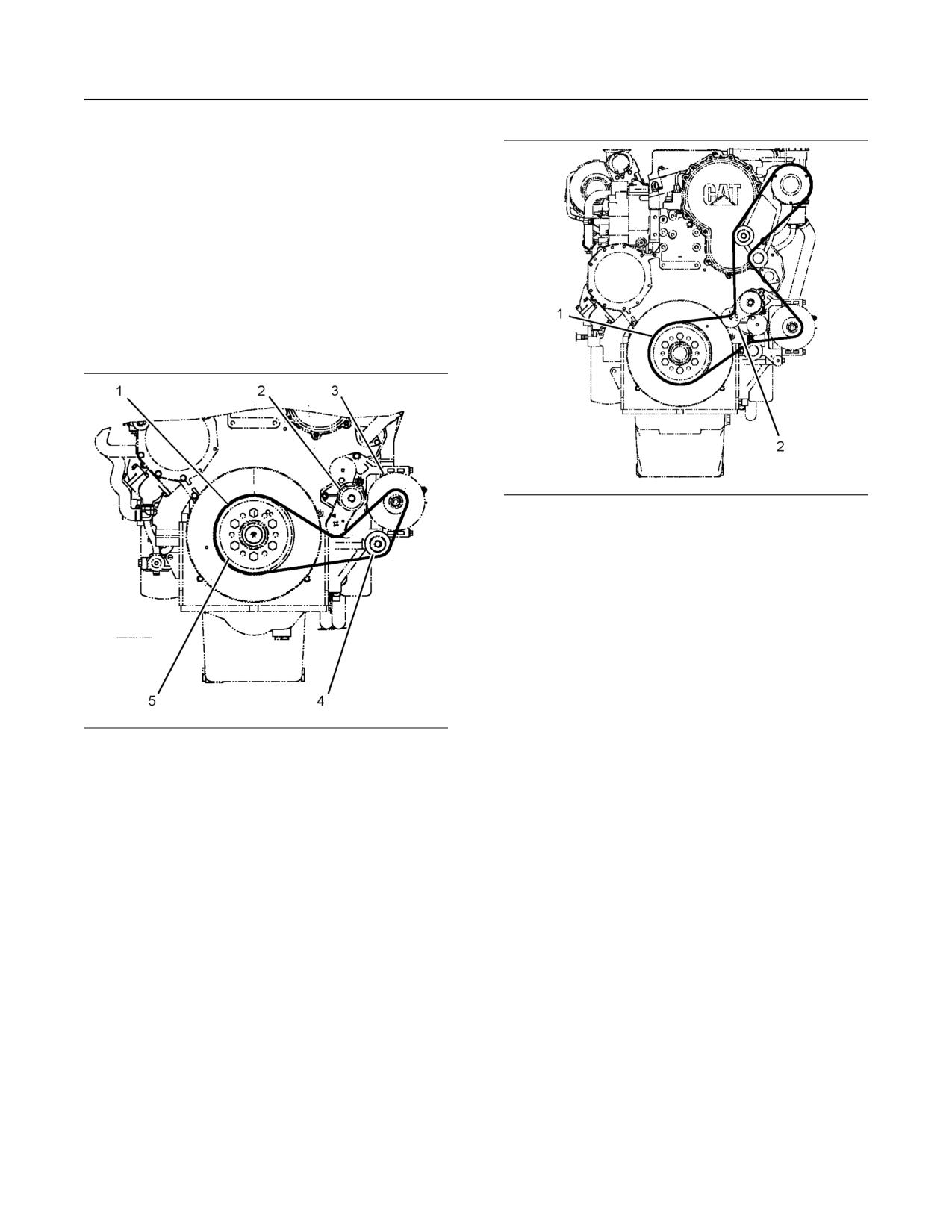
SEBU8598
63
Maintenance Recommendations
Belts - Inspect/Replace
i04322187
Belts - Inspect/Replace
(If Equipped)
SMCS Code: 1397-040; 1397-510
The engine may be equipped with one of the
following types of belts and belt tensioners.
Single Belt
The belt on the engine may look like the belt in
Illustration 45 or like the belt in Illustration 45 .
Illustration 46
g02294634
View of the front of a C15 or a C18 Industrial Engine
(1) Belt
(2) Belt tensioner
For maximum engine performance and maximum
utilization of your engine, inspect the belts for wear
and for cracking. Replace the belts, if necessary.
To replace the belt, perform the following steps:
1. Insert a ratchet with a square drive into the square
hole that is located in the tensioner for the belt.
Rotate the tensioner clockwise in order to relieve
Illustration 45
g02294633
tension on the belt. Remove the belt.
View of the front of a C15 or a C18 Industrial Engine
2. Install the new belt correctly, as shown. Be sure
(1) Belt
that the belt is fully seated on the pulleys. The
(2) Belt tensioner
(3) Alternator
correct tension will automatically be applied when
(4) Idler pulley
the ratchet is removed.
(5) Crankshaft pulley
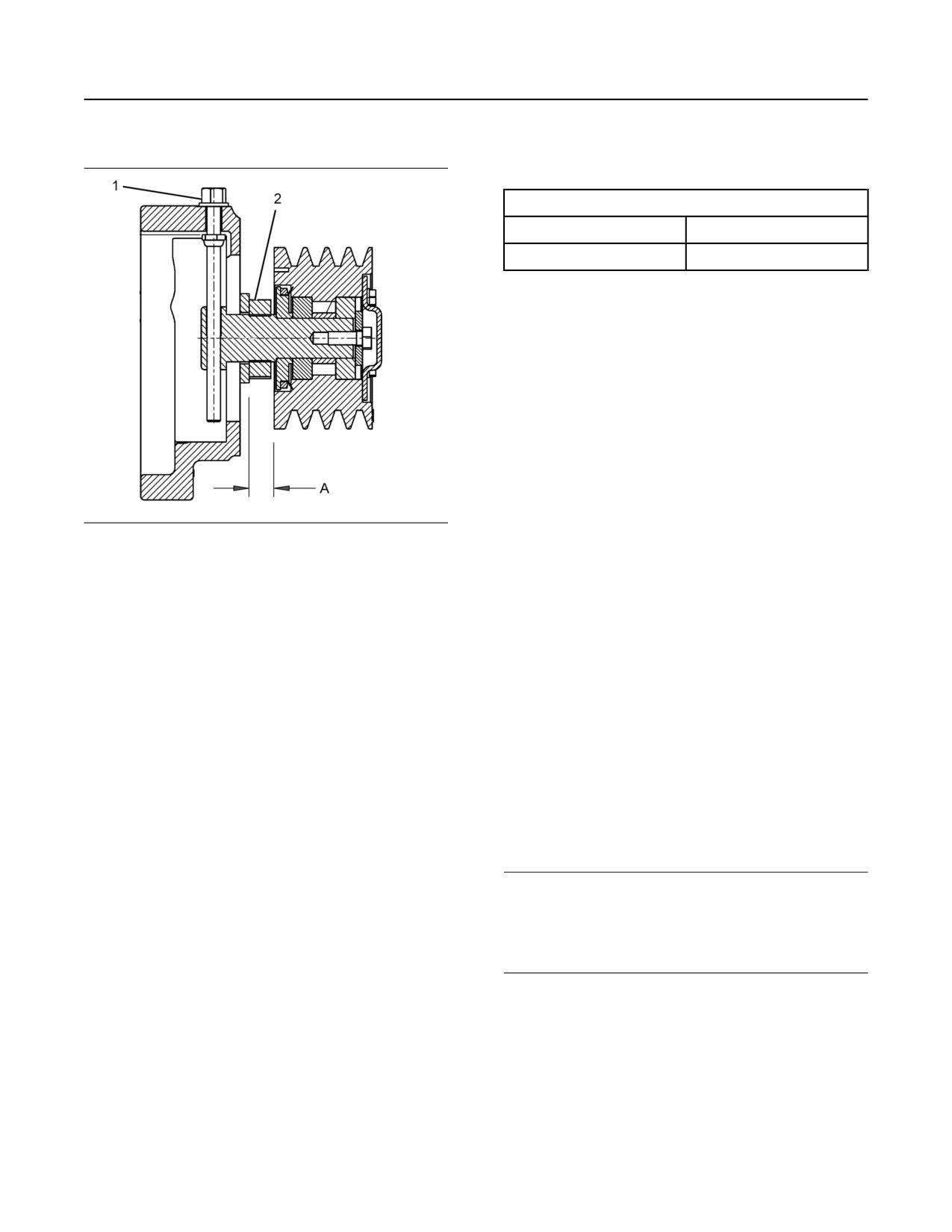
64
SEBU8598
Maintenance Recommendations
Compression Brake - Inspect/Adjust/Replace
Two or More Belts
5. Tighten the jam nut to a torque of 200 ± 25 N·m
(148 ± 18 lb ft)
Table 9
Fan Drive Belt Adjustment
Belt Tension (Initial)
Belt Tension (Used)(1)
801 ± 44 N (180 ± 10 lb)
378 ± 44 N (85 ± 10 lb)
(1) Belt with over 30 minutes of operation at a rated speed
Belt Adjustment
Repeat steps 1, 4, and 5 from the belt replacement
procedure.
i03965390
Compression Brake - Inspect/
Adjust/Replace
SMCS Code: 1119-025; 1119-040; 1119-510
Contact your Cat dealer for the proper procedure.
Illustration 47
g02478261
Belt tensioner
i04156977
(1) Adjustment bolt
(2) 46 mm (1-13/16 inch) jamming locknut (jam nut)
(A) 22 mm (0.87 inch)
Coolant (DEAC) - Change
SMCS Code: 1350-070; 1395-044
Inspection of the Belts
Clean the cooling system and flush the cooling
Inspect the fan drive belts for wear and for cracking.
system before the recommended maintenance
Replace the belts if the belts are not in good
interval if the following conditions exist:
condition.
• The engine overheats frequently.
Belt Replacement
• Foaming is observed.
For applications that require multiple drive belts,
• The oil has entered the cooling system and the
replace the drive belts in matched sets. Replacing
coolant is contaminated.
one drive belt of a matched set will cause the new
drive belt to carry more load because the older drive
• The fuel has entered the cooling system and the
belts are stretched. The additional load on the new
coolant is contaminated.
drive belt could cause the new drive belt to fail.
Use the following procedure to change the belts.
NOTICE
Use of commercially available cooling system
1. Using a 46 mm (1-13/16 inch) wrench, loosen the
cleaners may cause damage to cooling system com-
jam nut (2).
ponents. Use only cooling system cleaners that are
approved for Caterpillar engines.
Note: See figure 47 , dimension (A).
2. Loosen the adjustment bolt (1).
Note: Inspect the water pump and the water
temperature regulator after the cooling system has
3. Remove the old belt and replace with a new belt.
been drained.
Contact your Cat dealer for assistance in choosing
and ordering new belts.
4. Tighten the adjustment bolt (1). Use a 144-0235
Belt Tension Gauge to ensure that belt is tensioned
according to table 9 .
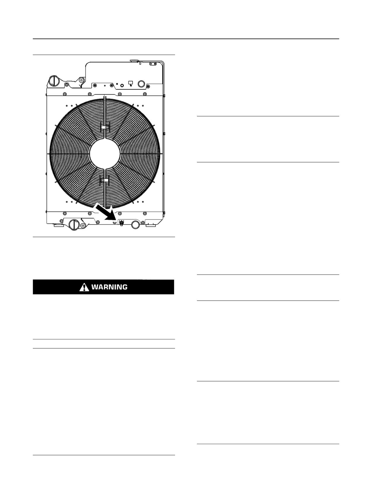
SEBU8598
65
Maintenance Recommendations
Coolant (DEAC) - Change
1. Stop the engine and allow the engine to cool.
Loosen the cooling system filler cap slowly in order
to relieve any pressure. Remove the cooling
system filler cap.
2. Open the cooling system drain valve.
Allow the coolant to drain.
NOTICE
Dispose of used engine coolant properly or recycle.
Various methods have been proposed to reclaim used
coolant for reuse in engine cooling systems. The full
distillation procedure is the only method acceptable
by Caterpillar to reclaim the used coolant.
For information regarding the disposal and the
recycling of used coolant, consult your Cat dealer or
consult Cat Dealer Service Tools Group :
Outside Illinois 1-800-542-TOOL
Inside Illinois 1-800-541-TOOL
Canada 1-800-523-TOOL
International 1-309-578-7372
Flush
Illustration 48
g02351659
1. Flush the cooling system with clean water in order
The cooling system drain valve is towards the bottom
to remove any debris.
of the radiator.
2. Close the drain valve.
Drain
NOTICE
Fill the cooling system no faster than 19 L (5 US gal)
per minute to avoid air locks.
Pressurized System: Hot coolant can cause seri-
ous burns. To open the cooling system filler cap,
3. Fill the cooling system with a mixture of clean water
stop the engine and wait until the cooling system
and Cat Fast Acting Cooling System Cleaner. Add
components are cool. Loosen the cooling system
pressure cap slowly in order to relieve the
0.5 L (1 pt) of cleaner per 15 L (4 US gal) of the
pressure.
cooling system capacity. Install the cooling system
filler cap.
NOTICE
4. Start and run the engine at low idle for a minimum
Care must be taken to ensure that fluids are con-
of 30 minutes. The coolant temperature should be
tained during performance of inspection, mainte-
at least 82 °C (180 °F).
nance, testing, adjusting and repair of the product. Be
prepared to collect the fluid with suitable containers
before opening any compartment or disassembling
NOTICE
any component containing fluids.
Improper or incomplete rinsing of the cooling system
can result in damage to copper and other metal
Refer to Special Publication, NENG2500, “Caterpillar
components.
Dealer Service Tool Catalog” or refer to Special Publi-
cation, PECJ0003, “Caterpillar Shop Supplies and
To avoid damage to the cooling system, make sure to
Tools Catalog” for tools and supplies suitable to col-
completely flush the cooling system with clear water.
lect and contain fluids on Caterpillar products.
Continue to flush the system until all signs of the
cleaning agent are gone.
Dispose of all fluids according to local regulations and
mandates.
66
SEBU8598
Maintenance Recommendations
Coolant (ELC) - Change
5. Stop the engine and allow the engine to cool.
NOTICE
Loosen the cooling system filler cap slowly in order
Fill the cooling system no faster than 19 L (5 US gal)
to relieve any pressure. Remove the cooling
per minute to avoid air locks.
system filler cap. Open the drain valve. Allow the
water to drain. Flush the cooling system with clean
1. Fill the cooling system with coolant/antifreeze.
water. If equipped, be sure to flush the heater and
Refer to this Operation and Maintenance Manual,
any related supply and return lines. Close the drain
“Fluid Recommendations” topic for more
valve.
information on cooling system specifications. Do
Cooling Systems with Heavy
not install the cooling system filler cap.
Deposits or Plugging
2. Start and run the engine at low idle. Increase the
engine rpm to 1500 rpm. Run the engine at high
Note: For the following procedure to be effective,
idle for 1 minute in order to purge the air from the
there must be some active flow through the cooling
system components.
cavities of the engine block. Stop the engine.
1. Flush the cooling system with clean water in order
3. Check the coolant level. Maintain the coolant level
to remove any debris.
within 13 mm (0.5 inch) below the bottom of the
pipe for filling. Maintain the coolant level within
2. Close the drain valve.
13 mm (0.5 inch) to the proper level on the sight
glass.
NOTICE
4. Clean the cooling system filler cap. Inspect the
Fill the cooling system no faster than 19 L (5 US gal)
gasket that is on the cooling system filler cap. If the
per minute to avoid air locks.
gasket that is on the cooling system filler cap is
damaged, discard the old filler cap and install a
3. Fill the cooling system with a mixture of clean water
new filler cap. If the gasket that is on the cooling
and Cat Fast Acting Cooling System Cleaner. Add
system filler cap is not damaged, perform a
0.5 L (1 pt) of cleaner per 3.8 to 7.6 L
pressure test. A 9S-8140 Pressurizing Pump is
(1 to 2 US gal) of the cooling system capacity.
used to perform the pressure test. The correct
Install the cooling system filler cap.
pressure for the cooling system filler cap is
stamped on the face of the cooling system filler
4. Start and run the engine at low idle for a minimum
cap. If the cooling system filler cap does not retain
of 90 minutes. The coolant temperature should be
the correct pressure, install a new cooling system
at least 82 °C (180 °F).
filler cap.
5. Start the engine. Inspect the cooling system for
NOTICE
leaks and for proper operating temperature.
Improper or incomplete rinsing of the cooling system
can result in damage to copper and other metal
components.
i04156979
To avoid damage to the cooling system, make sure to
Coolant (ELC) - Change
completely flush the cooling system with clear water.
Continue to flush the system until all signs of the
SMCS Code: 1350-070; 1395-044
cleaning agent are gone.
Clean the cooling system and flush the cooling
system before the recommended maintenance
5. Stop the engine and allow the engine to cool.
interval if the following conditions exist:
Loosen the cooling system filler cap slowly in order
• The engine overheats frequently.
to relieve any pressure. Remove the cooling
system filler cap. Open the drain valve. Allow the
• Foaming is observed.
water to drain. Flush the cooling system with clean
water.
• The oil has entered the cooling system and the
coolant is contaminated.
Fill
• The fuel has entered the cooling system and the
coolant is contaminated.
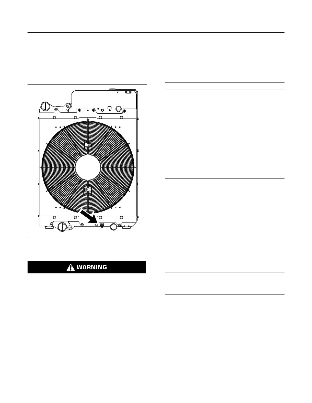
SEBU8598
67
Maintenance Recommendations
Coolant (ELC) - Change
Note: When the cooling system is cleaned, only
NOTICE
clean water is needed when the ELC is drained and
Dispose of used engine coolant properly or recycle.
replaced.
Various methods have been proposed to reclaim used
coolant for reuse in engine cooling systems. The full
Note: Inspect the water pump and the water
distillation procedure is the only method acceptable
temperature regulator after the cooling system has
by Caterpillar to reclaim the used coolant.
been drained.
NOTICE
Care must be taken to ensure that fluids are con-
tained during performance of inspection, mainte-
nance, testing, adjusting and repair of the product. Be
prepared to collect the fluid with suitable containers
before opening any compartment or disassembling
any component containing fluids.
Refer to Special Publication, NENG2500, “Caterpillar
Dealer Service Tool Catalog” or refer to Special Publi-
cation, PECJ0003, “Caterpillar Shop Supplies and
Tools Catalog” for tools and supplies suitable to col-
lect and contain fluids on Caterpillar products.
Dispose of all fluids according to local regulations and
mandates.
For information regarding the disposal and the
recycling of used coolant, consult your Cat dealer or
consult Cat Dealer Service Tool Group :
OutsideIllinois 1-800-542-TOOL
InsideIllinois 1-800-541-TOOL
Canada 1-800-523-TOOL
International 1-309-578-7372
Flush
Illustration 49
g02351659
1. Flush the cooling system with clean water in order
to remove any debris.
Drain
2. Close the drain valve.
Pressurized System: Hot coolant can cause seri-
NOTICE
ous burns. To open the cooling system filler cap,
Fill the cooling system no faster than 19 L (5 US gal)
stop the engine and wait until the cooling system
per minute to avoid air locks.
components are cool. Loosen the cooling system
pressure cap slowly in order to relieve the
3. Fill the cooling system with clean water. Install the
pressure.
cooling system filler cap.
1. Stop the engine and allow the engine to cool.
4. Start and run the engine at low idle until the
Loosen the cooling system filler cap slowly in order
temperature reaches49 to 66 °C (120 to 150 °F).
to relieve any pressure. Remove the cooling
5. Stop the engine and allow the engine to cool.
system filler cap.
Loosen the cooling system filler cap slowly in order
2. Open the cooling system drain valve.
to relieve any pressure. Remove the cooling
system filler cap. Open the drain valve. Allow the
Allow the coolant to drain.
water to drain. Flush the cooling system with clean
water. Close the drain valve.
Fill
68
SEBU8598
Maintenance Recommendations
Coolant Extender (ELC) - Add
NOTICE
Fill the cooling system no faster than 19 L (5 US gal)
per minute to avoid air locks.
Personal injury can result from hot coolant, steam
and alkali.
1. Fill the cooling system with Extended Life Coolant
At operating temperature, engine coolant is hot
and under pressure. The radiator and all lines to
(ELC). Refer to this Operation and Maintenance
heaters or the engine contain hot coolant or
Manual, “Fluid Recommendations” for more
steam. Any contact can cause severe burns.
information on cooling system specifications. Do
not install the cooling system filler cap.
Remove cooling system pressure cap slowly to
relieve pressure only when engine is stopped and
2. Start and run the engine at low idle. Increase the
cooling system pressure cap is cool enough to
touch with your bare hand.
engine rpm to high idle. Run the engine at high idle
for 1 minute in order to purge the air from the
Do not attempt to tighten hose connections when
cavities of the engine block. Stop the engine.
the coolant is hot, the hose can come off causing
burns.
3. Check the coolant level. Maintain the coolant level
within 13 mm (0.5 inch) below the bottom of the
Cooling System Coolant Additive contains alkali.
Avoid contact with skin and eyes.
pipe for filling. Maintain the coolant level within
13 mm (0.5 inch) to the proper level on the sight
glass.
NOTICE
Care must be taken to ensure that fluids are con-
4. Clean the cooling system filler cap. Inspect the
tained during performance of inspection, mainte-
gasket that is on the cooling system filler cap. Only
nance, testing, adjusting, and repair of the product.
install the used filler cap if the gasket is not
Be prepared to collect the fluid with suitable contain-
damaged. Use a 9S-8140 Pressurizing Pump to
ers before opening any compartment or disassem-
pressure test a reinstalled cooling system filler cap.
bling any component containing fluids.
The correct pressure for the cooling system filler
cap is stamped on the face of the cooling system
Refer to Special Publication, NENG2500, “Cat Dealer
Service Tool Catalog” or refer to Special Publication,
filler cap. If the cooling system filler cap does not
PECJ0003, “Cat Shop Supplies and Tools Catalog”
retain the correct pressure, install a new cooling
for tools and supplies suitable to collect and contain
system filler cap.
fluids on Cat products.
5. Start the engine. Inspect the cooling system for
Dispose of all fluids according to local regulations and
leaks and for proper operating temperature.
mandates.
i04745732
1. Loosen the cooling system filler cap slowly in order
to relieve pressure. Remove the cooling system
Coolant Extender (ELC) - Add
filler cap.
SMCS Code: 1352-544-NL
2. If necessary, drain enough coolant from the cooling
Cat ELC (Extended Life Coolant) does not require
system in order to add the Cat ELC Extender .
the frequent additions of any supplemental cooling
additives which are associated with the present
3. Add Cat ELC Extender according to the
conventional coolants. The Cat ELC Extender will
requirements for the cooling system capacity.
only be added one time.
Refer to this Operation and Maintenance Manual,
“Refill Capacities” or to this Operation and
NOTICE
Maintenance Manual, “Fluid Recommendations”
Use only Cat Extended Life Coolant (ELC) Extender
for more information.
with Cat ELC.
Do NOT use conventional supplemental coolant addi-
4. Clean the cooling system filler cap. Inspect the
tive (SCA) with Cat ELC. Mixing Cat ELC with con-
gaskets on the cooling system filler cap. Replace
ventional coolants and/or conventional SCA reduces
the cooling system filler cap if the gaskets are
the Cat ELC service life.
damaged. Install the cooling system filler cap.
Check the cooling system only when the engine is
stopped and cool.
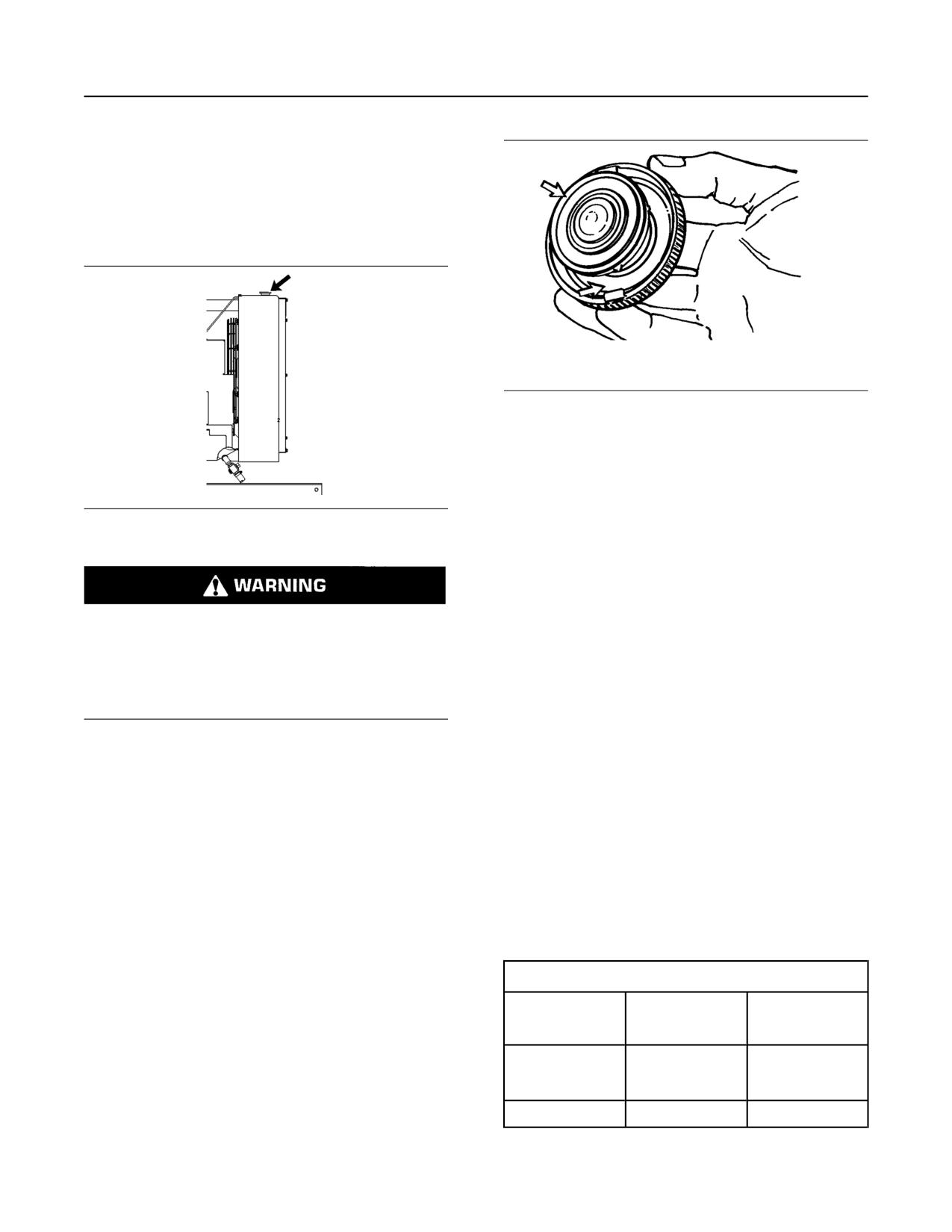
SEBU8598
69
Maintenance Recommendations
Coolant Level - Check
i03842450
Coolant Level - Check
SMCS Code: 1395-082
Check the coolant level when the engine is stopped
and cool.
Illustration 51
g00103639
Typical filler cap gaskets
3. Clean the cooling system filler cap and check the
condition of the filler cap gaskets. Replace the
cooling system filler cap if the filler cap gaskets are
damaged. Reinstall the cooling system filler cap.
Illustration 50
g00285520
Cooling system filler cap
4. Inspect the cooling system for leaks.
i04134625
Pressurized System: Hot coolant can cause seri-
Coolant Sample (Level 1) -
ous burns. To open the cooling system filler cap,
Obtain
stop the engine and wait until the cooling system
components are cool. Loosen the cooling system
SMCS Code: 1350-008; 1395-008; 1395-554; 7542
pressure cap slowly in order to relieve the
pressure.
Note: Obtaining a Coolant Sample (Level 1) is
optional if the cooling system is filled with Cat
ELC (Extended Life Coolant).
1. Remove the cooling system filler cap slowly in
order to relieve pressure.
Note: Obtain a Coolant Sample (Level 1) if the
cooling system is filled with any other coolant
2. Maintain the coolant level within 13 mm (0.5 inch)
instead of Cat ELC including the following:
of the bottom of the filler pipe. If the engine is
equipped with a sight glass, maintain the coolant
• Commercial long life coolants that meet the
Caterpillar Engine Coolant Specification -1
level to the proper level in the sight glass.
(Caterpillar EC-1)
• Cat DEAC (Diesel Engine Antifreeze/Coolant)
• Commercial heavy-duty coolant/antifreeze
Table 10
Recommended Interval
Type of
Level 1
Level 2
Coolant
Cat DEAC or any
coolant other than
Every 500 Hours(1)
Yearly(2)
Cat ELC
Cat ELC
Optional
Yearly(2)
(continued)
70
SEBU8598
Maintenance Recommendations
Coolant Sample (Level 2) - Obtain
(Table 10, contd)
i05378320
(1) This interval is the recommended interval for coolant samples
for all conventional heavy-duty coolant/antifreeze. This interval
Coolant Sample (Level 2) -
is also the recommended interval for coolant samples of com-
mercial coolants that meet the Cat EC-1 specification for engine
Obtain
coolant.
(2) The Level 2 Coolant Analysis should be performed sooner if a
SMCS Code: 1350-008; 1395-008; 1395-554; 7542
problem is suspected or identified.
NOTICE
NOTICE
Always use a designated pump for oil sampling, and
Always use a designated pump for oil sampling, and
use a separate designated pump for coolant sam-
use a separate designated pump for coolant sam-
pling. Using the same pump for both types of samples
pling. Using the same pump for both types of samples
may contaminate the samples that are being drawn.
may contaminate the samples that are being drawn.
This contaminate may cause a false analysis and an
This contaminate may cause a false analysis and an
incorrect interpretation that could lead to concerns by
incorrect interpretation that could lead to concerns by
both dealers and customers.
both dealers and customers.
NOTICE
Note: Level 1 results may indicate a need for
Care must be taken to ensure that fluids are con-
Level 2 Analysis.
tained during performance of inspection, mainte-
nance, testing, adjusting, and repair of the product.
Obtain the sample of the coolant as close as possible
to the recommended sampling interval. In order to
Be prepared to collect the fluid with suitable contain-
receive the full effect of S·O·S analysis, establish a
ers before opening any compartment or disassem-
consistent trend of data. In order to establish a
bling any component containing fluids.
pertinent history of data, perform consistent
samplings that are evenly spaced. Supplies for
Refer to Special Publication, NENG2500, “Cat Dealer
collecting samples can be obtained from your Cat
Service Tool Catalog” or refer to Special Publication,
dealer.
PECJ0003, “Cat Shop Supplies and Tools Catalog”
for tools and supplies suitable to collect and contain
Use the following guidelines for proper sampling of
fluids on Cat products.
the coolant:
Dispose of all fluids according to local regulations and
• Complete the information on the label for the
mandates.
sampling bottle before you begin to take the
samples.
Refer to Operation and Maintenance Manual,
• Keep the unused sampling bottles stored in plastic
“Cooling System Coolant Sample (Level 1) - Obtain”
for the guidelines for a proper sampling of the coolant.
bags.
Submit the sample for Level 2 analysis.
• Obtain coolant samples directly from the coolant
sample port. You should not obtain the samples
For additional information about coolant analysis, see
from any other location.
Special Publication, SEBU7003, “Cat 3600 Series
and C280 Series Diesel Engine Fluids
• Keep the lids on empty sampling bottles until you
Recommendations” or consult your Cat dealer.
are ready to collect the sample.
• Place the sample in the mailing tube immediately
i04269112
after obtaining the sample in order to avoid
contamination.
Cooling System Supplemental
Coolant Additive (SCA) - Test/
• Never collect samples from expansion bottles.
Add
• Never collect samples from the drain for a system.
(Systems Which are Filled with
Submit the sample for Level 1 analysis.
Conventional Coolant)
For additional information about coolant analysis, see
SMCS Code: 1352-045; 1395-081
this Operation and Maintenance Manual, “Fluid
Recommendations” or consult your Cat dealer.
This maintenance procedure is required for
conventional coolants such as DEAC.Do not
perform this maintenance for cooling systems
that are filled with Cat Extended Life Coolant (Cat
ELC) or Cat Extended Life Inhibitor (Cat ELI).
SEBU8598
71
Maintenance Recommendations
Diesel Particulate Filter - Clean/Replace
Note: Caterpillar recommends that an S·O·S Coolant
Analysis (Level 1) be performed to check the
concentration of SCA.
Cooling system coolant additive contains alkali.
To help prevent personal injury, avoid contact
Maintain the Proper Concentration
with the skin and eyes. Do not drink cooling sys-
tem coolant additive.
of SCA in the Coolant
NOTICE
Excessive supplemental coolant additive concentra-
tion can form deposits on the higher temperature sur-
Pressurized System: Hot coolant can cause seri-
faces of the cooling system, reducing the engine's
ous burns. To open the cooling system filler cap,
heat transfer characteristics. Reduced heat transfer
stop the engine and wait until the cooling system
could cause cracking of the cylinder head and other
components are cool. Loosen the cooling system
high temperature components.
pressure cap slowly in order to relieve the
pressure.
Excessive supplemental coolant additive concentra-
tion could also result in blockage of the heat exchang-
1. Remove the cooling system filler cap slowly.
er, overheating, and/or accelerated wear of the water
pump seal.
2. Test the concentration of the SCA with a
286-2578 Nitrite Test Strip or review the results
Do not exceed the recommended amount of supple-
mental coolant additive concentration.
of the S·O·S Coolant Analysis (Level 1).
3. If necessary, drain some coolant in order to allow
NOTICE
space for the addition of the SCA.
Do NOT mix brands or types of SCA. Do NOT mix
4. Add the amount of SCA required to maintain a
SCAs and extenders.
concentration of 3 percent to 6 percent SCA in the
Failure to follow the recommendations can result in
coolant.
shortened cooling system component life.
5. Clean the cooling system filler cap. Install the
cooling system filler cap.
NOTICE
Use Only Approved SCAs. Conventional coolants
For further information, refer to Special Publication,
require the maintenance addition of SCA throughout
SEBU6251, “Cat Commercial Diesel Engine Fluids
Recommendations”.
their expected life. Do NOT use an SCA with a cool-
ant unless specifically approved by the coolant suppli-
er for use with their coolant. It is the responsibility of
i04880440
the coolant manufacturer to ensure compatibility and
acceptable performance.
Diesel Particulate Filter - Clean/
Failure to follow the recommendations can result in
Replace
shortened cooling system component life.
(If Equipped)
SMCS Code: 108F-070; 108F-510; 1091-070; 1091-
NOTICE
510
Care must be taken to ensure that fluids are con-
tained during performance of inspection, mainte-
Consult your Cat dealer when the DPF needs to be
cleaned.
nance, testing, adjusting, and repair of the product.
Be prepared to collect the fluid with suitable contain-
The approved Caterpillar DPF maintenance
ers before opening any compartment or disassem-
procedure requires that one of the following actions
bling any component containing fluids.
be taken when the DPF needs to be cleaned:
Refer to Special Publication, NENG2500, “Cat Dealer
Service Tool Catalog” and to Special Publication,
GECJ0003, “Cat Shop Supplies and Tools” for tools
and supplies suitable to collect and contain fluids on
Cat products.
Dispose of all fluids according to applicable regula-
tions and mandates.
72
SEBU8598
Maintenance Recommendations
Driven Equipment - Check
• The DPF from your engine can be replaced with a
Inspect the Rear Gear Train
new DPF
Inspect the crankshaft gear. If excessive wear is
• The DPF from your engine can be replaced with a
found, replace the crankshaft gear and the large
remanufactured DPF
cluster idler.
If any gear causes damage to other gears through
• The DPF from your engine can be cleaned by your
failure, replace the entire rear gear train.
local authorized Cat dealer, or a Caterpillar
approved DPF cleaning machine, and reinstalled
For the correct parts, see the Parts Manual for the
engine. For removal and replacement instructions,
Note: In order to maintain emissions documentation,
see the Service Manual, “Disassembly and
the DPF that is removed from the engine when the
Assembly” module. Consult your Caterpillar dealer for
DPF is cleaned must be reinstalled on the same
assistance.
engine.
i04230004
Note: A specific ash service regeneration must be
performed before removing a DPF that will be
cleaned. All three scenarios listed above require a
Electronic Unit Injector -
reset of the ash monitoring system in the engine
Check/Replace
ECM.
SMCS Code: 1251-510; 1251-535; 1290-510; 1290-
535
i00934883
Driven Equipment - Check
SMCS Code: 3279-535
Be sure the engine cannot be started while this
maintenance is being performed. To prevent pos-
Check the Alignment
sible injury, do not use the starting motor to turn
the flywheel.
To minimize bearing problems and vibration of the
engine crankshaft and the driven equipment, the
Hot engine components can cause burns. Allow
alignment between the engine and driven equipment
additional time for the engine to cool before meas-
must be properly maintained.
uring/adjusting the unit injectors.
Check the alignment according to the instructions that
The electronic unit injectors use high voltage. Dis-
are provided by the following manufacturers:
connect the unit injector enable circuit connector
in order to prevent personal injury. Do not come
• Caterpillar
in contact with the injector terminals while the en-
gine is running.
• OEM of the drive coupling
• OEM of the driven equipment
The operation of a Cat Engine with an electronic unit
injector which is improperly adjusted may reduce
Torque all of the fasteners to the proper
engine efficiency. This reduced efficiency may result
specifications.
in excessive fuel usage and/or shortened engine
component life.
Inspect the Drive Coupling
Note: Only qualified service personnel should
Inspect the drive coupling according to the
perform this maintenance.
instructions that are provided by the OEM of the
coupling. For the following service information, see
Refer to the Systems Operation, Testing and
the literature that is provided by the OEM of the
Adjusting, “Electronic Unit Injector - Test” for the test
coupling:
procedure. Refer to Systems Operation, Testing and
Adjusting, “Electronic Unit Injector - Adjust” for the
• Lubrication requirements
adjustment procedure.
• Specifications for the end play
Refer to the Disassembly and Assembly Manual for
the procedure for the removal and replacement of the
• “Reusability Guidelines”
injector.
• Replacement instructions
SEBU8598
73
Maintenance Recommendations
Engine - Clean
i04134990
NOTICE
The camshafts must be correctly timed with the crank-
Engine Air Cleaner Element
shaft before an adjustment of the lash for the fuel in-
jector is made. The timing pins must be removed from
(Dual Element/Box Type) -
the camshafts before the crankshaft is turned or dam-
Replace
age to the cylinder block will be the result.
SMCS Code: 1054-510
i01646701
Primary Filter
Engine - Clean
NOTICE
Service the primary filter element only when the alert
SMCS Code: 1000-070
indicator for the intake air filter is flashing. Do not
open the filter compartment unless it is time for serv-
ice. Opening the filter compartment can cause dirt to
get into the clean side of the filter housing.
Personal injury or death can result from high
voltage.
NOTICE
Moisture
can
create
paths
of
electrical
conductivity.
Extremely short air filter life can result if the pre-
cleaner system malfunctions. If air filter life is drasti-
Make sure that the electrical system is OFF. Lock
cally reduced from typical for the operating
out the starting controls and tag the controls “DO
conditions, consult your Caterpillar Dealer. The ex-
NOT OPERATE” .
haust system dust ejector for the strata tube pre-
cleaner must pull a minimum vacuum of 508 mm
(20 inch) of water.
NOTICE
Accumulated grease and oil on an engine is a fire
hazard. Keep the engine clean. Remove debris and
NOTICE
fluid spills whenever a significant quantity accumu-
Service the engine air filters with the engine stopped.
lates on the engine.
Engine damage could result.
Periodic cleaning of the engine is recommended.
Steam cleaning the engine will remove accumulated
NOTICE
Do not use the filter for longer than one year.
oil and grease. A clean engine provides the following
benefits:
• Easy detection of fluid leaks
• Maximum heat transfer characteristics
• Ease of maintenance
Note: Caution must be used in order to prevent
electrical components from being damaged by
excessive water when you clean the engine. Avoid
electrical components such as the alternator, the
starter, and the ECM.
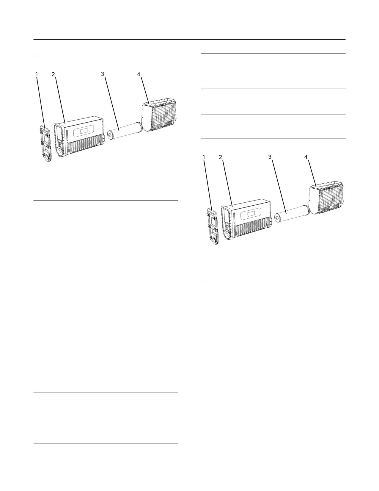
74
SEBU8598
Maintenance Recommendations
Engine Air Cleaner Element (Dual Element/Box Type) - Replace
NOTICE
The filter should be kept in service for no longer than
1 year.
NOTICE
Always leave the secondary filter element in place
while you clean the air cleaner housing.
1. Open the engine access door.
Illustration 52
g02105115
1. Remove the air cleaner cover (1). Pull out in order
to remove the element.
2. Remove the primary filter element (2) from the air
cleaner housing (4).
3. Mark the secondary filter element (3) in order to
show that the primary filter element has been
serviced. The secondary filter element should be
replaced when the primary filter element is
serviced for the third time. Refer to the section
Illustration 53
g02105115
“Secondary Filter”.
2. Remove the air cleaner housing cover (1).
4. Clean the inside of the air cleaner housing (4).
Keep the secondary filter element in place while
3. Remove the primary filter element (2). Refer to the
you clean the housing.
section “Primary Filter”.
5. Install a new primary air filter. Push the filter
4. Clean the inside of the air cleaner housing (4).
element firmly in order to properly seat the
5. Remove the secondary filter element (3). Pull out in
element. Write the date on the element, if the
order to remove the element.
primary element is replaced.
6. Install a new secondary filter element. Push the
6. Install the air cleaner cover.
element firmly in order to properly seat the
element. Write the date on the element, if the
Secondary Filter
element is replaced.
NOTICE
7. Install the primary filter element and the air cleaner
Always replace the secondary filter element. Never
housing cover.
attempt to reuse the filter by cleaning.
The secondary filter element should be replaced at
the time the primary element is serviced for the third
time.
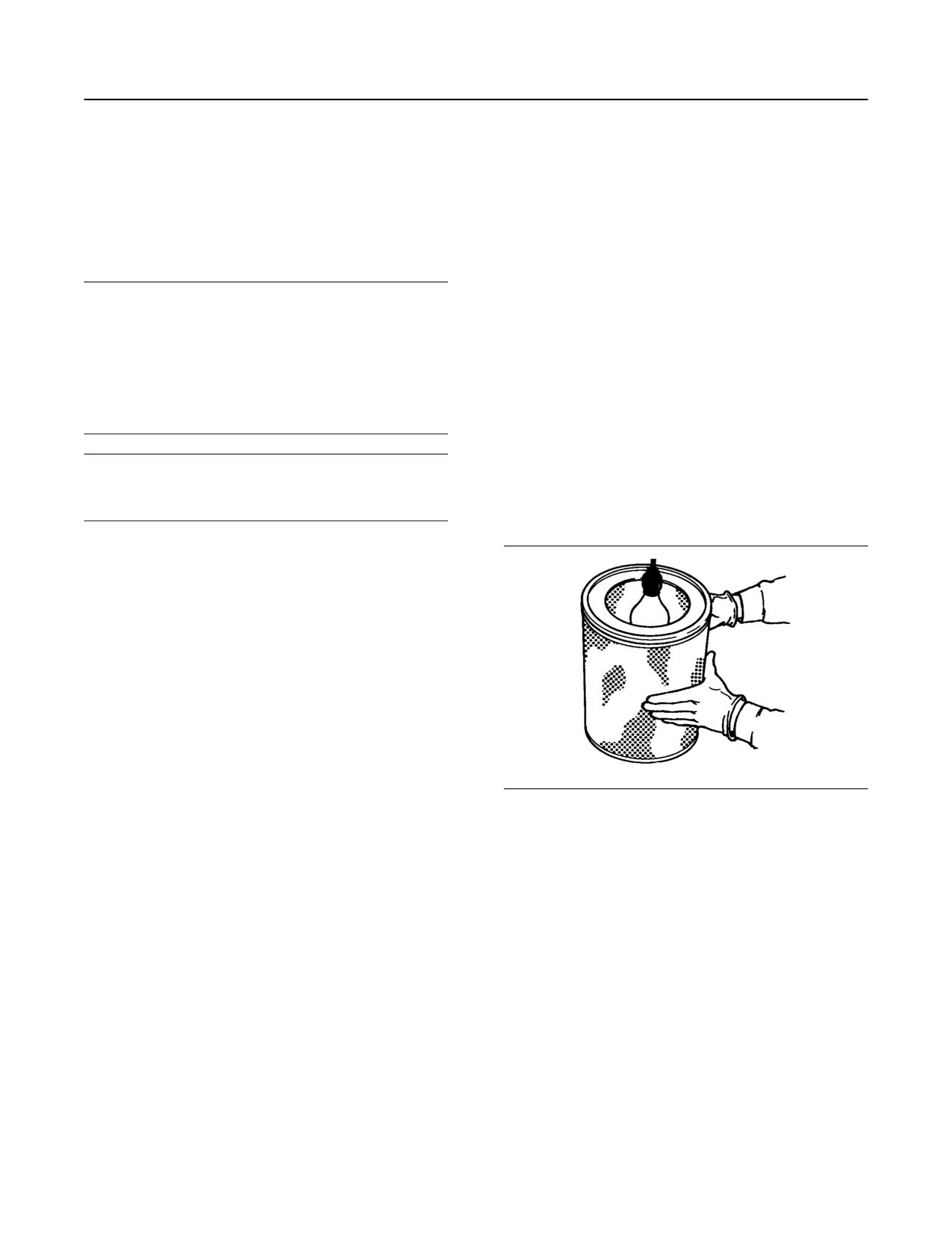
SEBU8598
75
Maintenance Recommendations
Engine Air Cleaner Element (Single Element) - Inspect/Clean/Replace
i04342930
Replace the dirty paper air cleaner elements with
clean air cleaner elements. Before installation,
thoroughly inspect the air cleaner elements for tears
Engine Air Cleaner Element
and/or holes in the filter material. Inspect the gasket
(Single Element) - Inspect/
or the seal of the air cleaner element for damage.
Maintain a supply of suitable air cleaner elements for
Clean/Replace
replacement purposes.
SMCS Code: 1051; 1054-040; 1054-070; 1054-510
1. Remove the air cleaner cover. Remove the air
cleaner element.
NOTICE
Never run the engine without an air cleaner element
2. Cover the air inlet to the turbocharger with tape in
installed. Never run the engine with a damaged air
order to keep dirt out.
cleaner element. Do not use air cleaner elements with
damaged pleats, gaskets or seals. Dirt entering the
3. Clean the inside of the air cleaner cover and body
engine causes premature wear and damage to en-
with a clean, dry cloth.
gine components. Air cleaner elements help to pre-
vent airborne debris from entering the air inlet.
4. Remove the tape for the air inlet to the
turbocharger. Install an air cleaner element that is
new or cleaned.
NOTICE
Never service the air cleaner element with the engine
5. Install the air cleaner cover.
running since this will allow dirt to enter the engine.
Inspecting Air Cleaner Elements
Note: Use of a platform may be necessary to reach
the air cleaner element.
Clean the air cleaner elements or replace the air
cleaner elements when the following conditions
occur:
• Inspect the air cleaner elements before the air filter
restriction reaches 2.5 kPa (10 inches of H2O). A
loss of engine performance may occur when the
air filter restriction exceeds this limit.
• The air cleaner elements must be cleaned or
replaced before the air filter restriction exceeds
3.75 kPa (15 inches of H2O).
Illustration 54
g00281693
Note: The air filter restriction is measured before the
air inlet to the turbocharger compressor.
Inspect the clean, dry air cleaner element. Use a 60
watt blue light in a dark room or in a similar facility.
Servicing the Air Cleaner Elements
Place the blue light in the element. Rotate the
element. Inspect the element for tears and/or holes.
Note: If the air cleaner is not manufactured by
Inspect the element for light that may show through
Caterpillar, follow the instructions that are provided by
the filter material. If it is necessary in order to confirm
the OEM of the air cleaner.
the result, compare the element to a new element that
has the same part number.
If the air cleaner element becomes plugged, the air
can split the material of the air cleaner element.
Do not use an element that has any tears and/or
Unfiltered air will drastically accelerate internal engine
holes in the filter material. Do not use an element with
wear. Your Cat dealer has the proper air cleaner
damaged pleats, gaskets or seals. Discard damaged
elements for your application. Consult your Caterpillar
elements.
dealer for the correct air cleaner element.
• Check the precleaner (if equipped) daily for
Storing Air Cleaner Elements
accumulation of dirt and debris. Remove any dirt
If an element that passes inspection will not be used,
and debris, as needed.
the element can be stored for future use.
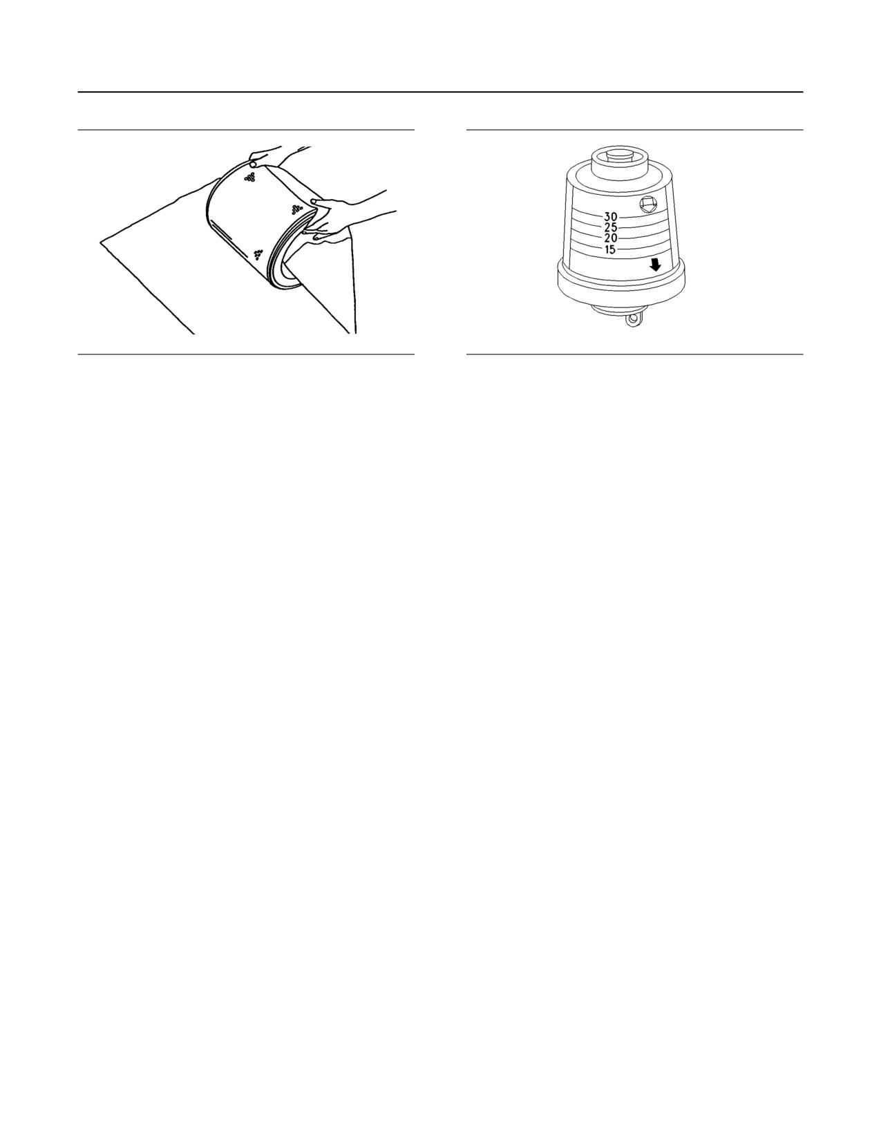
76
SEBU8598
Maintenance Recommendations
Engine Air Cleaner Service Indicator - Inspect
Illustration 55
g00281694
Illustration 56
g00103777
Typical service indicator
Do not use paint, a waterproof cover, or plastic as a
protective covering for storage. Restricted air flow
Observe the service indicator. The air cleaner
may result. To protect against dirt and damage, wrap
element should be cleaned or the air cleaner element
the elements in Volatile Corrosion Inhibited (VCI)
should be replaced when one of the following
paper.
conditions occur:
Place the element into a box for storage. For
• The yellow diaphragm enters the red zone.
identification, mark the outside of the box.
• The red piston locks in the visible position.
Store the box in a dry location.
Test the Service Indicator
i01900118
Service indicators are important instruments.
Engine Air Cleaner Service
• Check for ease of resetting. The service indicator
Indicator - Inspect
should reset in less than three pushes.
(If Equipped)
• Check the movement of the yellow core when the
SMCS Code: 7452-040
engine is accelerated to the engine rated speed.
The yellow core should latch approximately at the
Some engines may be equipped with a different
greatest vacuum that is attained.
service indicator.
If the service indicator does not reset easily, or if the
Some engines are equipped with a differential gauge
yellow core does not latch at the greatest vacuum,
for inlet air pressure. The differential gauge for inlet
the service indicator should be replaced. If the new
air pressure displays the difference in the pressure
service indicator will not reset, the hole for the service
that is measured before the air cleaner element and
indicator may be plugged.
the pressure that is measured after the air cleaner
element. As the air cleaner element becomes dirty,
The service indicator may need to be replaced
the pressure differential rises. If your engine is
frequently in environments that are severely dusty, if
equipped with a different type of service indicator,
necessary. Replace the service indicator annually
follow the OEM recommendations in order to service
regardless of the operating conditions. Replace the
the air cleaner service indicator.
service indicator when the engine is overhauled, and
whenever major engine components are replaced.
The service indicator may be mounted on the air
cleaner housing or in a remote location.
Note: When a new service indicator is installed,
excessive force may crack the top of the service
indicator. Tighten the service indicator to a torque of
2 N·m (18 lb in).
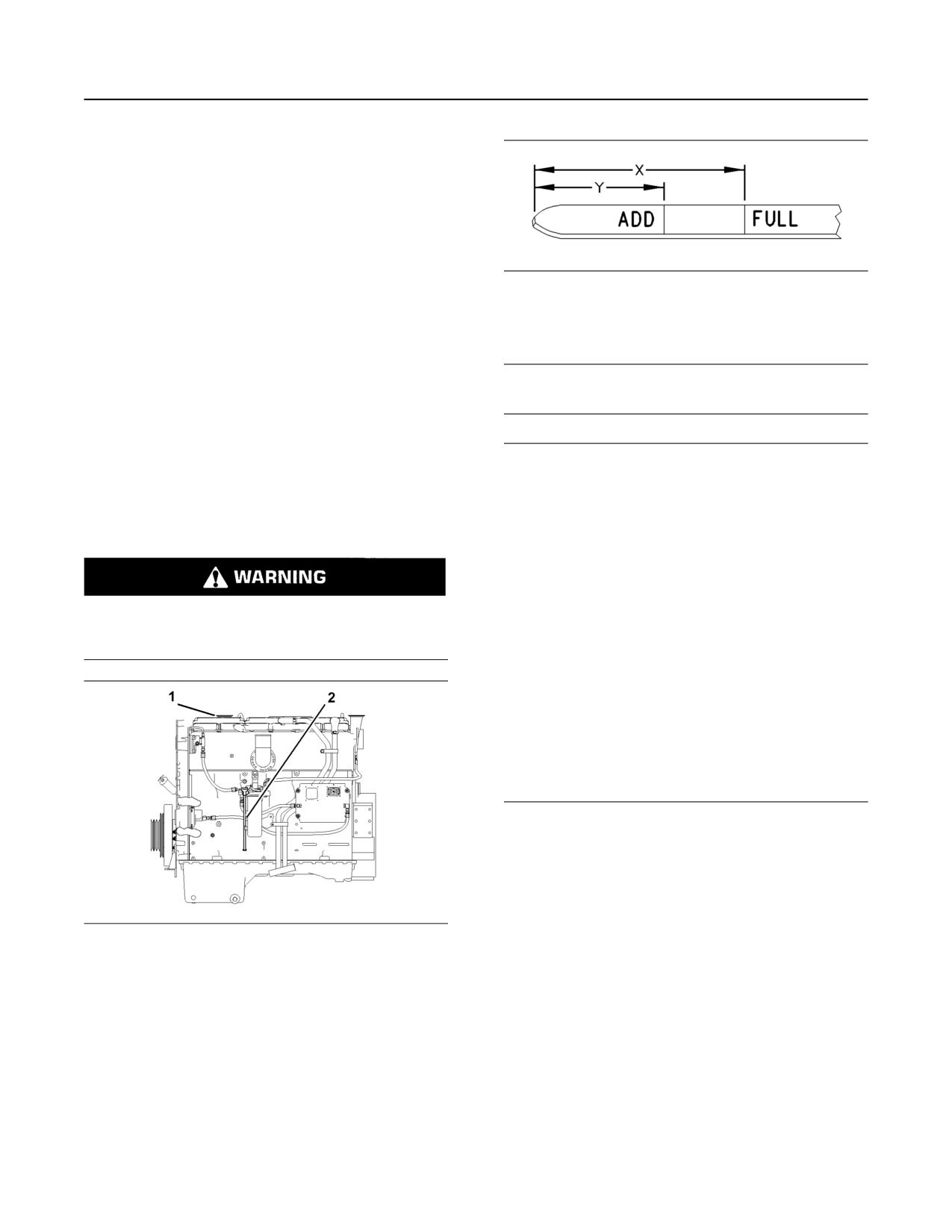
SEBU8598
77
Maintenance Recommendations
Engine Mounts - Inspect
i02436689
Engine Mounts - Inspect
SMCS Code: 1152-040; 1152
Inspect the engine mounts for deterioration and for
proper bolt torque. Engine vibration can be caused by
the following conditions:
Illustration 58
g00110310
• Improper mounting of the engine
Partial view of the oil level gauge
• Deterioration of the engine mounts
(Y) “ADD” mark
(X) “FULL” mark
• Loose mounting bolts
NOTICE
Any engine mount that shows deterioration should be
Perform this maintenance with the engine stopped.
replaced. Refer to the Specifications Manual,
SENR3130, “Torque Specifications”. Refer to your
Caterpillar dealer for more information.
NOTICE
i04137771
Engine damage can occur if the crankcase is filled
above the “FULL” mark on the oil level gauge
Engine Oil Level - Check
(dipstick).
SMCS Code: 1348-535-FLV
An overfull crankcase can cause the crankshaft to dip
into the oil. This will reduce the power that is devel-
oped and also force air bubbles into the oil. These
bubbles (foam) can cause the following problems: re-
duction of the oil's ability to lubricate, reduction of oil
Hot oil and hot components can cause personal
pressure, inadequate cooling, oil blowing out of the
injury. Do not allow hot oil or hot components to
crankcase breathers and excessive oil consumption.
contact the skin.
Excessive oil consumption will cause deposits to form
on the pistons and in the combustion chamber. De-
posits in the combustion chamber lead to the follow-
ing problems: guttering of the valves, packing of
carbon under the piston rings and wear of the cylinder
liner.
If the oil level is above the “FULL” mark on the oil lev-
el gauge, drain some of the oil immediately.
1. Remove the oil filler cap and check the oil level.
Maintain the oil level between the “ADD” mark (Y)
and the “FULL” mark (X) on the oil level gauge
(1). Do not fill the crankcase above “FULL” mark
(X).
Illustration 57
g01414582
2. In order to choose the correct type of oil for this
Typical installation of the oil level gauge
engine, refer to this Operation and Maintenance
(1) Oil filler cap
Manual, “Fluid Recommendations”.
(2) Oil level gauge
3. Clean the oil filler cap. Install the oil filler cap.
4. Record the amount of oil that is added. For the next
oil sample and analysis, include the total amount of
oil that has been added since the previous sample.
Recording this information helps to provide the
most accurate oil analysis.
78
SEBU8598
Maintenance Recommendations
Engine Oil Sample - Obtain
i04237495
NOTICE
Always use a designated pump for oil sampling, and
Engine Oil Sample - Obtain
use a separate designated pump for coolant sam-
SMCS Code: 1348-554-SM
pling. Using the same pump for both types of samples
may contaminate the samples that are being drawn.
In addition to a good preventive maintenance
This contaminate may cause a false analysis and an
program, Caterpillar recommends using S·O·S oil
incorrect interpretation that could lead to concerns by
analysis at regularly scheduled intervals. S·O·S oil
both dealers and customers.
analysis provides infrared analysis, which is required
for determining nitration and oxidation levels.
If the engine is not equipped with a sampling valve,
Obtain the Sample and the Analysis
use the 1U-5718 Vacuum Pump. The pump is
designed to accept sampling bottles. Disposable
tubing must be attached to the pump for insertion into
the sump.
Hot oil and hot components can cause personal
For instructions, see Special Publication, PEGJ0047,
injury. Do not allow hot oil or hot components to
“How To Take A Good S·O·S Oil Sample”. Consult
your Cat dealer for complete information and
contact the skin.
assistance in establishing an S·O·S program for your
engine.
Before you take the oil sample, complete the Label,
PEEP5031 for identification of the sample. In order to
i05295270
help obtain the most accurate analysis, provide the
following information:
Engine Oil and Filter - Change
• Engine model
SMCS Code: 1318-510
• Service hours on the engine
• The number of hours that have accumulated since
the last oil change
Hot oil and hot components can cause personal
injury. Do not allow hot oil or hot components to
• The amount of oil that has been added since the
contact the skin.
last oil change
To ensure that the sample is representative of the oil
Selection of Oil Change Interval
in the crankcase, obtain a warm, mixed oil sample.
To avoid contamination of the oil samples, the tools
Refer to this Operation and Maintenance Manual,
and the supplies that are used for obtaining oil
“Fluid Recommendations” for further information
about oils that may be used in Caterpillar engines.
samples must be clean.
Refer to this Operation and Maintenance Manual,
Caterpillar recommends using the sampling valve in
“Severe Service Application” to determine if the oil
order to obtain oil samples. The quality and the
change interval should be reduced from the normal
consistency of the samples are better when the
change interval. If operating in any of the conditions
sampling valve is used. The location of the sampling
or environments outlined in the Severe Service
valve allows oil that is flowing under pressure to be
Application, use S·O·S Services oil analysis to
obtained during normal engine operation.
determine the oil change interval. If S·O·S Services
oil analysis is not being used, the oil change interval
The 169-8373 Fluid Sampling Bottle is
should be reduced to 250 hrs.
recommended for use with the sampling valve. The
fluid sampling bottle includes the parts that are
Table 11
needed for obtaining oil samples. Instructions are
Oil Change Interval(1)
also provided.
Multigrade Oil Type
Operating Conditions
Normal
Severe Service
Application
(continued)
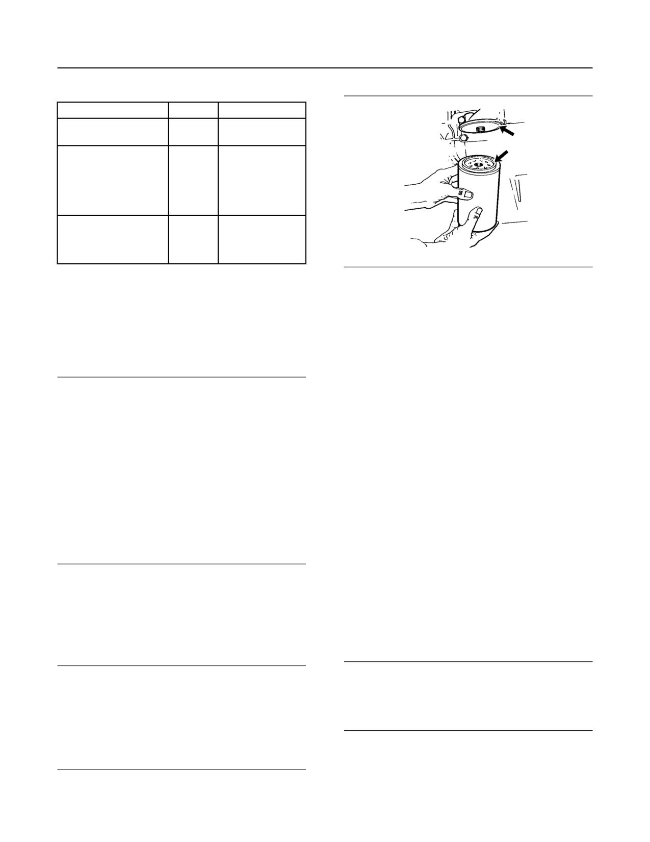
SEBU8598
79
Maintenance Recommendations
Engine Oil and Filter - Change
(Table 11, contd)
Cat DEO-ULS
500 hr
250 hr
Preferred
Oil meeting the requirements
500 hr
250 hr
of the Cat ECF-3 Specifica-
tion or the API CJ-4
classification
8 minimum TBN
Preferred
Oil meeting the requirements
500 hr
250 hr
of the ACEA C9/E6
Specification
TBN below 10.4
(1) Refer to Special Publication, PEHJ0192, “Optimizing Oil
Illustration 59
g00103713
Change Intervals” for further information..
Typical filter mounting base and filter gasket
Drain the Engine Oil
1. Remove the oil filter with a 185-3630 Strap
Wrench.
After the engine has been run at the normal operating
temperature, stop the engine. Attach a “DO NOT
2. Cut the oil filter open with a 175-7546 Oil Filter
OPERATE” or a similar warning tag to the ignition
Cutter Gp. Break apart the pleats and inspect the
keyswitch before the engine is serviced.
oil filter for metal debris. An excessive amount of
metal debris in the oil filter may indicate early wear
NOTICE
or a pending failure.
Care must be taken to ensure that fluids are con-
tained during performance of inspection, mainte-
Use a magnet to differentiate between the ferrous
nance, testing, adjusting, and repair of the product.
metals and the nonferrous metals that are found in
Be prepared to collect the fluid with suitable contain-
the oil filter element. Ferrous metals may indicate
ers before opening any compartment or disassem-
wear on the steel and cast iron parts of the engine.
bling any component containing fluids.
Nonferrous metals may indicate wear on the
Refer to Special Publication, NENG2500, “Cat Dealer
aluminum parts, brass parts, or bronze parts of the
Service Tool Catalog” or refer to Special Publication,
engine. Parts that may be affected include the
PECJ0003, “Cat Shop Supplies and Tools Catalog”
following items: main bearings, rod bearings,
for tools and supplies suitable to collect and contain
turbocharger bearings and cylinder heads.
fluids on Cat products.
Due to normal wear and friction, small amounts of
Dispose of all fluids according to local regulations and
debris may be found in the oil filter. Consult your
mandates.
Cat dealer in order to arrange for a further
analysis if an excessive amount of debris is found
in the oil filter.
1. Remove the oil drain plug in order to allow the oil to
3. Clean the sealing surface of the filter mounting
drain.
base. Ensure that all of the old oil filter gasket is
2. After the oil has drained, the oil drain plug should
removed.
be cleaned and installed.
4. Apply clean engine oil to the new oil filter gasket.
Replace the Oil Filter
NOTICE
NOTICE
Do not fill the oil filters with oil before installing them.
Caterpillar oil filters are built to Caterpillar specifica-
This oil would not be filtered and could be contami-
tions. Use of an oil filter not recommended by Cater-
nated. Contaminated oil can cause accelerated wear
pillar could result in severe engine damage to the
to engine components.
engine bearings, crankshaft, etc., as a result of the
larger waste particles from unfiltered oil entering the
engine lubricating system. Only use oil filters recom-
mended by Caterpillar .
80
SEBU8598
Maintenance Recommendations
Engine Storage Procedure - Check
5. Install the oil filter. Tighten the oil filter until the oil
• Mileage
filter gasket contacts the base. Tighten the oil filter
• Operating hours
by hand according to the instructions that are
shown on the oil filter. Do not overtighten the oil
• Fuel consumption
filter.
If an engine is out of operation and if use of the
Fill the Engine Crankcase
engine is not planned, special precautions should be
made. If the engine will be stored for more than three
months, a complete protection procedure is
1. Remove the oil filler cap. Fill the crankcase with the
recommended. For more detailed information on
proper amount of oil. Refer to the Operation and
engine storage, see Special Instruction, SEHS9031,
Maintenance Manual, “Fluid Recommendations”
“Storage Procedure For Caterpillar Products”.
topic (Maintenance Section) for more information.
If the engine will not be started for several weeks, the
lubricating oil will drain from the cylinder walls and
NOTICE
from the piston rings. Rust can form on the cylinder
If equipped with an auxiliary oil filter or system, extra
liner surface. Rust on the cylinder liner surface will
oil must be added when filling the crankcase. Follow
cause increased engine wear and a reduction in
engine service life. Caterpillar recommends the use
the OEM or filter manufacturer's recommendations. If
of volatile corrosion inhibitor (VCI) oil in order to
the extra oil is not added, the engine may starve for
prevent internal engine damage due to moisture
oil.
during storage. These inhibitors in the VCI oil act by
evaporating inside the engine. The inhibitors then
condense over the inside surfaces of the engine. The
NOTICE
evaporation process and the condensing process
To help prevent crankshaft or bearing damage, crank
offers full protection to surfaces that cannot be
engine to fill all filters before starting. Do not crank en-
reached with preservatives. 0.9 L (1.0 qt) of
gine for more than 30 seconds.
4C-6792 VCI oil will treat 28.4 L (30.0 qt) of engine
oil. This will give a 3 percent concentration of VCI oil.
The engine must be completely sealed when the
2. Start the engine and run the engine at “LOW IDLE”
engine is stored in order for the VCI oil to function
for 2 minutes. Perform this procedure in order to
properly. The VCI oil is easily cleaned from the engine
ensure that the lubrication system has oil and that
when you remove the engine from storage. The
volatile vapors are removed by simply running the
the oil filters are filled. Inspect the oil filter for oil
engine to operating temperature. A mineral oil base is
leaks.
left behind after the volatile vapors are removed.
3. Stop the engine and allow the oil to drain back to
the sump for a minimum of 10 minutes.
i03964791
4. Remove the oil level gauge in order to check the oil
Engine Valve Lash - Check
level. Maintain the oil level between the “ADD”
SMCS Code: 1105-535
and “FULL” marks on the “ENGINE STOPPED”
side of the oil level gauge.
Note: Procedures for adjusting the valve lash can be
found in Systems Operation/Testing and Adjusting,
i01458399
“Valve Lash Adjustment”. Consult your Cat dealer for
assistance.
Engine Storage Procedure -
Check
SMCS Code: 1000-535
Ensure that the engine cannot be started while
this maintenance is being performed. To help pre-
The oil change interval may be extended to 12
vent possible injury, do not use the starting motor
months for a vehicle that is operated seasonally and
to turn the flywheel.
placed in storage for the remainder of the year by
using the required storage procedures and the
Hot engine components can cause burns. Allow
required start-up procedures. This extension is
additional time for the engine to cool before meas-
permitted if the following categories for oil change
uring/adjusting valve lash clearance.
intervals in the Operation and Maintenance Manual,
“Maintenance Interval Schedule” have not been
reached:
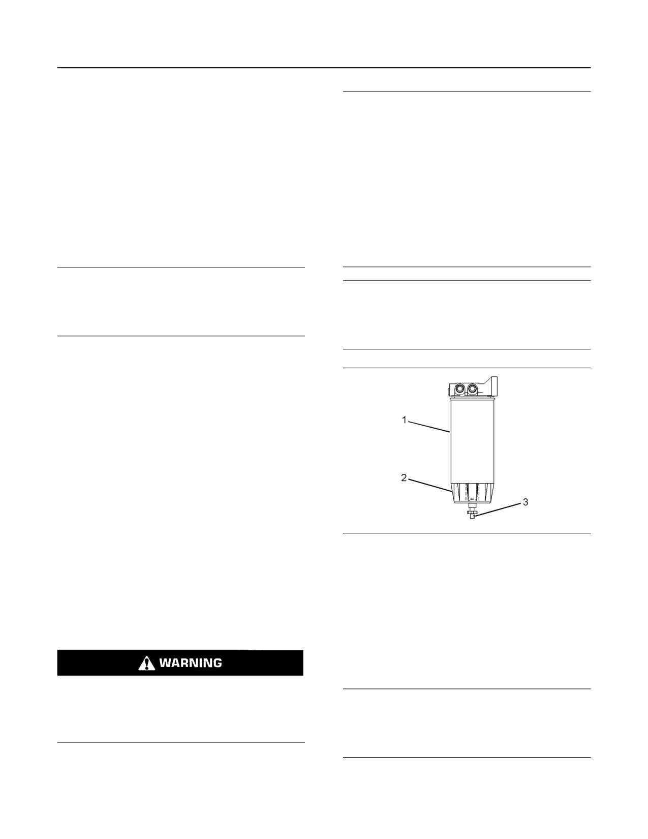
SEBU8598
81
Maintenance Recommendations
Fuel Priming Pump - Replace
i03927830
NOTICE
Care must be taken to ensure that fluids are con-
Fuel Priming Pump - Replace
tained during performance of inspection, mainte-
SMCS Code: 1258-510
nance, testing, adjusting and repair of the product. Be
prepared to collect the fluid with suitable containers
A replacement kit is available for the electronic fuel
before opening any compartment or disassembling
priming pump. Contact your Cat dealer for the correct
any component containing fluids.
part number and details for your application.
Refer to Special Publication, NENG2500, “Caterpillar
Dealer Service Tool Catalog” for tools and supplies
i02096133
suitable to collect and contain fluids on Caterpillar
products.
Fuel System - Prime
Dispose of all fluids according to local regulations and
SMCS Code: 1250-548; 1258-548
mandates.
NOTICE
Do not allow dirt to enter the fuel system. Thoroughly
NOTICE
clean the area around a fuel system component that
Do not allow dirt to enter the fuel system. Thoroughly
will be disconnected. Fit a suitable cover over discon-
clean the area around a fuel system component that
nected fuel system component.
will be disconnected. Fit a suitable cover over discon-
nected fuel system component.
1. Turn the engine start switch to the ON position.
Leave the engine start switch in the ON position for
two minutes.
2. Verify that the water separator is full of fuel.
3. If the water separator is not full of fuel, turn the
engine start switch OFF and then turn the engine
start switch ON. This will cycle the fuel priming
pump again.
4. When the water separator is full of fuel, attempt to
start the engine. If the engine starts and the engine
runs rough or the engine misfires, operate at low
idle until the engine is running smoothly. If the
engine cannot be started, or if the engine
Illustration 60
g01453091
continues to misfire or smoke, repeat Step 1.
(1) Element
(2) Bowl
i02927285
(3) Drain
Bowl (2) should be monitored daily for signs of water.
Fuel System Primary Filter/
If water is present, drain the water from the bowl.
Water Separator - Drain
1. Open drain (3). The drain is a self-ventilated drain.
SMCS Code: 1260-543; 1263-543
Catch the draining water in a suitable container.
Dispose of the water properly.
2. Close drain (3).
Fuel leaked or spilled onto hot surfaces or electri-
cal components can cause a fire. To help prevent
NOTICE
possible injury, turn the start switch off when
The water separator is under suction during normal
changing fuel filters or water separator elements.
engine operation. Ensure that the drain valve is tight-
Clean up fuel spills immediately.
ened securely to help prevent air from entering the
fuel system.
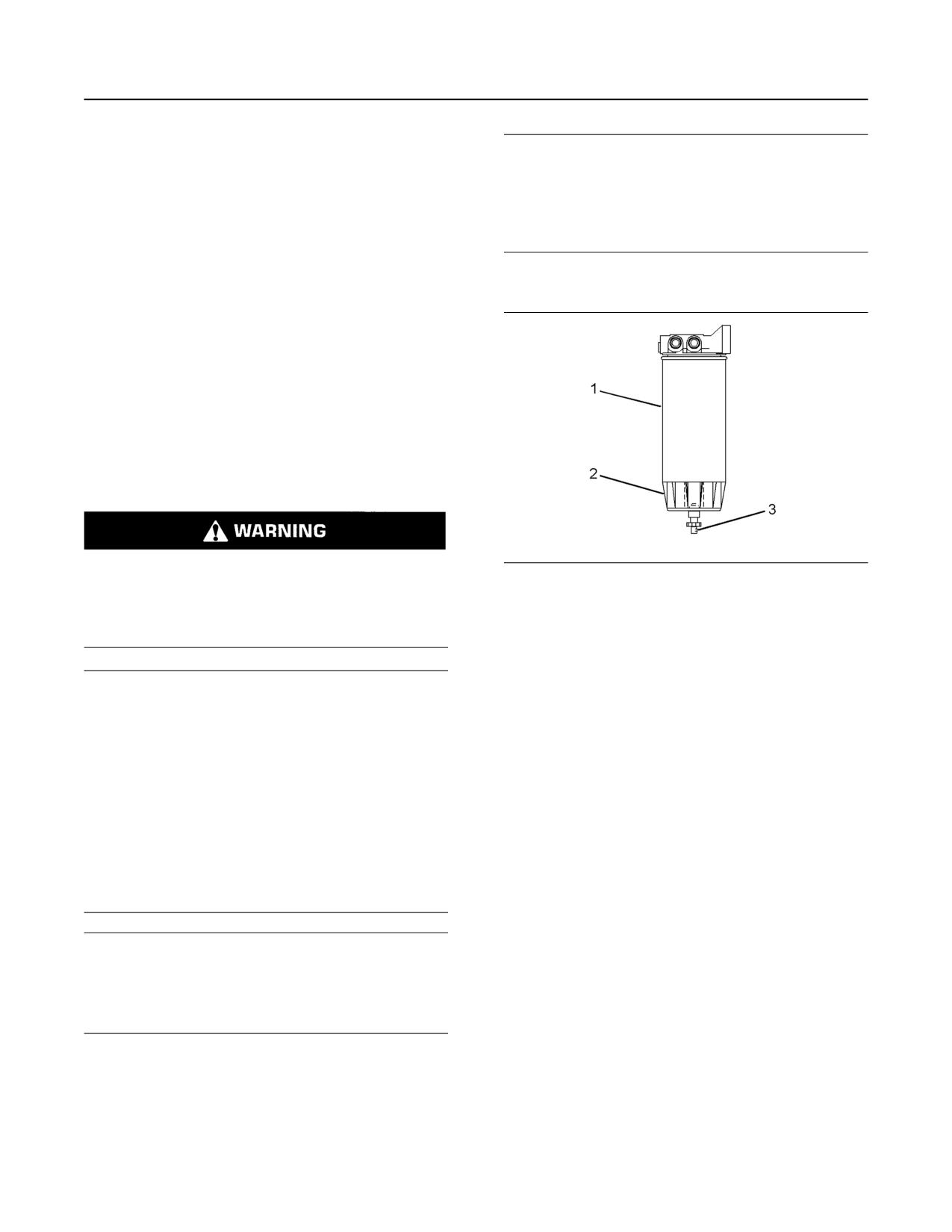
82
SEBU8598
Maintenance Recommendations
Fuel System Primary Filter (Water Separator) Element - Replace
i05354209
NOTICE
Do not fill fuel filters with fuel before installing
Fuel System Primary Filter
them. The fuel will not be filtered and could be
(Water Separator) Element -
contaminated. Contaminated fuel will cause accel-
erated wear to fuel system parts. The fuel system
Replace
should be primed prior to starting the engine.
SMCS Code: 1260-510-FQ; 1263-510-FQ
1. Close the main fuel supply valve.
Water in the fuel can cause the engine to run rough.
Water in the fuel may cause an electronic unit injector
to fail. If the fuel has been contaminated with water,
the element should be changed before the regularly
scheduled interval.
The primary filter/water separator also provides
filtration in order to help extend the life of the
secondary fuel filter. The element should be changed
regularly. If a vacuum gauge is installed, the primary
filter/water separator should be changed at
50 to 70 kPa (15 to 20 inches Hg).
Replace the Element
Fuel leaked or spilled onto hot surfaces or electri-
Illustration 61
g01453091
cal components can cause a fire. To help prevent
(1) Element
possible injury, turn the start switch off when
(2) Bowl
changing fuel filters or water separator elements.
(3) Drain
Clean up fuel spills immediately.
2. Remove element (1) from the element mounting
base while bowl (2) is attached.
NOTICE
Care must be taken to ensure that fluids are con-
3. Dispose of the contents of the filter. Remove bowl
tained during performance of inspection, mainte-
(2) from element (1). The bowl is reusable. Do not
nance, testing, adjusting, and repair of the product.
discard the bowl. Dispose of the used element.
Be prepared to collect the fluid with suitable contain-
ers before opening any compartment or disassem-
4. Remove the O-ring from the gland of the bowl.
bling any component containing fluids.
Clean the following components:
Refer to Special Publication, NENG2500, “Dealer
• Bowl
Service Tool Catalog” for tools and supplies suitable
to collect and contain fluids on Cat products.
• O-ring
Dispose of all fluids according to local regulations and
mandates.
• Mounting base
Inspect the O-ring for damage and for
deterioration. Replace the O-ring, if necessary.
NOTICE
Do not allow dirt to enter the fuel system. Thoroughly
5. Lubricate the O-ring with clean diesel fuel.
clean the area around a fuel system component that
will be disconnected. Fit a suitable cover over discon-
6. Install bowl (2) on a new element. Tighten the bowl
nected fuel system component.
by hand. Do not use tools in order to tighten the
bowl.
7. Lubricate the top seal of element (1) with clean
diesel fuel. Install the new element on the
mounting base. Tighten the element by hand.
SEBU8598
83
Maintenance Recommendations
Fuel System Secondary Filter - Replace
1. Stop the engine. Turn the ignition switch to the OFF
NOTICE
position or disconnect the battery. Refer to this
The water separator is under suction during normal
Operation and Maintenance Manual, “Battery or
engine operation. Ensure that the vent plug is tight-
Battery Cable - Disconnect” for more information.
ened securely to help prevent air from entering the
fuel system.
Shut off the fuel supply valve (if equipped).
2. It may be necessary to relieve residual fuel
8. Open the main fuel supply valve.
pressure from the fuel system before the fuel filters
are removed. Wait from 1 minute to 5 minutes until
9. Start the engine and check for leaks. Run the
the fuel pressure has lowered. Use a suitable
engine for 1 minute. Stop the engine and check for
container in order to catch any fuel that may spill.
leaks again.
3. Remove the used fuel filters and discard the used
Detecting leaks is difficult while the engine is
fuel filters.
running. The primary filter/water separator is under
suction. A leak will allow air to enter the fuel. The
4. Apply clean diesel fuel to the new fuel filter o-rings.
air in the fuel can cause low power due to aeration
of the fuel. Ensure that the components are
correctly installed to prevent air from entering the
fuel system.
NOTICE
Do not fill the secondary fuel filter with fuel before in-
stalling. The fuel would not be filtered and could be
i04158105
contaminated. Contaminated fuel will cause acceler-
ated wear to fuel system parts.
Fuel System Secondary Filter -
Replace
NOTICE
SMCS Code: 1261-510-SE
In order to meet expected fuel system component life,
4 micron(c) absolute or less secondary fuel filtration is
required for all Caterpillar Diesel Engines that are
equipped with unit injected fuel systems. Note that all
Fuel leaked or spilled onto hot surfaces or electri-
current Caterpillar
Diesel Engines are factory
cal components can cause a fire. To help prevent
equipped with Caterpillar Advanced Efficiency 4 mi-
possible injury, turn the start switch off when
cron(c) absolute fuel filters.
changing fuel filters or water separator elements.
Caterpillar does not warrant the quality or perform-
Clean up fuel spills immediately.
ance of non-Caterpillar fluids and filters.
NOTICE
5. Install the new fuel filters. Spin the fuel filters onto
Do not allow dirt to enter the fuel system. Thoroughly
the fuel filter bases until the o-rings contact the
clean the area around a fuel system component that
bases. Use the rotation index marks on the filters
will be disconnected. Fit a suitable cover over any dis-
as a guide for proper tightening. Tighten the filters
connected fuel system components.
according to the instructions that are on the fuel
filters. Do not overtighten the filters.
NOTICE
6. Open the fuel supply valve. The engine will need to
Care must be taken to ensure that fluids are con-
be purged of air. Refer to this Operation and
tained during performance of inspection, mainte-
Maintenance Manual, “Fuel System - Prime” for
nance, testing, adjusting and repair of the product. Be
more information.
prepared to collect the fluid with suitable containers
before opening any compartment or disassembling
any component containing fluids.
Refer to Special Publication, NENG2500, “Caterpillar
Dealer Service Tool Catalog” or refer to Special Publi-
cation, PECJ0003, “Caterpillar Shop Supplies and
Tools Catalog” for tools and supplies suitable to col-
lect and contain fluids on Caterpillar products.
Dispose of all fluids according to local regulations and
mandates.
84
SEBU8598
Maintenance Recommendations
Fuel Tank Water and Sediment - Drain
i06007431
Fill the fuel tank after operating the engine in order to
drive out moist air. This procedure will help prevent
condensation. Do not fill the tank to the top. The fuel
Fuel Tank Water and Sediment
expands as the fuel gets warm. The tank may
- Drain
overflow.
SMCS Code: 1273-543-M&S
Some fuel tanks use supply pipes that allow water
and sediment to settle below the end of the fuel
supply pipe. Some fuel tanks use supply lines that
NOTICE
take fuel directly from the bottom of the tank. If the
Care must be taken to ensure that fluids are con-
engine is equipped with this system, regular
tained during performance of inspection, mainte-
maintenance of the fuel system filter is important.
nance, testing, adjusting, and repair of the product.
Be prepared to collect the fluid with suitable contain-
Fuel Storage Tanks
ers before opening any compartment or disassem-
bling any component containing fluids.
Drain the water and the sediment from the fuel
storage tank during the following conditions:
Refer to Special Publication, NENG2500, “Cat Dealer
Service Tool Catalog” or refer to Special Publication,
• Weekly
PECJ0003, “Cat Shop Supplies and Tools Catalog”
for tools and supplies suitable to collect and contain
• Oil change
fluids on Cat products.
• Refill of the tank
Dispose of all fluids according to local regulations and
mandates.
This procedure will help prevent water or sediment
from being pumped from the storage tank into the
engine fuel tank. A four micron(c) absolute filter for
the breather vent on the fuel tank is also
Fuel Tank
recommended.
Fuel quality is critical to the performance and to the
If a bulk storage tank has been refilled or moved
service life of the engine. Water in the fuel can cause
recently, allow adequate time for the sediment to
excessive wear to the fuel system. Condensation
settle before filling the engine fuel tank. Internal
occurs during the heating and cooling of fuel. The
baffles in the bulk storage tank will also help trap
condensation occurs as the fuel passes through the
sediment. Filtering fuel that is pumped from the
fuel system and the fuel returns to the fuel tank. This
storage tank helps to ensure the quality of the fuel.
causes water to accumulate in fuel tanks. Draining
When possible, water separators should be used.
the fuel tank regularly and obtaining fuel from reliable
sources can help to eliminate water in the fuel.
i03735862
Drain the Water and the Sediment
Fumes Disposal Filter Element
Fuel tanks should contain some provision for draining
water and draining sediment from the bottom of the
- Replace
fuel tanks.
(Open Crankcase Ventilation
Prepare to catch water and sediment in an
(OCV) Filter)
appropriate container. Connect a hose (if necessary)
to the valve prior to opening the valve.
Open the drain valve on the bottom of the fuel tank in
order to drain the water and the sediment. Close the
drain valve.
Note: Failure to close the drain can allow air into the
system, which could have detrimental results to
performance.
Check the fuel daily. Drain the water and sediment
from the fuel tank after operating the engine. Drain
the water and sediment from the fuel tank after the
fuel tank has been filled. Allow 5 to 10 minutes before
performing this procedure.
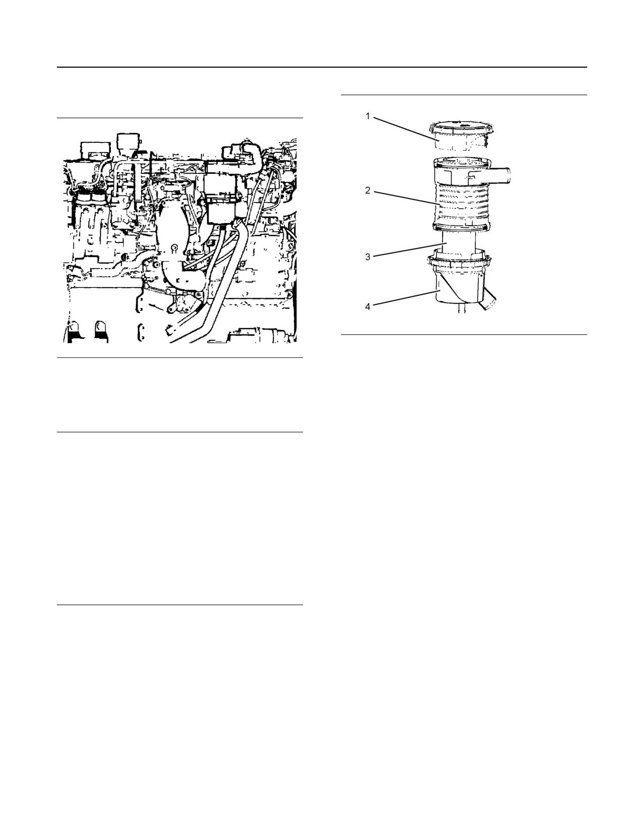
SEBU8598
85
Maintenance Recommendations
Fumes Disposal Filter Element - Replace
SMCS Code: 1074
Illustration 63
g02021434
(1) Cap
Illustration 62
g02021473
(2) Housing for the filter element
(3) Filter element
The filter for the open crankcase ventilation system
(4) Cup
may be located toward the front or toward the rear of
the left side of the engine. A filter that has been used
Remove either the cap or the cup from the housing
may contain a small amount of engine oil.
for the OCV filter. Remove the OCV filter. The filter
may not be used again. Dispose of the filter. Place a
new OCV filter inside the filter housing. If the cap was
NOTICE
removed, replace the cap. If the cup was removed,
Care must be taken to ensure that fluids are con-
replace the cup. Tighten hand tight.
tained during performance of inspection, mainte-
nance, testing, adjusting and repair of the machine.
Note: Caterpillar will not be held liable for an engine
Be prepared to collect the fluid with suitable contain-
that does not comply with EPA emissions standards
ers before opening any compartment or disassem-
due to modification of the OCV filter or due to the use
bling any component containing fluids.
of a filter that is not approved by Caterpillar.
Refer to Special Publication, NENG2500, “Caterpillar
Tools and Shop Products Guide”, for tools and sup-
plies suitable to collect and contain fluids in Caterpil-
lar machines.
Dispose of all fluids according to local regulations and
mandates.
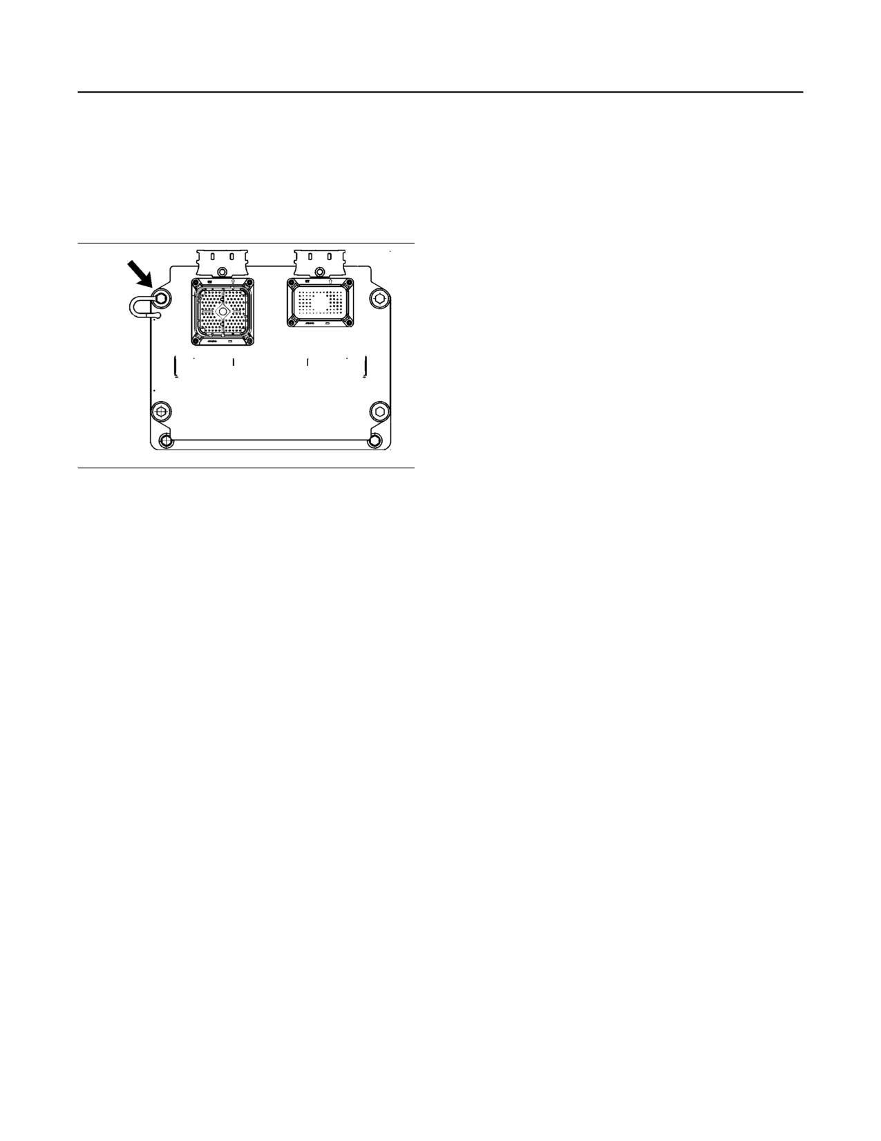
86
SEBU8598
Maintenance Recommendations
Grounding Stud - Inspect/Clean/Tighten
i03965989
Note: Always use a board or cardboard when the
engine components are checked for leaks. Leaking
Grounding Stud - Inspect/
fluid that is under pressure can cause serious injury
or possible death. Leaks that are the size of a pin
Clean/Tighten
hole are included. Refer to Operation and
SMCS Code: 7423-040; 7423-070; 7423-079
Maintenance Manual, “General Hazard Information”
for more information.
Inspect the Hoses and the Clamps
Inspect all hoses for leaks that are caused by the
following conditions. Replace any hose which exhibits
any of the following conditions. Failure to replace a
hose which exhibits any of the following conditions
may result in a hazardous situation.
• Hoses which are cracked
• Hoses which are soft
• Outer covering that is chafed or cut
• Exposed wire that is used for reinforcement
Illustration 64
g01376112
• Outer covering that is ballooning locally
The grounding stud is located on the upper left corner
of the engine control module.
• Flexible part of the hose that is kinked or crushed
Inspect the OEM harness for good connections.
• Armoring that is embedded in the outer covering
Inspect the condition of the OEM harness.
• Hoses which exhibit signs of leakage which are not
The grounding stud must have a wire ground to the
the result of loose couplings or clamps
battery. Tighten the grounding stud at every oil
change. Ground wires and straps should be
Inspect all clamps for the following conditions.
combined at engine grounds. All grounds should be
Replace any clamp which exhibits signs of any of the
tight and free of corrosion.
following conditions.
• Clean the grounding stud and the terminals for the
• Cracking
ground strap with a clean cloth.
• Looseness
• If the connections are corroded, clean the
connections with a solution of baking soda and
• Damage
water.
Inspect all couplings for leaks. Replace any coupling
• Keep the grounding stud and the strap clean and
which exhibits signs of leaks.
coated with MPGM grease or petroleum jelly.
Each installation application can be different. The
differences depend on the following factors:
i05909284
• Type of hose
Hoses and Clamps - Inspect/
• Type of fitting material
Replace
• Anticipated expansion and contraction of the hose
SMCS Code: 7554-040; 7554-510
• Anticipated expansion and contraction of the
Hoses and clamps must be inspected periodically
fittings
and replaced at the recommended interval to ensure
safe and continuous operation of the engine. Failure
Due to extreme temperature changes, the hose will
to replace a fuel hose at the recommended change
heat set. Heat setting causes hose clamps to loosen
interval may result in a hazardous situation. Take
which can result in leaks. A constant torque hose
proper safety precautions before inspecting or
clamp will help to prevent loose hose clamps.
replacing hoses and clamps.
SEBU8598
87
Maintenance Recommendations
Hoses and Clamps - Inspect/Replace
Replace hoses that are cracked or soft. Replace
5. Drain the coolant from the cooling system to a level
hoses that show signs of leakage. Replace hoses
that is below the hose that is being replaced. Drain
that show signs of damage. Replace hose clamps
the coolant into a suitable clean container. The
that are cracked or damaged. Tighten or replace hose
coolant can be reused.
clamps which are loose.
6. Remove the hose clamps.
Replace the Hoses and the Clamps
7. Disconnect the old hose.
NOTICE
Care must be taken to ensure that fluids are con-
8. Replace the old hose with a new hose.
tained during performance of inspection, mainte-
nance, testing, adjusting, and repair of the product.
9. Install hose clamps which have been inspected or
Be prepared to collect the fluid with suitable contain-
install new hose clamps. Refer to Specifications,
ers before opening any compartment or disassem-
SENR3130, “Torque Specifications”, “Hose
bling any component containing fluids.
Clamps” for information about selecting and
installing the proper hose clamps.
Refer to Special Publication, NENG2500, “Cat Dealer
Service Tool Catalog” or refer to Special Publication,
10. Refill the cooling system.
PECJ0003, “Cat Shop Supplies and Tools Catalog”
for tools and supplies suitable to collect and contain
11. Clean the filler cap for the cooling system. Inspect
fluids on Cat products.
the gaskets on the filler cap. Replace the filler cap
Dispose of all fluids according to local regulations and
if the gaskets are damaged. Install the filler cap.
mandates.
12. Start the engine. Inspect the cooling system for
leaks.
Cooling System
Fuel System
Pressurized System: Hot coolant can cause seri-
ous burns. To open the cooling system filler cap,
Personal injury can result from removing hoses
stop the engine and wait until the cooling system
or fittings in a pressure system.
components are cool. Loosen the cooling system
Failure to relieve pressure can cause personal
pressure cap slowly in order to relieve the
injury.
pressure.
Do not disconnect or remove hoses or fittings un-
til all pressure in the system has been relieved.
Personal injury can result from removing hoses
or fittings in a pressure system.
Contact with high pressure fuel may cause fluid
Failure to relieve pressure can cause personal
penetration and burn hazards. High pressure fuel
injury.
spray may cause a fire hazard. Failure to follow
Do not disconnect or remove hoses or fittings un-
these inspection, maintenance and service in-
til all pressure in the system has been relieved.
structions may cause personal injury or death.
1. Stop the engine.
NOTICE
Do not bend or strike high pressure lines. Do not in-
2. Allow the engine to cool.
stall bent or damaged lines, tubes or hoses. Repair
any loose or damaged fuel and oil lines, tubes and
3. Before servicing a coolant hose, slowly loosen the
hoses. Leaks can cause fires. Inspect all lines, tubes
filler cap for the cooling system in order to relieve
and hoses carefully. Tighten all connections to the
any pressure.
recommended torque.
4. Remove the filler cap for the cooling system.
88
SEBU8598
Maintenance Recommendations
Overhaul Considerations
NOTICE
2. Remove the hose clamps.
Do not allow dirt to enter the fuel system. Thoroughly
clean the area around a fuel system component that
3. Disconnect the old hose.
will be disconnected. Fit a suitable cover over any dis-
connected fuel system components.
4. Replace the old hose with a new hose.
5. Install hose clamps which have been inspected or
Note: High-pressure fuel lines may be installed
install new hose clamps. Refer to Specifications,
between the high-pressure fuel pump and the fuel
SENR3130, “Torque Specifications”, “Hose
injectors. High-pressure fuel lines are constantly
Clamps” for information about selecting and
charged with high pressure. Do not check the high-
installing the proper hose clamps.
pressure fuel lines with the engine or the starting
motor in operation. Wait for 10 minutes after the
6. Refill the lubrication system. Refer to this
engine stops before you perform any service or repair
Operation and Maintenance Manual, “Engine Oil
on high-pressure fuel lines. Waiting for 10 minutes will
Level - Check” in order to ensure that the
to allow the pressure to be purged.
lubrication system is filled with the proper amount
1. Drain the fuel from the fuel system to a level that is
of engine oil.
below the hose that is being replaced.
7. Start the engine. Inspect the lubrication system for
2. Remove the hose clamps.
leaks.
3. Disconnect the old hose.
Air System
Note: When servicing fuel system, use cap/s or
cover/s as required to protect the system and
1. Remove the hose clamps.
maintain fuel system cleanliness.
2. Disconnect the old hose.
4. Replace the old hose with a new hose.
3. Replace the old hose with a new hose.
5. Install hose clamps which have been inspected or
install new hose clamps. Refer to Specifications,
4. Install hose clamps which have been inspected or
SENR3130, “Torque Specifications”, “Hose
install new hose clamps. Refer to Specifications,
Clamps” for information about selecting and
SENR3130, “Torque Specifications”, “Hose
installing the proper hose clamps.
Clamps” for information about selecting and
installing the proper hose clamps.
6. Carefully inspect the engine for any spilled fuel.
Note: The bellows and the V-clamps that are used on
Make sure that no fuel remains on or close to the
the bellows should never be reused.
engine.
5. Start the engine. Inspect the air lines for leaks.
Note: Fuel must be added to the fuel system ahead
of the fuel filter.
i04138631
7. Refill the fuel system. Refer to this Operation and
Maintenance Manual, “Fuel System - Prime” for
Overhaul Considerations
information about priming the engine with fuel.
SMCS Code: 7595-043
8. Start the engine. Inspect the fuel system for leaks.
Reduced hours of operation at full load will result in a
lower average power demand and reduced fuel
Lubrication System
consumption. A decreased average power demand
should increase both the engine service life and the
overhaul interval.
The need for an overhaul is indicated by increased
fuel consumption, increased oil consumption,
Hot oil and hot components can cause personal
excessive engine blowby, and reduced power. Arctic
injury. Do not allow hot oil or hot components to
temperatures, extreme high temperatures, corrosive
contact the skin.
environments, or extreme dusty conditions contribute
to premature wear and the need for an overhaul.
1. Drain the oil from the lubrication system to a level
that is below the hose that is being replaced.
SEBU8598
89
Maintenance Recommendations
Overhaul Considerations
The following factors are important when a decision is
After Failure Overhaul
being made on the proper time for an engine
overhaul:
If a major engine failure occurs and the engine must
be removed, many options are available. An overhaul
• The need for preventive maintenance
should be performed if the engine block or the
crankshaft needs to be repaired.
• The quality of the fuel that is being used
If the engine block is repairable and/or the crankshaft
• The operating conditions
is repairable, the overhaul cost should be between 40
percent and 50 percent of the cost of a new engine
• The results of the S·O·S analysis
with a similar exchange core.
Note: The aftertreatment system can be expected to
This lower cost can be attributed to three aspects:
function properly for the useful life of the engine
• Specially designed Caterpillar engine features
(emissions durability period), as defined by
regulation, subject to prescribed maintenance
• Caterpillar dealer exchange components
requirements being followed.
• Caterpillar Inc. remanufactured exchange
Oil Consumption as an Overhaul
components
Indicator
Overhaul Recommendation
Oil consumption, fuel consumption, and maintenance
information can be used to estimate the total
To minimize downtime, Caterpillar Inc. recommends a
operating cost for your Caterpillar engine. Oil
scheduled engine overhaul by your Caterpillar dealer
consumption can also be used to estimate the
before the engine fails. A scheduled engine overhaul
required capacity of a makeup oil tank that is suitable
will provide you with the best cost/value relationship.
for the maintenance intervals.
Note: Overhaul programs vary according to the
Oil consumption is in proportion to the percentage of
engine application and according to the dealer that
the rated engine load. As the percentage of the
performs the overhaul. Consult your Caterpillar dealer
engine load is increased, the amount of oil that is
for specific information about the available overhaul
consumed per hour also increases.
programs and about overhaul services for extending
The oil consumption rate (brake-specific oil
the engine life.
consumption) is measured in grams per kW/h (lb per
If an overhaul is performed without overhaul service
bhp). The brake-specific oil consumption (BSOC)
from your Caterpillar dealer, be aware of the following
depends on the engine load. Consult your Caterpillar
maintenance recommendations.
dealer for assistance in determining the typical oil
consumption rate for your engine.
Rebuild or Exchange
When the oil consumption of an engine has risen to
three times the original oil consumption rate due to
normal wear, an engine overhaul should be
Cylinder Head Assembly, Cylinder Packs,
scheduled. There may be a corresponding increase
Oil Pump, and Fuel Transfer Pump
in blowby and a slight increase in fuel consumption.
These components should be inspected according to
Overhaul Options
the instructions that are found in various Caterpillar
reusability publications. The Special Publication,
SEBF8029 lists the reusability publications that are
Before Failure Overhaul
needed for inspecting the engine parts.
A planned overhaul before failure may be the best
If the parts comply with the established inspection
value for the following reasons:
specifications that are expressed in the reusable
parts guideline, the parts should be reused.
• Costly unplanned downtime can be avoided.
Parts that are not within the established inspection
• Many original parts can be reused according to the
specifications should be dealt with in one of the
standards for reusable parts.
following manners:
• The service life of the engine can be extended
• Salvaging
without the risk of a major catastrophe due to
engine failure.
• Repairing
• The best cost/value relationship per hour of
• Replacing
extended life can be attained.
90
SEBU8598
Maintenance Recommendations
Overhaul Considerations
Using out-of-spec parts can result in the following
Note: If the camshaft is removed for any reason, use
problems:
the magnetic particle inspection process to check for
cracks in the camshaft.
• Unscheduled downtime
Inspect the following components for signs of wear or
• Costly repairs
for signs of scuffing:
• Damage to other engine parts
• Camshaft bearings
• Reduced engine efficiency
• Camshaft followers
• Increased fuel consumption
Caterpillar Inc. recommends replacing the crankshaft
vibration damper.
Reduced engine efficiency and increased fuel
consumption translates into higher operating costs.
Oil Cooler Core
Therefore, Caterpillar Inc. recommends repairing out-
of-spec parts or replacing out-of-spec parts.
During an overhaul, Caterpillar Inc. recommends the
removal of the oil cooler core. Clean the oil cooler
Inspection and/or Replacement
core. Then, pressure test the oil cooler core.
NOTICE
Crankshaft Bearings, Valve Rotators, and
Do not use caustic cleaners to clean the core.
Crankshaft Seals
Caustic cleaners can attack the internal metals of the
core and cause leakage.
The following components may not last until the
second overhaul.
Note: Use this cleaning procedure to clean the oil
• Thrust bearings
cooler core.
• Main bearings
1. Remove the oil cooler core.
• Rod bearings
2. Remove any debris from the oil cooler core. To
• Valve rotators
remove debris from the oil cooler core, turn the oil
cooler core onto one end.
• Crankshaft seals
3. Flush the oil cooler core internally with cleaner in
Caterpillar Inc. recommends the installation of new
order to loosen foreign substances. Flushing the oil
parts at each overhaul period.
cooler will also help to remove oil from the oil
cooler core.
Inspect these parts while the engine is disassembled
for an overhaul.
Note: Caterpillar Inc. recommends the use of
Inspect the crankshaft for any of the following
Hydrosolv Liquid Cleaners. Table 12 lists the
conditions:
Hydrosolv Liquid Cleaners that are available from
your Caterpillar dealer.
• Deflection
Table 12
• Damage to the journals
Hydrosolv Liquid Cleaners
• Bearing material that has seized to the journals
Part Number
Description
Size
1U-5490
Hydrosolv 4165
19 L (5 US gallon)
Check the journal taper and the profile of the
crankshaft journals. Check these components by
174-6854
Hydrosolv 100
19 L (5 US gallon)
interpreting the wear patterns on the following
components:
4. Use steam to clean the oil cooler core. Steam-
• Rod bearing
cleaning the oil cooler core removes any remaining
residue from the cleaner. Flush the fins of the oil
• Main bearings
cooler core. Remove any other trapped debris.
Inspect the camshaft for damage to the journals and
to the lobes.
5. Wash the oil cooler core with hot, soapy water.
Rinse the oil cooler core thoroughly with clean
water.
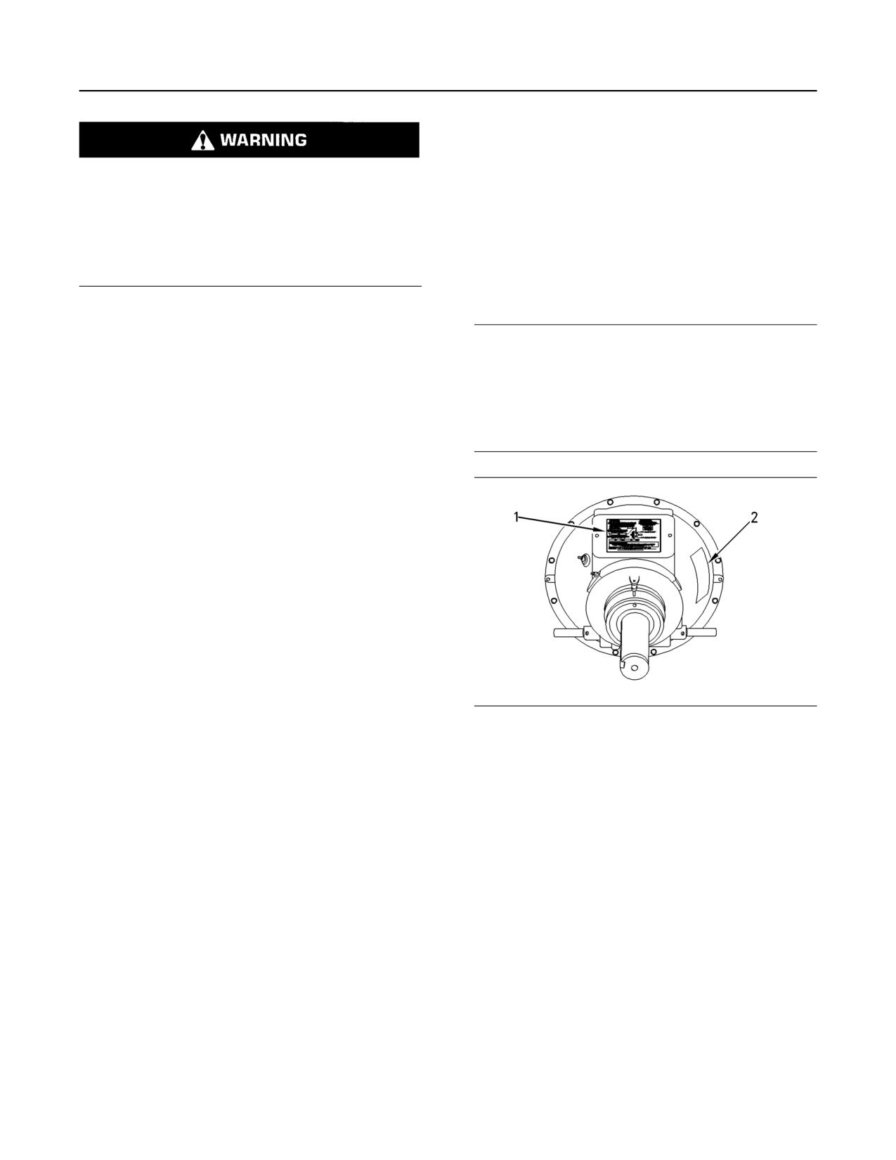
SEBU8598
91
Maintenance Recommendations
Power Take-Off Clutch - Check
S·O·S Coolant Analysis (Level 2) provides a report of
the results of both the analysis and the maintenance
recommendations.
Personal injury can result from air pressure.
For more information about coolant analysis, see your
Personal injury can result without following prop-
Caterpillar dealer.
er procedure. When using pressure air, wear a
protective face shield and protective clothing.
i03901481
Maximum air pressure at the nozzle must be less
than 205 kPa (30 psi) for cleaning purposes.
Power Take-Off Clutch - Check
SMCS Code: 3055-535
6. Dry the oil cooler core with compressed air. Direct
the air in the reverse direction of the normal flow.
NOTICE
7. Inspect the components in order to ensure
New power take-offs should have the clutch adjust-
cleanliness. The oil cooler core should be pressure
ment checked before being placed into service. The
tested. Repair the oil cooler core, if necessary.
clutch adjustment should be checked again after the
Install the oil cooler core.
first ten hours of operation. New clutch plates have a
“wear in” period, and the clutch may require several
For more information about cleaning the cores,
adjustments until the new plates are “worn in”.
consult your Caterpillar dealer.
Obtain Coolant Analysis
The concentration of supplemental coolant additive
(SCA) should be checked regularly with test kits or
with S·O·S Coolant Analysis (Level 1). Further
coolant analysis is recommended when the engine is
overhauled.
For example, considerable deposits are found in the
water jacket areas on the external cooling system, but
the concentrations of coolant additives were carefully
maintained. The coolant water probably contained
minerals that were deposited on the engine over time.
A coolant analysis can be conducted in order to verify
the condition of the water that is being used in the
cooling system. A full water analysis can be obtained
Illustration 65
g00781502
by consulting your local water utility company or an
(1) Instruction plate
agricultural agent. Private laboratories are also
(2) Serial number plate
available for water analysis.
Check the clutch adjustment regularly after “wear in”.
Caterpillar Inc. recommends an S·O·S Coolant
Heavy-duty applications which have engagements
Analysis (Level 2).
that are frequent and relatively long periods of clutch
slippage require more frequent adjustment than light-
duty applications. The operating torque should be
S·O·S Coolant Analysis (Level 2)
measured in order to determine if a clutch adjustment
is required.
An S·O·S Coolant Analysis (Level 2) is a
comprehensive coolant analysis which completely
Refer to the OEM information and instruction plate (1)
analyzes the coolant and the effects on the cooling
for instructions on lubrication, adjustment, and other
system. An S·O·S Coolant Analysis (Level 2)
recommendations for service. Perform the
provides the following information:
maintenance that is specified on the instruction plate.
• Complete S·O·S Coolant Analysis (Level 1)
• Visual inspection of properties
• Identification of metal corrosion
• Identification of contaminants
• Identification of built up impurities (corrosion and
scale)
92
SEBU8598
Maintenance Recommendations
Radiator - Clean
Inspect the fins for damage. Bent fins may be opened
with a “comb”. Inspect these items for good condition:
welds, mounting brackets, air lines, connections,
Do not operate the engine with the Instruction
clamps and seals. Make repairs, if necessary.
Plate cover removed from the clutch. Personal in-
jury may result.
i00651416
If the clutch is damaged to the point of burst fail-
ure, expelled pieces can cause personal injury to
Starting Motor - Inspect
anyone in the immediate area. Proper safeguards
SMCS Code: 1451-040; 1453-040
must be followed to help prevent accidents.
Caterpillar Inc. recommends a scheduled inspection
of the starting motor. If the starting motor fails, the
i04020194
engine may not start in an emergency situation.
Check the starting motor for proper operation. Check
Radiator - Clean
the electrical connections and clean the electrical
SMCS Code: 1353-070
connections. Refer to the Service Manual for more
information on the checking procedure and for
specifications or consult your Caterpillar dealer for
Note: Adjust the frequency of cleaning according to
assistance.
the effects of the operating environment.
Inspect the radiator for these items: damaged fins,
i03965991
corrosion, dirt, grease, insects, leaves, oil and other
debris. Clean the radiator, if necessary.
Valve Actuators - Check
SMCS Code: 1105-535
The valve actuators should be inspected and
Personal injury can result from air pressure.
adjusted when adjustments to the following
components occur.
Personal injury can result without following prop-
er procedure. When using pressure air, wear a
• Valves
protective face shield and protective clothing.
• Injectors
The maximum air pressure for cleaning purposes
must be reduced to 205 kPa (30 psi) when the air
• Compression brakes
nozzle is deadheaded.
Contact your Cat dealer for the proper procedure.
Pressurized air is the preferred method for removing
loose debris. Direct the air in the opposite direction of
i01185304
the air flow. Hold the nozzle approximately 6 mm
(0.25 inch) away from the fins. Slowly move the air
Walk-Around Inspection
nozzle in a direction that is parallel with the tubes.
This movement will remove debris that is between the
SMCS Code: 1000-040
tubes.
Inspect the Engine for Leaks and
Pressurized water may also be used for cleaning. The
maximum water pressure for cleaning purposes must
for Loose Connections
be less than 275 kPa (40 psi). Use pressurized water
in order to soften mud. Clean the core from both
A walk-around inspection should only take a few
sides.
minutes. When the time is taken to perform these
checks, costly repairs and accidents can be avoided.
Use a degreaser and steam for removal of oil and
grease. Clean both sides of the core. Wash the core
For maximum engine service life, make a thorough
with detergent and hot water. Thoroughly rinse the
inspection of the engine compartment before starting
core with clean water.
the engine. Look for items such as oil leaks or coolant
leaks, loose bolts, worn belts, loose connections and
After cleaning, start the engine and accelerate the
trash buildup. Make repairs, as needed:
engine to high idle rpm. This procedure will help in the
removal of debris and drying of the core. Stop the
engine. Use a light bulb behind the core in order to
inspect the core for cleanliness. Repeat the cleaning,
if necessary.
SEBU8598
93
Maintenance Recommendations
Walk-Around Inspection
• The guards must be in the proper place. Repair
•
Drain the water and the sediment from fuel tanks
damaged guards or replace missing guards.
on a daily basis in order to ensure that only clean
fuel enters the fuel system.
• Wipe all caps and plugs before the engine is
serviced in order to reduce the chance of system
•
Inspect the wiring and the wiring harnesses for
contamination.
loose connections and for worn wires or frayed
wires.
NOTICE
•
Inspect the ground strap for a good connection
For any type of leak (coolant, lube, or fuel) clean up
and for good condition.
the fluid. If leaking is observed, find the source and
correct the leak. If leaking is suspected, check the flu-
•
Inspect the ECM to the cylinder head ground strap
id levels more often than recommended until the leak
for a good connection and for good condition.
is found or fixed, or until the suspicion of a leak is
proved to be unwarranted.
•
Disconnect any battery chargers that are not
protected against the current drain of the starting
motor. Check the condition and the electrolyte
NOTICE
level of the batteries, unless the engine is
Accumulated grease and/or oil on an engine or deck
equipped with a maintenance free battery.
is a fire hazard. Remove this debris with steam clean-
ing or high pressure water.
•
Check the condition of the gauges. Replace any
gauges that are cracked. Replace any gauge that
can not be calibrated.
• Ensure that the cooling lines are properly clamped
and that the cooling lines are tight. Check for
leaks. Check the condition of all pipes.
• Inspect the water pumps for coolant leaks.
Note: The water pump seal is lubricated by coolant in
the cooling system. It is normal for a small amount of
leakage to occur as the engine cools down and the
parts contract.
Excessive coolant leakage may indicate the need to
replace the water pump seal. For the removal of
water pumps and the installation of water pumps and/
or seals, refer to the Service Manual for the engine or
consult your Caterpillar dealer.
• Inspect the lubrication system for leaks at the front
crankshaft seal, the rear crankshaft seal, the oil
pan, the oil filters and the valve cover.
• Inspect the fuel system for leaks. Look for loose
fuel line clamps or for loose fuel line tie-wraps.
• Inspect the piping for the air inlet system and the
elbows for cracks and for loose clamps. Ensure
that hoses and tubes are not contacting other
hoses, tubes, wiring harnesses, etc.
• Inspect the alternator belt and the accessory drive
belts for cracks, breaks or other damage.
Belts for multiple groove pulleys must be replaced as
matched sets. If only one belt is replaced, the belt will
carry more load than the belts that are not replaced.
The older belts are stretched. The additional load on
the new belt could cause the belt to break.
94
SEBU8598
Warranty Section
Emissions Warranty Information
A detailed explanation of the Emission Control
Warranty Section
Warranty that is applicable to new non-road and
stationary diesel engines, including the components
covered and the warranty period, is found in a
Warranty Information
supplemental Special Publication. Consult your
authorized Cat dealer to determine if your engine is
subject to an Emission Control Warranty and to
i05627331
obtain a copy of the applicable Special Publication.
Emissions Warranty
Information
SMCS Code: 1000
The certifying engine manufacturer warrants to the
ultimate purchaser and each subsequent purchaser
that:
1. New non-road diesel engines and stationary diesel
engines less than 10 liters per cylinder (including
Tier 1 and Tier 2 marine engines < 37 kW, but
excluding locomotive and other marine engines)
operated and serviced in the United States and
Canada, including all parts of their emission control
systems (“emission related components”), are:
a. Designed, built, and equipped so as to
conform, at the time of sale, with applicable
emission standards prescribed by the United
States Environmental Protection Agency
(EPA) by way of regulation.
b. Free from defects in materials and
workmanship in emission-related components
that can cause the engine to fail to conform to
applicable emission standards for the warranty
period.
2. New non-road diesel engines (including Tier 1 and
Tier 2 marine propulsion engines < 37 kW and Tier
1 through Tier 4 marine auxiliary engines < 37 kW,
but excluding locomotive and other marine
engines) operated and serviced in the state of
California, including all parts of their emission
control systems (“emission related components”),
are:
a. Designed, built, and equipped so as to
conform, at the time of sale, to all applicable
regulations adopted by the California Air
Resources Board (ARB).
b. Free from defects in materials and
workmanship which cause the failure of an
emission-related component to be identical in
all material respects to the component as
described in the engine manufacturer's
application for certification for the warranty
period.

SEBU8598
95
Reference Information Section
Engine Rating Conditions
Table 13
Reference Information
Engine Rating Information
Section
Time at Rated Load(1)
Perform-
Load
Examples of
ance
Factor
Any One
Applications
Rating
Overall
Engine Ratings
Instance
Pipe line
A
100%
100%
n/a
pumping
i01097462
Ventilation
Engine Rating Conditions
Irrigation pumps
Drilling
SMCS Code: 1000
B
85%
75%
n/a
applications
Plant air
All engine ratings are based on “SAE J1349”.
compressors
Ratings relate to the standard conditions of
Fire pumps
“AS1501”, of “ISO3046/1”, of “DIN6271”, and of
Chippers
“BS5514”.
Less than1
C
70%
50%
Rock crushers
hour
Portable air
The engine ratings are gross output ratings.
compressors
Gross Output Ratings - The total output capability
Snowgroomer
of the engine that is equipped with standard
Less than 30
Snowblowers
D
50%
10%
accessories.
minutes
Cranes
Water well drills
Standard accessories include the following
Standby centrifu-
Less than 15
components:
E
35%
5%
gal pumps
minutes
Oil well servicing
• Oil pumps
Both the overall time at rated load and the time the engine is op-
(1)
erated in any one instance must be considered.
• Fuel pumps
• Water pumps
NOTICE
Operating engines above the rating definitions can re-
Subtract the power that is required to drive auxiliary
sult in shorter service life before overhaul.
components from the gross output. This will produce
the net power that is available for the external load
(flywheel).
i03880100
Engine Rating Definitions
SMCS Code: 1000
In selecting a rating for a specific application, the
most important consideration is the time that is spent
at full throttle. These rating definitions identify the
percent of time at full throttle. The definitions also
identify the corresponding times below rated rpm.
Refer to this Operation and Maintenance Manual,
“Configuration Parameters” for information about the
rating for this engine.
Note: The examples of the applications are only for
reference. For an exact determination of the
appropriate rating, follow the OEM specifications or
consult your Caterpillar dealer.
96
SEBU8598
Customer Service
Customer Assistance
Europe, Africa, and Middle East
Customer Service
Caterpillar Overseas S.A.
76 Route de Frontenex
i03910306
P.O. Box 6000
CH-1211 Geneva 6
Customer Assistance
Switzerland
SMCS Code: 1000; 4450
Phone: 22-849-4444
Fax: 22-849-4544
USA and Canada
Far East
Caterpillar Asia Pte. Ltd.
When a problem arises concerning the operation or
7 Tractor Road
the service of an engine, the problem will normally be
Jurong, Singapore 627968
managed by the dealer in your area.
Republic of Singapore
Your satisfaction is a primary concern to Caterpillar
Phone: 65-662-8333
and to Caterpillar dealers. If you have a problem that
Fax: 65-662-8302
has not been handled to your complete satisfaction,
follow these steps:
China
Caterpillar China Ltd.
1. Discuss your problem with a manager from the
37/F., The Lee Gardens
dealership.
33 Hysan Avenue
Causeway Bay
2. If your problem cannot be resolved at the dealer
G.P.O. Box 3069
level, use the phone number that is listed below to
Hong Kong
talk with a Field Service Coordinator:
Phone: 852-2848-0333
Fax: 852-2848-0440
1-800-447-4986
Japan
The normal hours are from 8:00 to 4:30 Monday
Shin Caterpillar Mitsubishi Ltd.
through Friday Central Standard Time.
SBS Tower
10-1, Yoga 4-Chome
3. If your needs have not been met still, submit the
Setagaya-Ku, Tokyo 158-8530
matter in writing to the following address:
Japan
Phone: 81-3-5717-1150
Caterpillar Inc.
Fax: 81-3-5717-1177
Manager, Customer Service, Engine Division
Mossville Bldg AC
Japan
P.O. Box 610
Caterpillar Power Systems, Inc.
Mossville, Illinois 61552-0610
SBS Tower (14th floor)
4-10-1, Yoga
Please keep in mind: probably, your problem will
ultimately be solved at the dealership, using the
Setagaya-Ku, Tokyo 158-0097
dealership facilities, equipment, and personnel.
Phone: 81-3-5797-4300
Therefore, follow the steps in sequence when a
Fax: 81-3-5797-4359
problem is experienced.
Australia and New Zealand
Outside of the USA and of Canada
Caterpillar of Australia Ltd.
1 Caterpillar Drive
If a problem arises outside the USA and outside
Private Mail Bag 4
Canada, and if the problem cannot be resolved at the
Tullamarine, Victoria 3043
dealer level, consult the appropriate Caterpillar
Australia
office.
Phone: 03-9953-9333
Fax: 03-9335-3366
Latin America, Mexico, Carribean
Caterpillar Americas Co.
701 Waterford Way, Suite 200
Miami, FL 33126-4670
USA
Phone: 305-476-6800
Fax: 305-476-6801
SEBU8598
97
Customer Service
Ordering Replacement Parts
i01028392
Ordering Replacement Parts
SMCS Code: 4450; 7567
When replacement parts are required for this
product Caterpillar recommends using Caterpillar
replacement parts or parts with equivalent specifi-
cations including, but not limited to, physical di-
mensions, type, strength and material.
Failure to heed this warning can lead to premature
failures, product damage, personal injury or
death.
Quality Caterpillar replacement parts are available
from Caterpillar dealers throughout the world.
Caterpillar dealers' parts inventories are up-to-date.
The parts stocks include all of the parts that are
normally needed to protect your Caterpillar engine
investment.
When you order parts, please specify the following
information:
• Part number
• Part name
• Quantity
If there is a question concerning the part number,
please provide your dealer with a complete
description of the needed item.
When a Caterpillar engine requires maintenance
and/or repair, provide the dealer with all the
information that is stamped on the Information Plate.
This information is described in this Operation and
Maintenance Manual (Product Information Section).
Discuss the problem with the dealer. Inform the
dealer about the conditions of the problem and the
nature of the problem. Inform the dealer about when
the problem occurs. This will help the dealer in
troubleshooting the problem and solving the problem
faster.
98
SEBU8598
Reference Materials
Maintenance Records
Reference Materials
i05264255
Maintenance Records
SMCS Code: 1000; 4450
Caterpillar Inc. recommends the retention of accurate
maintenance records. Accurate maintenance records
can be used for the following purposes:
• Determine operating costs.
• Establish maintenance schedules for other
engines that are operated in the same
environment.
• Show compliance with the required maintenance
practices and maintenance intervals.
Maintenance records can be used for various other
business decisions that are related to engine
maintenance.
Maintenance records are a key element of a
maintenance program that is managed. Accurate
maintenance records can help your Cat dealer to fine-
tune the recommended maintenance intervals in
order to meet the specific operating situation. This
should result in a lower engine operating cost.
Records should be kept for the following items:
Fuel Consumption - A record of fuel consumption is
essential in order to determine when the load
sensitive components should be inspected or
repaired. Fuel consumption also determines overhaul
intervals.
Service Hours - A record of service hours is
essential to determine when the speed sensitive
components should be inspected or repaired.
Documents - These items should be easy to obtain,
and these items should be kept in the engine history
file. All of the documents should show this
information: date, service hours, fuel consumption,
unit number and engine serial number. The following
types of documents should be kept as proof of
maintenance or repair for warranty:
Keep the following types of documents as proof of
maintenance for warranty. Also, keep these types of
documents as proof of repair for warranty:
• Dealer work orders and itemized bills
• Owner repair costs
• Owner receipts
• Maintenance log

SEBU8598
99
Reference Materials
Maintenance Log
i01176304
Maintenance Log
SMCS Code: 1000; 4450
Table 14
Engine Model
Customer Identifier
Serial Number
Arrangement Number
Service
Quantity Of
Service Item
Date
Authorization
Hours
Fuel
100
SEBU8598
Reference Materials
Reference Material
i04785009
Lubricants
• Special Publication, PEHJ0192, “Optimizing S·O·S
Reference Material
Oil Change Intervals”
SMCS Code: 1000; 4450
• Data Sheet, PEHJ0021, “Product Data Sheet for
The following literature can be obtained through any
Cat DEO (Diesel Engine Oil) APD, EAME, LACD
Cat dealer.
Only”
Coolants
• Data Sheet, PEHJ0059, “Cat DEO (for North
America)”
• Data Sheet, PEHJ0067, “Cat ELC (Extended Life
Coolant) (Worldwide Formulation)”
• Data Sheet, PEHJ0072, “Cat DEO (Brazil Only)”
• Data Sheet, PEHP9554, “Diesel Engine
• Special Publication, PEHP6001, “How To Take A
Antifreeze/Coolant (DEAC)”
Good Oil Sample”
• Special Publication, PMEP5027, “Label - ELC
• Data Sheet, PEHP7062, “Full Synthetic Diesel
Radiator Label”
Engine Oil Data Sheet”
• Special Publication, SEBD0518, “Know Your
• Special Publication, PELJ0179, “FLU03-02
Cooling System”
Caterpillar Engine Crankcase Fluid-1
Specifications (All World Market Areas)”
Fuels
S·O·S Services
• Special Publication, SENR9620, “Improving Fuel
System Durability”
• Data Sheet, NEHP6013, “S·O·S Fluids Analysis
Products”
Greases
• Special Publication, PEHJ0191, “Cat S·O·S Fluids
• Data Sheet, NEHP6010, “Cat Ultra 5Moly Grease”
Analysis”
• Data Sheet, NEHP6011, “Arctic Platinum Grease
• Special Publication, PEHP7076, “Understanding
Spec Sheet”
S·O·S Services Tests”
• Data Sheet, NEHP6012, “Cat Desert Gold Grease”
• Data Sheet, NEHP6015, “Cat Special Purpose
Grease”
• Special Publication, PEGJ0035, “Grease Selection
Guide”
• Data Sheet, PEHJ0088, “Cat Multipurpose
Grease”
• Data Sheet, PEHP0002, “Molybdenum Grease
Data Sheet”
• Data Sheet, PEHP6002, “Cat Advanced 3Moly
Grease”
SEBU8598
101
Reference Materials
Decommissioning and Disposal
Miscellaneous
SAE International
400 Commonwealth Drive
•
Special Instruction, NENG2500, “Cat dealer
Warrendale, PA, USA 15096-0001
Service Tool Catalog”
Telephone (724) 776-4841
•
Special Publication, PECP9067, “One Safe
The “American Petroleum Institute Publication No.
Source”
1509” can be obtained from the following locations:
local technological society, local library and local
•
Special Instruction, REHS0354, “Charging System
college. If necessary, consult API at the following
Troubleshooting for All Engines”
address:
•
Special Instruction, REHS0871, “Electronic
American Petroleum Institute
Installation Guide”.
1220 L St. N.W.
Washington, DC, USA 20005
•
Special Publication, SEBF8029, “Index to
Telephone (202) 682-8000
Guidelines for Reusable Parts and Salvage
Operations”
The International Organization for Standardization
(ISO) offers information and customer service
•
Special Publication, SEBF8062, “Guideline for
regarding international standards and standardizing
Reusable Parts - Procedure to Inspect and Clean
activities. ISO can also supply information on the
following subjects that are not controlled by ISO:
Air Filters”
national standards, local standards, regulations,
•
Special Publication, SEBU6251, “Caterpillar
certification and related activities. Consult the
member of ISO in your country.
Commercial Diesel Engine Fluids
Recommendations”
International Organization for Standardization
(ISO)
•
Special Instruction, SEHS7332, “Warning Tag -
1, rue de Varembé
Danger Do Not Operate”
Case postale 56
CH-1211 Genève 20
•
Special Instruction, SEHS7633, “Battery Test
Switzerland
Procedure”
Telephone +41 22 749 01 11
•
Special Instruction, SEHS9031, “Storage
Facsimile +41 22 733 34 30
Procedure for Caterpillar Products”
E-mail central@iso.ch
web site http://www.iso.ch
•
Specifications, SENR3130, “Torque Specifications
Module”
European classifications are established by the
Counseil International Des Machines a Combustion
(CIMAC) (International Council on Combustion
•
Service Manual, SENR9840, “C15 and C18
Industrial Engines”
Engines).
•
Special Instruction, SMHS7001, “Assembly of Fan
CIMAC Central Secretariat
Drive Pulley Assemblies”
Lyoner Strasse 18
60528 Frankfurt
Additional Reference Material
Germany
Telephone +49 69 6603 1567
The “Engine Fluids Data Book” can be obtained from
Facsimile +49 69 6603 1566
the following locations: local technological society,
local library and local college. If necessary, consult
i03989612
EMA at the following address:
Engine Manufacturers Associaton
Decommissioning and
Two North LaSalle Street, Suite 2200
Disposal
Chicago, IL, USA 60602
E-mail: ema@enginemanufacturers.org
SMCS Code: 1000
Telephone (312) 827-8700
When the product is removed from service, local
Facsimile (312) 827-8737
regulations for the product decommissioning will vary.
Disposal of the product will vary with local
The “Society of Automotive Engineers (SAE)
Specifications” can be found in your SAE handbook.
regulations. Consult the nearest Cat dealer for
This publication can also be obtained from the
additional information.
following locations: local technological society, local
library and local college. If necessary, consult SAE at
the following address:
102
SEBU8598
Index Section
Index
A
Coolant Sample (Level 1) - Obtain
69
Coolant Sample (Level 2) - Obtain
70
After Starting Engine
36
Cooling System Supplemental Coolant
Extended Idle at Cold Ambient Temperature
Additive (SCA) - Test/Add (Systems Which
................................................................... 36
are Filled with Conventional Coolant)
70
After Stopping Engine
44
Maintain the Proper Concentration of SCA in
Air Compressor - Check (If equipped)
60
the Coolant
71
Air Shutoff - Test
60
Crushing Prevention and Cutting Prevention .. 13
Air Tank Moisture and Sediment - Drain (If
Customer Assistance
96
Equipped)
61
Outside of the USA and of Canada
96
ARD Spark Plug - Replace (If Equipped)
59
USA and Canada
96
Installing the Spark Plug
60
Customer Service
96
Removing the Spark Plug
59
D
B
Decommissioning and Disposal
101
Battery - Recycle
61
Diesel Particulate Filter - Clean/Replace (If
Battery - Replace
61
Equipped)
71
Battery Disconnect Switch (If Equipped)
27
Diesel Particulate Filter Regeneration
37
Battery Electrolyte Level - Check
62
Modes of Regeneration
39
Battery or Battery Cable - Disconnect
62
Regeneration
37
Before Starting Engine
13, 33
Regeneration Controls
38
Belts - Inspect/Replace (If Equipped)
63
Regeneration Indicator Lamps and Controls
Single Belt
63
................................................................... 38
Two or More Belts
64
Regeneration System Warning Indicators ... 40
Burn Prevention
10
Soot Level Monitoring
39
Batteries
11
Driven Equipment - Check
72
Coolant
10
Check the Alignment
72
Oils
11
Inspect the Drive Coupling
72
Inspect the Rear Gear Train
72
C
Cold Weather Operation
42
E
Cold Weather Starting
33
Electrical System
14
Ether Injection System (If Equipped)
34
Grounding Practices
15
Compression Brake - Inspect/Adjust/
Electronic Unit Injector - Check/Replace
72
Replace
64
Emissions Certification Film
21
Coolant (DEAC) - Change
64
Emissions Warranty Information
94
Cooling Systems with Heavy Deposits or
Engaging the Driven Equipment
40
Plugging
66
Engine - Clean
73
Drain
65
Engine Air Cleaner Element (Dual Element/
Fill
66
Box Type) - Replace
73
Flush
65
Primary Filter
73
Coolant (ELC) - Change
66
Secondary Filter
74
Drain
67
Engine Air Cleaner Element (Single
Fill
67
Element) - Inspect/Clean/Replace
75
Flush
67
Inspecting Air Cleaner Elements
75
Coolant Extender (ELC) - Add
68
Servicing the Air Cleaner Elements
75
Coolant Level - Check
69
SEBU8598
103
Index Section
Engine Air Cleaner Service Indicator -
Fuel System Primary Filter (Water Separator)
Inspect (If Equipped)
76
Element - Replace
82
Test the Service Indicator
76
Replace the Element
82
Engine Diagnostics
32
Fuel System Primary Filter/Water Separator
Engine Electronics
15
- Drain
81
Engine Mounts - Inspect
77
Fuel System Secondary Filter - Replace
83
Engine Oil and Filter - Change
78
Fuel Tank Water and Sediment - Drain
84
Drain the Engine Oil
79
Drain the Water and the Sediment
84
Fill the Engine Crankcase
80
Fuel Storage Tanks
84
Replace the Oil Filter
79
Fuel Tank
84
Selection of Oil Change Interval
78
Fumes Disposal Filter Element - Replace
Engine Oil Level - Check
77
(Open Crankcase Ventilation (OCV) Filter)
84
Engine Oil Sample - Obtain
78
Obtain the Sample and the Analysis
78
G
Engine Operation
37
Engine Rating Conditions
95
General Hazard Information
7
Engine Rating Definitions
95
Containing Fluid Spillage
8
Engine Ratings
95
Dispose of Waste Properly
10
Engine Starting
14, 33
Fluid Penetration
8
Engine Stopping
14, 44
Inhalation
9
Engine Storage Procedure - Check
80
Lines, Tubes, and Hoses
9
Engine Valve Lash - Check
80
Pressurized Air and Water
8
Softwrap
10
Static Electricity Hazard when Fueling with
F
Ultra-low Sulfur Diesel Fuel
9
Features and Controls
27
General Information
16
Fire Prevention and Explosion Prevention
11
Grounding Stud - Inspect/Clean/Tighten
86
Ether
12
Fire Extinguisher
12
H
Lines, Tubes, and Hoses
13
Fluid Recommendations
45
Hoses and Clamps - Inspect/Replace
86
Coolant
49
Inspect the Hoses and the Clamps
86
Diesel Engine Oil
46
Replace the Hoses and the Clamps
87
Diesel Fuel Recommendations
47
Lubricating Grease
48
I
Foreword
4
California Proposition 65 Warning
4
Important Safety Information
2
Literature Information
4
Maintenance
4
Maintenance Intervals
4
L
Operation
4
Lifting and Storage
23
Overhaul
4
Safety
4
Fuel and the Effect from Cold Weather
42
M
Fuel Conservation Practices
41
Maintenance Interval Schedule (C15
Fuel Priming Pump - Replace
81
Engines With Ratings Greater Than 579
Fuel Related Components in Cold Weather
42
hp)
55
Fuel Filters
42
Daily
55
Fuel Heaters
43
Every 12 000 Service Hours or 6 Years
56
Fuel Tanks
42
Every 2000 Service Hours
56
Fuel System - Prime
81
104
SEBU8598
Index Section
Every 2000 Service Hours or 1 Year
56
Every 250 Service Hours
58
Every 250 Service Hours
56
Every 2500 Service Hours
58
Every 2500 Service Hours
56
Every 3000 Service Hours or 3 Years
59
Every 3000 Service Hours or 3 Years
56
Every 4000 Service Hours
59
Every 4000 Service Hours
56
Every 500 Service Hours
58
Every 500 Service Hours
56
Every 5000 Service Hours
59
Every 5000 Service Hours
56
Every 6000 Service Hours or 3 Years
59
Every 585 000 L (154 540 US gal) of Fuel or
Every 760 000 L (200 770 US gal) of Fuel or
10 000 Service Hours
56
10 000 Service Hours
59
Every 6000 Service Hours or 3 Years
56
When Required
58
Initial 500 Service Hours
56
Maintenance Log
99
When Required
55
Maintenance Recommendations
51
Maintenance Interval Schedule (C15
Maintenance Records
98
Engines)
54
Maintenance Section
45
Daily
54
Manual Stop Procedure
44
Every 12 000 Service Hours or 6 Years
55
Model View Illustrations
16
Every 2000 Service Hours
54
Monitoring System
27
Every 2000 Service Hours or 1 Year
54
Indicators and Gauges
27
Every 250 Service Hours
54
Mini Industrial Power Display (MIPD)
29
Every 2500 Service Hours
54
Mounting and Dismounting
13
Every 3000 Service Hours or 3 Years
55
Every 4000 Service Hours
55
O
Every 500 Service Hours
54
Every 5000 Service Hours
55
Operation Section
23
Every 585 000 L (154 540 US gal) of Fuel or
Ordering Replacement Parts
97
10 000 Service Hours
55
Overhaul Considerations
88
Every 6000 Service Hours or 3 Years
55
Oil Consumption as an Overhaul Indicator .. 89
When Required
54
Overhaul Recommendation
89
Maintenance Interval Schedule (C18
Engines With Ratings Greater Than 760
P
HP)
56
Daily
57
Plate Locations and Film Locations
20
Every 12 000 Service Hours or 6 Years
57
Power Take-Off Clutch - Check
91
Every 2000 Service Hours
57
Product Description
17
Every 2000 Service Hours or 1 Year
57
Engine Description
17
Every 250 Service Hours
57
Product Identification Information
20
Every 2500 Service Hours
57
Product Information Section
16
Every 3000 Service Hours or 3 Years
57
Product Lifting
23
Every 4000 Service Hours
57
Clean Emission Module Lifting
23
Every 500 Service Hours
57
Engine Lifting with a Fuel Tank
23
Every 6000 Service Hours or 3 Years
57
Product Storage
24
Every 760 000 L (200 770 US gal) of Fuel or
Removal from Storage
25
10 000 Service Hours
57
Storage (Less Than One Year)
24
Initial 500 Service Hours
57
When Required
57
R
Maintenance Interval Schedule (C18
Engines)
58
Radiator - Clean
92
Daily
58
Radiator Restrictions
42
Every 12 000 Service Hours or 6 Years
59
Reference Information
21
Every 2000 Service Hours
58
Reference Information Section
95
Every 2000 Service Hours or 1 Year
58
Reference Material
100
SEBU8598
105
Index Section
Additional Reference Material
101
W
Coolants
100
Walk-Around Inspection
92
Fuels
100
Inspect the Engine for Leaks and for Loose
Greases
100
Connections
92
Lubricants
100
Warranty Information
94
Miscellaneous
101
Warranty Section
94
S·O·S Services
100
Welding on Engines with Electronic Controls.. 51
Reference Materials
98
Refill Capacities
45
Coolant Refill Capacity
45
Lubricant Refill Capacity
45
S
Safety Messages
5
Sulfuric Acid Burn (2)
6
Universal Warning (1)
6
Safety Section
5
Self-Diagnostics
32
Severe Service Application
52
Improper Maintenance Procedures
(Maintenance Procedures Which May
Contribute to a Severe Service Application)
................................................................... 53
Severe Environmental Factors
52
Severe Operating Conditions
53
Starting Motor - Inspect
92
Starting the Engine
34
Problems with the Wiring Harness
35
Starting Problems
35
Starting the Engine
34
Starting with Jump Start Cables (Do Not
Use This Procedure in Hazardous
Locations that have Explosive
Atmospheres)
35
System Pressure Release
51
Coolant System
51
Engine Oil
51
Fuel System
51
T
Table of Contents
3
V
Valve Actuators - Check
92
Product and Dealer Information
Note: For
product identification plate locations, see the section “Product Identification
Information” in the Operation and Maintenance Manual.
Delivery Date:
Product Information
Model:
Product Identification Number:
Engine Serial Number:
Transmission
Serial Number:
Generator Serial Number:
Attachment Serial Numbers:
Attachment Information:
Customer Equipment Number:
Dealer Equipment
Number:
Dealer Information
Name:
Branch:
Address:
Dealer
Phone
Hours
Contact
Number
Sales:
Parts:
Service: