FORKLIFTS CGC35S-5, CGC40S-5, CGC45S-5, CGC50C-5, CGC55C-5. Operation and Maintenance Manual
Operation &
Maintenance Manual
FORKLIFTS
CGC35S-5, CGC40S-5, CGC45S-5
CGC50C-5, CGC55C-5
FGB0A, FGB0B, FGB0C, FBGB0D, FGB0E
PSI 4.3L Tier-3
1612
WARNING
A MOVING VEHICLE CAN BE DANGEROUS
You or others around you can be seriously injured or even
killed if you are not careful or don’t know how to use this truck
correctly.
Do not operate this truck unless you are trained and autho-
rised.
Read and obey all warnings and instructions in this Manual*
and on the truck.
Make sure the truck is in good working order.
Head, arms, hands or legs outside the operator area can be
pinned or crushed when ever the truck is moving. Stay within
the operator area and stop completely before getting off.
A dockboard can move or drop while you are on it. Or you
could drive off a dock. Falls from docks or dockboards can
cause serious injury or even death. Make sure you are safe.
* Additional copies of this Operator Manual and all Truck
Labels can be obtained from Crown Equipment Corporation
New Bremen, Ohio 45869 U.S.A.
Table of Contents
Table of Contents
Information Section
Maintenance Section
Foreword
2
Jacking Information
100
Inspection, Maintenance and Repair of Lift Truck
Forks
102
Safety Section
Torque Specifications
106
Cooling System Specifications
108
Important Safety Information
4
Fuel Specifications
110
Safety
5
Lubricant Specifications
111
Lubricant Viscosities and Refill Capacities
113
Warning Signs and Labels
5
General Hazard Information
10
Maintenance Intervals
114
When Required
118
Operation Information
11
Maintenance Information
14
Every 10 Service Hours or Daily
122
First 50 - 100 Service Hours or a Week
128
Burn Prevention
15
Fire or Explosion Prevention
15
Every 250 Service Hours or Monthly
133
Operator Restraint System (If Equipped)
17
Every 500 Service Hours or 3 Months
134
Avoiding Lift Truck Tipovers
21
Every 1000 Service Hours or 6 Months
143
Safety Rules
23
Every 1500 Service Hours or 9 Months
148
Every 2000 Service Hours or Yearly
151
How to Survive in a Tipover (If Operator
Restraint System Equipped)
29
Every 2500 Service Hours or 15 Months
155
General Section
Environment Protection Section
Declaration of Conformity
30
Environment Protection
157
Specifications
31
Noise and Vibration
33
Capacity Chart (Not used in Australia)
34
Index Section
Capacity Chart (with Side Shifter) (Not used in
Australia)
35
Index
158
Serial Number
38
Operator's Warning and Identification Plate
39
Operation Section
Operator’s Station and Monitoring Systems
41
Seat Switch System (If Equipped)
45
Lift Truck Controls
46
Refueling
49
Before Starting the Engine
51
Starting the Engine
53
Lift Truck Operation
84
Mono-Ped Control System (Option)
86
Auto Shift Controller ASC - 206 (Standard)
87
Operating Techniques
90
Parking the Lift Truck
94
Lift Fork Adjustment
95
Storage Information
96
Transportation Hints
97
Towing Information
99
-1-
Information Section
Foreword
Literature Information
This manual should be stored in the operator's
Photographs or illustrations guide the operator
compartment in the literature holder or seat back
through correct procedures of checking, operation
literature storage area.
and maintenance of the CROWN operator restraint
system.
This
manual
contains
safety,
operation,
transportation,
lubrication
and maintenance
SAFE and EFFICIENT OPERATION of a lift truck
information.
depends to a great extent on the skill and alertness
on the part of the operator. To develop this skill the
Some photographs or illustrations in this publication
operator should read and understand the Safe
show details or attachments that can be different
Driving Practices contained in this manual.
from your lift truck. Guards and covers might have
been removed for illustrative purposes.
Forklift trucks seldom tipover, but in the rare event
they do, the operator may be pinned to the ground
Continuing improvement and advancement of
by the lift truck or the overhead guard. This could
product design might have caused changes to your
result in serious injury or death.
lift trucks which are not included in this publication.
Operator training and safety awareness is an
Read, study and keep this manual with the lift truck.
effective way to prevent accidents, but accidents
can still happen. The CROWN operator restraint
Whenever a question arises regarding your lift truck,
system can minimise injuries. The CROWN operator
or this publication, please consult your CROWN
restraint system keeps the operator substantially
dealer for the latest available information.
within the confines of the operator’s compartment
and the overhead guard.
This manual contains information necessary for Safe
Safety
Operation. Before operating a lift truck make sure
that the necessary instructions are available and
The Safety Section lists basic safety precautions. In
understood.
addition, this section identifies the text and locations
of warning signs and labels used on the lift truck.
Read and understand the basic precautions listed in
Operation
the Safety Section before operating or performing
The Operation Section is a reference for the new
lubrication, maintenance and repair on this lift truck.
operator and a refresher for the experienced one. This
section includes a discussion of gauges, switches, lift
truck controls, attachment controls, transportation and
towing information.
Operator Restraint System (If Equipped)
Photographs and illustrations guide the operator through
This manual contains safety, operation and
correct procedures of checking, starting, operating and
maintenance information for the CROWN operator
stopping the lift truck.
restraint system. Read, study and keep it handy.
Operating techniques outlined in this publication are
basic. Skill and techniques develop as the operator
gains knowledge of the lift truck and its capabilities.
WARNING
Your CROWN truck comes equipped with an
operator restraint system. Should it become
necessary to replace the seat for any reason, it
should only be replaced with another CROWN
operator restraint system.
-2-
Information Section
Maintenance
The Maintenance Section is a guide to equipment
care. The illustrated, step-by-step instructions are
grouped by servicing intervals. Items without specific
intervals are listed under “When Required” topics.
Items in the “Maintenance Intervals” chart are
referenced to detailed instructions that follow.
Maintenance Intervals
Use the service hour meter to determine servicing
intervals. Calendar intervals shown (daily, weekly,
monthly, etc.) can be used instead of service hour
meter intervals if they provide more convenient
servicing schedules and approximate the indicated
service hour meter reading. Recommended service
should always be performed at the interval that
occurs first.
Under extremely severe, dusty or wet operating
conditions, more frequent lubrication than is
specified in the “Maintenance Intervals” chart might
be necessary.
Perform service on items at multiples of the original
requirement. For example, at “Every 500 Service
Hours or 3 Months”, also service those items listed
under “Every 10 Service Hours or Daily”.
Environment Management
Note that the Crown internal combustion engine lift
trucks are manufactured under ISO 14001 system
which is harmonized with ISO
9001. Periodic
ENVIRONMENTAL AUDITS & ENVIRONMENTAL
PERFORMANCE EVALUATIONS have been made
by internal and external inspection entities. LIFE-
CYCLE ANALYSIS has also been made throughout
the
total
product
life.
ENVIRONMENT
MANAGEMENT SYSTEM includes DESIGN FOR
ENVIRONMENT from the initial stage of the design.
ENVIRONMENT
MANAGEMENT
SYSTEM
considers environmental laws & regulations,
reduction or elimination of resource consumption as
well as environmental emission or pollution from
industrial activities, energy saving, environment-
friendly product design (lower noise, vibration,
emission, smoke, heavy metal free, ozone depleting
substance free, etc.), recycling, material cost
reduction, and even environmentally oriented
education for the employee.
-3-
Safety Section
Important Safety Information
Most accidents involving product operation, maintenance and repair are caused by failure to observe basic
safety rules or precautions. An accident can often be avoided by recognizing potentially hazardous situations
before an accident occurs. A person must be alert to potential hazards, and use common sense. Persons
must also have the necessary training, skills and tools before attempting to perform these functions.
Improper operation, lubrication, maintenance or repair of this product can be dangerous and could
result in injury or death.
Do not operate or perform any lubrication, maintenance or repair on this product, until you have read
and understood the operation, lubrication, maintenance and repair information.
Safety precautions and warnings are provided in this manual and on the product. If these hazard
warnings are not heeded, bodily injury or death could occur to you or other persons.
The hazards are identified by the “Safety Alert Symbol” and followed by a “Signal Word” such as “WARNING”
as shown below.
WARNING
The meaning of this safety alert symbol is as follows:
Attention! Become Alert! Your Safety is Involved.
The message that appears under the warning, explaining the hazard, can be either written or pictorially presented.
Operations that may cause product damage are identified by NOTICE labels on the product and in this publication.
CROWN cannot anticipate every possible circumstance that might involve a potential hazard, and common sense is
always required. The warnings in this publication and on the product are therefore not all inclusive. Before any tool,
procedure, work method or operating technique not specifically recommended by CROWN is used, you must be sure
that it is safe for you and others. You should also ensure that the product will not be damaged or made unsafe by the
operation, lubrication, maintenance or repair procedures you choose.
The information, specifications, and illustration in this publication are on the basis of information available at the time it
was written. The specifications, torques, pressures, measurements, adjustments, illustrations, and other items can
change at any time. These changes can affect the service given to the product. Obtain the complete and most current
information before starting any job. CROWN dealers have the most current information available.
-4-
Safety Section
Warning Signs and Labels
Safety
There are several specific safety signs on your lift
The safety rules and regulations in this section are
truck. Their exact location and description of the
representative of some, but not all rules and
hazard are reviewed in this section. Please take the
regulations that apply to lift trucks. Rules and
time to familiarise yourself with these safety signs.
regulations are paraphrased without representation
that they have been reproduced verbatim.
Make sure that you can read all warning and
instruction labels. Clean or replace these labels if
These fork lift trucks are built to meet Australian
you cannot read the words or see the pictures.
Standard AS2359 for Powered Industrial Trucks,
When cleaning the labels use a cloth, water and
American National Standard, ANSI B56.1 Safety
soap. Do not use solvent, gasoline, etc.
Standard for Low Lift and High Lift Trucks. Since
You must replace a label if it is damaged, missing or
regulations vary from country to country, operate
cannot be read. If a label is on a part that is replaced,
this lift truck in accordance with local regulations.
make sure a new label is installed on the replaced
part. See your dealer for new labels.
CROWN lift trucks are manufactured in accordance
with the National Fire Protection Association (NFPA)
Training Required to Operate or Service
No.
505 and the American National Standards
Institute, Inc.
/
Industrial Truck Standards
Warning
Development Foundation (ANSI/ITSDF) B56.1,
Safety Standard for Low and High Lift Trucks and,
for European models, according to the regulations
and standards laid down in EU Machinery Directive
2006/42/EC and EMC directive 2014/30/EU.
The most effective method of reducing the risk of
serious injury or death to you or others is for you to
know how to properly operate this lift truck, to be
alert and to avoid actions or conditions that could
cause accidents.
Located on the OVHG.
Do not operate a lift truck if it is in need of
maintenance, repair or appears to be unsafe in any
way. Report all unsafe conditions immediately to
WARNING
your supervisor, then contact your authorised lift
truck dealer. Do not attempt any adjustments or
Improper operation or maintenance could result
repairs unless trained and authorised to do so.
in injury or death. Do not operate or work on the
lift truck unless you are properly trained. Read
and understand the Operation and Maintenance
Manual. Additional manuals are available from
CROWN Lift Truck dealers.
This label also provides allowable lift truck capacity
information.
Located on the front side of the FCU.
-5-
Safety Section
General Warnings to Operator
14. Use extreme care when handling long, high or wide
loads to ensure stability and durability of the truck.
15. Forks should be completely under load and spread
apart as far as load permits.
16. Machine should be equipped with overhead guard
or equivalent protection. Where load requires it, use
load backrest extension. Use extreme caution if
operating without these devices.
17. Parking - Lower lifting mechanism to floor. Put
directional control or shift lever in neutral. Set
parking/secondary brake. Turn “ON - OFF” switch
off. Check wheels if machine is on incline.
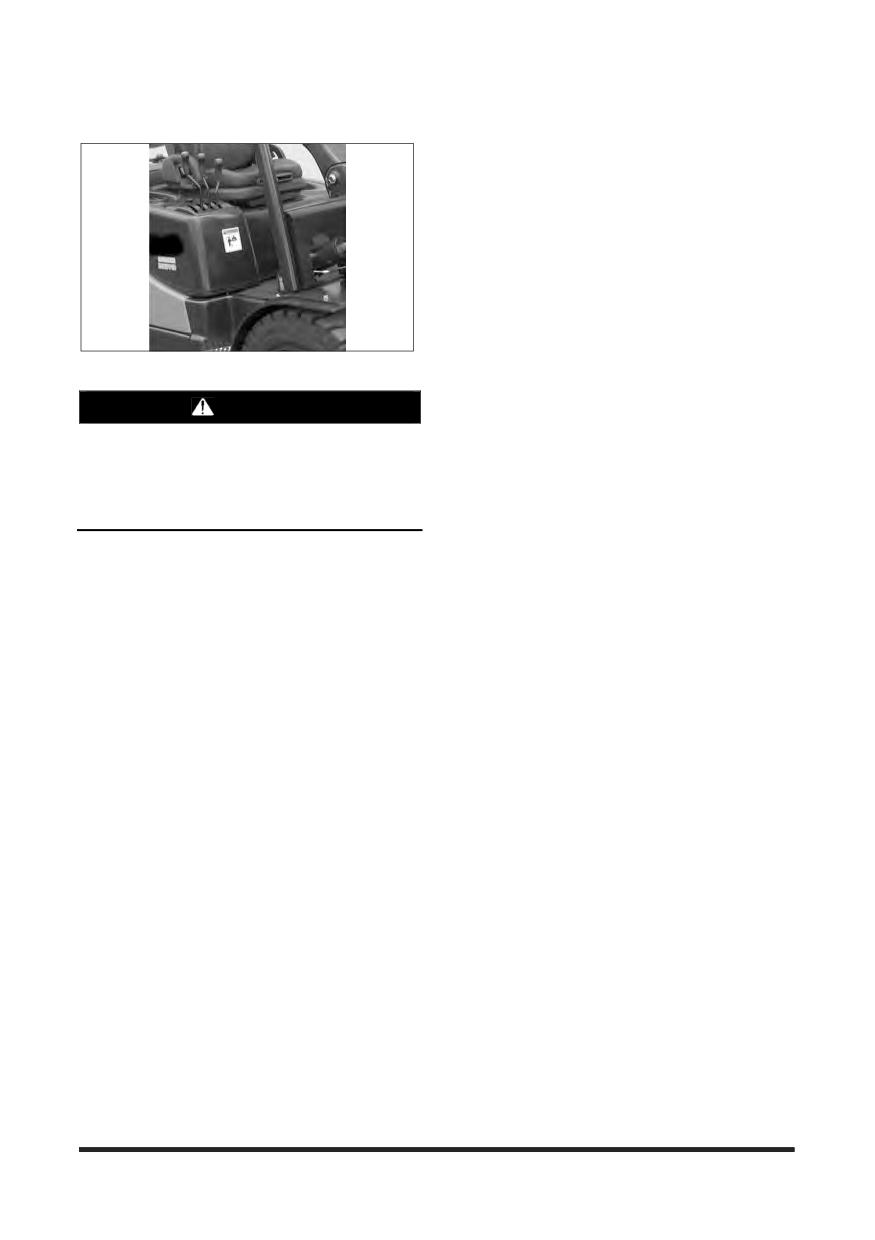
Located on the right side of the operator's seat.
Disconnect battery when storing electric machines.
18. Observe safety rules when handling fuel for engine
powered machine and when changing batteries for
WARNING
electric machines.
Only trained and authorised personnel may
19. Avoid overuse of the inching pedal as this may
operate this machine. For safe operation, read
cause the automatic transmission oil to overheat or
and follow the operation and maintenance
the clutch to slip. Do not use as a footrest or for long
Manual furnished with this lift truck and observe
periods of time.
the following warnings:
If user operates continuously pushing work or both
brake pedal and accelerator pedal were depressed
1. Before starting machine. Check all controls and
at the same time, it may cause the automatic
transmission oil to overheat or the clutch to slip.
warning devices for proper operation.
2. Refer to machine identification plate for allowable
machine capacity. Do not overload. Operate
machines equipped with attachments as partially
loaded machines when not handling a load.
3. Put directional control or shift lever in neutral before
“ON - OFF” switch is turned on.
4. Start, turn and brake smoothly. Slow down for turns,
slippery or uneven surfaces. Extremely poor
surfaces should be repaired. Avoid running over
loose objects or holes in the roadway surfaces. Use
extreme caution when turning on inclines.
5. Travel with load as low as possible and tilted back. If
load interferes with visibility, travel with load trailing.
6. On grade operations travel with load up grade.
7. Watch out for pedestrians and obstructions. Check
overhead clearances.
8. Do not permit riders on forks or machine at any time.
9. Do not allow anyone to stand or pass under the
elevated portion of any machine.
10. Be sure operating surface can safely support
machine.
11. Operate machine and attachments only from
operator's position.
12. Do not handle unstable or loosely stacked loads.
13. Use minimum tilt when picking up or depositing a
load.
-6-
Safety Section
Pressure Warning
No Standing On Forks Warning, No
Standing Under Forks Warning
WARNING
WARNING
Contents under pressure may be hot. Allow to
cool before opening.
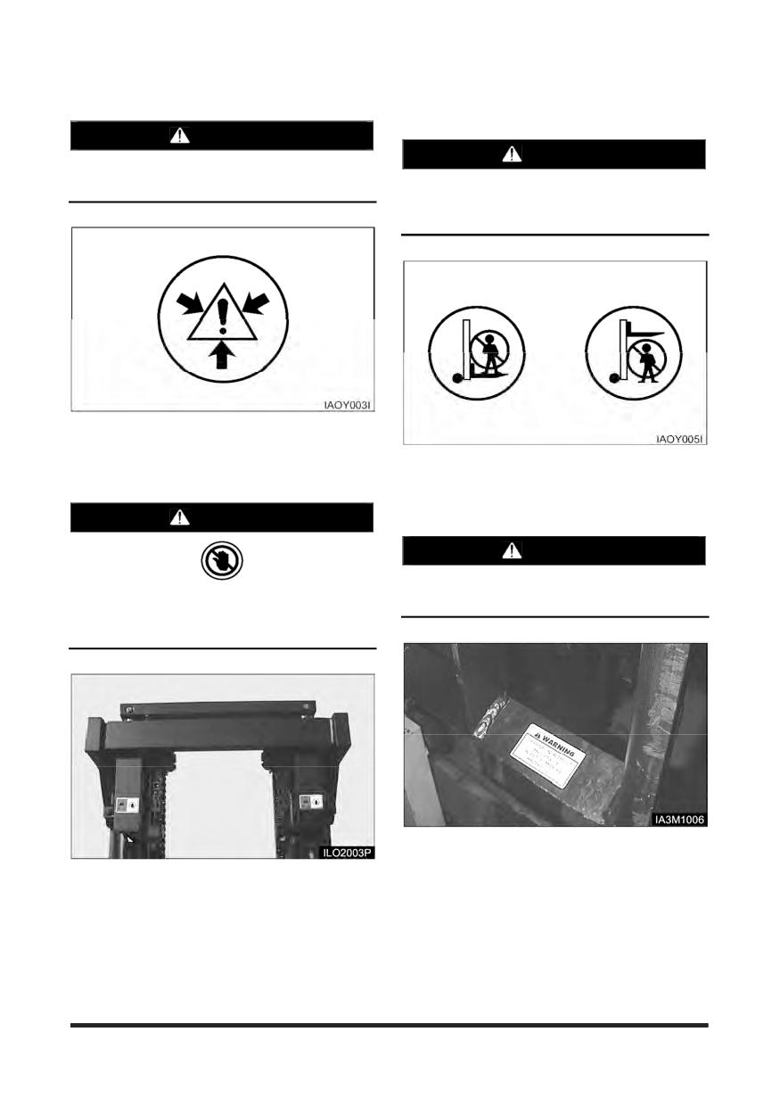
Do not stand or ride on the forks. Do not stand
or ride on a load or pallet on the forks. Do not
stand or walk under the forks.
Located on the radiator top tank by the radiator cap.
Located on the lift cylinder.
Hand Placement Warning
WARNING
Load Backrest Must Be In Place Warning
WARNING
Operation without this device in place may be
No hands. Do not place hands in this area. Do
hazardous.
not touch, lean on, or reach through the mast or
permit others to do so.
Located on the load backrest.
Located on the mast.
-7-
Safety Section
Overhead Guard Must Be In Place
Brake Pedal Adjustment Warning
Warning
WARNING
WARNING
Improper adjustment could result in injury or
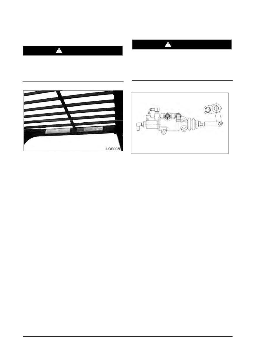
Operation without this device in place may be
death. It has to be adjusted by drawing
hazardous. This guard conforms to A.N.S.I.B56.1
dimension on free condition. For safe, don’t
and F.E.M. Section IV. This design has been
unfasten clevis and nut. It has to be adjusted by
tested with an impact of (appropriate value).
trained personnel.
(OCDB Type Only)
Located on the Overhead Guard.
Located inside Brake pedal box.
-8-
Safety Section
Parking brake
No Riders Warning
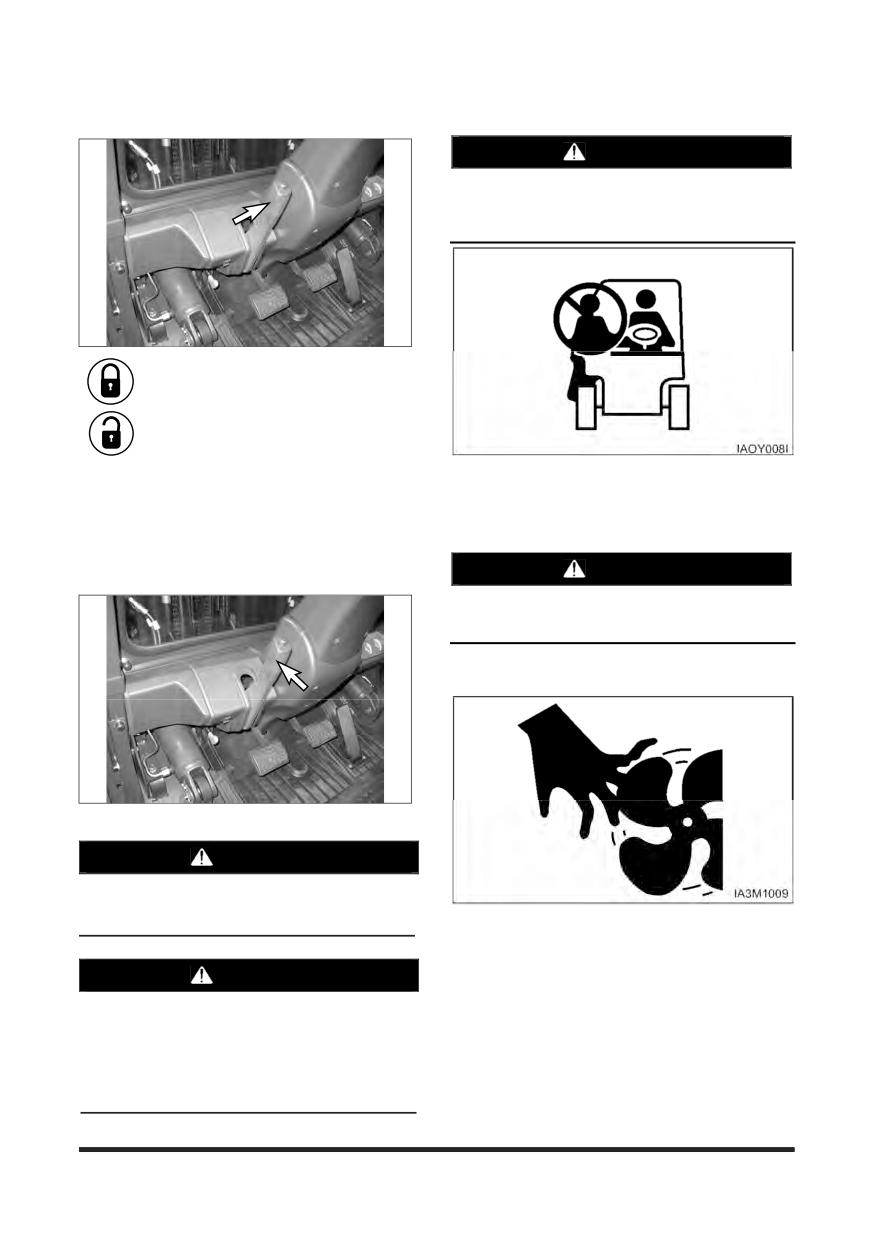
WARNING
To avoid personal injury, allow no riders. A lift
truck is designed for only one operator and no
riders.
Pull the lever BACK to engage the parking
brake.
Push the lever FORWARD to release the
parking brake.
Located beside the operator’s station.
Applying the parking brake puts the transmission in
NEUTRAL. The parking brake must be applied when
leaving the lift truck and when starting the engine. If
Moving Fan Warning
the operator leaves the seat without applying the
parking brake, an audible alarm will sound.
WARNING
To avoid personal injury, stay clear of moving
fan.
WARNING
When leaving machine apply parking brake!
Parking brake is not automatically applied.
Alarm will sound if parking brake is not applied.
Located on the shroud and upper cover.
WARNING
Correct adjustment is necessary to provide
adequate braking. See the MAINTENANCE
section for adjustment procedures. The lift truck
may creep at engine idle and can cause damage,
injury or death. Always apply the parking brake
when leaving the lift truck. The parking brake is
NOT automatically applied.
-9-
Safety Section
Do not raise loads any higher than necessary and
General Hazard Information
never raise a load higher than 1830 mm (72 in) with
the overhead guard removed.
Always use load backrest extension when the
carriage or attachment does not fully support the
load.
The load backrest extension is intended to prevent
the load or any part of the load from falling
backwards into the operator's station.
When operation the lift truck, do not depend only on
flashing lights or back-up alarm (if equipped) to warn
pedestrians.
Always be aware of pedestrians and do not proceed
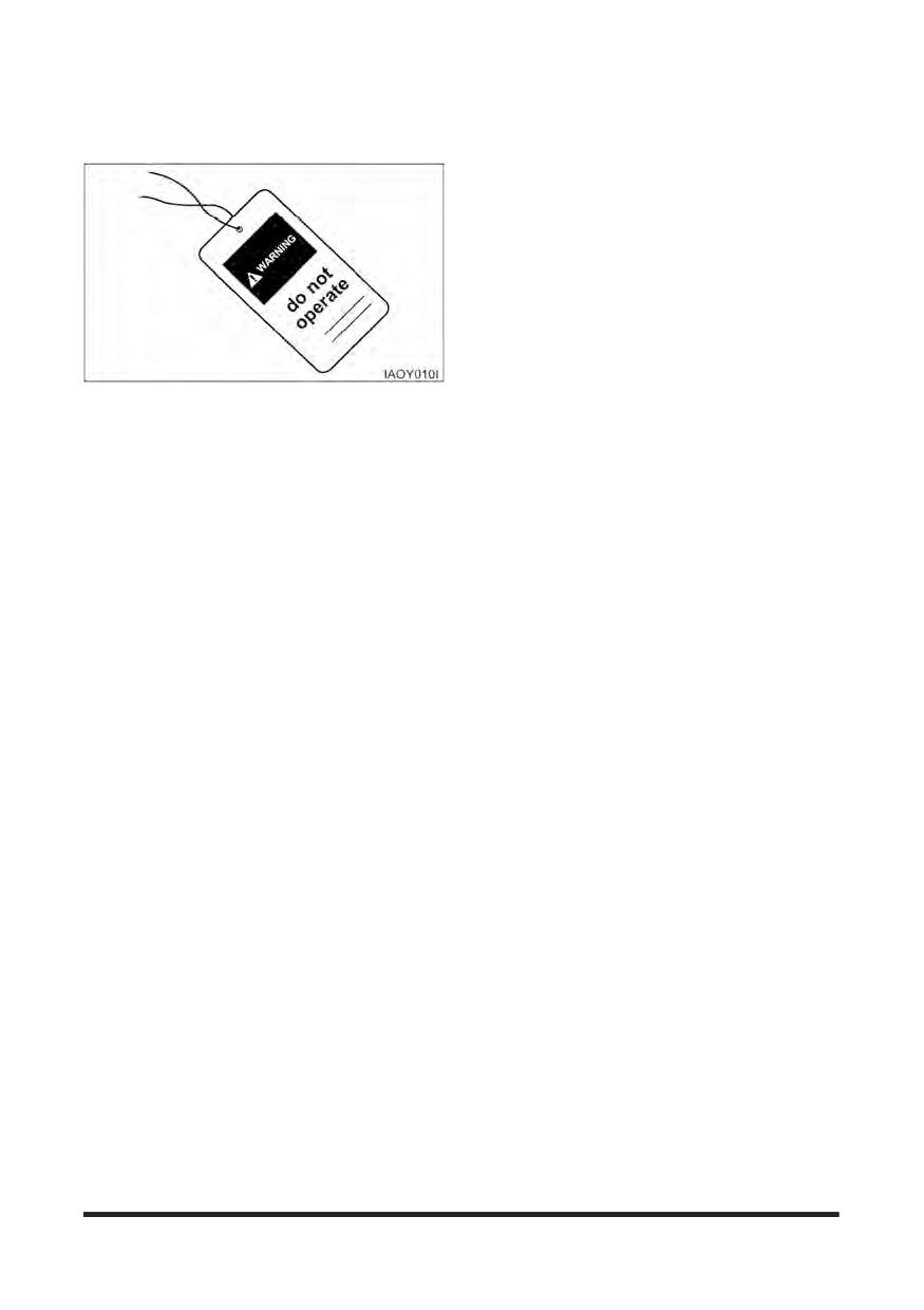
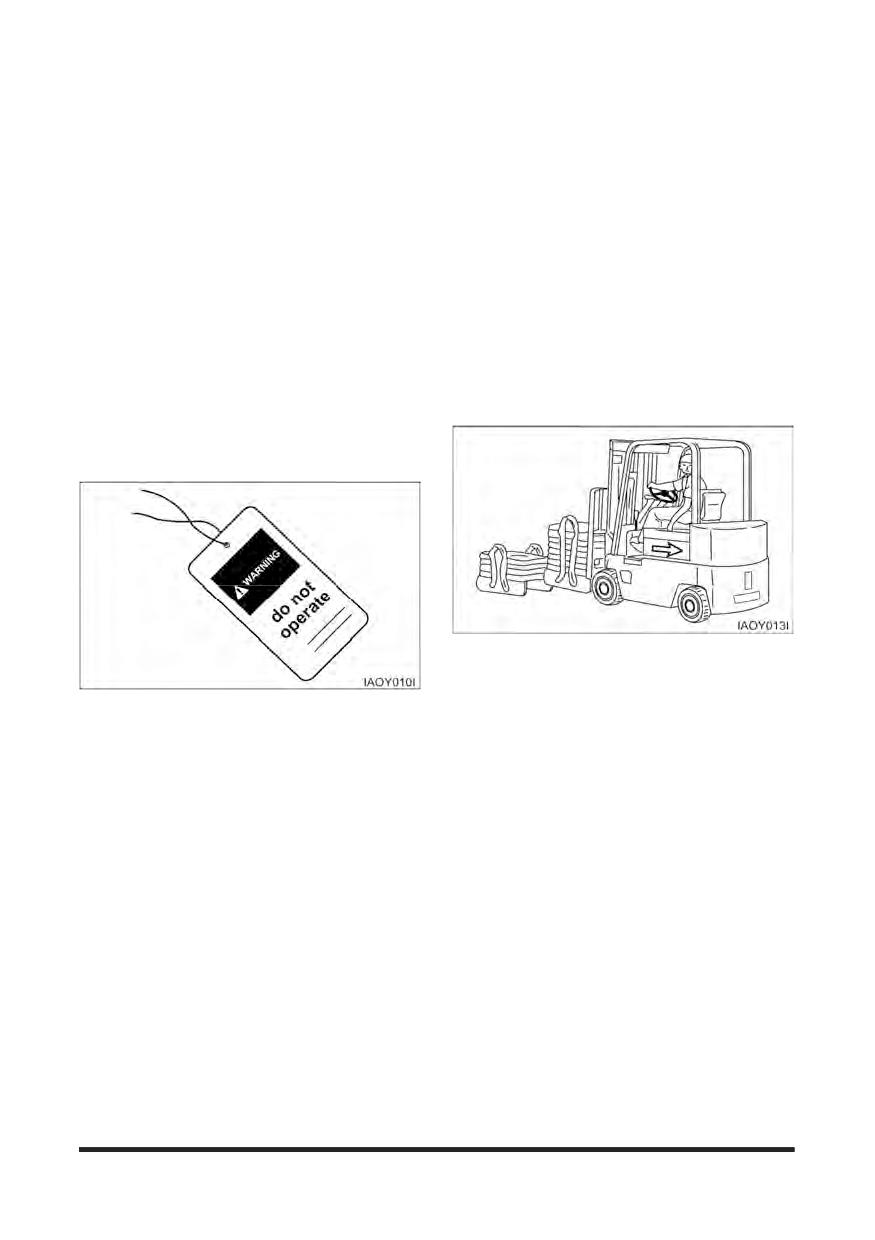
Attach a “Do Not Operate” or similar warning tag to
until the pedestrians are aware of your presence
start switch or controls before servicing or repairing
and intended actions and have moved clear of the
the lift truck.
lift truck and/or load.
Do not start or service the lift truck when a “DO NOT
Do not drive lift truck up to anyone standing in front
OPERATE” or similar warning tag is attached to the
of an object.
start switch or controls.
Obey all traffic rules and warning signs.
Wear a hard hat, protective glasses and other
protective equipment as required by job conditions.
Keep hands, feet and head inside the operator
station. Do not hold onto the overhead guard while
Know the width of your attachments so proper
operating the lift truck. Do not climb on any part of
clearance can be maintained when operating near
the mast or overhead guard or permit others to do
fences, boundary obstacles, etc.
so.
Do not wear loose clothing or jewelry that can catch
Do not allow unauthorised personnel to ride on the
on controls or other parts of the lift truck.
forks or any other part of the lift truck, at any time.
When working in a building or dock, observe floor
Keep the lift truck, especially the deck and steps,
load limits and overhead clearances.
free of foreign material such as debris, oil tools and
other items which are not part of the lift truck.
Inhaling Freon gas through a lit cigarette or other
smoking method or inhaling fumes released from a
Secure all loose items such as lunch boxes, tools
flame contacting Freon can cause bodily harm or
and other items which are not part of the lift truck.
death. Do not smoke when servicing air conditioners
or wherever Freon gas may be present.
Know the appropriate work-site hand signals and
who gives them. Accept signals from one person
Never put maintenance fluids into glass containers.
only.
Use all cleaning solutions with care.
Always use the overhead guard. The overhead
guard is intended to protect the lift truck operator
Do not use steam, solvent, or high pressure to clean
from overhead obstructions and from falling objects.
electrical components.
A truck that is used for handing small objects or
Report all needed repairs.
uneven loads must be fitted with a load backrest.
If the lift truck must be operated without the
overhead guard in place due to low overhead
clearance, use extreme care. Make sure there is no
possibility of falling objects from any adjacent
storage or work area. Make sure the load is stable
and fully supported by the carriage and the load
backrest extension (if equipped).
-10-

Safety Section
Operation Information
Mounting and Dismounting
Mount and dismount the lift truck carefully.
Clean your shoes and wipe your hands before
mounting.
Face the lift truck when mounting and dismounting.
Use both hands face the lift truck when mounting
and dismounting.
Inspect the part of the chain that is normally
Use the handgrips for mounting and dismounting.
operated over the crosshead roller. When the chain
bends over the roller, the movement of the parts
Do not try to climb on or off the lift truck when
against each other causes wears.
carrying tools or supplies.
Inspect to be sure that chain link pins do not extend
Never get on or off a moving lift truck.
outside of the bore hole.
Do not use any controls as handholds when entering
If any single link pin is extended beyond its
or leaving the operator's station.
connecting corresponding link, it should be
suspected of being broken inside of its bore hole.
Never get on or off a moving lift truck. Never jump
off the lift truck.
Inspect the chain anchor and the anchor links for
wear.
Keep hands and steering wheel free of slippery
material.
Do not change any factory set adjustment
values(including engine rpm setting) unless you
have both authorization and training. Especially
Before Starting the Lift Truck
Safety equipment and switches may not be removed
or adjusted incorrectly. Repairs, adjustments and
Perform a walk-around inspection daily and at the
maintenances that are not correct can make a
start of each shift. Refer to the topic “Walk-around
dangerous operating condition.
Inspection” in “Every 10 Service Hours or Daily”
section of this manual.
For any checkup, repair, adjustments, maintenance
and all other work concerning your forklift truck,
Adjust the seat so that full brake pedal travel can be
please contact your CROWN dealer. We would like
obtained with the operator's back against the seat
to draw your attention to the fact that any secondary
back.
damages due to improper handling, insufficient
maintenance, wrong repairs or the use of other than
Make sure the lift truck is equipped with a lighting
original CROWN spare parts waive any liability by
system as required by conditions.
CROWN.
Make sure all hydraulic controls are in the HOLD
position.
Make sure the direction control lever is in the
NEUTRAL position.
Make sure the parking brake is engaged.
-11-
Safety Section
Make sure no one is standing and/or working on,
Operating the Lift Truck
underneath or close to the lift truck before operating
the lift truck.
Always keep the lift truck under control.
Operate the lift truck and controls only from the
Obey all traffic rules and warning signs.
operator's station.
Never leave the lift truck with the engine operating,
Make sure the lift truck horn, lights, backup alarm (if
or with the parking brake disengaged.
equipped) and all other devices are working properly.
Operate the engine only in a well ventilated area.
Check for proper operation of mast and attachments.
Lower a mast, with or without load, before turning or
Pay particular attention to unusual noises or erratic
traveling. Tip over could result. Watch out for
movement which might indicate a problem.
overhead obstructions.
Make sure service and parking brakes, steering, and
Always observe floor load limits and overhead
directional controls are operational.
clearance.
Make sure all personnel are clear of lift truck and
travel path.
Start, turn, and brake smoothly, slow down for turns,
grades, slippery or uneven surfaces.
Refer to the topic “Lift Truck Operation” in the
“Operation Section” of this manual for specific
starting instructions.
Use special care when operation on grades. Do not
angle across or turn on grades. Do not use lift truck
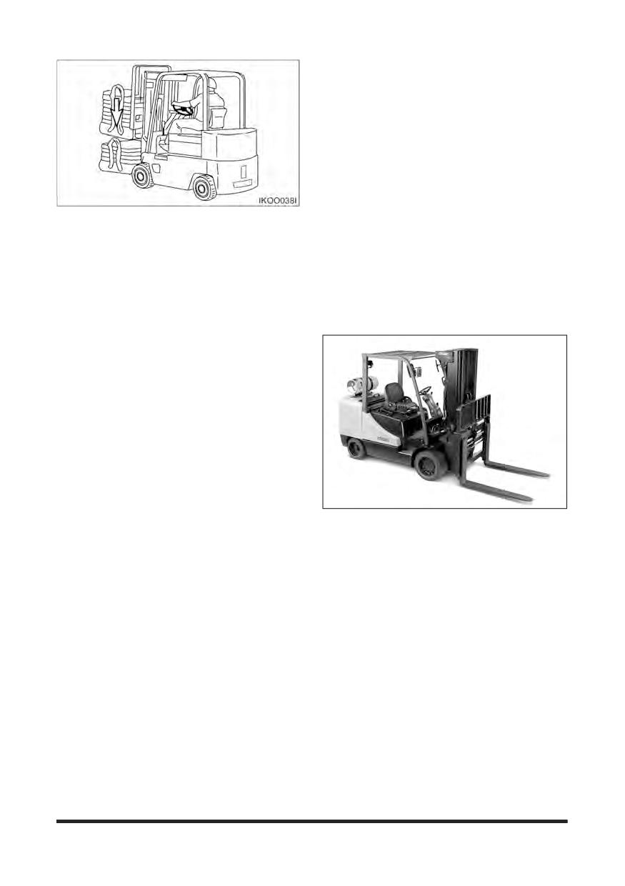
on slippery grades. Travel with forks downgrade
when unloaded. Travel with load upgrade.
Do not start the engine or move any of the controls if
there is a “DO NOT OPERATE” or similar warning
Do not overload, or handle offset, unstable, or
tag attached to the start switch or controls.
loosely stacked loads. Refer to load capacity plate
on the lift truck. Use extreme caution when handing
suspended, long, high or wide load.
Before Operating the Lift Truck
Test brakes, steering controls, horn and other
devices for proper operation. Report faulty
performance.
Do not operate lift truck until repaired.
Learn how your lift truck operates. Know its safety
devices. Know how the attachments work.
Before moving the lift truck, look around. Start, turn
and brake smoothly.
An operator must constantly observe his lift truck for
proper operation.
-12-
Safety Section
Loading or Unloading Trucks/Trailers
Do not operate lift trucks on trucks or trailers which
are not designed or intended for that purpose. Be
certain truck or trailer brakes are applied and wheel
chocks in place (or be certain unit is locked to the
loading dock) before entering onto trucks or trailers.
If trailer is not coupled to tractor, make sure the
trailer landing gear is properly secured in place. On
some trailers, extra supports may be needed to
prevent upending or corner dipping.
Tilt elevated load forward only when directly over
Be certain dock plates are in good condition and
unloading area and with load as low as possible.
properly placed and secured. Do not exceed the
rated capacity of dock boards or bridge plates.
Do not stunt ride or indulge in horseplay.
Always look and keep a clear view of the path of
travel.
Lift Truck Parking
When leaving the operator station, park the lift truck
Travel in reverse if load or attachment obstructs
visibility.
in authorised areas only. Do not block traffic.
Use extreme caution if visibility is obstructed.
Stay in designated travel path, clear of dock edges,
ditches, other drop-offs and surfaces which cannot
safely support the lift truck.
Slow down and use extra care through doorways,
intersections and other location where visibility is
reduced.
Slow down for and avoid pedestrians, other vehicles,
obstruction, pot holes and other hazards or objects
in the path of travel.
Always use overhead guards except where
operation conditions do not permit. Do not operate
lift truck in high stacking areas without overhead
guards.
Park the lift truck level, with the forks lowered
and the mast tilted forward until the fork tips
When stacking, watch for falling objects. Use load
touch the floor.
backrest extension and overhead guard.
Move the direction control lever to NEUTRAL.
Engage the parking brake.
Refer to the topic “Operation Techniques” in the
Turn the key switch off and remove the key.
“Operation Section” of this manual.
Turn the disconnect switch to OFF and remove
the key (if equipped).
Block the drive wheels when parking on an
incline.
-13-
Safety Section
Retainer pins, when struck with force, can fly out
Maintenance Information
and injure nearby persons. Make sure the area is
clear of people when driving retainer pins.
Perform all maintenance unless otherwise specified
as follows ;
Wear protective glasses when striking a retainer pin
to avoid injury to your eyes.
Park the lift truck in authorised areas only.
Park the lift truck level, with the forks lowered and
Chips or other debris can fly off objects when struck.
the mast tilted forward until the fork tips touch the
Make sure no one can be injured by flying debris
floor.
before striking any object.
Place the transmission controls in neutral.
Engage the parking brake.
Stop the engine.
Falling Objects Protective
Remove the start switch key and turn the
Structure(FOPS)
disconnect switch OFF (if equipped).
This is an attached guard located above the
Block the drive wheels when parking on an incline.
operator's compartment and secured to the lift truck.
To avoid possible weakening of the Falling Objects
Pressure Air
Protective Structure (FOPS), consult a CROWN
Pressure air can cause personal injury. When using
dealer before altering, by adding weight to, welding
pressure air for cleaning, wear a protective face
on, or cutting or drilling holes into the structure.
shield, protective clothing and protective shoes.
The overhead guard is not intended to protect
The maximum air pressure must be below 205 kPa
against every possible impact. The overhead guard
(30 psi) for cleaning purposes.
may not protect against some objects penetrating
into the operator's station from the sides or ends of
the lift truck.
Fluid Penetration
The lift truck is equipped with an overhead guard
and FOPS as standard. If there is a possibility of
Always use a board or cardboard when checking for
overhead objects falling through the guard, the
a leak. Escaping fluid under pressure, even a
guard must be equipped with smaller holes or a
pinhole size leak, can penetrate body tissue,
Plexiglas cover.
causing serious injury, and possible death. If fluid is
injected into your skin, it must be treated by a doctor
Any altering done that is not specifically authorised
familiar with this type of injury immediately.
by CROWN invalidates CROWN's FOPS
certification.
The protection offered by this FOPS will be impaired
Crushing or Cutting Prevention
if it has been subjected to structural damage.
Support equipment and attachments properly when
Structural damage can be caused by an overturn
working beneath them. Do not depend on hydraulic
accident, by falling objects, etc.
cylinders to hold it up. Any attachment can fall if a
control is moved, or if a hydraulic line breaks.
Do not mount any item such as fire extinguishers,
first aid kits and lights by welding brackets to or
Never attempt adjustments while the lift truck is
drilling holes in any FOPS structure. See your
moving or the engine is running unless otherwise
CROWN dealer for mounting guidelines.
specified.
Where there are attachment linkages, the clearance
in the linkage area will increase or decrease with
movement of the attachment.
Stay clear of all rotating and moving parts.
Keep objects away from moving fan blades.
They will throw or cut any object or tool that falls or
is pushed into them.
Do not use a kinked or frayed wire rope cable. Wear
gloves when handling the wire rope cable.
-14-
Safety Section
Burn Prevention
Fire or Explosion Prevention
Coolant
All fuels, most lubricants and some coolant mixtures
are flammable.
At operating temperature, the engine coolant is hot
and under pressure. The radiator and all lines to
Fuel leaked or spilled onto hot surfaces or electrical
heaters or the engine contain hot water or steam.
components can cause a fire.
Any contact can cause severe burns.
Do not smoke while refueling or in a refueling area.
Steam can cause personal injury.
Do not smoke in areas where batteries are charged,
Check the coolant level only after engine has been
or where flammable materials are stored.
stopped and the filler cap is cool enough to remove
with your bare hand.
Batteries in series can be located in separate
compartments.
Remove the cooling system filter cap slowly to
relieve pressure.
When using jumper cables always connect
positive(+) cable to positive(+) terminal of battery
Cooling system additive contains alkali that can
connected to starter solenoid and negative(-) cable
cause personal injury. Avoid contact with the skin
from external source to starter negative(-) terminal.
and eyes and do not drink.
(If not equipped with starter negative(-) terminal,
Allow cooling system components to cool before
connect to engine block.)
draining.
See the Operation Section of this manual for specific
starting instructions.
Oils
Clean and tighten all electrical connections. Check
daily for loose or frayed electrical wires. Have all
Hot oil and components can cause personal injury.
loose or frayed electrical wires tightened, repaired or
Do not allow hot oil or components to contact the
replaced before operation the lift truck.
skin.
Keep all fuels and lubricants stored in properly
At operation temperature, the hydraulic tank is hot
marked containers and away from all unauthorised
and can be under pressure.
persons.
Remove the hydraulic tank filter cap only after the
Store all oily rags or other flammable material in a
engine has been stopped and the filter cap is cool
protective container, in a safe place.
enough to remove with your bare hand.
Do not weld or flame cut on pipes or tubes that
Remove the hydraulic tank filter cap slowly to relieve
contain flammable fluids. Clean them thoroughly
pressure.
with nonflammable solvent before welding or flame
cutting on them.
Relieve all pressure in air, oil fuel or cooling systems
before any lines, fittings or related items are
Remove all flammable materials such as fuel, oil
disconnected or removed.
and other debris before they accumulate on the lift
truck.
Do not expose the lift truck to flames, burning brush,
Batteries
etc., if at all possible.
Batteries give off flammable fumes which can
Shields, which protect hot exhaust components from
explode.
oil or fuel spray in the event of a line, tube or seal
Do not smoke when observing the battery electrolyte
failure, must be installed correctly.
levels.
Do not operate in areas where explosive gases exist
Electrolyte is an acid and can cause personal injury
or are suspected.
if it contacts skin or eyes.
Always wear protective glasses when working with
batteries.
-15-
Safety Section
Fire Extinguisher
Have a fire extinguisher-type BC and
1.5KG
minimum capacity-on rear overhead guard leg with
latch and know how to use it. Inspect and have it
serviced as recommended on its instruction plate.
LPG
LPG is poisonous and flammable.
Breathing LPG vapors or repeated contact of LPG
with skin can cause personal injury.
Use LPG only in well-ventilated areas.
Do not smoke while changing LPG cylinders.
Use LPG with care to avoid fires.
Do not store replacement LPG cylinders in living
areas or in the operator's compartment.
Do not store LPG cylinders in direct sunlight or at
temperatures above 39°C (102°F).
Discard cylinders in a safe place. Do not puncture or
burn cylinders.
Keep LPG cylinders out of the reach of unauthorised
personnel.
Lines, Tubes and Hoses
Do not bend or strike high pressure lines. Do not
install bent or damaged lines, tubes or hoses.
Repair any loose or damaged fuel and oil lines,
tubes and hoses. Leaks can cause fires. Contact
your CROWN dealer for repair or replacement.
Check lines, tubes and hoses carefully. Do not use
your bare hand to check for leaks. Use a board or
cardboard to check for leaks. See Fluid Penetration
in the Safety Section for more details. Tighten all
connections to the recommended torque. Replace if
any of the following conditions are found.
End fittings damaged or leaking.
Outer covering chafed or cut and wire reinforcing
exposed.
Outer covering ballooning locally.
Evidence of kinking or crushing of the flexible part of
hose.
Armoring embedded in the outer cover.
End fittings displaced.
Make sure that all clamps, guards and heat shields
are installed correctly to prevent vibration, rubbing
against other parts, and excessive heat during
operation.
-16-
Safety Section
Operator Restraint System (If
Equipped)
Warning Signs and Labels
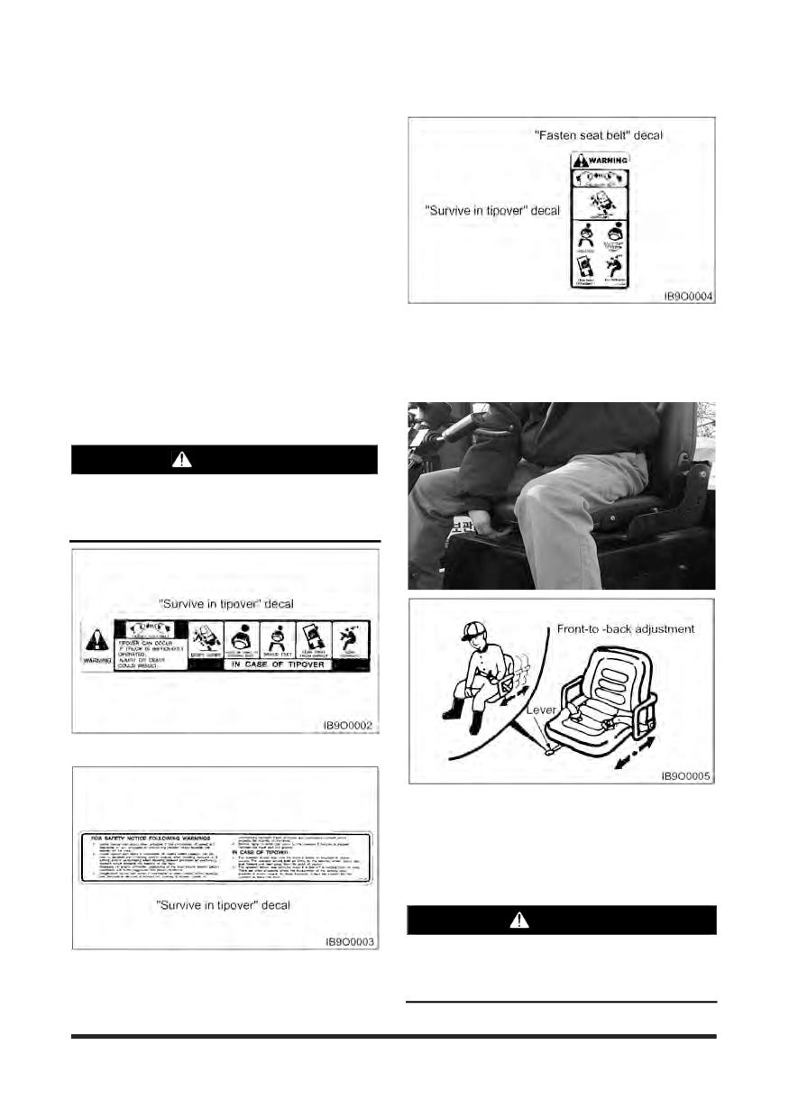
Your CROWN lift truck has the following tipover
warning decals.
Make sure that you can read all safety signs. Clean
or replace these if you cannot read the words or see
the pictures. When cleaning the labels use a cloth,
water and soap. Do not use solvent, gasoline, etc.
You must replace a label if it is damaged, missing or
cannot be read. If a label is on a part that is replaced,
make sure a new label is installed on the replaced
part. See you CROWN Lift Truck dealer for new
The “Survive in tipover” warning is located on the
labels.
overhead guard. It shows the proper use of the
operator restraint system.
The most effective method of preventing serious
injury or death to yourself or others is to familiarise
Seat Adjustment
yourself with the proper operation of the lift truck, to
be alert, and to avoid actions or conditions which
can result in an accident.
WARNING
Tipover can occur if the truck is improperly
operated. In the event of a tipover, injury or
death could result.
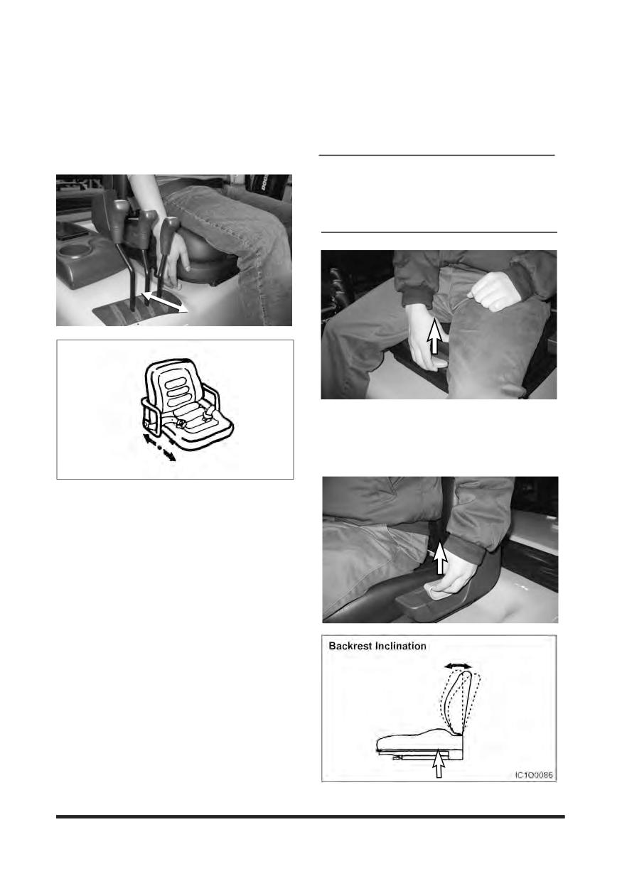
Move the lover, slide the seat to the desired position,
and release the lever.
Adjust the seat before operating the lift truck. After
adjusting, set the seat to make sure it is properly
locked. Do not adjust the seat while the truck is in
motion.
WARNING
Do not pace your hand or fingers under the seat.
Injury may occur as the seat moves up and
down.
-17-
Safety Section
If Optional Suspension Seat (weight
Weight adjustment
adjusting type) Equipped
Pull the weight adjustment lever upwards and move
right or left side.
Forward and Backward Adjustment
Adjust to driver’s weight in 7 steps (50 ~ 110 kg)
The seat can be adjusted by pushing the lever on
the right side of seat.
NOTICE
Do not place your hand or fingers under the seat.
Injury may occur as the seat moves up and down.
Forward and Backward
Adjustment
Backrest Inclination
The backrest angle can be adjusted by using the
lever on the left side of seat.
Adjust the seat before operating the lift truck. After
adjusting, set the seat to make sure it is properly
locked. Do not adjust the seat while the truck is in
motion.
-18-
Safety Section
Seat Belt
The Operator Restraint System, Prevents the
operator from jumping from the operator’s
compartment in the event of a forward or side
tipover. The system is designed to keep the operator
on the seat and in the operator’s compartment in the
event of a tipover.
3. In the event of a tipover, the seat and restraint
system should be inspected for damage and
replaced, if necessary.
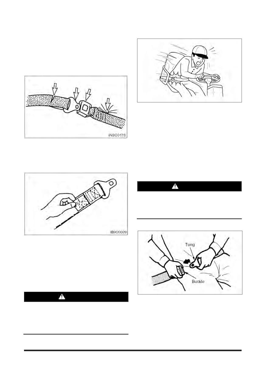
NOTE: Operator restraints shall be examined at
the regular truck service intervals. It is
recommended that they be replaced if any
of the following conditions are found:
1. If the seat belt is torn, if pulling motion is interrupted
during extension of the belt, or if the belt cannot be
Cut or frayed strap
inserted into the buckle properly, replace the seat
Worn or damaged hardware including anchor
belt assembly.
points
Buckle or retractor malfunction
Loose stitching
WARNING
The seat belt may cause the operator to bend at
the waist. If you are pregnant or have suffered
from some abdominal disease, consult a doctor
before you use the seat belt.
Fasten the Seat Belt
2. Belt Maintenance - Every 500 service hours. Check
that the belt fastening works properly and that
winding device is free from run lock when jerked.
Check that the belt is suitably fastened to the seat.
Check that the seat is correctly secured to the hood
and the chassis. On visual inspection, fastenings
must be intact, otherwise, contact the safety
manager.
WARNING
1. Grip the plate (connector) of the belt and pull the
Your CROWN truck comes equipped with a
belt from the retractor. Then insert the plate into the
CROWN operator restraint system. Should it
slot of the buckle until a snap is heard. Pull on the
become necessary to replace the seat for any
belt to confirm it is latched.
reason, it should only be replaced with another
CROWN operator restraint system.
2. Make sure the belt is not twisted.
-19-
Safety Section
WARNING
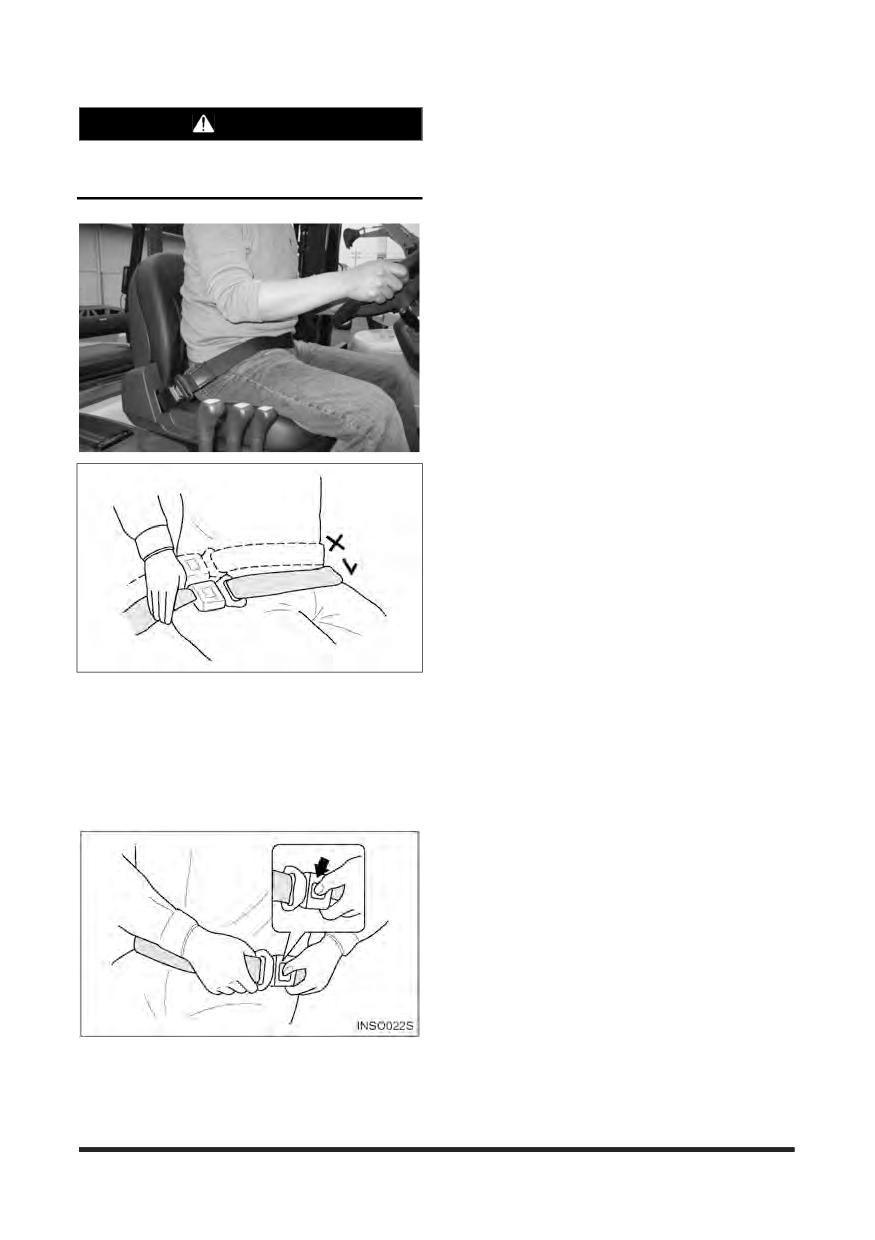
If you fasten the belt across your abdomen, the
belt may injure your abdomen in an accident.
3. Be sure to fasten the belt across your hips, not
across your abdomen.
NOTE: The belt is designed to automatically adjust
to your size and movement. A quick pull on
the belt will confirm that the automatic
adjuster will hold the belt position in the
event of an accident.
Push the button of the buckle to release the belt.
The belt will automatically retract when released.
Hold the plate of the belt and allow the belt to slowly
retract.
-20-
Safety Section
Avoiding Lift Truck Tipovers
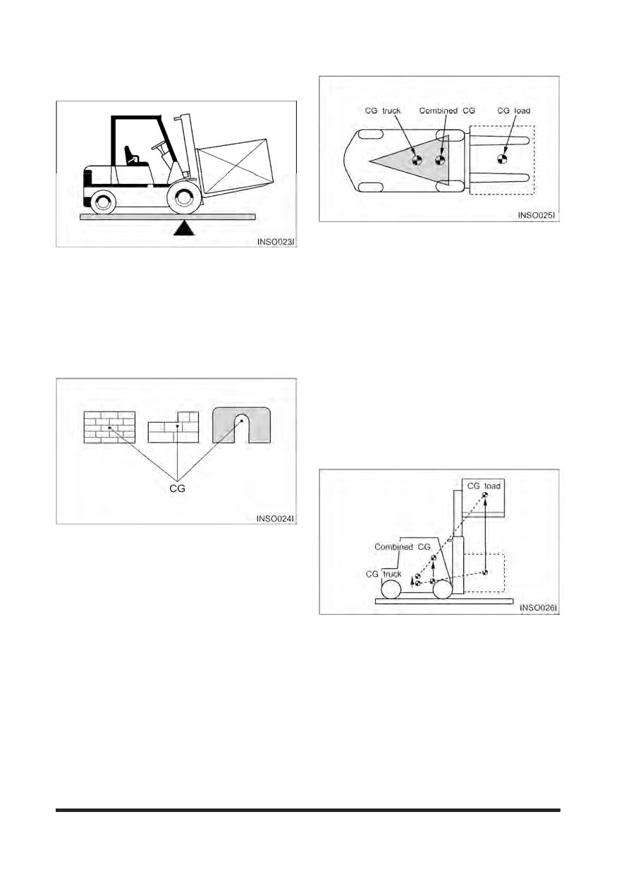
The stability of the lift truck is determined by the
location of its CG; or, if the truck is loaded, the
Counterbalanced lift truck design is based on the
combined CG of the truck and load. The lift truck
balance of two weights on opposite sides of a
has moving parts and, therefore, has a CG that
fulcrum (the front axle). The load on the forks must
moves. The CG moves forward or backward as the
be balanced by the weight of the lift truck.
mast is tilted forward or backward. The CG moves
up or down as the mast moves up or down. The CG
The location of the centre of gravity of both the truck
and, therefore, the stability of the loaded lift truck, is
and the load is also a factor. This basic principle is
affected by a number of factors such as:
used for picking up a load. The ability of the lift truck
to handle a load is discussed in terms of centre of
the size, weight, shape and position of the load
gravity and both forward and sideways stability.
the height to which the load is lifted
the amount of forward or backward tilt
tyre pressure
dynamic forces created when the lift truck is
accelerated, braked or turned
condition and grade of surfaces on which the lift
truck is operated
The point within an object, at which the whole weight
of the object may be regarded as being
concentrated, is called the centre of gravity or CG. If
the object is uniform, its geometric centre will
coincide with its CG. If it is not uniform, the CG
could be at a point outside of the object. When the
lift truck picks up a load, the truck and load have a
new combined CG.
These same factors are also important for unloaded
lift trucks. They tip over sideways easier than a
loaded lift truck carrying its load in the lowered
position.
-21-
Safety Section
The location of the CG in the vertical direction is the
same as the horizontal dimension.
Remember that, unless otherwise indicated, the
capacity load shown on the nameplate is for a
standard lift truck with standard backrest, forks and
mast, and having no special-purpose attachment. In
addition, the capacity load assumes that the load
centre is no further from the top of the forks than it is
from the face of the backrest. If these conditions do
not exist, the operator may have to reduce the safe
operating load because the truck stability may be
reduced. The lift truck should not be operated if its
capacity/nameplate does not indicate capacity load.
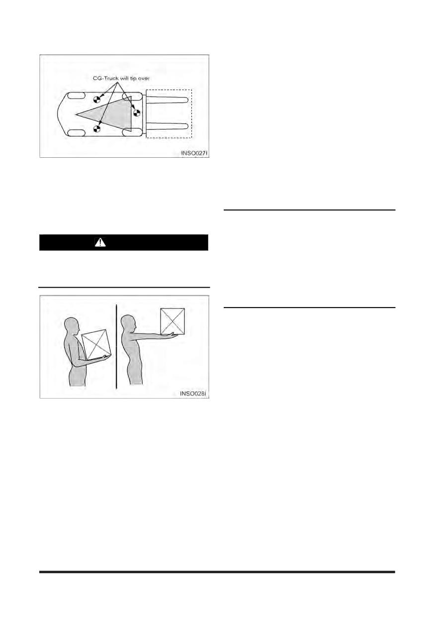
For the lift truck to be stable (not tip over forward or
to the side), the CG must stay within the area of the
NOTE: If the load is not uniform, the heaviest
lift truck stability base - a triangular area between
portion should be placed closer to the
the front wheels and the pivot of the steer wheels. If
backrest and centreed on the forks.
the CG moves forward of the front axle, the lift truck
will tip forward. If the CG moves outside of the line
on either side of the stability base, the lift truck will
NOTICE
tip to the side.
1. Capacity/Nameplates originally attached to
forklifts sold by CROWN shall not be removed,
WARNING
altered or replaced without CROWN's approval.
Dynamic forces (braking, acceleration, turning)
2. CROWN assumes no responsibility for lift trucks
also affect stability and can produce tipover
placed in service without a valid CROWN
even when the CG is within the stability triangle.
Nameplate.
3. If necessary to change your specification,
contact your CROWN lift truck dealer.
The capacity load of the lift truck is shown on the
capacity/nameplate riveted to the truck. It is
determined by the weight and load centre. The load
centre is determined by the location of the CG of the
load.
The load centre shown on the nameplate is the
horizontal distance from the front face of the forks,
or the load face of an attachment, to the CG of the
load.
-22-
Safety Section
Safety Rules
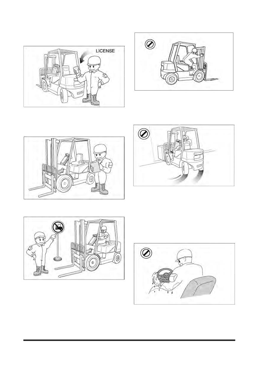
Do not operate a lift truck unless you are in the
operator’s seat. Keep hands and feet inside the
operator’s compartment. Do not put any part of the
body outside of the operator’s compartment. Never
Only properly trained and authorised personnel
should operate forklift trucks. Wear a hard hat and
put any part of body into the mast structure or
safety shoes when operating a lift truck. Do not wear
between the mast and the truck
loose clothing.
Do not start, stop, turn or change direction suddenly
or at high speed. Sudden movement can cause the
Inspect and check the condition of your forklift truck
lift truck to tip over. Slow the speed of your truck and
using the operator's check list before starting work.
use the horn near corners, exits, entrances, and
Immediately report to your supervisor any obvious
near people.
In case of a truck with the steering knob, Do not
operate the steering knob suddenly, to prevent
accident caused by quick turning.
Do not operate your truck in unauthorised areas.
Know your forklift truck and think safety. Do not
compromise safety. Follow all safety rules and read
all warning signs.
Never operate a lift truck with wet hands or shoes.
Never hold any controls with grease on your hands.
Your hands or feet will slide off of the controls and
cause an accident.
-23-
Safety Section
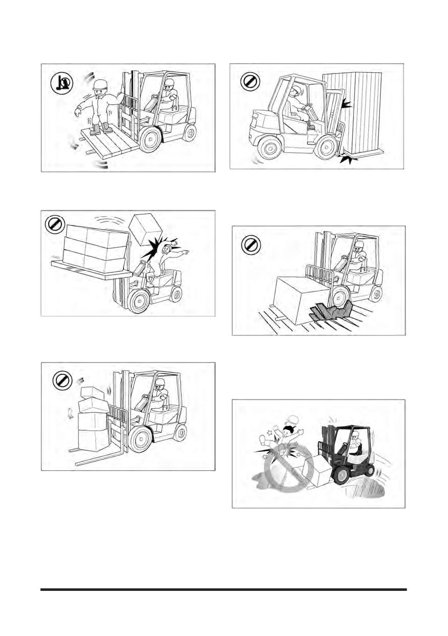
Do not raise anyone on the forks of your lift truck.
Do not overload. Always handle loads within the rated
Do not let other people ride on the truck.
capacity shown on the capacity plate.
Lift trucks are designed to carry loads, not people.
Do not add extra counterweight to the truck.
An overload can cause the truck to roll over and
cause injury to personnel and damage to the lift
Do not operate your truck without the load backrest
extension and overhead guard. Keep the load
against the backrest with the mast tilted backward.
Do not drive on soft ground.
Observe all signs, especially those on maximum
permitted floor loadings, elevator capacities and
clearance heights.
Handle loads carefully and check them closely for
stability and balance.
Do not lift or move loads that are not safe. Do not
pick up an off centre load. Such a load increases the
possibility of a tipover to the side. Make sure loads
are correctly stacked and positioned across both
forks. Always use the proper size pallet. Position the
Do not drive on slippery surfaces.
forks as wide as possible under the load. Position
Sand, gravel, ice or mud can cause a tipover. If
loads evenly on the forks for proper balance. Do not
unavoidable, slow down.
lift a load with one fork.
-24-
Safety Section
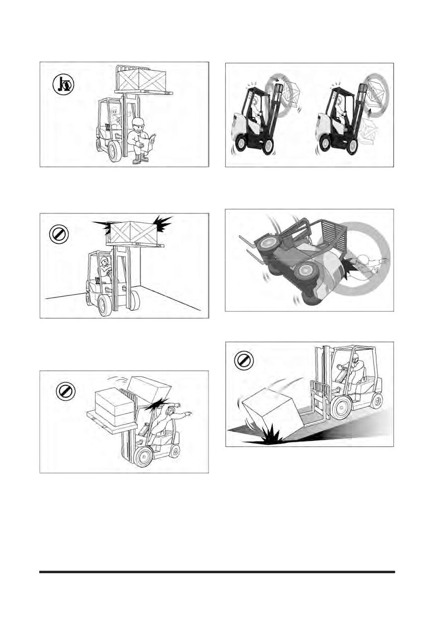
Do not permit anyone to stand or walk under the
Do not elevate the load with the mast tilted forward.
load or lifting mechanism. The load can fall and
Do not tilt the elevated loads forwards.
cause injury or death to anyone standing below.
This will cause the lift truck to tip over forward.
Do not jump off if your truck starts to tip over.
Look out for overhead obstructions when raising or
Stay in your seat to survive.
stacking loads. Do not travel with a raised load. Do
not travel with the mast raised. The lift truck can roll
over and cause injury or death to you or other
personnel.
Go up ramps in forward direction and down ramps in
reverse direction when moving loads.
Never elevate a load with the forklift truck on an incline.
Do not move loose loads that are higher than the load
Go straight off and straight down. Use an assistant
backrest.
when going up or down a ramp with a bulky load.
Be alert for falling loads when stacking.
Travel with the load tilted back and the forks as low as
possible.
This will increase stability to the truck and load and
permit better visibility for you.
-25-
Safety Section
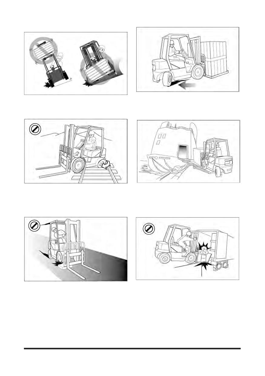
Do not stack or turn on ramps.
Do not drive in forward direction when loads restrict your
Do not attempt to pick-up or deposit a load unless the lift
visibility. Operate your lift truck in reverse to improve
truck is level. Do not turn on or drive across an incline.
visibility except when moving up a ramp.
Be careful when operating a lift truck near the edge of a
Do not go over rough terrain. If unavoidable, slow down.
loading dock or ramp. Maintain a safe distance from the
Cross railroad tracks slowly and diagonally whenever
edge of docks, ramps and platforms.
possible. A railroad crossing can give a loaded forklift
Always watch tail swing.
truck a real jolt. For smoother crossing, cross the
The truck can fall over the edge and cause injury or
railroad diagonally so one wheel crosses at a time.
death.
Do not operate on bridge plates unless they can support
Avoid running over loose objects.
the weight of the truck and load.
Look in the direction of travel. Look out for other persons
Make sure that they are correctly positioned.
or obstructions in your path of travel.
Put blocks on the vehicle you enter to keep it from
An operator must be in full control of his lift truck at all
moving.
times.
-26-
Safety Section
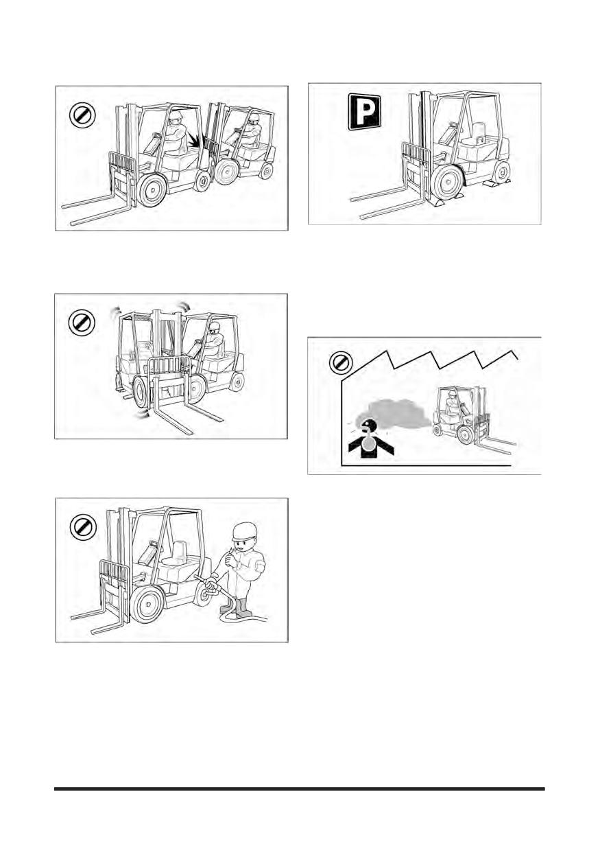
Do not operate your truck close to another truck.
Park your lift truck in authorised areas only. Fully lower
Always keep a safe distance from other trucks and
the forks to the floor, put direction lever in NEUTRAL
make sure there is enough distance to stop safely.
position, engage the parking brake, and turn the key to
Never overtake other vehicles.
the OFF position. Remove the key and put blocks
behind the wheels to prevent the truck from rolling. Shut
off your forklift truck when leaving it unattended.
Check the condition of your forklift truck after the day's
work.
Do not use your lift truck to push or tow another truck.
Do not let another push or tow your truck.
If a truck will not move, call a service technician.
Exhaust from all internal combustion engines
contains carbon monoxide, a colorless, odorless,
tasteless, poisonous gas. Exposure to carbon
monoxide can cause serious injury or health
problems, including death. And avoid unnecessary
idling of the engine. If nausea, dizziness or
headaches are experienced stop the truck and seek
fresh air.
Forklift trucks may only be refueled at specially reserved
locations. Switch off the engine when refueling.
Smoking and handling of naked flames during refueling
are strictly prohibited. This prohibition also applies
during the changing of the LPG (liquefied propane gas)
tank.
Mop up spilt fuel and do not forget to close the fuel tank
before restarting the engine.
-27-
Safety Section
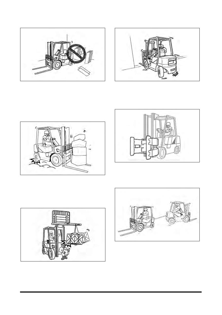
Do not operate forklifts near flammable or
An unloaded forklift may be easier to tip over than a
combustible materials.
loaded truck.
To avoid the discoloration, deformation or
When traveling without a load, the risk of lateral
combustion of materials (such as lumber, veneer
overturn is greater.
board, paper products and other similar items),
always park at least 30 cm (12 inches) away from
them.
There are many special attachments available to
replace the forks on a lift truck.
All carry safety implications and special training in
Forklift trucks are not cars. They often have small
their operation is highly recommended.
tyres, no suspension, and are very heavy.
The forklift's centre of gravity will also change when
carrying loads.
Avoid uneven bumps, pot holes and other hazards
whenever possible.
The counterweight draw bar should not be used for
towing the forklift or for towing another forklift.
Towing is only advised in emergencies, by trained
operators and at low speed, no faster than 2 km/h,
Carrying a load suspended on a chain or a cable
to a convenient location for repair.
may unbalance a truck.
Take extra care around pedestrians with a
suspended load as it may sway or even strike them.
-28-
Safety Section
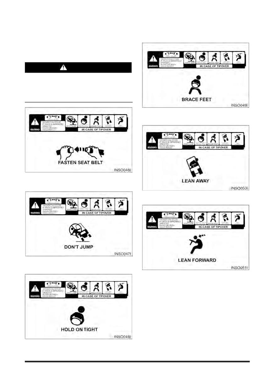
How to Survive in a Tipover (If
Operator Restraint System
Equipped)
WARNING
In the event of a tipover, the risk of serious
injury or death will be reduced if the operator is
using the operator restraint system and follows
the instructions provided.
Brace your feet and keep them within the operator’s
compartment.
Always use operator restraint system.
Lean away from the direction of fall.
DON’T jump.
Lean forward.
Hold on tight.
-29-
General Section
Declaration of Conformity
We,
Manufacturer
Doosan Corporation Industrial Vehicle BG.
468, Injung-ro, Dong-gu, Incheon, Korea 22503
Authorized Representative and Compiler of Technical File According to 2006/42/EC
Doosan Industrial Vehicle Europe N.V, Mr. Chankyo Chung
Europark Noord 36 A 9100 Sint-Niklaas BELGIUM
herewith declare
that the following equipment conforms with the appropriate requirements of the
Directives 2006/42/EC (Machinery Directive), 2000/14/EC as amended by 2005/88/EC
(Noise Emission in the environment by equipment for use outdoors), 97/68/EC amended
by 2004/24/EC (Exhaust Gas Directive) and 2014/30/EU (EMC Directive) based on its
design and type, as brought into circulation by us.
Description of the equipment:
Type
: Lift Truck, Combustion-engine driven, Counterbalanced
Function
: Lifting and Moving materials
Family
: CGC40S-5 Series
Model Name
: CGC35S-5, CGC40S-5, CGC45S-5
CGC50C-5, CGC55C-5
-30-
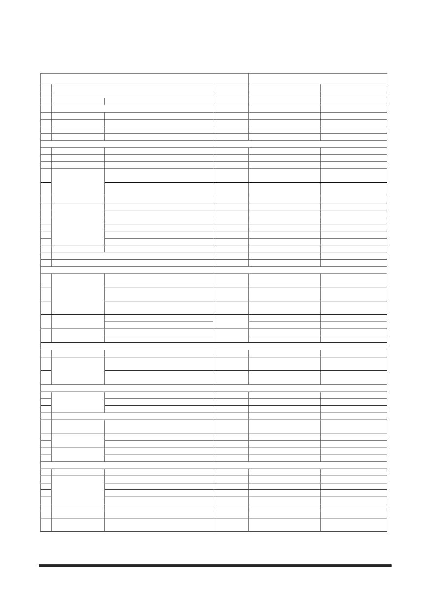
General Section
Specifications
CHARACTERISTICS
TIER-Ⅲ
1
Manufacturer
CROWN
CROWN
2
Model
GC35S-5
GC40S-5
3
Capacity
at rated load center
lb (kg)
7,000 (3,500)
8,000 (4,000)
4
Load center
in (mm)
24 (600)
24 (600)
5
Power type
Elec, Diesel , LPG, Gasoline
LPG
LPG
6
Operator type
Stand-on, Driver-seated
Drider-seated
Drider-seated
7
Tire type
P=Pneu, E=Solid Soft, C=Cushion
C
C
8
Wheels(x=driven)
number, front/rear
x2/2
x2/2
DIMENSIONS
9
Max. Fork Height
with STD 2-Stage Mast
in (mm)
113.4 (2,880)
113.4 (2,880)
10 Free lift
with STD 2-Stage Mast
in (mm)
6.3 (160)
6.3 (160)
11
Fork carriage
ISO class
III
III
47.2x5.9x2.0
47.2x5.9x2.0
12
Length x Width x Thickness
in (mm)
(1,200x150x50)
(1,200x150x50)
Forks
12.2x44.6
12.2x44.6
13
Fork Spacing (min X Max)
in (mm)
(310 x 1,132)
(310 x 1,132)
14
Tilt of mast
Forward/Backward
deg
5/6
5/6
15
Length to Fork Face
in (mm)
105.6 (2,682)
105.7 (2,686)
16
Overall Width
in (mm)
50.0 (1,270)
50.0 (1,270)
17
Mast Lowered Height
in (mm)
84.1 (2,135)
84.1 (2,135)
Overall dimensions
18
Mast Extended Height
in (mm)
162.0 (4,115)
162.0 (4,115)
19
Overhead guard Height
in (mm)
84.8 (2,155)
84.8 (2,155)
20
Seat Height
in (mm)
44.3 (1,125)
44.3 (1,125)
21 Turning radius
Minimum outside
in (mm)
92.9 (2,360)
94.5 (2,400)
22 Load Moment constant
in (mm)
19.9 (505)
19.9 (505)
23
90° Stacking aisle
in (mm)
112.8 (2,865)
114.4 (2,905)
PERFORMANCE
11.2/12.7
11.2/12.7
24
Travel, loaded/unloaded
mhp(km/h)
(18/19)
(18/19)
98.4/108.3
94.5/108.3
25
Speed
Lift, loaded/unloaded
fpm(mm/s)
(500/550)
(480/550)
104.3/88.6
98.4/88.6
26
Lowering, loaded/unloaded
fpm(mm/s)
(530/450)
(500/450)
at 1.0 km/h, loaded
8,488 (3,850)
8,455 (3,835)
27 Drawbar pull
lb (kg)
at 1.6 km/h, loaded
8,025 (3,640)
7,981 (3,620)
at 1.0 km/h, loaded
48
42
28 Gradeability
%
at 1.6 km/h, loaded
44
39
WEIGHT
29
Total weight
Unloaded
lb (kg)
12,060 (5,470)
12,895 (5,850)
16,935/2,125
18,435/2,460
30
with loaded, front/rear
lb (kg)
(7,970/1,000)
(8,690/1,160)
Axle load
4,915/7,145
4,695/8,200
31
without loaded, front/rear
lb (kg)
(2,230/3,240)
(2,130/3,720)
CHASSIS
32
Number of front/rear
2/2
2/2
33
Tires
Size, front single
22x9x16
22x9x16
34
Size, rear
18x6x12-1/8
18x7x12-1/8
35 Wheel base
in (mm)
64.2 (1,630)
64.2 (1,630)
41.0/41.1
41.0/41.1
36
Tread
Front/Rear
in (mm)
(1,042/1,044)
(1,042/1,044)
37
loaded, at the lowest point
in (mm)
5.1 (130)
5.1 (130)
Ground clearance
38
loaded, at center of wheelbase
in (mm)
5.1 (130)
5.1 (130)
39
Service
foot/hyd
foot/hyd
Brake
40
Parking
hand/mech
hand/mech
DRIVE
41 Battery
Voltage/Ampere-hour
V/AH
12/75
12/75
42
Manufacturer/Model
PSI / 4X 4.3L
PSI / 4X 4.3L
43
Rated output (at rpm)
kW/rpm
70.0/2,500
70.0/2,500
Engine
44
Max. torque
lb_ft/rpm
209.4/1,800
209.4/1,800
45
Cycle/Cylinders/Displacement
cc
4/6/4,294
4/6/4,294
46
type
Powershift
Powershift
Transmission
47
No. of Speeds forward/reverse
2/2
2/2
2,755/2,030
3,045/2,030
48
Operating pressure
System/Attachment
psi (bar)
(190/140)
(210/140)
-31-
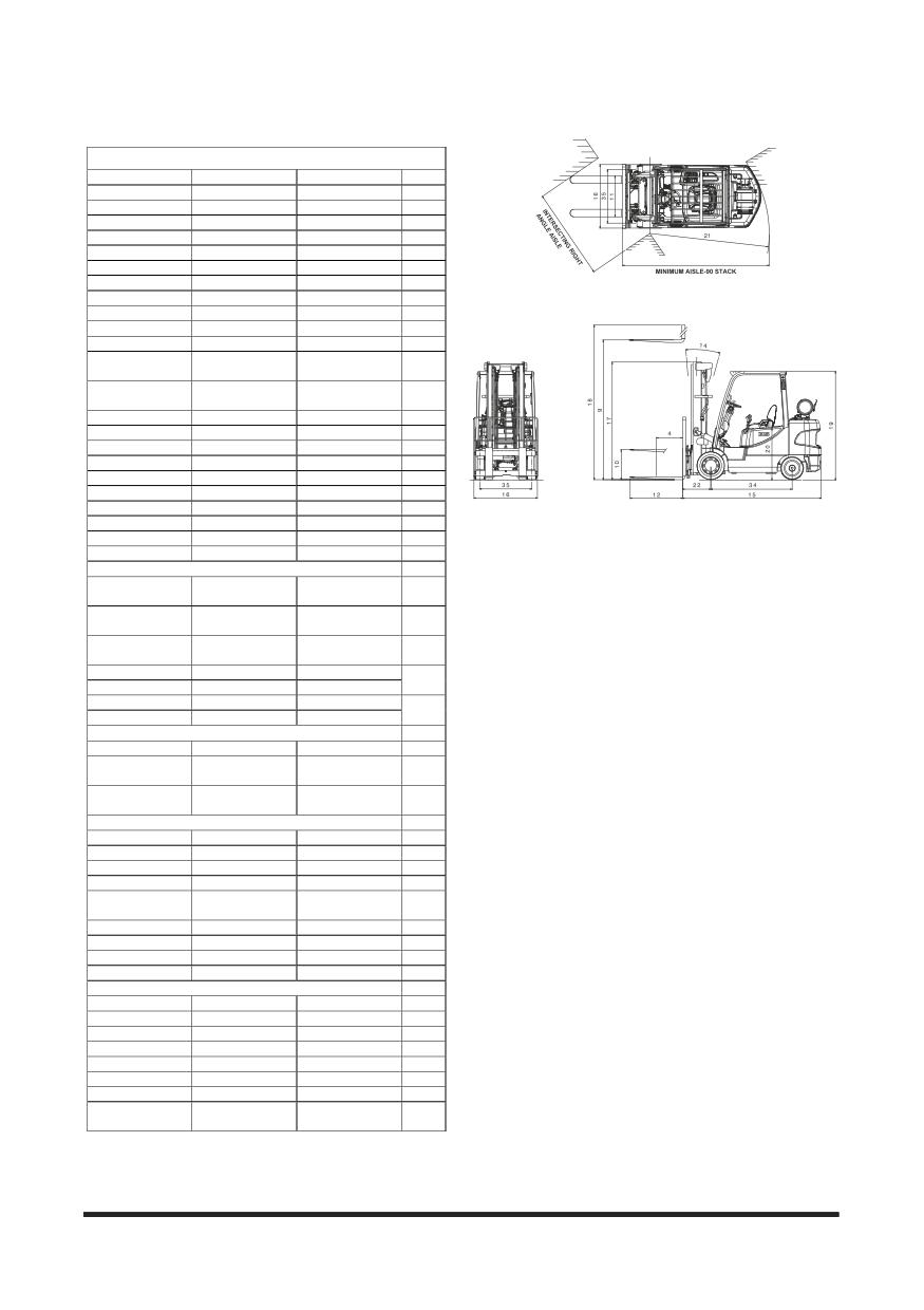
General Section
TIER-Ⅲ
CROWN
CROWN
CROWN
1
GC45S-5
GC50C-5
GC55C-5
2
9,000 (4,500)
10,000(5,000)
12,000 (5,500)
3
24 (600)
24 (600)
24 (600)
4
LPG
LPG
LPG
5
Drider-seated
Drider-seated
Drider-seated
6
C
C
C
7
x2/2
x2/2
x2/2
8
113.4 (2,880)
103.5 (2,630)
103.5 (2,630)
9
6.3 (160)
6.3 (160)
6.3 (160)
10
IV
IV
IV
11
47.2x5.9x2.0
47.2x5.9x2.4
47.2x5.9x2.4
12
(1,200x150x50)
(1,200x150x60)
(1,200x150x60)
13.4x50.8
13.4x50.8
13.4x50.8
13
(340 x 1,290)
(340 x 1,290)
(340 x 1,290)
5/6
5/6
5/6
14
111.3 (2,828)
113.3 (2,878)
118.5 (3,010)
15
55.9 (1,420)
55.9 (1,420)
55.9 (1,420)
16
86.0 (2,185)
86.0 (2,185)
86.0 (2,185)
17
169.9 (4,315)
160.0 (4,065)
160.0 (4,065)
18
84.8 (2,155)
84.8 (2,155)
84.8 (2,155)
19
44.3 (1,125)
44.3 (1,125)
44.3 (1,125)
20
99.6 (2,530)
101.6 (2,580)
103.5 (2,630)
21
19.9 (505)
20.3 (515)
20.3 (515)
22
119.5 (3,035)
121.9 (3,095)
123.8 (3,145)
23
11.2/12.7
11.2/12.7
11.2/12.7
24
(18/19)
(18/19)
(18/19)
94.5/98.4
88.6/98.4
88.6/98.4
25
(480/500)
(450/500)
(450/500)
98.4/86.6
94.5/86.6
94.5/86.6
26
(500/440)
(480/440)
(480/440)
8,466 (3,840)
8,411 (3,815)
8,367 (3,795)
27
8,003 (3,630)
7,937 (2,638)
7,893 (3,580)
37
34
31
28
34
31
29
14,330 (6,500)
15,410 (6,990)
16,180 (7,340)
29
20,730/2,600
22,530/2,880
24,865/3,315
30
(9,775/1,225)
(10,630/1,360)
(11,330/1,510)
5,500/8,830
5,555/9,855
5,290/10,890
31
(2,495/4,005)
(2,520/4,470)
(2,400/4,940)
2/2
2/2
2/2
32
22X12X16
22X12X16
22X12X16
33
18X8X12.1
18X8X12.1
18X8X12.1
34
70.5 (1,790)
70.5 (1,790)
70.5 (1,790)
35
43.9/41.1
43.9/41.1
43.9/41.1
36
(1,116/1,044)
(1,116/1,044)
(1,116/1,044)
5.1 (130)
5.1 (130)
5.1 (130)
37
5.1 (130)
5.1 (130)
5.1 (130)
38
foot/hyd
foot/hyd
foot/hyd
39
hand/mech
hand/mech
hand/mech
40
12/75
12/75
12/75
41
PSI / 4X 4.3L
PSI / 4X 4.3L
PSI / 4X 4.3L
42
70.0/2,500
70.0/2,500
70.0/2,500
43
209.4/1,800
209.4/1,800
209.4/1,800
44
4/6/4,294
4/6/4,294
4/6/4,294
45
Powershift
Powershift
Powershift
46
2/2
2/2
2/2
47
3,045/2,030
3,045/2,030
3,335/2,030
48
(210/140)
(210/140)
(230/140)
-32-
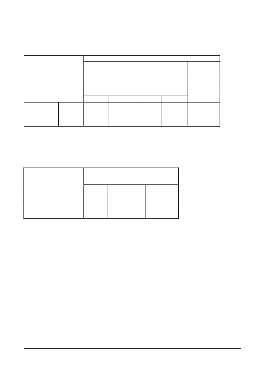
General Section
Noise and Vibration
Noise
Noise Level [Unit : dB(A)]
Sound Pressure Level at
Sound Pressure Level at By-
Guaranteed Sound
Model
Operator’s ear(Leq)
stander position (AS 3713)
Power Level(LWA)
by new directive
2000/14/EC
AS3713
prEN12053
Drive-By
Lifting Mode
CGC35/40/45S-5,
CGC50/55C-5
85.9
-
-
110
(PSI TIER III E/G)
Vibration(weighted overall value)
Unit : m/sec2
Measuring place
Model
Seat
Steering Wheel
Floor Plate
CGC35/40/45S-5, CGC50/55C-5
0.07
1.2
0.09
(PSI TIER III E/G)
-33-
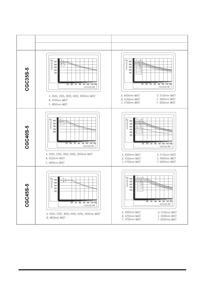
General Section
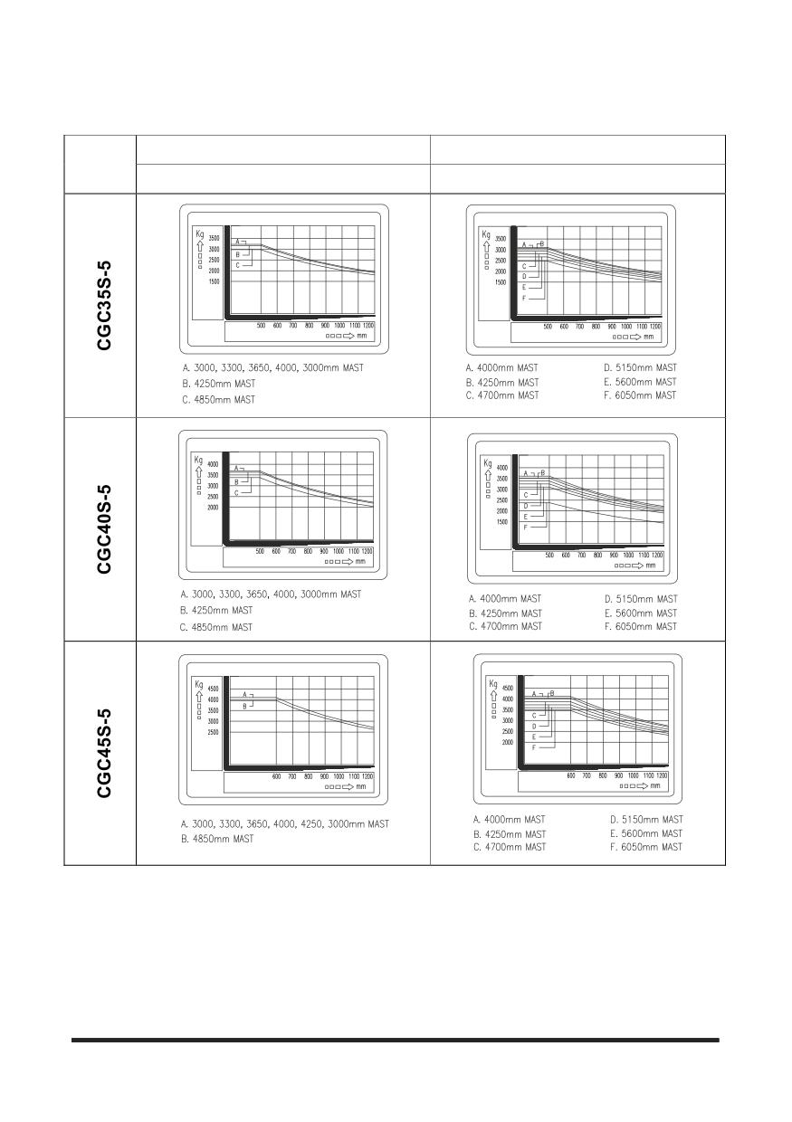
Capacity Chart (Not used in Australia)
SINGLE TYRE
SINGLE TYRE
MODEL
STD, FFL
FFT
-34-
General Section
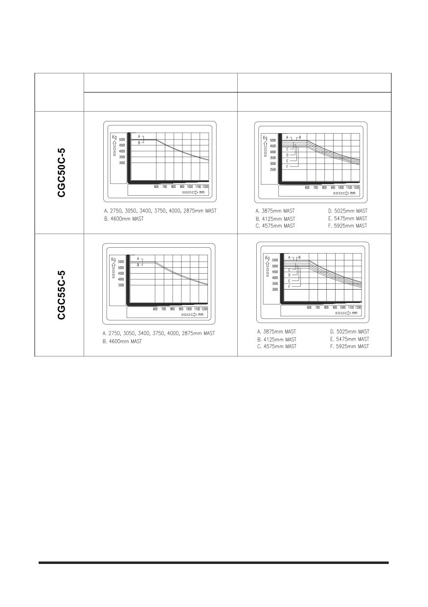
Capacity Chart (with Side Shifter) (Not used in Australia)
SINGLE TYRE
SINGLE TYRE
MODEL
STD, FFL
FFT
-35-
General Section
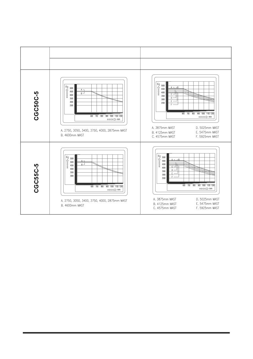
Capacity Chart (Not used in Australia)
SINGLE TYRE
SINGLE TYRE
MODEL
STD, FFL
FFT
-36-
General Section
Capacity Chart (with Side Shifter) (Not used in Australia)
SINGLE TYRE
SINGLE TYRE
MODEL
STD, FFL
FFT
-37-
General Section
Serial Number
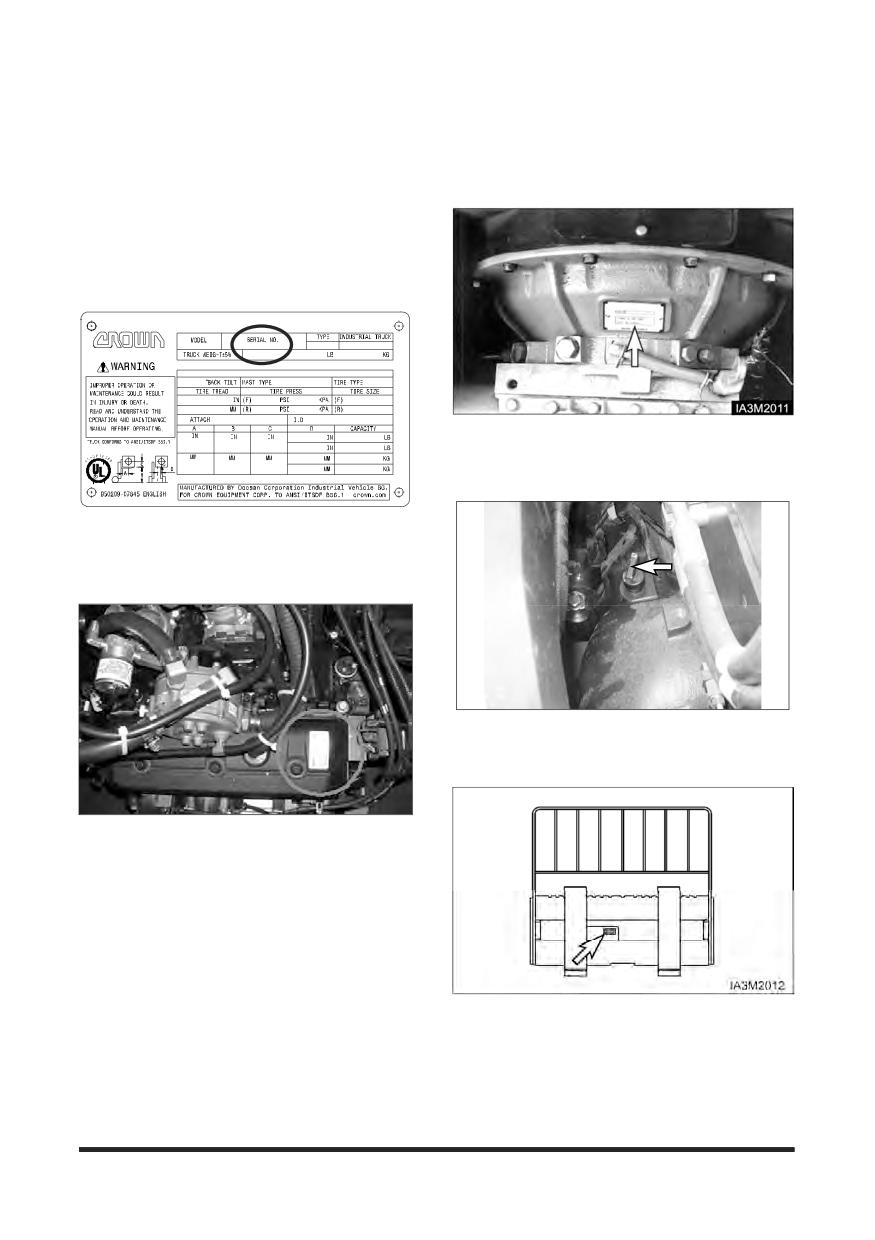
Serial Number Locations
For quick reference, record your lift truck’s serial
numbers in the spaces provided below the
photographs.
Located on the front side of the FCU.
Transmission Serial Number
•______________________________
Lift Truck Serial Number
•______________________________
DRIVE AXLE Serial Number
4.3 liter PSI Engine Serial Number(PSI)
•______________________________
Side Shifter Serial Number(If Equipped)
•______________________________
-38-
General Section
Operator's Warning and Identification Plate
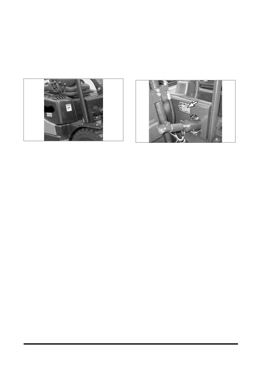
Familiarise yourself with the OPERATOR'S WARNING Plate, and IDENTIFICATION, LIFT CAPACITY and
ATTACHMENT PLATES. Do not exceed capacity as equipped load ratings.
Identification, Lift Capacity and
Operator’s Warning Plate
Attachment Plate
Located on the cowl to the right side of the steering
Located on the front side of the FCU.
column.
Lift Truck Capacity Rating
Do not exceed allowable lift truck working capacity
load ratings.
The capacity of the lift truck is given by weight and
distance to the load centre. For example, a capacity
of 1200kg (2640lb) at 600mm (24in) means that the
lift truck can lift 1200kg (2640lb) if the load centre is
600 mm (24in) from both the vertical and horizontal
faces of the forks.
Before attempting to lift any load, ensure that the
weight and load centre combination is within the
capacity of the lift truck as shown on the capacity
rating plate. To determine the load centre, measure
the distance from the face of the carriage to the
gravitational centre of the load.
The rated capacity on the plate refers to the capacity
of the lift truck as it left the factory. Subsequent
changes of any form to the equipment or battery can
alter the lift truck’s rating.
The rated capacity of the lift truck applies to
operating conditions where the lift truck is on level
ground. The capacity of the lift truck is reduced on
inclines.
Below are abbreviations that may appear on the
Identification, Lift Capacity and Attachment Plate
and their meanings.
-39-
General Section
Mast Abbreviations
Attachment Abbreviations (Includes
Special Forks)
STD - Standard Mast (single inner member, low free lift)
SC - Special Carriage-increased width, height or
FF - Full Free Lift Mast (single inner member with high
outreach
free lift duplex cylinder)
SSS - Shaft-type Sideshift Carriage
FFT - Triple Lift Mast (two inner members) with either
low or full free lift characteristics.
HSS - Hook-type Sideshift Carriage (ITA)
QUAD - Quadruple (Quad) Mast (with three inner
CW - Counterweight
members)
SF - Special Forks
NOTE : When only a mast-type is listed on the
identification plate, a standard carriage
SWS - Swing Shift, Sideshift
and forks are used.
RAM - Ram or Boom
DBCBH - Double Cube Block Handler
HFP - Hydraulic Fork Positioner
CR - Crane Arm or Crane Boom
TH - Tyre Handler
CTH - Container Handler
LPP - Load Push-Pull Device
CC - Carton Clamp
RC - Roll Clamp
LS - Load Stabiliser
PWH - Pulp Wood Handler
SS-ST - Sideshift-Side Tilt Carriage
-40-
Operation Section
Operator’s Station and Monitoring Systems
Instrument Panel
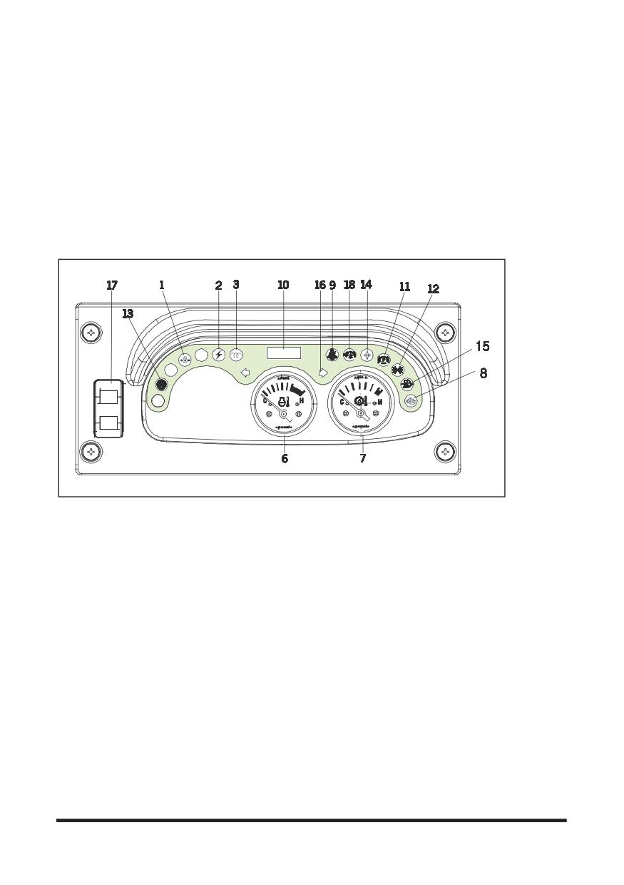
Your lift truck may not have the same indicator or warning lights as shown in the illustrations.
Due to the various options available, typical instrument panels are shown.
However, the symbols on the indicators and lights on your panel identify what those particular items are.
Also, the symbol for each of the items is identified and an explanation of their function and location is
described on the following pages.
LPG (12V)
-41-
Operation Section
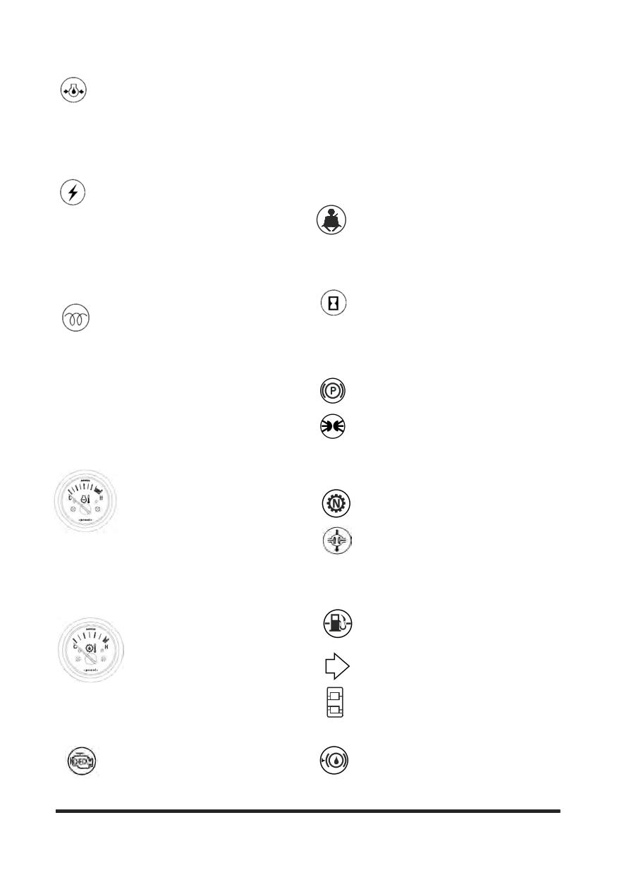
1. Engine Oil Pressure Indicator Light -
(MIL) as Diagnostic Faults Codes (DFC) or flash
Indicates insufficient engine oil pressure.
codes, and viewed in detail with the use of service
The light will come on when the ignition
tool software. When the ignition key is turned ON
switch is turned to the ON position. The light should
the MIL will perform a self-test, illuminate once and
go off after the engine is started. If the light turns on
then go OFF. If a detected fault condition exists, the
while operating the lift trucks, insufficient engine oil
fault or faults will be stored in the memory of the
pressure is indicated. Park the lift truck and stop the
engine control module (ECM). Once a fault occurs
engine.
the MIL will illuminate and remain ON. This signals
the operator that a faults has been detected by the
2. Alternator Indicator Light - Indicates if
SECM.
the battery charging system is operational.
The light will come on when the ignition
9. Seat Belt Warning Light (If Equipment) -
switch is turned to the ON position.
Indicates when the seat belt does not
fastened by operator.
The light should go off after the engine is started,
indicating the alternator is producing sufficient
The light will come on when the ignition switch is
voltage to charge the battery. If the light turns on
turned to the on position. The light should go off
with the engine running, check the alternator
after engine is started.
charging system for a malfunction.
10. Service Hour Meter - Indicates the total
3. Diesel Engine Start Preheat Indicator
number of hours the engine and the lift truck
Light - The light will come ON when the
have operated. The hour meter will operate
key is turned to the ON position from the
when the ignition switch is in the ON position,
OFF position. This indicates that the glow plugs are
whether the engine is running or not. The hour
preheating the pre-combustion chambers for easier
meter is used to determine lubrication and
starting.
maintenance intervals.
The amount of time needed to preheat the pre-
11. Parking indicator light- The light will come
combustion chambers is approximately seven
ON when the parking lever is applied.
seconds, depending on the surrounding air
temperature. When the light goes OFF the
12. Front Floodlights- Push down on the
maximum pre-combustion chamber temperature has
switch(17), to the first step, to turn the front
been reached and the key can be turned to the
floodlights on.
START position to start the engine.
Front and Rear Floodlights - Push down on the
switch(17), to the second step, to turn both the front and
6. Engine Coolant Temperature
rear floodlights on. The floodlights are optional.
Gauge - Shows current temperature
of the engine coolant. If the gauge
13. Transmission Neutral Position Light -
pointer moves beyond the red band
Indicates the neutral position of transmission.
during the operation, the engine is
overheated. Park the lift truck and
14. Drive Axle Oil Indicator Light (OCDB
stop the engine.
only) - Indicates too hot drive axle oil.
The light will be ON when the ignition switch is
Check the cooling system for any defect. The
in the ON position and must go OFF when the engine is
pointer will be in the red band when the coolant
running.
temperature reaches approximately 110 °C on all
Do not continue to operate the lift truck if the light is
engines.
ON during operation.
7. Transmission Oil Temperature
15. Low Level Light of LP GAS
-
Gauge - Shows transmission oil
temperature If the gauge pointer
Indicates the low Level of LP GAS (LP
moves beyond the red band during
only) (If Equipped)
operation, the engine is overheated.
Park the lift truck and stop the
16. Directional Turning Indicator Light
engine.
17. Front and Rear Floodlishts Switch -
Check the system for any defect. The pointer will be
The front floodright is ON when push down
in the red band when the transmission oil
switch to the first step. The front and rear
temperature reaches approximately 125 °C.
floodlights are ON when push down switch to
the second step.
8. PSI Engine Malfunction Indicator
Lamp (MIL) -PSI engine control system
18. Brake Fluid Oil Light (If Equipped) -
The light is ON when the brake fluid oil of
are equipped with built-in fault
brake reservoir comes down to low level
diagnostics. Detected system faults can
position. Refill the proper brake fluid oil if its
be displayed by the Malfunction Indicator Lamp
light is ON.
-42-
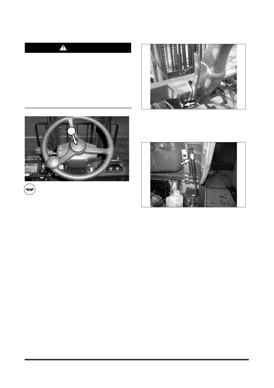
Operation Section
Engine Compartment
WARNING
Frequent rapid starts at 2nd speed can be the
cause of overheating at torque converter. With
this operating condition, the pointer can
sometimes exceed the green band. If this
situation occurs from time to time, please avoid
this operating condition to protect the
transmission and increase the work efficiency.
That is, start the truck at 1st speed and shift to
2nd speed to increase the travel speed.
1. The engine compartment is accessible by pulling
the latch and raising the hood and seat assembly.
NOTE: Unlock latch before pulling if key equipped.
19
19. Horn Switch - Push on the horn button
to sound the horn.
2. The hood and seat assembly is held up by a
support cylinder. Make certain the air cylinder is
operating properly and securely holds the hood up
before doing anything in the engine compartment.
-43-
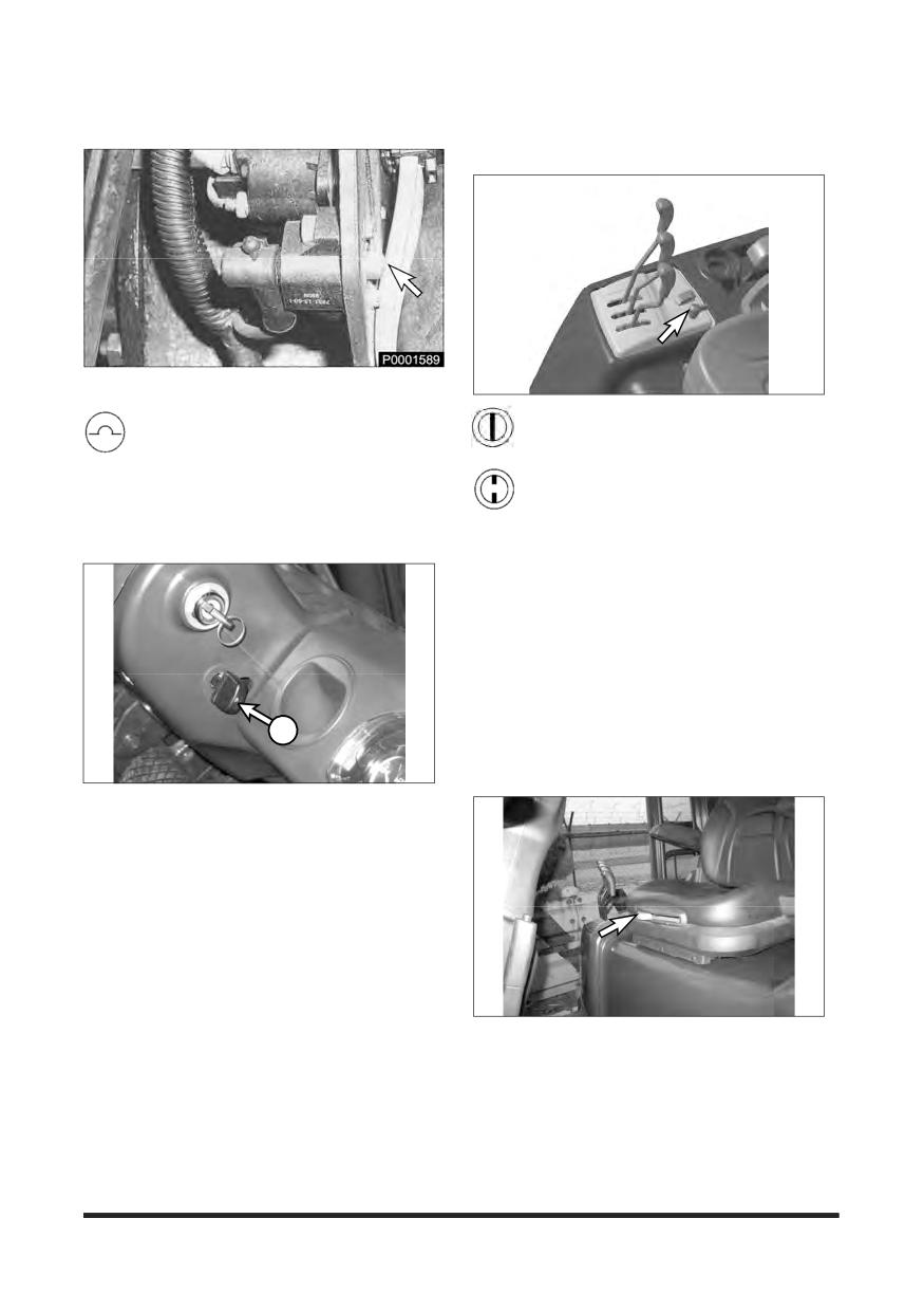
Operation Section
Circuit Breaker
Electrical Disconnect Switch (If E
quipped)
Typical Example
LP Engine Truck
Circuit Breaker
- Protects the main
1. ON-Connects the battery for electrical
electrical circuits. To reset the circuit
power to all electrical circuits.
breaker, push the button in. Located in the
engine compartment.
2. OFF-Disconnects the battery from all
electrical circuits.
Tilt Steering Column
Seat
NOTE: Seat arrangements may vary. Basic
operation will be similar.
Seat adjustment should be checked at the beginning
of each shift and when operators change.
Lock the seat into position before operating, to
prevent an unexpected seat change.
1
Adjust seat to allow full brake pedal travel with
operator’s back against seat back.
To adjust the steering column, push down the kn
ob(1), and move the steering column to the desir
ed position, then release the knob(1).
NOTE: The seat can only be correctly adjusted
with the operator fully seated.
-44-
Operation Section
Seat Switch System (If Equipped)
NOTICE
Prior to operating the lift truck, be sure to
understand and check the SEAT SWITCH SYSTEM.
While in normal operation and on level ground,
select a direction with the directional lever and with
the park brake released. You will note that the truck
will move slowly in the selected direction. If you lift
yours hips off of the seat, within three seconds, the
SEAT SWITCH SYSTEM will desengage the
transmission allowing the truck to coast but not
automatically stop.
To restore the lift truck to normal operation, while
sitting in the operator's seat depress the brake pedal
The lift truck is equipped with a SEAT SWITCH
to hold the lift truck, return the directional lever to the
SYSTEM. In normal operation if the direction lever is
neutral position, and then reselect a direction of
placed in either forward or reverse, the lift truck will
travel (either forward or reverse). The transmission
move at a speed proportional to the accelerator
will then re-engage.
pedal's position. If the operator leavers the seat
without setting the parking brake, within three
If seat or seat switch replacement becomes
seconds after leaving the seat, the SEAT SWITCH
necessary, be sure to use genuine CROWN lift truck
SYSTEM will automatically disengage the
parts. Lift trucks should never be operated without
transmission. The directional lever, however, will
an operational SEAT SWITCH SYSTEM.
remain in that forward or reverse location although
internally the transmission will have shifted into
neutral.
Before exiting the lift truck, the parking brake should
always be applied.
WARNING
WHEN LEAVING MACHINE APPLY PARKING
BRAKE!
PARKING BRAKE IS NOT AUTOMATICALLY
APPLIED.
NOTE: Some trucks may be equipped (ask your
dealer if this applies to your truck) with an
alarm that will sound if the parking brake is
not applied when leaving the machine.
-45-
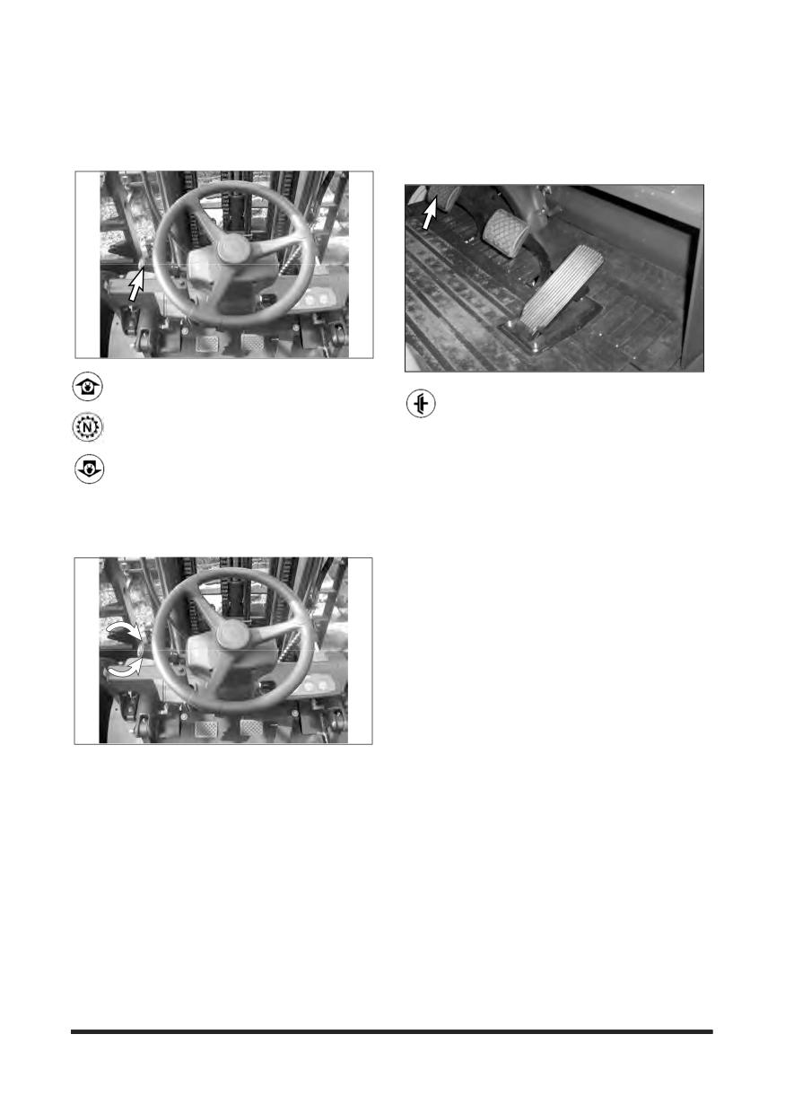
Operation Section
Lift Truck Controls
Direction Control Lever
Transmission Inching Control
Pedal
1. Forward - Push the lever forward for
FORWARD direction travel.
Inching Control Pedal - Pushing down on
the inching pedal, modulates the hydraulic
2. Neutral - Move the lever to centre position
pressure to the clutch packs, permitting disc
for NEUTRAL.
slippage.
3. Reverse
- Pull the lever back for
Further pushing on the pedal completely relieves
REVERSE direction travel.
clutch pack pressure and applies the service brakes
to stop and hold the lift truck.
NOTE: The purpose of the inching control pedal is
Transmission Speed Range Lever
to provide precise inching control at slow
travel speed, with high engine rpm. This is
used for fast hydraulic lift during load
approach, pickup or positioning.
1. High - Rotate the lever counterclockwise for
HIGH speed range.
2. Low - Rotate the lever clockwise for LOW speed
range.
-46-
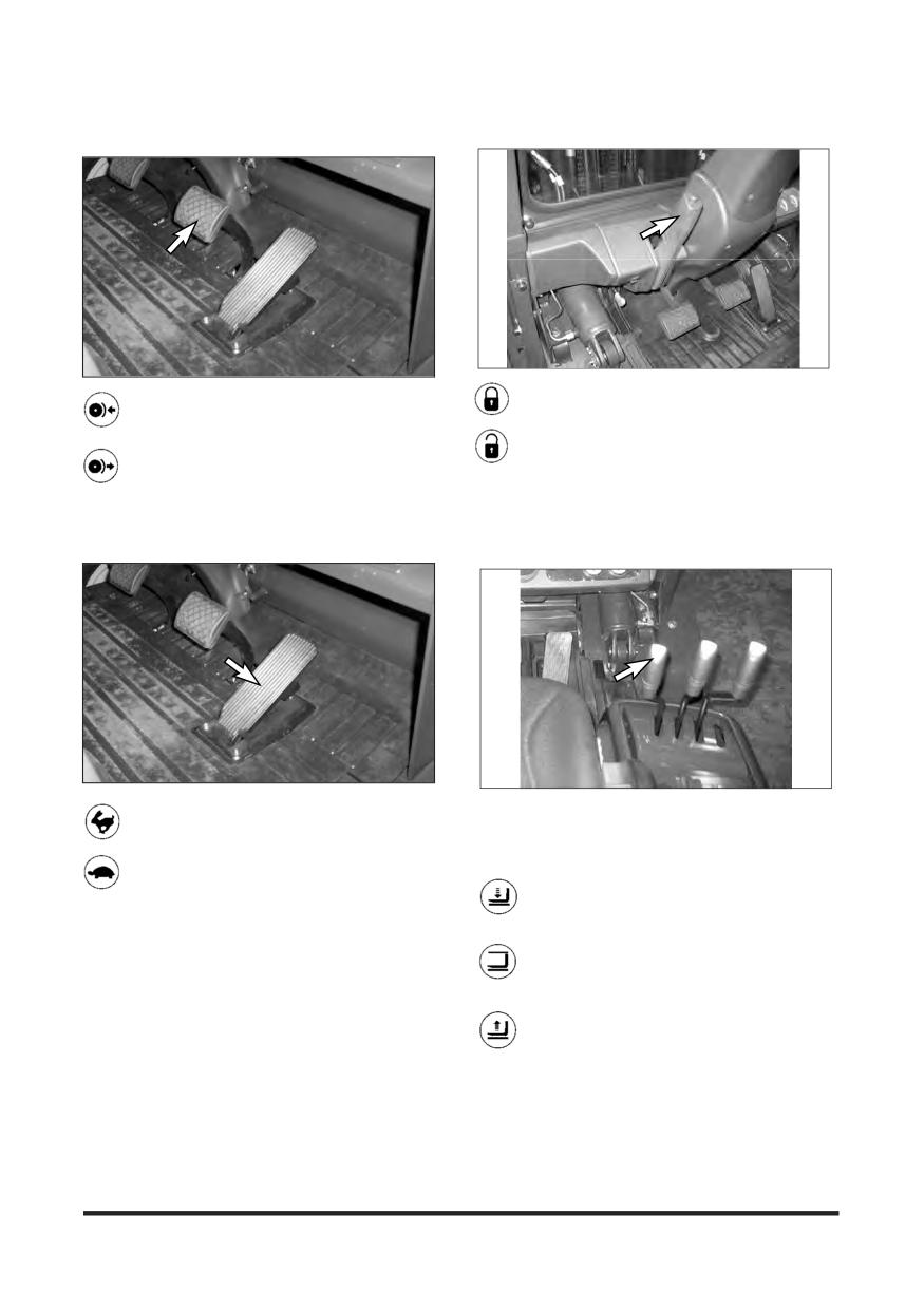
Operation Section
Parking Brake Lever
Service Brake Pedal
Pull the lever BACK to engage the parking
Push DOWN on the brake pedal to slow or
stop the lift truck.
brake.
RELEASE the brake pedal to allow the lift
Push the lever FORWARD to release the
truck to move.
parking brake.
Accelerator Pedal
Lift Control
Push DOWN on the pedal to increase
NOTE: To prevent a sudden change of position of
engine rpm (speed).
the load, operate all lift, tilt and attachment
controls smoothly.
RELEASE the pedal to decrease engine rpm
(speed).
1. Lower Position
- Push the lever
FORWARD smoothly to lower the load.
2. Hold Position
- When the lever is
released it will return to the HOLD or centre
position. Lifting or lowering action will stop.
3. Lift Position - Pull the lever BACK
smoothly to lift the load.
-47-
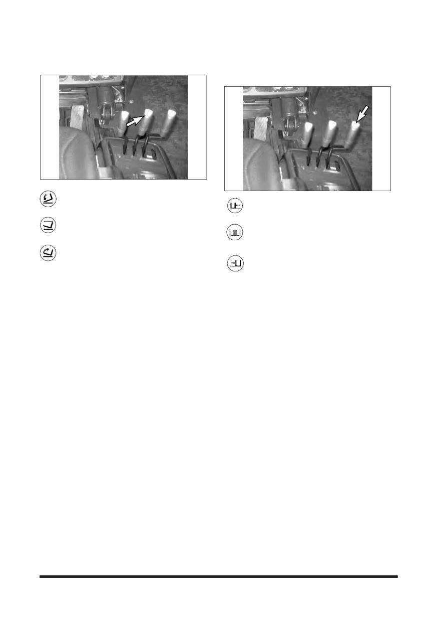
Operation Section
Sideshift Attachment Control (If
Tilt Control
Equipped)
1. Mast Tilt Forward
- Push the lever
FORWARD smoothly to tilt the mast forward.
1. Sideshift Left
- Push the lever
FORWARD to shift the carriage to the left.
2. Mast Hold - When the lever is released it
will return to the HOLD or centre position.
2. Sideshift Hold
- When the lever is
Tilting action will stop.
released it will return to the HOLD or centre
position. Sideshifting action will stop.
3. Mast Tilt Back - Pull the lever BACK
smoothly to tilt the mast backward.
3. Sideshift Right - Pull the lever BACK to
shift the carriage to the right.
-48-
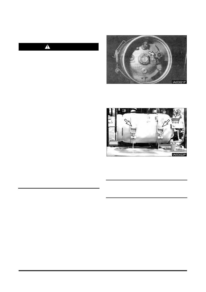
Operation Section
Refueling
Changing LP Tanks
WARNING
Only trained, authorised personnel should fill or
exchange LP tanks.
Personnel engaged in filling of LP containers
should wear protective clothing such as face
shield, long sleeves and gauntlet gloves.
Do not refuel or store LP powered lift trucks near
any underground entrance, elevator shafts or
any other place where LP could collect in a
2.
Close the fuel inlet valve at the LP tank. Run the
pocket causing a potentially dangerous
condition.
engine until it stops, then turn off the ignition switch
and the electrical disconnect switch (if equipped).
Examine all LP containers before filling and
3.
Disconnect the fuel supply line.
again before reuse, for damage to various valves,
liquid gauge, fittings and hand valve wheels.
All defective or damaged LP containers must be
removed from service.
Explosive fumes may be present during
refueling.
Do not smoke in refueling areas.
Lift truck should be refueled only at designated
safe locations. Safe outdoor locations are
preferable to indoor locations.
Stop the engine and get off the lift truck during
refueling.
4.
Loosen the retaining clamps and remove the tank.
The careless handling of LP containers can
5.
Check the mounting to be sure the locating pin
result in a serious accident.
(dowel) is not missing or broken.
Use extreme care when transporting containers
to prevent damage to them.
NOTICE
If the location pin (dowel) is missing or broken, be
1. Park the lift truck on level ground, with the parking
sure the pin is replaced.
brake applied, the transmission in NEUTRAL, the
forks lowered and the engine running at low idle.
-49-
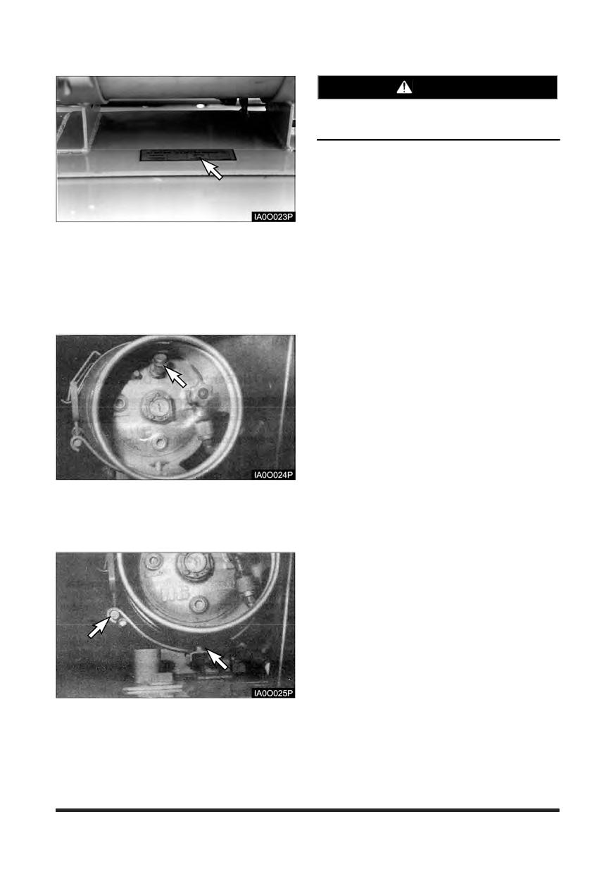
Operation Section
WARNING
The LP tank must not extend past the
counterweight.
12. Clamp the tank securely.
13. Connect the fuel supply line.
14. Open the fuel valve by slowly turning the valve
counterclockwise. If the fuel valve is opened too
quickly, a back pressure check valve will shut off the
fuel supply. If this happens, close the fuel valve
completely. Wait five seconds and then open the
6. Check to be sure that the LP warning plate is in
fuel valve very slowly.
position on the lift truck, and is legible.
15. Inspect the LP fuel lines and fittings with a soap
7. Check to be sure the replacement tank is of the
solution after filling the tank or when looking for
correct type.
leaks.
8. Inspect the replacement tank for damage such as
dents, scrapes or gouges and for indication of
leakage at valves or threaded connections.
9. Check for debris in the relief valve, for damage to
various valves and liquid level gauge.
10. Inspect the quick-disconnect couplings for
deterioration, damage or missing flexible seals.
11. Position the replacement tank so that the locating
pin (dowel) is in place.
-50-
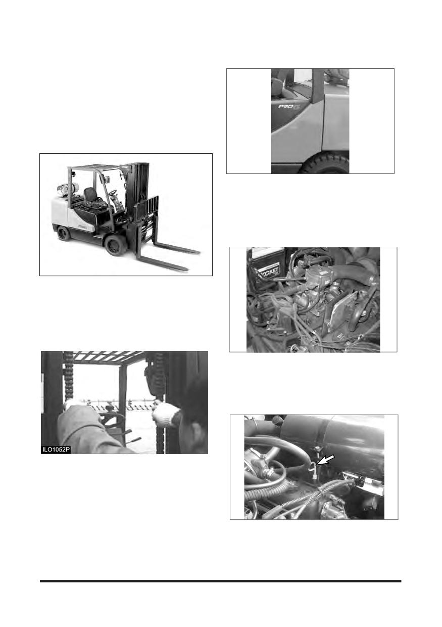
Operation Section
Before Starting the Engine
Walk - Around Inspection
Make a thorough walk-around inspection before
mounting the lift truck or starting the engine. Look
for such items as loose bolts, debris buildup, oil or
coolant leaks. Check condition of tyres, mast,
carriage, forks or attachments. Have repairs made
as needed and all debris removed.
7. Inspect the overhead guard and cabin for damage
and loose or missing mounting bolts.
8. Inspect the hydraulic system for leaks, worn hoses
or damaged lines.
9. Look for transmission and drive axle leaks on the lift
truck and on the ground.
1. Inspect the operator's compartment for loose items
and cleanliness.
2. Inspect the instrument panel for broken or damaged
indicator lights or gauges.
3. Test the horn and other safety devices for proper
operation.
Typical Example
LP Engine Truck
10. Inspect the engine compartment for oil, coolant and
fuel leaks.
11. Inspect common parts and drive axle, mast etc for
grounded, loosen or missing mounting bolts.
4. Inspect the mast and lift chains for wear, broken
links, pins and loose rollers.
5. Inspect the carriage, forks or attachments for wear,
damage and loose or missing bolts.
6. Inspect the tyres and wheels for cuts, gouges,
foreign objects, inflation pressure and loose or
missing bolts.
12. Measure the engine crankcase oil level with the dip
stick. Maintain the oil level between the MAX. and
MIN., (or FULL and ADD) notches on the dip stick.
-51-
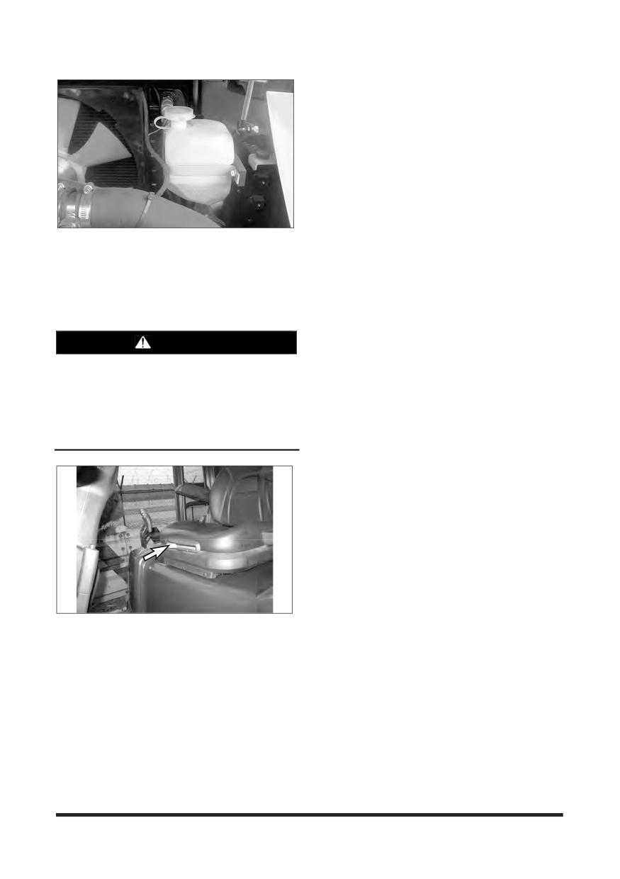
Operation Section
13. Observe the engine coolant level in the coolant
recovery bottle. With the engine cold, maintain the
level to the COLD mark. If the recovery bottle is
empty, also fill the radiator at the top tank.
14. In case of LPG truck, if needed, change LPG Fuel
Tank as the procedure of changing LP tanks in
Refueling Section.
WARNING
Personal injury may occur from accidents
caused by improper seat adjustment. Always
adjust the operator's seat before starting the lift
truck engine.
Seat adjustment must be done at the beginning
of each shift and when operators change.
15. To position the seat, PUSH the lever away from the
seat track and move the seat forward or backward
to a comfortable position.
-52-
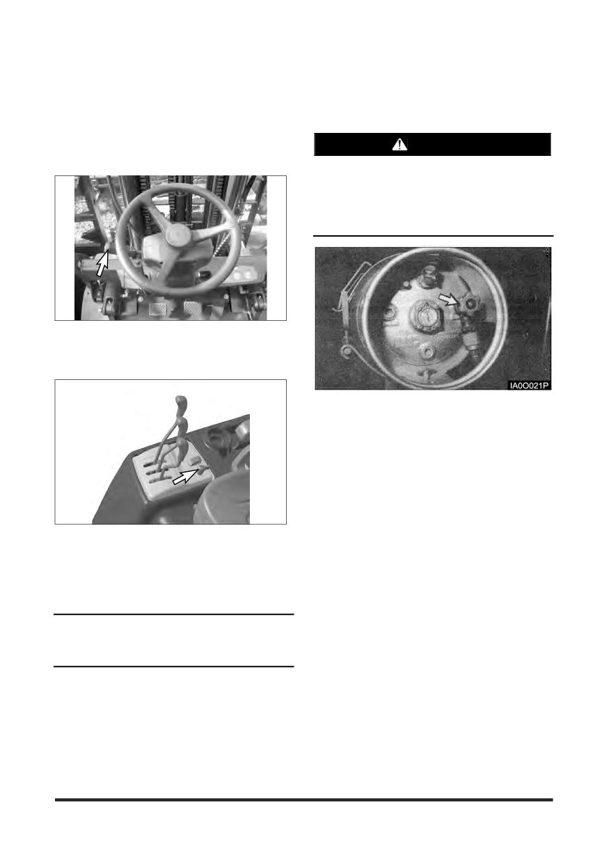
Operation Section
Starting the Engine
Prestart Conditions
LP Engine
NOTE: The engine will not start unless the
WARNING
transmission directional control lever is in
the NEUTRAL position.
LP fuel is flammable and can cause personal
injury.
Inspect LP fuel lines and fitting for leaks.
Inspect tank for secure mounting.
1. Engage the parking brake, if not already engaged.
Place the transmission directional control lever in the
NEUTRAL position.
1. Open the tank fuel valve by slowly turning the valve
counterclockwise. Observe the LP gauge(if
equipped).
2. Turn the engine ignition switch to the START
position. Release it when the engine starts.
3. If the engine does not start, do not press on the
accelerator pedal. Turn the starter switch to OFF
position, then repeat step 2 and depress the
accelerator pedal slightly during cranking.
4. Allow the engine to warm up slowly.
2. If Lift trucks are equipped with electrical disconnect
switches, the engine will not start unless the
disconnect switch is in the ON (closed) position.
Before starting, turn the disconnect switch to the
OFF(open) position.
NOTICE
When you restart the engine after turning off it, wait
4 to 5 seconds and restart it to protect the starter.
-53-
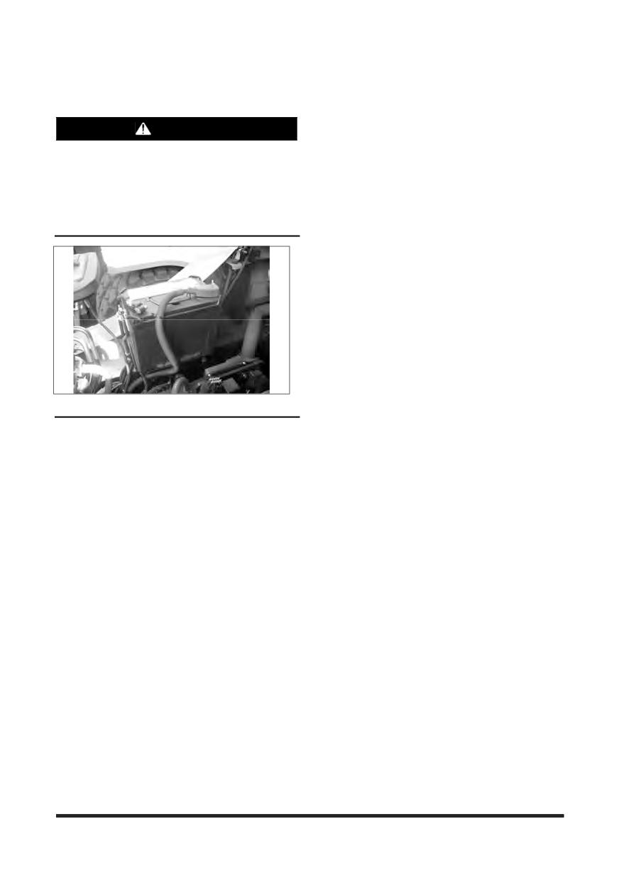
Operation Section
Starting From a 12 Volt External
Source
WARNING
Sparks occurring near the battery could cause
vapors to explode.
Always connect the external power source
ground cable to a point away from and below the
battery, and well clear of fuel system
components.
NOTICE
Do not reverse battery cables. It can cause damage
to the alternator.
Always connect the external power source cables in
parallel with the lift truck battery cables
:
POSITIVE(+) to POSITIVE(+) and NEGATIVE(-) to
NEGATIVE(-).
Attach ground cable last, remove first. All lift trucks
equipped with CROWN built internal combustion
engines are NEGATIVE(-) ground
-54-
Operation Section
Electronic Controlled Spark-Ignition Engines
PSI 4.3L LP Engine
The primary components of the fuel system are the fuel supply, direct electronic pressure regulator (DEPR),
fuel mixer, electronic throttle control (ETC) device, 2-Stage convertor, engine control module (ECM), and a
catalytic converter. The system operates on a slightly positive fuel pressure. Primary fuel pressure can be
measured at the LD 2-Stage convertor. Secondary fuel pressure command and actual fuel pressure is
monitored by the ECM.
To obtain maximum effect from the catalyst and accurate control of the air fuel ratio, the emission certified
engine is equipped with an onboard computer or Engine Control Module (ECM). The ECM is a 32 bit
controller which receives input data from sensors mounted to the engine and fuel system and then outputs
various signals to control engine operation.
One specific function of the controller is to maintain a closed loop fuel control which is accomplished by use of
the Heated Exhaust Gas Oxygen sensor (HEGO) mounted in the exhaust system. The HEGO sensor sends a
voltage signal to the controller which then outputs signals to the EPR to change the amount of fuel being
delivered from the regulator or mixer to the engine.
The controller also performs diagnostic functions on the fuel system and notifies the operator of engine
malfunctions by turning on a Malfunction Indicator Light (MIL) mounted in the dash. Malfunctions in the
system are identified by a Diagnostic Trouble Code (DTC) number. In addition to notifying the operator of the
malfunction in the system, the controller also stores the information about the malfunction in its memory. A
technician can than utilize a computerized diagnostic scan tool to retrieve the stored diagnostic code and by
using the diagnostic charts in this manual to determine the cause of the malfunction. In the event a technician
does not have the computerized diagnostic tool, the MIL light can be used to identify the diagnostic code to
activate the “blink” feature and count the number of blinks to determine the diagnostic code number to locate
the fault in the system.
The primary components of the Gasoline Multi Point Fuel Injection (MPFI) fuel system are the gasoline fuel
tank, electric fuel pump, fuel pressure and temperature sensor manifold, fuel filter and fuel rail.
This engine is equipped with a fuel injector rail that does not have a pressure regulator or a return circuit to
the fuel tank. Fuel pressure for this engine is regulated by the engine’s ECM. The ECM receives fuel
pressure and temperature feedback from the gasoline fuel sensor manifold and uses this information to
control the ground side of the fuel pump. Fuel pressure is regulated by the ECM pulse width modulating
(PWM) the fuel pump. The fuel pressure and temperature sensor manifold has a return or “bleed” circuit that
connects back to the equipment fuel tank. This circuit is used to bleed off any vapor that develops in the line
and returns a small amount of fuel to the tank. The fuel comes from the fuel tank and passes through the fuel
pump. Fuel exits the fuel pump, passes through the filter and then enters the fuel pressure and temperature
manifold assembly. Fuel flows through the feed circuit and is delivered to the fuel injector rail. Fuel that enters
the bleed circuits through the by-pass valve in the manifold is returned to the fuel tank.
-55-
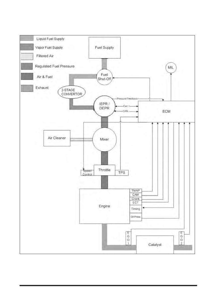
Operation Section
EMS schematic of PSI 4.3L LP engine
-56-
Operation Section
Basic Troubleshooting(LP)
The PSI 4.3L fuel systems are equipped with built-in fault diagnostics. Detected system faults can be
displayed by the Malfunction Indicator Lamp (MIL) and are covered in the Advanced Diagnostics section.
Items such as fuel level, plugged fuel lines, clogged fuel filters and malfunctioning pressure regulators may
not set a fault code by the Engine Control Module (ECM).
Below are basic checks that should be made before referring to the Advanced Diagnostics section, if engine
or drivability problems are encountered.
Locating a problem in a propane engine is done exactly the same way as with a gasoline engine.
Consider all parts of the ignition and mechanical systems as well as the fuel system.
FUEL SYSTEM SYMPTOM DIAGNOSTICS
Checks
Action
Before using this section, you should have performed On Board Diagnostic (OBD)
Check and determined that:
1. The ECM and MIL are operating correctly.
Before Using
2. There are no Diagnostic Trouble Codes (DTCs) stored, or a DTC exists but
This Section
without a MIL.
Several of the following symptom procedures call for a careful visual and physical
check. These checks are very important as they can lead to prompt diagnosis and
correction of a problem.
1. Verify the customer complaint.
2. Locate the correct symptom table.
3. Check the items indicated under that symptom.
4. Operate the equipment under the conditions the symptom occurs. Verify HEGO
Fuel System Check
switching between lean and rich. IMPORTANT! Normal HEGO switching
indicates the fuel system is in closed loop and operating correctly at that
time.
5. Take a data snapshot using the DST under the condition that the symptom
occurs to review at a later time.
• Check all ECM system fuses and circuit breakers.
• Check the ECM ground for being clean, tight and in its proper location.
• Check the vacuum hoses for splits, kinks and proper connections.
• Check thoroughly for any type of leak or restriction.
• Check for air leaks at all the mounting areas of the intake manifold sealing
surfaces.
• Check for proper installation of the mixer assembly.
• Check for air leaks at the mixer assembly.
Check the ignition wires for the following conditions:
Visual and Physical
• Cracking
Checks
• Hardening
• Proper routing
• Carbon tracking.
Check the wiring for the following items: proper connections, pinches or cuts.
The following symptom tables contain groups of possible causes for each symptom.
The order of these procedures is not important. If the DST readings do not indicate a
problem, then proceed in a logical order, easiest to check or most likely to cause the
problem.
-57-
Operation Section
INTERMITTENT
Checks
Action
DEFINITION: The problem may or may not turn ON the (MIL) or store a Diagnostic Trouble Code (DTC).
Do not use the DTC tables. If a fault is an intermittent, the use of the DTC tables
Preliminary Checks
with this condition may result in the replacement of good parts.
Faulty electrical connections or wiring can cause most intermittent problems.
Check the suspected circuit for the following conditions:
• Faulty fuse or circuit breaker, connectors poorly mated, terminals not fully seated
in the connector (backed out). Terminals not properly formed or damaged.
• Wire terminals poorly connected.
Faulty Electrical
• Terminal tension is insufficient.
Connections
• Carefully remove all the connector terminals in the problem circuit in order to
or Wiring
ensure the proper contact tension.
• If necessary, replace all the connector terminals in the problem circuit in order to
ensure the proper contact tension (except those noted as “Not Serviceable”). See
section Wiring Schematics.
• Checking for poor terminal to wire connections requires removing the terminal
from the connector body.
If a visual and physical check does not locate the cause of the problem, operate the
Operational Test
vehicle with the DST connected. When the problem occurs, an abnormal voltage or
scan reading indicates a problem circuit.
The following components can cause intermittent MIL and no DTC(s):
• A defective relay.
• Switch that can cause electrical system interference. Normally, the problem will
Intermittent MIL
occur when the faulty component is operating.
Illumination
• The improper installation of add on electrical devices, such as lights, 2-way
radios, electric motors, etc.
• The ignition secondary voltage shorted to a ground.
• The MIL circuit or the Diagnostic Test Terminal intermittently shorted to ground.
• The MIL wire grounds.
To check for the loss of the DTC Memory:
1. Disconnect the TMAP sensor.
Loss of DTC
2. Idle the engine until the MIL illuminates.
Memory
3. The ECM should store a TMAP DTC which should remain in the memory when
the ignition is turned OFF. If the TMAP DTC does not store and remain, the ECM
is faulty.
-58-
Operation Section
NO START
Checks
Action
DEFINITION: The engine cranks OK but does not start.
Preliminary Checks
None
Use the DST to :
• Check for proper communication with both the ECM
ECM Checks
• Check all system fuses engine fuse holder. Refer to Engine Controls Schematics.
• Check battery power, ignition power and ground circuits to the ECM. Refer to
Engine Control Schematics. Verify voltage and/or continuity for each.
• Check the TMAP sensor.
Sensor Checks
• Check the cam angle sensor for output (RPM).
Important: A closed LPG manual fuel shut off valve will create a no start condition.
• Check for air intake system leakage between the mixer and the throttle body.
Fuel System
Verify proper operation of the low pressure lock-off solenoids.
Checks
• Verify proper operation of the fuel control solenoids.
• Check the fuel system pressures.
• Refer to the LPG Fuel System Diagnosis.
• Check for proper mixer air valve operation.
Note: LPG being a gaseous fuel requires higher secondary ignition system voltages
for the equivalent gasoline operating conditions.
1. Check for the proper ignition voltage output with J 26792 or the equivalent.
2. Verify that the spark plugs are correct for use with LPG.
Check the spark plugs for the following conditions:
Ignition System
• Wet plugs.
Checks
• Cracks.
• Wear.
• Improper gap.
• Burned electrodes.
• Heavy deposits.
• Check for bare or shorted ignition wires.
• Check for loose ignition coil connections at the coil.
-59-
Operation Section
NO START
Checks
Action
Important: The LPG Fuel system is more sensitive to intake manifold leakage than
the gasoline fuel system.
Check for the following:
• Vacuum leaks.
Engine Mechanical
• Improper valve timing.
Checks
• Low compression.
• Improper valve clearance.
• Worn rocker arms.
• Broken or weak valve springs.
Worn camshaft lobes.
Check the exhaust system for a possible restriction:
Exhaust System
• Inspect the exhaust system for damaged or collapsed pipes:
Checks
• Inspect the muffler for signs of heat distress or for possible internal failure.
• Check for possible plugged catalytic converter. Refer to Restricted Exhaust
System Diagnosis.
-60-
Operation Section
HARD START
Checks
Action
DEFINITION: The engine cranks OK, but does not start for a long time. The engine does eventually run, or
may start but immediately dies.
Preliminary Checks
Make sure the vehicle’s operator is using the correct starting procedure.
• Check the Engine Coolant Temperature sensor with the DST. Compare the
engine coolant temperature with the ambient air temperature on a cold engine. If
the coolant temperature reading is more than 10 degrees greater or less than the
Sensor Checks
ambient air temperature on a cold engine, check for high resistance in the
coolant sensor circuit. Check the cam angle sensor.
• Check the Throttle Position (TPS) and Foot Pedal Position (FPP) sensor
connections.
Important: A closed LPG manual fuel shut off valve will create an extended crank
OR no start condition.
• Verify the excess flow valve is not tripped or that the manual shut-off valve is not
closed.
Fuel System
Checks
Check mixer assembly for proper installation and leakage.
• Verify proper operation of the low pressure lock-off solenoid.
• Verify proper operation of the EPR.
• Check for air intake system leakage between the mixer and the throttle body.
Check the fuel system pressures. Refer to the Fuel System Diagnosis.
Note: LPG being a gaseous fuel requires higher secondary ignition system voltages
for the equivalent gasoline operating conditions.
• Check for the proper ignition voltage output with J 26792 or the equivalent.
• Verify that the spark plugs are the correct type and properly gapped.
Check the spark plugs for the following conditions:
• Wet plugs.
• Cracks.
Ignition System
• Wear.
Checks
• Burned electrodes.
• Heavy deposits
• Check for bare or shorted ignition wires.
• Check for moisture in the distributor cap.
• Check for loose ignition coil connections.
Important:
1. If the engine starts but then immediately stalls, check the cam angle sensor.
2. Check for improper gap, debris or faulty connections.
-61-
Operation Section
HARD START
Checks
Action
Important: The LPG Fuel system is more sensitive to intake manifold leakage than
the gasoline fuel supply system.
Check for the following:
• Vacuum leaks
• Improper valve timing
Engine Mechanical
• Low compression
Checks
• Improper valve clearance.
• Worn rocker arms
• Broken or weak valve springs
• Worn camshaft lobes.
Check the intake and exhaust manifolds for casting ash.
Check the exhaust system for a possible restriction:
• Inspect the exhaust system for damaged or collapsed pipes.
Exhaust System
• Inspect the muffler for signs of heat distress or for possible internal failure.
Checks
Check for possible plugged catalytic converter. Refer to Restricted Exhaust System
Diagnosis.
-62-
Operation Section
CUTS OUT, MISSES
Checks
Action
DEFINITION: A surging or jerking that follows engine speed, usually more pronounced as the engine load
increases, but normally felt below 1500 RPM. The exhaust has a steady spitting sound at idle, low speed,
or hard acceleration for the fuel starvation that can cause the engine to cut-out.
Preliminary Checks
None
1. Start the engine.
2. Check for proper ignition output voltage with spark tester J 26792.
3. Check for a cylinder misfire.
4. Verify that the spark plugs are the correct type and properly gapped.
Remove the spark plugs and check for the following conditions:
• Insulation cracks.
Ignition System
• Wear.
Checks
• Improper gap.
• Burned electrodes.
• Heavy deposits.
Visually/Physically inspect the secondary ignition for the following:
• Ignition wires for arcing and proper routing.
• Cross- ring.
• Ignition coils for cracks or carbon tracking
Perform a cylinder compression check. Check the engine for the following:
• Improper valve timing.
Engine Mechanical
• Improper valve clearance.
Checks
• Worn rocker arms.
• Worn camshaft lobes.
• Broken or weak valve springs.
• Check the intake and exhaust manifold passages for casting ash.
Check the fuel system:
Fuel System
• Plugged fuel filter.
Checks
• Low fuel pressure, etc. Refer to LPG Fuel System Diagnosis.
• Check the condition of the wiring to the low pressure lock-off solenoid.
Check for Electromagnetic Interference (EMI), which may cause a misfire condition.
Using the DST, monitor the engine RPM and note sudden increases in rpms
Additional Check
displayed on the scan tool but with little change in the actual engine rpm.
If this condition exists, EMI may be present. Check the routing of the secondary
wires and the ground circuit.
-63-
Operation Section
HESITATION, SAG, STUMBLE
Checks
Action
DEFINITION: The engine has a momentary lack of response when putting it under load. The condition can
occur at any engine speed. The condition may cause the engine to stall if it’s severe enough.
Preliminary Checks
None
• Check the fuel pressure. Refer to LPG Fuel System Diagnosis.
• Check for low fuel pressure during a moderate or full throttle acceleration. If the
fuel pressure drops below specification, there is possibly a faulty low pressure
Fuel System
regulator or a restriction in the fuel system.
Checks
• Check the TMAP sensor response and accuracy.
• Check Shut-Off electrical connection.
• Check the mixer air valve for sticking or binding.
• Check the mixer assembly for proper installation and leakage. Check the EPR.
Note: LPG being a gaseous fuel requires higher secondary ignition system voltages
for the equivalent gasoline operating conditions. If a problem is reported on LPG and
not gasoline, do not discount the possibility of a LPG only ignition system failure and
test the system accordingly.
Ignition System
Checks
• Check for the proper ignition voltage output with J 26792 or the equivalent. Verify
that the spark plugs are the correct type and properly gapped.
• Check for faulty spark plug wires.
• Check for fouled spark plugs.
• Check for manifold vacuum or air induction system leaks.
Additional Check
• Check the alternator output voltage.
-64-
Operation Section
BACKFIRE
Checks
Action
DEFINITION: The fuel ignites in the intake manifold, or in the exhaust system, making a loud popping
noise.
Preliminary Checks
None
Important! LPG, being a gaseous fuel, requires higher secondary ignition
system voltages for the equivalent gasoline operating conditions. The ignition
system must be maintained in peak condition to prevent backfire.
• Check for the proper ignition coil output voltage using the spark tester J26792 or
the equivalent.
• Check the spark plug wires by connecting an ohmmeter to the ends of each wire
in question. If the meter reads over 30,000 ohms, replace the wires.
Ignition System
• Check the connection at ignition coil.
Checks
• Check for deteriorated spark plug wire insulation.
Remove the plugs and inspect them for the following conditions:
• Wet plugs.
• Cracks.
• Wear.
• Improper gap.
• Burned electrodes.
• Heavy deposits.
Important! The LPG Fuel system is more sensitive to intake manifold leakage
than a gasoline fuel supply system.
Check the engine for the following:
• Improper valve timing.
Engine Mechanical
• Engine compression.
Check
• Manifold vacuum leaks.
• Intake manifold gaskets.
• Sticking or leaking valves.
• Exhaust system leakage.
• Check the intake and exhaust system for casting flash or other restrictions.
Fuel System
Perform a fuel system diagnosis. Refer to LPG Fuel System Diagnosis.
Checks
-65-
Operation Section
LACK OF POWER, SLUGGISHNESS, OR SPONGINESS
Checks
Action
DEFINITION: The engine delivers less than expected power.
• Refer to the LPG Fuel system OBD System Check.
• Compare the customer’s vehicle with a similar unit to verify customer has an
actual problem. Do not compare the power output of the vehicle operating on
LPG to a vehicle operating on gasoline as the fuels do have different drive feel
Preliminary Checks
characteristics.
• Remove the air filter and check for dirt or restriction.
• Check the vehicle transmission.
• Refer to the OEM transmission diagnostics.
• Check for a restricted fuel filter, contaminated fuel, or improper fuel pressure.
Refer to LPG Fuel System Diagnosis.
• Check for the proper ignition output voltage with the spark tester J 26792 or the
equivalent.
Fuel System
• Check for proper installation of the mixer assembly. Check all air inlet ducts for
Checks
condition and proper installation.
• Check for fuel leaks between the EPR and the mixer.
• Verify that the LPG tank manual shut-off valve is fully open.
• Verify that liquid fuel (not vapor) is being delivered to the EPR.
• Check the Heated Exhaust Gas Oxygen Sensors (HEGO) for contamination and
Sensor Checks
performance. Check for proper operation of the TMAP sensor.
• Check for proper operation of the TPS and FPP sensors.
Check the exhaust system for a possible restriction:
Exhaust System
• Inspect the exhaust system for damaged or collapsed pipes.
Checks
• Inspect the muffler for signs of heat distress or for possible internal failure.
• Check for possible plugged catalytic converter.
Check the engine for the following:
• Engine compression.
Engine Mechanical
• Valve timing.
Check
• Improper or worn camshaft.
• Refer to Engine Mechanical in the Service Manual.
• Check the ECM grounds for being clean, tight, and in their proper locations.
• Check the alternator output voltage.
If all procedures have been completed and no malfunction has been found, review
Additional Check
and inspect the following items:
• Visually and physically, inspect all electrical connections within the suspected
circuit and/or systems.
• Check the DST data.
-66-
Operation Section
ROUGH, UNSTABLE, OR INCORRECT IDLE, STALLING
Checks
Action
DEFINITION: The engine runs unevenly at idle. If severe enough, the engine may shake.
Preliminary Checks
None.
Check the Heated Exhaust Gas Oxygen Sensors (HEGO) performance:
• Check for silicone contamination from fuel or improperly used sealant. If
contaminated, the sensor may have a white powdery coating result in a high but
false signal voltage (rich exhaust indication). The ECM will reduce the amount of
Sensor Checks
fuel delivered to the engine causing a severe driveability problem.
Check the Temperature Manifold Absolute Pressure (TMAP) sensor response and
accuracy.
• Check for rich or lean symptom that causes the condition.
• Drive the vehicle at the speed of the complaint.
• Monitoring the oxygen sensors will help identify the problem.
• Check for a sticking mixer air valve.
Fuel System
• Verify proper operation of the EPR.
Checks
• Perform a cylinder compression test. Refer to Engine Mechanical in the Service
Manual.
• Check the EPR fuel pressure. Refer to the LPG Fuel System Diagnosis.
• Check mixer assembly for proper installation and connection.
• Check for the proper ignition output voltage using the spark tester J26792 or the
equivalent.
• Verify that the spark plugs are the correct type and properly gapped.
Remove the plugs and inspect them for the following conditions:
• Wet plugs.
• Cracks.
Ignition System
• Wear.
Checks
• Improper gap.
• Burned electrodes.
• Blistered insulators.
• Heavy deposits.
Check the spark plug wires by connecting an ohmmeter to the ends of each wire in
question. If the meter reads over 30,000 ohms, replace the wires.
Important: The LPG Fuel system is more sensitive to intake manifold leakage than
the gasoline fuel supply system.
• Check for vacuum leaks. Vacuum leaks can cause a higher than normal idle and
Additional Checks
low throttle angle control command.
• Check the ECM grounds for being clean, tight, and in their proper locations.
Check the battery cables and ground straps. They should be clean and secure.
Erratic voltage may cause all sensor readings to be skewed resulting in poor idle
quality.
-67-
Operation Section
ROUGH, UNSTABLE, OR INCORRECT IDLE, STALLING
Checks
Action
Check the engine for:
• Broken motor mounts.
• Improper valve timing.
Engine Mechanical
• Low compression.
Check
• Improper valve clearance.
• Worn rocker arms.
• Broken or weak valve springs.
• Worn camshaft lobes.
-68-
Operation Section
Advanced Diagnostics(PSI 4.3L LP Engine)
The Fuel system has built-in diagnostics for system trouble shooting. The system has a dash mounted
malfunction indicator lamp (MIL) that provides indications of engine or fuel system related problem. Most
engine control system related problems that affect emissions or driveability of the vehicle will set a (DTC)
diagnostic trouble code and illuminate the MIL.
The MIL serves as notification to the operator of a problem related to the emission control system so the
driver can arrange for service as soon as possible. It will also display DTCs that have been stored due to a
system malfunction.
The MIL should illuminate when the key is in the ON position and the engine is not running. This feature
verifies that the lamp is in proper working order. If the MIL does not illuminate with the vehicle key
ON/engine OFF, repair it as soon as possible. Once the engine is in start or run mode, the MIL should turn
off. If the lamp remains on while the engine is in the start or run mode a diagnostic trouble code may be set.
The MIL will be turned OFF after three (3) consecutive run cycles or by clearing the active code with the
Diagnostic Scan Tool (DST).
Diagnostic Trouble Codes are set when the GCP (Electronic Control Module) runs a diagnostic self test and
the test fails. When a DTC is set, the ECM will illuminate the MIL on the instrument panel and also save the
DTC in memory. The ECM will continue to run the self test. If the system continues to fail the test, the lamp
will stay illuminated and the DTC is stored as an active DTC. If the self test runs and passes, the DTC will be
stored as historic DTC. All DTCs are stored as historic faults until they are cleared. Most DTCs will
automatically clear from memory if the DTC does not reset within 50 to 100 consecutive engine run cycles.
While a Diagnostic Trouble Code is current for a sensor, the ECM may assign a default “limp home” value and
use that value in its control algorithms. All of the system diagnostic self-tests run continuously during normal
vehicle operation.
The Diagnostic Trouble Codes can be read by using either the MIL lamp or a laptop computer. Diagnostic
Trouble Codes can be cleared from memory with a laptop computer, or by turning the ignition key to the OFF
position and removing the ECM power fuse or battery cable for at least 15 seconds.
If more than one DTC is detected, start the diagnostic repair with the lowest DTC number set. Diagnose
each problem to correction unless directed to do otherwise by the diagnostic chart. The DTCs are numbered
in order of importance. Both DTC 112 and DTC122 pertain to the oxygen sensor, so it is possible that a
repair that corrects DTC 112 may also correct the problem causing the DTC 122.
Diagnostic test charts contained in this manual refer to the DST to be connected and in the “System Data
Mode.” This simply means that the DST is connected and communicating with the PC. In some instances
the chart will call out a special test mode. An example of this would be instructions for the DST to be
connected and in the DBW (drive by wire) mode. Always be sure to follow the special instructions to avoid a
false diagnosis of fuel system components.
-69-

Operation Section
Table 2. MI-07 Diagnostic Fault Codes (Flash Codes)
CORRECTIVE ACTION
DFC
PROBABLE FAULT
FAULT ACTION *
FIRST CHECK
NONE
None, used as end of the fault list
12
Signifies the end of one pass
NONE
identification
through the fault list
Check ECT sensor connector and
wiring for a short to GND
ECTRangeLow
SECM (Signal) Pin B15 To ECT Pin 3
141
Coolant Sensor failure or
TurnOnMil
SECM (Sensor GND) Pin B1 to ECT
(14)
shorted to GND
Pin 1
SECM (System GND) Pin A16, B17
Check if ECT sensor connector is
(1) TurnOnMil
ECTRangeHigh
disconnected or for an open ECT circuit
151
(2) DelayedEngine
Coolant sensor disconnected
SECM (Signal) Pin B15 to ECT Pin 3
(15)
Shutdown
or open circuit
SECM (Sensor GND) Pin B1 to
(3) CheckEngineLight
ECT Pin 1
Check coolant system for radiator
blockage, proper coolant level and for
ECTOverTempFault
leaks in the system.
Engine coolant temperature
(1) TurnOnMil
Possible ECT short to GND, check
is high. The sensor has
161
(2) DelayedEngine
ECT signal wiring
measured an excessive
(16)
Shutdown
SECM (Signal) Pin B15 to ECT Pin 3
coolant temperature typically
(3) CheckEngineLight
SECM (Sensor GND) Pin B1 to
due to the engine
ECT Pin 1
overheating.
SECM (System GND) Pin A16, B17
Check regulator for coolant leaks
ECT_IR_Fault
Check for coolant system problems,
171
Engine coolant temperature
None
e.g. defective or stuck thermostat
not changing as expected
FuelSelectConflict
Check fuel select switch connection for
Conflict in fuel select signals,
a short to GND
181
normally set if both of the
TurnOnMil
SECM (SIGNAL) Pin A12
fuel select signals are
SECM (SIGNAL) Pin A15
shorted to ground
SECM (Sensor GND) Pin B1
Check Crankshaft sensor connections
CrankEdgesFault
SECM (SIGNAL) Pin B5 to Crank
No crankshaft signal when
sensor Pin 3
engine is known to be
193
None
SECM (Sensor GND) PIN B1 to Crank
rotating, broken crankshaft
sensor Pin 2
sensor leads or defective
Switched 12V to Crank sensor Pin 1
crank sensor
Check for defective Crank sensor
(*) Fault actions shown are default values specified by the OEM.
-70-
Operation Section
Table 2. MI-07 Diagnostic Fault Codes (Flash Codes) cont’d.
CORRECTIVE ACTION
DFC
PROBABLE FAULT
FAULT ACTION*
FIRST CHECK
CrankSyncFault
Check Crankshaft sensor connections
Loss of synchronization on
SECM (SIGNAL) Pin B5 to Crank
the crankshaft sensor,
sensor Pin 3
194
normally due to noise on the
None
SECM (Sensor GND) Pin B1 to Crank
signal or an intermittent
sensor Pin 2
connection on the crankshaft
Switched 12V to Crank sensor Pin 1
sensor
Check for defective Crank sensor
Check throttle connector connection
TPS1RangeLow
and TPS1 sensor for an open circuit or
TPS1 sensor voltage out of
short to GND
221
range low, normally set if the
TurnOnMil
SECM Pin B23 (signal) to ETC Pin 6
(22)
TPS1 signal has shorted to
SECM Pin B1 (sensor GND) to
ground, circuit has opened or
ETC Pin 2
sensor has failed
SECM (system GND) Pin A16, B17
Check throttle connector connection
TPS2RangeLow
and TPS2 sensor for an open circuit or
TPS2 sensor voltage out of
short to GND
range low, normally set if the
222
TurnOnMil
SECM Pin B4 (signal) to ETC Pin 5
TPS2 signal has shorted to
SECM Pin B1 (sensor GND) to
ground, circuit has opened or
ETC Pin 2
sensor has failed
SECM (system GND) Pin A16, B17
TPS1RangeHigh
Check throttle connector and TPS1
TPS1 sensor voltage out of
sensor wiring for a shorted circuit
231
range high, normally set if
TurnOnMil
SECM Pin B23 (signal) to ETC Pin 6
(23)
the TPS1 signal has shorted
SECM Pin B1 (sensor GND) to
to power or the ground for
ETC Pin 2
the sensor has opened
TPS2RangeHigh
Check throttle connector and TPS1
TPS2 sensor voltage out of
sensor wiring for a shorted circuit
range high, normally set if
SECM Pin B4 (signal) to ETC
232
TurnOnMil
the TPS2 signal has shorted
Pin 5
to power or the ground for
SECM pin B1 (sensor GND) to
the sensor has opened
ETC Pin 2
Check the throttle connector and pins
for corrosion.
To check the TPS disconnect the
TPS1AdaptLoMin
throttle connector and measure the
241
Learned closed throttle end
None
resistance from:
(24)
of TPS1 sensor range lower
TPS Pin 2 (GND) to Pin 6 (TPS1
than expected
SIGNAL)
(0.7 ± 30%)
TPS Pin 3 (PWR) to Pin 6 (TPS1
SIGNAL)
(1.4 ± 30%)
(*) Fault actions shown are default values specified by the OEM.
-71-
Operation Section
Table 2. MI-07 Diagnostic Fault Codes (Flash Codes) cont’d.
CORRECTIVE ACTION
DFC
PROBABLE FAULT
FAULT ACTION *
FIRST CHECK
Check the throttle connector and pins
for corrosion.
To check the TPS disconnect the
TPS2AdaptLoMin
throttle connector and measure the
Learned closed throttle end
242
None
resistance from:
of TPS2 sensor range lower
TPS Pin 2 (GND) to Pin 5 (TPS2
than expected
SIGNAL) (1.3K ± 30%)
TPS PIN 3 (PWR) to PIN 5 (TPS2
SIGNAL) (0.6K ± 30%)
TPS1AdaptHiMax
251
Learned WOT end of TPS1
N/A
None
(25)
sensor range higher than
expected
TPS2AdaptHiMax
Learned WOT end of TPS2
N/A
252
None
sensor range higher than
expected
TPS1AdaptHiMin
Learned WOT end of TPS1
N/A
271
None
sensor range lower than
expected
TPS2AdaptHiMin
Learned WOT end of TPS2
N/A
272
None
sensor range lower than
expected
TPS1AdaptLoMax
Learned closed throttle end
N/A
281
None
of TPS1 sensor range higher
than expected
TPS2AdaptLoMax
Learned closed throttle end
N/A
282
None
of TPS2 sensor range higher
than expected
TPS_Sensors_Conflict
TPS sensors differ by more
than expected amount
NOTE: The TPS is not a
(1) TurnOnMil
291
Perform checks for DFCs 241 & 242
serviceable item and can
(2) Engine Shutdown
only be repaired by
replacing the DV-EV
throttle assembly.
(*) Fault actions shown are default values specified by the OEM.
-72-
Operation Section
Table 2. MI-07 Diagnostic Fault Codes (Flash Codes) cont’d.
CORRECTIVE ACTION
DFC
PROBABLE FAULT
FAULT ACTION *
FIRST CHECK
Check TMAP connector and MAP
signal wiring for an open circuit
TMAP Pin 4 to SECM Pin B18 (signal)
MAPTimeRangeLow
TMAP Pin 1 to SECM Pin B1
Manifold Absolute Pressure
(sensor GND)
sensor input is low, normally
TMAP Pin 3 to SECM Pin B24
331
set if the TMAP pressure
(XDRP +5 Vdc)
None
(33)
signal wire has been
Check the MAP sensor by
disconnected or shorted to
disconnecting the TMAP connector and
ground or the circuit has
measuring at the sensor
opened to the SECM
TMAP Pin 1(GND) to Pin 4 (pressure
signal KPA) (2.4k - 8.2k)
TMAP Pin 3 (power) to Pin 4 (pressure
signal KPA) (3.4k - 8.2k)
Check TMAP connector and MAP
signal wiring for an open circuit
TMAP Pin 4 to SECM Pin B18 (signal)
MAPRangeLow
TMAP Pin 1 to SECM Pin B1
Manifold Absolute Pressure
(sensor GND)
sensor input is low, normally
TMAP Pin 3 to SECM Pin B24
set if the TMAP pressure
(1) TurnOnMil
(XDRP +5 Vdc)
332
signal wire has been
(2) CutThrottle
Check the MAP sensor by
disconnected or shorted to
disconnecting the TMAP connector and
ground or the circuit has
measuring at the sensor:
opened to the SECM
TMAP Pin 1(GND) to Pin 4 (pressure
signal KPA) (2.4k - 8.2k)
TMAP Pin 3 (power) to Pin 4 (pressure
signal KPA) (3.4k - 8.2k)
MAPTimeRangeHigh
Check TMAP connector and MAP
Manifold Absolute Pressure
signal wiring for a shorted circuit
Sensor Input is High,
TMAP Pin 4 to SECM Pin B18 (signal)
normally set if the TMAP
TMAP Pin 1 to SECM Pin B1
pressure signal wire has
(sensor GND)
become shorted to power,
TMAP Pin 3 to SECM Pin B24
341
shorted to the IAT signal, the
(XDRP +5 Vdc)
None
(34)
TMAP has failed or the
Check the MAP sensor by
SECM has failed.
disconnecting the TMAP connector and
measuring at the sensor
TMAP Pin 1(GND) to Pin 4 (pressure
signal KPA) (2.4k - 8.2k)
TMAP Pin 3 (power) to Pin 4 (pressure
signal KPA) (3.4k - 8.2k)
-73-
Operation Section
Table 2. MI-07 Diagnostic Fault Codes (Flash Codes) cont’d.
CORRECTIVE ACTION
DFC
PROBABLE FAULT
FAULT ACTION *
FIRST CHECK
MAPRangeHigh
Check TMAP connector and MAP
Manifold Absolute Pressure
signal wiring for a shorted circuit
Sensor Input is High,
TMAP Pin 4 to SECM Pin B18 (signal)
normally set if the TMAP
TMAP Pin 1 to SECM Pin B1
pressure signal wire has
(sensor GND)
become shorted to power,
TMAP Pin 3 to SECM Pin B24
shorted to the IAT signal, the
(1) TurnOnMil
(XDRP +5 Vdc)
342
TMAP has failed or the
(2) CutThrottle
Check the MAP sensor by
SECM has failed
disconnecting the TMAP connector
and measuring at the sensor:
TMAP Pin 1(GND) to Pin 4 (pressure
signal KPA) (2.4k - 8.2k)
TMAP Pin 3 (power) to Pin 4 (pressure
signal KPA) (3.4k - 8.2k)
MAP_IR_HI
Check for vacuum leaks. Check that
351
MAP sensor indicates higher
None
TMAP sensor is mounted properly.
pressure than expected
Possible defective TMAP sensor.
MAP_IR_LO
352
MAP sensor indicates lower
None
Possible defective TMAP sensor.
pressure than expected
MAP_STICKING
Check that TMAP sensor is mounted
353
MAP sensor not changing as
None
properly. Possible defective TMAP
expected
sensor.
Check TMAP connector and IAT signal
wiring for a shorted circuit
IATRangeLow
TMAP Pin 2 to SECM Pin B12 (signal)
Intake Air Temperature
TMAP Pin 1 to SECM Pin B1
Sensor Input is Low normally
371
(sensor GND)
set if the IAT temperature
TurnOnMil
(37)
To check the IAT sensor of the TMAP
sensor wire has shorted to
disconnect the TMAP connector and
chassis ground or the sensor
measure the IAT resistance
has failed.
Resistance is approx 2400 ohms at
room temperature.
Check TMAP connector and IAT signal
IATRangeHigh
wiring for a shorted circuit
Intake Air Temperature
TMAP Pin 2 to SECM Pin B12 (signal)
Sensor Input is High
TMAP Pin 1 to SECM Pin B1
381
normally set if the IAT
(sensor GND)
TurnOnMil
(38)
temperature sensor wire has
To check the IAT sensor of the TMAP
been disconnected or the
disconnect the TMAP connector and
circuit has opened to the
measure the IAT resistance
SECM.
Resistance is approx 2400 ohms at
room temperature.
IAT_IR_Fault
Check connections to TMAP sensor.
391
Intake Air Temperature not
None
Check that TMAP sensor is properly
changing as expected
mounted to manifold.
(*) Fault actions shown are default values specified by the OEM.
-74-
Operation Section
Table 2. MI-07 Diagnostic Fault Codes (Flash Codes) cont’d.
CORRECTIVE ACTION
DFC
PROBABLE FAULT
FAULT ACTION *
FIRST CHECK
Check coil driver wiring and connector
for open circuit
SECM Pin A9 (EST1) to OEM ignition
EST1_Open
system. See application note.
EST1 output open, possibly
Verify GND on ignition module Pin A
421
TurnOnMil
open EST1 signal or
(of both connectors)
defective spark module
Verify +12 Vdc on ignition module Pin
B (of both connectors)
Refer to application manual for specific
engine details.
Check coil driver wiring and connector
for shorts
SECM Pin A9 (EST1) to ignition
EST1_Short
module Pin D (4-pin connector)
EST1 output shorted high or
Verify GND on ignition module Pin A
431
low, EST1 signal shorted to
TurnOnMil
(of both connectors)
ground or power or defective
Verify +12 Vdc on ignition module Pin
spark module
B (of both connectors)
Refer to application manual for specific
engine details.
ETC_Sticking
Check for debris or obstructions inside
Electronic Throttle Control is
the throttle body
sticking. This can occur if the
Perform the throttle test using the
throttle plate (butterfly valve)
Service Tool and re-check for fault
inside the throttle bore is
Check throttle-plate shaft for bearing
sticking. The plate sticking
wear
can be due to some type of
Check the ETC driver wiring for an
(1) TurnOnMil
461
obstruction, a loose throttle
open circuit
(2) EngineShutdown
(26)
plate, or worn components
SECM Pin A17 to ETC + Pin 1
(3) CutThrottle
shaft bearings.
SECM Pin A18 to ETC - Pin 4
NOTE: The throttle
Check the ETC internal motor drive by
assembly is not a
disconnecting the throttle connector
serviceable item and can
and measuring the motor drive
only be repaired by
resistance at the throttle
replacing the DV-EV
TPS Pin 1 (+DRIVER) to
throttle assembly.
Pin 4 (-DRIVER) ~3.0-4.0
Check the ETC driver wiring for an
ETC_Open_Fault
open circuit
Electronic Throttle Control
SECM Pin A17 to ETC + Pin 1
Driver has failed, normally
SECM Pin A18 to ETC - Pin 4
set if either of the ETC driver
Check the ETC internal motor drive by
471
None
signals have opened or
disconnecting the throttle connector
become disconnected,
and measuring the motor drive
electronic throttle or SECM is
resistance at the throttle
defective.
TPS Pin 1 (+DRIVER) to
Pin 4 (-DRIVER) ~3.0-4.0
(*) Fault actions shown are default values specified by the OEM.
-75-
Operation Section
Table 2. MI-07 Diagnostic Fault Codes (Flash Codes) cont’d.
CORRECTIVE ACTION
DFC
PROBABLE FAULT
FAULT ACTION *
FIRST CHECK
ETCSpringTest
Electronic Throttle Control
Spring Return Test has
failed. The SECM will
perform a safety test of the
throttle return spring
following engine shutdown. If
(1) TurnOnMil
481
this spring has become weak
Perform throttle spring test by cycling
(2) EngineShutdown
(28)
the throttle will fail the test
the ignition key and re-check for fault
and set the fault.
NOTE: The throttle
assembly is not a
serviceable item and can
only be repaired by
replacing the DV-EV
throttle assembly.
Check ETC driver wiring for a shorted
circuit
HbridgeFault_ETC
SECM Pin A17 to ETC + Pin 1
Electronic Throttle Control
SECM Pin A18 to ETC - Pin 4
Driver has failed.
Perform the throttle test using the
Indeterminate fault on
491
Service Tool and re-check for fault
Hbridge driver for electronic
TurnOnMil
(29)
Check the ETC internal motor drive by
throttle control. Possibly
disconnecting the throttle connector
either ETC+ or ETC- driver
and measuring the motor drive
signals have been shorted to
resistance at the throttle
ground
TPS Pin 1 (+DRIVER) to
Pin 4 (-DRIVER) ~3.0-4.0
(1) TurnOnMil
Check engine oil level
521
LowOilPressureFault
(2) DelayedEngine
Check electrical connection to the oil
(52)
pressure switch
Low engine oil pressure
Shutdown
SECM Pin B9 to Oil Pressure Switch
(3) CheckEngine Light
Check battery voltage
Perform maintenance check on
electrical connections to the battery
and chassis ground
Check battery voltage during starting
and with the engine running to verify
531
SysVoltRangeLow
charging system and alternator
TurnOnMil
(53)
System voltage too low
function
Measure battery power at SECM with a
multimeter (with key on)
SECM Pin A23 (DRVP) to
SECM Pin A16 (DRVG)
SECM Pin A23 (DRVP) to
SECM Pin B17 (DRVG)
(*) Fault actions shown are default values specified by the OEM.
-76-
Operation Section
Table 2. MI-07 Diagnostic Fault Codes (Flash Codes) cont’d.
CORRECTIVE ACTION
DFC
PROBABLE FAULT
FAULT ACTION *
FIRST CHECK
Check battery and charging system
voltage
Check battery voltage during starting
and with the engine running
Check voltage regulator, alternator,
and charging system
541
SysVoltRangeHigh
Check battery and wiring for
TurnOnMil
(54)
System voltage too high
overheating and damage
Measure battery power at SECM with a
multimeter (with key on)
SECM Pin A23 (DRVP) to
SECM Pin A16 (DRVG)
SECM Pin A23 (DRVP) to
SECM Pin B17 (DRVG)
Measure transducer power at the
TMAP connector with a multimeter
TMAP Pin 3 XDRP +5 Vdc to TMAP
Pin 1 XDRG GND
Verify transducer power at the SECM
with a multimeter
SensVoltRangeLow
(1) TurnOnMil
551
SECM Pin B24 +5 Vdc to SECM Pin
Sensor reference voltage
(2) EngineShutdown
(55)
B1 XDRG GND
XDRP too low
Verify transducer power at ETC with a
multimeter
ETC Pin 3 XDRP PWR to ETC Pin 2
XDRG GND
Verify transducer power to the foot
pedal with a multimeter.
Measure transducer power at the
TMAP connector with a multimeter
TMAP Pin 3 XDRP +5 Vdc to TMAP
Pin 1 XDRG GND
Verify transducer power at the SECM
with a multimeter
SensVoltRangeHigh
(1) TurnOnMil
561
SECM Pin B24 +5 Vdc to SECM Pin
Sensor reference voltage
(2) EngineShutdown
(56)
B1 XDRG GND
XDRP too high
Verify transducer power at ETC with a
multimeter
ETC Pin 3 XDRP PWR to ETC Pin 2
XDRG GND
Verify transducer power to the foot
pedal with a multimeter.
Usually associated with additional ETC
HardOverspeed
faults
(1) TurnOnMil
571
Engine speed has exceeded
Check for ETC Sticking or other ETC
(2) HardRevLimit
(57)
the third level (3 of 3) of
faults
overspeed protection
Verify if the lift truck was motored down
a steep grade
(*) Fault actions shown are default values specified by the OEM.
-77-
Operation Section
Table 2. MI-07 Diagnostic Fault Codes (Flash Codes) cont’d.
CORRECTIVE ACTION
DFC
PROBABLE FAULT
FAULT ACTION *
FIRST CHECK
Usually associated with additional ETC
MediumOverspeed
faults
(1) TurnOnMil
Engine speed has exceeded
Check for ETC Sticking or other ETC
572
(2) MediumRevLimit
the second level (2 of 3) of
faults
overspeed protection
Verify if the lift truck was motored down
a steep grade
Usually associated with additional ETC
SoftOverspeed
faults
(1) TurnOnMil
Engine speed has exceeded
Check for ETC Sticking or other ETC
573
(2) SoftRevLimit
the first level (1 of 3) of
faults
overspeed protection
Verify if the lift truck was motored down
a steep grade
APP1RangeLow
APP1 sensor voltage out of
(1) TurnOnMil
611
range low, normally set if the
Check foot pedal connector
(2) CheckEngine Light
(61)
APP1 signal has shorted to
Check APP1 signal at SECM PIN B7
ground, circuit has opened or
sensor has failed
APP2RangeLow
APP2 sensor voltage out of
612
range low, normally set if the
Check foot pedal connector
TurnOnMil
(65)
APP2 signal has shorted to
Check APP2 signal at SECM PIN B16
ground, circuit has opened or
sensor has failed
APP1RangeHigh
APP1 sensor voltage out of
621
range high, normally set if
1) TurnOnMil
Check foot pedal connector
(62)
the APP1 signal has shorted
(2) CheckEngine Light
Check APP1 signal at SECM PIN B7
to power or the ground for
the sensor has opened
APP2RangeHigh
APP2 sensor voltage out of
622
range high, normally set if
Check foot pedal connector
TurnOnMil
(66)
the APP2 signal has shorted
Check APP2 signal at SECM PIN B16
to power or the ground for
the sensor has opened
APP1AdaptLoMin
Check APP connector and pins for
631
Learned idle end of APP1
corrosion
None
(63)
sensor range lower than
Cycle the pedal several times and
expected
check APP1 signal at SECM Pin B7
APP2AdaptLoMin
Check APP connector and pins for
632
Learned idle end of APP2
corrosion
None
(67)
sensor range lower than
Cycle the pedal several times and
expected
check APP2 signal at SECM Pin B16
APP1AdaptHiMax
641
Learned full pedal end of
None
N/A
(64)
APP1 sensor range higher
than expected
APP2AdaptHiMax
642
Learned full pedal end of
None
N/A
(68)
APP2 sensor range higher
than expected
(*) Fault actions shown are default values specified by the OEM.
-78-
Operation Section
Table 2. MI-07 Diagnostic Fault Codes (Flash Codes) cont’d.
CORRECTIVE ACTION
DFC
PROBABLE FAULT
FAULT ACTION *
FIRST CHECK
APP1AdaptHiMin
Learned full pedal end of
651
None
N/A
APP1 sensor range lower
than expected
APP2AdaptHiMin
Learned full pedal end of
652
None
N/A
APP2 sensor range lower
than expected
APP1AdaptLoMax
Learned idle end of APP1
661
None
N/A
sensor range higher than
expected
APP2AdaptLoMax
Learned idle end of APP2
662
None
N/A
sensor range higher than
expected
Check APP connector and pins for
APP_Sensors_Conflict
corrosion
APP position sensors do no
691
1) TurnOnMil
Cycle the pedal several times and
not track well, intermittent
(69)
(2) Level1PowerLimit
check APP1 signal at SECM Pin B7
connections to APP or
Cycle the pedal several times and
defective pedal assembly
check APP2 signal at SECM Pin B16
Check FTV1 for an open wire or FTV
connector being disconnected
LSDFault_Dither1
FTV1 Pin 1 (signal) to SECM Pin A1
Dither Valve 1 Fault, signal
711
FTV1 Pin 2 (power) to SECM (DRVP)
has opened or shorted to
TurnOnMil
(71)
Pin A23
ground or power or defective
Check FTV1 for an open coil by
dither 1 valve
disconnecting the FTV connector and
measuring the resistance (~26 ± 2 )
Check FTV1 for an open wire or FTV
connector being disconnected or signal
LSDFault_Dither2
shorted to GND
Dither Valve 2 Fault, signal
FTV2 Pin 1 (signal) to SECM Pin A2
712
has opened or shorted to
TurnOnMil
FTV2 Pin 2 (power) to SECM (DRVP)
ground or power or defective
Pin A23
dither 2 valve
Check FTV1 for an open coil by
disconnecting the FTV connector and
measuring the resistance (~26 ± 2 )
LSDFault_CheckEngine
Check Engine Lamp Fault,
Check ‘Check Engine Lamp’ for an
714
signal has opened or shorted
None
open wire or shorted to GND
to ground or power or
defective check engine lamp
(*) Fault actions shown are default values specified by the OEM.
-79-
Operation Section
Table 2. MI-07 Diagnostic Fault Codes (Flash Codes) cont’d.
CORRECTIVE ACTION
DFC
PROBABLE FAULT
FAULT ACTION *
FIRST CHECK
LSDFault_CrankDisable
Crank Disable Fault, signal
715
has opened or shorted to
None
N/A
ground or power or defective
crank disable relay
Check fuel lock off valve for an open
wire or connector being disconnected
LSDFault_LockOff
or signal shorted to GND
Fuel lock off Valve Fault,
Lockoff Pin B (signal) to SECM Pin A11
717
signal has opened or shorted
TurnOnMil
Lockoff Pin A (power) to SECM (DRVP)
to ground or power or
Pin A23
defective Fuel lock off valve
Check CSV for an open coil by
disconnecting the CSV connector and
measuring the resistance (~26 ± 3)
LSDFault_MIL
Malfunction Indicator Lamp
Check MIL lamp for an open wire or
718
Fault, signal has opened or
None
short to GND.
shorted to ground or power
or defective MIL lamp
GasFuelAdaptRangeLo
Check for vacuum leaks.
721
In LPG mode, system had to
Check fuel trim valves, e.g. leaking
TurnOnMil
(72)
adapt rich more than
valve or hose
expected
Check for missing orifice(s).
GasFuelAdaptRangeHi
Check fuel trim valves, e.g. plugged
731
In LPG mode, system had to
valve or hose.
TurnOnMil
(73)
adapt lean more than
Check for plugged orifice(s).
expected
Check that Pre-catalyst O2 sensor
connections are OK.
O2 (signal) Pin 3 to SECM Pin B13
O2 Pin 2 (HEATER GND) to SECM
GasO2NotActive
(DRVG GNG) Pins A16, B17
Pre-catalyst O2 sensor
O2 Pin 1 (HEATER PWR) to SECM
741
(1) TurnOnMil
inactive on LPG, open O2
(DRVP + 12V) Pin A23
(74)
(2) DisableGas O2Ctrl
sensor signal or heater
Verify O2 sensor heater circuit is
leads, defective O2 sensor
operating by measuring heater
resistance
(2.1 ± 0.4)
O2 Pin 2 (HEATER GND) to Pin 1
(HEATER PWR)
(*) Fault actions shown are default values specified by the OEM.
-80-
Operation Section
Table 2. MI-07 Diagnostic Fault Codes (Flash Codes) cont’d.
CORRECTIVE ACTION
DFC
PROBABLE FAULT
FAULT ACTION *
FIRST CHECK
Check that Post-catalyst O2 sensor
connections are OK.
O2 (signal) Pin 3 to SECM Pin B19
O2 Pin 2 (HEATER GND) to SECM
(DRVG GNG) Pins A16, B17
O2 Pin 1 (HEATER PWR) to Post O2
Heater Relay. Relay pin 87. This relay
turns on only after engine has been
running for some time and SECM has
GasPostO2NotActive
calculated that water condensation in
Post-catalyst O2 sensor
(1) TurnOnMil
exhaust has been removed by exhaust
742
inactive on LPG, open O2
(2) DisableGas
heat. Post O2 Heater Relay has SECM
sensor signal or heater
Post O2Ctrl
(DRVP + 12V) applied to the relay coil
leads, defective O2 sensor.
power. The relay coil ground is
controlled by SECM Pin A20 to activate
the relay to flow current through the
post O2 heater.
Verify O2 sensor heater circuit is
operating by measuring heater
resistance (2.1 ± 0.4)
O2 Pin 2 (HEATER GND) to Pin 1
(HEATER PWR)
743
Reserved
GasO2FailedLean
Check for vacuum leaks.
Pre-catalyst O2 sensor
(1) TurnOnMil
Check fuel trim valves, e.g. leaking
751
indicates extended lean
(2) DisableGas O2Ctrl
valve or hose.
operation on LPG
Check for missing orifice(s).
Correct other faults that may contribute
to 752 (e.g. faults pertaining to fuel trim
valves, Pre-Cat O2, Post Cat O2
GasPostO2FailedLean
(1) TurnOnMil
sensor)
Pre-catalyst O2 sensor
752
(2) DisableGas
Check for vacuum leaks
indicates extended lean
Post O2Ctrl
Check for leaks in exhaust, catalytic
operation on LPG
converter, HEGO sensors; repair leaks.
Check all sensor connections (see fault
742 corrective actions).
GasO2FailedRich
Check fuel trim valves, e.g. plugged
771
Pre-catalyst O2 sensor
(1) TurnOnMil
valve or hose.
(77)
indicates extended rich
(2) DisableGas O2Ctrl
Check for plugged orifice(s).
operation on LPG
(*) Fault actions shown are default values specified by the OEM.
-81-
Operation Section
Table 2. MI-07 Diagnostic Fault Codes (Flash Codes) cont’d.
CORRECTIVE ACTION
DFC
PROBABLE FAULT
FAULT ACTION *
FIRST CHECK
Correct other faults that may contribute
to 772 (e.g. faults pertaining to FTVs,
GasPostO2FailedRich
(1) TurnOnMil
Pre-Cat O2, Post Cat O2 sensor)
Pre-catalyst O2 sensor
772
(2) DisableGas
Look for leaks in exhaust, catalytic
indicates extended rich
PostO2Ctrl
converter, HEGO sensors; repair leaks.
operation on LPG
Check all sensor connections (see fault
742 corrective actions).
843
Reserved
Check if O2 sensor installed before the
O2RangeLow
catalyst is shorted to GND or sensor
Pre-catalyst O2 sensor
(1) TurnOnMil
GND.
911
voltage out of range low,
(2) DisableGas O2Ctrl
O2 (signal) Pin 3 to SECM Pin B13
sensor signal shorted to
SECM (DRVG GND) Pins A16, B17
ground
SECM (XDRG sensor GND) Pin B1
Check if O2 installed after the catalyst
O2_PostCatRangeLow
sensor is shorted to GND or sensor
Post-catalyst O2 sensor
(1) TurnOnMil
GND.
912
voltage out of range low,
(2) Disable LPG
O2 (signal) Pin 3 to SECM Pin B19
sensor signal shorted to
Post-catalyst O2Ctrl
Possible sources: SECM (DRVG GND)
ground
Pins A16, B17 and SECM (XDRG
sensor GND) Pin B1
O2RangeHigh
Check if O2 sensor installed before
Pre-catalyst O2 sensor
catalyst is shorted to +5Vdc or battery.
(1) TurnOnMil
921
voltage out of range high,
O2 (signal) Pin 3 to SECM Pin B13
(2) DisableGas O2Ctrl
sensor signal shorted to
SECM (XDRP + 5V) Pin B24
power
SECM (DRVP + 12V) Pin A23
Check if O2 sensor installed after
O2_PostCatRangeHigh
catalyst is shorted to +5Vdc or battery.
Post-catalyst O2 sensor
(1) TurnOnMil
O2 (signal) Pin 3 to SECM Pin B19
922
voltage out of range low,
(2) Disable LPG
Possible voltage sources: SECM
sensor signal shorted to
Post-catalyst O2Ctrl
(XDRP + 5V) Pin B24 and SECM
ground
(DRVP + 12V) Pin A23
(*) Fault actions shown are default values specified by the OEM.
-82-
Operation Section
Table 2. MI-07 Diagnostic Fault Codes (Flash Codes) cont’d.
CORRECTIVE ACTION
DFC
PROBABLE FAULT
FAULT ACTION *
FIRST CHECK
FuelTempRangeLow
Check fuel temp sensor connector and
Fuel Temperature Sensor
wiring for a short to GND
Input is Low normally set if
SECM (signal) Pin B14 to FTS Pin 1
931
the fuel temperature sensor
TurnOnMil
SECM (sensor GND) Pin B1 to
wire has shorted to chassis
FTS Pin 2
ground or the sensor has
SECM (system GND) Pin A16, B17
failed.
FuelTempRangeHigh
Check if fuel temp sensor connector is
Fuel Temperature Sensor
disconnected or for an open FTS circuit
Input is High normally set if
SECM (signal) Pin B14 to FTS Pin 1
932
the fuel temperature sensor
TurnOnMil
SECM (sensor GND) Pin B1 to
wire has been disconnected
FTS Pin 2
or the circuit has opened to
the SECM.
TransOilTemp
(1) TurnOnMil
Refer to drivetrain manufacturer’s
933
Excessive transmission oil
(2) Delayed
transmission service procedures.
temperature
EngineShutdown
ServiceFault1
Perform service procedure related to
991
Service Interval 1 has been
None
Service Interval 1
reached
(determined by OEM)
ServiceFault2
Perform service procedure related to
992
Service Interval 2 has been
None
Service Interval 2
reached
(determined by OEM)
ServiceFault3
Perform service procedure related to
993
Service Interval 3 has been
None
Service Interval 3
reached
(determined by OEM)
ServiceFault4
Service Interval 4 has been
Replace Pre-catalyst HEGO sensor
994
TurnOnMil
reached-replace HEGO
Replace Post-catlyst HEGO sensor
sensors
ServiceFault5
995
Service Interval 5 has been
TurnOnMil
Replace engine timing belt
reached-replace timing belt
(*) Fault actions shown are default values specified by the OEM.
-83-
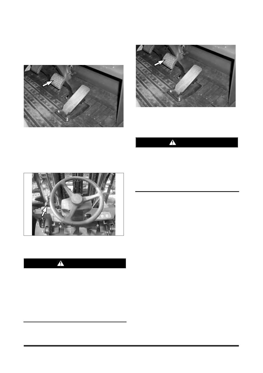
Operation Section
Lift Truck Operation
Power Shift Transaxle
1. Start the engine. See topic “Starting the Engine.”
5. Release the service brake.
6. Push down on the accelerator pedal to obtain the
desired travel speed. Release the pedal to decrease
travel speed.
2. Push down on the service brake pedal to hold the lift
truck until ready to move it.
WARNING
3. Release the parking brake.
Sudden reversal of a loaded lift truck traveling
forward can cause the load to fall or the lift truck
NOTE: The parking brake must be released before
to tip.
the directional control can be used.
Stop the loaded lift truck completely, before
shifting to reverse.
Failure to comply could result in personal injury.
NOTE: Where conditions permit, directional
changes can be made under full power at
speeds up to 6 km/h (3.73mph). A speed of
6 km/h (3.73mph) is a fast walk. Directional
shift changes at speeds above 6 km/h
(3.73mph) are considered abusive.
Bring the lift truck to a complete stop where load
4. Select the direction of travel by pushing the
stability or other factors prevent safe operation
directional lever FORWARD for forward direction or
under full power shifts.
by pulling the lever BACK for reverse direction.
WARNING
A lift truck with the engine running but without
an operator can move slowly (creep) if the
transmission is engaged.
This could result in personal injury.
Always place the transmission control lever in
the NEUTRAL (centre) position and apply the
parking brake before dismounting the lift truck.
-84-
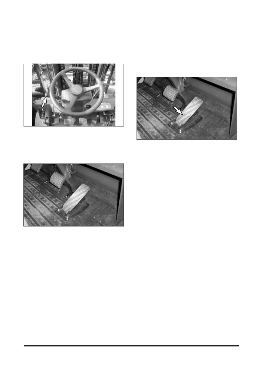
Operation Section
7. To change the lift truck direction of travel, release
Inching
the accelerator pedal.
NOTE: The purpose of the inching pedal is to
8. Push down on the service brake pedal to reduce the
provide precise lift truck inching control at
lift truck speed as necessary.
very slow travel speed and high engine rpm.
This is used for fast hydraulic lift, during
load approach, pick up or load positioning.
9. Move the directional lever to the desired direction of
travel. Slowly push down on the accelerator pedal
as the lift truck changes direction.
1. To inch (creep) in either direction, slowly push down
10. When the direction change is completed, continue
on the inching pedal. This will start to apply the
to push down on the accelerator pedal to obtain the
service brakes and allow the transmission clutch
desired travel speed.
discs to slip.
2. Vary the position of the inching pedal and the
accelerator pedal to control the inching speed and
distance.
3. Pushing down further on the inching pedal will
disengage the transmission completely and apply
the service brakes fully to stop and hold the lift truck.
This will provide full engine power for fast hydraulic
lift.
4. Avoid overuse of the inching pedal as this may cause
the automatic transmission oil to overheat or the
clutch to slip. Do not use as a footrest or for long
11. To stop the lift truck when traveling in either
periods of time.
direction, release the accelerator pedal.
5. If user operates continuously pushing work or both
12. Push down on the service brake pedal and bring the
brake pedal and accelerator pedal were depressed
lift truck to a smooth stop.
at the same time, it may cause the automatic
transmission oil to overheat or the clutch to slip.
-85-
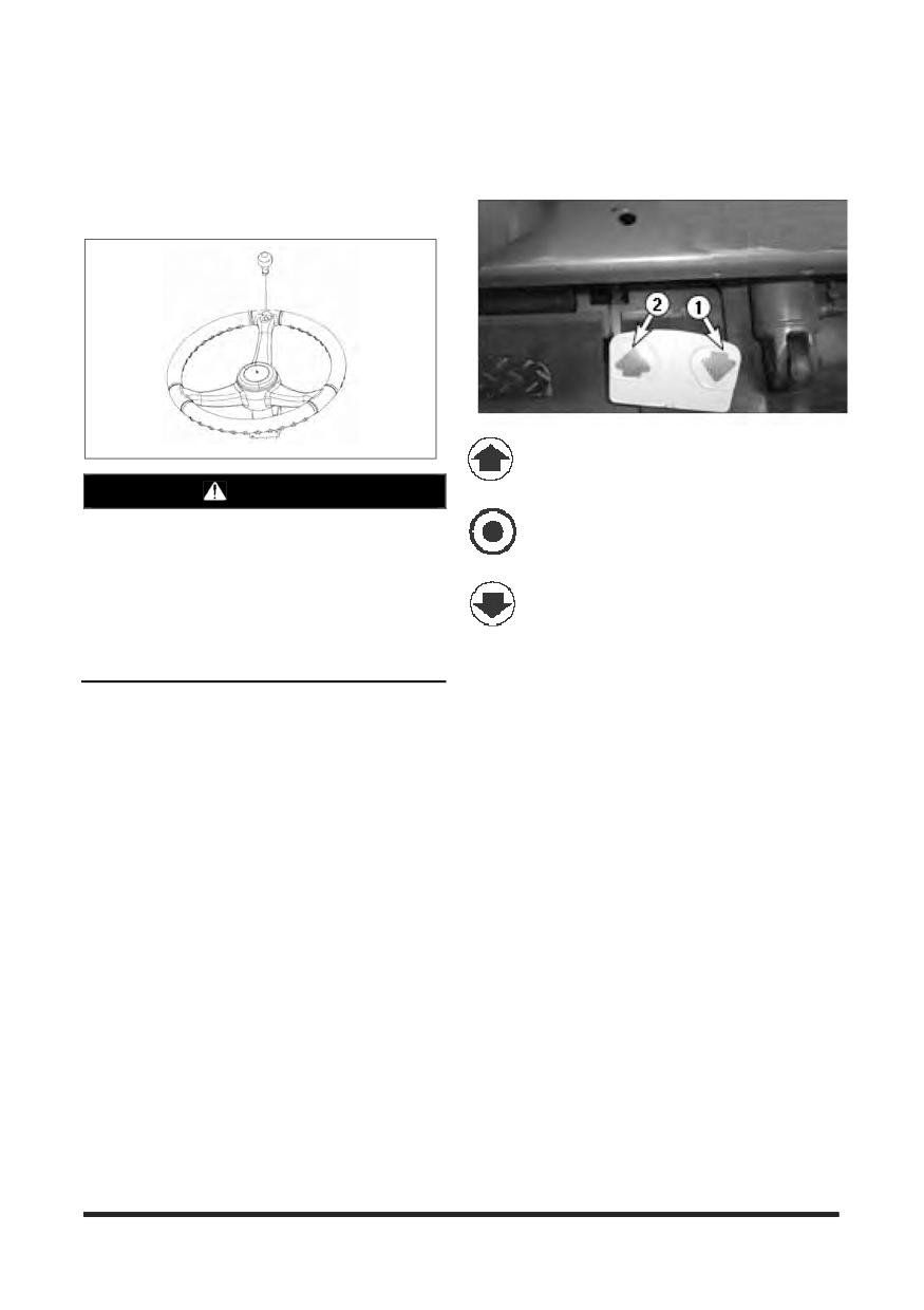
Operation Section
Steering Knob (If Equipped)
Mono-Ped Control System
There is a steering knob available for inclusion with
(Option)
new truck deliveries. This option is solely intended
for slow travel situations when two handed steering
is not possible due to hydraulic operations.
Forward-Push the left side (2) of the pedal
for FORWARD direction travel.
WARNING
Loss of stability can occur when a lift truck
Neutral-The lift truck should not move when
steering wheel is rotated quickly while the truck
the Mono-Ped pedal is released..
is in motion. A steering knob will assist with
easy rotation of the steering wheel, but if a
Reverse-Push the right side (1) of the pedal
steering knob is improperly used (e.g., rotating
for REVERSE direction travel.
the steering wheel quickly while the truck is in
motion), this can contribute to truck instability
and a tip over. A steering knob is intended for
The MONO-PED pedal controls the speed and
slow travel maneuverability ONLY.
direction of the lift truck. Pushing on the right side of
the pedal
(1) causes the lift truck to move in
REVERSE. The optional reverse lights and optional
back-up alarm will be ON in the REVERSE position.
Pushing on the left side of the pedal (2) causes the
lift truck to move in FORWARD.
The speed of the truck increases as the pedal is
depressed
-86-
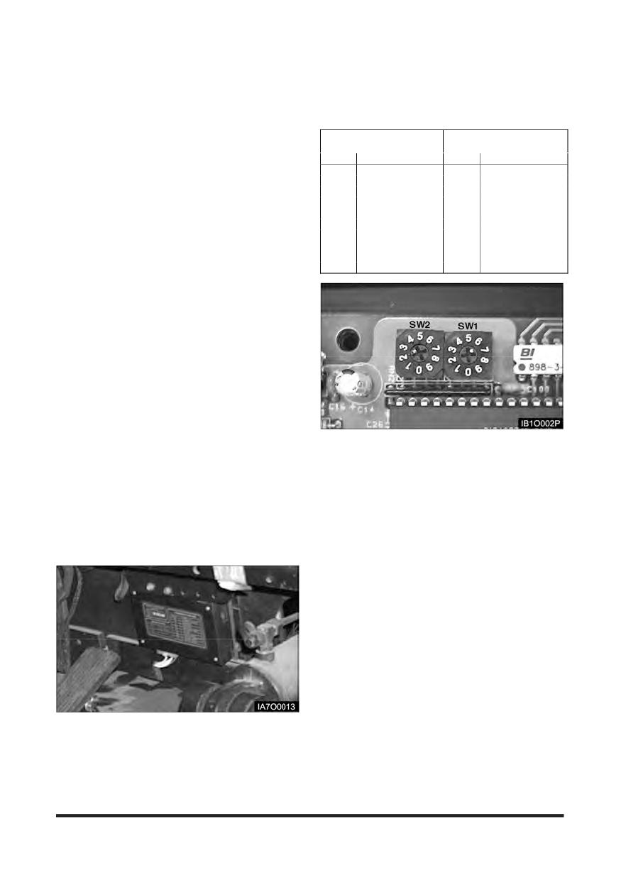
Operation Section
Auto Shift Controller ASC - 206 (Standard)
Adjustments
Product Description
SW1
SW2
The Autoshift controller is an electrical control system,
( Low-High Shift Point ) ( Direction Inhibit Point )
specially designed for use on forklift trucks with internal
NOTCH
Vehicle Speed
NOTCH
Vehicle Speed
combustion engines.
0
2.5 km/h (1.55 mph)
0
3.3 km/h (2.05 mph)
Its primary purpose is to prevent the operator from
1
3.0 km/h (1.86 mph)
1
3.6 km/h (2.24 mph)
operating the truck outside of the design parameters,
2
3.5 km/h (2.17 mph)
2
3.9 km/h (2.42 mph)
e.g. selecting the reverse gear when traveling in
3
4.0 km/h (2.49 mph)
3
4.2 km/h (2.61 mph)
excess of 6.0 km/h ( 3.73mph ) in a forward direction,
4
4.5 km/h (2.80 mph)
4
4.5 km/h (2.80 mph)
and vice versa.
5
5.0 km/h (3.11 mph)
5
4.8 km/h (2.98 mph)
6
5.5 km/h (3.42 mph)
6
5.1 km/h (3.17 mph)
The Autoshift controller is mounted on a convenient
7
6.0 km/h (3.73 mph)
7
5.4 km/h (3.36 mph)
position away from excessive heat sources and
8
6.5 km/h (4.04 mph)
8
5.7 km/h (3.54 mph)
retrofits into the truck’s electrical system. An
9
7.0 km/h (4.35 mph)
9
6.0 km/h (3.73 mph)
inductive speed sensor is mounted on the
transmission case where it will pick up a pulse from
a gear tooth pattern. This pulse is used to monitor
the truck in motion and its travel speed. To enable
the system to change gears smoothly, the shift
points for offset speed are adjustable.
An operator no longer has to change gears with his
hands, therefore he can be more productive.
The Autoshift controller prevents strain and abuse to
the transmission by changing gears up and down
automatically. It also prevents damage to the half
shaft, excessive tyre wear and heat to the
transmission.
Adjustment Switch
Features
Low-High Shift Point (SW1)
1. 2 - speed auto shift control
ASC-206 allows you to set the 2 speed Auto Gear Shift
Point, the maximum travel speed at which the Auto Shift
2. Prevent downshifting at high speed
Controller up-shift or down-shift the transmission
automatically according to the vehicle speed. For
3. Inhibit selecting direction at high speed outside of
adjustment of 2 speed Auto Gear Shift speed, the SW1
the design parameters.
switch is used on the printed circuit board.
For example if SW1 put to 5th notch, the 2 Speed
Auto Gear Shift speed will be 5.0 km/h(3.11 mph),
which is factory setting value as a default.
Direction Inhibit Point (SW2)
Auto Shift allows you to set the Direction Inhibit Speed,
the maximum travel speed at which the transmission
can be reversed. For adjustment of direction inhibit
speed, the SW2 switch is used on the printed circuit
board.
For example SW2 is put to 7rd notch, the Direction
Inhibit Speed will be 5.4 km/h (3.36 mph), which is
factory setting value as a default.
-87-
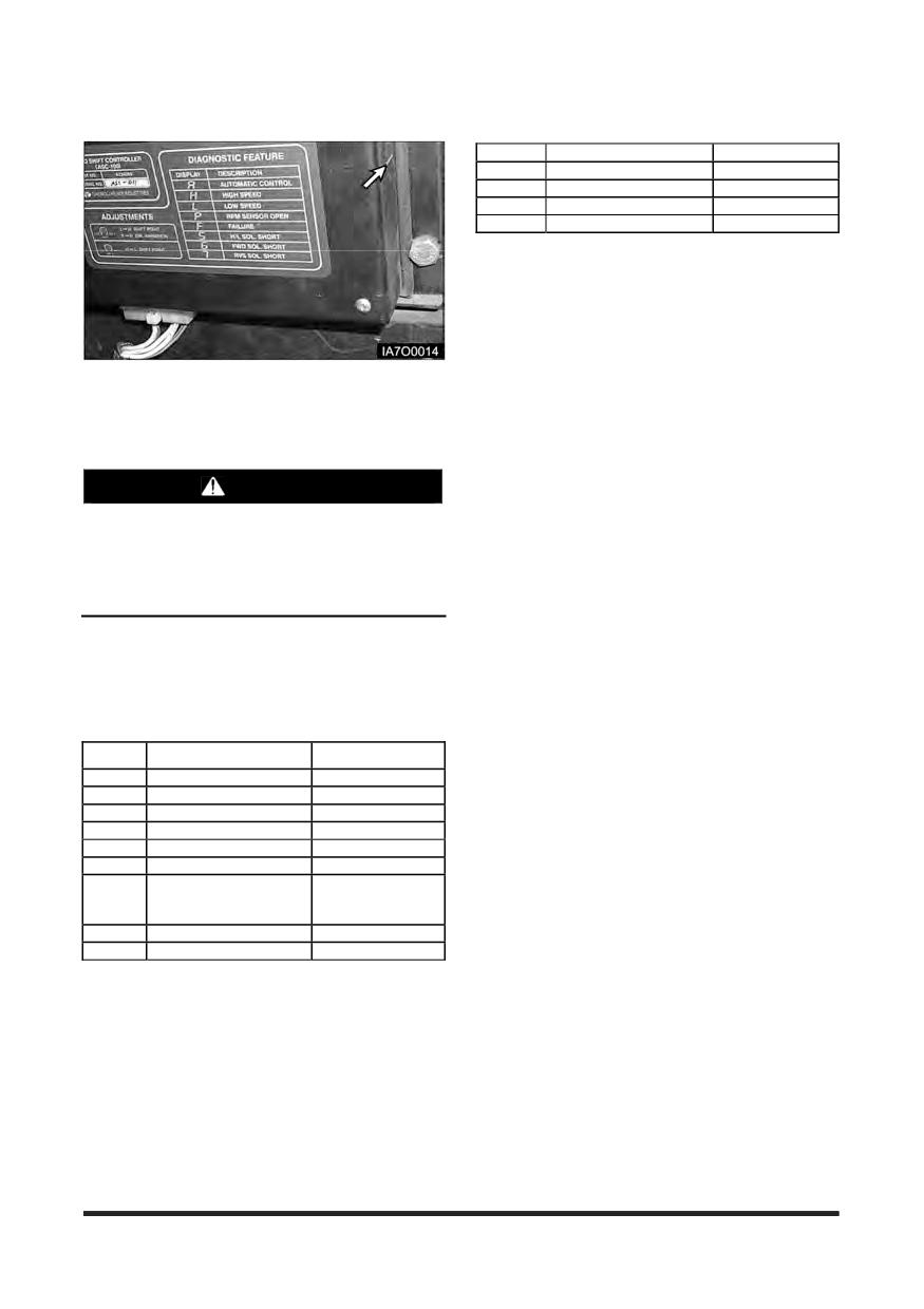
Operation Section
Diagnostics Features
Display for Troubleshooting
Display
Description
Remark
A
Automatic operation
2
High speed s/w input
Lever input test
3
Forward s/w input
Lever input test
4
Reverse s/w input
Lever input test
This information is input for signal diagnostics.
This test is used to verify operation of direction
control lever.
Operation
ASC-206 has internal indicator on the right side of
This system can be basically operated in two
the controller for displaying the selected gear and
preselected modes, automatic mode and manual mode.
the abnormal condition.
Automatic Mode is selected in factory-setting controller
as a default.
Manual Mode (Fail-Safe Mode) is selected to
operate the truck manually in case of emergency.
WARNING
Do not diagnose or repair Auto Shift Controller
Faults unless trained and authorised to do so.
Automatic mode
Improper
performance
of
maintenance
Direction Inhibit
procedures is dangerous and could result in
personal injury or death.
1. Start the engine with the direction control lever in
NEUTRAL and the parking brake engaged.
Below is a description applicable for many ASC-500
2. Press down on the service brake pedal, disengage
implementations.
the parking brake and move the direction control
lever to FORWARD.
Display for Operator
NOTE: Release the parking brake before using the
directional control lever.
Display
Description
Remark
3. Observe the LED on the Auto Shift Controller. The
A
Automatic operation
LED should indicate “A” while the direction control
H
High speed
At 2nd shift gear
lever is in FORWARD, NEUTRAL and REVERSE.
L
Low speed
At 1st shift gear
Report Auto Shift as faulty if the LED indicates
P
T/M Speed sensor open
Flashing
anything other than “A”.
E
E/G Speed sensor open
Flashing
F
Controller fault
Flashing
4. Keep the service brake pushed down until ready to
FWD 2 Sol. Short
move the truck.
5
or
Flashing
5. To change directions of a traveling lift truck when
REV 2 Sol. Short
the Auto Shift Controller LED displays “A”, shift the
6
FWD 1 Sol. Short
Flashing
direction control lever to the opposite direction and
7
REV 1 Sol. Short
Flashing
wait for the lift truck to change direction.
This information is given during normal operating when
6. If however, your travel speed is higher than the pre-
something special happens.
selected direction change speed as direction inhibit
For example, on ASC-500’s with the speed sensor,
point in the controller, Auto Shift will shift the
one of the indicators is used to indicate a sensor
transmission to NEUTRAL until the lift truck’s travel
problem.
speed slows to the pre-selected direction change
speed, and then shift the transmission to the
direction selected.
7. You should be prepared to help slow the lift truck to
the pre-selected direction change speed by
pressing down on the service brake pedal.
-88-
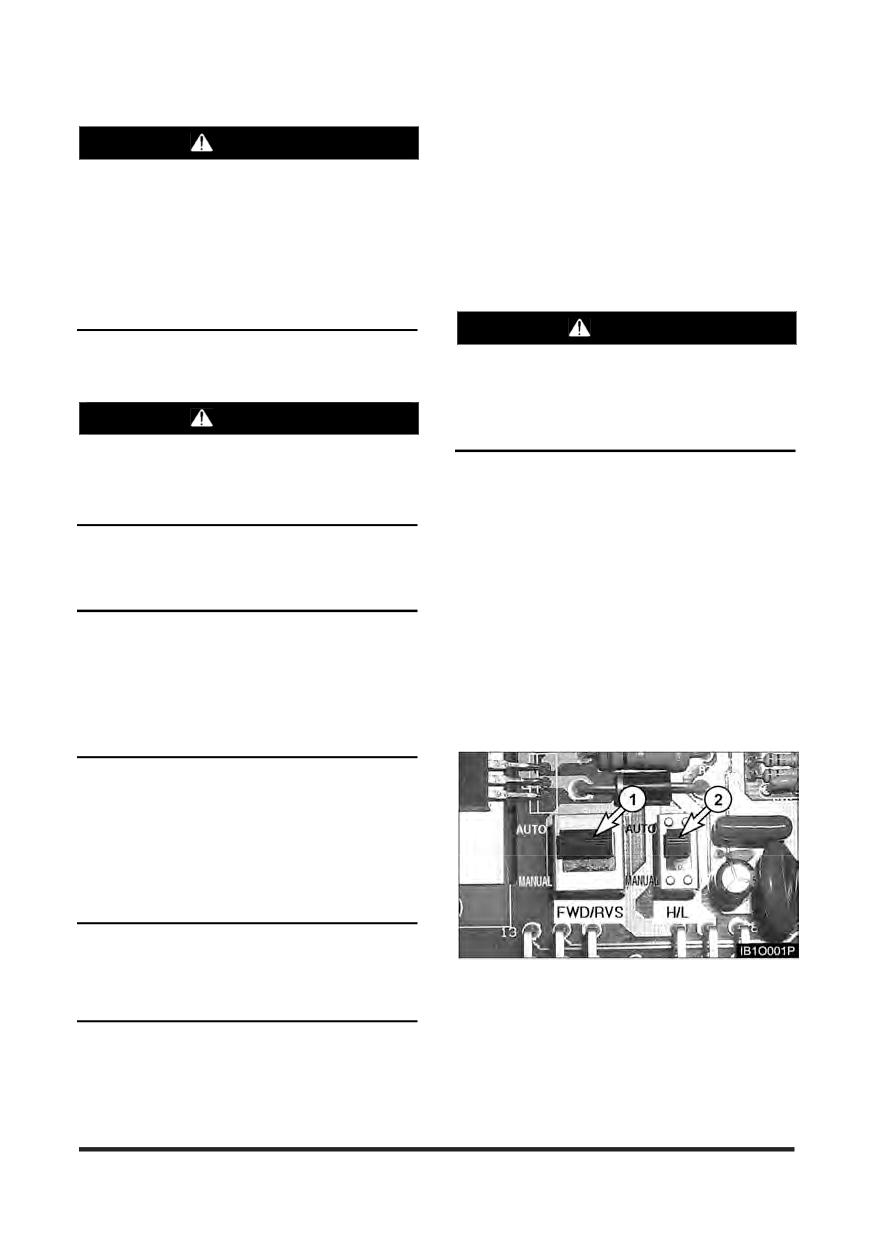
Operation Section
Manual Mode (Fail-Safe mode)
WARNING
In case that the controller is broken down or you
When you want to change the travel direction,
don’t want to use the functions of the Auto Shift
you must press down on the service brake
Controller, you can select Manual Mode. In Manual
pedal to reduce the travel speed. Be cautious
Mode, you can operate your lift truck in the same
that the lift truck’s stopping distance may be
manner as any lift truck without Auto Shift
longer than in manual mode because the lift
Controller. You can select the Manual mode or the
truck continues to travel forward regardless of
Automatic mode by doing following procedures.
the selection of reverse with the direction
control lever until the vehicle speed is
sufficiently reduced.
WARNING
8. The direction of travel will change automatically
when the vehicle speed is reduced as much as the
In the manual mode, direction inhibition
pre-selected speed in the controller.
function can not be operated normally. The
sudden reversal of a loaded lift truck traveling
forward can cause the load to fall or the lift
WARNING
truck to tip over.
Bring the loaded lift truck to a complete stop
before changing travel direction.
An operator can operate the truck manually by
Changing travel direction while traveling may
selecting the Manual mode with the Fail-Safe mode
cause the lift truck to lose the load or tip over.
switches on the PCB (Printed Circuit Board).
With the switch (1) in “MANUAL” position, direction
inhibit function is disable.
9. When the direction change is completed, continue
If an operator moves the switch (2) from “AUTO”
to push down on the accelerator pedal to obtain the
position to “MANUAL” position, then 2-speed auto shift
desired travel speed.
function will become disabled.
Move the switches as indicated, up of Automatic
NOTICE
(AUTO) operation or down for Manual (MANUAL)
operation.
The transmission of your lift truck may be reversed
under full power up to a travel of 6.0 km/h (3.73 mph).
But the Inhibit Speed of Auto Shift is set by the factory at
NOTE: In the factory-setting controller, AUTO
5.4 km/h (3.36 mph) because reversing the transmission
mode is selected as a default on the PCB
at lower travel speeds prolongs the lift of the
(Printed Circuit Board) as shown below.
transmission, axle shafts and tyres.
Two-Speed Auto Shift Control
While traveling forward with the high speed gear,
that is, 2nd gear selected, the ASC-206 can up-shift
or down-shift the transmission automatically
according to the vehicle speed by its own speed
ratio control so that the appropriate gear may be
engaged in every situation.
NOTICE
Two-Speed Auto Shift Control function can be
accomplished only when the direction control lever is
NOTE: After operating the truck manually by
placed in the high speed (2nd gear) position.
selecting the Manual Mode switch on
PCB(Printed Circuit Board), the position of
mode must be checked before operating
the truck automatically.
-89-
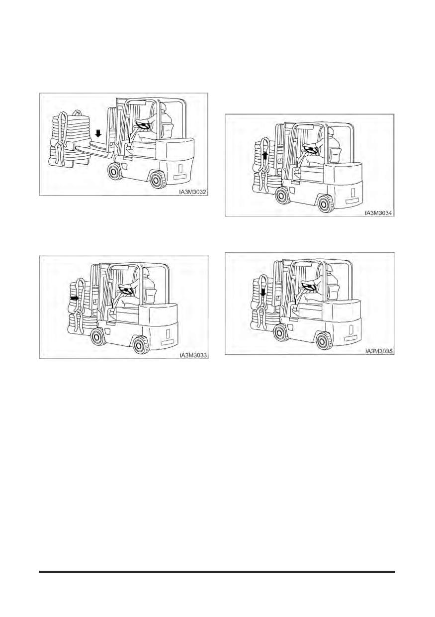
Operation Section
Operating Techniques
Inching into Loads
Lifting the Load
1. Lift the load carefully and tilt the mast back a short
distance.
Typical Example
1. Move the lift truck slowly FORWARD into position
Typical Example
and engage the load. The lift truck should be square
with load, forks spaced evenly between pallet
2. Tilt the mast further back to cradle the load.
stringers and as far apart as load permits.
Typical Example
Typical Example
3. Operate the lift truck in reverse until the load is clear
2. Move the lift truck FORWARD until the load touches
of the other material.
the carriage.
4. Lower the cradled load to the travel position.
NOTE: Lift and tilt speeds are controlled by engine
rpm.
-90-
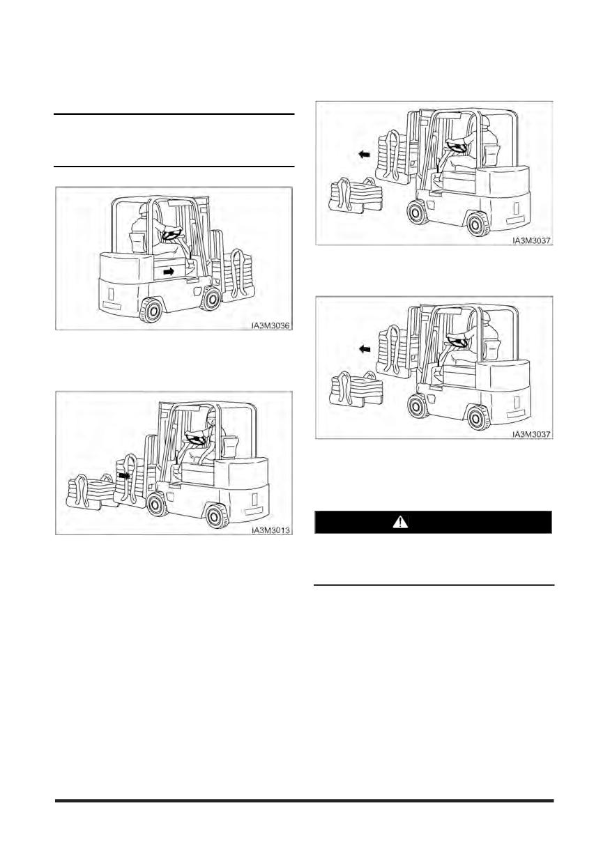
Operation Section
Unloading
Traveling With the Load
NOTICE
Travel with the load as low as possible, while still
maintaining ground clearance.
Typical Example
1. Move the lift truck into the unloading position.
Typical Example
1. Travel with the load uphill on upgrades and
downgrades.
Typical Example
2. Tilt the mast FORWARD only when directly over the
unloading area.
WARNING
Typical Example
Do not tilt the mast forward with the load unless
directly over the unloading area, even if the
2. For better vision, travel in reverse with bulky loads.
power is off.
-91-
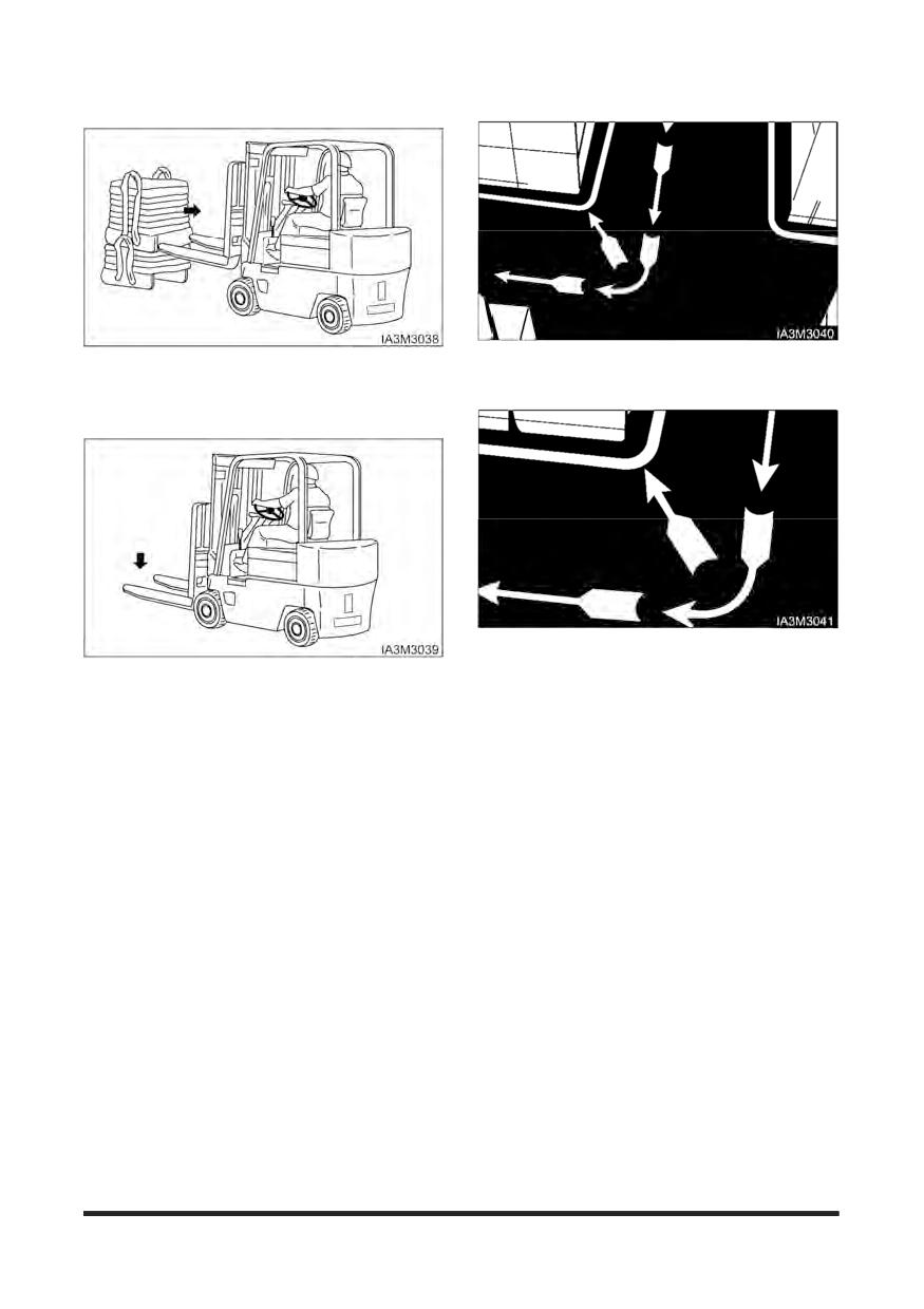
Operation Section
Typical Example
1. When turning sharp corners, keep close to the
inside corner. Begin the turn when the inside drive
3. Deposit the load and BACK away carefully to
wheel meets the corner.
disengage the forks.
2. In narrow aisles, keep away from the stockpile when
turning into the aisle. Allow for counterweight swing.
Typical Example
4. Lower the carriage and forks to the travel position or
to the park position.
-92-
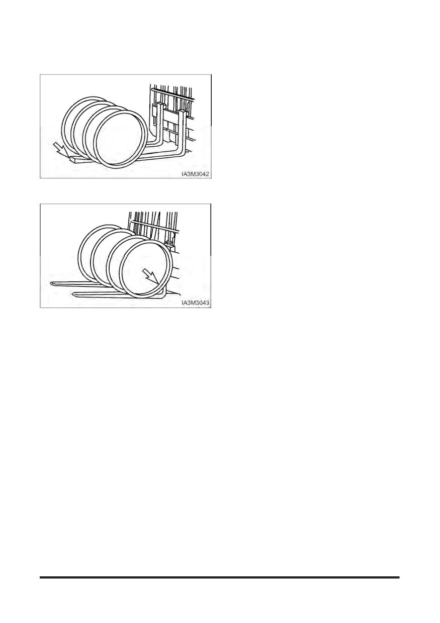
Operation Section
Operating in hot weather
Lifting Drums or Round Objects
Keep the following points in mind when you operate
the lift truck in hot weather.
1. Check the radiator. Clogging can cause overheating.
Clean them out regularly with a blast of compressed
air, also, check for leakage of water.
2. Check the fan belt tension and adjust to proper
tension.
3. Even if the engine overheats and the coolant boils
over, let the engine idle for a while with opening
engine hood until temperature falls before shutting
off the engine.
1. Block drums or round objects. Tilt the mast
FORWARD and slide the fork tips along the floor
2. Before lifting, tilt the mast BACK slightly until the
load is cradled on the forks.
-93-
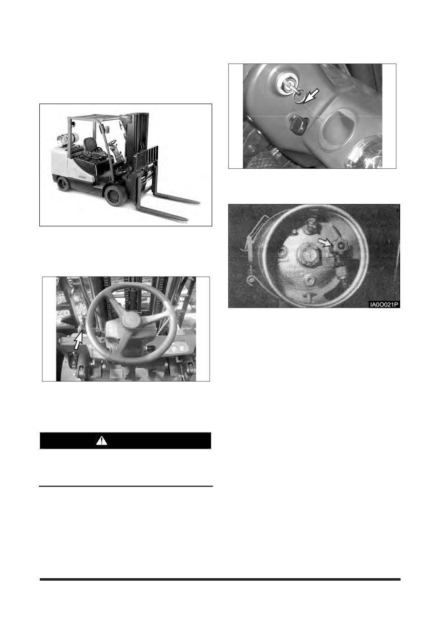
Operation Section
Parking the Lift Truck
Park the lift truck level, with the forks lowered and the
mast tilted forward until the fork tips touch the floor.
Block the drive wheels when parking on an incline.
5. Turn the key in the ignition switch to the OFF
position and remove the key.
1. Park in an authorised area only. Do not block traffic.
If LP equipped, do not park near elevator shafts or
any other area where LP could collect in a pocket
(low area), causing a potentially dangerous
condition.
NOTE: If a LP equipped lift truck is stopped or
parked for an indefinite or prolonged period
of time, close the fuel shutoff valve on the
LP tank. Run the engine until fuel in the line
runs out and the engine stops. Turn off the
ignition switch and disconnect switch (if
equipped).
6. Actuate each loading lever several times to remove
2. Place the transmission controls in NEUTRAL.
the residual pressure in the respective cylinders and
hoses.
3. Engage the parking brake.
7. Block the drive wheels if parking on an incline.
4. Lower the forks to the ground.
WARNING
Blocking the wheels will prevent unexpected lift
truck movement, which could cause personal
injury.
-94-
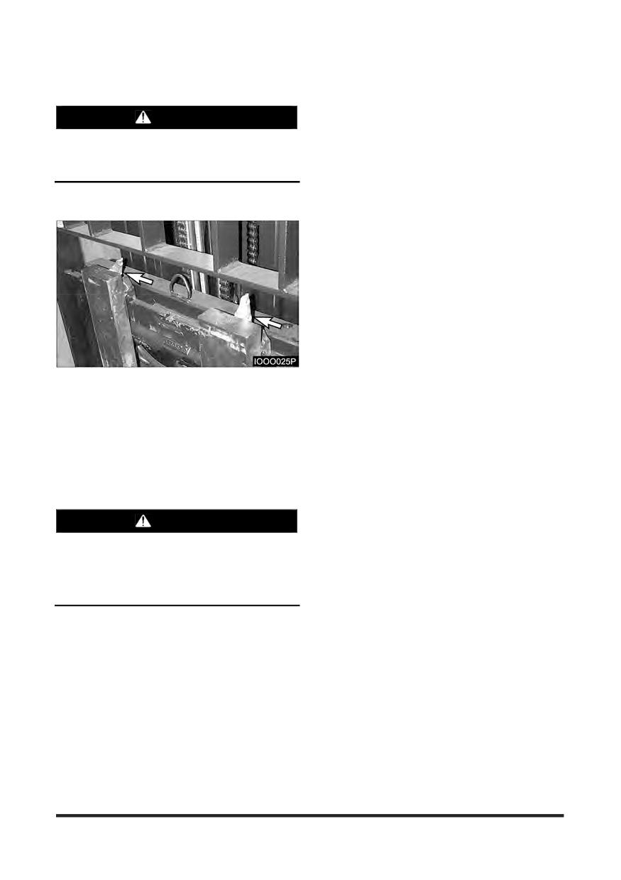
Operation Section
Lift Fork Adjustment
WARNING
When adjusting the fork spread, be careful not to
pinch your hand between forks and the carriage
slot.
Hook - on type Fork
1. Move up the hook pin to the free position.
2. Raise the hook pin in each fork to side the fork on
the carriage bar.
3. Adjust the forks in the position most appropriate for
the load and as wide as possible for load stability.
4. When adjusting the forks, make sure that the weight
of the load is centreed on the truck.
5. After adjustment, set the fork locks to keep the forks
in place.
WARNING
Make sure the forks are locked before carrying a
load.
If the fork/locking pin is not fully engaged, the
fork could become unintentionally disengaged.
-95-
Operation Section
Storage Information
Before Storage
To Operate the Lift Truck After a
Before storing your lift truck, clean and inspect as
Long Time Storage
the following procedures.
Remove covers and antirust from each of the
Wipe away grease, oil, etc. adhering to the body of
components and exposed parts.
the truck with waste cloth, and use water, if needed.
Drain the engine crankcase, transmission (clutch
While cleaning the truck, check general condition of
type machine), differential and final reduction gear,
the truck. Especially check the truck body for dents
clean the inside of them and add new oil.
or damage and tyres for wear or nails or stones in
Drain off foreign matter and water from the
the tread.
hydraulic oil tank and fuel tank.
Fill the fuel tank with fuel specified.
Remove the head cover from the engine cylinder.
Check for leakage of hydraulic oil, engine oil, fuel, or
Oil valves and rocker shaft and check each valve
coolant, etc.
for proper operation.
Apply grease, where needed.
Add cooling water to the specified level.
Charge the battery and mount it on the machine.
Check for looseness of nuts and bolts, especially
hub nuts.
Connect the cables.
Check mast rollers to see that they rotate smoothly.
Perform pre-operational checks carefully. (refer to
“Before Starting the Engine”)
Prime the oil into the lift cylinders by actuating the lift
lever all the way several times.
Warm up the machine.
Drain off coolant completely in cold weather, if
antifreeze is not used.
Long Time Storage
Perform the following service and checks in addition
to the “Parking the lift truck” services.
Taking the rainy season into consideration, park the
machine at a higher and hard ground.
Avoid parking on soft grounds such as asphalt
ground in summer.
Dismount the battery from the machine. Even
though the machine is parked indoors, if the place is
hot or humid, the battery should be kept in a dry,
cool place. Charge the battery once a month.
Apply antirust to the exposed parts which tend to
rust.
Cover components such as the breather and air
cleaner which may be caught with humidity.
The machine should be operated at least once a
week. Fill the cooling system, if cooling water is
discharged, and mount the battery. Start the engine
and warm up thoroughly. Move the machine a little
forwards and backwards. Operate the hydraulic
controls several times.
-96-
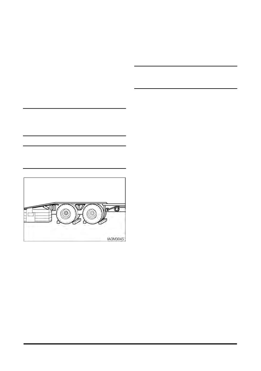
Operation Section
Transportation Hints
Machine Lifting and Tiedown
Lift Truck Shipping
Information
Check travel route for overpass clearances. Make
sure there is adequate clearance if the lift truck
being transported is equipped with a high mast,
NOTICE
overhead guard or cab.
Improper lifting or tiedowns can allow load to shift
To prevent the lift truck from slipping while loading,
and cause injury and/or damage.
or shifting in transit, remove ice, snow or other
slippery material from the loading dock and the truck
1. Weight and instructions given herein apply to lift
bed before loading.
trucks as manufactured by CROWN.
2. Use proper rated cables and slings for lifting.
NOTICE
Position the crane for level lift truck lift.
Obey all state and local laws governing the height,
3. Spreader bar widths should be sufficient to prevent
weight, width and length of a load.
contact with the lift truck.
Observe all regulations governing wide loads.
4. Use the tiedown locations provided for lift truck
tiedown.
Check the state and local laws governing weight,
NOTICE
width and length of a load.
Remove ice, snow or other slippery material from
Contact your CROWN Lift Truck dealer for shipping
the shipping vehicle and the loading dock.
instructions for your lift truck.
Always block the trailer or the rail car wheels before
loading the lift truck.
Position the lift truck on the truck bed or the rail car.
Apply the parking brake and place the transmission
control in NEUTRAL.
Turn the ignition switch to the OFF position and
remove the key. If LP equipped, shut off the LP fuel
tank.
Block the wheels and secure the lift truck with
tiedowns.
-97-
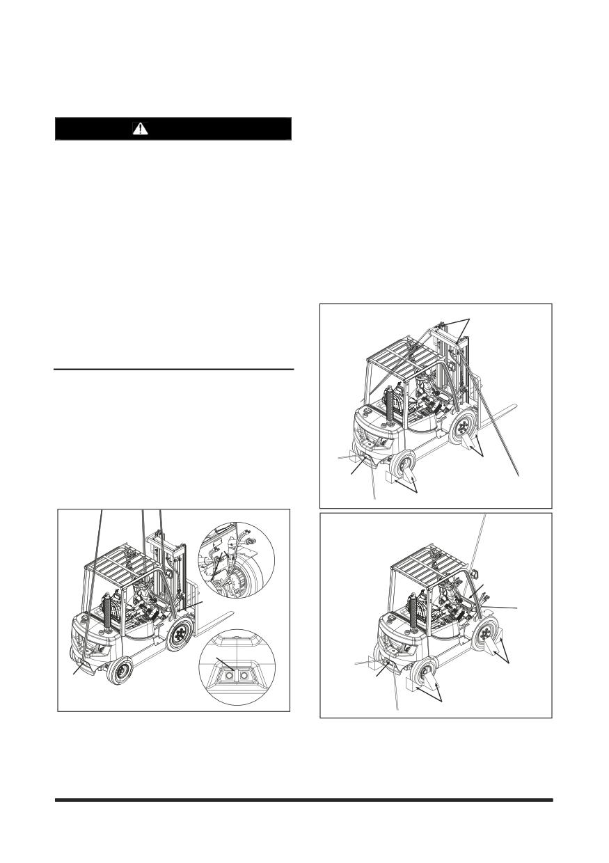
Operation Section
How to Fix Forklift to a Carrier
Lifting a Forklift using a Crane
1. The rope/chain must have sufficient length for
fixing.
WARNING
2. Park the vehicle on a level ground.
1. If lifting rope breaks, serious injury/damage
3. Set the mast vertically. Lower the fork or
may occur.
attachment to the lowest position.
2. The lifting wire rope and stay must be long
4. Set all the operating devices to Neutral Position.
enough to avoid contact with the forklift. Short
Turn OFF the start switch.
rope/stay can damage the vehicle. If it's too long,
it may cause interference.
5. Apply the parking brake. Stop the tyres with
blocks (C).
If sling and LP tank contact happens during
refloatation operation, you should get rid of tank
6. Connect towing hooks to the mast top B (if
of vehicle with LP tank first, and then proceed.
without mast, front drive axle fix frame or front
fender bottom fixing hole D) and rear tow pin A, as
Cover the rope/chain with rubber or cloth to
shown in the figure below.
prevent damage to the vehicle, as necessary.
3. Rope/chain and other lifting tools must have
B
sufficient strength, and free of any defect or
wear.
4. Avoid impact load to the lifting devices/tools.
1. Check the weight, length, width and height of the
vehicle before lifting.
2. Park the crane at an appropriate position.
3. Connect the rope/chain to the points A and B of
the figure below.
C
4. If the wire rope/chain contacts the vehicle, insert a
rubber plate between the rope/chain and the vehicle
A
to protect the vehicle.
C
B
D
B
A
C
A
A
C
5. Lift up the vehicle slowly.
-98-
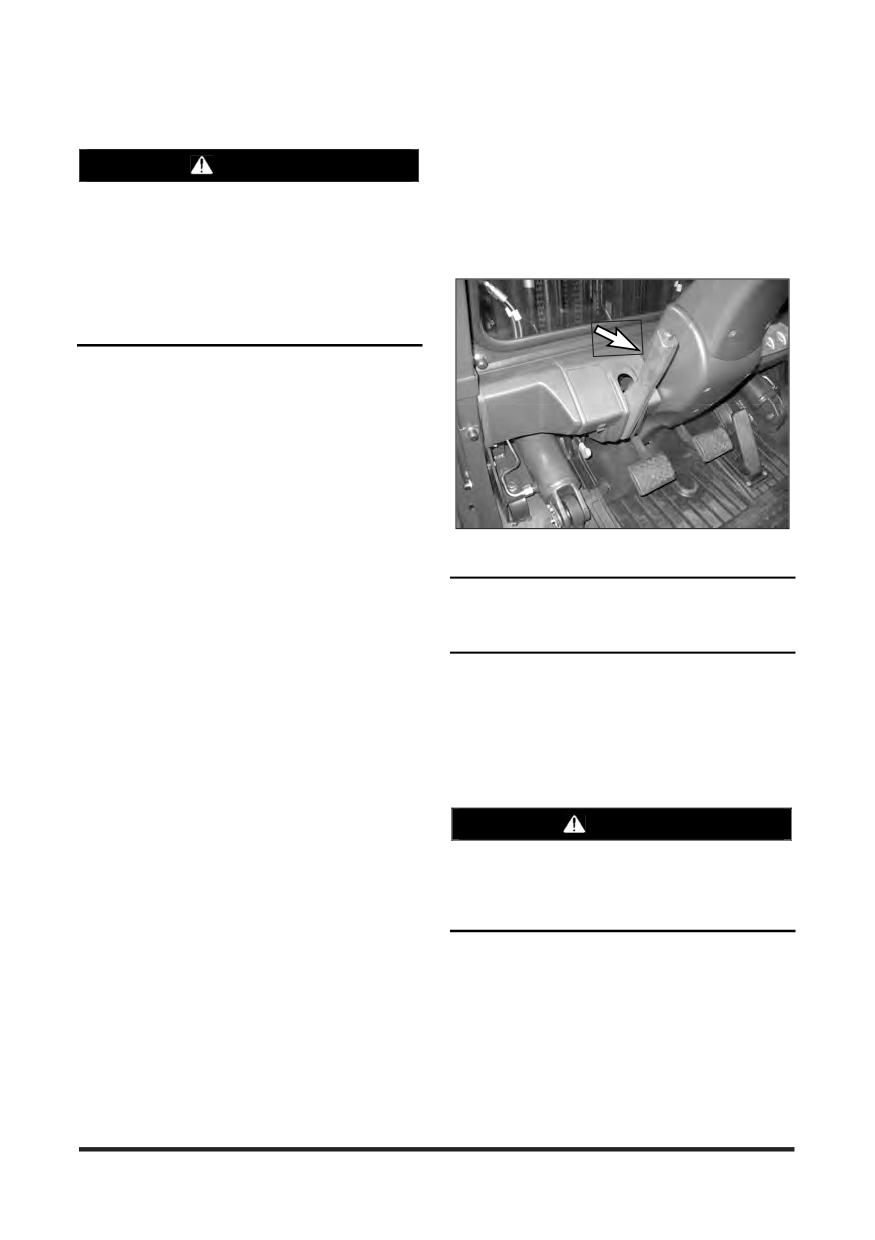
Operation Section
Towing Information
The different situation requirements cannot be given
WARNING
as minimal towing lift truck capacity is required on
smooth level surfaces to maximum on inclines or
Personal injury or death could result when
poor surface conditions.
towing a disabled lift truck incorrectly.
Consult your CROWN Lift Tuck dealer for towing a
Block the lift truck wheels to prevent movement
disabled lift truck.
before releasing the brakes. The lift truck can
roll free if it is not blocked.
Follow the recommendations below, to properly
perform the towing procedure.
These towing instructions are for moving a disabled
lift truck a short distance, at low speed, no faster
than 2 km/h (1.2 mph), to a convenient location for
repair. These instructions are for emergencies only.
Always haul the lift truck if long distance moving is
required.
Shield must be provided on the towing lift truck to
protect the operator if the tow line or bar should
break.
Do not allow riders on the lift truck being towed
1. Release the parking brake.
unless the operator can control the steering and/or
braking.
NOTICE
Before towing, make sure the tow line or bar is in
good condition and has enough strength for the
Release the parking brake to prevent excessive
towing situation involved. Use a towing line or bar
wear and damage to the parking brake system.
with a strength of at least 1.5 times the gross weight
of the towing lift truck for a disabled lift truck stuck in
2. Check that the service brake pedal is released.
the mud or when towing on a grade.
3. Key switch is in the OFF position.
Keep the tow line angle to a minimum. Do not
exceed a 30°angle from the straight ahead position.
4. Direction control lever is in neutral.
Connect the tow line as low as possible on the lift
5. Fasten the tow bar to the lift truck.
truck that is being towed.
6. Remove the wheel blocks. Tow the lift truck slowly.
Quick lift truck movement could overload the tow
Do not tow any faster than 2 km/h (1.2 mph).
line or bar and cause it to break. Gradual and
smooth lift truck movement will work better.
WARNING
Normally, the towing lift truck should be as large as
Be sure all necessary repairs and adjustments
the disabled lift truck. Satisfy yourself that the towing
have been made before a lift truck that has been
lift truck has enough brake capacity, weight and
towed to a service area is put back into
power, to control both lift trucks for the grade and
operation.
the distance involved.
To provide sufficient control and braking when
moving a disabled lift truck downhill, a larger towing
lift truck or additional lift trucks connected to the rear
could be required. This will prevent uncontrolled
rolling.
-99-

Maintenance Section
Jacking Information
WARNING
Hydraulic Jack & Jack Stand
Capacity
Jacking up Truck can be dangerous and should
be done only by trained personnel using proper
Hydraulic Jack Capacity
tools and procedures.
Height
Minimum
Model
Block the lift truck wheels to prevent movement
Minimum*
Requirement
while lifting the wheels. The lift truck can roll
CGC15/18S-5,
free if it is not blocked.
CGC15/18S-5,
100mm
CGC20SC-5
Follow the recommendations below, to properly
1 ton
CD15/18S-5,
2000Kg
4400Ibs
class
perform the jacking procedure.
CD20SC-5,
150mm
CG15/18S-5,
CG20SC-5
CD20/25/
NOTICE
30/33S-5,
Move Trucks to a Secure Non Traffic Maintenance
CD35C-5,
Area with a Level Floor. No Load on Forks.
CG20/25/30E-5,
150mm
Remove key from ignition switch.
CG20/25
2 ton
/30/33P-5,
3000Kg
6600Ibs
class
CG35C-5
CGC20/25/30/
33E-5,
120mm
CGC20/25/30/
33P-5
CD35/40/45S-5,
CD50/55C-5,
CD40/45/50/
3 ton
55SC-5,
180mm
3900Kg
8600Ibs
class
CG35/40/45S-5,
CG50/55C-5,
CG40/45/50/
55SC-5
CD50/60/70/
5 ton
80/90S-5,
250mm
5800Kg
12800Ibs
class
CG50/60/70S-5
11 ton
CD110/130
10000
300mm
22050Ibs
class
/160S-5
Kg
18/20
14000
ton
CDV180/200S-7
350 mm
30900Ibs
Kg
class
25 ton
19000
CDV250S-7
400 mm
42000lbs
class
Kg
• The height of lift truck with a flat tyre is lower than with an
inflated tyre. So Height Minimum of Jack must be less than the
value of the above chart.
Stand Capacity should be more than the minimum
requirement of Hydraulic Jack Capacity.
Hydraulic Jack & Jack Stand are commercially
available and should be especially designed for
forklift trucks.
-100-
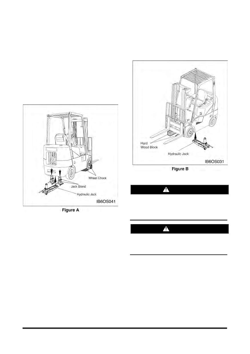
Maintenance Section
Jacking Procedure
Steering Wheel
1. Raise Forks 3 to 6 in (76 to 152 mm) from Floor.
8. Do Not Tilt Mast after Blocked.
2. Place Wheel Chocks under Both Drive Wheels.
3. Locate Hydraulic Jack under Steering Axle as
Shown in Figure A.
4. Jack Up Truck with Hydraulic Jack.
5. Set Jack Stand Height as Required Not to Exceed
16 in (405mm).
WARNING
Locate Hydraulic Jack under Frame. Do NOT
locate on side panel. Do NOT raise side of truck
any more than required to insert hard wood
block.
Side
1. Lower Forks Completely.
WARNING
2. Locate Hydraulic Jack under Frame as Shown in
Figure B.
Locate Hydraulic Jack and Jack Stands under
3. Jack Up One Side of Truck.
steer axle. Do NOT locate Hydraulic Jack or
Jack Stands on Counter Weight.
4. Place Hard Wood Block directly under First Stage
Mast.
5. 1ton/2ton class - Use 6X6 in (150X150mm) Block
3ton/5ton class - Use 8X8 in (200X200mm) Block
11ton class - Use 12X12 in (300X300mm) Block
6. Jack Up Opposite Side of Truck.
7. Place Second Hard Wood Block under Other Side
of First Stage Mast.
-101-
Maintenance Section
Inspection, Maintenance and Repair of Lift Truck Forks
The following section gives practical guidelines for
Users may also refer to the International
inspection, maintenance and repair of lift truck forks.
Organization For Standardization - ISO Technical
It also provides general information on the design
Report 5057 - Inspection and Repair of Fork Arms
and application of forks and the common cause of
and ISO Standard
2330
- Fork Arms-Technical
fork failures.
Characteristics and Testing.
Lift truck forks can be dangerously weakened by
Users should be familiar with the requirements for
improper repair or modification. They can also be
inspection and maintenance of lift trucks as provided
damaged by the cumulative effects of age, abrasion,
by Australian Standard AS2359.
corrosion, overloading and misuse.
A fork failure during use can cause damage to the
equipment and the load. A fork failure can also
Environment Protection
cause serious injury.
When servicing this lift truck, use an authorised
A good fork inspection and maintenance program
servicing area and an approved container to collect
along with the proper application can be very
coolant, oil, fuel, grease, electrolyte and any other
effective in preventing sudden failures on the job.
potential environmental pollutant before any lines,
fittings or related items are disconnected or removed.
Repairs and modifications should be done only by
After servicing, dispose of those materials in an
the fork manufacturer or a qualified technician who
authorised place and container. When cleaning the
knows the material used and the required welding
lift truck, be sure to use an authorised area.
and heat treatment process.
Users should evaluate the economics of returning
the forks to the manufacturer for repairs or
purchasing new forks. This will vary depending on
many factors including the size and type of fork.
Forks should be properly sized to the weight and
length of the loads, and to the size of the machine
on which they are used. The general practice is to
use a fork size such that the combined rated
capacity of the number of forks used is equal to or
greater than the “Standard(or rated) Capacity” of the
lift truck.
The individual load rating, in most cases, will be
stamped on the fork in a readily visible area. This is
generally on the top or side of the fork shank.
A fork rated at 1500 pounds at 24 inch load
centre will be stamped 1500X24.
A fork rated at 2000 kg at 600 mm load centre
will be stamped 2000X600.
The manufacturer identification and year and date of
manufacture is also usually shown.
Some countries have standards or regulations which
apply specifically to the inspection and repair of
forks.
-102-
Maintenance Section
Causes of Fork Failure
Repetitive Overloading
Repetitive cycling of loads which exceeds the
Improper Modification or Repair
fatigue strength of the material can lead to fatigue
failure. The overload could be caused by loads in
Fork failure can occur as a result of a field
excess of the rated fork capacity and by use of the
modification involving welding, flame cutting or other
forks tips as pry bars. Also, by handling loads in a
similar processes which affect the heat treatment
manner which causes the fork tips to spread and the
and reduces the strength of the fork.
forks to twist laterally about their mountings.
In most cases, specific processes and techniques
Wear
are also required to achieve proper welding of the
Forks are constantly subjected to abrasion as they
particular alloy steels involved. Critical areas most
slide on floors and loads. The thickness of the fork
likely to be affected by improper processing are the
blade is gradually reduced to the point where it may
heel section, the mounting components and the fork
not be capable of handling the load for which it was
tip.
designed.
Bent or Twisted Forks
Stress Risers
Forks can be bent out of shape by extreme
Scratches, nicks and corrosion are points of high
overloading, glancing blows against walls or other
stress concentration where cracks can develop.
solid objects or using the fork tip as a pry bar.
These cracks can progress under repetitive loading
in a typical mode of fatigue failure.
Bent or twisted forks are much more likely to break
and cause damage or injury. They should be
Overloading
removed from service immediately.
Extreme overloading can cause permanent bending
or immediate failure of the forks. Using forks of less
Fatigue
capacity than the load or lift truck when lifting loads
Parts which are subjected to repeated or fluctuating
and using forks in a manner for which they were not
loads can fail after a large number of loading cycles
designed are some common causes of overloading.
even though the maximum stress was below the
static strength of the part.
The first sign of a fatigue failure is usually a crack
which starts in an area of high stress concentration
This is usually in the heel section or on the fork
mounting.
As the crack progresses under repetitive load
cycling, the load bearing cross section of the
remaining metal is decreased in size until it
becomes insufficient to support the load and
complete failure occurs.
Fatigue failure is the most common mode of fork
failure. It is also one which can be anticipated and
prevented by recognizing the conditions which lead
up to the failure and by removing the fork service
prior to failing.
-103-
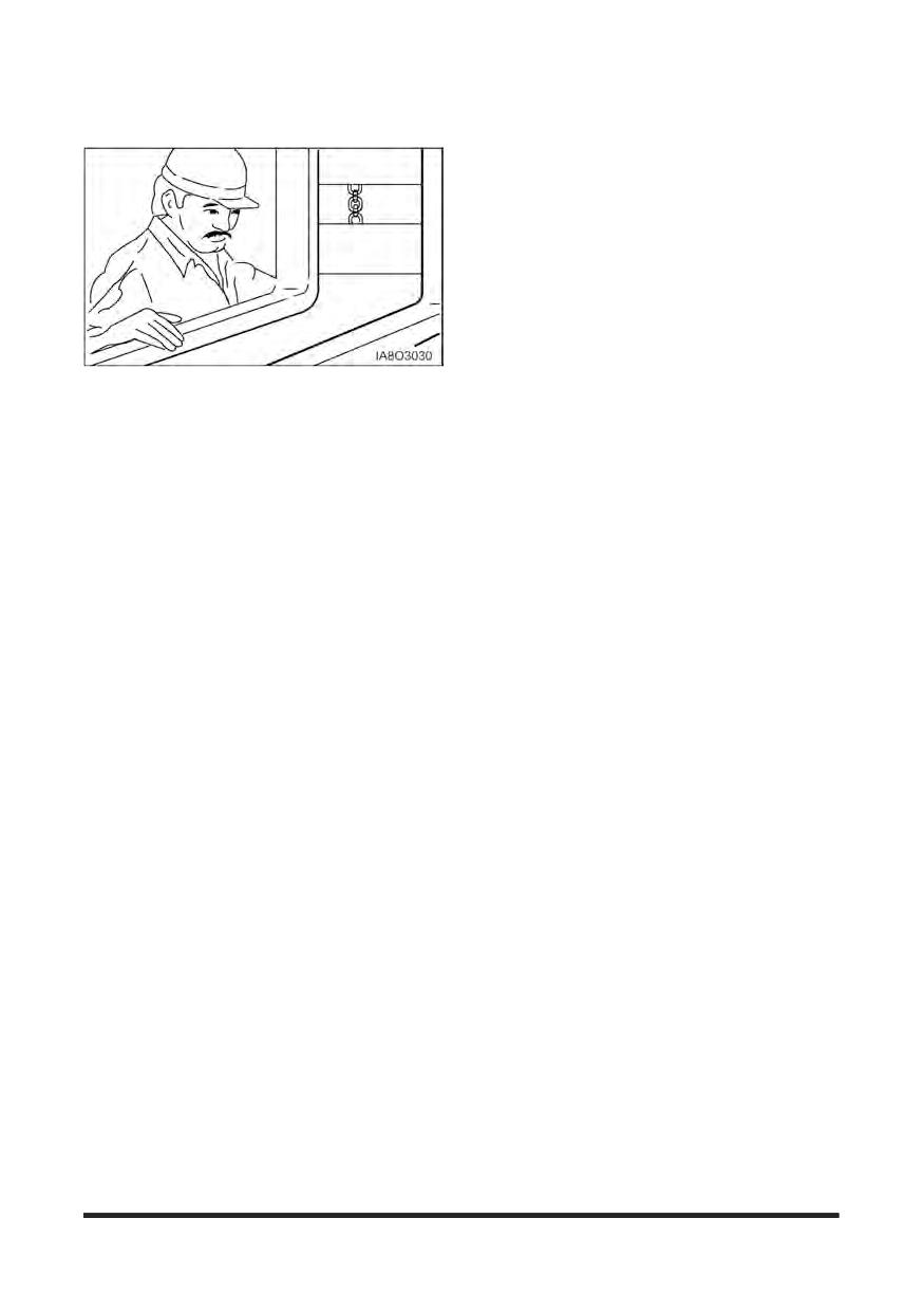
Maintenance Section
Fork Inspection
First Installation
1. Inspect forks to ensure they are the correct size for
the truck on which they will be used. Make sure they
are the correct length and type for the loads to be
handled.
If the forks have been previously used, perform
the “12 Month Inspection”.
If the forks are rusted, see “Maintenance and
Repair”.
2. Make sure fork blades are level to each other within
acceptable tolerances. See “Forks, Step 4,” in the
“2000 Service Hours or Yearly” in “Maintenance
Intervals”
Establish a daily and 12 month inspection routine by
keeping a record for the forks on each lift truck.
3. Make sure positioning lock is in place and working
Lock forks in position before using truck. See “Forks,
Initial information should include the machine serial
Step 7” in the “2000 Service Hours or Yearly” in
number on each the forks are used, the fork
“Maintenance Intervals”.
manufacturer, type, original section size, original
length and capacity. Also list any special
characteristics specified in the fork design.
Daily Inspection
Record the date and results of each inspection,
making sure the following information is included.
1. Visually inspect forks for cracks, especially in the
heel section, around the mounting brackets, and all
Actual wear conditions, such as percent of
weld areas. Inspect for broken or jagged fork tips,
original blade thickness remaining.
bent or twisted blades and shanks.
Any damage, failure or deformation which might
2. Make sure positioning lock is in place and working.
impair the use of the truck.
Lock the forks in position before using the truck.
Note any repairs or maintenance.
See
“2000 Service Hours or Yearly” in
An ongoing record of this information will help in
“Maintenance Intervals”.
identifying proper inspection intervals for each
3. Remove all defective forks from service.
operation, in identifying and solving problem areas
and in anticipating time for replacement of the forks.
-104-
Maintenance Section
12 Months Inspection
fatigue life of the fork. Always grind or polish in the
direction of the blade and shank length.
Forks should be inspected, at a minimum, every 12
Repair or replace the positioning locks on hook type
months. If the truck is being used in a multi-shift or
forks.
heavy duty operation, they should be checked every
six months. See “Forks” in the “2000 Service Hours
Repair or replace most fork retention devices used
or Yearly” in “Maintenance Intervals.”
with other fork types.
4.
A fork should be load tested before being returned
to service on completion of repairs authorised and
Maintenance and Repair
done in accordance with the manufacturer’s
recommendations.
1. Repair forks only in accordance with the
manufacturer’s recommendations.
Most manufacturers and standards require the
repaired fork to be tested with a load 2.5 times
Most repairs or modifications should be done
the specified capacity and at the load centre
only by the original manufacturer of the forks or
marked on the fork arm.
an expert knowledgeable of the materials,
design, welding and heat treatment process.
With the fork restrained in the same manner as
its mounting on the lift truck, apply the test load
2. The following repairs or modifications SHOULD
twice, gradually and without shock. Maintain the
NOT be attempted.
test for 30 seconds each time.
Flame cutting holes or cutouts in fork blades.
Welding on brackets or new mounting hangers.
Check the fork arm before and after the second
Repairing cracks or other damage by welding.
application of the test load. It shall not show any
permanent deformation.
Bending or resetting.
Consult the fork manufacturer for further
3. The following repairs MAY be performed.
information as may be applicable to the specific
Forks may be sanded or lightly ground, to remove
fork involved.
rust, corrosion or minor defects from the surfaces.
Testing is not required for repairs to the
Heel sections may be ground with a carbon stone
positioning lock or the markings.
to remove minor surface cracks or defects. Polish
the inside radius of the heel section to increase the
-105-
Maintenance Section
Torque Specifications
Metric Hardware
Torque for Standard Bolts, Nuts,
Most of the nuts, bolts, studs, and threaded holes in
and Taperlock Studs
your lift truck are metric. In this manual we provide
specifications in both metric and U.S. customary
NOTICE
measurement. Always replace metric hardware with
metric hardware. See the parts books for proper
The two charts below give general torques for bolts,
replacement.
nuts, and taperlock studs of SAE Grade 5 or better
quality.
NOTE: For proper fit, use only metric tools on
metric hardware. Non-metric tools might
slip and cause injury.
Torques for Bolts and Nuts With
Standard Threads
Torque for Standard Hose Clamps
Thread Size
Standard Nut and Bolt Torque
- Worm Drive
Inch
N∙m1
lb∙ft
NOTICE
1/4
12 ± 4
9 ± 3
The chart below gives the torques for initial
5/16
25 ± 7
18 ± 5
installation of hose clamps on new hose and for
3/8
45 ± 7
33 ± 5
reassembly or retightening of hose clamps on
existing hose.
7/16
70 ± 15
50 ± 11
1/2
100 ± 15
75 ± 11
Initial Installation
9/16
150 ± 20
110 ± 15
Clamp Width
Torque On New Hose
5/8
200 ± 25
150 ± 18
N∙m1
lb∙in
3/4
360 ± 50
270 ± 37
16 mm (.625 in)
7.5 ± 0.5
65 ± 5
7/8
570 ± 80
420 ± 60
13.5 mm (.531 in)
4.5 ± 0.5
40 ± 5
1
875 ± 100
640 ± 75
8 mm (.312 in)
0.9 ± 0.2
8 ± 2
1 1/8
1100 ± 150
820 ± 110
1 1/4
1350 ± 175
1000 ± 130
Reassembly Or
1 3/8
1600 ± 200
1180 ± 150
Clamp Width
Retightening Torque
1 1/2
2000 ± 275
1480 ± 200
N∙m1
lb∙in
1 1 Newton meter (N∙m) is approximately the same as 0.1
16 mm (.625 in)
4.5 ± 0.5
40 ± 5
kg∙m.
13.5 mm (.531 in)
3.0 ± 0.5
25 ± 5
8 mm (.312 in)
0.7 ± 0.2
6 ± 2
1 1 Newton meter (N∙m) is approximately the same as 0.1
kg∙m.
-106-
Maintenance Section
Torques for Taperlock Studs
Torque for Metric Fasteners
NOTICE
Thread Size
Standard Taperlock Stud Torque
Be very careful never to mix metric with U.S.
Inch
customary (standard) fasteners. Mismatched or
N∙m1
lb∙ft
incorrect fasteners will cause lift truck damage or
malfunction and may even result in personal injury.
1/4
8 ± 3
6 ± 2
5/16
17 ± 5
13 ± 4
Original fasteners removed from the lift truck should
3/8
35 ± 5
26 ± 4
be checked for any damages and kept for
reassembly whenever possible. If new fasteners are
7/16
45 ± 10
33 ± 7
needed, they must be of the same size and grade as
1/2
65 ± 10
48 ± 7
the ones that are being replaced.
5/8
110 ± 20
80 ± 15
The material strength identification is usually shown
on the bolt head by numbers (8.8, 10.9, etc.). This
3/4
170 ± 30
125 ± 22
chart gives standard torques for bolts and nuts with
7/8
260 ± 40
190 ± 30
Grade 8.8.
1
400 ± 60
300 ± 45
For mounting torques of main parts , Please refer to
1 1/8
500 ± 700
370 ± 50
Service manual for detail.
1 1/4
650 ± 80
480 ± 60
NOTE: Metric hardware must be replaced with
1 3/8
750 ± 90
550 ± 65
metric hardware. Check parts book.
1 1/2
870 ± 100
640 ± 75
1 1 Newton meter (N∙m) is approximately the same as 0.1
Metric ISO2 Thread
kg∙m.
Thread Size
Standard Torque
Metric
N∙m1
lb∙ft
M6
12 ± 4
9 ± 3
M8
25 ± 7
18 ± 5
M10
55 ± 10
41 ± 7
M12
95 ± 15
70 ± 11
M14
150 ± 20
110 ± 15
M16
220 ± 30
160 ± 22
M20
450 ± 70
330 ± 50
M24
775 ± 100
570 ± 75
M30
1600 ± 200
1180 ± 150
M36
2700 ± 400
2000 ± 300
1 1 Newton meter (N∙m) is approximately the same as 0.1
kg∙m.
2 ISO - International Standards Organization.
-107-
Maintenance Section
Cooling System Specifications
Filling at over 20 liters (5 U.S. gallons) per minute
Coolant Information
can cause air pockets in the cooling system.
NOTE: The following information is generic and
After draining and refilling the cooling system,
valid for lift trucks.
operate the engine with the radiator cap removed
until the coolant reaches normal operating
Engine operating temperatures have increased to
temperature and the coolant level stabilises. Add
improve engine efficiency. This means proper
coolant as necessary to fill the system to the proper
cooling system maintenance is especially important.
level.
Overheating, overcooling, pitting, cavitation erosion,
cracked heads, piston seizures, and plugged
Never operate without a thermostat in the cooling
radiators are classic cooling system failures. In fact,
system. Cooling system problems can arise without
coolant is as important as the quality of fuel and
a thermostat.
lubricating oil.
NOTICE
CROWN recommends that the coolant mixture
contain
50% commercially available automotive
antifreeze, and 50% water.
The coolant mix with concentration of antifreeze
smaller than
30% does not provide sufficient
corrosion protection. Concentrations over
60%
adversely affect freeze protection and heat transfer
rates.
Never add coolant to an overheated engine, engine
damage can result. Allow the engine to cool first.
If the machine is to be stored in, or shipped to, an
area with freezing temperatures, the cooling system
must be protected to the lowest expected outside
(ambient) temperature.
The engine cooling system is normally protected to -
28°C(-20°F) with antifreeze, when shipped from the
factory unless special requirements are defined.
Check the specific gravity of the coolant solution
frequently in cold weather to ensure adequate
protection.
Clean the cooling system if it is contaminated, the
engine overheats or foaming is observed in the
radiator.
Old coolant should be drained, the system cleaned
and new coolant added every 2000 service hours or
yearly.
Refer to topic, “Cooling System - Clean, Change” in
Every 2000 Service Hours or Yearly section.
-108-
Maintenance Section
Coolant Water
Antifreeze
Hard water, or water with high levels of calcium and
magnesium ions, encourages the formation of
NOTICE
insoluble chemical compounds by combining with
cooling system additives such as silicates and
CROWN recommends using automotive antifreeze
phosphates.
suitable for gasoline engines having aluminum alloy
parts. Antifreeze of poor quality will cause corrosion
The tendency of silicates and phosphates to
of the cooling system, and thus always use
precipitate out-of-solution increases with increasing
automotive antifreeze prepared by a reliable maker,
water hardness. Hard water, or water with high
and never use it mixed with antifreeze of different
levels of calcium and magnesium ions encourages
brand.
the formation of insoluble chemicals, especially after
CROWN recommends that the coolant mix contain
a number of heating and cooling cycles.
50% commercially available automotive antifreeze,
CROWN prefers the use of distilled water or
or equivalent and acceptable water to maintain and
deionized water to reduce the potential and severity
adequate water pump cavitation temperature for
of chemical insolubility.
efficient water pump performance.
Premix coolant solution to provide protection to the
Acceptable Water
lowest expected outside (ambient) temperature.
Water Content
Limits (PPM)
Pure undiluted antifreeze will freeze at -23°C (-
10°F).
Chlorides (Cl)
50 maximum
Sulfates (SO4)
50 maximum
Use a greater concentration (above
50%) of
Total hardness
80mg/l
commercially available automotive antifreeze only
Total solids
250 maximum
as needed for anticipated outside (ambient)
PH
6.0 to 8.0
temperatures. Do not exceed the recommendations,
provided with the commercially available automotive
ppm = parts per million
antifreezes, regarding the coolant mixture of
antifreeze to water.
Using water that meets the minimum acceptable
water requirement may not prevent drop-out of
these chemical compounds totally, but should
Make proper antifreeze additions.
minimise the rate to acceptable levels.
Adding pure antifreeze as a makeup solution for
cooling system top-up is an unacceptable practice. It
increases the concentration of antifreeze in the
cooling system which increase the concentration of
dissolved solids and undissolved chemical inhibitors
in the cooling system. Add antifreeze mixed with
water to the same freeze protection as your cooling
system.
Use the chart below to assist in determining the
concentration of antifreeze to use.
Antifreeze Concentrations
Protection Temperature
Concentration
30% antifreeze and 70%
Protection to -15°C (5°F)
water
40% antifreeze and 60%
Protection to -23°C (-10°F)
water
50% antifreeze and 50%
Protection to -37°C (-34°F)
water
60% antifreeze and 40%
Protection to -51°C (-60°F)
water
-109-
Maintenance Section
Fuel Specifications
General Fuel Information
Use only fuel as recommended in this section.
NOTICE
Fill the fuel tank at the end of each day of operation
to drive out moisture laden air and to prevent
condensation. Maintain a constant level near the top
of the day tank to avoid drawing moisture into the
tank as the level decreases. Do not fill the tank to
the top. Fuel expands as it gets warm and can
overflow.
Do not fill the fuel filters with fuel before installing
them. Contaminated fuel will cause accelerated
wear to the fuel system parts.
Drain the water and sediment from main fuel storage
tank before it is refilled. This will help prevent water
and/or sediment from being pumped from the fuel
storage tank into the engine fuel tank.
LP Specifications
LP is “Liquefied Petroleum Gas”. The exact
composition of LP varies slightly between different
parts of the country and different refineries.
HD5 is recommended for CROWN forklift trucks.
Remember LP is heavier than air and will sink to the
lowest spot possible. Avoid areas near floor drains
or lubrication pits where escaped fuel may collect.
Composition of HD5
Propane (C3H8)
90.0 %
Propylene
up to 5 %
Butane (C4H10)
2.0 %
iso-Butane
1.5 %
Methane (CH4)
1.5 %
Total
100 %
-110-
Maintenance Section
Lubricant Specifications
Lubricant Information
Hydraulic Oil (HYDO)
Certain abbreviations follow Society of Automotive
The following commercial classifications can be
Engineers (SAE) J754 nomenclature and some
used in the hydraulic system.
classifications follow SAE J183 abbreviations.
ISO 6743/4
The MIL specifications are U.S.A. Military
HM
Specifications.
AFNOR NFE 48-603
The recommended oil viscosities can be found in the
HM
Lubricant Viscosities chart in this publication.
DIN 51524 TEIL 2
H-LP
HAGGLUNDS DENISON
HFO-
Grease is classified by the National Lubricating
HF2
Grease Institute (NLGI) based on ASTM D217-68
CINCINNATI
Worked Penetration characteristics which are given
a defined consistency number.
P68,69,70
Viscosity : ISO VG 32
Engine Oil (DEO and EO)
Industrial premium hydraulic oils that have passed
the Vickers vane pump test (35VQ25). These oils
The following oil specifications provide guidelines for
should have antiwear, antifoam, antirust and
the selection of commercial products :
antioxidation additives for heavy duty use as stated
by the oil supplier. ISO viscosity grade of 32 would
normally be selected.
• Gasoline/LP Engine : API SJ or higher
NOTE: Engine Oil Service hours can be extended to
NOTICE
500 hours by using CROWN supplied specific oil.
Please consult CROWN dealer about it.
Make-up oil added to the hydraulic tanks must mix
with the oil already in the systems. Use only
petroleum products unless the systems are
NOTICE
equipped for use with special products. If the
Failure to follow the oil recommendations can cause
hydraulic oil becomes cloudy, water or air is entering
shortened engine lift due to carbon deposits or
the system. Water or air in the system will cause
excessive wear.
pump failure. Drain the fluid, retighten all hydraulic
suction line clamps, purge and refill the system.
Consult your CROWN Lift Truck dealer for purging
Consult the EMA Lubricating Oils Data Book for a
instructions.
listing of oil brands.
NOTE: The percentage of sulphur in the fuel will
affect the engine oil recommendations. For
fuel sulphur effects, the Infrared Analysis or
the ASTM D2896 procedure can be used to
evaluate the residual neutralization
properties of an engine oil. The sulphur
products formation depends on the fuel
sulphur content, oil formulation, crankcase
blowby, engine operating conditions and
ambient temperature.
-111-
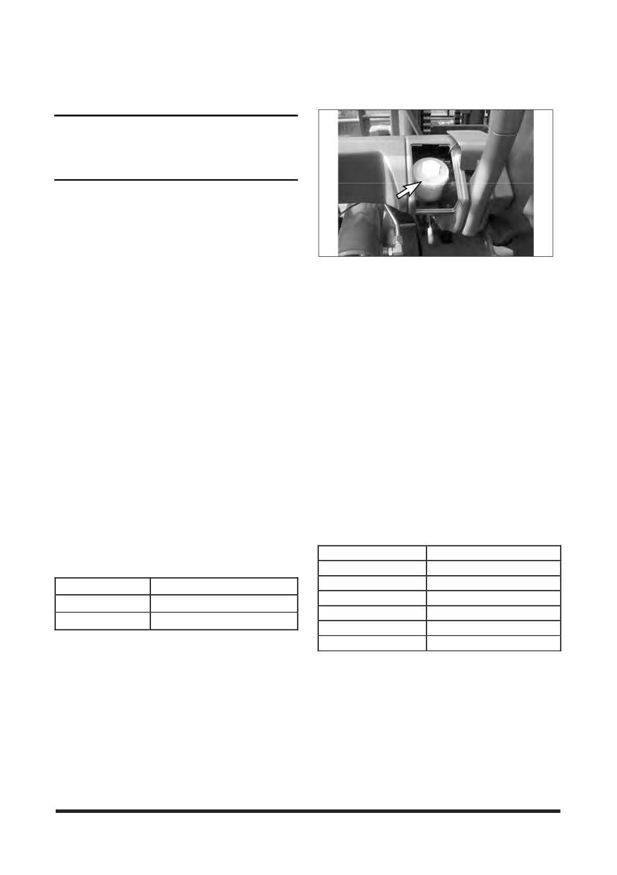
Maintenance Section
Transmission Oil (TDTO)
Brake Fluid
NOTICE
This oil is formulated for transmissions and drive
trains only, and should not be used in engines.
Shortened engine life will result.
NOTE: MuIti-grade oils are not blended by
CROWN for use in transmissions. Multi-
grade oils which use high molecular weight
polymers as viscosity index improvers lose
their viscosity effectiveness by permanent
and temporary shear of the viscosity index
improver and therefore, are
not
recommended for transmission and drive
train compartments.
Oil Cooled Disc Brake Only
Use heavy duty hydraulic brake fluid certified by oil
NOTE: Failure to follow this recommendation can
supplier to meet the latest version of following
cause shortened transmission life due to
classifications.
material
incompatibility,
inadequate
frictional requirements for disk materials
ISO 6743/4
HM
and/or excessive gear wear.
AFNOR NFE 48-603
HM
Select the oil that meets the following specification.
DIN 51524 TEIL 2
H-LP
HAGGLUNDS DENISON
HFO-HF2
GM DEXRON III
CINCINNATI
P68,69,70
FORD MERCON V
Viscosity : ISO VG32
Drive Axle Oil
Brake reservoir oils that have passed the Vickers
NOTE: Failure to follow the recommendation will
vane pump test (35VQ25). These oils should have
cause shortened life due to excessive gear
antiwear, antifoam, antirust and antioxidation
wear.
additives for heavy duty use as stated by the oil
supplier. ISO viscosity grade of 32 would normally
Oil Cooled Disc Brake (OCDB)
be selected.
Select oil that meets below specifications.
The following products are authorised for use.
: Universal Transmission Tractor Oil (UTTO)
Supplier
Product Name
The following UTTO products are authorised for use.
TOTAL
AZOLLAZS
SHELL
TELLUS
Supplier
Product Name
MOBIL
DTE20S’
TOTAL
TRANSMISSION MP
CALTEX
RANDO HD
MOBIL
MOBILFLUID 424
ESS
NOTO H
CASTROL
HYSPIN AWS
Lubricating Grease (MPGM)
Use Multipurpose Molybdenum Grease (MPGM) for
all lubrication points. If MPGM grease can not be
used, a multipurpose type grease which contains
3% to 5% molybdenum disulfide can be used.
NLGI No.2 grade is suitable for most temperatures.
Use NLGI No.1 or No.0 grade for extremely low
temperature.
-112-
Maintenance Section
Lubricant Viscosities and Refill Capacities
Refill Capacities
Lubricant Viscosities
Lubricant Viscosities
Refill Capacities-(Approximate)
for Ambient (Outside) Temperatures
U.S.
Compartment
Oil
°C
°F
Compartment or System
Liters
Gal.
or System
Viscosities
Min
Max
Min
Max
SAE
Engine Crankcase
-30
+30
-22
+86
4.3
1.1
5W30
w/Filter LP
Engine
SAE 10W30
-20
+30
-4
+86
Crankcase
SAE 5W40
-30
+40
-22
+104
Cooling System
(LP) and
w/Coolant Recovery
19.0
5.0
SAE 10W40
-20
+40
-4
+104
Lift Chains
Bottle LP
SAE 15W40
-10
+40
+14
+104
API SJ
SAE 15W50
-10
+50
+14
+122
SAE 20W50
-5
+50
+23
+122
Power Shift Transmission
13.0
3.4
Power Shift
Hydraulic & Power
Transmission
DEXRON III
-20
+50
-4
+122
73.0
19.3
Steering System
DEXRON III
ISO VG32
-20
+30
-4
+86
Drive Axle
Disc Brake (OCDB)
14.0
3.7
Hydraulic and
Power Steering
Brake Reservoir (Only for OCDB)
0.6
0.16
ISO VG46
-10
+40
+14
+104
System
ISO 6743/4 HM
ISO VG68
0
+50
+32
+122
Disc
Drive
Brake
Axle
UTTO
-20
+80
-4
+176
(OCDB)
Housing
UTTO
ISO VG32
-20
+30
-4
+86
Brake Reservoir
(Only for OCDB)
ISO VG46
-10
+40
+14
+104
ISO 6743/4HM
ISO VG68
0
+50
+32
+122
The SAE grade number indicates the viscosity of oil.
A proper SAE grade number should be selected
according to ambient temperature.
-113-
Maintenance Section
Transmission Oil Level - Check
125
Maintenance Intervals
Hydraulic Oil Level - Check
126
Drive Axle Oil Level - Check
126
Brake Oil Level - Check
126
NOTICE
Users should be familiar with the requirements for
First 50 - 100 Service Hours or a Week
inspection and maintenance of lift trucks as provided
by Australian Standard AS2359.
Transmission Oil, Oil Filter & Strainer - Clean,
Change
128
Drive Axle Oil - Check, Clean, Change
130
Parking Brake - Test, Adjust
131
NOTICE
Never exceed the Maintenance Intervals specified in
Every 250 Service Hours or Monthly
the manual. Defects and/or damage to the important
functional components may be resulted in.
Engine Oil & Filter - Change
133
Every 500 Service Hours or 3 Months
NOTICE
Air Intake System - Check, Clean
134
All maintenance and repair, except Every 10 Service
Tilt Cylinders - Check, Adjust, Lubricate
136
Hours or Daily, on the lift truck must be performed
Mast Hinge Pins - Lubricate
137
by qualified and authorised personnel only.
Crosshead Rollers - Inspect
137
Carriage Side Rollers Thrust (If Equipped) -
Lubricate
137
Carriage Sideshifter (If Equipped) - Lubricate
137
NOTICE
Mast, Carriage, Lift Chains, & Attachments - Check,
Careless disposal of waste oil can harm the
Lubricate
138
environment and can be dangerous to persons.
Carriage Side Rollers - Lubricate
138
Always dispose of waste oil to authorised personnel
Parking Brake - Test, Adjust
139
only.
Circulation Pump Belt (OCDB & LP Engine Only. If
Eguipped) - Check, Adjust
139
Drive Axle Oil & Strainer (OCDB Only) - Check,
Clean, Change
139
When Required
Horn & Lights (If Equipped) - Check
140
Inspect Vacuum Lines and Fittings (LP Engine only)
Test Fuel System for Leaks (LP Engine Only)
118
................................................................................. 140
Seat, Hood Latch & Support Cylinder - Check,
Fuel Trim Valve(FTV) Inspection (PSI Engine only)
Lubricate
118
................................................................................. 141
Fuses, Bulbs & Circuit Breaker - Change, Reset
Inspect Electrical System (LP Engine only)
141
.................................................................................119
Overhead Guard - Inspect
141
Fuse & Relay (LP Engine Only)
120
Steer Suspension - Inspect
141
Circuit Breaker
120
Steering Mechanism - Check, Lubricate
142
Carriage Roller Extrusion - Check, Adjust
121
Wheel Bolts and Nuts - Inspect
142
Battery Terminal - Clean, Inspect
121
Every 1000 Service Hours or 6 Months
Every 10 Service Hours or Daily
Air Intake System - Change
143
Inspect Engine for Fluid Leaks
122
Inspect Coolant Hoses (LP Engines Only)
143
Engine Oil Level - Check
122
LP Regulator/Converter Inspection (LP Engine Only)
Coolant Level - Check, Clean
122
................................................................................. 143
Air Cleaner Indicator - Check
123
Fuel Lines & Fittings - Check
144
Walk - Around Inspection - Inspect
124
Inspect Mixer Assembly (LP Engine Only)
144
Mast Channels - Lubricate
125
Inspect Throttle Assembly (LP Engine Only)
144
-114-
Maintenance Section
Hydraulic Return Filter - Change
144
Air Breather - Change
144
Transmission Oil, Oil Filter & Strainer - Clean,
Change
144
Lift Chains - Test, Check, Adjust
145
Universal Joint - Inspect
147
Every 1500 Service Hours or 9 Months
Drive Axle Oil (Shoe Brake Only) - Check, Clean,
Change
148
Inspect Ignition System (LP Engine Only)
148
Replace Spark Plugs (LP Engine Only)
148
Replace LP Fuel Filter Element (LP Engine Only)
.................................................................................149
Fuel Filter (LP Engine Only)
149
Testing Fuel Lock-off Operation (LP Engine Only)
.................................................................................150
Every 2000 Service Hours or Yearly
Steer Wheel Bearings -Reassemble
151
Cooling System - Clean, Change
152
Fork - Inspect
153
Every 2500 Service Hours or 15 Months
Hydraulic Oil - Check, Clean, Change
155
Inspect Battery System
155
Checking the TMAP Sensor (LP Engine Only)
156
Inspect for Intake Leaks (LP Engine Only)
156
Replace PCV Valve and breather element - Change
(LP Engine Only)
156
Replace Oxygen Sensor (PSI Engine)
156
Environment Protection
Environment Protection
157
-115-
Maintenance Section
Quick Reference to Maintenance Schedule
FIRST
EVERY
ITEMS
SERVICES
PAGE
Air Breather
Change
144
O
Air Cleaner Indicator
Check
123
O
Air Intake System
Change
143
O
Air Intake System
Check, Clean
134
O
Battery Terminal
Clean, Inspect
121
O
Brake Oil Level
Check
126
O
Carriage Roller Extrusion
Check, Adjust
121
O
Carriage Side Rollers
Lubricate
138
O
Carriage Side Rollers Thrust (If Equipped)
Lubricate
137
O
Carriage Sideshifter (If Equipped)
Lubricate
137
O
Checking the TMAP Sensor (LP Engine
156
O
Only)
Circuit Breaker
120
O
Circulation Pump Belt (OCDB & LP Engine
Check, Adjust
139
O
Only. If Eguipped)
Coolant Level
Check, Clean
122
O
Cooling System
Clean, Change
152
O
Crosshead Rollers
Inspect
137
O
Check, Clean,
Drive Axle Oil
130
O
Change
Check, Clean,
Drive Axle Oil & Strainer (OCDB Only)
139
O
Change
Check, Clean,
Drive Axle Oil (Shoe Brake Only)
148
O
Change
Drive Axle Oil Level
Check
126
O
Engine Oil & Filter
Change
133
O
Engine Oil Level
Check
122
O
Fork
Inspect
153
O
Fuel Filter (LP Engine Only)
149
O
Fuel Lines & Fittings
Check
144
O
Fuel Trim Valve(FTV) Inspection (PSI
141
O
Engine only)
Fuse & Relay (LP Engine Only)
120
O
Fuses, Bulbs & Circuit Breaker
Change, Reset
119
O
Horn & Lights (If Equipped)
Check
140
O
Check, Clean,
Hydraulic Oil
155
O
Change
Hydraulic Oil Level
Check
126
O
Hydraulic Return Filter
Change
144
O
Inspect Battery System
155
O
Inspect Coolant Hoses (LP Engines Only)
143
O
-116-
Maintenance Section
Quick Reference to Maintenance Schedule
FIRST
EVERY
ITEMS
SERVICES
PAGE
Inspect Electrical System (LP Engine only)
141
O
Inspect Engine for Fluid Leaks
122
O
Inspect for Intake Leaks (LP Engine Only)
156
O
Inspect Ignition System (LP Engine Only)
148
O
Inspect Mixer Assembly (LP Engine Only)
144
O
Inspect Throttle Assembly (LP Engine Only)
144
O
Inspect Vacuum Lines and Fittings (LP Engine
140
O
only)
Test, Check,
Lift Chains
145
O
Adjust
LP Regulator/Converter Inspection (LP Engine
143
O
Only)
Mast Channels
Lubricate
125
O
Mast Hinge Pins
Lubricate
137
O
Check,
Mast, Carriage, Lift Chains, & Attachments
138
O
Lubricate
Overhead Guard
Inspect
141
O
Parking Brake
Test, Adjust
131,139
O
O
Replace LP Fuel Filter Element (LP Engine
149
O
Only)
Replace Oxygen Sensor (PSI Engine Only)
156
O
Change (LP
Replace PCV Valve and breather element
156
O
Engine Only)
Replace Spark Plugs (LP Engine Only)
148
O
Check,
Seat, Hood Latch & Support Cylinder
118
O
Lubricate
Steer Suspension
Inspect
141
O
Steer Wheel Bearings
Reassemble
151
O
Check,
Steering Mechanism
142
O
Lubricate
Test Fuel System for Leaks (LP Engine Only)
118
O
Testing Fuel Lock-off Operation (LP Engine
150
O
Only)
Check, Adjust,
Tilt Cylinders
136
O
Lubricate
Transmission Oil Level
Check
125
O
Transmission Oil, Oil Filter & Strainer
Clean, Change
128,144
O
O
Universal Joint
Inspect
147
O
Walk - Around Inspection
Inspect
124
O
Wheel Bolts and Nuts
Inspect
142
O
-117-
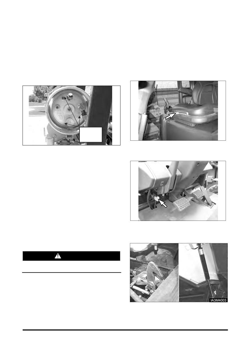
Maintenance Section
When Required
You must read and understand the warnings and instructions contained in the Safety section of this manual,
before performing any operation or maintenance procedures.
Test Fuel System for Leaks (LP
Seat, Hood Latch & Support
Engine Only)
Cylinder - Check, Lubricate
Check
Points
1. Check the operation of the seat adjuster rod. Make
sure that the seat slides freely on its track. Lightly oil
1. Obtain a leak check squirt bottle or pump spray
the seat slider tracks if necessary.
bottle.
2. Fill the bottle with an approved leak check solution.
3. Spray a generous amount of the solution on the fuel
system fuel lines and connections, starting at the
storage container.
4. Wait approximately 15-60 seconds then perform a
visual inspection of the fuel system. Leaks will
cause the solution to bubble.
5. Repair any leaks before continuing.
6. Crank the engine through several revolutions. This
will energize the fuel lock-off and allow fuel to flow to
the pressure regulator/converter. Apply additional
leak check solution to the regulator/converter fuel
connections and housing. Repeat leak inspection as
2. Push the lever down to raise the hood and seat
listed above.
assembly. Make certain the support cylinder will
hold the hood open.
7. Repair any fuel leaks before continuing.
WARNING
Prior to any service or maintenance activity, Test
Fuel System for Leaks
3. Lightly oil the hood latch mechanism and the rod for
the hood support cylinder.
-118-
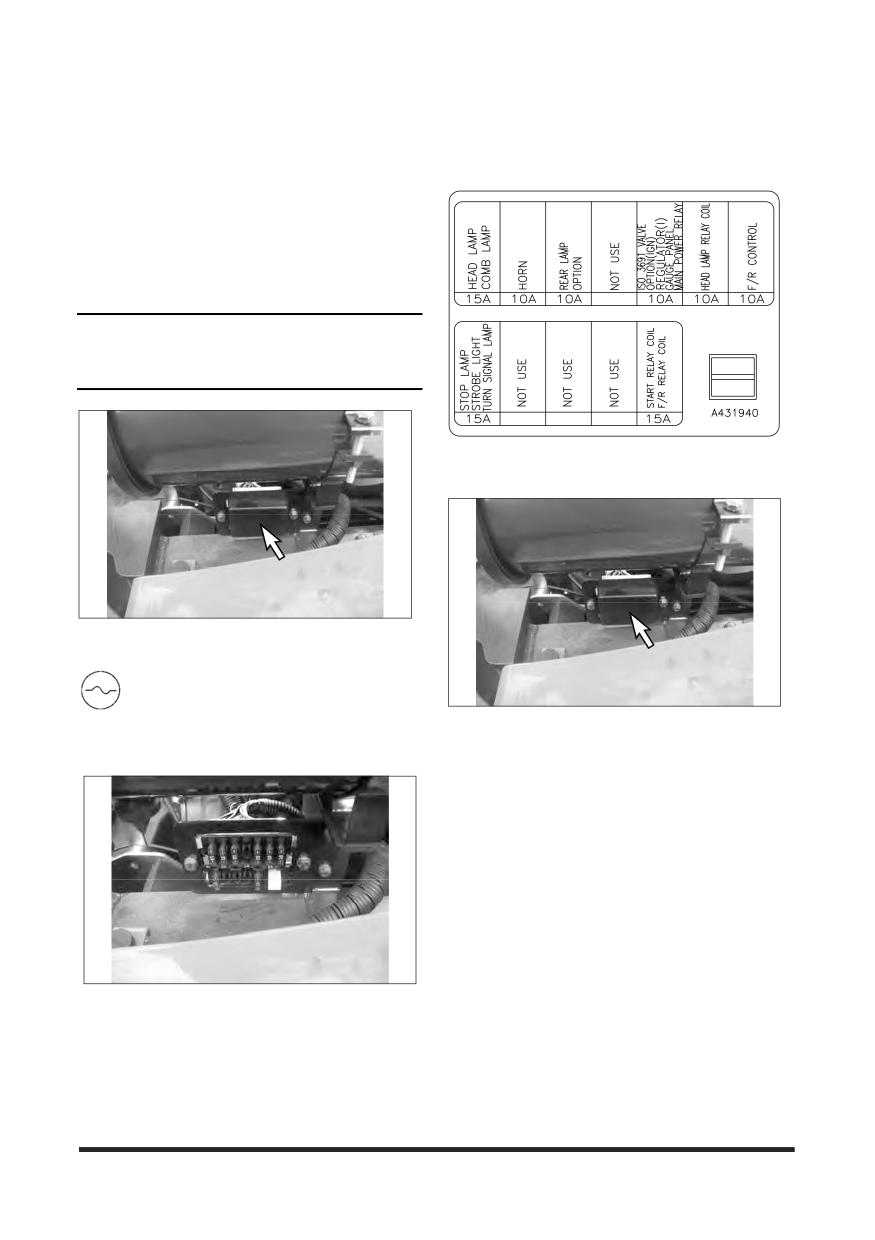
Maintenance Section
Fuses, Bulbs & Circuit Breaker -
Change, Reset
Gas
Fuses
NOTE: If a fuse filament separates, use only the
same type and size fuses for replacement.
If the filament in a new fuse separates,
have the circuits and instruments checked.
NOTICE
Always replace fuses with ones of the correct
ampere rating.
Fuse Box (Close)
Remove the front cover from the fuse box. The
fuses are located under the air cleaner.
Fuse - Protects an electrical circuit from an
overload. Opens (filament separates) if an
overload occurs.
Typical Example
Fuse Box (Open)
Fuses are identified as follows :
1. Horn - 10 A
2. Head Lamp ,Clearance Lamp, Tail Lamp - 15 A
3. Lamp Relay Coil, Fwd/Rev. Solenoid, Rear Lamp
Relay & Back-up Lamp/Alarm - 15 A
4. Instrument Panel, Hour Meter, Preheat Controller,
Fuel Shut off Solenoid - 15 A
5. Stop Lamp, Turn Signal Lamp, Strobe Lamp - 15 A
6. Starter Relay - 10 A
Typical Example
-119-
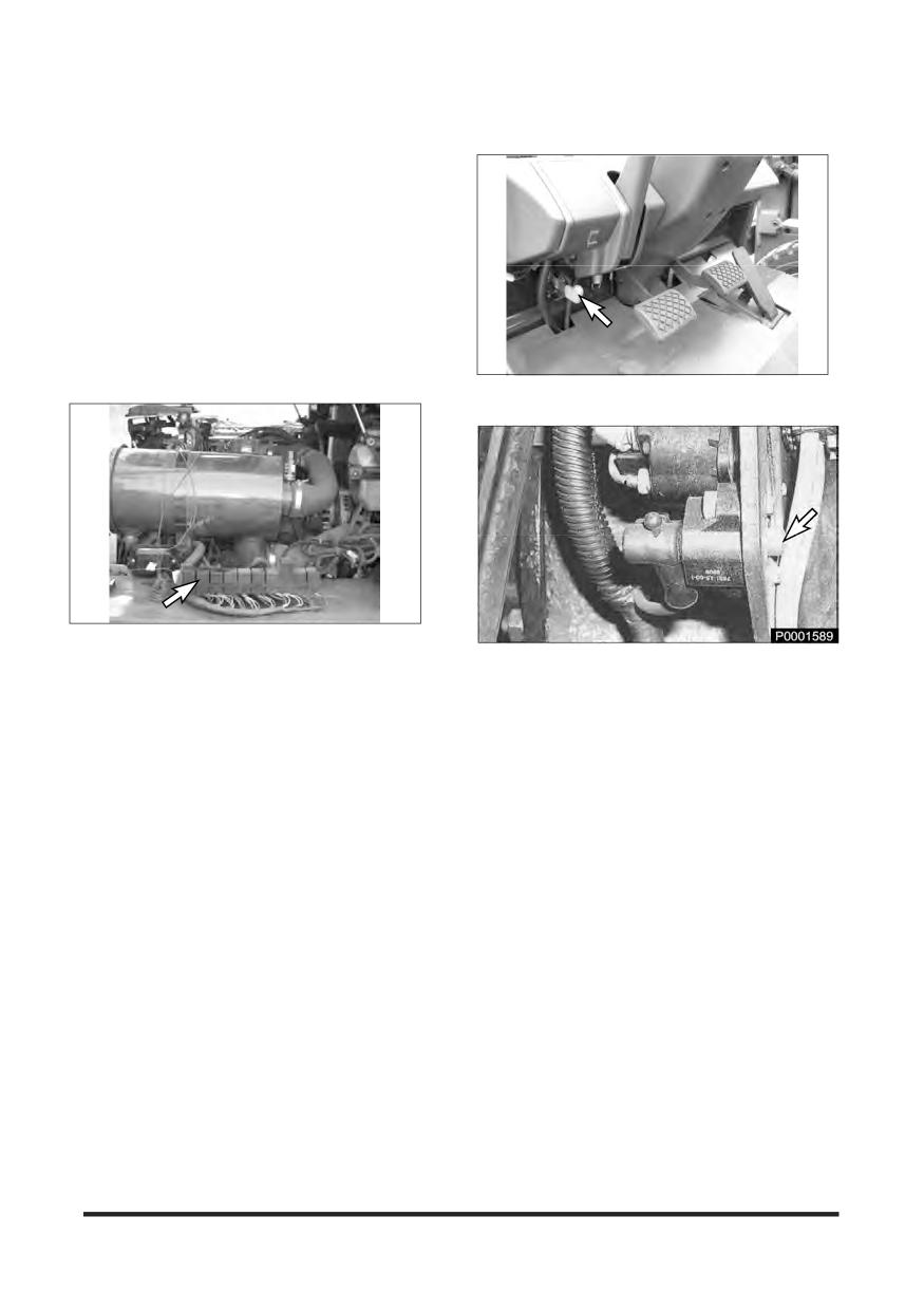
Maintenance Section
Bulbs
Circuit Breaker
Bulbs are identified as follows:
[ LP Gas Engine ]
1. Bulb - head lamp halogen (12V - 35W)
*2. Bulb - back up (12V - 8W)
*3. Bulb - turn signal (12V - 23W)
*4. Bulb - stop & tail (12V - 23/8W)
*Optional lamp or light
Fuse & Relay (LP Engine Only)
1. Raise the hood and seat assembly. Make sure the
support cylinder securely holds the hood open.
Typical Example LP Engine Truck
2. The main circuit breaker is located on the rear of the
support for the controls.
NOTE: To reset circuit breakers push in on the
button. The button should stay in if the
breaker is reset. If the button will not stay in,
or comes out shortly after reset, have the
circuits checked.
-120-
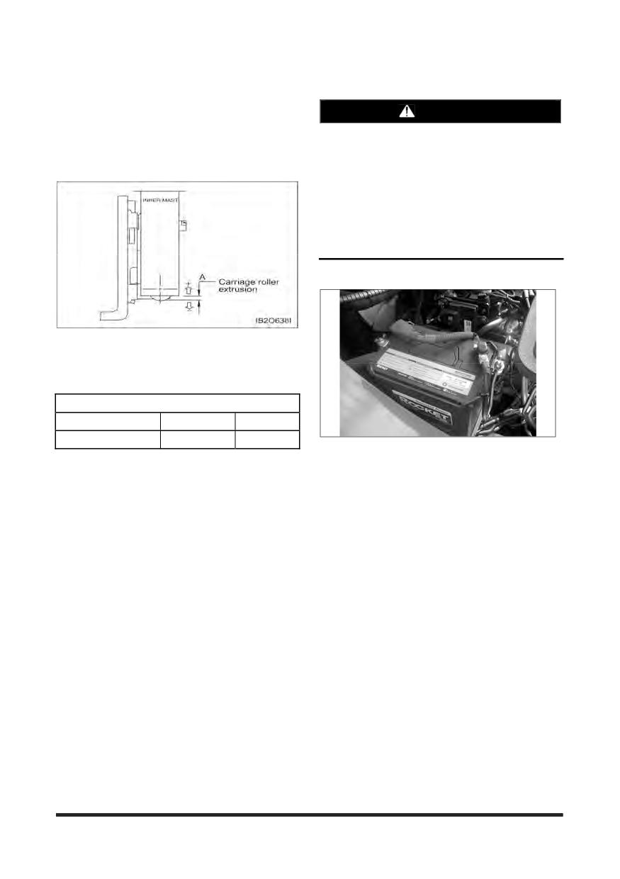
Maintenance Section
Carriage Roller Extrusion - Check,
Battery Terminal - Clean, Inspect
Adjust
WARNING
1. Set the mast vertical.
2. Lower the carriage completely.
Batteries give off flammable fumes that can
explode.
3. On full free lift and full free triple lift models, the
bottom of the inner mast must be flush with the
Do not smoke when observing the battery
electrolyte levels.
Electrolyte is an acid and can cause personal
injury if it contacts skin or eyes.
Always wear protective glasses when working
with batteries.
LP Engine - 12V X 1
5. Measure the distance from the bottom of the inner
upright to the bottom of carriage bearing.
6. The measurement (A) must be as follows in Chart
below.
Height of carriage roller extrusion (A) [unit : mm]
STD mast
FF mast
FFT mast
-7
43
43
Typical Example
LP Engine Truck
1. Clean the top of the battery and terminals.
2. Check terminals for corrosion. Coat terminals with
heavy grease.
3. Ensure the battery terminal is firmly tightened and
rubber cap is installed.
-121-
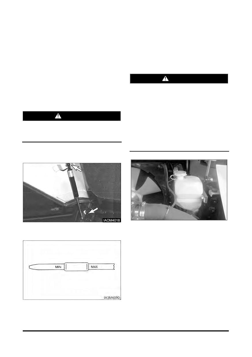
Maintenance Section
Every 10 Service Hours or Daily
You must read and understand the warnings and instructions contained in the Safety section of this manual,
before performing any operation or maintenance procedures.
Coolant Level - Check, Clean
Inspect Engine for Fluid Leaks
1. Start the engine and allow it to reach operating
Check Coolant Level
temperatures.
WARNING
2. Turn the engine off.
3. Inspect the entire engine for oil and/or coolant leaks.
At operating temperature, the engine coolant is
hot and under pressure.
4. Repair as necessary before continuing.
Steam can cause personal injury.
Engine Oil Level - Check
Check the coolant level only after the engine has
been stopped and the filter cap is cool enough
WARNING
to touch with your bare hand.
Hot oil and components can cause personal
Remove the filter cap slowly to relieve pressure.
injury. Do not allow hot oil or components to
contact skin.
Cooling system conditioner contains alkali.
Avoid contact with the skin and eyes to prevent
personal injury.
Park the lift truck level, with the forks lowered,
parking brake applied, transmission in NEUTRAL
and the engine stopped.
1. Observe the coolant level with engine cold. Maintain
1. Raise the hood and seat assembly. Make certain
coolant level to the proper line on expansion bottle.
the support cylinder securely holds the hood open.
If the expansion bottle has no coolant, it will be
necessary to check coolant at the radiator filter neck.
2. Remove the radiator cap. Fill radiator to the top of
the filter neck. Inspect radiator cap. Replace if
damaged. Install the radiator cap.
2. The oil level should be close as possible to upper
point of the oil dip stick. Do not refill more than
upper point.
-122-
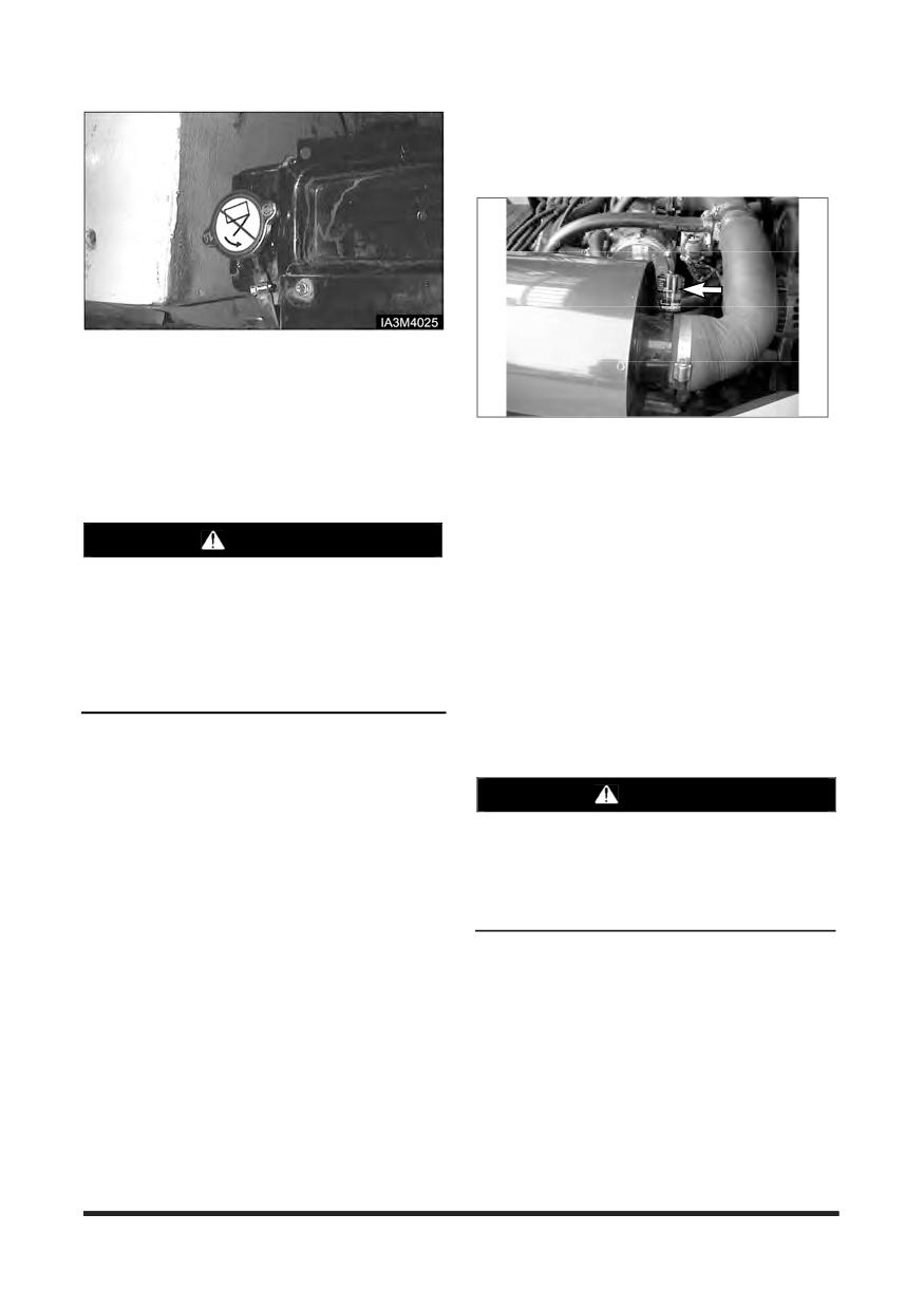
Maintenance Section
Air Cleaner Indicator - Check
Checking Service Indicator
3. Start and run the engine to stabilise the coolant level
in the filter neck. If low add coolant until it reaches
the top of the filter neck. Install the radiator cap.
Observe coolant level in the expansion bottle. If
necessary, add coolant to bring the coolant to the
Typical Example
LP Engine Truck
appropriate line on the expansion bottle.
4. Stop the engine.
1. Observe the air cleaner service indicator.
5. Inspect the cooling system for leaks, hose cracks or
2. Service the air cleaner when the RED band in the
loose connections.
service indicator, lock in the visible position. See
topic, “Air Intake System - Check, Clean” in “Every
WARNING
250 Service Hours or Monthly”.
NOTE: Service the element more frequently, as
Pressure air can cause personal injury.
required, in severe dust or lint conditions.
Also, service it more frequently where the
When using pressure air for cleaning, wear a
protective face shield, protective clothing and
operator is required to wear a respirator.
protective shoes.
3. Close hood and seat assembly.
Maximum air pressure must be less than 205
kPa (30 psi) for cleaning purposes.
Inspect Acceleration Pedal
6. Blow any dust and lint from the radiator fins.
Operation(PSI Engine)
1. Verify foot pedal travel is smooth without sticking.
WARNING
When the acceleration pedal harness is
connected or disconnected, should be worked
key OFF condition.
If not, occurred malfunction, can cause the
personal injury.
Inspect Engine for Exhaust Leaks
1. Start the engine and allow it to reach operating
temperatures.
2. Perform visual inspection of exhaust system.
3. Repair any/all leaks found.
-123-
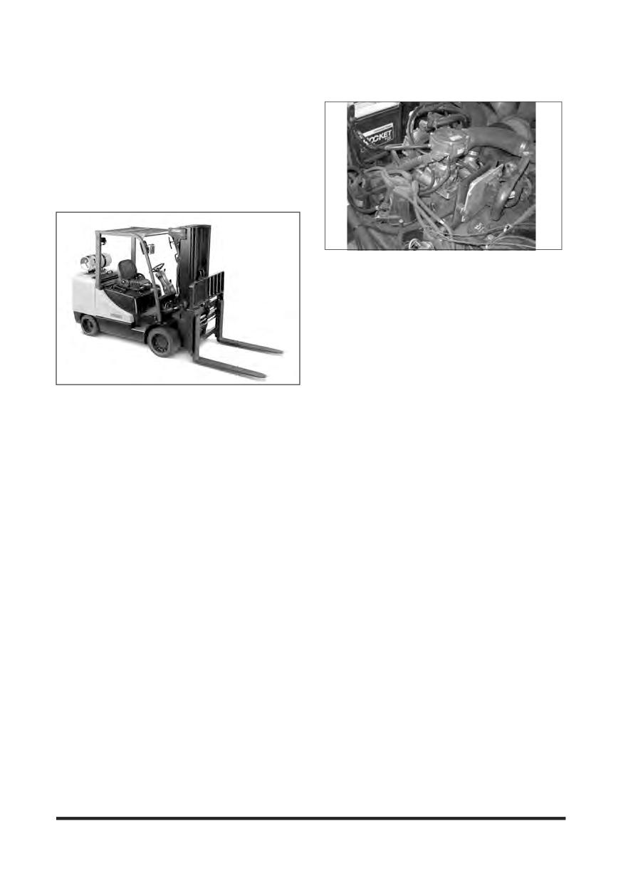
Maintenance Section
Walk - Around Inspection - Inspect
For maximum service life of the lift truck, make a
thorough walk-around inspection.
Look around and under the truck for such items as
loose or missing bolts, debris or dirt buildup, fuel, oil
or coolant leaks and cut gouged tyres.
Have any repairs made and debris removed, as
needed.
Typical Example
LP Engine Truck
8. Inspect the cooling system for leaks, worn hoses
and debris buildup.
9. Inspect engine compartment for oil, coolant and fuel
leaks.
10. Inspect the forks.
Visually inspect forks for cracks, especially in the
heel section, around the mounting brackets, and all
weld areas.
1. Inspect the tyres and wheels for cuts, gouges,
Inspect for broken or jagged fork tips, bent or
foreign objects, inflation pressure and loose or
twisted blades and shanks.
missing bolts.
Make sure positioning lock is in place and working.
Lock the forks in position before using the truck.
2. Inspect the mast and lift chains for wear, broken
See Step 7 of “ Forks ” in “ Every 2000 Service
links, pins and loose rollers.
Hours or Yearly ”
3. Inspect the hydraulic system for leaks, worn hoses
Remove all defective forks from service.
or damaged lines.
4. Look for transmission and differential leaks on the lift
truck and on the ground.
5. Inspect the operator’s compartment for loose items
and cleanliness.
6. Inspect the instrument panel for broken gauges and
indicator lights.
7. Test the horn and other safety devices for proper
operation.
-124-
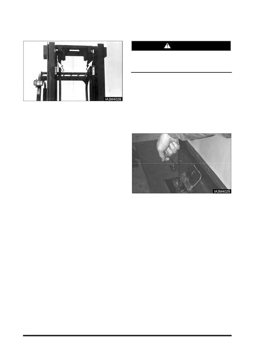
Maintenance Section
Mast Channels - Lubricate
Transmission Oil Level - Check
WARNING
Hot oil and components can cause personal
injury. Do not allow hot oil or components to
contact skin.
1. Start and operate the lift truck until the engine
reaches normal operating temperature.
2. Park the lift truck level with the forks lowered,
parking brake applied and the transmission controls
in NEUTRAL.
The channels on the roller-type mast require a
3. With the brake applied and the engine at low idle,
break-in period. Apply a light film of lubricant on the
shift the directional control lever to forward and then
channels where the rollers ride. This will prevent
to reverse, to fill the clutches.
metal peel until the rollers set a pattern.
4. Shift the direction control lever to the NEUTRAL
position.
5. Open the access door in floor plate.
6. Remove the dipstick/filter cap. Observe the oil level.
7. Maintain the oil level between the Min and Max
marks on the dipstick/filter cap.
When the oil temperature is 40°C approximately,
the cold side mark on the dipstick is applicable.
When the oil temperature is 80°C approximately,
the hot side mark on the dipstick is applicable.
8. Close the access door in floor plate.
9. Stop the engine.
-125-
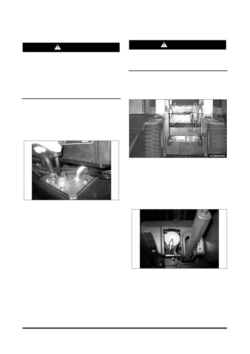
Maintenance Section
Drive Axle Oil Level - Check
Hydraulic Oil Level - Check
WARNING
WARNING
Hot oil and components can cause personal
At operating temperature, the hydraulic tank is
injury. Do not allow hot oil or components to
hot and under pressure.
contact skin.
Hot oil can cause burns.
Park the lift truck on a level surface. Apply the
Remove the filter cap only when the engine is
parking brake. The engine is at the low idle. Place
stopped, and the cap is cool enough to touch
with your bare hand. Remove the filter cap
the directional control level in NEUTRAL.
slowly to relieve pressure.
1. Operate the lift truck for a few minutes to warm the
oil. Park the lift truck on a level surface, with the
forks lowered, mast tilted back, parking brake
engaged, transmission in NEUTRAL and the engine
stopped.
2. Raise the hood and seat assembly. Make sure the
air lift cylinder securely holds the hood open.
1. Lift the carriage high enough to access the drive
axle housing oil level plug and fill plug.
2. Put blocks under the carriage.
Brake Oil Level - Check
3. Remove the dipstick/ filter cap. Maintain the oil level
to the FULL mark on the breather/dip stick.
The brake reservoir is located on the left side of the
steering column.
1. Remove the filler cap.
2. Maintain the brake fluid level to the fluid level mark
on the brake system reservoir.
3. Clean and install the filler cap
-126-

Maintenance Section
Oil Cooled Disc Brake (OCDB) Type
1. Remove the dip stick/filter cap. Observe the oil level.
2. Maintain the oil level between lower mark and upper
mark on the dip stick/filter cap.
3. Install the dip stick/filter cap
-127-
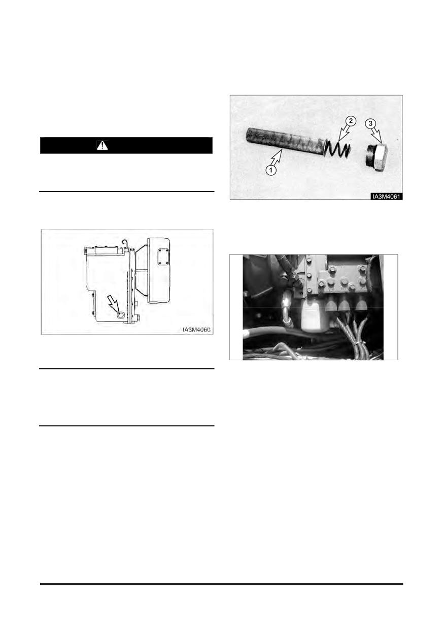
Maintenance Section
First 50 - 100 Service Hours or a Week
You must read and understand the warnings and instructions contained in the Safety section of this manual,
before performing any operation or maintenance procedures.
Transmission Oil, Oil Filter &
Strainer - Clean, Change
WARNING
Hot oil and components can cause personal
injury. Do not allow hot oil or components to
contact skin.
Park the lift truck level, with the forks lowered,
parking brake engaged, transmission in NEUTRAL
2. Wash the strainer (screen) ①, spring ② and drain
and the engine stopped.
plug ③ in clean, nonflammable solvent. Dry and
install the strainer, spring and drain plug.
3. Raise the hood and seat assembly.
1. Remove the drain plug, spring and strainer. Allow
the oil to drain.
4. Remove and discard the oil filter. Wipe off the filter
NOTICE
base. Make sure all of the old seal is removed.
Careless disposal of waste oil can harm the
5. Put a small amount of clean oil on the seal on the
environment and can be dangerous to persons.
new filter. Install the filter by hand. When the filter
contacts the base, tighten it an additional 3/4 turn.
Always dispose of waste oil to authorised and
licensed personnel only.
6. Close the hood and seat assembly.
-128-
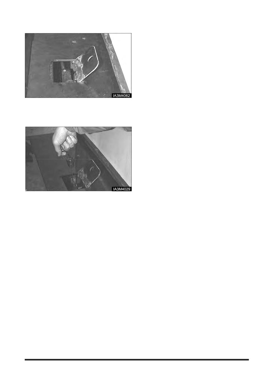
Maintenance Section
7. Open the access door in the floor plate.
8. Remove the dipstick/filter cap. Fill the transmission
with oil. See “Refill Capacities” Install the dipstick/
filter cap.
9. Start the engine.
10. With the service brake applied and engine at low
idle, shift the transmission to forward and reverse to
fill the clutches.
11. Shift the transmission into NEUTRAL. Apply the
parking brake.
12. Remove the dipstick/ filter cap.
13. Maintain the oil level between the Min and Max
marks on the dipstick/filter cap.
When the oil temperature is 40°C approximately,
the cold side mark on the dipstick is applicable.
When the oil temperature is 80°C approximately,
the hot side mark on the dipstick is applicable.
14. Check for oil leaks at the filter and drain plug.
15. Stop the engine.
-129-
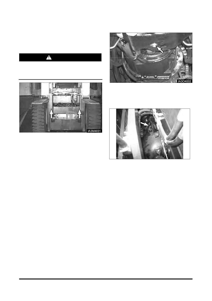
Maintenance Section
Oil Cooled Disc Brake (OCDB) Type
Drive Axle Oil - Check, Clean,
Change
Park the lift truck on a level surface, parking brake
applied, transmission in neutral.
WARNING
Hot oil and components can cause personal
injury. Do not allow hot oil or components to
contact skin.
1. Remove drain plug. Allow the oil to drain into a
suitable container. Clean the magnetic drain plug.
Check O-ring seal and replace if necessary.
2. Install the drain plug.
1. Lift the carriage high enough to access the drive
axle housing fill plug with breather.
2. Block the bottom of the mast with a block of wood to
hold the carriage in the raised position.
3. Turn the ignition switch OFF.
3. Remove the dip stick/filter cap. Fill the drive axle
housing with oil. See “Lubricant Specification - Drive
Axle Oil” and “Refill Capacity”
4. Start the lift truck. With the engine at low idle, place
the directional control lever to the NEUTRAL.
5. Maintain the oil level between lower mark and upper
mark on the dip stick/filter cap.
6. Install the dip stick/filter cap.
-130-
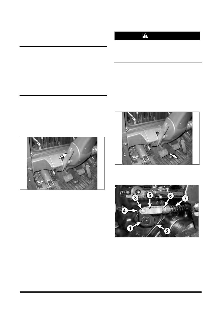
Maintenance Section
Parking Brake - Test, Adjust
WARNING
Parking Brake Testing
To prevent personal injury, the operator MUST
NOTICE
be ready to use the service brake if the parking
OSHA requires the parking brake to hold the lift
brake is not adjusted correctly and the lift truck
truck, with capacity load, on a 15% grade.
starts to move.
Testing requires a test load equal to the capacity of
the truck and a 15% grade.
Parking Brake Adjusting
If the maximum grade in the workplace is less than
its capacity, use the Parking Brake inspection
1. Park the lift truck on a level surface, lowered the
procedure covered in ‘Inspection from Operator’s
forks, shift the transmission to NEUTRAL and
Seat, Engine On’ in “Every 10 Service Hours or
shut OFF the engine and block the wheels
Daily” section.
securely.
1. Pick up capacity load and drive over to a 15%
2. Chock the lift truck's tyres to prevent unintentional
grade.
movement.
2. Drive forward up the 15% grade. Halfway up the
grade, stop the lift truck with its service brakes.
3. Engage the parking brake and slowly release the
service brake.
3. Remove the floor mat and floor plate.
4. Make sure the parking brake lever is released.
4. Engage the parking brake and shift the
transmission to NEUTRAL. Slowly release the
service brakes.
5. The parking brake adjustment is proper if it holds
the lift truck on the grade. The parking brake
needs adjusting if it does not hold the lift truck on
the grade.
6. If the lift truck starts to move in reverse down the
grade with the parking brake engaged, stop it with
the service brakes, disengage the parking brake
5. Make sure the brake lever (1) is held against stop
and reverse slowly down the grade controlling
pin (2). If the brake lever (1) is held against the
your speed with the service brakes.
stop pin (2), go to step 7. If the brake lever (1) is
NOT held against the stop pin (2), go to step 6.
-131-
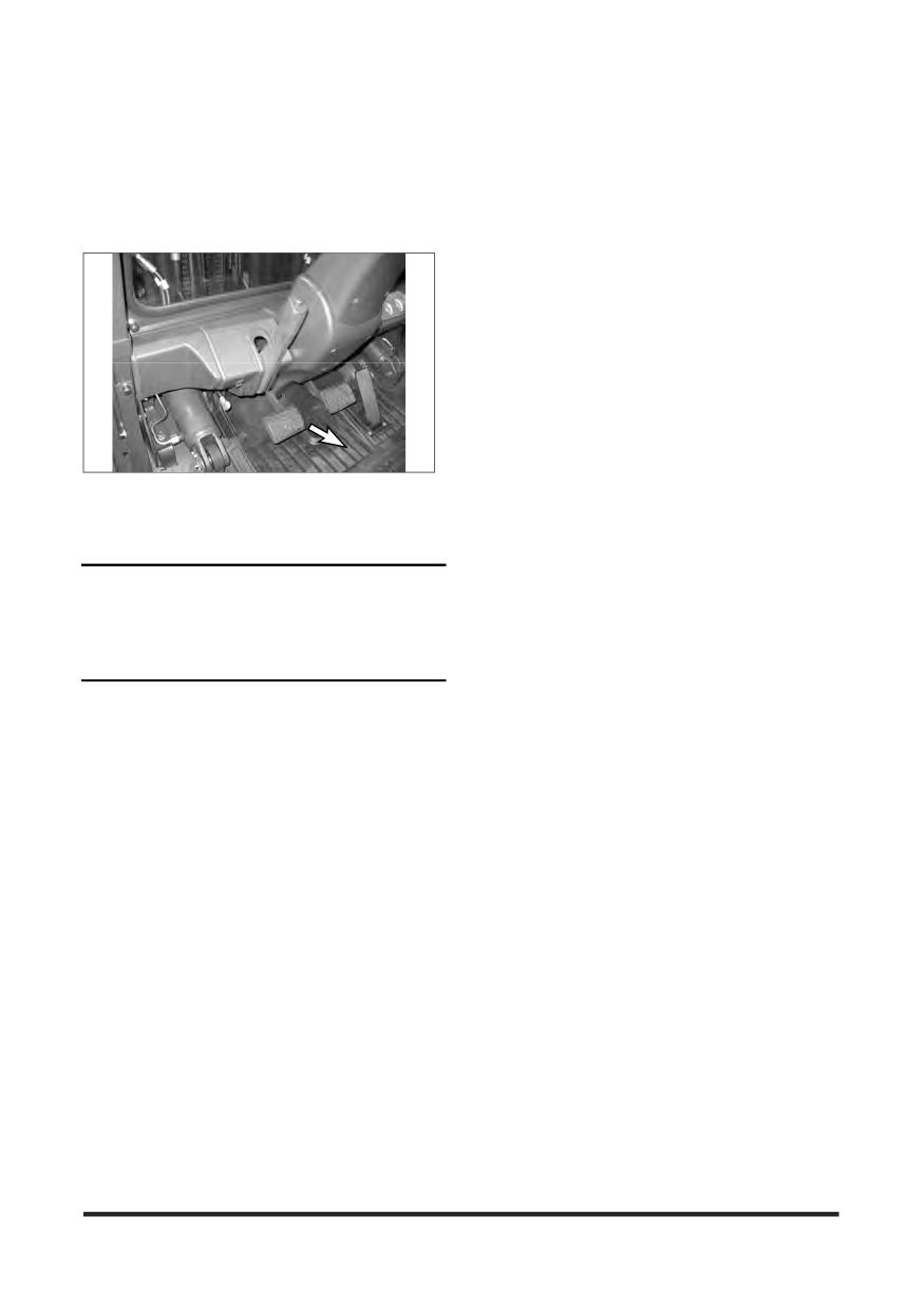
Maintenance Section
6. Remove the pin (3) and the cotter pin (4). Tighten
the nut (6) to compress the spring (7) further and
pull downward and turn the clevis (5) until the pin
(3) fits into the brake lever when the lever (1) is
held against the stop pin (2). Then install the pin
(3) and the cotter pin (4) and return the nut (6) to
the clevis (5).
7. Loosen lock nut (5). Tighten screw (6) to 6 to 7
N•m (50 to 60 lb•in). Loosen the screw (6) 1 1/6
turns and tighten the lock nut (5).
NOTICE
Turn the adjustment screw (6) clockwise to tighten.
Turning the screw (6) too far counterclockwise could
allow parts to fall into the bottom of the transmission.
The transmission would than require disassembly to
remove the parts.
8. Reinstall the floor plate and floor mat.
9. Engage the parking brake, remove the tyre
chocks and test the parking brake. Refer to
‘Parking Brake Testing’ in the preceding section.
To Adjust
Park the lift truck level, with the forks lowered,
transmission in NEUTRAL, the engine stopped and
the wheels securely blocked.
1. Release the parking brake.
2. Turn the adjustment knob, clockwise to tighten the
brake.
3. Test the parking brake adjustment. Repeat the
adjustment procedure, if necessary.
-132-
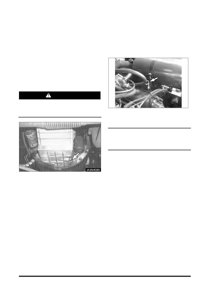
Maintenance Section
Every 250 Service Hours or Monthly
You must read and understand the warnings and instructions contained in the Safety section of this manual,
before performing any operation or maintenance procedures.
Engine Oil & Filter - Change
LP Engine Crankcase
1. Operate lift truck a few minutes to warm oil. Park the
lift truck with the forks lowered, parking brake
applied, transmission in neutral and the engine
stopped.
2. Raise rear of lift truck off ground and block securely.
WARNING
Hot oil and components can cause personal
injury. Do not allow hot oil or components to
contact skin.
13. Stop the engine and measure the oil level. Maintain
the oil level to the FULL mark on the dip stick.
14. Close hood and seat assembly.
NOTICE
Engine Oil Service hours can be extended to 500
hours by using CROWN supplied specific oil. Please
consult CROWN dealer about it.
3. Remove the crankcase drain plug and allow oil to
drain. Clean and install drain plug.
4. Raise the hood and seat assembly.
5. Remove and discard oil filter element.
6. Wipe sealing surface of oil filter element mounting
base. Make sure the entire old gasket is removed.
7. Before installing a new filter element, apply a small
amount of clean engine oil to the filter element
gasket.
8. Install the new filter element. When the gasket
contacts the base, tighten it 3/4 of a turn more. Do
not overtighten.
9. Raise the lift truck, remove the blocking and lower
the lift truck.
10. Fill the crankcase. See “Refill Capacities ”.
11. Start the engine and allow the oil to fill the filter and
passages.
12. Check for oil leaks.
-133-
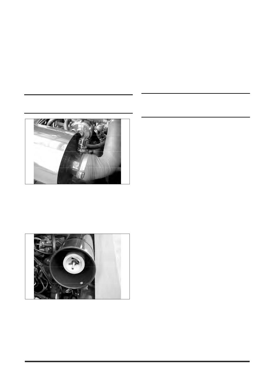
Maintenance Section
Every 500 Service Hours or 3 Months
You must read and understand the warnings and instructions contained in the Safety section of this manual,
before performing any operation or maintenance procedures.
cleaner and engine. Check intake hose for cracks,
Air Intake System - Check, Clean
damage and loose clamps. Tighten or replace parts
as necessary to prevent leakage.
Servicing Filter Element
NOTICE
NOTICE
Never service precleaner with the engine running.
Do not allow dirty air to enter the intake hose when
cleaning the inside of the air cleaner housing.
5. Check the air cleaner housing for loose latches.
6. Reset the air cleaner service indicator.
7. Install the air filter element.
8. Install the cover and tighten the cover latches.
9. Start the engine and observe the position of the
indicator. If the indicator shows RED after the
installation of the primary element, install another
clean or a new element or, replace the secondary
element. See topic, “Air Intake System - Change” in
Every 1000 Service Hours or 6 months section.
10. Stop the engine and close the hood and seat
Typical Example
LP Engine Truck
assembly.
Service the air cleaner when the red target in the
service indicator stays locked in the visible position
with the engine stopped.
1. To service the air cleaner, loosen the cover latches
and remove the cover.
Typical Example
LP Engine Truck
2. Rotate the element slightly to separate it from its
base and remove it from the air cleaner housing.
3. Clean and inspect the element or replace with a
new element. See topic, “Cleaning Primary Filter
Element”.
4. Clean the inside of air cleaner housing and the
cover. Inspect all connections between the air
-134-
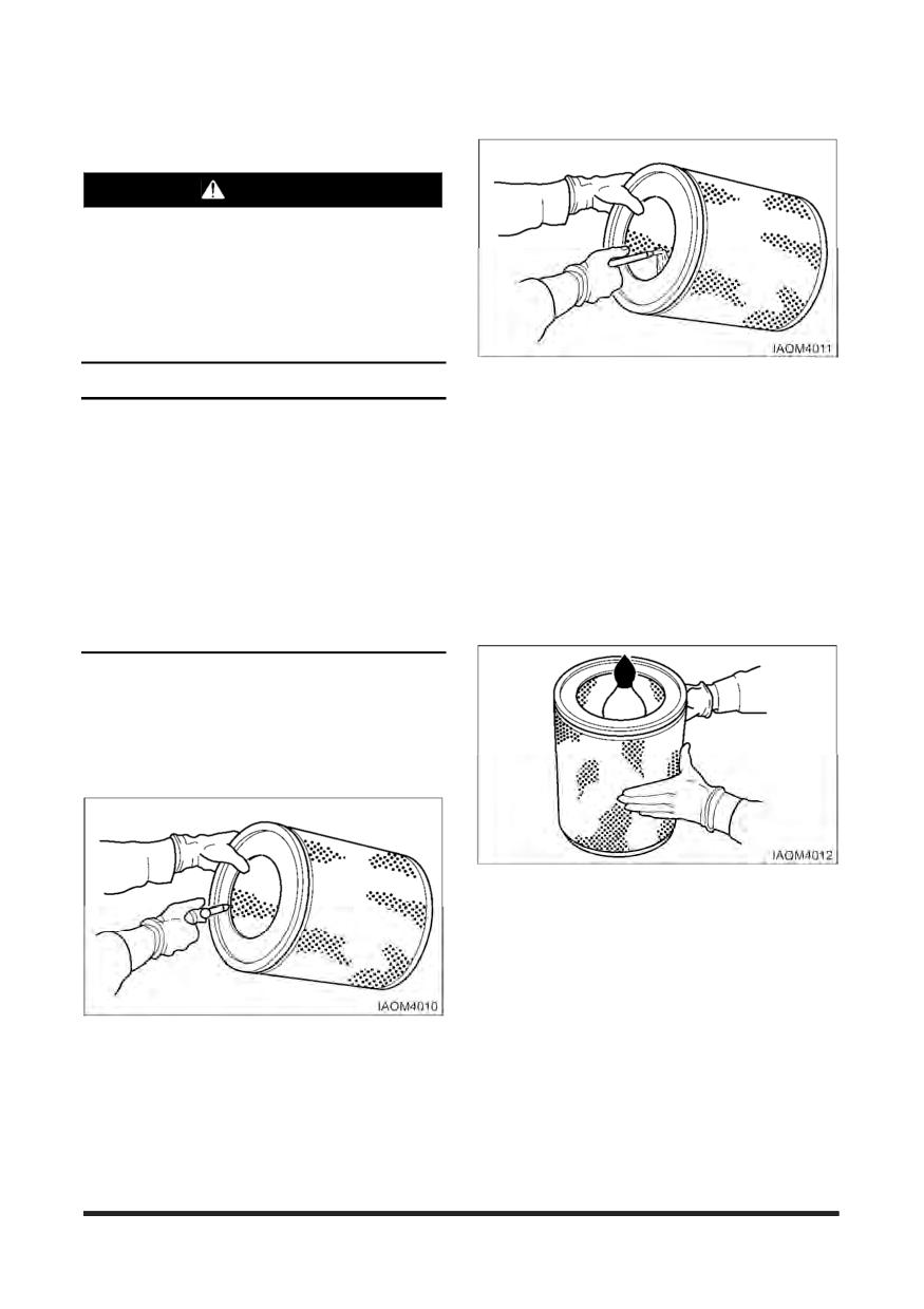
Maintenance Section
Cleaning Primary Filter Elements
Water-280 kPa (40 psi) Maximum
WARNING
Pressure air can cause personal injury.
When using pressure air for cleaning, wear a
protective face shield, protective clothing and
protective shoes.
The maximum air pressure must be below 205
kPa (30 psi) for cleaning purposes.
Direct water on the inside and outside of the
element along the length of the pleats. Air dry it
NOTICE
thoroughly and then examine it.
Do not clean the elements by bumping or tapping
them.
Detergent
Inspect filter elements after cleaning. Do not use a
1. Wash the element in warm water and mild
filter with damaged pleats, gaskets or seals.
household detergent.
When cleaning with pressure air, use 205 kPa (30
2. Rinse the element with clean water. See
psi) maximum pressure to prevent filter element
instructions in preceding topic for cleaning with
damage.
water.
When cleaning with pressure water, use 280 kPa
3. Air dry it thoroughly, and then examine it.
(40 psi) maximum pressure to prevent filter element
damage.
Have spare elements on hand to use while cleaning
used elements.
The primary element should be replaced after a
year’s service or after cleaning no more than 6 times.
1. Insert a light inside the clean dry element and
examine it. Discard the element if tears, rips or
damage are found.
2. Wrap and store good elements in a clean, dry place.
Direct air on the inside and outside of the element
along the length of the pleats. Check the element for
any tears, rips or damage.
-135-
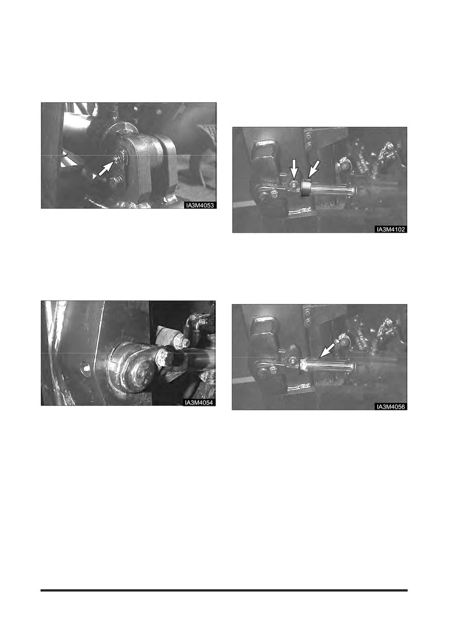
Maintenance Section
Tilt Cylinders - Check, Adjust,
Cylinder Rod Extension
Lubricate
NOTE: The following description is for forward tilt.
For cylinder rod back tilt, the collar should
Chassis Pivot Eyebolts
be stationary by the tilt eye. If it is not, the
O-ring inside the collar may need to be
replaced. To adjust back tilt, spacers must
be added or removed.
Typical Example
1. Lubricate two fittings for the pivot eyebolts, one on
Typical Example
each tilt cylinder.
2. Check the pivot eye pins for loose retainer bolts and
1. Check to make sure the tilt cylinders extend and
wear.
retract evenly.
2. If one cylinder continues to move after the other
cylinder has stopped in full forward or backward tilt,
Mast Pivot Eyes
an adjustment must be made to one cylinder.
Typical Example
Typical Example
3. Lubricate two fittings for the mast pivot eyes, one on
3. To adjust the cylinder rod extension, move the
each side of the mast.
spacer to the rear and loosen the pinch bolt on the
4. Check the pivot eye pins for loose retainer bolts and
clevis.
wear.
4. Turn the cylinder rod in or out of the clevis to obtain
the proper adjustment. Turning the rod into the
clevis shortens the stroke. Turning the rod out of the
clevis lengthens the stroke. When turning for
extending rod, the overlapped length between
clevis’s thread and cylinder rod must be minimum
32 mm
5. Tighten the pinch bolts to a torque of 95 ± 15 N•m
(70 ± 10 lb•ft). Check the cylinder rods again for
even travel.
-136-
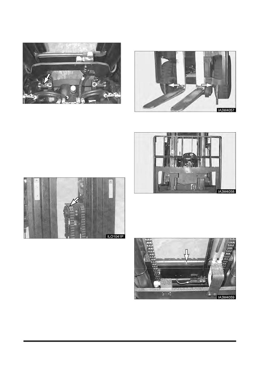
Maintenance Section
Mast Hinge Pins - Lubricate
Carriage Side Rollers Thrust (If
Equipped) - Lubricate
Typical Example
1. Lower the forks and tilt the mast forward.
1. Raise the carriage high enough to gain access to
the side thrust rollers on the back side of the
2. Lubricate the two fittings for the mast hinge pins,
carriage. Block the carriage in this position.
3. one on each side of the mast.
Crosshead Rollers - Inspect
1. Operate the mast through a lift cycle. Watch the
chains move over the crosshead rollers. Make sure
the chain is tracking over the rollers properly.
2. Lubricate 2 side thrust roller fittings, one on each
side of the mast.
3. Raise the carriage, remove the blocking. Lower the
carriage to the floor.
Carriage Sideshifter (If Equipped)
- Lubricate
Typical Example
2. Check for damaged crosshead rollers, guards and
retainer rings.
1. Lubricate 4 (6) fittings. The forks may have to be
moved to gain access to all of the fittings.
2. Operate the sideshifter carriage through several
complete cycles to distribute the grease the carriage
to the floor.
-137-
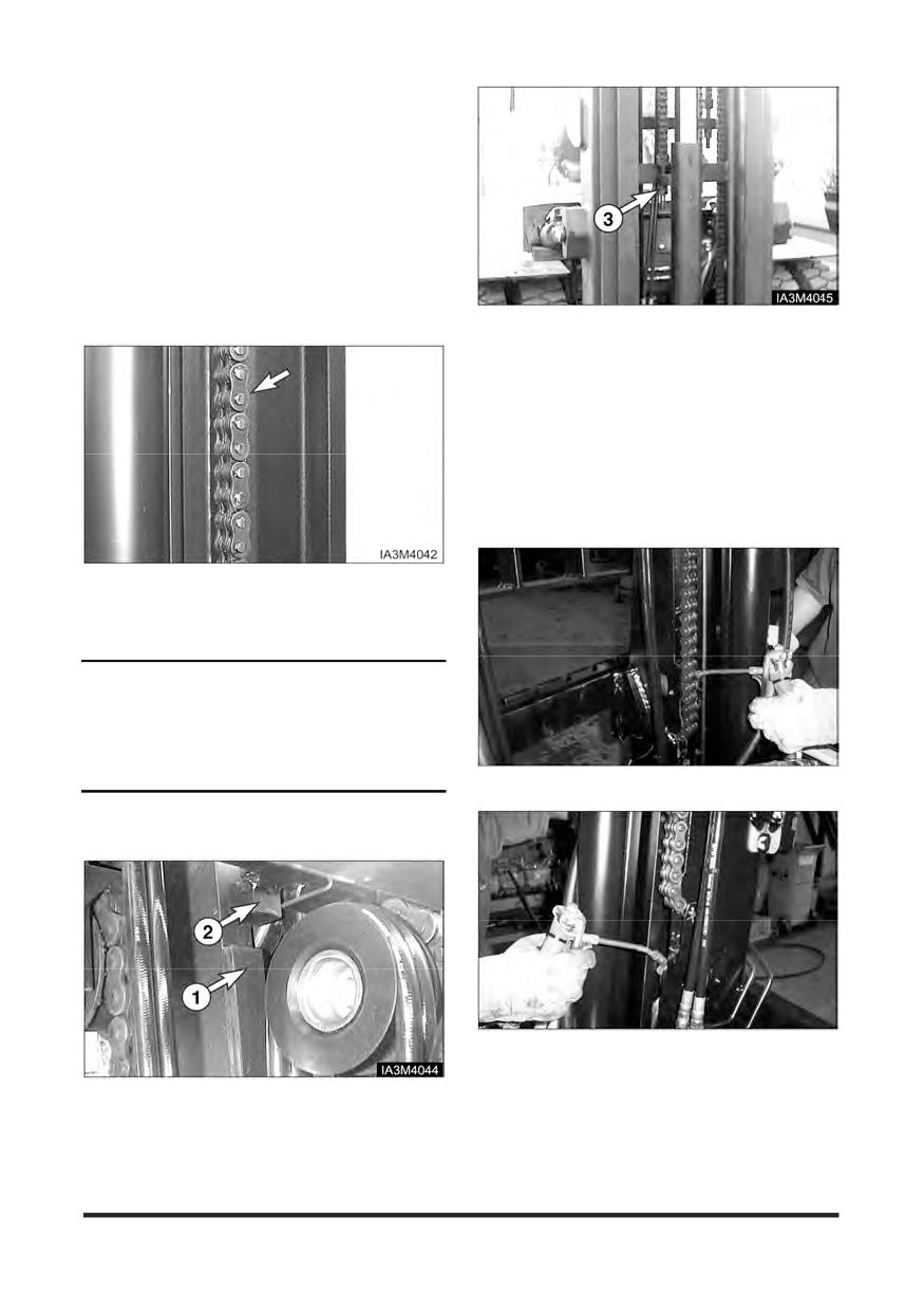
Maintenance Section
Mast, Carriage, Lift Chains, &
Attachments - Check, Lubricate
1. Operate the lift, tilt and attachment controls. Listen
for unusual noises. These may indicate a need for
repair.
2. Inspect for loose bolts and nuts on the carriage.
Remove any debris from the carriage and mast.
3. Inspect the forks and attachments for free operation
and damage. Have repairs made if necessary.
7. In case of Full Free Lift Mast, Extend the primary
cylinder to full length and then check the clearance
and over lapped dimension between carriage
stopper bolt or block (1) and Inner mast stopper
block (2). Adjust the chain anchor bolt (3) so that
clearance should be 14 ± 2 mm.
8. And adjust the overlapped dimension to be 10 ± 2
mm by moving or inserting washer.
Carriage Side Rollers - Lubricate
4. Brush a film of oil on all links of the chain.
5. Raise and lower the carriage a few times to work
lubricant into the chain links.
NOTICE
Lubricate chains more frequently than normal in
applications where the lift truck is operating in a
atmosphere which could cause corrosion of
components or when lift truck must work in rapid lift
cycles.
GC35S-5, GC40S-5, GC45S-5
6. Inspect the chain anchors and individual links for
wear, loose pins or cracked leaves.
GC50C-5, GC55C-5
Lubricate 2 side roller fittings, one on each side of
the carriage
-138-
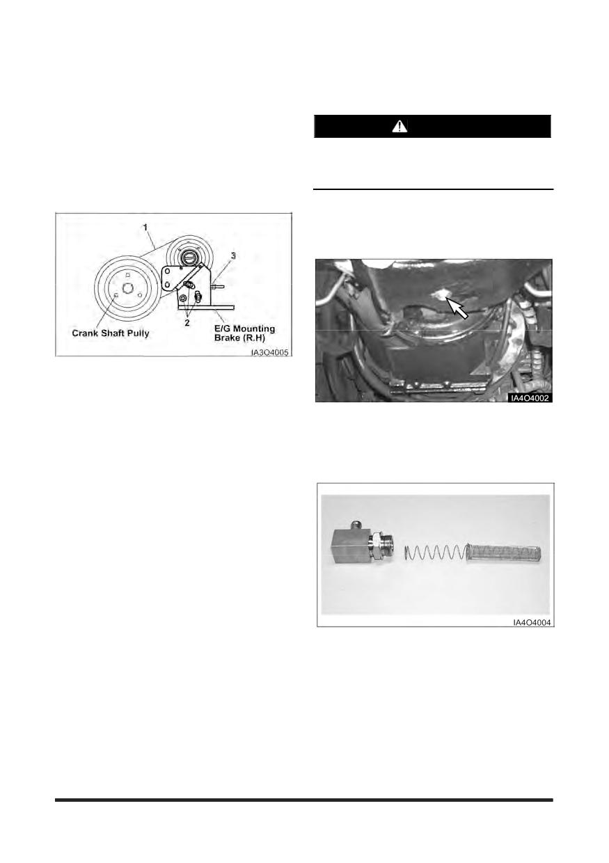
Maintenance Section
Drive Axle Oil & Strainer (OCDB
Parking Brake - Test, Adjust
Only) - Check, Clean, Change
See topic, “Parking Brake - Test, Adjust” in “First 50-
100 Service Hours.”
WARNING
Hot oil and components can cause personal
Circulation Pump Belt (OCDB & LP
injury. Do not allow hot oil or components to
contact skin.
Engine Only. If Eguipped) - Check,
Adjust
Park the lift truck on a level surface. Apply the
parking brake. Place the directional control level in
NEUTRAL and stop the engine.
1. Check the condition and adjustment of the belt (1).
Correct adjustment allows
10 mm
(3/8 inch)
deflection under 45 N of force.
2. To adjust the circulation pump belt, loosen the
1. Remove drain plug. Allow the oil to drain into a
mounting bolts (2) and adjust the adjusting inner nut
suitable container. Clean the magnetic drain plug.
(3). Tighten the adjusting outer nut (4).
Check O-ring seal and replace if necessary.
3. Lower the hood and seat assembly.
2. Install the drain plug.
3. Remove strainer assembly.
4. Washer the strainer assembly in clean,
nonflammable solvent and dry it.
5. Install the strainer assembly and reconnect the hose
and harness.
-139-
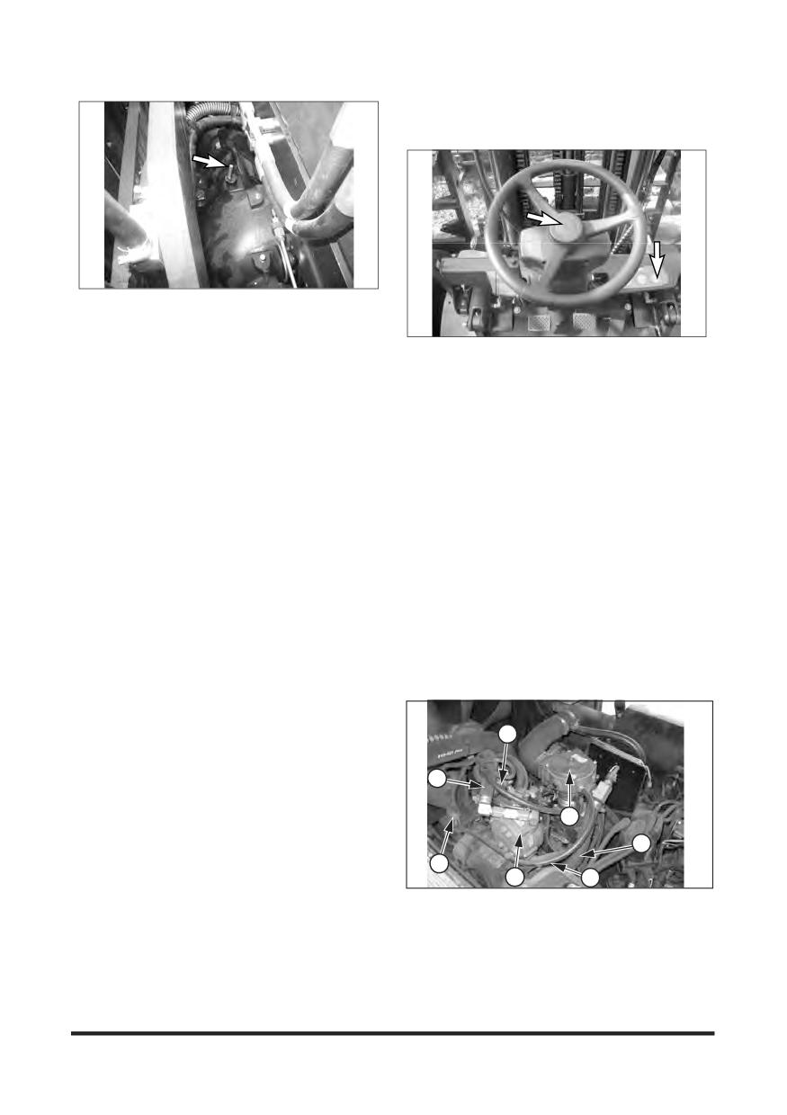
Maintenance Section
Horn & Lights (If Equipped) -
Check
6. Remove the dip stick/filter cap. Fill the drive axle
housing with oil. See “Lubricant Specification - Drive
Axle Oil” and “Refill Capacity”.
1. Press horn button, to determine if horn is
7. Start the lift truck. With the engine at low idle, place
operational.
the directional control lever to the NEUTRAL.
2. Check and replace all defective gauges.
8. Maintain the oil level between lower mark and upper
3. Check all lights such as warning, directional, backup,
mark on the dip stick/filter cap.
driving and flood lights for correct operation.
9. Install the dip stick/filter cap.
Replace all burned out bulbs. Have repairs made if
needed.
Inspect Vacuum Lines and Fittings
(LP Engine only)
1. Visually inspect vacuum lines and fittings for
physical damage such as brittleness, cracks and
kinks. Repair/replace as required.
2. Solvent or oil damage may cause vacuum lines to
become soft resulting in a collapsed line while the
engine is running.
3. If abnormally soft lines are detected, replace as
necessary.
1
6
4
7
3
2
5
(1) LP fuel lock-off, (2) LP regulator/converter,
(3) Fuel Trim Valve,
(4) LP mixer, (5) Vacuum lines,
(6) Coolant lines, (7) LP fuel line
-140-
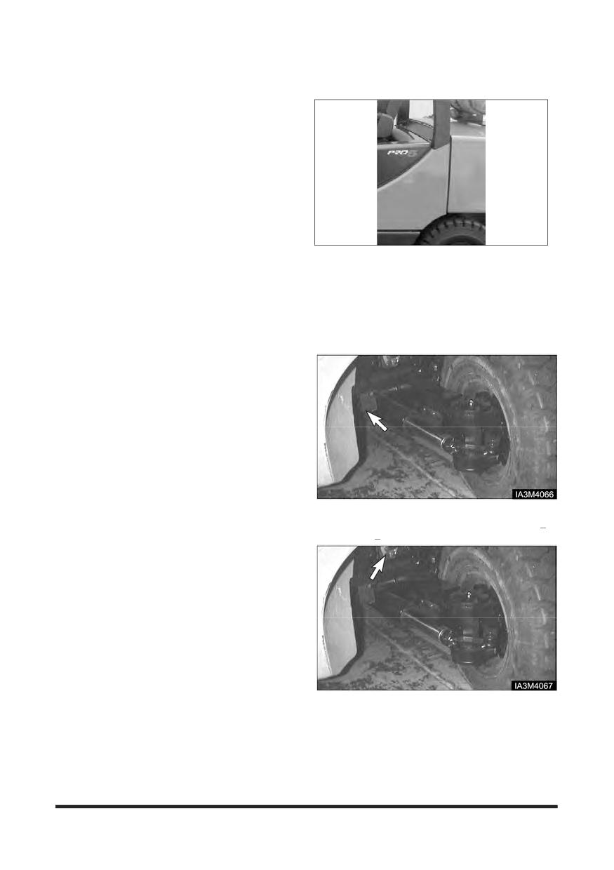
Maintenance Section
Overhead Guard - Inspect
Fuel Trim Valve(FTV) Inspection
(PSI Engine only)
1. Visually inspect the Fuel trim valve(3) for abrasions
or cracking. Replace as necessary.
2. To ensure the valve is not leaking a blow-by test
can be performed.
3. With the engine off, disconnect the electrical
connector to the FTV.
4. Disconnect the vacuum line from the FTV to the
pressure regulator/converter, at the converter’s tee
connection.
5. Lightly blow through the vacuum line connected to
1. Check tightness of overhead guard mounting bolts
the FTV. Air should not pass through the FTV when
at 95 N·m (70 lb·ft).
de-energized. If air leaks past the FTV when de-
energized, replace the FTV.
2. Check overhead guard for bent or cracked sections.
Have repairs made if needed.
Inspect Electrical System (LP
Steer Suspension - Inspect
Engine only)
1. Check for loose, dirty or damaged connectors and
wires on the harness including: Fuel lock-off, TMAP
sensor, O2 sensor, Electronic throttle, Control
Relays, Fuel Trim Valve, Foot Pedal, and Distributor
sensor.
2. Repair and/or replace as necessary.
1. Inspect the suspension mounting bolts. Tighten
suspension mounting bolts, if necessary, to 240+30
N·m (180+20 lb·ft).
2. Look for leaks at the power steering hose
connections.
3. Remove any trash buildup on the suspension or the
steer axle.
-141-
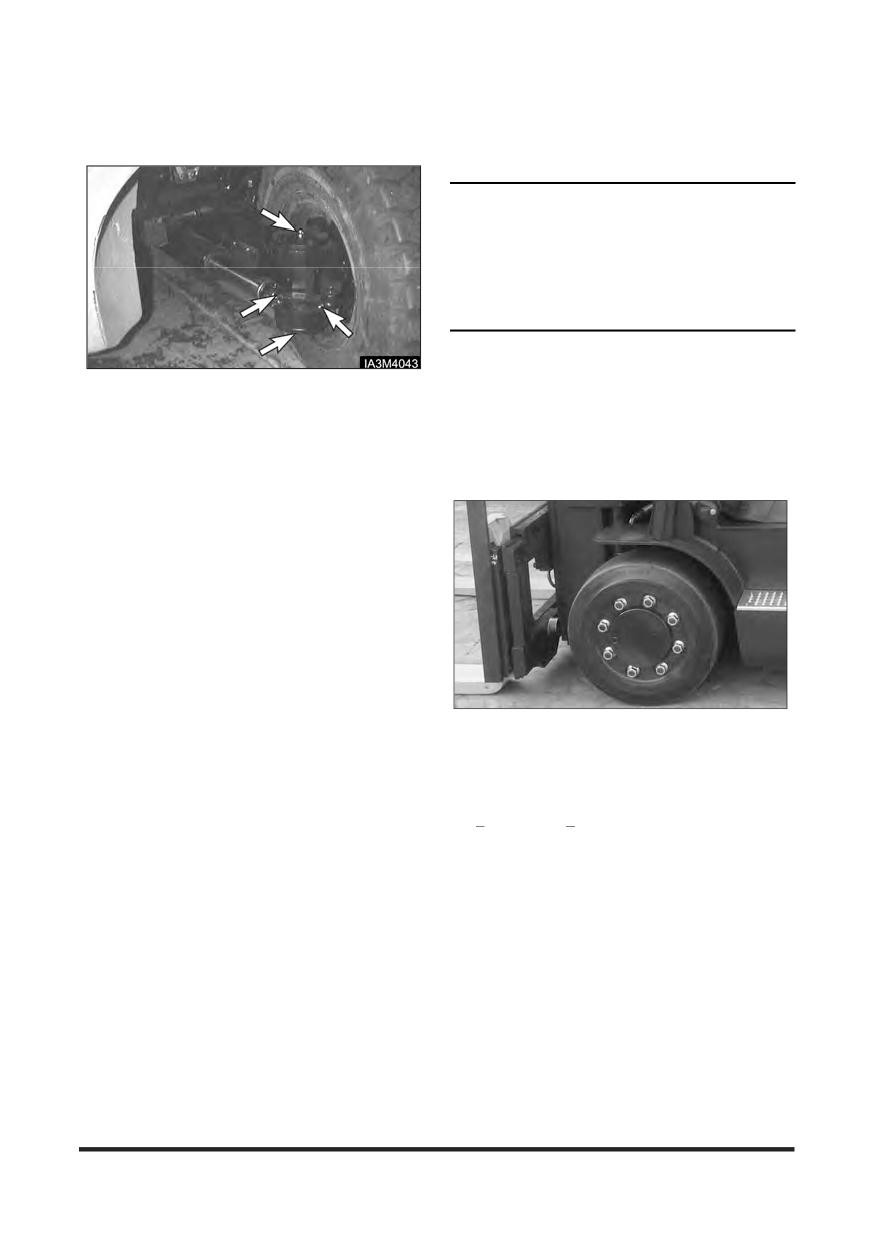
Maintenance Section
Steering Mechanism - Check,
Wheel Bolts and Nuts - Inspect
Lubricate
Inspect Tightness
NOTICE
Do not lubricate ball seas of wheels or ball faces of
wheel nuts.
Be sure mounting faces of hub, wheel nuts and flat
mounting surfaces are clean.
Tighten wheel nuts again after 24 hours of operation.
NOTE: Always tighten wheel lug nuts in a
sequence opposite (180°) each other.
1. Lubricate the steer axle king pins, total of four fittings.
If equipped with dual wheels, follow the same nut
Two on the right side and two on the left side.
tightening sequence for both wheels.
2. Lubricate the steering link bearings, total of four
fittings. Two on the right side and two on the left
side.
Drive Wheels
3. Check for any worn or loose components of the
steering mechanism. Remove any debris or trash
as required.
Install drive wheel. Put two nuts opposite (180°)
each other. Tighten both.
Install the remaining nuts. Tighten all nuts in a
sequence opposite (180°) each other. Tighten to
600+90 N•m (440+60 lb•ft).
-142-
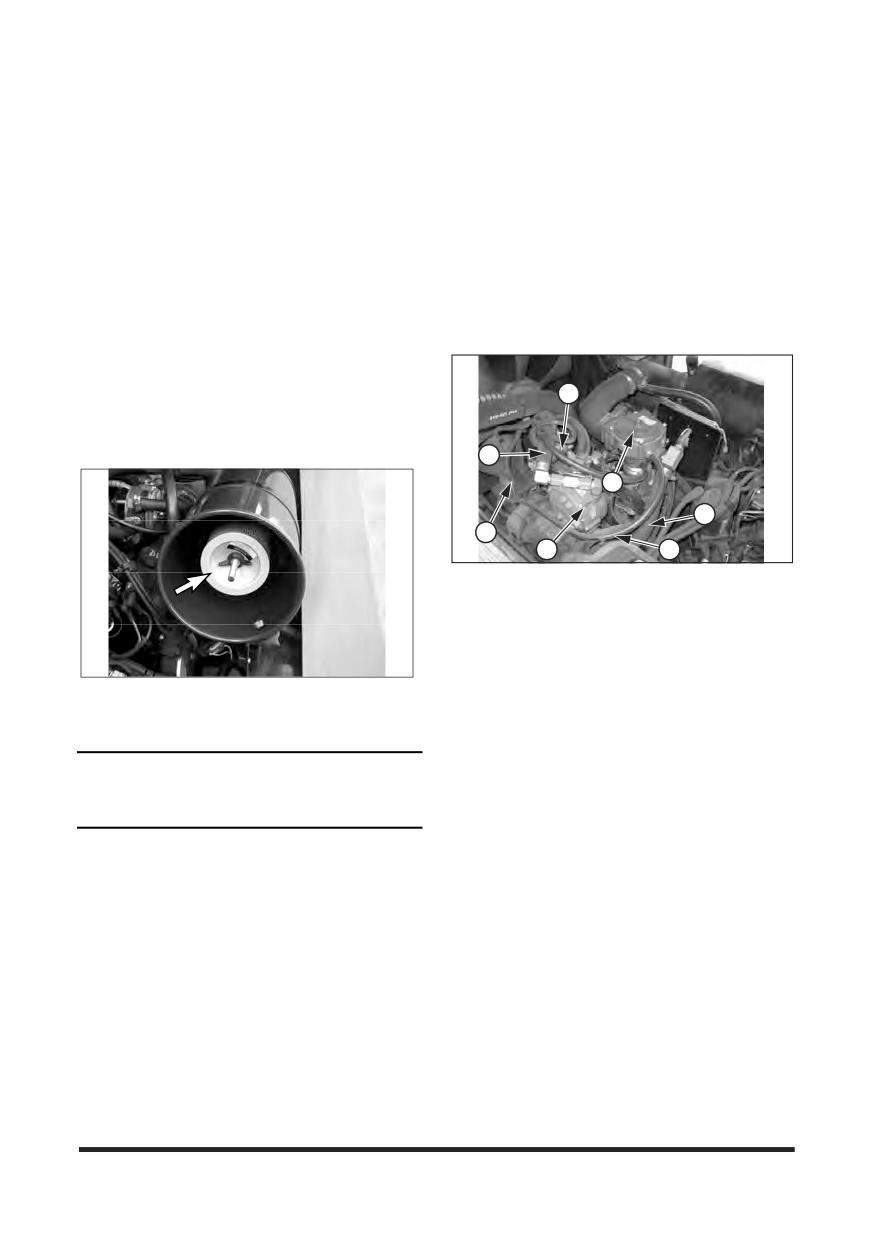
Maintenance Section
Every 1000 Service Hours or 6 Months
You must read and understand the warnings and instructions contained in the Safety section of this manual,
before performing any operation or maintenance procedures.
Air Intake System - Change
Inspect Coolant Hoses (LP
Engines Only)
Changing Primary Element
See topic, “Air Intake System - Check, Clean” in
1. Visually inspect coolant hoses and clamps.
“Every
500 Service Hours or Monthly”.
Remember to check the two coolant lines that
connect to the pressure regulator/converter.
2. Replace any hose that shows signs of swelling,
cracking, abrasion or deterioration.
Changing Secondary Element
Replace the secondary element after the primary
element has been cleaned three times or yearly.
1
1. Remove the primary air cleaner element. See topic
“Servicing Filter Element”. Clean the inside of the air
cleaner housing and cover.
6
4
7
3
2
5
(1) LP fuel lock-off, (2) LP regulator/converter
(3) Fuel Trim Valve(FTV), (4) LP mixer
(5) Vacuum lines, (6) Coolant lines, (7) LP fuel line
LP Regulator/Converter Inspection
2. Remove the secondary element. Inspect the gasket
between the air cleaner housing and the engine
(LP Engine Only)
inlet. Replace the gasket if it is damaged.
1. Visually inspect the pressure regulator/converter
housing(2) for coolant leaks and detect the fuel pipe
NOTICE
joints, LP mixer and regulator/converter for LP fuel
leaks.
Always replace the secondary element. Do not
attempt to reuse it by cleaning.
To detect the LP fuel leaks, smear detected parts
with suds, visually inspect whether there are
bubbles after the engine start.
3. Install a new secondary element. Install a new or
cleaned primary element. Install the cover. Tighten
NOTE: For pressure testing and internal inspection
the latches.
of the pressure regulator/converter, contact
to the CROWN service.
4. Start the engine and observe the air cleaner service
indicator. If the indicator shows RED after installing
a new secondary element and a cleaned primary
(outer) element, replace the cleaned primary filter
with a new element.
5. Stop the engine. Close the hood and seat assembly.
-143-
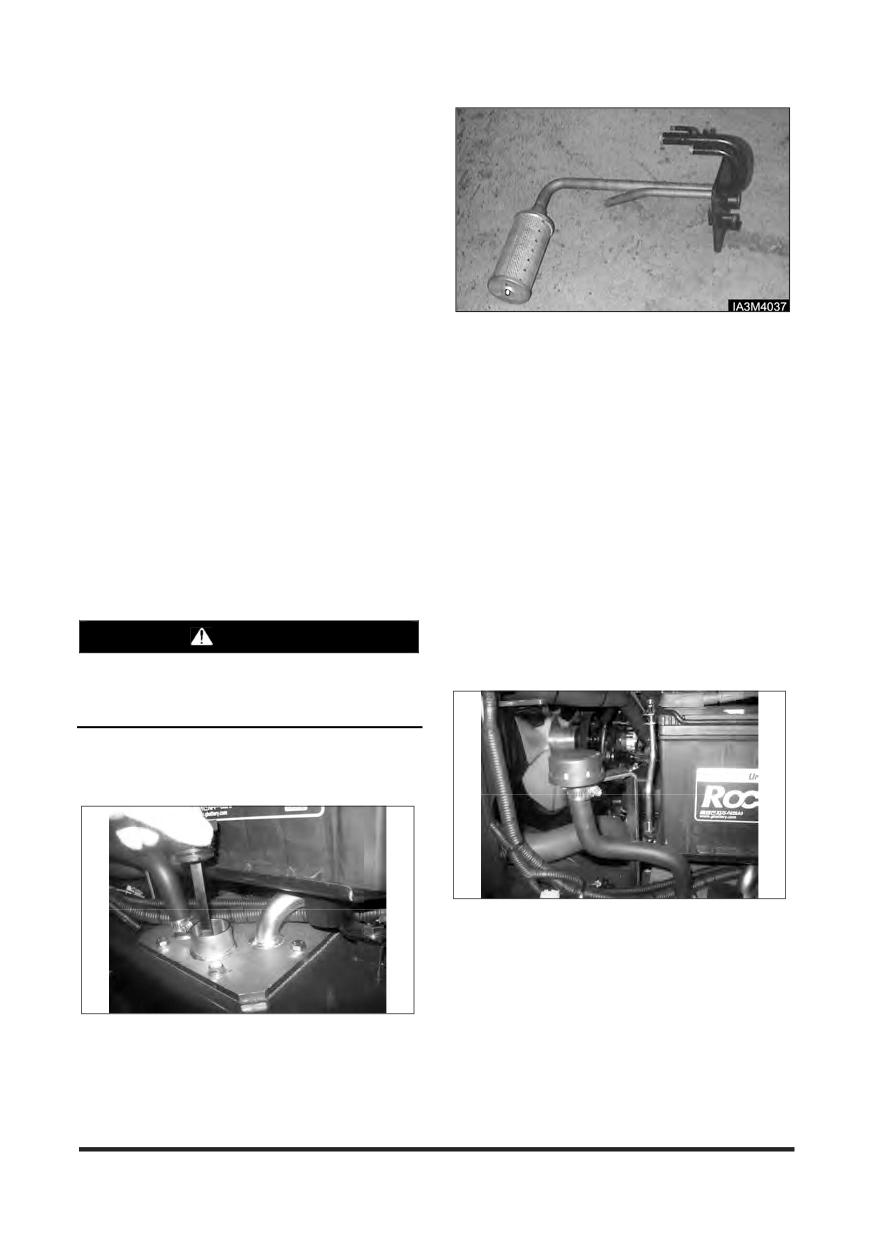
Maintenance Section
Fuel Lines & Fittings - Check
Visually inspect fuel lines and fittings for physical
damage. Replace as required.
Inspect Mixer Assembly (LP
Engine Only)
Refer to the LP mixer section of the engine service
manual for procedures.
2. Remove filter assembly from the hydraulic tank
cover.
Inspect Throttle Assembly (LP
3. Install new filter assembly in the hydraulic tank
Engine Only)
cover.
1. Visually inspect the throttle assembly motor housing
4. Inspect cover gasket for damage, replace it if
for coking, cracks and missing cover-retaining clips.
necessary.
Repair and/or replace as necessary.
5. Clean and Install the cover and tighten retaining
NOTE: Refer to the LP mixer and throttle section of
bolts.
the service manual for procedures on
6. Lower the hood and seat assembly.
removing the mixer and inspecting the
throttle plate.
Air Breather - Change
Park the lift trucks level, with the forks lowered,
Hydraulic Return Filter - Change
parking brake engaged, transmission in NEUTRAL
and the engine stopped.
WARNING
1. Raise the hood and seat assembly.
Hot oil and components can cause personal
2. Remove and discard the air breather.
injury. Do not allow hot oil or components to
contact skin.
Park the lift truck level with the forks lowered,
parking brake engaged, transmission in NEUTRAL
and the engine stopped.
3. Install a new air breather.
4. Lower the hood and seat assembly.
Transmission Oil, Oil Filter &
1. Raise the hood and seat assembly. Loosen the
Strainer - Clean, Change
bolts of the hydraulic tank cover, and remove the
See topic, “Transmission Oil, Oil Filter & Strainer -
hydraulic tank cover with filter assembly.
Clean, Change” in “First 50 - 100 Service Hours or a
Week”.
-144-
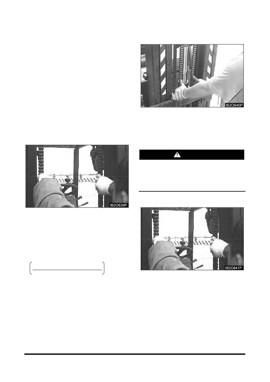
Maintenance Section
Lift Chains - Test, Check, Adjust
Check for Equal Tension
Lift Chain Wear Test
Inspect the part of the chain that is normally
operated over the cross head roller. When the chain
bends over the roller, the movement of the parts
against each other causes wears.
Inspect to be sure that chain link pins do not extend
outside of the link hole. If any single link pin is
extended beyond its connecting corresponding link,
it should be suspected of being broken inside of its
link hole. Lift chains are required to check for wear
about every 1,000 service hours or 6 months.
Chain wear test is a measurement of wear of the
Typical example
chain links and pins. Take the following steps to
check chain wear.
Lift the carriage and the mast high enough for
getting tension on lift chains. Check the chains, and
1. Lift the mast and carriage enough for getting tension
make sure the tension is the same. Lift chains are
on lift chains.
required to check for equal tension about every
1,000 service hours or 6 months.
WARNING
Personal injury can be caused by sudden
movement of the mast and carriage.
Keep hands and feet clear of any parts that can
move.
Lift Chain Adjustment
Typical example
2. Measure precisely ten links of chain distance at the
centre of pins in millimeter.
3. Calculate chain wear rate*.
4. If the chain wear rate is 2% or more, replace the lift
chain.
*Chain wear rate (%)
=
Actual measurement - Pitch** X 10
X 100
Typical example for carriage equal tension
Pitch** X 10
If the tension is not the same on both chains, take
the procedure as follows.
**Chain Pitch for GC35/40/45S-5, GC50/55C-5
NOTE: If carriage height is not correct, make
= 25.40 mm(1.0 in)
adjustments by following procedures.
-145-
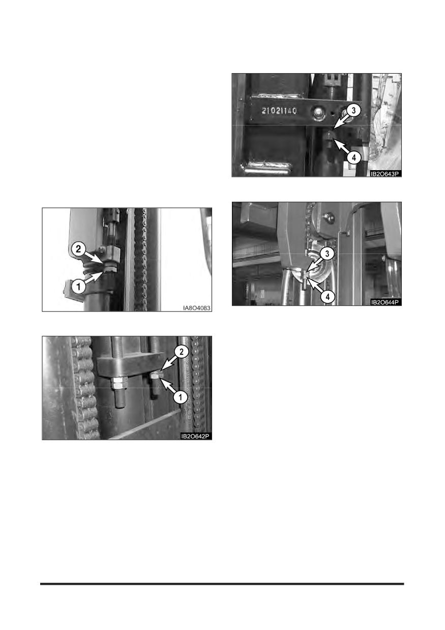
Maintenance Section
Carriage Chain Adjustment
Mast Chain Adjustment - FF, FFT Mast
Make sure that carriage height is correct. If correct,
adjust the chain for equal tension. If not, adjust the
chain for correct carriage height by adjusting anchor
nuts(1),(2).
NOTE: See the previous section, “Carriage Roller
Extrusion” in “When Required” for proper
height of carriage.
1. Fully lower the carriage and tilt mast forward or lift
the carriage and put blocks under the carriage to
release the tension from the lift chains.
2. Loosen nut(1) and adjust nut(2) to get proper
distance from bottom of inner upright to the bottom
Typical example for FF mast
of carriage bearing.
Typical example for FFT mast
Typical example for carriage chain of STD mast
Make sure that mast height is correct. If correct,
adjust chain for equal tension. If not, adjust mast
chain for correct mast height by adjusting anchor
nuts (3), (4).
NOTE: See the previous section, “Carriage Roller
Extrusion” in “When Required” for proper
inner mast height.
1. Lift the inner mast and put blocks under the inner
mast to release the tension from the lift chains.
2. Loosen nut(3) and adjust nut(4) to make inner mast
rail flush with outer mast rail bottom.
Typical example for carriage chain of FF,FFT mast
3. Make adjustment anchor nuts(3),(4) for equal chain
tension.
3. Make adjustment anchor nut(1),(2) for equal chain
tension.
4. Raise the inner mast and check equal chain tension.
If not equal, repeat the same procedure as step 1
4. Set the mast vertical and raise the carriage and
through step 3.
check equal chain tension. If not equal, repeat the
same procedure as step 1 through step 3.
5. Put LOCTITE No. 242 tread lock on the threads of
the anchor nuts(3),(4) after the adjustment is
5. Put LOCTITE No. 242 Tread lock on the threads of
completed.
the anchor nuts(1),(2) after the adjustment is
completed.
-146-
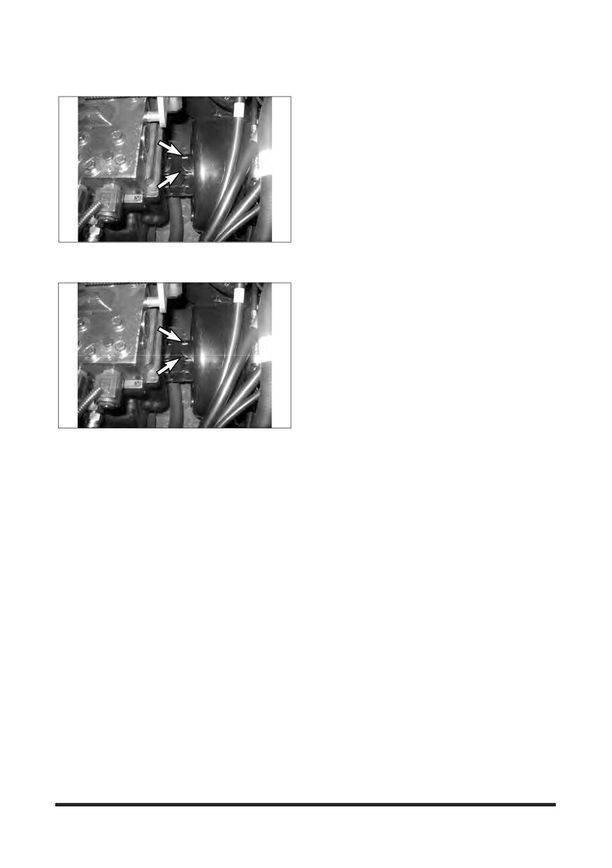
Maintenance Section
Universal Joint - Inspect
1. Inspect for loose retaining bolts. Check for worn or
damaged bearings.
2. Have worn or damaged bearings replaced. Tighten
the bolts if necessary.
-147-
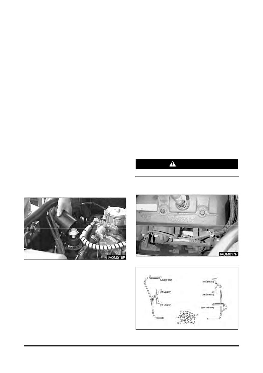
Maintenance Section
Every 1500 Service Hours or 9 Months
You must read and understand the warnings and instructions contained in the Safety section of this manual,
before performing any operation or maintenance procedures.
Drive Axle Oil (Shoe Brake Only) -
Replace Spark Plugs (LP Engine
Check, Clean, Change
Only)
See topic, “Drive Axle Oil - Check, Clean, Change”
1. Disconnect Battery Cables.
in “First 50-100 Service Hours or a Week”.
2. Using a gentle twisting motion remove the high
voltage cables from the spark plugs. Replace any
damaged cables.
Inspect Ignition System (LP
3. Remove the spark plugs.
Engine Only)
4. Gap the new spark plugs to the proper
specifications.
1. Disconnect Battery Cables.
PSI Engine : 0.9 mm (0.035 inch)
2. Remove and inspect the spark plugs. Replace as
required.
5. Apply anti-seize compound to the spark plug
3. Test secondary cables with an Ohmmeter. If
threads and install.
maximum resistance is higher than 25 kOhms,
repair and/or replace.
PSI Engine : 30 N·m (22 lb·ft)
4. Remove distributor cap and perform visual
inspection. Replace cap and rotor if corrosion is
WARNING
found on the contacts.
Do not overtighten the spark plugs.
5. Inspect the ignition coil for cracks and heat
deterioration. Visually inspect the coil heat sink fins.
If any fins are broken replace as required.
6. Re-install the high voltage cables.
-148-
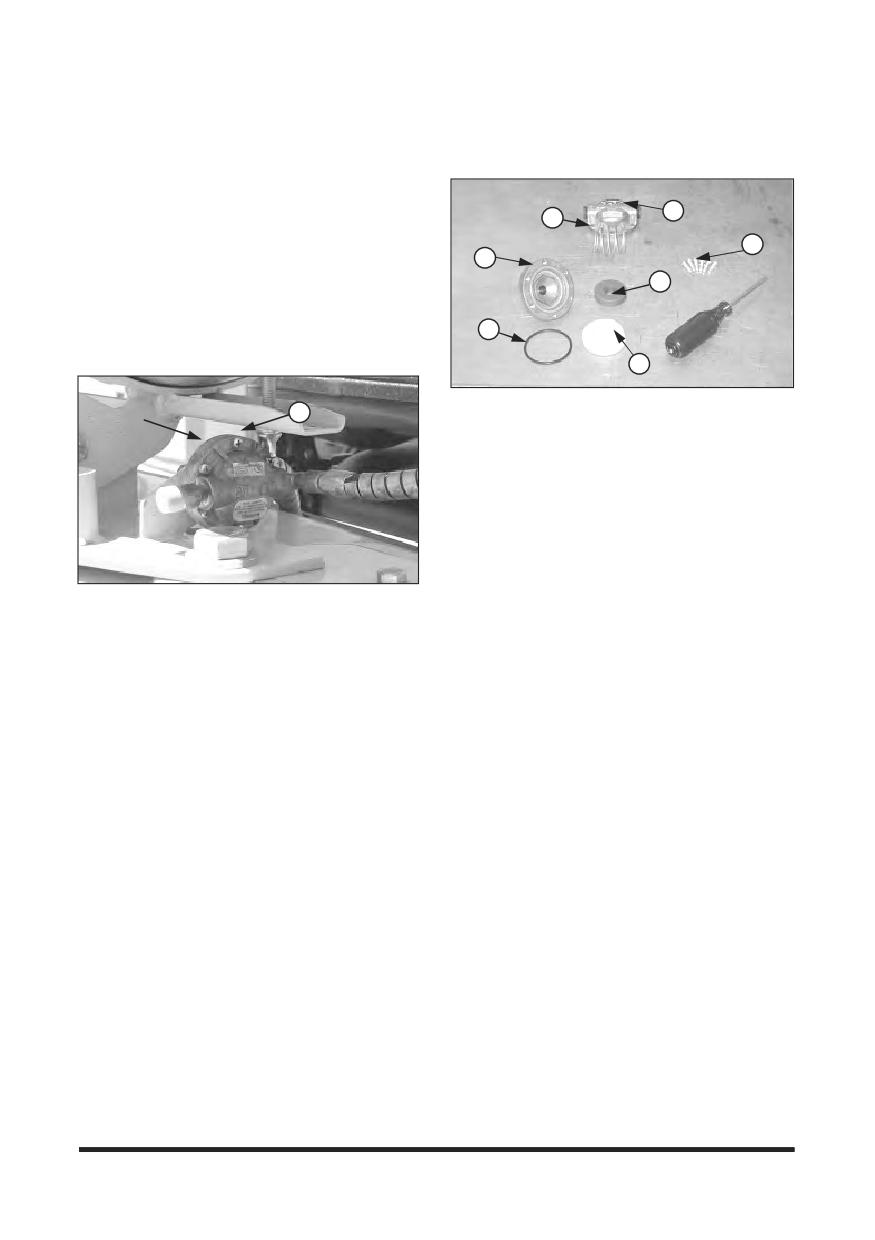
Maintenance Section
Replace LP Fuel Filter Element (LP
Fuel Filter (LP Engine Only)
Engine Only)
Disassembly
Park the lift truck in an authorised refueling area with
the forks lowered, parking brake applied and the
transmission in Neutral.
2
4
1. Close the fuel shutoff valve on the LP-Fuel tank.
1
Run the engine until the fuel in the system runs out
5
and the engine stops.
3
2. Turn off the ignition switch.
3. Scribe a line across the filter housing covers, which
will be used for alignment purposes when re-
6
installing the filter cover.
7
1. Remove top cover (2), magnet (3), spring (4), and
Filter
1
filter element (7) from bottom cover (5).
Housing
2. Replace the filter element (7).
Scribe
Point
3. Check bottom cover O-ring seal (6) for damage.
Replace if necessary.
4. Re-assemble the filter assembly aligning the scribe
lines on the top and bottom covers.
5. Install the cover retaining screws, tightening the
screws in an opposite sequence across the cover.
6. Open the fuel valve by slowly turning the valve
4. Remove the cover retaining screws (1)
counterclockwise.
7. Crank the engine several revolutions to open the
fuel lock-off. DO NOT START THE ENGINE. Turn
the ignition key switch to the off position.
8. Check the filter housing, fuel lines and fittings for
leaks. Repair as necessary.
-149-
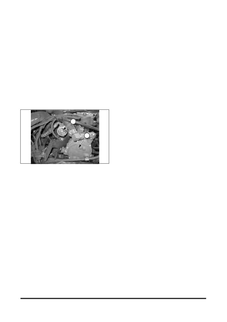
Maintenance Section
Testing Fuel Lock-off Operation
(LP Engine Only)
1. Start engine.
2. Locate the electrical connector for the fuel lock
3. Disconnect the electrical connector.
4. The engine should run out of fuel and stop within a
short period of time.
5. Turn the ignition key switch off and re-connect the
fuel lock-off connector.
NOTE: The length of time the engine runs on
trapped fuel vapor increases with any
increase in distance between the fuel lock-
off and the pressure regulator/converter.
1
2
(1) LP fuel lock-off, (2) LP regulator/converter
-150-
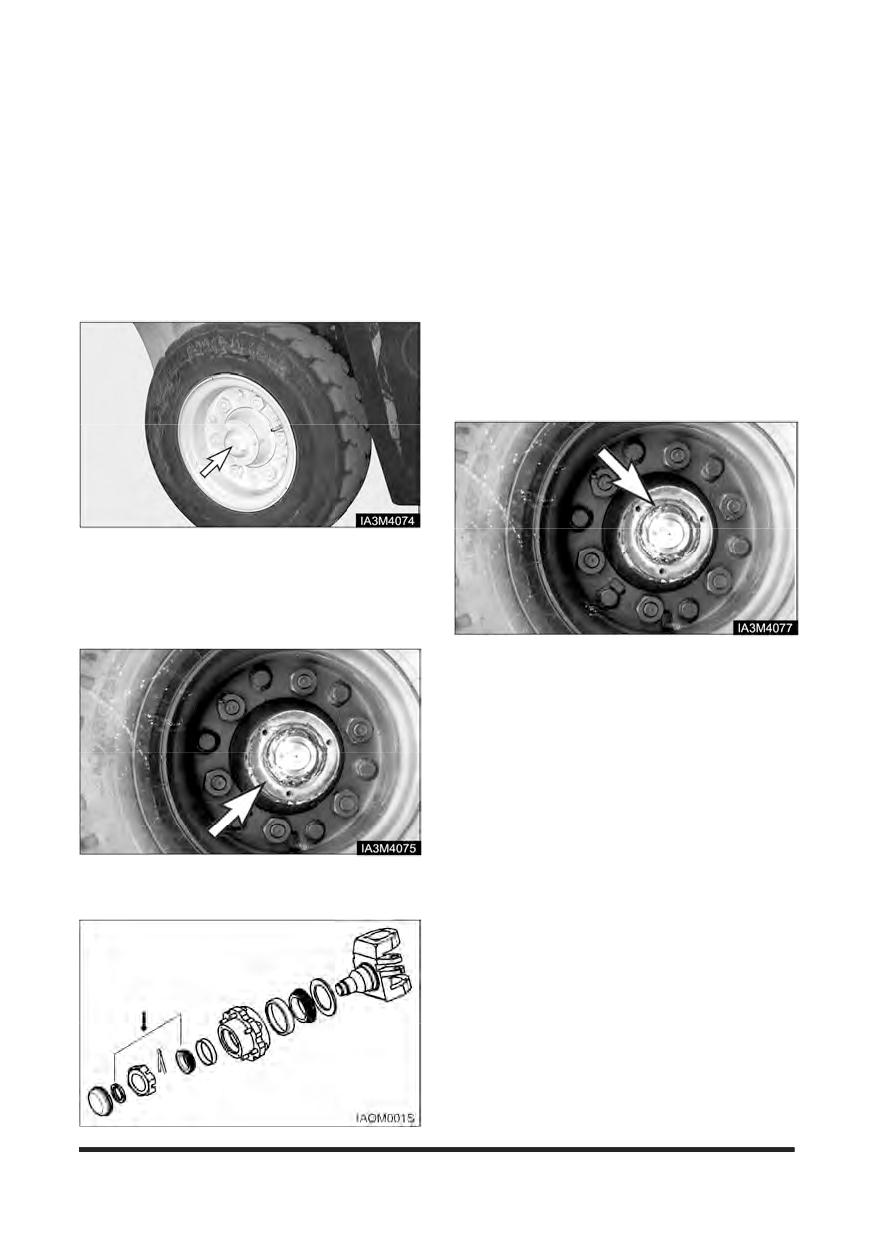
Maintenance Section
Every 2000 Service Hours or Yearly
You must read and understand the warnings and instructions contained in the Safety section of this manual,
before performing any operation or maintenance procedures.
4. Remove the castle nut and washer.
Steer Wheel Bearings -
5. Remove the wheel assembly. Examine the seal for
Reassemble
damage and wear. Replace the seal if necessary.
Park the lift truck level with the forks lowered,
6. Remove the inner bearing. Clean and lubricate the
parking brake engaged, transmission in NEUTRAL
and the engine stopped.
steering knuckle. Reassemble both the inner and
outer bearing cones.
7. Install the inner bearing. Lubricate the seal and
install the wheel assembly on the knuckle.
8. Install the outer wheel bearing and the outer washer.
Install a new lock washer and fit the locknut.
Typical Example
1. Lift the steer wheels off the ground. Place stands or
blocking under the frame and steer axle to support
the lift truck.
2. Remove the hub cap.
Typical Example
9. Tighten the locknut to 135 N•m (100 lb•ft), while
turning wheel hub to seat the bearing.
10. Loosen the locknut. Retorque it to 50 ± 5 N•m (37 ±
4 lb•ft). Bend the lockwasher tang to secure locknut.
11. Install the hub cap.
12. Raise the lift truck and remove the blocking Lower
the lift truck to the ground.
Typical Example
3. Remove the cotter pin.
-151-
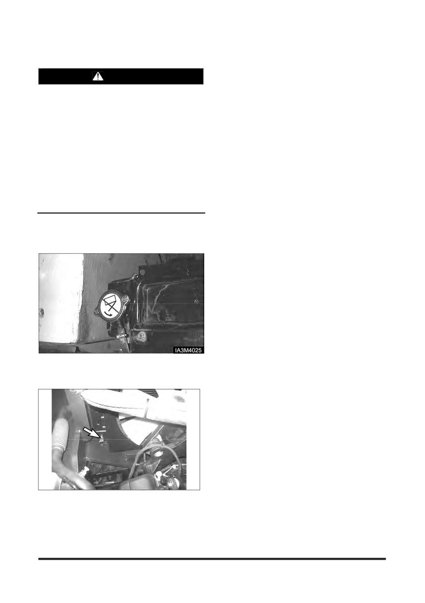
Maintenance Section
4. Close radiator drain valve and install block drain
Cooling System - Clean, Change
plug. Fill the cooling system with 1 kg (2 lb) sodium
bisulphate per 40 liters (10 gallons) of water. Most
WARNING
commercial cooling system cleaners can be used.
5. Start and run the engine for 30 minutes.
At operating temperature, the engine coolant is
hot and under pressure.
6. Stop the engine and drain the cleaning solution.
Steam can cause personal injury.
7. Flush the system with clean water, until draining
water is clear.
Check the coolant level only after the engine has
been stopped and the filter cap is cool enough
8. Close the drain valve and install the block drain plug.
to touch with your bare hand.
Fill the system with neutralizing solution, 250g (1/2
lb) sodium carbonate per 40 liters (10 gallons) of
Remove the filter cap slowly to relieve pressure.
water.
Cooling system conditioner contains alkali.
9. Start and run the engine for 10 minutes.
Avoid contact with the skin and eyes to prevent
10. Stop the engine and drain the neutralizing solution.
personal injury.
11. Flush the system with clean water until draining
Use all cleaning solutions with care.
water is clear.
12. Close the drain valve and install the block drain plug.
The lift truck must be level, the forks lowered, the
Add coolant to the top of the filter neck.
parking brake engaged, the transmission in
13. Start and run the engine to stabilise the coolant level.
NEUTRAL and the engine stopped and cool.
See “Every 10 Service hours or Daily”, “Coolant
Level-Check”, in this manual.
1. Turn the radiator cap slowly to relieve the pressure,
then remove the cap.
2. Remove the block drain plug.
Typical Example
3. Open radiator drain valve. Allow the coolant to drain.
Drain the recovery bottle.
-152-
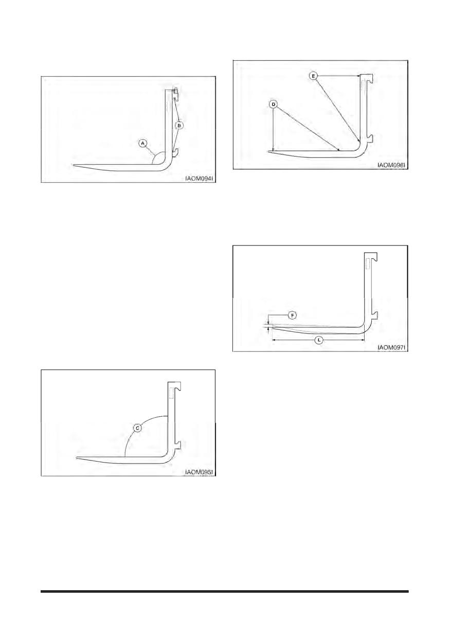
Maintenance Section
Fork - Inspect
3.
Check the straightness of the upper face of blade
(D) and the front face of shank (E) with a straight
Forks should be inspected, at a minimum, every 12
edge.
months. If the truck is being used in a multi-shift or
heavy duty operation, they should be checked every
The fork should be withdrawn from service if the
six months.
deviation from straightness exceeds 0.5 percent
of the length of the blade and/or the height of the
1. Inspect the forks carefully for cracks. Special
shank respectively 5 mm/1000 mm (0.18"/36").
attention should be given to the heel section (A), all
weld areas and mounting brackets (B). Inspect the
top and bottom hooks on forks used on hook type
carriages and tubes on shaft mounted forks.
Forks with cracks should be removed from
service. "Wet Test" magnetic particle inspection
is generally preferred due to its sensitivity and
the ease of interpreting the results. Portable
equipment is usually recommended so it can be
moved to the lift truck.
Inspectors should be trained and qualified in
accordance with The American Society for Non
Destructive Testing, Level II Qualifications.
4.
Check the difference in height of one fork tip to the
other when mounted on the fork carrier. A difference
in fork tip height can result in uneven support of the
load and cause problems with entering loads.
The maximum recommended difference in fork
tip elevation (F) is 6.5 mm (0.25") for pallet forks
and 3 mm (0.125") for fully tapered forks. The
maximum allowable difference in fork tip
elevation between the two or more forks is 3
percent of blade length (L).
Replace one or both forks when the difference in
fork tip height exceeds the maximum allowable
difference. Contact your local CROWN Lift Truck
2. Check the angle between the upper face of the
Dealer for further information.
blade and the front face of the shank. The fork
should be withdrawn from service if angle (C)
exceeds 93 degrees or deviates by more than 3
degrees from an original angle other than
90
degrees, as may be found in some special
application forks.
-153-
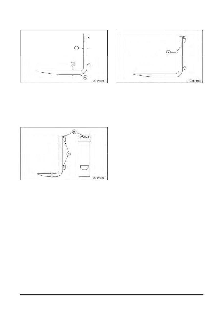
Maintenance Section
8. Check fork markings (N) for legibility. Renew
5.
Check the fork blade (J) and shank (H) for wear with
markings as required to retain legibility.
special attention to the heel (G). The fork should be
withdrawn from service if the thickness is reduced to
9. a. Lift the mast and operate the tilt control lever, until
90 percent or less of the original thickness.
the top surface of the forks is parallel with the floor.
Place two straight bars that are the same width as
Fork blade length may also be reduced by wear,
the carriage, across the forks as shown.
especially on tapered forks and platens. Remove
the forks from service when the blade length is
b. Measure the distance from the bottom of
no longer adequate for the intended loads.
each end of the two bars to the floor. The
forks must be parallel within 3 mm (.12 in) for
Full Tapered and Polished (FTP) forks, all
other forks 6.4 mm (.25 in), for their complete
length.
c. Put one fork, one third from the tip, under a
fixture that will not move. Then operate the tilt
control with caution until the rear of the truck
lifts just off the floor. Follow the same
procedure with the second fork. Repeat Step
a.
6.
Check the fork mountings (K) for wear, crushing and
other local deformation, which can cause excessive
side to side wobble of the forks. Excessive
clearance on hook type forks may allow them to fall
from the carrier. Forks which show visible signs of
such damage should be removed from service.
7.
Check the positioning lock and other fork retention
devices to make sure they are in place and working.
Hook type forks use a spring loaded pin (M),
located in the top hook, to engage notches in the
top carriage bar to hold the fork in place.
When adjusting the fork spacing, the forks are
prevented from sliding off the end of the carriage by
stop blocks. These stop blocks are at both ends of
the carriage and in the path of the bottom fork hook.
The load backrest extension may be used in place
of the stop blocks in some cases.
Shaft mounted forks may use set collars or spacers
on the shaft to either side of the fork. They may also
use U bolts, pins, or similar devices which engage
the fork through the top structure of the carriage.
-154-
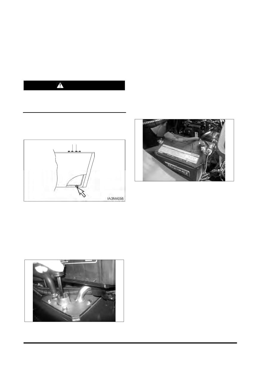
Maintenance Section
Every 2500 Service Hours or 15 Months
You must read and understand the warnings and instructions contained in the Safety section of this manual,
before performing any operation or maintenance procedures.
FULL mark on the dipstick.
Hydraulic Oil - Check, Clean,
Change
Inspect Battery System
1. Clean battery outer surfaces with a mixture of
WARNING
baking soda and water.
Hot oil and components can cause personal
2. Inspect battery outer surfaces for damage and
injury. Do not allow hot oil or components to
replace as necessary.
contact skin.
3. Remove battery cable and clean, repair and/or
replace as necessary.
Park the lift truck level with the forks lowered, mast
tilted back (all cylinders retracted), parking brake
engaged, transmission in NEUTRAL and the engine
stopped.
1. Remove the hydraulic tank drain plug. Allow the oil
to drain. Clean and install the plug.
2. Raise the hood and seat assembly.
3. Remove dipstick/filter cap. Fill the hydraulic tank.
See “Refill Capacities.” Install the breather/dipstick.
4. Lower the hood and seat assembly.
5. Start the engine and operate the hydraulic controls,
and the steering system, through a few cycles to fill
the lines. Look for oil leaks.
6. Stop the engine and check the oil level. With all
cylinders retracted, maintain the oil level to the
-155-
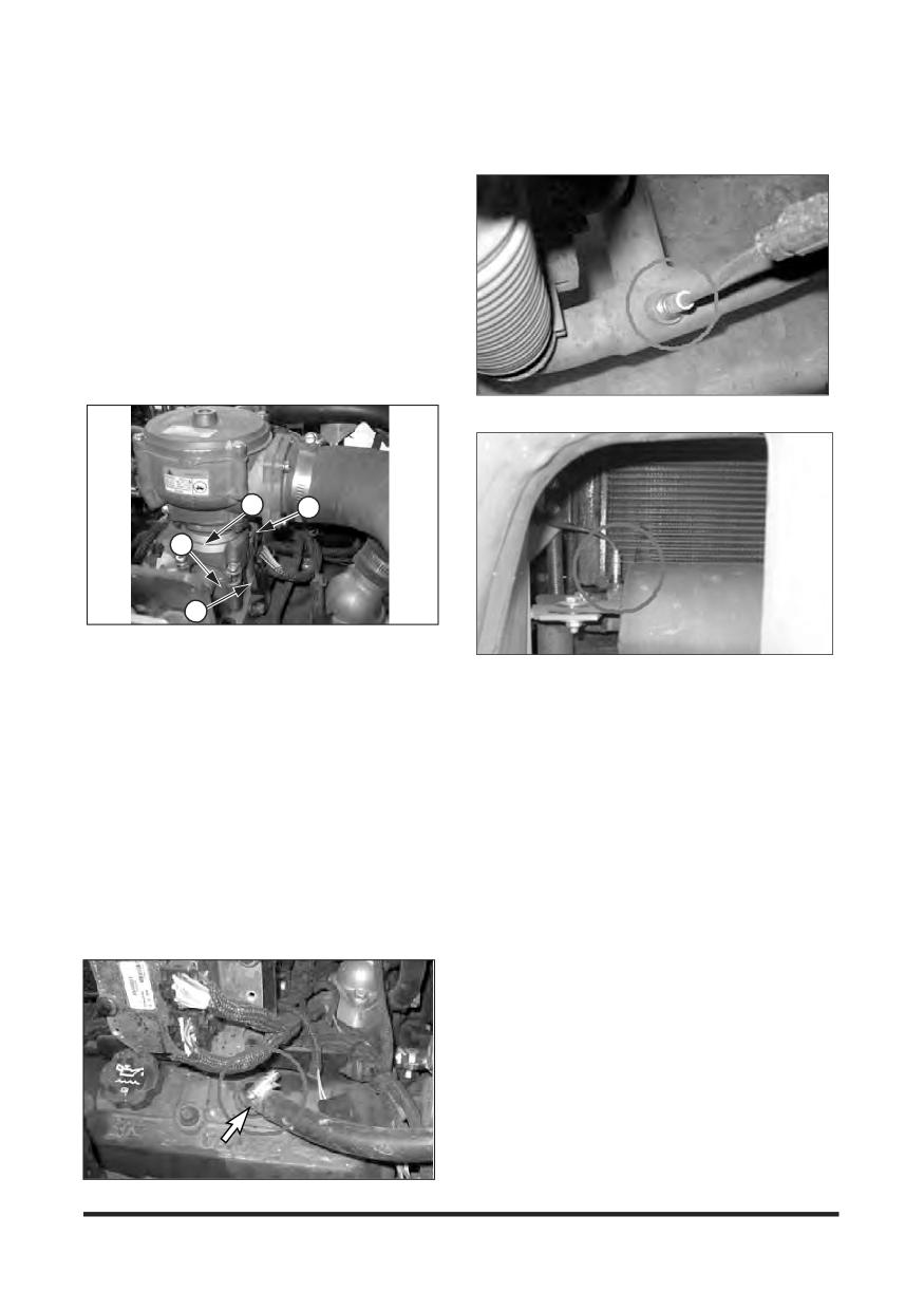
Maintenance Section
Checking the TMAP Sensor (LP
Replace Oxygen Sensor (PSI
Engine Only)
Engine)
1. Verify that the TMAP sensor (2) is mounted tightly
into the manifold adapter (3), with no leakage.
2. If the TMAP is found to be loose, remove the TMAP
retaining screw and the TMAP sensor from the
manifold adapter.
3. Visually inspect the TMAP O-ring seal for damage.
Replace as necessary.
4. Apply a thin coat of an approved silicon lubricant to
the TMAP o-ring seal.
5. Re-install the TMAP sensor into the manifold
adapter and securely tighten the retaining screw.
Exhaust Tube
1
4
3
2
(1) Adapter-Throttle body, (2) TMAP sensor,
(3) Adapter-Manifold, (4) Throttle body
Muffler Ass’y
Inspect for Intake Leaks (LP
When indicated by MIL, replace oxygen sensors on
Engine Only)
the exhaust tube and muffler assembly.
1. Visually inspect the intake manifold, throttle
assembly
(4), and manifold adapters
(3), for
1. Stop engine and wait until the exhaust pipe and
looseness and leaks. Repair as necessary.
exhaust pipe is cooled.
Replace PCV Valve and breather
2. Disconnect the electrical connector of oxygen
sensor.
element - Change (LP Engine
3. Remove oxygen sensor.
Only)
4. Assemble new oxygen sensor Tightening torque :
2. Loosen the hose clamps and remove the PCV valve.
45 N·m (32.5 lb·ft)
3. Assemble new PCV valve and hose.
5. Connect the electrical connector of oxygen sensor.
4. Tighten the hose clamps
-156-
Environment Protection Section
Environment Protection
When servicing this lift truck, use an authorised
servicing area and an approved container to collect
coolant, oil, fuel, grease, electrolyte and any other
potential environmental pollutant before any lines,
fittings or related items are disconnected or removed.
After servicing, dispose of those materials in an
authorised place and container. When cleaning the
lift truck, be sure to use an authorised area.
-157-
Index Section
Chassis Pivot Eyebolts
136
Index
Check Coolant Level
122
Check for Equal Tension
145
Checking Element
135
#
Checking Service Indicator
123
Checking the TMAP Sensor (LP Engine Only)
156
12 Months Inspection
105
Circuit Breaker
44,120
Circulation Pump Belt (OCDB & LP Engine Only. If
Eguipped) - Check, Adjust
139
A
Cleaning Primary Filter Elements
135
Coolant Information
108
Accelerator Pedal
47
Coolant Level - Check, Clean
122
Adjustments
87
Coolant Water
109
Air-205 kPa (30 psi) Maximum Pressure
135
Coolant
15
Air Breather - Change
144
Cooling System - Clean, Change
152
Air Cleaner Indicator - Check
123
Cooling System Specifications
108
Air Intake System - Change
143
Crosshead Rollers - Inspect
137
Air Intake System - Check, Clean
134
Crushing or Cutting Prevention
14
Antifreeze
109
Cylinder Rod Extension
136
Attachment Abbreviations (Includes Special Forks)
...................................................................................40
Auto Shift Controller ASC - 206 (Standard)
87
D
Avoiding Lift Truck Tipovers
21
Daily Inspection
104
Declaration of Conformity
30
B
Detergent
135
Direction Control Lever
46
Batteries
15
Disassembly
149
Battery Terminal - Clean, Inspect
121
Drive Axle Oil - Check, Clean, Change
130
Before Operating the Lift Truck
12
Drive Axle Oil & Strainer (OCDB Only) - Check,
Before Starting the Engine
51
Clean, Change
139
Before Starting the Lift Truck
11
Drive Axle Oil (Shoe Brake Only) - Check, Clean,
Before Storage
96
Change
148
Bent or Twisted Forks
103
Drive Axle Oil Level - Check
126
Brake Fluid
112
Drive Axle Oil
112
Brake Oil Level - Check
126
Drive Wheels
142
Brake Pedal Adjustment Warning
8
Bulbs
120
Burn Prevention
15
E
Electrical Disconnect Switch (If Equipped)
44
C
Electronic Controlled Spark-Ignition Engines
55
Engine Compartment
43
Capacity Chart (Not used in Australia)
34,36
Engine Oil & Filter - Change
133
Capacity Chart (with Side Shifter) (Not used in
Engine Oil (DEO and EO)
111
Australia)
35,37
Engine Oil Level - Check
122
Carriage Chain Adjustment
146
Environment Management
3
Carriage Roller Extrusion - Check, Adjust
121
Environment Protection
102,157
Carriage Side Rollers - Lubricate
138
Every 10 Service Hours or Daily
122
Carriage Side Rollers Thrust (If Equipped) -
Every 1000 Service Hours or 6 Months
143
Lubricate
137
Every 1500 Service Hours or 9 Months
148
Carriage Sideshifter (If Equipped) - Lubricate
137
Every 2000 Service Hours or Yearly
151
Causes of Fork Failure
103
Every 250 Service Hours or Monthly
133
Centre of Gravity (CG)
21
Every 2500 Service Hours or 15 Months
155
Changing LP Tanks
49
Every 500 Service Hours or 3 Months
134
Changing Primary Element
143
Changing Secondary Element
143
-158-
Index Section
F
Inspect Electrical System (LP Engine only)
141
Inspect Engine for Exhaust Leaks
123
Falling Objects Protective Structure(FOPS)
14
Inspect Engine for Fluid Leaks
122
Fatigue
103
Inspect for Intake Leaks (LP Engine Only)
156
Fire or Explosion Prevention
15
Inspect Ignition System (LP Engine Only)
148
First 50 - 100 Service Hours or a Week
128
Inspect Mixer Assembly (LP Engine Only)
144
First Installation
104
Inspect Throttle Assembly (LP Engine Only)
144
Fluid Penetration
14
Inspect Tightness
142
Foreword
2
Inspect Vacuum Lines and Fittings (LP Engine only)
Fork - Inspect
153
................................................................................. 140
Fork Inspection
104
Inspection, Maintenance and Repair of Lift Truck
Fuel Filter (LP Engine Only)
149
Forks
102
Fuel Lines & Fittings - Check
144
Instrument Panel
41
Fuel Specifications
110
Fuel Trim Valve(FTV) Inspection (PSI Engine only)
.................................................................................141
J
Fuse & Relay (LP Engine Only)
120
Fuses
119
Jacking Information
100
Fuses, Bulbs & Circuit Breaker - Change, Reset
Jacking Procedure
101
.................................................................................119
L
G
Lift Chain Adjustment
145
General Fuel Information
110
Lift Chain Wear Test
145
General Hazard Information
10
Lift Chains - Test, Check, Adjust
145
Lift Control
47
Lift Fork Adjustment
95
H
Lift Truck Capacity Rating
39
Lift Truck Controls
46
Hook - on type Fork
95
Lift Truck Operation
84
Horn & Lights (If Equipped) - Check
140
Lift Truck Parking
13
How to Fix Forklift to a Carrier
98
Lift Truck Shipping
97
How to Survive in a Tipover (If Operator Restraint
Lift Truck Stability Base
22
System Equipped)
29
Lift Truck Stability
21
Hydraulic Jack & Jack Stand Capacity
100
Lifting a Forklift using a Crane
98
Hydraulic Oil - Check, Clean, Change
155
Lifting Drums or Round Objects
93
Hydraulic Oil (HYDO)
111
Lifting the Load
90
Hydraulic Oil Level - Check
126
Literature Information
2
Hydraulic Return Filter - Change
144
Load Backrest Must Be In Place Warning
7
Loading or Unloading Trucks/Trailers
13
Long Time Storage
96
I
LP Engine Crankcase
133
LP Engine
53
LP Regulator/Converter Inspection (LP Engine Only)
Identification, Lift Capacity and Attachment Plate
................................................................................. 143
...................................................................................39
LP Specifications
110
If Optional Suspension Seat (weight adjusting type)
Lubricant Information
111
Equipped
18
Lubricant Specifications
111
Important Safety Information
4
Lubricant Viscosities and Refill Capacities
113
Improper Modification or Repair
103
Lubricant Viscosities
113
Inching into Loads
90
Lubricating Grease (MPGM)
112
Inching
85
Index
158
Inspect Acceleration Pedal Operation(PSI Engine)
.................................................................................123
M
Inspect Battery System
155
Inspect Coolant Hoses (LP Engines Only)
143
Machine Lifting and Tiedown Information
97
-159-
Index Section
Maintenance and Repair
105
Pressure Air
14
Maintenance Information
14
Pressure Warning
7
Maintenance Intervals
114
Prestart Conditions
53
Maintenance
3
Product Description
87
Make proper antifreeze additions
109
Mast Abbreviations
40
Mast Chain Adjustment - FF, FFT Mast
146
R
Mast Channels - Lubricate
125
Mast Hinge Pins - Lubricate
137
Refill Capacities
113
Mast Pivot Eyes
136
Refueling
49
Mast, Carriage, Lift Chains, & Attachments - Check,
Replace LP Fuel Filter Element (LP Engine Only)
Lubricate
138
................................................................................. 149
Metric Hardware
106
Replace Oxygen Sensor (PSI Engine)
156
Metric ISO2 Thread
107
Replace PCV Valve and breather element - Change
Mono-Ped Control System (Option)
86
(LP Engine Only)
156
Mounting and Dismounting
11
Replace Spark Plugs (LP Engine Only)
148
Moving Fan Warning
9
S
N
Safety Rules
23
No Riders Warning
9
Safety
2,5
No Standing On Forks Warning, No Standing Under
Seat Adjustment
17
Forks Warning
7
Seat Belt
19
Noise and Vibration
33
Seat Switch System (If Equipped)
45
Noise
33
Seat
44
Seat, Hood Latch & Support Cylinder - Check,
Lubricate
118
O
Serial Number Locations
38
Serial Number
38
Oil Cooled Disc Brake (OCDB) Type
127,130
Service Brake Pedal
47
Oil Cooled Disc Brake (OCDB)
112
Servicing Filter Element
134
Oil Cooled Disc Brake Only
112
Sideshift Attachment Control (If Equipped)
48
Oils
15
Specifications
31
Operating in hot weather
93
Stability and Centre of Gravity
21
Operating Techniques
90
Starting From a 12 Volt External Source
54
Operating the Lift Truck
12
Starting the Engine
53
Operation Information
11
Starting the Lift Truck
12
Operation
2,88
Steer Suspension - Inspect
141
Operator's Warning and Identification Plate
39
Steer Wheel Bearings -Reassemble
151
Operator Restraint System (If Equipped)
17
Steering Knob (If Equipped)
86
Operator’s Station and Monitoring Systems
41
Steering Mechanism - Check, Lubricate
142
Operator’s Warning Plate
39
Storage Information
96
Overhead Guard - Inspect
141
Overhead Guard Must Be In Place Warning
8
Overloading
103
T
Table of Contents
1
P
Test Fuel System for Leaks (LP Engine Only)
118
Testing Fuel Lock-off Operation (LP Engine Only)
Parking Brake - Test, Adjust
131,139
................................................................................. 150
Parking Brake Adjusting
131
Tilt Control
48
Parking Brake Lever
47
Tilt Cylinders - Check, Adjust, Lubricate
136
Parking Brake Testing
131
Tilt Steering Column
44
Parking brake
9
To Adjust
132
Parking the Lift Truck
94
To Operate the Lift Truck After a Long Time Storage
Power Shift Transaxle
84
................................................................................... 96
-160-
Index Section
Torque for Metric Fasteners
107
Torque for Standard Bolts, Nuts, and Taperlock
Studs
106
Torque for Standard Hose Clamps - Worm Drive106
Torque Specifications
106
Torques for Bolts and Nuts With Standard Threads
.................................................................................106
Torques for Taperlock Studs
107
Towing Information
99
Training Required to Operate or Service Warning... 5
Transmission Inching Control Pedal
46
Transmission Oil (TDTO)
112
Transmission Oil Level - Check
125
Transmission Oil, Oil Filter & Strainer - Clean,
Change
128,144
Transmission Speed Range Lever
46
Transportation Hints
97
Traveling With the Load
91
Turning
92
U
Universal Joint - Inspect
147
Unloading
91
V
Vibration(weighted overall value)
33
W
Walk - Around Inspection
51
Walk - Around Inspection - Inspect
124
Warning Signs and Labels
5,17
Water-280 kPa (40 psi) Maximum Pressure
135
Wheel Bolts and Nuts - Inspect
142
When Required
118
-161-