Diesel engine 12 V 4000 G21R, 12 V 4000 G41R. Operating Instructions (2011)
Table of Contents
1 Safety
4.5 Operational checks
41
4.6 Stop engine in manual mode (testing
1.1 General conditions
7
mode)
42
1.2 Personnel and organizational requirements
8
4.7 Emergency stop
43
1.3 Transport
9
4.8 After stopping the engine - Engine remains
1.4 Crankshaft transport locking device
10
ready for operation
44
1.5 Safety regulations for startup and operation
13
4.9 After stopping the engine - putting the
1.6 Explosion hazard when removing
engine out of service
45
inspection port cover on engine
14
4.10 Plant - Cleaning
46
1.7 Safety regulations for maintenance and
repair work
15
1.8 Fluids and lubricants, fire prevention and
environmental protection
18
5 Maintenance
1.9 Conventions for safety instructions in the
5.1 Maintenance task reference table [QL1]
47
text
20
6 Troubleshooting
2 General Information
6.1 Troubleshooting
48
2.1 Engine side and cylinder designations
21
6.2 Fault messages on engine governor
51
2.2 Engine layout
22
7 Task Description
3 Technical Data
7.1 Engine
63
3.1 12V 4000 engine data, continuous
7.1.1
Engine - Barring manually
63
operation, variable 3B, optimized fuel
7.1.2
Engine - Barring with starting system
64
consumption
23
7.1.3
Engine - Test run
65
3.2 12V 4000 engine data, continuous
operation, variable 3B, emissions optimized
7.2 Cylinder Liner
66
w/o certificate
27
7.2.1
Cylinder liner - Endoscopic examination
66
7.2.2
Cylinder liner - Instructions and comments on
3.3 12V 4000 engine data, continuous
endoscopic and visual examination
68
operation, variable 3B, emissions optimized
(TA-Luft)
31
7.3 Crankcase Breather
70
3.4 Final compression pressure
34
7.3.1
Crankcase breather - Oil separator
3.5 Firing order
35
replacement, diaphragm check and
3.6 Engine - Main dimensions
36
replacement
70
7.4 Valve Drive
72
7.4.1
Valve gear - Lubrication
72
4 Operation
7.4.2
Valve clearance - Check and adjustment
73
7.4.3
Cylinder head cover - Removal and
4.1 Putting the engine into operation after
installation
75
extended out-of-service periods (>3
7.5 Injection Pump / HP Pump
76
months)
37
7.5.1
HP pump - Relief bore check
76
4.2 Putting the engine into operation after
scheduled out-of-service-period
38
7.6 Injection Valve / Injector
77
4.3 Start engine in manual mode (testing
7.6.1
Injector - Replacement
77
mode)
39
7.6.2
Injector - Removal and installation
78
4.4 Starting the engine in emergency situations
7.7 Fuel System
83
(override mode)
40
7.7.1
Fuel system - Venting
83
MS150064/01E 2011-11 | Table of Contents | 5
7.15.6
Coolant - Sample extraction and analysis
112
7.8 Fuel Filter
84
7.8.1
Fuel filter - Replacement
84
7.16 Low-Temperature Circuit
113
7.8.2
Fuel prefilter cleaning
85
7.16.1
Charge-air coolant - Level check
113
7.8.3
Fuel prefilter - Differential pressure gauge
7.16.2
Charge-air coolant - Change
114
check and adjustment
86
7.16.3
Charge-air coolant - Draining
115
7.8.4
Fuel prefilter - Draining
87
7.16.4
Charge-air coolant - Filling
116
7.8.5
Fuel prefilter - Flushing
88
7.16.5
Charge-air coolant - Sample extraction and
7.8.6
Fuel prefilter - Filter element replacement
90
analysis
119
7.16.6
Charge-air coolant pump - Relief bore check
120
7.9 Charge-Air Cooling
92
7.9.1
Intercooler - Check drain for coolant leakage
7.17 Belt Drive
121
and obstruction
92
7.17.1
Drive belt - Condition check
121
7.10 Air Filter
93
7.18 Battery-Charging Generator
122
7.10.1
Air filter - Replacement
93
7.18.1
Battery-charging generator drive - Drive belt
7.10.2
Air filter - Removal and installation
94
tension adjustment
122
7.18.2
Battery-charging generator drive - Drive belt
7.11 Air Intake
95
tension check
123
7.11.1
Contamination indicator - Signal ring position
7.18.3
Battery-charging generator drive - Drive belt
check
95
replacement
124
7.12 Starting Equipment
96
7.19 Wiring (General) for Engine/Gearbox/Unit
125
7.12.1
Air starter - Manual operation
96
7.19.1
Engine wiring - Check
125
7.12.2
Starter - Condition check
97
7.20 Accessories for (Electronic) Engine
7.13 Lube Oil System, Lube Oil Circuit
98
Governor / Control System
126
7.13.1
Engine oil level - Check
98
7.20.1
Engine control unit and connectors - Cleaning
126
7.13.2
Engine oil - Change
99
7.20.2
Engine control unit plug connections - Check
127
7.13.3
Engine oil - Sample extraction and analysis
101
7.14 Oil Filtration / Cooling
102
7.14.1
Engine oil filter - Replacement
102
7.14.2
Centrifugal oil filter - Cleaning and filter
8 Appendix A
sleeve replacement
103
8.1 Abbreviations
128
7.15 Coolant Circuit, General, High-
8.2 MTU contacts/service partners
131
Temperature Circuit
105
7.15.1
Coolant level - Check
105
7.15.2
Engine coolant - Change
106
7.15.3
Engine coolant - Draining
107
9 Appendix B
7.15.4
Engine coolant - Filling
108
7.15.5
Engine coolant pump - Relief bore check
111
9.1 Special Tools
132
9.2 Index
135
6 | Table of Contents | MS150064/01E 2011-11
1 Safety
1.1
General conditions
General
In addition to the instructions in this publication, the applicable country-specific legislation and other com-
pulsory regulations regarding accident prevention and environmental protection must be observed. This
state-of-the-art engine has been designed to meet all applicable laws and regulations. The engine may
nevertheless present a risk of injury or damage in the following cases:
• Incorrect use
• Operation, maintenance and repair by unqualified personnel
• Modifications or conversions
• Noncompliance with the Safety Instructions
Correct use
The engine is intended solely for use in accordance with contractual agreements and the purpose envis-
aged for it on delivery. Any other use is considered improper use. The engine manufacturer accepts no
liability whatsoever for resultant damage or injury in such case. The responsibility is borne by the user
alone.
Correct use also includes observation of and compliance with the operating instructions and mainte-
nance and repair specifications.
Modifications or conversions
Unauthorized modifications to the engine represent a safety risk.
MTU will accept no liability or warranty claims for any damage caused by unauthorized modifications or
conversions.
Spare parts
Only genuine MTU spare parts must be used to replace components or assemblies. MTU accepts no
liability whatsoever for damage or injury resulting from the use of other spare parts and the warranty shall
be voided in such case.
Reworking components
Repair or engine overhaul must be carried out in workshops authorized by MTU.
MS150064/01E 2011-11 | Safety
|
7
1.2
Personnel and organizational requirements
Personnel requirements
Work on the engine must only be carried out by appropriately qualified and instructed personnel.
Observe the minimum legal age.
Responsibilities of the operating, maintenance and repair personnel must be specified by the operating
company.
Organizational measures
This publication must be issued to all personnel involved in operation, maintenance, repair or transporta-
tion.
Keep it handy in the vicinity of the engine such that it is accessible to operating, maintenance, repair and
transport personnel at all times.
Use the manual as a basis for instructing personnel on engine operation and repair. In particular, person-
nel must have read and understood the safety-relevant instructions.
This is especially important for personnel who work on the engine only on an occasional basis. These
persons shall receive repeated instruction.
Use the Spare Parts Catalog to identify spare parts during maintenance and repair work.
Working clothes and protective equipment
Wear proper protective clothing for all work.
Depending on the kind of work, use the necessary personal protective equipment.
8 | Safety | MS150064/01E 2011-11
1.3
Transport
Engine transport
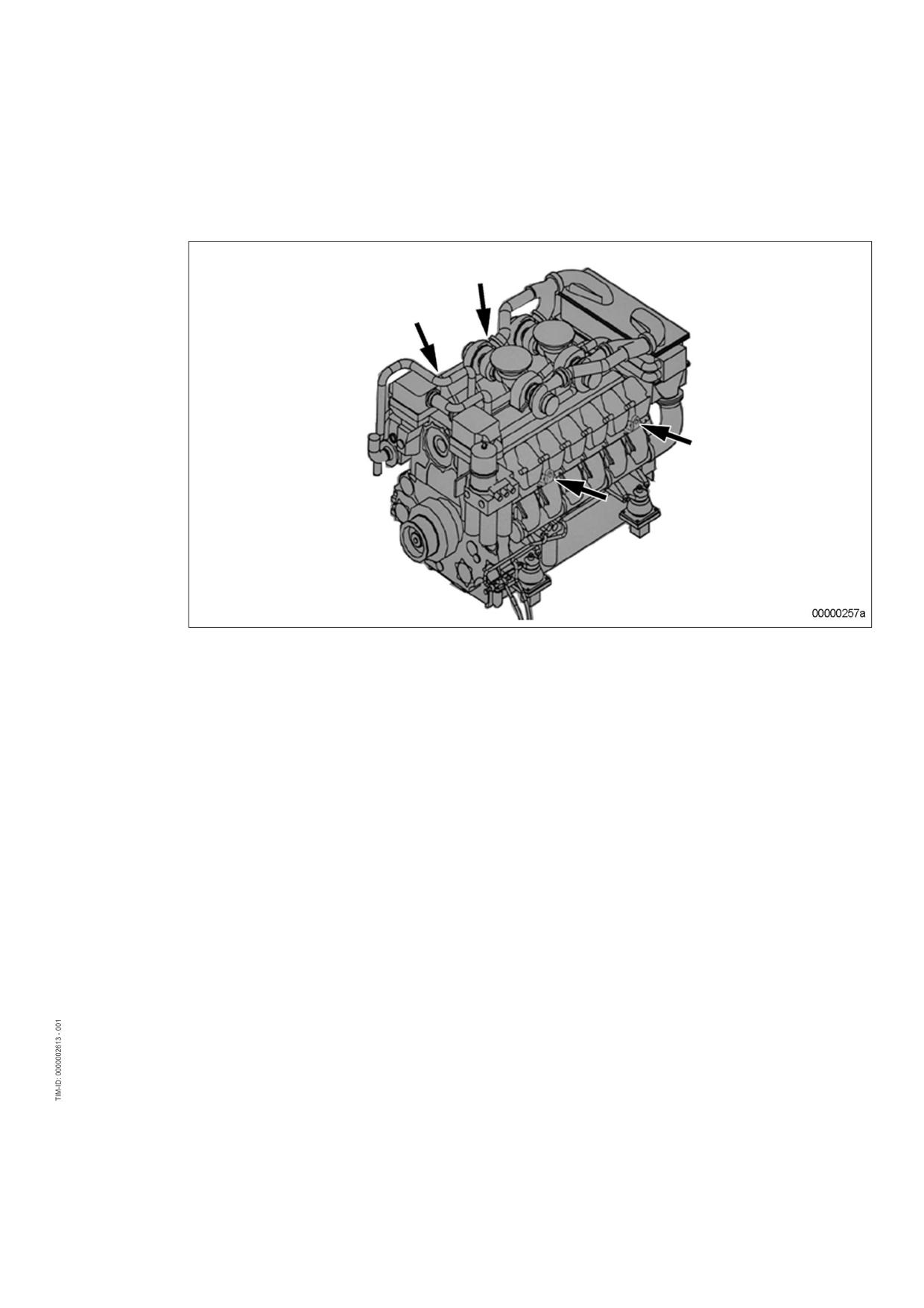
Lift the engine only with the lifting eyes provided.
Use only the transport and lifting equipment approved by MTU.
Take note of the engine center of gravity.
In the case of special packaging with aluminum foil, suspend the engine on the lifting eyes of the trans-
port pallet or transport with equipment for heavy loads (forklift truck).
Prior to transporting the engine, it is imperative to install transportation locking devices for crankshaft and
engine mounts.
Secure the engine against tilting during transportation. The engine must be especially secured against
slipping or tilting when going up or down inclines and ramps.
Setting the engine down after transport
Place the engine only on an even, firm surface.
Ensure appropriate consistency and load-bearing capacity of the ground or support surface.
Never place an engine on the oil pan, unless expressively authorized by MTU on a case-to-case basis to
do so.
MS150064/01E 2011-11 | Safety
|
9
1.4
Crankshaft transport locking device
Special tools, Material, Spare parts
Designation / Use
Part No.
Qty.
Torque wrench, 10-60 Nm
F30510423
1
Torque wrench, 60-320 Nm
F30047446
1
Engine oil
Transport locking device
Note:
The locking device protects the crankshaft bearings from shocks and vibration damage during engine
transport.
For installation and removal of the transport locking device, follow the instructions
below:
1.
The transport locking device must remain installed as long as possible during engine installation in order
to avoid damage.
2.
Starting or barring the engine is allowed only with the transport locking device removed. If the generator
is already mounted on the engine, ensure that the transport locking device of the generator is also re-
moved.
3.
Prior to every engine transport, the transport locking device must be reinstalled on both sides according
to the instructions.
4.
If the engine is to be moved together with the generator, the transport locking device for the generator
must also be installed.
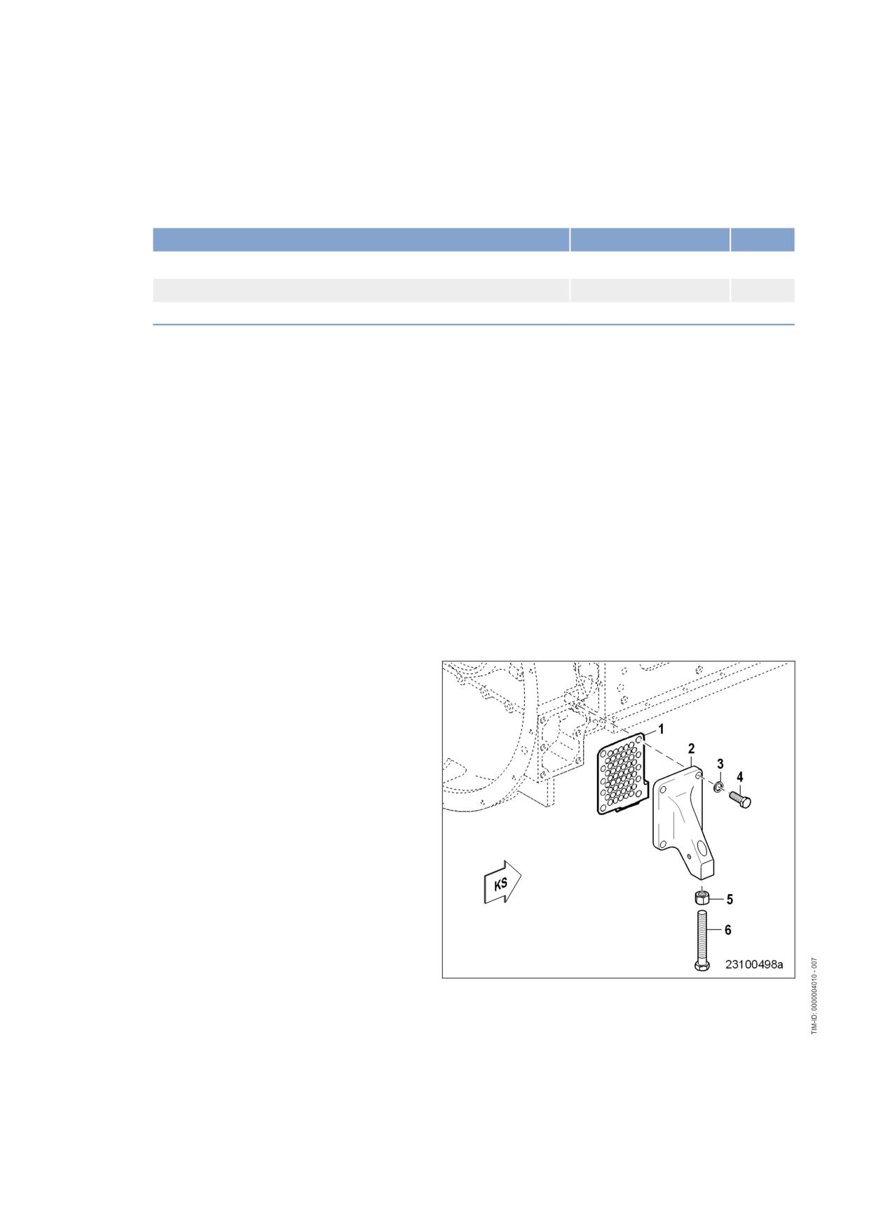
Removing guard plates and engine
mounting brackets (if applicable)
on driving end (KS)
1.
Remove screws (4) om both sides and take
off with washers (3), guard plates (1) and
engine mounting brackets (2).
2.
Store the removed parts of the transport
locking device carefully for possible reuse.
10 | Safety | MS150064/01E 2011-11
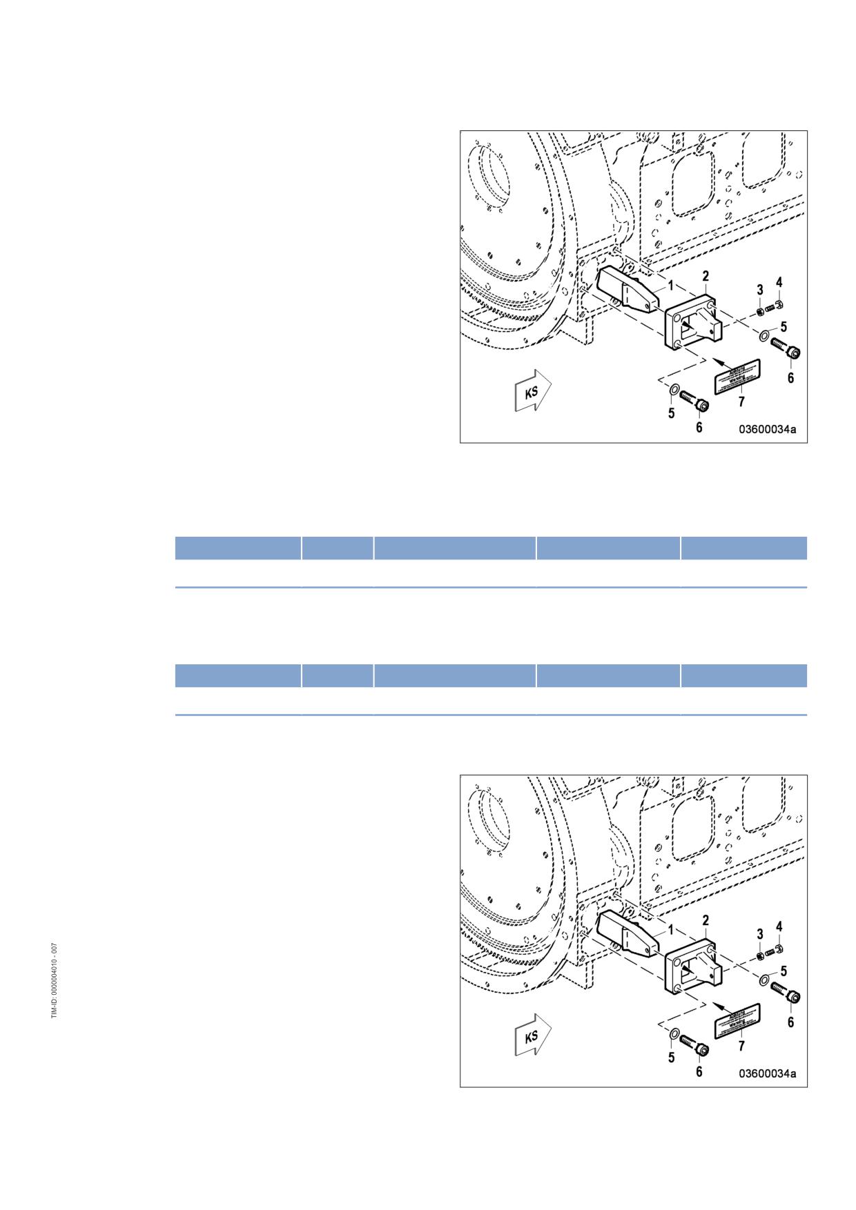
Fitting the transport locking device
on driving end (KS)
Note:
Always use the screws supplied with or installed in the transport locking device to secure it on the en-
gine.
1.
Secure the two plates (2) with screws (6) and washers (5) at the bores on both sides of the flywheel
housing and tighten to the specified tightening torque.
Name
Size
Type
Lubricant
Value/Standard
Screw
M16
Tightening torque
(Engine oil)
250 Nm +25 Nm
2.
Screw nut (3) onto screws (4) up to the end of the thread.
3.
Fit the locks (1) through the openings of plates (2) and fasten with the screws (4).
4.
Tighten screws (4) alternately with torque wrench to the specified tightening torque.
Name
Size
Type
Lubricant
Value/Standard
Screw
M10
Tightening torque
(Engine oil)
30 Nm +3 Nm
5.
Screw on nuts (3) of both screws (4) at plates (2) and secure.
6.
Fit label (7) to mark the engine as "Fitted with transport locking device".
Removing the transport locking
device from driving end (KS)
1.
Release the locknuts (3) on both sides of
the flywheel housing, remove screws (4)
and take off the two locks (1).
2.
Remove screws (6) with washers (5), label
(7) and plates (2)..
3.
Store the removed parts of the transport
locking device carefully for possible reuse.
MS150064/01E 2011-11 | Safety
|
11
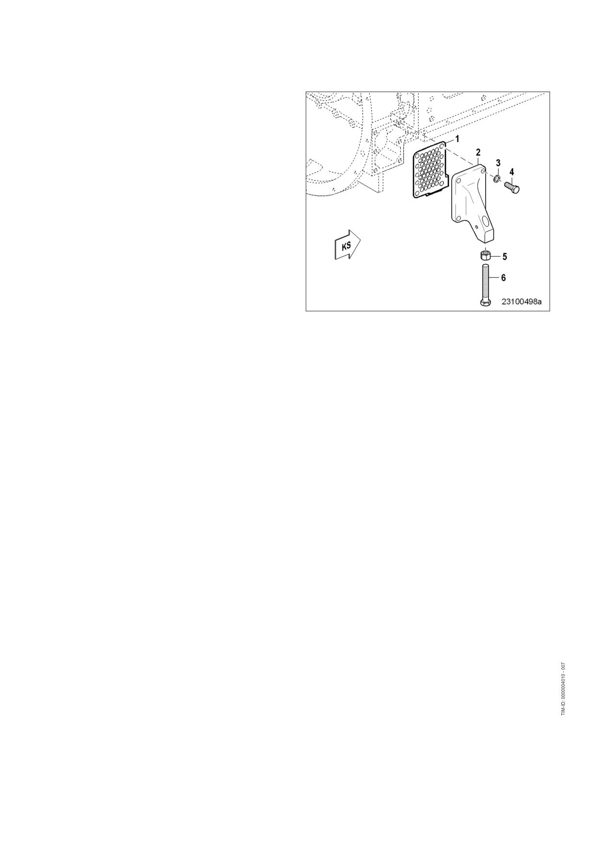
Installing guard plates and engine
mounting brackets (if applicable)
on driving end (KS)
Note:
Always use the screws supplied with the or
removed from the guard plates and engine
mounting brackets to secure them on the
engine.
1.
Install engine mounting brackets (2) on both
sides with guard plates (1) washers (3), and
screws (4).
2.
Tighten screws (4).
12 | Safety | MS150064/01E 2011-11
1.5
Safety regulations for startup and operation
Safety requirements for initial operation
Prior to initial operation of the unit, install the assembly or unit according to the specifications and check
the installation according to the MTU specifications.
Before putting the device or plant into operation, always ensure:
• that all maintenance and repair work is completed,
• that all loose parts have been removed from rotating machine components,
• that nobody is in the danger area of moving machine parts.
Immediately after putting the device or plant into operation, make sure that all control and display instru-
ments as well as the signaling and alarm systems work properly.
Safety requirements for operators
The procedures for cases of emergency must be practiced regularly.
The operator must be familiar with the control and display elements.
The operator must be familiar with the consequences of any operations performed.
During operation, the display instruments and monitoring units must be permanently observed with re-
gard to present operating status, violation of limit values and warning or alarm messages.
The following steps must be taken if a malfunction of the system is recognized or reported by the system:
• inform supervisor(s) in charge,
• analyze the message,
• if required, carry out emergency operations e.g. emergency engine stop.
Engine operation
The following conditions must be fulfilled before starting the engine:
• Wear ear protection.
• Ensure that the engine room is well ventilated.
• Do not inhale engine exhaust gases.
• Ensure that the exhaust system is free of leaks and that the gases are discharged to atmosphere.
• Mop up any leaked or spilt fluids and lubricants immediately or soak up with a suitable binding agent.
• Protect battery terminals, battery-charger terminals and cables against accidental contact.
• When the engine is running, never release coolant, oil, fuel, compressed-air or hydraulic lines.
Operation of electrical equipment
When electrical equipment is in operation, certain components of these appliances are electrically live.
Observe the safety instructions for these devices.
MS150064/01E 2011-11 | Safety
|
13
1.6
Explosion hazard when removing inspection port cover on
engine
DANGER
Explosion hazard due to oil vapors.
Risk of serious injury - danger to life!
• Allow the engine to cool down before opening the crankcase!
• Avoid open flames, electrical sparks and ignition sources.
Safety instructions
u Before starting maintenance work, allow the engine to cool down for at least 10 min. (danger of explosion
due to oil vapors).
14 | Safety | MS150064/01E 2011-11
1.7
Safety regulations for maintenance and repair work
Safety regulations for maintenance and repair work
Have maintenance and repair work carried out by qualified and authorized personnel only.
Allow the engine to cool down before starting maintenance work (risk of explosion of oil vapors).
Before starting work, relieve pressure in systems and compressed-air lines which are to be opened.
Take special care when removing ventilation or plug screws from the engine. Cover the screw or plug
with a rag to prevent fluids escaping under pressure.
Take special care when draining hot fluids ⇒ Risk of injury.
When changing the engine oil or working on the fuel system, ensure that the engine room is adequately
ventilated.
Allow the engine / system to cool down before starting to work.
Observe the maintenance and repair instructions.
Never carry out maintenance and repair work with the engine running unless expressly instructed to do
so.
Secure the engine against accidental starting.
Disconnect the battery when electrical starters are fitted.
Close the main valve on the compressed-air system and vent the compressed-air line when pneumatic
starters are fitted.
Disconnect the control equipment from the assembly or system.
Use only proper, calibrated tools. Observe the specified tightening torques during assembly/disassembly.
Carry out work only on assembles and/or units which are properly secured.
Never use lines for climbing.
Keep fuel injection lines and connections clean.
Always seal connections with caps or covers if a line is removed or opened.
Take care not to damage lines, in particular fuel lines, during maintenance and repair work.
Ensure that all retainers and dampers are installed correctly.
Ensure that all fuel injection and pressurized oil lines are installed with enough clearance to prevent con-
tact with other components. Do not place fuel or oil lines near hot components.
Do not touch elastomeric seals if they have carbonized or resinous appearance unless hands are proper-
ly protected.
Note cooling time for components which are heated for installation or removal ⇒ Risk of burning.
When working high on the engine, always use suitable ladders and work platforms. Make sure compo-
nents are placed on stable surfaces.
Observe special cleanness when conducting maintenance and repair work on the assembly or system.
After completion of maintenance and repair work, make sure that no loose objects are in/on the assem-
bly or system.
Before barring the engine, make sure that nobody is standing in the danger zone. Check that all guards
have been reinstalled and that all tools and loose parts have been removed after working on the engine.
The following additional instructions apply to starters with beryllium copper pinion:
• Breathing protection of filter class P2 must be applied during maintenance work to avoid health haz-
ards caused by the beryllium-containing pinion. Do not blow out the interior of the flywheel housing or
the starter with compressed air. Clean the flywheel housing inside with a class H dust extraction de-
vice as an additional measure.
MS150064/01E 2011-11 | Safety
|
15
Welding work
Never carry out welding work on the assembly, system, or engine-mounted units. Cover the engine when
welding in its vicinity.
Do not use the assembly or system as ground terminal.
Do not route the welding lead over or near the wiring harnesses of MTU systems. The welding current
may otherwise induce an interference voltage in the wiring harnesses which could conceivably damage
the electrical system.
Remove parts (e.g. exhaust pipes) which are to be welded from the engine beforehand.
Hydraulic installation and removal
Check the function and safe operating condition of tools and fixtures to be used. Use only the specified
devices for hydraulic removal/installation procedures.
Observe the max. permissible push-on pressure specified for the equipment.
Do not attempt to bend or apply force to lines.
Before starting work, pay attention to the following:
• Vent the hydraulic installation/removal tool, the pumps and the lines at the relevant points for the
equipment to be used (e.g. open vent plugs, pump until bubble-free air emerges, close vent plugs).
• For hydraulic installation, screw on the tool with the piston retracted.
• For hydraulic removal, screw on the tool with the piston extended.
For a hydraulic installation/removal tool with central expansion pressure supply, screw spindle into shaft
end until correct sealing is established.
During hydraulic installation and removal, ensure that nobody is standing in the immediate vicinity of the
component to be installed/removed.
Working on electrical/electronic assemblies
Always obtain the permission of the person in charge before commencing maintenance and repair work
or switching off any part of the electronic system required to do so.
De-energize the appropriate areas prior to working on assemblies.
Do not damage cabling during removal work. When reinstalling ensure that wiring is not damaged during
operation by contact with sharp objects, by rubbing against other components or by a hot surface.
Do not secure cables on lines carrying fluids.
Do not use cable binders to secure cables.
Always use connector pliers to tighten connectors.
Subject the device or system to a function check on completion of all repair work.
Store spare parts properly prior to replacement, i.e. protect them against moisture in particular. Pack de-
fective electronic components and assemblies in a suitable manner when dispatched for repair, i.e. par-
ticularly protected against moisture and impact and wrapped in antistatic foil if necessary.
Working with laser equipment
When working with laser equipment, always wear special laser-protection goggles ⇒ Heavily focused ra-
diation.
Laser equipment must be fitted with the protective devices necessary for safe operation according to
type and application.
16 | Safety | MS150064/01E 2011-11
For conducting light-beam procedures and measurement work, only the following laser devices must be
used:
• Laser devices of classes 1, 2 or 3A.
• Laser devices of class 3B, which have maximum output in the visible wavelength range (400 to 700
nm), a maximum output of 5 mW, and in which the beam axis and surface are designed to prevent
any risk to the eyes.
MS150064/01E 2011-11 | Safety
|
17
1.8
Fluids and lubricants, fire prevention and environmental
protection
Fire prevention
Rectify any fuel or oil leaks immediately; even splashes of oil or fuel on hot components can cause fires -
therefore always keep the engine in a clean condition. Do not leave cloths soaked with fluids and lubri-
cants lying on or near the assembly or unit. Do not store inflammable material near the assembly or unit.
Do not weld pipes and components carrying oil or fuel! Before welding, clean with a nonflammable fluid.
When starting the engine with an external power source, connect the ground lead last and remove it first.
To avoid sparks in the vicinity of the battery, connect the ground lead from the external power source to
the ground lead of the engine or to the ground terminal of the starter.
Always keep suitable firefighting equipment (fire extinguishers) at hand and familiarize yourself with their
use.
Noise
Noise can lead to an increased risk of accident if acoustic signals, warning shouts or noises indicating
danger are drowned.
Wear ear protectors in work areas with a sound pressure level in excess of 85 dB (A).
Environmental protection and disposal
Modification or removal of mechanical or electronic components or the installation of additional compo-
nents as well as the execution of calibration processes that might affect the emission characteristics of
the engine are prohibited by emission regulations. Emission control units/systems may only be main-
tained, exchanged or repaired if the components used for this purpose are approved by MTU or equiva-
lent components. Noncompliance with these guidelines might represent a violation of the Clean Air Act
and involves the termination of the operating license by the emission authorities. MTU does not accept
any liability for violations of the emission regulations. MTU will provide assistance and advice if emission-
relevant components are intended to be modified. The MTU Maintenance Schedules ensure the reliabili-
ty and performance of MTU engines and must be complied with over the entire life cycle of the engine.
Use only fuel of prescribed quality to comply with emission limit values.
Dispose of used fluids, lubricants and filters in accordance with local regulations.
Within the EU, batteries can be returned free of charge to MTU FN / MTU Onsite Energy where they are
subjected to proper recycling procedures.
Fluids and lubricants
Use only fluids and lubricants that have been tested and approved by MTU.
Keep fluids and lubricants in suitable, properly designated containers. When using fluids, lubricants and
other chemical substances, follow the safety instructions that apply to the product. Take special care
when using hot, chilled or caustic materials. When using flammable materials, avoid all sparks and do
not smoke.
Used oil
Used oil contains harmful combustion residues.
Rub barrier cream into hands.
Wash hands after contact with used oil.
18 | Safety | MS150064/01E 2011-11
Lead
• When working with lead or lead-containing compounds, avoid direct contact to the skin and do not
inhale lead vapors.
• Adopt suitable measures to avoid the formation of lead dust.
• Switch on extraction system.
• Wash hands after contact with lead or lead-containing substances.
Compressed air
Observe special safety precautions when working with compressed air:
• Pay special attention to the pressure level in the compressed air network and pressure vessel.
• Assemblies and equipment to be connected must either be designed for this pressure, or, if the per-
mitted pressure for the connecting elements is lower than the pressure required, a pressure reducing
valve and safety valve (set to permitted pressure) must form an intermediate connection.
• Hose couplings and connections must be securely attached.
• Wear goggles when blowing off components or blowing away chips.
• Provide the snout of the air nozzle with a protective disk (e.g. rubber disk).
• First shut off compressed air lines before compressed air equipment is disconnected from the supply
line, or before equipment or tool is to be replaced.
• Unauthorized use of compressed air, e.g. forcing flammable liquids (danger class AI, AII and B) out of
containers, results in a risk of explosion.
• Forcing compressed air into thin-walled containers (e.g. containers made of tin, plastic and glass) for
drying purposes or to check for leaks, results in a risk of bursting.
• Carry out leak test in accordance with the specifications.
Painting
• When carrying out painting work outside the spray stands provided with fume extraction systems, en-
sure that the area is well ventilated. Make sure that neighboring work areas are not impaired.
• No open flames.
• No smoking.
• Observe fire prevention regulations.
• Always wear a mask providing protection against paint and solvent vapors.
Liquid nitrogen
• Store liquid nitrogen only in small quantities and always in regulation containers without fixed covers.
• Avoid body contact (eyes, hands).
• Wear protective clothing, protective gloves, closed shoes and protective goggles / safety mask.
• Make sure that working area is well ventilated.
• Avoid all knocks and jars to the containers, fixtures or workpieces.
Acids and alkaline solutions
• When working with acids and alkalis, wear protective goggles or face mask, gloves and protective
clothing.
• If such solutions are spilled onto clothing, remove the affected clothing immediately.
• Rinse injured parts of the body thoroughly with clean water.
• Rinse eyes immediately with eyedrops or clean tap water.
MS150064/01E 2011-11 | Safety
|
19
1.9
Conventions for safety instructions in the text
DANGER
In the event of immediate danger.
Consequences: Death or serious injury
• Remedial action
WARNING
In the event of potentially dangerous situations.
Consequences: Death or serious injury
• Remedial action
CAUTION
In the event of dangerous situations.
Consequences: Minor injury or material damage
• Remedial action
Note:
This manual contains highlighted safety warnings in accordance with the US ANSI Z535 standard which
begin with one of the signal words listed above depending on the severity of the hazard.
Safety instructions
1.
Read and familiarize yourself with all safety notices before starting up or repairing the product.
2.
Pass on all safety instructions to your operating, maintenance, repair and transport personnel.
20 | Safety | MS150064/01E 2011-11
2 General Information
2.1
Engine side and cylinder designations
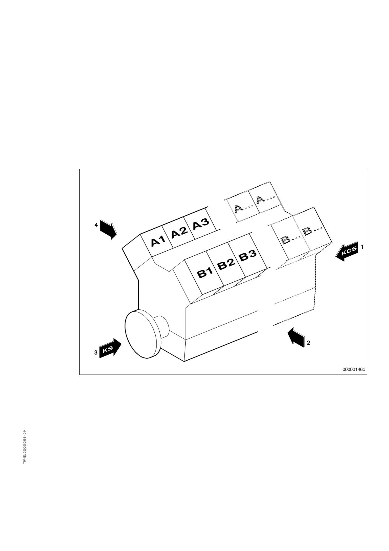
Engine sides are always designated as viewed from the driving end (KS).
The cylinders of the left engine side are designated "A" and those of the right side "B" (as per DIN ISO
1204). The cylinders of each bank are numbered consecutively, starting with No. 1 at the driving end of
the engine.
Other components are numbered in the same way, i.e. starting with No. 1 on driving end.
1 KGS = Free end
3 KS = Driving end
2 Right engine side
4 Left engine side
MS150064/01E 2011-11 | General Information | 21
2.2
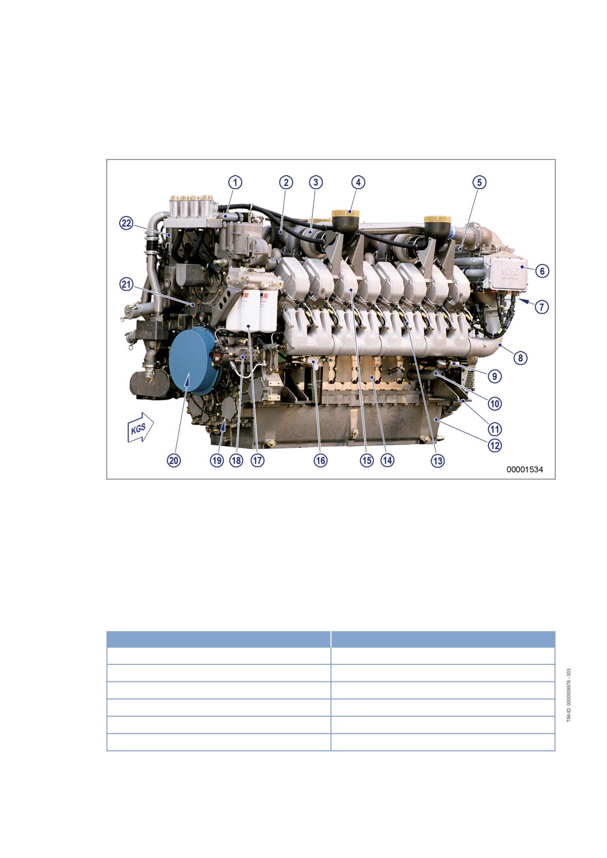
Engine layout
Illustration valid for 8/12/16V 4000 Gxy engines
1 Coolant line
8 Air supply
16 Fuel line (low pressure)
2 Exhaust system
9 Starting equipment
17 Lube oil filter
3 Exhaust turbocharger
10 Oil filler neck
18 Fuel pump (high pres-
4 Air intake
11 Mounting / support
sure)
5 Intercooler
12 Oil pan
19 Gear train
6 Engine governor
13 Fuel line (high pressure)
20 Running gear
7 PTO systems, driving end
14 Inspection port cover
21 Coolant system
and free end (coupling)
15 Cylinder head
22 Lube oil system
Engine model designation
Key to the engine model designations 8/12/16V 4000 Gxy
Designation
Meaning
8/12/16
Number of cylinders
V
Cylinder arrangement: V engine
4000
Series
G
Application
x
Application segment (2, 4, 6, 8)
y
Design index (1, 2,...)
22 | General Information | MS150064/01E 2011-11
3 Technical Data
3.1
12V 4000 engine data, continuous operation, variable 3B,
optimized fuel consumption
Explanation
Abbr.
Meaning
DL
Ref. value: Continuous power
BL
Ref. value: Fuel stop power
A
Design value
G
Guaranteed value
R
Guideline value
L
Limit value, up to which the engine can be operated without changes (e.g. of power set-
ting)
N
Not yet defined value
-
Not applicable
X
Applicable
REFERENCE CONDITIONS
Engine model
12V
12V
12V
4000 G21R
4000 G21R
4000 G41R
Application group
3B
3B
3B
Intake air temperature
°C
25
25
25
Charge-air coolant temperature
°C
55
55
55
Barometric pressure
mbar
1000
1000
1000
Site altitude above sea level
m
100
100
100
POWER-RELATED DATA (power ratings are net brake power as per ISO 3046)
Number of cylinders
12
12
12
Engine rated speed
A
rpm
1500
1800
1800
Continuous power ISO 3046 (10%
A
kW
1102
1246
1246
overload capability) (design power
DIN 6280, ISO 8528)
GENERAL CONDITIONS (for maximum power)
Number of cylinders
12
12
12
Intake air depression (new filter)
A
mbar
30
30
30
Intake air depression, max.
L
mbar
50
50
60
Exhaust pressure
A
mbar
30
30
30
Exhaust pressure, max.
L
mbar
51
51
51
MS150064/01E 2011-11 | Technical Data | 23
CONSUMPTION
Number of cylinders
12
12
12
Lube oil consumption after engine
R
% of B
0.5
0.5
0.5
run-in (B = hourly fuel consumption)
MODEL RELATED DATA (basic design)
Number of cylinders
12
12
12
Cylinder arrangement: V angle
Degrees (°)
90
90
90
Bore
mm
165
165
165
Stroke
mm
190
190
190
Displacement per cylinder
liter
4.06
4.06
4.06
Displacement, total
liter
48.7
48.7
65.0
Compression ratio
15.5
15.5
15.5
Number of inlet valves per cylinder
2
2
2
Number of exhaust valves per cylin-
2
2
2
der
Standard flywheel housing flange (en-
SAE
00
00
00
gine main PTO)
COMBUSTION AIR / EXHAUST GAS
Number of cylinders
12
12
12
Charge air pressure before cylinder,
R
bar ABS
2.4
2.8
2.8
BL
COOLING SYSTEM (HT circuit)
Number of cylinders
12
12
12
Coolant temperature (at engine outlet
A
°C
95
95
95
to cooling equipment)
Coolant temperature after engine,
R
°C
97
97
97
alarm
Coolant temperature after engine,
L
°C
99
99
99
shutdown
Coolant antifreeze content, max.
L
%
50
50
50
Pressure loss in external raw water
L
bar
0.7
0.7
0.7
system, max.
COOLING SYSTEM (LT circuit)
Number of cylinders
12
12
12
Coolant temperature before intercool-
A
°C
55
55
55
er (at engine inlet from cooling equip-
ment)
Coolant antifreeze content, max.
L
%
50
50
50
Pressure loss in external raw water
L
bar
0.7
0.7
0.7
system, max.
24 | Technical Data | MS150064/01E 2011-11
LUBE OIL SYSTEM
Number of cylinders
12
12
12
Lube oil temperature before engine,
R
°C
85
85
85
from
Lube oil operating temperature before
R
°C
95
95
95
engine, to
Lube oil temperature before engine,
R
°C
95
95
95
alarm
Lube oil operating pressure before
R
bar
5.0
5.0
5.0
engine, from
Lube oil operating pressure before
R
bar
6.0
6.0
6.0
engine, to
Lube oil pressure before engine,
R
bar
4.5
4.5
4.5
alarm
Lube oil pressure before engine,
L
bar
4.0
4.0
4.0
shutdown
FUEL SYSTEM
Number of cylinders
12
12
12
Fuel pressure at supply connection to
L
bar
-0.1
-0.1
-0.1
engine, min. (when engine is starting)
Fuel pressure at engine supply con-
L
bar
1.5
1.5
1.5
nection, max. (when engine is start-
ing)
GENERAL OPERATING DATA
Number of cylinders
12
12
12
Cold start capability: air temperature
R
°C
5
10
10
(w/o start aid, w/o preheating) (case
A)
Coolant preheating, preheating tem-
R
°C
32
32
32
perature (min.)
Firing speed, from
R
rpm
80
80
80
Firing speed, to
R
rpm
120
120
120
MS150064/01E 2011-11 | Technical Data | 25
CAPACITIES
Number of cylinders
12
12
12
Engine coolant capacity (without cool-
R
liter
160
160
160
ing equipment)
Charge-air coolant capacity, engine
R
liter
40
40
40
side
Engine oil at initial filling (standard oil
R
liter
260
260
260
system) (Option: max. operating incli-
nations)
Oil pan capacity at dipstick mark
L
liter
160
160
160
"min." (standard oil system) (Option:
max. operating inclinations)
Oil pan capacity at dipstick mark
L
liter
200
200
200
"max." (standard oil system) (Option:
max. operating inclinations)
WEIGHTS / MAIN DIMENSIONS
Number of cylinders
12
12
12
Engine weight, dry (basic engine con-
R
kg
5650
5650
5650
figuration acc. to scope of supply
specification)
ACOUSTICS
Number of cylinders
12
12
12
Exhaust noise, unsilenced, BL (free-
R
dB(A)
115
118
115
field sound pressure level Lp, 1m dis-
tance, ISO 6798, +3dB(A) tolerance)
Engine surface noise with attenuated
R
dB(A)
106
108
106
intake noise (filter), BL, (free-field
sound-pressure level Lp, 1m dis-
tance, ISO 6798+2dB(A) tolerance)
26 | Technical Data | MS150064/01E 2011-11
3.2
12V 4000 engine data, continuous operation, variable 3B,
emissions optimized w/o certificate
Explanation
Abbr.
Meaning
DL
Ref. value: Continuous power
BL
Ref. value: Fuel stop power
A
Design value
G
Guaranteed value
R
Guideline value
L
Limit value, up to which the engine can be operated without changes (e.g. of power set-
ting)
N
Not yet defined value
-
Not applicable
X
Applicable
REFERENCE CONDITIONS
Engine model
12V
12V
4000 G21R
4000 G41R
Application group
3B
3B
Intake air temperature
°C
25
25
Charge-air coolant temperature
°C
55
55
Barometric pressure
mbar
1000
1000
Site altitude above sea level
m
100
100
POWER-RELATED DATA (power ratings are net brake power as per ISO 3046)
Number of cylinders
12
12
Engine rated speed
A
rpm
1800
1800
Continuous power ISO 3046 (10% overload
A
kW
1246
1246
capability, design power DIN 6280, ISO
8528)
GENERAL CONDITIONS (for maximum power)
Number of cylinders
12
12
Intake air depression (new filter)
A
mbar
30
30
Intake air depression, max.
L
mbar
50
50
Exhaust pressure
A
mbar
30
30
Exhaust pressure, max.
L
mbar
51
51
CONSUMPTION
Number of cylinders
12
12
Lube oil consumption after engine run-in (B
R
% of B
0.5
0.5
= hourly fuel consumption)
MS150064/01E 2011-11 | Technical Data | 27
MODEL RELATED DATA (basic design)
Number of cylinders
12
12
Number of cylinders
12
12
Cylinder arrangement: V angle
Degrees (°)
90
90
Bore
mm
165
165
Stroke
mm
190
190
Displacement per cylinder
liter
4.06
4.06
Displacement, total
liter
48.7
48.7
Compression ratio
15.5
15.5
Number of inlet valves per cylinder
2
2
Number of exhaust valves per cylinder
2
2
Standard flywheel housing flange (engine
SAE
00
00
main PTO)
COMBUSTION AIR / EXHAUST GAS
Number of cylinders
12
12
Charge air pressure before cylinder, BL
R
bar ABS
3.1
3.1
COOLING SYSTEM (HT circuit)
Number of cylinders
12
12
Coolant temperature (at engine outlet to
A
°C
95
95
cooling equipment)
Coolant temperature after engine, alarm
R
°C
97
97
Coolant temperature after engine, shutdown
L
°C
99
99
Coolant antifreeze content, max.
L
%
50
50
Pressure loss in external raw water system,
L
bar
0.7
0.7
max.
COOLING SYSTEM (LT circuit)
Number of cylinders
12
12
Coolant temperature before intercooler (at
A
°C
55
55
engine inlet from cooling equipment)
Coolant antifreeze content, max.
L
%
50
50
Pressure loss in external raw water system,
L
bar
0.7
0.7
max.
LUBE OIL SYSTEM
Number of cylinders
12
12
Lube oil temperature before engine, from
R
°C
85
85
Lube oil operating temperature before en-
R
°C
95
95
gine, to
Lube oil temperature before engine, alarm
R
°C
95
95
Lube oil operating pressure before engine,
R
bar
5.0
5.0
from
28 | Technical Data | MS150064/01E 2011-11
Number of cylinders
12
12
Lube oil operating pressure before engine,
R
bar
6.0
6.0
to
Lube oil pressure before engine, alarm
R
bar
4.5
4.5
Lube oil pressure before engine, shutdown
L
bar
4.0
4.0
FUEL SYSTEM
Number of cylinders
12
12
Fuel pressure at supply connection to en-
L
bar
-0.1
-0.1
gine, min. (when engine is starting)
Fuel pressure at engine supply connection,
L
bar
1.5
1.5
max. (when engine is starting)
GENERAL OPERATING DATA
Number of cylinders
12
12
Cold start capability: air temperature (w/o
R
°C
5
10
start aid, w/o preheating) (case A)
Coolant preheating, preheating temperature
R
°C
32
32
(min.)
Firing speed, from
R
rpm
80
80
Firing speed, to
R
rpm
120
120
CAPACITIES
Number of cylinders
12
12
Engine coolant capacity (without cooling
R
liter
160
160
equipment)
Charge-air coolant capacity, engine side
R
liter
40
40
Engine oil at initial filling (standard oil sys-
R
liter
260
260
tem) (Option: max. operating inclinations)
Oil pan capacity at dipstick mark "min."
L
liter
160
160
(standard oil system) (Option: max. operat-
ing inclinations)
Oil pan capacity at dipstick mark "max."
L
liter
200
200
(standard oil system) (Option: max. operat-
ing inclinations)
WEIGHTS / MAIN DIMENSIONS
Number of cylinders
12
12
Engine weight, dry (basic engine configura-
R
kg
5650
5650
tion acc. to scope of supply specification)
MS150064/01E 2011-11 | Technical Data | 29
ACOUSTICS
Number of cylinders
12
12
Exhaust noise, unsilenced, BL (free-field
R
dB(A)
117
117
sound pressure level Lp, 1m distance, ISO
6798, +3dB(A) tolerance)
Engine surface noise with attenuated intake
R
dB(A)
107
107
noise (filter), BL, (free-field sound-pressure
level Lp, 1m distance, ISO 6798+2dB(A) tol-
erance)
30 | Technical Data | MS150064/01E 2011-11
3.3
12V 4000 engine data, continuous operation, variable 3B,
emissions optimized (TA-Luft)
Explanation
Abbr.
Meaning
DL
Ref. value: Continuous power
BL
Ref. value: Fuel stop power
A
Design value
G
Guaranteed value
R
Guideline value
L
Limit value, up to which the engine can be operated without changes (e.g. of power set-
ting)
N
Not yet defined value
-
Not applicable
X
Applicable
REFERENCE CONDITIONS
Engine model
12V
4000 G21R
Application group
3B
Intake air temperature
°C
25
Charge-air coolant temperature
°C
55
Barometric pressure
mbar
1000
Site altitude above sea level
m
100
POWER-RELATED DATA (power ratings are net brake power as per ISO 3046)
Number of cylinders
12
Engine rated speed
A
rpm
1500
Continuous power ISO 3046 (10% overload capabili-
A
kW
1102
ty) (design power DIN 6280, ISO 8528)
GENERAL CONDITIONS (for maximum power)
Number of cylinders
12
Intake air depression (new filter)
A
mbar
30
Intake air depression, max.
L
mbar
50
Exhaust pressure
A
mbar
30
Exhaust pressure, max.
L
mbar
51
CONSUMPTION
Number of cylinders
12
Lube oil consumption after engine run-in (B = hourly
R
% of B
0.5
fuel consumption)
MS150064/01E 2011-11 | Technical Data | 31
MODEL RELATED DATA (basic design)
Number of cylinders
12
Number of cylinders
12
Cylinder arrangement: V angle
Degrees (°)
90
Bore
mm
165
Stroke
mm
190
Displacement per cylinder
liter
4.06
Displacement, total
liter
48.7
Compression ratio
15.5
Number of inlet valves per cylinder
2
Number of exhaust valves per cylinder
2
Standard flywheel housing flange (engine main PTO)
SAE
00
COMBUSTION AIR / EXHAUST GAS
Number of cylinders
12
Charge air pressure before cylinder, BL
R
bar ABS
3.0
COOLING SYSTEM (HT circuit)
Number of cylinders
12
Coolant temperature (at engine outlet to cooling
A
°C
95
equipment)
Coolant temperature after engine, alarm
R
°C
97
Coolant temperature after engine, shutdown
L
°C
99
Coolant antifreeze content, max.
L
%
50
Pressure loss in external raw water system, max.
L
bar
0.7
COOLING SYSTEM (LT circuit)
Number of cylinders
12
Coolant temperature before intercooler (at engine in-
A
°C
55
let from cooling equipment)
Coolant antifreeze content, max.
L
%
50
Pressure loss in external raw water system, max.
L
bar
0.7
LUBE OIL SYSTEM
Number of cylinders
12
Lube oil temperature before engine, from
R
°C
85
Lube oil operating temperature before engine, to
R
°C
95
Lube oil temperature before engine, alarm
R
°C
95
Lube oil operating pressure before engine, from
R
bar
5.0
Lube oil operating pressure before engine, to
R
bar
6.0
Lube oil pressure before engine, alarm
R
bar
4.5
Lube oil pressure before engine, shutdown
L
bar
4.0
32 | Technical Data | MS150064/01E 2011-11
FUEL SYSTEM
Number of cylinders
12
Fuel pressure at supply connection to engine, min.
L
bar
-0.1
(when engine is starting)
Fuel pressure at engine supply connection, max.
L
bar
1.5
(when engine is starting)
GENERAL OPERATING DATA
Number of cylinders
12
Cold start capability: air temperature (w/o start aid, w/
R
°C
5
o preheating) (case A)
Coolant preheating, preheating temperature (min.)
R
°C
32
Firing speed, from
R
rpm
80
Firing speed, to
R
rpm
120
CAPACITIES
Number of cylinders
12
Engine coolant capacity (without cooling equipment)
R
liter
160
Charge-air coolant capacity, engine side
R
liter
40
Engine oil at initial filling (standard oil system) (Op-
R
liter
260
tion: max. operating inclinations)
Oil pan capacity at dipstick mark "min." (standard oil
L
liter
160
system) (Option: max. operating inclinations)
Oil pan capacity at dipstick mark "max." (standard oil
L
liter
200
system) (Option: max. operating inclinations)
WEIGHTS / MAIN DIMENSIONS
Number of cylinders
12
Engine weight, dry (basic engine configuration acc. to
R
kg
5650
scope of supply specification)
ACOUSTICS
Number of cylinders
12
Exhaust noise, unsilenced, BL (free-field sound pres-
R
dB(A)
115
sure level Lp, 1m distance, ISO 6798, +3dB(A) toler-
ance)
Engine surface noise with attenuated intake noise (fil-
R
dB(A)
106
ter), BL, (free-field sound-pressure level Lp, 1m dis-
tance, ISO 6798+2dB(A) tolerance)
MS150064/01E 2011-11 | Technical Data | 33
3.4
Final compression pressure
Final compression pressure
Final compression pressure at 120 rpm
24 bar to 28 bar
34 | Technical Data | MS150064/01E 2011-11
3.5
Firing order
Firing order
Number of cylin-
Firing order
ders
8V
A1-B4-A4-A2-B3-A3-B2-B1
12V
A1-B2-A5-B4-A3-B1-A6-B5-A2-B3-A4-B6
16 V
A1-A7-B4-B6-A4-B8-A2-A8-B3-B5-A3-A5-B2-A6-B1-B7
20 V
A1-B5-A8-B7-A5-B2-A7-B10-A2-B3-A10-B6-A3-B4-A6-B9-A4-B1-A9-B8
MS150064/01E 2011-11 | Technical Data | 35
3.6
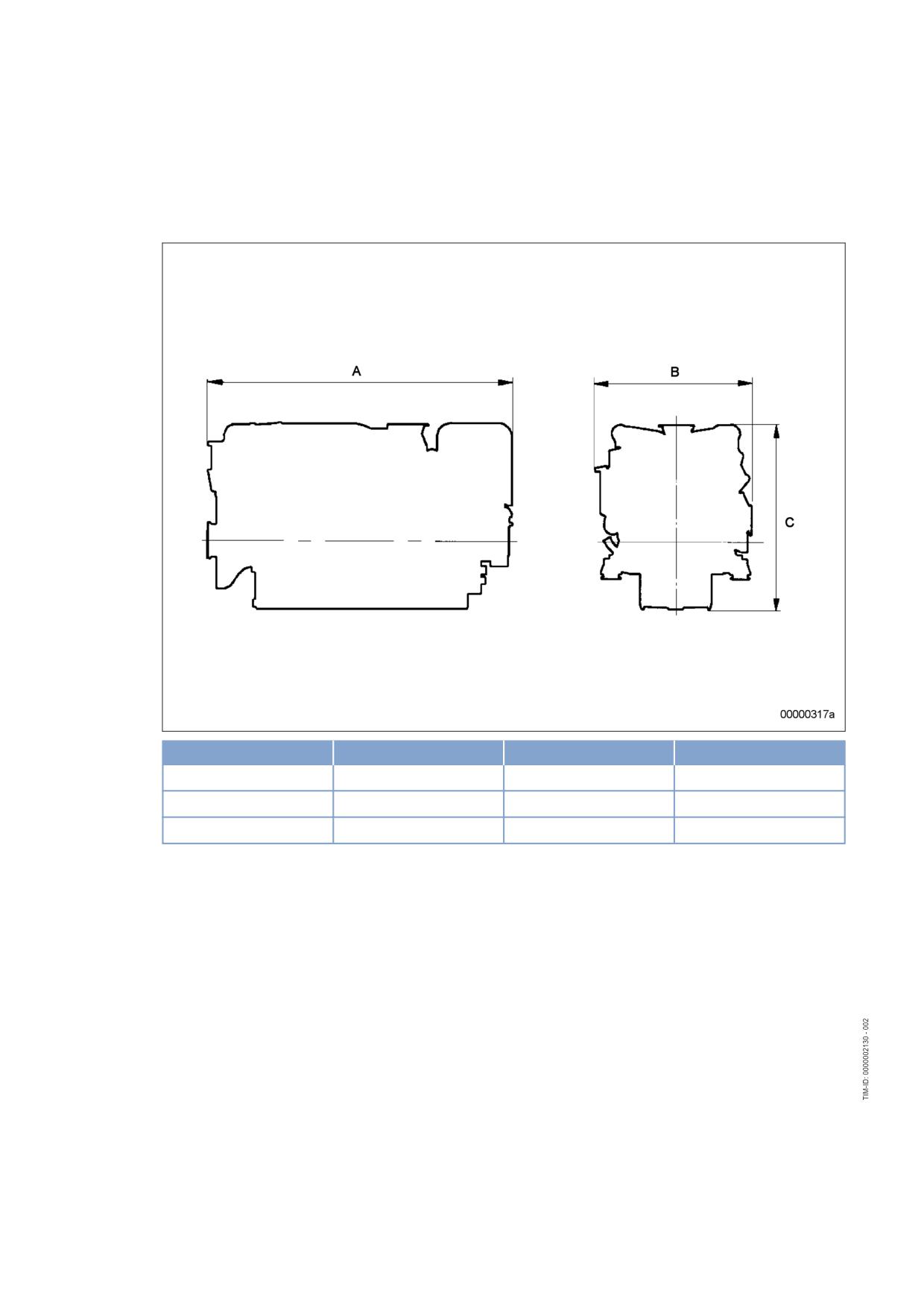
Engine - Main dimensions
Engine - Main dimensions
Engine model
Length (A)
Width (B)
Height (C)
8 V 4000 Gxy
approx. 1940 mm
approx. 1550 mm
approx. 1760 mm
12 V 4000 Gxy
approx. 2410 mm
approx. 1550 mm
approx. 1760 mm
16 V 4000 Gxy
approx. 2880 mm
approx. 1550 mm
approx. 1760 mm
36 | Technical Data | MS150064/01E 2011-11
4 Operation
4.1
Putting the engine into operation after extended out-of-
service periods (>3 months)
Preconditions
☑ Engine is stopped and starting disabled.
☑ MTU Fluids and Lubricants Specification (A001061/..) is available.
Putting the engine into operation after extended out-of-service-periods (>3 months)
Item
Task
Engine
Depreserve (→ MTU Fluids and Lubricants Specification A001061/..).
Valve Gear
Lubricate valve gear (→ Page 72);
Lube oil system
Check oil level (→ Page 98);
Fuel prefilter
Prime (→ Page 90).
Fuel prefilter, pressure
Align adjustable pointer with position of pressure indicator (→ Page 86).
gauge
Fuel system
Vent (→ Page 83).
Cooling system
If engine is out of service for more than one year, change engine coolant
(→ Page 106);
Change charge-air coolant (→ Page 114).
Cooling system
Check engine coolant level (→ Page 105);
Check charge-air coolant level (→ Page 113).
Cooling system
Preheat coolant with preheating unit.
ECU
Check plug-in connections (→ Page 127).
Monitoring equipment
Carry out lamp test (see manufacturer's documentation).
Engine/generator control
Switch ON;
system
Select operating mode, e.g. MANUAL OPERATION, AUTOMATIC OPER-
ATION.
MS150064/01E 2011-11 | Operation | 37
4.2
Putting the engine into operation after scheduled out-of-
service-period
Preconditions
☑ Engine is stopped and starting disabled.
Putting the engine into operation
Item
Task
Lube oil system
Check oil level (→ Page 98);
Cooling system
Check engine coolant level (→ Page 105);
Check charge-air coolant level (→ Page 113).
Cooling system
Preheat coolant with preheating unit.
Fuel prefilter
Drain (→ Page 87).
Monitoring equipment
Carry out lamp test (see manufacturer's documentation).
Engine/generator control
Switch ON;
system
Select operating mode, e.g. MANUAL OPERATION, AUTOMATIC OPER-
ATION.
38 | Operation | MS150064/01E 2011-11
4.3
Start engine in manual mode (testing mode)
Preconditions
☑ Generator (if provided) not connected to network.
☑ External start interlock is not activated.
DANGER
Unguarded rotating and moving engine components.
Risk of serious injury - danger to life!
• Before barring or starting the engine, make sure that nobody is in the danger zone.
WARNING
Engine noise above 85 dB (A).
Risk of damage to hearing!
• Wear ear protectors.
Preparation
Item
Task
Operating mode selector
Change to manual mode.
switch (if provided)
Preheating pump (if provid-
Switch ON.
ed)
Starting the engine
Item
Task
Switchgear cabinet, control
If coolant temperature is
panel etc. (depending on
•
> 40 °C (with preheating equipment), or
manufacturer)
•
> 5 °C (without preheating equipment):
Press start button.
• Automatic starting sequence is performed;
• Engine speed display instrument indicates increasing crankshaft speed;
• After the starting sequence is completed, engine is running at rated
speed.
Connect generator to network (if provided), run engine to reach operating
temperature )
Item
Task
Switchgear cabinet, control
Close the generator circuit breaker.
panel etc. (depending on
manufacturer)
Engine
Apply full load only after engine has reached operating temperature (cool-
ant temperature approx. 75 °C).
MS150064/01E 2011-11 | Operation | 39
4.4
Starting the engine in emergency situations (override mode)
CAUTION
Safety functions and engine shutdown alarms will be disregarded.
Serious damage to plant!
• Initiate emergency start only in emergency situations.
Preparation
Item
Task
Operating mode switch
Set to emergency mode.
Starting the engine in emergency situations
Item
Task
Control cabinet
Actuate switch/button for ECU override input.
Control cabinet
• Automatic starting procedure is performed; any safety functions and
alarms leading to engine shutdown are disregarded;
• Tachometer indicates increasing crankshaft speed;
• Engine is running at rated speed when the starting sequence is com-
pleted.
Connecting the generator (if fitted) to mains
Item
Task
Control cabinet
If generator is not connected to mains: Close generator circuit breaker.
Engine
Operate engine at rated power.
40 | Operation | MS150064/01E 2011-11
4.5
Operational checks
DANGER
Unguarded rotating and moving engine components.
Risk of serious injury - danger to life!
• Take special care when working on a running engine.
WARNING
Engine noise above 85 dB (A).
Risk of damage to hearing!
• Wear ear protectors.
Operational checks
Item
Task
Control and display panels
Check indicated operating parameters (speed, temperatures, pressures).
Engine under load
Check engine/system and lines for leak-tightness, perform maintenance
work on lines showing leakage while motor is turned off (exhaust mani-
Engine at nominal speed
folds and turbocharger turbine housing may be glowing with heat. If maxi-
mum exhaust temperatures are within the limit, restricted engine operation
is not required);
Check for abnormal running noises and vibrations.
HP pump
Check relief bore (→ Page 76).
Fuel prefilter
Check if suction-side pressure indicated at the fuel prefilter pressure
gauge is within the limit (→ Page 86).
Exhaust system
Check exhaust color (→ Page 48).
Intercooler
Check condensate drain(s) for water discharge and obstruction
(→ Page 92).
Air filter
Check signal ring position of service indicator (→ Page 95);
Replace air filter (→ Page 93), if the signal ring is completely visible in the
service indicator control window.
Engine coolant pump
Check relief bore (→ Page 111).
Charge-air coolant pump
Check relief bore (→ Page 120).
Compressed-air system (if
Check operating pressure at pressure gauge.
installed)
Fill compressed-air tank to maximum pressure.
Drain condensate from compressed-air tank, pressure drop must not ex-
ceed 1 bar.
MS150064/01E 2011-11 | Operation | 41
4.6
Stop engine in manual mode (testing mode)
Preconditions
☑ Generator (if provided) not connected to network.
☑ Engine is running in manual mode.
CAUTION
Stopping the engine when it is running at full load causes extreme stress to the engine.
Risk of overheating, damage to components!
• Before stopping the engine, operate it at idle speed until operating temperatures decrease and
stable values are indicated.
Preparing the generator drive (only with generator breaker)
Item
Task
Engine
After opening the generator breaker (if provided), allow to cool down off-
load for approx. 5 minutes.
Preparing the pump drive (diesel-mechanical/diesel-electric)
Item
Task
Engine
Allow to cool down for approx. 5 minutes at reduced engine speed. Ob-
serve natural resonance of engine (installation-dependent)!
Stopping the engine
Item
Task
Switchgear cabinet, control
Press stop button.
panel etc. (depending on
• Automatic stopping sequence is performed;
manufacturer)
• Engine is stopped.
After stopping the engine
Item
Task
Coolant pump
Allow to run on for sufficient time after stopping.
42 | Operation | MS150064/01E 2011-11
4.7
Emergency stop
CAUTION
An emergency stop causes extreme stress to the engine.
Risk of overheating, damage to components!
• Initiate emergency stop only in emergency situations.
Emergency stop from LOP
Item
Task
EMERGENCY STOP but-
Press.
ton
• Engine is stopped by switching off power supply to ECU;
• Signalization (e.g. by horn, flashing lamp) is released.
After emergency stop from LOP
Item
Task
Switching cabinet, control
Press button for alarm acknowledgement.
panel etc. (depending on
• Audible and visual signalization stops.
manufacturer)
MS150064/01E 2011-11 | Operation | 43
4.8
After stopping the engine - Engine remains ready for
operation
After stopping the engine
Item
Action
Engine/generator/pump
Select operating mode, e.g. MANUAL, AUTOMATIC OPERATION.
control
44 | Operation | MS150064/01E 2011-11
4.9
After stopping the engine - putting the engine out of service
Preconditions
☑ MTU Fluids and Lubricants Specifications (A001061/..) is available.
After stopping the engine
Item
Task
Cooling system
Drain engine coolant (→ Page 107);
Drain charge-air coolant (→ Page 115) if:
• freezing temperatures are expected and the engine is to remain out of
service for an extended period and coolant has no antifreeze additive;
• the engine room is not heated;
• the coolant is not maintained at a suitable temperature;
• the antifreeze concentration is insufficient for the engine-room tempera-
ture;
• antifreeze concentration is 50 % and engine-room temperature is below
-40°C.
Engine/generator/pump
Switch OFF.
controller
Air intake and exhaust sys-
If the engine is to remain out of service for more than 1 week, seal the
tem
engine's air and exhaust sides. If the engine is to remain out of service for
more than 1 month, preserve engine (→ MTU Fluids and Lubricants Speci-
fications A001061/.. ).
MS150064/01E 2011-11 | Operation | 45
4.10
Plant - Cleaning
Preconditions
☑ Engine is stopped and starting disabled.
☑ Operating voltage is not applied.
Special tools, Material, Spare parts
Designation / Use
Part No.
Qty.
Steam jet cleaner
-
1
Cleaner (Hakupur 312)
30390
1
WARNING
Compressed air
Risk of injury!
• Do not direct compressed-air jet at persons.
• Wear protective goggles / safety mask and ear protectors.
WARNING
Water jet.
Risk of injury and scalding!
• Do not direct water jet at persons.
• Wear protective clothing, gloves, and goggles / safety mask.
CAUTION
Excessive reaction time of cleaning agents on components.
Damage to component!
• Observe manufacturer's instructions.
• Wear protective clothing, gloves, and goggles / safety mask.
Note:
There is a risk of damaging sensors with compressed air.
Plant - Cleaning
1.
Carry out plant cleaning only in areas where an appropriate oil separator is provided (environmental pro-
tection).
2.
Prior to putting the cleaning unit into operation, read the Operating Instructions of the water/steam jet unit
carefully and observe the safety precautions.
3.
For external cleaning with high-pressure jet, use a flat-mouth nozzle only.
4.
Carry out external cleaning as follows:
a) Remove coarse dirt.
b) Spray on cleaner sparingly and leave it for 1 to 5 minutes.
c) Use the high-pressure jet to remove the loosened dirt.
d) During external cleaning of the plant with water/steam-jet units, the pressure of the high-pressure jet
(cleaning jet) must not exceed 50 bar. A minimum distance between spray nozzle and plant of 1 m
must be observed. The temperature of the cleaning medium must not exceed 80 °C.
46 | Operation | MS150064/01E 2011-11
5 Maintenance
5.1
Maintenance task reference table [QL1]
The maintenance tasks and intervals for this product are defined in the Maintenance Schedule. The
Maintenance Schedule is a stand-alone publication.
The task numbers in this table provide reference to the maintenance tasks specified in the Maintenance
Schedule.
Task
Maintenance tasks
W0500
Check engine oil level
(→ Page 98)
W0501
Visually inspect engine for leaks and general condition
(→ Page 41)
W0502
Check intercooler drain (if fitted)
(→ Page 92)
W0503
Check signal ring position of service indicator on air filter
(→ Page 95)
W0504
Check HP fuel pump weep holes
(→ Page 41)
W0505
Check relief bores of coolant pump(s)
(→ Page 111)
W0506
Check engine for abnormal running noises, exhaust color
(→ Page 41)
and vibrations
W0507
Drain water and contaminants from fuel prefilter (if fitted)
(→ Page 41)
W0508
Check reading on differential pressure gauge of fuel prefilter
(→ Page 41)
(if fitted)
W0534
Carry out test run, minimum duration: until steady-state tem-
(→ Page 65)
perature is reached, no less than 1/3 load (monthly)
W1001
Replace fuel filter or fuel filter element
(→ Page 84)
W1002
Check valve clearance
(→ Page 73)
W1003
Check drive belt condition and tension, replace if necessary
(→ Page 121)
W1005
Replace air filter
(→ Page 93)
W1006
Replace fuel injectors
(→ Page 77)
W1008
Replace engine oil filter at each oil change or when the time
(→ Page 102)
limit (years) is reached, at the latest
W1009
Check layer thickness of oil residue, clean and replace filter
(→ Page 103)
sleeve (if fitted)
W1011
Perform endoscopic inspection of combustion chambers
(→ Page 66)
W1046
Crankcase breather: Replace filter or filter element
(→ Page 70)
Table 1: Maintenance task reference table [QL1]
MS150064/01E 2011-11 | Maintenance | 47
6 Troubleshooting
6.1
Troubleshooting
Engine does not turn when starter is actuated
Component
Probable cause
Task
Battery
Low or defective
Charge or replace (see manufacturer's
documentation).
Cable connections defective
Check if cable connections are proper-
ly secured (see manufacturer's docu-
mentation).
Starter (electric)
Engine wiring or starter defective
Check cable connections for secure
seating,
Contact Service.
Starter (compressed
Cabling on starting valve or starter de-
Check cable connections for secure
air)
fective
seating,
Contact Service.
Engine wiring
Defective
Check (→ Page 125).
Engine/generator
Secure seating of assemblies or con-
Perform visual inspection (see manu-
control system
nectors not provided
facturer's documentation).
Engine Governor
Plug-in connections are loose
Check plug connections (→ Page 127).
Engine
Running gear blocked (engine cannot
Contact Service.
be barred manually)
Engine turns but does not fire
Component
Probable cause
Task
Starter (electric)
Poor rotation by starter: Battery low or
Charge or replace battery (see manu-
defective
facturer's documentation).
Starter (compressed
Poor rotation by starter: Air pressure
Check compressed air system.
air)
too low
Engine wiring
Defective
Check (→ Page 125).
Fuel system
Not vented
Vent fuel system (→ Page 83).
Engine Governor
Defective
Contact Service.
Engine fires unevenly
Component
Probable cause
Task
Fuel injection equip-
Injector defective
Replace (→ Page 77).
ment
Engine wiring
Defective
Check (→ Page 125).
Fuel system
Not vented
Vent fuel system (→ Page 83).
Engine Governor
Defective
Contact Service.
48 | Troubleshooting | MS150064/01E 2011-11
Engine does not reach nominal speed
Component
Probable cause
Task
Fuel supply
Fuel prefilter clogged
Replace (→ Page 90).
Easy-change fuel filter clogged
Replace (→ Page 84).
Air supply
Air filter clogged
Check signal ring position of service in-
dicator (→ Page 95).
Fuel injection equip-
Injector defective
Replace (→ Page 77).
ment
Engine wiring
Defective
Check (→ Page 125).
Engine
Overloaded
Contact Service.
Engine speed not steady
Component
Probable cause
Task
Fuel injection equip-
Injector defective
Replace (→ Page 77).
ment
Speed sensor
Defective
Contact Service.
Fuel system
Not vented
Vent fuel system (→ Page 83).
Engine Governor
Defective
Contact Service.
Charge-air temperature too high
Component
Probable cause
Task
Engine coolant
Incorrect coolant concentration
Check (MTU test kit).
Intercooler
Contaminated
Contact Service.
Engine room
Air-intake temperature too high
Check fans and air supply / ventilation
ducts.
Charge air pressure too low
Component
Probable cause
Task
Air supply
Air filter clogged
Check signal ring position of service in-
dicator (→ Page 95).
Intercooler
Contaminated
Contact Service.
Exhaust turbocharger
Defective
Contact Service.
Coolant leaks on intercooler
Component
Probable cause
Task
Intercooler
Leaking, major coolant discharge
Contact Service.
Exhaust gas black
Component
Probable cause
Task
Air supply
Air filter clogged
Check signal ring position of service in-
dicator (→ Page 95).
Fuel injection equip-
Injector defective
Replace (→ Page 77).
ment
Engine
Overloaded
Contact Service.
MS150064/01E 2011-11 | Troubleshooting | 49
Exhaust gas blue
Component
Probable cause
Task
Engine oil
Too much engine oil in the engine
Drain engine oil (→ Page 99).
Oil separator of crankcase breather
Replace (→ Page 70).
contaminated
Exhaust turbocharg-
Defective
Contact Service.
er, cylinder head, pis-
ton rings, cylinder lin-
er
Exhaust gas white
Component
Probable cause
Task
Engine
Not at operating temperature
Run engine to reach operating temper-
ature.
Fuel system
Water in fuel
Check fuel system on fuel prefilter.
Drain fuel prefilter (→ Page 87).
Intercooler
Leaking
Contact Service.
50 | Troubleshooting | MS150064/01E 2011-11
6.2
Fault messages on engine governor
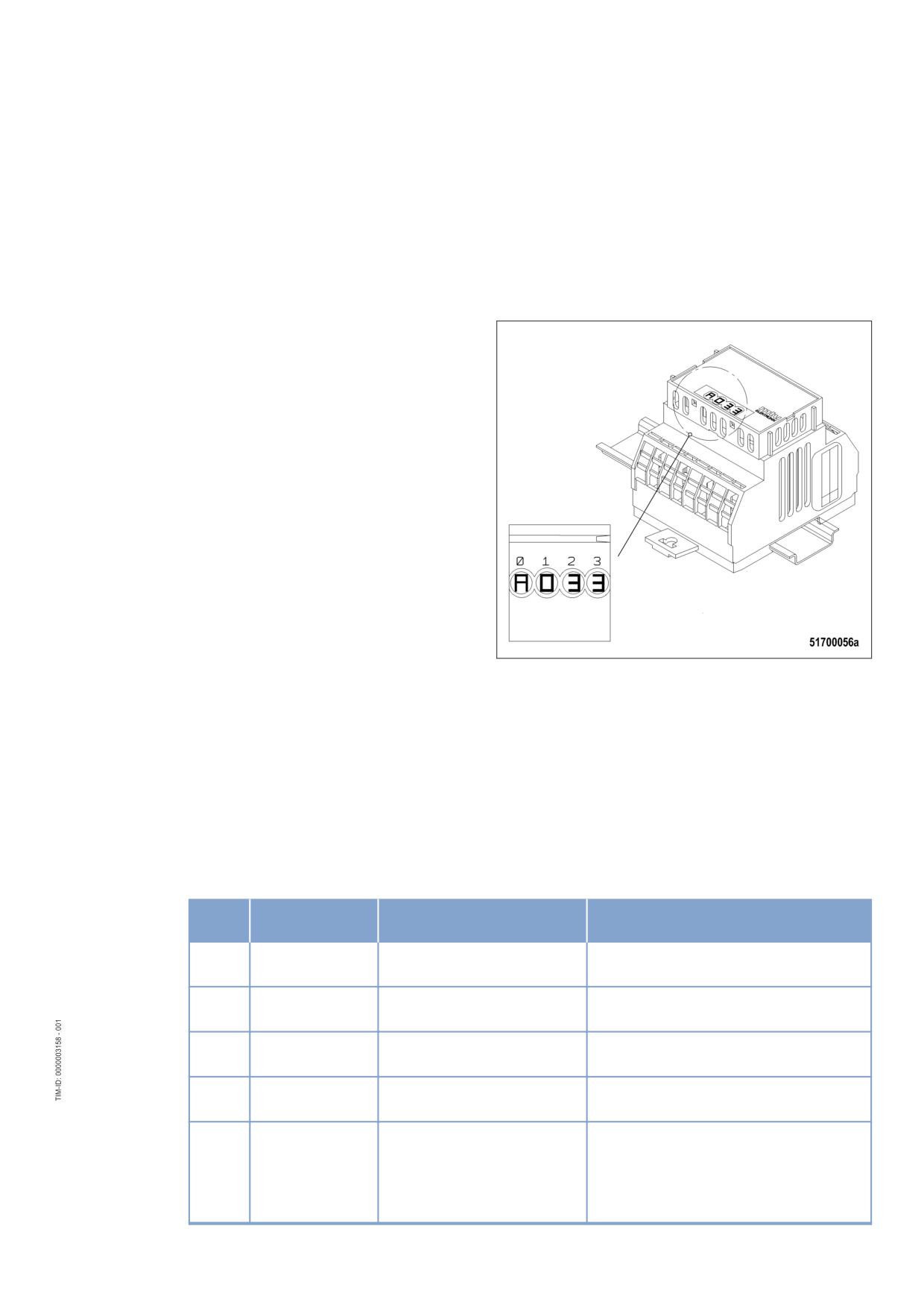
The engine governor generates alarms which are indicated in different ways depending on the equip-
ment configuration:
• as four-digit code on a PIM
• as alarm text on a display
• as four-digit code on a dialog PC
The four-digit code consists of one letter and three figures:
• The letter encodes when the fault occurred the last time:
A = currently present
B = within the last operating hour
C = one to four operating hours ago
D = four to twelve operating hours ago
Alarms that occurred more than twelve hours ago are deleted automatically.
• The three figures encode the fault itself as listed in the table below.
Alarms can also be caused by defective sensors / actuators. If troubleshooting in accordance with the
following table is not successful, contact Service to have the sensors / actuators checked and, if re-
quired, replaced.
Fault
Alarm text
Meaning
Task
code
005
L1 T-CHARGE
Charge-air temperature too
Reduce power. Change over to idle and
AIR
high (1st limit value)
contact Service.
006
L2 T-CHARGE
Charge-air temperature too
Reduce power. Change over to idle and
AIR
high (2nd limit value)
contact Service.
009
L1 T-INTER-
Charge-air coolant tempera-
Reduce power. Change over to idle and
COOLER
ture too high (1st limit value)
contact Service.
015
L1 P-LUBE OIL
Lube oil pressure too low (1st
Check engine-oil level and top up, if re-
limit value)
quired (→ Page 98).
016
L2 P-LUBE OIL
Lube oil pressure too low (2nd
1. Check engine-oil level and top up, if
limit value)
required (→ Page 98).
2. Try to re-start the engine
automatic engine shutdown
(→ Page 39).
3. Contact Service.
MS150064/01E 2011-11 | Troubleshooting | 51
Fault
Alarm text
Meaning
Task
code
023
L1 COOLANT
Engine coolant level too low
Check coolant level and top up, if re-
LEVEL
quired (→ Page 105).
024
L2 COOLANT
Engine coolant level too low
Check coolant level and top up, if re-
LEVEL
quired (→ Page 105).
030
ENGINE OVER-
Engine overspeed; automatic
1. Acknowledge alarm.
SPEED
engine shutdown
2. Try to re-start the engine
(→ Page 39).
3. Contact Service.
044
L1 LEVEL IN-
Charge-air coolant level too
Check coolant level and top up, if re-
TERCOOLER
low (1st limit value)
quired (→ Page 113).
045
L2 LEVEL IN-
Charge-air coolant level too
1. Check coolant level and top up, if re-
TERCOOLER
low (2nd limit value)
quired (→ Page 113).
2. If fault occurs repeatedly: Contact
Service.
051
L1 T-LUBE OIL
Lube oil temperature too high
Reduce power. Change over to idle and
(1st limit value)
contact Service.
052
L2 T-LUBE OIL
Lube oil temperature too high
1. Reduce power. Change over to idle
(2nd limit value)
and contact Service.
2. If fault occurs repeatedly: Contact
Service.
065
L1 P-FUEL
Fuel supply pressure too low
1. Check fuel lines for leaks; repair de-
(1st limit value)
fective lines.
2. Clean fuel prefilter (→ Page 85);
3. Flush fuel prefilter (→ Page 88);
4. Replace filter element of fuel prefilter
(→ Page 90);
5. Replace fuel filter (→ Page 84);
6. If fault is not rectified: Contact Serv-
ice.
066
L2 P-FUEL
Fuel supply pressure too low
1. Check fuel lines for leaks; repair de-
(2nd limit value)
fective lines.
2. Clean fuel prefilter (→ Page 85);
3. Flush fuel prefilter (→ Page 88);
4. Replace filter element of fuel prefilter
(→ Page 90);
5. Replace fuel filter (→ Page 84);
6. If fault is not rectified: Contact Serv-
ice.
067
L1 T-COOLANT
Coolant temperature too high
Reduce power. Change over to idle and
(1st limit value) warning
contact Service.
068
L2 T-COOLANT
Coolant temperature too high
1. Allow the engine to cool down.
(2nd limit value)
2. Check coolant cooler (elements etc.)
and clean contaminated parts (see
automatic engine shutdown
manufacturer's documentation).
3. Re-start the engine (→ Page 39);
4. If fault occurs repeatedly: Contact
Service.
069
L1 T-EXTERN 1
Violation of first limit for exter-
(Depending on the corresponding meas-
nal temperature channel 1
uring point, which is read via CAN bus)
52 | Troubleshooting | MS150064/01E 2011-11
Fault
Alarm text
Meaning
Task
code
070
L2 T-EXTERN 1
Violation of second limit for
(Depending on the corresponding meas-
external temperature channel
uring point, which is read via CAN bus)
1
071
L1 T-EXTERN 2
Violation of first limit for exter-
(Depending on the corresponding meas-
nal temperature channel 2
uring point, which is read via CAN bus)
072
L2 T-EXTERN 2
Violation of second limit for
(Depending on the corresponding meas-
external temperature channel
uring point, which is read via CAN bus)
2
073
L1 P-EXTERN 1
Violation of first limit for exter-
(Depending on the corresponding meas-
nal pressure channel 1
uring point, which is read via CAN bus)
074
L2 P-EXTERN 1
Violation of second limit for
(Depending on the corresponding meas-
external pressure channel 1
uring point, which is read via CAN bus)
075
L1 P-EXTERN 2
Violation of first limit for exter-
(Depending on the corresponding meas-
nal pressure channel 2
uring point, which is read via CAN bus)
076
L2 P-EXTERN 2
Violation of second limit for
(Depending on the corresponding meas-
external pressure channel 2
uring point, which is read via CAN bus)
077
LIM EXT.COOL-
Alarm from external coolant
(Depending on the corresponding meas-
ANT LEV.
level monitoring
uring point, which is read via CAN bus)
078
LIM INTER-
Alarm from external charge-air
(Depending on the corresponding meas-
COOLER LEV.
coolant level monitoring
uring point, which is read via CAN bus)
079
L Bin-EXTERN 3
Alarm from external binary
(Depending on the corresponding meas-
channel 3
uring point, which is read via CAN bus)
080
L Bin-EXTERN 4
Alarm from external binary
(Depending on the corresponding meas-
channel 4
uring point, which is read via CAN bus)
081
RAIL LEAKAGE
HP fuel system leaking, sys-
Contact Service.
tem contains air
082
RAIL PRESSURE
Pressure in HP fuel system
Contact Service.
HIGH
exceeds specified value;
Solenoid valve of HP fuel con-
trol block jamming or wiring to
solenoid valve defective
083
RAIL PRESSURE
Pressure in HP fuel system
Contact Service.
LOW
lower than the specified value;
HP fuel control block defective
or system leaking
NOTE:
With very large generators
having a run-out time of more
than > 20 sec this alarm is not
a relevant fault.
089
ENGINE SPEED
Engine speed lower than 200
Re-start the engine (→ Page 39);
LOW
rpm;
automatic engine shutdown
090
IDLE SPEED
Idle speed not reached within
Note further alarms.
LOW
a specified period;
Termination of starting proce-
dure.
MS150064/01E 2011-11 | Troubleshooting | 53
Fault
Alarm text
Meaning
Task
code
091
RUN UP SPEED
Run-up speed not reached
Note further alarms.
LOW
within a specified period;
Termination of starting proce-
dure.
092
START SPEED
Starter speed not reached
Note further alarms.
LOW
within a specified period;
Termination of starting proce-
dure.
093
PREHEAT
Coolant preheating tempera-
Check preheating pump / preheating sys-
TEMP. LIMIT2
ture too low during start (2nd
tem (see manufacturer's documentation).
limit value);
Termination of starting proce-
dure (depending on project
design)
094
PREHEAT
Coolant preheating tempera-
Check preheating pump / preheating sys-
TEMP. LIMIT1
ture too low during start (1st
tem (see manufacturer's documentation).
limit value)
100
EDM NOT VALID
Check sum error of measur-
If fault occurs repeatedly: Contact Serv-
ing-point data in EDM
ice.
101
IDM NOT VALID
Check sum error of measur-
If fault occurs repeatedly: Contact Serv-
ing-point data in IDM
ice.
102
INVALID FUEL
Check sum error of accumu-
If fault occurs repeatedly: Contact Serv-
CONS. 1
lated fuel consumption data in
ice.
EDM (redundant data record
1)
103
INVALID FUEL
Check sum error of accumu-
If fault occurs repeatedly: Contact Serv-
CONS. 2
lated fuel consumption data in
ice.
EDM (redundant data record
2)
104
OP HOURS1
Check sum error of hour me-
If fault occurs repeatedly: Contact Serv-
NOT VALID
ter data in EDM
ice.
105
OP HOURS2
Check sum error of hour me-
If fault occurs repeatedly: Contact Serv-
NOT VALID
ter data in IDM
ice.
106
ERR REC1 NOT
Check sum error of fault mem-
If fault occurs repeatedly: Contact Serv-
VALID
ory in EDM (redundant data
ice.
record 1)
107
ERR REC2 NOT
Check sum error of fault mem-
If fault occurs repeatedly: Contact Serv-
VALID
ory in EDM (redundant data
ice.
record 2)
118
L1 SUPPLY
Supply voltage too low (1st
Check engine governor supply voltage.
VOLT. LOW
limit value)
119
L2 SUPPLY
Supply voltage too low (2nd
Check engine governor supply voltage.
VOLT. LOW
limit value)
120
L1 SUPPLY
Supply voltage too high (1st
Check engine governor supply voltage.
VOLT. HIGH
limit value)
54 | Troubleshooting | MS150064/01E 2011-11
Fault
Alarm text
Meaning
Task
code
121
L2 SUPPLY
Supply voltage too high (2nd
Check engine governor supply voltage.
VOLT. HIGH
limit value);
If engine was stopped: Start engine
automatic engine shutdown
(→ Page 39).
(depending on project design)
122
L1 T-ELEC-
Temperature in engine gover-
1. Improve engine room ventilation.
TRONIC
nor housing too high (1st limit
2. Reduce engine power. Change over
value)
to idle and contact Service.
134
15V POS ECU
Electronic equipment defec-
Contact Service.
DEFECT
tive;
automatic engine shutdown
136
15V NEG ECU
Electronic equipment defec-
Contact Service.
DEFECT
tive;
automatic engine shutdown
137
L1 5V BUFFER
Power supply for pressure
1. Disconnect connectors X2 and X3
TEST
sensors defective.
from engine governor. If alarm does
not disappear: Contact Service.
2. Check wiring (pressure sensors).
3. Contact Service.
138
SENSORPO-
Power supply for pressure
1. Disconnect connectors X2 and X3
WERDEFECT
sensors defective.
from engine governor. If alarm does
not disappear: Contact Service.
2. Check wiring (pressure sensors).
3. Contact Service.
139
L1 TE BUFFER
Internal electronic fault (tem-
Contact Service.
TEST
perature sensors)
140
TE BUF. ECU
Internal electronic fault (tem-
Contact Service.
DEFECT
perature sensors)
142
BANK1 ECU DE-
Internal electronic fault;
Contact Service.
FECT
Engine does not start
144
BANK2 ECU DE-
Internal electronic fault;
Contact Service.
FECT
Engine does not start
145
15V_GOOD ECU
Electronic equipment defec-
Contact Service.
DEFECT
tive;
automatic engine shutdown
146
L1 AD-TEST1
A/D-converter supply voltage
Contact Service.
SUPPLY
too low
147
AD-TEST1 ECU
Electronic equipment defec-
Contact Service.
DEFECT
tive;
automatic engine shutdown
148
L1 AD-TEST2
A/D-converter supply voltage
Contact Service.
SUPPLY
too low
149
AD-TEST2 ECU
Electronic equipment defec-
Contact Service.
DEFECT
tive;
automatic engine shutdown
150
L1 AD-TEST3
A/D-converter supply voltage
Contact Service.
SUPPLY
too low
MS150064/01E 2011-11 | Troubleshooting | 55
Fault
Alarm text
Meaning
Task
code
151
AD-TEST3 ECU
Electronic equipment defec-
Contact Service.
DEFECT
tive;
automatic engine shutdown
170
MI MODULE
Module in maintenance pre-
Contact Service.
FAIL
dictor either defective or miss-
ing
171
MI NOT ACTIVE
Maintenance predictor no
Contact Service.
more activated
173
MODULE WRITE
EEPROM write limit reached
Contact Service.
LIMIT
180
CAN1 NODE
At least one device not detect-
1. Check wiring (CAN bus).
LOST
ed on Default CAN bus
2. Contact Service.
181
CAN2 NODE
At least one device not detect-
1. Check wiring (CAN bus).
LOST
ed on Redundant CAN bus
2. Contact Service.
182
CAN WRONG
Consistency error in CAN pa-
Contact Service.
PARAMETERS
rameters
183
CAN NO PU-DA-
Error during project design da-
Contact Service.
TA
ta download in engine gover-
nor.
184
CAN PU-DATA
Error during project design da-
Contact Service.
EE-FAIL
ta download in EEPROMs
185
CAN LESS MAIL-
Error during CAN initialization.
Contact Service.
BOXES
186
CAN1 BUS OFF
Severe fault on Default CAN
Contact Service.
bus;
automatic change-over to Re-
dundant CAN bus
187
CAN1 ERROR
Light fault on Default CAN bus
(none)
PASSIVE
(e.g. short-time overload)
188
CAN2 BUS OFF
Severe fault on Redundant
Contact Service.
CAN bus;
automatic change-over to De-
fault CAN bus
189
CAN2 ERROR
Light fault on Redundant CAN
(none)
PASSIVE
bus (e.g. short-time overload)
201
SD T-COOLANT
Sensor defect (coolant tem-
1. Check wiring.
perature)
2. Contact Service.
202
SD T-FUEL
Sensor defect (Fuel tempera-
1. Check wiring.
ture)
2. Contact Service.
203
SD T-CHARGE
Sensor defect (charge-air
1. Check wiring.
AIR
temperature)
2. Contact Service.
205
SD T-COOLANT
Sensor defect (charge-air
1. Check wiring.
INTERC.
coolant temperature)
2. Contact Service.
208
SD P-CHARGE
Sensor defect (charge-air
1. Check wiring.
AIR
pressure)
2. Contact Service.
56 | Troubleshooting | MS150064/01E 2011-11
Fault
Alarm text
Meaning
Task
code
211
SD P-LUBE OIL
Sensor defect (lube oil pres-
1. Check wiring.
sure)
2. Contact Service.
215
SD P-RAIL FUEL
Sensor defect (common rail
1. Check wiring.
pressure);
2. Contact Service.
HP controller in emergency
mode
216
SD T-LUBE OIL
Sensor defect (lube oil tem-
1. Check wiring.
perature)
2. Contact Service.
220
SD COOLANT
Sensor defect (coolant level)
1. Check wiring.
LEVEL
2. Contact Service.
223
SD LEVEL IN-
Sensor defect (charge-air
1. Check wiring.
TERCOOLER
coolant level)
2. Contact Service.
229
SD ENG.SPEED
Sensor defect (crankshaft
1. Check wiring.
SENSORS
speed) and sensor defect
2. Contact Service.
(camshaft speed)
230
SD CRANK-
Sensor defect (crankshaft
1. Check wiring.
SHAFT SPEED
speed)
2. Contact Service.
231
SD CAMSHAFT
Sensor defect (camshaft
1. Check wiring.
SPEED
speed)
2. Contact Service.
240
SD P-FUEL
Sensor defect (fuel pressure)
1. Check wiring.
2. Contact Service.
245
SD POWER
Sensor defect (engine gover-
Contact Service.
SUPPLY
nor operating voltage)
246
SD T-ELEC-
Sensor defect (temperature in
Contact Service.
TRONIC
engine governor)
250
SD CAN SPEED
Sensor defect (CAN nominal
1. Check speed transmitter.
DEMAND
speed demand)
2. Check wiring (CAN bus).
3. Contact Service.
266
SD SPEED DE-
Sensor defect (analog nomi-
1. Check speed transmitter.
MAND AN.
nal speed demand)
2. Check wiring.
3. Contact Service.
267
SD
Sensor defect (analog speed
1. Check speed transmitter.
SP.DEM.TEST
demand);
2. Check wiring.
BENCH
3. Contact Service.
NOTE:
Only used in test-stand opera-
tion.
270
SD SPEED DE-
Sensor defect (frequency in-
1. Check speed transmitter.
MAND FI1
put for speed demand);
2. Check wiring.
3. Contact Service.
271
SD T-EXTERN 1
External device defective
Contact Service.
(CAN T-EXTERN 1)
272
SD T-EXTERN 2
External device defective
Contact Service.
(CAN T-EXTERN 2)
273
SD P-EXTERN 1
External device defective
Contact Service.
(CAN P-EXTERN 1)
274
SD P-EXTERN 2
External device defective
Contact Service.
(CAN P-EXTERN 2)
MS150064/01E 2011-11 | Troubleshooting | 57
Fault
Alarm text
Meaning
Task
code
275
SD EXT.COOL-
External coolant-level monitor-
Contact Service.
ANT LEVEL
ing defective (CAN)
276
SD INTERCOOL-
External charge-air coolant-
Contact Service.
ER LEVEL
level monitoring defective
(CAN)
277
SD BIN-EXTERN
External device defective
Contact Service.
3
(CAN BIN-EXTERN 3)
278
SD BIN-EXTERN
External device defective
Contact Service.
4
(CAN BIN-EXTERN 4)
301
TIMING CYLIN-
Injection timing fault cylinder
If fault occurs repeatedly: Contact Serv-
DER A1
A1
ice.
302
TIMING CYLIN-
Injection timing fault cylinder
If fault occurs repeatedly: Contact Serv-
DER A2
A2
ice.
303
TIMING CYLIN-
Injection timing fault cylinder
If fault occurs repeatedly: Contact Serv-
DER A3
A3
ice.
304
TIMING CYLIN-
Injection timing fault cylinder
If fault occurs repeatedly: Contact Serv-
DER A4
A4
ice.
305
TIMING CYLIN-
Injection timing fault cylinder
If fault occurs repeatedly: Contact Serv-
DER A5
A5
ice.
306
TIMING CYLIN-
Injection timing fault cylinder
If fault occurs repeatedly: Contact Serv-
DER A6
A6
ice.
307
TIMING CYLIN-
Injection timing fault cylinder
If fault occurs repeatedly: Contact Serv-
DER A7
A7
ice.
308
TIMING CYLIN-
Injection timing fault cylinder
If fault occurs repeatedly: Contact Serv-
DER A8
A8
ice.
309
TIMING CYLIN-
Injection timing fault cylinder
If fault occurs repeatedly: Contact Serv-
DER A9
A9
ice.
310
TIMING CYLIN-
Injection timing fault cylinder
If fault occurs repeatedly: Contact Serv-
DER A10
A10
ice.
311
TIMING CYLIN-
Injection timing fault cylinder
If fault occurs repeatedly: Contact Serv-
DER B1
B1
ice.
312
TIMING CYLIN-
Injection timing fault cylinder
If fault occurs repeatedly: Contact Serv-
DER B2
B2
ice.
313
TIMING CYLIN-
Injection timing fault cylinder
If fault occurs repeatedly: Contact Serv-
DER B3
B3
ice.
314
TIMING CYLIN-
Injection timing fault cylinder
If fault occurs repeatedly: Contact Serv-
DER B4
B4
ice.
315
TIMING CYLIN-
Injection timing fault cylinder
If fault occurs repeatedly: Contact Serv-
DER B5
B5
ice.
316
TIMING CYLIN-
Injection timing fault cylinder
If fault occurs repeatedly: Contact Serv-
DER B6
B6
ice.
317
TIMING CYLIN-
Injection timing fault cylinder
If fault occurs repeatedly: Contact Serv-
DER B7
B7
ice.
318
TIMING CYLIN-
Injection timing fault cylinder
If fault occurs repeatedly: Contact Serv-
DER B8
B8
ice.
319
TIMING CYLIN-
Injection timing fault cylinder
If fault occurs repeatedly: Contact Serv-
DER B9
B9
ice.
58 | Troubleshooting |
MS150064/01E 2011-11
Fault
Alarm text
Meaning
Task
code
320
TIMING CYLIN-
Injection timing fault cylinder
If fault occurs repeatedly: Contact Serv-
DER B10
B10
ice.
321
WIRING CYLIN-
Faulty wiring to solenoid valve
1. Check wiring.
DER A1
cylinder A1;
2. Contact Service.
Misfiring
322
WIRING CYLIN-
Faulty wiring to solenoid valve
1. Check wiring.
DER A2
cylinder A2;
2. Contact Service.
Misfiring
323
WIRING CYLIN-
Faulty wiring to solenoid valve
1. Check wiring.
DER A3
cylinder A3;
2. Contact Service.
Misfiring
324
WIRING CYLIN-
Faulty wiring to solenoid valve
1. Check wiring.
DER A4
cylinder A4;
2. Contact Service.
Misfiring
325
WIRING CYLIN-
Faulty wiring to solenoid valve
1. Check wiring.
DER A5
cylinder A5;
2. Contact Service.
Misfiring
326
WIRING CYLIN-
Faulty wiring to solenoid valve
1. Check wiring.
DER A6
cylinder A6;
2. Contact Service.
Misfiring
327
WIRING CYLIN-
Faulty wiring to solenoid valve
1. Check wiring.
DER A7
cylinder A7;
2. Contact Service.
Misfiring
328
WIRING CYLIN-
Faulty wiring to solenoid valve
1. Check wiring.
DER A8
cylinder A8;
2. Contact Service.
Misfiring
329
WIRING CYLIN-
Faulty wiring to solenoid valve
1. Check wiring.
DER A9
cylinder A9;
2. Contact Service.
Misfiring
330
WIRING CYLIN-
Faulty wiring to solenoid valve
1. Check wiring.
DER A10
cylinder A10;
2. Contact Service.
Misfiring
331
WIRING CYLIN-
Faulty wiring to solenoid valve
1. Check wiring.
DER B1
cylinder B1;
2. Contact Service.
Misfiring
332
WIRING CYLIN-
Faulty wiring to solenoid valve
1. Check wiring.
DER B2
cylinder B2;
2. Contact Service.
Misfiring
333
WIRING CYLIN-
Faulty wiring to solenoid valve
1. Check wiring.
DER B3
cylinder B3;
2. Contact Service.
Misfiring
MS150064/01E 2011-11 | Troubleshooting | 59
Fault
Alarm text
Meaning
Task
code
334
WIRING CYLIN-
Faulty wiring to solenoid valve
1. Check wiring.
DER B4
cylinder B4;
2. Contact Service.
Misfiring
335
WIRING CYLIN-
Faulty wiring to solenoid valve
1. Check wiring.
DER B5
cylinder B5;
2. Contact Service.
Misfiring
336
WIRING CYLIN-
Faulty wiring to solenoid valve
1. Check wiring.
DER B6
cylinder B6;
2. Contact Service.
Misfiring
337
WIRING CYLIN-
Faulty wiring to solenoid valve
1. Check wiring.
DER B7
cylinder B7;
2. Contact Service.
Misfiring
338
WIRING CYLIN-
Faulty wiring to solenoid valve
1. Check wiring.
DER B8
cylinder B8;
2. Contact Service.
Misfiring
339
WIRING CYLIN-
Faulty wiring to solenoid valve
1. Check wiring.
DER B9
cylinder B9;
2. Contact Service.
Misfiring
340
WIRING CYLIN-
Faulty wiring to solenoid valve
1. Check wiring.
DER B10
cylinder B10;
2. Contact Service.
Misfiring
341
OPEN_LOAD
Disconnection in wiring to sol-
1. Check wiring.
CYL. A1
enoid valve cylinder A1;
2. Contact Service.
Misfiring
342
OPEN_LOAD
Disconnection in wiring to sol-
1. Check wiring.
CYL. A2
enoid valve cylinder A2;
2. Contact Service.
Misfiring
343
OPEN_LOAD
Disconnection in wiring to sol-
1. Check wiring.
CYL. A3
enoid valve cylinder A3;
2. Contact Service.
Misfiring
344
OPEN_LOAD
Disconnection in wiring to sol-
1. Check wiring.
CYL. A4
enoid valve cylinder A4;
2. Contact Service.
Misfiring
345
OPEN_LOAD
Disconnection in wiring to sol-
1. Check wiring.
CYL. A5
enoid valve cylinder A5;
2. Contact Service.
Misfiring
346
OPEN_LOAD
Disconnection in wiring to sol-
1. Check wiring.
CYL. A6
enoid valve cylinder A6;
2. Contact Service.
Misfiring
347
OPEN_LOAD
Disconnection in wiring to sol-
1. Check wiring.
CYL. A7
enoid valve cylinder A7;
2. Contact Service.
Misfiring
60 | Troubleshooting | MS150064/01E 2011-11
Fault
Alarm text
Meaning
Task
code
348
OPEN_LOAD
Disconnection in wiring to sol-
1. Check wiring.
CYL. A8
enoid valve cylinder A8;
2. Contact Service.
Misfiring
349
OPEN_LOAD
Disconnection in wiring to sol-
1. Check wiring.
CYL. A9
enoid valve cylinder A9;
2. Contact Service.
Misfiring
350
OPEN_LOAD
Disconnection in wiring to sol-
1. Check wiring.
CYL. A10
enoid valve cylinder A10;
2. Contact Service.
Misfiring
351
OPEN_LOAD
Disconnection in wiring to sol-
1. Check wiring.
CYL. B1
enoid valve cylinder B1;
2. Contact Service.
Misfiring
352
OPEN_LOAD
Disconnection in wiring to sol-
1. Check wiring.
CYL. B2
enoid valve cylinder B2;
2. Contact Service.
Misfiring
353
OPEN_LOAD
Disconnection in wiring to sol-
1. Check wiring.
CYL. B3
enoid valve cylinder B3;
2. Contact Service.
Misfiring
354
OPEN_LOAD
Disconnection in wiring to sol-
1. Check wiring.
CYL. B4
enoid valve cylinder B4;
2. Contact Service.
Misfiring
355
OPEN_LOAD
Disconnection in wiring to sol-
1. Check wiring.
CYL. B5
enoid valve cylinder B5;
2. Contact Service.
Misfiring
356
OPEN_LOAD
Disconnection in wiring to sol-
1. Check wiring.
CYL. B6
enoid valve cylinder B6;
2. Contact Service.
Misfiring
357
OPEN_LOAD
Disconnection in wiring to sol-
1. Check wiring.
CYL. B7
enoid valve cylinder B7;
2. Contact Service.
Misfiring
358
OPEN_LOAD
Disconnection in wiring to sol-
1. Check wiring.
CYL. B8
enoid valve cylinder B8;
2. Contact Service.
Misfiring
359
OPEN_LOAD
Disconnection in wiring to sol-
1. Check wiring.
CYL. B9
enoid valve cylinder B9;
2. Contact Service.
Misfiring
360
OPEN_LOAD
Disconnection in wiring to sol-
1. Check wiring.
CYL. B10
enoid valve cylinder B10;
2. Contact Service.
Misfiring
361
POWER STAGE
Defect in engine governor
Contact Service.
FAIL 1
(solenoid valve power stage)
362
POWER STAGE
Defect in engine governor
Contact Service.
FAIL 2
(solenoid valve power stage)
MS150064/01E 2011-11 | Troubleshooting | 61
Fault
Alarm text
Meaning
Task
code
363
STOP POWER
Solenoid valve or wiring or en-
1. Check wiring.
STAGE 1
gine governor defective
2. Try to re-start the engine
(→ Page 39).
automatic engine shutdown
3. Contact Service.
364
STOP POWER
Solenoid valve or wiring or en-
1. Check wiring.
STAGE 2
gine governor defective
2. Try to re-start the engine
(→ Page 39).
automatic engine shutdown
3. Contact Service.
365
STOP MV-WIR-
Solenoid-valve wiring faulty;
1. Check wiring.
ING
2. Try to re-start the engine
automatic engine shutdown
(→ Page 39).
3. Contact Service.
381
TRAN.OUT1
Binary transistor output
Contact Service.
PLANT DEF
plant 1 defective
382
TRAN.OUT2
Binary transistor output
Contact Service.
PLANT DEF
plant 2 defective
383
TRAN.OUT3
Binary transistor output
Contact Service.
PLANT DEF
plant 3 defective
384
TRAN.OUT4
Binary transistor output
Contact Service.
PLANT DEF
plant 4 defective
385
TRAN.OUT5
Binary transistor output
Contact Service.
PLANT DEF
plant 5 defective
386
TRAN.OUT6
Binary transistor output
Contact Service.
PLANT DEF
plant 6 defective
62 | Troubleshooting | MS150064/01E 2011-11
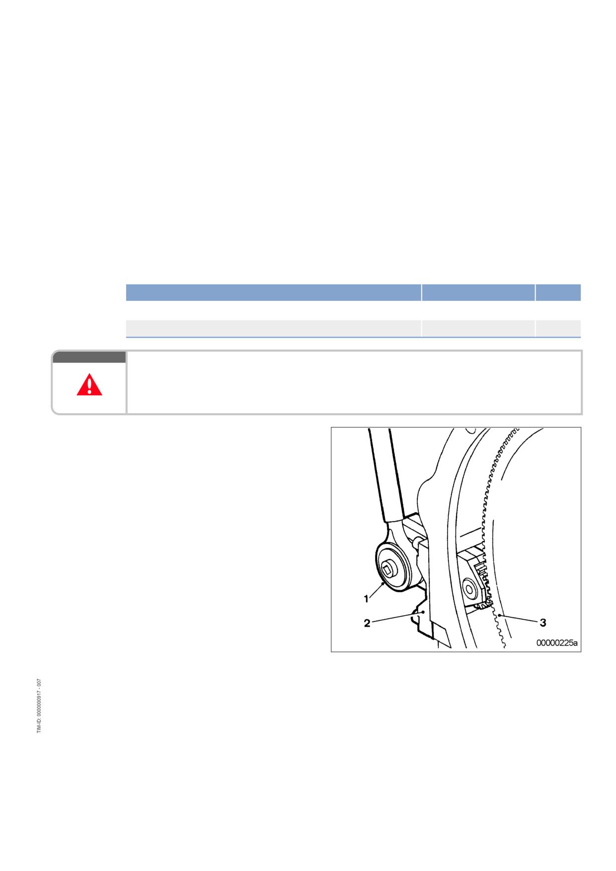
7 Task Description
7.1
Engine
7.1.1
Engine - Barring manually
Preconditions
☑ Engine is stopped and starting disabled.
Special tools, Material, Spare parts
Designation / Use
Part No.
Qty.
Barring device
F6555766
1
Ratchet with extension
F30006212
1
DANGER
Unguarded rotating and moving engine components.
Risk of serious injury - Danger to life!
• Before barring the engine, ensure that nobody is in the danger zone.
Engine - Barring manually
1.
Remove guard plate.
2.
Engage barring device (2) with ring gear (3)
and install on flywheel housing.
3.
Place ratchet (1) onto barring device (2).
4.
Rotate crankshaft in engine direction of ro-
tation. Apart from the normal compression
resistance, there should be no further re-
sistance.
5.
For barring device removal, follow reverse
sequence of working steps.
MS150064/01E 2011-11 | Task Description | 63
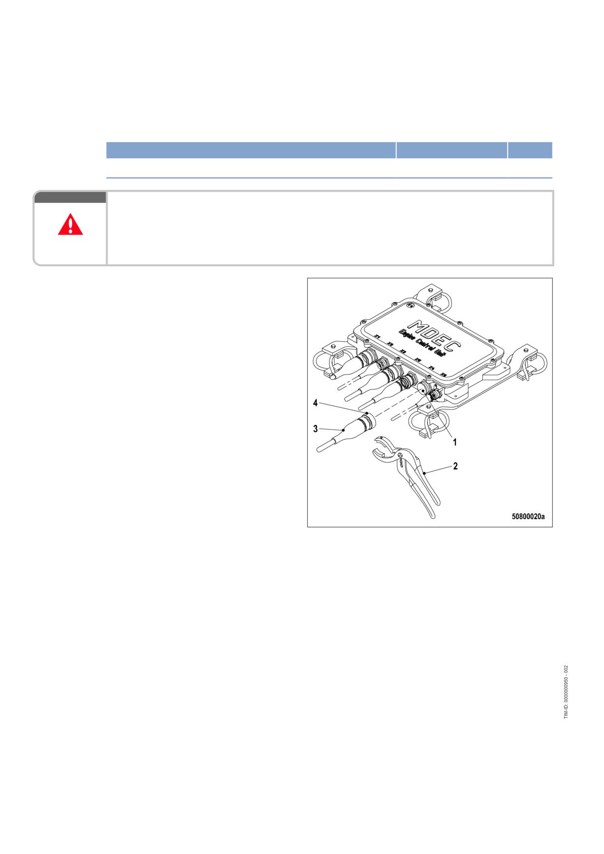
7.1.2
Engine - Barring with starting system
Special tools, Material, Spare parts
Designation / Use
Part No.
Qty.
Connector pliers
0135315483
1
DANGER
Unguarded rotating and moving engine components.
Risk of serious injury - danger to life!
• before barring or starting the engine, ensure that nobody is in the danger zone.
• After working on the engine, check that all protective devices have been reinstalled and all tools
removed from the engine.
Engine - Barring with starting
system
1.
Disengage the bayonet coupling (4) of con-
nector X4 with connector pliers (2) and
withdraw connector (3) from engine gover-
nor.
2.
Bar engine in unloaded condition: Press
START button.
3.
Let the crankshaft rotate until oil pressure is
indicated.
4.
Engine start is automatically interrupted
when specified starting period is expired. If
necessary, re-start the engine after approx.
20 seconds.
5.
Plug connector X4 (3) and use connector
pliers (2) to secure the bayonet coupling (4)
by turning it clockwise until it latches into
place.
64 | Task Description | MS150064/01E 2011-11
7.1.3
Engine - Test run
DANGER
Unguarded rotating and moving engine components.
Risk of serious injury - danger to life!
• Before barring or starting the engine, make sure that nobody is in the danger zone.
WARNING
Engine noise above 85 dB (A).
Risk of damage to hearing!
• Wear ear protectors.
Engine - Test run
1.
Start engine (→ Page 39).
2.
Perform test run not below 1/3 load and at least until steady-state temperature is reached.
3.
Carry out operational checks (→ Page 41).
4.
Stop engine (→ Page 42).
MS150064/01E 2011-11 | Task Description | 65
7.2
Cylinder Liner
7.2.1
Cylinder liner - Endoscopic examination
Preconditions
☑ Engine is stopped and starting disabled
Special tools, Material, Spare parts
Designation / Use
Part No.
Qty.
Rigid endoscope
Y20097353
1
Preparatory steps
1.
Remove cylinder head cover (→ Page 75).
2.
Remove injector (→ Page 78).
Positioning crankshaft at BDC
1.
Using barring device, turn crankshaft until crankshaft journal of the cylinder to be tested has reached
BDC.
2.
Insert endoscope into cylinder liner through injector seat.
Endoscopic examination of cylinder liner
Findings
Measure
• Thin carbon coating on circumference of carbon scraper ring
No action required
• Slight localized additive deposits at top edge
• Localized smooth areas at bottom edge
• Carbon deposits on circumference in clearance between top piston
ring and bottom edge of carbon scraper ring
• First signs of marks left by top piston ring
• Bright mark on entire circumference
• Consistent honing pattern without objections
• First signs of marks left by lower cooling bores
• Running pattern seems darker
• Dark areas with even or varying degrees of discoloration
Further endoscopic examina-
• Beginning and end of the discoloration are not sharply defined and
tion required as part of main-
do not cover the entire stroke area
tenance work
• Dark areas in the upper section of the cooling bore, remaining cir-
cumference without objections
• Piston rings without objections
• On the entire circumference, apart from light areas of discoloration
Cylinder liner must be re-
(that do not impair operation) clearly darker stripes that start at the
placed; Service must be con-
top piston ring
tacted
• Heat discoloration in the direction of stroke and honing pattern dam-
age
• Heat discoloration of piston rings
1.
Compile endoscopic report using the table.
2.
Use technical terms for description of the liner surface (→ Page 68).
3.
Depending on findings:
• Do not take any action or
• carry out a further endoscopic examination as part of maintenance work or
• contact Service; cylinder liner must be replaced.
66 | Task Description | MS150064/01E 2011-11
Final steps
1.
Install injector (→ Page 78).
2.
Install cylinder head cover (→ Page 75).
MS150064/01E 2011-11 | Task Description | 67
7.2.2
Cylinder liner - Instructions and comments on endoscopic and visual
examination
Terms used for endoscopic examination
Use the terms listed below to describe the condition of the cylinder-liner surface in the endoscopic exami-
nation report.
Findings
Measure
Minor dirt scores
Minor dirt scores can occur during the assembly of a new engine (honing prod-
ucts, particles, broken-off burrs). Removed cylinders clearly show such scoring
on the running surface under endoscope magnification. Cannot be felt with the
fingernail.
Findings not critical.
Single scores
Clearly visible scores caused by hard particles. They usually start in the TDC
area and cross through the hone pattern in the direction of stroke.
Findings not critical.
Scored area
These areas consist of scores of different length and depth next to one anoth-
er. In most cases, they are found at the 6-o'clock and 12-o'clock positions (in-
let/exhaust) along the transverse engine axis.
Findings not critical.
Smoothened area
Smoothened areas are on the running surface but almost the whole honing
pattern is still visible. Smoothened areas appear brighter and more brilliant
than the surrounding running surface.
Findings not critical.
Bright area
Bright areas are on the running surface and show local removal of the honing
pattern. Grooves from honing process are not visible any more.
Discoloration
This is caused by oxidation (surface discoloration through oil or fuel) and tem-
perature differences around the liner. It appears rather darker within the honed
structure in contrast to the bright metallic running surface. The honing pattern
is undisturbed. Discolorations extend in stroke direction and may be interrupt-
ed.
Findings not critical.
Corrosion fields / spots
Corrosion fields / spots result from water (condensed water) with the valves in
the overlap (open) position. They are clearly visible due to the dark color of the
honing groove bottom.
This corrosion is not critical unless there is corrosion pitting.
Black lines
Black lines are a step towards heat discoloration. They are visible as a clear
discoloration from TDC to BDC in the running surface and the start of localized
damage to the honing pattern.
Cylinder liners with a large number of black lines around the running surface
have limited service life and should be replaced.
68 | Task Description | MS150064/01E 2011-11
Findings
Measure
Burn mark
This is caused by a malfunction in the liner / ring tribosystem. Usually they run
over the whole ring-travel area (TDC/BDC), starting at the first TDC-ring and
becoming more visible from the second TDC-ring 2 onwards and less pro-
nounced from TDC-ring 1. The honing pattern is usually no longer visible and
displays a clearly defined (straight) edge to the undisturbed surface. The dam-
aged surface is usually discolored. The circumferential length varies.
Liners with burn marks, or heat discoloration, starting in TDC ring 1 have to be
replaced.
Seizure marks, scuff-
Irregular circumference lengths and depths. Can be caused either by the pis-
ing
ton skirt or the piston crown. Material deposits on the liner (smear), heavy dis-
coloration. Severe, visible scoring.
Replace liner.
Evaluation of findings and further measures
The findings in the start phase of oxidation discoloration and heat discoloration are similar. A thorough
investigation and compliance with the above evaluation criteria allow an unambiguous evaluation. To
avoid unnecessary disassembly work, it is recommended that another inspection be carried out after fur-
ther operation of the engine.
MS150064/01E 2011-11 | Task Description | 69
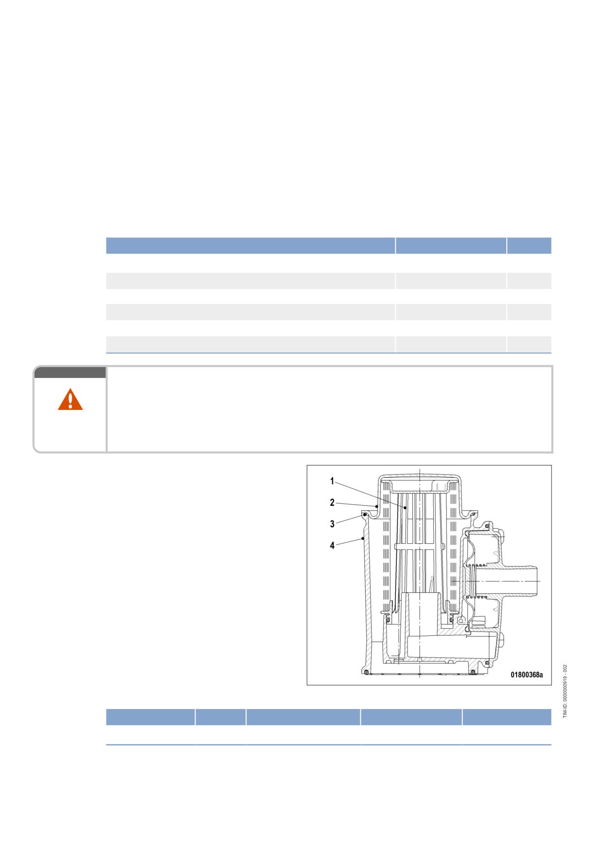
7.3
Crankcase Breather
7.3.1
Crankcase breather - Oil separator replacement, diaphragm check and
replacement
Preconditions
☑ Engine is stopped and starting disabled.
Special tools, Material, Spare parts
Designation / Use
Part No.
Qty.
Torque wrench, 6-50 Nm
F30027336
1
Ratchet adapter
F30027340
1
Engine oil
Filter element
(→ Spare Parts Catalog)
Diaphragm
(→ Spare Parts Catalog)
Seal
(→ Spare Parts Catalog)
WARNING
Hot oil.
Oil can contain combustion residues which are harmful to health.
Risk of injury and poisoning!
• Wear protective clothing, gloves, and goggles / safety mask.
• Avoid contact with skin.
• Do not inhale oil vapor.
Replacing oil separator
1.
Remove cover (2) with O-ring (3).
2.
Remove filter element (1) from housing (4).
3.
Insert new filter element in housing (4).
4.
Fit cover (2) with new O-ring.
5.
Use torque wrench to tighten the screws of cover (2) to the specified torque.
Name
Size
Type
Lubricant
Value/Standard
Screw
Tightening torque
(Engine oil)
6 Nm +2 Nm
6.
Replace further oil separator elements in the same way.
70 | Task Description | MS150064/01E 2011-11
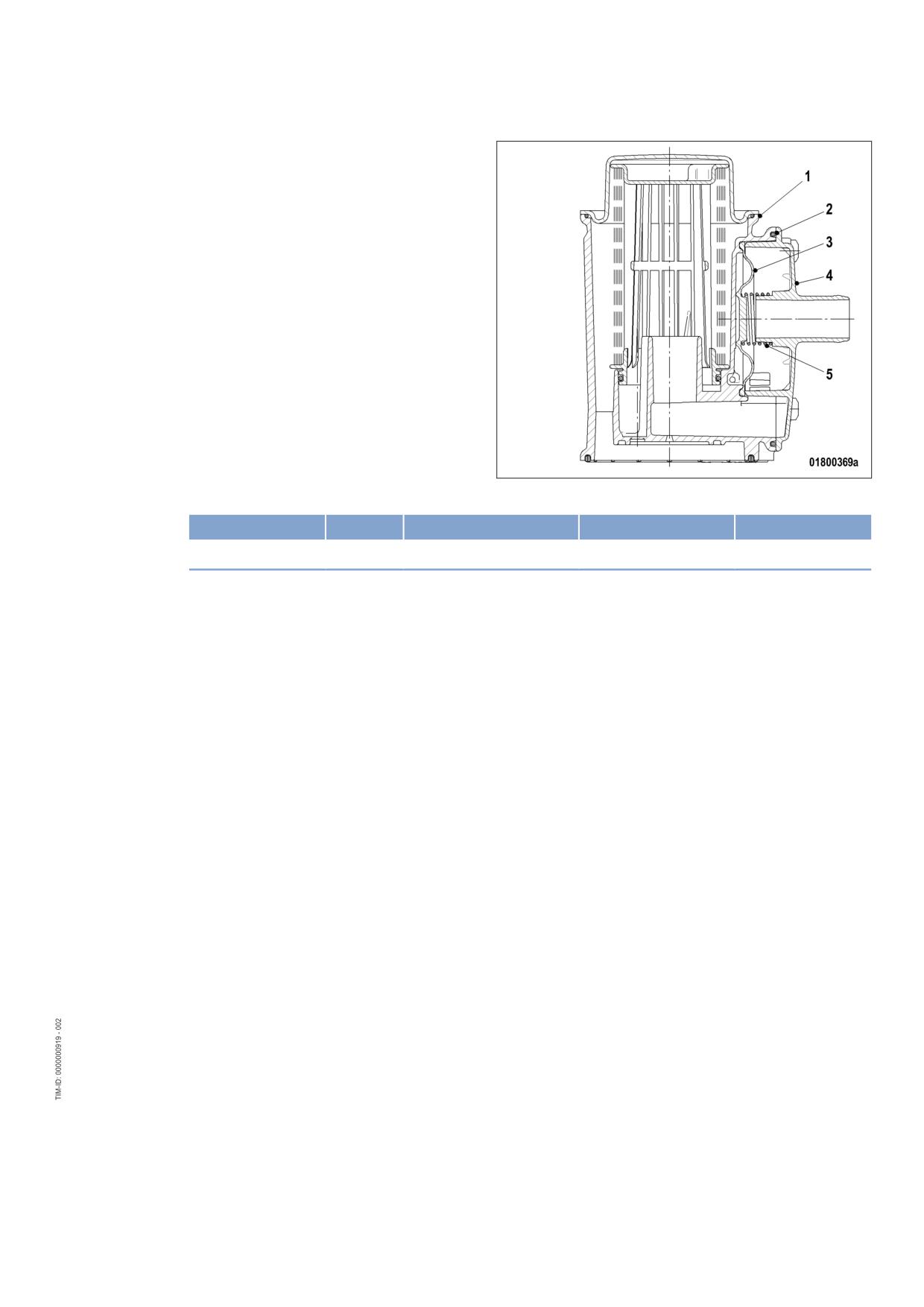
Checking diaphragm
1.
Remove cover (4).
2.
Remove spring (5), seal (2) and diaphragm
(3).
3.
Check diaphragm (3) for damage, fit new
diaphragm if used one is damaged.
4.
Install diaphragm (3) on housing (1).
5.
Install new seal (2) and spring (5) together
with cover (4).
6.
Use torque wrench to tighten the screws of cover (4) to the specified torque.
Name
Size
Type
Lubricant
Value/Standard
Screw
Tightening torque
(Engine oil)
6 Nm +2 Nm
7.
Check diaphragms in further oil separators in the same way.
MS150064/01E 2011-11 | Task Description | 71
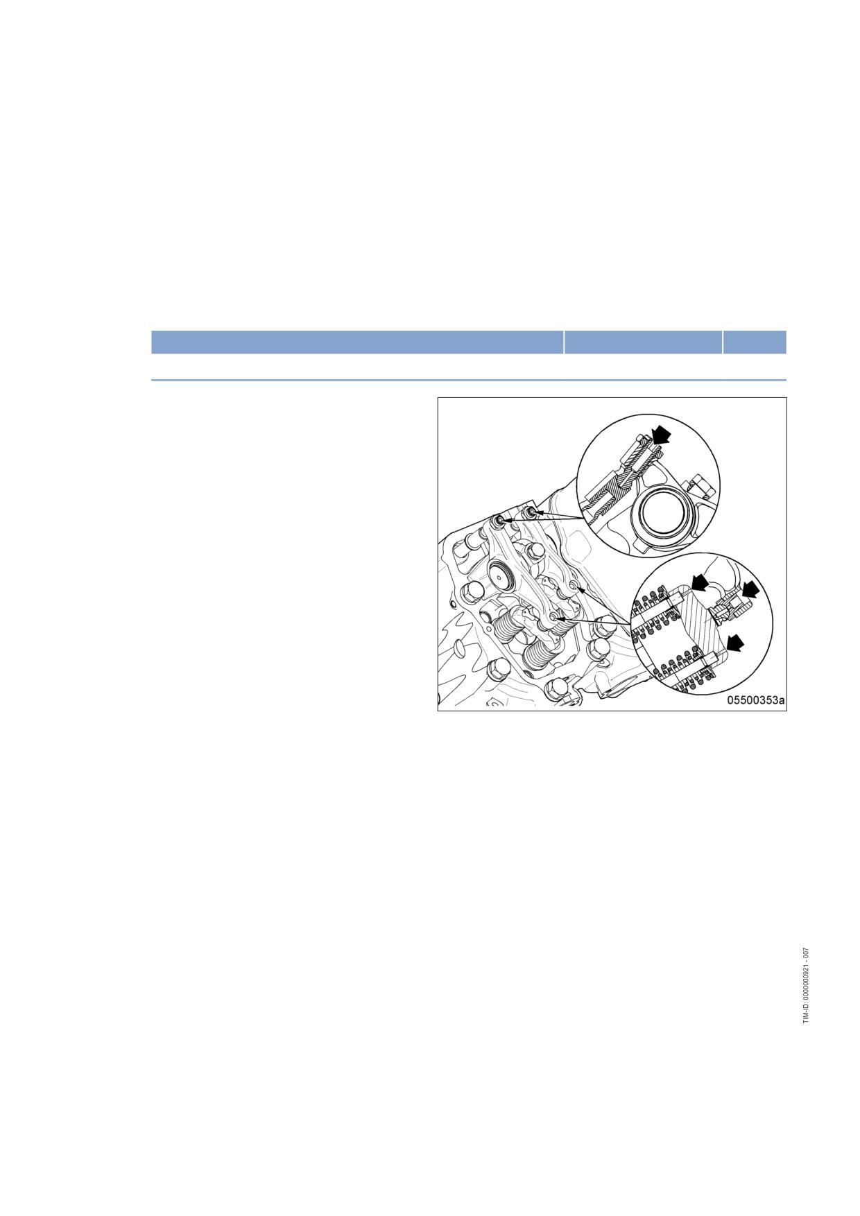
7.4
Valve Drive
7.4.1
Valve gear - Lubrication
Preconditions
☑ Engine is stopped and starting disabled.
Special tools, Material, Spare parts
Designation / Use
Part No.
Qty.
Engine oil
Valve gear - Lubrication
1.
Remove cylinder head covers (→ Page 75).
2.
Fill oil chambers of valve bridges with oil.
3.
Fill oil chambers of rocker arms and adjust-
ing screws with oil.
4.
Install cylinder head covers (→ Page 75).
72 | Task Description | MS150064/01E 2011-11
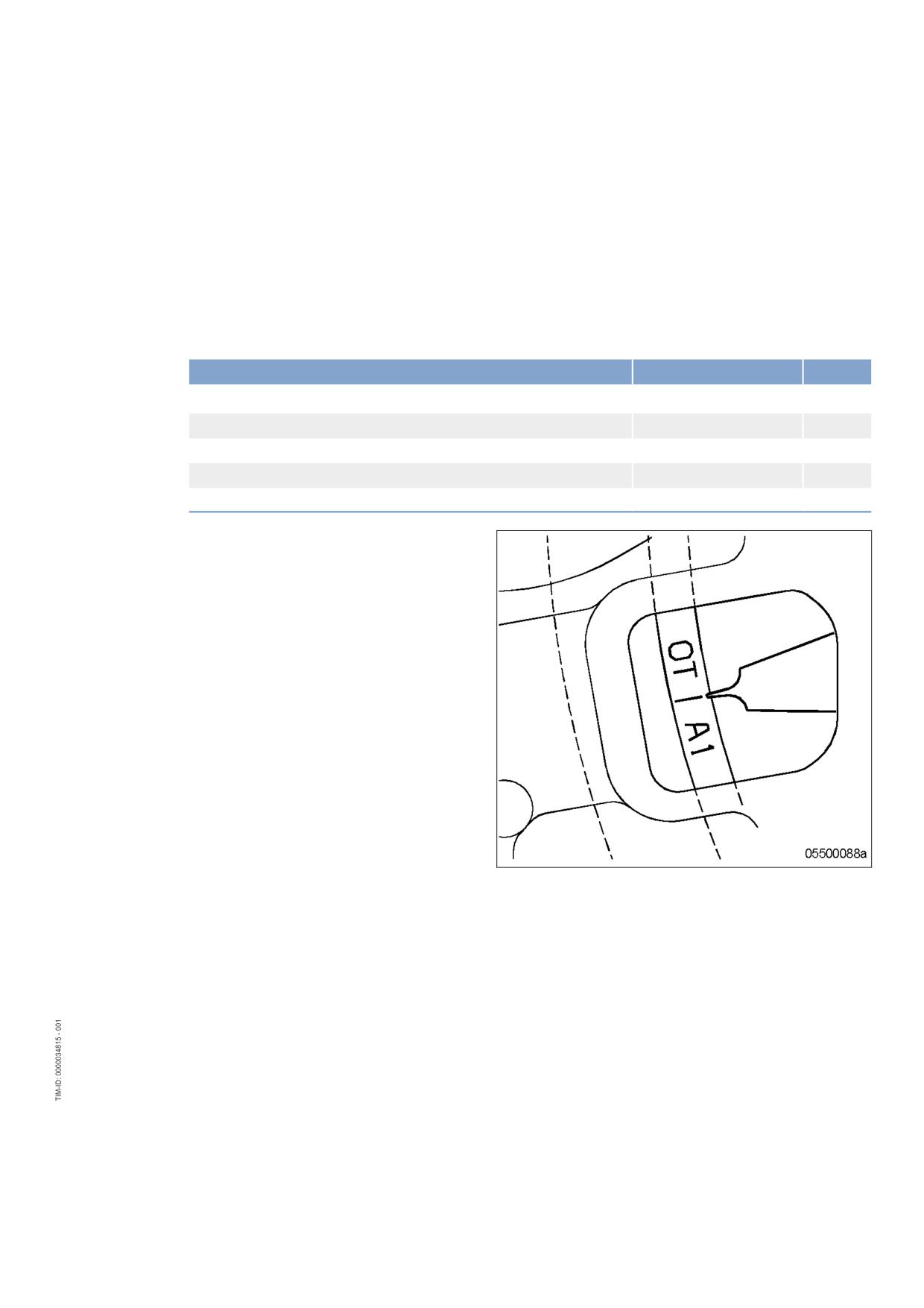
7.4.2
Valve clearance - Check and adjustment
Preconditions
☑ Engine is stopped and starting disabled.
☑ Engine coolant temperature is max. 40 °C.
☑ Valves are closed.
Special tools, Material, Spare parts
Designation / Use
Part No.
Qty.
Feeler gauge
Y20010128
1
Torque wrench, 60-320 Nm
F30047446
1
Allen key
F30002817
1
Socket wrench, 24 mm
F30039526
1
Engine oil
Preparatory steps
1.
Remove cylinder head cover (→ Page 75).
2.
Install barring tool (→ Page 63).
3.
Rotate crankshaft with barring tool in en-
gine direction of rotation until marking "OT-
A1" and pointer are aligned.
MS150064/01E 2011-11 | Task Description | 73
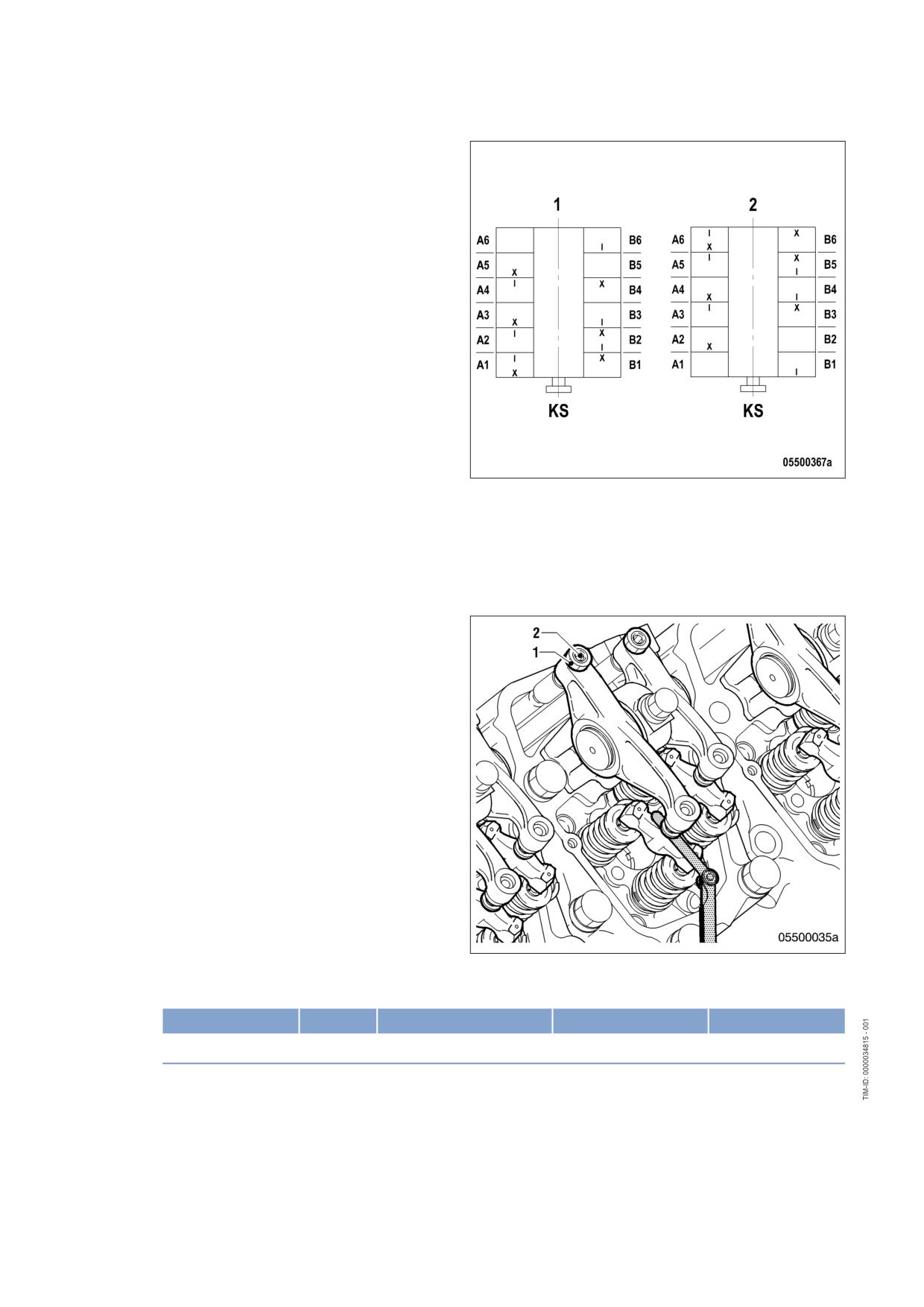
Checking valve clearance at two
crankshaft positions
1.
Check TDC position of piston in cylinder
A1:
• If the rocker arms are unloaded on cylin-
der A1, the piston is in firing TDC.
• If the rocker arms are under load on cyl-
inder A1, the piston is in overlap TDC.
2.
Check valve clearance with cold engine:
• Inlet valves (long rocker arm) = 0.2 mm
• Exhaust valves (short rocker arm) =
0.5 mm
3.
Check all valve clearances in two crank-
shaft positions (firing TDC and overlap TDC
of cylinder A1) as per diagram.
1 Cylinder A1 is in firing TDC
2 Cylinder A1 is in overlap TDC
I Inlet valve
X Exhaust valve
4.
Use feeler gauge to determine the distance
between valve bridge and rocker arm.
5.
If the deviation from the set value exceeds
0.1 mm, adjust valve clearance.
Adjusting valve clearance
1.
Release locknut (1).
2.
Insert feeler gauge between valve bridge
and rocker arm.
3.
Using Allen key, set adjusting screw (2) so
that the specified valve clearance is provid-
ed.
4.
Feeler gauge must just pass through the
gap.
5.
Tighten locknut (1) with torque wrench to the specified tightening torque, holding the adjusting screw (2)
to prevent it from turning.
Name
Size
Type
Lubricant
Value/Standard
Locknut
M16 x 1.5
Tightening torque
(Engine oil)
90 Nm +9 Nm
6.
Replace or rectify adjusting screws and/or locknuts which do not move freely.
7.
Check valve clearance.
Final steps
1.
Remove barring tool (→ Page 63).
2.
Install cylinder head cover (→ Page 75).
74 | Task Description | MS150064/01E 2011-11
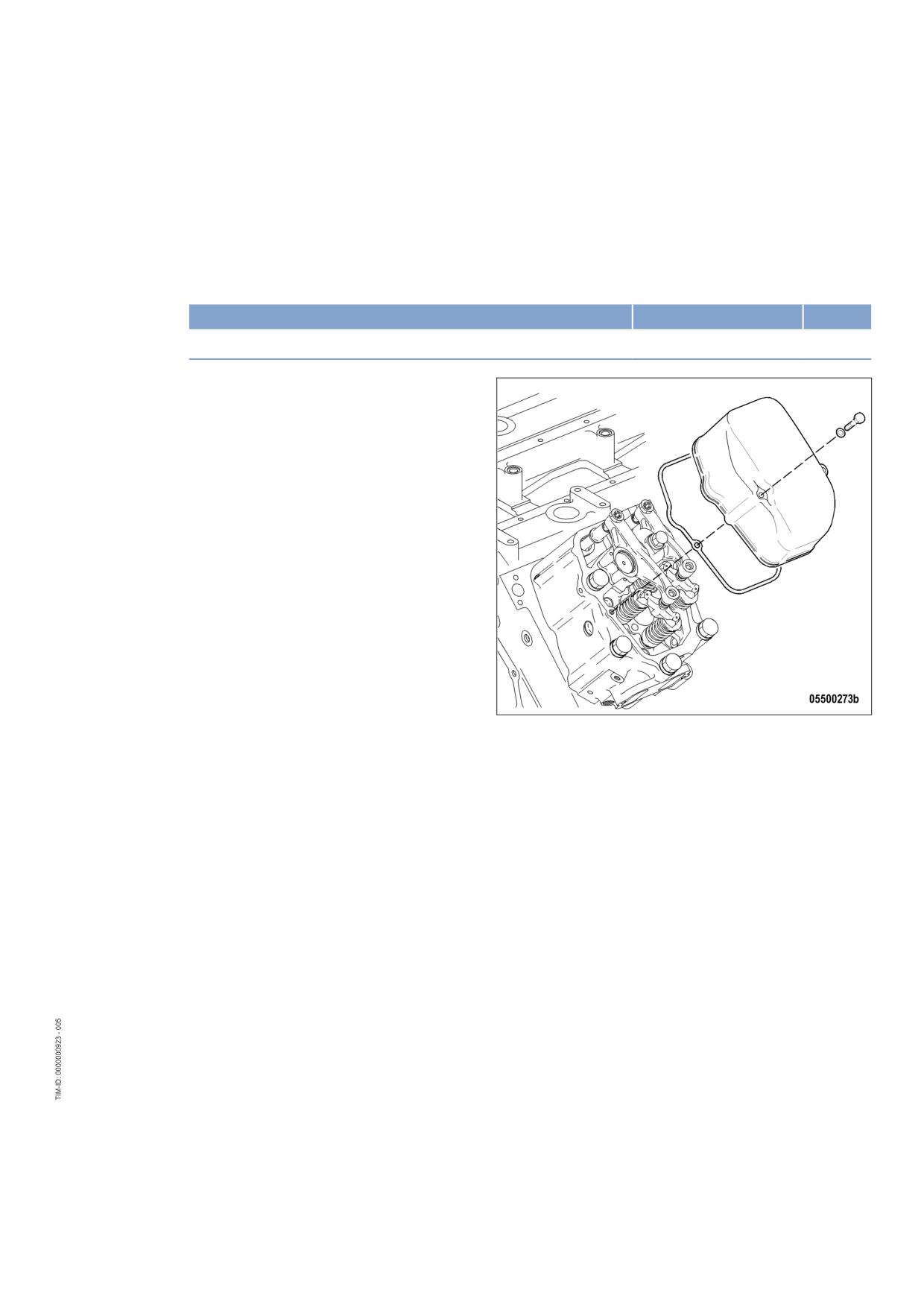
7.4.3
Cylinder head cover - Removal and installation
Preconditions
☑ Engine shut down and starting disabled.
Special tools, Material, Spare parts
Designation / Use
Part No.
Qty.
Gasket
(→ Spare Parts Catalog)
Removing cylinder head cover
1.
Clean cylinder head covers prior to removal
if they are heavily soiled.
2.
Remove screws.
3.
Remove cylinder head cover with gasket
from cylinder head.
Installing cylinder head cover
1.
Clean mating face.
2.
Check condition of gasket, replace if necessary.
3.
Place gasket and cylinder head cover on cylinder head.
4.
Install cylinder head cover.
MS150064/01E 2011-11 | Task Description | 75
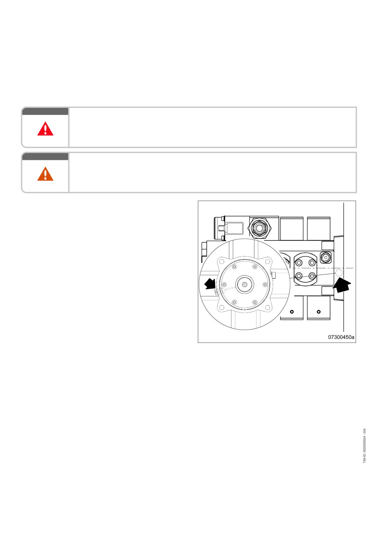
7.5
Injection Pump / HP Pump
7.5.1
HP pump - Relief bore check
DANGER
Unguarded rotating and moving engine components.
Risk of serious injury - danger to life!
• Take special care when working on a running engine.
WARNING
Engine noise above 85 dB (A).
Risk of damage to hearing!
• Wear ear protectors.
Checking HP pump relief bore
1.
Check relief bore for oil and fuel discharge
by visual inspection.
2.
If relief bore is contaminated, stop the en-
gine, disable engine start, and clean relief
bore.
3.
Note the following in case of fluid dis-
charge:
• Heavy discharge means continuous dis-
charge of fluids (leakage). Contact Serv-
ice.
• Minor discharge of fluids up to 10 drops
per day is normal (moistening) and not
considered a leakage.
76 | Task Description | MS150064/01E 2011-11
7.6
Injection Valve / Injector
7.6.1
Injector - Replacement
Special tools, Material, Spare parts
Designation / Use
Part No.
Qty.
Injector
(→ Spare Parts Catalog)
Replacing injector
u Remove injector and install new injector (→ Page 78).
MS150064/01E 2011-11 | Task Description | 77
7.6.2
Injector - Removal and installation
Preconditions
☑ Engine shut down and starting disabled.
Special tools, Material, Spare parts
Designation / Use
Part No.
Qty.
Installation and removal tool for injector
F6790161
1
Milling cutter
F30452739
1
Slotted nut screwdriver
F30452578
1
Torque wrench, 0.5-5 Nm
0015384230
1
Torque wrench, 10-60 Nm
F30510423
1
Torque wrench, 60-320 Nm
F30047446
1
Assembly paste (Optimoly Paste White T)
40477
1
Grease (Kluthe Hakuform 30-10/emulsifier)
X00058060
1
Engine oil
WARNING
Fuels are combustible.
Risk of fire and explosion!
• Avoid open flames, electrical sparks and ignition sources.
• Do not smoke.
CAUTION
Removal of all injectors.
Damage to component!
• Ensure that the high-pressure fuel accumulator is secured on the engine through two HP lines.
CAUTION
Cable damage during operation.
Fire hazard!
• Twist cables when installing.
• Ensure that cables do not touch components.
Preparatory steps
1.
Shut off fuel inlet to engine.
2.
Remove cylinder head cover (→ Page 75).
78 | Task Description | MS150064/01E 2011-11
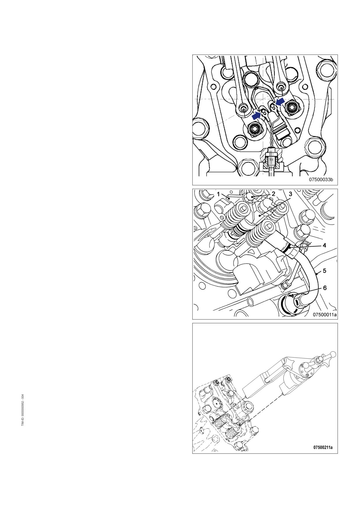
Removing injector
Note:
Always replace the first and last injectors of
one engine side first. Replace the inner in-
jectors only after the installation of the outer
injectors on this engine side is completed.
1.
Undo cable terminal screws (arrow) on in-
jector and remove cable terminals.
2.
Remove screw (2) and take off hold-down
clamp (1).
3.
Remove high-pressure fuel line (5).
4.
Install installation/removal device on cylin-
der head.
5.
Remove injector with installation/removal
device.
6.
Remove installation/removal device.
MS150064/01E 2011-11 | Task Description | 79
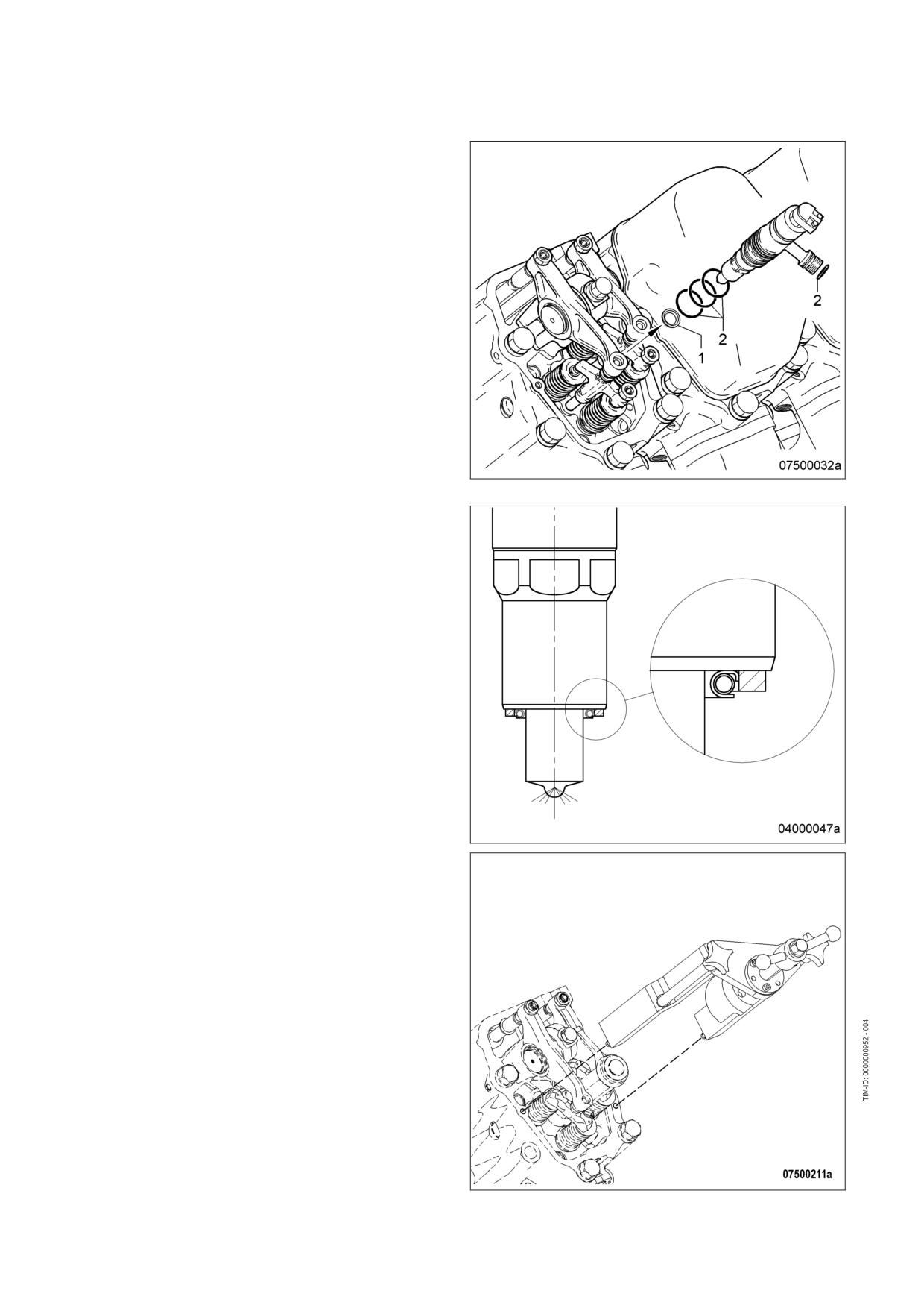
7.
Remove sealing ring (1) from injector or use
a self-made wire hook to extract it from the
cylinder head.
8.
Remove O-rings (2) from injector.
9.
Cover all connections and bores, or seal
with suitable plugs.
Installing injector
1.
Remove all plugs before installing.
2.
Coat nozzle retaining nut area of injector
with assembly paste.
3.
Fit new O-rings on injector and coat with
grease.
4.
Fit new sealing ring on injector with grease
ensuring correct installation position of seal-
ing ring.
5.
Clean sealing surface on cylinder head and
protective sleeve with milling cutter.
6.
Insert injector into cylinder head ensuring
that the HP line connection is aligned cor-
rectly.
7.
Press in injector with installation/removal
device.
8.
Remove installation/removal device.
80 | Task Description | MS150064/01E 2011-11
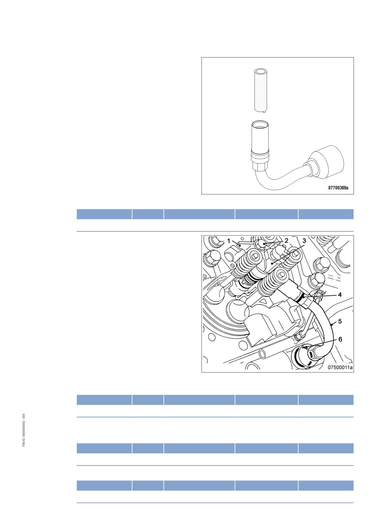
9.
Use slotted screwdriver to check thrust ring
at both line ends for secure seating.
10.
Tighten loose thrust ring to the specified tightening torque.
Name
Size
Type
Lubricant
Value/Standard
Thrust ring
Tightening torque
5 Nm to 10 Nm
11.
Coat screw head mating face (2) and
thread with engine oil.
12.
Place hold-down clamp (1) in correct installation position. Tighten screw (2) with torque wrench to the
specified initial tightening torque.
Name
Size
Type
Lubricant
Value/Standard
Screw
M12
Preload torque
(Engine oil)
5 Nm to 10 Nm
13.
Fit O-rings (4) and (6) on high-pressure fuel line (5) and coat with grease.
14.
Tighten high-pressure fuel line (5) to the specified initial tightening torque.
Name
Size
Type
Lubricant
Value/Standard
HP line
Preload torque
(Engine oil)
5 Nm to 10 Nm
15.
Tighten screw (2) to specified torque using a torque wrench.
Name
Size
Type
Lubricant
Value/Standard
Screw
M12
Tightening torque
100 Nm + 10 Nm
MS150064/01E 2011-11 | Task Description | 81
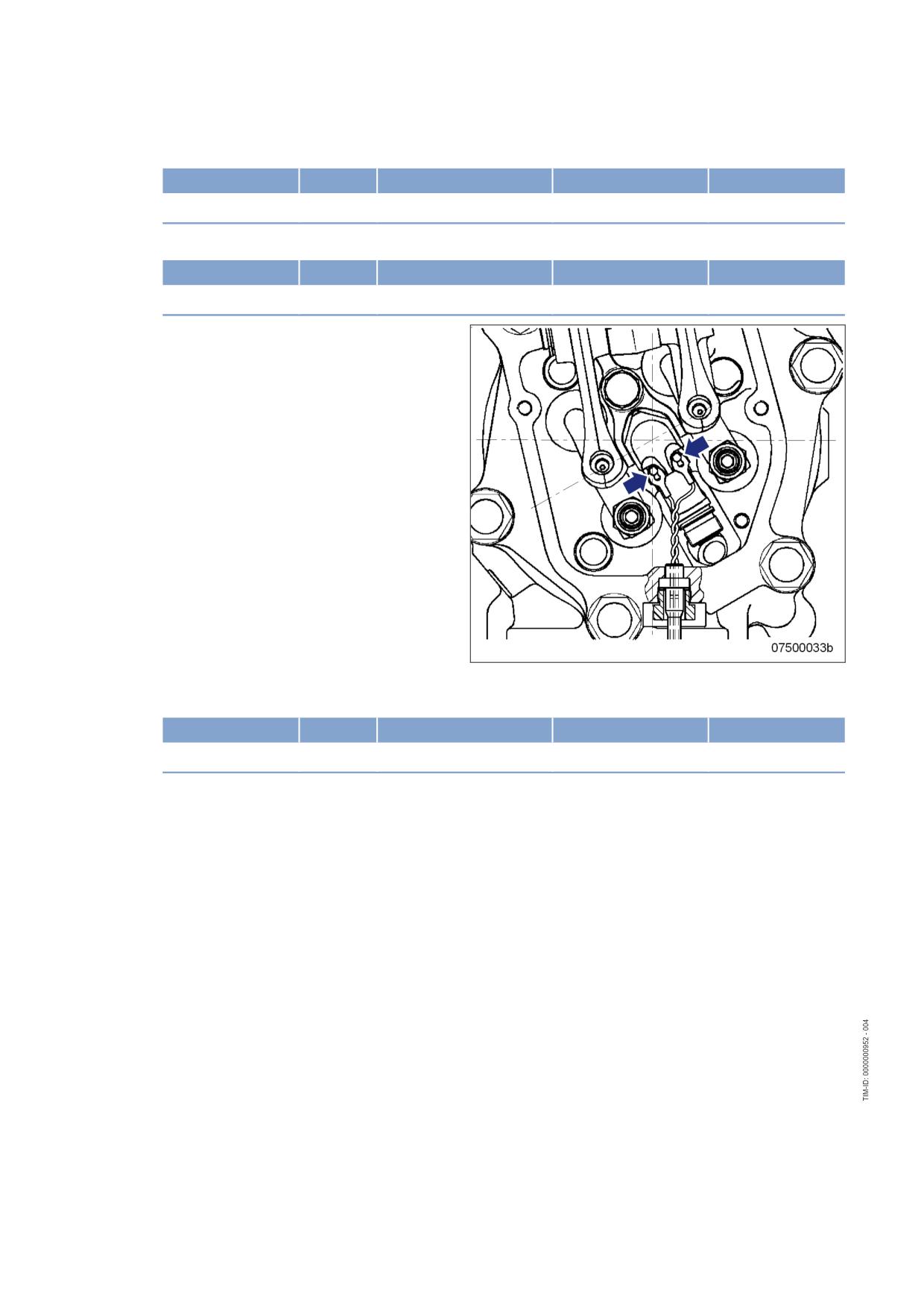
16.
Tighten union nut of connecting piece (limiting valve) to specified torque using a torque wrench.
Name
Size
Type
Lubricant
Value/Standard
Union nut
Tightening torque
140 Nm + 10 Nm
17.
Tighten union nut of connecting piece (injector) to specified torque using a torque wrench.
Name
Size
Type
Lubricant
Value/Standard
Union nut
Tightening torque
120 Nm +10 Nm
18.
Twist cable several times.
19.
Insert cable terminals (arrows) underneath screws on injector and tighten screws to specified torque us-
ing a torque wrench.
Name
Size
Type
Lubricant
Value/Standard
Screw
Tightening torque
1.5 Nm
Final steps
1.
Install cylinder head cover (→ Page 75).
2.
Open up fuel inlet to engine.
82 | Task Description | MS150064/01E 2011-11
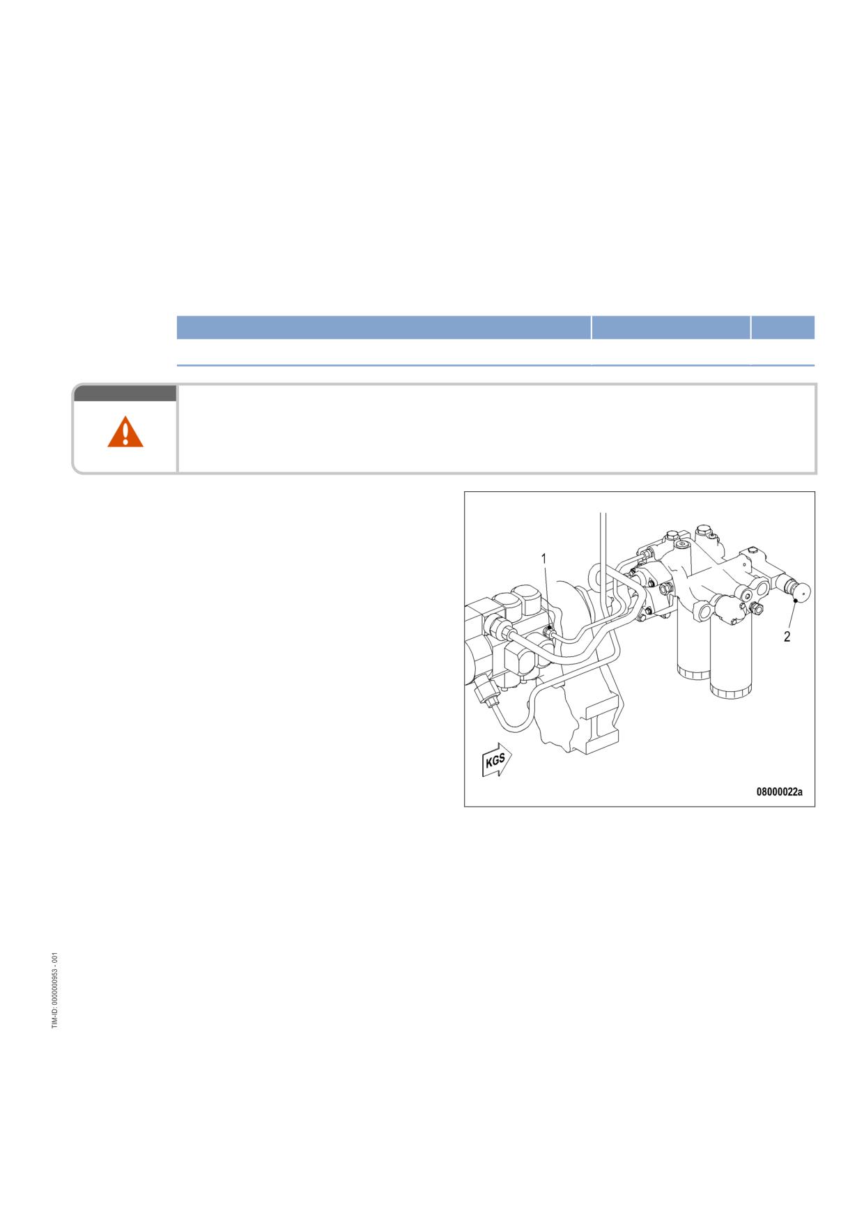
7.7
Fuel System
7.7.1
Fuel system - Venting
Preconditions
☑ Engine is stopped and starting disabled.
Special tools, Material, Spare parts
Designation / Use
Part No.
Qty.
Diesel fuel
WARNING
Fuels are combustible.
Risk of fire and explosion!
• Avoid open flames, electrical sparks and ignition sources.
• Do not smoke.
Venting LP fuel system
1.
Loosen flushing/return line of HP pump at
connection (1).
2.
Unlock fuel priming pump (2), screw out
handle.
3.
Operate the fuel priming pump (2) with the
handle until bubble-free fuel comes out of
the connection (1).
4.
Lock fuel priming pump (2), screw in han-
dle.
5.
Verify that fuel priming pump (2) is locked:
Handle must be tightened.
6.
Tighten connection (1) of flushing/return
line.
MS150064/01E 2011-11 | Task Description | 83
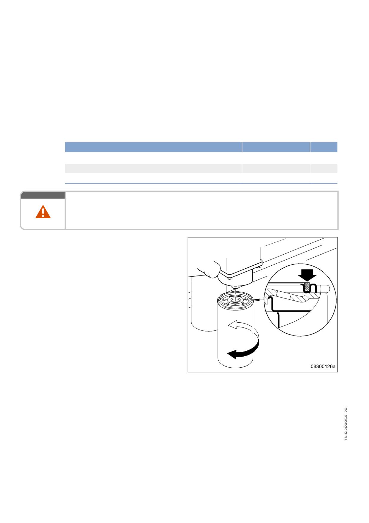
7.8
Fuel Filter
7.8.1
Fuel filter - Replacement
Preconditions
☑ Engine is stopped and starting disabled.
Special tools, Material, Spare parts
Designation / Use
Part No.
Qty.
Filter wrench
F30379104
1
Engine oil
Easy-change filter
(→ Spare Parts Catalog)
WARNING
Fuels are combustible.
Risk of fire and explosion!
• Avoid open flames, electrical sparks and ignition sources.
• Do not smoke.
Replacing fuel filter
1.
Remove easy-change filter using filter
wrench.
2.
Clean sealing surface on filter head.
3.
Slightly lubricate seal on the easy-change
filter.
4.
Screw on easy-change filter by hand until
the seal connects and tighten manually.
5.
Vent fuel system (→ Page 83).
6.
Replace other easy-change filters in the
same way.
84 | Task Description | MS150064/01E 2011-11
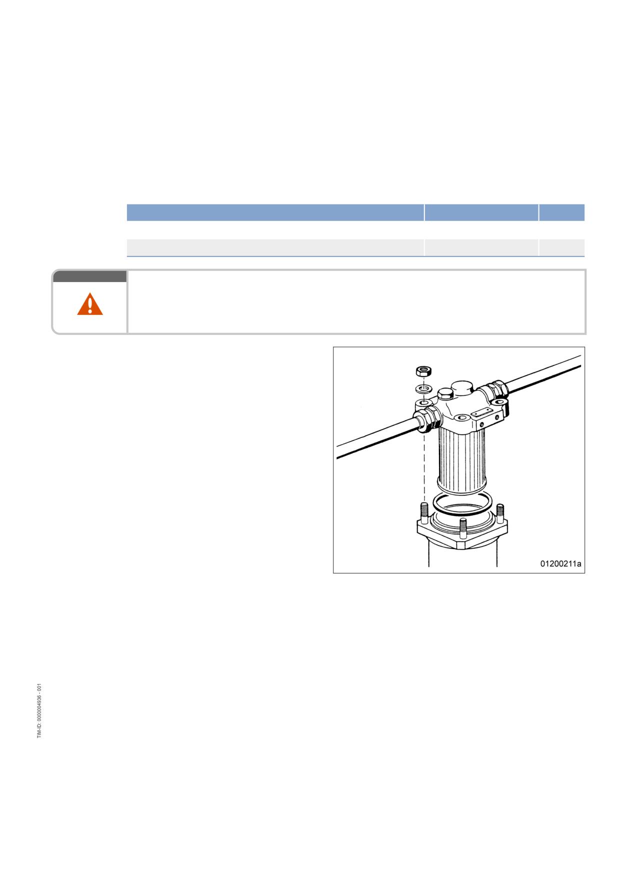
7.8.2
Fuel prefilter cleaning
Preconditions
☑ Engine is stopped and starting disabled.
Special tools, Material, Spare parts
Designation / Use
Part No.
Qty.
Diesel fuel
Sealing ring
(→ Spare Parts Catalog)
WARNING
Fuels are combustible.
Risk of fire and explosion!
• Avoid open flames, electrical sparks and ignition sources.
• Do not smoke.
Fuel prefilter cleaning
1.
Shut off fuel supply.
2.
Remove nuts from filter head.
3.
Take off filter housing and drain fuel into
appropriate container.
4.
Remove filter-element securing nut and re-
move filter element by pulling it downwards.
5.
Wash filter element in clean fuel using a
smooth brush.
6.
Wash filter housing with clean fuel.
7.
Insert filter element into filter housing and
secure with nut.
8.
Place new sealing ring into groove in filter
head.
9.
Fit cover with seal and secure it with nuts
crosswise.
10.
Open fuel supply.
MS150064/01E 2011-11 | Task Description | 85
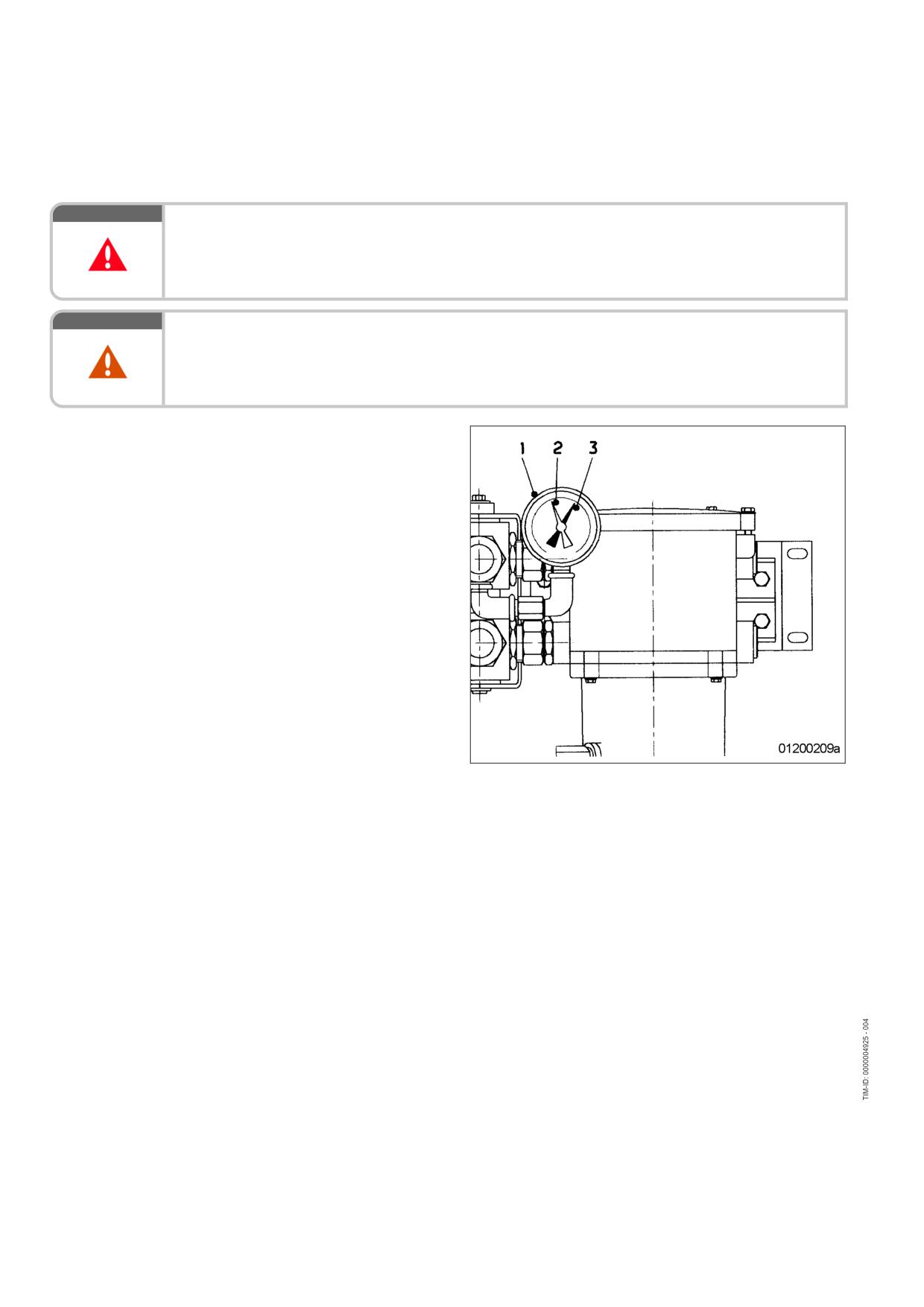
7.8.3
Fuel prefilter - Differential pressure gauge check and adjustment
DANGER
Unguarded rotating and moving engine components.
Risk of serious injury - danger to life!
• Take special care when working on a running engine.
WARNING
Engine noise above 85 dB (A).
Risk of damage to hearing!
• Wear ear protectors.
Adjusting differential pressure
gauge
1.
When installing the new filter element: align
adjustable pointer (2) with pressure-indicat-
ing pointer (3) of pressure gauge (1).
2.
Check differential pressure.
Checking differential pressure of fuel prefilter
1.
With the engine running at full load or rated power, read off pressure at gauge (1).
2.
If differential pressure as indicated between position of adjustable pointer (2) and pressure-indicating
pointer (3) of pressure gauge is ≥ 0.3 bar, flush filter element of the cut-in filter (→ Page 88).
86 | Task Description | MS150064/01E 2011-11
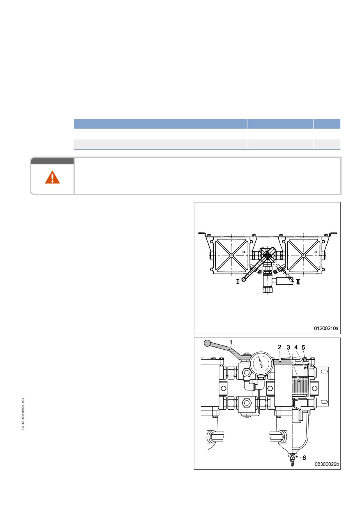
7.8.4
Fuel prefilter - Draining
Preconditions
☑ Engine is stopped and starting disabled.
Special tools, Material, Spare parts
Designation / Use
Part No.
Qty.
Diesel fuel
Gasket
(→ Spare Parts Catalog)
WARNING
Fuels are combustible.
Risk of fire and explosion!
• Avoid open flames, electrical sparks and ignition sources.
• Do not smoke.
Fuel prefilter - Draining
1.
Cut out filter to be drained.
I Left filter cut in
II Right filter cut in
2.
Open threaded vent plug (5) of filter to be
drained.
3.
Unlock drain valve (6) by pressing toggle
and open it.
4.
Drain water and contaminants from filter un-
til pure fuel emerges.
5.
Close drain valve (6).
6.
Remove screws for cover and take off cov-
er (2).
7.
Fill filter housing with clean fuel.
8.
Place new gasket in cover (2).
9.
Fit cover with gasket and secure it with
screws.
10.
Cut in the cut-out filter again.
11.
Close threaded vent plug (5) when fuel
emerges.
MS150064/01E 2011-11 | Task Description | 87
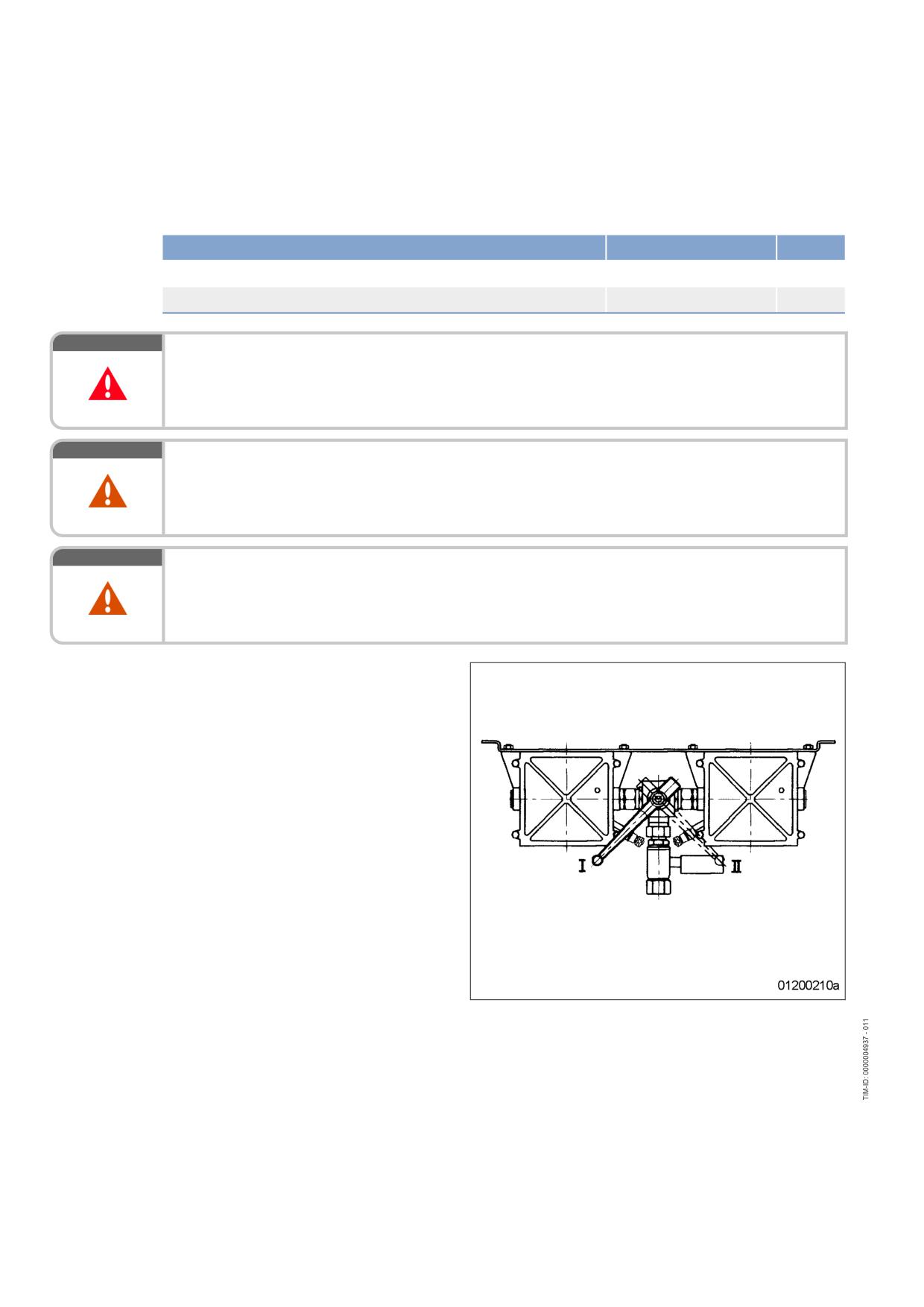
7.8.5
Fuel prefilter - Flushing
Special tools, Material, Spare parts
Designation / Use
Part No.
Qty.
Diesel fuel
Gasket
(→ Spare Parts Catalog)
DANGER
Unguarded rotating and moving engine components.
Risk of serious injury - danger to life!
• Take special care when working on a running engine.
WARNING
Fuels are combustible.
Risk of fire and explosion!
• Avoid open flames, electrical sparks and ignition sources.
• Do not smoke.
WARNING
Engine noise above 85 dB (A).
Risk of damage to hearing!
• Wear ear protectors.
Fuel prefilter - Flushing
1.
Cut out clogged filter.
I Left filter cut in
II Right filter cut in
88 | Task Description | MS150064/01E 2011-11
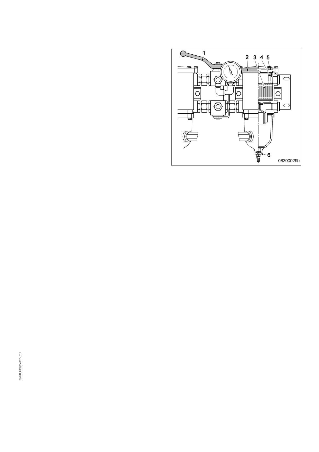
2.
Open threaded vent plug (5) of filter to be
flushed.
3.
Unlock drain valve (6) by pressing toggle,
open it and drain fuel.
Result:
Fuel flows from filtered side back to the un-
filtered side, flushing the filter deposits
downwards out of the filter.
4.
Close threaded vent plug (5) and drain
valve (6).
Fuel prefilter - Topping up with fuel
1.
Stop engine (→ Page 42) and disable engine start.
2.
Remove screws for cover and take off cover (2).
3.
Fill filter housing with clean fuel.
4.
Place new gasket in cover (2).
5.
Fit cover with gasket and secure it with screws.
6.
Check differential pressure (→ Page 86).
Result:
If flushing did not lead to an improvement of the differential pressure, replace filter element of fuel prefil-
ter (→ Page 90).
MS150064/01E 2011-11 | Task Description | 89
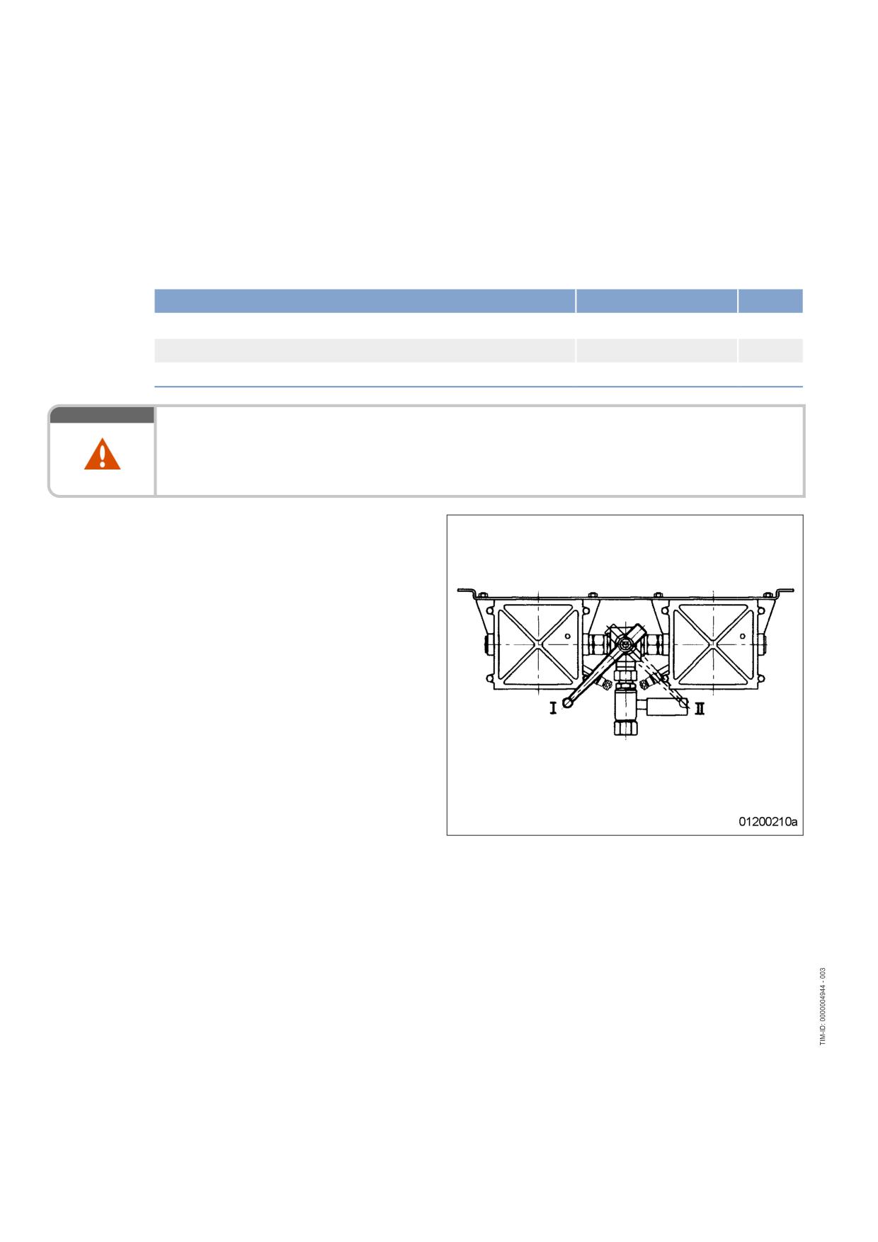
7.8.6
Fuel prefilter - Filter element replacement
Preconditions
☑ Engine is stopped and starting disabled.
Special tools, Material, Spare parts
Designation / Use
Part No.
Qty.
Diesel fuel
Filter element
(→ Spare Parts Catalog)
Gasket
(→ Spare Parts Catalog)
WARNING
Fuels are combustible.
Risk of fire and explosion!
• Avoid open flames, electrical sparks and ignition sources.
• Do not smoke.
Replacing filter element
1.
Cut out filter to be drained.
I Left filter cut in
II Right filter cut in
90 | Task Description | MS150064/01E 2011-11
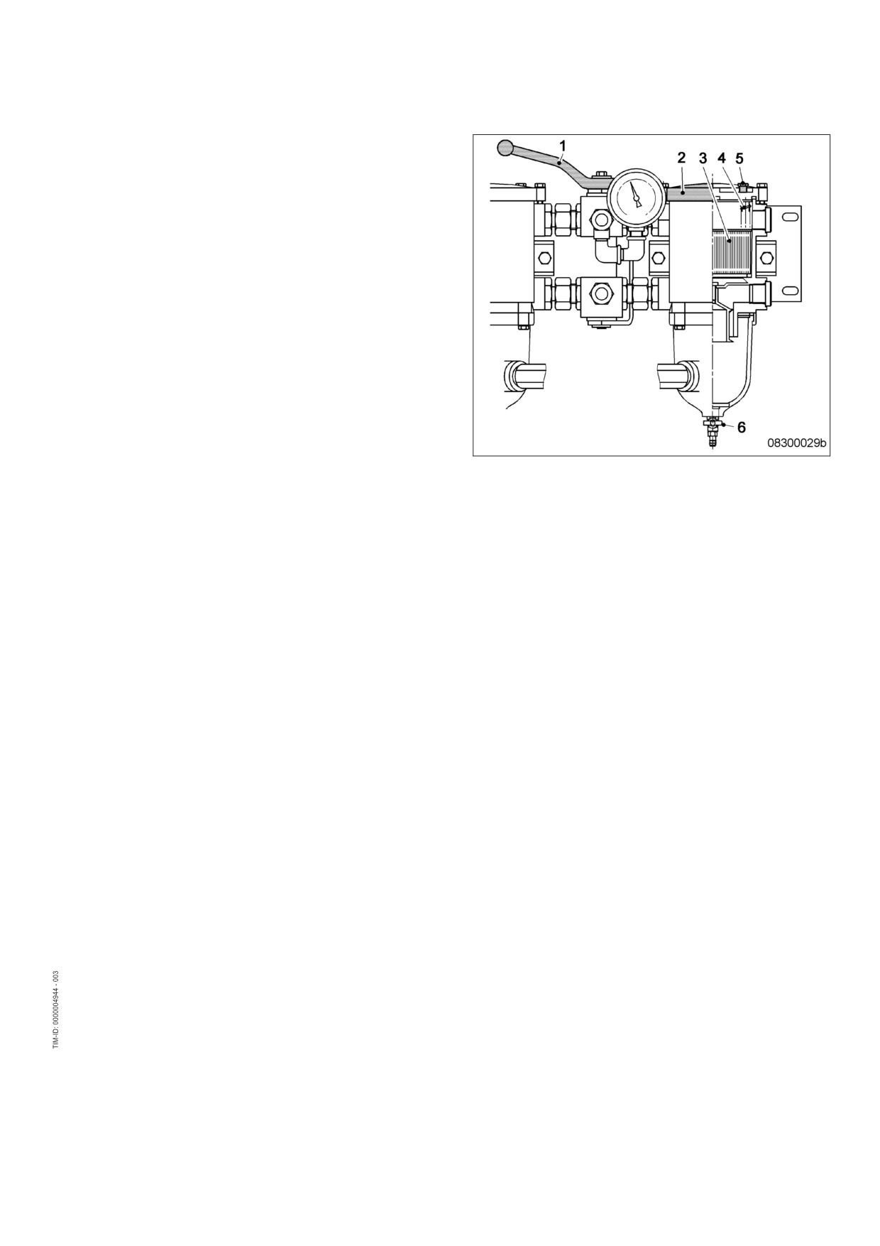
2.
Open threaded vent plug (5) of contaminat-
ed filter.
3.
Unlock drain valve (6) by pressing toggle
and open it.
4.
Drain water and dirt from filter.
5.
Close drain valve (6).
6.
Remove screws securing the cover and
take off cover (2).
7.
Remove spring housing (4) and filter ele-
ment (3).
8.
Insert new filter element (3) and spring
housing (4).
9.
Fill filter housing with clean fuel.
10.
Place new gasket in cover (2).
11.
Fit cover with gasket and secure it with
screws.
12.
Cut in the cut-out filter again.
13.
Close threaded vent plug (5) when fuel
emerges.
14.
Adjust the differential pressure gauge
(→ Page 86).
MS150064/01E 2011-11 | Task Description | 91
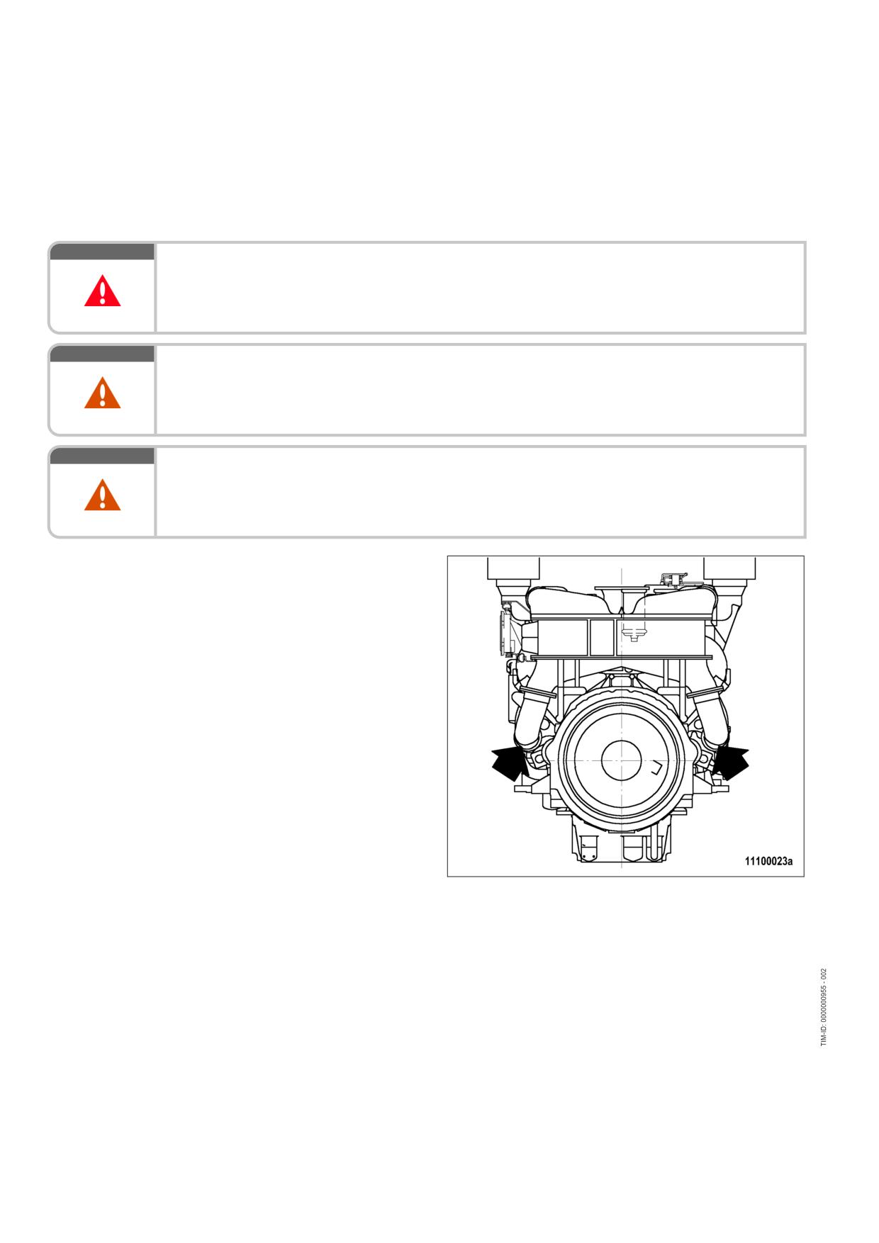
7.9
Charge-Air Cooling
7.9.1
Intercooler - Check drain for coolant leakage and obstruction
DANGER
Unguarded rotating and moving engine components.
Risk of serious injury - danger to life!
• Take special care when working on a running engine.
WARNING
Engine noise above 85 dB (A).
Risk of damage to hearing!
• Wear ear protectors.
WARNING
Compressed air
Risk of injury!
• Do not direct compressed-air jet at persons.
• Wear protective goggles / safety mask and ear protectors.
Intercooler - Check drain for
coolant leakage and obstruction
1.
Verify that air emerges from condensate
drain bore(s) on left and right engine sides
at driving end when engine is running. If no
air emerges:
• Clean drain bore(s)
• Blow out with compressed air
2.
If a large amount of coolant is continuously
discharged, the intercooler is leaking. Con-
tact Service.
Emergency measures prior to engine start with a leaking intercooler
1.
Remove injectors (→ Page 78).
2.
Bar engine manually (→ Page 63).
3.
Crank engine on starting system to blow out combustion chambers (→ Page 64).
4.
Install injectors (→ Page 78).
92 | Task Description | MS150064/01E 2011-11
7.10
Air Filter
7.10.1
Air filter - Replacement
Special tools, Material, Spare parts
Designation / Use
Part No.
Qty.
Air filter
(→ Spare Parts Catalog)
Air filter - Replacement
1.
Remove air filter and install new one (→ Page 94).
2.
Reset signal ring of service indicator (→ Page 95).
MS150064/01E 2011-11 | Task Description | 93
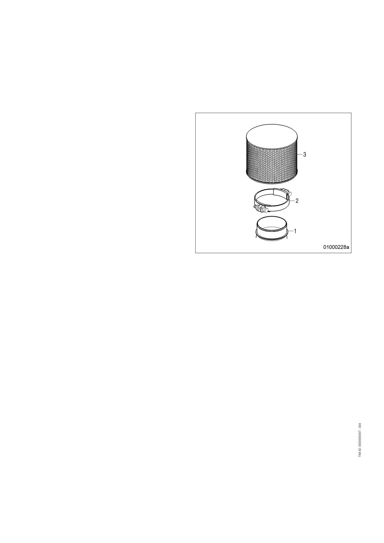
7.10.2
Air filter - Removal and installation
Preconditions
☑ Engine is stopped and starting disabled.
Air filter - Removal and installation
1.
Release clamp (2).
2.
Remove air filter (3) and clamp (2) from
flange of intake housing (1).
3.
Verify that there are no objects in the flange
of the intake housing (1) and clean it.
4.
Place new air filter (3) with clamp (2) onto
intake housing (1).
5.
Tighten clamp (2).
94 | Task Description | MS150064/01E 2011-11
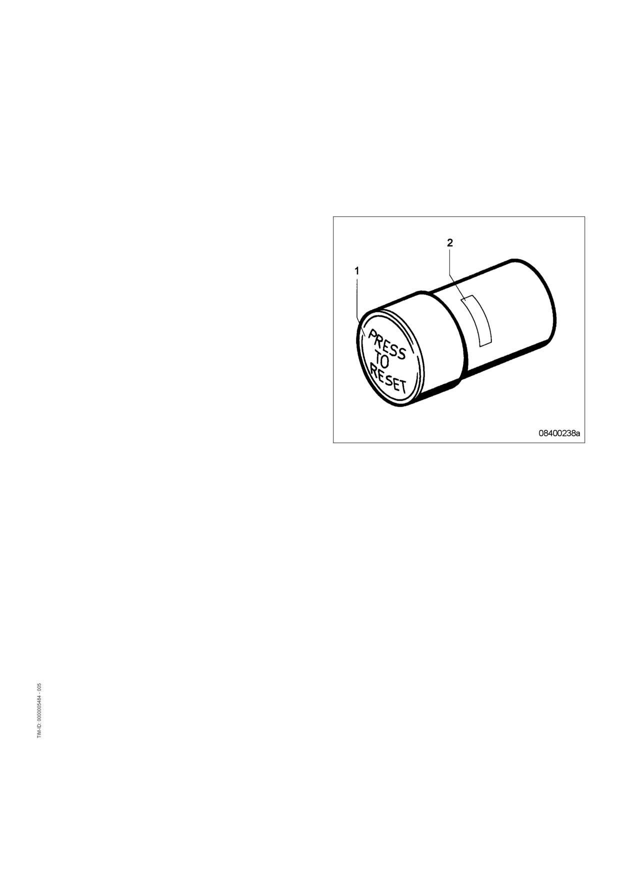
7.11
Air Intake
7.11.1
Contamination indicator - Signal ring position check
Preconditions
☑ Engine is stopped and starting disabled.
Checking signal ring position
1.
If the signal ring is completely visible in the
control window (2), replace air filter
(→ Page 93).
2.
After installation of new filter, press reset
button (1).
Result:
Engaged piston with signal ring moves back
to initial position.
MS150064/01E 2011-11 | Task Description | 95
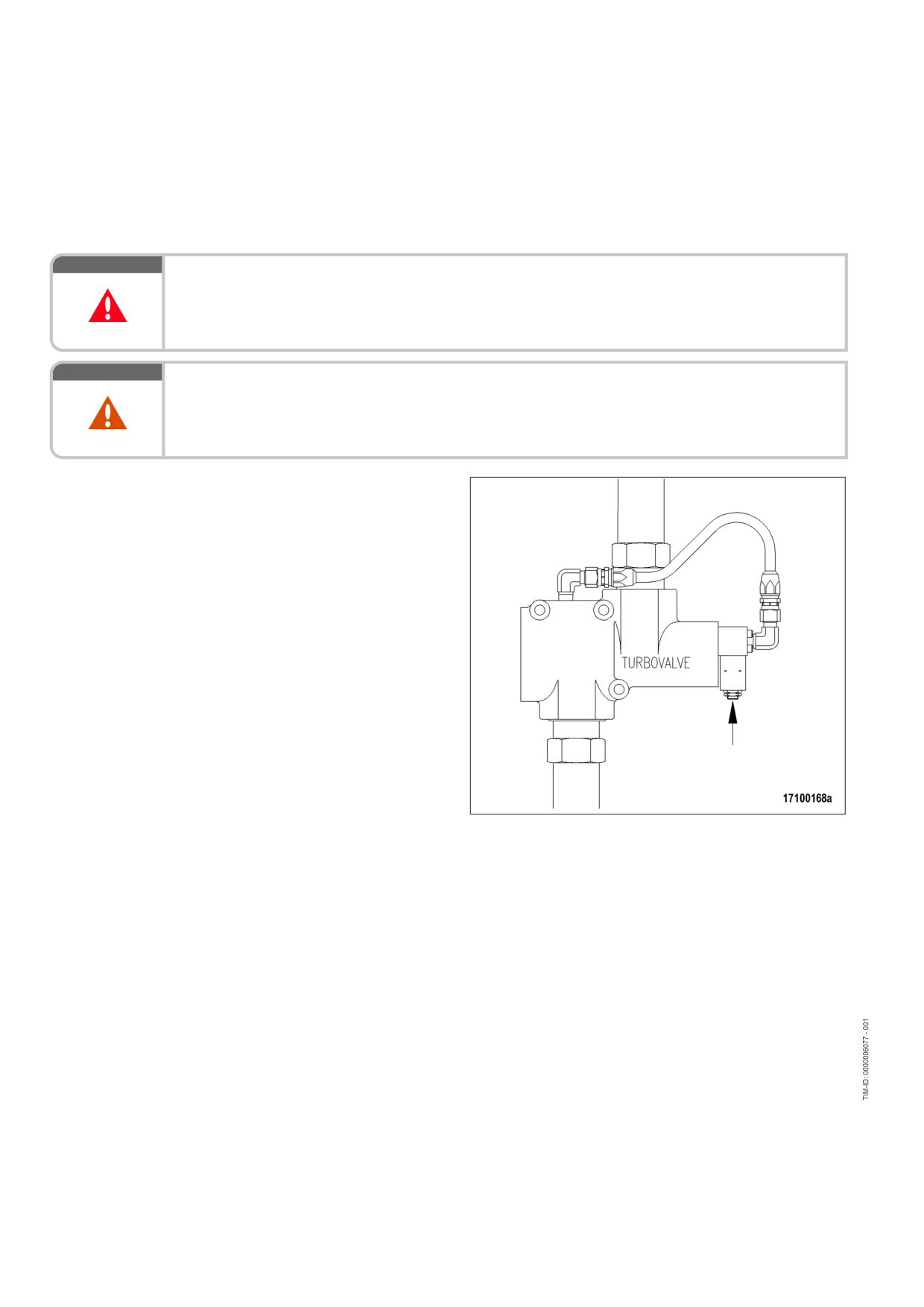
7.12
Starting Equipment
7.12.1
Air starter - Manual operation
DANGER
Unguarded rotating and moving engine components.
Risk of serious injury - danger to life!
• Before barring or starting the engine, make sure that nobody is in the danger zone.
WARNING
Engine noise above 85 dB (A).
Risk of damage to hearing!
• Wear ear protectors.
Air starter - Manual operation
1.
Operate pushbutton for manual start (ar-
row) and hold.
2.
Allow compressed air to enter the air start-
er, until the engine fires evenly.
3.
Release pushbutton.
96 | Task Description | MS150064/01E 2011-11
7.12.2
Starter - Condition check
Preconditions
☑ Engine is stopped and starting disabled.
Checking starter condition
1.
Check securing screws of starter for secure seating and tighten if required.
2.
Check wiring (→ Page 125).
MS150064/01E 2011-11 | Task Description | 97
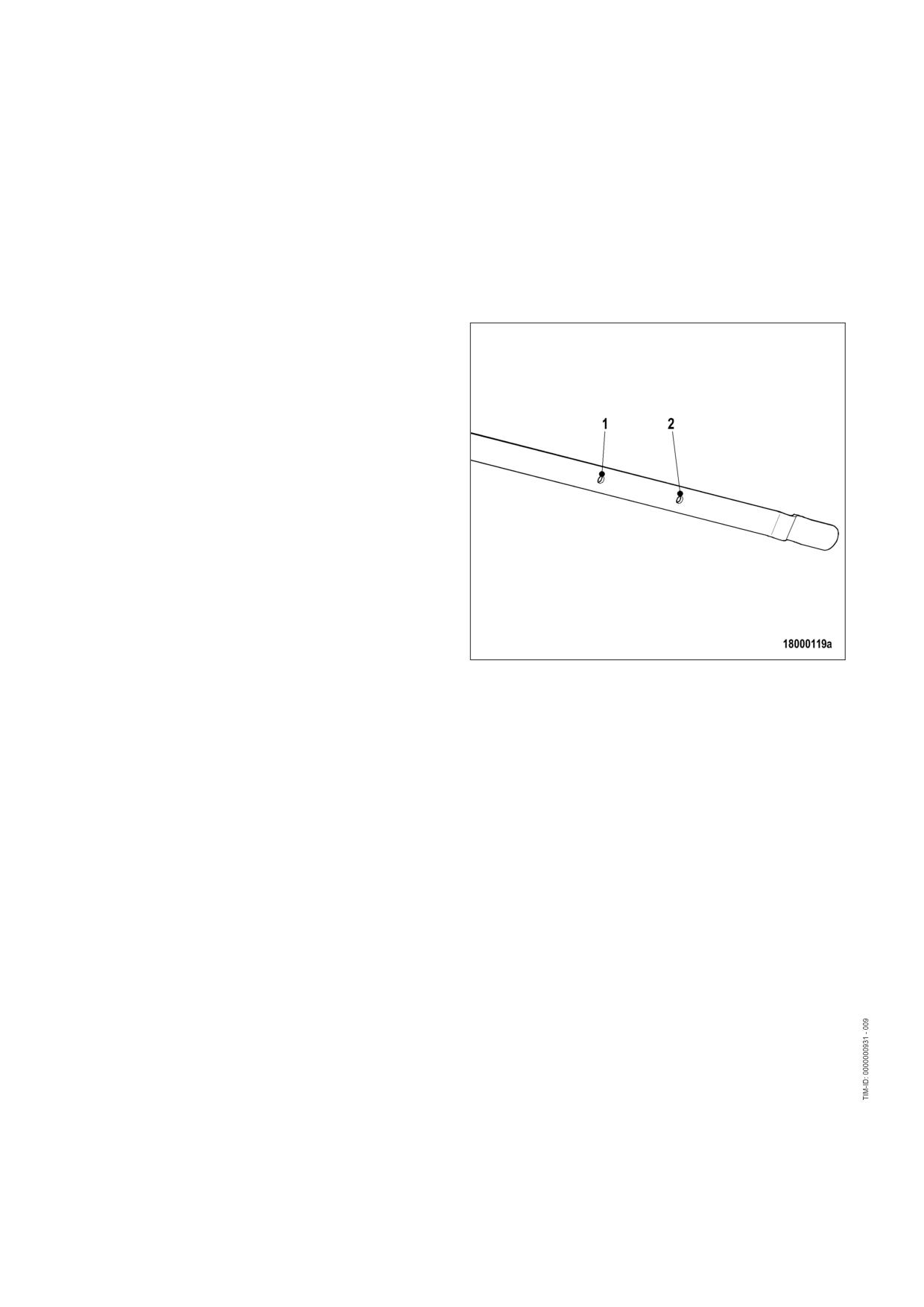
7.13
Lube Oil System, Lube Oil Circuit
7.13.1
Engine oil level - Check
Preconditions
☑ Engine shut down and starting disabled.
Checking oil level prior to engine
start
1.
Withdraw oil dipstick from guide tube and
wipe it.
2.
Insert oil dipstick into guide tube up to stop,
withdraw after approx. 10 seconds and
check oil level.
Note:
After extended standstill, the oil level may
exceed the mark (1) by up to 2 cm. This
can be caused by oil flowing from e.g. oil fil-
ter or heat exchanger back to the oil pan.
3.
The oil level must reach mark (1) or exceed
mark (1) by up to 2 cm.
4.
Top up with oil to mark (1) as necessary
(→ Page 99).
5.
Insert oil dipstick into guide tube up to the
stop.
Checking oil level after the engine is stopped
1.
5 minutes after stopping the engine, remove oil dipstick from the guide tube and wipe it.
2.
Insert oil dipstick into guide tube up to stop, withdraw after approx. 10 seconds and check oil level.
3.
Oil level must be between marks (1) and (2).
4.
Top up with oil to mark (1) as necessary (→ Page 99).
5.
Insert oil dipstick into guide tube up to the stop.
98 | Task Description | MS150064/01E 2011-11
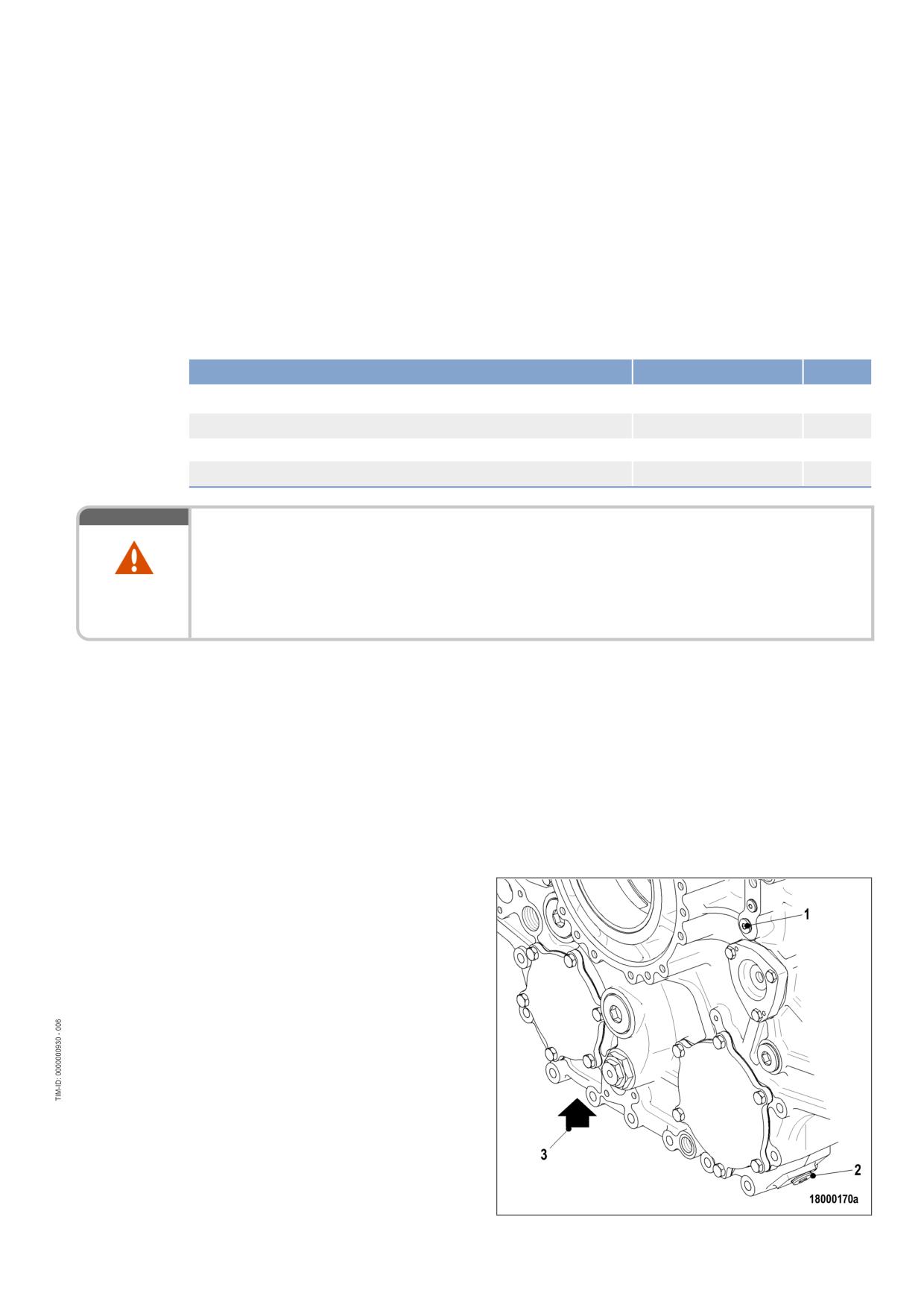
7.13.2
Engine oil - Change
Preconditions
☑ Engine is stopped and starting disabled.
☑ Engine is at operating temperature.
☑ MTU Fluids and Lubricants Specifications (A001061/..) are available.
Special tools, Material, Spare parts
Designation / Use
Part No.
Qty.
Torque wrench, 40-200 Nm
F30027337
1
Ratchet adapter
F30027341
1
Engine oil
Sealing ring
(→ Spare Parts Catalog)
WARNING
Hot oil.
Oil can contain combustion residues which are harmful to health.
Risk of injury and poisoning!
• Wear protective clothing, gloves, and goggles / safety mask.
• Avoid contact with skin.
• Do not inhale oil vapor.
Oil change without semirotary hand pump: Draining engine oil at drain plug(s) on oil
pan
1.
Provide a suitable container in which to collect the engine oil.
2.
Remove drain plug(s) and drain engine oil.
3.
Install drain plug(s) with new sealing ring.
Oil change with semirotary hand pump: Extracting engine oil
1.
Provide a suitable container in which to collect the engine oil.
2.
Extract all engine oil from oil pan using the semirotary hand pump.
Draining residual oil from
equipment carrier (only with
unscheduled engine oil change)
1.
Provide a suitable container in which to col-
lect the engine oil.
2.
Remove drain plug (1) and drain engine oil
from engine oil heat exchanger and from
engine oil filter.
3.
Remove drain plugs (2) and (3) and drain
engine oil.
4.
Replace engine oil filter (→ Page 102).
5.
Install drain plug(s) with new sealing ring.
MS150064/01E 2011-11 | Task Description | 99
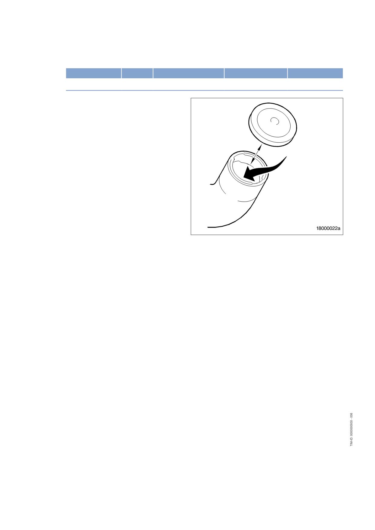
6.
Tighten drain plugs (2) and (3) with torque wrench to the specified torque.
Name
Size
Type
Lubricant
Value/Standard
Screw
M26 x 1.5
Tightening torque
(Engine oil)
100 Nm +10 Nm
Filling with new engine oil
1.
Open cap on filler neck.
2.
Pour in engine oil at filler neck up to “max.”
mark on oil dipstick.
3.
Close cap on filler neck.
4.
Check engine oil level (→ Page 98).
5.
After oil change and oil filter replacement,
bar engine with starting system
(→ Page 64).
100 | Task Description | MS150064/01E 2011-11
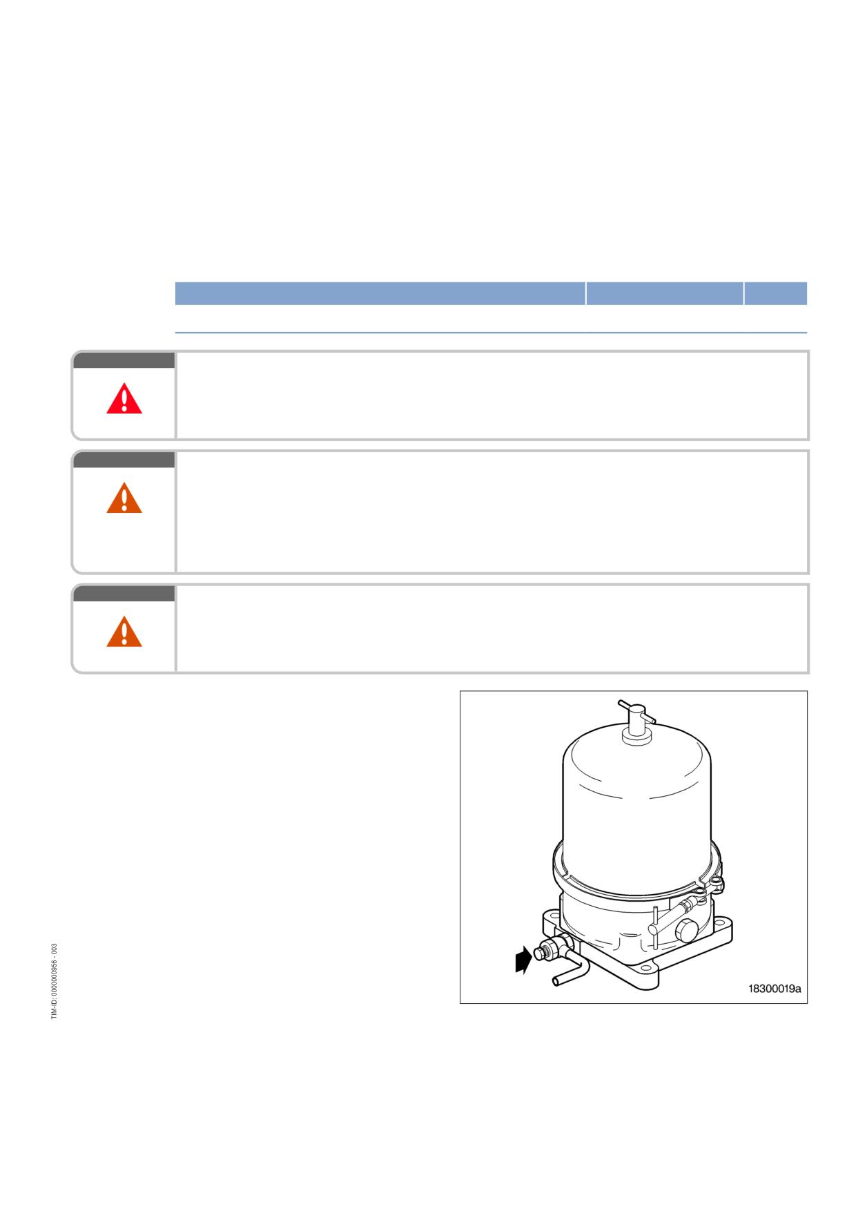
7.13.3
Engine oil - Sample extraction and analysis
Preconditions
☑ MTU Fluids and Lubricants Specifications (A001061/..) are available.
Special tools, Material, Spare parts
Designation / Use
Part No.
Qty.
MTU test kit
5605892099/00
1
DANGER
Unguarded rotating and moving engine components.
Risk of serious injury - danger to life!
• Take special care when working on a running engine.
WARNING
Hot oil.
Oil can contain combustion residues which are harmful to health.
Risk of injury and poisoning!
• Wear protective clothing, gloves, and goggles / safety mask.
• Avoid contact with skin.
• Do not inhale oil vapor.
WARNING
Engine noise above 85 dB (A).
Risk of damage to hearing!
• Wear ear protectors.
Engine oil sample extraction and
analysis
1.
With the engine running at operating tem-
perature, open screw on flange of centrifu-
gal oil filter by 1 to 2 rotations.
2.
Drain approx. 2 liters engine oil to flush out
the oil sludge.
3.
Drain approx. 1 liter engine oil into a clean
container.
4.
Close screw.
5.
Using the equipment and chemicals of the
MTU test kit, examine oil for:
• Dispersing capacity (spot test);
• Water content;
• Fuel dilution.
MS150064/01E 2011-11 | Task Description | 101
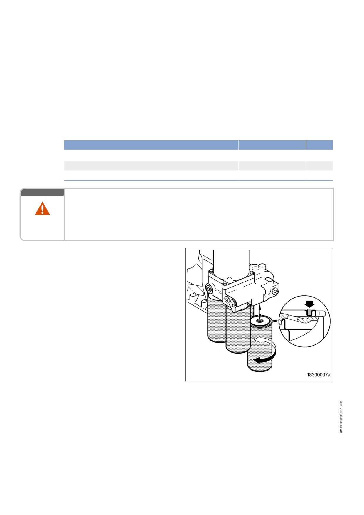
7.14
Oil Filtration / Cooling
7.14.1
Engine oil filter - Replacement
Preconditions
☑ Engine is stopped and starting disabled.
Special tools, Material, Spare parts
Designation / Use
Part No.
Qty.
Filter wrench
F30379104
Engine oil
Oil filter
(→ Spare Parts Catalog)
WARNING
Hot oil.
Oil can contain combustion residues which are harmful to health.
Risk of injury and poisoning!
• Wear protective clothing, gloves, and goggles / safety mask.
• Avoid contact with skin.
• Do not inhale oil vapor.
Replacing engine oil filter
1.
Remove oil filter using filter wrench.
2.
Clean sealing surface on connecting piece.
3.
Check condition of new oil filter sealing ring
and coat it with engine oil.
4.
Screw on and tighten new engine oil filter
by hand.
5.
Replace other engine oil filters in the same
way.
6.
Crank engine on starting system after every
oil change and filter replacement
(→ Page 64).
7.
Check engine oil level (→ Page 98).
102 | Task Description | MS150064/01E 2011-11
7.14.2
Centrifugal oil filter - Cleaning and filter sleeve replacement
Preconditions
☑ Engine shut down and starting disabled.
Special tools, Material, Spare parts
Designation / Use
Part No.
Qty.
Filter wrench
F30379104
1
Torque wrench, 6-50 Nm
F30027336
1
Ratchet adapter
F30027339
1
Cold cleaner (Hakutex 60)
50602
1
Grease (Kluthe Hakuform 30-10/emulsifier)
X00029933
1
Filter sleeve
(→ Spare Parts Catalog)
Sealing ring
(→ Spare Parts Catalog)
Sealing ring
(→ Spare Parts Catalog)
WARNING
Hot oil.
Oil can contain combustion residues which are harmful to health.
Risk of injury and poisoning!
• Wear protective clothing, gloves, and goggles / safety mask.
• Avoid contact with skin.
• Do not inhale oil vapor.
WARNING
Compressed air
Risk of injury!
• Do not direct compressed-air jet at persons.
• Wear protective goggles / safety mask and ear protectors.
MS150064/01E 2011-11 | Task Description | 103
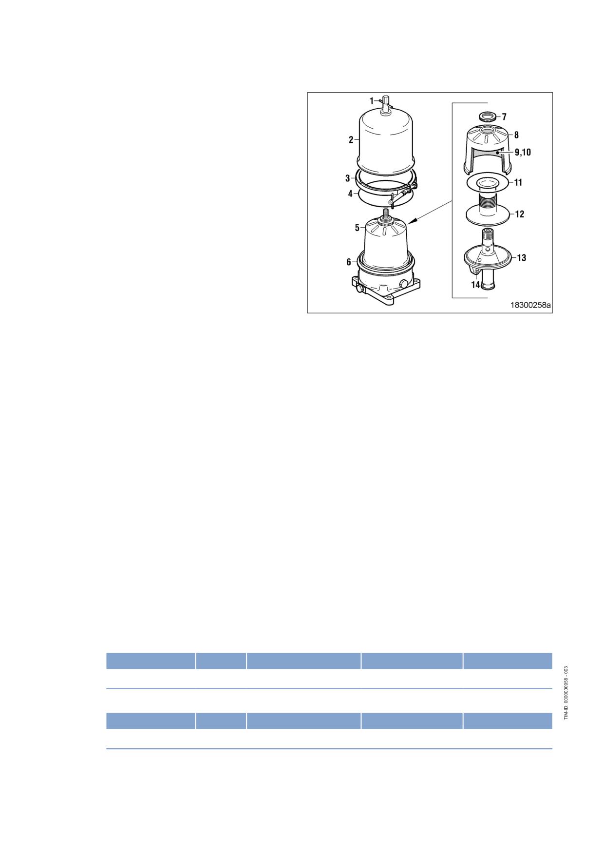
Cleaning centrifugal oil filter and
replacing filter sleeve
1.
Undo screw (1) and remove.
2.
Remove clamp (3) and take off hood (2).
3.
Carefully remove rotor (5) from housing.
4.
Hold rotor assembly (5) firmly in position
with filter wrench and undo knurled nut (7).
5.
Take off rotor cap (8).
6.
Remove filter sleeve (9), stiffener plate (10)
and sealing ring (11).
7.
Measure thickness of oil residues on filter
sleeve.
8.
If maximum layer thickness of oil residues
exceeds 30 mm, shorten maintenance in-
terval.
9.
Remove standpipe (12) from lower rotor
section (13).
10.
Wash hood (2), rotor cap (8), stiffener
plate, (10) standpipe (12), rotor lower sec-
tion (13) and nozzles (14) with cold cleaner
and blow out with compressed air. Do not
use sharp objects for cleaning.
11.
Check nozzles (14) for obstructions.
12.
Press standpipe (12) onto rotor lower sec-
tion (13).
13.
Insert new filter sleeve (9) with stiffener
plate (10) into rotor cap (8), ensuring that
smooth surface of filter sleeve (9) faces ro-
tor cap (8).
14.
Check sealing ring (11), replace if necessa-
ry. Coat sealing ring with grease and insert
in groove of rotor cap (8).
15.
Place rotor cap (8) onto standpipe (12).
16.
Hold rotor assembly (5) firmly in position
with filter wrench and tighten knurled
nut (7).
17.
Lubricate bearings of rotor (5) with oil, in-
sert into housing (6) and check for ease of
movement.
18.
Check sealing ring (4), replace if necessary.
Fit sealing ring on housing (6).
19.
Fit hood (2).
20.
Tighten screw (1) by hand.
21.
Install clamp (3) and tighten to specified torque using a torque wrench.
Name
Size
Type
Lubricant
Value/Standard
Clamp
Tightening torque
6 Nm + 1 Nm
22.
Tighten screw (1) to specified torque using a torque wrench.
Name
Size
Type
Lubricant
Value/Standard
Screw
Tightening torque
6 Nm + 1 Nm
104 | Task Description | MS150064/01E 2011-11
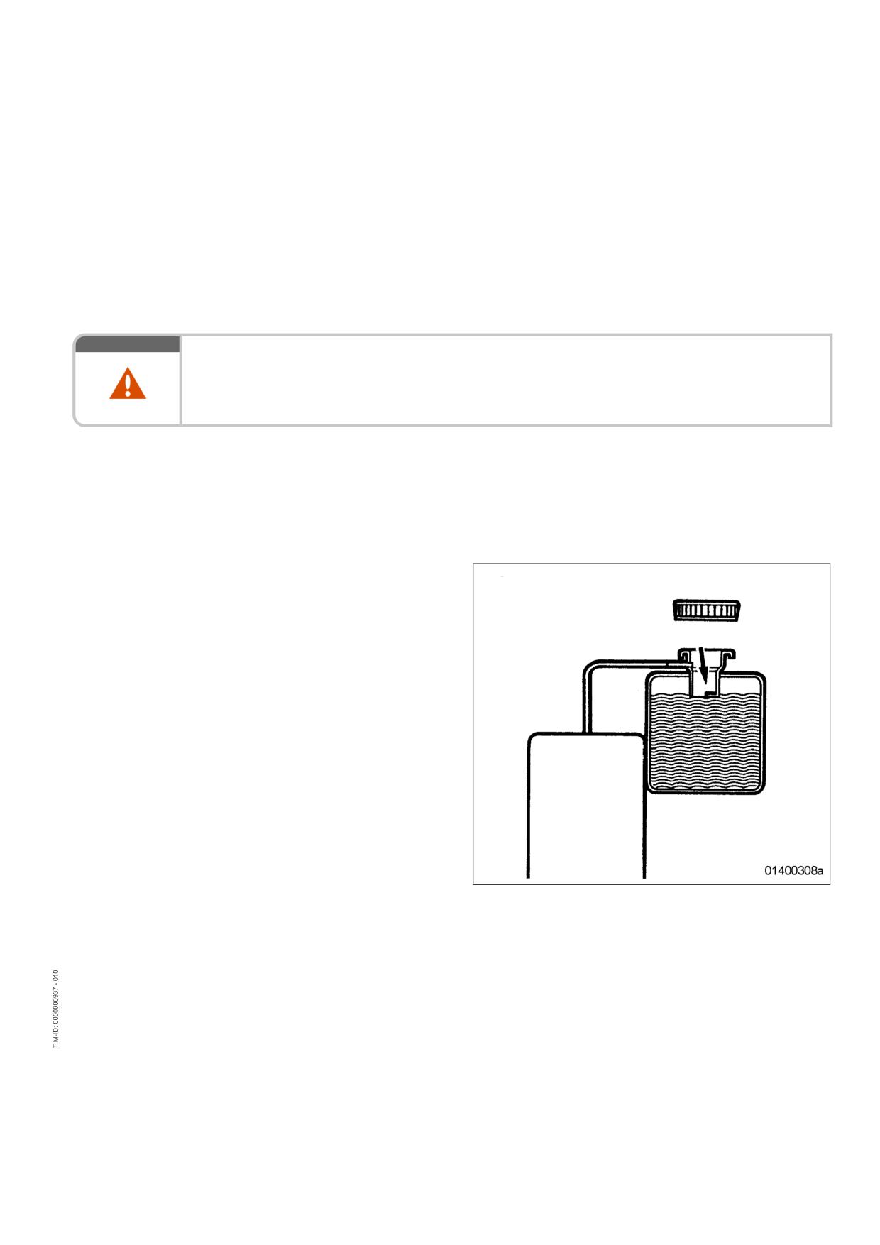
7.15
Coolant Circuit, General, High-Temperature Circuit
7.15.1
Coolant level - Check
Preconditions
☑ Engine shut down and starting disabled.
☑ MTU Fluids and Lubricants Specifications (A001061/..) are available.
WARNING
Coolant is hot and under pressure.
Risk of injury and scalding!
• Let the engine cool down.
• Wear protective clothing, gloves, and goggles / safety mask.
Checking coolant level at filler neck:
1.
Turn breather valve on coolant expansion tank counterclockwise to the first stop and allow pressure to
escape.
2.
Continue to turn breather valve counterclockwise and remove.
3.
Check coolant level (coolant must be visible at the lower edge of the cast-in eye).
Checking coolant level at remote
cooler:
1.
Check coolant level (coolant must be visible
at marking plate).
2.
Top up coolant if necessary (→ Page 108).
3.
Check and clean breather valve.
4.
Place breather valve on filler neck and
close.
Coolant level check by means of level sensor:
1.
Switch on engine control system and check readings on the display.
2.
Top up coolant if necessary (→ Page 108).
MS150064/01E 2011-11 | Task Description | 105
7.15.2
Engine coolant - Change
Special tools, Material, Spare parts
Designation / Use
Part No.
Qty.
Engine coolant
Changing engine coolant
1.
Drain engine coolant (→ Page 107).
2.
Fill with engine coolant (→ Page 108).
106 | Task Description | MS150064/01E 2011-11
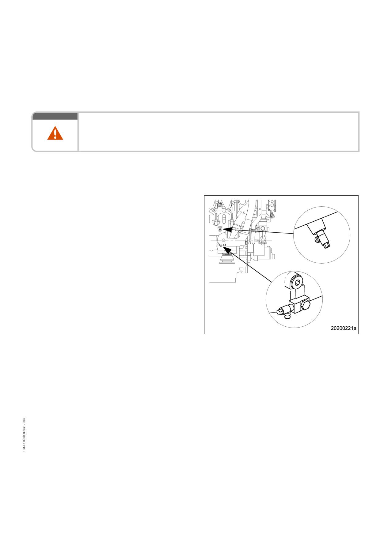
7.15.3
Engine coolant - Draining
Preconditions
☑ Engine is stopped and starting disabled.
WARNING
Coolant is hot and under pressure.
Risk of injury and scalding!
• Let the engine cool down.
• Wear protective clothing, gloves, and goggles / safety mask.
Preparatory steps
1.
Provide an appropriate container to drain the coolant into.
2.
Switch off preheating unit.
Engine coolant - Draining
1.
Turn breather valve of filler neck on coolant
expansion tank counterclockwise to first
stop and allow pressure to escape.
2.
Continue to turn breather valve counter-
clockwise and remove.
3.
Draw off separated corrosion inhibitor oil in
expansion tank through the filler neck.
4.
Open drain valves and/or drain plugs and
drain coolant at the following points:
• At preheating unit;
• At HT coolant pump elbow;
• On crankcase, left and right side.
5.
Close all open drain points.
6.
Set breather valve onto filler neck and close
it.
MS150064/01E 2011-11 | Task Description | 107
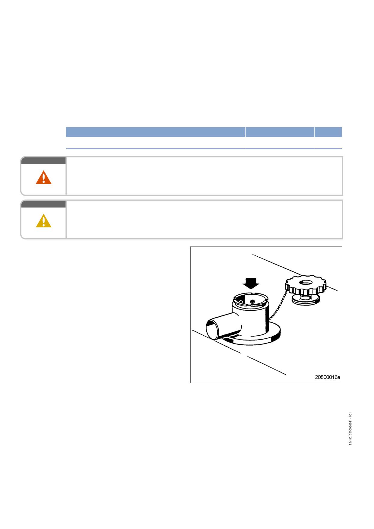
7.15.4
Engine coolant - Filling
Preconditions
☑ Engine is stopped and starting disabled.
☑ MTU Fluids and Lubricants Specifications (A001061/..) are available.
Special tools, Material, Spare parts
Designation / Use
Part No.
Qty.
Engine coolant
WARNING
Coolant is hot and under pressure.
Risk of injury and scalding!
• Let the engine cool down.
• Wear protective clothing, gloves, and goggles / safety mask.
CAUTION
Cold coolant in hot engine can cause thermal stress.
Formation of cracks in components!
• Fill / top up coolant only into cold engine.
Preparatory steps
1.
Turn breather valve of coolant expansion
tank counterclockwise until the first stop
and allow pressure to escape.
2.
Continue to turn breather valve counter-
clockwise and remove.
108 | Task Description | MS150064/01E 2011-11
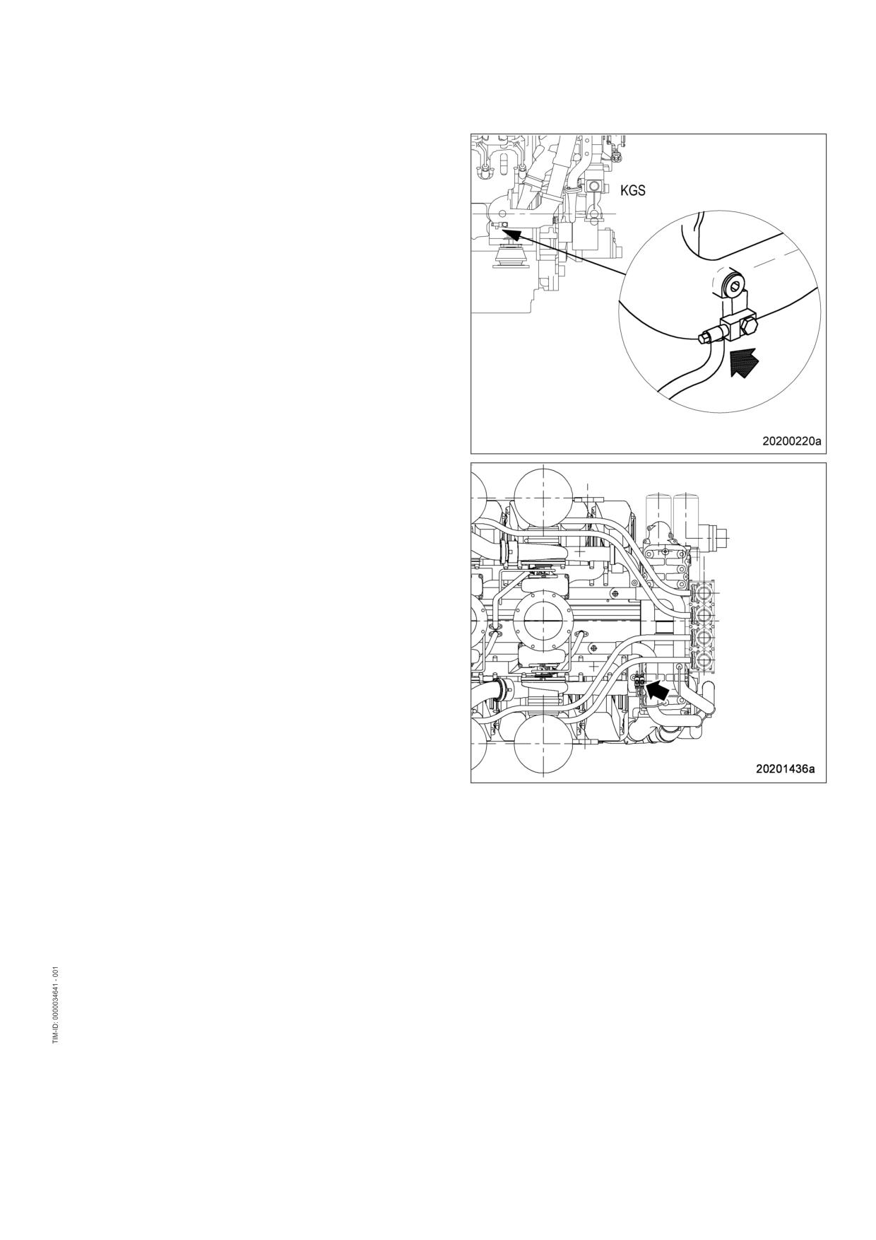
Filling with coolant using a pump
1.
Connect suitable pump and hose to engine
coolant pump drain valve (arrowed) or drain
and filling line between engine and radiator.
2.
Undo screw connection (arrowed) of the
vent line on the distributor.
3.
Open drain valve and pump coolant into en-
gine with a pressure of at least 0.5 bar until
coolant escapes from the open connection.
4.
Tighten connection (arrowed).
5.
Fill coolant expansion tank until coolant lev-
el reaches the bottom edge of the filler
neck.
6.
Close drain valve.
7.
Check proper condition of breather valve
and clean sealing faces if required.
8.
Fit breather valve and close it.
9.
Start engine (→ Page 39).
10.
After 10 seconds of running the engine
without load, shut down the engine
(→ Page 42).
11.
Turn breather valve of coolant expansion
tank counterclockwise until the first stop
and allow pressure to escape.
12.
Continue to turn breather valve counter-
clockwise and remove.
13.
Check coolant level (→ Page 105) and top
up engine coolant as required:
a) Add coolant via filler neck on expansion
tank until the coolant level at bottom
edge of filler neck remains constant.
b) Check proper condition of breather
valve and clean sealing faces if re-
quired.
c) Fit breather valve and close it.
14.
Repeat the steps from "Start engine"
(→ Step 8) until coolant is no longer needed
to be topped up.
15.
Disconnect pump and hose.
MS150064/01E 2011-11 | Task Description | 109
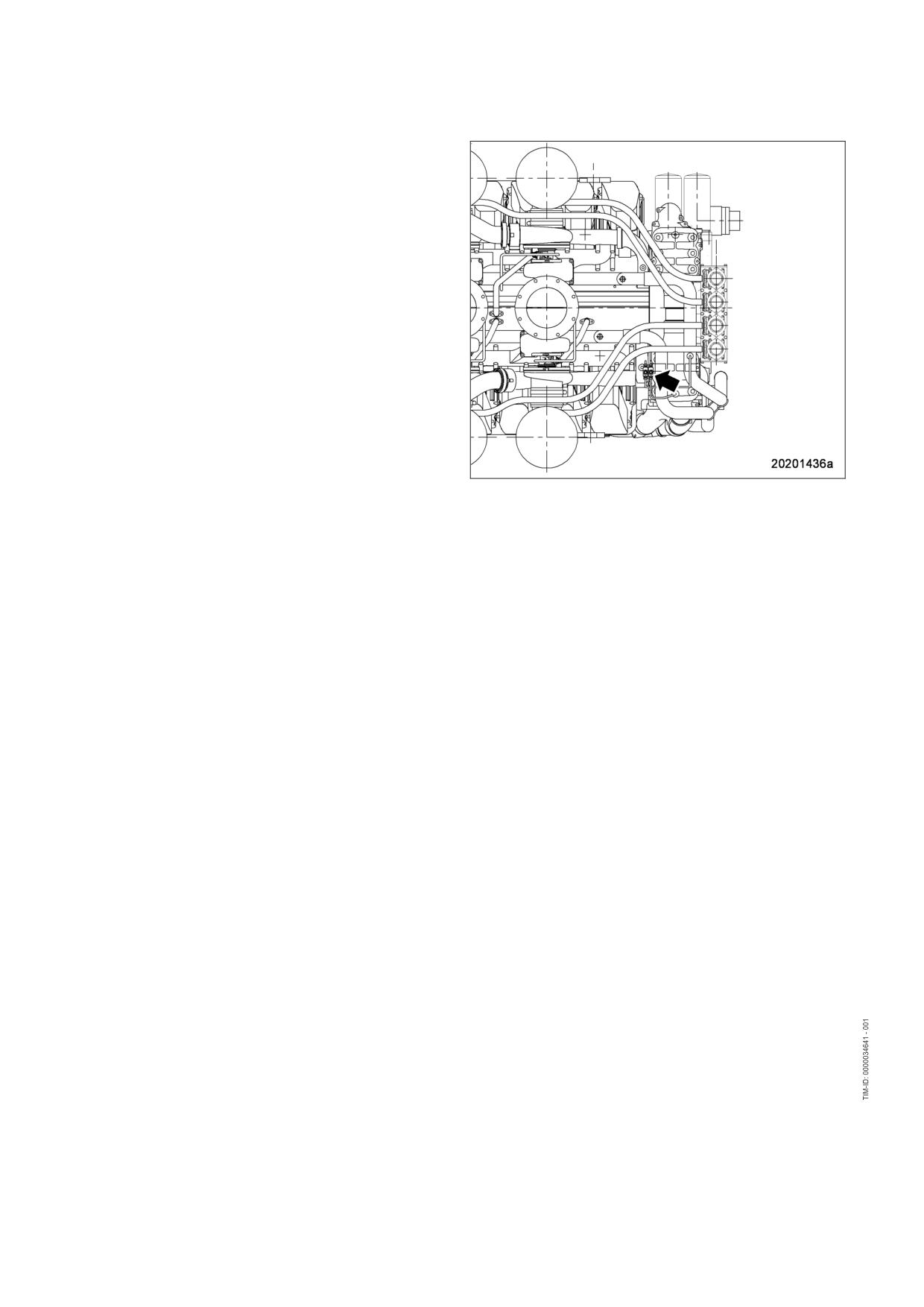
Alternatively: Filling with coolant
through filler neck
1.
Undo screw connection (arrowed) of the
vent line on the distributor.
2.
Fill in coolant via filler neck on expansion
tank until the coolant level at bottom edge
of filler neck remains constant.
3.
Tighten connection (arrowed).
4.
Check proper condition of breather valve
and clean sealing faces if required.
5.
Fit breather valve and close it.
6.
Start engine (→ Page 39).
7.
After 10 seconds of running the engine
without load, shut down the engine
(→ Page 42).
8.
Turn breather valve of coolant expansion
tank counterclockwise until the first stop
and allow pressure to escape.
9.
Turn breather valve counterclockwise and
remove.
10.
Check coolant level (→ Page 105) and top
up with coolant through the filler neck if re-
quired:
a) Add coolant via filler neck on expansion
tank until the coolant level at bottom
edge of filler neck remains constant.
b) Check proper condition of breather
valve and clean sealing faces if re-
quired.
c) Fit breather valve and close it.
11.
Repeat the steps from "Start engine"
(→ Step 6) until coolant is no longer needed
to be topped up.
Final steps
1.
Start the engine and run it without load for some minutes.
2.
Check coolant level (→ Page 105) and top up engine coolant as required.
110 | Task Description | MS150064/01E 2011-11
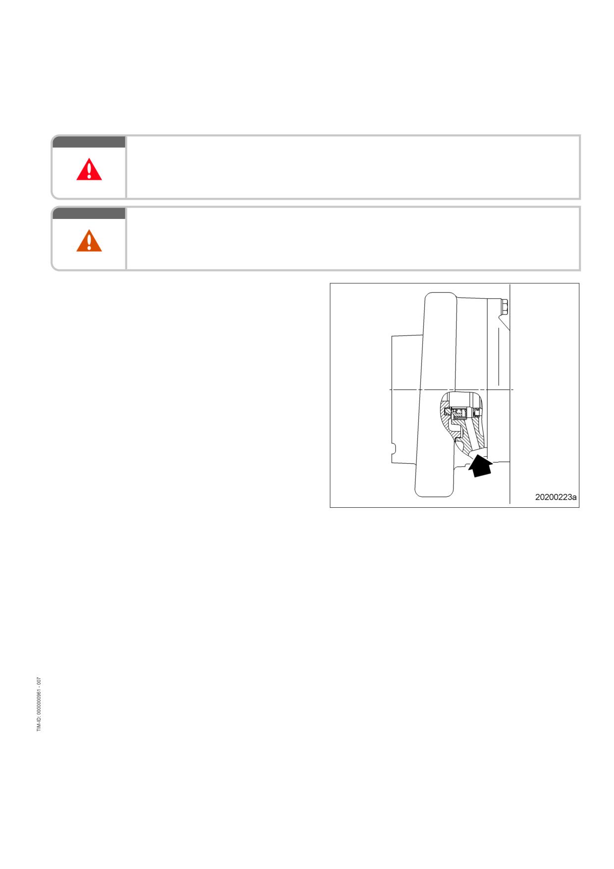
7.15.5
Engine coolant pump - Relief bore check
DANGER
Unguarded rotating and moving engine components.
Risk of serious injury - danger to life!
• Take special care when working on a running engine.
WARNING
Engine noise above 85 dB (A).
Risk of damage to hearing!
• Wear ear protectors.
Checking relief bore on engine
coolant pump
1.
Checking relief bore for oil and coolant dis-
charge.
2.
Stop engine (→ Page 42) and disable en-
gine start, observe general safety instruc-
tions for maintenance and repair.
3.
Clean the relief bore with a wire if it is dirty.
• Permissible coolant discharge: up to 10
drops per hour.
• Permissible oil discharge: up to 5 drops
per hour.
4.
If discharge exceeds the specified limits:
Contact Service.
MS150064/01E 2011-11 | Task Description | 111
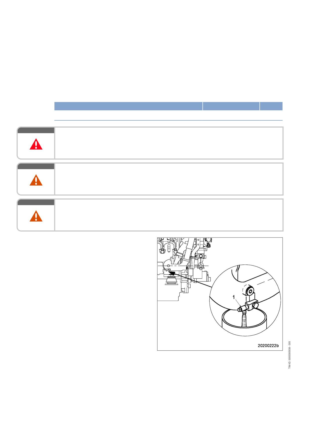
7.15.6
Coolant - Sample extraction and analysis
Preconditions
☑ MTU Fluids and Lubricants Specifications (A001061/..) are available.
Special tools, Material, Spare parts
Designation / Use
Part No.
Qty.
MTU test kit
5605892099/00
1
DANGER
Unguarded rotating and moving engine components.
Risk of serious injury - danger to life!
• Take special care when working on a running engine.
WARNING
Coolant is hot and under pressure.
Risk of injury and scalding!
• Let the engine cool down.
• Wear protective clothing, gloves, and goggles / safety mask.
WARNING
Engine noise above 85 dB (A).
Risk of damage to hearing!
• Wear ear protectors.
Coolant sample extraction and
analysis
1.
With the engine running, open drain valve
(1).
2.
Flush sample-extraction point by draining
approx. 1 liter coolant.
3.
Drain approx. 1 liter coolant into a clean
container.
4.
Close drain valve (1).
5.
Using the equipment and chemicals of the
MTU test kit, check the coolant for:
• Antifreeze concentration
• Corrosion inhibitor concentration
• pH value.
6.
For coolant change intervals, see (→ MTU
Fluids and Lubricants Specifications.)
112 | Task Description | MS150064/01E 2011-11
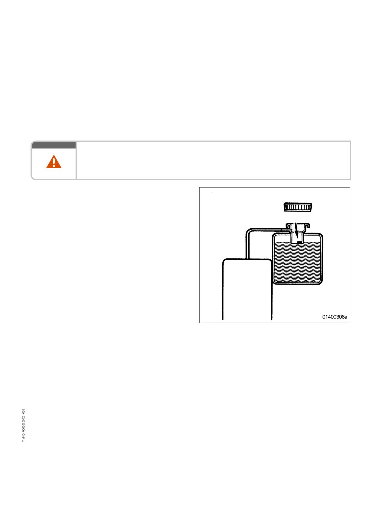
7.16
Low-Temperature Circuit
7.16.1
Charge-air coolant - Level check
Preconditions
☑ Engine is stopped and starting disabled.
☑ MTU Fluids and Lubricants Specifications (A001061/..) are available.
WARNING
Coolant is hot and under pressure.
Risk of injury and scalding!
• Let the engine cool down.
• Wear protective clothing, gloves, and goggles / safety mask.
Checking charge-air coolant level
at filler neck:
1.
Turn breather valve on coolant expansion
tank counterclockwise to the first stop and
allow pressure to escape.
2.
Continue to turn breather valve counter-
clockwise and remove.
3.
Check coolant level (coolant must be visible
at marking plate).
4.
Top up coolant if necessary (→ Page 116).
5.
Check proper condition of breather valve,
clean sealing faces if required.
6.
Fit breather valve and close it.
Checking charge-air coolant level by means of level sensor:
1.
Switch on engine control system and check display (coolant level is automatically monitored by engine
control system).
2.
Top up coolant if necessary (→ Page 116).
MS150064/01E 2011-11 | Task Description | 113
7.16.2
Charge-air coolant - Change
Special tools, Material, Spare parts
Designation / Use
Part No.
Qty.
Charge-air coolant
Charge-air coolant - Change
1.
Drain charge-air coolant (→ Page 115).
2.
Fill with charge-air coolant (→ Page 116).
114 | Task Description | MS150064/01E 2011-11
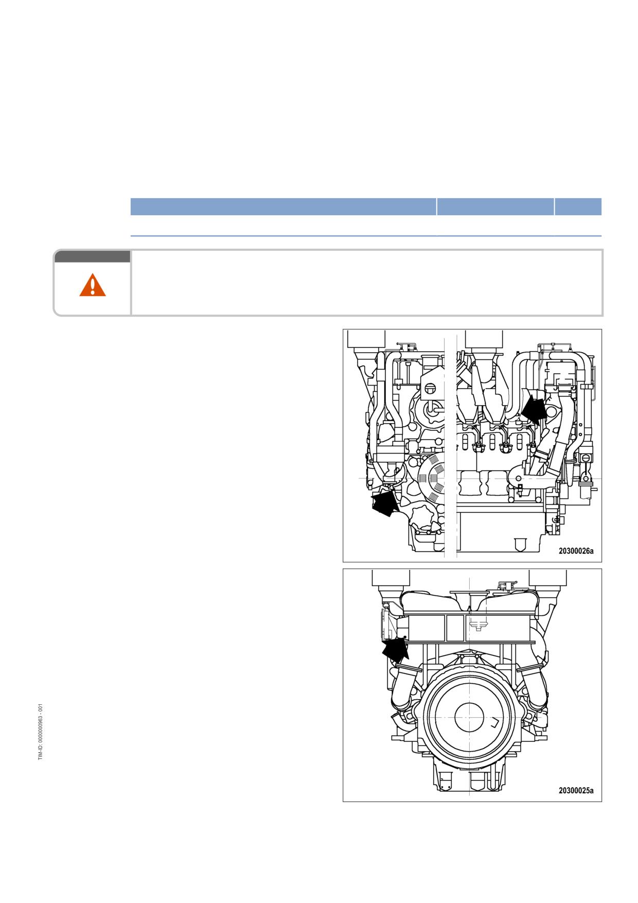
7.16.3
Charge-air coolant - Draining
Preconditions
☑ Engine is stopped and starting disabled.
Special tools, Material, Spare parts
Designation / Use
Part No.
Qty.
Sealing ring
(→ Spare Parts Catalog)
WARNING
Coolant is hot and under pressure.
Risk of injury and scalding!
• Let the engine cool down.
• Wear protective clothing, gloves, and goggles / safety mask.
Charge-air coolant - Draining
1.
Provide an appropriate container to drain
the coolant into.
2.
Turn breather valve of coolant expansion
tank counterclockwise until the first stop
and allow pressure to escape.
3.
Continue to turn breather valve counter-
clockwise and remove.
4.
Draw off precipitated corrosion inhibitor oil
from the expansion tank through filler neck.
5.
Open drain cocks and drain plugs and drain
coolant at the following points:
• at the LT cooling pump
• at the coolant lines to and from the inter-
cooler
6.
Draining of residual coolant:
• at the intercooler
7.
Close all drain valves and install drain plugs
with new sealing rings.
8.
Set breather valve onto filler neck and close
it.
MS150064/01E 2011-11 | Task Description | 115
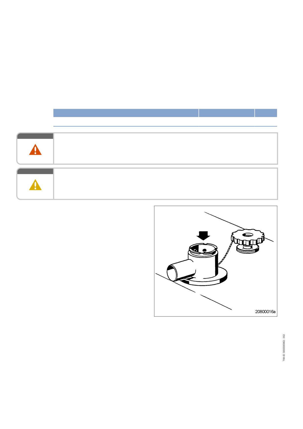
7.16.4
Charge-air coolant - Filling
Preconditions
☑ Engine is stopped and starting disabled.
☑ MTU Fluids and Lubricants Specifications (A001061/..) are available.
Special tools, Material, Spare parts
Designation / Use
Part No.
Qty.
Charge-air coolant
WARNING
Coolant is hot and under pressure.
Risk of injury and scalding!
• Let the engine cool down.
• Wear protective clothing, gloves, and goggles / safety mask.
CAUTION
Cold coolant in hot engine can cause thermal stress.
Formation of cracks in components!
• Fill / top up coolant only into cold engine.
Preparatory steps
1.
Turn breather valve of coolant expansion
tank counterclockwise until the first stop
and allow pressure to escape.
2.
Continue to turn breather valve counter-
clockwise and remove.
116 | Task Description | MS150064/01E 2011-11
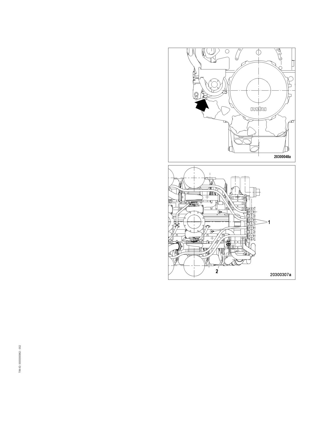
Filling with charge-air coolant using
a pump
1.
Connect suitable pump and hose to charge-
air coolant pump drain valve (arrowed) or
drain and filling line between engine and ra-
diator.
2.
Undo plug screws (1) on coolant lines to
and from intercooler and connection (2) of
the vent line on the distributor.
3.
Open drain valve and pump coolant into en-
gine with a pressure of at least 0.5 bar until
coolant escapes from the open connec-
tions.
4.
Tighten plug screws (1) and connection (2)
in sequence from top to bottom.
5.
Fill coolant expansion tank until coolant lev-
el reaches the bottom edge of the filler
neck.
6.
Close drain valve.
7.
Check proper condition of breather valve
and clean sealing faces if required.
8.
Install and close breather valve.
9.
Start engine (→ Page 39).
10.
After the engine has run at unloaded condi-
tion for 10 seconds, stop engine
(→ Page 42).
11.
Turn breather valve of coolant expansion
tank counterclockwise until the first stop
and allow pressure to escape.
12.
Continue to turn breather valve counter-
clockwise and remove.
13.
Check coolant level (→ Page 113) and top
up if required:
a) Add coolant via filler neck on expansion
tank until the coolant level at bottom
edge of filler neck remains constant.
b) Check proper condition of breather
valve and clean sealing faces if re-
quired.
c) Install and close breather valve.
14.
Repeat the steps from "Start engine"
(→ Step 8) until coolant no longer needs to
be topped up.
15.
Disconnect pump and hose.
MS150064/01E 2011-11 | Task Description | 117
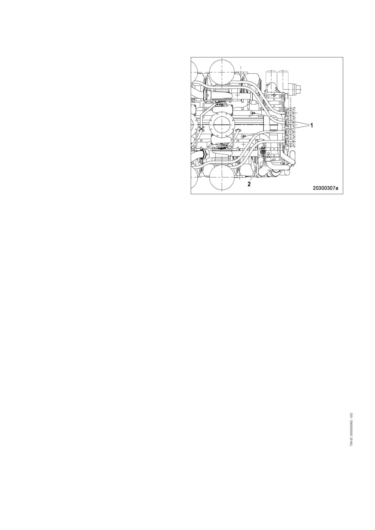
Alternatively: Filling with coolant
through filler neck
1.
Undo plug screws (1) on coolant lines to
and from intercooler and connection (2) of
the vent line on the distributor.
2.
Fill in coolant via filler neck on expansion
tank until the coolant level at bottom edge
of filler neck remains constant.
3.
Tighten plug screws (1) and connection (2)
in sequence from top to bottom.
4.
Check proper condition of breather valve
and clean sealing faces if required.
5.
Install and close breather valve.
6.
Start engine (→ Page 39).
7.
After the engine has run at unloaded condi-
tion for 10 seconds, stop engine
(→ Page 42).
8.
Turn breather valve of coolant expansion
tank counterclockwise until the first stop
and allow pressure to escape.
9.
Turn breather valve counterclockwise and
remove.
10.
Check coolant level (→ Page 113) and top
up if required:
a) Add coolant via filler neck on expansion
tank until the coolant level at bottom
edge of filler neck remains constant.
b) Check proper condition of breather
valve and clean sealing faces if re-
quired.
c) Install and close breather valve.
11.
Repeat the steps from "Start engine"
(→ Step 6) until coolant no longer needs to
be topped up.
Final steps
1.
Start the engine and operate it at unloaded condition for some minutes.
2.
Check coolant level (→ Page 113) and top up if required.
118 | Task Description | MS150064/01E 2011-11
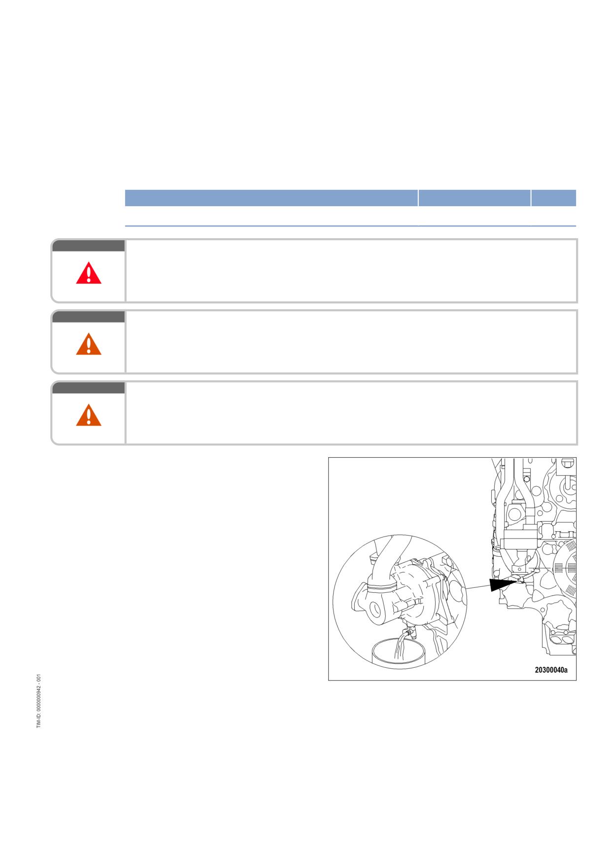
7.16.5
Charge-air coolant - Sample extraction and analysis
Preconditions
☑ MTU Fluids and Lubricants Specifications (A001061/..) are available.
Special tools, Material, Spare parts
Designation / Use
Part No.
Qty.
MTU test kit
(→ Tools Catalog)
DANGER
Unguarded rotating and moving engine components.
Risk of serious injury - danger to life!
• Take special care when working on a running engine.
WARNING
Coolant is hot and under pressure.
Risk of injury and scalding!
• Let the engine cool down.
• Wear protective clothing, gloves, and goggles / safety mask.
WARNING
Engine noise above 85 dB (A).
Risk of damage to hearing!
• Wear ear protectors.
Charge-air coolant - Sample
extraction and analysis
1.
With the engine running, open drain valve.
2.
Flush sample-extraction point by draining
approx. 1 liter coolant.
3.
Drain approx. 1 liter coolant into a clean
container.
4.
Close drain valve.
5.
Using the equipment and chemicals of the
MTU test kit, examine coolant for:
• antifreeze concentration;
• corrosion inhibitor concentration;
• pH value.
6.
Change charge-air coolant according to the
intervals specified in the MTU Fluids and
Lubricants Specifications (→ Page 114).
MS150064/01E 2011-11 | Task Description | 119
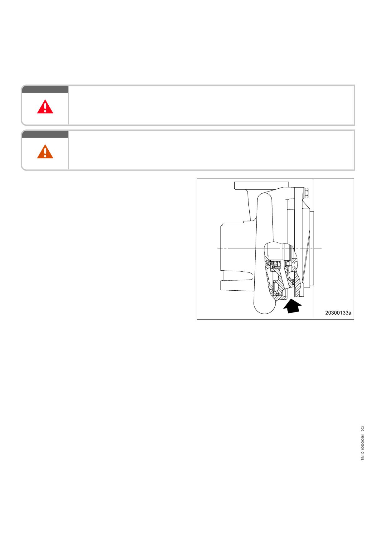
7.16.6
Charge-air coolant pump - Relief bore check
DANGER
Unguarded rotating and moving engine components.
Risk of serious injury - danger to life!
• Take special care when working on a running engine.
WARNING
Engine noise above 85 dB (A).
Risk of damage to hearing!
• Wear ear protectors.
Charge-air coolant pump - Relief
bore check
1.
Check relief bore for oil and coolant dis-
charge.
2.
Stop engine (→ Page 42) and disable en-
gine start, observe general safety instruc-
tions for maintenance and repair.
3.
Clean the relief bore with a wire if it is dirty.
• Permissible coolant discharge: up to 10
drops per hour.
• Permissible oil discharge: up to 5 drops
per hour.
4.
If discharge exceeds the specified limits:
Contact Service.
120 | Task Description | MS150064/01E 2011-11
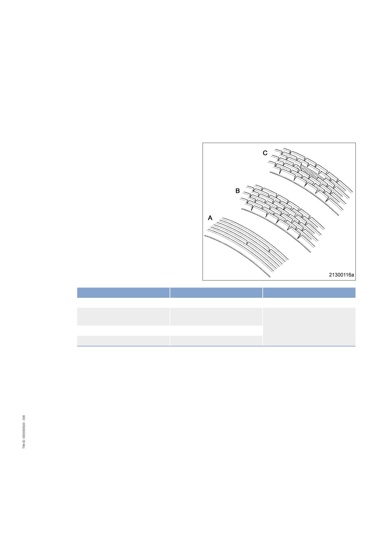
7.17
Belt Drive
7.17.1
Drive belt - Condition check
Preconditions
☑ Engine is stopped and starting disabled.
☑ Guard is removed.
Drive belt - Condition check
Item
Findings
Action
Drive belt A
Singular cracks
None
Drive belt
Belt is oily, shows signs of over-
Replace(→ Page 124)
heating
Drive belt B
Cracks on entire circumference
Drive belt C
Chunking
MS150064/01E 2011-11 | Task Description | 121
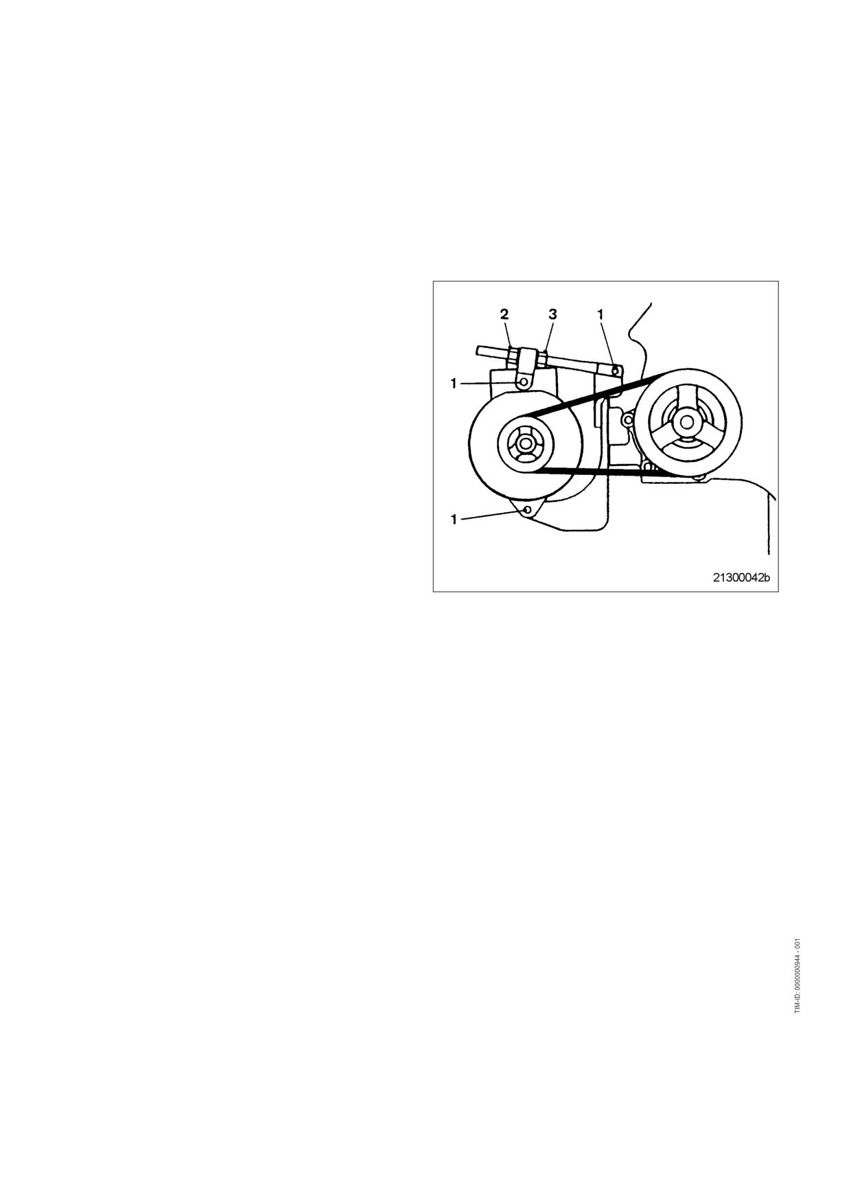
7.18
Battery-Charging Generator
7.18.1
Battery-charging generator drive - Drive belt tension adjustment
Preconditions
☑ Engine is stopped and starting disabled.
Adjusting belt tension
1.
Loosen locknut (2) and screws (1).
2.
Tension drive belt with tensioning nut (3)
and check belt tension (→ Page 123).
3.
Tighten locknut (2).
4.
Tighten screws (1).
5.
Install guard cover.
122 | Task Description | MS150064/01E 2011-11
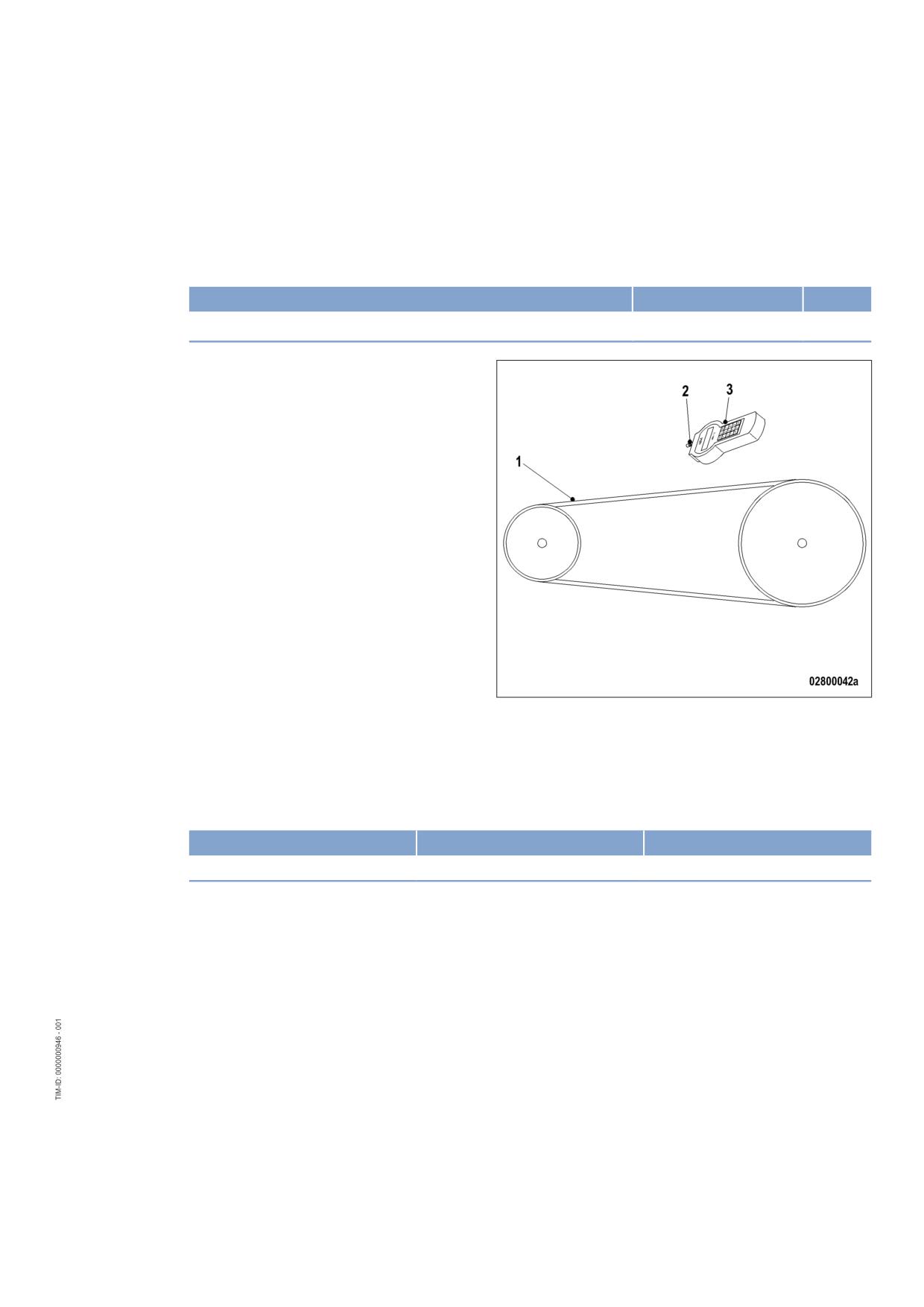
7.18.2
Battery-charging generator drive - Drive belt tension check
Preconditions
☑ Engine is stopped and starting disabled.
Special tools, Material, Spare parts
Designation / Use
Part No.
Qty.
Belt tension tester
Y4345711
1
Preparatory steps
1.
Remove guard cover.
2.
Check belt condition visually (→ Page 121).
Checking drive belt tension
1.
Fit measuring head (2) on belt-tension tester (3) and hit drive belt (1) with a suitable tool.
2.
Hold belt tension tester over belt drive until the measured value is displayed. For specifications, refer to
table below.
Application
Value for new drive belt
Value for used drive belt
Series 4000
92 Hz to 96 Hz
80 Hz to 84 Hz
3.
If the measured values deviate from the specifications above, adjust drive belt tension (→ Page 122).
MS150064/01E 2011-11 | Task Description | 123
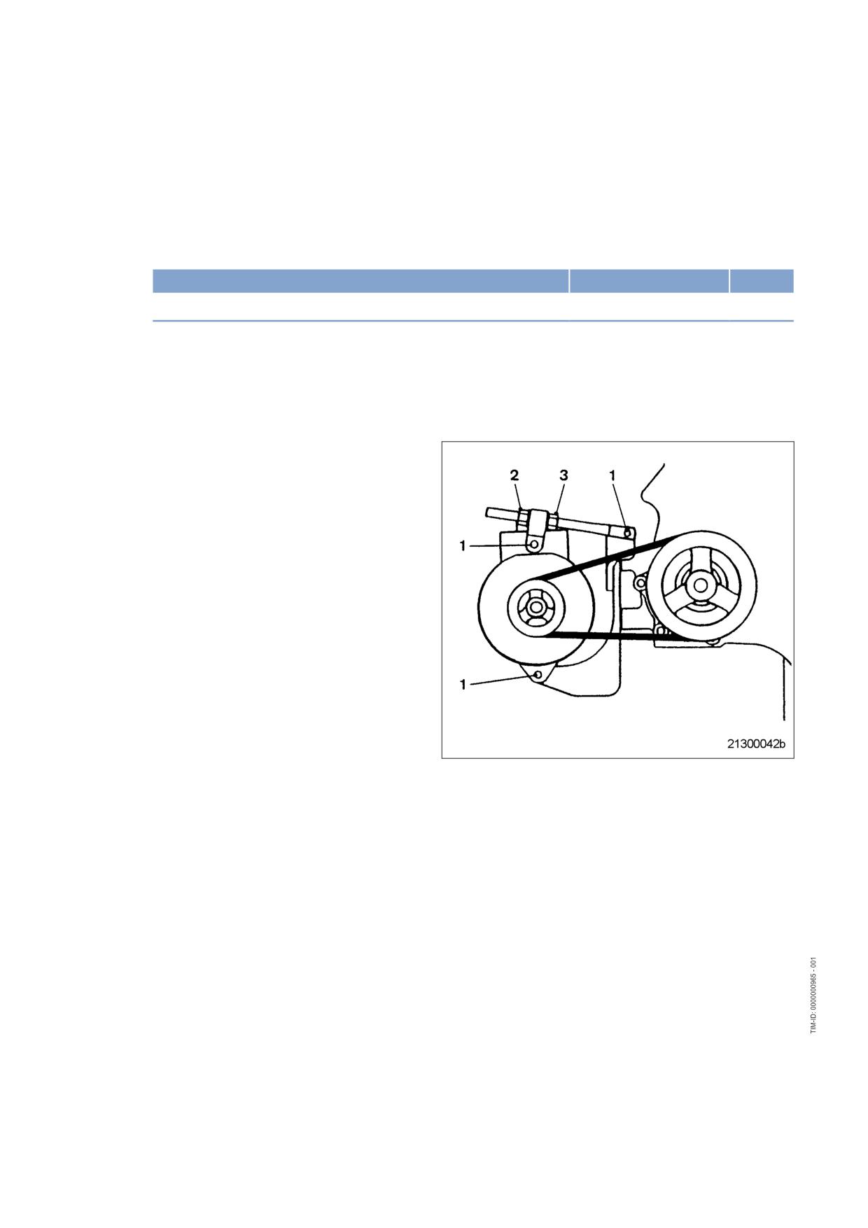
7.18.3
Battery-charging generator drive - Drive belt replacement
Preconditions
☑ Engine is stopped and starting disabled.
Special tools, Material, Spare parts
Designation / Use
Part No.
Qty.
Drive belt
(→ Spare Parts Catalog)
Note:
In the event of drive belt failure during engine operation fit a new drive belt as quickly as possible. Non-
compliance with these instructions may lead to severe consequential damage to drive unit and gear train,
since pretension by the drive belt is no longer provided. Therefore, engine operation without drive-belt
connection is not allowed.
Battery-charging generator drive -
Drive belt replacement
1.
Remove guard cover.
2.
Loosen locknut (2) and screws (1).
3.
Release drive belt with tensioning nut (3)
and take off belt.
4.
Clean belt pulleys.
5.
Fit new drive belt.
6.
Tension drive belt with tensioning nut (3)
and check belt tension (→ Page 122).
7.
Tighten locknut (2).
8.
Tighten screws (1).
9.
Install guard cover.
10.
Check belt tension after 30 minutes and
again after 8 hours engine runtime.
124 | Task Description | MS150064/01E 2011-11
7.19
Wiring (General) for Engine/Gearbox/Unit
7.19.1
Engine wiring - Check
Preconditions
☑ Engine is stopped and starting disabled.
Special tools, Material, Spare parts
Designation / Use
Part No.
Qty.
Isopropyl alcohol
X00058037
1
Engine wiring - Check
1.
Check securing screws of cable clamps on engine and tighten loose threaded connections.
2.
Ensure that cables are fixed in their clamps and cannot swing freely.
3.
Check that cable ties are firm, tighten loose cable ties.
4.
Replace faulty cable ties.
5.
Visually inspect the following electrical line components for damage:
• connector housings;
• contacts;
• sockets;
• cables and terminals;
• plug-in contacts.
6.
(→ Contact Service) if cable conductors are damaged.
Note:
Close male connectors that are not plugged in with the protective cap supplied.
7.
Clean dirty connector housings, sockets and contacts with isopropyl alcohol.
8.
Ensure that all sensor connectors are securely engaged.
MS150064/01E 2011-11 | Task Description | 125
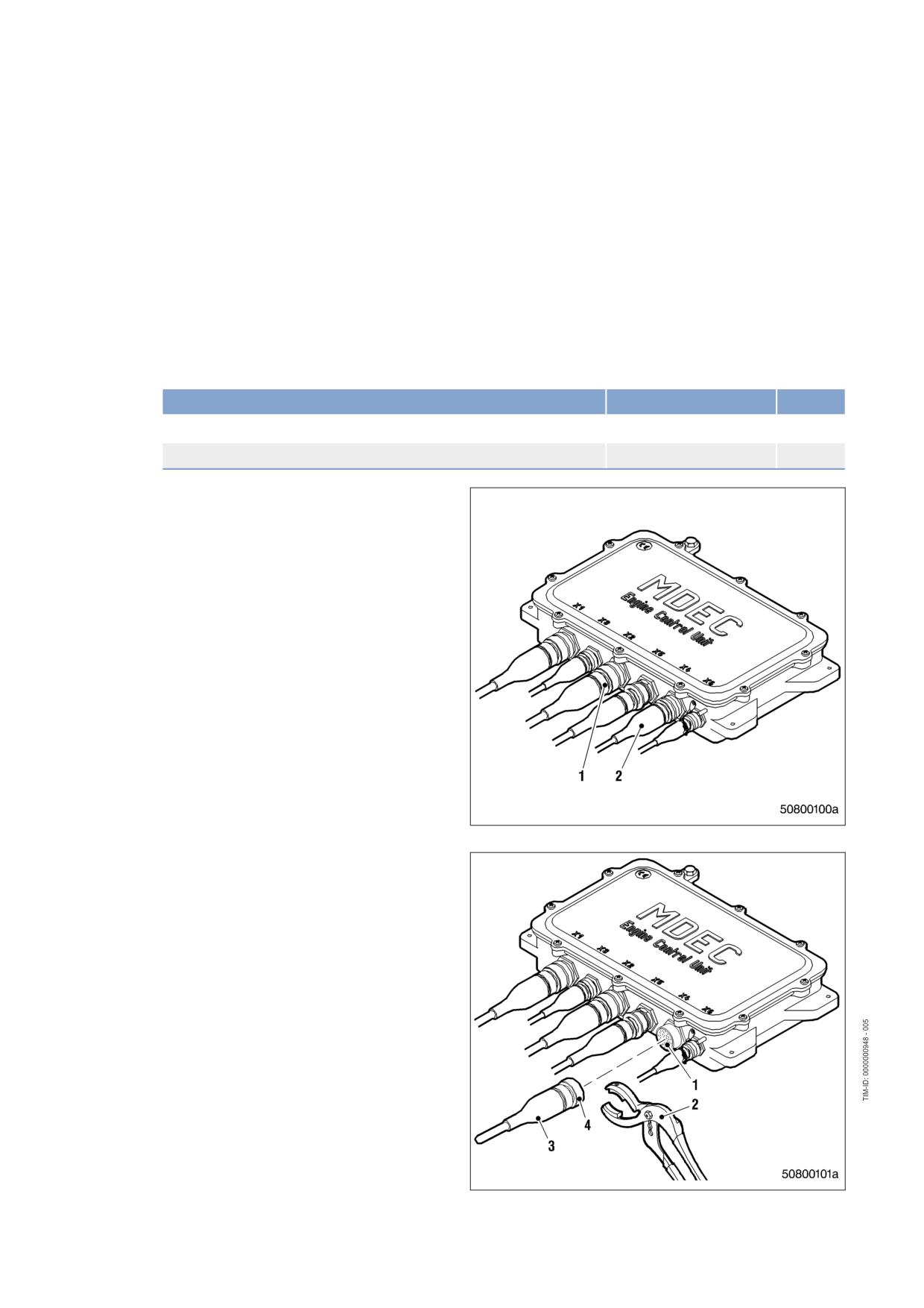
7.20
Accessories for (Electronic) Engine Governor / Control
System
7.20.1
Engine control unit and connectors - Cleaning
Preconditions
☑ Engine shut down and starting disabled.
Special tools, Material, Spare parts
Designation / Use
Part No.
Qty.
Connector pliers
0135315483
1
Isopropyl alcohol
46181
1
Cleaning engine control unit and
connectors
1.
Remove heavy soiling from housing surface
with isopropyl alcohol.
2.
Remove dirt from surface of connectors (1),
connector sockets and shrink-formed com-
ponents (2) using a cloth moistened with
isopropyl alcohol.
3.
Check legibility of cable labels. Clean or re-
place illegible labels.
Cleaning heavily soiled connectors
on engine control unit
1.
Use connector pliers (2) to disengage bayo-
net union nut (4) and withdraw connector
(3).
2.
Clean connector housings, connector sock-
et housings (1) and all contacts with iso-
propyl alcohol.
3.
When connectors, sockets and all contacts
are dry: Fit connectors and check engine
control unit plug connections (→ Page 127).
126 | Task Description | MS150064/01E 2011-11
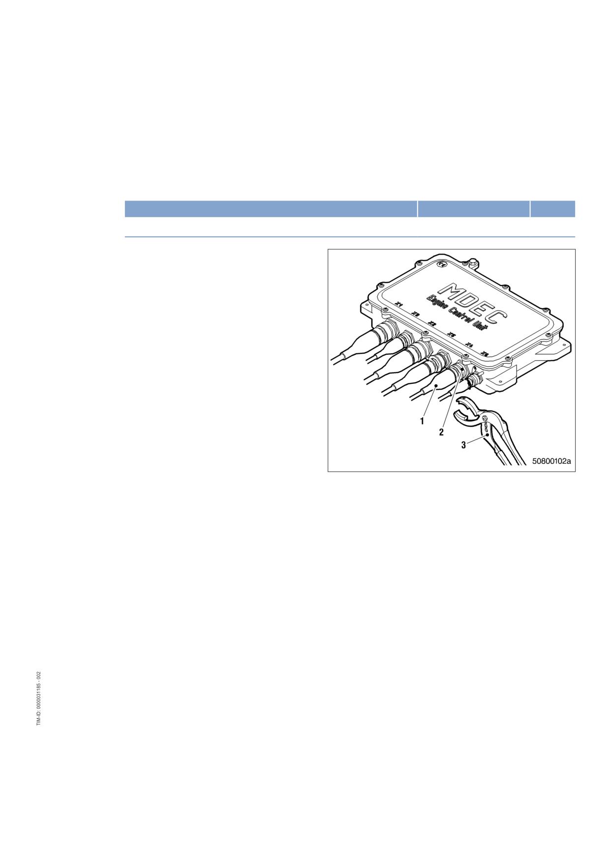
7.20.2
Engine control unit plug connections - Check
Preconditions
☑ Engine shut down and starting disabled.
Special tools, Material, Spare parts
Designation / Use
Part No.
Qty.
Connector pliers
0135315483
1
Checking engine control unit plug
connections
1.
Use connector pliers (3) to make certain
that all plug connections on engine control
unit are securely seated.
2.
Tighten loose bayonet union nuts (2) with
connector pliers (3) by turning them clock-
wise until they latch into place.
3.
Make sure that unassigned sockets are
closed off with cover caps.
4.
If bayonet union nuts are defective, contact
Service.
MS150064/01E 2011-11 | Task Description | 127
8 Appendix A
8.1
Abbreviations
Abbreviation
Meaning
Explanation
A/D
Analog/Digital
Transformer: transforms sensor voltages into
numeric values
ADEC
Advanced Diesel Engine Controller
Engine management system
AFRS
Air Filter Restriction Sensor
ANSI
American National Standards Institute
Association of American standardization or-
ganizations
ATL
Abgasturbolader
Exhaust turbocharger (ETC)
ATS
Air Temperature Sensor
BR
Baureihe
Series
BV
Betriebsstoffvorschrift
MTU Fluids and Lubricants Specifications,
Publication No. A01061/..
CAN
Controller Area Network
Data bus system, bus standard
CDC
Calibration Drift Compensation
Setting of drift compensation in engine gov-
ernor with DiaSys
CEL
Stop Engine Light
1st function: Warning lamp (rectify fault as
soon as possible)
2nd function: Read out fault codes
CKT
Circuit
CLS
Coolant Level Sensor
Monitors coolant level
CPS
Coolant Pressure Sensor
Monitors coolant pressure
CTS
Coolant Temperature Sensor
Monitors coolant temperature
DDEC
Detroit Diesel Electronic Controls
Engine control system made by Detroit Die-
sel
DDL
Diagnostic Data Link
Diagnostic lines
DDR
Diagnostic Data Reader
Diagnostic unit
DIN
Deutsches Institut für Normung e. V.
At the same time identifier of German stand-
ards (DIN = “Deutsche Industrie-Norm”)
DL
Default Lost
Alarm: Default CAN bus failure
DOC
Diesel Oxidation Catalyst
Oxidation catalyst upstream of the diesel
particulate filter
DPF
Diesel Particulate Filter
DT
Diagnostic Tool
Diagnostic unit
ECM
Electronic Control Module
Electronic control unit of the DDEC system
ECU
Engine Control Unit
Engine governor
EDM
Engine Data Module
Memory module for engine data
EEPROM
Electrically Erasable Programmable
Read Only Memory
EFPA
Electronic Foot Pedal Assembly
128 | Appendix A | MS150064/01E 2011-11
Abbreviation
Meaning
Explanation
EGR
Exhaust Gas Recirculation
EMU
Engine Monitoring Unit
ETK
Ersatzteilkatalog
Spare Parts Catalog (SPC)
EUI
Electronic Unit Injector
FPS
Fuel Pressure Sensor
Monitors fuel pressure
FRS
Fuel - Differential Pressure Sensor
FTS
Fuel Temperature Sensor
Monitors fuel temperature
FWCP
Fire Water Control Panel
Control cabinet
GND
Ground
HD
Hochdruck
High Pressure (HP)
HI
High
Alarm: Measured value exceeds 1st maxi-
mum limit
HIHI
High High
Alarm: Measured value exceeds 2nd maxi-
mum limit value
HT
High Temperature
IDM
Interface Data Module
Memory module for interface data
INJ
Injector
ISO
International Organization for Stand-
International umbrella organization for all na-
ardization
tional standardization institutes
KGS
Kraftgegenseite
Engine free end in accordance with DIN ISO
1204
KS
Kraftseite
Engine driving end in accordance with DIN
ISO 1204
LED
Light Emitting Diode
LO
Low
Alarm: Measured value lower than 1st mini-
mum limit value
LOLO
Low Low
Alarm: Measured value lower than 2nd mini-
mum limit value
LSG
Limiting Speed Governor
N/A
Not Applicable
LP
Low Pressure
OEM
Original Equipment Manufacturer
OI
Optimized Idle
OLS
Oil Level Sensor
Monitors oil level
OPS
Oil Pressure Sensor
Monitors oil pressure
OTS
Oil Temperature Sensor
Monitors oil temperature
OT
Oberer Totpunkt
Top Dead Center (TDC)
PAN
Panel
Control panel
PIM
Peripheral Interface Module
PWM
Modulated signal
P-xyz
Pressure-xyz
Pressure measuring point, xyz specifies the
measuring point designation
RL
Redundancy Lost
Alarm: Redundant CAN bus failure
MS150064/01E 2011-11 | Appendix A | 129
Abbreviation
Meaning
Explanation
SAE
Society of Automotive Engineers
U.S. standardization organization
SD
Sensor Defect
Alarm: Sensor failure
SEL
Stop Engine Light
1st function: Warning lamp (stop engine and
rectify fault)
2nd function: Read out fault codes
SID
System Identifier
SRS
Synchronous Reference Sensor
TDC cylinder 1
SS
Safety System
Safety system alarm
TBS
Turbocharger Boost Sensor
Monitors charge-air pressure
TCI
Turbo Compressor Inlet
TCO
Turbo Compressor Outlet
TD
Transmitter Deviation
Alarm: Deviation in transmitter values
TPS
Throttle Position Sensor
TRS
Timing Reference Sensor
T-xyz
Temperature-xyz
Temperature measuring point, xyz specifies
the measuring point designation
UT
Unterer Totpunkt
Bottom Dead Center (BDC)
VNT
Variable Nozzle Turbine
VSG
Variable-Speed Governor
VSS
Vehicle Speed Sensor
WZK
Werkzeugkatalog
Tool Catalog (TC)
130 | Appendix A | MS150064/01E 2011-11
8.2
MTU contacts/service partners
Service
Our worldwide sales network with its subsidiaries, sales offices, representatives and customer service
centers ensures fast and direct support on site and the high availability of our products.
Local support
Experienced and qualified specialists place their knowledge and expertise at your disposal.
For locally available support, go to the MTU internet site: http://www.mtu-online.com
24h hotline
With our 24h hotline and the outstanding flexibility of our service staff, we are always ready to assist you
- either during operation, for preventive maintenance, corrective work in case of malfunction or changed
operating conditions, or for spare parts supply.
Your contact at Headquarters:Service-support@mtu-online.com
Spare parts service
Fast, simple and correct identification of spare parts for your drive system or vehicle fleet. The right spare
part at the right time at the right place.
With this aim in mind, we can call on a globally networked spares logistics system
- a central depot at Headquarters, as well as decentralized depots among our subsidiaries, representa-
tives and contractual workshops.
Your contact at Headquarters:
E-mail: spare.parts@mtu-online.com
Phone: +49 7541 908555
Fax: +49 7541 908121
MS150064/01E 2011-11 | Appendix A | 131
9 Appendix B
9.1
Special Tools
Allen key
Part No.:
F30002817
Qty.:
1
Used in:
7.4.2 Valve clearance - Check and adjustment (→ Page 73)
Barring device
Part No.:
F6555766
Qty.:
1
Used in:
7.1.1 Engine - Barring manually (→ Page 63)
Belt tension tester
Part No.:
Y4345711
Qty.:
1
Used in:
7.18.2 Battery-charging generator drive - Drive belt tension check (→ Page 123)
Connector pliers
Part No.:
0135315483
Qty.:
1
Used in:
7.1.2 Engine - Barring with starting system (→ Page 64)
Qty.:
1
Used in:
7.20.1 Engine control unit and connectors - Cleaning (→ Page 126)
Qty.:
1
Used in:
7.20.2 Engine control unit plug connections - Check (→ Page 127)
Feeler gauge
Part No.:
Y20010128
Qty.:
1
Used in:
7.4.2 Valve clearance - Check and adjustment (→ Page 73)
Filter wrench
Part No.:
F30379104
Qty.:
1
Used in:
7.8.1 Fuel filter - Replacement (→ Page 84)
Qty.:
Used in:
7.14.1 Engine oil filter - Replacement (→ Page 102)
Qty.:
1
Used in:
7.14.2 Centrifugal oil filter - Cleaning and filter sleeve replacement (→ Page 103)
Installation and removal tool for injector
Part No.:
F6790161
Qty.:
1
Used in:
7.6.2 Injector - Removal and installation (→ Page 78)
132 | Appendix B | MS150064/01E 2011-11
Milling cutter
Part No.:
F30452739
Qty.:
1
Used in:
7.6.2 Injector - Removal and installation (→ Page 78)
MTU test kit
Part No.:
5605892099/00
Qty.:
1
Used in:
7.13.3 Engine oil - Sample extraction and analysis (→ Page 101)
Qty.:
1
Used in:
7.15.6 Coolant - Sample extraction and analysis (→ Page 112)
MTU test kit
Part No.:
Qty.:
Used in:
7.16.5 Charge-air coolant - Sample extraction and analysis (→ Page 119)
Ratchet adapter
Part No.:
F30027340
Qty.:
1
Used in:
7.3.1 Crankcase breather - Oil separator replacement, diaphragm check and replace-
ment (→ Page 70)
Ratchet adapter
Part No.:
F30027341
Qty.:
1
Used in:
7.13.2 Engine oil - Change (→ Page 99)
Ratchet adapter
Part No.:
F30027339
Qty.:
1
Used in:
7.14.2 Centrifugal oil filter - Cleaning and filter sleeve replacement (→ Page 103)
Ratchet with extension
Part No.:
F30006212
Qty.:
1
Used in:
7.1.1 Engine - Barring manually (→ Page 63)
Rigid endoscope
Part No.:
Y20097353
Qty.:
1
Used in:
7.2.1 Cylinder liner - Endoscopic examination (→ Page 66)
Slotted nut screwdriver
Part No.:
F30452578
Qty.:
1
Used in:
7.6.2 Injector - Removal and installation (→ Page 78)
MS150064/01E 2011-11 | Appendix B | 133
Socket wrench, 24 mm
Part No.:
F30039526
Qty.:
1
Used in:
7.4.2 Valve clearance - Check and adjustment (→ Page 73)
Steam jet cleaner
Part No.:
-
Qty.:
1
Used in:
4.10 Plant - Cleaning (→ Page 46)
Torque wrench, 0.5-5 Nm
Part No.:
0015384230
Qty.:
1
Used in:
7.6.2 Injector - Removal and installation (→ Page 78)
Torque wrench, 10-60 Nm
Part No.:
F30510423
Qty.:
1
Used in:
1.4 Crankshaft transport locking device (→ Page 10)
Qty.:
1
Used in:
7.6.2 Injector - Removal and installation (→ Page 78)
Torque wrench, 40-200 Nm
Part No.:
F30027337
Qty.:
1
Used in:
7.13.2 Engine oil - Change (→ Page 99)
Torque wrench, 6-50 Nm
Part No.:
F30027336
Qty.:
1
Used in:
7.3.1 Crankcase breather - Oil separator replacement, diaphragm check and replace-
ment (→ Page 70)
Torque wrench, 6-50 Nm
Part No.:
F30027336
Qty.:
1
Used in:
7.14.2 Centrifugal oil filter - Cleaning and filter sleeve replacement (→ Page 103)
Torque wrench, 60-320 Nm
Part No.:
F30047446
Qty.:
1
Used in:
1.4 Crankshaft transport locking device (→ Page 10)
Qty.:
1
Used in:
7.4.2 Valve clearance - Check and adjustment (→ Page 73)
Qty.:
1
Used in:
7.6.2 Injector - Removal and installation (→ Page 78)
134 | Appendix B | MS150064/01E 2011-11
9.2
Index
12V 4000 engine data, continuous operation, variable
Engine
3B, emissions optimized (TA-Luft) 31
- Barring manually
63
12V 4000 engine data, continuous operation, variable
– Main dimensions
36
3B, emissions optimized w/o certificate 27
– Test run
65
12V 4000 engine data, continuous operation, variable
– Wiring check
125
3B, optimized fuel consumption 23
Engine control unit
- plug connections check
127
A
Engine control unit and connectors
Abbreviations 128
- Cleaning
126
After stopping the engine - Engine remains ready for op-
Engine coolant
eration 44
- Change
106
After stopping the engine - putting the engine out of
– Draining
107
service 45
Engine coolant pump
Air filter
- Relief bore check
111
- Removal and installation
94
Engine layout 22
– Replacement
93
Engine oil
Air starter - Manual operation 96
- Change
99
- Sample extraction and analysis
101
C
Engine oil filter
Centrifugal oil filter
- Replacement
102
- Cleaning and filter sleeve replacement
103
Engine oil level
Charge-air coolant
- Check
98
- Change
114
Engine side and cylinder
– Filling
116
- Designations
21
– Level check
113
Engine wiring
Charge-air coolant level
- Check
125
- Check
113
Charge-air coolant pump
F
- Relief bore check
120
Fault messages on engine governor 51
Contacts 131
Final compression pressure 34
Contamination indicator
Fire prevention and environmental protection 18
- Signal ring position check
95
Firing order 35
Coolant
Fluids and lubricants 18
- Sample extraction and analysis
112
Fuel
Coolant - charge air
- prefilter
- Level check
113
- Flushing
88
Coolant - charge-air
Fuel filter
- Change
114
- Replacement
84
Coolant level
Fuel prefilter
- Check
105
- Differential pressure gauge
Crankshaft transport locking device
- Check and adjustment
86
- Removal/installation
10
– Draining
87
Cylinder head cover
– Filter element
- Removal and installation
75
- Replacement
90
Cylinder liner
– Flushing
88
- Endoscopic examination
66
Fuel prefilter cleaning 85
– Instructions and comments on endoscopic and visual
G
examination
68
General conditions 7
D
Drive belt
H
- Condition check
121
HP pump
- Relief bore check
76
E
Emergency stop 43
MS150064/01E 2011-11 | Appendix B | 135
I
Injector
- Removal and installation
78
– Replacement
77
Inspection port cover
- Explosion hazard
14
Intercooler
- Drain, coolant leakage
92
M
Maintenance and repair work
- Safety regulations
15
MTU contact persons 131
O
Operational checks 41
P
Personnel and organizational requirements 8
Plant
- Cleaning
46
Putting the engine into operation after extended out-of-
service periods (>3 months) 37
Putting the engine into operation after scheduled out-of-
service-period 38
S
Safety instructions 20
Service partners 131
Start engine in manual mode (testing mode) 39
Starter
- Condition check
97
Starting the engine in emergency situations (override
mode) 40
Startup and operation
- Safety regulations
13
Stop engine in manual mode (testing mode) 42
T
Transport 9
Troubleshooting 48
V
Valve clearance
- Check and adjustment
73
Valve gear
- Lubrication
72
W
Wiring - engine
- Check
125
136 | Appendix B | MS150064/01E 2011-11