HANGCHA CPD10 / CPD40 (1~5t J Series Counterbalanced Battery Forklift Truck). SERVICE MANUAL (2010)
CPD10/15/18/20/25/30J
CPD10/15/18/20/25/30J D1
CPD10/15/18/20/25/30/35J C1
CPD10/15/18/20/25/30/35J C2
CPD40/45/50J D1
CPD40/45/50J C2
1~5t J Series Counterbalanced Battery Forklift Truck
SERVICE MANUAL
Original Instruction
HANGCHA GROUP CO., LTD.
Dec. 2010 3rd edition
FOREWORD
Thanks for your purchasing our forklift truck.
4 wheel counterbalanced battery forklift truck is our company’s new product. It has the character
of small turning radius, beautiful shape, small dimensions, low gravity.
This operation manual is the explanations that how to use 1-3tJ series forklift truck correctly. It
will instruct you how to operate safety and precautionary maintenance.
To ensure safety and exert the truck’s potential, all the personnel that in charge of operation,
maintenance and management must read this manual thoroughly before starting work with the forklift.
This manual is applicable to container trucks.
Forbid repairing the truck if you haven’t been trained.
Our product design will update and perform better, so the content in this manual may
be not the same as the forklift you owned.
If you have any questions please keep touches with HANGCHA GROUP CO.,LTD.sales
department or let the agents know.
The meanings of model
Tow electric
Rise electric
Rated capacity(t)/
Truck model
control
control
load centre distance(mm)
1244
1254
CPD10/15/18/20/25/30J
1.0/500,1.5/500,1.8/500,
(CURTIS)
(CURTIS)
2.0/500,2.5/500,3/500,
ACS
ACS
CPD10/15/18/20/25/30J D1
4/500,4.5/500,5/500
(INMOTION)
(INMOTION)
1238
EVC255
1.0/500,1.5/500,1.8/500,
CPD10/15/18/20/25/30/35J C1
(CURTIS)
(CURTIS)
2.0/500,2.5/500,3/500,3.5/300
1238
1236
1.0/500,1.5/500,1.8/500,
CPD10/15/18/20/25/30/35J C2
(CURTIS)
(CURTIS)
2.0/500,2.5/500,3/500,3.5/300
1238
1238
CPD40/45/50J C2
4/500,4.5/500,5/500
(CURTIS)
(CURTIS)
© Dec. 2010 3rd edition HANGCHA GROUP CO., LTD.
CONTENT
FOREWORD
1. DRIVING SYSTEM
1
1.1 ENGINE FOR FORKLIFT
1
1.2 GEAR BOX
8
1.3 DRIVING AXLE
9
2. STEERING SYSTEM
14
2.1 STEERING DEVICE
14
2.2 STEERING AXLE
15
3. BRAKE SYSTEM
19
3.1 MASTER CYLINDER
19
3.2 FOOT BRAKE
20
3.3 HAND BRAKE DEVICE
22
4. HYDRAULIC SYSTEM
23
5. LIFTING SYSTEM
27
5.1 DATA
27
5.2 FAULT
28
5.3 MAST
30
5.4 LIFTING CYLINDER
32
5.5 TILTING CYLINDER
32
6. ELECTRICAL SYSTEM
33
6.1 CPD10/15/20/25/30J FORK
33
6.2 CPD10/15/20/25/30/35J C1、CPD10/15/18/20/25/30/35J C2、CPD40/45/50J C2 FORK
37
6.3 CPD10/15/20/25/30J D1 FORK
44
7. MAINTENANCE RECORD
57

1. Driving system
Drive system is composed most components such as electrical engineering, gear box, driving axle
detent tyre and wheel rim.
Gear box is two grades reduce speed gear, one grade straight gear and one grade planet gear. So the
gear box is very small.
Detent is a hoof detent, if you need know the particular content, you can see relevant portion of the
trig system.
1.1 Engine for Forklift
1.1.1Data
CPD10/15J/18J
Rated
Rated
Rated
Rated
Max.
Excitations
Insulation
Cooling
Protecting
Ration
Weight
Model
Power
Voltage
Current
speed
Speed
Remark
Mode
Grade
Mode
Grade
(m)
(Kg)
( kw)
(V)
(A)
(r/m)
(r/m)
separate
XQ - 5-3A
5.3
45
139
1700
3200
F
IC01
IP20
60
95
tow
excitation
series
XQD -8.2-3D
8.2
45
172.8
1600
3200
F
IC01
IP20
5
65
work
excitation
CPD20/25J
Rated
Rated
Rated
Rated
Max.
Excitations
Insulation
Cooling
Protecting
Ration
Weight
Model
Power
Voltage
Current
speed
Speed
Remark
Mode
Grade
Mode
Grade
(m)
(Kg)
( kw)
(V)
(A)
(r/m)
(r/m)
separate
XQ-7A
7
45
180
1200
2400
F
IC01
IP20
60
112
tow
excitation
series
XQD-8.6-3D
8.6
45
248
1600
3200
F
IC00
IP44
5
72
work
excitation
CPD30J
Rated
Rated
Rated
Rated
Max.
Excitations
Insulation
Cooling
Protecting
Ration
Weight
Model
Power
Voltage
Current
speed
Speed
Remark
Mode
Grade
Mode
Grade
(m)
(Kg)
( kw)
(V)
(A)
(r/m)
(r/m)
separate
XQ - 10.2 A
10.2
75
162.5
1500
/
F
IC01
IP20
60
120
tow
excitation
series
XQD - 10 -3D
10
75
161.6
2000
/
F
IC01
IP20
15
83
work
excitation
1

CPD10/15/18J C1
Rated
Rated
Rated
Rated
Max.
Excitations
Insulation
Cooling
Protecting
Ration
Weight
Model
Power
Voltage
Current
speed
Speed
Remark
Mode
Grade
Mode
Grade
(m)
(Kg)
( kw)
(V)
(A)
(r/m)
(r/m)
YDQ6.8-4HC
6.8
31
222
1200
2000
AC
F
IC01
IP20
60
94
tow
series
XQD -8.2-3D
8.2
45
172.8
1600
3200
F
IC01
IP20
5
65
work
excitation
CPD20/25J C1
Rated
Rated
Rated
Rated
Max.
Excitations
Insulation
Cooling
Protecting
Ration
Weight
Model
Power
Voltage
Current
speed
Speed
Remark
Mode
Grade
Mode
Grade
(m)
(Kg)
( kw)
(V)
(A)
(r/m)
(r/m)
YDQ9.1-4HC
9.1
31
280
1200
2000
AC
F
IC01
IP20
60
110
tow
series
XQD-8.6-3D
8.6
45
248
1600
3200
F
IC00
IP44
5
72
work
excitation
CPD30/35J C1
Rated
Rated
Rated
Rated
Max.
Excitations
Insulation
Cooling
Protecting
Ration
Weight
Model
Power
Voltage
Current
speed
Speed
Remark
Mode
Grade
Mode
Grade
(m)
(Kg)
( kw)
(V)
(A)
(r/m)
(r/m)
YDQ11.75-4HC
10.6
51
180
1200
/
AC
F
IC01
IP20
60
110
tow
series
XQD - 10 -3D
10
75
161.6
2000
/
F
IC01
IP20
15
83
work
excitation
CPD10/15/18J C2
Rated
Rated
Rated
Rated
Max.
Excitations
Insulation
Cooling
Protecting
Ration
Weight
Model
Power
Voltage
Current
speed
Speed
Remark
Mode
Grade
Mode
Grade
(m)
(Kg)
( kw)
(V)
(A)
(r/m)
(r/m)
YDQ6.8-4HC
6.8
31
222
1200
2000
AC
F
IC01
IP20
60
94
tow
YDQ-8.6
8.6
31
248
1600
3200
AC
F
IC01
IP44
5
65
work
CPD20/25J C2
Rated
Rated
Rated
Rated
Max.
Excitations
Insulation
Cooling
Protecting
Ration
Weight
Model
Power
Voltage
Current
speed
Speed
Remark
Mode
Grade
Mode
Grade
(m)
(Kg)
( kw)
(V)
(A)
(r/m)
(r/m)
YDQ9.1-4HC
9.1
31
280
1200
2000
AC
F
IC01
IP20
60
110
tow
YDQ-8.6HC
8.6
31
248
1600
3200
AC
F
IC00
IP44
5
65
work
2

CPD30/35J C2
Rated
Rated
Rated
Rated
Max.
Excitations
Insulation
Cooling
Protecting
Ration
Weight
Model
Power
Voltage
Current
speed
Speed
Remark
Mode
Grade
Mode
Grade
(m)
(Kg)
( kw)
(V)
(A)
(r/m)
(r/m)
YDQ11.75-4HC
10.6
51
180
1200
/
AC
F
IC01
IP20
60
110
tow
YDQ - 10
10
51
161.6
2000
/
AC
F
IC01
IP44
15
80
work
CPD40/45/50J C2
Rated
Rated
Rated
Rated
Max.
Excitations
Insulation
Cooling
Protecting
Ration
Weight
Model
Power
Voltage
Current
speed
Speed
Remark
Mode
Grade
Mode
Grade
(m)
(Kg)
( kw)
(V)
(A)
(r/m)
(r/m)
YDQ16.6-4HC
16.6
51
250
3100
5000
AC
H
IC00
IP20
60
155
tow
YDB25.4-4
25.4
51
387
1620
3200
AC
H
IC00
IP20
5
115
work
CPD10/15J D1
Rated
Rated
Rated
Rated
Max.
Excitations
Insulation
Cooling
Protecting
Ration
Weight
Model
Power
Voltage
Current
speed
Speed
Remark
Mode
Grade
Mode
Grade
(m)
(Kg)
( kw)
(V)
(A)
(r/m)
(r/m)
TSP180/4-180-48V
10.5
31
280
1200
2000
AC
F
IC01
IP20
60
135
tow
TSW112/4-195-T-48V
11
31
285
2000
3200
AC
F
IC01
IP20
15
83
work
CPD20/25J D1
Rated
Rated
Rated
Rated
Max.
Excitations
Insulation
Cooling
Protecting
Ration
Weight
Model
Power
Voltage
Current
speed
Speed
Remark
Mode
Grade
Mode
Grade
(m)
(Kg)
( kw)
(V)
(A)
(r/m)
(r/m)
TSP180/4-180-48V
10.5
31
280
1200
2000
AC
F
IC01
IP20
60
135
tow
TSW112/4-195-T-48V
11
31
285
2000
3200
AC
F
IC01
IP20
15
83
work
CPD30J D1
Rated
Rated
Rated
Rated
Max.
Excitations
Insulation
Cooling
Protecting
Ration
Weight
Model
Power
Voltage
Current
speed
Speed
Remark
Mode
Grade
Mode
Grade
(m)
(Kg)
( kw)
(V)
(A)
(r/m)
(r/m)
TSP180/4-180-80V
10.6
51
180
1200
2000
AC
F
IC01
IP20
60
135
tow
TSW112/4-195-T-80V
12.8
51
216
2000
3200
AC
F
IC01
IP20
15
83
work
3

CPD40/45/50J-D1
Rated
Rated
Rated
Rated
Max.
Excitations
Insulation
Cooling
Protecting
Ration
Weight
Model
Power
Voltage
Current
speed
Speed
Remark
Mode
Grade
Mode
Grade
(m)
(Kg)
( kw)
(V)
(A)
(r/m)
(r/m)
AC
tow
TSP180/4-200
16.6
52
/
/
/
F
IC01
IP20
60
/
AC
work
TSP160/4-250-T
25
49
387
1620
/
F
IC01
IP20
5
/
Height above sea level
No exceed 1200m
Remark
electromotor
Environment
temperature
400C/-250C
applied range
highest/lowest
Relative temperature
Until on the surface of motor dew 100%
Cooling air
Must not contain volatile gas
Three times of rated current ,admit
most work
Tractor motor
time is one minute
current of the
One point eight times of rated current
motor
Lifting motor、steering motor
,admit time is one minute
Admit temperature Rolling bearing(Environment
temperature not exceed
400C)
950C
From brush box catadrome side to surface of the
JD1
2~4mm
commutation
not
Cooling insulation resistance(When it approach work
< 45V
0.5MΩ
temperature, please measure by 250Vmegohmmeter)
45V~110V
1MΩ
JD1
Brush
Metal plumbagin brush trade J201 chart No 5CZ、578
not
4
1.1.2 Failure diagnosis
CPD10-30
Failure phenomenon
Possible cause
All of sheet copper nigrescence
Brush’s pressure is wrong
Parts of commutator according to
parts is short circuit
a certain order nigrescence
armature coil is short
parts of commutator is not fasten to armature coils open circuit
Parts of commutator are
commutator’s center line location change
nigrescent, but without definite
·commutator’ s surface is rough, out of round
rule
·motor vibration
clearance between brush and box is bigger.
·working surface distance between the box and commutator is
Brush wear and tear, change
bigger
colors and break
·mice between parts of commutator extrude
·material of the brush is bad
trademark of the brush is wrong
·motor overload
commutator is unholy
commutator is rough or out of round
·mica or parts of commutator extrude
brush seat grinding is bad
Sparkle strong
the pressure of brush is not enough big
trademark of the brush is wrong
the brush lock in the box
the brush frame is loose or vibrational
the polarity and tactic order of magnetic pole is wrong
the sparkle of brush is strong
The brush and wire heat
the brush is not contacted with the cable
the cable is thinner
The brush have noise
the surface of the commmutator is rough
5
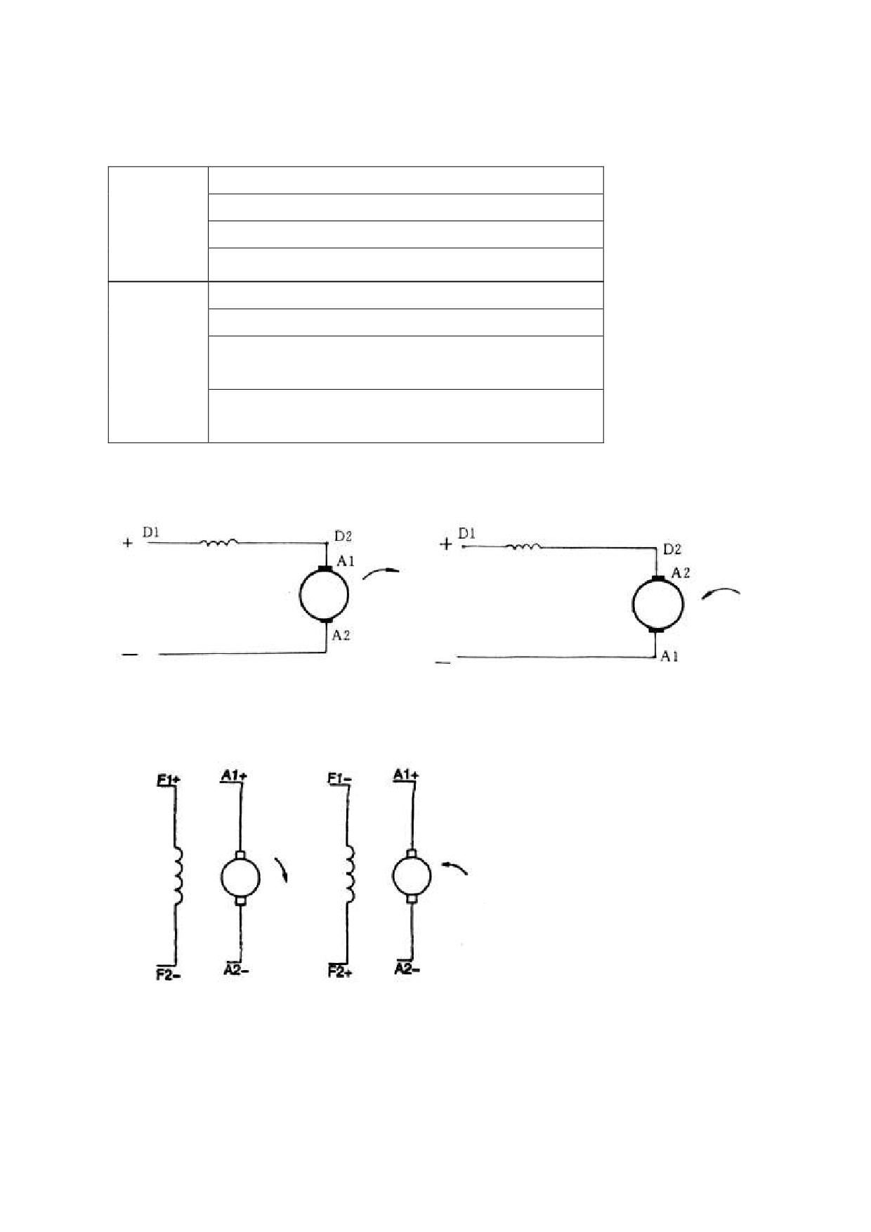
1.1.3The marker, sign and connecting type of exceed cable or terminal of motor
A1 --motor armature's head
series
A2--motor armature's end
excitation
D1--shunt excitation's head
motor
D2--shunt excitation's end
A1 --motor armature's head
A2--motor armature's end
Separated
F1-Separated
Excitation
Excitation excitation's head
motor
F2-- Separated
Excitation excitation's end
Connection mode
Series excitation motor
Separate excitation motor
6
1.1.4 Use and maintain
CPD10-30J
The commutator has four check windows, with which you can observe and maintain the
commutator and brush. There are four average distributing magnetic poles in seat. The magnetic pole
coil is made of F state copper thread, dipping with F state insulating varnish. Parts of stator and neutral
position of brush have been adjusted; users mustn’t unpack and adjust randomly.
·Check armature for rotation and void frictionize.
·Check outgoing line of electric machine for connection
·Brush should slide freely in the brush hold box.
·Check reverse chip for neatness, if need be,clear canaliculus between the reverse chip or the
commutator surface of powder, can used cleanly calico of soft and no thread downy , maybe surface
had oil ,calico can dip alcohol when wiping (stop process).
check all fasteners whether fastened.
·brush’s shelf must reliable fastened, can’t become flexible. If need running or disassembly brush’s
shelf, must make out marker,can become flexible bolt. When the brush’s shelf reposition, aim at
marker line, screw down bolt, in order to keep brush in the former neutral location.
·winding isolating resistance should check of fix a date, when near work’s temperature, under rule data,
otherwise should put up dry.
fix a date open window shutter, check inside part whether transmutation and reverse partial circs
whether up to snuff.
you should often clean bed load and other dirt on the motor’s shell, in order to giving out heat quantity
best.
Every half year check motor one time as follow:
a. Inspect exterior and clean the dust for the motor;
b. Clean or replace bearing, during running it is permitted to giving off abnormal noise for bearing;
c. Inspect the brush’s abrasion, if necessary replace it.
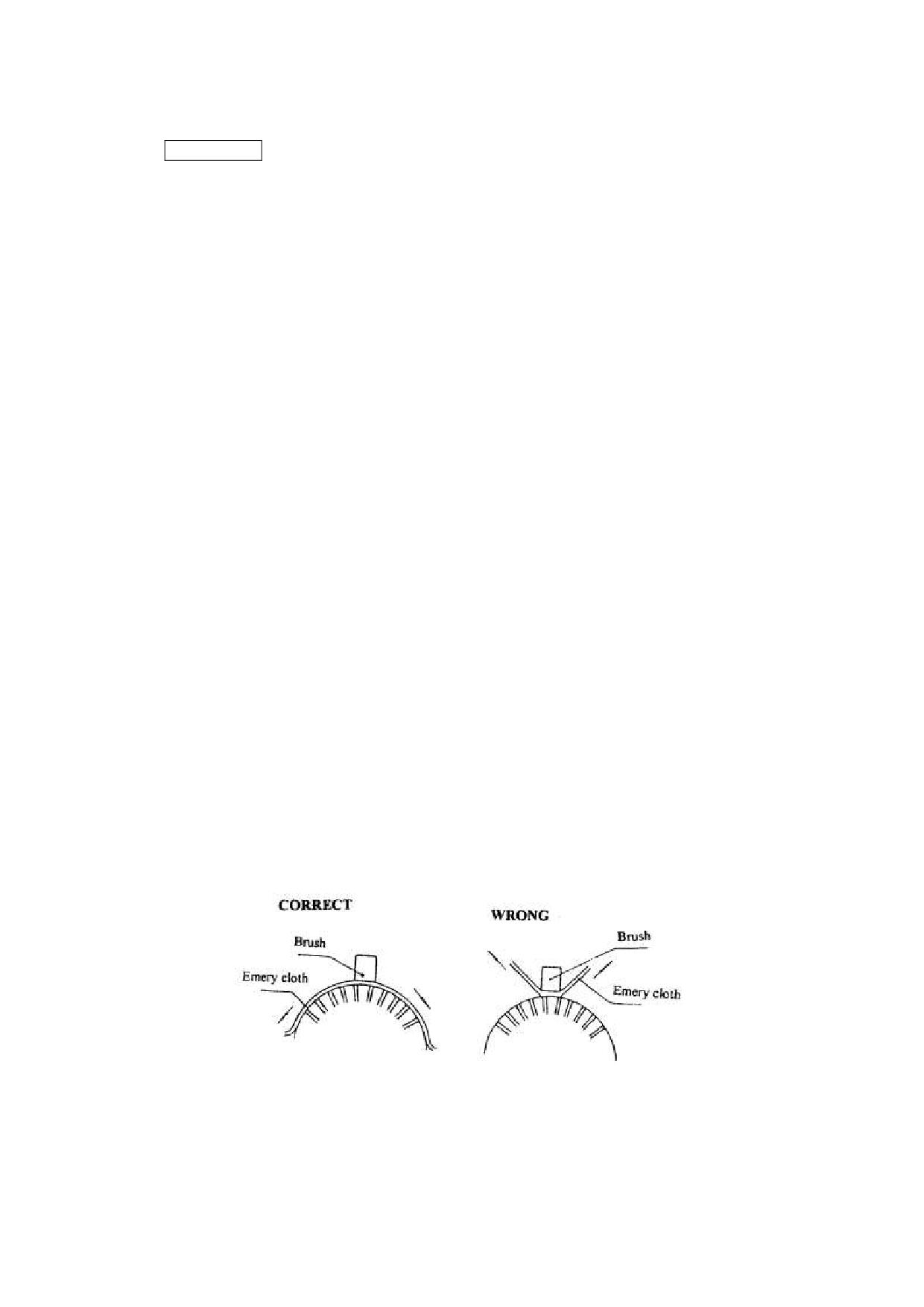
Burnishing for brush:
·When replaces the brush, using ―00‖ thin emery cloth to burnishing it. During burnishing you can haul
the emery cloth leftward or rightward.
·After burnish the brush and clean the commutator with emery cloth, the motor should lowered voltage
and limiting speed to running under load, in order to safety, till the brush’s working face is shined.
7
CPD10/15/18/20/25/30/35J C1
CPD10/15/18/20/25/30/35J C2、CPD40/45/50J C2
CPD10/15/18/20/25/30J D1、CPD40/45/50J D1
CPD10/15/18/20/25/30/35J C1 、 CPD10/15/18/20/25/30/35J C2 、 CPD40/45/50J C2 、
CPD10/15/18/20/25/30J D1、CPD40/45/50J D1 fork don’t have commutator and brush,not need
maintain. You must clear dust everyday.
1.2 Gear box
Gear box is two grades reduce speed gear, one grade straight gear and one grade planet gear. So the
gear box is very small.
Trouble
Probably cause
Method of troubleshooting
When traveling or change
Gear clearance is too big.
Adjust.
direction
Too much worn of gear.
Replace.
Oil level is low.
Add oil.
Too much noise when traveling
Gear clearance is too big.
Adjust.
Too much worn of gear.
Replace.
1. Box
2.Bearing pedestal
3. Bolt
4.Bearing pedestal
5.O joint ring
8.Dual
11. dual articulated
9. Axletree 6206
10.Axletree 6307
12.Axletree 6305
articulated gear
gear
15.Positioning
13.axes
14. O joint ring
16. Bolt
17. Pinion
board
18. Axletree 6208
19. Tank cap
20. Bolt
21. Bolt
23.Pin
8
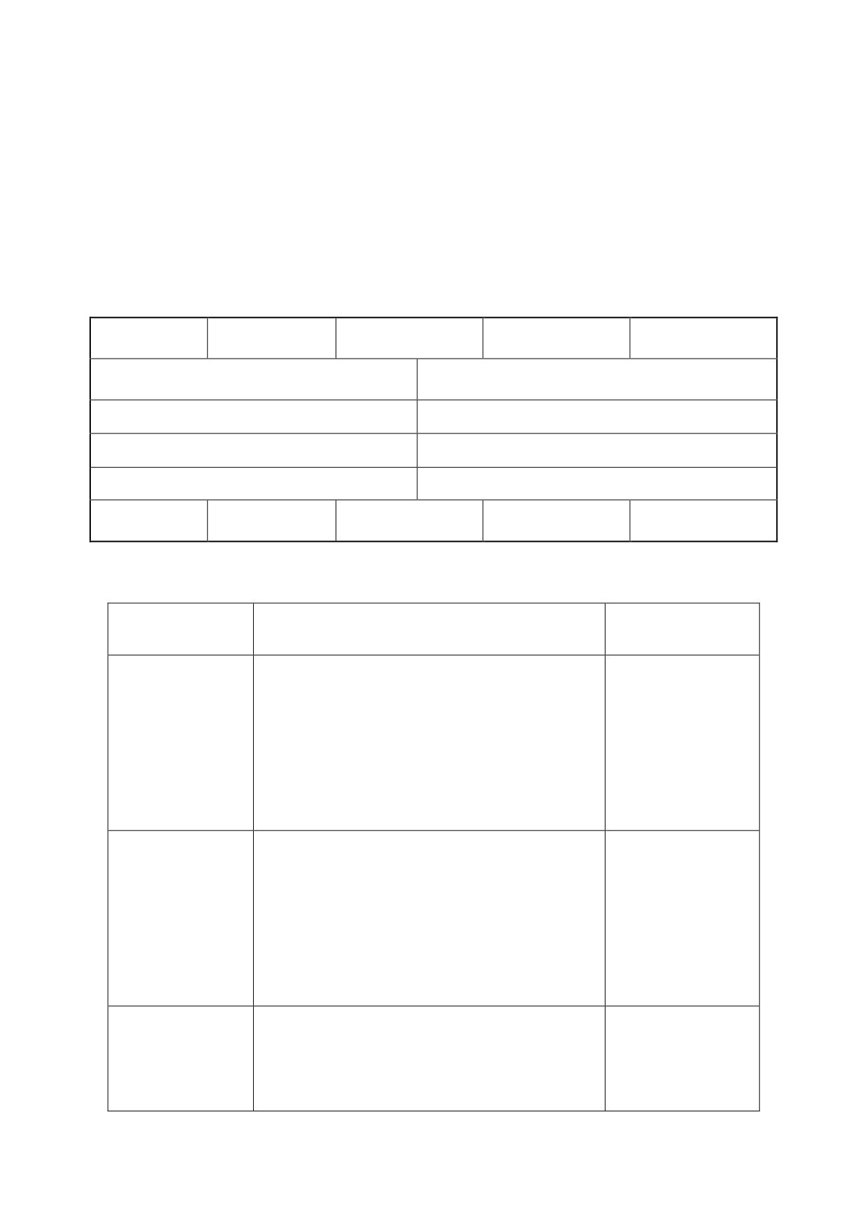
27.right differential
28.left differential
24. Girth gear
25. bolt
26.nut
carrier
carrier
29. Gear shaft (I)
30. Face gear
31. Gasket
32. Planetary gear
33. Thrust washer
34. Axletree 6211
35. Straight pin
36.Gear shaft (II)
37. Paper gasket
38.pin
39. Lock plate
40. Lock washer
1.3 Driving axle
1.3.1 Data
Type
1-1.8t
2-2.5t
3t
4-5t
Full floating, axle and truck body direct install, front
Driving axle type
Tire pressure
10.30MPa
Wheel hub rotation starting torque at hub blot N
10~29
Axial play of wheel bearing mm
less than 0.08
weight
125-130
195-198
202-208
350-380
1.3.2 Trouble diagnoses and corrections
condition
Probable cause
Corrective action
loose driving axle and body connecting blots.
Tighten.
loose wheel nut
Tighten.
·worn or damaged wheel hub bearing.
Replace.
Abnormal noises
·wheel hub bearing not properly adjusted.
Adjust.
·worn axle shaft spliner.
Replace.
insufficient lubrication
Lubricate.
loose wheel nut.
Tighten.
deformed wheel.
Replace.
·worn or damaged wheel hub bearing.
Replace.
Unstable driving
loose driving axle and body connecting blots.
Tighten.
·wheel hub bearing not properly adjusted.
Adjust.
improper tire pressure.
Adjust.
·worn or damaged axle shaft oil seal.
Replace
Oil leakage
final drive improperly installed.
Replace gasket.
loose drain plug.
Tighten.
9
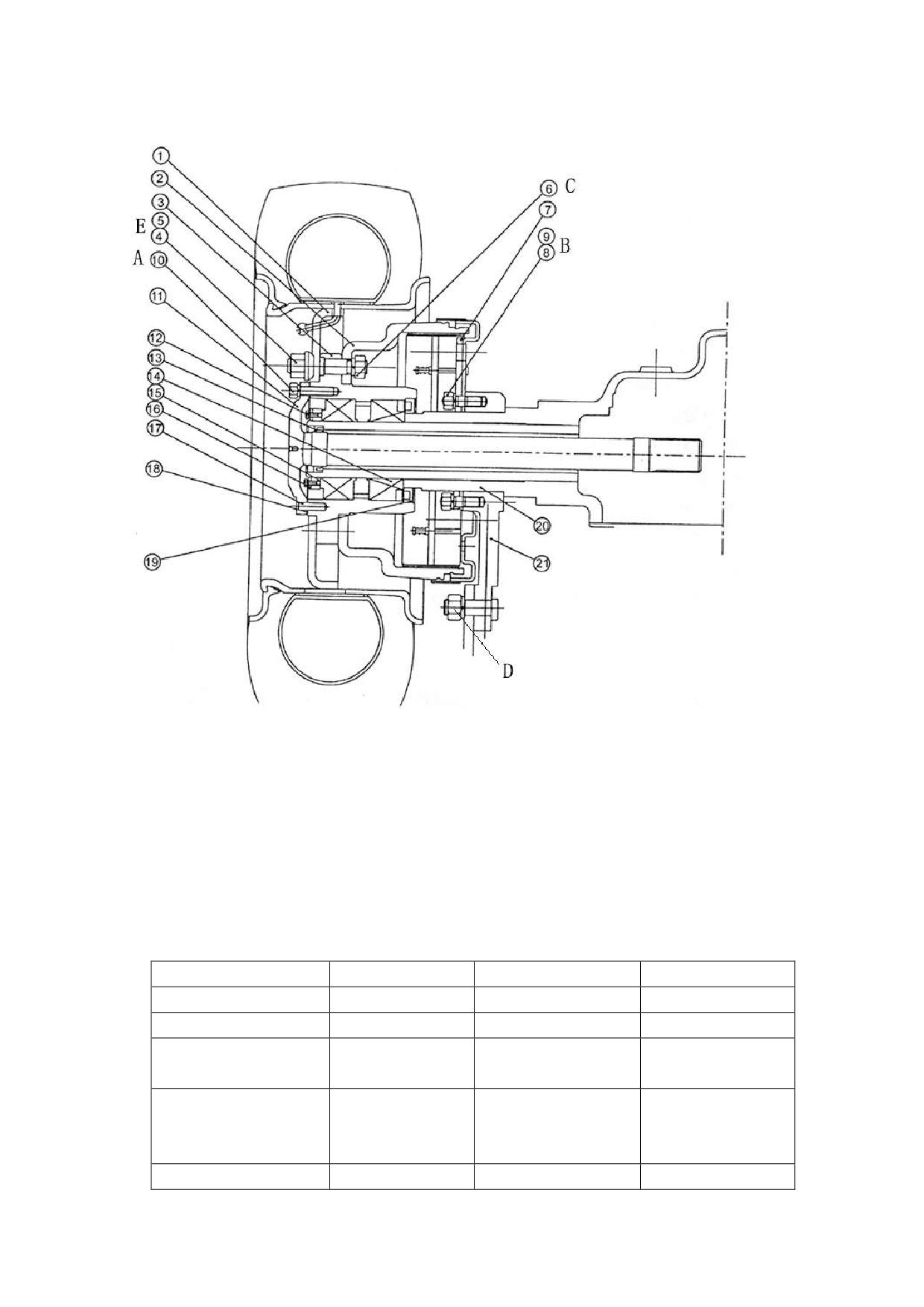
Fig.3-1 Driving axle
1. Rim
2. Brake drum
3. wheel hub
4.Wheel nut
5. Wheel hub bolt
6. Bolt
7.Brake Assembly
8. Wash
9.Bolt
10. Half-axle nut
11. Half axle
12.Bolt
13. Oil seal
14. Taper roller
15. Adjusting nut
bearing
16. Lock nut
17.Pin
18. Paper shim
19. Oil seal
20.Axle case
21. Supporter
Tighten torque: N.m
1-1.8t
2-3t
4-5t
A
44-58
73.5-88.3
105-156
B
76-107
118-147
157-176
nut connecting brake
324-373
260-347
324-373
C
Bolt and nut connecting
324-373
support plate and truck
260-347
324-373
D
E
157-176
441-588
441-588
10
1.3.3Driving axle assemble removal and installation
! WARNING
Be careful when removal and installation driving axle as it is heavy.
1)
Raise front end of forklift truck and support frame with wooden blocks.
2)
Remove mast assembles.
3)
Slightly raise axle with a hoist and place wooden blacks under differential gear carrier and
transmission case.
4)
After placing a pan under axle case, loose oil plug, drain oil from axle case.
5)
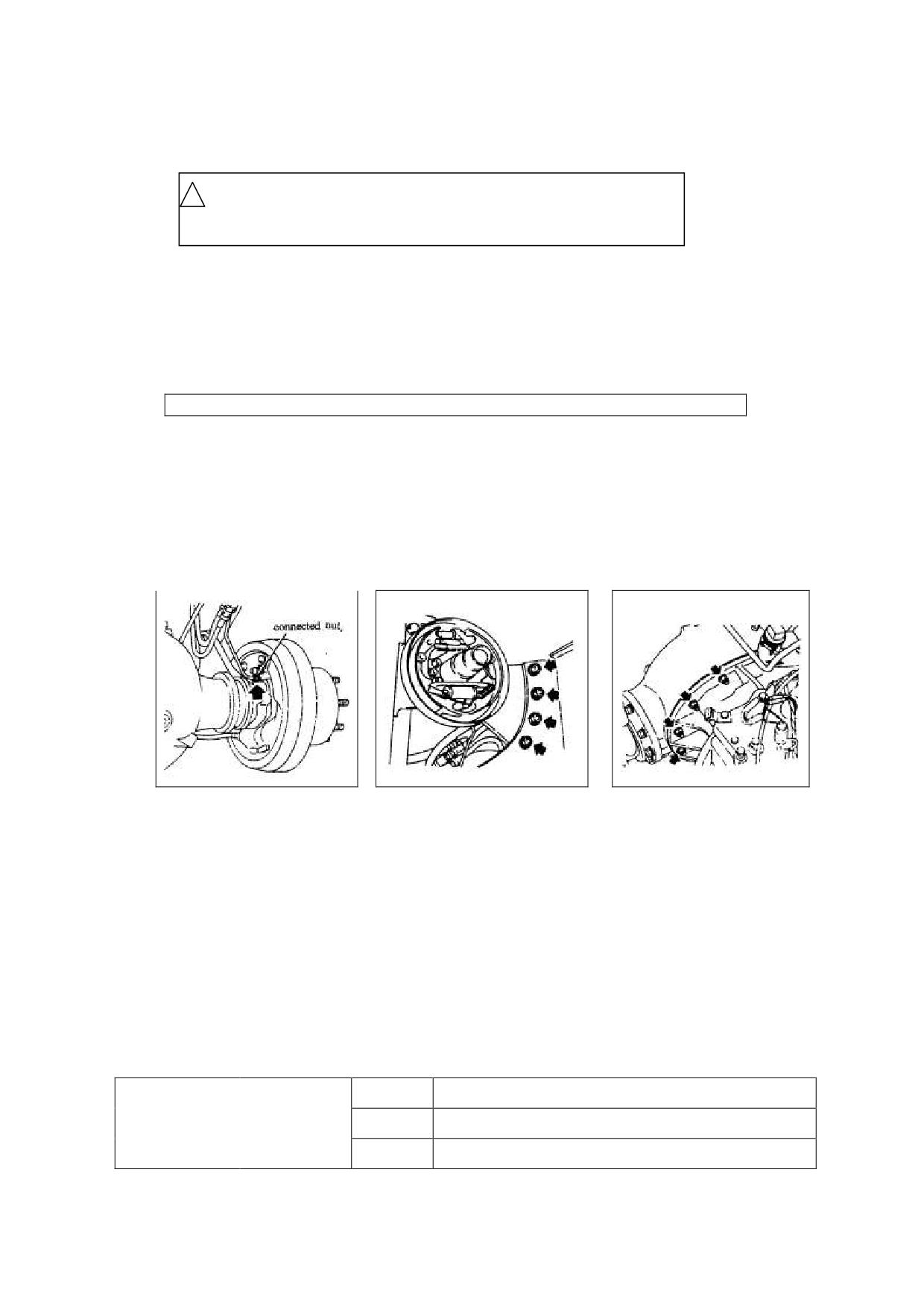
Disconnect brake nuts from left and right cylinders.(see fig.5-1
。
CAUTION:Plug brake tube openings to prevent oil from flowing out.
6)
Disconnect brake cable at hand brake lever.
7)
Remove front wheels.
8)
Remove axle shaft.
9)
Support driving axle with wire ropes and lifting device.
10) Remove bolts securing axle mounting bracket to frame.(see fig.5-2).
11) Remove nuts securing axle case to differential gear carrier.(see fig.5-3).
12) Remove driving axle assemble.
Fig.1-1
Fig.1-2
Fig.1-3
13)Remove brake drum,remove wheel hub.
14)Remove axle mounting bracket and brake component from axle tube.
15)Remove oil seal from axle tube.
16)To install driving axle assemble in the reverse order of removal. Observe the following:
① When installing axle mounting bracket and brake component, apply a coat of calcium grease to axle
tube.
② Apply 1/3~2/3 of volume of calcium grease to wheel hub,then install them on axle tube.
③ Install oil seal with its part number facing to the inside of forklift truck.
④ attach seal tape (PVC, white)to drain plug then installed after cleaned it.
⑤ Replenish axle case with gear oil. Tighten vent plug after clearing.
2.8
1-1.8t
GL-5
Gear oil (L)
3.2
2-3t
85W/90
4.5
4-5t
11
Vent plug should clear instantly to prevent pressure inside of wheel hub from rising.
1.3.4. Axle shaft and wheel hub
Remove
1)Raise the front end of forklift truck and support frame with wooden blocks.
2)Remove front wheel and axle shaft.
3)Remove lock nuts, lock washers, snap ring, felt ring, adjusting nut. Use special tools.
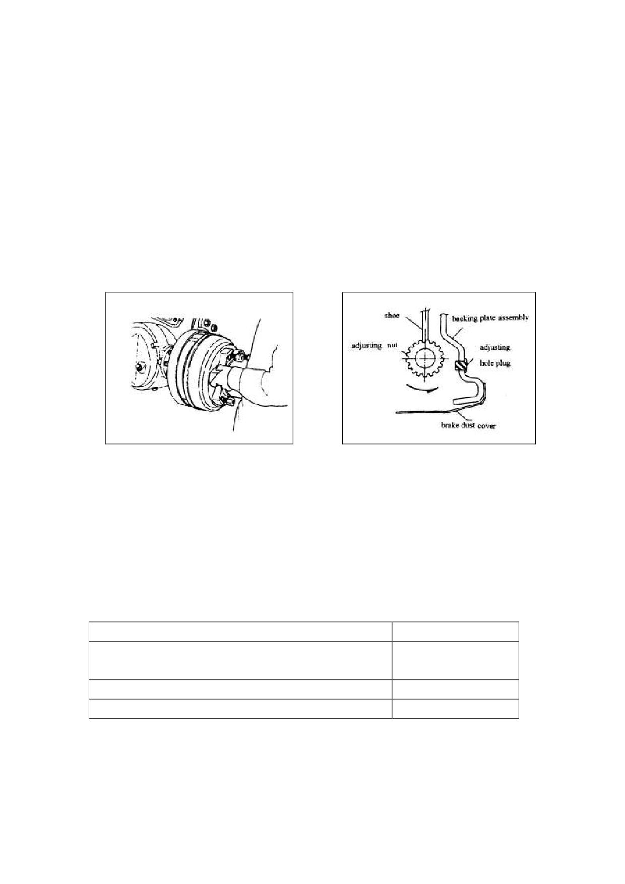
4)Remove brake drum(refer to Fig.5-4);
If brake drum is difficult to remove: a. Remove adjusting hole plug. Then with flat-blade
screwdriver extend adjusting hole, turn adjusting ratchet wheel by 10 notches. To contract brake
shoe lining(refer to Fig.5-5). b. evenly tapping on brake drum with brass bar or wooden mallet.
Fig.1-4
Fig.1-5
5)Remove wheel hub, be careful not to drop bearing inner race.
6)Remove oil seal and inner bearing as an assembly by evenly tapping on periphery of seal with a
wooden mallet and brass bar.
7)Remove bearing outer race from wheel hub by evenly tapping on its periphery with a wooden
mallet.
CAUTION:Be careful not to damage oil seal and outer race.
Inspection
Stepped wear or cracks on axle shaft splines
Replace
Seized, scratched, noisy or rusted bearing or improper rotation of
Replace
rollers
Cracked or damage wheel hub
Replace
Damaged oil seal felt ring.
Replace
Installation
Install reverse order of removal.
12
1.3.5 Bearing adjusting
1)Lubricate on taper roller bearing.
2)Tighten roller bearing lock nut in wheel hub until wheel hub can no longer be rotated with one
hand.
3)From that position, turn back lock nut approx. 600.
4)Turn back wheel hub two or three rotations so that bearing settles down.
5)Again tighten lock nut until it can no longer be rotated with one hand; then turn back approx.600.
6)Install snap ring and settles down felt ring, install lock washer so as to set its hole in the pin of snap
ring. Screw lock nut.
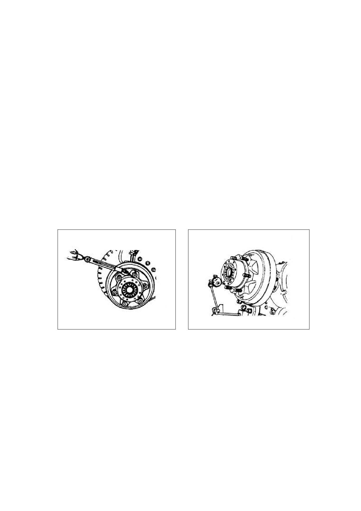
7)Turn wheel hub back and forth two or three rotations to see if rotation starting torque is within
specifications. Rotation starting force: 10~29N(refer to Fig.1-6
;
8)Measure axial play of wheel hub to see if it is within specification. Axial play is less than 0.08mm
(refer to Fig.1-7).
Fig.1-6
Fig.1-7
13
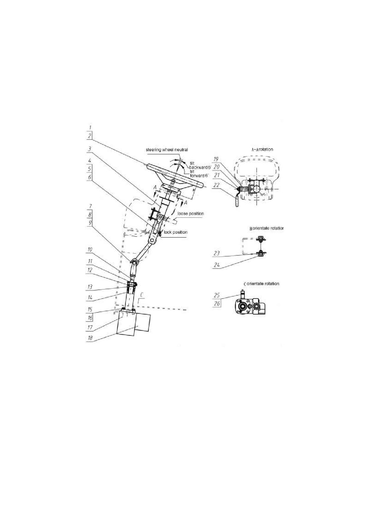
2. Steering system
Steering system include rear steering axle and steering device.
2.1 Steering device
It consists of steering wheel, upside steering column, downside steering column, bearings, steering gear,
priority valve, clamp bolt and hydraulic switch etc. You can adjust the steering angle forward and
backward by yourself. Refer to fig. 2-1.
1. Steering wheel
3.Upside steering
8.Gimbal
10. Down side
12. Bearing
column
steering axle
13. Snap ring
14.Down side
17. Steering gear
18. Priority valve
19. Clamp bolt
steering column
22. Clamp lever
26.Hydraulic
switch
Fig. 2-1 Steering device
14

2.2 Steering axle
2.2.1 General specifications
Axle centre(none for 4-5t)
Axle body
Center support, swing type
type
Vertical play(mm)
0~1
Inner
1-1.5t
79.5º
wheel
2-3t
80º
Turning
Adjusting shim for end
1-1.8t
56º
angle
Outer
shaft of axle thickness
0.5, 1.0, 1.6
wheel
2-3t
55.7º
(mm)
Tyre
0.9MPa
Part No.
N163-220020-000
pressure
Kingpin
wheel hub bearing
Less than
Tighten steering spindle nut until
Kingpin axial play(mm)
0.20
drive wheel hub no longer
Pre-tighten
rotates with one hand. Then
Kingpin adjusting washer
loose 1/8~1/6 rotations.
Or wheel hub rotation starting
thickness(mm)
Part No.
torque at hub blot 10-29.8N
Axial
0.10, 0.30, 0.70
N163-220012-000
Less than 0.10
play(mm)
Truck type
1-1.8t
2-2.5t
3-3.5t
4-5 t
weight Kg
66-68
96-99
98-100
135-150
2.2.2 Trouble diagnoses corrections
condition
Probable cause
Corrective action
loose wheel nut
tighten
·wheel bearing out of adjustment.
adjust
Unstable driving
improperly adjusted shims.
adjust
faulty steering system.
refer to turning system section
insufficient lubrication.
Apply calcium grease
loose bolts and nut.
tighten
Noises
improperly adjusting shim for axle end Shaft.
adjust
damaged joint bearing at two ends of rod.
replace
15
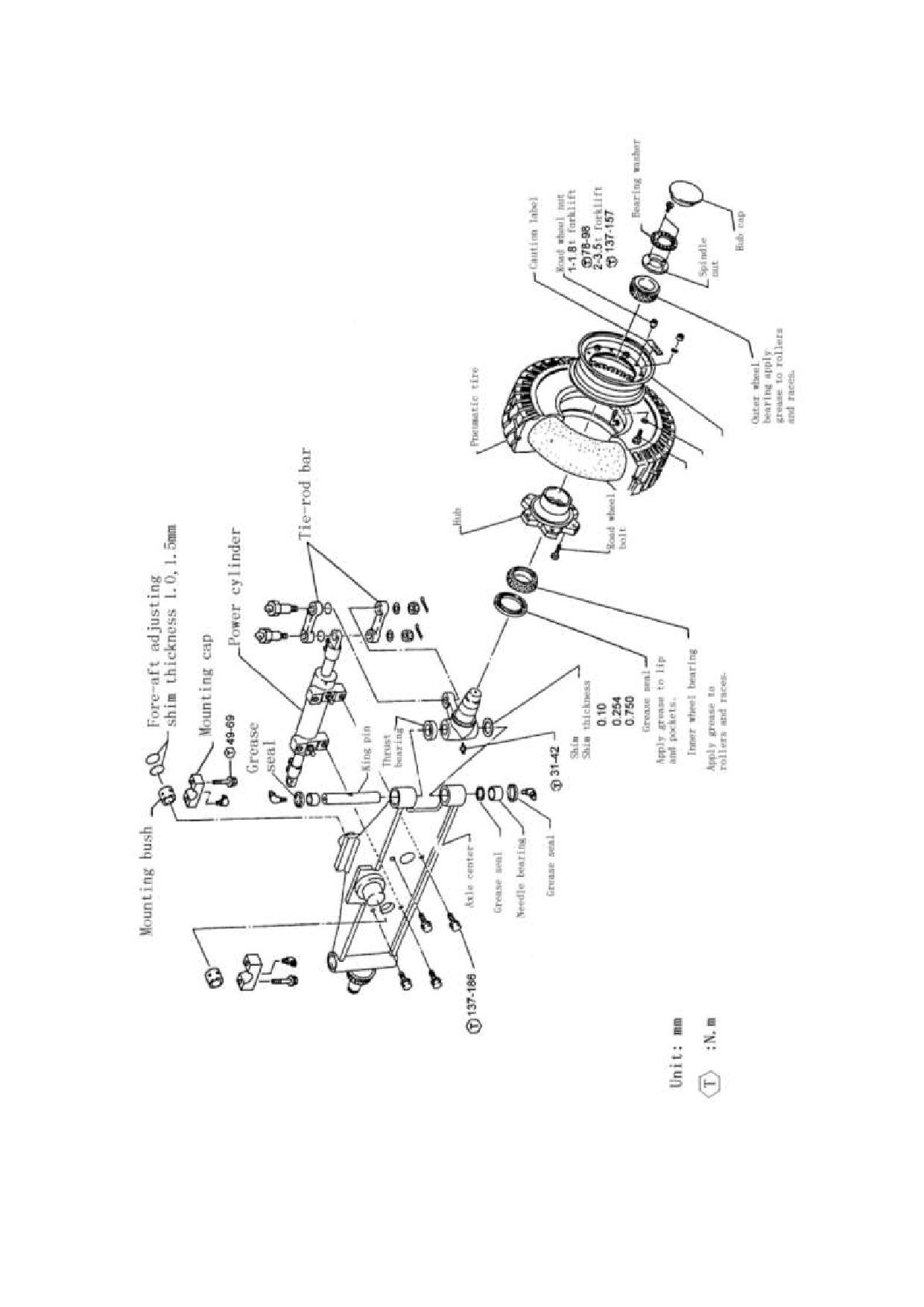
16
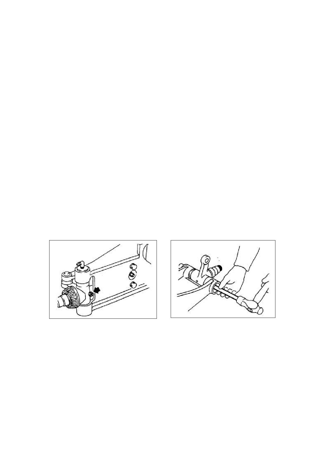
2.2.3 Remove
Wheel hub
1)
Jack up and support forklift truck body with
Wooden blocks.
2)
Remove tire.
3)
Remove hubcap.
4)
Remove steering spindle nut.
5)
Pull off hub assembles.
6)
Remove bearing inner race.
Caution:a. Not to drop bearing inner race.
b. Be careful not to damage oil seal.
2.2.4 Kingpin and steering spindle
1)
Remove rod.
2)
Loose lock bolts.(See fig.2-2
;
3)
Remove grease nipples on kingpin.
4)
Remove kingpin.
Caution:Hold kingpin to prevent it from dropping. (See fig.2-3).
5)
Take off spindle, thrust bearing and shim.
Fig. 2-2
Fig. 2-3
INSPECTION:
1).Replace spindle if cracked.
2).Replace bearing if its rollers or roller surfaces are rusted or nicked.
3).Replace steel sleeve if it distortion, out of round, cracked.
4).Replace thrust bearing and dust cap if them damaged.
17
Installation
To install, reverse the order of removal. Careful observes the following.
1)always insert kingpin from lower side.
2)install thrust bearing, set the tighten-ring below the support and loosen-ring. Pack all grease between
dust proof inside, loosen-ring, and tighten-ring.
3)adjust axial play to specification with shims. Axial plays less than 0.15mm.
4)the character of seal tape faces outside. Apple grease to roller of roller bearing, also apply grease
between lip and groove of seal tape.
5)pack all grease nipple with a sufficient.
2.2.5 Wheel bearing adjustment
1)Slowly rotate hub. Tighten steering spindle nut until it can no longer be rotated with one hand.
2)From that position, turn back steering spindle nut 1/6~1/4 rotation. Measure hub bolt force is 10~30N.
3)Make sure that hub rotates smoothly and that its axial play is within specification. Axial play is less
than 0.10mm.
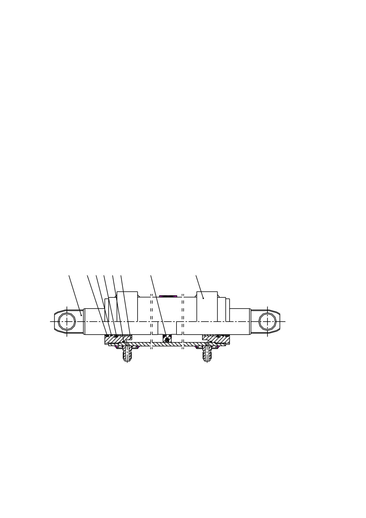
2.2.6 Steering cylinder
1
2
3
4
5
6
7
8
图 2-4 Steering cylinder
1. Piston rod
2.LBH wiper
3. O ring
4.ISI seal ring
5. O ring
6. Guide sleeve
7. Glay ring
8. Crock
18
3. Brake system
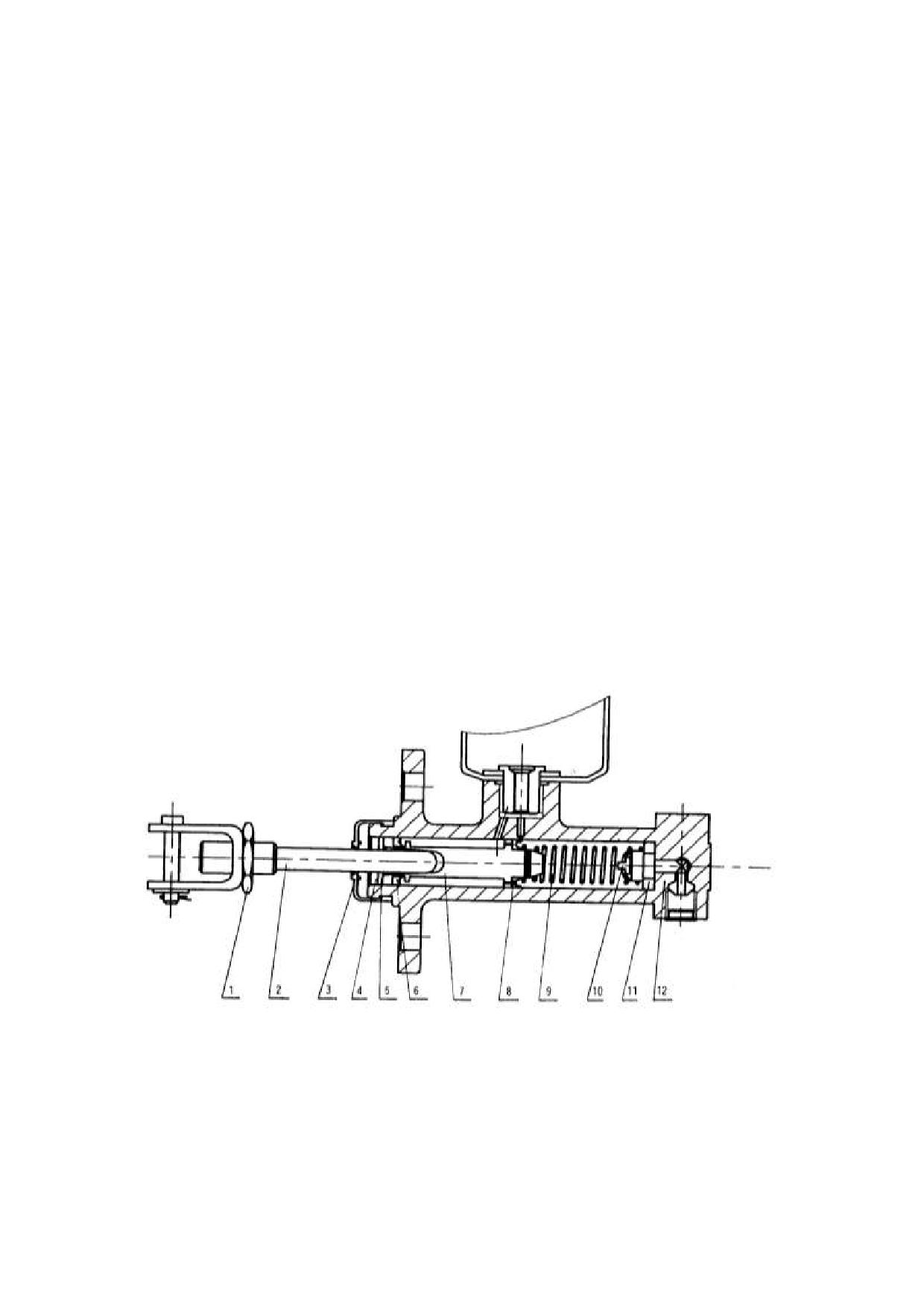
The brake system is the front two-wheel braking type consisting of a master cylinder, brakes and
brake pedal.
3.1 Master cylinder
The master cylinder contains a valve seat, check valve, return spring, primary cup, piston and
secondary cup, which are kept in place with stop washer and stop wire. The exterior of the cylinder is
protected from dust by means of a rubber dust cover. The piston is actuated through the push rod by
operation of the brake pedal. First, as the brake pedal, the push rod pushes the piston forwards. The
brake fluid in the cylinder flows back to the reserve tank through the return port until the primary cup
blocks up the return port. After the primary cup passes the return port, the brake fluid in the cylinder is
pressurized and opens the check valve, flowing through the brake lines to the wheel cylinder. Thus,
each wheel cylinder piston is forced outwards. This brings the brake shoes into contact with the wheel
drum and slows or stops the lift truck.. Meanwhile, the cavity caused behind the piston is filled with
brake fluid led through the return port and inlet port to lubricate the piston. When the brake pedal is
released, the piston is forced back by the return spring. At the same time, the brake fluid in each wheel
cylinder is pressurized by the force of the brake shoe return spring, thus returning into the master
through the check valve. With the piston in its original position, the fluid in the cylinder flows into the
reserve tank through the return port. The brake fluid in the brake lines and wheel cylinders has a
residual pressure proportioned to the set pressure of the check valve, which makes each wheel cylinder
piston cup securely seated to prevent oil leakage and eliminates of vapor lock developing when the lift
truck is sharply broken.
图 3-1 Master cylinder
1. Lock nut
2. Rod
3. Duct cover
4. Stop wire
5. Stop washer
6.Secondary cup
7. Piston
8. Primary cup
9. Spring
10. Check valve
11. Valve seat
12. Cylinder body
19
3.2 Foot brake
3.2.1 Brake
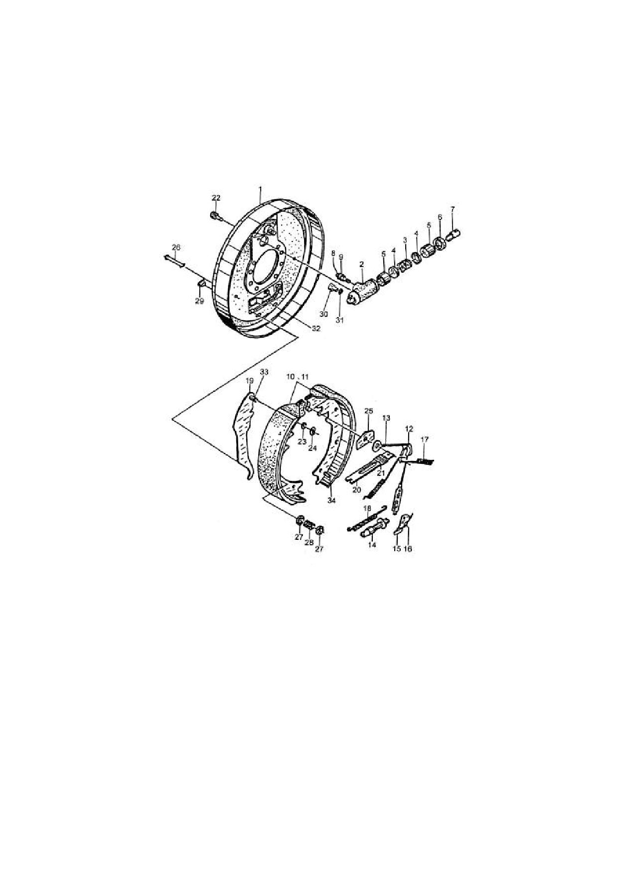
The configuration of the 2-3t right detent can refer to fig 3-2. The configuration of 1-1.8t 、4-5t right
detent Configuration was similitude to 2-3t.
Fig.3-2 2-3t forklift truck right brake assembly
1. Brake mount
2. Wheel cylinder
3. Cylinder return
4. Rubber cap
5.Piston
bracket
body
spring
6.Cylinder dust
7. Push rod
8.Air bleeder cap
9.Air bleeder
10. Brake shoe
cover
screw
assemble (front)
11. Brake shoe
12. Guider
13. Adjuster cable
14.Adjusting bolt
15. Pawl
assemble (rear)
16.Spring
17. Brake shoe
18.Return spring
19.Parking brake
20.Strut level
return spring
rod
21.Spring
22.Bolt
23.Washer
24.Snap ring
25.Guider
26.Spring support
27.Spring bracket
28.Spring
29.Plug
30.Oil connector
rod
31.Bush
32.Brake steel cable
20
3.2.2 Replace brake shoe:
1)
Place the forklift truck on level concrete.
2)
Start engine and raise carriage about 100mm.
3)
Place chocks behind rear wheels to prevent movement of forklift truck.
4)
Loosen wheel nuts two or three turns each.
5)
Tilt mast fully backward, and place a wooden block under each side of outer mast.
!WARNING:
Do not allow wooden blocks to touch front tires.
6)
Tilt mast forward until front tires are raised from surface.
7)
Support forklift truck by putting additional wooden blocks under each side of front-end frame.
8)
Stop engine.
9)
Remove wheel tire nuts and brake drum.
10) Replace brake shoes with new ones.
11) Install brake drum.
12) Adjust shoe to drum clearance:
① Remove adjusting hole plug on the bottom of the brake assemble.
② Insert a flat-blade screwdriver to adjusting hole, turn adjusting ratchet wheel downward to expand
the brake shoes until wheel hub can not be turned by hand.
③ Move the ratchet wheel 2~3 notches to allow the wheel hub to be turned freely, slight friction is
allowed between the brake and shoe lining.
④ Replace the plug.
⑤ Install wheels.
⑥ Properly adjusting pedal stroke.
⑦ Remove blocks.
⑧ make sure no person or obstacle is around forklift, then operate forklift in reverse at 2 to 3 km/h, set
foot on brake pedal 2~3 times.
21
3.3 Hand brake device
The hand brake device adopts a hand-pulling soft brake wire cable device. It makes use of
auto-assist pressure linings type brake together with foot brake. Only when parking truck, use the hand
brake. If it occurs for foot brake malfunction, use hand brake to stop the truck.
condition
Probable cause
Corrective action
·Oil leakage in brake lines.
Correct and replenish.
Insufficient brake
·Air in brake lines.
Bleed air.
force
Improper functioning of master cylinder or
Correct or replace.
wheel cylinder.
·Clogged oil lines.
Clean
·No free play of brake pedal.
Adjust.
Faulty piston cup.
Replace
·Weak or broken return springs.
Replace
Brake dragging
·Clogged master cylinder returns port.
Clean
Clean
·Clogged oil lines.
22

4. Hydraulic system
The high pressure oil from main pump goes to control valve and divide it to two parts by dividing
valve inside control valve: one of them goes to lifting cylinder or tilting cylinder, another part goes to
steering gear with invariable flow to control steering cylinder. When lifting and tilting spool is in
neutral, high pressure oil return oil tank directly from pass way. When pulling lifting spool, high
pressure oil goes by throttle valve and then push piston rod under lifting cylinder piston. When pushing
lifting spool, it is that bottom of lifting cylinder piston connects with low pressure line and then piston
rod drops by deadweight and weight of cargo. In this time, oil from lifting cylinder goes by
unidirectional speed limiting valve so as to control the falling speed. When operating tilting spool, high
pressure oil goes to front house of tilting cylinder and another connects with low pressure line so as to
make mast tilt forward or backward.
Main pump
Trouble
Probable cause
Corrective action
Low oil level in tank.
Add oil to specified level.
No oil from oil
Clean oil line and tank. If oil is dirty,
pump
Clogged suction pipe or strainer.
change.
Worn bearing damaged backup
Replace faulty parts.
ring and O-ring.
Readjust to specified pressure using
Maladjusted relief valve.
Low discharge
pressure gauge.
pressure on oil
Retighten suction side pipe.
Add oil in oil tank.
pump.
Air in oil pump.
Check pump oil seal.
Do not operate pump until bubbles in tank
disappear.
Cavitation due to crushed suction
Adjust or replace crushed hose and clean
hose or clogged strainer.
strainer.
Air being sucked from loose
Retighten each joint.
suction side joint.
replace with new oil having proper
Noisy oil pump
Cavitation due to too high oil
viscosity for temperature at which pump is
viscosity.
to be operate.
to operate when oil temperature is normal.
Bubbles in hydraulic oil.
Determine cause of bubbles and remedy.
Faulty oil seal on pump, faulty
Oil leaking from
O-ring or worn sliding surfaces on
Replace faulty parts.
oil pump
pump.
23

Control valve
Trouble
Probable cause
Corrective action
Loose of pressure-adjust screw.
Readjusted and retighten.
Distorted or damaged pressure-adjust
Pressure of relief
Replace.
spring.
valve is not steady
Worn or blocked relief valve core.
Replace or clean.
or too low.
Pump abated.
Examine and repair pump.
Replace valve core and tilt lock valve
Fork tilt forward
Worn or damaged tilt lock valve.
as an assembly.
when control lever
Broken tilting lock spring.
Replace spring.
is
used
while
engine is off.
Damaged tilt valve plunger O-ring.
Replace O-ring.
Mast is unstable
Malfunctioning tilt relief valve.
Replace tilt relief valve assembly.
when tilting forward.
Valve body and spool valve is worn and
Replace spool valve with specified
Lowering distance
clearance between them is too great.
clearance.
of mast is big when
Spool valve is not in centre.
Keep being in the centre.
spool valve is in
Cylinder seal abated.
Examine and repair cylinder.
the centre.
Taper valve is worn or blocked by dirt.
Replace or clean taper valve.
Damaged or distorted reposition-spring.
Replace spring.
Dirt exist between valve body and spool
Spool valve is not
Clean.
valve.
return neutral
Blocked control device.
Adjusted.
position.
Not coaxial parts at reposition
Reinstall.,be coaxial
Damaged O-ring.
Replace.
Faulty seal of joint.
Check and retighten.
LOOSE SEAL PLATE.
Clean seal plate and retighten blots.
Leakage
Loosed lock-nut of relief valve and
Tighten.
connect-nut between plate and plate.
24
Adjusting the pressure of the main relieve valve
The pressure of the main relieve valve is all ready adjusted in the factory, and it can’t be adjusted
generally. The following is an example of 3t truck to specify how to adjust the pressure.
(1). Put 125 percent of the rated load (2000kg) on the forklift stable.
(2).Step the accelerated pedal to the end, control the lift pole, if the forklift can get the height of
300mm,the main relieve valve is all right. Otherwise, adjust it as step (3).
(3).If the forklift can’t work, enhance the pressure main relieve valve, remove the front soleplate,
loosen the tightening nut of the main relieve valve, screw the adjusting nut clockwise to enhance
the pressure of the main relieve valve. If the height of lift is higher than 300mm, screw the adjust
nut anti-clockwise to reduce the pressure.
(4).Step the accelerated pedal to the end to make the forklift in the height range of 0-300mm. Otherwise,
adjust it as step (3).
Warning:
The load should be put stably.
·Don’t adjust if the pressure is already adjusted correctly.
25
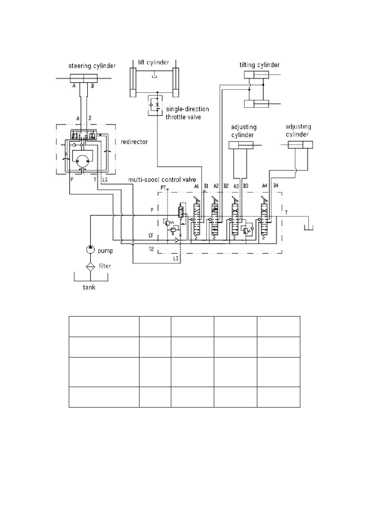
Hydraulic system principle diagram
Tonnage Items
1.3t
1.5t
1.8-3.5t
4-5t
The max. input pressure
16MPa
16MPa
16MPa
16MPa
of redirector
Main safety valve
pressure of multi-spool
12 MPa
15 MPa
17.5 MPa
18.5 MPa
control valve
Rated pressure of gear
20 MPa
20 MPa
20 MPa
20 MPa
pump
26
5. Lifting system
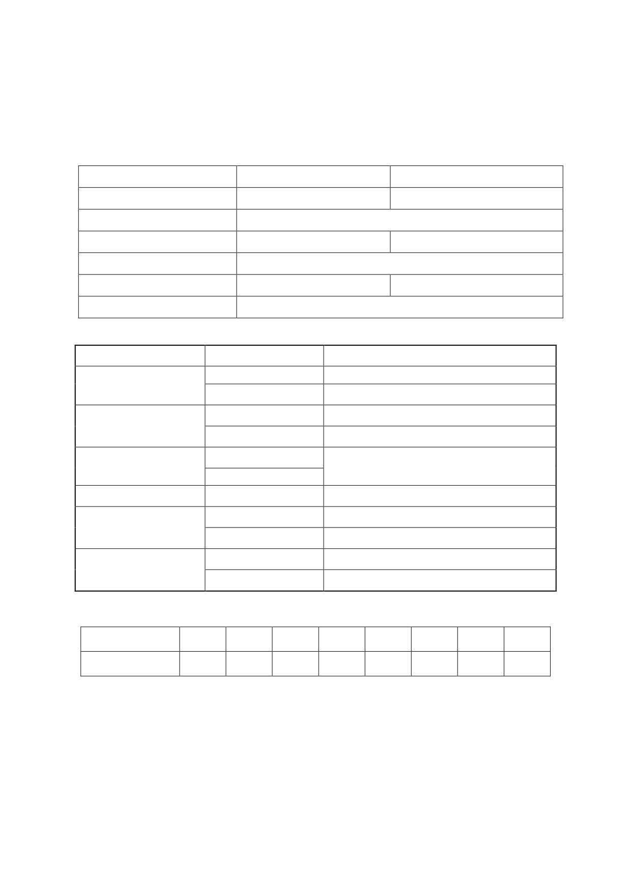
5.1 Data
Inspection and adjustment
Place
Assembly clearance (mm)
Repair clearance(mm)
Mast to lift roller
0.1~0.8
0.2~1
Shims
0.5~1
Mast to back up metal
0.1~0.8
0.2~1
Shims
0.5~1
Inner mast to carriage side roller
0.1~0.6
0.2~1
Lift chain deflection
25~30 mm
Tightening torque
Place
Model or Lifting
N·m
1~1.5t
127-157(M16),245-314(M20 single chain)
Lift chain lock nut
2~3t
176-216(M18)
245-314(M20)
1~1.5t
89-118(M14)
Mast support cap blot
2~3t
176-216(M18)
1~1.5t
Tilt cylinder lock nut
89-118(M14)
2~3t
Lift cylinder bolt(head)
1~3t
76-107(M12)
1~1.5t
22-29(M8)
Lift cylinder bolt(toe)
2~3.5t
44-58(M10)
Lift cylinder fixing bolt
1~1.5t
14-18(M8)
(U type)
2~3t
29-39(M10)
Weight of basal mast
Model of truck
1t
1.5 t
1.8 t
2t
2.5t
3t
4-4.5t
5t
Weight of mast Kg
531
531
531
930
1000
1100
1450
1550
27

5.2 Fault
Fault
Probable cause
Corrective action
1.Tilt cylinder and ring abraded
Replace piston ring tilt cylinder.
Fork arm carrier or
excessively
mast tilt by itself.
2. The hydraulic control valve spring is
Replace it.
inoperative.
The fork arms
1. Caused by piston jamming or bent
Replace the faulty parts.
carrier moves up
piston rod.
and down
2. Too much dirt is accumulated in the
Strip it down and clean.
sluggishly.
cylinder.
1. Carriage bracket assembly out of
Adjust clearance with thrust metal
adjustment.
and carriage side roller.
2. Insufficient clearance between inner
Adjust clearance with rollers.
and outer masts or rollers and mast.
Forks are lifted or
3. Biting foreign materials between
lowered
Remove foreign materials.
moving part.
unsmoothly.
Apply grease on contact surfaces
4. Insufficient lubrication.
of sliding parts.(butter)
5. Bent carriage bracket assembly.
Repair or replace.
Forks are lifted
1. Lift chains out of adjustable.
Adjust lift chains.
unevenly
1. Grease stiffened or dirt accumulated
Clean and lubricate lift rollers.
Lift roller does not
on lift roller and mast sliding surfaces.
rotate
2. Improperly adjusted lift roller.
Adjust.
1. Insufficient lubrication.
Lubricate.
2. Improperly adjusted lift roller, side
Adjust.
roller and back-up metal.
Excessive mast
By adjusting shims and rubber
noise
pad, piston rod is in touch with
3. Rubber pad on lower of outer mast is
bottom of cylinder body after
useless for container fork lift truck.
inner mast is in touch with rubber
pad.
28

Fault
Probable cause
Corrective action
1. Excessive wear occurs between the oil
Replace the worn parts or the oil
pump body and gears, causing too much
pump.
clearance.
2. The lifting jack piston Yx-ring has worn,
Replace Yx-ring.
resulting in excessive inner leaks.
3. Springs of the multiple control valve
and its relief valve are inoperative oil
Replace.
leaks.
4.Excessive wear occurs of the hydraulic
control valve ,resulting in excessive oil
Replace.
Insufficient lift
leaks.
power or no lift
5. Oil leaks occur between the hydraulic
Dismantle for regrinding the joint
movement.
control valve sections.
surfaces and reassemble the valve.
Tighten the joint nuts and inspect
6. Leakage occurs in the hydraulic pipe.
the seal for damage.
Change the wrong hydraulic oil or
7. The hydraulic oil temperature is too
stop operation for reducing the oil
high. Oil viscosity is too low and the rate
temperature. Find out the reasons
is insufficient.
for high oil temperature and
eliminate the trouble.
8. The load carried is beyond the
Observe the lifting capacity limit.
designed capacity.
29
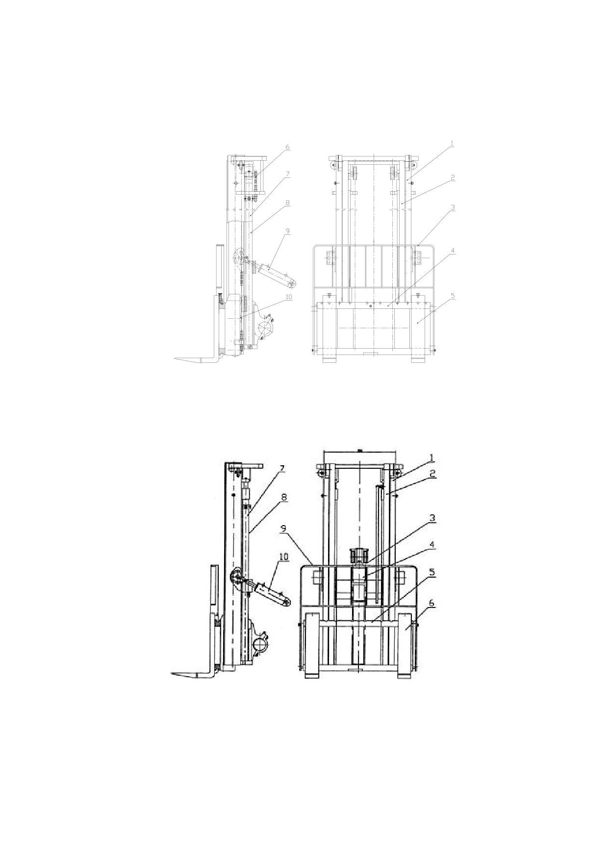
5.3 mast
Basic mast is 3m high, composed of inner and outer mast, fork arm carrier, fork arm, chain and idler
wheel, etc.
Fig5-1 Double lift mast with wide view
1.Outer mast
2.Inner mast
3.Back rest
4. Fork arm carrier
5.Fork
6.Chain
7.Left lifting
8.Right lifting cylinder
9.Tilting cylinder
10.Idler wheel
cylinder
Fig5-2
Double full free lift mast
1. Outer mast
2.Inner mast
3. Chain
4. Free lifting cylinder
5. Fork arm carrier
6. Fork
7.Left lifting
8.Right lifting
9. Fork arms
10.Tilt cylinder
cylinder
cylinder
30
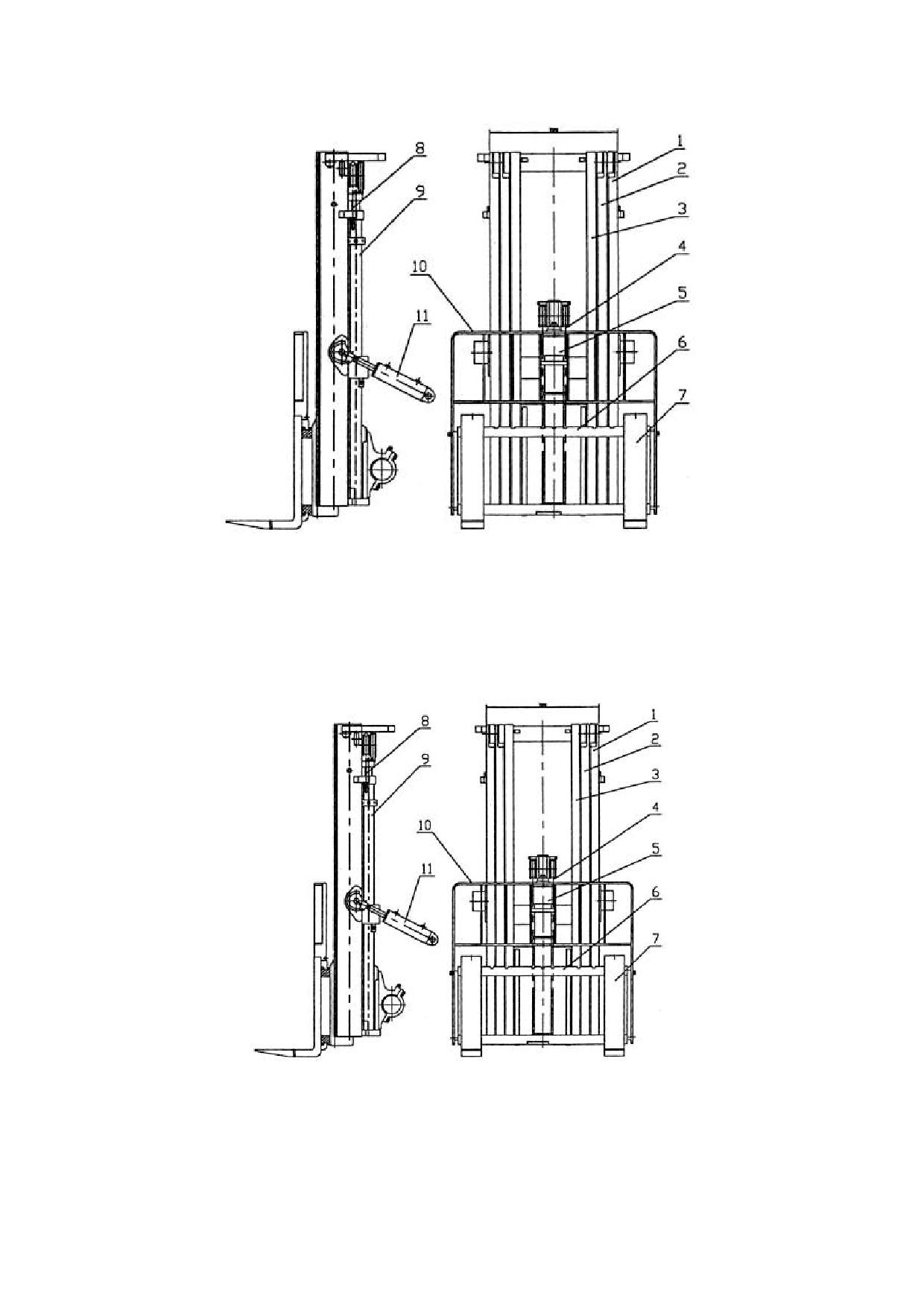
Fig 5-3 Container truck mast
1. Outer mast
2.Inner mast
3. Chain
4. Free lifting cylinder
5. Fork arm carrier
6.Fork
7. Sideway cylinder
8. Left rise cylinder
9. Right rise cylinder
10. Fork arms
11.Tilt cylinder
Fig 5-4 Triple full free lift mast
1. Outer mast
2. Inner mast
3. Chain
4. Free lifting cylinder
5. Fork arm carrier
6. Fork
7. Sideway cylinder
8. Left rise cylinder
9. Right rise cylinder
10. Fork arms
11.Tilt cylinder
31
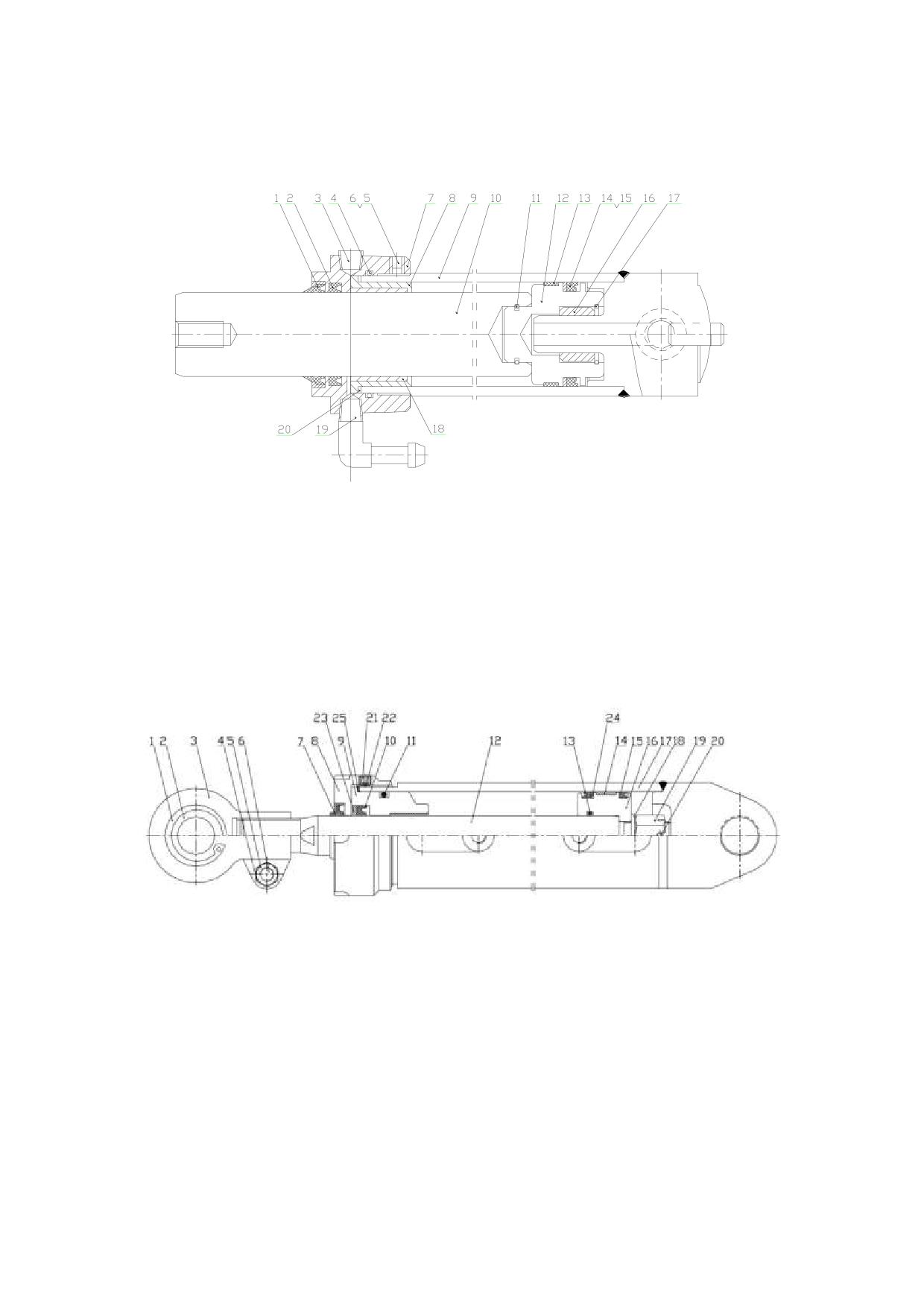
Fig 5-5 Lifting cylinder
1.LBH dust proof
2. ISI ring
3. Plug screw
4. O Ring
5.Piston
6.Bolt
7.Guide
8.bush
9. Cylinder body
10.Piston
11. Snap ring
12. Piston
13. Support ring
14. Back up rings
15. OSI ring
16. Valve guide
17.Snap ring
18. Steel axletree
19.Blowout patch
20.Adjusting washer
5.5 Tilting cylinder
Fig 5-6 Tilting cylinder
1. Retaining
2.Knuckle bearing
3. Support
4.Lubrication
5. Nut
ring
nipple
6. Bolt
7. dust proof
8. Cylinder
9. Guide
10. U ring
11. O ring
12. Piston rod
13. O ring
14. Thimble
15. U ring
16. Piston
17.Cylinder body
18. Washer
19. Nut
20. Pin
21.bolt
22.Nylon tray
23.Snap ring
24. Snap ring
25.Adjusting washer
32
6. Electrical system
6.1 CPD10/15/20/25/30J fork
6.1.1summarize
Curtis PMC 1244 MultiMode controllers are separately excited motor speed controllers designed
for use in a variety of material handling vehicles. These programmable controllers are simple to install,
efficient, and cost effective.
Typical applications include low lifts, stackers, fork lifts, reach trucks, personnel carriers,
counterbalance trucks, order pickers, boom trucks, and other industrial vehicles.
The 1244 MultiMode controller offers smooth, silent, cost effective control of motor speed and
torque. A four quadrant, full-bridge field
Winding control stage is combined with a two quadrants, half-bridge armature power stage to provide
solid state motor reversing and regenerative braking power without additional relays or contactors. The
1244 controller can also be specified to be compatible with CAN Bus communication systems.
These controllers are fully programmable by means of the optional handheld 1307 programmer.
Use of the programmer provides diagnostic and test capability as well as configuration flexibility.
Like all Curtis PMC motor controllers, the 1244 offers superior operator control of the vehicle’s motor
drive speed. Features include:
_ Full-bridge field and half-bridge armature power MOSFET design, providing
• Infinitely variable forward, reverse, drive, and brake control
• Silent high frequency operation
• High efficiency
_ Regenerative braking, providing longer operation on a single battery charge and reducing motor
brush wear and motor heating
_ Programmability through the 1307 handheld programmer
_ Complete diagnostics through the 1307 programmer and the internal Status
LED
_ Two fault outputs provide diagnostics to remotely mounted displays
_ Continuous armature current control, reducing arcing and brush wear
_ Automatic braking when throttle is reduced from either direction; this provides a compression
braking feel and enhances safety by automatically
initiating braking in an operator hands off condition
_ Deceleration Rate, Load Compensation, and Restraint features prevent downhill runaway conditions;
speed is controlled to within approximately
20% of level surface value
_ MultiMode allows four user-selectable vehicle operating personalities
_ Programmable to match individual separately excited motor characteristics
_ Meets or exceeds EEC fault detect requirements
_ Vehicle top speed is controlled and limited in each mode
33
_ Linear temperature and under voltage cutback on motor currents; no sudden loss of power under any
thermal conditions
_ High pedal disable (HPD) and static return to off (SRO) interlocks prevent vehicle runaway at startup
_ Creep speed adjustable from 0% to 25% in each mode
_ Continuous diagnostics during operation, with microprocessor power-on self-test
_ Internal and external watchdog circuits ensure proper software operation
_ Programmable coil drivers provide adjustable contactor pull-in and holding voltages
_ Hour-meter enable output is active whenever the controller is providing motor current
_ Optional Electromagnetic Brake Driver provides automatic control of an electromagnetic brake or
other similar function
34

6.1.2 Failure code
CPD10-30J
Fault table of tow controller
LED code
PROGRAMMER LCD
EXPLANATION
POSSIBLE CAUSE
DISPLAY
1,2
HW FAIL SAFE1-2-3
self-test or watchdog fault
Controller defective.
M-SHORTED
internal M- short to B-
1.Controller defective.
1. Motor field wiring loose.
FIELD OPEN
.Field winding fault
1, 2. Motor field winding open.
1,3
ARM SENSOR
armature current sensor fault
1.Controller defective.
FLD SENSOR
Field current sensor fault
1.Controller defective.
1.VSC input wire open.
2.VSC input wire shorted to B+
SPEED
CONTROL
2,1
VSC signal exceed range
or B-.
FAULT
3.Throttle pot defective.
4. Wrong throttle type selected.
1..Improper seq. of direction and
throttle inputs.
2. Wrong START LOCKOUT
2,3
START LOCKOUT
starting sequence wrong
type selected.
3. Misadjusted throttle pot.
4. Sequencing delay too short.
cont. driver output over
1. Contactor coil shorted.
3,1
CONT DRVR OC
current
1. Main contactor stuck closed.
3,2
MAIN CONT WELDED
welded main contactor
2. Main contactor driver shorted.
internal voltage too low at
1. Controller defective.
3,3
PRECHARGE FAULT
startup
2. External short, or leakage path
to B- on external B+ connection.
MISSING
1 Any contactor coil open or not
missing contactor
CONTACTOR
connected.
3,4
1 Main contactor missing or wire
CONT DNC
main contactor did not close
to coil open.
1. Battery voltage >overvoltage
shutdown limit.
2. Vehicle operating with charger
4,2
OVERVOLTAGE
overvoltage
attached.
3. Battery disconnected during
regen braking.
1.Temperature >85℃ or <
-25℃.
2. Excessive load on vehicle.
Over-/under-temp. cutback
4,3
THERMAL CUTBACK
3. Improper mounting of
controller.
4. Operation in extreme
environments.
35

Fault table of lift (oil pump) controller
LED
PROGRAMMER
EXPLANATION
POSSIBLE CAUSE
code
LCD DISPLAY
NO voltage or controller
off
is not working, error (such
On
as MCII defective)
controller work normally,
0,1
■ ¤
no error
1.
EEPROM miss data
2.
EEPROM data check error,use
1,1
¤ ¤
EEPROM defective
programmer 1311 to change any
parameter can delete the error.
1.
MOSFET short down.
1,2
¤ ¤¤
Hardware defective
2.
Motor circuit is an open circuit.
2,1
¤¤ ¤
Low voltage
Battery voltage is too low.
The function of lifting lock of the
2,2
¤¤ ¤¤
Lifting lock.
controller is touch off.
Order fault ( Startup
Any switch of SS1-SS4 closes earlier
2,3
¤¤ ¤¤¤
lockout)
than KSI or INTERLOCK.
1.
Main contact bonded。
3,2
¤¤¤ ¤¤
Contact err
2.
The set of parameter ―CONTACT
CNTRL‖ is wrong.
1.
Pre-charge circuit work with err.
3,3
¤¤¤ ¤¤¤
Pre-charge fault
2.
Motor short down.
1.
The connection of main contact
Contact has not been
3,4
¤¤¤ ¤¤¤¤
coil loose.
installed or is not close.
2.
Main contact works abnormally.
The voltage of battery is lower than the
4,1
¤¤¤¤ ¤
Low -voltage protect.
set value of ―LOVOLT CUTBACK‖
4,2
¤¤¤¤ ¤¤
Over-voltage protect.
The battery voltage is too high.
1.
The temperature of controller is
temperature
protect
too high or too low.
4,3
¤¤¤¤ ¤¤¤
(over-/under-temp)
2.
Temperature
sensor
works
abnormal.
36
6.2 CPD10/15/20/25/30/35J C1、CPD10/15/18/20/25/30/35J C2、CPD40/45/50J C2
fork
6.2.1 Summarize
CURTIS company procreates controller ,adopt international advanced closed loop system and
advanced control technique。Designing large screen instrument,can clear display ―electric quantity‖、
―speed‖、―total time of run ‖ and so on information。Designation adopt code plus character manner,
increase maintain efficiency。Four work models can be set through meter so as to suitable for different
condition.
(1)Actuating motor
Actuating motor adopt three-phase alternating current frequency conversion electromotor,increase
conversion efficiency,not have commentator brush in order not to maintenance 。
(2)Lift motor
Lift motor JC1 is direct current motor, so is the motor of J series truck. Lift motor JC2 adopts
three-phase alternating electromotor,increase conversion efficiency,not have commentator brush in
order not to maintenance.
(3)SAFETY & PROTECTION FEATURES
① Reverse Polarity of the battery
②Connection errors
③All inputs are protected against connections errors.
④Current overload protection
⑤it have detecting element,control peak current.
⑥Thermal protection
If the controller temperature exceeds 85°C, the maximum current reduces in proportion to the
thermal increase. The temperature can never exceed 115
C.
If the electric machinery temperature exceeds 145°C, the maximum current reduces in proportion to the
thermal increase. The temperature can never exceed 165
C.
⑦Low Battery charge
When the battery charge is low, the maximum current is reduced proportionally to the battery
discharge.
⑧External Agents
Electric control is hermetical .The chopper is protected against dust and spray of liquid to
economy.
⑨Protection against accidental Start Up
A precise sequence of operations is necessary before the machine will start. Operation can not
commence if these operations are not carried out correctly. Requests for drive must be made after
closing the Key Switch.
(4)OPERATIONAL FEATURES
① Feedback control system make the vehicle speed follow accelerator ,whether low speed or not
37
high speed easy control .
② two archives speed and acceleration design ,can apply to most situation.
③ regeneration technology make change direction of fork even smooth。
④ three regenerative braking mode :
A、acceleration pedal part release appear regenerative braking,
B、direction reverse regenerative braking,
C、ramp downslide appear regenerative braking,
Except increase security drive,reclaim part of electric energy,prolong work time of every time .
⑤ control speed during downgrade: speed lie on accelerator 。if speed exceed set point,controller
may automatic braking,this give optimal ramp.
Notice:
1 .Maintain electric control ,must first cut off electrical source,then hold 10-100ohmic resistance
join controller anode and cathode,release residual voltage in the capacitor, or else you may meet
tip-and-run danger.
2.Magnetic and radiation have some effect to inverter,long time effect may mangle controller, So
need apart form magnetic and radiation.
38

6.2.2 Error code
CPD10-35J C1 EC ERROR CODE TABLE
There are two LEDs including a yellow LED and a red LED. The two LEDs have four different display
modes, indicating the type of information they are providing.
DISPLAY
STATUS
Controller is not powered on, has a dead
Neither LED illuminated
battery, or is severely damaged.
Yellow LED flashing
Controller is operating normally.
Yellow and red LEDs both on solid
Controller is in Flash program mode.
Red LED and yellow LED flashing alternately
Controller has detected a fault.
TOWING CONTROLLER ERROR CODE TABLE
CODE
PROGRAMMER
POSSIBLE CAUSE
LCD DISPLAY
1,2
Controller Overcurrent
1. External short of phase U, V, or W motor connections.
2. Motor parameters are mis-tuned.
3. Controller defective.
1,3
Current Sensor Fault
1. Leakage to vehicle frame from phase U, V, or W (short in motor stator).
2. Controller defective.
1,4
Precharge Failed
1. External load on capacitor bank (B+ connection stud) that prevents the
capacitor bank from charging.
2. See 1311 menu Monitor » Battery: Capacitor Voltage.
1,5
Controller
Severe
1. Controller is operating in an extreme environment.
Undertemp
2. See 1311 menu Monitor » Controller: Temperature.
1,6
Controller
Severe
1. Controller is operating in an extreme environment.
Overtemp
2. Excessive load on vehicle.
3. Improper mounting of controller.
4. See 1311 menu Monitor » Controller: Temperature.
1,7
Severe Undervoltage
1. Battery Menu parameters are misadjusted.
2. Non-controller system drain on battery.
3. Battery resistance too high.
4. Battery disconnected while driving.
5. See 1311 menu Monitor » Battery: Capacitor Voltage.
6. Blown B+ fuse or main contactor did not close.
1,8
Severe Overvoltage
1. Battery Menu parameters are misadjusted.
2. Battery resistance too high for given regen current.
3. Battery disconnected while regen braking.
4. See 1311 menu Monitor » Battery: Capacitor Voltage.
2,1
Controller Undertemp
1. Controller is performance-limited at this temperature.
Cutback
2. Controller is operating in an extreme environment.
3. See 1311 menu Monitor » Controller: Temperature.
39

CODE
PROGRAMMER
POSSIBLE CAUSE
LCD DISPLAY
2,2
Controller Overtemp
1. Controller is performance-limited at this temperature.
Cutback
2. Controller is operating in an extreme environment.
3. Excessive load on vehicle.
4. Improper mounting of controller.
5. See 1311 menu Monitor » Controller: Temperature.
2,3
Undervoltage Cutback
1. Normal operation. Fault shows that the batteries need recharging.
Controller is performance limited at this voltage.
2. Battery parameters are misadjusted.
3. Non-controller system drain on battery
4. Battery resistance too high.
5. Battery disconnected while driving.
6. See 1311 menu Monitor » Battery: Capacitor Voltage.
7. Blown B+ fuse or main contactor did not close.
2,4
Overvoltage Cutback
1. Normal operation. Fault shows that regen braking currents elevated the
battery voltage during regen braking Controller is performance limited at
this voltage.
2. Battery parameters are misadjusted.
3. Battery resistance too high for given regen current.
4. Battery disconnected while regen braking
5. See 1311 menu Monitor » Battery: Capacitor Voltage.
2,5
+5V Supply Failure
1. External load impedance on the +5V supply (pin 26) is too low.
2. See 1311 menu Monitor » outputs: 5 Volts and Ext Supply Current.
2,6
Digital Out 6
1. External load impedance on Digital Output 6 driver (pin 19) is too low.
Overcurrent
2,7
Digital Out 7
1. External load impedance on Digital Output 7 driver (pin 20) is too low.
Overcurrent
2,8
Motor Temp Hot
1. Motor temperature is at or above the programmed Temperature Hot
Cutback
setting, and the requested current is
being cut back.
2. Motor Temperature Control Menu parameters are mis-tuned.
3. See 1311 menus Monitor » Motor: Temperature and Monitor » Inputs:
Analog2.
4. If the application doesn’t use a motor thermistor, Temp Compensation
and Temp Cutback should be programmed Off.
2,9
Motor Temp Sensor
1. Motor thermistor is not connected properly.
Fault
2. If the application doesn’t use a motor thermistor, Temp Compensation
and Temp Cutback should be programmed Off.
3. See 1311 menus Monitor » Motor: Temperature and Monitor » Inputs:
Analog2.
40

CODE
PROGRAMMER LCD
POSSIBLE CAUSE
DISPLAY
3,1
Coil 1 Driver
1. Open or short on driver load.
Open/Short
2. Dirty connector pins.
3. Bad crimps or faulty wiring.
3,1
Main Open/Short
1. Open or short on driver load.
2. Dirty connector pins.
3. Bad crimps or faulty wiring.
3,2
Coil2 Driver
1. Open or short on driver load.
Open/Short
2. Dirty connector pins.
3. Bad crimps or faulty wiring.
3,2
EM Brake Open/Short
1. Open or short on driver load.
2. Dirty connector pins.
3. Bad crimps or faulty wiring.
3,3
Coil3 Driver
1. Open or short on driver load.
Open/Short
2. Dirty connector pins.
3. Bad crimps or faulty wiring.
3,4
Coil4 Driver
1. Open or short on driver load.
Open/Short
2. Dirty connector pins.
3. Bad crimps or faulty wiring.
3,5
PD Open/Short
1. Open or short on driver load.
2. Dirty connector pins.
3. Bad crimps or faulty wiring.
3,6
Encoder Fault
1. Motor encoder failure.
2. Bad crimps or faulty wiring.
3. See 1311 menu Monitor » Motor: Motor RPM.
3,7
Motor Open
1. Motor phase is open.
2. Bad crimps or faulty wiring.
3,8
Main
Contactor
1. Main contactor tips are welded closed.
Welded
2. Motor phase U is disconnected or open.
3. An alternate voltage path (such as an external precharge resistor) is
providing a current to the capacitor bank (B+ connection stud).
3,9
Main Contactor Did
1. Main contactor did not close.
Not Close
2. Main contactor tips are oxidized, burned, or not making good contact.
3. External load on capacitor bank (B+ connection stud) that prevents
capacitor bank from charging.
4. Blown B+ fuse.
41

CODE
PROGRAMMER LCD
POSSIBLE CAUSE
DISPLAY
4,1
Throttle Wiper High
1. Throttle pot wiper voltage too high.
2. See 1311 menu Monitor » Inputs: Throttle Pot.
4,2
Throttle Wiper Low
1. Throttle pot wiper voltage too low.
2. See 1311 menu Monitor » Inputs: Throttle Pot.
4,3
Brake Wiper High
1. Brake pot wiper voltage too high.
2. See 1311 menu Monitor » Inputs: Brake Pot.
4,4
Brake Wiper Low
1. Brake pot wiper voltage too low.
2. See 1311 menu Monitor » Inputs: Brake Pot.
4,5
Pot Low Overcurrent
1. Combined pot resistance connected to pot low is too low.
2. See 1311 menu Monitor » Outputs: Pot Low.
4,6
EEPROM Failure
1. Failure to write to EEPROM memory. This can be caused by
EEPROM memory writes initiated by VCL, by the CAN bus, by
adjusting parameters with the 1311, or by loading new software into the
controller.
4,7
HPD/Sequencing Fault
1. KSI, interlock, direction, and throttle inputs applied in incorrect
sequence.
2. Faulty wiring, crimps, or switches at KSI, interlock, direction, or throttle
inputs.
3. See 1311 menu Monitor » Inputs.
4,7
Emer Rev HPD
1. Emergency Reverse operation has concluded, but the throttle, forward
and reverse inputs, and interlock have not been returned to neutral.
4,9
Parameter
Change
1. This is a safety fault caused by a change in certain 1311 parameter
Fault
settings so that the vehicle will not operate until KSI is cycled. For
example, if a user changes the Throttle Type this fault will appear and
require cycling KSI before the vehicle can operate.
6,8
VCL Runtime Error
1. VCL code encountered a runtime VCL error.
2. See 1311 menu Monitor » Controller: VCL Error Module and VCL
Error. This error can then be compared to the runtime VCL module ID and
error code definitions found in the specific OS system information file.
6,9
External Supply Out of
1. External load on the 5V and 12V supplies draws either too much or too
Range
little current.
2. Fault Checking Menu parameters Ext Supply Max and Ext Supply Min
are mis-tuned.
3. See 1311 menu Monitor » Outputs: Ext Supply Current.
42

CODE
PROGRAMMER
POSSIBLE CAUSE
LCD DISPLAY
7,1
OS General
1. Internal controller fault.
7,2
PDO Timeout
1. Time between CAN PDO messages received exceeded the PDO
Timeout Period.
7,3
Stall Detect
1. Stalled motor.
2. Motor encoder failure.
3. Bad crimps or faulty wiring.
4. Problems with power supply for the motor encoder.
5. See 1311 menu Monitor » Motor: Motor RPM.
8,7
Motor
1. Motor characterization failed during the motor characterization process.
Characterization Fault
8,8
Encoder
1. Encoder characterization failed during the motor characterization
Characterization Fault
process.
2. Motor encoder pulse rate is not a standard value (32, 48, 64, 80 ppr).
8,9
Motor Type Fault
1. The Motor type parameter value is out of range.
9,2
EM Brake Failed to
1. Vehicle movement sensed after the EM Brake has been commanded to
Set
set.
2. EM Brake will not hold the motor from rotating.
9,3
Limited
Operating
1. Limited Operating Strategy (LOS) control mode has been activated, as
Strategy(LOS)
a result of either an Encoder Fault (Code 36) or a Stall Detect Fault (Code
73).
2. Motor encoder failure.
3. Bad crimps or faulty wiring.
4. Vehicle is stalled.
9,4
Emer Rev Timeout
1. Emergency Reverse was activated and concluded because the EMR
Timeout timer has expired.
2. The emergency reverse input is stuck On.
Lifting (pump) controller error code table is the same as that of CPD10-30J.
CPD10/15/18/20/25/30/35J C2、CPD40/45/50J C2 EC ERROR CODE TABLE
Lifting (pump) controller error code table is the same as that of CPD10-30J C1
Towing controller error code table is the same as that of CPD10-30J C1
43
6.3 CPD10/15/20/25/30J D1 fork
6.3.1 Summarize
INMOTION company procreates controller ,adopt international advanced closed loop system and
advanced control technique。Designing large screen instrument,can clear display ―electric quantity‖、
―speed‖、―total time of run ‖,―work time of drive ‖,―work time of lift ‖and so on information。
Designation adopt code plus character manner,increase maintain efficiency。It also through meter
check periphery component to come true function of handset
(1) Actuating motor
Actuating motor adopt three-phase alternating current frequency conversion electromotor,increase
conversion efficiency,not have commentator brush in order not to maintenance 。
(2) Lift motor
Lift motor adopt three-phase alternating electromotor ,increase conversion efficiency,not have
commentator brush in order not to maintenance.
(3) Safety & protection features
① Reverse Polarity of the battery
② Connection errors
③ All inputs are protected against connections errors.
④ Current overload protection
⑤ It have detecting element,control peak current.
⑥ Thermal protection
If the controller temperature exceeds 85°C, the maximum current reduces in proportion to the thermal
increase. The temperature can never exceed 115
C.
If the electric machinery temperature exceeds 145°C, the maximum current reduces in proportion to the
thermal increase. The temperature can never exceed 165
C.
⑦ Low Battery charge
When the battery charge is low, the maximum current is reduced proportionally to the battery
discharge.
⑧ External Agents
Electric control is hermetical .The chopper is protected against dust and spray of liquid to economy.
⑨ Protection against accidental Start Up
A precise sequence of operations is necessary before the machine will start. Operation cannot
commence if these operations are not carried out correctly. Requests for drive must be made after
closing the Key Switch.
(4) Operational features
① Feedback control system make the vehicle speed follow accelerator ,whether low speed or not
high speed easy control .
② Two archives speed and acceleration design ,can apply to most situation.
③ Regeneration technology make change direction of fork even smooth。
44
④ Three regenerative braking mode :
A、acceleration pedal part release appear regenerative braking,
B direction reverse regenerative braking,
C、 ramp downslide appear regenerative braking,
Except increase security drive,reclaim part of electric energy,prolong work time of every
time .
⑤ Control speed during downgrade: speed lie on accelerator 。if speed exceed set point,controller
may automatic braking,this give optimal ramp
Notice:
1 .Maintain electric control ,must first cut off electrical source,then hold 10-100ohmic resistance
join controller anode and cathode,release residual voltage in the capacitor, or else you may meet
tip-and-run danger.
2.Magnetic and radiation have some effect to inverter,long time effect may mangle controller, So
need apart form magnetic and radiation.
45

6.3.2 Error code
(1) Errors detected by VMC20
Code.
Source
Condition
When
Tract
Main
PS
Reset
Remark
101
Switch startup error
ACCEL switch active at startup
KEY→ON
OFF
ON
-
ACC SWITCH=OFF
Traction setspeed=0
102
Switch startup error
FW|REV switch active at startup
KEY→ON
OFF
ON
FW=REV= OFF
Traction setspeed=0
103
Direction
switch
FW and REV ON at the same time
KEY=ON
OFF
ON
KEY=OFF
Traction setspeed=0
-
error
104
Accel pot error
Pot voltage > 95% or Pot voltage <
KEY=ON
ON
ON
KEY=OFF
Traction setspeed=0
-
5% of VX_out
105
Accel switch error
Voltage > 30% when ACC switch
KEY=ON
ON
ON
KEY=OFF
Traction setspeed=0
-
is not active
107
Battery
under
48V:Less than 28.2V/.8s
KEY=ON
OFF
OFF
KEY=OFF
Detected by VMC20, not by ACS.
-
voltage
36V: Less than 24.8V/.8s
108
ACS under voltage
Voltage < limit (Parameter) for
KEY=ON
OFF
OFF
KEY=OFF
Detected by VMC20, not by ACS
-
more than 0.8sec
109
Battery over voltage
More than 65V/0.8s
KEY=ON
OFF
OFF
KEY=OFF
Detected by VMC20, not by ACS.
-
110
ACS over voltage
Voltage > limit (Parameter) for
KEY=ON
OFF
OFF
KEY=OFF
Detected by VMC20, not by ACS
-
more than 0.8sec
111
Communication
See 5.2.1.
KEY=ON
OFF
ON
KEY=OFF
Traction setspeed=0
-
error
KEY=OFF
Only happens at the place where the
112
PM brush wear
wear and tearsensor = ON
KEY=ON
-
option sensor install.
-
ON
KEY=OFF
Only happens at the place where the
113
PM thermal
PMheat sensor = ON
KEY=ON
-
option sensor install.
OFF
ON
Charge a battery.
114
Battery low voltage
batteryLED = ON
KEY=ON
-
OFF
ON
KEY=OFF
Connect with the engineer of Danaher
115
Startup error
Startup interior error
KEY=ON
46

(2) Errors detected by drive ACS (EMCY)
Code
Source
Condition
When
Tract
Main
PS
Reset
Remark
Short circuit
ACS is shorted or motor terminals
KEY=ON
ACS may be damaged if short
251
OFF
ON
OFF
KEY=OFF
are shorted
circuit is internal.
252
ACS over temperature
ACS hs temp > 115 degC
KEY=ON
OFF
ON
ON
KEY=OFF
Motor
over
Motor temp > 185 degC
KEY=ON
253
OFF
ON
ON
KEY=OFF
temperature
ACS current sensor
ACS current sensor error
KEY→ON
ACS must be repaired
254
OFF
ON
ON
KEY=OFF
error
Charging timeout
ACS capacitors are not charged
KEY→ON
Check charging circuit
255
OFF
ON
ON
KEY=OFF
within 10sec from power on
ACS no response
ACS does not respond at startup
KEY=ON
Check CAN bus wiring.
256
OFF
ON
ON
KEY=OFF
ACS PDO timeout
ACS CAN open timeout (detected
KEY=ON
Check CAN bus wiring.
257
OFF
ON
ON
KEY=OFF
by VMC20)
ACS SDO error
ACS SDO error (wrong SW
KEY=ON
Check SW version
258
OFF
ON
ON
KEY=OFF
version)
CANopen timeout
ACS CAN open timeout (detected
KEY=ON
Check CAN bus wiring
259
OFF
ON
ON
KEY=OFF
by VMC20)
ACS low voltage trip
ACS voltage <15V
KEY=ON
Instantaneous voltage
260
OFF
ON
ON
KEY=OFF
ACS high voltage trip
ACS voltage > 68V (software)
KEY=ON
Instantaneous voltage
261
OFF
ON
ON
KEY=OFF
ACS high voltage trip
ACS voltage >68V (hardware)
KEY=ON
Instantaneous voltage
262
OFF
ON
ON
KEY=OFF
ACS PCB temp > 115 ℃
263
ACS PCB temp trip
KEY=ON
OFF
ON
ON
KEY=OFF
(only GEN4,GEN5not )
Other urgency instance from
264
Other error
KEY=ON
OFF
ON
ON
KEY=OFF
ACS
47

(3)Errors detected by drive ACS (Warning)
Code
Source
Condition
When
Tract
Main
PS
Reset
Remark
ACS low temp warning
ACS heat sink temp < -20 ℃
KEY=ON
ON
ON
KEY=OFF or Heat
Lowest Accel will be used.
201
ON
sink temp normal
ACS high temp warning
ACS heat sink temp > 85 ℃
KEY=ON
ON
ON
KEY=OFF or Heat
Lowest Accel will be used.
202
ON
sink temp normal
203
Motor high temp warning
Motor temp > 145 ℃
KEY=ON
ON
ON
ON
KEY=OFF
Lowest Accel will be used.
Heat sink temp sensor error
ACS heat sink temp
KEY=ON
ON
ON
KEY=OFF
Lowest Accel will be used.
204
ON
sensor error
205
Motor low temp warning
Motor temp < -50 ℃
KEY=ON
ON
ON
ON
KEY=OFF
Lowest Accel will be used.
Motor temp sensor error
Motor temp sensor
KEY=ON
ON
ON
KEY=OFF or sensor
Lowest Accel will be used.
206
ON
not connected or short circuit
connected
Speed feedback sensor error
Speed feedback sensor
KEY=ON
ON
ON
KEY=OFF or sensor
ACS can not control speed
207
ON
not connected / short circuit
connected
correctly. No driving allowed.
ACS high voltage warning
ACS voltage > 68V
KEY=ON
ON
ON
KEY=OFF or voltage
Lowest Accel will be used.
208
ON
back to normal
ACS low voltage warning
ACS voltage < 22.5V
KEY=ON
ON
ON
KEY=OFF or voltage
Lowest Accel will be used.
209
ON
back to normal
ACS default values loaded
Default parameters are used
KEY=ON
ON
ON
KEY=OFF
Turn the key s witch off and on again.
210
ON
in ACS
Power reduce
Power is reduced (by
KEY=ON
ON
ON
KEY=OFF
211
ON
some warning condition)
Checksum error
Calibration parameter
KEY=ON
ON
ON
KEY=OFF
212
ON
checksum error
213
PCB temp <-20 ℃
KEY=ON
ON
ON
KEY=OFF
PCB low temp warning
ON
(onlyGEN4,GEN5 not )
PCB temp > 100 ℃
214
PCB high temp warning
KEY=ON
ON
ON
ON
KEY=OFF
(only GEN4,GEN5 not )
PCB temperature sensor error
215
PCB sensor error
KEY=ON
ON
ON
ON
KEY=OFF
(only GEN4,GEN5 not )
216
Current sensor default error
Current check default error
KEY=ON
ON
ON
ON
KEY=OFF
48

(4)Errors detected by pump ACS (EMCY)
Code
Source
Condition
When
Tract
Main
PS
Reset
Remark
351
Short circuit
ACS is shorted or motor terminals
KEY=ON
OFF
OFF
ON
KEY=OFF
ACS may be damaged if short
are shorted
circuit is internal.
352
ACS
over
ACS hs temp > 115 ℃
KEY=ON
OFF
ON
ON
KEY=OFF
See 1.2.2.1
temjperature
353
Motor
over
Motor temp > 185 ℃
KEY=ON
OFF
ON
ON
KEY=OFF
See 1.2.2.2
temperature
354
ACS current sensor
ACS current sensor error
KEY→ON
OFF
ON
ON
KEY=OFF
ACS must be repaired
error
355
Charging timeout
ACS capacitors are not charged
KEY→ON
OFF
ON
ON
KEY=OFF
Check charging circuit
within 10sec from power on
356
ACS no response
ACS does not respond at startup
KEY=ON
OFF
ON
ON
KEY=OFF
Check CAN bus wiring.
357
ACS PDO timeout
ACS CAN open timeout (detected
KEY=ON
OFF
ON
ON
KEY=OFF
Check CAN bus wiring.
by VMC20)
358
ACS SDO error
ACS SDO error (wrong SW
KEY=ON
OFF
ON
ON
KEY=OFF
Check SW version
version)
359
CANopen timeout
ACS CAN open timeout (detected
KEY=ON
OFF
ON
ON
KEY=OFF
Check CAN bus wiring
by VMC20)
360
ACS low voltage trip
ACS voltage <15V
KEY=ON
OFF
ON
ON
KEY=OFF
Instantaneous voltage
361
ACS high voltage
ACS voltage > 68V (software)
KEY=ON
OFF
ON
ON
KEY=OFF
Instantaneous voltage
trip
362
ACS high voltage
ACS voltage >68V (hardware)
KEY=ON
OFF
ON
ON
KEY=OFF
Instantaneous voltage
trip
363
ACS PCB temp trip
ACS PCB temperature > 115 ℃
KEY=ON
OFF
ON
ON
KEY=OFF
(none for GEN4,GEN5 only)
364
Other error
KEY=ON
OFF
ON
ON
KEY=OFF
Any other EMCY form ACS.
ACS low temp
ACS heat sink temp < -20 ℃
KEY=ON
ON
ON
ON
KEY=OFF or Heat
Lowest Accel will be used.
301
warning
sink temp normal
ACS high temp
ACS heat sink temp > 85 ℃
KEY=ON
ON
ON
ON
.KEY=OFF or Heat
Lowest Accel will be used
302
warning
sink temp normal
49

(5)Errors detected by pump ACS (Warning)
Code
Source
Condition
When
Tract
Main
PS
Reset
Remark
Motor
high
temp
Motor temp > 145 ℃
KEY=ON
ON
ON
KEY=OFF
See 1.2.2.2 Lowest Accel will
303
ON
warning
be used.
Heat sink temp sensor
ACS heat sink temp sensor
KEY=ON
ON
ON
KEY=OFF
304
ON
error
error
Motor low temp warning
Motor temp < -50 ℃
KEY=ON
ON
ON
KEY=OFF
See 1.2.2.2 Lowest Accel will
305
ON
be used.
Motor temp sensor error
Motor temp sensor not
KEY=ON
ON
ON
KEY=OFF or sensor
306
ON
connected or short circuit
connected
Speed feedback sensor
Speed feedback sensor not
KEY=ON
ON
ON
KEY=OFF or sensor
ACS can not control speed
307
ON
error
connected / short circuit
connected
correctly. No driving allowed.
ACS
high
voltage
ACS voltage > 68V
KEY=ON
ON
ON
KEY=OFF
or
Lowest Accel will be used.
308
warning
ON
voltage back
to
normal
ACS
low
voltage
ACS voltage < 22.5V
KEY=ON
ON
ON
KEY=OFF
or
Lowest Accel will be used.
309
warning
ON
voltage back
to
normal
ACS default values
Default parameters are used in
KEY=ON
ON
ON
KEY=OFF
Turn the key switch off and on
310
ON
loaded
ACS
again.
Power reduce
Power is reduced (by some
KEY=ON
ON
ON
KEY=OFF
311
ON
warning condition)
Checksum error
Calibration
parameter
KEY=ON
ON
ON
KEY=OFF
312
ON
checksum error
PCB temperature <-20 ℃
KEY=OFF
313
PCB low temp warning
KEY=ON
ON
ON
ON
(only GEN4,GEN5not )
PCB temperature
>
100
℃
KEY=OFF
314
PCB high temp warning
KEY=ON
ON
ON
ON
(only GEN4,GEN5 not )
PCB temperature sensor error
KEY=OFF
315
PCB sensor error
KEY=ON
ON
ON
ON
(only GEN4,GEN5 not )
Current sensor default
316
Current check default error
KEY=ON
ON
ON
ON
KEY=OFF
error
50
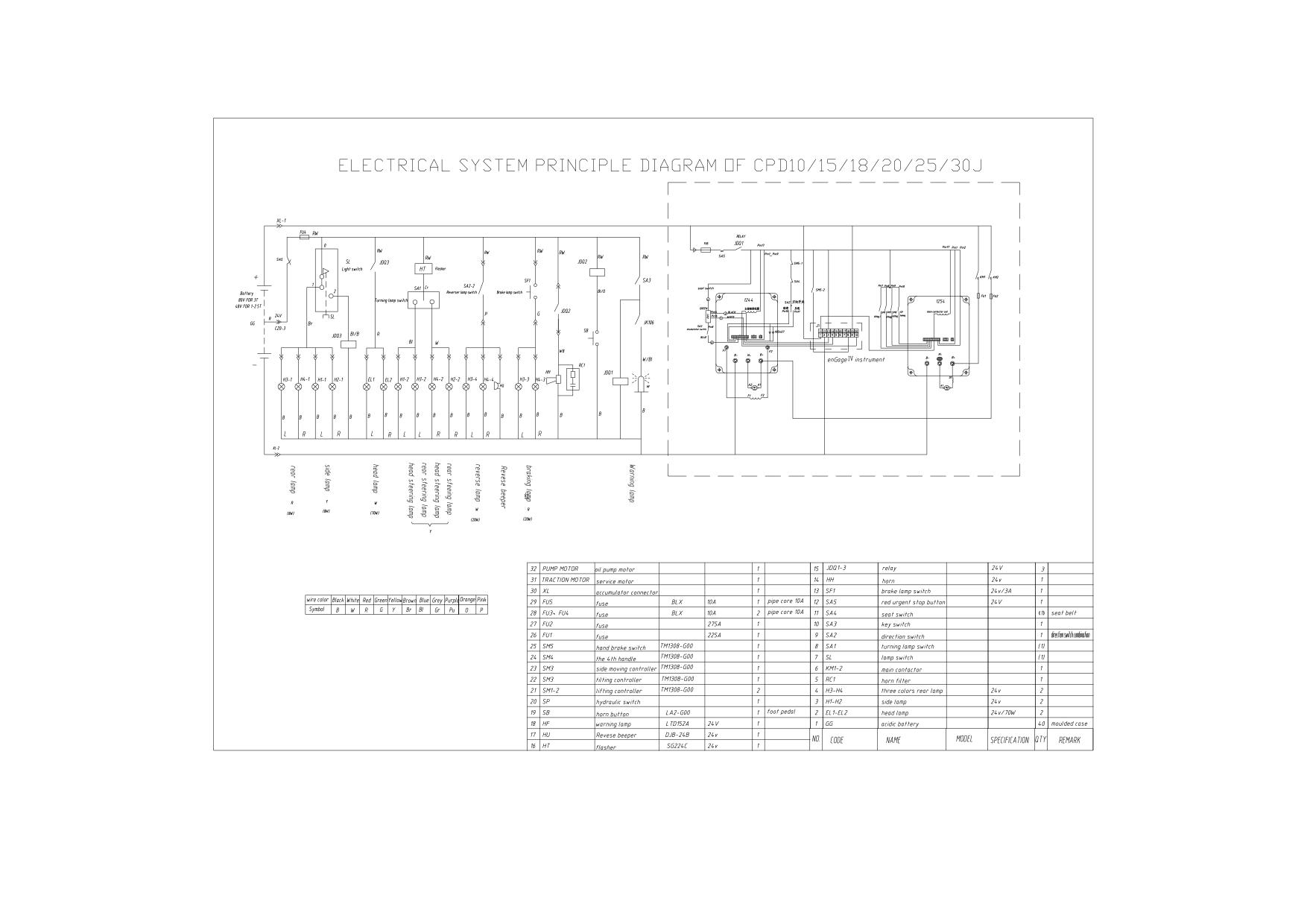
51
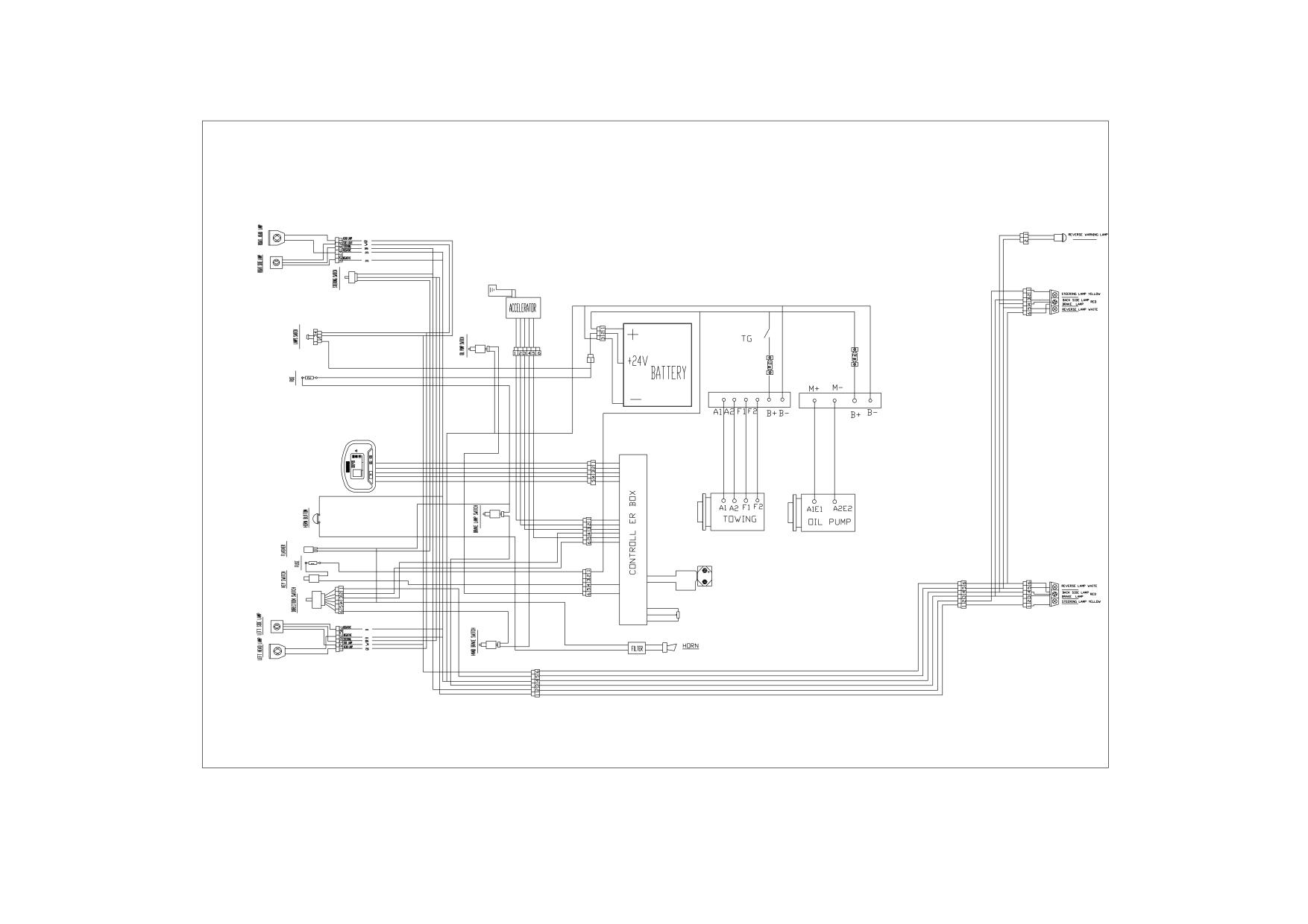
WIRING DIAGRAM OF CPD10/15/18/20/25/30J
52
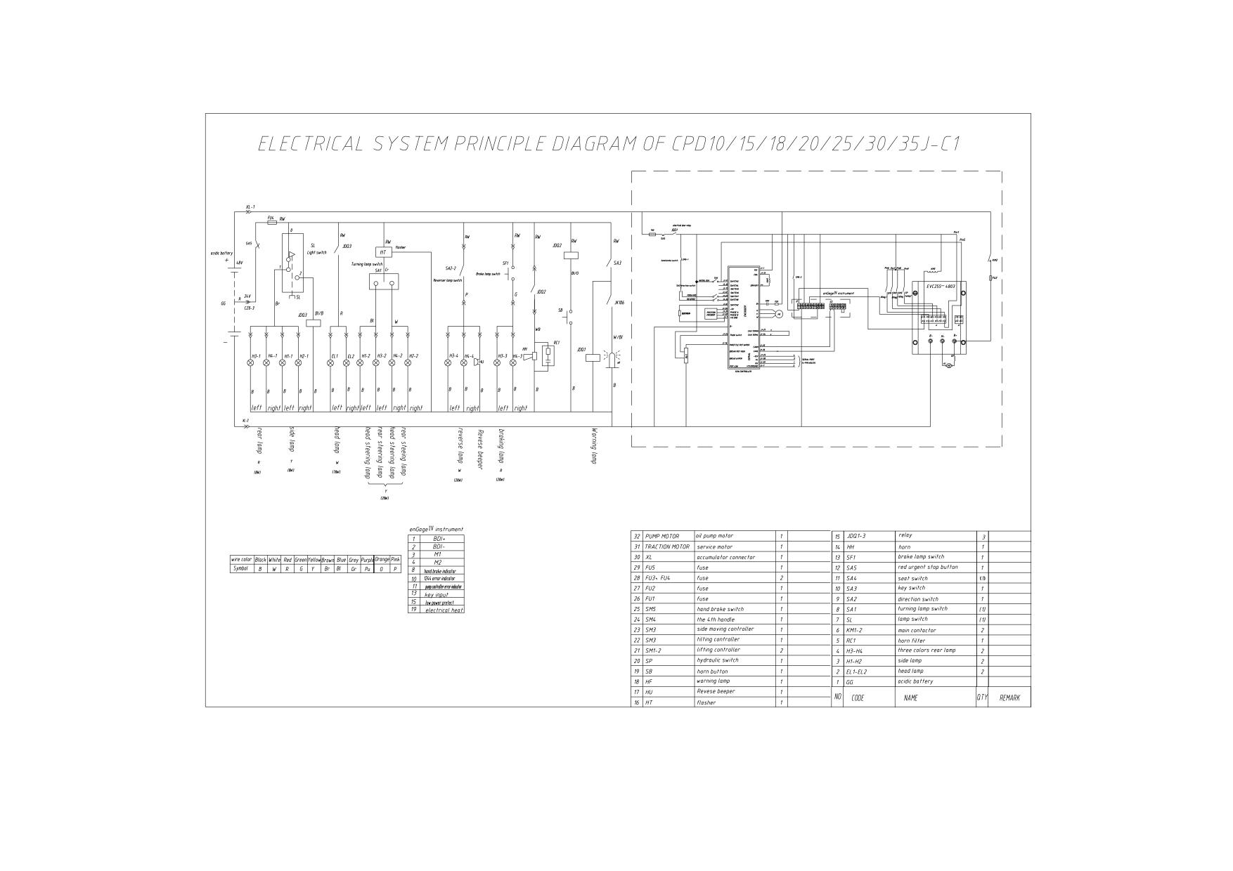
53
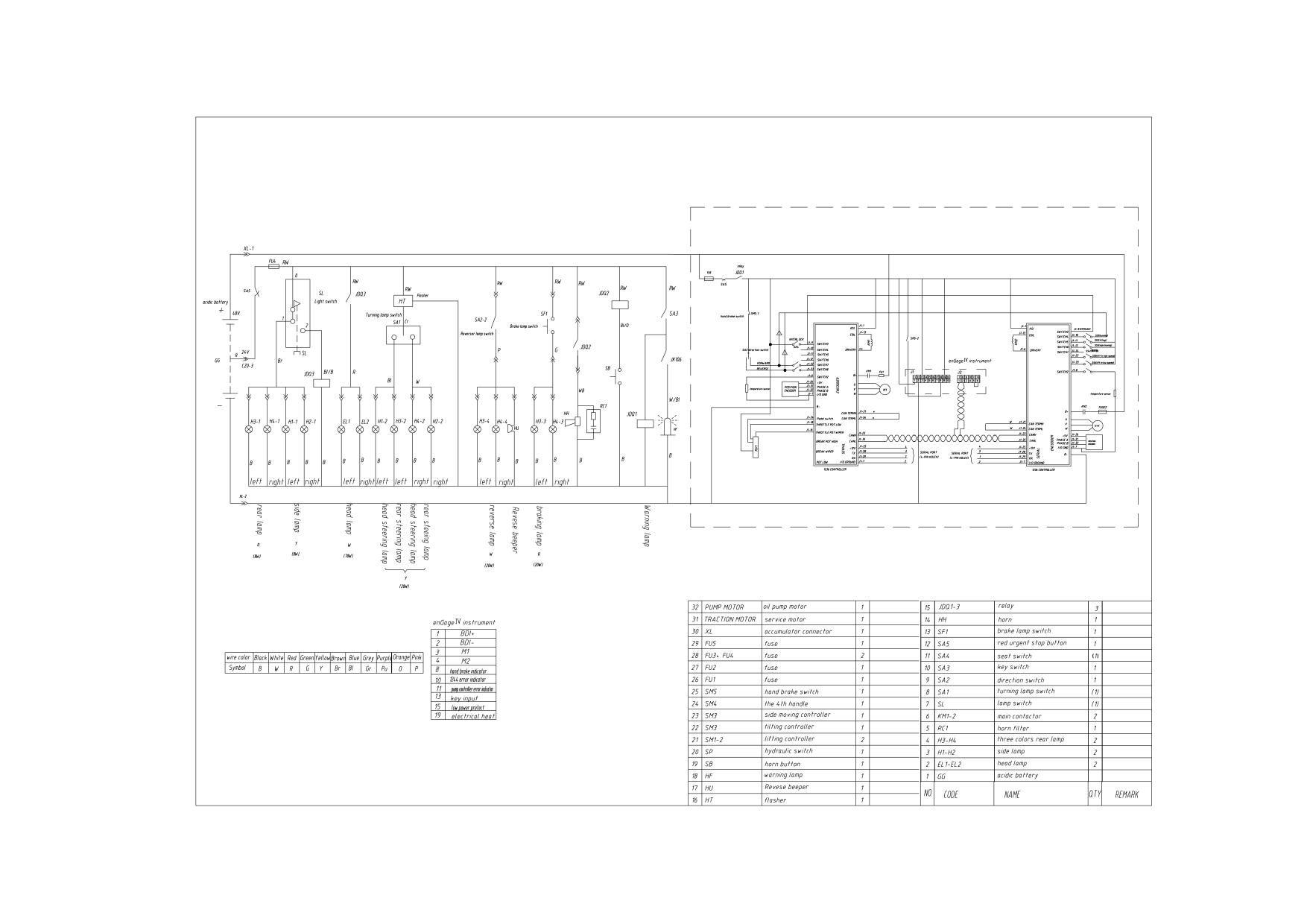
ELECTRICAL SYSTEM PRINCIPLE DIAGRAM OF CPD10/15/18/20/25/30/40/45/50J C2
54
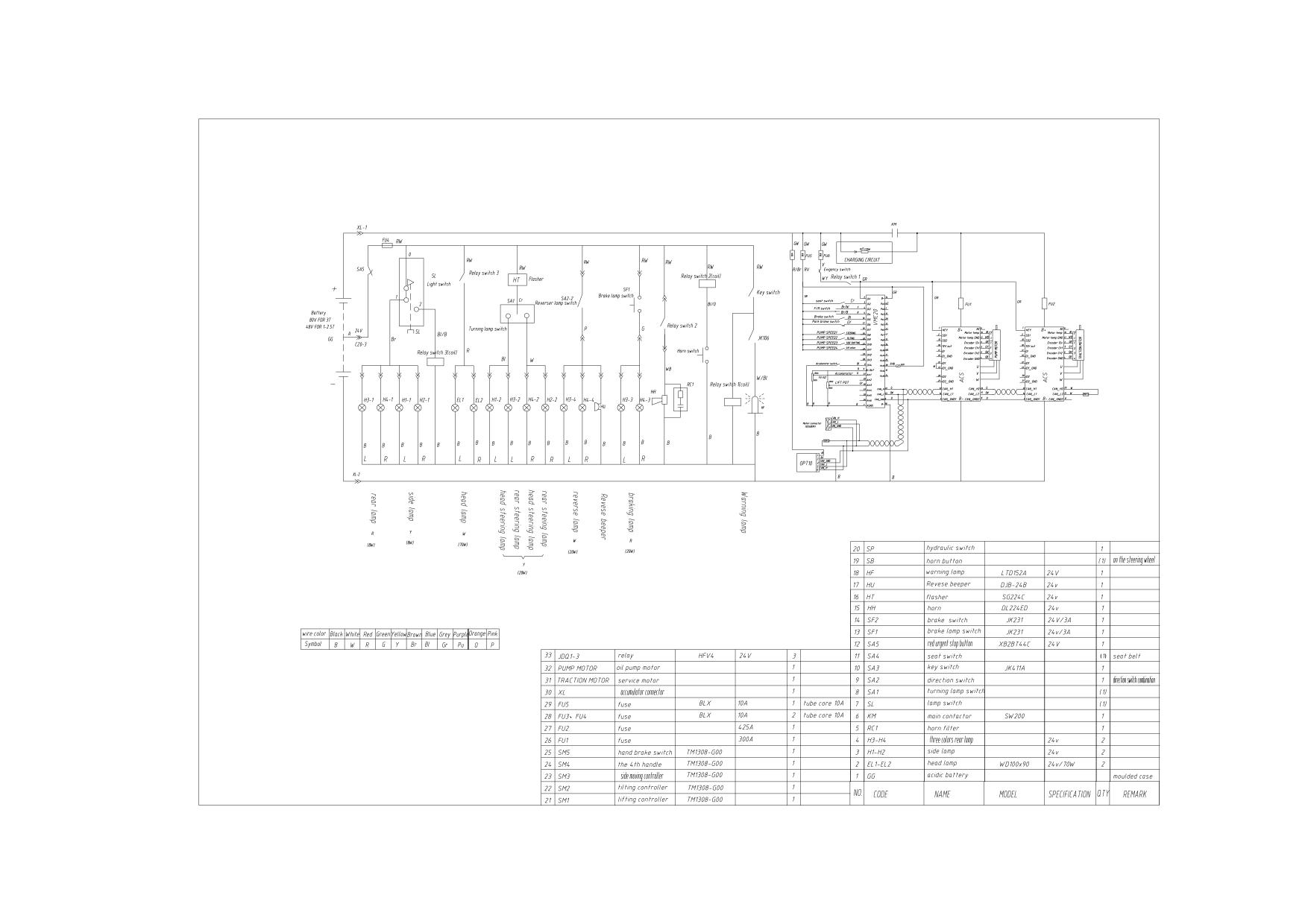
ELECTRICAL SYSTEM PRINCIPLE DIAGRAM OF CPD10/15/18/20/25/30/40/45/50J D1
55
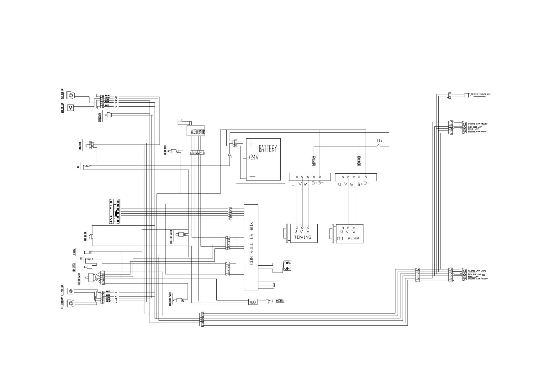
WIRING DIAGRAM OF CPD10/15/18/20/25/30/40/45/50/J D1
56

7. Maintenance record
Date
Maintain content
Maintainer
57
HANGCHA GROUP CO. , LTD.
■ Address for: OVERSEAS USERS
■ Manufacturing site: 88 Donghuan Road, LinAn Econimic Development zone,
Zhejiang, P.R.China
■ ZIP:311305
■ Registered Address:398 Shi Qiao Road, Hangzhou, P.R. China)
■ ZIP :310004
■ Fax: 0086-571-88926789,0086-571-88132890
■ E-mail: sales@hcforklift.com
CPD10/15/18/20/25/30J
CPD10/15/18/20/25/30J D1
CPD10/15/18/20/25/30/35J C1
CPD10/15/18/20/25/30/35J C2
CPD40/45/50J D1
CPD40/45/50J C2
1~5t J Series Counterbalanced Battery Forklift Truck
OPERATION AND MAINTENANCE
MANUAL
Original Instruction
HANGCHA GROUP CO., LTD.
Dec. 2010 5th edition

FOREWORD
Thanks for you purchasing our J series battery forklift truck.
Four wheel counterbalanced battery forklift truck is our company‟s new product. It has the character of
small turning radius, beautiful shape, small dimensions, low gravity, good stability, superior performance.
This operation manual is the explanations that how to use 1-5tJ series forklift truck correctly. It will instruct
you how to operate safety and precautionary maintenance. To ensure safety and exert the truck‟s potential,
all the personnel that in charge of operation, maintenance and management must read this manual
thoroughly before starting work with the forklift.
As the improvements of products of our company, maybe there are some differs between this operation
manual with your forklift truck.
If you have any questions please keep touches with HANGCHA GROUP CO., LTD. sales department or
let the agents know.
Tow electric
Rise electric
Rated capacity(t)/
Truck model
control
control
load centre distance(mm)
CPD10/15/18/20/25/30J
1244(CURTIS)
EVC255(CURTIS)
1.0/500,1.5/500,1.8/500,2.0/500,
2.5/500,3/500
CPD10/15/18/20/25/30J D1
ACS(Danaher)
ACS((Danaher)
1.0/500,1.5/500,1.8/500,2.0/500,
CPD10/15/18/20/25/30/35J C1
1238(CURTIS)
EVC255(CURTIS)
2.5/500,3/500,3.5/300
1.0/500,1.5/500,1.8/500,2.0/500,
CPD10/15/18/20/25/30/35J C2
1238(CURTIS)
1236(CURTIS)
2.5/500,3/500,3.5/300
CPD40/45/50J D1
ACS(Danaher)
ACS(Danaher)
4.0/500,4.5/500,5.0/500
CPD40/45/50J C2
1238(CURTIS)
1238(CURTIS)
4.0/500,4.5/500,5.0/500
©Dec. 2010 5th edition HANGCHA GROUP CO., LTD.
CONTENT
Foreword
1. Name of main parts or component
1
2.Instrument and Controls
2
Meter Panel
3
Controls
8
3.Body and Others
10
4.Safety instructions
12
5.The structure and stability of truck
17
6.Running-in of the new truck
20
7.Daily maintenance
21
8.Driving and operation
25
Driving
25
Traveling
25
Turning
25
Stopping or parking
26
Loading
26
Stacking load
27
Un-stacking load
27
Check after operation
28
9.Deposit
29
10.Storage battery
30
The Automatic Watering System of the Forklift Battery
38
11.Maintenance summarization
42
Preventive maintenance schedule
43
Replace the key safe parts termly
49
Table for bolt‟s tight torque
50
Table for oil used in the truck
50
12.Truck‟s convey, lifting, towing
51
13.Parameters
52
14.Scutcheon
61
15.The use, assembly and safe rules of attachment
66
16.Related safety instruction and standard
68
17.Maintenance record
70
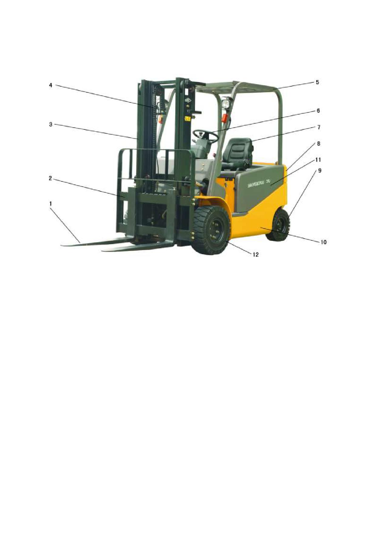
1. Name of main parts or component
1. Fork
2. Fork carriage
3. Mast
4.Lifting cylinder
5. Overhead guard
6.Steering wheel
7. Seat
8. Counterbalance
11. Left and Right battery
9. Rear wheel
10. Chassis
12. Front wheel
cover hood
1
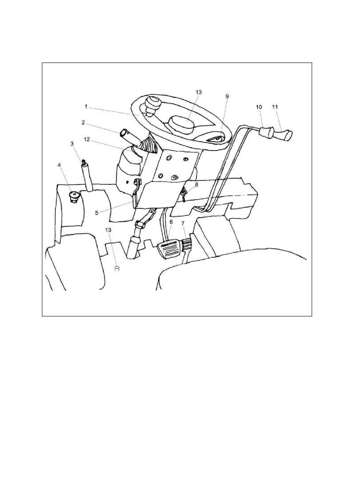
2.Instrument and Controls
1. Steering wheel
2. Direction switches
3. Parking brake lever
4.Emergency disconnect switch
5. Adjusting lever
6. Brake pedal
7. Accelerator
8. Key switch
9.Turning signal switch
10. Lifting lever
11. Tilting lever
12. Meter panel
13. Horn button
2
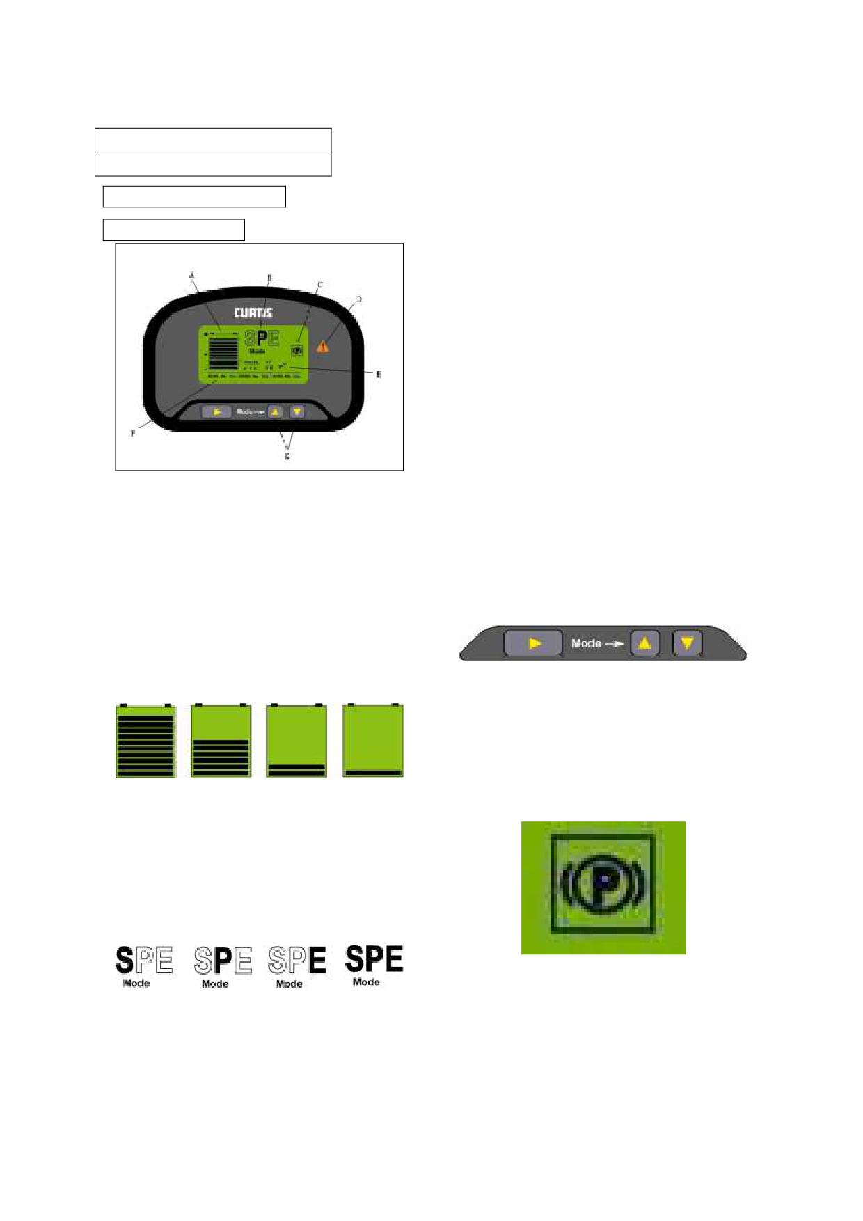
gradient and so on is much higher. It is
Meter Panel
applied for transporting mass of good in
CPD10/15/18/20/25/30/35JC1
short time and climbing big gradient slop,
CPD10/15/18/20/25/30/35JC2
but it costs more energy,so the mode will not be
used in normal state except emergency.
CPD10/15/18/20/25/30J
Mode P is power mode. All kinds of
CPD40/45/50J C2
index are lower than that of super mode. It is
applied for the case of long distance
transporting and needing higher power or
speed.
Mode E is economical mode. All the
parameters are optimized. Working in this
mode can save power so it is applied for a
long time work after charging, and it is
suggested to work in this mode in normal
work-time.
Mode SPE is safe mode. Thus the max
vehicle speed is limited to about 7km/h. It is
applied for working in busy storage and
cabined room.
A、Battery warning
Notice: the default mode is mode E. after
As the following diagram shows, from
power cutting every time, the work mode
the left to the right, the battery decreases
resets to mode E no matter which mode it is
from full state to the only one case, which
before power cutting, but the switch key is
represents that the battery leaves only 20%.
still in the mode before turn off.
Thus the whole battery indicator bar will
twinkle, and the state indicator lamp will be
bright, now please stop working and charge
immediately.
The mode can be switched through the
mode switch button (G) among the mode of
S, P, E, SPE, as the above diagram shows.
C、Parking brake indicator lamp
Notice:Charging in time is very important,
otherwise it will affect the lift-span of
battery!
B、Mode indication
When using the parking brake, the lamp will
As the diagram shows, the pictures
be bright.
from the left to the right represent the mode
of S, P, E, SPE respectively;
Mode S is super mode, thus the truck‟s
D、State indicator lamp
acceleration, deceleration rate, max climbing
3
When there is something wrong with
the electrical controller, or operate
improperly, the battery is in lower power,
the lamp will be bright and twinkles.
E、Error code display area
Display the error code of electrical
controller.
Notice:“TRAVEL” is the error code of tow
electrical controller, “HYD” is the error
code of pump controller. “TRAVEL OK”
means it works without error。
Notice: the error code of tow electrical
controller refers to the appendix.
F、Work-time accumulate timer
When the truck key switch turns on, the
left hour timer will start to time. The
minimal resolution is 10% of an hour, the
other two hour timers are not used.
4
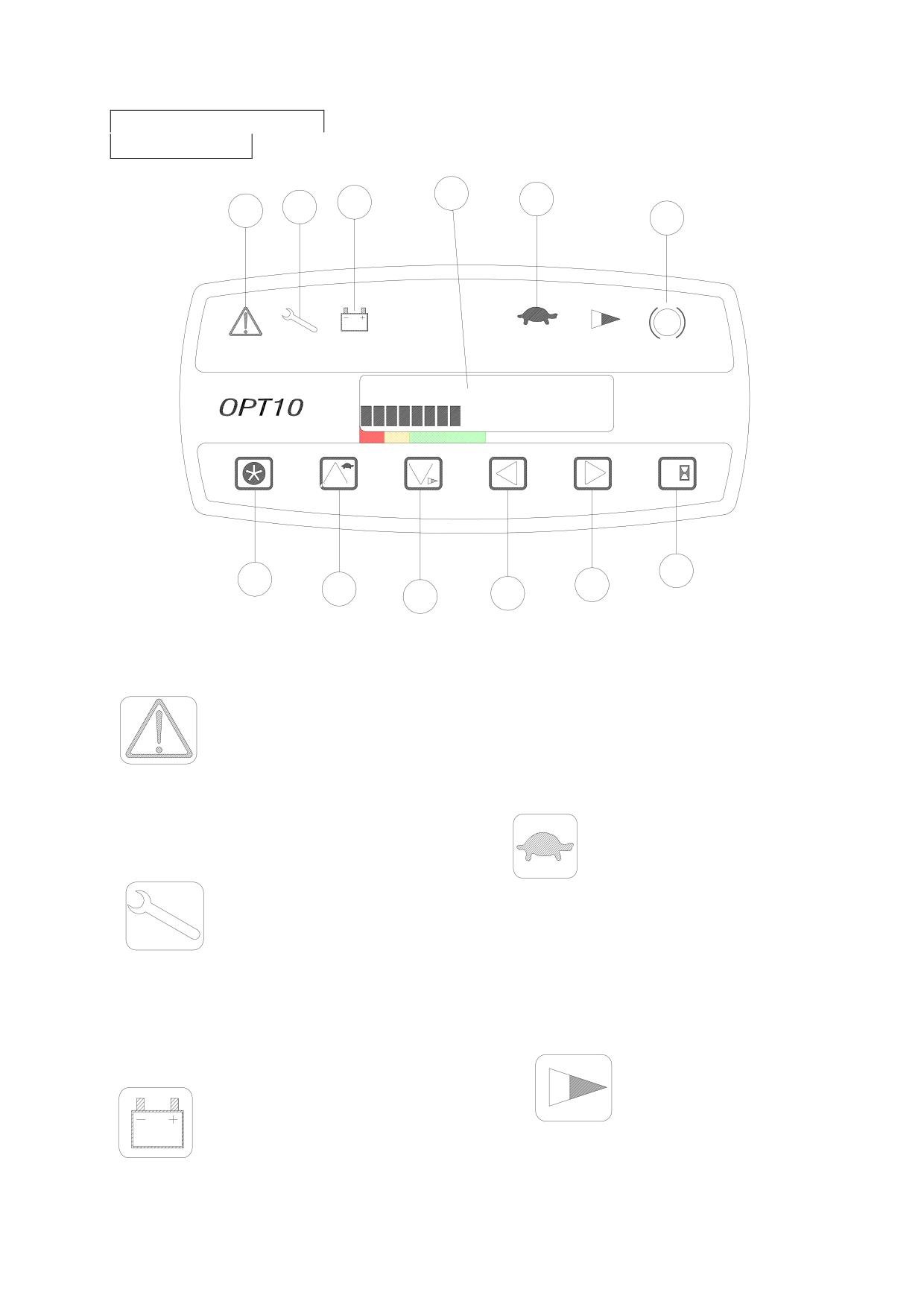
CPD10/15/20/25/30/35J D1
M
C
D
A
B
F
P
SPEED
12
km/h
BAT%
80
1
2
3
4
5
L
G
K
H
I
J
Low battery warning (C)
When battery quantity is lower than 20%
of maximum capacity, the indicator lights
are on, at the same time, buzzer beep.
When LED shows no power, please
k as possible.
Communicate indicator (A)
m,
Speed limited indicator
(D)
When this lamp lights, it meanings the
truck working at low speed mode. The
maximum speed of truck decreased.
Error indicator (B)
Press button 1, you can switch the high
e.
When operation is wrong or the truck is
will display on the
ndicator lights on.
5
Accelerate indicator (E)
)
When this lamp lights
o use for operator.
truck working at low ac
The maximum acceler
y
ou can
4
low acc
P
operator
Parking brake indicator (F)
When pulling on the parking brake le
5
KE
Y
O
N
T IME
28H
B A
T%
8
0
1
TR
A
CT TIM
E
18
H
Speed limited button (H)
B
AT
%
8
0
tch the high speed
Push the button once again, it switch to
speed display mode.
Dashboard display LED (M)
2
When turn on the key switch, the system
will self-diagnose, the lamp will lights on
one by one. After self-diagnose, LED
will display truck speed and battery
capacity. You can know your truck‟s
working condition through the LED
dashboard.
Key switch
3
The key switch has two “on/ off”
position, you should push the Direction
switch lever to neutral and loose the
accelerator pedal, then turning the key
switch to “on” position clockwise.
6
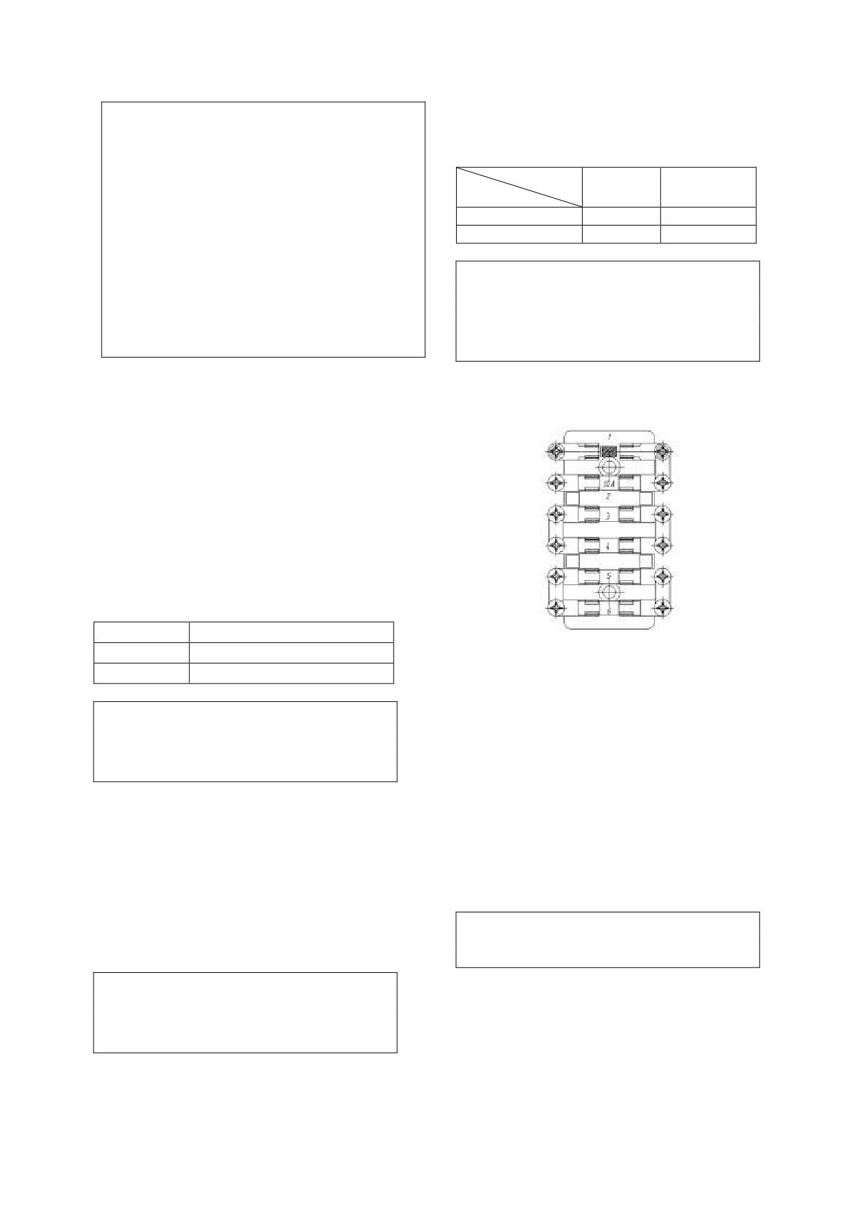
Caution!
Rear big lamp switch (optional)
1. Turning the key switch “on” does not
Rear big lamp switch (push\pull) has
make the forklift truck move, if the
only one shift.
Direction switch lever is not in the neutral
Connector
battery
Far light
position or the accelerator pedal is pushing.
Position
2. Error code maybe appear, don‟t worry
0
×
about it.
1
×
×
3. The Direction switch lever should be
× Means connected
returned to neutral and move you foot from
Caution!
the accelerator pedal. Then the truck can be
This light does not relate to key switch
operated.
position, so please don‟t forget to turn off
4.
Then the error code should be
the rear big lamp when you leave the
disappeared.
truck.
Horn button [13]
Fuse box
Press the rubber cover at the center of
J\JC1\JC2 Series
steering wheel to sound horn. The horn
sounds even when the key switch is in
the “off” position.
Combined light switch [9]
This combined light switch is composed
of turning light switch and big/small
lamp switch. Turning light indicates the
traveling direction. When turn on the
switch, the lamp flashes.
Forward
Left turning lamp flashes
Neutral
Lamp goes off
1st is a diode preventing from connecting
Backward
Right turning lamp flashes
in reverse.
2nd is a control circuit fuse (10A).
Caution!
3rd and 4th are fuses for light and horn
The turn signal lever does not
circuit. (10A respectively)
automatically return to the neutral
5th is light fuse 10A.
position. Reset it by your hand.
6th is spare fuse 10A.
Big/small lamp switch has two shifts.
JD1 系列
First shift small lamp lights on; second
1st is control circuit10A.
shift big and small lamp both light up.
2nd is main contact circuit fuse 10A.
Emergency disconnect switch [4]
3rd is instrument fuse 10A.
4th and 5th is light fuse 10A.
When happen emergency, presses down
6th is spare fuse 10A.
the emergency disconnect switch, and
then the main power of the truck will be
Caution!
When replace a new fuse, please choose the
cut off, the truck stops working.
same capacity fuse of the old one.
Caution!
Please don‟t use the emergency
disconnect switch to substitute the
function of key switch.
7
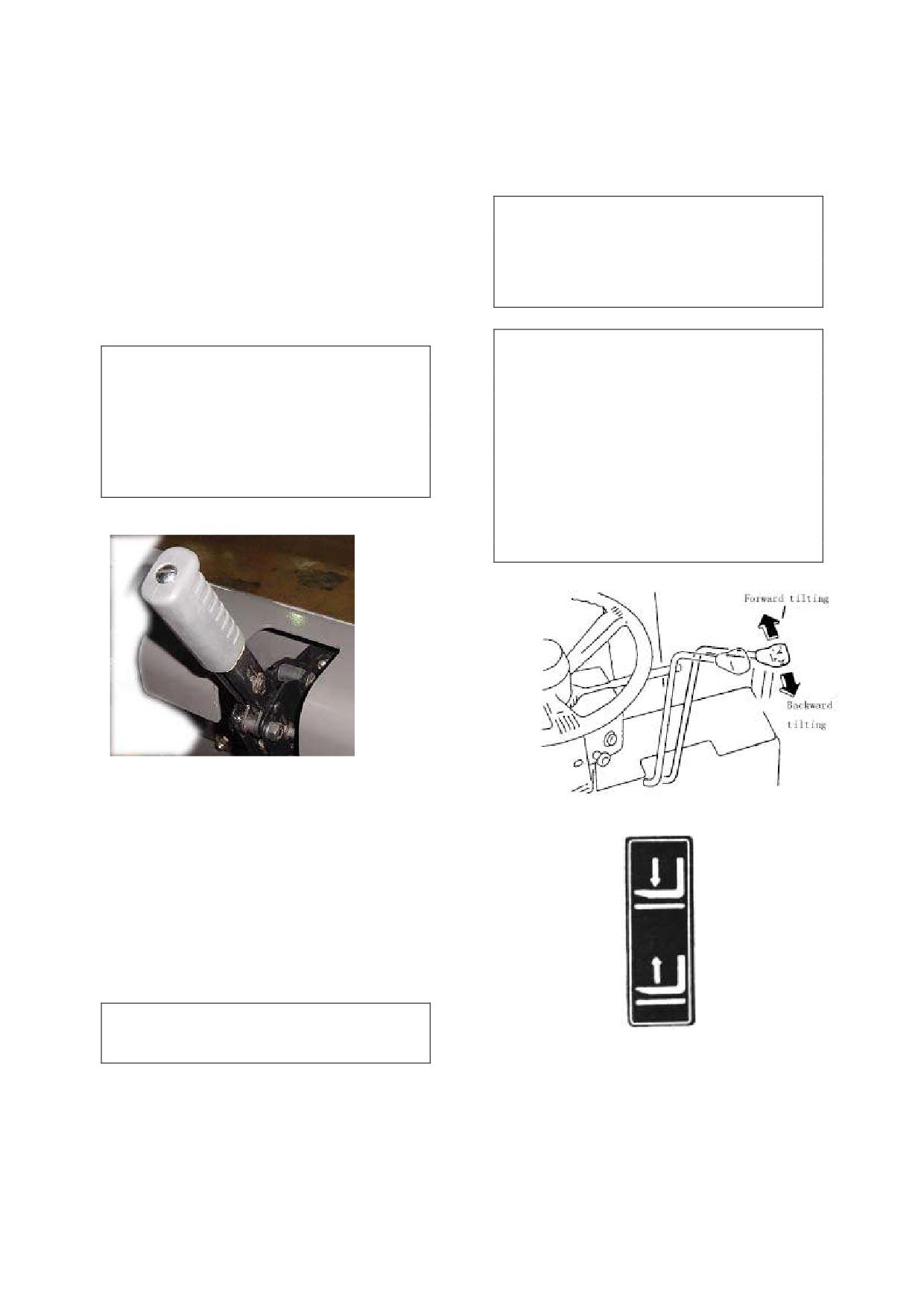
pressed, the forklift trucks moved
Controls
forward. When the lever is pushed
Steering wheel [1]
backward, the forklift trucks moved
The steering hand-wheel is operated
backward.
in the conventional manner, that is, when
Caution!
the wheel is turn right, the truck will turn
While traveling, if change the
to the right; when the wheel is turn left,
Forward- Reverse lever, electric braking
the truck will turn to the left. The steer
will operate,speed will lower until stop,
wheels are located at the rear of the truck.
then travel to the opposite direction.
These cause the rear of the truck to swing
out when a turn is made.
Warning!
Warning!
Turning the key switch “on” does not
This truck is provided with the
make the forklift truck move, if the
power steering, so heavy hand-wheel
Forward-Reverse lever is not in the
operation is caused when the steering
neutral position or the accelerator pedal
motor comes to a stall. To put the power
is being pressed. In this case, the
steering in operation again, restart the
Forward-Reverse lever should be
steering motor without delay.
returned to neutral and move you foot
from the accelerator pedal. Then the
Parking brake lever [3]
truck can be operated.
Use this parking brake lever to park
the lift truck. And the parking brakes are
applied on the front two wheels by
Lifting lever [10]
pulling up on this lever. To release the
parking brakes, move the lever forwards.
There is a micro switch at the left
side of the parking brake lever, tense the
lever makes running invalid.
For the truck of CE: if you leave the seat
without tensing the lever, it will warn and
remind you to tense the lever.
Warning!
If parking on a grade is unavoidable, be sure to
block the wheel.
The forks can be raised or fell by
Forward-reverse lever [2]
pulling backwards or pushing the lever.
Lifting speed can be controlled by tilt
The forward-reverse lever is used for
backwards angle of lever and the
switching
between forward
and
lowering speed can be controlled by tilt
backward moves. When the lever is
forwards angle of the lever.
pushed forward and accelerator pedal
8

Tilting lever [11]
Caution!
Loosen the accelerator pedal when truck
is working, truck can make soft brake
The mast can be tilted by operation
of this tilt lever. Pulling on this lever
backwards will tilt the mast backwards,
and pushing it forwards will tilt the mast
forwards. The tilt speed can be controlled
by tilt angle of the lever.
Caution!
The tilt lock mechanism built in the
hydraulic control valve does not allow
the mast to tilt forwards while the
electricity is being shut down even if the
tilt lever is pushed forwards.
Pedals
Brake pedal [6]
Press this pedal to slow or stop the
truck. At the same time, the brake light
comes on.
Caution!
No permitted to press the brake pedal and
the accelerator pedal at same time,
otherwise, it is harmful to the traveling
motor.
Accelerator pedal [7]
As the accelerator pedal is slowly
pressed, the drive motor start turning and
the forklift truck will start to move.
According to the force applied to the
pedal, the speed is adjusted with not
steps.
Warning!
Before open the key switch to press
the accelerator pedal, the more function
digital indicator shall show alarm
information. Then you must release the
accelerator pedal.
9
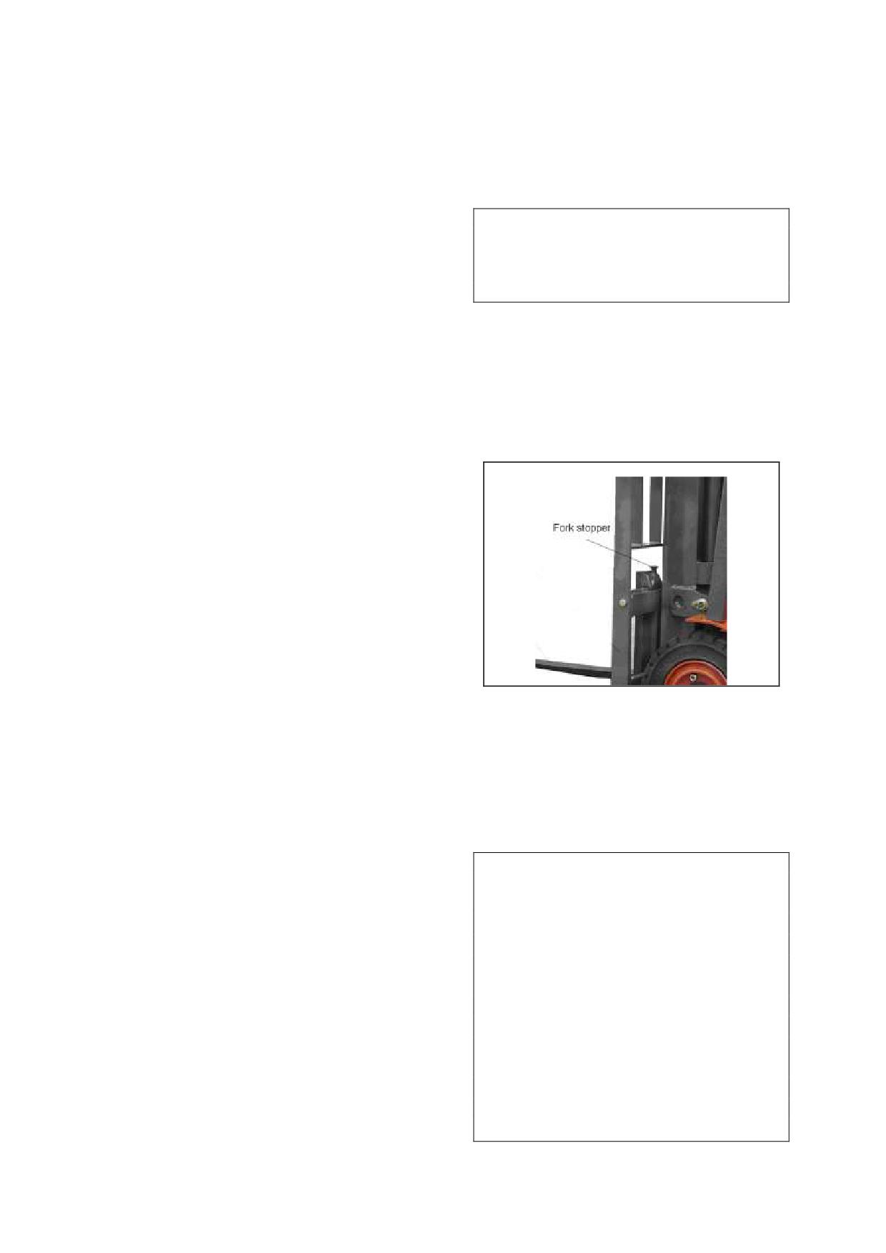
the storage batteries.
3.Body and Others
You can lift up the hood with little
Seat
effort with an aid of hood damper. To
Adjust operator‟ seat to the position
lock the hood, push down on the front of
hood until it covered.
where is comfortable for you and
provides
easy
controls.
Before
Caution!
Be careful do not to catch you fingers in
proceeding with work, adjust operator‟s
the hood when closing it.
seat and make sure that it is securely
Depress the spring insurance before you close
locked. Adjust the operator‟ weight
the hood, then press the head of the hood.
through rock- suspends system level. The
rear of the seat is adjustable.
Left & Right battery cover hood
Seat switch (only for trucks exporting
The battery is covered hood, one left
to Europe or option)
and one right. When you want to take off
For the safe of truck, when you leave
the hood, you should take off the knob at
the seat longer than 5 seconds, the truck
first.
will stop traveling.
Fork stopper
Safety belt
Please keep back and waist close to
seat as far as possible, and fix safety belt
at the same time.
Inspect whether bolts fixed belt are
loose or not. Do not use belt with a knot.
Do not make belt press on stiff or fragile
things, and do not make belt attrite with
sharp things to avoid wearing. Do not
make seat backrest too be tilted;
otherwise safety belt may not extend
correctly.
Do not remove any part of belt at
will. Please often inspect the belt used
Fork stoppers are locked the forks in
frequently, if found any abnormal,
position. To adjust fork spacing, pull up
replace it at once. And the life for use is
fork stoppers, turn 90°and shift the forks
3-5 years, scrap it ahead of schedule if
to the desired position. The fork spacing
found any abnormal.
should be adjusting according to loads to
There is a safety belt on the seat,
be handled.
before you operate the forklift truck,
please fasten the seat belt to protect
Warning!
yourself.
The forks should
be
set
Overhead safe guard
symmetrically to machine centerline and
The overhead guard used is strong
fork stoppers should always be locked
enough to meet safety standard, and
again.
protects the operator from falling
There are one gap on the below
materials. The top gap is used to lift the
beam. It is used to attach goods.
batteries. It is forbidden for use a truck
It is forbidden to lock the fork on the gap
that does not with safeguard.
position, to prevent the fork fall off from
the gap.
In the middle of the above beam, a
Hood
bolt used to prevent fork works here.
The hood can be swung up fully to
Please change the bolt as soon as it is
provide easy examining and maintenance of
damaged.
10
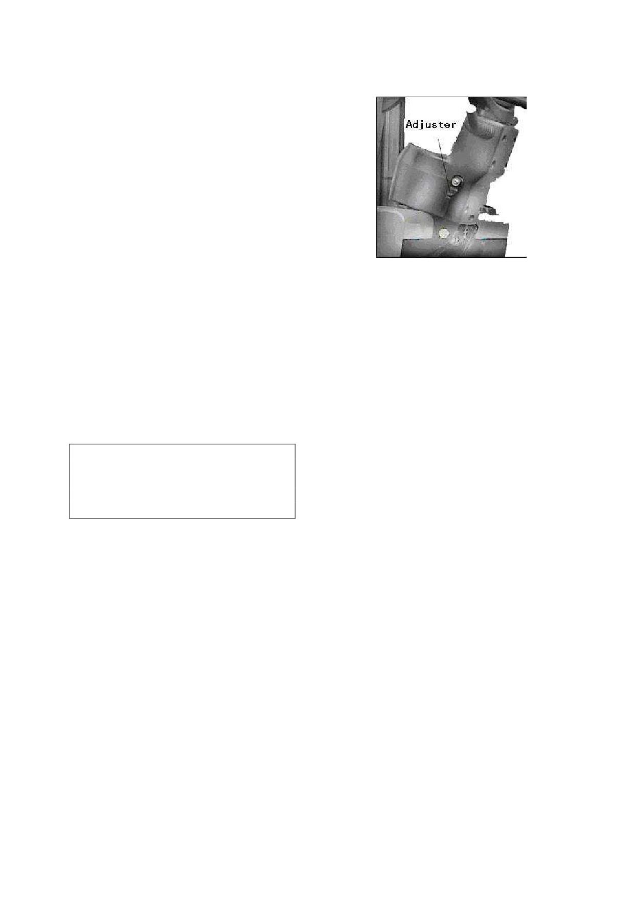
Change fork
Steering column tilting angle adjuster
Take down the old fork: Firstly,
locate the fork to the middle, decline it to
the ground and make the mast forward,
then operate the truck traveling backward,
the fork will be taken down.
Change new fork: Firstly, make the
fork dead against the truck and forklift‟s
mast to the bottom, then operate the truck
traveling forward, aim at the two gaps
and beams, and raise the mast. Adjust the
position of the fork.
Safety step and safety grip
The tilting angle of the steering
The safely steps are provided on
column is adjustable to suit individual
both side of the truck body. The safely
operators. Turn the hand lever upward to
grip is provided on the front left pillar of
release the steering column and locked
the overhead guard. Use the safely step
by turning it downward.
and safely grip when mounting and
Hydraulic oil reservoir cap
dismounting the truck.
The hydraulic oil reservoir cap is
Brake fluid reservoir cup
located at the right rear end, below the
The brake fluid reservoir cup is
battery hood; open the right side battery
located at the meter board.
hood when adding oil. After fill in clean
hydraulic fluid, tighten lock the cap.
Caution!
Air leakage plug
The brake fluid is poisonous, be
careful do not drop down. When add
There is an air leakage plug on the
brake fluid, be careful do not let dirt and
oil tank to let air in the tank goes out.
other thing drop into reservoir cup.
You‟d better often check the plug and see
whether been jammed.
Chair disconnecting switch
Head lights and combination lights
When the operator leaves seat, this
Two headlights and combination
switch cut off, and the power of truck is
lights (turn signal, show width lamp) are
cut off.
installed at the front side of the truck.
Take care of the lights, and wipe dirt, if
Safety seat belt (for the trucks
any, and replace any damaged light
exporting to Europe or option)
immediately.
There is a safety belt on the seat,
Rear combination lights
before you operate the forklift truck,
please fasten the seat belt to protect
The combination lights at the rear
yourself.
side serve as turn signal, show width
lamp, brake lamp, and back-up lamp. Pay
Rear big lamp (for the trucks
attention to keep them from being
exporting to Europe or option)
damaged or covered with dust, if any,
The rear big lamp is set on the
clean or replace immediately.
safeguard. If it is broken, please replace a
new one at once.
11
4.Safety instructions
1. Only trained and authorized
operator shall be permitted to operate the
truck.
4. Operator must wear helmet, safety
shoes and work clothes.
5.
Because there will bring
exploding gas in the bosom of the battery,
2. Inspect the truck at periodic
prohibit any flame nearby it absolutely.
intervals for oil or water leak,
·Do not let any tools close the two
deformation, lousiness, etc. If neglected,
terminal of the battery to avoid spark or
short life of components will be caused
short circuit.
and in the worst case a fatal accident
6. The movement road of forklift
would occur.
should be solid and smooth coagulation
·make sure having replaced good
road or similar to the road suitable for
parts during periodic check.
vehicle. Recheck the state of working
·Wipe off oil, grease or water from the
ground.
floor board and foot and hand controls, if
The considered climatic conditions
any.
when the forklift designs are:
Strictly prohibit smoking and spark
Temperature
-
20℃-50℃; the wind
nearby the storage battery when checking
speed does not surpass 5m/s; the air
it.
relative humidity is not bigger than 90%
·If maintenance on high position,
(temperature 20℃). The forklift is not
such as mast, front and rear lamp, please
suitable in the flammable explosive
be careful to prevent fall down or be
working conditions.
clamped.
7. Never mount or dismount the
·Be careful do not be scalded when
moving truck. Use the safety step(s) and
inspect the motor, controller and etc.
safety grip facing the truck when
3
whatsoever in trouble, you must
mounting or dismounting the truck.
stop the forklift, hang a mark of “danger”
or “trouble” and take off the key, at the
same time inform the manager. Only
after the trouble is removed, you may use
the forklift.
If trouble occurs when lifting cargo,
to Climb or descend, or the storage
battery electrolyte, the hydraulic fluid,
the brake fluid has the revelation, please
organizes the personnel to repair
immediately.
12
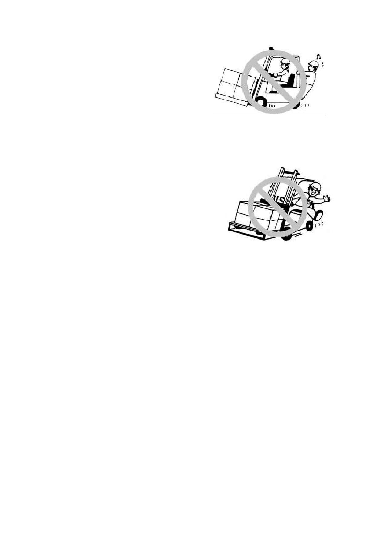
8. Never attempt to work the
controls unless properly seated.
Before starting, adjust the seat so
you can get easy access to all hand and
foot control.
9. Before starting up, make sure that:
Please fasten seat bolts.
The parking brake lever is applied
securely.
15. Keep your mind on your work.
The forward-reverse lever is in
16. Keep your head, hands, arms,
neutral.
feet and legs within the confines of the
·Before staring, make sure no one is
operator‟s compartment. Never stretch
under, on and close to the truck.
out for any reason.
·Don‟t step the accelerate pedal or
control the lifting lever or tilting lever
before turning on power.
10. Operate the controls smoothly.
Avoid sudden stops or turns.
·It is dangerous to make a sharp
brake. Otherwise the truck has the
possibility of overturn.
11. Pay attention to the route of the
truck; be sure to make a wide sight.
12. Never allow other person(s) to
ride on the forks, pallets or on the truck.
17. The pallet and skid used should
13. Taking account of the shape and
be strong enough to endure the load.
material of loads to be handled, use a
Never use damaged or deformed ones.
proper attachment and tools.
18. We afford all type of attachment,
·Avoid hoisting the load, with wire
such as rotating roll clamp, bale clamp,
rope hung on the forks or attachment,
side shifter, and crane jib etc. You should
since the wire rope may slide off. If
refit the truck under ours license if you
needed, a qualified personnel for slinging
want. It is forbidden to refit it by
operation should perform, making use of
yourself.
a hook or crane arm attachment.
19. Safeguard protect you do not be
Take care not to protrude the forks
hurt by the goods fallen. Load bracket
out of the load. The protruded fork tips
protect you load goods smoothly. It is
may damage or turn over the adjacent
forbidden to use truck without safeguard
load.
or load bracket.
14. Know the rated capacity of your
20. It is forbidden to walk down the
lift truck and its attachment, if any, and
fork or the attachment.
never exceed it.
It is forbidden to walk up the fork or
·Do not use a man as an additional
stand on the fork.
counterweight. It‟s quite dangerous.
13
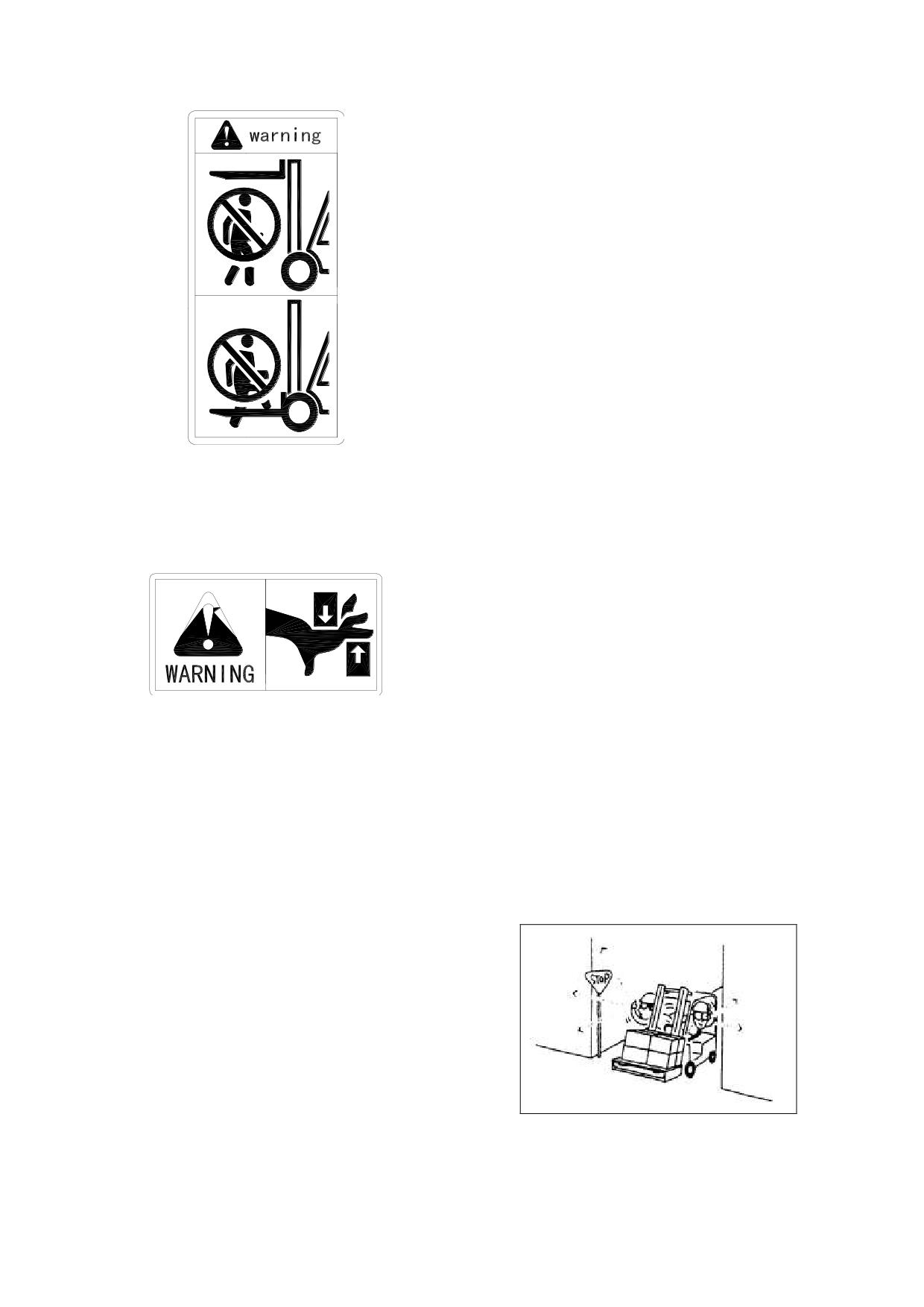
reverse tilt
when stacking and
un-stacking loads. Never tilt forward
unless load is over stack or at low lift
height.
·When stacking loads on a high
place, once make the mast vertical at a
height of 15 to 20 cm above the ground
and then lift the load farther. Never
attempt to tilt the mast beyond vertical
when the load is raised high.
To un-stack loads from a high place,
insert forks into the pallet and drive
backwards, then lower the load. Tilt the
mast backwards after lowering. Never
attempt to tilt the mast with the load
raised high.
21. It is forbidden to put your hands,
arms or head stretch between the mast
25. It is dangerous to travel with
and safeguard. Once clamped, the life
forks higher than appropriate position
has danger.
regardless of whether loaded or not.
It is forbidden to put your hands in
Keep the good traveling posture. (When
inner and outer mast.
traveling, the forks should be 15 to 30 cm
above the ground or floor and the mast
tilted backward)
·Do not operate the side shift
mechanism, if equipped, when the forks
are raised and loaded, since this will
cause the truck to be unbalanced.
22. The goods is liable to drop
26. Watch for branches, cables,
turning or passing rough road when it
doorways, or overhangs. Pay caution
departures the center. And the forklift
when working in congested areas.
may turn over more probably.
Slow down and sound horn at cross
aisles and other locations where vision is
23. Don‟t stack loads on forks in
restricted.
such a way that the top of loads exceeds
·When make a turn, be sure the
the load backrest height. If unavoidable,
speed of the truck is lower than the 1/3
make sure the load is fastened. When
max. of allowable speed.
handling bulky loads that restrict your
vision operate the truck in reverse or
have a guide. When lead by a guide,
make sure you understand hand, flag,
whistle or other signals. When handling
long loads such as pipe, lumber etc or in
the case of the Large-sized model, or
operate with long attachment, be
extremely careful of load end swing at
corners or in narrow aisles. Be alert for
27. Affirm keeping some distance
others.
from roadside and flat roof.
24. Use minimum forward and
14
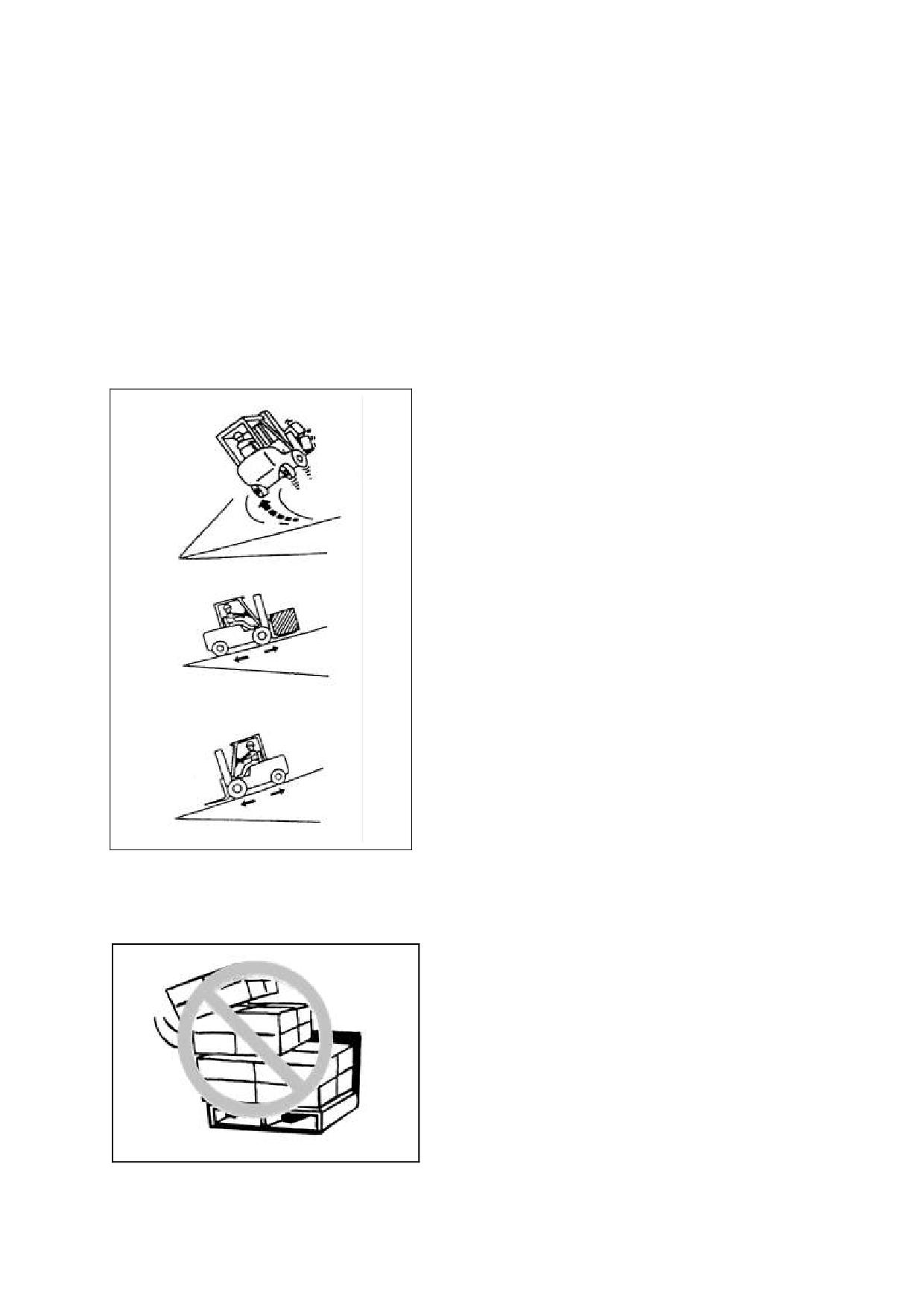
28. Before driving over a dock-board
31. Never lift loads with the truck
or bridge-plate, be sure that it is properly
inclined. Avoid loading work on a grade.
secured and strong enough to sustain the
weigh.
32. Never permit anyone to stand or
walk under upraised forks or other
29. When operating loaded truck,
attachments if machine is so equipped. If
have the rear end of your machine
unavoidable, use a safety stand or block
pointed downhill.
to prevent a possibility of fork
·When operating unloaded truck,
attachments falling down or moving
have the rear end of your machine
unexpectedly.
pointed upgrade.
Do not make a turn on the grade, in
33. Inspect the surface over which
order to avoid overturn.
you will run. Look for holes, drop-offs,
obstacles, and look for rough spots. Look
for anything that might cause you to lose
control, bog down or upset.
·Clear away trash and debris. Pick up
anything that might puncture a tire or let
the load lose balance.
Slow down for wet and slippery
roads. Stay away from the edge of the
road. If unavoidable, pay more attention.
·Do not operate the truck when the
weather is execrable, such as windy,
thunder storm, snow and etc. Especially
when wind speed is higher than 5m/s,
don‟t operate the truck outside.
34.An accumulator is required for
controller. Forbid to touch within B+ and
B- to prevent from wounding by
electricity. Before checking or cleaning,
please connect loads (contactor circuit or
horn for example) between B+ and B-
first to discharge for capacitor of
30.the goods is liable to drop turning or
controller.
passing rough road when it departures the
center. And the forklift may turn over more
35. Pulling the hand brake when
probably.
parking on flat. If necessarily parking on
ramp, you should place the wedges under
wheels.
·Descending the fork to the ground
and keeping a little forward tilting, shut
off key switch and take off key.
Pull out the battery plug.
The parking place must be far away
from fireworks.
15
36. You can tow the forklift to the
load cargo.
safe place with towing pin when the
forklift can‟t run.
43. There are enough light at truck
·Don‟t tow the truck which steering
work ground. At night, open the head
system or brake system has been
lamp to collocate enough lamp-house.
damaged.
44. Only in the event that the truck
37. There is operating method and
manufacturer is no longer in business and
warning label on the truck. Please
there is no successor in the interest to the
operate the truck obey the rules on the
business, the user may arrange for a
label and this manual. Often inspect the
modification or alteration to a powered
nameplate, when damaged or lost please
industrial truck provided, however, that
replace it.
the user shall:
a) Arrange for the modification or
38. Fire extinguisher must be
alteration to be designed, tested and
prepared at working place. Users can
implemented by an engineer(s) expert in
select fire extinguisher along with truck,
industrial trucks and their safety;
and it usually is fixed on rear supported
b) Maintain a permanent record of
leg of safety shelf, it is easy to pick.
the design, test(s) and implementation of the
Driver and manager should be
modification or alteration;
familiar with the position and operation
c) Approve and make appropriate
of fire extinguisher.
changes to the capacity plate(s), decals,
tags and instruction handbook;
39. Please use stock when conveying
d) Affix a permanent and readily
little goods, it is forbidden to use fork
visible label to the truck stating the
directly.
manner in which the truck has been
modified or altered together with the date
40.The work road surface for forklift
of the modification or alteration, and the
should be stability and unknit, cement,
name and address of theorganisation that
blacktop or beton. If there are snow, ice,
accomplished the tasks.
water or other eyewinker, bar. Eliminate
all, then work. Otherwise the truck will
be out of control and lead the safety
accident.
41. Move the truck to the place which
respects traffic when it anchors. If the
reason is brake or turn system, move it
by a suitable truck (Reference the part of
truck move); Other reasons, use a suitable
truck to traipse, tie the cord outside of
truck. Please abide by the traffic
regulations when traipse the truck on
calzada.
42. After take-down the hood, water
tank cover board, overhead, backrest of
mast, unallowed to operate the truck or
16
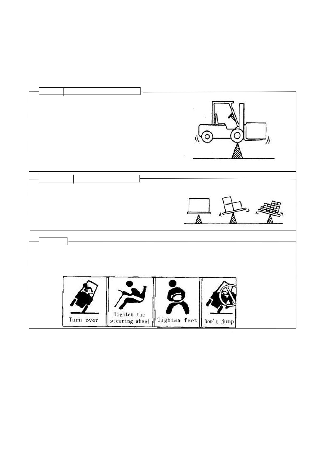
5.The structure and stability of truck(Prevent the forklift to turn
over!)
It is very important for operator to know the truck‟s structure and relationship between
load and stability.
Caution
the structure of the truck
The basic structure of the truck is mast (include mast and
forks) and body (include tire).
The lift truck keeps the balance of weight between
the truck body and the load on the forks with the center
of the front wheels as a fulcrum when the rated
capacity load is placed in position.
Due care should be paid to the gravity center of
loads and forklift to maintain the stability of the truck.
Caution
Load center
There is difference in gravity because of the loads‟
shape, such as box, board and large roller. It is very
important to distinguish the difference of the gravity
center of loads for evaluating the truck‟s stability.
Warning!
If the truck will turn over, do not attempt to get out of the truck because the speed of
overturn is much faster than your speed. You should hold the steering wheel handle, stretch
your feet, and this practice will let you in the seats. Operator fastens the safety belt please.
17
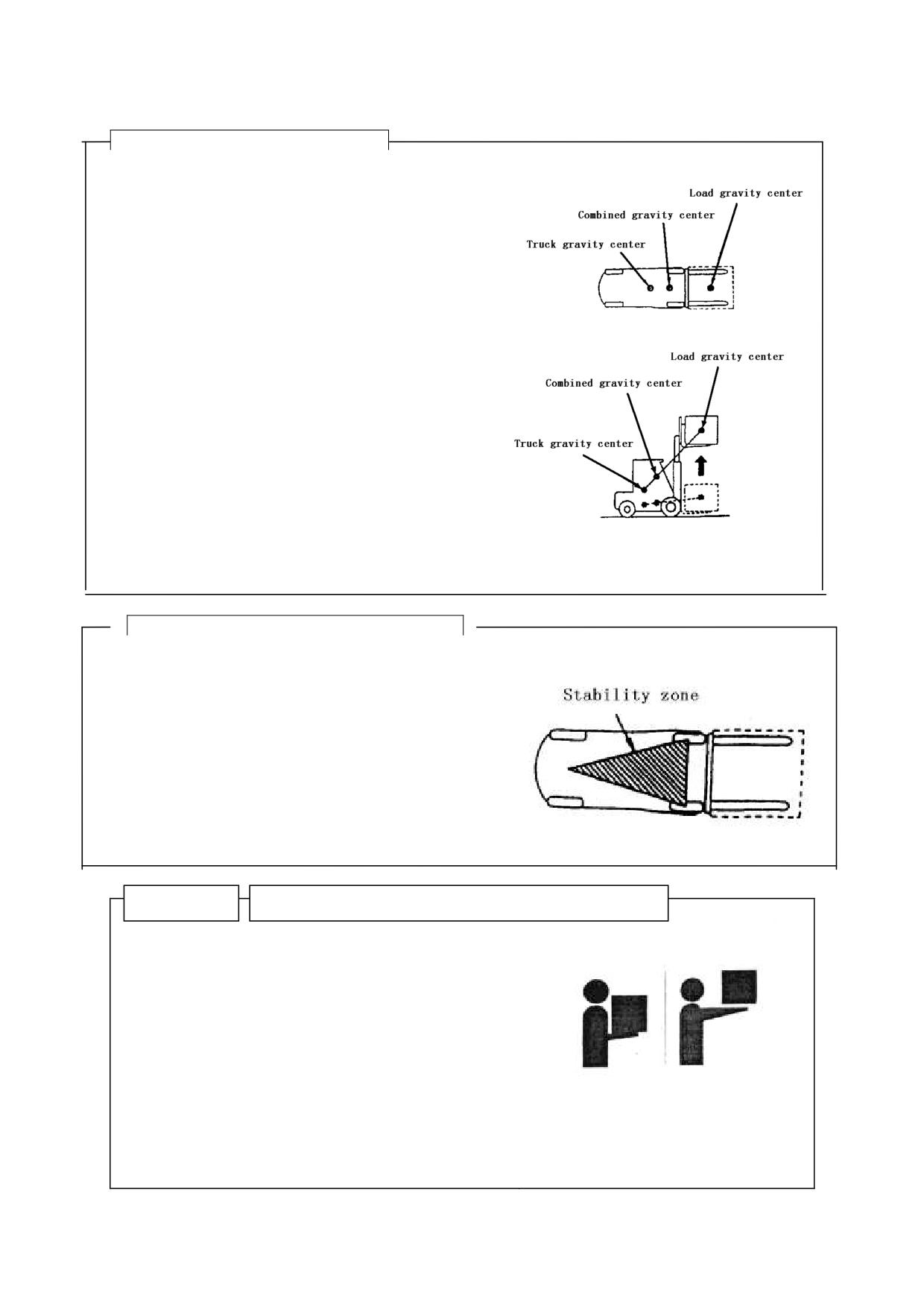
Caution Gravity center and stability
The combined gravity center that is
composed of the forklift center and the load
gravity center determine the stability of lift
trucks.
When unloaded, the barycenter does not
change; when loaded, the barycenter is
determined by the truck and the load‟s center.
The barycenter is also determined by the
tilting and lifting of the mast.
The combined center is determined by these
factors:
Load‟s size, weight and shape
The lifting height
The tilting angle
The acceleration
The radius of turning
The road and grade‟s angle
The attachments
Caution! The stability zone of the barycenter
In order to make the truck stable, the combined
center must be in the triangle which is made up of
two points that the two front wheels attach ground
and the midpoint of the back axle.
If the combined center is in the front driving
axle, the two front wheels become two fulcrums,
the truck will overturn. If the combined center
departures the triangle, the trucks shall overturn in
the corresponding direction.
Caution
The max. load(weight and load center distance)
The load center distance is defined that: the
distance between the load center and the fork
carriage or the front of the fork carriage. The max.
load means the maximum load the truck can charge
at the normal load center distance. The relation
between the max. load and load center distance
shows on the capacity chart. You should reduce the
weight of load if the load center distance inclines to
the fork carriage.
18
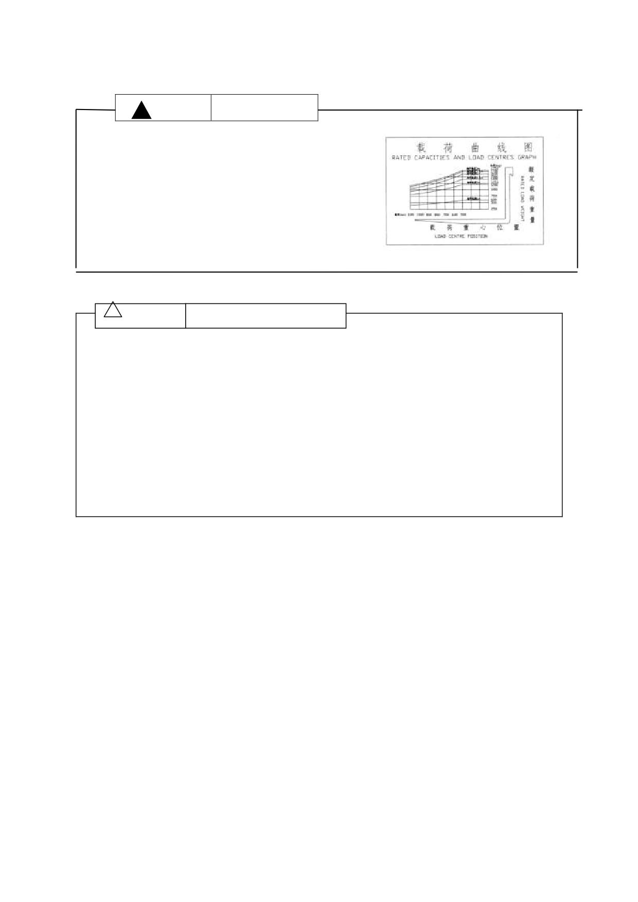
! Caution
Capacity chart
The chart given shows the relation between the
load center and the weight of loads.
Before loading, make sure that the load and the
load center distance in the range of capacity chart.
If the load‟s shape is complex, put the most
weightily part on the middle of the forks, and
close to the fork carriage.
! Caution
Velocity and acceleration
One object will keep quiescence until force works on it. Also, a moving object will
keep moving until force works on it .This is just inertia.
According to inertia, when truck starts moving, one force works backwards, and when
truck stops moving, one force works forwards. So, it‟s dangerous to brake suddenly,
because it causes one large force works forwards, and it‟s easy to cause truck overturn or
load slide off.
When the forklift makes a turn, will exert a centrifugal force outward from the curve
center. This strength pushes forklift outwards and causes it to turn over. About stability
region is very small, so decelerate when turning. If the cargo transported at the high
position, it‟s easier to turn over.
19
6.Running-in of the new truck
We recommended operating the machine under light load conditions for the first stage
of operation to get the most from it. Especially the requirements given below should be
observed while the machine is in a stage of 100 hours of operation.
1. Must prevent the new battery from over discharging when early used. Usually should
recharge when discharging down to 20%.
2. Perform specified preventive maintenance services carefully and completely.
3. Avoid sudden stop, starts or turns.
4. Oil changes and lubrication are recommended to do earlier than specified.
5. Limited load is 70~80% of the rated load.
20
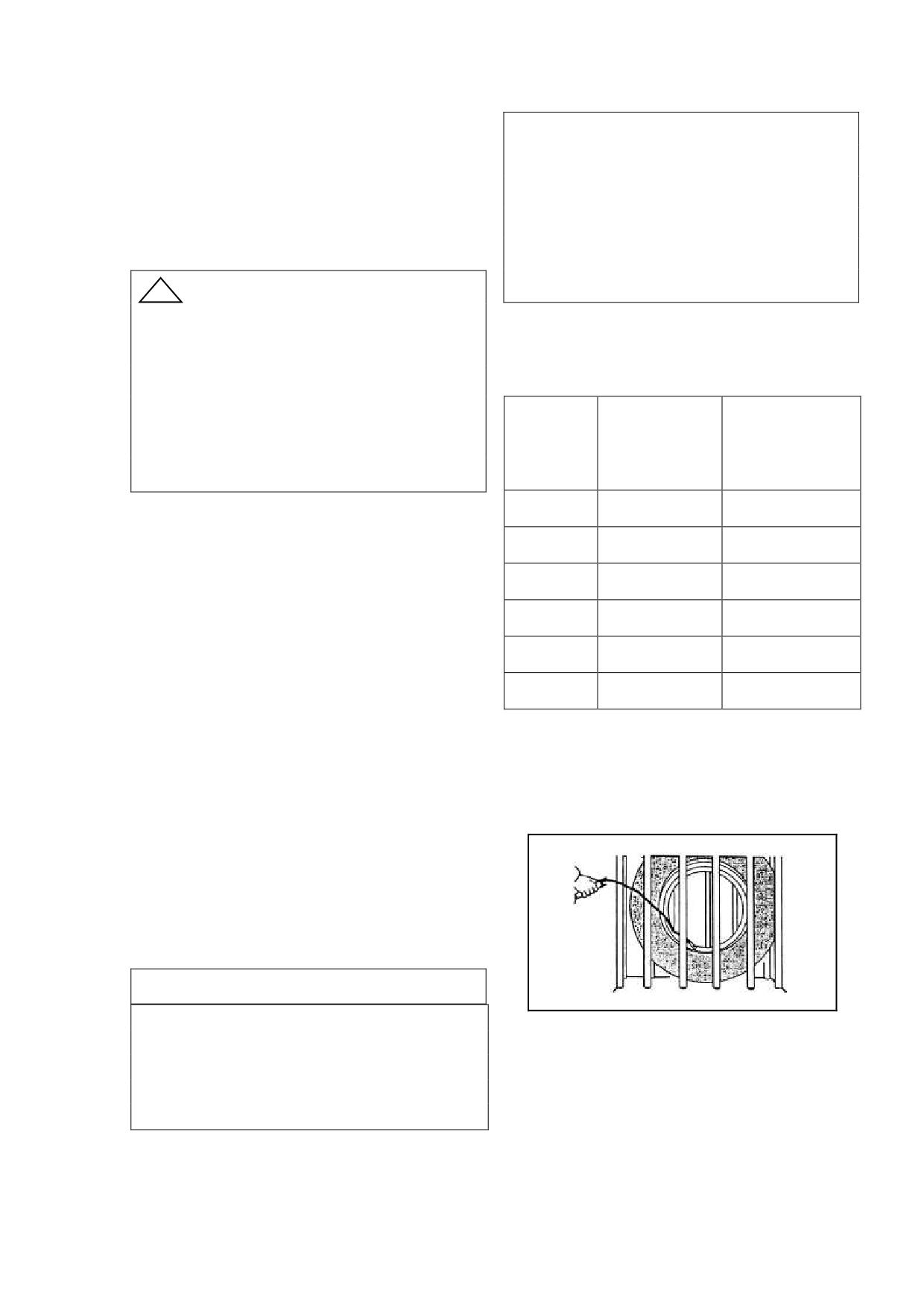
7.Daily maintenance
Warning!
The earnest complete maintenance, can
When using an air compressor, at first,
keep the forklift to be at the good status. And
adjust the air pressure of the compressor.
the safety of the truck is related with your
Otherwise it will cause a serious accident,
job and your life.
since the maximum pressure of compressor
!
Warning
higher than the pressure tire can bear.
except checking lights and operating
capability, you should shut off the key
Tire Pressure (GB/T2982-2001)
switch and pull out the plug before checking
electric system.
Driving
Turning wheel
Truck
prohibit operate forklift with trouble.
wheel
(rear wheel)
type
little trouble brings big accident.
(front wheel)
1-1.5t
860KPa
1000KPa
1. Inspect oil leakage: include hydraulic
1.8t
1000KPa
1000KPa
oil, electrolyte and brake fluid
Inspect connector of the oil pipe and
2-2.5t
850KPa
900 KPa
storage battery to see whether there is any
3.0t
850KPa
900KPa
leakage. Use your hand or eyes to inspect,
Forbid to use a flame.
3.5t
850KPa
900KPa
4-5t
930 KPa
860KPa
2. Inspect tire
Caution!
Turn the tire valve cap counter
clock-wise and move it. Using a tire pressure
Above for the pneumatic tire pressure, is not
gauge, measure the inflation pressure, and
suitable the solid tire.
adjusting it to the specified pressure, if
needed. After making sure there is no air
leakage from the tire valve, reinstall the cap.
Check that each tire does not get damaged at
the tread surface or side face. Make sure the
wheel felloe is not bended.
Warning!
Since the tires of forklift truck need have a
high inflation pressure to carry heavy loads,
even a small bending of rims or a little
damage at the tread surface could cause an
accident.
21
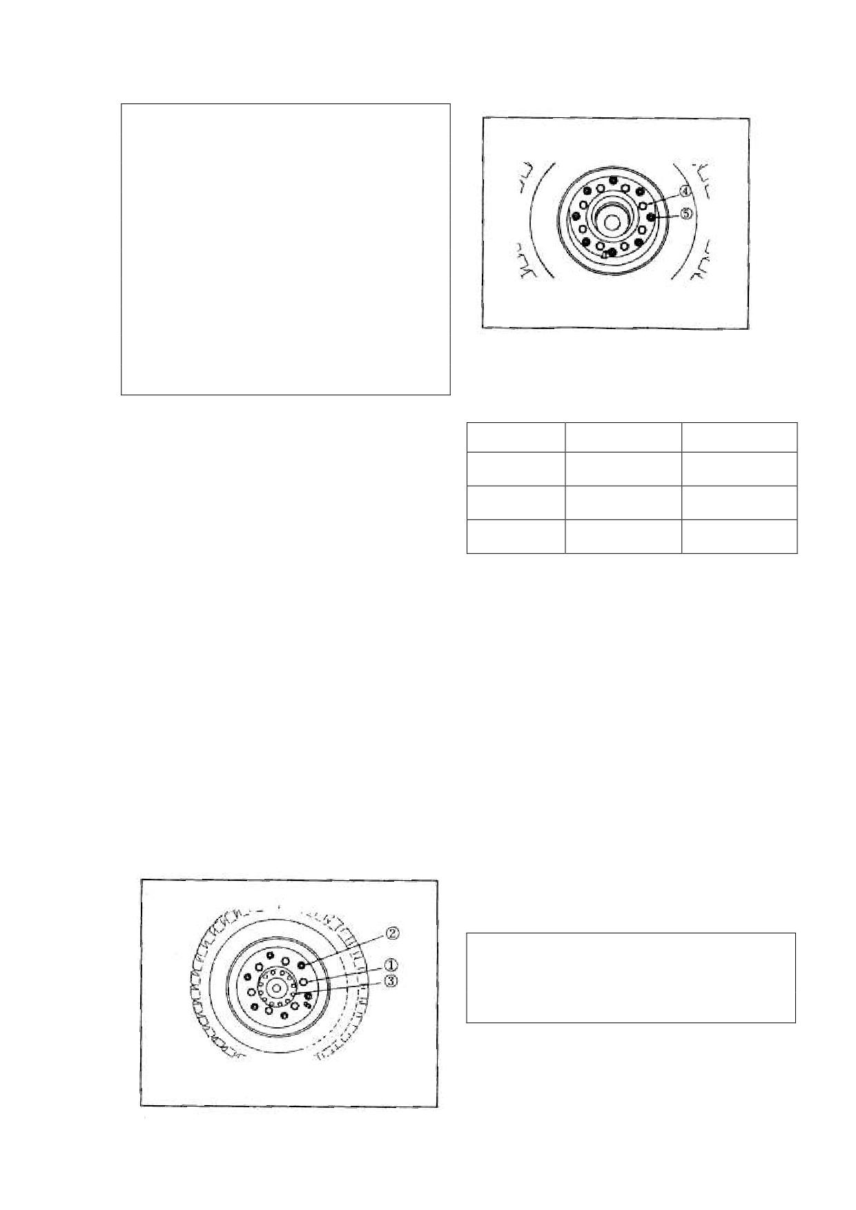
Warning!
All bolts and nuts should be screw tight
to the stipulation torque after the tire and the
wheel felloe was assembled, then charge is
allowed. Types have expansion energy after
changing, so the tire pressure does not
surpass the rating.
Please put the tire in a protection frame
or tie it with a iron chain when charging to
Tighten torque refers to <<Bolt tighten
prevent accident happening.
torque force table>>
3. Replace tire
Truck type
Front nut
Rear nut
When the tire is damaged, you should
1-1.8t
157-176 N.m
76-107 N.m
replace it in time. Use a jack to make the tire
just beyond ground, then put a wood block
2-3.5t
441-588N.m
157-176 N.m
under the chassis. Loosen nut ① or ④,
4-5t
441-588N.m
157-176 N.m
replace a new tire. Tighten the nut crossly
and symmetrically.
5. Check brake pedal
Step the brake pedal, check it for
4. Inspect the torque of hub nut
slowness or block. The proper brake distance
Check the torque of hub nut whether meet
is 2.5m when free load. Adjust the height of
the requirement.
pedal to 115~125mm. Adjust brake booster
①Hub nut
push rod clearance to 1-3mm. The brake
②Divided rim bolt (some trucks do not
lamp should be lighted when the brake pedal
have )
steps on 10-20mm.
③Driving axle bolt
④Rear hub nut
⑤Divided rim bolt
6. Check the parking brake lever
Driving wheel (front wheel, expect 1-1.5t)
The force of hand brake lever is adjusted by
the bolt on the top of lever. The force
increases clock-wise screwing, and decreases
counter lock-wise screw.
Caution
To step the brake pedal is helpful to tighten
or loose the hand brake lever.
22
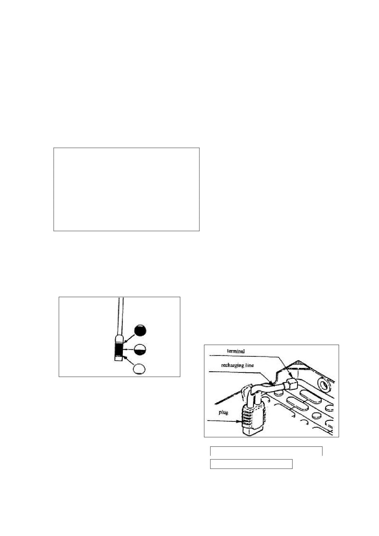
7. Check accelerate pedal
5) Loose the cap of hydraulic oil, pull
The acceleration changes as the stroke
out dipstick
changes.
6) Set a plate under the chassis, then
loose the fuel drain plug, and put the old oil;
8. Brake fluid level check
7) Dispose the old oil according to local
Open the brake lubricated cap cover. Check
environmental protection laws;
the fluid level in the range allowed. If lack,
8) Twist the fuel drain plug, join the new
please add, and check if there is air mix into
hydraulic fluid, and inspect whether have a
the pipe.
leakage;
9) Start the truck, lifting for 3-5 times,
Caution
and tilting for 3-5 times;
Please use brake fluid with one type, do not
10) Add hydraulic oil to required scale.
mix.
·Don‟t spatter the brake oil onto the surface
11. Drivers seat adjustment
of paint otherwise the paint will be damaged.
Make sure the driver‟s seat is properly
·When adding fluid, due should be taken to
located. If not properly, shift the adjusting
prevent dirt or water from entering the
lever to the right and move the driver‟s seat
reservoir.
to a position which provides easy access to
all foot and hand controls. After adjustment,
shake the driver‟s seat a little to be sure that
9. Check hydraulic oil
it is securely locked. Adjust the weight.
Loose the cap of hydraulic oil inside of right
frame, pull out dipstick and check it if the oil
12. Check battery
level is between the scales. Add oil when
Check the battery whether be installed
lack.
firmly.
Check proportion of electrolyte. Refer
to “battery” section.
Check the terminal for loose or damage.
Otherwise it will be adjust or replace.
10. Replace hydraulic oil
Replace hydraulic oil once half year on
schedule.
1) Stop the truck on smooth ground;
2) Turn steering wheel right to the
bottom, and enable the fuel drain plug to
have the enough space;
Pull in the plug and close the hood.
3) Tilt mast backwards to the bottom, and
Turn on the key switch
fall the forks to the ground
4) Pull on the hand brake
23
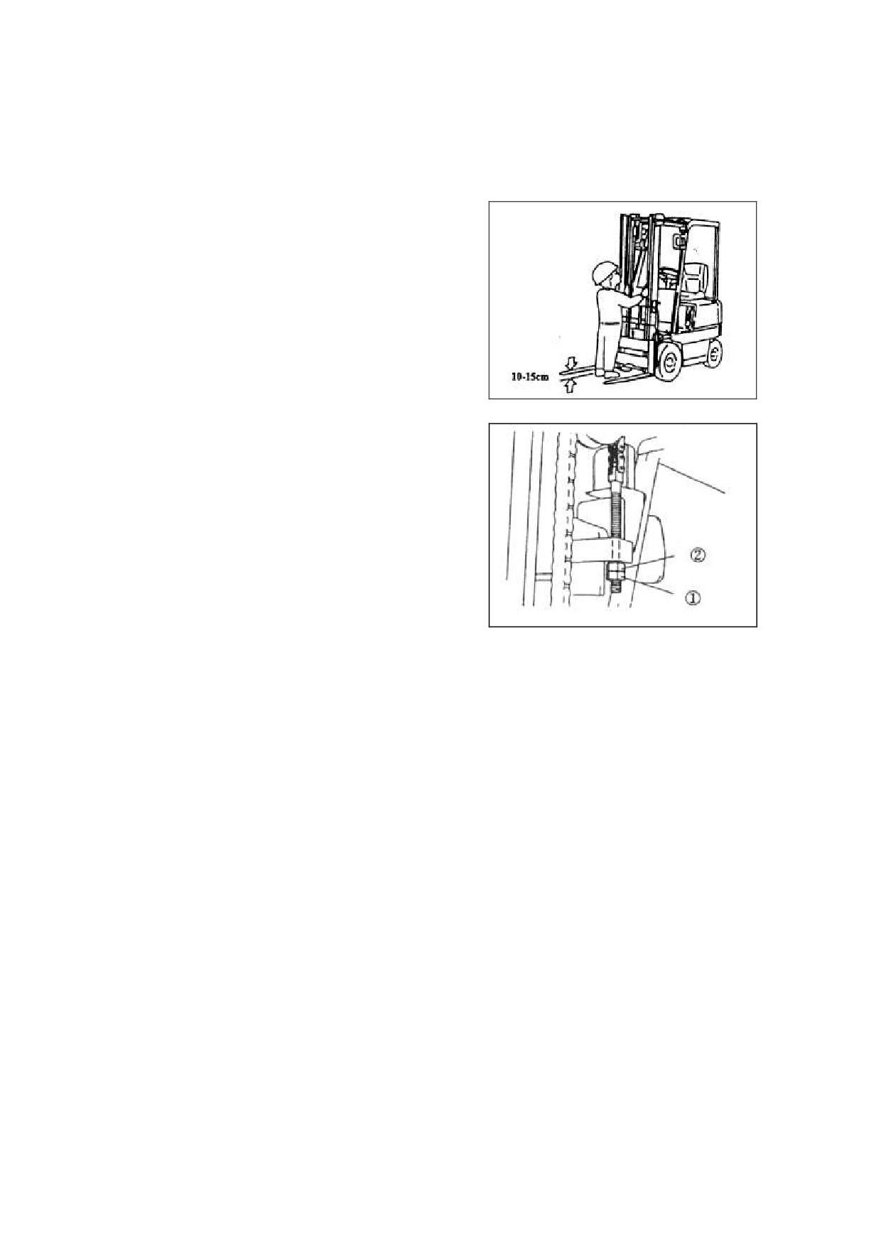
13. Instrument check (include battery
and left chains are equal.
capacity and error diagnose)
③ Adjust the chain tension: loosen the
Refer to instrument section.
lock nut (1) and adjust the chain by nut (2),
then locked nut (1).
14.
Lifting lever, tilting lever,
attachment lever
Check the lifting lever, tilting lever and
attachment lever for looseness. Return
position well.
15.Mast
Check the mast and the forks to insure
that:
1) The fork does not have crack and
distortion.
Forks were installed
firmly and correctly.
2) Check the oil cylinder, oil pipes for
leakage.
3) Check the rotation of idler wheel
4) Check the mast for crack or
distortion
5)
Lifting
lever,
tilting
lever,
attachment lever
Check the mast whether works normally,
18. Check steering system
whether have unusual sounds.
Turn the wheel right and left separately
to check steering system.
16. Mast lubrication
You should grease lubrication to the
19. Turn signal, horn and other lamp
orbit of mast on schedule base on
check
requirement.
Make sure that the turn signal operates
Adjust the lubricate schedule according
properly by pull/push turn signal switch.
to your working condition. Add times when
Make sure that the sound of horn is
busy.
properly by press the horn button
To coordinate forklift's operation,
Check the other lamp and back-up
grease lubrication to the guide pulley and in
buzzer.
outer upright mounting.
20. Battery maintenance
Refer to battery section.
17. Lift chain tension check
① Raise the fork about 10-15 cm above
21. Other
the ground vertically.
For instance, pay attention to abnormal
② Push the middle of the chain with the
noise.
thumb. Make sure the tension for the right
24
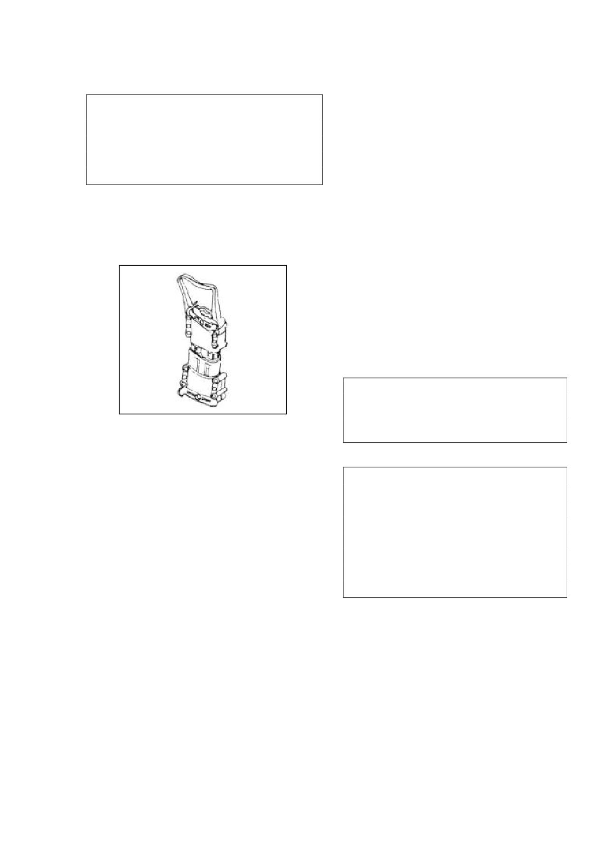
8.Driving and operation
backward.
! Warning
(6) Loosen the hand brake lever
Before operating the truck, check all controls
Step the brake pedal and push the
and warning devices for proper operation. If
any damage or fault is found, don‟t operate
hand brake lever to the front position.
truck until corrected.
Hold the steering wheel with your left
Driving
hand and attach your right hand.
(1) Open the cap, and insert the storage
Traveling
battery plug, then close the cap.
Step the accelerate pedal slowly, the
truck will travel forward or backward.
Decrease speed
Loosen the accelerate pedal slowly, the
truck will decelerate.
Warning:
Don‟t step the accelerate pedal and brake
(2) Set the direction switch to neutral
pedal at the same time.
position
(3) Turn on key switch
Caution:
Decelerate the truck in the situations
Hold the steering wheel with left
following:
hand and turn on the key switch with right
turning;
close the goods or pallet;
hand.
close the deposit area;
(4) Tilt back the mast
enter a narrow passage
the condition of road surface is bad.
Control the lifting lever to set the
Turning
bottom of the fork 150-200mm above the
Unlike general passenger-cars, the
ground. Control the tilting lever to fully
turning wheels are located at the rear of
tilt back the mast.
the truck. This cause the counterbalance
swing out when turning.
(5) Control direction lever
Slow down the truck and turn the
Forward : Push the direction lever
steering wheel toward the side which you
are turning. The steering wheel should be
forward.
turned a bit earlier than as with the front
Backward:Pull the direction lever
wheel steering car.
25
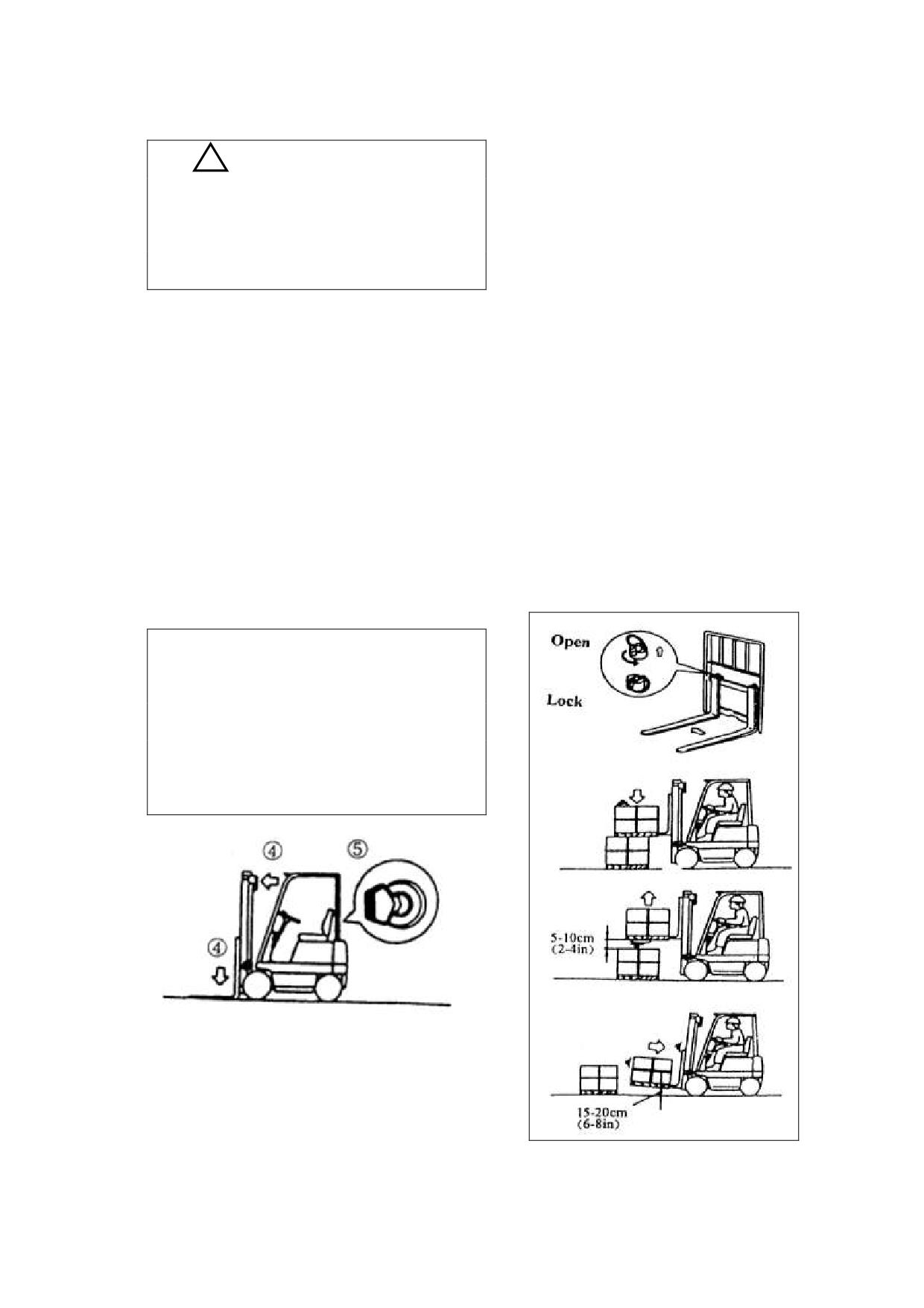
be handled.
! Caution
The pallet should be evenly positioned
Drive the truck slowly and control the
across both forks.
steering wheel carefully, assure there is
Insert forks into the pallet as far as
enough space to steer.
possible.
To raise loads from the ground:
Stopping or parking
① Firstly, lift the forks 5 to 10 cm off
①Slow down and press the brake pedal to
the ground or floor and make sure loads lay
stop the truck.
stably.
② Place the shift lever in neutral.
② Then tilt the mast backwards fully
③ Pull up the parking brake lever.
and lift forks up to 15 to 20 cm off ground
④ Down the forks on the ground, tilt
then start running.
mast forwards fully.
·When handling bulky loads which restrict
⑤ Place the key switch in “OFF” to shut
your vision, operate the truck in reverse
off the battery. Remove the key and
except when climbing grades.
keep it.
Caution
·Don‟t dismount from the moving truck,
never jump from the truck.
·Don‟t parking the truck on the working
road.
Loading
The forks should be adjusted properly to
maintain the balance of load.
Place the truck right in front of the load to
26
Caution:
Stacking load
Decelerate the truck in the situations
following:
·When approaching the deposit area slow
turning;
down your truck.
close the goods or pallet;
Stop the truck right 30 cm far away from
close the deposit area;
enter a narrow passage
the position where your load is to be
the condition of road surface is bad.
deposited.
·Check the condition of the deposit area.
Un-stacking load
Tilt the mast forward until forks become
·When approaching the area where the
to horizontal. Raise forks until they are a
load is to be retrieved, slow down your
little higher than the deposit position.
truck.
·Move forward to place the load directly
Stop the truck 30 cm far from the load.
over the desired area and stop the truck.
·Check the condition of the load.
·Make sure your load is just over the
Tilt the mast forward until forks become
desired area. Slowly lower the load into
horizontal. Elevate forks up to the position
position. Make sure the load is securely
of the pallet.
stacked.
·Make sure forks are positioned properly
·Do necessary lift-tilt operations and then
to the pallet. Move forward slowly to
back away to make the forks leave loads.
insert forks into the pallet as far as
·After making sure the forks leave the load,
possible.
lower the forks to the basic position (15 to
Caution
20 cm off the ground).
If the forks are hard to be fully inserted,
Tilt the mast backwards.
use the following procedure: Move
! Warning!
forward and insert 3/4 of the forks. Raise
·Never tilt the mast with loads upraised
the forks 5 to 10 cm and move backward
2m or more.
10 to 20 cm with the pallet
on the
·Don‟t leave or dismount from the truck
forks, and then fall the pallet to the stack.
when the load is raised high.
Move forward again to insert the forks
fully.
·Raise the forks 5 to 10 cm off the stack
27
·Check all around the truck to insure that
the path of travel is unobstructed and back
away slowly.
Lower forks to a height of 15 to 20 cm
above the ground. Tilt the mast backward
fully and move to the desired area.
Check after operation
Clean and check the truck after operation:
·Damage or leakage.
·Add grease if necessarily.
·Check the tire if it is damaged or inset
with foreign body.
·Check the wheel hub nut if it is loose.
·Check the height of electrolyte surface.
·If you haven‟t lift the fork to the max.
height in the day, you should lift it to the
max. height 2~3 times.
! Caution
·If you find any trouble, must repair it in
time.
Prohibit operate the forklift before
repairing it completely
28
9.Deposit
! Warning
Daily Depositing
a. The stow-wood must be single and
hard enough to support the truck.
①Park your truck at the area appointed,
and block the wheels to prevent
b. Don‟t use a stow-wood higher than
accidental roll.
300mm(11.81 inch).
②Make sure the shift lever on neutral
c. Lift the truck to the height of
position.
placing on the stow-wood.
③Pull up the hand brake lever.
d. Place two same size stow-woods
④Shut off key switch and operate the lift
and tilt lever several times so that the
under the left and right sides of the truck.
inner pressure in the hydraulic tube will
e. After supporting the truck with
decrease.
stow-wood, swings the truck forward,
⑤Cramp out the electrical outlet.
backward, left and right, check its safety.
⑥Take out the key and deposit it in a safe
① Operate the forklift once a week,
position.
and be required to lift the forks to its max.
Deposit the truck for a long time
height many times .
On the basic of the “daily depositing”
② Check the proportion and the level
you should do these checks and
of electrolyte once a month
③ Charge the battery equally once a
maintenance additional:
month.
①Take out plug to prevent discharge and
place in shade.
②Brush antirust oil on those parts which
Working after long deposit
is exposed such as piston rod and axle
① Get rid of antirust oil.
easy-rusted.
③Cover breather hole and so on which
② Discharge the gear oil from driving
humidity easy to enter.
axle, decelerator box, and clean up the
④Cover the whole truck with mantle
internal of them. Add new oil.
⑤All lubrication points add the oil
③ Charge the battery then install it to
(grease).
truck, and do not forget to connect the
⑥Fill up the truck body and counter
down-lead.
weight with stow-wood to reduce
④ Check carefully before starting,
bearing of the two rear wheels.
include start, advance, and back off,
turning, lift, fall, tilt and so on.
29
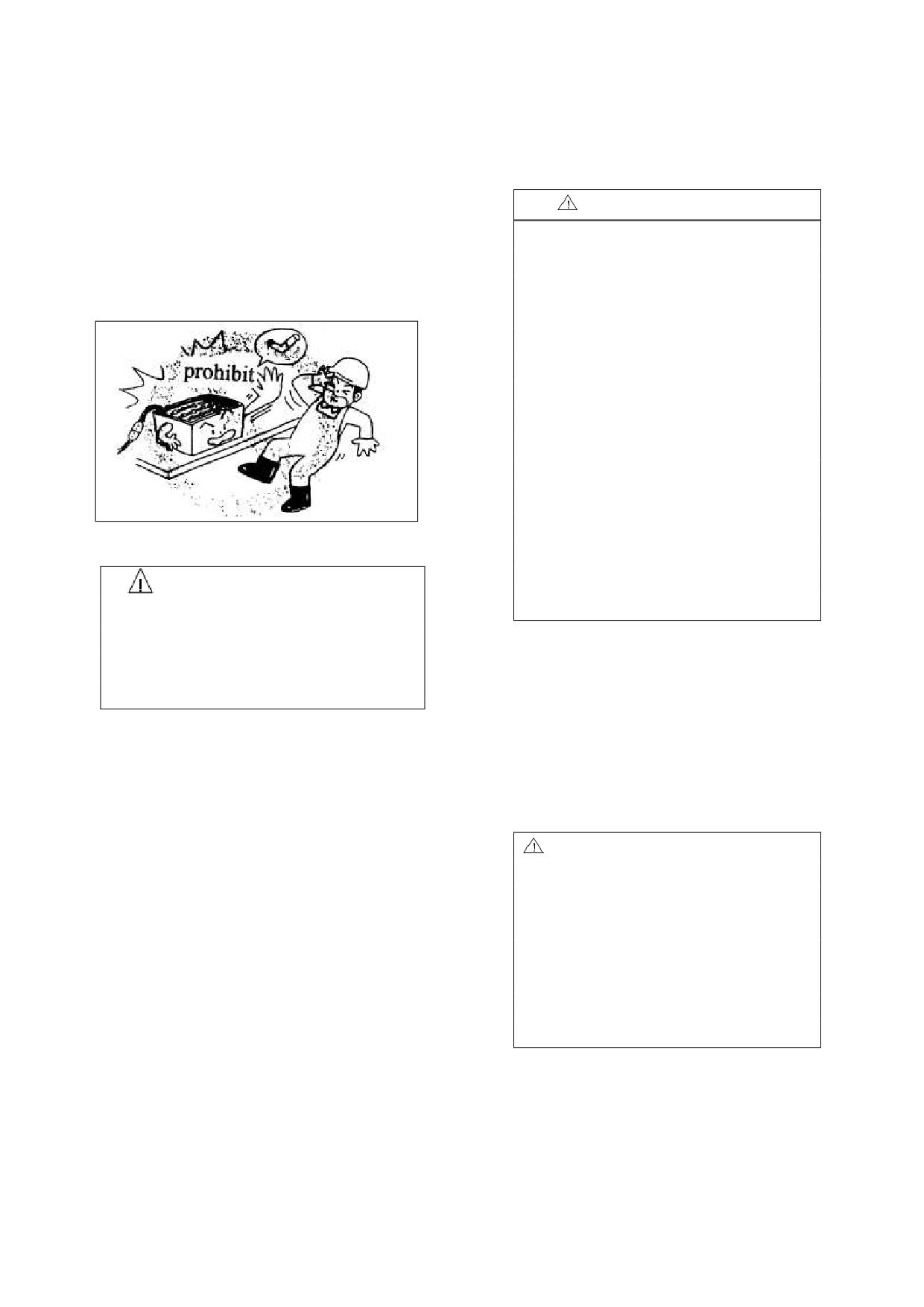
·When electrolyte level is low,you must
10.Storage battery
add distilled water to the level appointed.
Attention for using battery:
1. No firing
Warning
Explosive gas can be produced in the
1. The shortage of the electrolyte will
internal of battery,smoking,flame and
cause the storage battery overheated,
sparkle ,each can easily cause battery
even cause the system part of storage
explosion.
battery and electric combustion.
2. Vitriol include in the electrolyte can
create burns, see doctor for emergency
treatment quickly if touch it un-carefully.
Splashing to the skin or eyes:wash with
water 15~20 minutes;
Splashing to the clothes : take it off
immediately
·Careless drinking:Instead of plenty of
2. Protection against electric shock
water and milk.
3 Wearing glasses、rubber overshoes and
Warning
rubber glove.
·Battery has high voltage and energy.
·Do not bring short circuit.
Remaining clean battery
·Do not approach tools to the two poles of
Keep dryness and cleanness on the
the battery,which can cause the sparkle.
surface of battery .the poles for
connection are also dry and clean.
3. Correct wire connection
Operator must screw down the vent-cover
Not allowing instead anode of
of battery.
cathode,otherwise,resulting in sparkle or
burning or explosion.
Warning
1. Do not use dry cloth or fiber cloth to
4. Do not over-discharge
clean the battery,avoiding static to cause
If you use the energy of battery till the
the explosion.
forklift can‟t move, you will shorten its
2. Pull out battery plug.
working hours.
3. Cleaning with wet cloth.
·When the display of battery shows low
4. Wearing glasses、rubber overshoes and
capacity, please charge it quickly.
rubber glove.
5. Inspection for electrolyte
Forbidden to use the truck when the
electrolyte is shortage.
Inspection for electrolyte level every
week.
30
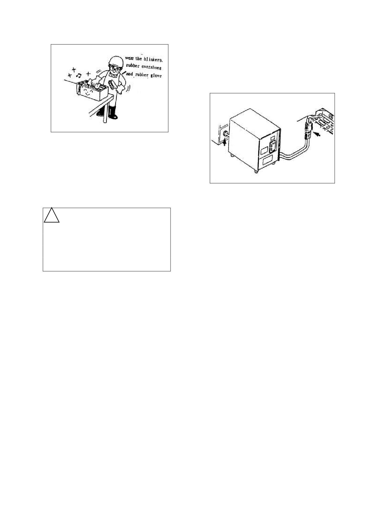
· Check connections whether there is
loosen, fasten if any.
· When wire or electrical outlet was
damaged,please do not charge.
Measure in summer
In summer,water in the electrolyte is
easy to evaporate,therefore,electrolyte
must often be inspected if electrolyte is
low,you must add distilled water to the
level appointed.
4. Open forklift cover and battery lid when
charging,in order to release the explosive
! Warning
gas .
5. In the progress of charging,electrical
Filling with distilled water beyond the
source switch and battery pin are not to
regulated range, Spilt electrolyte will
pull out,otherwise will destroy pin and
electrical units. The normal procedure is
cause corrosion and electricity leakage.
that:
Measure in winter
press down the stopping button firstly,
·Keep effective and good surrounding for
and then pick out the pin.
charging.
·To prevent discharging,when it is
Charger
cold ,pull out the battery pin.
1. The battery group is equipped with
JCD-35A-24 type automatic high frequency
·Take measures,such as,covering battery
computer to charge. The input power supply
for warmth.
is AC single-phase with 220V, input current
·Charge in time after work.
is not lower than 15A. The output voltage is
DC36V and its max. charge current is 35A.
The charging process is automatic, the detail
Attentions for charging
of using method please refer to the charger
operate manual.
1. Please charge in the well-ventilated and
2. Connect with earth wire when the charge
appointed site.
is used.
2. Mark „no smoking‟ when charging.
3. To replace fuse,make sure that the input
3. Inspect wire and electrical outlet.
and output circuits are disconnected.
4. Only professional person is allowed to
·Before charging,please examine wire
disassemble the cover to check and repair.
and electrical outlet whether been
5. Do not rebuild or disassemble charger.
damaged.
6. In high temperature season, pay attention
31

to prevent the charge from destroy caused
Specification for distilled water:
by high temperature. Stop the charge in
Ingredient
Index
short time when it is necessary.
Appearance
No color crystal
7. If a non-automatic charger is used, the
Dry residue
%
≤0.005
charge voltage, current and charge time
Resistively(250C)Ω·cm
≥7×10⁴
should be adjusted, and check the rate of
battery electrolyte timely, so as to make sure
Fe
%
≤0.0004
that the charge of battery group is in good
Cl
%
≤0.0005
condition. The adjust parameters please
Mn
%
≤0.00002
refer to “battery charging” in the follow.
Organic
compound
8. Do not continuously charge.
≤0.0002
(calculating oxygen)
%
·Continuously charge several batteries will
Magnesium
oxide
+
cause charger overheat even be damaged.
You can use the charger again after it has
calcium
≤0.005
been rested for an hour.
oxide
9. Select the charger according to battery‟s
%
voltage and capacity (refer to parameter
Ammonium
table)
≤0.0008
%
Nitrate or nitrite
%
≤0.0005
Battery charging
1. There are two charge mode can be
Confect course
adopted, including intelligent charging
① Wear the blinkers, rubber overshoes
and constant current charging. For the
and rubber glove.
first charging, adopt the constant current
② Please pay attention to add the acid
charging.
to water slowly, churning up at the
·All the batteries of the new truck are not
added electrolyte.
same time, make it mix equality.
Electrolyte confect
!CAUTION
Type
D-500
Don‟t pour the water to the acid, in
Parameter
D-420
D-630B
order to avoid the temperature of liquid
Name
D-700
surface turning high suddenly to cause
Specific gravity
boiling and splashing out to hurt
1.265g/cm3
1.275g/cm3
of acid
someone.
Volume
③ When the electrolyte is cooled to
Water
3.1:1
2.6:1
ratio
30℃, pour it into battery. It is proper
and
Quality
to pour the electrolyte
15-20mm
vitriol
1.7:1
1.65:1
Ratio
above the protection piece (without a
Vitriol Ratio
1.835g/cm3
dobber) or 1mm distance between
dobber and cover (with a dobber).
Suitable
for
④ Only when the temperature of the
Vitriol standard
GB4554-84 or special
electrolyte is below
35 ℃ (after
for battery
about
3-5 hours), can be first
charged.
32

4.5-5 times than rated capacity.
Caution
Charging current(A)
Charging
The time that is from pouring the
Truck
Battery
voltage
1st
2nd
electrolyte into the battery to starting
type
type
(V)
phase
phase
first charging can‟t be exceeded
12
hours.
1-1.8t
D-420
72
40
20
⑤ The specific charging cable should
2-2.5t
D-630B
72
63
32
be connected to charging machine.
3t,3.5t
D-500
120
50
25
Caution
Be sure to notice that the polarity
4-5t
D-700
120
70
35
sign on the plug must keep comfortably
to the out specific charging end node.
Charging time(h)
35-45
35-45
When the charging cable is
connected to the storage batteries, please
c. Adjusting the specific density and
pay attention to keeping comfortably on
height for the electrolyte
the polarity sign. Otherwise maybe you
If the specific gravity is smaller, it will
will damage your battery.
be adjusted as follow: then take out
some electrode from the battery, pour
the compounded sulfuric acid that its
⑥ Inspect
specific gravity is 1.400g/cm3.
The voltage value that the power
needed is the number of the serial
If the specific gravity is larger, it will be
battery three times.
adjusted as follow: then take out some
Battery voltage
electrode from the battery, pour some
Truck type
Battery
(V)
distilled water, but you must keep the
1-1.8t
D-420
48
electrode height accord with demand
d. After adjusting, you should keep
2-2.5t
D-630B
48
charging on 1 hour; make the density
3t,3.5t
D-500
80
of electrode even upper and under. At
this time we have finished the first
4-5t
D-700
80
charging.
Inspect the charging machine.
e. Close the pouring plug and clean the
·Inspect every battery‟s polarity.
battery surface acid, then you can use
it.
⑦ Charging ways
(time, current as the
Caution
form)
During the charging, the temperature
a. 1st phase:most of the single battery‟s
of electrolyte should not be exceeded
terminal voltage steps up to 2.4 V;
45℃。 Otherwise you should low the
b. 2nd phase:the electrode give off a
temperature. If the temperature do not
large number of bubbles, the voltage
lowing, you should stop recharging,
and the specific gravity steadies
4
till the temperature drop down.
hours and the charging value gets to
33

occur disequilibrium among the voltage,
Daily charging
the density and the capacity.
The battery that has been made the
·Compared to most of the batteries ,
first charging and used regular, then
often finds that single battery‟s
charged again, is named daily charging.
proportion of voltage and electrolyte
Its way is almost same as the first
rises slowly during the course of charge
charging.
and during the course of discharge, its
The recharging value is 1.2 times
battery‟s proportion of voltage and
than the last electric discharging. But the
electrolyte declines faster than most of
electric-change for new battery‟s fore
other batteries.
five times should be 1.5 times than the
·Make equilibrium charge in the
last electric discharging.
following case:
·During any charge, the temperature
a. discharge voltage often drop down
of electrode should not be exceeded
ending voltage;
450C, otherwise it should be taken
b. discharge current is often larger;
measures such as reducing artificially
c. Not charge in time after discharge
charging current or lowing the
d. The electrolyte is mixed with
temperature. If the temperature doesn‟t
impurity with a little harm.
drop, you should stop charging, till the
e. It often be charged deficient or has
temperature dropping down.
not been used for a long time;
f. After taking out the battery group
Charging current(A)
Charging
Truck
Battery
for checking or cleaning settling.
1st
2nd
voltage
type
type
(V)
phase
phase
The method of Equilibrium Charge:
① Firstly, charge the battery normally,
1-1.8t
D-420
72
55
25
and then rest for 1 hour after the
end of charge.
2-2.5t
D-630B
72
88
44
② Charge it again with the current
3t,3.5t
D-500
120
70
35
belongs to the second normally
charge until the electrolyte gives
4-5t
D-700
120
96
47
off a large number of bubbles, then
stop charging for 1 hour.
Charging time(h)
4-6
6-10
③ Repeat it several times as
Adopt intelligent charging for the
mentioned above until the voltage and
daily charging. The first five charging
the density keep invariable and the
should using Equilibrium Charge
battery gives off a large number of
according to the intelligent charger
bubbles immediately when charge
operate manual.
again.
Equilibrium Charge
Complementarity Charge
·If one day‟s work cannot be fulfilled
·During using of the battery, it often
34
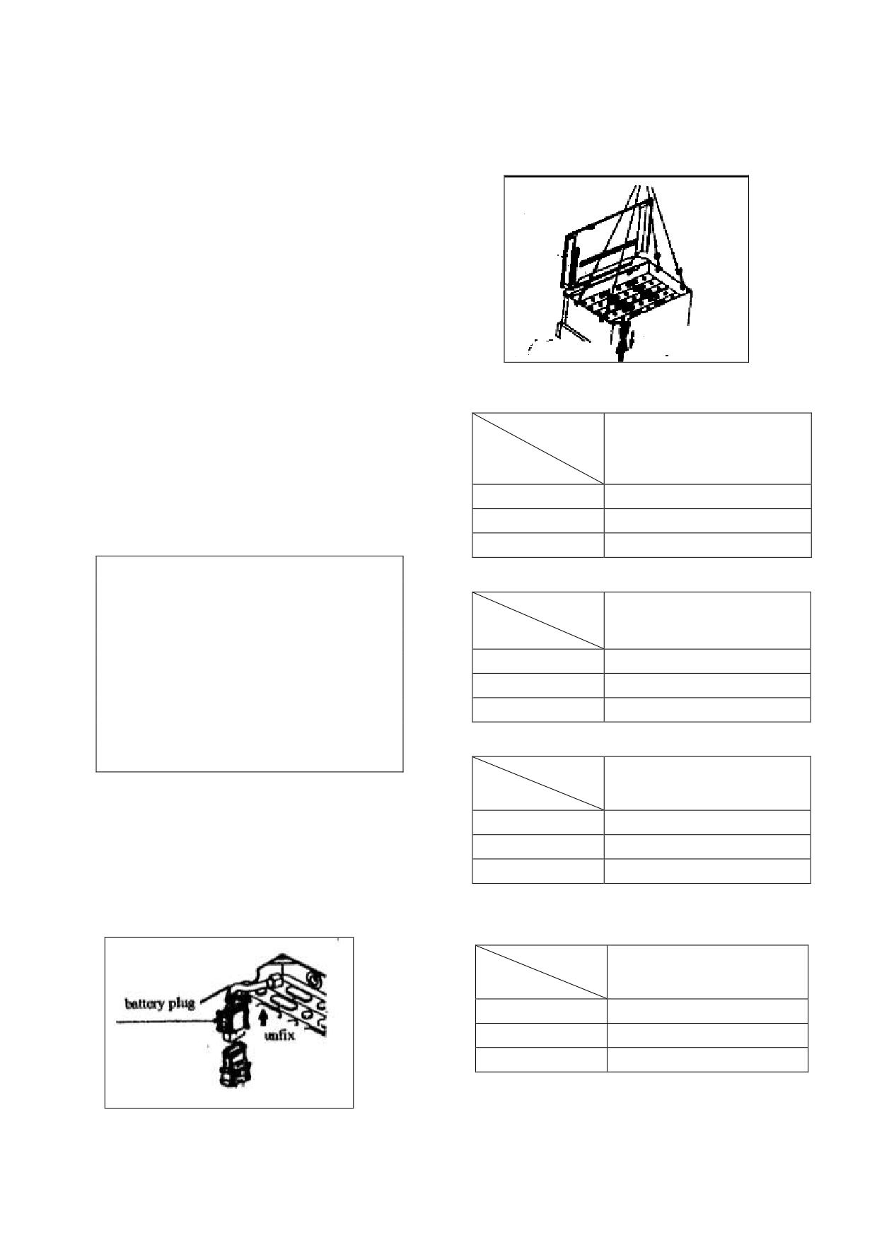
with one charge, carry out opportunity
5. Use the proper tools to pull up the
charge during breaks.
·When the temperature of circumstance
battery
is low, carry out opportunity charge.
Charge for long-term storage
·Carry out equilibrium charge before
storing.
·Carry out equilibrium charge once
every 15 to 30 days during the storage
period.
The weight and dimension of Battery
· The special orders storage battery
Model
carries on the charge according to
1-1.8t
"Accumulator Instruction for use".
Weight (kg)
Min.
700
Max.
900
Battery replacement
Dimension(mm)
465×980×780
Caution
Be sure that the voltage, the
Model
capability, the size and the weight of
2-2.5 t
Weight (kg)
the new battery are according with the
forklift truck before replacing the
Min.
800
battery.
Max.
1000
Forbid to use battery with
Dimension(mm)
570×1028×780
different voltage or capacity or weight
except being promised by factory.
Model
3 -3.5t
Weight (kg)
Min.
1200
Replacement step
Max.
1500
1. Stop the forklift truck on the plain
Dimension(mm)
710×1028×780
ground, pull up the hand brake lever.
2. Open the hood cover.
3. Disconnect the battery plug.
Model
4-5 t
Weight (kg)
Min.
1900
Max.
2200
Dimension(mm)
800×1128×780
4. Remove the lock pin.
35
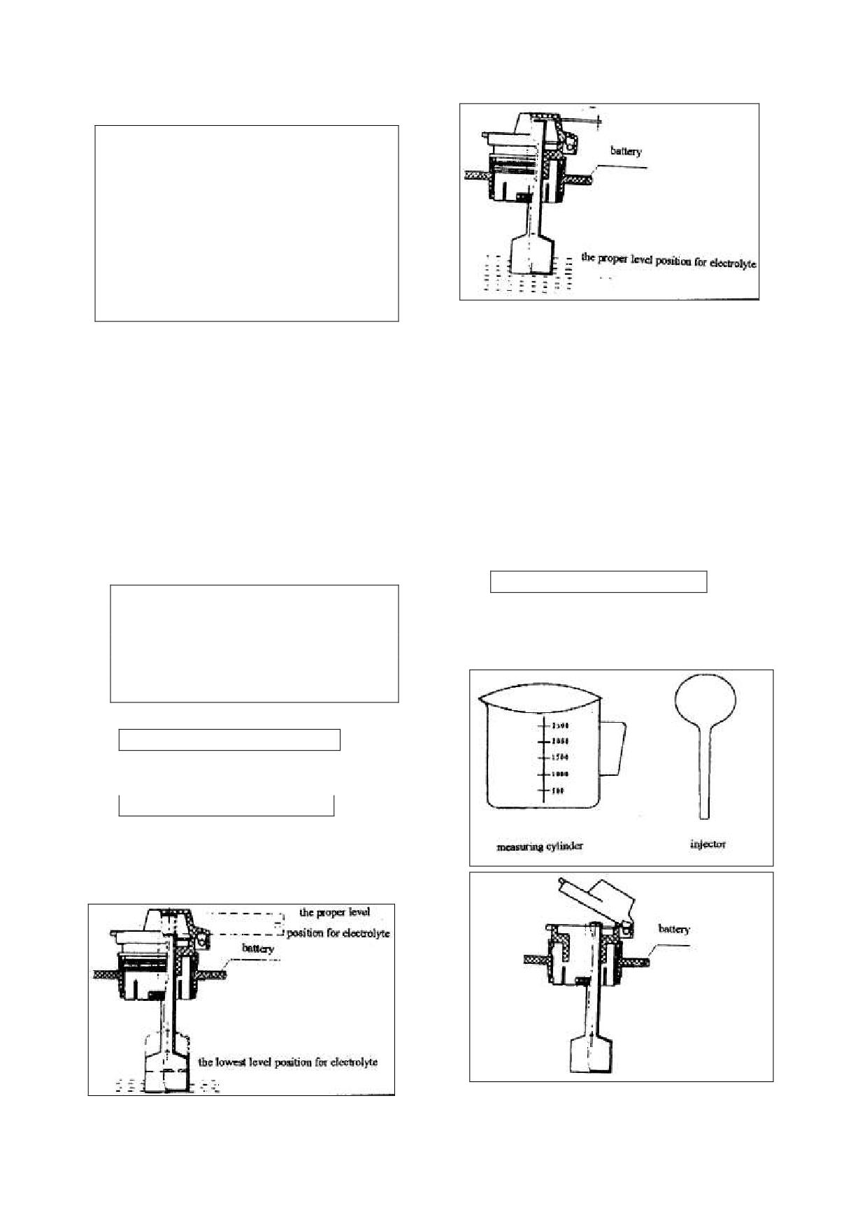
Caution
The box must be pulled up with
using 4 holes of the pothook at the same
time. It is not allowed to pull up with
only two holes. Otherwise, the
asymmetric power will cause the battery
damaged.
The steering wheel and other
equipment should not be bumped, avoid
being damaged when pulling up the
battery box.
2. Replenish the distilled water
6. After exchange the full electricity of
·Wear the blinkers, rubber overshoes
battery, plug into the lock pin, shut to
and rubber glove.
the hood cover, and plug into the pin of
① Using the measuring cylinder to
the battery hard.
take out the distilled water with a
The waste electrolyte of the
certain quantity.
replaced battery should be dealt
② Open the battery cover for every
according to environment and protection
law rather than reject at will.
battery cell.
③ Imbibe distilled water with injector
The proportion and level of electrolyte
and then supply it into the battery.
The battery with a dobber
Caution
When the red dobber rises, the
If the level of the electrolyte is low,
white line is appeared, please stop to
using the battery will cause the
replenish the distilled water.
battery over-heat and shorten the
battery‟s life.
1. Inspect electrolyte
The battery without a dobber
It is proper to pour the electrolyte
15-20mm above the electrode plate.
The battery with a dobber
Depending on the dobber of the
winded cover, and read the level
position of the electrolyte.
36
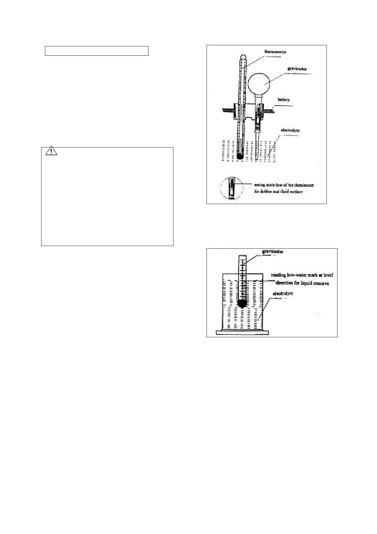
The battery without a dobber
When the electrolyte is above
15-20mm of the electrode plate, stop
replenishing the distilled water.
④ After replenishing the distilled water,
close the pouring plug and battery
cover.
⑤ Using the damp cloth to clean the
surface of every battery cell.
CAUTION
It is not permitted to overrun the
appointed tiptop level when replenishing
the distilled water. Adding it too much
will result in leakage of electrolyte, and
it will damage the truck when charging
2)Specific gravity measure
and discharging.
Using the densimeter to measure the
Draw it out with injector if adding
specific gravity.
it too much.
3. Read the specific gravity
1 ) The specific gravity of the
electrolyte should change follow the
temperature.
① Use thermometer to measure the
temperature of electrolyte.
② Put the straw of densimeter into
electrolyte uprightly, extrude rubber tube
with hand and the electrolyte will be
3)Conversion of the specific gravity
sucked into the glasses tube and then the
The specific gravity at the
floater of the densimeter will float.
standard temperature of 300C should be
③ Numerate the reading of the
densimeter.
converted as follow:
Notice:The dobber of densimeter must
D30= Dt + 0.0007(t - 30)
rise uprightly without depending on the
Where :D30 --the specific gravity at
glass pipe.
the standard temperature of 300C
Dt --the specific gravity at
the temperature of t0C.
t -- the temperature of the
distilled water during convert.
· The specific gravity that was refered
in this book is measured all at the
temperature of 30℃.
37
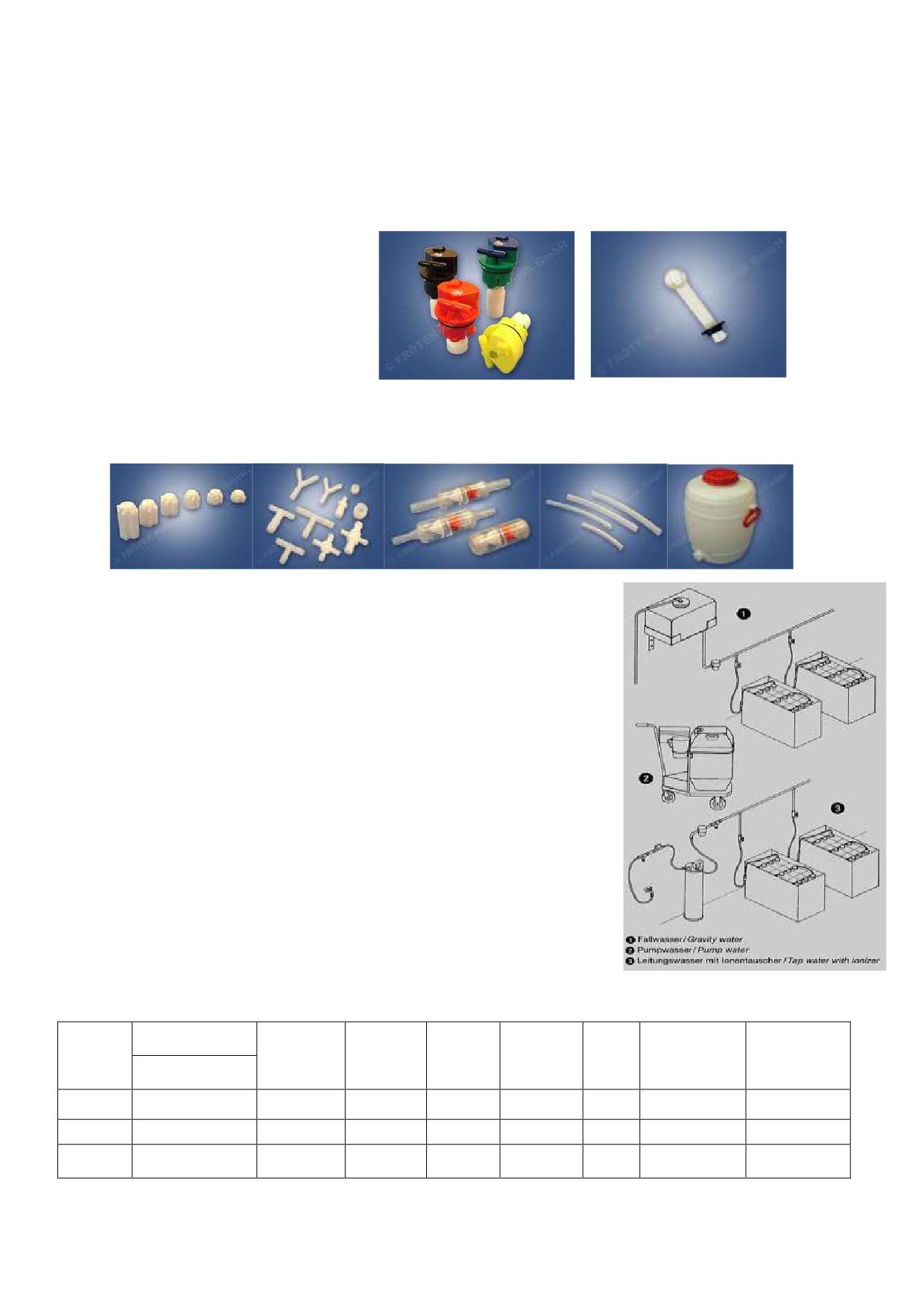
The Automatic Watering System of the Forklift Battery
1. Automatic Watering System
Makeup of the Automatic Watering
System:
Automatic Watering Plug
End Plug
Floater
T-piece & L-piece
Flow Indicator(with filter)
6mm, 8mm ,10mm watering pipe
Male & Female couplings (Kv10 and KV6, etc.)
Water Tank
2. Application Specification & Installation
During the period of development and long-term practical
usage, the leak tightness of automatic watering system has received
complete recognition.
But when you use it, you need to keep the automatic watering
system clean and there can‟t be any filth on the surface.
How to properly install the automatic watering system:
Our automatic watering system is easy to operate, no need to finish
watering the electrolyte in the storage battery by hand,
time saving and labor saving, besides, it can extend the service life.
How to correctly install the water tank, choose proper floaters,
how to confirm the specification & quantity of the installed
accessories according to different types of battery, including correct
application rules for automatic watering plug, watering pipe, T/L-
pieces and male/female couplings as well as the cleaning of the flow
indicator. We will give you a brief introduction for the above items
as follows:
Meanwhile we will offer detailed installation drawings to ensure that the clients can
correctly install and standardize the operation.
battery
Watering head
T-piece
Flow
6mm
10mm
end
Male/female
Water tank
spec.
(6-10-6)
indicator
Waterin
Watering
plug
K10
specification
T-piece
(filter)
g pipe
pipe
24V
12 pcs
1 pcs
1 pcs
3m
5m
2pcs
1pcs
30L 1pcs
48V
24 pcs
1 pcs
1 pcs
5m
5m
2pcs
1pcs
30L 1pcs
80V
40 pcs
1 pcs
1 pcs
10m
5m
2pcs
1pcs
60L 1pcs
38
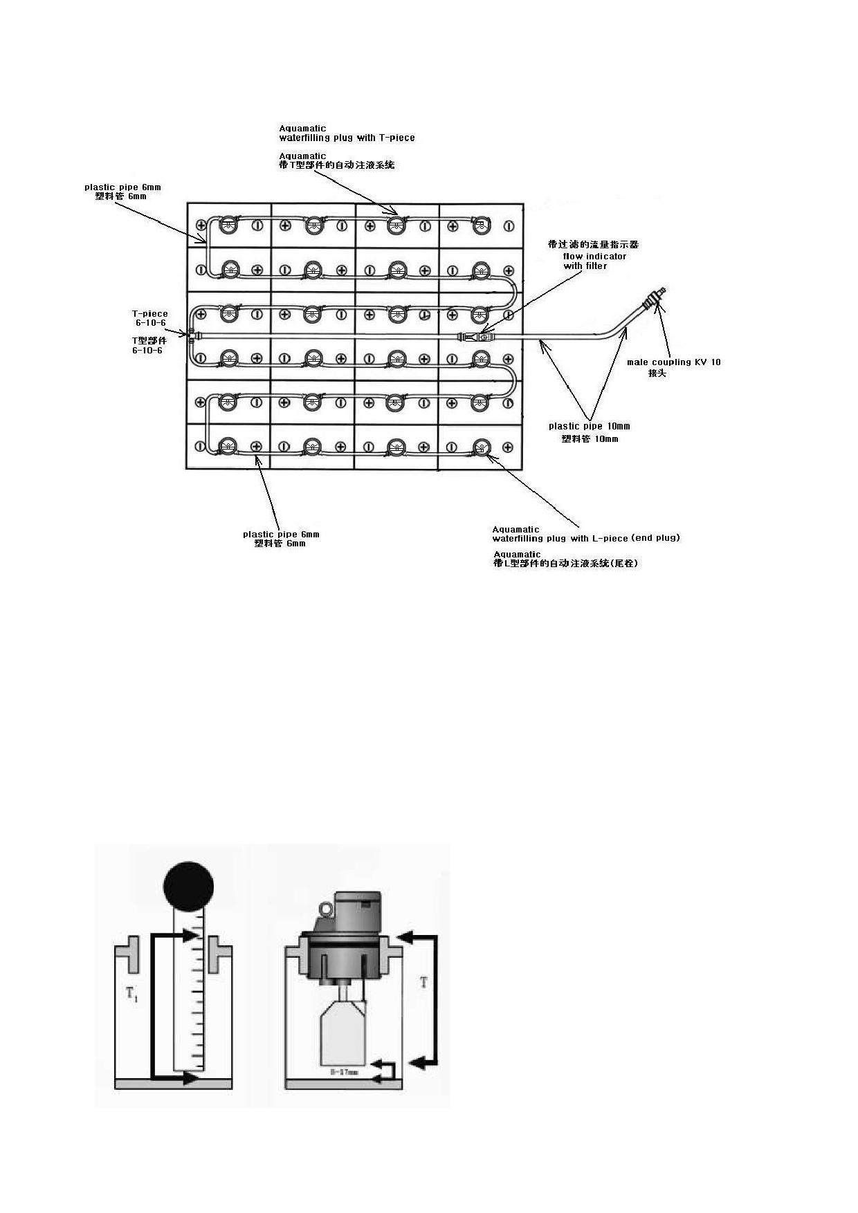
Automatic Watering System of Forklift Storage Battery-48V battery group
Floater
How to choose proper floaters correctly:
According to different storage battery, we have five kinds of floaters for you to choose. In
order to achieve our expected standard and completely reflect the effectiveness of the
automatic watering system, the most important thing is to choose proper floaters.
At present our company can offer a rule for the client to make judgment and choose the type
of floater. (see diagram)
The diagram the installation way of the floaters:
T =T1-(5~17mm)
39
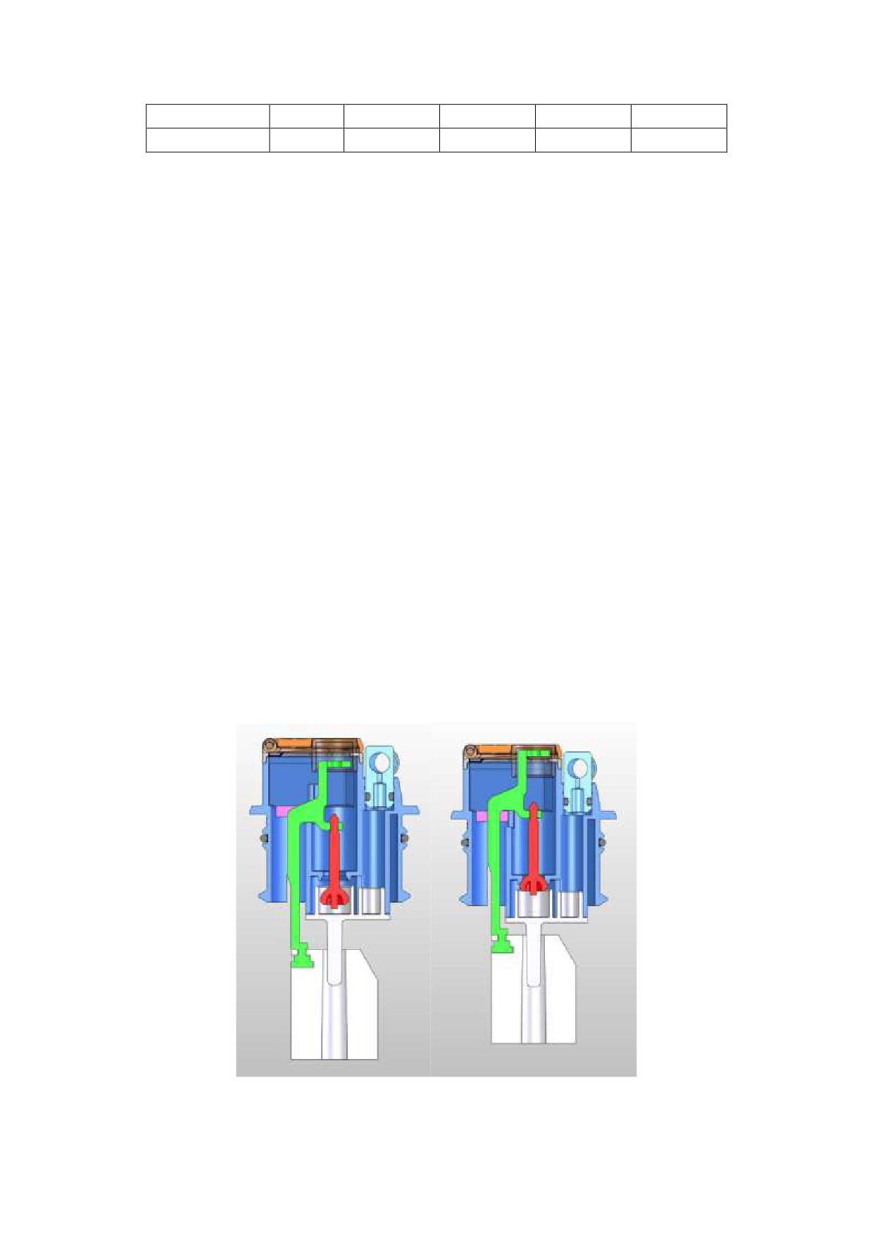
T approaching
47
50.5
58
61
72
Float
13
16.5
24
27
38
Watering Pipe
Our company offers watering pipes of different types and the clients can choose what
they need according to the specification of the battery.
The watering pipe must be perfectly sealed with T-piece and L-piece.
Notes during the filling process:
1.In order to ensure a safe watering process, we hereby recommend you to use flow
indicator (with filter), the flow indicator with filter can not only timely indicate whether it
finishes watering, but also avoid unclean impurities entering the battery to result interruption.
2.The watering pressure should be within the range of 0.2-0.6, no less than 200mbar。
3.You‟d better conduct watering within the specified periods, because frequent filling
will lead to overflowing for too much water, which will do great damage to the storage
battery.
Note:Filling after finishing charging is the best ideal state, besides, do not filling before
charging.
Cleaning
During the period of development and long-term practical application, the leak tightness
of automatic watering system has been completely approved.
When you use it, you must pay much attention to keep the automatic watering system
clean. No filth remaining on the surface.
The users should regularly clean the watering plug for the plug is a kind of plastic good.
Clean the surface directly with tap water and no need to use other detergent.
Structure Diagram of the Watering Plug:
open
close
40
Characteristics of the Automatic Watering System
No need to water by hand, labor saving.
No malfunction factor leading to damage the battery.
Easy & safe operation.
Ensure a precise electrolyte level in every battery cell.
Prevent leakage when watering.
Effectively avoid the acid liquid to erode the storage battery and the electrolytic bath.
Extend the service life of the battery.
Environment protection.
Save energy.
Function Introduction:
Function of the automatic watering system: the floater of the automatic watering plug can
reach correct water level, when the level rises in the cell, the pressure closes the valves and
prevents further water entering the cell. When the system finishes watering, the flow indicator
will stop running and you can see the water-level indicator clearly through the top of the
watering system.
Besides, the material of floater can avoid damage and ineffectiveness.
As for the structure of automatic watering system, there is a terraced step, when the
electrolyte gas rises to the watering plug, the terraced part can prevent the leakage of the
electrolyte gas as well as quickly cool the electrolyte gas to make them go back to the storage
battery in time.
41
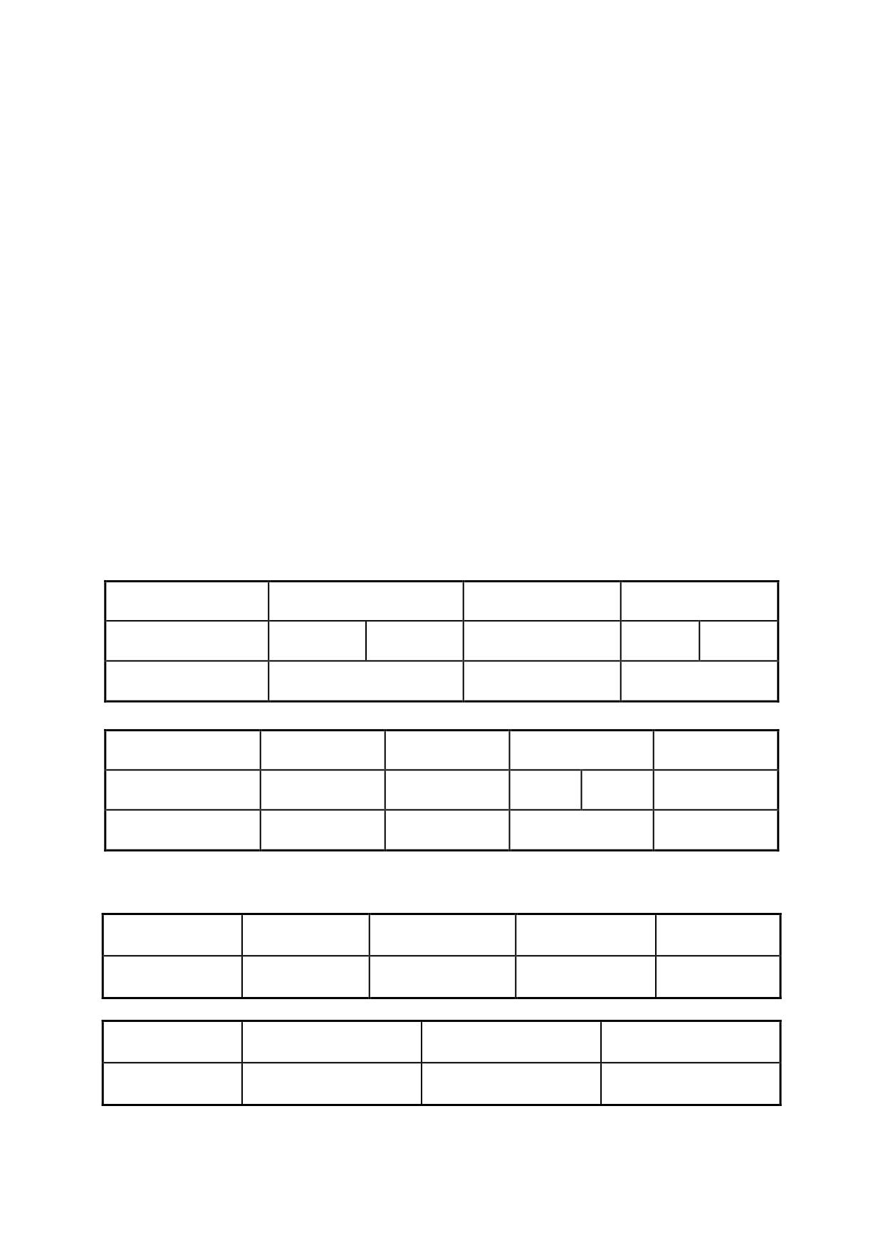
11.Maintenance summarization
·The fork lift truck needs inspection and maintenance periodically so as to make it in
good working condition.
· Inspection and maintenance are usually ignored; you‟d better find the problems and
solve it in time.
· Use the orthodoxy spare part of ZHEJIANG HANGCHA ENGINEERING
MACHINERY CO., LTD.
· Don‟t use different oil when changing or adding oil.
· Forbid to repair the fork lift truck if you haven‟t been trained.
· Don‟t rave about oil and electrolyte used at will, and carry on handling according to the
local environmental protection laws and regulations.
·Maintenance on schedule.
· After you make maintenance, you‟d better make a record.
Notice
·No smoking.
·You should shut off key switch and pull off the plug before service(except some trouble
shooting).
·Clean the electric part with compress air, do not with water.
·Do not place your hands, feet or any part of body into the gap between the mast and
instrument.
The weight and dimension of the counterweight:
Tonnage
1-1.5t
1.8t
2-2.5t
Weight (kg)
426
600
770
743
1000
Dimension
294×1070×912
329×1070×912
382×1134×940
(mm×mm×mm)
Tonnage
3t
3.5t
4-4.5t
5t
Weight (kg)
1175
1495
1358
1522
1918
Dimension
382×1134×940
462×1134×940
465×1280×978
465×1280×978
(mm×mm×mm)
The dimension of mast
Model
1-1.5t
2-2.5t
3t
3.5t
Dimension
1895×1072×480
1915×1118×555
1955×1120×580
1955×1120×585
(mm×mm×mm)
Model
3.5t
4-4.5t
5t
Dimension
1955×1120×585
2245×1350×550
2395×1350×555
(mm×mm×mm)
42

Preventive maintenance schedule
Battery
〇 - Check, revise, adjust
× - Replace
Checking
Daily
weekly
Monthly
Trimonthly
Semiannually
Service required
Tools
item
(8 hrs)
(40 hrs)
(166hrs)
(500 hrs)
(1000 hrs)
Electrolyte level
Eyeballing
〇
〇
〇
〇
Electrolyte proportion
Densimeter
〇
〇
〇
〇
Battery quantity
〇
〇
〇
〇
〇
Terminal
〇
〇
〇
〇
〇
looseness
Looseness of connecting
〇
〇
〇
〇
〇
wire
Storage
cleanness of the battery
〇
〇
〇
〇
〇
battery
surface
If there are tools on the
〇
〇
〇
〇
〇
battery.
The tightness and
smoothness of
air
〇
cap
Far away from firing
〇
〇
〇
〇
〇
Controller
Daily
weekly
Monthly
Trimonthly
Semiannually
Checking Item
Service Required
Tools
(8 hrs)
(40 hrs)
(166hrs)
(500 hrs)
(1000 hrs)
Check connector
〇
〇
for worn
Check contactor
〇
〇
for running
Check
micro
move switch for
〇
〇
running
Controller
Check
the
connection
among
motor,
〇
〇
battery
and
power unit.
Check
the
First time 2
controller error
diagnose system
years
43

Motor
Daily
weekly
Monthly
Trimonthly
Semiannually
Checking Item
Service Required
Tools
(8 hrs)
(40 hrs)
(166hrs)
(500 hrs)
(1000 hrs)
Clean the foreign
body on the
〇
〇
〇
motor
Clean or replace
〇
the bearing
Check
the
carbon brush and
commutater for
〇
〇
〇
Motor
worn, whether
spring is normal
Whether
the
connection
is
〇
〇
〇
correct and firm.
Brush
carbon
powder on shift
〇
〇
plate and shift
device.
Driving system
Checking
Daily
weekly
Monthly
Trimonthly
Semiannually
Service required
Tools
(8 hrs)
(40 hrs)
(166hrs)
(500 hrs)
(1000 hrs)
Item
Check for noise
〇
〇
〇
〇
〇
Check for oil
〇
〇
〇
〇
〇
leaks
Change oil
×
heck wheel
Check wheel hub
hub bolts for
bearing
for
〇
〇
〇
〇
tighten
looseness,noise
torque
Clean
and
×
×
replace grease
Check
wheel
hub bolts for
〇
〇
〇
tighten torque
44

Wheels (Front, Rear Wheels)
Checking
Service required
Tools
Daily
weekly
Monthly
Trimonthly
Semiannually
Item
(8 hrs)
(40 hrs)
(166hrs)
(500 hrs)
(1000 hrs)
Check for charge
Barometer
〇
〇
〇
〇
〇
pressure
Check
for
abrasion , cracks
〇
〇
〇
〇
〇
or damage
Check for spikes ,
stones or foreign
〇
〇
〇
Tyre
matter
Check the wheel
〇
〇
〇
〇
〇
hub for damage
Check the split
Test
body
wheel
hammer
〇
〇
〇
〇
〇
hub-bolts
for
looseness
Steering System
Daily
weekly
Monthly
Trimonthly
Semiannually
Checking Item
Service required
Tools
(8 hrs)
(40 hrs)
(166hrs)
(500 hrs)
(1000 hrs)
Check for
〇
〇
〇
〇
〇
clearance
Check for radial
〇
〇
〇
〇
〇
looseness
Steering wheel
Check for axial
〇
〇
〇
〇
〇
looseness
Check for
〇
〇
〇
〇
〇
operation
Check mounting
Steering Gear
bolts for
〇
〇
〇
box and valve
looseness
Check king pins
for looseness or
〇
〇
〇
damage
Check for
Steering axle
deflection,
〇
〇
〇
deformation ,cra
cks or damage
Check for fixing
Test
〇
〇
〇
condition
hammer
Check for
〇
〇
〇
〇
〇
operation
Check for oil
Steering
〇
〇
〇
〇
〇
leaks
cylinder
Check for
looseness when
〇
〇
〇
fixing or hinging
45

Brake system
Checking
Daily
weekly
Monthly
Trimonthly
Semiannually
Service required
Tools
item
(8 hrs)
(40 hrs)
(166hrs)
(500 hrs)
(1000 hrs)
Check for free travel
Scale
〇
〇
〇
〇
〇
Check for pedal travel
〇
〇
〇
〇
〇
Brake
Check for operation
〇
〇
〇
〇
〇
pedal
Check for air mixed in
〇
〇
〇
〇
〇
brake piping
Check for lever is securely
locked and has sufficient
〇
〇
〇
〇
〇
Parking
lever stroke
brake
Check for operation
〇
〇
〇
〇
〇
Check for operation
〇
〇
〇
Check connections for
Rod,
〇
〇
〇
looseness
Cable,
Check decelerator
etc
connector lug for
〇
〇
abrasion
Check for damage, leakage
〇
〇
〇
Hoses
or collapse
and Pipes
Check connection or
〇
〇
〇
clamping parts for looseness
Check for leakage
〇
〇
〇
〇
〇
Check for fluid level,
〇
〇
〇
×
Change brake fluid
Brake
Check master cylinder and
〇
〇
master
wheel cylinder for operation
cylinder
and
Check master cylinder and
wheel cylinders for fluid
〇
〇
wheel
leaks or damage
cylinder
Check master cylinder
piston cup, and check valve
×
for wear or damage change
46

Hydraulic system
Checking
Daily
weekly
Monthly
Trimonthly
Semiannually
Service required
Tools
item
(8 hrs)
(40 hrs)
(166hrs)
(500 hrs)
(1000 hrs)
Check for oil level,
〇
〇
〇
〇
×
Change oil
Hydraulic
reservoir
Clean suction strainer
〇
Clean foreign matter
〇
Check levers for
〇
〇
〇
〇
〇
Control
looseness
lever
Check for operation
〇
〇
〇
〇
〇
Check for oil leak
〇
〇
〇
〇
〇
Check relief valve
Control
and tilt lock valve
〇
〇
〇
valve
for operation
Oil
Measure relief
press
〇
pressure
gauge
Check for oil leak,
Hose,
looseness, collapse,
〇
〇
〇
Piping Hose
deformation and
Reel &
damage
Swivel Joint
×
Replace hoses.
1-2 years
Check hydraulic
pump for oil leak or
〇
〇
〇
〇
〇
Hydraulic
noise
Pump
Check pump drive
〇
〇
〇
gear for wear
47

Lifting system
Checking
Daily
weekly
Monthly
Trimonthly
Semiannually
Service required
Tools
item
(8 hrs)
(40 hrs)
(166hrs)
(500 hrs)
(1000 hrs)
Check chain for tension, damage or rust
〇
〇
〇
〇
〇
Add lubrication for chains
〇
〇
〇
Chains &
Check connection of chain anchor pin and
〇
〇
〇
Sheave
chain for looseness
Check sheaves for deformation or damage
〇
〇
〇
Check sheave bearings for looseness
〇
〇
〇
Attachment
Perform general inspection
〇
〇
〇
Check piston rod, rod screw and connection
Test
〇
for looseness deformation or damage
hammer
〇
〇
〇
〇
Lifting
Check cylinders for operation
〇
〇
〇
〇
〇
cylinder and
tilting
Check for oil leak
〇
〇
〇
〇
〇
cylinder
Check pins and cylinder bushings for wear or
damage
〇
〇
〇
Check forks for damage, deformation or
〇
wear
〇
〇
Fork
Check for stopper pins for damage or wear
〇
〇
Check fork base and hook welding for
〇
defective cracks or wear
〇
〇
Check weld between cross members with
outer and inner masts for defective, cracks or
〇
〇
〇
damage
Check tilt cylinder bracket and mast for
〇
〇
defective weld ,cracks or damage
〇
Check outer and inner masts for defective
〇
〇
weld, cracks or damage
〇
Check for defective weld, cracks or damage of
〇
〇
lift bracket
〇
Check roller bearings for looseness
〇
〇
Mast &
〇
Lift
Check mast support bushings for wear or
Bracket
damage
〇
〇
Test
(for 1st
Check mast support cap bolts for looseness
〇
hammer
time
only)
〇
Check lift cylinder tall bolts, piston rod head
Test
(for 1st
bolts, U-bolts, and piston head guide bolts for
hammer
〇
time
looseness
only)
Check rollers, roller pins and welded parts for
〇
〇
cracks or damage
〇
48

Others
Daily
weekly
Monthly
Trimonthly
Semiannually
Checking item
Service required
Tools
(8 hrs)
(40 hrs)
(166hrs)
(500 hrs)
(1000 hrs)
Check for tight
Test
〇
〇
〇
〇
〇
installation
Overhead Guard
hammer
& Load Backrest
Check for
deformation, cracks
〇
〇
〇
〇
〇
or damage
Check for proper
Turn signal
operation and tight
〇
〇
〇
〇
〇
installation
Check for proper
Horn
operation and tight
〇
〇
〇
〇
〇
installation
Check for proper
Light & Lamps
operation and tight
〇
〇
〇
〇
〇
installation
Check for proper
Buck-up Buzzer
operation and tight
〇
〇
〇
〇
〇
installation
Check meters for
Meters
〇
〇
〇
〇
〇
proper operation
Wire damage or
〇
〇
〇
〇
looseness
wire
Looseness of
〇
〇
〇
Electric circuit Joint
Replace the key safe parts termly
·Some parts should be checked periodically to detect the damage, for improving the
safety, users should replace the parts periodically which are listed in the table as follows.
·If the parts are abnormal before the replacing time is coming, it should be replaced
immediately.
Key safe part’s description
Term of using (year)
Brake hose or tube
1~2
Hydraulic hose for lifting system
1~2
Lifting chain
2~4
High-pressure hose ,hose for hydraulic system
2
Brake oil cup
2~4
Brake master cylinder,brake slave cylinder cover and dust sleeve
1
Inner hermetic,rubber matter
2
49

Table for bolt’s tight torque
Unit N
m
Bolt’s
Grade
diameter
4.6
5.6
6.6
8.8
6
4~5
5~7
6~8
9~12
8
10~12
12~15
14~18
22~29
10
20~25
25~31
29~39
44~58
12
35~44
44~54
49~64
76~107
14
54~69
69~88
83~98
121~162
16
88~108
108~137
127~157
189~252
18
118~147
147~186
176~216
260~347
20
167~206
206~265
245~314
369~492
22
225~284
284~343
343~431
502~669
24
294~370
370~441
441~539
638~850
27
441~519
539~686
637~784
933~1244
Note:
Use entirely 8.8 grade bolt in the important joint position.
·Bolt‟s grade can be found in the head of the bolt, if it can‟t be found, the grade is 8.8.
Table for oil used in the truck
Name
Trademark, code name
capability(L)
Remark
22-25
1-1.8t
Normally: L- HM32
Hydraulic oil
cold environment :L-HV32
25-35
2-3.5t
40-45
4-5t
Use in driving axle and
Gear oil
GL-585W/90
5
gear-box
Brake Fluid
(Choice) HZY3 or DOT3
1.5
Industrial Vaseline
2#
Electrode of storage battery
Automobile general lithium
Lubrication grease
base lubricant
50
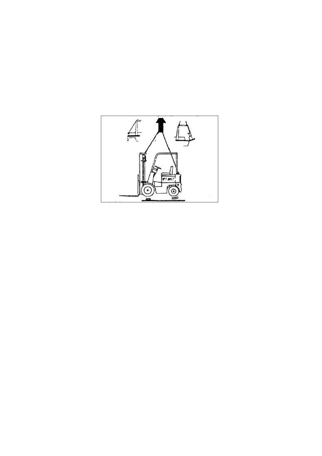
12.Truck’s convey, lifting, towing
Convey
The Fork Lift Truck is designed for material handling only, It is inappropriate for
long-distance transportation. If needed, the Fork Lift Truck must be transported by ship, train
or lorry, of 5T loading. Use a lifting pallet to hoist the truck.
• Use the steel wire ropes to tie the holes in the two side of the outside mast‟s beam and
the rear of truck‟s body, and then use the lifting device to hoist the truck.
Hoist the truck
·Use the steel wire ropes to tie the holes in the two side of the outside mast‟s beam and
the hook of the counter balance, and then use the lifting device to hoist the truck. The steel
wire rope attach to the counterweight should through the safeguard gap, and make the
safeguard not be distorted.
Warning
·When hoist the truck, don‟t coil the overhead guard with the steel wire.
·The steel wire ropes and the lifting device must be very firm to support the truck because
the truck is very heavy.
·Don‟t lift the truck by hoist the overhead guard.
·When lifting the truck, don‟t take yourself below the truck.
Towing
·The towing rod on the bottom of the counter balance is used to pull and drag the truck.
Loosen the brake lever and turn off key switch.
Set switch lever to neutral position
Warning
a. Don‟t tie the steel wire ropes on the unfixed position.
b. Don‟t carry a load to steel wire ropes suddenly.
c. The truck would be damaged if you tow it with the electric lock working.
51

13.Parameters
Parameters of CPD10/15/18J
NO.
Item
Units
CPD10J
CPD15J
CPD18J
1
Ratio capacity
kg
1000
1500
1800
2
Load centre
mm
500
500
500
Max.
mm
3000
3000
3000
3
Lifting height
Free
mm
135
135
135
Max.
Lifting
4
Fully loaded
mm/s
290
290
270
velocity
5
Tilting angle
front/rear
°
5/10
5/10
5/10
Max. Traveling
6
Fully loaded
mm/s
12
12
12
velocity
Max. Crawling
7
Fully loaded
%
13
13
13
slope
8
Turning radius
Min.
mm
1780
1780
1815
Ground
9
Min.
mm
110
110
110
clearance
Stopping
10
Max.
m
2.5
2.5
2.5
distance
L
mm
2080
2080
2115
11
Overall Dimension
W
mm
1090
1090
1138
H
mm
2075
2075
2075
Include
12
Weight (self)
kg
2770
2940
3090
battery
Standard
V/Ah
48/420
48/420
48/420
13
Battery
Optional
V/Ah
48/480
48/480
48/480
Driven
kW
8
8
8
14
Motor
Lifting
kW
7.8
7.8
7.8
Type
MOSFET
MOSFET
MOSFET
Tow
Danaher
Danaher
Danaher
15
Controller
Manufacturer
Lifting
Danaher
Danaher
Danaher
Front ×2
6.00-9/2
6.00-9/2
21×8-9/2
16
Tyre
Rear ×2
5.00-8/2
5.00-8/2
5.00-8/2
52

Parameters of CPD10/15/18JC1
NO.
Item
Unit
CPD10JC1
CPD15J C1
CPD18J C1
1
Ratio capacity
kg
1000
1500
1800
2
Load centre
mm
500
500
500
Max.
mm
3000
3000
3000
3
Lifting height
Free
mm
135
135
135
Max.
Lifting
4
Fully loaded
mm/s
290
290
270
velocity
5
Tilting angle
front/rear
°
5/10
5/10
5/10
Max. Traveling
6
Fully loaded
mm/s
12
12
12
velocity
Max. Crawling
7
Fully loaded
%
13
13
13
slope
8
Turning radius
Min.
mm
2090
1780
1815
Ground
9
Min.
mm
110
110
110
clearance
Stopping
10
Max.
m
2.5
2.5
2.5
distance
L
mm
/
2080
2115
11
Overall Dimension
W
mm
1090
1090
1138
H
mm
2075
2075
2075
Include
12
Weight (self)
kg
/
2940
3090
battery
Standard
V/Ah
48/420
48/420
48/420
13
Battery
Optional
V/Ah
48/480
48/480
48/480
Driven
kW
6.8
6.8
6.8
14
Motor
Lifting
kW
8.2
8.2
8.2
Type
MOSFET
MOSFET
MOSFET
Tow
CURTIS
CURTIS
CURTIS
15
Controller
Manufacturer
Lifting
CURTIS
CURTIS
CURTIS
Front ×2
6.00-9/2
6.00-9/2
21×8/2
16
Tyre
Rear ×2
5.00-8/2
5.00-8/2
5.00-8/2
53

Parameters of CPD10/15/18JD1
NO.
Item
Unit
CPD10JD1
CPD15JD1
CPD18JD1
1
Ratio capacity
kg
1000
1500
1800
2
Load centre
mm
500
500
500
Max.
mm
3000
3000
3000
3
Lifting height
Free
mm
135
135
135
Max.
Lifting
4
Fully loaded
mm/s
290
290
270
velocity
5
Tilting angle
front/rear
°
5/10
5/10
5/10
Max. Traveling
6
Fully loaded
mm/s
12
12
12
velocity
Max. Crawling
7
Fully loaded
%
13
13
13
slope
8
Turning radius
Min.
mm
2090
1780
1815
Ground
9
Min.
mm
110
110
110
clearance
Stopping
10
Max.
m
2.5
2.5
2.5
distance
L
mm
/
2080
2115
11
Overall Dimension
W
mm
1090
1090
1138
H
mm
2075
2075
2075
Include
12
Weight (self)
kg
/
2940
3090
battery
Standard
V/Ah
48/420
48/420
48/420
13
Battery
Optional
V/Ah
48/480
48/480
48/480
Driven
kW
8
8
6.8
14
Motor
Lifting
kW
7.8
7.8
8.2
Type
MOSFET
MOSFET
MOSFET
Tow
Danaher
Danaher
CURTIS
15
Controller
Manufacturer
Lifting
Danaher
Danaher
CURTIS
Front ×2
6.00-9/2
6.00-9/2
21×8/2
16
Tyre
Rear ×2
5.00-8/2
5.00-8/2
5.00-8/2
54

Parameters of CPD20/25/30J
No.
Item
Unit
CPD20J
CPD25J
CPD30J
1
Ratio capacity
kg
2000
2500
3000
2
Load centre
mm
500
500
500
Max.
mm
3000
3000
3000
3
Lifting height
Free
mm
140
145
145
Max.
Lifting
Fully
4
mm/s
250
250
230
velocity
loaded
front/rea
5
Tilting angle
°
5/10
5/10
5/10
r
Max.
Traveling
Fully
6
mm/s
12
12
13
velocity
loaded
Fully
7
Max. Crawling slope
%
13
10
13
loaded
8
Turning radius
Min.
mm
2090
2090
2230
9
Ground clearance
Min.
mm
120
120
120
10
Stopping distance
Max.
m
2.5
2.5
2.5
L
mm
2275
2325
2490
11
Overall Dimension
W
mm
1265
1265
1240
H
mm
2100
2100
2100
Include
12
Weight (self)
kg
3800
4020
5050
battery
Standar
V/Ah
48/630
48/630
80/500
d
13
Battery
Optional
V/Ah
48/700
48/700
/
Driven
kW
7
7
10
14
Motor
Lifting
kW
8.6
8.6
10
Type
MOSFET
MOSFET
MOSFET
15
Controller
Tow
CURTIS
CURTIS
CURTIS
Manufact
urer
Liftin
CURTIS
CURTIS
CURTIS
g
Front ×2
23×9-10/2
23×9-10/2
23×9-10/2
16
Tyre
Rear ×2
18×7-8/2
18×7-8/2
18×7-8/2
55

Parameters of CPD20/25/30/35JC1
No.
Item
Unit
CPD20JC1
CPD25JC1
CPD30JC1
CPD35JC1
1
Ratio capacity
kg
2000
2500
3000
3500
2
Load centre
mm
500
500
500
500
Max.
mm
3000
3000
3000
3000
3
Lifting height
Free
mm
140
145
145
145
Max.
Lifting
Fully
4
mm/s
250
250
230
210
velocity
loaded
front/rea
5
Tilting angle
°
5/10
5/10
5/10
5/10
r
Max.
Traveling
Fully
6
mm/s
12
12
13
13
velocity
loaded
Fully
7
Max. Crawling slope
%
13
10
13
12
loaded
8
Turning radius
Min.
mm
2090
2090
2230
2310
9
Ground clearance
Min.
mm
120
120
120
120
10
Stopping distance
Max.
m
2.5
2.5
2.5
2.5
L
mm
2275
2325
2490
2570
11
Overall Dimension
W
mm
1265
1265
1265
1302
H
mm
2100
2100
2100
2100
Include
12
Weight (self)
kg
3800
4020
5050
5400
battery
Standar
V/Ah
48/630
48/630
80/500
80/500
d
13
Battery
Optional
V/Ah
48/700
48/700
/
/
Driven
kW
9.1
9.1
11.75
11.75
14
Motor
Lifting
kW
8.6
8.6
10
10
Type
MOSFET
MOSFET
MOSFET
MOSFET
15
Controller
Tow
CURTIS
CURTIS
CURTIS
CURTIS
Manufact
urer
Liftin
CURTIS
CURTIS
CURTIS
CURTIS
g
Front ×2
23×9-10/2
23×9-10/2
23×9-10/2
23×10-12/2
16
Tyre
Rear ×2
18×7-8/2
18×7-8/2
18×7-8/2
18×7-8/2
56

Parameters of CPD20/25/30/35JC2
No.
Item
Unit
CPD20JC2
CPD25JC2
CPD30JC2
CPD35JC2
1
Ratio capacity
kg
2500
2500
3000
3500
2
Load centre
mm
500
500
500
500
Max.
mm
3000
3000
3000
3000
3
Lifting height
Free
mm
145
145
145
145
Max.
Lifting
Fully
4
mm/s
250
250
230
210
velocity
loaded
front/rea
5
Tilting angle
°
5/10
5/10
5/10
5/10
r
Max.
Traveling
Fully
6
mm/s
12
12
13
13
velocity
loaded
Fully
7
Max. Crawling slope
%
10
10
13
12
loaded
8
Turning radius
Min.
mm
2090
2090
2230
2310
9
Ground clearance
Min.
mm
120
120
120
120
10
Stopping distance
Max.
m
2.5
2.5
2.5
2.5
L
mm
2325
2325
2490
2570
11
Overall Dimension
W
mm
1265
1265
1265
1302
H
mm
2100
2100
2100
2100
Include
12
Weight (self)
kg
4020
4020
5050
5400
battery
Standar
V/Ah
48/630
48/630
80/500
80/500
d
13
Battery
Optional
V/Ah
48/700
48/700
/
/
Driven
kW
9.1
9.1
11.75
11.75
14
Motor
Lifting
kW
8.6
8.6
Type
MOSFET
MOSFET
MOSFET
MOSFET
15
Controller
Tow
CURTIS
CURTIS
CURTIS
CURTIS
Manufact
urer
Liftin
CURTIS
CURTIS
CURTIS
CURTIS
g
Front ×2
23×9-10/2
23×9-10/2
23×9-10/2
23×10-12/2
16
Tyre
Rear ×2
18×7-8/2
18×7-8/2
18×7-8/2
18×7-8/2
57

Parameters of CPD20/25/30/ 35J D1
CPD20J
No.
Item
Unit
CPD25J D1
CPD30J D1
CPD35J D1
D1
1
Ratio capacity
kg
2000
2500
3000
3500
2
Load centre
mm
500
500
500
500
Max.
mm
3000
3000
3000
3000
3
Lifting height
Free
mm
140
145
145
145
Max.
Lifting
Fully
4
mm/s
250
250
250
210
velocity
loaded
front/rea
5
Tilting angle
°
5/10
5/10
5/10
5/10
r
Max.
Traveling
Fully
6
mm/s
14
12
14.5
13
velocity
loaded
Fully
7
Max. Crawling slope
%
14
13
15
11
loaded
8
Turning radius
Min.
mm
2040
2090
2230
2310
9
Ground clearance
Min.
mm
120
120
120
120
10
Stopping distance
Max.
m
2.5
2.5
2.5
2.5
L
mm
2275
2325
2490
2570
11
Overall Dimension
W
mm
1265
1265
1265
1302
H
mm
2100
2100
2100
2100
Include
12
Weight (self)
kg
3800
4180
5050
5460
battery
Standar
V/Ah
48/630
48/630
80/500
80/500
d
13
Battery
Optional
V/Ah
48/700
48/700
/
/
Driven
kW
10.5
10.5
10.6
10.6
14
Motor
Lifting
kW
11
11
12.8
12.8
Type
MOSFET
MOSFET
MOSFET
MOSFET
15
Controller
Tow
Danaher
Danaher
Danaher
Danaher
Manufact
urer
Liftin
Danaher
Danaher
Danaher
Danaher
g
Front ×2
23×9-10/2
23×9-10/2
23×9-10/2
23×10-12/2
16
Tyre
Rear ×2
18×7-8/2
18×7-8/2
18×7-8/2
18×7-8/2
58

Parameter of CPD40/45/50J D1
No.
Item
Unit
CPD40J D1
CPD45J D1
CPD50J D1
1
Ratio capacity
kg
4000
4500
5000
2
Load centre
mm
500
500
500
Max.
mm
3000
3000
3000
3
Lifting height
Free
mm
145
150
150
Max.
Lifting
Fully
4
mm/s
260
260
230
velocity
loaded
front/rea
5
Tilting angle
°
6/12
6/12
6/12
r
Max.
Traveling
Fully
6
mm/s
13.5
13.5
13
velocity
loaded
Fully
7
Max. Crawling slope
%
14
14
13
loaded
8
Turning radius
Min.
mm
2650
2650
2650
9
Ground clearance
Min.
mm
219
219
226
10
Stopping distance
Max.
m
2.5
2.5
2.5
L
mm
3015
3015
3015
11
Overall Dimension
W
mm
1380
1380
1380
H
mm
2280
2280
2280
Include
12
Weight (self)
kg
6550
6800
7250
battery
Standar
V/Ah
80/700
80/700
80/700
d
13
Battery
Optional
V/Ah
/
/
/
Driven
kW
16.6
16.6
16.6
14
Motor
Lifting
kW
25.4
25.4
25.4
Type
MOSFET
MOSFET
MOSFET
15
Controller
Manufact
Danaher
Danaher
Danaher
urer
Front ×2
250-15-16/2
250-15-16/2
250-15-16/2
16
Tyre
Rear ×2
7.00-12-12/2
7.00-12-12/2
7.00-12-12/2
59

Parameter of CPD40/45/50J C2
No.
Item
Unit
CPD40J C2
CPD45J C2
CPD50J C2
1
Ratio capacity
kg
4000
4500
5000
2
Load centre
mm
500
500
500
Max.
mm
3000
3000
3000
3
Lifting height
Free
mm
145
150
150
Max.
Lifting
Fully
4
mm/s
260
260
260
velocity
loaded
front/rea
5
Tilting angle
°
6/12
6/12
6/12
r
Max.
Traveling
Fully
6
mm/s
13.5
13.5
13
velocity
loaded
Fully
7
Max. Crawling slope
%
14
14
13
loaded
8
Turning radius
Min.
mm
2650
2650
2650
9
Ground clearance
Min.
mm
219
219
226
10
Stopping distance
Max.
m
2.5
2.5
2.5
L
mm
3015
3015
3015
11
Overall Dimension
W
mm
1380
1380
1380
H
mm
2310
2310
2310
Include
12
Weight (self)
kg
6550
6800
7200
battery
Standar
V/Ah
80/700
80/700
80/700
d
13
Battery
Optional
V/Ah
/
/
/
16.6@3100r
16.6@3100r
16.6@3100rp
Driven
kW
pm
pm
m
14
Motor
25.4@1620
25.4@1620
25.4@1620
Lifting
kW
rpm
rpm
rpm
Type
MOSFET
MOSFET
MOSFET
15
Controller
Manufact
CURTIS
CURTIS
CURTIS
urer
Front ×2
250-15-16/2
250-15-16/2
250-15-16/2
16
Tyre
Rear ×2
7.00-12-12/2
7.00-12-12/2
7.00-12-12/2
60
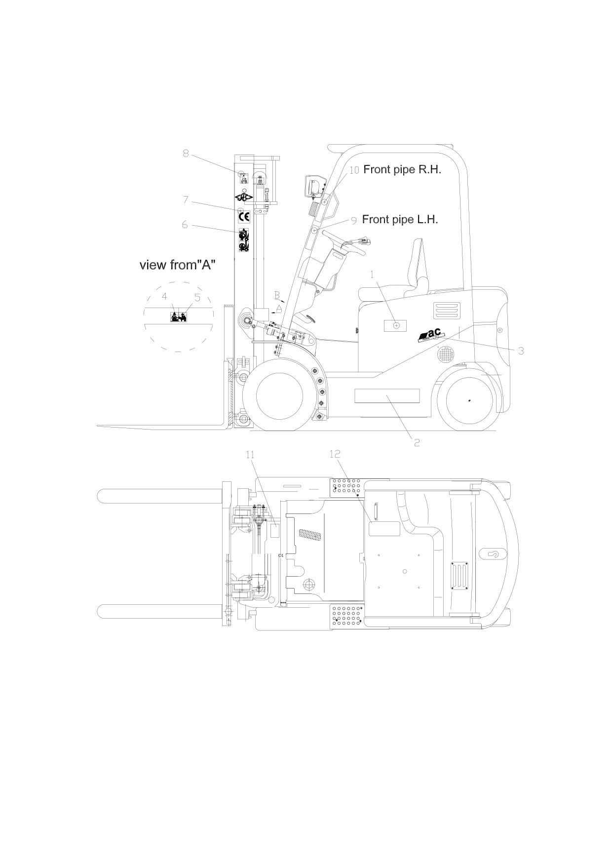
14.Scutcheon
There are many scutcheons and labels on the different position of the truck.
61
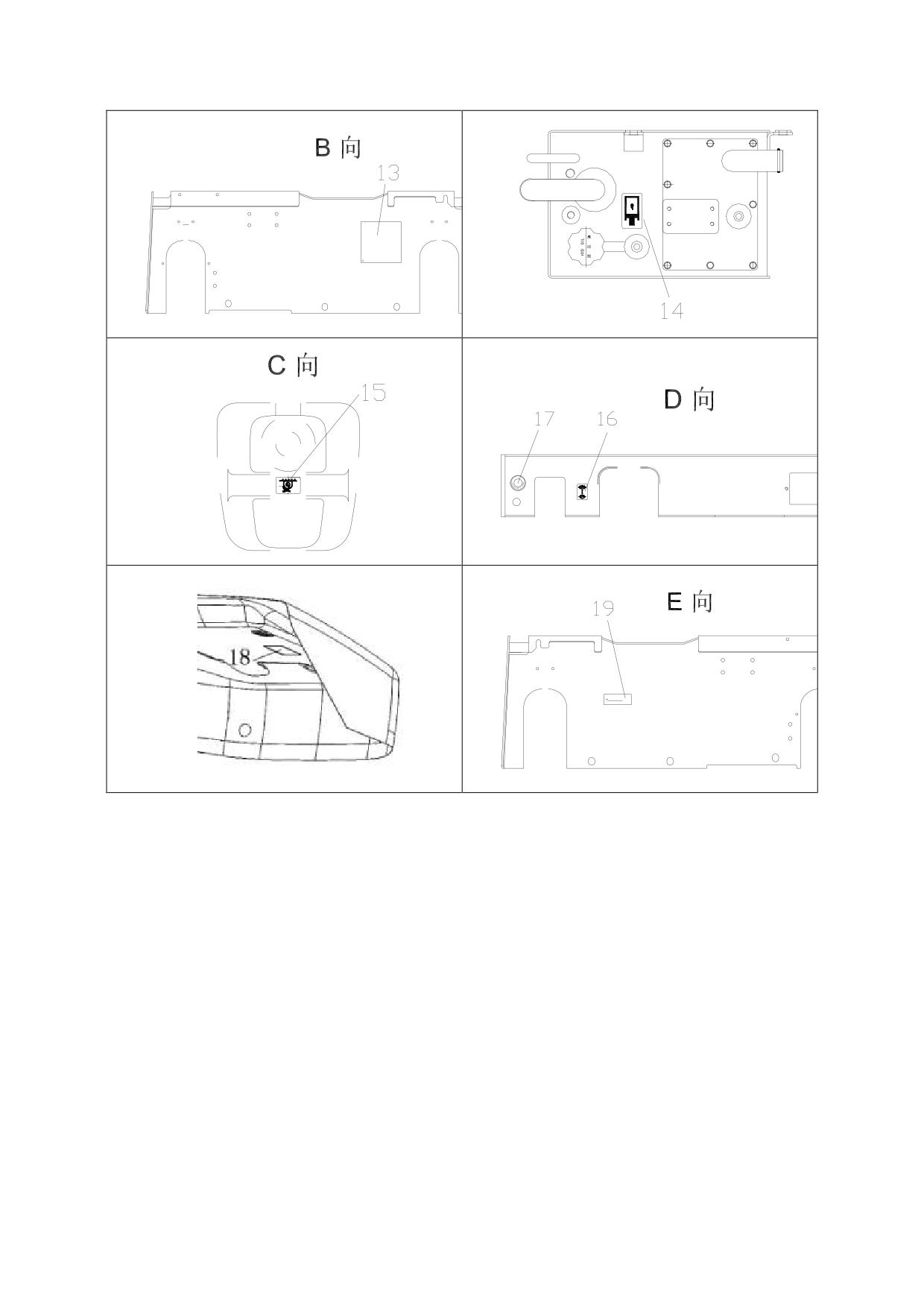
1.tonnage label
2. typeface label
3. ac label
4. danger label
5.danger label
6. danger label
7. CE label
8. hanging label
9. danger label
10. danger label
11. load curve scutcheon
12. warning label
13. product nameplate
14. hydraulic oil label
15.tight point label
16.hand brake label
17. urgent stop label
18. noise label
19.fuse label
62
1、tonnage label
The inner and outer mast, fork frame are
all lifting slip parts. The hands are not
allowed to reach the place between the
inner and outer mast.
If the part needs to be check or repaired,
the inspection and repair should be carried
out after shutting off the power. Nobody
The word “30”means the rated load is 3.0
is allowed on the truck, and the man
ton. If the lifting height increases or adds
outside the truck is not allowed to operate
attachment, the rated load will decrease.
the truck, preventing from accident caused
2、typeface label
by miss operating the mast handle.
6、danger label:adhibit to the outside of
mast
3、ac label(only fro ac motor)
No allowed to stand on or down the mast,
or it is dangerous to your life.
4、danger label (NO entering label)
7、CE label(only for truck exporting to
Europe or option)
Warning: It is dangerous of your life. If
the body is clamped among the mast ,
instrument frame and shield cabane, your
life will be dangerous. If the part needs to
be check or repaired, the inspection and
repair should be carried out after shutting
off the power. Nobody is allowed on the
8、hang label:It shows the hang position
truck, and the man outside the truck is not
and method. When hanging, the rope
allowed to operate the truck, preventing
should not touch the light and even destroy
from accident caused by miss operating the
it.
mast handle.
LIFT METHOD
5、danger label
63
9、10 danger label
13、product nameplate
WARNING
14、hydraulic oil label
11、load curve scutcheon
It shows relation among the position of
the load center, max. load and max. lifting
height.
If it has side moving and attachment,
the load decreases. If the lifting height
15、tight point label(only for truck
increases, the load decreases. Before
exporting to Europe or option)
loading, check whether the load and the
center distance of load are in the allowed
range show in the diagram of load capacity.
If the shape of load is complicated, make
the most heavy part place in the center of
the fork and approach the stop fork frame.
16、hand brake label(only for truck
exporting to Europe or option)
12、warning label
17、urgent stop label
W A R N I N G
SERIOUS OR FATAL INJURY MAY RESULT TO YOURSELF OR OTHERS IF NOT FOLLOWED
This lift truck should not be operated by anyone who is not authorized and properly trained.
Read the Operators Manual and all warnings carefully,and make yourself familiar with your lift truck.
Operator's Manual and Service Manual are supplied with this truck or available from our forklift truck dealers.
Inspect and check your lift truck daily before and after use.Do not operate faulty or damaged lift trucks.
Repair work should be done by authorized and trained persons only.
To protect from falling objects,make sure that the Overhead Guard and Load Backrest Extension are correctly mounted
and in good condition.
Check the capacity of the battery and the condition of all kinds of switch,connecting plug,operating level, pedal,
tyre pressure and fastener.
Starting forklift truck:Realase parking brake and turn on the switch. After moving the shift lever to Forward
(or Reverse), depress the accelerator pedal to start truck. If making an error by procedure, the truck can not start.
When unloading, the weight and diemension should be within the permitted range on the capacity chart. Overload is
prohibited and set the cargo at the center of mast to avoid departure.
When traveling with loading, it is necessary to lift fork up to 300mm, tilt backward most and set the load closed
to the backrest. It is Pohibited to brake and turn suddently when travelling with loading.
Stop the truck steadily, turn the key to OFF position and remove it, move the shift level to "NEUTRAL" and set the
fork to ground.
When hoisting the battery case, it should take by four holes in the each side of the case. It is prohibited to hoist
only by two holes, otherwise, the case will be deformed to damage the battery.
64
18、noise labe(only for truck exporting
to Europe or option)
LWA
19、fuse label(only for truck exporting
to Europe or option)
USE SPECIFIED FUSES ONLY
65
15.The use, assembly and safe rules of attachment
HANGCHA will choose attachment that according with International standard ISO2328《Forklift
pothook fork and install size of carriage》,such as clamp, rotator, paper roll clamp, carrying ram,
side-shifter ect.
1、Attachment use.
(1) Know well the content of nameplate on attachment, read the instruction manual before
Usage.(Especially the manual from attachment company)Before operate the attachment, the people should
be trained and obtain the qualification.
(2) It should be understand the basic capability and operate methods of attachment. Especially the
admit load, lift height, size of cargo and adapt range of attachment.
(3)Operate the multi-functional attachment, such as with side-shifter, clamp or rotator, it is not
allowed that two action at one time. Operate one functional then do another one.
(4)Prohibit the cargo at a high position when truck move with attachment. If the size of cargo is too
big, prohibit the truck move on. Transport the cargeo, make sure that the distance of bottom of cargo and
ground is less than 300mm and mast incline back.
(5)The weight of cargo couldn‟t exceed the limited value of combination carrying capacity of
forklift and attachment. It is not allowed that partial load at high position. It is a short time work for
attachment with side-shifter. Partial load is around 100mm (Above 5 ton (including 5 ton),the side-shifter
movable within 300mm.
(6)In the range of the projection forth 2m of the lower of attachment and cargo, prohibit stand to
avoid the suddenness except the driver position under overhead.
(7)It is not allowed that an emergency brake in moving. Run slowly with load.
(8)Prohibit outside force when attachment working.
(9)It couldn‟t be use at malfeasance situation and overstep normal work range
(10)When the attachment failure, prohibit use without check.
Check and maintenance:
(1)Check the clearance of carriage beam and below catch of attachment if accord the attachment
manual.
(2)Check the rise catch is right on the flute of fork carriage.
(3)Use the auto currency lithic-grease per 500 hours to bearing surface.
(4)If the tighten firmware become flexible.
(5)Check the tie-in of hydraulic pressure loop, if tube attaint. Prohibit use after repair.
(6)Check the drive of attachment timing or turn the component if fray or block, change betimes.
(7)Check each element if in normal under load attachment is work in gear. If not, check the
hydraulic pressure loop, find out the broken part, change air poof or whole loop part.
66
2、Attachment assembly
!Caution
1、Untempered technology licence of our company, any refit at safety and capability to attachment
is strict prohibit.
2、Fact rating load capacity should be the least of rating load capacity, the load capacity of
attachment, colligate load capacity of truck. Generally speaking, the colligate load capacity of
truck is the least. Attachment load capacity just a count value of attachment pressure.
3、Assembly go to in reason, credibility, safety to avoid the attachment glide around carriage in
using.
4、After hang attachment, embed the rise catch block to the gap of top beam, let the offset of
centre line of attachment and carriage is less than 50mm.Otherwise,it will be affect the landscape
orientation stability of forklift.
5、To these attachment with rotating function, such as paper roll clamp, bale clamp, muti-purpose
clamp, drum clamp, it needs to weld chock block in the joint of carriage beam and attachment to
prevent move from side to side in the operation.
6、Assembly the attachment of below catch orientation, it need to adjust the clearance between
below catch and beam of carriage.
67
16.Related safety instruction and standard (for trucks exporting
to Europe or option)
The model by CE certification which according to the following instruction and standard:
DIRECTIVE 2006/42/EC OF THE EUROPEAN PAMENT AND OF THE COUNCIL,
DIRECTIVE 2000/14/EC OF THE EUROPEAN PAMENT AND OF THE COUNCIL,
EN1726-1:1998(Engineering Industry truck safety standardize), EN12053:2001,
EN1175-1:1998, EN13059:2002 coordinate standard.
Main safety factor will be according with DIRECTIVE
2006/42/EC OF THE
EUROPEAN PAMENT AND OF THE COUNCIL and EN1726-1:1998、EN1175-1:1998
standard.
The design and manufacture of electrical element comply with the low voltage standard
2006/95/EC.
Noise will be according with EN12053:2001 and 2000/14/EC.
Vibration parameters are measured according to standards of ISO5349-2:2001,
EN13059:2002, ISO2631-1:1997, and the result meets the requirement of 2002/44/EC.
Electromagnetism compatibility is measured according to standard of EN12895:2000,
and meets the requirement of 2004/108/EC.
68
浙江杭叉工程机械集团股份有限公司
Zhejiang Hangcha Engineering Machinery Co.,Ltd.
地址:杭州市石桥路 398 号 邮编:310022
Website: http//www.zjhc.cn
Add:398 Shi Qiao Road, Hangzhou
310022
E-Mail:sales@zjhc.cn
Tel:+86-571-88926666
Fax: +86-571-88144682
EC DECLARATION OF CONFORMITY
MANUFACTURE
Name:
Zhejiang Hangcha Engineering Machinery Co., Ltd.
Address:
398 Shiqiao Road, Hangzhou 310022, P. R. China
THE TECHNICAL DOCUMENTATION WAS COMPILED BY:
Name:
Address:
Post:
HEREBY DECLARES THAT THE PRODUCT DESCRIBED BELOW:
Description:
Industrial truck -Battery counterbalanced forklift truck with charger
Name:
Electrical forklift truck
Model:
Serial number:
Rated power:
kW
Manufacturing year:
COMPLIES WITH THE PROVISIONS OF THE FOLLOWING EUROPEAN
DIRECTIVES:
2006/42/EC
Machinery Directive
2004/108/EC
EMC Directive
2006/95/EC
LVD Directive
COMPLIES WITH THE PROVISIONS OF THE FOLLOWING HARMONIZED
STANDARDS:
EN 1726-1:1998
Safety of industrial trucks-Self-propelled trucks up to and
+A1:2003
including 10 000 kg capacity and industrial tractors with a
drawbar pull up to and including 20 000 N- Part 1:General
requirements
EN1175-1:1998
Safety of industrial trucks-Electrical requirements-Part 1:
General requirements for battery-powered trucks.
Annex I of Machinery Essential health and safety requirements relating to the
Directive 2006/42/EC
design and construction of machinery
Done
at ZHEJIANG HANGCHA ENGINEERING Name
of
the
(place):
MACHINERY CO.,LTD.
signatory:
On
Title:
Technical Director
(date):
Signature:
69