2019 DFSK Extended Cab Truck. Service Manual
2019 DFSK Extended Cab Truck
- Service Manual -
IDENTIFICATION OF THE VEHICLE
Contents
Ⅰ. Identification of the vehicle
1. Identification of Number
2. VIN
3. Serial Number of the Engine
Ⅱ. Main Technical Parameter
A. Parameter of Mini Bus
1. Engine Parameters
2. General Function Index
3. Fuel consumption
4. Main Parameters
- 2 -
IDENTIFICATION OF THE VEHICLE
5. Main weight Parameters
6. Wheel Alignment Parameters
7. Tyre Air Pressure
8. Capacity Parameters
9. A/C System Parameters
B. Parameter of Mini Truck
1. Engine Parameters
2. General Function Index
3. Fuel consumption
4. Main Parameters
5. Main weight Parameters
6. Wheel Alignment Parameters
- 3 -
IDENTIFICATION OF THE VEHICLE
7. Tyre Air Pressure
8. Capacity Parameters
Ⅲ.Vehicle Devices & Mechanics Operation
1. Door
2. Key
3. Front door window
4. Front door
5. Rear door window
6. Seat
7. Safety Belt
8. Dashboard
9. Fire switch
- 4 -
IDENTIFICATION OF THE VEHICLE
10. Lighting, turning and high/low beam control pole
11. Wiper and cleaner control lever
12. Rear wind window wiper and cleaner switch
13. Horn
14. Emergency light switch
15. Fog light switch
16. Heating system
17. Control Board of heating system
18. Assembled meter
19. Cigar lighter
20. Cigarette ash box
21. Stereo radio
- 5 -
IDENTIFICATION OF THE VEHICLE
22. Tool box
23. Inner light & interior rear view mirror
24. Interior top lamp
25. Outside rear view mirror
26. Sun shading board
27. Safe handgrip
28. Tool kit
29. Brake rod by hand
30. Pedal
31. Shift handlebar
32. Front store house cover
Ⅳ. Operation of the Vehicle
- 6 -
IDENTIFICATION OF THE VEHICLE
1. Running-in
2. Start of the engine
3. Safety driving
4. Brake
5. Economy driving & environmental adaptability
Ⅴ. Guide for Vehicle Operation
1. Fuel
2. Generator strap
3. Compressor belt
4. Engine oil
5. Engine belt
6. Coolant Trademark
- 7 -
IDENTIFICATION OF THE VEHICLE
7. Thermostat
8. Transmission oil
9. Gasoline filter & oil supply tube & oil return tube
10.Air cleaner
11.Spark plug
12.Oil sprayer
13.Throttle valve block
14.Three-way converter
15.Electric fuel pump
16.Steering operation
17.Clutch pedal
18.ABS
- 8 -
IDENTIFICATION OF THE VEHICLE
19.Brake system
20.Tyre
21.Battery
22.Fuse
23.Air window cleaning liquid
24.Replacement of Bulb
25.ECU
26.Ignition timing
27.Usage of Jack
28.Extinguisher
29.Triangle warning plate
30.Operating controller
- 9 -
IDENTIFICATION OF THE VEHICLE
31.Turning over and side
Ⅵ . Check & Maintenance Service
1. Daily inspection
2. Regular check and maintenance
3. Regular maintenance period and items
4. Signs for maintenance
5. Maintenance
Ⅶ. Analyzing & Eliminating the Malfunction
1. Malfunction of engine system
2. Clutch Problems
3. Malfunction of transmission
4. Malfunction of differential gear
- 10 -
IDENTIFICATION OF THE VEHICLE
5. Malfunction of steering system, wheel and tyre system
6. Warm braw system failure
7. A/C system failure
8. Brake system failure
9. ABS system failure
10.Power system failure
11.Variety of lamps, light system failure, headlight failure
Ⅷ . Disposition of Emergency
1. Starting system not work
2. Instruction of storage battery
3. Overheating of engine
4. Traction of vehicle
- 11 -
IDENTIFICATION OF THE VEHICLE
Ⅸ. Maintenance of the Vehicle
1. Cleanness of the vehicle inside vinyl plastics
2. Cleanup & Wax of the Vehicle’s Outer Part
- 12 -
IDENTIFICATION OF THE VEHICLE
I.Identification of the Vehicle
- 13 -
DENTIFICATION OF THE VEHICLE
1. Identification of Number
2. VIN
3. Serial Number of the Engine
There are two VINs, one is on the
The serial number of the Engine
EQ 6 36 0 □□
aluminum plate which is on the right
should be marked on the convexity of the
front side of the Meter, and the other is
rear lower part of the right cylinder.
A B C D E
on the body which is under the front row
right side seat.
A : Self-Stipulate Code
On the Meter Board
B: Vehicle Catagory Number
On the instrument
C: Main Parameter Code
D: Serial Number of the Product
E: Self-Stipulate Code
2) The VIN should be marked on the side
of the frame beam which is under the seat
that beside the driver’s, and above the
Meter Board and on the nameplate.
2
DENTIFICATION OF THE VEHICLE
Ⅱ. Main Technical Parameter
3
DENTIFICATION OF THE VEHICLE
A. Parameter of Mini Bus
1.Engine Parameters
Refer to the engine specification along with the vehicle
2. Common performance parameter
DFSK MINI BUS/SPECIAL BUS
Items
Unit
EQ636×
EQ638×
EQ640×
EQ641×
EQ639×
EQ502×
××series
××series
××series
××series
××series
××series
100,110,115,120,
102,105,
Max Speed
Km/h
100,105,120
110,125
125
125
Max Climbing
%
≥30
Capacity
(50km/h)Brake
m
≤20
Distance(full load)
Min Turning
m
≤9
≤9.8
≤10.8
≤9.8
≤10
≤9.8
Diameters(m)
4
Main Technical Parameter of the Complete Vehicle
3. Fuel Consumption
DFSK MINI BUS AND SPECIALLY SELECTED ENGINE
Items
Unit
EQ474i/EQ474i-30
EQ465i2-30/EQ465i-21/AF10-06/EQ466i-30
BG13-20
Fuel Consumption
L/100
(under limited
≤6.2
≤6.5
km
condition)
Note:As to the different practical condition, the real fuel consumption will be a little higher than the value
above
4. Main demension
DFSK MINI BUS/SPECIAL BUS
EQ640×
EQ641×
EQ502×
Items
Unit
EQ636××
EQ638××
EQ639××
××
××
××
×series
×series
×series
series
series
series
Total Length
mm
3640
3795
4040
4070
3905
3795
Total Wide
mm
1560
1635
1560
Total Height
2070,
mm
1925
2105
1950
(Empty load)
2160
Wheel Base
mm
2360
2515
2760
2515
5
Main Technical Parameter of the Complete Vehicle
FR. Tread
mm
1310
1410
1310
RR. Tread
mm
1310
1410
1310
FR Suspension
mm
555
570
555
RR. Suspension
mm
725
1000
820
725
5. Main Weight Parameters
DFSK MINI BUS/SPECIAL BUS
EQ636
EQ640
EQ639
Items
Unit
EQ641×××
EQ502×××
×××
EQ638×××series
×××
×××
series
series
series
series
series
Curb
1000,1015,1020,
kg
985,970
1000,1010,1015,1030
1050
1130,1145,1120
1100
Weight
1030
Total
1605,
1400,1415,1595,
kg
1565
1400,1595,1610
1710
1980
Weight
1800
1610
Seating
Capacity
人
2-8
5-8
5-11
2-8
5-7
2
(Include
Driver)
6. Wheel Alignment Parameters
DFSK MINI BUS/SPECIAL BUS
Items
Unit
EQ636××
EQ638××
EQ640××
EQ641××
EQ639××
EQ502×
×series
×series
×series
×series
×series
××
6
Main Technical Parameter of the Complete Vehicle
series
Toe-in
mm
0~5
Tire camber
42′±
1°30’
1°30’
angle
30′
Master pin
9°28′±
(°)
8°
8°
inclination angle
30′
Master pin caster
2°50′±
2°30’
2°30’
angle
30′
7. Tyre Air Pressure
DFSK MINI BUS MODELS
EQ636×
EQ638×
EQ640×
EQ641×
Item
Unit
EQ639×××
××
××
××
××
EQ502×××Series
Series
Series
Series
Series
Series
Zero
200
200(165/70R14,
kPa
200(165/70R14,155R13LT)
Front
load
(175/80R14)
155R13LT)
tire
Full
200
240(165/70R14,
kPa
240(165/70R14,155R13LT)
load
(175/80R14)
155R13LT)
Zero
220
240(165/70R14,
kPa
240(165/70R14,155R13LT)
load
(175/80R14)
155R13LT)
Rear
tire
Full
250
280(165/70R14),300
kPa
280(165/70R14),300(155R13LT)
load
(175/80R14)
(155R13LT)
7
Main Technical Parameter of the Complete Vehicle
8. Volume Parameters
DFSK MINI BUS AND SPECIALLY SELECTED ENGINE
Item
Unit
EQ465i-21/EQ465i2-30
AF10-06
EQ474i/EQ474i-30
BG13-20
EQ466i-30
Cool system of engine
L
4.8
5.3
Lubrication system of engine
L
3
3.2
4.2
4.2~4.5
Fuel tank
L
40,50(Only for EQ6390PF Series)
Lubrication oil of transmission box
L
1.2
1.3
1.3
1.3~1.5
Lubrication oil of rear axle
L
1.2
Braking oil
L
0.6
9.A/C System Parameters
DFSK MINI BUS/ SPECIAL BUS
EQ636
EQ638
EQ640
EQ639
EQ502
Items
Unit
××
××
××
EQ641×××
××
××
×
×
×
Series
×
×
Series
Series
Series
Series
Series
Cooling Ability
W
4250
2870
4250
Cooling Wind Speed
M3/h
400
300
400
8

Main Technical Parameter of the Complete Vehicle
Compressor consuption
W(Nc2000r/min)
2.13
1.58W(Nc1800r/min)
2.13
Idle
Automatically
r/min
950±50(465 engine),900±50(474 engine)
Increase
A/C water
Temperature
℃
110
Protection
Engine water
Control
Temperature
℃
90
Parameter
Protection
High Pressure
MPa
3.2
Protection
Low Pressure
MPa
0.2
Protection
Over-heating
℃
150±5
150±5
150±5
Protection
Note:1. EQ636×××series include:EQ6360LF;
EQ638×××series include:EQ6380LF;
EQ640×××series include:EQ6400LF;
EQ641×××series include:EQ6410LF;
EQ639×××series include: EQ6390PF22Q;
9
Main Technical Parameter of the Complete Vehicle
EQ502×××series include:EQ5021XXYF。
2. In order to meet the demands of the markets, the newly developed EQ636XXXseries, EQ638XXXseries
and EQ640XXXseries adopt elective materials such as the front bumper bar (including rear bumper bar with
those mini vans converted from mini buses), dashboard, luminaries, side-mirror, decoration boards and seat
fabric. The appearance of the vehicle may not be the same with the specifications listed in this manual.
Please refer to the practical dimension of the vehicle.
10
Main Technical Parameter of the Complete Vehicle
B. Parameter of Mini Truck
11
Main Technical Parameter of the Complete Vehicle
1. Engine Parameter
Refer to the engine manual distributed with the vehicle.
2. Common performance parameter
DFSK truck and other special vehicle models
EQ1021NF
EQ1021TF
×
EQ502 × × × ×
EQ502 × × ×
EQ502 × × × ×
Item
Unit
EQ1020TF
EQ1021GF24Q7
Truck (Double
××
××
×××
××
Truck
Truck
cabin)
Widened truck
Van
Van
Special truck
Km/
Max Speed
100
100,120
105,125
100,120
100
100,120
100,120
h
Gradeability
%
≥30
Braking
distance with
m
≤20
the speed of
50 km/h
Min turning
m
≤9.8,≤10.8
≤10
≤9.8
≤10
diameter
Fuel
L/100
consumption
≤6.2,≤6.5
≤6.8,≤6.5,≤6.2
≤6.2,≤6.5
≤6.5
km
per 100 km
Note: the actual fuel consumption is normally higher than the specification listed in the form.
12
Main Technical Parameter of the Complete Vehicle
3. Fuel Consumption
DFSK TRUCK AND SPECIALLY SELECTED ENGINE
Items
Unit
EQ465i2-30/EQ465i-21/AF10-06/EQ466i-30
EQ474i/EQ474i-30BG13-20
Fuel Consumption
L/100
≤6.2
≤6.5
(under limited condition)
km
Note:As to the different practical condition, the real fuel consumption will be a little higher than the value above
4. Main Dimension
DFSK truck and other special vehicle models
EQ1021NF
EQ1021TF × ×
EQ502 × × ×
EQ502××××
EQ502××××
EQ1021GF24Q
Item
Unit
EQ1020TF
Truck (Double
×
×××
××
××
7
Truck
cabin)
Widened truck
Van
Van
Special truck
Truck
4390,4150,
3795,4070,
3795,4150,
Length
mm
3980,4160, 4410
4538
4335,4220,4150
4280
3980,
4040
4185,4220
Width
mm
1560
1635
1560
Height (zero
mm
1825
1860
1890
1925,2105
2150
2160,2490
1850
load)
13
Main Technical Parameter of the Complete Vehicle
Wheelbase
mm
2515,2760
2515,2760
2760
2515
2760
Front tread
mm
1310
1415
1310
Rear Tread
mm
1310
1410
1310
555/1080
Front
555/725,
,
555/910,
555/725,
555/1265
suspension/
555/1080,
mm
555/1075
555/1090,
570/1208
555/1000,
555/1150
580
Rear
555/1115,
,555/880
555/1095
555/1000
555/1080
suspension
555/1150
2700,
内尺寸
2460,
2460,2370,1650
1650,2310,2460
1390,1650, 1900,
2800×1540×
Inner size of
mm
2290×
--
×1440,1430,
×1330,1400,
940
×1440× 340,430
350
carriage
1440,
1400×1350
1440×340,430
340
5. Main weight parameter
DFSK truck and other special vehicle models
Item
Unit
EQ1020TF
EQ1021NF
EQ1021TF×××
EQ1021GF24Q7
Truck
Truck with double cabin
Widened truck
Truck
Curb weight
Kg
910,900,880
965,1030
990
970
Total weight
kg
1810,1530
1780 ,1845
1920
1700
Passenger
capacity/
2/790,2/800
人/kg
2+3/490 ,2+3/490
2/800
2/600
Loading
2/490
capacity
14
Main Technical Parameter of the Complete Vehicle
6. Wheel Alignment parameter
DFSK truck and other special vehicle models
Item
Unit
EQ1020TF
EQ1021NF
EQ1021TF×××
EQ1021GF24Q7
Truck
Truck with double cabin
Widened truck
Truck
Toe-in
mm
0~5
Tire camber
1°30’
42′±30′
1°30’
angle
Master pin
inclination
8
9°28′±30′
8
(°)
angle
Master pin
2°30’
2°50′±30′
2°30’
caster angle
7. Tire air pressure
DFSK truck and other special vehicle models
EQ1020T
EQ1021NF
EQ1021TF × ×
EQ502××
EQ502××
EQ502 × ×
Item
Unit
EQ1021GF24Q7
F
Truck (Double
×
××××
××××
××××
Truck
Truck
cabin)
Widened truck
Van
Van
Special truck
Zero
180(165/70R14)
kPa
20(165/70R14,155R13LT)
200(185R14LT)
200(165/70R14,155R13LT)
Front
load
200(165R13LT,155R13LT)
tire
Full
220(165/70R14)
kPa
24(165/70R14,155R13LT)
220(185R14LT)
240(165/70R14,155R13LT)
load
240(165R13LT,155R13LT)
Zero
200(165/70R14)
kPa
24(165/70R14,155R13LT)
220(185R14LT)
240(165/70R14,155R13LT)
load
220(165R13LT,155R13LT)
Rear
250(165/70R14
,
tire
Full
280(165/70R14
,300
kPa
240(185R14LT)
280(165/70R14
,300(155R13LT)
300(165R13LT
,
load
(155R13LT)
375(155R13LT)
15
Main Technical Parameter of the Complete Vehicle
8. Volume parameter
Item
Elective engines for DFSK truck and special truck models
Unit
EQ465i2-30/EQ465i-21
AF10-06
EQ474i-30/EQ474i
BG13-20
Cool system of
L
4.8
5.3
engine
Lubrication
L
3
3.2
4.2
4.2~4.5
system of engine
Fuel tank
L
40
Lubrication oil of
L
1.2
1.3
1.3
1.3~1.5
transmission box
Lubrication oil of
L
1.2
rear axle
Braking oil
L
0.6
Note: 1. EQ1020TF truck series includes: EQ1020TF 2.3M,2.5M,2.7M;
EQ1021NF double cabin truck series includes: EQ1021NF 1.4M 1.7M 2.0M
EQ1021TF widened truck series includes: EQ1021TF22QN11 2.9M
EQ1021GF24Q7 Truck series includes: EQ1021GF24Q7 2.3,2.5M
EQ502×××××× van series includes: EQ5021XXYF,EQ5024XXYF4, truck with aluminium alloy carriage, refrigerator truck,
dumper truck, vender truck
2. In order to meet the demands of the markets, the newly developed truck series adopts elective materials such as the front bumper bar
(including rear bumper bar with those mini vans converted from mini buses), dashboard, luminaires, side-mirror, decoration boards and seat
fabric. The appearance of the vehicle may not be the same with the specifications listed in this manual. Please refer to the practical dimension of
the vehicle.
16
Main Technical Parameter of the Complete Vehicle
Ⅲ、Vehicle Devices & Mechanics Operation
17
Main Technical Parameter of the Complete Vehicle
1. Door
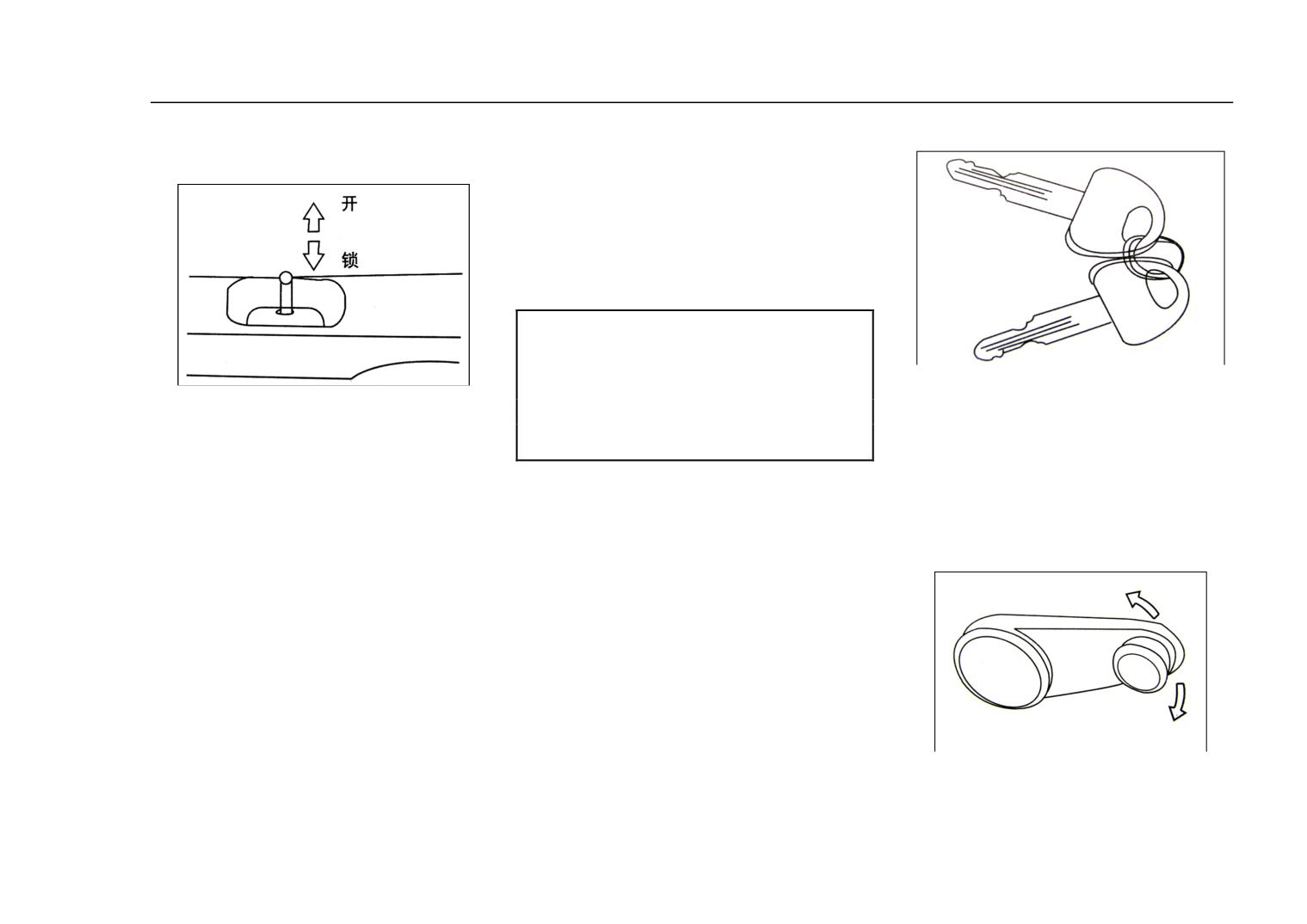
While locking the front and back door
Open
without key outside the vehicles, the
locking buttion shall be pressed down
Lock
while the door is open, and pull up the
window, then close the door.
Note:
The door shall be locked well,
This vehicle is with two keys,
and the locking button shall be pressed
Inside the Vehicle:
please keep one in a safe place for
down while driving to avoid any
spare use.The other can be used for
All the doors can be locked by
unexpected open of the door.
ignition switch, front door and back
pressing down the locked button. After
Back door:
door.
Please keep the key along with you
that, the door can not be open either
While locking the back door, the
at any time.
inside or outside the vehicle. When
back door shall be closed first and
3. Front Door Window
then turn the key clockwisedly. While
open it, pull the locked button upward.
open the door, turn the key
Front Door:
counter-clockwisedly and open the
The front door can be open and locked
door.
by key. The locking button rises while
2. Key
open, and is down while locked.
Back Door:
The door windows of front door are of
The locking button rises while
two types, manual and electric.
open, and is down while locked.
When by hand, there is handlebar
10
Main Technical Parameter of the Complete Vehicle
on the inner side of the door. Turn the
handlebar
clockwise
or
counter-clockwise, the door window
will come up or come down.
4.
Front
Door
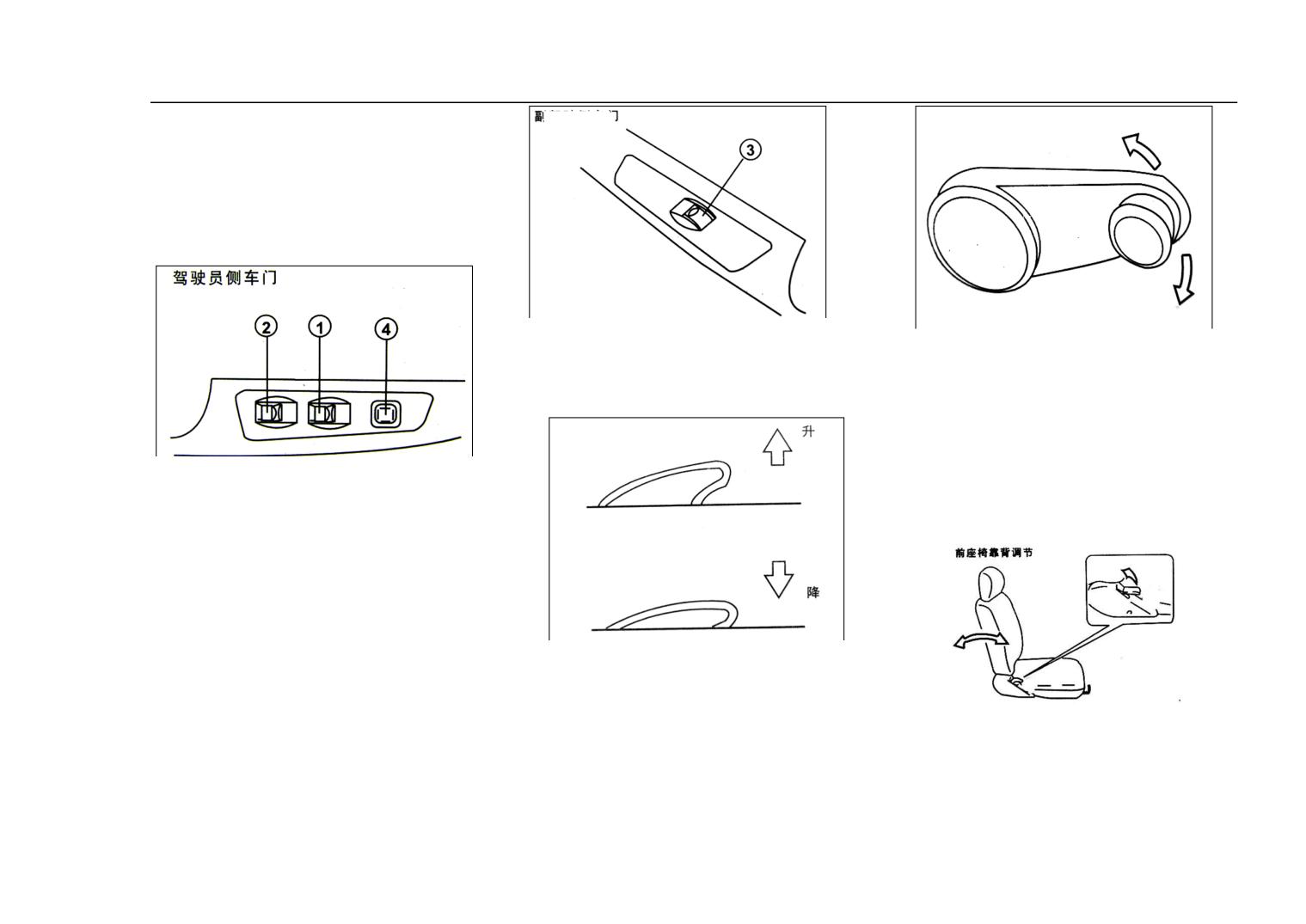
Press down the button 4, then button 3
The windows of rear doors are
can not work, press again, then the
controlled by the inner handle, the
button 3 is workable.
window will be close or open while
turn the handle clockwisedly or
There is a lift switch inside the door
counter-clockwaisedly.
while using the electric mechanism for
6. Seat
the window.
Switch 1 for the driver to control the
window in the side of the
co-pilot.
Pull up the button, the window will be
Switch 2 is for use of the window in
the driver’s side.
closed; press down the button, the
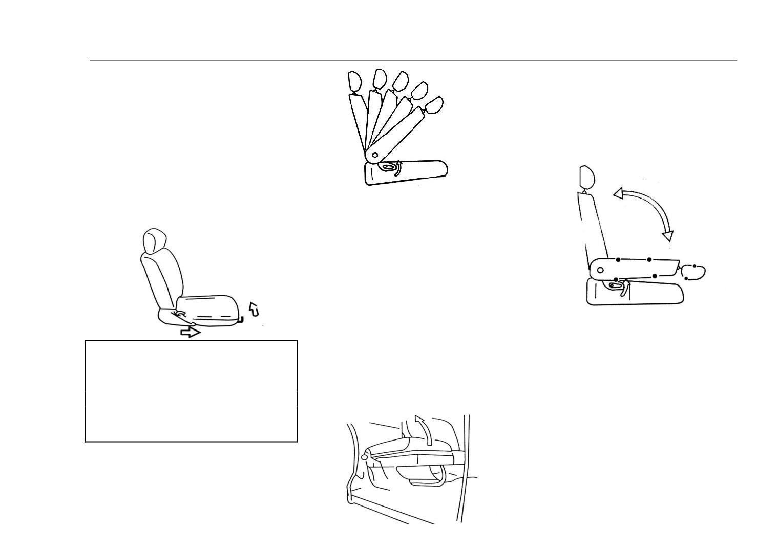
Front Row Seat
Switch 3 is for use of the window in
window will be open.
The fixing of the front row seat is
the co-pilot’s side.
5.
Rear Door window
just like the picture below, make the
11
Main Technical Parameter of the Complete Vehicle
two pothooks hook the button, and
then fasten it.
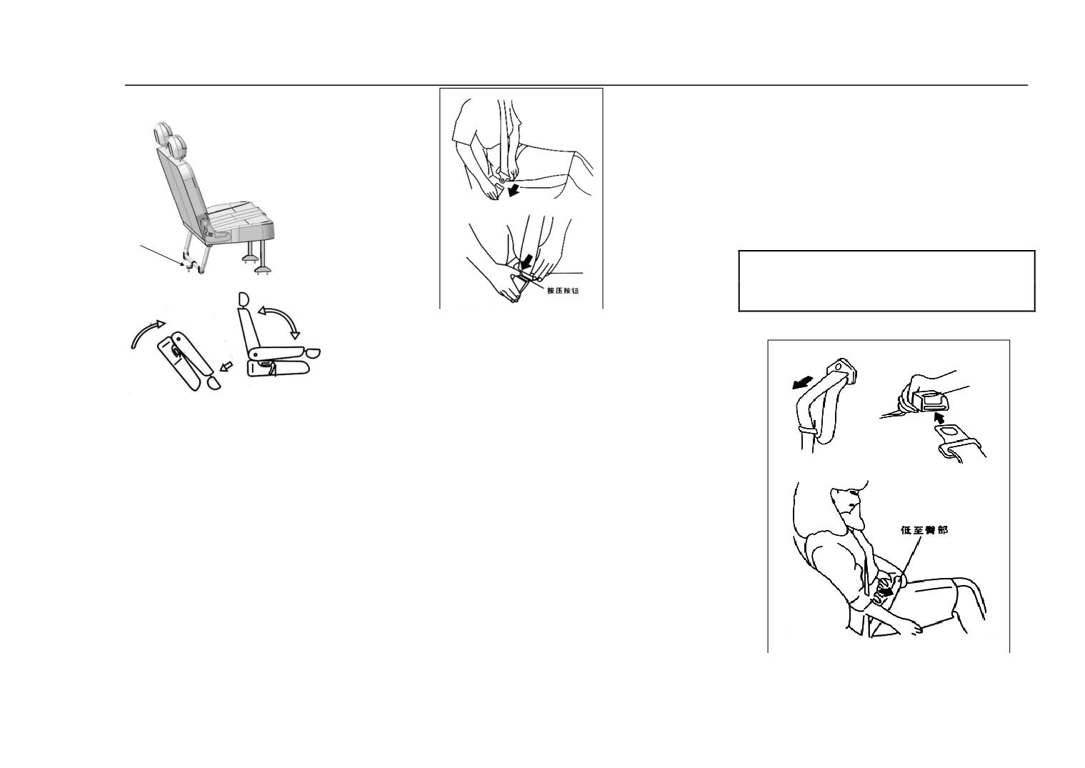
It is for three passengers, while folded the
Adjustment of the Front Row
extra one, pull outward the backrest locking
Seats:
device and fold the backrest horizonally,
Pull up the movable adjustable handle,
then pull forward the outward handle under
and the seat can be moved to a certain
the seat, fold the seat well and make it close
to the middle-row seat.
place as required; pull up the backrest
handle beside the seat, the backrest
can be moved freely, loose the hanlse,
the backrest will be locked and the
Middle-row seat:
backrest can also be folded forward.
The middle row seat has two kinds:
moveable and folding.
Movable Seat
Pull up the adjustor of the sliding rail,
and the seat can moved freely forward
or backward, while the seat moves to a
Rear Row Seat
Note::
suitable place, loose the adjustor, then
There is a stopper for the rear
No adjustment to the seat is
the seat will be locked.
allowed during the driving, or else, the
row seat, pull out the stopper, and
seat may move abruptly forward or
Folding Seat
backrest can be put horizonally, after
backward which may cause the
driving out of control.
than, loose the stopper handle; while
open, turn the backrest to the final
position, the stopped will be locked
12
Main Technical Parameter of the Complete Vehicle
requirements.While undo the safety
automatically.
belt; press the release button on the
lock catch.
The customers should not do any
amendments; otherwise it may cause
the safety belt not being adjusted
which will influence elasticity.
座椅锁闩
Note:
Pls wear the belt while driving.
7. Safety Belt
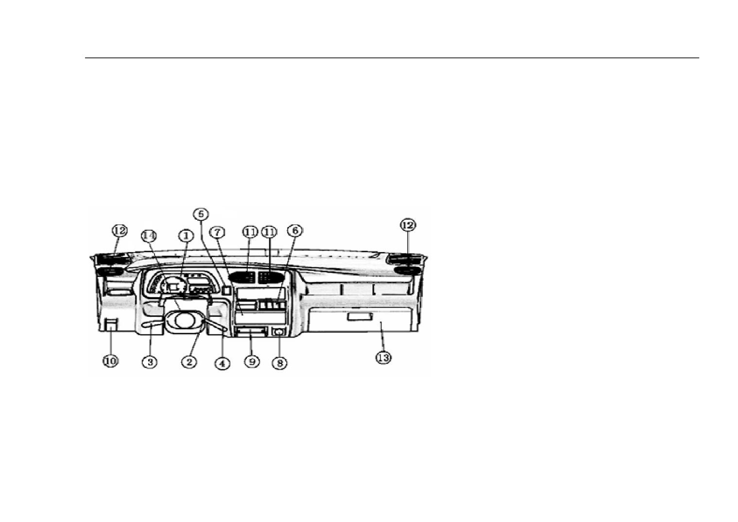
The safety belt of the front row seat is
automatic contraction.While using,
please pull out the lock tongue which
connect the safety belt and wing your
Turnover of the seat:
body and pass, then push the lock
There is a latch for the rear row
tongue to the lock catch until hear the
“clatter” sound.
seat, turn on the latch, the seat can be
The length adjustment of the saftety
turned over
90° forwardly so as to
belt is very important. While adjusting
As low as buttock
the lap belt, please check the lock at
loading or discharging goods. The
the meantime to make sure that it has
latch shall be guaranteed to be locked
been locked, and then pull up the
while the seat returns to its original
shoulder belt till the lap belt being
buckled tightly. The length of the
place.
safety belt can be adjusted freely
according
to
different
The safety belt is designed according
13
Main Technical Parameter of the Complete Vehicle
to the human body skeleton, (See the
Safety belt should be prevented from
Do not use the deformed saferty belt.
polishing compound, grease spot, chemical
picture). Please note that, the waise
One safety belt is only for one person,
article, especially storage battery sour liquid
band part shall not be across the
tie the children on knee of passenger
polluted. While washing, you can use
abdomen.
to the safety bealt is very dangerous.
neutral soap and water. If the safety belt is
The adjustment of the safety belt is not
The position of lock limit position
worn and torn, polluted or damaged, should
only reliable and comfortable but also
be changed.
should not interfere or block the safety
can help to make safer. Flexible safety
It is very important that when the safety belt
belt fully withdraw.
belt will influence its protection
impacted fiercely, though it is not obvious,
it should be changed.
function.
14
Main Technical Parameter of the Complete Vehicle
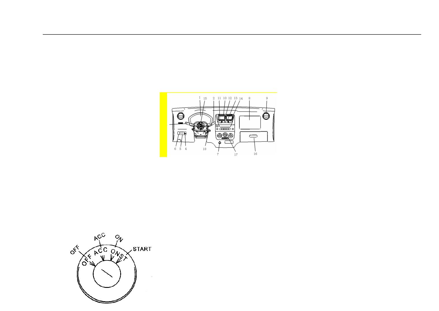
8. Dashboard
14 Emergency Switch
9、Side Intake
8. Dashboard(One and half of cabin)
①Assembled Meter
10、Centre Intake
②Ignition Switch
11、A/C Switch
③Lighting/Turning and high/low
12、Switch Assy Defroster
beam converting switch
13、Rear For Switch
④Wiper & Syringe Switch
14、Fog Switch
⑤Cover for Optional Switch
15、mergency Switch
⑥Other Switches
16、Tool Box
⑦Control Board for Heating
17、Control Board for Heating
⑧Cigar Lighter
1、Assembled Meter
18、Ignition Switch
⑨Cigarette Ash Box
2、Wiper & Syringe Switch
⑩Switch for front cover board.
3、Lighting/Turning and high/low beam
9. Fire Switch
11 Centre Intake
converting switch
1. ‘Off’: the auxiliary equipments don’t
12 Side Intake
4、Head lamp control switch
work, only head lamp and horn work,
13 Tool Box
5、Rear Foglam
and the key can be pull out only in this
position.
6、Rear Foglam
2. ‘ACC’: assisitant equipments
7、Cigarette Lighter
(radio & cigar lighter) work and the
engine don’t work.
8、Auxiliary Frame Air Bag
3. ‘On’: while at this position, all
15
Main Technical Parameter of the Complete Vehicle
the wiring can be put through and the
engine prepares to run.
4. ‘Start’: On this position, the
engine is started by the starter, once the
engine starts. Please loose the key
which will return to ‘on’automatically.
Do not keep the ignition key
in’ON’position for a long time unless
the engine is running, or else, the
battery will discharge.
Note: The working time for starter
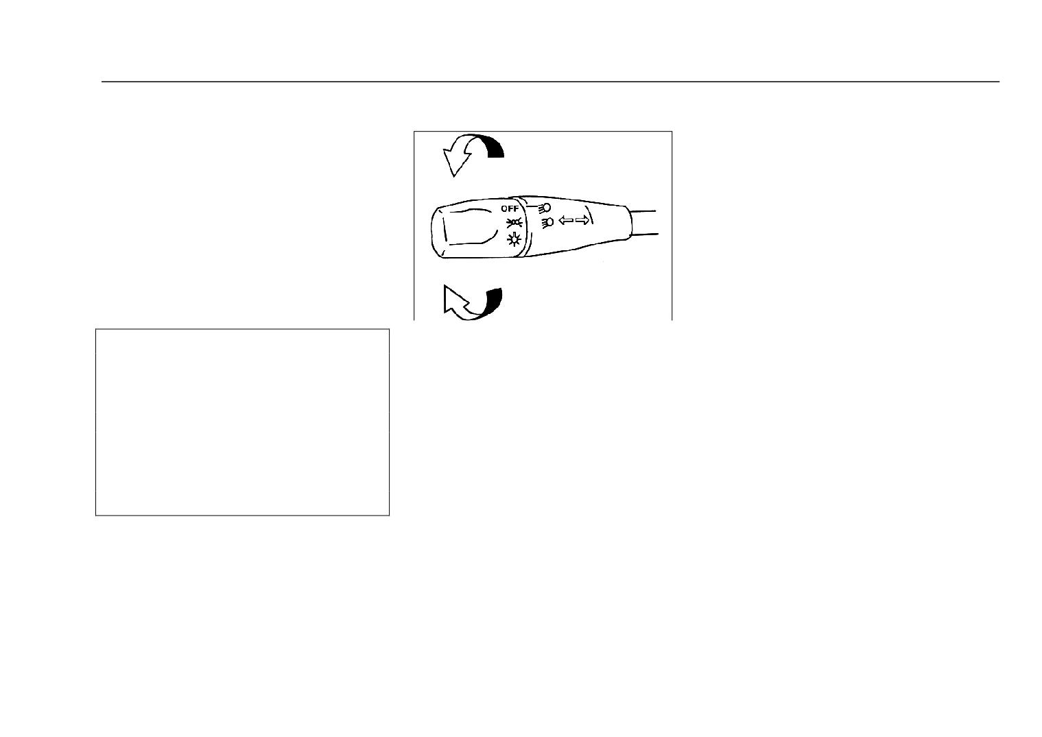
The control pole is in the left side
shall not exceed 5 seconds. If the
of the steering pole, the operation is as
engine cannot be started, please wait
at least five to ten seconds, and try
follows:
again. If the engine fail to start after
several times, please check the fuel
power supply system or pay a visit to
the Maintanence Stop of Dongfeng
Yuan Vehicle.
10.
Lighting, Turning and
High/Low Beam Control Pole
16
Main Technical Parameter of the Complete Vehicle
control pole be loosen, when there is no
lotion but turn on thecontrol pole will
lead damage to the generator. If
attempting to clean the dash by wiper
will lead damage to the wiper and glass.
The first step should be the wet of glass
then start the wiper.
Note:
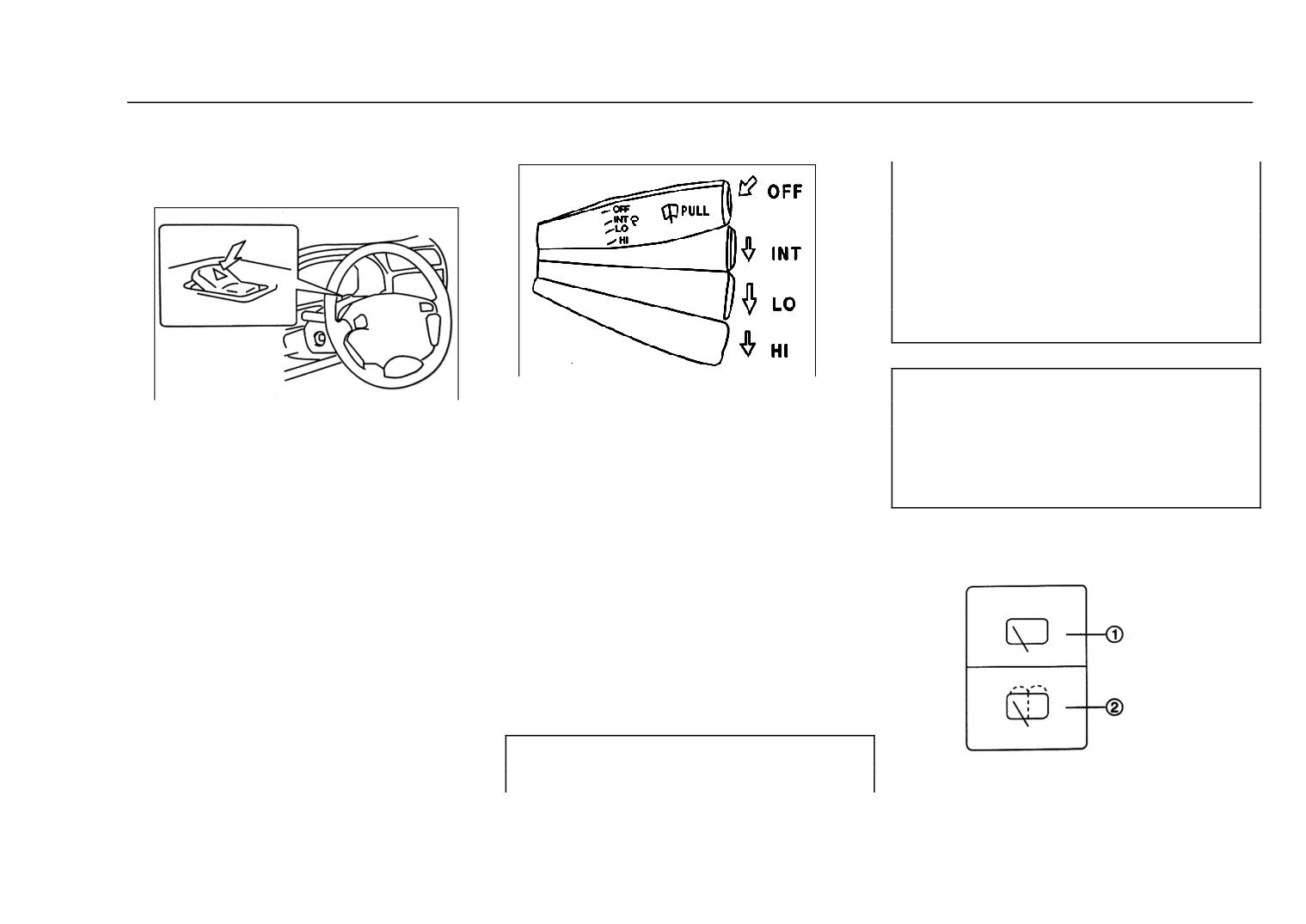
There are four gears
When it frozeon the glass should
Press down the button, all the four
the ice and snow be cleaned first and
INT:Intermission gear, whichis
turning lights and the side turning lights
connect to the defost device, then start
used when foggy and sprinkle
the wiper.
glitter simultaneously. Press the other
days.
end will turn off the lights.
12. Rear wind window wiper
LO:Run in a low but stable speed.
This switch is only used for emergency
and cleaner switch
situation and running in abnormal
HIGH:Run in a high but stable
situation.
speed.
11. wiper and cleaner control
OFF:Stop gear.
lever
Pull the control pole back
will lead to spray clean lotion.
Note:
When the lotion stops should the
Rear wind window
17
Main Technical Parameter of the Complete Vehicle
No cleaner and single-arm
wiper installed to rear wind
window.
Press the wiper switch (on
the dash board) one time, the rear
wind window wiper starts to
work.
Press the wiper switch
another time, the rear wind
window wiper stops.
13. Horn
The horn is going to roar
whenever the horn button is
pressed wherever the ignition
switch is.
18
Main Technical Parameter of the Complete Vehicle
Press down the button, all the four
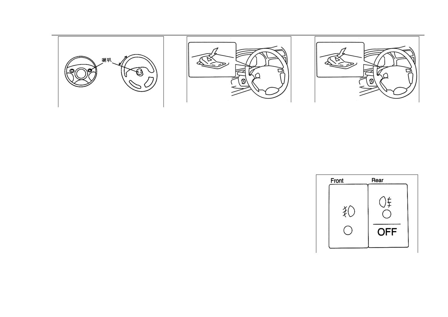
The horn button is on the wheel
turning lights and the side turning
Press the emergency light, all the
lights glitter simultaneously. Press the
panel
four turning lights and sideway
other end will turn off the lights.
① if it is a TOM’ style wheel
This switch is only used for
turning lights will flash at the
emergency situation and running in
panel, the wheel should be at the
same time. And press the other
abnormal situation.
middle of the panel.
side of the button will stop this.
15. Foglight Switch:
②if it is four-classified panel,
When the vehicle is in an
the horn should be at the both
emergency
or
abnormal
sides of straight range .
condition, use this switch.
14. Emergency light switch
Front Foglight:
Turn the headlight switch to the
19
Main Technical Parameter of the Complete Vehicle
the indicator light.
second gear, and press the foglight
Rear Foglight
switch, the foglight will be turned on,
Turn the headlight switch to the
and so will the indicator light; press
second gear, and press the foglight
switch, the foglight will be turned on,
again, the foglight is turned off, so is
and so will the indicator light; press
the indicator light.
again, the foglight is turned off, so is
16. Heating System:
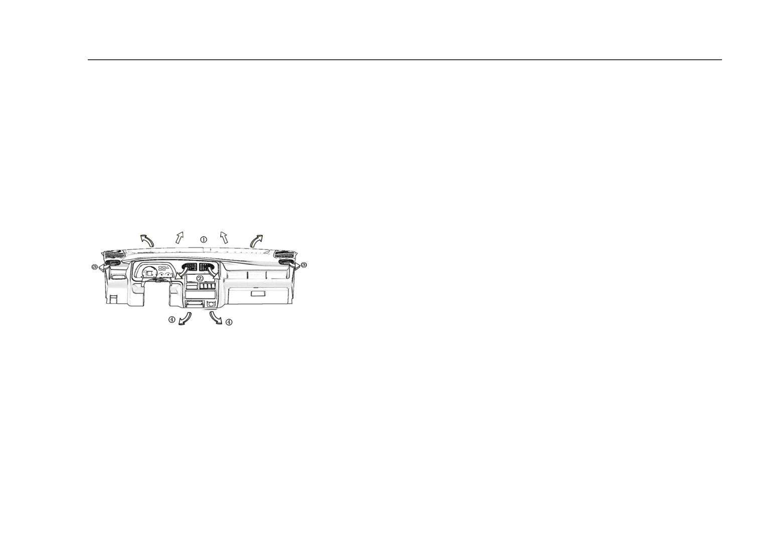
The heating system is for heating, defrosting and ventilation.
①Defrost Exhaust Valve of Windshield
②Centre Exhaust Port
③Side Defrost Exhaust Port
④Exhaust Port of the Floor
16. Heating System(One and half cabin)
20
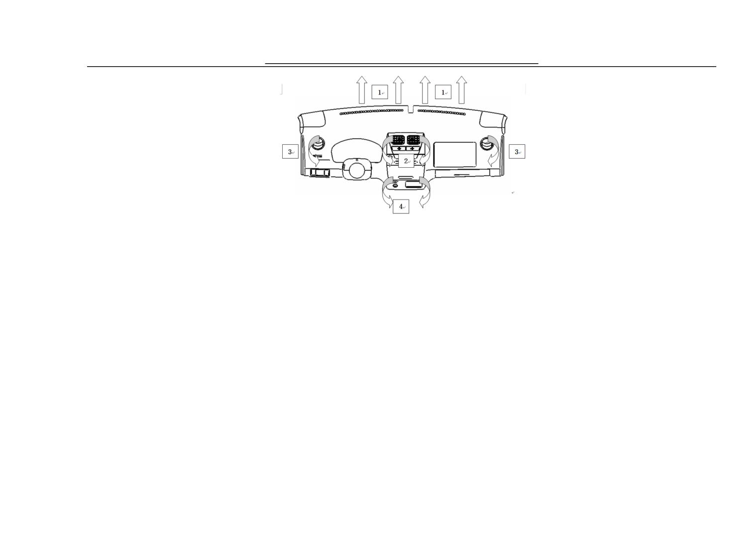
Vehicle Devicesxs and Mechanics Operation
①Windshield defrosting air door
②The central vent hole
③The side defrost vent hole
④The broad vent hole
21
Vehicle Devicesxs and Mechanics Operation
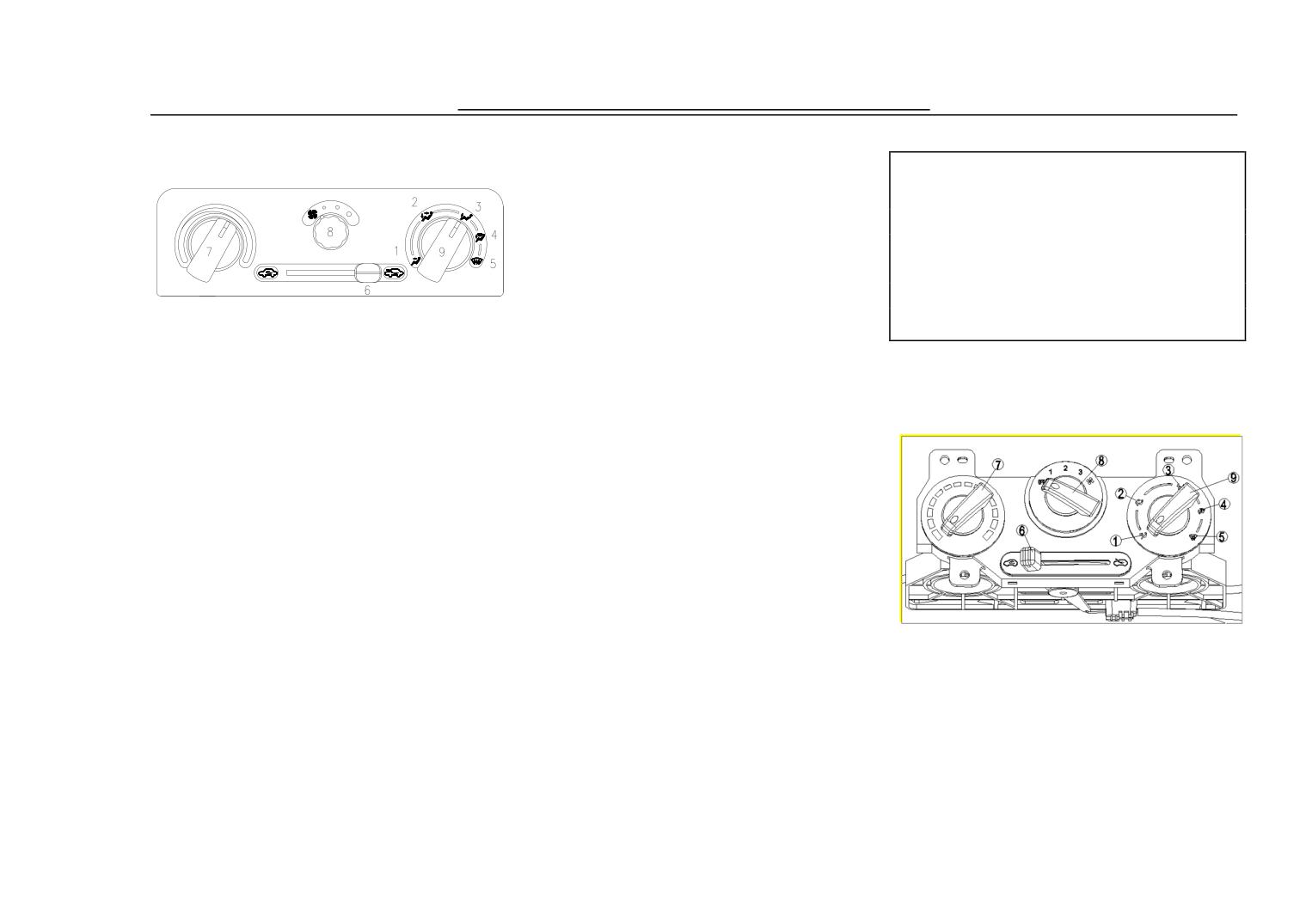
17.Control Board of Heating
the defrost exthaust port of windscreen
gas vent.
System
and side defrost exhaust port.
Note:
The time for blowing should not be
⑤ Defrost
too long while the air is in inner
⑥ Cycle Control Button of Inside
circulation so as to avoid the air in the
vehicle too dirty and the windpane
& Outside
will become humidity and with low
Control the circulation of the air of
thickness oxygen.
① The wind is sent off through
inside & outside.
17.
the intake in the centre of the the
⑦ Tempreture control button
Control Board of Heating
Control the tempreture of cold &
meter board or through side
System(one and half cabin)
warm air (blue is cold air, and red is
ventilation.
warm air)
② Sending off wind in both
⑧ Draft Control Button
directions: Cold air is sent off from the
Control the rotate speed of fan, that is,
centre intake, and the warm air is sent
adjust the draft.
off from the bottom intake.
⑨ Optional Button for Ventilate
③ Warm Air
Position
① The wind is sent off through
Warm air is sent off from the exhaust
This button can choose the warm air
the intake in the centre of the
port on the floor.
form from the aforesaid ①-⑤ gas
the meter board or through side
④ Defrost & Warm Air
vent. This button can choose the warm
ventilation.
Warm air is sent off from the exhaust
air form from the aforesaid ①-⑤
② Sending off Wind in both
port on the floor, some is sent off from
22
Vehicle Devicesxs and Mechanics Operation
Control the rotate speed of fan, that is ,
directions: Cold air is sent off from the
windscreen and side defrost exhaust
adjust the draft.
centre intake, and the warm air is sent
port.
⑨ Optional Button for
off from the bottom intake.
⑤ Defrost
Ventilate Position
③ Warm Air
⑥ Cycle Control Button of
Note:
Warm air is sent off from the
Inside & Outside
The time for blowing should not
be too long while the air is in inner
Control the circulation of the air of
exhaust port on the floor.
circulation so as to avoid the air in the
inside & outside.
④ Defrost & Warm Air
vehicle too dirty and the windpane
⑦ Tempreture control button
will become humidity and with low
Warm air is sent off from the
Control the tempreture of cold &
thickness oxygen.
warm air (blue is cold air, and red is
exhaust port on the floor, some is sent
warm air)
off from the defrost exthaust port of
⑧ Draft Control Button
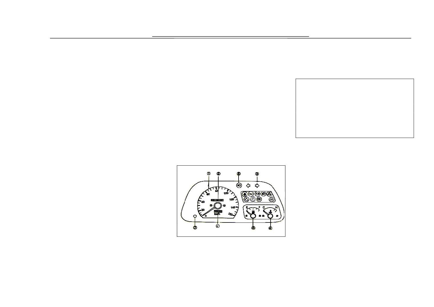
③ Left & Right turning indicator
light
④ Water Thermometer
⑤ Fuel Gauge
⑥ Short-range Odometer
⑦ Return Button for Short-Range
Odometer
This is just for reference
① Speedometer
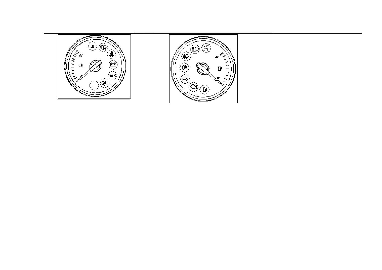
18. Assembled Meter
② Odometer
23
Vehicle Devicesxs and Mechanics Operation
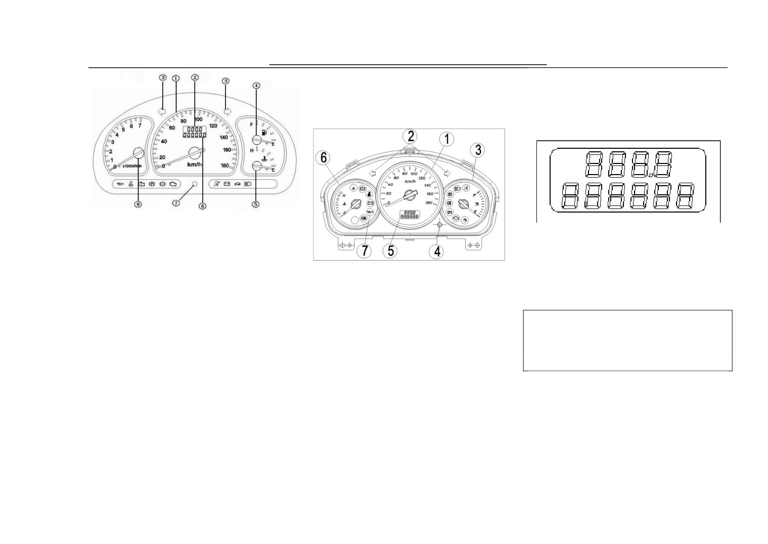
18.
Assembled Meter(One and half
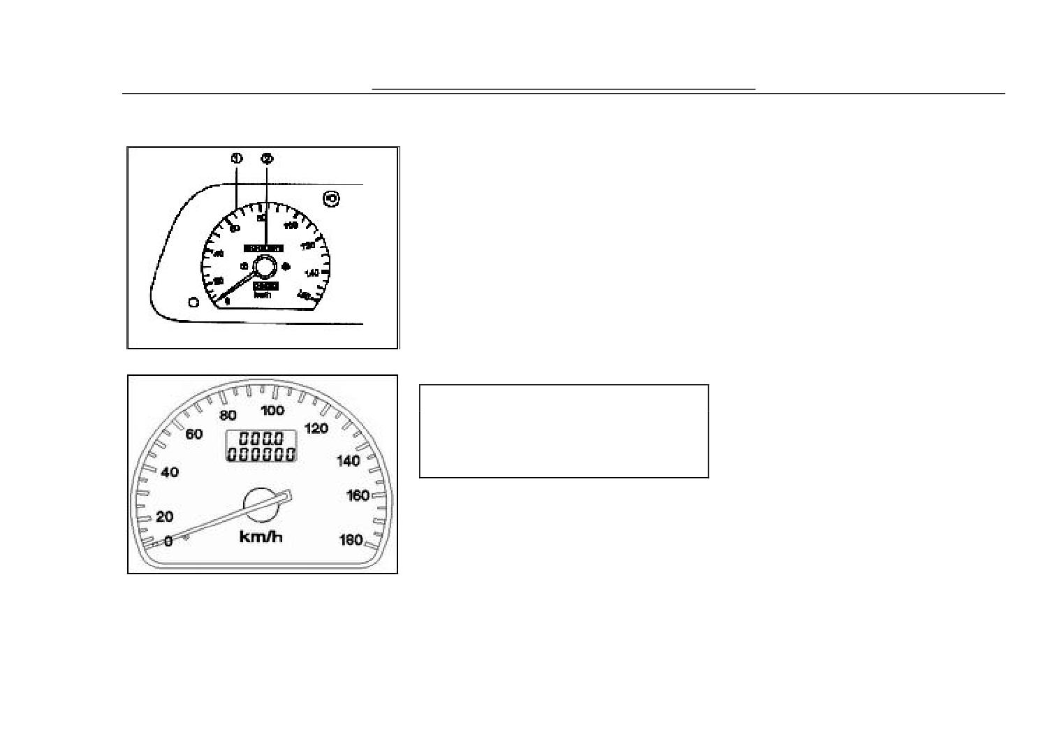
The speedometer expresses with km/h
the speed of the automobile.
cabin)
Odometer
The odometer has six -figure number
① Speedometer
in all to show the total driving mileage,
② Short-range Odometer
the minimum unit of mileage is 1km.
The picture is just for reference)
③ Left & Right turning indicator
Odometer after finishing caculation ,
light
① Speedometer
count again since " 0 " , analogize
sequentially to count for the first time.
④ Fuel Gauge
② Left & Right turning indicator
Note:
⑤ Water Thermometer
light
Pay attention to the running
⑥ Accumulative total odometer
mileage, and maintain the vehicle
③ Fuel Gauge
⑦ Return Button for Short-Range
according to this instruction manual..
Odometer
④ Return Button for Odomet
⑧ Tachometer
⑤ indicating instrument
Water Thermometer
⑥ Water Thermometer
⑦ Function Indicator Light
Speedometer
24
Vehicle Devicesxs and Mechanics Operation
While driving, the water
While the pointer at the
tempreture should be kept in the
‘F’position, it shows that the fuel tank
normal scope, that is: between ‘C’&
is full of fuel; while at the position of
‘H’. When the pointer moves to
‘E’, it shows the fuel tank is empty
‘H’direction and exceeds the scope, it
means the engine too hot, you should
stop the vehicle.
Fuel Gauge
25
Vehicle Devicesxs and Mechanics Operation
in all to show the total driving mileage,
18.
the minimum unit of mileage is 1km.
Assembled Meter
Odometer after finishing caculation ,
count again since " 0 " , analogize
sequentially to count for the first time.
The short odometer has four figures to
show the speed.
18. Assembled Meter
In the short range of milage, the last
figure means the figure behind the
decimal, the minimum unit of mileage
is 0. 1km, the return button can return
the mileage of short distance of
图 1
odometer to " 0 " mileage.
Note:
Pay attention to the running mileage,
and maintain the vehicle according to
this instruction manual.
图 2
The speedometer expresses with km/h
the speed of the automobile.
The odometer has six -figure number
26
Vehicle Devicesxs and Mechanics Operation
18. Assembled Meter
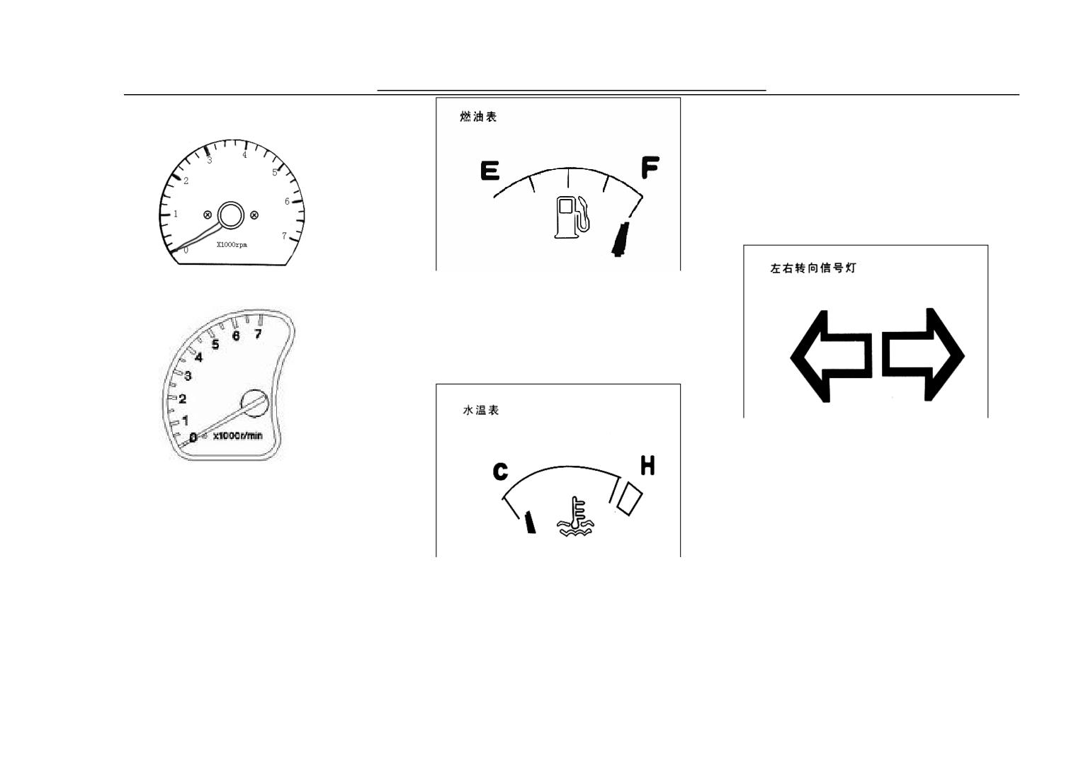
‘H’. When the pointer moves to
‘H’direction and exceeds the scope, it
means the engine too hot, you should
stop the vehicle.
18. Assembled Meter
While the pointer at the ‘F’position, it
Chart 1
shows that the fuel tank is full of fuel;
while at the position of ‘E’, it shows
the fuel tank is empty.
18. Assembled Meter
When the ignition switch is on the
position of turn-on, making the
Chart 2
turning switch gets through, the
indicator light will flicker and the
Tachometer
turning light turns on showing turning
Show the rev of engine with
signal given. Turning left, the left
indicator light turns on; turning right,
1 unit as 1000rpm.
While driving, the water
the right indicator light turns on.
18. Assembled Meter
tempreture should be kept in the
18. Assembled Meter
normal scope, that is: between ‘C’&
27
Vehicle Devicesxs and Mechanics Operation
18. Assembled Meter
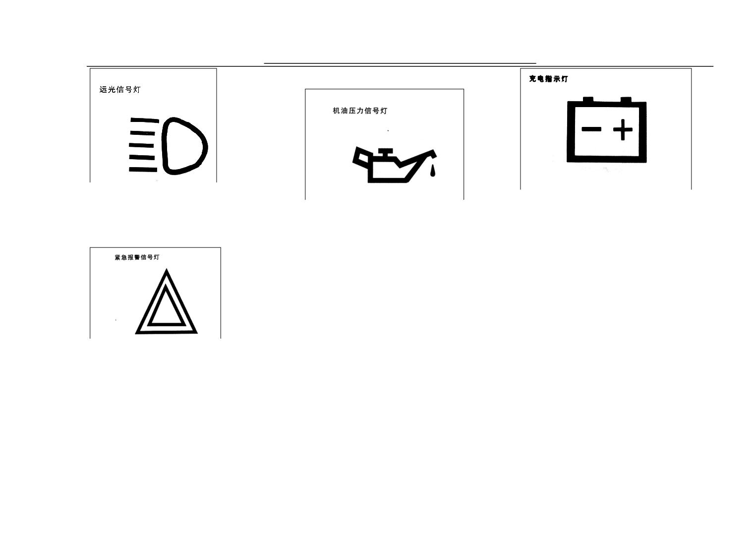
When every headlight adopts high
When ignition switch puts through,
beam or dipped headlight, this
When putting ignition switch through,
this indicator lamp lights immediately,
indicator light will be on.
this indicator lamp lights immediately,
and engine goes out immediately after
18. Assembled Meter
after the engine is started, it will go
starting. Otherwise it shows the
out immediately. Otherwise it shows
battery charge system breaking down,
the oil level of the bottom shell of the
please check if the fan belt ruptures or
engine passes low or the lubricating
relaxes at first, if normal, carry on
system breaks down, please make the
circuit check again or get in
engine go out and carry on the oil
touch.with the distributor or Dongfeng
level check and annotate immediately.
YUAN Maintenance Department.
If fail to fix a breakdown yet, please
While confronting emergency, please
go on an all-round way checking of
lubricating system or get in touch.with
use the emergency light, the indicator
the local distributors or Dongfeng
light flickers so as to avoid hitting the
YUAN Maintenance Department.
behind vehicles.
18. Assembled Meter
Note:
This switch can be only used
when meeting emergency.
28
Vehicle Devicesxs and Mechanics Operation
18. Assembled Meter
Note
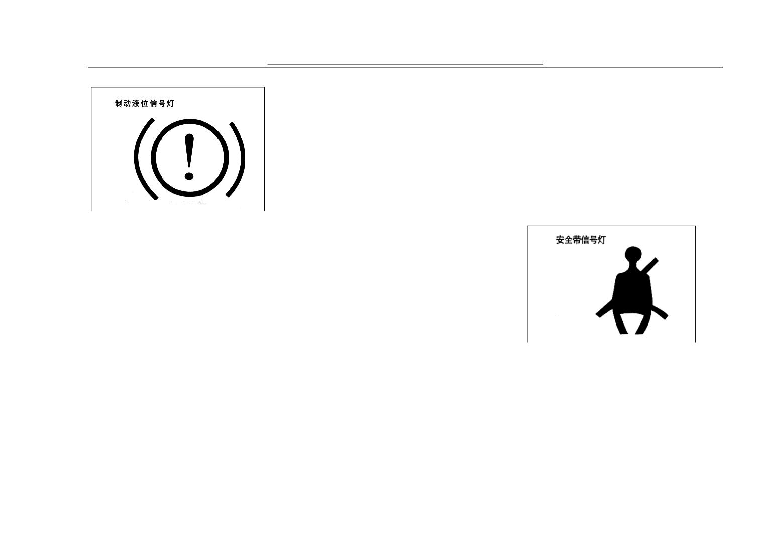
It shows the brake system
Note:
breaks down when the ignition
At this situation,
it
switch is on the position of
necessary to need longer
‘ON’or ‘START’ but the
parking distance, more powerful
indicator light is not on or it is
pedal force and longer pedal
not out after the engine starts or
stroke.
the indicator puts through
abnormally while driving. If on
these cases, please ask the
In normal cases, when the ignition
Dongfeng YUAN Maintenance
Department for help.
switch in
‘ON’ or " START "
When the indicator light puts through
position, the light is on , and it will go
abnormally, please bear the vehicle off
out after the engine starts.when the
the road and test the brake system on
liquid level of the container of brake
the roadside.
liquid is lower than the fixed liquid
After test, please drive the vehicle to
the nearest maintenance stop at low
level, the light will be on. And it will
When the ignition switch puts through,
speed if you believe it is safe for do so.
this indicator light will be on and will
be out after adding brake liquid
Otherwise please trailer it to the
be out after the safety button inserting
maintenance stop.
according to the regulation.
into the safety belt fixing housing
18. Assembled Meter
which shows the safety belt has been
well buttoned.
18. Assembled Meter
29
Vehicle Devicesxs and Mechanics Operation
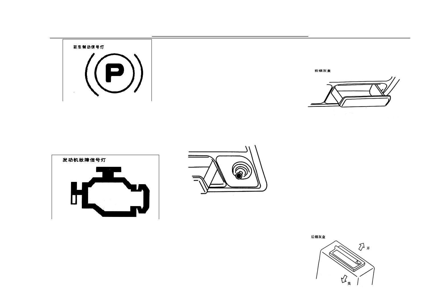
indicator lamp will go out, if the
position.
trouble indicator lamp does not go out
20. Cigarette Ash Box
while the vehicle starts or lights in the
course of running, it shows the engine
control module breaks down , please
While the ignition switch is in the
ask Dongfeng YUAN Maintainer for
position of put-through and the
help.
parking brake is in the condition of
The ash box can be used after being
19. Cigar Lighter
unreleased, the parking brake light
pulled out, while clearing up the
will be on.
cigarette ash, push it downwards, then
totally pull out from the socket
18. Assembled Meter
outwards. Push the ash box along the
guide while putting.
Note:
The cigarette end should be
put into the ash box after
putting it out so as not to
cause fire.
Press the cigarette lighter button, wait
When the ignition switch is in the
20. Cigarette Ash Box
several seconds and the resistance
position of ‘ON’, the trouble lamp will
be on, it shows the the trouble lamp
wire will turn red and hot, and it can
circuit is normal.
be taken out to use after it
After the engine is started, the trouble
automatically rebounds to its original
30
Vehicle Devicesxs and Mechanics Operation
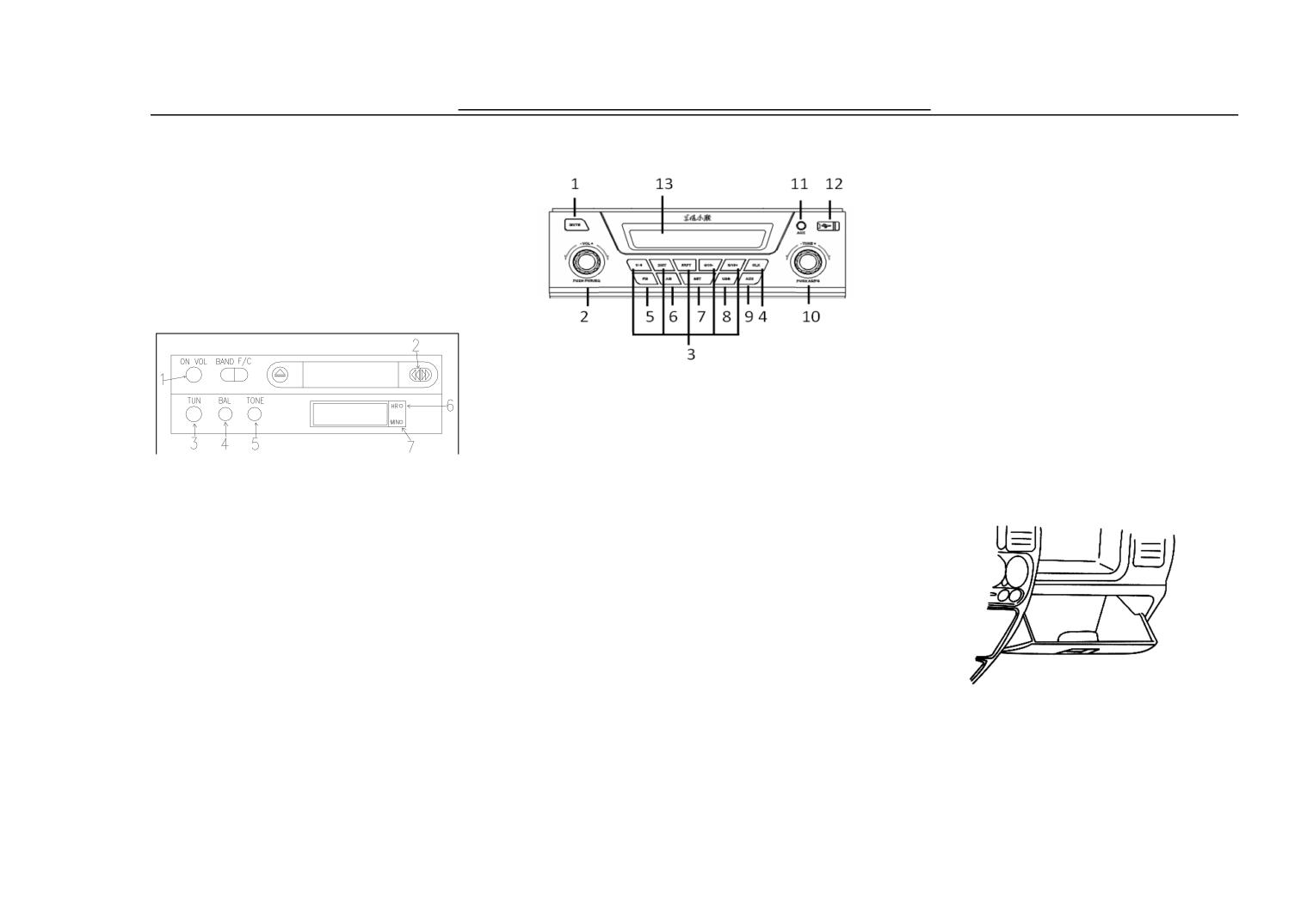
(12)USB
Put the cigarette end into the ash box
after going out. While clearing up,
press the ash box spring down, you
22. Tool Box
can pull out the box. Hold the ash box
1. Electric Source Switch & Volume
vertically and insert it to the groove
until clenching the teeth of the trough.
2. Advance/Back Key
21. Stereo Radio
3. Wave Band Tuning Knob
4. Balance Control Knob
(The picture is just for reference)
5. Tone Control Button
(1)MUTE
6. Hour Setting Key
(2)On-Off/ Sound Effect Knob
(The picture is just for reference)
7. Minute Setting Key
1 Electric Source Switch & Volume
( 3 ) umber Button
22. Tool Box
2 Forward/Back Key
(4) Lock Set Button
3 Wave Band Tuning Knobs
( 5 ) FM Button
4 Balance Control Knobs
( 6 ) AM Button
5 Tune Control Button
(7)SET Button
6 Hour Setting Key
( 8 ) USB Button
7 Minute Setting Key
(9)AUX Button
23. Inner Light & Interior
Rear View Mirror
21. MP3& Radio(One and
(10)AS/PS Knob
half of cabin)
(11)AUX
31
Vehicle Devicesxs and Mechanics Operation
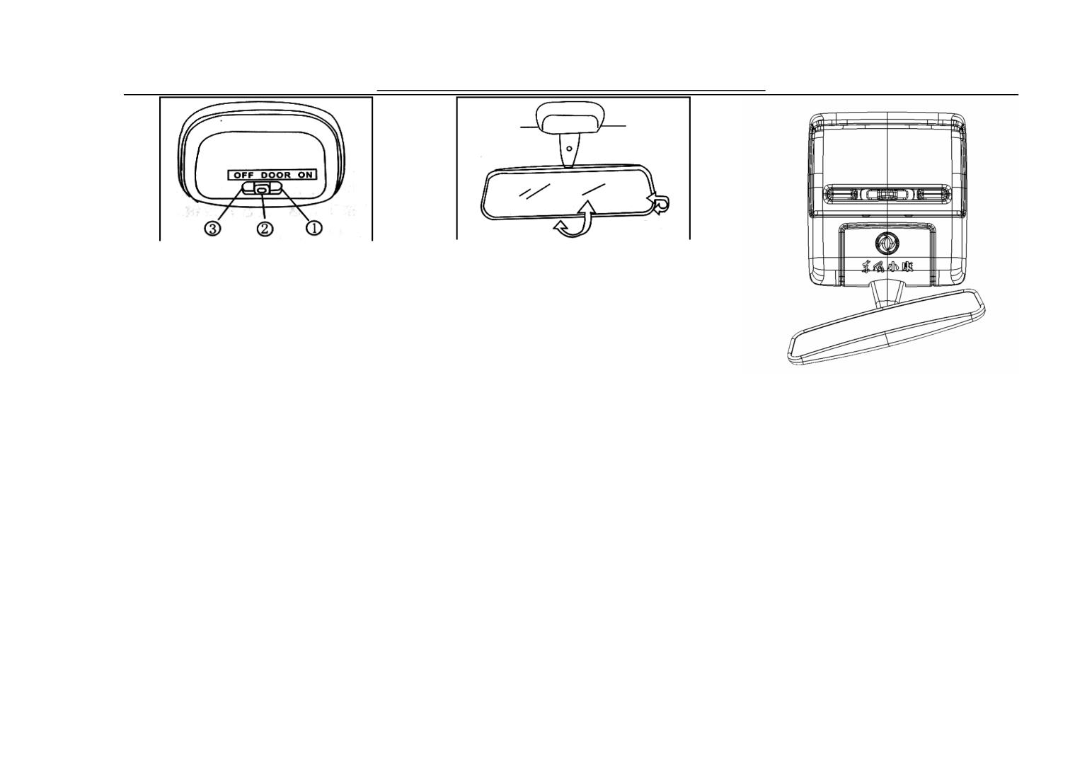
The indoor light button consists of
Regard the inner mirror and inner rear
three pieces of shelf location.
view mirror as a combination and it is
“OFF" is closed.
set up in the middle of the top of wind
“DOOR “means switch at the door,
window.
When the button is in this shelf, the
Inner view mirror can rotate from side
light is off while closing the door and
to side up and down along central axle;
the light is on while opening the door.
and park it at the any position inside.
The indoor light button consists of
As any door is closed uncompletely,
23. Inner Light & Interior
three pieces of shelf location.
this light will not go out.
Rear View Mirror
“OFF" is closed.
“ON” means being turned on, while
the button is at this shelf, the inside
“DOOR “means switch at the door,
light will be on.
when the button is in this shelf, the
23. Inner Light & Interior
light is not on while closing the door,
Rear View Mirror
and the light is on while opening the
door. As any door is closed
uncompletely, this light will not go
out.
“ON” means being turned on, while at
this shelf, the inside light will be on.
32
Vehicle Devicesxs and Mechanics Operation
that you can see the behind vehicles or
24. Interior Top Lamp
other objects through it. And the
Safe handgrip is located on the upper side
surface of the outer rear-view mirror is
of each seat (The driver’s side doesn’t
protruding surface.
have.)
While judging by the vehicle or other
objects through the protruding lens,
Note:
please pay attention that the articles will
While in the course of running, the
be much smaller and farther than seeing
passenger should hold the handgrip
through the flat mirror.
tightly.
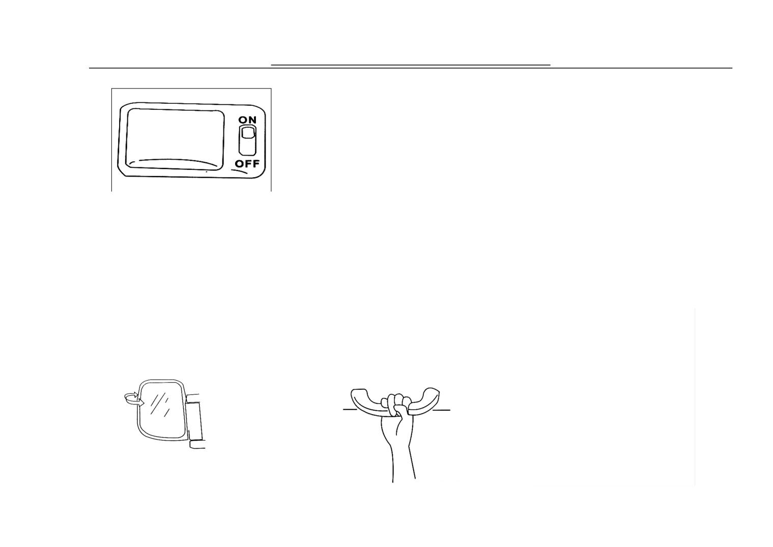
The interior top lamp is set between
26. Sunshading Board
Do not hang anything on the handgrip
the top of middle row and rear row of
The sunshading board can rotate up
to prevent it from influencing the
seats, with two shift position.
and down by winding its pivot. While
driver’s line of sight which may cause
adjusting, place hands close to both
accident.
ON means open; Put thebutton in the
ends of the mount ing pad and rotate.
position, the lamp is on.
28. Tool Kit
OFF means close, put the buton in the
There is a small mirror on the back of
sunshading board which is on one side
position, the lamp is off.
of co-pilot.
25.
Outside Rear View
27. Safe Handgrip
Mirror
Adjust the outer rear-view mirror
according to your demands making
33
Vehicle Devicesxs and Mechanics Operation
① Tool Bag
② Plier
③ Hatch Spanner12×14
4 Screwdriver
5 Handlebar of Screwdriver
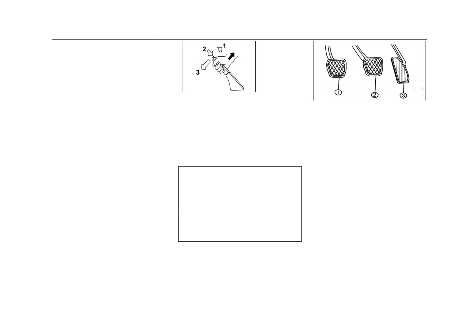
Draw up the brake rod, the vehicle
Clutch Pedal
6 Handlebar of Sleeve
will stop; when release the stopping
Clutch pedal can break transmission of
7 Sleeve for Spark Plug
brake, pull the brake rod a little up and
engine and wheel. Step down the
8 Spanner for Tyre
footboard,
the
engine
power
push the button on the top of the brake
9 Crank of Jack
disconnects, loose footboard, power
10 Jack
rod with thumb and then put back the
recover.
11 Triangle Warning Plate
brake rod in the normal position.
The tools shown in the picture are one
Note:
for
each,
and
Parking brake rod should be drawn up
②③④⑤⑥⑦⑧⑨⑩ should be
totally, otherwise it is unable to
put in tool bag ①. Please refer to
prevent wheel from rotating, when
Brake Pedal:
Chapter 5 ‘Instruction for using Jack’
parking in the extremely cold weather,
to check the placement of the jack and
al condition such as cold, humidity,
please put the shelf in the low-grade or
jack crank.
ice and snow etc. will cause the brake
reverse grade, live in the wheel with
shriek, it is normal, if the brake
cushion headblock.
screams in every brake or shrieks
29. Brake Rod by hand
loudly, please check the brake system.
30. Pedal
Accelerator Pedal:
The rotating speed is controlled by
accelerator pedal, step down the
34
Vehicle Devicesxs and Mechanics Operation
accelerator pedal, the rotating speed of
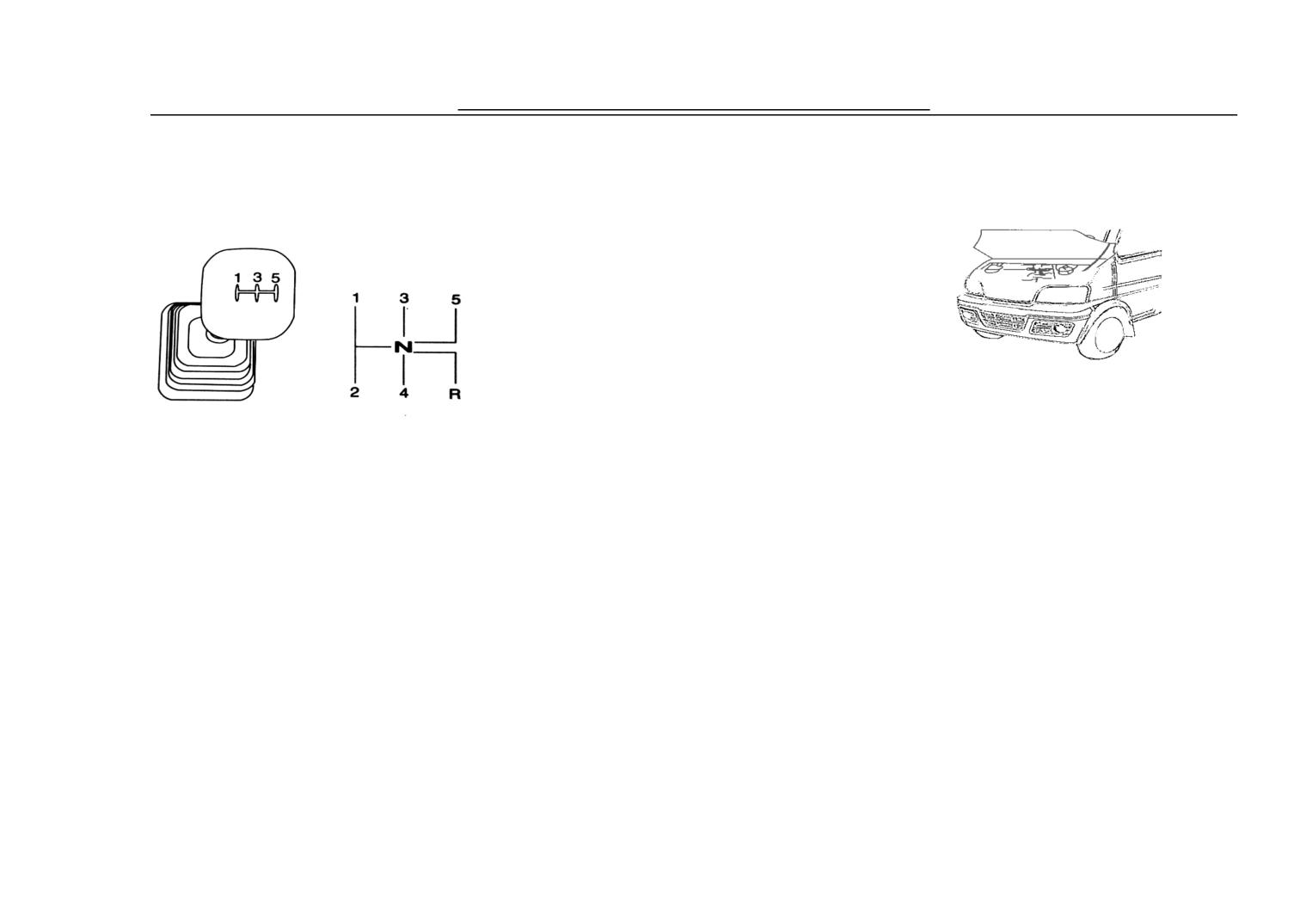
Reverse gear: pull towards left
the engine will increase and the output
32. Front Storehouse Cover
power will go up.
31. Shift Handlebar
1st gear: first pull towards to left and
T
lies
then push forward.
b
of
2nd gear: first pull towards to left and
th
ng,
then pull backward
pl
and
3rd gear: push forwards in the central
th
ont
position
cover, then prop up storehouse cover
4th gear: push backwards in the central
with struts.
Note:
position
Do not change the gearlever
5th gear: pull towards right first and
from 5th gear into reverse gear.
then push backward
Please first push the gearlever to
neutral and then change into
reverse gear.
35
Vehicle Devicesxs and Mechanics Operation
Ⅳ、Operation of the Vehicle
36
Vehicle Devicesxs and Mechanics Operation
The first
1.Running-in
Gear
2500
In the course of car running-in, we use
Note:
kilometers
the best material, every part is
Once the engine starts, please
processed meticulously, but before
the
Max
Gear 1
15Km/h
release the ignition key to disconnect
letting the engine bear peak load, each
Recommended
Gear 2
25Km/h
the starter, otherwise, it may cause the
operating should pass running-in stage.
Speed
starting system to be damaged. Do not
Gear 3
40Km/h
The
initial
maintenance
and
try to sart the engine once for more
running-in of the engine have close
Gear 4
60Km/h
than five seconds, if it fails to start,
relationship
with
its
future
Gear 5
75Km/h
please try again ten seconds later (let
performance and dependability quality,
the battery supplement electricity).
2. Start of the Engine
the general principle that should be
After the cold engine is started, don't
followed is as follows:
Before the Start of Engine
make the engine run idle at a high
1. The running-in mileage is 2500KM.
Make sure the brake has been
speed.
2. Do not exceed the running-in speed
locked up.
3. Safety Driving
limit value listed in the table below.
Make sure the joy stick of the derailler
Start the Engine
3. While in the course of running-in,
is in the position of neutral.
the loading born shall be lessen than
①While turning the ignition switch
400kg.
to “START ", you can start the engine.
4. After starting, do not make the
Note:
The electric jet system can offer
engine run idle at high speed, please
Before starting the engine, hold
suitable blending gas mixed by oil and
pre-heating the engine.
the hand brake to lock up the
gas and ignition advance angle, so it is
wheel and the gearlever should be
unnecessary to step on the throttle
in the position of neutral.
37
Guide for Vehicle Operation
under any circumstance..
after starting, the curb idling will be
parking at the slope which may
②If you can't start engine while
normal, and then repeat the above
damage the clutch.
trying several times, the engine might
While driving the vehicle, drivers
course.
Please check at first
should frequently observe the
happen with “flood the jar “which
whether there are vehicles coming
instrument and indicator lamp, and do
cause the short circuit of the spark
not step on the gas before the engine
here and then step on the clutch to
do not reach normal working
plug. On this situation, please
have a try, then put into the low-gear,
temperature (80 degrees Centigrade -
completely step down the throttle
90 degrees Centigrade), otherwise will
if it is difficult, please step on the
pedal and try again to start the engine
shorten the life-span of the engine and
clutch to try again, after putting to
hinder changing the gear steadily. The
(then the ECU will control fuel
drive is along with synchronization
gear, let go of brake pole, meanwhile,
injector cutting off oil supply). Five
test machine which make the gearshift
easy and without noise. A good
step on throttle slowly, when step on
seconds later, the high-speed air
gearshift would enable rotational
the clutch, listen to the voice of the
current blow down the overflow oil
speed of the engine remain throughout
in a certain range, and no matter how
and then let go of gas pedal and can
engine, with the gradual release of the
the speed change, you can both save
restart the engine at this moment.
clutch, the engine voice will
the fuel and lengthen the life-span.
③If ECU has been cut out (such as
change,then step on throttle and let go
4. Brake
The braking distance of the vehicle
change the battery, ECU, and ECU
of clutch pedal gradually.
increases with that of the speed of
will not power off while parking),
3. Safety Driving
vehicle, while applying the brake, you
should guarantee that there is enough
when starting, please turn the key to "
When driving the vehicle, don't
distance for the vehicle to get to the
regard the footboard as a stop for a
brake parking point in order to
ON ", if failed, please wait for five to
decelerate gradually.
rest, or don't half step on clutch while
ten seconds or wait fifteen seconds
Step on down brake pedal, the front
38
Guide for Vehicle Operation
and rear brake will work at the same
lower the fuel consumption:
time. If there are shrieks some times
①Avoid running idle for a long time:
while braking, it is because of
humidity of the road surface or cold
If you don’t drive the vehicle after
and snow weather etc. So it is a
waiting more than one minute, you
normal.
should stop running the engine. While
starting the cold engine, you should
operate idly until the indicator of the
Note:
thermometer reaches “C " position ,
If there are always shrieks when
then begin to drive a vehicle.
brakes, please go to the Service
The vehicle is equipped with vacuum
②Avoid Emergency Brake: it is a
Station of Dongfeng YUAN.
helping system; it can make the brake
Don't apply the brake in succession
waste of energy for braking and also
more stable. Do not step on the brake
for a long time, or put the foot on
pedal to-and-fro while applying the
recovering driving speed will consume
the brake pedal while running for a
brake. When the vacuum helping
rest which will cause the brake to
the fuel.
system lose efficiency, the energy
lose efficiency for overheating or
stored will gradually subside effort in
③Keep the invariable speed: Keep
the braking distance too long or
brake pedal with applying the brake
will cause the permanent damage
the invariable speed in the allowed
each time.
of the brake.
road and traffic condition.
Note:
5W
ithout the vacuum helping system,
④Keep the loading capacity
Note:
Eit will need more footboard stren
gth
minimum limi
After water enters the brake drum, it
e brake and
Ewhilemapplyinginth
will make the brake lose efficiency or
perhaps the braking distance will be
⑤Keep the correct tire pressure:
its performance cannot be predicable.
The following items will help you to
longer.
when the tire pressure is insufficiency,
So after the vehicle paddles or being
washed, you should lightly step on the
39
brake pedal intermissively at a much
low speed, operate the brake
repeatedly, and dehumidify brake until
Guide for Vehicle Operation
Driving on the icy road
low gear promptly according to the
the resistance for driving will increase
You can use the tire tyre chain in
slope and the rotational speed of
which may cause the waste of the fuel,
order to prevent the tire sliding on the
engine in case that the engine
icy road.
overloads or being damaged. Pay
then the tire should be pumped
Step on the brake pedal repeatedly and
attention to following points while
according to the pressure indicated on
steadily and evenly while applying the
driving on the ramp:
the plate of the the driver’s side door.
brake, instead of stepping on the brake
①The vehicle should be changed into
pedal suddenly so as to achieve ABS.
low gear while climbing the slope in
Start, accelerate or when driving a
vehicle, please keep invariable speed
order to increase the engine torsion.
to prevent wheel from turning round
Gearshift should be fast in case that
Note:
and round or skidding which may
the engine stops working;
Please don't slide with neutral
cause the vehicle sideslip.
when going, because vehicles with
① Vehicle should be put into
Avoid the operation of the steering
electric jet system have the function of
wheelby turning fast or at large angle.
low-gear at the downhill path, try to
gearing down and cutting off oil
Decrease to the safe speed and slowly
supply which can guarantee the
brake the vehicle by taking advantage
change direction.
economy driving. And the engine
If increasing the friction by equipping
of engine.
keeps working at idle speed while
with tyre chain, please pay attention to
② Try not to make the rotational
running with neutral; it will still
following points:
consume the fuel instead of saving
Assemble the vehicle according to the
speed very high.
fuel.
Instruction
Manual
of
the
manufacturer.
Note:
The speed should be limited below
Do not step down the brake
50KM/H while driving with tyre
pedal for too long time or step the
chain.
brake pedal for many times while in
5.
Economy Driving &
Driving on the ramp (road of
the course of abrupt slope long
mountain area)
slope, which will cause the brake to
Environmental Adaptability
While climbing, change the gear to a
lose its braking ability for being
overheated.
40
Guide for Vehicle Operation
41
Guide for Vehicle Operation
Ⅴ. Guide for Vehicle Operation
42
Guide for Vehicle Operation
damaged, and method of adjusting and
1.Fuel
about 6-9mm and assure there is no
changing of the belt are as follows:
any damage to the belt. If the belt
1. Unclamp the three setscrews of the
generator.
needs replacement or adjustment, pls
2. While wanting to stretch the strap,
go to the authorized service center of
unscrew and draw outwards the
generator, fix the generator when the
DFM mini auto for maintenance.
strength
of the
belt
reaches
4. Engine Oil
above-mentioned criterion.
Engine Oil Trademark
3. While changing the strap, unscrew
The oil shall be No. 93 high-quality
Use 15W/40SP while the tempreture is
and make the generator slip and move
unleaded gas. The capacity of fuel
above
15°in summer; and use
inwards, Tighten the strap according
tank of this vehicle is 40 liters; Refuel
10W/30SF (GB11121) while the
to the regulation of 2 after changing
access cap lies in the right below part
tempreture is below 15°in winter.
the strap.
of center pillar. Open up the the cover
3. Compressor Belt
by key and turn counterclockwise, and
Note:
then turn the key clockwise to cover it
MeasChange the engine oil while the,
tightly.
erunning-inoof lthel new gasoline
2. Generator Strap
svehicler isit2500KMityandteafter
enormal driving for 5000KM.ne use
and maintain the manual.
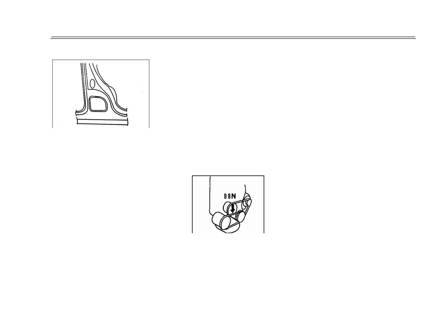
While exerting the strength of about
98 Newton (strength of 10 kilograms)
to the adhesive tape of the fan between
4. Engine Oil
The vehicle with A/C is
the generator and fan, the down
quantity of new fan adhesive tape is
equipped with compressor. During
about 7-10 mm and the down quantity
inspection, press the belt by the thumb
of old fan adhesive tape is 10-15mm.
In addition, check whether the belt is
with the regulated power, it will sink
43
Check/Maintenance Service
petrol machine use and maintain the
manual.
5. Engine Belt
7. Thermostat
Note:
Note:
In order to make oil filter fasten
It
is
dangerous to
properlr, the more important thing
discharge the radiator cover
is to mark the position while the
while the temperature of the
small filter rubber washer meets
water is very high, because the
the installing surface and the oil
boiled water and steam will be
filter should not be screwed too
Replacement of the Engine Oil
sprayed out under pressure. It
tightly, if the engine oil leaks from
is allowable to discharge the
While changing the engine oil filter,
the filter rubber washer, that
radiator cover when the
unscrew the engine oil strain; Remove
shows the filter is fixed unproperly
temperature of the coolant is
or the washer cover is damaged.
the engine oil filter by turning
low.
counterclockwise, the clean the engine
6. Coolant Trademark
8. Transmission Oil
installation surface with a clean cloth;
Gear oil of 85W/90 GL-5
Adopt the glycol water antifreeze.
Spread some engine oil around the
Refer to the service maintainance
instruction manual of the gaslion
rubber washer of the engine oil strain
Note:
machine of DELPHI system or unite
The vehicles must be parking on
and twist to new oil strain with hand i
electricity systematic electricjet serial
the plane ground while changing
until the oil strains rubbers reach to
petrol machine use and maintain the
the coolant.
the installing surface.And then twist
manual.
Add, change and infuse coolant
the strain engine oil to 3/4 of the
9.
Gasoline
Filter&Oil
Refer to the service maintainance
Supply Tube& Oil Return
circles by strain spanners.
instruction manual of the gaslion
machine of DELPHI system or unite
Tube
electricity systematic electricjet serial
44
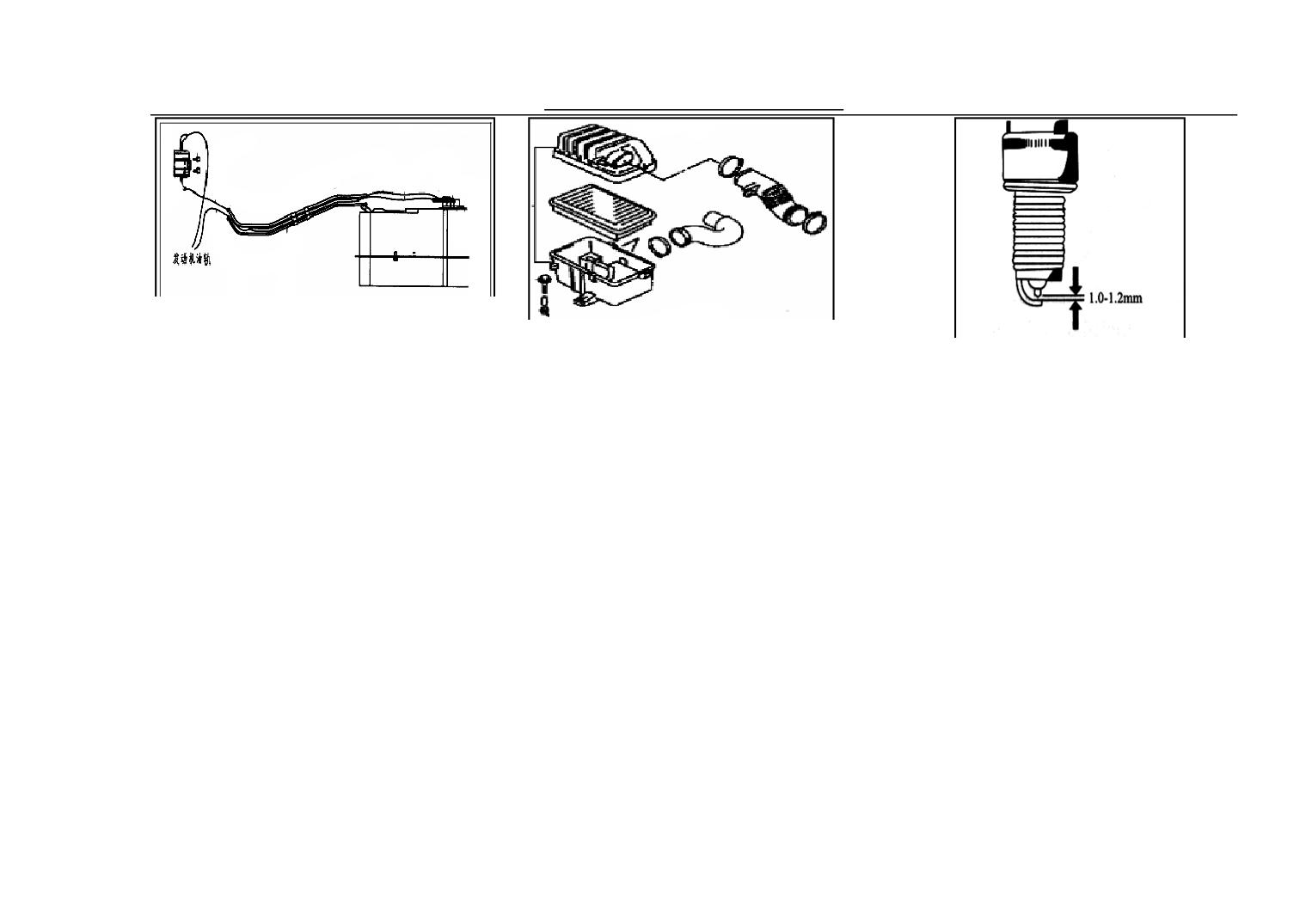
Check/Maintenance Service
There is 0.3MPa in the oil supply
The filter element of the air cleaner
system. While changing gasoline filter and
should be often removed and washed.
The spark plug is F6TC (4C7T) and
oil supply tube and oil return tube and tie-in,
Wash once when running 10000KM
the whorl is M14 *1. 25.
on the pitch road, wash once each time
you should adopt the right fittings from
When there is accumulated charcoal in
while running 2500 kilometers at dirt
Dongfeng YUAN. You had better go to
road.
the plug, it is difficult to produce
Dongfeng YUAN AUTO maintainance
electric spark. Remove the charcoal
station, otherwise may leave your car in
Refer to the service maintainance
with the wire or the needle, and adjust
instruction manual of the electric jet
hidden danger.
series engine of DELPHI system or
the spark plug interval to 1. 0-1. 2mm.
Note:
unite electricity system for the
The interval should be even and the
While replacing the above
dismantlement, clearance and fixing of
same on the electrode level of the
fittings, please pay attention to
the Air Cleaner.
whole centre.
avoiding fire caused by fuel jet.
11. Spark Plug
10. Air Cleaner
The spark plug whose pitch of screw
is incorrect in size is not to be used.
If the whorl is stretched out or
indentation while covering, it will
45
Check/Maintenance Service
gather the charcoal powder in the
exposed whorl part. In this way, when
Note:
Every performance index of air
throttle has been adjusted qualifiedly
According to the situation of the
already when the engine is dispatched
imported vehicles euipped with
from the factory. The user is not
gaoline spray system used in China
allowed to adjust the adjusting screw
dismantle the spark plug or change
and the actual conditions of and petrol
of the throttle by himself, otherwise it
with the correct spark plugging will
product which our country use at
will effect the correctness of the data
Note:
causWhile installing the spark pl
present, the vehicle, while parking for
of the sensor located in air throttle and
ug, please
exert to screw it to prevent damage to the
a long time, should start the engine
then effect the performance and
whorl, then screw it tightly by spanner, the
once every two or three months and
exhaust of the ehole vehicle. If there
screw down moment is 2.5-30N.m.
the time should be 2-3 minutes so as
are some troubles, please pay a visit to
to avoid knot glue of the petrol stop up
Dongfeng Mini Auto Maintainance
the oil gushing out device.
Station.
13. Throttle Valve Block
14. Three -way convertor
12. Oil Sprayer
The exhaust system of the electricity
jet is equipped with three-way
convertor to deal with aftertreatment
46
Check/Maintenance Service
which should be adjusted.
of exhaust from engine; three-way
18.ABS
convertor can reduce the harmful gas
ABS (Antilock Braking System, ABS
effectively.
for short) can prevent wheel from
braking completely suddenly by
automatically and repeatedly adjusting
It is quite easy for three-way convertor
the braking pressure and fully utilize
to be overheated while the gasolines
peak value of the adhesion coefficient
engine working, and which may cause
among the tire and ground and high
the damage of the three-way convertor.
Turn the steering wheel slowly from
lateral force coefficient while applying
In order to protect three-way convertor,
left to right to check its idle stroke.
the brake promptly to gain the
while the driver is in the course of
The idle stroke of steering wheel
manipulation of the automobile while
operating, please refer to instruction &
along the circumference is 0-30mm.
applying the brake and the direction
maintainance manual of gasoline
The turning of the steering wheel
stability, and there is integrated
engine of DELPHI system or unite
should be light and smooth and
control system of electromechanics
electricity systematic electricjet serial
without noise.
combined by shortest braking distance
petrol machine use and maintain the
17. Clutch Pedal
advanced electronic technology and
manual.
mechanical technology.
15. Electric Fuel Pump
The work of ABS systemis automatic,
The fuel-pump is in the fuel tank.
whenever, as long as the apperceive
Note:
Do not drive while the oil mass is
wheel is locked up, it begin to work
insufficiency, otherwise the fuel pump
automatically. Step on the brake pedal
will be burnt for the fuel has been run
out.
directly while applying the brake; do
not step on the brake pedal repeatedly.
The free way of the clutch is 15-25mm,
16. Steering Operation
and it is improper for longer or shorter,
47
Check/Maintenance Service
On decorating road, the braking
stepping on the brake pedal by 294N
Note:
distance of vehicle with ordinary
(30kg)
When ABS loses its function, the
braking system will be shorter than
performance of brake system is same
that of vehicle with ABS.
with that of the common brak system.
Note:
Please use the tire regulated by the
Measure the space between the
instruction manual.
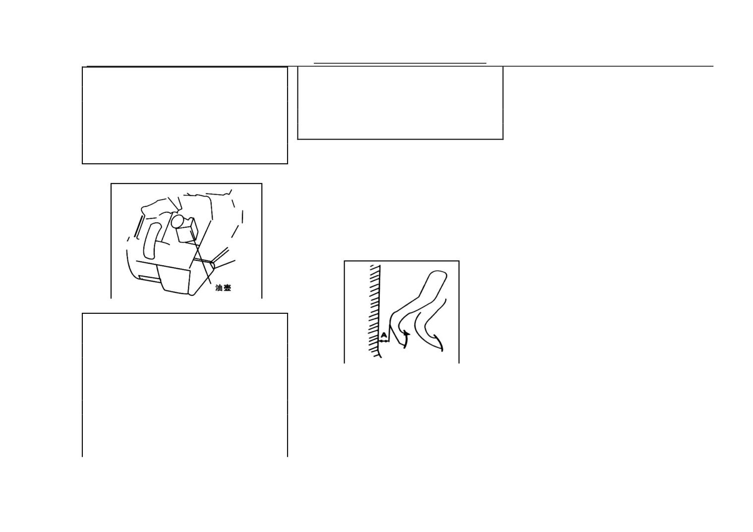
Brake Oil Can
brake pedals, the stool plate of the
The brake oil can lies in the left upper
wainscot and the rubber washer on
19. Brake System
part of the outside of the fron
the pedal are not included.
storehouse clapboard. Check the brake
oil can, if the oil level lies below the
① The braking force is insufficient.
line’MIN’, please supplement the
② The braking is not stable.
brake oil, the trademark for it is JG3.
③ The stroke for the pedals is too
Brake System
big..
④ .Brake blocked
⑤ Brake with noise
⑥ The pedal bounced while stepping
Note:
To the same vehicle, when applying
on.
the brake on some soft road
surface(such as the broken stone road
Hand Brake:
surface, snow road), the braking
Hold the handle brake rod upwards to
When stepping the brake pedal down
distance of vehicle with ABS is longer
Note:
check if the rear wheel stopped , and
completely, the distance ‘A’ between
than that of vehicle without ABS but
check when draw the hand brake rod
Do not mix the different kinds of and
the pedal and the front wall shall not
with common braking system. If the
upwards by strength of 20kg, if the
different types of brake liquid
less than 95mm. And it should be
vehicles with ABS system please
pole stops in (3-8) ratches.And it shall
together, otherwise which may cause
checked and maintained if the
reserve longer brake distances.
the serious damage of the braking
also be checked that when relax hand
following things happan while
system. Do not utilize the old, used or
48
unsealed brake liquid.
Check/Maintenance Service
brake totally, there should be no sense
worn and torn and lengthen its service
① Check the wearing and tearing of
of being blocked.
life,
please
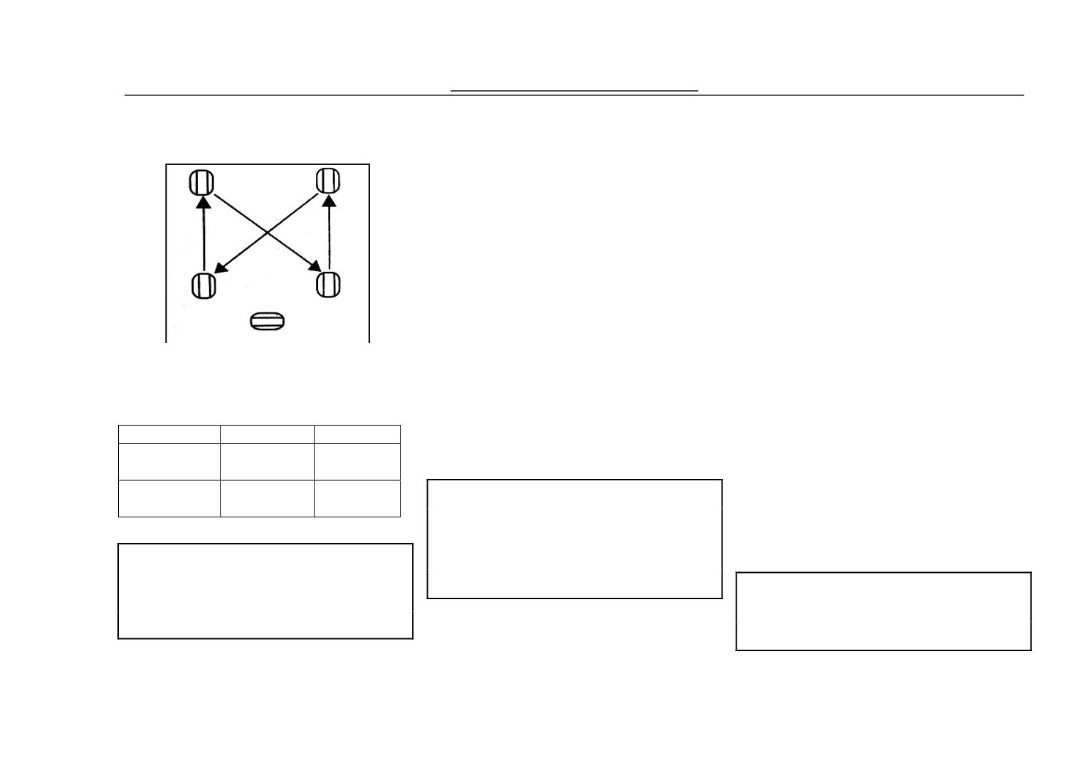
make the tires
the flower stria to make certain that if
transposition when it is running every
20. Tyre
10000km and adjust the air pressure of
it should be changed or not.
front and rear tire to the regulated
② Check if there are abnormal
value (please refer to the pressure
wearing and tearing, crack and
scutcheon on the driver’s side door).
When the air pressure is too low, it
damage for the tire. If yes, please
will cause the tire worn and torn too
change it.
much and difficult to drive and heavy
fuel consumption; while the air
③ Check if there are nail. Carpolite
pressure is too high, the vehicle shakes
or other articles pierce into the tires or
The tire trakemark of this vehicle is
badlly and cause the stability bad and
embed in the flower stria.
165/70R14, and the pressure should be
the middle of the tire will be badly
as follows:
worn and torn.
④Check if the nut looses. While
The air pressure of the tire should be
replacing the tire please use the same
Loading
Fr Wheel
RR Wheel
checked by the pressure gage.
180kpa
220kpa
type, same specification and loading
Zero Load
20. Tyre
capacity tire as the original tire. The
250kpa
290kpa
Fully Loaded
Note:
flower stria for the four changed tires
When pumping the tyre, pls
20. Tyre
should be the same.
slowly pump the tyre and at the same
Note
time check the tyre pressure until it
20.Tyre
The air pressure shall be
reach to the regulated pressure.
Note
measured while it is in the cold
While replacing the tyres, the four
The following check should be carried
condition.
tyres shall be the same type.
out in the course of using:
In order to prevent tire from being
Note:
49
The spare wheel shall be the yellow
steel wheel which can be only used
when emergency.
Taking the spare wheel as the
Check/Maintenance Service
the connection end and erosion will
cause poor contact. If the the white
power is found at the connection end,
it should be clean up and then spread
20.
lubricate grease or waseline.
22. Fuse
The spare tire is put under the floor of
the back of the vehicle, screw the
fixed screw on the rear pumper
counter-clockwise and put down the
spare tire bracket, and remove it. And
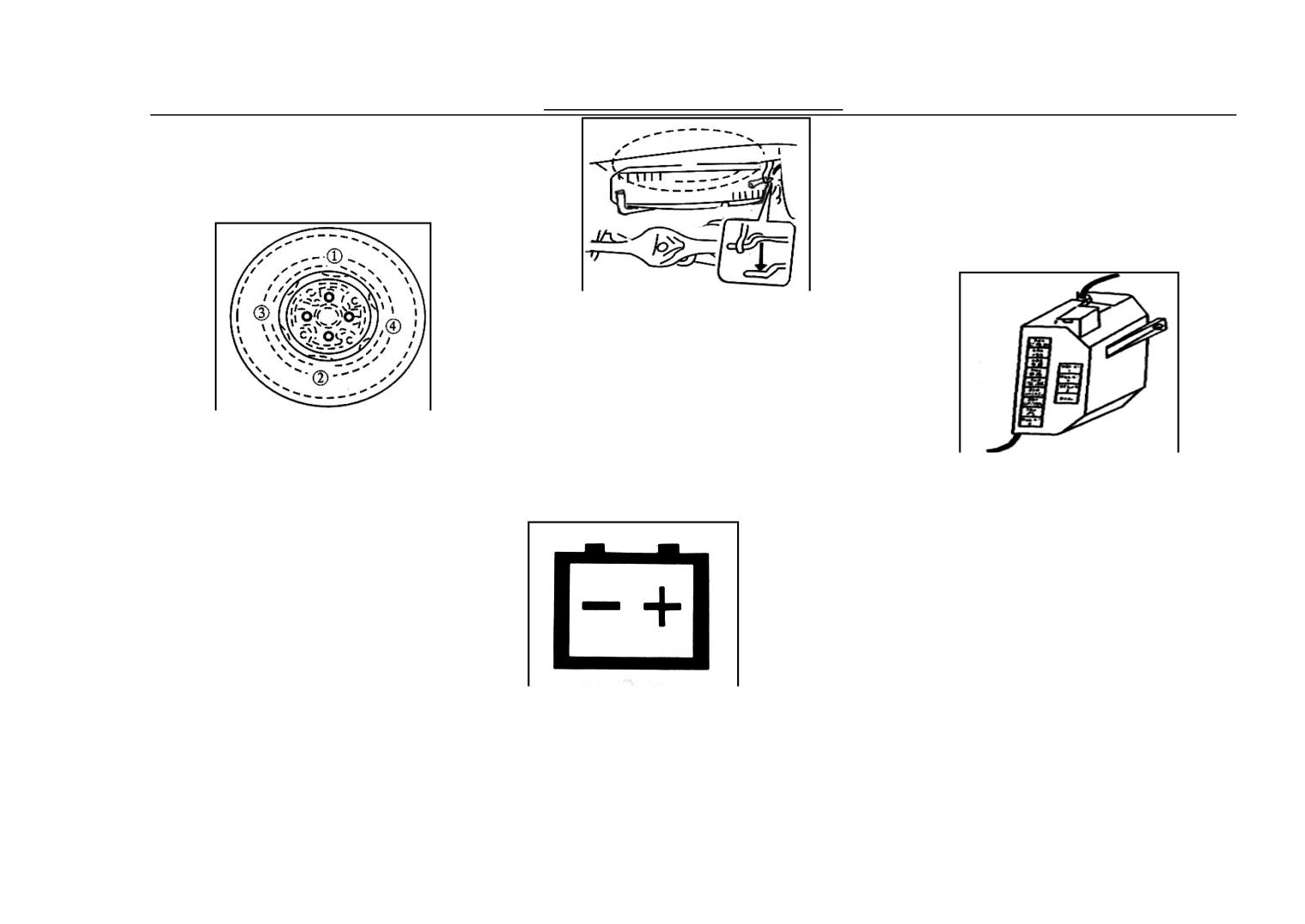
Replacement of the Tyre
the fixing and discharging should be
carried out counter-clockwise to make
① Take off the jack, tool and spare
There are two kinds of fuses, one is
sure its fastness.
tire from the vehicle.
the major fuse and the other kind is
21. Battery
the fuse in every part of circuit.
② Loosen the tire, but do not remove
①Major Fuse: Bear the
the nut.
electric current in the battery directly.
③ Put the jack in a proper position
When it is burnt, no electric
and raise it up.
component can work normally. If so,
④Discharge the wheel.
please check the circuit of the
④ Fix the wheel and change the nut.
The battery electrolyte level should
charging system.
⑥Lower the jack, fix the nut by
always be between lines of ‘upper’
spanner.
and ‘lower’, if the electrolyte is lower
20. Tyre
than ‘lower’, add the electrolyte to the
marking line of ‘upper’. The loose of
50
Check/Maintenance Service
Note
22. Fuse
Note
If the major fuse is burnt,
In order to guarantee that
the users should replace it
Note
there are spare fuse for
instead of using the wire etc as
If the electric machine works
replacement, three 10amp and
substitute which may cause the
without cleaning liquid, it will
15amp fuses will be prepared in
damage of the electric system,
cause damage. Do not use he
the fuse box.
even the fire.
ngine ntifreeze instead of
①Fuse of Branch Circuit
cleaning liquid, or else, it will
The fuse box lies in the left of the
damage the oil paint.
24. Replacement of the Bulbs
pedal bracket. When taking down the
Different Lamp
fuse, first remove the cover of the fuse
23. Air Window Cleaning
Note:
box, and then draw out the fuse. In
Liquid
Please replace the bulb when it cools
order to differentiate the capacity
down.
(amp) position of the fuse, please refer
Halogen lamp is very hot while in the
to the indication diagram on the cover
course of lighting or at the moment of
of the fuse box.
being closed and will damage the skin
and cause fire, please wait till it cools
Note
down and take it off by wrapping it
Users should use the right capacity
with soft cloth.
fuse while changing the burnt fuse,
If the bulb is frequently burnt, it shows
using the aluminum foil or aluminum
that there are some problems with the
wire and other substitutions are not
Check the container for cleaning
circuit. Please go the Dongfeng Mini
allowed. If the fuse is burnt in a very
liquid, if there are not enough cleaning
Auto Maintainance Station for help.
short time, it shows there are big
liquid, please add it
problems with the electric, please go
to Dongfeng Mini Auto Maintainance
Station for help.
51
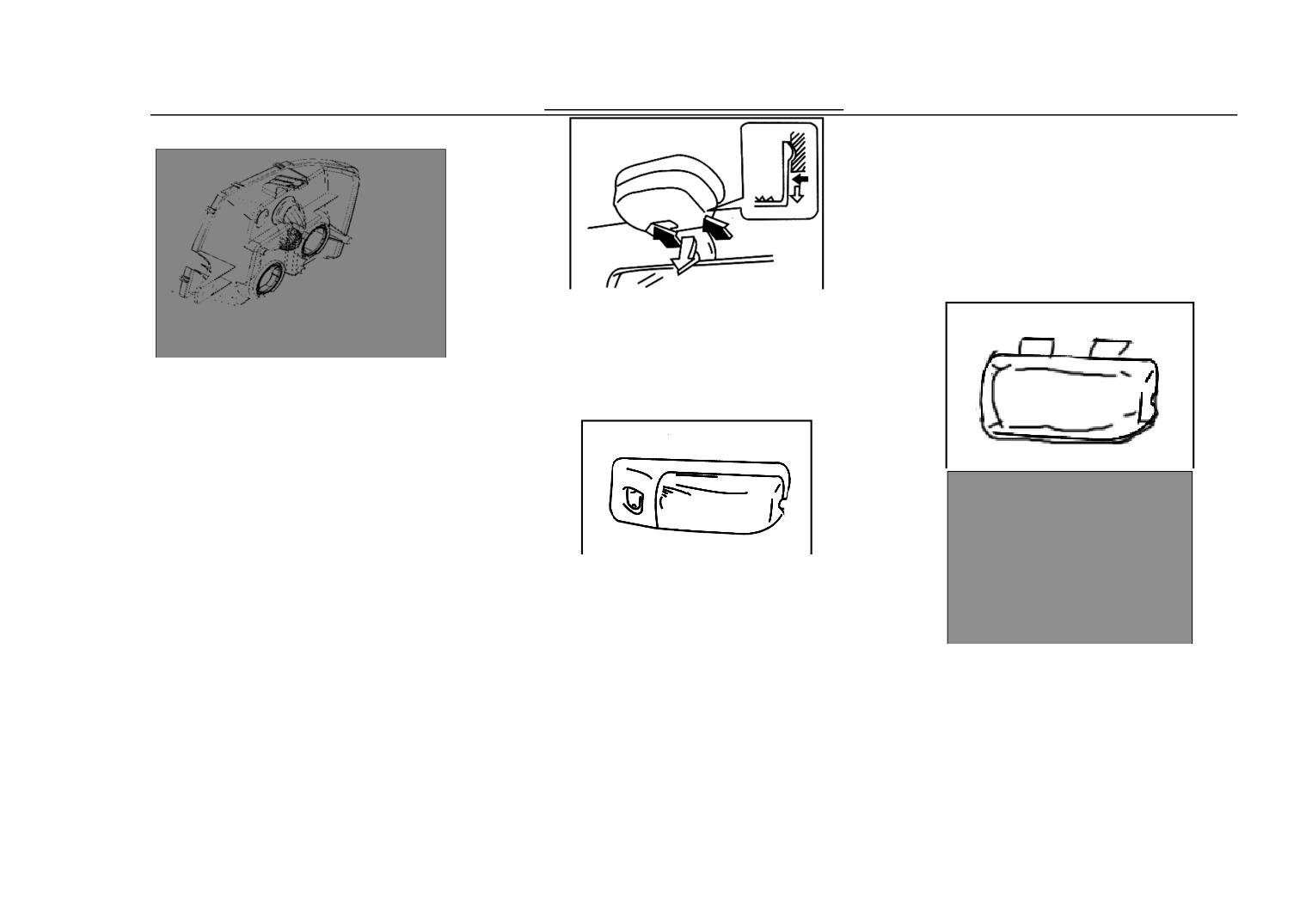
Check/Maintenance Service
be simply pulled out or inserted in.
While removing the round bulb from
the socket, please first press the bulb
in and then contrarotate a little and
then pull out.
24. Replacement of Bulb
Push forward the rear fixing foot
after breaking off relations, take out
box cover backward, you can lift off
24. Replacement of Bulb
bulb for change.
① Open the front storehouse cover
② Remove two screws and draw out
the headlight forwad.
③ Pull out the flashboard.
④ Remove the pressurized rubber.
See the picture, use an opener and
⑤ Push forward the spring making it
wrap it with cloth, then pr down the
release from the hook, then change the
glass cover to replace the bulb.
headlight bulb.
24. Replacement of Bulb
24. Replacement of Bulb
⑥Contrarotate the fender light or
Turning Lights, Side Turning Lights,
Rear Assembled Lights, Liscence
tailstock of the turning lights and then
Lights.
removes the bulbs for replacement.
There are two forms of bulbs (ellipse
24. Replacement of Bulb
or roundness), and the ellipse bulb can
52
Check/Maintenance Service
53
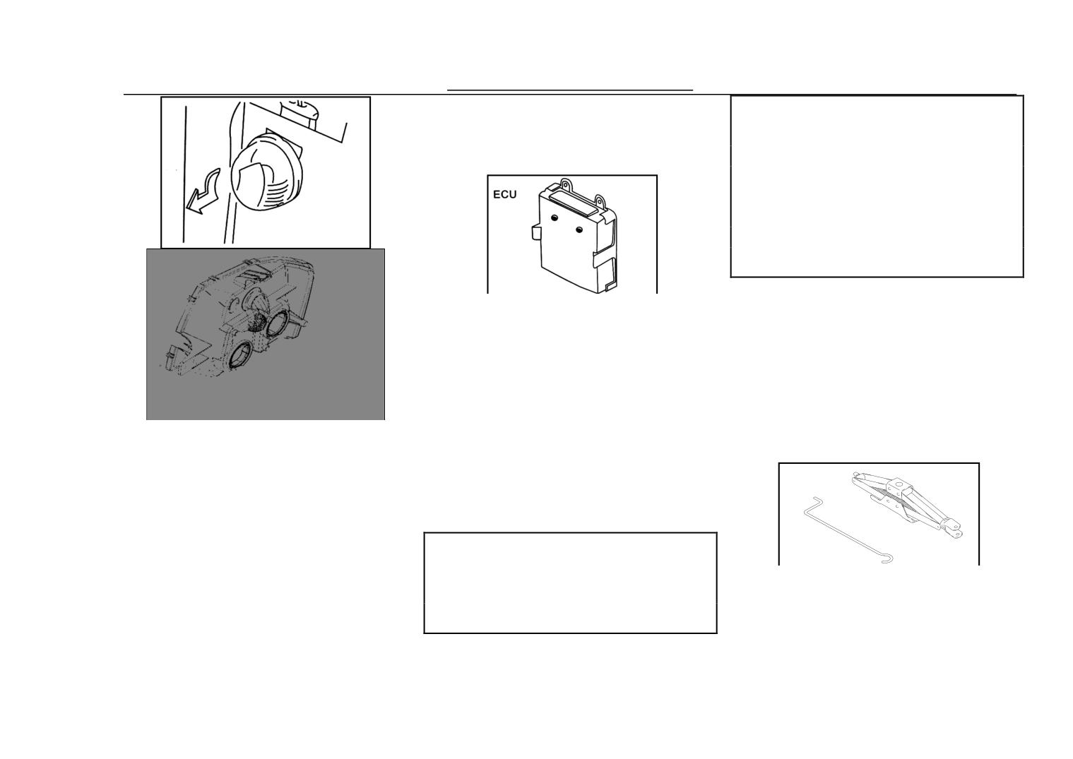
Check/Maintenance Service
tailstock of the turning lights and then
Don't electrification is it dial ECU
removes the bulbs for replacement
plug to insert, is it is it " blow fire "
way carry on circuit is it check to set
25. ECU
up an electric circuit " to adopt to
forbid, is it adopt power of
charger ,etc. carry on starting to
forbid, car body is it should remove
ECU when welding to need
26. Ignition Timing
ECU is the key component of
The integrated electric ignition system
electric control system, inside which
for is a totally electric ignition free of
there are designed process and
adjustment. The system has cancelled such
demarcated data for controlling
parts as bypass and contact point etc., and
running. Do not pull out the cable at
the ignition timing is controlled by the ECU
① Open the front storehouse cover.
will at any cases so as to avoid the loss
27. Usage of Jack
⑥ Remove two screws and draw out
of the data. If there are any troubles,
the headlight forwad.
please go to Dongfeng YUAN Auto
⑦ Pull out the flashboard.
Maintainance Station for help
⑧ Remove the pressurized rubber.
Note
⑨ Push forward the spring making it
Please prevent the ECU from
Jack and rock rod of the jack should
release from the hook, then change the
water while in rainy day or while
be kept in the cover board of the front
washing
headlight bulb
storehouse. After using, please return
⑥Contrarotate the fender light or
25. ECU
to the storehouse and make sure they
54
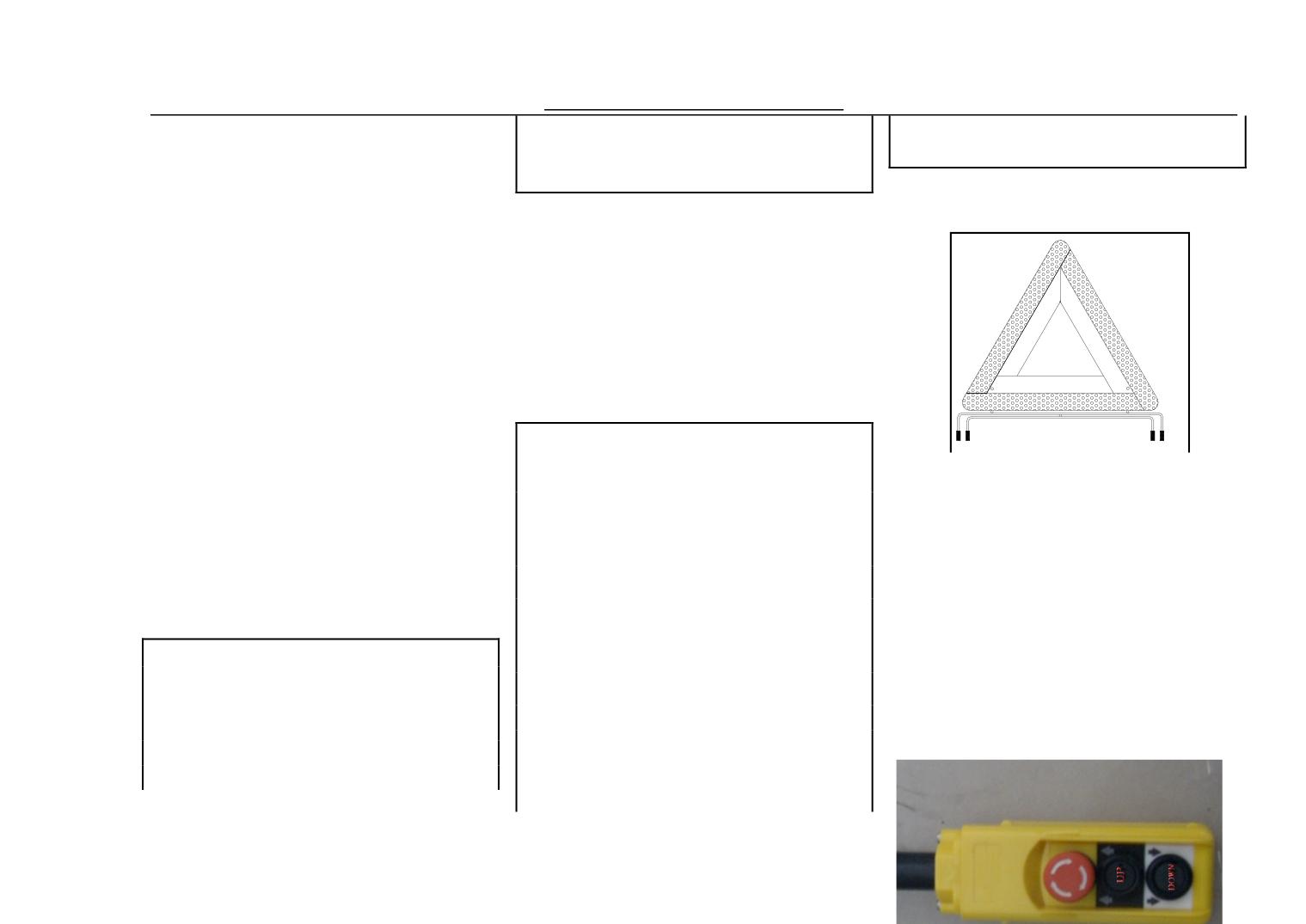
Check/Maintenance Service
And any person shall not be under
yellow is pressuer over high, red over
have been fixed up firmly
the vehicle while jacking up to
low, should be changed.
While using the jack, the vehicle shall
prevent the damage to people
be put in the horizontal and hard
28. Extinguisher
29. Triangle Warning Plate
ground. If you stop the vehicle on the
The usal and operation of
road, please turn on the emergency
Extinguisher
Take out the extinguisher and pull
light
the cover then spurt extinguishing
Lock up the parking brake, and put
agent in 1.5M distance of root of fire.
Pressure extinguisher valve until
gearshift rod in the reverse gear, and
finishing spurting extinguishing agent.
fix the the tire on the cross of the
And inversion use not allowed.
rising angle by chock
Note
Put the jack under the jacking
Please refer to the Instruction
1.
Every
2 years change
position and upright jack up the
extinguisher with 450g, and every 4
Manual for the operation guide of
years change extinguisher with 500g,
vehicle steadily and slowly to the
Triangle Warning Plate
even not use.
proper position; do not jack up the
2.Extinguisher with 450g should
Note:Engine is on working during
vehicle too high
change a new after use in appointed
switch is ON. Unless is out of line
fatory, while 500g can be fulled the
operation.
Note
agent and reuse.
Be careful if the vehicle rises
3.450g exginugisher should be
vertically in the course of jackup.
checked in appointed factory per year.
If the jack begins to incline, please
30. Operating controller
4.Check the index during green
correct it to the right position.
Jackup on the slope is not allowed.
area or not for 500g extinguisher with
pressure gauge. Green is natural and
55
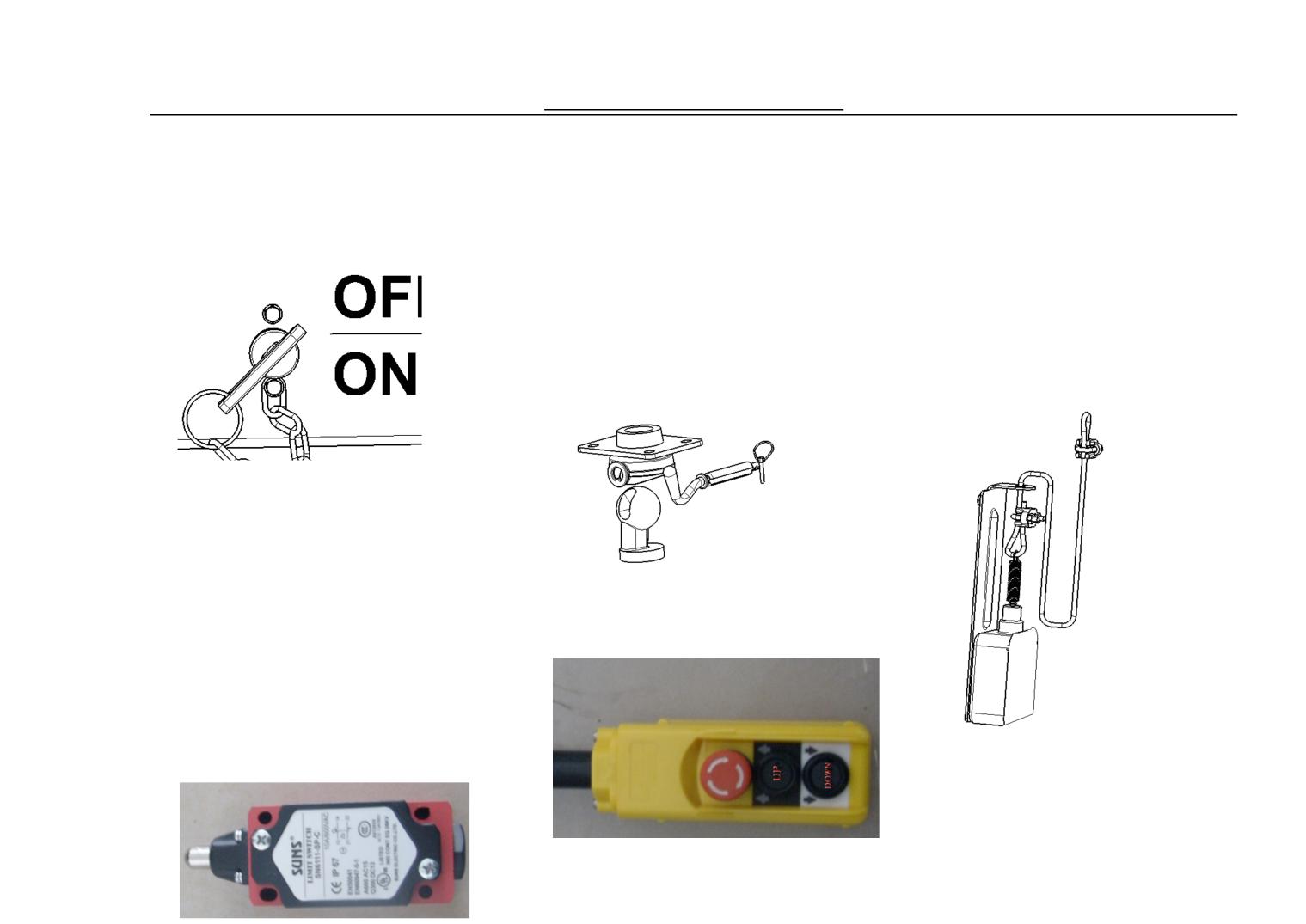
Check/Maintenance Service
Press UP botton, and keep the normal
speed. When trun over to some angle,
31 .Trurning Over and Side
① Pull switch to ON.
tightwire pull the switch to limit the
① Stop the car on flat floor.
location, then hydranlic pressure
Note the height of room when turn
power off, cargo box stop turn over.
over to behind, and insert the ring of
When the lifting stop fails, the
limited location, then put double bolt
hydraulic cylinder’s max range is
into double groove hole, with bolt ring
going to limite the angle of box
of limited location, and check
turn-over.
equipment correct or not.
② Take out the lift controller, press
UP button, the hydraulic pressure
①Open lift switch to ON
motor and buzzer beging working,
① Take out the controller from cabin.
people apart from cargo box.
When trun over to some angle,
tightwire pull the switch to limit
the location, then hydranlic
pressure power off, cargo box stop
turn over.
Left turn
①Put single bolt into left single
56
蜂鸣器开关
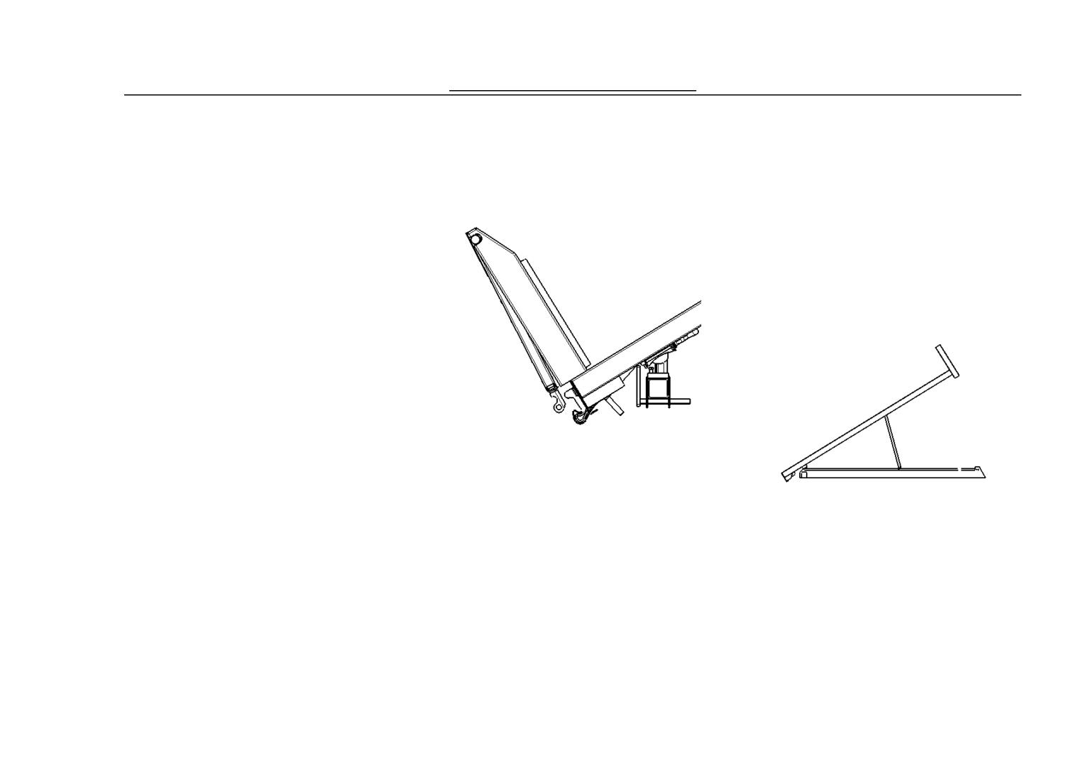
Check/Maintenance Service
groove when turn the cargo box to
regarding connecting rod as axle
①Side plate opened by manual.
left,with ring of loctation limited, then
rotation that makes latch hook rotate
There are lock on the side plate, and
put the double groove bolt into left
at the same time, and makes latch
lock with cargo box. When close side
rear groove round hole, equip limited
hook get rid of box rear plate hinge,
plate, the lock clip is in lock station.
ring bolt, and check the equipment
then realizes box rear plate open
Need open outer handle bar on the
correct or not.
automatically.
side plate to open the side plate. Outer
② Then operate as above ②③ in
handle bar drives the lock interior
trun over operation.
construction move to make side plate
shaft pin downward so that to separate
Right turn
from the side plate lock, then open the
① Put single bolt into right single
box side plate.
groove when turn the cargo box to
right,with ring of loctation limited,
then put the double groove bolt
into right rear groove round hole,
equipe limited ring bolt, and check
the equipment correct or not.
When cargo box in normal location,
②Then operate as above ②③ in
rear plate can not be closed
turn over operation.
automatically, should with manual.
operation of rear plate of cargo box
Press the hand shank of rear plate
Rear plate of cargo box be open
starting connecting rod, make the box
②Then operate as above ②③ in
automatically when the cargo box turn
rear plate back to the hinge match
to some angle. Mainly because the
turn over operation.
position, then loosen the hand shank,
movement relationship
between
operationg of equip stay bar.
make the latch hook and hinge shaft
system of rear plate starting
Use the stay bar when turning to some
pin fit then the box rear plate will be
connecting rod and the starting of box
angle without loading, adjust the flip
closed.
rear side-plate back plate. Rear plate
angle, to ensure the top of stay bar in
operation of side plate of cargo box
starting connecting rod system is
its safety area, achieve the purpose of
57
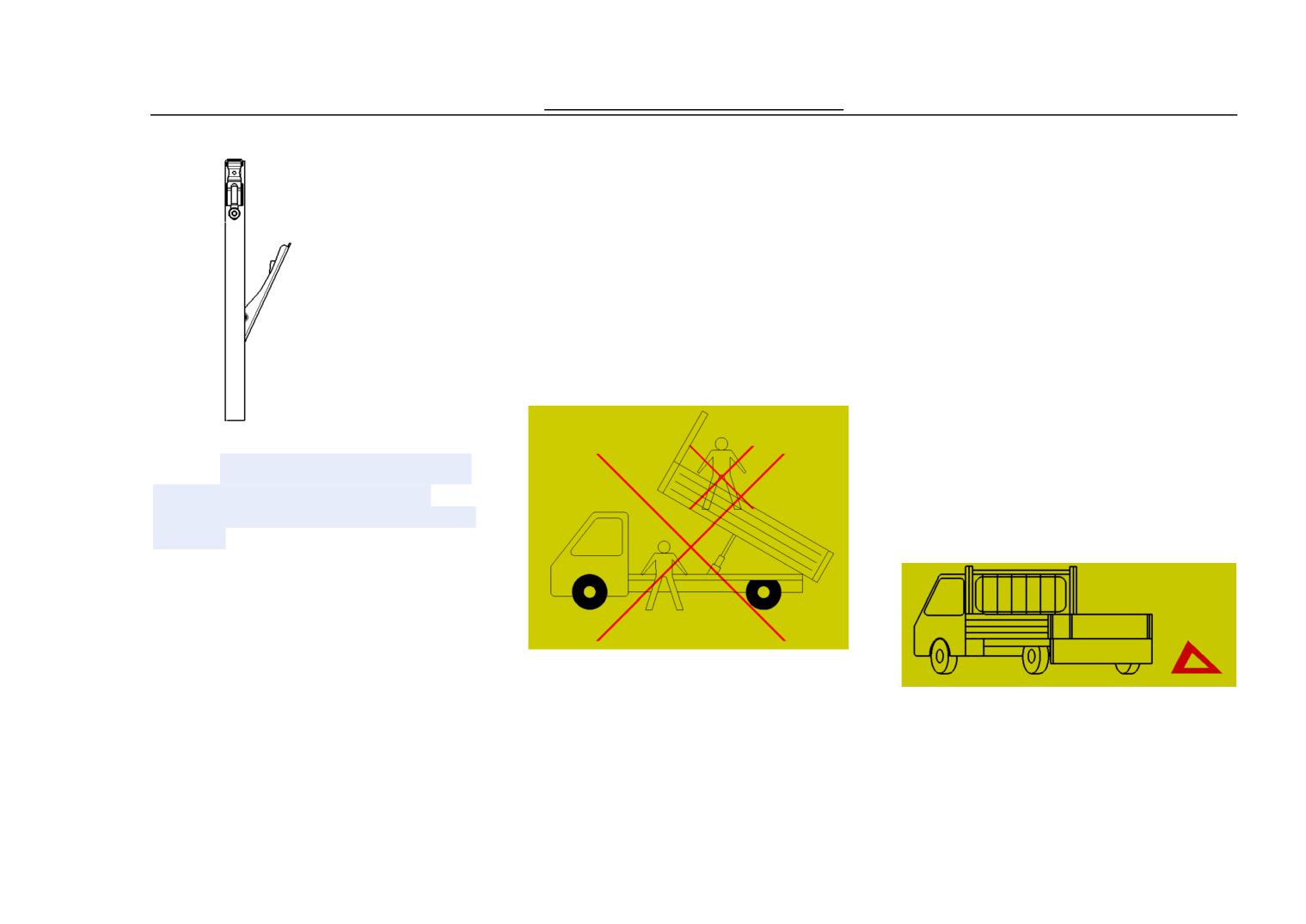
Check/Maintenance Service
safety.
under the vehicle.
explosive or sticky material are
Notice: when the dumper is at
allowed to be transported by
work, the surrounded
dumper truck;
environment should be noticed ,
Notice: If the cargo box can
if there are flammable things
not be lowered due to the battery
around the dump are forbidden.
failure or low battery, during
Note: It may lead to accidents
Notice: while dumping, nobody
operation, the user need to
use the stay bar when goods have not
is allowed to stand on the cargo
replace or charge the battery, or
been full discharge, only use for
box.
inform the repair plant
checking and maintaining cargo box.
nominated by the factory. And a
triangle plate should be placed
Note for operation of lift
around the box to warn the
Note: nitial use, the vehicle should be
passers-by. No manual operation
loaded in accordance with the initial
requirements in order to avoid mechanical
are allowed to perform to lower
damage.
the cargo box。
Note:If need full loading please put
the goods into cargo box in low place
to avoid parts damage.
Note: Lift the cargo box the car
Notice: the vehicle could not
should be in horizontal position to
exceed 10km/h when the cargo
avoid the accident of over flip.
Notice: When performing
Notice: while the cargo box is
box is fully lowered to the
dumping operation, personnel
lifting and descending , no
original position;
should stay away from the
people are allowed to stand
Notice: No flammable,
dumper when hearing the buzzer
58
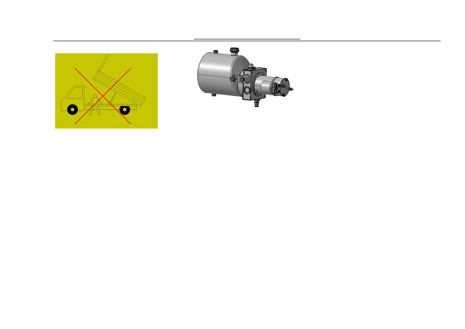
Check/Maintenance Service
alarming;
operations are allowed to the
cargo box。
External lubricating spot:1)
ball joint of the hydraulic
cylinder;2)joint of frame ball
joint and the stand ball joint;3)
latching mechanism of the cargo
box;
Rated wattage of the hydraulic
Notice: Unauthorized
type of lubricant and the
motor:800W; Rated rpm:
personnel must not use and
interval between two refills:
4000r; Rated voltage:12V;
operate the power switch of the
The lubricant should be made
Rated current:67A。
dumper truck;
from lithium, and should be
Notice: the applicable
Pump : Rated pressure :
refilled and replaced based on
temperature of the hydraulic
8MPa;Rations to the motor:
the use of the vehicle.
system of the dumper truck is
Dump systems hydraulic oil: model
0.625;
HM 46: HM hydraulic oil developed
-10˚C-40˚C。
Notice: if the power fails
from the antirust and antioxidation
Hydraulic motor:
when the cargo box is lifting,
hydraulic oil, it has high alkaline zinc,
low alkaline zinc, zinc and ash-free
the manufacturer should be
high-neutral-type and other products,
informed to appoint service
which according to 40 ˚ C
center or technician to conduct
Sports viscosity is divided into four
repair, non-professional must
grades 22,32,46,68.
not operate. No forcible Hydraulic oil introduction and note:
59
Check/Maintenance Service
recommended by the manufacturer or
l)To maintain the cleanliness of hydraulic
(3)Storage and use, fuel containers and
the product supply applies to the pump
systems, shou be the timely removal the
tools must be clean to prevent oil
sludge and metal shavings of the fuel tank.
load limits.
contamination
Note: After
5000Km drived, filter
(2)Reference indicators to change oil,
(4)The oil is mainly used in steel -
should be changed.
all the equipment parts should be cleaned to
steel pairs of hydraulic
prevent impurities mixing into oil and
pumps. Friction material for other
affected
hydraulic pump, the pump must be
Ⅵ . Check & Maintenance Service
60
Check/Maintenance Service
Period
Km×1000
10
20
30
40
50
60
70
80
moon count as standard confirm
1. Daliy inspection
Failure
maintain time form. Every inspection ,
Daliy inspection is a necessary
3Fuel Level
adjust
, lubricate should stipulated
work for driver. The conditions of the
14Door Lock
time go on according to form strictly
vehicle changes every day, so please
with other maintenance work.
15Rear Mirror
check it before driving, which can
Note
16Licence Plate
The maintence items with mark
help find the problems and solve them
2 、 Regular Check and
‘*’ should be carried out by the
before driving to enable to be safe.
Maintainance
special maintainer. While regarding
1 Fan belt
to items without
‘*’ can be do
3、Regular Maintainance Perid
2 Engine oil
maintenance according to the
and Items
instructions, and if you think you
3 Cleaner
The following form will introduce
cannot do that, please go to the
4 Battery Electrolyte Level
some checking items; we can find
special maintainer’s of Dongfeng
problems while checking and take
5 Engine Coolant
Yuan.
measures accordingly. The running
6 Stroke of Brake Pedal
kilometers and months will be the
7 Tire
standard maintenance time. The check ,
4 、 Signs for Regular
adjustment, lubricant and other
8 Free way of Clutch Pedal
maintenance service should be strictly
Maintenance
9 Turning Operation
subject to the stipulated time in the
‘G’ means change
10Indicator Light & Indicator
form.Make form recommend several
‘R’ means needing to be lubriacant.
Meter
project of checking emphatically,
‘X’ means screw to the regulated
through is it pinpoint the problems to
torque.
1Lighting System
check , take the pertinence measure in
‘J’ means checking.
12 Instruction of Electric Jet
time. With go kilometer count or
‘T’ means adjustment.
61
Check/Maintenance Service
Months
6
12
18
24
30
36
42
48
Engine
1.Fa(Water Pump、 Compressor)
Drive Branch Belt ( Strain 、
-
G
-
G
-
G
-
G
Abrasion )
*2.
Camshfte Synchronization
-
J.T.G
-
J.T.G
-
J.T.G
-
J.T.G
Tooth Belt(Strain, abrasion, damage)
*3. Valve Gap
-
J.T.
-
J.T.
-
J.T.
-
J.T.
*4. Engine Bolt(cylinder cover,
-
X
-
X
-
X
-
X
manifold toggle)
5. Oil fillter
G
G
G
G
G
G
G
G
6. egine oil
Replace for every 5000km
7. Engine coolant
Infuse at any time
*8. Soft Tube and Tie-in of Colling
System( Soft Tube and Tie-in of
-
J.T.G
-
J.T.G
-
J.T.G
-
J.T.G
Colling System(leaking ,damaging
etc.)
*9. exhaust system
-
J.T.G
-
J.T.G
-
J.T.G
-
J.T.G
5、Maintenance
Periods
Km×100
10
20
30
40
50
60
70
80
Items
0
month
6
12
18
24
30
36
42
48
Ignition
*10.
-
J.T.G
-
J.T.G
-
J.T.G
-
J.T.G
Ignition Coil(damamged, deformed)
*11. Spark Plug
G
G
G
G
G
G
G
G
*12.Ignition Timing
J.T.
J.T.
J.T.
J.T.
J.T.
J.T.
J.T.
J.T.
62
Check/Maintenance Service
Fuel System
13.
Air
Cement or asphaltum
Clean while driving for every10000km, replace for every 40000km
Cleaner
road
Gravel Road
Clean while driving 25000km, replace for every 40000km
*14. Fuel Box, fuel pipe and tie-in
J.T.G
-
-
J.T.G
-
-
-
J.T.G
*15 Fuel Cleaner
G
G
G
G
G
G
G
G
Exhaust Control of Crankcase
*16. Exhaust Soft Pipe & Tie-in
J.T.G
-
J.T.G
-
J.T.G
-
J.T.G
-
*17.
J.T.G
-
J.T.G
-
J.T.G
-
J.T.G
Fuel Steam Storing Device
*18. PCV Valve
-
J.T.G
-
J.T.G
-
J.T.G
-
J.T.G
Periods
Km×100
10
20
30
40
50
60
70
80
Items
0
monthes
6
12
18
24
30
36
42
48
Electric Equipment
*19. Electric Wiring, Connect & Lamps
-
J.T.G
-
J.T.G
-
J.T.G
-
J.T.G
Chassis & Body
*20Clutch
J.T.
J.T.
J.T.
J.T.
J.T.
J.T.
J.T.
J.T.
*21.
Brake
Fluid(Liquid
J.T.G
J.T.G
J.T.G
G
J.T.G
J.T.G
J.T.G
G
Mass,Leaking)
*22.Brake Pedal(Stroke)
J.T.G
J.T.G
J.T.G
J.T.G
J.T.G
J.T.G
J.T.G
J.T.G
*23. Manual Brake Rod &
J.T.
J.T.
J.T.
J.T.
J.T.
J.T.
J.T.
J.T.
63
Check/Maintenance Service
Cable
*24. front: Brake disk & cliper
J.T.G
J.T.G
J.T.G
J.T.G
J.T.G
J.T.G
J.T.G
J.T.G
*25. Rear: Brake Drum &
J.T.G
J.T.G
J.T.G
J.T.G
J.T.G
J.T.G
J.T.G
J.T.G
Brake Shoes
*26. Brake Soft Pipe &
J.T.G
J.T.G
J.T.G
J.T.G
J.T.G
J.T.G
J.T.G
J.T.G
Pipeline(Leakage, damage)
27. Tire(Abnormal Abrasion,
J.T.G
J.T.G
J.T.G
J.T.G
J.T.G
J.T.G
J.T.G
J.T.G
Abnormal Air Pressure)
28. Wheel & Boss Nut
J.T.G
J.T.G
J.T.G
J.T.G
J.T.G
J.T.G
J.T.G
J.T.G
64
Check/Maintenance Service
Periods
Km×1000
10
20
30
40
50
60
70
80
Items
monthes
6
12
18
24
30
36
42
48
*29.Bolt & Nut(Elasiticity)
-
X
-
X
-
X
-
X
*30.
Steering
Wheel(Gap,
J.T.G
J.T.G
J.T.G
J.T.G
J.T.G
J.T.G
J.T.G
J.T.G
Elasiticity)
Cooling System
*31. Refrigerant
*32.Brake System
J.T.
J.T.
J.T.G
J.T.
J.T.
J.T.
J.T.
J.T.G
J.T.G
J.T.G
*33.Compressor
-
-
-
-
-
-
R
R
*34Condensor
Check at any time
*35.Evaporator
-
-
-
J.T.
-
-
-
J.T.
*36. Desiccator
-
-
-
G
-
-
-
G
*37. Refrigerate Pipeline
-
X
-
X
-
X
-
X
65
Emergency Measurement
Ⅶ、Analyzing & Eliminating the Malfunction
1、Malfunction of Engine System
Problems
Reasons
Solutions
Starting Problems
1、Failure of Ignition System
Replace
1.1 Damage of the Protecting Device
Repair or Replace
1.2 Failure of the Spark Plug
Repair or Replace
1.3 Joint of High Voltage Damping Wire Loose or
Replace
being Damaged
1.4 Damage of Ignition Coil
2、Failure of Fuel System
2.1 Lack of Gasoline
Infuse Gasoline
2.2 Gasoline Cleaner Blocked
Clean or Replace
2.3 Fuel Pipeline Defiled or Blocked
Clean
2.4 Electric gasoline pump doesn’t work
Repair or Replace
66
Emergency Measurement
2.5Impurity Fuel (eg. Including water)
Rectify
3. Lack of Crock Pressure
Screw Down or Replace
3.1 Spark Plug not Screw Down or Damage of
Adjustment
Gasket
Repair or Replace
3.2 Incorrect Valve Gap
Repair or Replace
3.3 Leakage of Cylinder Cover Gasket
3.4 Piston, piston ring or abrasion of Cylinder
4.Others
4.1 Rupture of Timing Belt
Replace
4.2 Vacuum Soft Pipe inconnect
Reliable Connect
Decrease/ lack of the
1. Malfunction of Ignition System
Engine Power
1.1 Inprope Spark Plug Gap or Burnt
Adjust or Replace
1.2 Poor Connect/ Damage of High Voltage
Repair or Replace
Damping Wire
2. Malfunction of Fuel System
Clean
2.1 Block of Fuel Soft Pipe or Oil Pipe
Clean or Replace
2.2 Block of Gasoline Cleaner or Air Cleaner
Repair or Replace
2.3 Oil Supply of Gasoline not enough
Clean or Huff
2.5 Trouble with Piston Valve
Replace
2.6 Broken gasket of intake branch pipe
Replace
2.7 Incorrect fuel trademark
3. Insufficient Crock Pressure
As Above Mentioned
67
Emergency Measurement
4. Others
4.1 Brake Problems
Repair or Replace
4.2 Clutch Skidding
Adjust or Replace
4.3 Connect Flex or Vacuum Soft Pipe Break Off
Reliable Connect
Unstable Idle Speed of
1. Trouble with Fuel System
Engine
1.1 Block of the Air Cleaner
Clean or Replace
1.2 Leakage of Intake Branch Pipe
Replace
2. Mafunction of Ignition System
2.1 Inproper or Burnt Spark Plug Gap
Adjust or Replace
2.2 breakoff or creepage of High Voltage Damping
Replace or Connect
Wire
3. Lack of Crock Pressure
As mentioned above
4. Others
4.1 Connect Flex or Breakoff of Vacuum Soft Pipe
Reliable Connect
4.2 Failure of PCV of Crankcase
Replace
Abnormal Noise in the
1. Valve Noise
inner side of the Engine
1.1 Inproper Valve Gap
Adjust
1.2 Abrasion of Valve Rod & Valve Guide Pipe
Replace
1.3 Failure or Damage of Valve Spring
Replace
1.4 Distort or Curve of Valve
Replace
2. Abrasion of Piston, piston ring and Valve
Repair or Replace
68
Emergency Measurement
3. Rod Noise
3.1 Rod Bearing Abrasion
Replace
3.2 Winch Pin Abrasion
Repair or Replace
4.Crank Shaft Noise
4.1 Bearing Abrasion
Replace
4.2 Crank Shaft Neck Abrasion
Repair or Replace
4.3 Bearing cover bolt flex
Screw Down
4.4 Gas of crank shaft thrust-piece too big
Replace the thrust-piece
Engine Superheating
1. Insufficiency of Coolant
Complement Coolant
2. Air Resistance in Cooling Sytem
gas freeing & adding coolant
3. Loose of Water Pump Belt
Adjust
4. Malfuction of Thermostat
Replace
5. Poor Performance of Water Pump
Replace
6. Too Much Begrime in Cylinder Body AND
Repair or Replace
Cylinder Cover
Clean or Repair
7. Block or Leakage of Radiator
Choosing the right kind
8. Incorrect Engine Oil Kind
Replace or Clean
9. Block of Engine Oil Cleaner or trap valve
Add
10. Insufficient of Engine oil
Repair or Replace
11. Poor Performance of Oil Pump
Repair or Replace
12. Brake Seizure
Repair or Replace
13. Clutch Skidding
Replace
14.Damage of Cylinder Cover Gasket
Consumption of Engine
1. Leakage of Engine Oil
Oil
1.1 Flexible Discharging Oil Bolt
Screw Down
1.2 Bolt of the Oil Case Flexible
Screw Down
69
Emergency Measurement
1.3
Replace the Sealling Glue
Seal Glue of Oil Case deterporate or Break
Replace
1.4 Leaking of Oil Seal
Replace
1.5 Damage of the Cylinder Gasket
Screw Down
1.6 Engine Oil Filter not being Screwing down
Screw Down
1.7 Leaking of the Engine Oil Pressure Annunciator
Screw Down or Replace
1.8Oil Leaking of Cylinder Cover
Screw Down
1.9 Oil Line of the Cylinder Blocked and leaking
2. Engine Oil Entering the Firebox
2.1 Piston Ring Locked
Clean of Sand
2.2 Abrasion of Piton Ring & Groove
Repair or Replace
2.3 Abrasion of Piton Ring & Cylinder
Repair or Replace
2.4 Piston Ring not Stagger as regulated
Adjust
2.5 Abrasion of Valve Oil Seal
Replace
2.6 Abrasion of Valve Rod
Replace
2.7 Damage of Cylinder Washer
Replace
2.8 Breakoff of Rocker arm Screw
Screw Down or Replace
High Consumption of
1. Malfunction Of Fuel System
Gasoline
1.1 Fuel Tank, Carburetor or Leakage pipeline
Repair or Replace
1.2 Block of Air Cleaner
Repair or Replace
2. Malfunction of Ignition System
2.1 High Voltage Damping Wire Flexible or
Connect or Replace
Creepage
Adjust or Replace
2.3Malfunction of Spark Plug(Inproper Gap, Burnt,
accumulated carbon)
3. Insufficient of Cylinder Pressure
As Above Mentioned
4. Others
70
Emergency Measurement
4.1 Poor Valve Seat
Repair or Replace
4.2 Brake Seizure
Repair or Replace
4.3 Malfunction of Thermostat
Replace
4.4 Abnormal Tyre Pressure
Adjust
2. Clutch problems
problems
reasons
solution
Clutch Skid
Inproper stroke of Clutch Pedal
Adjust the Free Stroke
Clutch Flake Abrased or with Oily Soil
Replace Clutch Flake
Deformation of Compressive Plate or Flywheel
Replace Clutch Flake, Clutch
Surface
Compressive Board or Flywheel
Diaphragm Spring Weak
Replace Clutxch Cover
Clutch Cable Rust
Replace Cable
Hard Seperation of
Inproper Free Stroke of Clutch
Adjust Free Stroke
Clutch
Diaphragm Spring Weak or Abrasion of Reed
Replace Clutch
Input Spline Rust
Lubricating
Damage or Abrasion of Transmission Input Shaft
Replace Input Oil
Spline
Replace Clutch Flake
Serious Sway of Clutch Flake
Replace Clutch Flake
Clutch Flake Abrased or with Oily Soil
71
Emergency Measurement
Vibration of Clutch
Brightening of Clutch Flake (Like Glass)
Repair or Replace the Clutch Flake
Clutch Flake with Oily Soil
Replace Clutch Flake
Separate Bearing Smoothly Skid on the Guard Ring
Lubricate or Replace Input Shaft
of Input Shaft Bearing
Bearing Guard Ring
Sway of Clutch Flake or Poor Connection
Replace Clutch Flake
Torsional Spring in the Clutch Flake Weaken
Replace Clutch Flake
Loose Rivet of Clutch Flake
Replace Clutch Flake
Deformation of Compressive Plate or Flywheel
Replace Clutch Cover or Flywheel
Surface
Screw Down Again or Replace
Fixing Wahser of Engien Becoming Weak, and
fixing Washer
Fixinjg Bolt or Nut Becoming Flexible
Clutch Sounding
Abrasion or Damage of Separate Bearing
Replace Separate Bearing
Abrasion of Front Input Shaft Bearing
Replace Input Shaft Bearing
Loose of Clutch Flake Hub
Replace Clutch Flake
Crakes in Clutch Flake
Replace Clutch Flake
Compressive Plate or the Diaphragm Spring Loose
Replace Clutch Cover
Clutch Jammed
Clutch Flake Soked with Oil
Replace Clutch Flake
Serious Abrasion of Clutch Flake
Replace Clutch Flake
Rivet Coming out of Flake
Replace Clutch Flake
Torsional Spring Weaken
Replace Clutch Flake
72
Emergency Measurement
3. Malfunction of Transmission
Problems
Reasons
Solutions
Off Gear
Abrasion of Gearshift Forked Shaft
Replace
Abrasion of Gearshift Fork or Synchronizer Gear
Replace
Cover
Replace
Elasticity of Setting Spring Weakened or damaged
Replace
Abrasion of Input shaft or Main Shaft Bearing
Replace
Abrasion of Tooth Sleeve etc.
Fix
Hatch Spring Ring breaking off
Not Off Gear
Elasticity of the Synchronizer Spring Weakened or
Replace
the Spring Broken
Replace
Deformation of Gearshift Axle or Gearshift Fork
Gearshift Troubled
Incorrect Clutch Pedal Stroke
Adjust
Deformation or Break of the Cluch Friction Disc
Replace
Damage of Clutch Compressive Plate
Replace Clutch Cover
Abrasion of Synchronizer Alligatoring Ring
Replace
Deformation of Gearshift Axle
Replace Gear
Replace
Noise
Insufficiency Lubricant or the Inproper Type
Complement or Replace
Damage or Abrasion of Bearing
Replace
Dmage or Abrasion of Gear
Replace
Damage or Abrasion of Synchronizer Alligatoring
Replace
Ring
Replace
Abrasionor Damage of Gear Sleeve etc.
73
Emergency Measurement
4. Malfunction of Differential Gear
Problems
reasons
solution
Gear Noise
Gear Oil going bad or including water
Replace Oil & Re-infuse
Insufficient Gear Oil or Incorrect Kind
Replace Oil or Infuse
Incorrect Gap between Taper Driving Gear & its
Adjust
Driven Gear
Adjust or Replace
Inproper Connect between Taper Driving Gear & its
Driven Gear
Replace or Screw Down Again
Loose of Setting Bolt of Taper Driven Gear
Replace
Damage of Differential Gear or Driving Gear
Bearing Noise
Gear Oil going bad or including water
Replace Oil & Re-infuse
Insufficient Gear Oil or Incorrect Kind
Replace Oil & Re-infuse
Damage of Taper Driving Gear Bearing(noise
Replace
sending off while Gliding)
(Noise while rotating,) Damage of axle bearing of
Replace
differential gear or the back axle bearing
Oil Leakage
Chock of Vent Blocked
Clean
Abrasion or Damage of Oil Seal
Replace
Too Much Oil
Adjust Oil Level
74
Emergency Measurement
5. Malfunction of Steering System, Suspension System, Wheel and Tyre System
Problems
Reasons
Solutions
Wheel
Tyre not matching or Asymmetry
Replace
Running(deviating )
Inproper Tyre Pressure
Adjust the Tyre Air Pressure
Rupture of Spring
Replace the Spring
Belt Tyre Warped by Transverse Force
Replace the Tyre
Maladjustment of Front Wheel Alignment
Check & Adjust the Front Wheel
One Running Wheel Seizure
Alignment
Or Rear Suspension Flexible, Bent or Damaged.
Repair Brake
Screw Down or Replace the
Suspension
Abnormal Abrasion or
Sagging or Damage of Spring
Replace Spring
over-Abrasion of Tire
Imbalance of Tire
Adjust to make it Balance or
Maladjustment of Front Wheel Alignment
Replace Tyre
Trouble with Strut (Shock Absorber)
Check & Adjust Front Wheel
Bad Road Condition
Alignment
Overloading
Replace Strut
Tyre not Transposition
Replace Tyre
Abrasion or Sagging of Wheel Bearing
Replace Tyre
Sway of Wheel or Tyre
Replace or Reposition
Insufficient of Air Pressure of Tyre
Replace Wheel Bearing
75
Emergency Measurement
Replace Wheel or Tyre
Adjust Air Pressure of Tyre
Wheel Shocked
Inproper Strut (Shock Absorber)
Replace Tyre
Replace Strut
Front Wheel Shake or
Imbalance of Tyre or Wheel
Banace the wheel or replace the tire
Jump
Abrasion or Damage of Wheel Bearing
and/or wheel
Abrasion of Steering Horizontal Coupling Bar
Replace the wheel bearing
Abrasion of left/right front Suspension Wall Round
Replace the end of turning sidelong
Head
coulping bar
Immoderate wheel radial jump
Front suspension arm
bulge or damage on the tire
Repair or replace wheel and/or tire
Tyre/wheel radial jumping overloadingly
Replace the tire
Maladjustment of Front Wheel Alignment
Replace tire or wheel
Turning Driving Rodbecoming flexible or being
Check & Adjust the front wheel
abrased
alinment
Fixing bolt of turning gear box becoming flexible
Screw down or replace the driving
rod
Screw down the turning gear bolt
Turning Problems
Inproper Charge Pressure of Tyre
Charge the Tire to the Proper
Sluggish of Steering Global Scolex or L/R Global
Pressure.
Scolex of Suspension Arm
Replace the Steering Global Scolex
Maladjustment of Front Wheel Alignment
or the front Suspension Arm
Inproper Adjustment of Rack and Pinion
Check & Adjust Front Wheel
Sluggish of Steering Wheel
Alignment
Check & Adjust the Torque of the
Rack & Pinion
Repair or Change
76
Emergency Measurement
Turning Windage too Big
Abrasion of Wheel Bearing
Replace Wheel Bearing
Bolt of Turning Gear Case Loosened
Screw Down
Incorrect Adjustment of Rack & Pinion
Check & Adjust Torque of Rack &
Abrasion of Turning Axle Universal Joint
Pinion
Abrasion of the turning sidelong coupling bar end
Replace Universal Joint
or its inner side global joint.
Replace the turning sidelong
Abrasion of Global Joint of Left/Right front
coupling bar end or turning sidelong
suspension arm.
coupling bar
Replace Front Suspension Arm
(Poor return(Turning)
Jamming of turning sidelong coupling bar end.
Replace the turning sidelong
Jamming of Global Joint
coupling bar end
Jamming of Steering Volume
Replace Front Suspension Arm
Poor Lubricant of Rack & Pinion
Repair or Replace
Maladjustment of Front Wheel Alignment
Check, Repair or Lubricate the Rack
Improper Adjustment of Rack & Pinion
& Pinion
Improper Charge Pressure of Tyre
Check & Adjust Front Wheel
Alignment
Check & Adjust Torque of Rack &
Pinion
Adjust Air Pressure of Tyre
Noise while Turning
Bolt of Turning Gear Case Loosened
Screw Down
Wheel Bearing Damaged or with other problems
Replace
Abrasion of the turning sidelong coupling bar end
Replace
Improper Adjustment of Rack & Pinion
Check & Adjust Torque of Rack &
Pinion
77
Emergency Measurement
Abnormal Noise with
Abrasion of unworkable or loose of the turning
Replace the Turning Sidelong Coupling
Front Wheel
sidelong coupling bar end, global joint (left/right
Bar End, Front Suspension Arm, global
front suspension arm), inner side global joint of the
joint and tramsmission shaft joint.
coupling bar or tramsmission shaft joint.
Repair or Replace
Damage of Strut or fixing piece
Replace
Abrasion of suspension arm bush
Screw Down Bolt, Replace Bush
Stabilizer bar becoming flexible
Screw Down Wheel Nut
Nut of wheel becoming flexible
Screw Down the Bolt or Nut
Bolt or nut of the suspension shelf becoming
Replace Wheel Bearing
flexible
Replace Spring
Damage of the wheel bearing or other problems
Infuse Lubricant or Replace Strut
Damage of the spring of the suspension shelf
Bearing
Poor Lubrication or Abrasion of Strut Bearing
Replace
Abrasion of the joint of stabilizer bar
Sway while Turning or
Tyres not Matching or Air Pressure Odds
Replace Tyre or Charge the Tyre to
Turning with Poor
Front Suspension Arm Ball Joint and Turning Sidelong
Proper Pressure
Stability
Coupling Bar End Becaming Flexible
Replace suspension arm or the end
Shock Absorber/Stanchion or Fixxing Piece Going Wrong
of turning sidelong coupling bar.
Stablization Pole Becoming Flexible
Replace Strut or Repair Fixxing
Damage or Sagging os Spring
Piece
Inproper Adjustment of Rack & Pinion
Screw Down or Repair the Stablization
Inproper Front Wheel Alignment
Pole or Cover
Connecting Ball Joint of The Stablization Pole Becoming
Replace Spring
Flexible
Check & Adjust Torque of Rack &
Pinion
Check & Adjust Front Wheel
Alignment
78
Emergency Measurement
Turning Instable while
Abrasion of Wheel Bearing
Replace Wheel Bearing
Brake
Damage or Sagging of Spring
Replace Spring
Charge of Tyre Insufficient
Charge the Tyre to Proper Pressure
Front Wheel Alignment Inproper
Check & Adjust Front Wheel
Alignment
Height of the actural
Rupture or Sagging of Spring
Replace Spring
vehicle disaccord
Overloading
Check Carrying Load
Inproper Use of Spring
Replace Spring
Feel loose while driving
Shock Absorber or Strut with Troubles
Replace Shock Absorber or Strut
Suspension suppressed to
overload
check load
the bottom
failure of shock-absorber or support
change the shock-absorber or
deflexion or shaking
spring shows failure or drooping
support
while body truning
stabilizer bar loose
change spring
failure of shock-absorber, support or installation
tighten the stabiliaer bar scew or
parts
change bush ot joint
damage of spring or droop
change support or installation parts
overload
change spring
check load
tyre turns into spill
Fr. Support is defect
change
wheel bearing abrasion
change wheel bearing
tyre and wheel over-run out
change tyre and fahuun
abrasion of Fr. Cantilever joint
change Fr.cantilever
tyre not balance
regulate tyre balance
79
Emergency Measurement
6. Warm braw system failure
problems
causes
resolution
when the warm-braw fan
fan fusing
change fuse, check short circuit
puts through the power
fan resistance doesn’t work
check circuit condition
it doesn’t work
fan monitor doesn’t work
change monitor
circuit or ground connctoion failure
repair when necessary
output temperature is
control dragline crack or winding
check the dragline
wrong
air damper damage
repair damper
air pipe block
repair air pipe
warm braw module leak or block
change warm braw module
warm braw pipe leak or block
change the pipe
7. AC system failure
problems
reasons
resolution
80
Emergency Measurement
no cooling air output (AC
AC doesn’t work
Recall, pump-out and fill in cryogen.
doesn’t work)
1) no cryogen
check the fuse,heating ventilation
2) fusing
change AC fuse and check
3) the switch of AC and fan are wrong
short-circuit or not
4) low idling
check AC and fan switch
5) AC thermisor is wrong
check and regulate AC idling
6) AC water-temperature sensor is wrong
check AC thermistor
7) high and low voltage switch is wrong
check AC water-temperature sensor
8) top AC relay is wrong
check high and low voltage switch
9) accelerate cut switch is wrong
check top AC relay
10) circuit or ground connection is wrong
check accelerate cut switch
11) AC amplifier is wrong
repair as needed
check AC amplifier
compressor is wrong(doesn’t work)
check compressor thermol protector
1) compressor thermol protector
check electronmagnetism clutch
2) electronmagnetism clutch is wrong
tighten or change drive belt
3) drive belt is loosened or damaged
check compressor
4) compressor is wrong
freezing fan doesn’t work
change fuse and check if
1) fusing
short-circuit
2) AC freezing fan relay is wrong
check freezing fan relay
3) circuit or ground connection is wrong
repair as needed
4) AC freezing fan module is wrong
check freezing fan module
81
Emergency Measurement
blowing machine module doesn’t work
check blowing machine module
1) blowing machine module resistance is wrong
resistance
2) ACand fan switch is wrong
check AC and fan switch
3) circuit or ground connection is wrong
repair as needed
4) blowing machine module is wrong
check blowing machine module
No cooling air or not cool
cryogen is shortage or overloaded
check cryogen condition
enough (AC system is
freezing machine block
check system leak, check freezing
normal)
evaparation block or frozen
machine
AC thermostor resistace is wrong
check evaparation
AC controller is wrong
check AC thermostor resistance
expansion valve is wrong
check AC controler
cistern/drier block
check expansion valve
drive belt is slipping
check cistern/drier machine
electronmagnetism clutch is wrong
check or changdrive belt
No cooling air or not
compressor is wrong
check compressor
enough air (AC system is
AC system has air
change cistern drier machine,
normal)
air leak from top evaporation or air-pipe
pump-out and fill cryogen, repair
warm braw and ventilating device system is wrong
when necessary
blowing machine module is wrong
check evaporation assy
AC system exsists overloaded compressing oil
check warm braw assy
check blowing machine fan assy
pump-out AC system compressing
oil and change another compressor
82
Emergency Measurement
cooling air output off and
Failur of the connection of the circuit
Repair when necessary
on
Failur of the expansion valve
Check the expansion valve
Excessice moisture in the AC system
Change the fluid/airer, refill the
Failur of the disconnection switch of high-speed
cryogen
Failur of the AC controller
Check the failure
of
the
Failure of the electromagnetic clutch
disconnection switch of high-speed
Failur of the compressor overheat protector
Check the AC controller
Excessive refill of the cryogen
Check the electromagnetic clutch
Check the compressor overheat
protector
Check the capacity of the cryogen
Cool air only during
Cool air only during high-speed driving
Check the condensor
high-speed driving
Inadequate refill of cryogen
Checki ts
Air in the AC system
Replace the airer, and the evacuate
Slipping of the drive belt
and refill the cryogen
Failure of the compressor
Check or replace the drive belt
Check the compressor
83
Emergency Measurement
No cool air only during
Failure of the disconnection switch of high speed
Check the disconnection switch of
high-speed driving
Excessive refill of the cryogen
high speed
Freezing of the evaporator
Check the cryogen
Check the evaporator
Check the thermistor of AC
Cool air not strong
Jam in the evaporator
Check the evaporator
Leak in the cooling device or the pipe
Check the thermistor of AC
Failure of the motor of air blower
Check the blower motor
Failure of the circuit or ground connection
Repair when necessary
Noise in the compressor
Rotary valve fails
Replace
Bearing valve fails
Replace
Cylinder or axel fails
Replace
84
Emergency Measurement
Noise
in
the
The bearing fails
Replace
electromagnetic clutch
Clutch disk damaged
Replace
Inadequate cool air
The gasket is damaged
Replace
The leaf valve fails
Replace
No rotation
The rotary valve is blocked, causing the jam of the
Replace
cylinder and/or the axle
Replace
The electromagnetic clutch is stuck
Replace
The rotation components get stuck due to
inadequate oil
85
Emergency Measurement
Oil or fluid leak
Sealing of the axle is damaged
Replace
O ring damaged
Replace
Brake system failure
8.
Problem
Reasons
Treatment mothod
Noise when braking
Brake pipe leakage
Identify and repair leaking parts
Brake disc or brake pad (block) dirted by the oil
Clean or replace
Brakes overheating
Repair or replacement
Brake drum brake shoe is bad
Repairing, so that the correct access
Brake shoe linings are oil or water
Replacement
Brake pad (block) linings wear
Replacement
Brake Cylinder Damage
epair or replacement
Brake caliper assembly failure
Repair or replacement
(If fitted) LSPV improper adjustment of sensor
Check or adjust
length of the spring
Exhaust
The system with air
Replacement
Damage to the sensor spring LSPV
Replacement
LSPV damage to the rings (if fitted)
Refer to ABS System
Anti-lock braking system (ABS) failure (if fitted)
86
Emergency Measurement
Uneven brake (brake work
Brake pad (block) friction lining and / or the brake
replacement
uncoordinated)
shoe linings of water or oil
Check the automatic adjustment of
Brake drum brake and brake shoe clearance disorders
mechanical
(automatic adjustment of mechanical failure)
Replacement
Brake disc brake and / or loss of brake drum circle
Uniform inflation
Uneven wheel pressure
Repair or replacement
Brake Cylinder Failure
Required adjustment
Bad front wheel adjustment
Should use the same axis the same tire
Not match the tires on the axle
tread Check the hose to soften the tubing
Poor brake lines or hose flow
is damaged, with new brake hoses and a
Brake caliper assembly failure
new double-decker steel replacement.
Loose suspension components
Check the piston is stuck or
Loose caliper
slow-moving, should be properly
lubricated bushing sliding calipers,
caliper should slide.
Check all suspension mounting
Inspection, bolt tightening torque in
accordance with regulations
Noise (not brake squeak
Friction and wear of front brake linings
Replace linings
when issued)
Locking rear brake too
LSPV improper adjustment of sensor length of the
Check or adjust
early (for a car equipped
spring
Replace assembly
with LSPV)
LSPV assembly failure
Brake locking (for cars
ABS system failure (ABS-antilock braking system)
Refer to ABS System
equipped with ABS)
87
Emergency Measurement
Too much pedal travel
Partial failure of brake system
Check the brake system, when necessary,
Inside the brake master cylinder brake fluid reservoir
for repairs.
insufficient
Brake fluid with a qualified endorsement.
An air brake system (pedal like riding in the sponge on
Check brake system for leaks, with or
the weak)
without air.
Can not adjust the rear brake system (automatically
Check the warning lights to the system
adjust mechanical failure)
when necessary to exhaust.
Bending brake shoe
Exhaust
Rear brake shoe wear
Automatic adjustment of mechanical
repair, adjust rear brake
Replacement brake shoe
Replacement brake shoe
Brake Back-bit delay (the
Master cylinder piston can not return the correct
Master cylinder repair
release of the pedal, the
position
Check the hose is softening, oil is
brake pedal can not go
Brake lines or hose blocked traffic smaller
damaged, with new brake hoses and a
back in time in situ)
Parking brake on the rear brake adjustment is not
new double-pipe replacement.
Brake return spring is not within the return bit or
Inspect and adjust the technical
damage
requirements
Ying or parking brake pull rod slow response
Replacement
Wheel brake caliper piston pump or a stuck
Repair or replacement
Caliper piston seal within the severe wear
Repair if necessary
ABS (Antilock Braking System) fault
Replace piston seal
See ABS System
88
Emergency Measurement
Pedal hopping (when the
Damage or loose wheel bearings
Replace wheel bearings
brake pedal beat)
After steering knuckle or axle deformation
After the replacement of steering knuckle
Radial brake disc is too large or does not meet the
or axle
technical requirements of parallel
Check, if you do not meet the technical
Loss of rear brake drum circle
requirements of the brake disc to be
replaced or repaired
Check the runout, where necessary,
repair or replace the brake drum
Brake Noise
Brake shoe polish or stick with impurities
Repair or replacement
Brake shoe wear or distortion
Replacement
Loose front wheel bearings
Replacement
Deformation or loose floor mounting bolts
Replace or tighten the mounting bolts
After starting the engine
Release the parking brake is not
Release the parking brake, check and
brake warning light
Brake fluid is not enough
turn off the brake warning light filling
Implementation of the
Brake pipe leakage
the brake fluid
brake, the brake warning
Brake warning light circuit fault
Check for leaks parts, repair, filling the
light
ABS (anti-lock braking system out) fault (if fitted)
brake fluid
Brake pipe leakage
Overhaul brake light circuit
Brake fluid is not enough
Refer to ABS System
Check for leaks parts, repair, filling the
brake fluid
Filling the brake fluid
Parking brake, the brake
Brake warning light circuit fault
Replacing light bulbs or repair circuits
warning light does not
shine
89
Emergency Measurement
After starting the engine
ABS (Antilock Braking System) fault
Refer to ABS System
ABS warning light (if
fitted)
Implementation of the
ABS (Antilock Braking System) fault
Refer to ABS System
braking, ABS warning
light (if fitted)
9. ABS system failure (optional)
Check 1
Steps
Operation
Yes
No
1
1) When the ignition switches off, remove the
Proceed to step 2
Replace ABS wheel speed sensor
ABS wheel speed sensor.
assembly.
2)Measure the resistance of ABS sensors
between terminal connectors are in the
1.4-1.8KΩ range (at
20
° C,
68
° F
environment)
2
1)Disconnect the ignition switch
Proceed to step 3
ABS wheel speed sensor cathode
2) Disconnect the ABS control module
circuit with the power supply short
connectors
circuit
3)Check first with the sensor and the ABS
control module terminal is properly connected
4)If all goes well, then close the ignition
switch and measure the positive voltage
between the sensor terminal of module plug
connector and ground columns, whether the is
OV.
90
Emergency Measurement
3
1)Disconnect the ignition switch
Proceed to step 4
Open-type short circuit grounding
2)Connect ABS wheel sensor connectors
connect
3)Measure the resistance between positive
terminal of ABS wheel speed sensors and plug
connector module negative, between positive
terminal and ground.
Check the measured resistance value is reached
the scope of above step 1.
1)Remove ABS wheel speed sensor
Proceed to step 5
Cleaning, repair or replace
4
2)Check sensor damage or whether there exists
a foreign body, to see if it is in good working
condition.
5
Visual ABS wheel speed sensor mounting holes
Proceed to step 6
Cleaning, repair or replace
(front wheel) or remove rear drum (rear wheel)
and check the following points
If rotor teeth miss or damaged teeth
If no foreign body attached
Whether the eccentric rotor
If the gap of wheel bearings is too huge
Good condition?
6
1)Install the ABS wheel speed sensor to the
Proceed to step 7
Replace ABS wheel speed sensor
steering knuckle at .
2)As per required torque, tight sensor bolt and
check the gap between sensor and steering gear
ring, everything is okay?
91
Emergency Measurement
7
See chapter "front wheel speed sensor
With a well-known
Replace the sensor and re-check.
information" content, check that the output
ABS
control
voltage or waveform.
module replaced
and re-check
Check 2
Steps
Operation
Yes
No
1
1)Turn the ignition switch off, remove the
Proceed to step 2
Exclude or replace the ABS hydraulic
device from the ABS hydraulic connectors.
unit
2)Check the ABS hydraulic unit solenoid
valve terminal if it is connected correctly.
3 ) If correct, then under this section,
"hydraulic device, the solenoid valve check"
to check the contents of the resistor and the
solenoid valve if it is shorted to ground.
If it is condition?
2
1)Disconnect the ignition switch
Proceed to step 3
"W / G" circuit open
2)Measuring solenoid valve connectors,
wiring harness side of the terminal "W / G"
and the resistance between the Ground, to see
if it’s connected?
92
Emergency Measurement
3
1 ) Remove the ABS control module
Proceed to step 4
"R", "R / W", "B1", "B1 / W", "Y", or "Y
connector
/ W" short circuits and power supply
2)Check the ABS control module terminal
"A1",
"A2", "A7", "A8", "B12", "B13", whether the
current valve circuit connected correctly.
2 ) If the connection is good, measure
to-ground voltage of module terminal A1,
A2, A7, A8, B12 or B13- (ignition switch is
closed), to see if it’s OV.
4
1)Disconnect the ignition switch
With
a
"R", "R / W", "B1", "B1 / W", "Y", or "Y
well-known ABS
/ W" circuit is open, poor contact or
2 ) Connect the connectors to the ABS
control
module
short-circuited.
hydraulic unit.
replaced
and
3)Measure the ground resistance of module
re-check
terminal A1, A2, A7, A8, B12 or B13, to see
if it’s connected.
10、Power system failure
Problem
Reason
Treatment
Turn on the ignition switch, the
Fuse blown
Check the fuse
engine is not running, the charging
Lights burned out
Replace Lamp
light does not shine
Loose wire connections
Tighten fittings
IC regulator or field coil failure
Check the generator
Bad brush and slip ring
Repair or replacement
93
Emergency Measurement
When the engine is running, charging
Loose or worn drive belt
Adjust or replace drive belt
light does not go out (batteries need
IC regulator or alternator failure
Check charging system
frequent recharging)
Line fault
Repair line
11、Variety of lamps, light system failure
Headlight failure
Problem
Reason
Treatment
Headlights are not bright
Bulb damage
Check that the lamp
Faulty headlight switch
Check the headlight switch
Headlights (left and right) are blown fuse
Check the fuses left and right, if
Faulty wire or ground
necessary, to be replaced. (If
replacement, check whether the
short-circuit)
Repair line
Only a headlight is not lit
Bulb damage
Check that the lamp
Headlight (left or right) fuse blown
Check the fuse, if necessary, should
Faulty headlight switch
Check the light switch front
Faulty wire or ground
Repair line
Front anti-fog lamp failure
Problem
Reason
Treatment
94
Emergency Measurement
Front anti-fog lamp doesn’t work
Bulb damage
Check the lamp
Fog light fuse blown
Check the fuse, if necessary, should be
Front anti-fog lamp switch doesn’t
replaced. (If replacement, check if it’s
work
short-circuit)
Front anti-fog lamp relay doesn’t work
Check front anti-fog lamp switch
Front headlamp switch doesn’t work
Check relay
Wire or ground connection doesn’t
Check switch
work
Repair line
One of anti-fog lamp doesn’t
Bulb damage
Check lamp
work.
Wire or ground connection doesn’t
Repair line
work
The failure of turn signal and emergency warning light
Problem
Reason
Treatment
Flash frequency is too high, or
Damage to the side of the bulb
Check lamp
only one side Flash
Lamp is not configured correctly
Check lamp
Turn signal / emergency alarm relay
Check relay
failure
Repair line
The open or resistance between turn
Repair line
signal / emergency alarm switch and the
Check the fuse and replace
Doesn’t flash
light is too large
If replacement, check if it’s short-circuit
Wire or ground connection doesn’t
Check the bulb and check the line
work
Check relay
Backup horn or reversing lights blown
Check at the beginning
95
Emergency Measurement
fuse
On or resistance between battery and
switch is too large
Turn signal / alarm relay faulty
Combination switch or alarm switch
doesn’t work
Flash frequency is too low
Supply voltage is too low
Check recharging system
Turn signal / urgency alarm relay faulty
Check relay
Problems
Reasons
Solution
Braking warning light is
Stop brake is not released
Release the stop brake, check and turn
on when starting the
Short of brake liquid
off the braking warning light and infuse
engine
brake pipe leaking
brake fluid.
Braking warning light is
Circuit problems with the brake warning light
Check the leaking position, repair and
on when braking
Trouble with ABS(if there is)
infuse brake fluid.
brake pipe leaking
check the circuit of breaking light
Short of brake liquid
Please see ABS
Check the leaking position, repair and
infuse brake fluid.
Infuse brake fluid
Braking warning light is
Trouble with the circuit of braking warning light
Replace the bulb or repair the line
not on while stop braking
96
Emergency Measurement
ABS warning light will be
Trouble with ABS
Please see ABS
on while starting the
engine (if it has)
ABS warning light will be
Trouble with ABS
Please see ABS
on while braking(if it has)
97
Emergency Measurement
Ⅷ 、Disposition of Emergency
headlight is opened, try to turn thee
state. If headlight becomes too dark or
1. Starting System Not Work
ignition switch to " START " position
goes out totally, it generally shows the
①In a situation that the
in order to confirm the storage battery
storage battery electricity exhaust or
98
Emergency Measurement
poor connecting of wiring end. After
not bend over the battery.
respectively. Pay attention that the
Confirmation, charge the storage
cable shall not be near to the belt
②Do not expose the battery to direct
battery or repair the connect point.
pulley, belt or fan.
fire or make it under the spark.
③Start the engine of the vehicle with
③Keep your eyes & skin away from
②If the headlight keeps being on,
battery first, then start the engine of
the storage battery acid. If any part of
the vehicle without electricity.
the skin touches and holds the acid
please check the fuse. If there are still
liquid of storage battery, wash the
④Do counterclockwise according to
problems, there may be big electrical
injured area completely with water
the above orders to backout the
immediately, and ask doctors and
connected cables.
problems; you should go to Dongfeng
nurses for help.
Note
Please follow the following
If battery is installed again
YUAN Auto for repair.
after being removed, the original
2. Instruction of Storage Battery
instruction while parallelizing the
designed condition will lose in
Connect Start
ECUand you may find the idle
battery to start:
If the engine can not start because of
speed is too high or too low
①Put one good 12V storage battery
the storage battery, you can connect
when re-starting this is not a
close to vehicle, and make the link
oNotend storage battery in parallel or
trouble and it is unnecessary to
cable reach to the storage battery.
storagStorage battery can produceing
adjust, the ecu will adjust the idle
Make the two vehicles close to each
inexplosive gas, and the causticitygh
speed to the regulated value after
and the big output
other but not touch each other while
elacid in which
running 15 seconds at idle speed.
electric current may cause to be
using the storage battery on the other
burnt. In order to reduce
vehicle.
personnel's injury, you should
②Connect the two ends of the first
follow following information
cable with the anode of the
3. Overheating of Engine
when work near storage battery.
corresponding battery, and two ends of
Under the abominable condition
the cable shall be connected to the
of driving a vehicle, the tempreture of
cathode of the corresponding battery
engine will temporarilygoo beyond. If
①Make you eyes protected, and do
99
Emergency Measurement
the temperature form of the engine is
letting out is found, it is forbidden to
pointedkout beyond the regulated
value, so:
use the engine before getting rid of the
①Turn off the A/C.
trouble.
③ Parking the vehicle in a safe place,
and make the engine running for
c. If no leaking is found, you can
several minutes at idle speed till
infuse coolant to store liquid barrel
the value of the water thermometer
Traction of the Vehicle
go down to the safe range.
and then to the radiator carefully if
If need traction, please send for
③If the tempreture of the water still
professionalist or special maintainer of
does not go down, please check the
necessary.
Dongfeng YUAN Auto.
following items:
a.Check and verify whether the water
Note:
80km The traction distance
pump belt and belt pulley damage and
If the deflation is to be seen or
shall not exceed 80km/h.
skid, and the working condition of the
heard; you should stop the
The traction speed shall not
fan when the engine operates. If there
vehicle and turn off the engine
exceed 50km/h.
are othe thing abnormal, please adjust
to make it cool. If not, you
it or fix a breakdown.
should open the engine cover,
Note
check if the collant boiling, if
In order to avoid damaging
b. Check the coolant level in the
yes, wait till it stops.
your vehicle in the vehicle
traction, please adopt the
water tank, if its location is lower than
correct equipment and steps
" LOW " line, please look for the leak
4.
Traction of the Vehicle
while traction.
Don't adopt the way in which
point in water pump , radiator and
the rear wheel land while
drawing otherwise may cause
water pipe junction, if position of
the damage of the gear box.
100
Emergency Measurement
firmly by special lock framework.
Note
If you use the front traction euippment
WhUnless emergency, do not tow the, the
to tow from the front part, the rear
vehicle by transporting pothook
wheel shall be fixed to a moveable
generally.heels land and the rear
platform. There are transporting
wheel.lifted. Put the ignition switch on
pothook at front and rear end, which
is only use for transportation.
‘ACC’ position to unlock the steering
wheel, the front wheel faces just in the
front. The steering wheel is locked up
101
Vehicle Protection
Ⅸ、Maintenance of the Vehicle
102
Vehicle Protection
1. Cleanness of the Vehicle Inside
water & neutral soap from ethylene
③The scratch of the body
Vinyl Plastics
plastic. Make the dirt soft with brush,
caused by dirt or other things may
Make the spare liquor by mixing
and then, washes the floor cushion
result in rust.
the soap or neutral detergent and warm
completely by water, and dry by airing
④The dirt will corrode the car
water. Spread the liquor to the vinyl
in the shady and cool place.
body. So the more important thing is
plastics; make the dirt soften by
that your car should be kept clean,
soaking several minutes. Polish the
Note
without dirt always, and keeps the
internal and external surface of car
Do not use varnish thinner,
cover paint in good condition to
thus to remove the dirt and soap with
petrol such volatility solvent or
protect the body from being corroded.
the clean warm cloth. If there is dirt
such materials as bleaching agent,
that still stays on the surface, repeat
house using strong syringe while
Cleaning:
above-mentioned procedures.
scrubing inside and outside of the
The following should be
car. The above-mentioned material
Cleanness of Fiber Material
followed while washing the vehicle:
may be toxicant or flammable; it
Use the dust catcher to clean dust,
①Wash the bottom of car body
will cause the bodily injury or the
wipe the dirty place with the clean
in order to remove the mud and grit
vehicle to damage by improperly
cloth soaked with the gentle soap
with the high-pressure water. Make
use.
liquid, and then wash with the branch
dirt with a little bigger water soft so as
water.
to clean up completely.
2. Cleanup & Wax of the
②Remove the outside mud and
Cleaness of Safety Belt
Vehicle’s Outer Part
dirt of car body with the running water.
Wash the safety belt by water and
The dirt or any other things on
You can use the sponge stained with
soap. Don't use bleaching agent or the
the paint will cause the following
water, the brush or the similar tool
dyestuffs to the safety belt; they will make
problems as time goes on.
don't be used or it may scratched and
the intensity of the safety belt decrease.
replied the hard material which covers
①Cover paint Fades
Cleaning of the Floor
the paint.
②The degradate lacquer film
Usually the filth can be cleaned up by
③Wash the outer part of the vehicle
causes the car body to get rusty.
103
Vehicle Protection
with sponge or soft cloth which
some goods like corrosivity material
dipped into neutral detergent or wash
Waxing
articles, such as chemical article,
soap for petrol gently.
You are advised to make the
fertilizer, cleaning the article , alkali ,
sour
, salt ,etc., which should be
④Once after the dirt is removed
vehicle waxed & polished after
completely, wash the detergent with
washing to make its cover paint
packed in the special container to
the running water.
protected and brighter.
transport , if there are leaking or
overflowing,
please
clean
up
⑤After washing, clean the car
①Only wax and polishing
immediately.
body gently with the wet cloth, and
compound with high quality can be
d. Don't park your automobile in
dry it in the shady and cool place by
used.
air.
②While using wax and polishing
the car moistly, poor ventilation place,
compound, please pay attention to
and don't wash the automobile in the
⑥Check the spray paint surface
following proceedings that the manufacturer
garage.
to see if there are damages needing to
stipulates.
e. Don’t spread the primer and
be repaired.
③The chromed parts shall be
preventive oil paint layer on or around
2. Cleanup & Wax of the
waxed too.
the exhaust system so as not to cause
Vehicle’s Outer Part
2. Cleanup & Wax of the
the fire.
Vehicle’s Outer Part
a. Clear up all damaged part and
Please do not wash the
a. The damage of the auto’s surface
plastic parts by steam and
dry.
and the comeoff of the paint layer
water whose temperature is
b. Mix the paint round, and
should be repaired immediately, do
above 82℃.
repaired the damaged place gently
not make metal exposed to the air for
with the small brush.
a long time.
b. The moisture content, dust,
c. Dry it up after painting.
Copywright Reserved
silt under the mat of the auto room can
While using the cleaning agent, the
accelerate the corrosion of the vehicle.
After washing, please check
following precautions of manufacturer's
So, please keep the vehicle clean.
whether there are water entering
regulation should be paid attention to.
the brake or not. If yes, please
c. When loading and unload
Don't use strong house using detergent
stepped on the brake repeatedly
or soap.
104
and slowly to dehumidify it
during driving a vehicle at a
low speed.