Service Manual for Alcoa Wheels1 Edition 3 (2022)
Service Manual for Alcoa® Wheels1 Edition 3
Europe, Latin America, Asia and Oceania, Edition 3
January 2022 | Supersedes March 2017
1.
Manual
4
2.
Limited warranty for Alcoa® Wheels1
4
3.
Safety
6
4.
Wheel selection
7
4.a.
Specifi
Sheet for Alcoa® Wheels
7
4.b.
Disc brake equipped axles
7
4.c.
General characteristics
8
4.d.
Identifi
of Alcoa® Wheels
8
4.e.
Table: matching tyre to rim according to ETRTO standard
11
4.f.
Wheel measurement
14
4.f.i. How to measure minimum dual spacing (for dual mounted wheels)
14
4.f.ii. How to measure off
(for single mounted wheels)
15
4.g.
Mixed application of Alcoa® Wheels
16
4.h.
Mixed application of Alcoa® Wheels and steel wheels
16
4.i.
Owner / in-service identifi
18
5.
Putting wheels in service
19
5.a.
Putting wheels in service / hidden damage
19
5.b.
Putting wheels in service / wheel alteration
20
5.c.
Putting wheels in service / mounting area and support surface diameters
20
5.d.
Putting wheels in service / before tyre mounting / WHEEL FITMENT CHECK
21
5.e.
Valves for Alcoa® Wheels
21
5.e.i. Valves with black / orange T-shape grommet with 1-piece nut
22
5.e.ii. Valve nuts and torque
23
5.e.iii. Valves, general recommendations
23
5.e.iv. Replacing valves
24
5.e.v. TPMS valves and modules
25
5.f.
Valve extensions
25
6.
Before mounting tubeless tyres
26
6.a.
Safety and compliance
26
6.b.
Tools and machines
26
6.c.
Inspection
27
6.d.
Matching of tyre, wheel, and axle load
27
6.e.
Valve
28
6.f.
Lubricant
28
6.g.
Mounting tyres on symmetrical and non-symmetrical drop well wheels
29
6.h.
Symmetrical drop well wheels with safety hump
29
7.
Mounting tubeless tyres on Alcoa® Wheels
30
7.a.
Mounting tyre to rim
30
7.b.
Manual operation mounting and demounting tubeless tyres
32
7.c.
Infl
and bead seating check
32
8.
Defl
and demounting tubeless tyres from Alcoa® Wheels
36
8.a.
Before defl
and demounting
36
8.b.
Machines, tools, and lubricants
36
8.b.i. Machines
36
8.b.ii. Tools
36
8.b.iii. Lubricants
37
8.c.
Defl
and demounting
37
9.
Balancing Alcoa® Wheels with adhesive weights
40
10. Wheel installation
42
10.a. Wheel installation preparation
42
10.b. At wheel installation
46
10.c. Hub centring
47
2
10.d. Disc thickness and thread engagement
48
11. Mounting hardware
48
11.a. Mounting Alcoa® Wheels with standard 2-piece fl
nuts and replacing wheel studs
49
11.a.i. How to measure stud standout (axles with drum brakes)
50
11.a.ii. Confi
proper stud standout
50
11.a.iii. Availability nuts
51
11.a.iv. Availability studs
51
11.a.v. Extra-long studs
51
11.b. Mounting Alcoa® Wheels with standard length studs and sleeved nuts
52
11.b.i. How to check suffi
thread engagement
53
11.b.ii. Wheel studs with unthreaded part / 'bottom out' condition
53
11.b.iii. Wheel studs inspection
54
11.c.
2-piece hex head sleeved nuts for Alcoa® Wheels
54
11.d. Mounting hardware for Alcoa® Wheels specifi
made for Volvo
56
12. Wheel nuts
57
12.a. Tightening nuts
57
12.b. Keep wheel nuts tight
59
12.c. Dualling with steel wheels
60
12.d. Incorrect assemblies
61
13. Wheels in service
62
13.a. Inspect thoroughly and frequently
62
13.b. Hidden damage
62
13.c. Wheel alteration
63
13.d. Heat damage
64
13.e. Dimension checks
66
13.e.i. Dimension checks
66
13.e.ii. Dimension checks
67
13.e.iii. Dimension checks
68
13.f.
Tyre wear or vibrations
69
13.g. Rim fl
wear
70
13.g.i. Alcoa® Wheels rim fl
wear gauge instructions
70
13.g.ii. Determining rim fl
wear
71
13.g.iii. Rim fl
maintenance / edge removal procedures
72
13.g.iv. Dura-Flange®
75
13.h. Cracked or damaged wheel checks
76
13.h.i. Mounting area
76
13.h.ii. Bolt holes
78
13.h.iii. Vent - or hand holes and disc area
79
13.h.iv. Rim area (drop centre, valve hole area and bead seats)
80
13.i.
Corrosion
83
13.i.i. Corrosion at hub bore and wheel disc or mounting face
83
13.i.ii. Corrosion at drop centre
84
13.i.iii. Corrosion at valve hole area
85
13.j.
Regular inspection and removal of corrosion
86
14. Care and Maintenance
87
14.a. Maintenance against corrosion for Brushed, Mirror Polished and LvL ONE® wheels (non-Dura-Bright® surface treated wheels) ... 87
14.b. Maintenance and cleaning Dura-Bright® XBR® and Dura-Bright® EVO surface treated wheels
88
14.b.i. Maintenance and cleaning Dura-Bright® XBR® and Dura-Bright® EVO surface treated Alcoa® Wheels in 5 steps
91
14.b.ii. Additional care and tips for Dura-Bright® XBR® and Dura-Bright® EVO surface treated Alcoa® Wheels
92
14.c. Maintenance Dura-Flange® wheels
95
15. Out-of-Service Wheels
96
16. Glossary of common terms and conversion factors
97
16.a. Glossary of common terms
97
16.b. Common terms
99
16.c. Conversion factors
99
17. Links and references
100
18. Contact
101
3
1
1. Manual
Please read the following instructions carefully. This manual should be retained for later use. This manual gives detailed
information and is available online on our website.
2
This manual applies to Alcoa® Wheels produced by Howmet-Köfém Kft. (“Company”) as listed in the current European
Specifi
Sheet for Alcoa® Wheels or older generation wheels from previous Specifi
Sheet publications.
Hard copies are also available from HowmetWheel Systems and authorized distributors of Alcoa®Wheels upon request. Contact your
regional Howmet Wheel Systems location.
2. Limited warranty for Alcoa® Wheels1
(April 2020)
Thislimited warranty applies to Alcoa® Wheels,including forged
(a)
Using a tyre which is oversized according to standards
aluminium wheels for medium duty and heavy-duty trucks, truck
recommended by the Tyre and Rim Association, Inc. or other
trailers, bus,RV ormotorhomewheels (“Wheels”) and the Howmet
recognized tyre and rim agencies such as ETRTO (Europe);
surface or rim fl
treatments applied to the Wheels. The
(b)
Failure to install, use and maintain Wheels in strict conformity
warranties set forth in this document apply to all Alcoa® Wheels
with all applicable laws, regulations, codes and industry
(“Wheel(s)”) manufactured by Howmet and sold by Howmet orits
standards;
authorized distributor to an original purchaser of the Wheel or the
(c)
Loading the Wheel beyond the applicable maximum Wheel
end user of the Wheel.
load as specifi by Howmet;
(d)
Infl
tyres beyond the applicable maximum pressure as
Howmet warrants that the Wheel is free from defects in material
specifi by Howmet;
and workmanship for 60 months from the date of manufacture
(e)
Except as permitted by the Service Manual for Alcoa® Wheels
as shown on the Wheel, provided that Howmet does not warrant
(“Service Manual”), changing the original condition of the Wheel
against and does not provide remedies for immaterial cosmetic
by alteration or by subjecting it to any processing or changes,
defects such as minor discoloration, buffi marks, or nicks.
such as welding, straightening, painting, coating, installing a
Howmet agrees, without charge, to repair or replace a Wheel
new tire valve, or heat treating;
that fails in normal use (see the qualifi
below) because of
(f)
Accidents or abnormal or severe operating conditions including
defects in material and workmanship. Howmet warrants the Alcoa
and without limitation tyre fi
brake fi
severe brake
Dura-Flange® rim fl
treatment against wear which creates a
system drags or seizures or running with a fl tyre;
sharp edge that would require maintenance for 24 months from
(g)
Failure to follow maintenance, instructions or warnings set
the date of manufacture as shown on the Wheel. Howmet warrants
forth in the Service Manual, Technical Bulletins or other
the Alcoa Dura-Bright® surface treatments against:
literature for Wheels. Recommended maintenance includes,
(i) fi corrosion (worm or hair like lines, underneath surface
without limitation, using proper torque, periodic cleaning,
protective treatment and emanating from damage to the surface
polishing, replacing the valve, inspecting rim fl
wear and
treatment); and
following rim fl
maintenance procedures, and periodically
(ii) blistering or peeling due to loss of adhesion of the surface
inspecting tyres and system components connected to the
treatment.
Wheel for damage and loose lug nuts;
The foregoing Alcoa Dura-Bright® surface treatmentis warranted
(h)
Nicks, scratches and other surface blemishes resulting from
for 60 months from the date of manufacture as shown on the
neglect, road salt, harsh conditions, improper maintenance,
Wheel. If the Alcoa Dura-Flange® rim fl
treatment or Alcoa
cleaning, road debris, curbing, accident or operation;
Dura-Bright® surface treatment failin normal use or service (see
(i)
Rim fl
wear (unless the rim fl
has been treated with
the qualifi
section below) to meet the foregoing warranties
Dura-Flange®);
on a Wheel, Howmet agrees, without charge, to replace the
(j)
Using a spacer or adaptor of any kind;
Wheel with a like or similar Wheel. Wheel replacement does not
(k)
Damaging the surface during tyre mounting and installation
include replacement of items manufactured by third parties, such
of the wheel [or] of the wheel on the vehicle due to the use of
as tire pressure monitoring systems and valve fi
Repair or
improper tools or balancing with wheel weights;
replacement, as provided for in this limited warranty, are subject to
(l)
Damage due to cleaning with strong chemicals (acids or
adherence to Howmet’s return material authorization process.
alkaline) or abrasives, such as abrasive brushes, steel wool, or
scouring pads; or
Qualifi
(m) further use of a Wheel after discovery of a defect.
Howmet is not liable for, does not warrant, and will not repair or
replace or make adjustment with respect to any Wheel or surface
or rim fl
treatment on such Wheel that has been subjected to
misuse, abuse or improper modifi
including the following:
1. The “ALCOA” name and geometric symbol are registered trademarks of Alcoa USA Corporation and are licensed to Howmet Aerospace Inc. and
4
its subsidiaries.
THERE IS NO WARRANTY THAT THE WHEEL SHALL BE
This limited warranty should be used in conjunction with the
MERCHANTABLE OR OF SATISFACTORY QUALITY OR FIT FOR
Service Manual and the Dura-Bright® Wheels Cleaning Guide.
ANY PARTICULAR PURPOSE, NOR IS THERE ANY OTHER EXPRESS
The Service Manual contains important safety information and
WARRANTY,EXCEPTSUCHASISEXPRESSLYSETFORTHHEREIN.
warnings. Failure to read and understand that information may
ANY TERMS OR WARRANTIES IMPLIED BY
result in serious injury or death.
22
APPLICABLE LAW ARE, TO THE FULLEST EXTENT PERMITTED BY
LAW, EXCLUDED IN RELATION TO THE SALE OF WHEELS. SAVE
Latest version of the limited warranty can be
FOR ANY LIABILITY WHICH CANNOT BE EXCLUDED
found here
OR LIMITED BY APPLICABLE LAW, HOWMET SHALL NOT BE
LIABLE FOR ANY INCIDENTAL, CONSEQUENTIAL, INDIRECT OR
SPECIAL DAMAGES FOR ANY BREACH OF WARRANTY. HOWMET’S
LIABILITY AND THE EXCLUSIVE REMEDY AVAILABLE TO ANY
The Service Manual and cleaning guide are
PARTY RIGHTFULLY SEEKING WARRANTY COVERAGE IS LIMITED
available at www.alcoafl
or by contacting
TO REPAIR OR REPLACEMENT OF THE WHEEL AS STATED IN THIS
Howmet Wheel Systems Europe at the address
LIMITED WARRANTY.
below:
THIS LIMITEDWARRANTYDOESNOT APPLYTO ANDHOWMET
MAKES NO WARRANTY WHATSOEVER WITH RESPECT TO GOODS
Howmet-Köfém Ltd.
MANUFACTURED BY THIRD PARTY SUPPLIERS, SUCH AS TIRE
Fleet Service Center
PRESSURE MONITORING SYSTEMS AND VALVE FILTERS. ANY
1-15 Verseci út
WARRANTIES WITH RESPECT TO SUCH GOODS ARE LIMITED
H-8000 Székesfehérvár
TO THOSE WHICH ARE OFFERED BY SUCH SUPPLIERS AND ARE
Hungary
TRANSFERABLE.
Warning
Wheels that are not properly installed or maintained may not be safe.
Failure to follow proper wheel installation or maintenance practices may result in injury or death.
Follow the proper wheel installation and maintenance practices as contained in this Service Manual for Alcoa® Wheels.
For the most recent update of the Service Manual and other useful
ETRTO (European Tyre and Rim Technical Organisation) Info
documents, contact your Howmet Wheel Systems location or go to
available at www.etrto.org
the web page
EUWA (Association of European Wheel Manufacturers) Info
available at www.euwa.org
ISO (International Organization for Standardization) Info available at
JATMA (Japan Automobile Tyre Manufacturers Association) Info
Publications available for download from Howmet:
available at www.jatma.or.jp
• Service Manual for Alcoa® Wheels
• Specifi
Sheet of Alcoa® Wheels
SAE International (Society of Automotive Engineers) Info available at
• Cleaning of Alcoa® Wheels
• General Brochure for Alcoa® Wheels
• … and many more
TIA (Tire Industry Association)
Info available at www.tireindustry.org
Information available through industry:
TMC (Technology and Maintenance Council) Info available at http://
tmc.trucking.org
DIN (German Institute for Standardization)
Info available at www.din.de/en
TRA (Tire and Rim Association) Info available at www.us-tra.org
5
3. Safety
Tubeless wheels and tyres require equal care. Even though tubeless
assemblies have fewer parts than multi-piece wheels, they still
Warning
require respect and proper handling.
Pay particular attention during crucial steps:
An infl
wheel and tyre assembly contains enough air
3
• Removal of tyre and wheel assemblies from vehicles
pressure to cause an explosive separation.
• Demounting tyre from wheel
• Wheel inspections
Unsafe handling or failure to follow approved mounting and
• Mounting of tyre to wheel
demounting procedures can lead to serious injury or death.
• Infl
of tyre
• Handling and storing of infl
assembly
Study, understand and follow the procedures contained in
• Mounting of the assembly to the vehicle
this manual.
Safety andserviceinformationis readily available.Wheel, tyre, and
Safety is serious and everyone's business. Do not attempt to service
service equipment manufacturers off service manuals and
any wheel assembly without proper training.
other training materials. Stay up to date on proper procedures and
keep current instructional materials readily available in the shop.
Proper equipment is important. Be sure to have the recommended
Study safety and service information and practice it on the job.
tools and equipment on hand and use them according to
manufacturers’ instructions.
Statistics show that in most industries, at worst only
one in 1000 serious accidents results in a fatality. But
when the accident involves tyres and wheels, statis-
tically one in every 10 serious accidents is a fatality.
That’s 100 times more often than in most other
industries.
1 in 1000
1 in 10
TYPICAL INDUSTRY
THE SERVICE INDUSTRY
Graphic 3-1
Introduction
As theleading manufacturer of aluminium wheels, we advanced
Find the most nearby to you here:
the transportation industry with the fi forged aluminium
wheel in 1948 and have been reinventing it ever since. Find more
Alcoa® Wheels is a brand and product of the
information on our website: www.alcoawheelseurope.com
Howmet Wheel Systems business unit, which is
part of Howmet Aerospace Inc. (formerly known as Alcoa Inc.).
Alcoa® Wheels is the best solution for your business. We off
a wide range of forged aluminium wheel dimensions. Our
high-quality Alcoa® Wheels can be selectedin the truck, bus and
trailer manufacturer's option books as well as they are available
through our wide network of authorized Alcoa® Wheels distributors.
6
4. Wheel selection
4.a. Specifi
Sheet for Alcoa® Wheels
Wheel specifi
listed in the Specifi
Sheet are subject
Note: Dura-Bright® wheels produced after November 2002
to change without prior notice. For information consult the latest
have the part number for Alcoa® Wheels ending with “DB”. The
‘Specifi
Sheet’ for Alcoa® Wheels, contact
Dura-Bright® surface treatment is available on most wheel sizes.
Howmet Wheel Systems or an authorized
distributor of Alcoa® Wheels. To view the
Note: Dura-Flange® wheels have the part number for Alcoa® Wheel
document online or download go to:
ending with “DF”. The Dura-Flange® rim fl
treatment is also
available on Dura-Bright® surface treated Alcoa® Wheels.
4
The Specifi
Sheet for Alcoa® Wheels
Note: the part number for Alcoa® Wheels ending with “DD”
contains the current part number availability and complete
indicates a Dura-Bright® and Dura-Flange® surface treated wheel.
specifi
such as wheel dimension, off
(inset), half dual
spacing (outset) and load rating. It is recommended to keep old
Specifi
Sheets for later reference.
4.b. Disc brake equipped axles
Most Alcoa® Wheels come with a protected or outboard valve
Europe:
design that reduces the risk that during rotation foreign parts like
All current produced 22.5” and 19.5” Alcoa® Wheels have a protected
stones entered in the inner wheel area can be taken up by the
or outboard valve design that can be mounted on axles with disc
valve. Objects striking the static brake caliper of a disc brake system
brakes. Some 17.5” Alcoa® Wheels do not have a protected valve
can lead to damages on the valve or brake caliper. Objects getting
design (inboard valve) and can be fi
on axles with drum
stuck between the static brake caliper and rotating wheel can also
brakes only. See Specifi
Sheet for Alcoa® Wheels.
lead to damage and premature failure of the wheel.
Asia, Latin America and Oceania:
Consult the regional Howmet location for details with regards
to use of inboard valve design wheels with disc brake operated
vehicles or disc brake operated axles.
Graphic 4-1 Outboard valve
Graphic 4-2 Inboard valve
7
4.c. General characteristics
Wheel material:
forged aluminium alloys
Approvals by:
LBF, TÜV, KBA, JWL-T and all European MD and HD commercial vehicle manufacturers, INMETRO
Certifi
from:
ISO 14001: 2015 (Environmental Management System)
IATF 16949: 2016 (Quality Management System)
Tyre sizes:
All ETRTO approved sizes
Maximum infl
pressure:
900 kPa, 130 psi (cold), unless stated otherwise
Nuts:
2-piece nut or 2-piece sleeved nut following DIN 74361-3 standards
Mounting:
Hub centred following DIN 74361-3 standards
Valve torque:
12 to 15 Nm (9 to 11 Ft-Lb)
Wheel nut torque:
Recommended by vehicle - or axle manufacturer
4
Availability wheels:
Through all vehicle manufacturers or authorized distributors of Alcoa® Wheels
4.d. Identifi
of Alcoa® Wheels
Since 1977, all Alcoa® Wheels are identifi with a roll stamp that
Alcoa® Wheels may have markings in the roll stamp to designate
shows the wheel load rating, maximum infl
pressure, date of
certifi
in other regions as follows:
manufacture, part number, wheel description and United States
• Wheels approved by INMETRO, the Instituto Nacional de
DepartmentofTransportation (DOT)markingdesignation.
Metrologia, are marked with the symbol [symbol INMETRO].
• Wheels approved by the Japanese Ministry of Transportation,
Prior to June 1996, all heavy-duty vehicle Alcoa® Wheels had the
are marked with the symbol [symbol Japanese Ministry of
Alcoa® identifi
symbol [symbol Alcoa® identifi
on the
Transportation].
outside of the disc near the hand hole in line with the valve location.
This marking was phased out on heavy duty vehicle wheels
All Dura-Bright® surface treated wheels have the letters “DB” after
manufactured after June 1996.
the part number e.g., 89U513DB.
Identifi
of Alcoa® Wheels is usually located 180 degrees from
All Dura-Flange® wheels have the letters “DF” after the part number
the valve stem on the open side of the wheel.
e.g., 88U520DF.
IMPORTANT
Wheels treated with both Dura-Bright® and Dura-Flange® have the
Wheel identifi
must be legible. Wheels should be taken out of
letters "DD" after the part number e.g., 88U513DD.
service and scrapped if this identifi
is not legible or does not
meet requirements.
Symbol Alcoa® identifi
Symbol INMETRO
Symbol Japanese Ministry of
Transportation
Graphic 4-3
Graphic 4-4
Graphic 4-5
8
Wheels made between 1996 and 2009
• ALCOA® FORGED
• MAX LOAD 3550 Kg (wheel load rating)
• MAX KPa 952 (maximum infl
pressure)
• T-DOT (FMVSS 120 designation)
• JWL-T (symbol Japanese impact test)
• MADE IN HUNGARY (can also be: JAPAN / MEXICO / U.S.A.)
•
021703 (date of manufacture month/day/year, in this case February
4
17, 2003) (prior to 2000, wheels may have month/year only)
• PART NO 874503 (part number)
• 22.5 X 7.50 15° DC (wheel size for tubeless heavy-duty tyres)
• 1 (2 or 3) (packing line)
Picture 4-6
Wheels made between 2009 and 2012
• ALCOA® FORGED
• MAX LOAD 4500 kg (9920 LB) (wheel load rating)
• MAX PRESS. 900 kPa (130 PSI) (maximum infl
pressure)
• HUNGARY (made in…) (can also be: JAPAN / MEXICO / U.S.A.)
•
112309 (date of manufacture month/day/ year, in this case
November 23, 2009)
• PART NO 812522DB (part number)
•
22.5 X 11.75 - 0 (wheel size and off (inset) or half dual spacing
(outset))
• T-DOT (FMVSS 120 designation)
• JWL-T (symbol Japanese impact test)
Picture 4-7
9
Wheels made between 2012 and 2017
•
22.5 X 9.00 - 176 (wheel size and off (inset) or half dual
•
spacing (outset))
• MAX LOAD 4125 kg (9090 LB) (wheel load rating)
• MAX PRESS. 900 kPa (130 PSI) (maximum infl
pressure)
• ALCOA® FORGED
• MADE IN HUNGARY (made in…) (can also be: CHINA / JAPAN /
MEXICO / U.S.A.)
4
Picture 4-8
• REG 000809/2012 (Inmetro registration number/year)
(preceded by Inmetro logo)
• T-DOT (FMVSS 120 designation)
• JWL-T (symbol Japanese impact test)
•
011416 (date of manufacture month/day/ year, in this case
January 14, 2016)
• PART NO 892510 (part number)
Wheels made as from 2017
•
22.5 X 9.00 - 176 (wheel size and off (inset) or half dual
spacing (outset))
• MAX LOAD 4125 kg (9090 LB) (wheel load rating)
• MAX PRESS. 900 kPa (130 PSI) (maximum infl
pressure)
• FORGED
• MADE IN HUNGARY (made in…) (can also be: CHINA / JAPAN /
MEXICO / U.S.A.)
• REG 000809/2012 (Inmetro registration number / year
Picture 4-9
preceded by Inmetro logo)
• T-DOT (FMVSS 120 designation)
• JWL-T (symbol Japanese impact test)
•
120516 (date of manufacture month/day/ year, in this case
December 5, 2016)
• PART NO 892513DB (part number)
10
4.e. Table: matching tyre to rim according to ETRTO standard
Before mounting a tyre to a wheel check if tyre and wheel size
Contact Howmet Wheel Systems or an authorized distributor of
match.
Alcoa® Wheels as:
• Some wheel dimensions listed in this table may not be available
Contact the manufacturer of the tyre as:
in certain continents
• There may be additional rim to tyre matches not shown here
• Specifi tyre manufacturers may have other or supplementary
Note:
recommendations
• Do not load wheel beyond its maximum load capacity
• Do not infl
assembly beyond the maximum infl
pressure
as indicated in the roll stamp. See 4.d.
4
Rim width to tyre matching chart for commercial vehicle tyre sizes according to ETRTO Standards Manual 2021
Tyre size/ section code
Approved rim contours (dimensions in inches)
Normal Section Sizes
8 and 8.5
5.25
6.00
6.75
9 and 9.5
6.00
6.75
10
6.75
7.50
11
7.50
8.25
12
8.25
9.00
13
9.00
9.75
‘70’, ‘75’, ’80’ and ‘90’ Series
205
5.25
6.00
6.75
215
6.00
6.75
225
6.00
6.75
235
6.75
7.50
245
6.75
7.50
255
6.75
7.50
8.25
265
6.75
7.50
8.25
275
7.50
8.25
285
7.50
8.25
9.00
295
8.25
9.00
305
8.25
9.00
315
9.00
9.75
365
9.75
11.75
10.50*
375
9.75
11.75
445
13.00
14.00
605
18.00
*standardized by TRA for 365/70
Chart 4-10
1
1
Table: matching tyre to rim (continued)
‘65’ Series
205
6.00
6.75
385
11.75
12.25
425
12.25
13.00
14.00
445
13.00
14.00
525
16.00
‘60’ Series
4
265
7.50
8.25
285
8.25
9.00
295
9.00
9.75
305
9.00
9.75
315
9.00
9.75
555
16.00
17.00
‘55’ Series
265
8.25
295
9.00
9.75
385
11.75
12.25
445
14.00
455
14.00
15.00
’50 Series’
355
11.75
375
11.75
12.25
445
14.00
15.00
’45 Series’
315
9.75
355
11.75
375
11.75
12.25
415
13.00
14.00
435
14.00
15.00
455
14.00
15.00
495
16.00
17.00
Chart 4-11
1
2
Rim width to tyre matching chart for Free Rolling Tyres (FRT*) sizes according to ETRTO Standards Manual 2021
Tyre size/ section code
Approved rim contours (dimensions in inches)
Normal Section Sizes FRT
9.5
R
17.5
6.00
6.75
10
R
17.5
6.75
7.50
11
R
22.5
7.50
8.25
12
R
22.5
8.25
9.00
’75’ Series FRT
4
215/75
R
17.5
6.00
6.75
235/75
R
17.5
6.75
7.50
’70’ Series FRT
245/70
6.75
7.50
255/70
R
22.5
6.75
7.50
8.25
265/70
R
17.5
6.75
7.50
8.25
265/70
R
19.5
7.50
8.25
275/70
R
22.5
7.50
8.25
285/70
R
19.5
8.25
9.00
‘65’ Series FRT
205/65
R
17.5
6.00
6.75
385/65
R
19.5
11.75
12.25
425/65
R
22.5
12.25
13.00
14.00
445/65
R
22.5
13.00
14.00
‘60’ Series FRT
255/60
R
19.5
7.50
8.25
275/60
R
19.5
8.25
9.00
’55’ Series FRT
265/55
R
19.5
8.25
385/55
11.75
12.25
425/55
R
19.5
13.00
14.00
‘50’ Series FRT
435/50
14.00
15.00
‘45’ Series FRT
445/45
R
19.5
14.00
15.00
455/45
R
22.5
14.00
15.00
‘40’ Series FRT
365/40
R
19.5
11.75
455/40
R
22.5
15.00
16.00
FRT* or Free Rolling Tyres: commercial vehicle tyres restricted to the equipment of
non-driven axles, excluding motor vehicle front steering axles
Source: European Tyre and Rim Technical Organisation -Standards Manual- 2021
Chart 4-12
1
3
4.f.
Wheel measurement
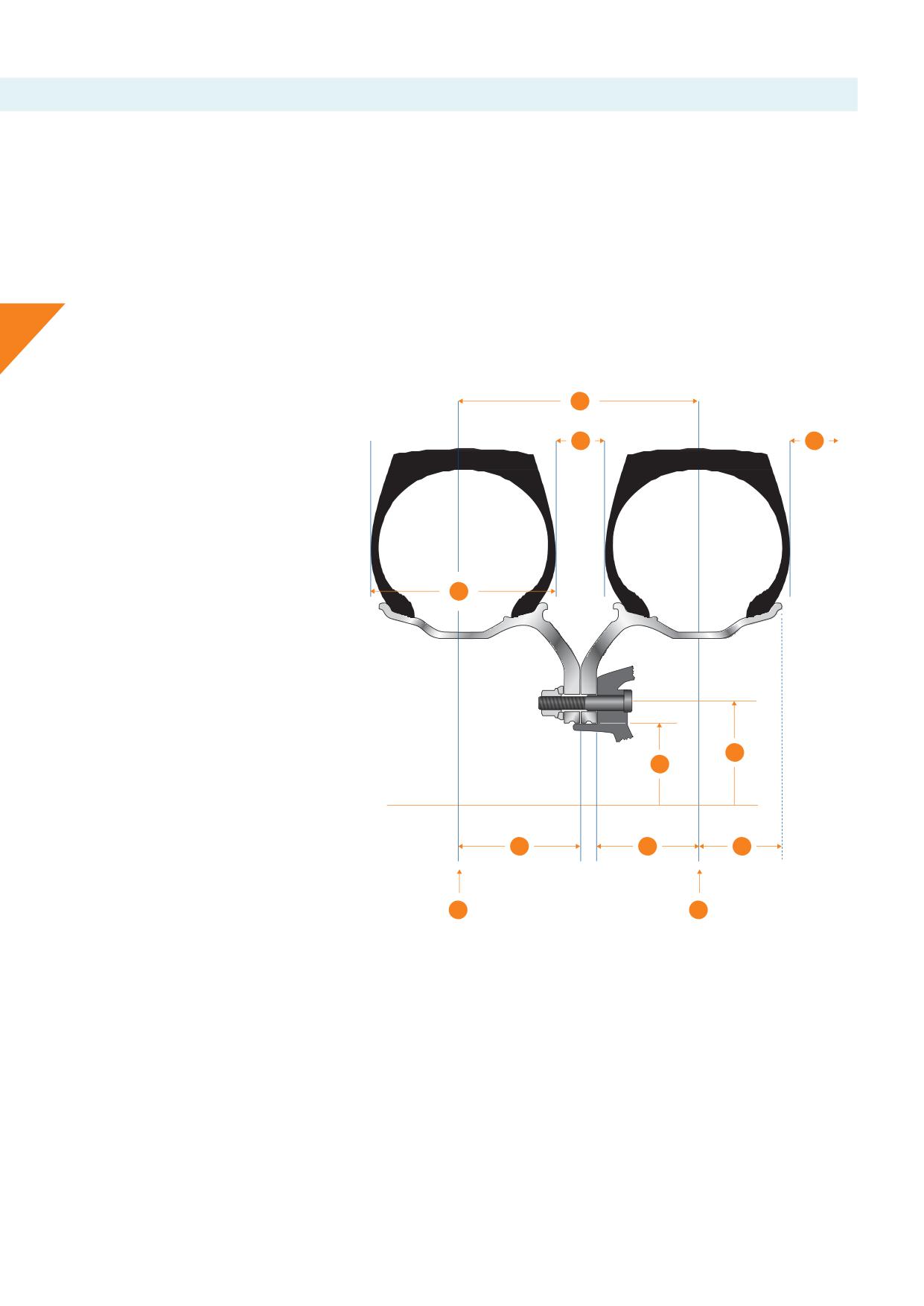
4.f.i. How to measure minimum dual spacing (for dual mounted wheels)
Minimum dual spacing measurement is determined by tyre
there will be enough minimum dual spacing. Wheel half dual
manufacturers and may be obtained from the tyre manufacturers’
spacing (outset) and off
(inset) is given for each wheel on the
handbooks. To determine if an assembly with dualled Alcoa®
Specifi
Sheet for Alcoa® Wheels.
Wheels have adequate minimum dual spacing for the selected
tyres, double the wheel half dual spacing or outset measurement of
Both off (inset) and half dual spacing (outset) of wheels are
the Alcoa® Wheels used.
measured from the mounting surface of the wheel to the centreline
of the rim. Maintaining correct tyre infl
and load ratings are
If the doubled half dual spacing or outset measurement is equal
essential to maintain enough minimum dual spacing.
4
to or greater than the tyre manufacturers’ recommendations,
1
2
3
1. Dual spacing
2. Tyre clearance
3. Vehicle clearance
4
4. Tyre section width
5. Hub bore
6. Bolt circle
7. Wheel outset, or half dual spacing
8. Wheel inset, or off
9. Back space
10. Tyre / rim centreline
6
5
7
8
9
10
10
Graphic 4-13
Alcoa® Wheels that can be mounted in dual position show the Half
DUAL MOUNTING
Dual Spacing (HDS) behind the wheel dimension (e.g., 22.5 x 9.00
- 176) in the roll stamp. This means the HDS is 176 measured in
DO NOT mount wheels with a diff
Half Dual Spacing (HDS),
millimetres.
unless vehicle or trailer axle manufacturer approved:
• Never mount wheels with a smaller Half Dual Spacing as there is
HMA: abbreviation of Halber Mittenabstand, commonly used on
a risk of tyres “kissing” in loaded condition. This will generate heat
German made wheels, stands for Half Dual Spacing (HDS).
and may cause tyres to blow out.
• Mounting wheels with a smaller Half Dual Spacing reduce the
track width. The stability and/or suspension components of the
vehicle may be compromised especially when loaded or curving.
14
4.f.ii. How to measure off
(for singlemountedwheels)
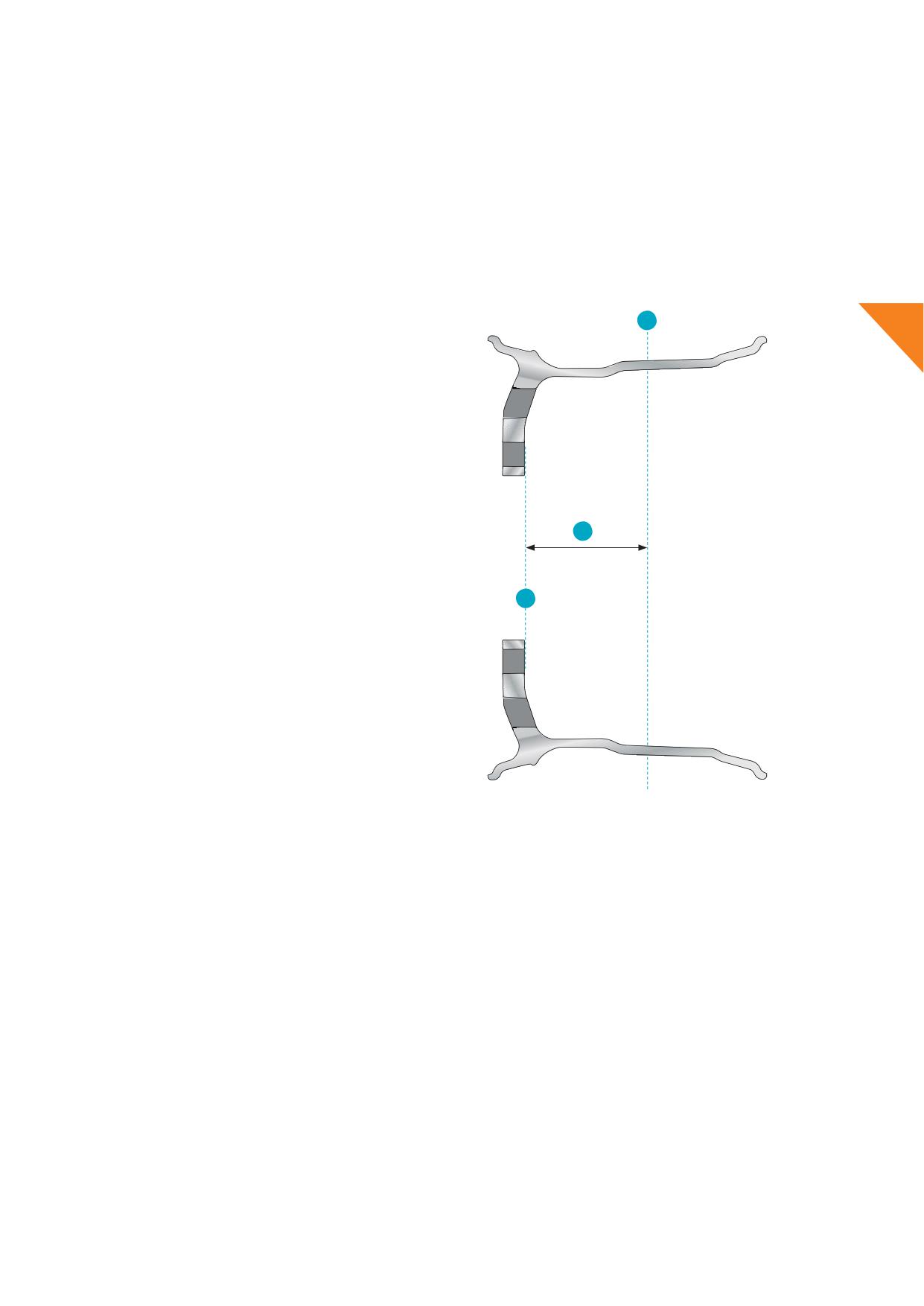
The off (or inset) measurement is determined by the vehicle or
Alcoa® Wheels that can be mounted in a single position only, show
(trailer) axle manufacturer and may be obtained from the vehicle or
the off
(or inset) after the wheel dimension
axle manufacturers’ handbooks. To determine if the wheel matches
(e.g., 22.5 x 11.75 - 120) in the roll stamp. This means the off
is
the recommended off (or inset) of a vehicle or trailer axle, consult
120 measured in millimetres.
the Specifi Sheet for Alcoa® Wheels.
ET: abbreviation of Einpresstiefe, commonly used on German made
wheels, stands for off
(or inset).
a Rim (tyre) centreline
4
a) Rim (tyre) centreline
b) Mounting fl
wheel disc
c
c) Off
or inset:
Off (mm)
distance rim centreline to mounting fl
measured in Millimetres
b
Mounting fl
Graphic 4-14
SINGLE MOUNTING
Off
/inset higher / lower
DO NOT mount wheels with a diff
off
(or inset), unless
• Alteration of the tyre / rim centreline will distribute loads
vehicle or trailer axle manufacturer approved: e.g., do not fi 22.5 x
diff
on the bearings. It may shorten the service life or
11.75 with off (or inset) 120 at axle where off
135 is
cause failure of bearings. It may generate heat to one or the
standard, or do not fi 22.5 x 11.75 with off
135 where off
120
other bearing, causing or igniting a fi
is standard.
• Geometry of the alignment of axles can be infl
causing
diff
manoeuvrability of the vehicle.
Off
/ inset higher
• Wheel or tyre may contact parts of brakes, steering, suspension
Off
/ inset lower
or chassis. This may cause a tyre blow out, damage to
• The wheel tyre assembly may exceed the allowed maximum
components with the risk of accidents causing injuries or death.
vehicle width voiding road and traffi regulations.
• The stability and/or suspension components of the vehicle may
be compromised especially when loaded or curving.
Note:
Off
(Inset) + wheel disc thickness = Half Dual Spacing (Outset). For reference consult Specifi
Sheet for Alcoa® Wheels or wheel data
specifi
sheets of other steel or alloy wheels if used.
15
4.g. Mixed application of Alcoa® Wheels
Changes to design and specifi
may result in a mix of Alcoa®
The combined load rate of the wheels must meet or exceed the
Wheels on one vehicle or one axle.
load rating of the axle. Consult the vehicle - or axle specifi
When mixing Alcoa® Wheels on one axle, wheel dimension, bolt
Trucks, buses, and trailers may have a variety of wheel load ratings
hole diameter and off for single mounting or half dual spacing
on one vehicle. It is mandatory to respect the vehicle or axle OEM’s
for dual mounting must match.
homologation as well as local and national road vehicle legislation.
4
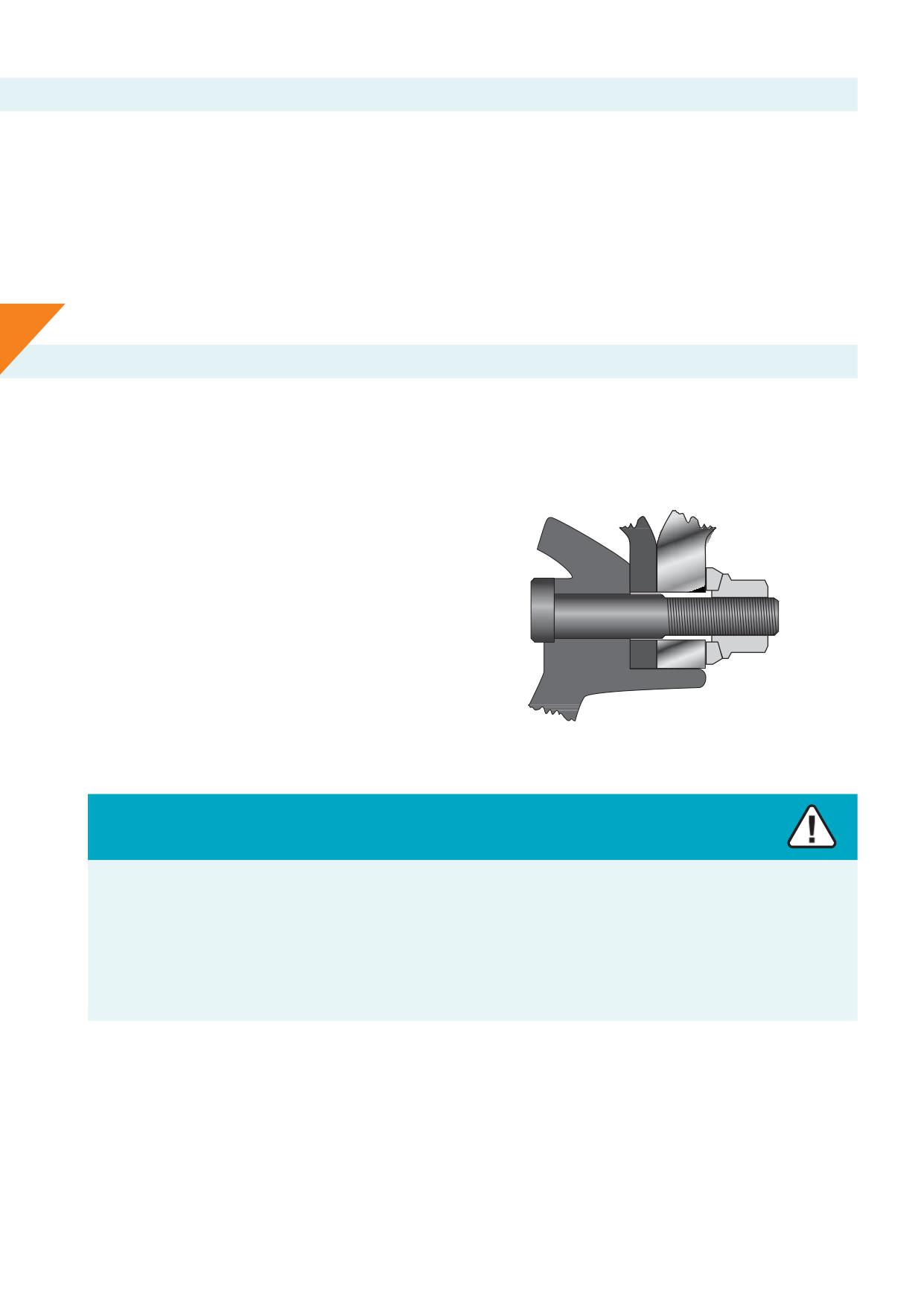
4.h. Mixed application of Alcoa® Wheels and steel wheels
Alcoa® Wheels can be operated in dual mounting with a steel wheel
IMPORTANT
mounted at the inner position. In the event a steel inner wheel is
Consult and respect the vehicle or axle OEM’s homologation as well
used, extreme care must be taken to properly mount both wheels
as local and national road vehicle legislation for the application of
to the hub.
mixed assemblies e.g. steel and aluminium wheels on one axle or
one vehicle.
The selection of correct hardware i.e., nuts, sleeved nuts and studs
are crucial to obtain a safe fi
as well as enough pilot tab
length on the hub to properly centre the outer aluminium wheel.
Both wheels, steel and Alcoa® Wheels, must match wheel size and
half dual spacing (outset), wheel load index, as well as being fi
with identical tyres and tread of the same depth.
A mixed dual fi
is subject to all recommendations and
guidelines that apply for safe and proper fi
of a steel dual
and aluminium dual fi
referring to manuals of steel wheel
® Wheels.
manufacturer and the Service Manual for Alcoa
Graphic 4-15
Warning
When mounting painted steel wheels with Alcoa® Wheels, in dual application, be cautious of excessive paint build-up on the steel
wheel.
Excessive paint (> 90 μm or 3.5 mil) can reduce the clamping force and allow the wheels to become loose, which can lead to serious
injury or death.
Follow the proper wheel installation and maintenance practices as described in this Section.
For more information about mounting and hardware for Alcoa® Wheels see Sections 10, 11 and 12
16
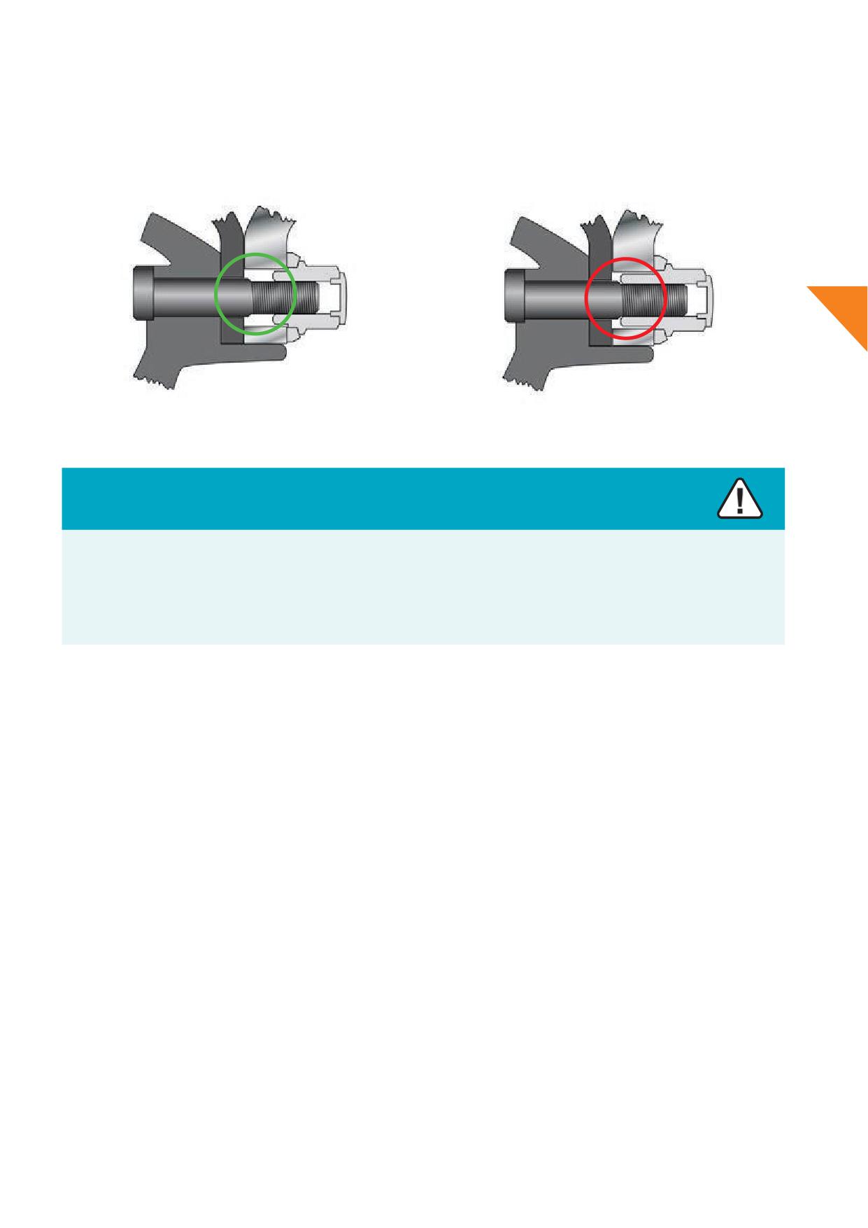
When mounting a steel wheel at the inside position and an aluminium wheel with sleeved nuts on the outer position it is important to
a) Determine the amount of threading engaged as set forth in Section 11.b.
b) Check if no ‘bottom out’ condition occurs when using long sleeved nuts as described in Section 11.b.ii.
4
✓
❌
Graphic 4-16
Graphic 4-17
Warning
The use of a wrong selection of wheels and hardware may result in improper fi
of wheels.
Improper mounting of wheels may lead to separation of wheels or loss of assemblies from the vehicle.
Separating wheels or loss of assemblies from the vehicle can lead to injuries or death.
For more information about mounting and hardware for Alcoa® Wheels see Sections 10, 11 and 12
HUB ENGAGEMENT
1. Stud standout and thread engagement (hardware)
A.
B.
For use with 2-piece fl
nuts and replacing (with longer) studs
For use with 2-piece sleeved nuts and maintaining the original studs
the minimal stud standout must be:
the minimal number of thread engagement between stud and nut
1x disc thickness steel wheel + 1x disc thickness Alcoa® Wheel +
must be:
height of nut + 3 mm for use with M22, M20 or M18 x 1.5 threads
(or 2 full threads in case of other type of threading such as BSF or
• 14 full turns for M22 x 1.5
(Metric, Volvo from 2005)
UNF).
• 13 full turns for M20 x 1.5
(Metric)
• 12 full turns for M18 x 1.5
(Metric)
Example: the disc thickness of 1x steel wheel and 1x Alcoa® Wheel
• 10 full turns for 7/8”-11 BSF
(Scania)
added with a regular 2-piece fl nut M22 x 1.5 must result in a
• 12 full turns for 7/8”-14 UNF
(Volvoupto2004)
minimal stud standout of 14 + 22 + 27 + 3 = 66 mm.
17
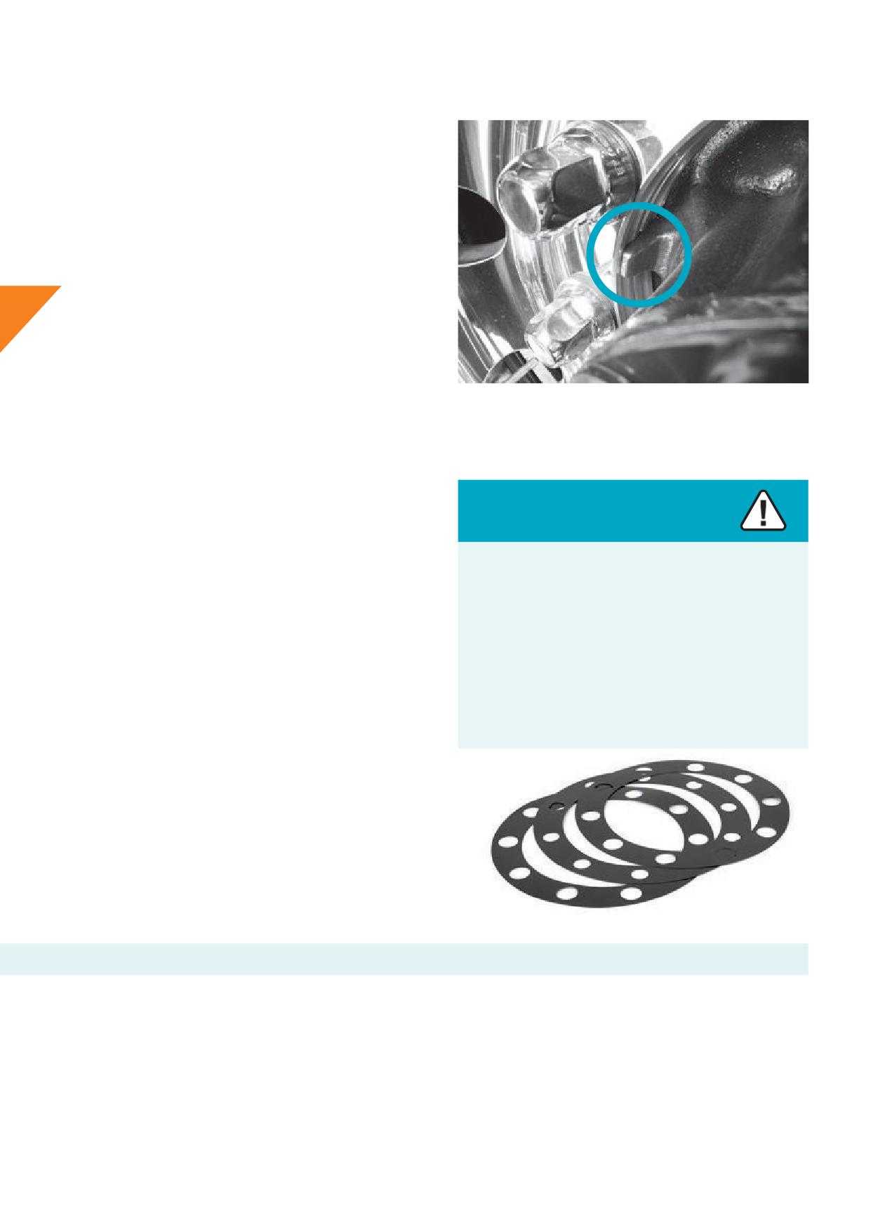
2. Piloting
Hubs designed for steel hub piloted wheels may not have enough
pilot length to locate dualled Alcoa® Wheels or with a wheel from
Alcoa® Wheels at the outer position and a steel wheel at the inner
position.
Pay close attention to the pilot tab length, particularly when
converting from dualled steel wheels to dualled aluminium wheels.
Measure the hub pilot tab to make sure the hub has a minimum
pilot tab length that allows no less than 5 mm for the outer wheel
to be centred, excluding the bevelled edges.
4
For example:
The horizontal part of the pilot tab should be at least 27 mm in
case theinner aluminium wheel’s disc thicknessis 22 mm. The
horizontal part of the pilot must be at least 19 mm for a mixed dual
in case theinner steel wheel’s disc thicknessis 14 mm.
Picture 4-18
3. Torque
When dualling steel wheels with Alcoa® Wheels, follow the vehicle
manufacturers’ recommendations regarding the proper torque and
use of thread lubricants to mount the wheel.
Caution
Steel wheels and forged aluminium wheels have diff
IMPORTANT
mechanical properties.
On occasion Alcoa® Wheels are dualled with steel wheels: it
Due to the diff
of mechanical properties, it may
is recommended that Discmates for Alcoa® Wheels or nylon
decrease the lifetime of one or the other.
protection gaskets are used to help prevent corrosion. See picture
4-19.
It is therefore recommended not to use mixed fi
in vocational, heavy load hauling fl
and/or off
In the event a steel wheel is used at the inner position, extreme
applications.
care must be taken to properly seat it to the hub or drum before
mounting the aluminium wheel at the outer position.
Selection of the correct hardware is required as providing adequate
thread length, to secure the outer aluminium dual wheel, is critical
to a safe assembly.
Howmet Wheel Systems recommends the use of sleeved nuts for
this purpose.
Picture 4-19
4.i.
Owner / in-service identifi
Some fl
wish to identify wheels as to OWNERSHIP and IN-SERVICE dates. Howmet Wheel Systems advises fl
and owners to stamp
wheels with the date they are put into service.
1. Use “Lo-Stress” stamps or equivalent.
2. Location of stamped areas on outside disc should be in space outward from a line between hand hole centres and a minimum of 2,5 cm
or 1 inch from the periphery of any hand hole.
3. Location of stamped identifi
on inside of wheel should be as close to the factory identifi
stamping as possible.
Note: Use of an impression stamp on Dura-Bright® surface treated wheels can aff
the appearance and performance of the Dura-Bright®
surface treatment at the stamp and in the stamp area.
18
5. Putting wheels in service
Warning
Warning
• Do not exceed the maximum wheel load indicated on the
• Some wheels are not designed for use on axles with disc
wheel.
brake systems.
• Exceedingthemaximumwheelloadmaycause the
• Attempting to mount or use wheels that are not designed
wheel / tyre to explode causing serious injury or death.
for axles with disc brake systems may cause wheel or
• Customer must compare vehicle and tyre load rating to
vehicle components to fail causing injuries or death.
maximum wheel load rating.
• For reference see part number on the wheel and
Specifi
Sheet for Alcoa® Wheels to ensure the wheel
can be used on disc brake operated axles / vehicles.
5
Before mounting the tyre, always perform a wheel fi
check to
ensure proper clearance from any obstructions. See ‘Wheel fi
check’ Section 5.d.
Warning
• Do not over-infl
the tyre / wheel assembly.
• Exceeding the maximum wheel load may cause the wheel / tyre to explode causing serious injury or death.
• Refer to tyre and wheel manufacturers’ recommendations for correct tyre pressure.
The maximum wheel load rating and infl
pressure is in the wheel's roll stamp. See Section 4.d.
Under no circumstances exceed cold infl
pressure listed by the tyre - and wheel manufacturer that is indicated on the tyre and wheel.
5.a. Putting wheels in service / hidden damage
Some forms of wheel damage can be hidden beneath the tyre, so
whenever a tyre is removed, thoroughly examine the complete
wheel. Remove all grease and road dirt. Use a wire brush or steel
wool to remove rubber from the bead seats.
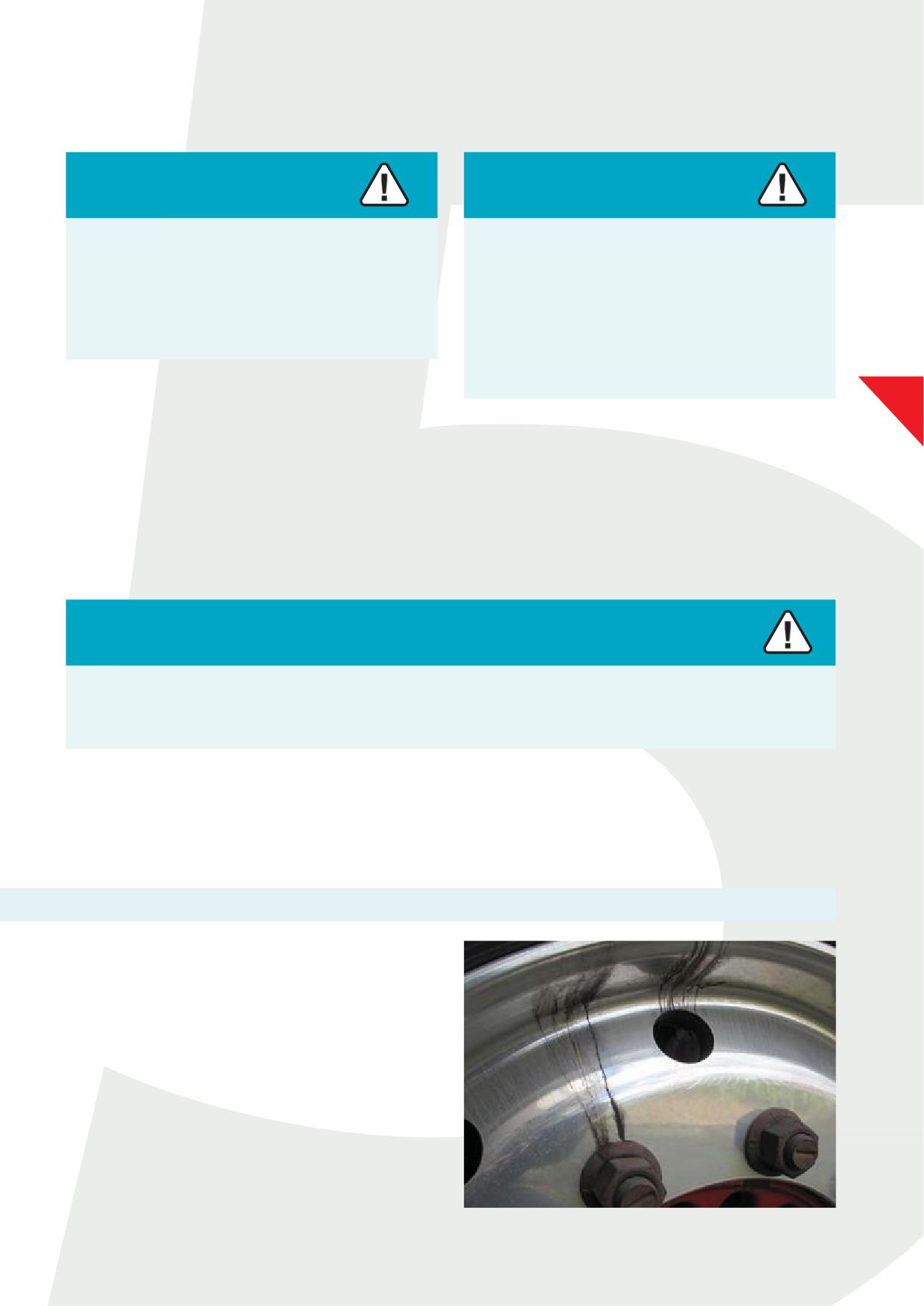
Check mounting holes for cracks, fretting, enlargement, and
elongation which can occur if the nuts are not kept tight. See
Section 12.a. Dirt streaks radiating from bolt and / or vent holes
may indicate loose nuts. See picture 5-1.
Picture 5-1
19
5.b. Putting wheels in service / wheel alteration
Howmet Wheel Systems does not approve any form of alteration
Wheel identifi
must be legible. Wheels should be taken out
to wheels except minor cosmetic buffi for appearance purposes.
of service if such identifi
is not legible or does not meet
Sanding and/or grinding is permitted to maintain the rim fl
requirements.
area of the wheel. See Section 13.g.
Do not alter wheels by welding, brazing or other heat application,
Warning
e.g., powder coating, in an attempt to repair or straighten a wheel.
Welding, brazing or otherwise heating any area of Alcoa®
Use of adapter plates or bead-locks are not approved on Alcoa®
Wheels will weaken the wheels.
Wheels.
Weakened or damaged wheels can lead to an explosive
Do not paint, powder coat or otherwise coat wheels in any way that
separation of tyres and wheels or wheel failure on the
may interfere with the mounting surfaces.
vehicle. Explosive separations of tyres and wheels or wheel
5
failure on the vehicle could cause serious injuries or death.
Any wheel that shows signs of alteration should be removed from
service and scrapped.
Never attempt to weld, braze, or heat any surface of Alcoa®
Wheels.
5.c. Putting wheels in service / mounting area and support
surface diameters
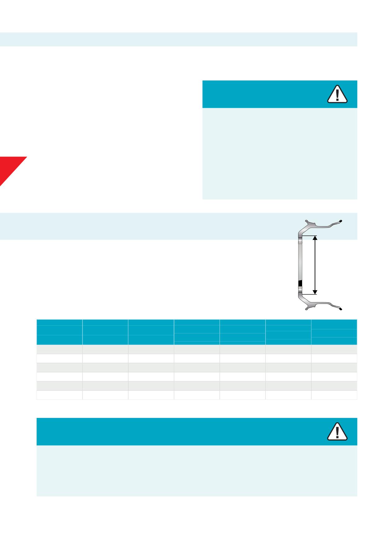
The support surface or backup of the hub should be fl to the diameter recommended (per ISO 4107, SAE
J694 and DIN 74361-3) below to properly accommodate the wheel disc area.
Backup
Graphic 5-2
Applicable to hub pilot mounting type Alcoa® Wheels:
Howmet
ISO 4107 Backup
SAE J694 Backup
DIN 74361-3
Bolt circle Ø mm
Nr of bolts
Thread size
recommended
Ø mm
Ø mm
Backup Ø mm
backup Ø mm
205
6
M18 x 1.5
250 - 251
245 - 250
250
245 - 251
245
6
M18 x 1.5
290 - 291
290
285 - 291
275
8
M20 x 1.5
320 - 321
315 - 320
320
315 - 321
275
8
M22 x 1.5
334 - 343
320
334 - 343
225
10
M22 x 1.5
270
273 - 279
335
10
M22 x 1.5
385 - 386
380 - 385
385
380 - 386
Chart 5-3
Warning
• Due to the limited contact area of star shape hubs, proper maintenance and cleaning of hub, wheel and mounting hardware is
important.
• As per recommendation from the Association of European Wheel Manufacturers, EUWA, wheels used on star shape hubs must be
checked for cracks on the inner and outer attachment face each 50.000 km.
• In case cracks are detected wheels must be removed from service immediately and permanently.
21
5.d. Putting wheels in service / before tyre mounting / WHEEL FITMENT CHECK
• Do not exceed maximum wheel load. Customer must compare
attempt to soften them for straightening or to repair other
OEM vehicle axle load ratings to maximum wheel load ratings.
damage. The special alloy used in these wheels is heat-treated,
• Refer to tyre manufacturers’ recommendations for proper tyre
and uncontrolled heating will weaken the wheel.
pressure.
• Do not weld the wheels for any reason.
• Before mounting the tyre, perform a wheel fi check to
• When tyres are removed, the entire wheel must be cleaned and
ensure proper clearance from any obstructions. See ‘Wheel
inspected. With a brush, remove any contamination from the
fi
check’.
wheel’s bead seats (portions of the wheel that support the tyre).
• Do not use a wheel that has been subjected to high pressure tyre
• Check the wheel’s fl
for wear with Alcoa® Wheels' Rim
and rim separation, run fl excessive heat, or other physical
Flange Wear Gauge. REMOVE SHARP EDGES ON THE RIM FLANGE
damage. A wheel subjected to any of these conditions may no
as explained in Section 13.g.iii.
longer have a correct dimension and contour to retain the tyre
• It is recommended that valves are replaced at every tyre change.
bead while under pressure.
See Section 5.e.iv.
• A cracked or damaged wheel may cause the wheel to fail or
• It is recommended to lubricate wheel fl
wheel bead seats
come off the vehicle while the vehicle is moving.
and tyre beads each time the tyre is mounted or demounted.
5
• Do not straighten the wheels. Do not heat the wheels in an
Wheel fi
check
1. Remove current wheel(s) from axle end(s) to perform fi
checkasnecessary.
2. Clean the mounting surface of the hub and mounting surface of the wheel to be installed (see Section 10.1. steps 1, 2 and 3).
3. Place the wheel for the fi
check over studs and hold the wheel on the hub and check for a fl
mount. The mounting surface of
the wheel (and balancing weights) must fi fl to the hub mounting surface. The backside of the wheel (and balancing weights) must
not rest against any obstructions, such as the brake calliper, steering and suspension components, rivets, etc.
4. Install three nuts and hand tighten. Rotate the wheel (and turn the steering column fully in both directions if checking the steer
position) to ensure clearance from any obstructions.
5. Repeat steps for each axle end as applicable.
5.e. Valves for Alcoa® Wheels
New Alcoa® Wheels come with valves fi
All valves and valve
If the P/N of a wheel and matching valve is not found contact
nuts are nickel plated and come with a metal dust cap that includes
Howmet Wheel Systems or an authorized distributor of Alcoa®
a seal for air tightness. Metal valve caps are recommended.
Wheels:
Valves used by Howmet Wheel Systems for Alcoa® Wheels are
standardized by ETRTO: the use of valves that do not meet
these specifi
or non-genuine valves may jeopardize the
roadworthiness of the vehicle or safety.
Consult the Specifi
Sheet for Alcoa® Wheels for the correct
and matching valve when ordering and replacing valves.
Original equipment valves and - replacement valves may be
obtained from an authorized distributor of Alcoa® Wheels
Note: Metal valve stem caps are required per DOT (Department of
Transportation) instead of plastic.
20
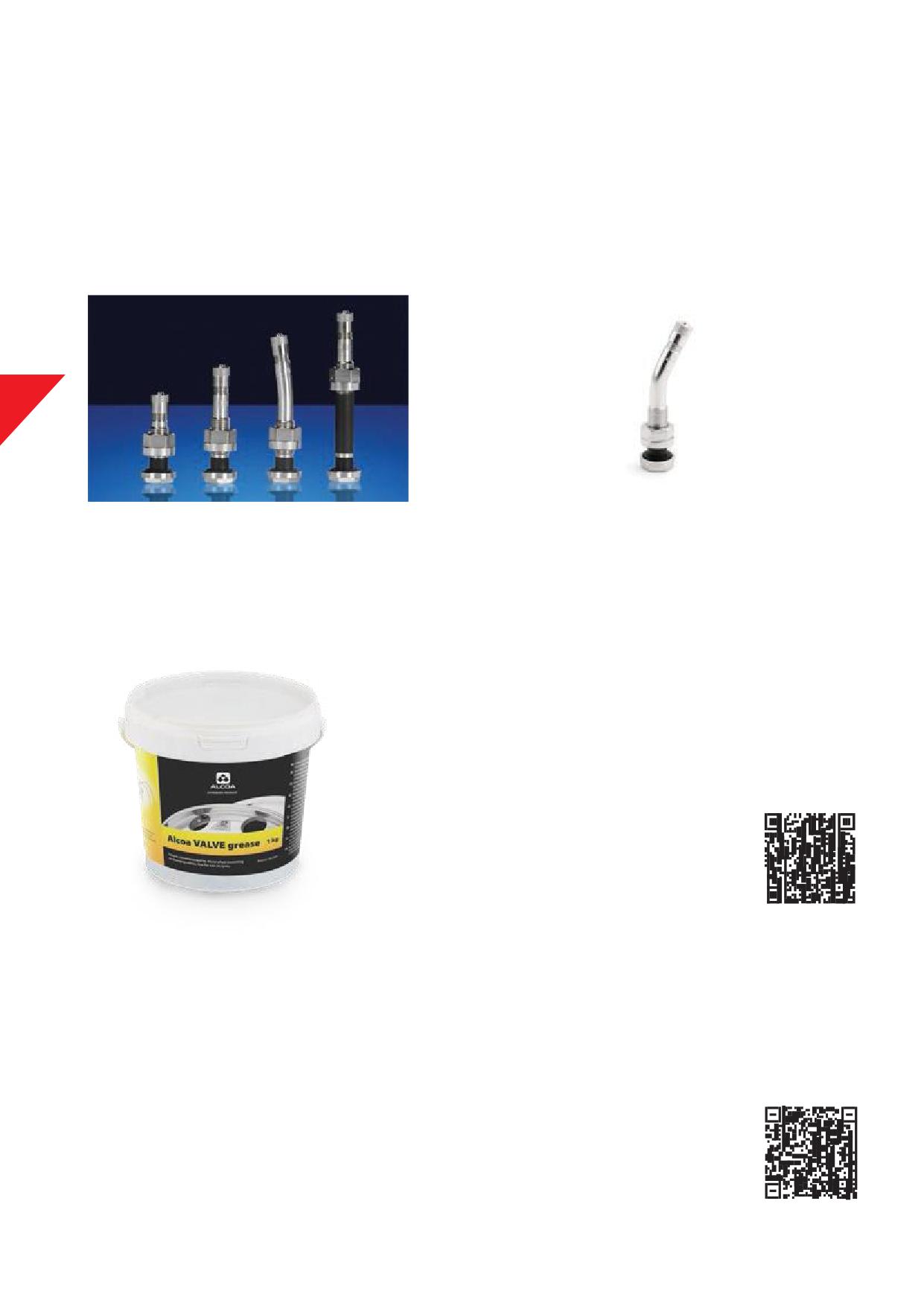
5.e.i. Valves with black / orange T-shape grommet with 1-piece nut
40MS-00N, 54MS-00N, 60MS-00N (not pictured), 70MS-07N2,
It also reduces the chance of damaging the valve hole when
83MS-00N original equipment valves (Picture 5-4)
applying too much torque to the valve nut.
70MS-27N, 70MS-45N (not pictured), 70MS-60N (not pictured)
Thesevalvesdonotnecessarily needlubricationorgreasingwhen
replacement valves (Picture 5-5)
checking or replacing.
Thesevalves come with a 1-piecenutwith enlarged contact surface
Lubrication or greasing helps to prevent corrosion and eases the
that evenly distributes the forces in the valve hole area.
insertion of the valve when mounting. See VALVEgrease.
5
Picture 5-4
Picture 5-5
VALVE grease
When mounting or replacing valves use VALVEgrease for
Alcoa® Wheels or a non-water and non-metal-based lubricant.
DO NOT use tyre mounting paste when mounting or replacing
metal valves.
VALVEgrease for Alcoa® Wheels is available from authorized
distributors of Alcoa® Wheels.
Picture 5-6
Check the Specifi
Sheet for Alcoa® Wheels for the correct and matching valve. If the P/N is not found contact
Howmet Wheel Systems or an authorized distributor of Alcoa® Wheels.
See the Specifi
Sheet for Alcoa® Wheels:
Original equipment valves and - replacement valves may be obtained from an authorized distributor of Alcoa® Wheels.
22
Caution
Valves with a T-shape grommet may get squeezed or folded upon installing.
As a result, the T-shape grommet may get cut or torn causing air loss.
Carefully insert the valve to avoid the T-shape grommet from being squeezed or folded. Lubrication or greasing helps to ease the
insertion of the valve when mounting.
5.e.ii. Valve nuts and torque
Valves for Alcoa® Wheels have 14, 16 mm or 5/8” hex nuts. The recommended torque is 12 to 15 Nm (9 to 11 Ft-Lb).
5
5.e.iii. Valves, general recommendations
DO’s
DON’Ts
1. It is recommended that valves be replaced at every tyre change
1. Do not fi valves for steel wheels. Valves for steel wheels may
with an original / genuine valve for Alcoa® Wheels which are
have diff
diameters, diff
bends (angles) and/or
available from authorised Alcoa® Wheel distributors.
insuffi
thread length.
2. Before mounting the new valve, check if the valve corresponds
2. Do not use brass valves without plating. Aluminium and brass
with the wheel. Use the Specifi
Sheet for Alcoa® Wheels
cause accelerated galvanic corrosion. This corrosion may result
for reference.
in leakage.
3. To avoid loss of air by improper fi
Alcoa® Wheels should
3. Do not bend the standard valve to another shape.
be fi
with chrome- or nickel-plated valves that meet the
4. Do not use rubber O-rings or grommets.
standards and that are specially designed for Alcoa® Wheels.
5. Do not use tyre mounting paste when installing or replacing
4. When replacing O-rings or grommets, use silicone, Viton® or
valves.
EPDM O-rings or grommets.
6. Do not infl
the tyre with air coming from an air system, using
5. When replacing valve stems, it is recommended that the O-ring
lubrication for pneumatic power tools.
or grommet be lubricated with VALVEgrease for Alcoa® Wheels
7. Do not use liquid tyre balancers or sealants. These products
or with a non-water non-metal-based lubricant.
may cause extremely rapid corrosion of the valve hole area,
6. Use only dry air for tyre infl
Be sure that the in-line air
bead seats and drop centre. Cracks may be initiated with air
dryer is maintained properly. The use of moisture traps in the
loss as a result.
air compressor feed line is recommended.
8. Balancing with powder or granulates is not recommended.
7. Valve dust caps with an air seal are recommended.
These products may cause malfunctioning of the valve core
with air loss as a result.
9. Do not use metal or brass valve extensions without a solid
support. Unsupported metal extensions accelerate fatigue to
the valve base or valve hole area due to centrifugal forces. As a
result, cracks may occur in the valve base and/or the valve hole
areats, causing air loss.
10. Do not use extension tubes without a proper clamping
installation attached to the outer wheel. Loose extension tubes
may cause damage to the wheel and tube with air loss as a
result.
2
3
5.e.iv. Replacing valves
The best occasion to check the valve is when tyres are replaced. It
is recommended to fi a new valve every time when a new tyre is
mounted.
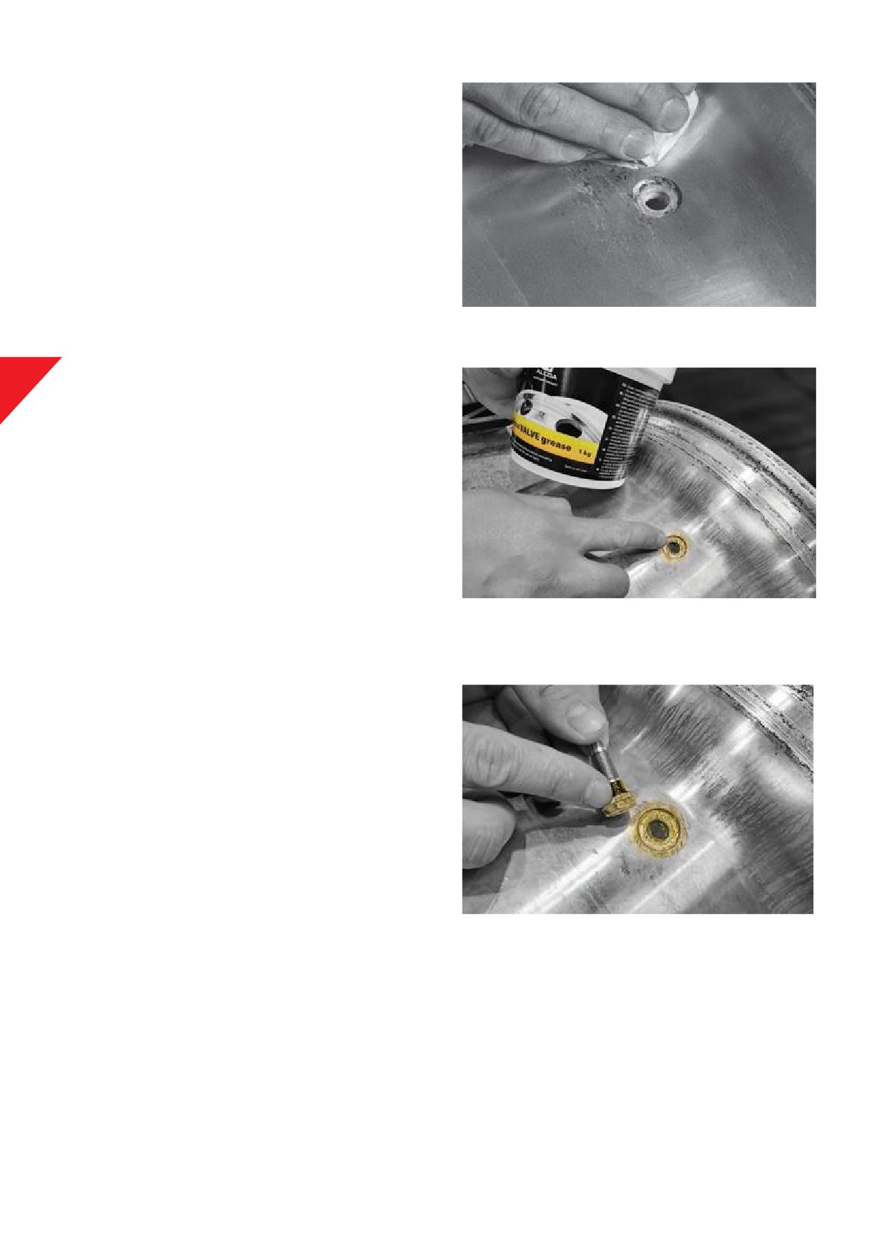
Clean the valve seat and valve hole thoroughly after removal of the
valve. Remove all dirt, grease, and oxidation. Make sure all contact
areas are dry. Check for sharp edges or burrs. See picture 5-7.
Avoid using sharp tools and/or excessive force that could cause
scratches or dents in the surface. Uneven or damaged surfaces can
lead to leakage. Fine sandpaper, steel wool, a soft wire brush or
Picture 5-7
Bristle discs for Alcoa® Wheels will help to clean the valve hole area
without harming the surface.
5
Apply a layer of VALVEgrease for Alcoa® Wheels or non-water
non-metal-based lubricant in the valve hole and the outer and inner
side wheel surface, up to 2,5 centimetres or 1 inch in diameter
around the valve hole. See picture 5-8.
Before installing the valve, apply a thin coat of VALVEgrease for
Alcoa® Wheels or non-water non-metal-based lubricant at the base
of the valve and the O-ring or T-shape grommet is located. See
picture 5-9.
Do not use any other lubricants that are water-based or lubricants
that contain metals.
Picture 5-8
Upon installing hold the valve in its position and check the
alignment to be able to mount a valve extension for dual mounting
applications. This applies to valves with a bend or angle.
Note:
Upon installing valves with T-shape grommet, insert the valve
carefully to avoid the T-shape grommet from being squeezed
or folded. As a result, the T-shape grommet may get cut or torn
causing air loss.
Install the valve with care and do not over torque: the
recommended torque is 12 to 15 Nm (9 to 11 Ft-Lb).
IMPORTANT
Refer to the vehicle OEM for installing or replacement of valves
with tyre pressure monitoring system (TPMS) modules. For more
Picture 5-9
information about valves with TPMS modules, consult Section 5.e.v.
24
5.e.v. TPMS valves and modules
Vehicle OEM may off a Tyre Pressure Monitoring System (TPMS)
Application Guidelines for Alcoa® Wheels, with TPMS for individual
on vehicles, replacing the Alcoa® Wheels valve. A TPMS is an
vehicle OEM, are available from Howmet Wheel Systems.
electronic system designed to monitor the air pressure inside the
tyres of vehicles.
Valves used for inboard versions i.e., the TPMS module is in the
Caution
air chamber, use special valves designed by / for the vehicle
manufacturer. These TPMS valves are available through the
vehicle manufacturer organization and authorized Alcoa®
When de- or mounting tyres avoid contact between tyre
Wheels distributors.
beads and inboard TPMS module to prevent from damaging
tyre and/or inboard TPMS module.
Outboard versions may be fi
or connected using the Alcoa®
Wheels valve as a base. Care needs to be taken for correct fi
A damaged TPMS module may cause malfunctioning of the
i.e., matching threading, correct torque, enough stabilizing or
system or cause a tyre blow-out with serious injury or death
5
support to avoid additional stresses on the valve or valve bore.
as a result.
Unless the vehicle / axle OEM recommends otherwise: apply a layer
Consult the vehicle OEM network for proper installation,
of VALVEgrease for Alcoa® Wheels or non-water non-metal-based
parts and tools required.
lubricant in the valve hole and the outer and inner side wheel
surface, up to 2,5 centimetres or 1 inch in diameter around the
valve hole.
5.f.
Valve extensions
Authorized distributors of Alcoa® Wheels off diff
valve
extensions. A quality extension of 150 mm (6inches) will enable
tyre pressure checks and adjustment of the infl
of the inner
tyre of a dual fi
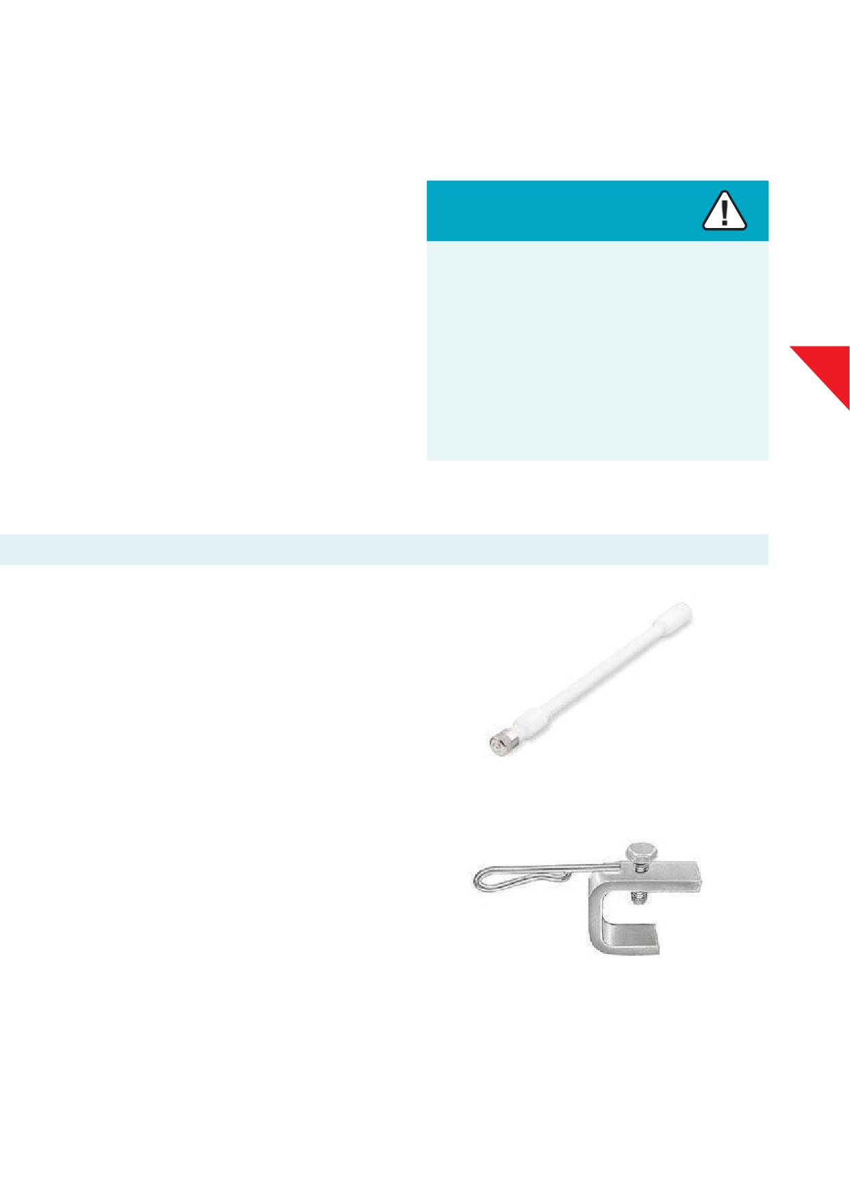
A valve stem stabilizer must be used if metal valve extensions are
used.
The mass of metal valve extensions and rotation may cause forces
that can lead to cracks in the valve hole area of the wheel or the
valve stem.
Picture 5-10
POM plastic valve stem extensions (Picture 5-10) are recommended
and can be obtained from an authorized distributor of Alcoa®
Wheels.
When using extension tubes, attach the tube with a proper
clamping bracket (Picture 5-11) attached to a vent hole of the outer
wheel.
ATTENTION: Use of stabilizers or clamping brackets on Dura-Bright®
surface treated wheels can aff
the appearance and performance
of the Dura-Bright® surface treatment at the area of contact with
Picture 5-11
the stabilizer or clamping bracket.
Valves availability
Only use original valves for Alcoa® Wheels. These valves are specially made to fi Alcoa® Wheels and are not available in the aftermarket /
replacement market. Howmet Wheel Systems off
all listed valves for Alcoa® Wheels through its distributor network. For more info, please
contact an authorized distributor of Alcoa® Wheels or Howmet Wheel Systems.
25
6. Before mounting tubeless tyres
6.a. Safety and compliance
Tyres and wheels that are not properly fi
or maintained may
not be safe.
Warning
Always comply with the procedures in the tyre and wheel
manufacturers’ catalogues, instruction manuals or other industry
Tyre and wheel servicing can be dangerous.
and government instructional materials.
Failure to read and comply with all of these procedures and
Follow the proper tyre fi
and maintenance practices as
practices may result in serious injury or death.
contained in the tyre manufacturers’ manuals and Sections
6.b. to 7.c. of this manual.
Tyre and wheel servicing must only be performed by trained
personnel using proper procedures and tools.
Always wear adequate protective eyewear (or face shield),
protective foot and hand wear and hearing protection while
6
servicing tyres and wheels to avoid injury.
6.b. Tools and machines
Always:
• Use those tools recommended by the tyre or wheel
Warning
manufacturer
• Keep tools clean and inspect them frequently
If you do not know how to use tyre servicing tools: Stop!
Never:
Failure to follow proper procedures can result in serious
• Use a tyre tool for anything except for demounting and mounting
injury or death.
tyres
• Use an extension bar with tyre irons
Tyre servicing must only be performed by trained
• Use tools with a loose or cracked handle
personnel.
• Use bent, cracked, chipped, dented, or mushroomed tools
• Alter or apply heat to any service tool
Typical tyre service tools:
Not all tyre mounting / demounting machines work the same. Be
• Bead unseating tools
sure to read the operating or instruction manual for your machine
• Tubeless tyre iron set
before attempting to mount or demount tyres.
• Clip-on air chuck / in-line gauge with enough hose length
• Safety restraint / tyre cage
2
6
6.c. Inspection
1. Do not gouge or nick the wheel during inspection.
Note:
2. Do not use a wheel that has been exposed to excessive heat
• For inspection of tyres refer to the manufacturers’
from tyre fi
brake fi
severe brake system drags or
documentation.
seizures or other causes. See Section 13.d. Heat damage.
• For inspection of Alcoa® Wheels refer to Sections 13 of this
3. Do not use a damaged tyre or damaged wheel. Inspect them
manual.
carefully before mounting. See Section 13 Wheels in service.
4. Do not use a severely corroded wheel. See Sections 13.i. and
13.j.
5. REMOVE SHARP EDGES ON THE RIM FLANGE. See Section 13.g.
Rim fl
wear.
Warning
Warning
Use of inner tubes in tubeless wheels will hide slow leaks.
Mounting damaged tyres or wheels can lead to an explosive
Slow leaks may indicate cracked or damaged wheels which
separation of tyres and wheels.
6
lead to wheel failures. See Section 13.h.iv.
Explosive separations of tyres from wheels can cause serious
Wheel failures can cause accidents which may result in
injury or death.
serious injury or death.
Inspect tyres and wheels for damage before mounting the
Never use an inner tube on tubeless Alcoa®
Wheels.
tyres. If damage is found, immediately and permanently
Immediately and permanently remove cracked or damaged
remove damagedtyres or wheels from service.
wheels from service and scrap.
6.d. Matching of tyre, wheel, and axle load
1. Use only the appropriate tyre size, matching the rim
width, according to ETRTO and/or tyre manufacturers’
recommendations. Refer to the OEM vehicle documentation
Warning
and tyre manufacturers’ documentation. See Section 4.e. Tables:
matching tyre to rim.
Never assemble a tyre and wheel unless you have positively
2. Alcoa® Wheels for commercial vehicle tubeless tyres have a 15°
identifi
and correctly matched the tyre and wheel
bead seat angle and accommodate tubeless tyres. Never use
diameter.
tube type tyres on Alcoa® Wheels.
3. Do not exceed maximum wheel load. Customer must compare
If an attempt is made to seat the tyre bead by infl
on
OEM vehicle axle load ratings to maximum wheel load rating.
a mismatched wheel, the tyre bead will break, or tyre will
4. Before mounting the tyre, perform a wheel fi
check at the
separate from the rim with explosive force and may result in
vehicle to ensure proper clearance from any obstructions.
serious injury or death.
See ‘Wheel fi
check’ Section 5.d.
5. Refer to tyre manufacturers’ recommendations for proper tyre
Before assembling a tyre and a wheel be sure to identify if
pressures. The recommended tyre pressure may not exceed the
the tyre - and the wheel diameter match.
maximum infl
pressure of the wheel.
Mismatching tyre and wheel diameters are dangerous. A
mismatched tyre and wheel assembly may separate and can result
in serious injury or death. This warning applies to 15” and 15.5”, 16”
and 16.5”, 17” and 17.5”, 19” and 19.5”, 22” and 22.5”, 24” and 24.5”
tyre and wheel assemblies as well as other sized assemblies.
2
7
6.e. Valve
1. Check if the matching valve is mounted in the right way with proper torque. See Section 5.e. of this manual
(Valves for Alcoa® Wheels).
2. When match-mounting tyres on Alcoa® Wheels, locate the valve adjacent to the low point mark on the tyre.
3. For matching valves and additional information see Specifi
Sheet for Alcoa® Wheels, column ‘Valves’
6.f.
Lubricant
1. When selecting a lubricant, it is preferable to use a
non-water-based lubricant for tyre mounting that also does not
contain metals and is pH neutral.
Warning
2. Alternatively use a non-fl
vegetable or soap-based
rubber lubricant, always pH neutral, on the tyre beads and rim
Never use starter fl
propane, ether, gasoline, or other
surfaces.
fl
materials and/or accelerants to lubricate the
beads of a tyre or bead seats of the rim.
6
Lubricating bead seats and drop well:
• Preferably use a non-water-based lubricant for tyre mounting
This practice can cause the explosive separation of the tyre
that does not contain metals and is pH neutral.
/ the wheel during servicing or during road use, which may
• Water-based lubricants accelerate corrosion on the bead seats
result in serious injury or death.
and drop well surface.
• Corroded bead seats may not be airtight. Corrosion in the bead
Use appropriate and designated lubricants for lubrication of
seats may initiate cracks with air loss as a result.
the beads of a tyre and/or bead seats of the rim.
• Corrosion at the drop well may initiate cracks with air loss as a
result.
Lubricating valve and valve hole area:
• Use VALVEgrease for Alcoa® Wheels or a non-water-based
lubricant that does not contain metals and is pH neutral.
• Water-based and / or metal-based lubricants may cause and
accelerate corrosion at the valve and valve hole area.
• Corrosion at the valve and valve hole area may result in loosing
air tightness of the valve O-ring or grommet.
• Corrosion may initiate a crack in the valve hole area with air loss
as a result.
2
8
6.g. Mounting tyres on symmetrical and non-symmetrical drop well wheels
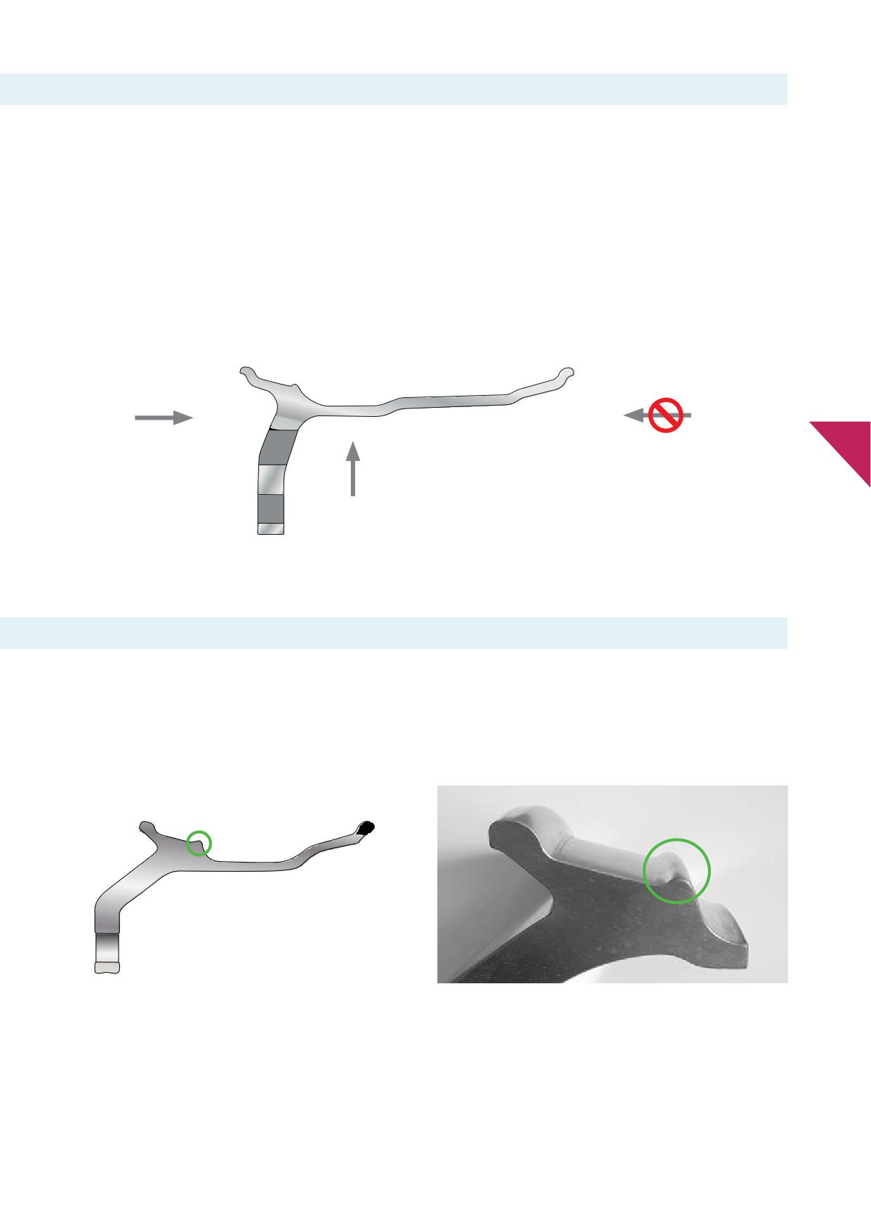
Alcoa® Wheels may contain a symmetrical drop well with a narrow
other wheel designs feature an increased under well diameter and
ledge on both sides of the rim. This feature allows mounting of the
also have a non-symmetrical sloping rim profi which provides
tyre from either side of the wheel.
additional brake clearance.
However, some Alcoa® Wheels are non-symmetrical and contain
In order to minimize the possibility of tyre bead damage, mounting
a non-symmetrical drop well or narrow ledge on only one side of
and demounting of the tyre should be performed only from the
the wheel (see graphic 6-1). Reduced well wheels as well as some
narrow ledge side of the wheel.
Graphic 6-1
mount from this side
do not mount from this side
6
Tyres should be mounted/demounted only
across the disc side of the wheel.
6.h. Symmetrical drop well wheels with safety hump
Alcoa® Wheels often contain a safety hump on one bead seat of
In case of a symmetrical drop well mounting and demounting of
the rim. This design feature is requested by European vehicle
the tyre may be performed from the side of the wheel without the
manufacturers. It prevents the tyre bead from slipping into the
safety hump by preference.
drop well when tyres are operated at low or defl
tyre pressure
when curving.
safety hump
safety hump
Graphic 6-2
Graphic 6-3
29
7. Mounting tubeless tyres on
Alcoa® Wheels
7.a. Mounting tyre to rim
IMPORTANT
• Not all tyre mounting / demounting machines work the same.
Be sure to read the operating or instruction manual for your
machine brand before attempting to mount or demount tyres.
Follow your machine brand operating and instruction manual.
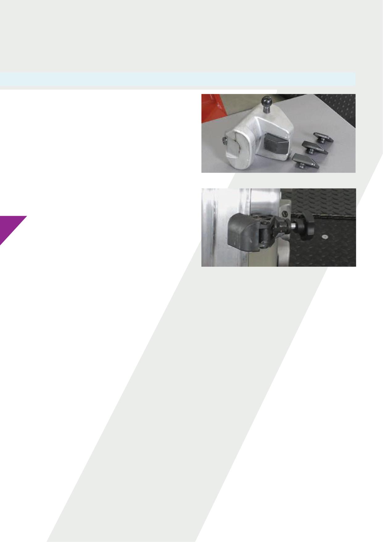
• Use special fi
for aluminium wheels on the machine’s
chuck for clamping aluminium wheels. See for example picture
7-1 .
• Use a plastic or nylon mounting aid for mounting tyres on Alcoa®
Wheels. See for example picture 7-2.
Picture 7-1
Before mounting:
• Inspect the tyre for damage. Refer to tyre manufacturers’
documentation and guidelines.
• Clean the beads of the tyre. Be sure the beads and inside of the
tyre are dry before it is mounted.
7
• Do not exceed the maximum wheel load. Compare vehicle/ axle
load rating to maximum wheel load rating.
• Perform a wheel fi
check on the vehicle/axle to ensure
proper clearance from any obstructions.
• See ‘Wheel fi
check’ Section 5.d.
Picture 7-2
1. Do not gouge or nick the wheel.
Note: Additional care should be used when mounting Dura-Bright® surface treated wheels since minor nicks and scratches cannot be
polished out. See Section 14.b. for specifi cautions, care and maintenance procedures.
2. Inspect the wheel for damage. Do not use a damaged or severely corroded wheel. See Section 13. REMOVE SHARP EDGES ON THE RIM
FLANGE. See Section 13.g.
3. Identify the short side of the drop centre well. Single-piece tubeless rims and wheels must be mounted from the short side of the drop
centre well. I.e. tyre beads should be mounted over the rim fl
closest to the wheel well.
Note: Aluminium wheels typically have symmetrical drop centres so tyres can be mounted from either side. However, certain aluminium
wheels, have a non-symmetrical drop centre, or the short side of the drop centre well is located on the disc side. See Section 6.g.
4. Before mounting a new tyre, clean the bead seats thoroughly until a smooth and clean surface is reached. For reference see Section 10,
pictures 10-2, 10-3 and 10-4.
Note: Avoid using strong abrasive tools and/or excessive force that could cause dents in the surface. Uneven or damaged surfaces can
lead to leakage.
Note: Frequent changing of tyres in undesirable conditions, use of water-based lubricants or lubricants with a pH value other than
neutral for tyre fi
as well as neglecting to clean the surface of the bead seat, can lead to loss of air caused by corrosion, oxidization
of the aluminium and dirt build up.
Note: Certain types of rubber can “fuse” to the bead seat of the wheel. If this rubber and other residues are not removed before the
fi
of a new tyre the uneven surface can lead to loss of air.
After cleaning the bead seats, insert a wire down the valve stem to ensure it is not blocked.
5. Position the wheel on the machine. Lubricate wheel bead seats and tyre beads using an approvedlubricant. Tyre beads should be
mounted starting over the rim fl
closest to the wheel well.
Note: When match-mounting tyres on Alcoa® Wheels locate the valve stem adjacent to the low point mark on the tyre.
30
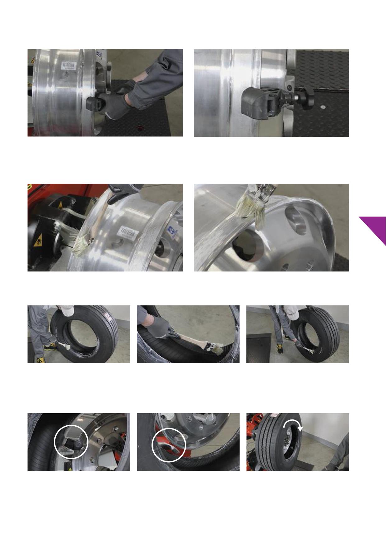
6. Attach the mounting aid to the front rim fl
Picture 7-3
Picture 7-4
7. Be sure the bead seats, and drop centre are dry before applying tyre mounting lubricant. Generously lubricate wheel rim fl
bead
seats and drop well using an approved lubricant (see Section 6.f.) immediately before mounting the tyre while rotating at the machine.
Position the mounting aid at 10 o’clock position.
7
Picture 7-5
Picture 7-6
8. Lubricate both tyre beads and inside of the second bead just before mounting the tyre. Avoid letting the lubricant to dry.
Picture 7-7
Picture 7-8
Picture 7-9
9. Position the tyre on the wheel with the rear bead positioned on the mounting aid. Position the “tool arm” (picture 7-11) in level with the
rim fl
(without contacting it) making sure the “tool arm” engages the bead completely. Rotate the wheel clockwise until the rear
bead is completely mounted and seated in the drop well. Remove the mounting aid.
Picture 7-10
Picture 7-11
Picture 7-12
32
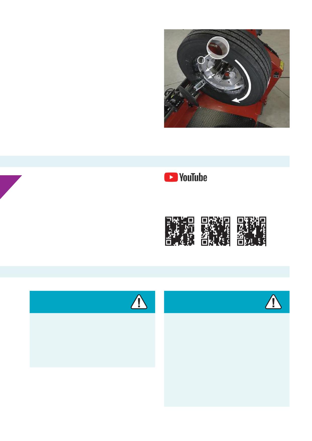
10. Position the “tool arm” to the front in level with the rim fl
(without contacting it) making sure the “tool arm” engages the
bead completely. Position the valve location on top. Attach
the mounting aid a little above the “tool arm”, below the valve
location. Turn the wheel clockwise until the second bead is
properly mounted. Detach the mounting aid and disengage the
“tool arm”.
IMPORTANT
Do not cut or damage the bead of the tyre.
Picture 7-13
7.b. Manual operation mounting and demounting tubeless tyres
Please refer to instructions and guidelines of suppliers and/or
7
manufacturers of tools used for manual de- and mounting of
tubeless tyres.
See Alcoa® Wheels’ YouTube channel (from left to right):
Mounting / demounting tyres, 22.5 x 9.00
Note:
Mounting / demounting tyres, 22.5 x 11.75 off
0
When hand mounting and demounting tyres, placing aluminium
Mounting / demounting tyres, 22.5 x 11.75 off
120
wheels on a clean wooden fl
or rubber mat is recommended.
Additional care should be used when mounting and demounting
Dura-Bright® surface treated wheels since minor nicks and
scratches cannot be polished out. See Section 14.b.
7.c. Infl
and bead seating check
Warning
Warning
A pressurized tyre/wheel assembly can explode and separate
Never use a volatile or fl
material, such as ether or
violently.
gasoline, as an aid to seating the tyre beads on the wheel.
Such use can lead to an uncontrolled pressure build-up in
This violent separation can cause serious injury or death.
the tyre and may result in an explosion.
Always contain the tyre/wheel assemblyin an approved
Explosive separation of the tyre from the wheel can occur
infl
cage duringinfl
while seating beads in this manner, while adding pressure
to the tyre on or off the vehicle, or later, on the road. Loss of
vehicle control can result, which can cause serious injury or
death.
Only use approved mechanical or pneumatic bead seating
devices.
31
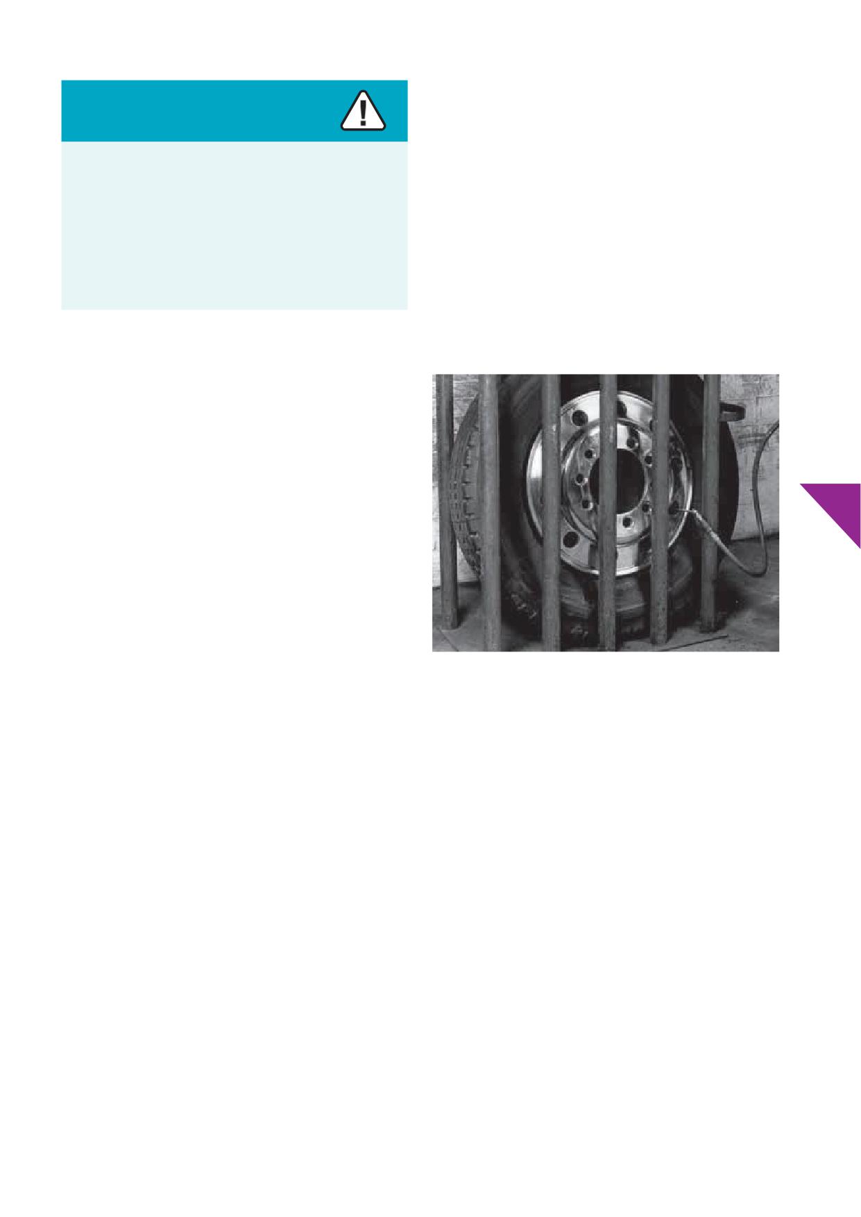
NEVERre-infl any tyre that has been operated in a run-fl
or underinfl
condition i.e., operated at 80% or less of the
Warning
recommended operating pressure. Demount, inspect, and match
all tyre and rim components before re-infl
in a safety cage.
An infl
tyre and wheel assembly contains enough air
If an emergency puncture repair infl
gaswasusedona
pressure to cause an explosive separation.
tubeless tyre, defl
and re-infl
the tyre several times to remove
potentially explosive propellant before servicing the tyre.
Unsafe handling or failure to follow approved mounting and
demounting procedures can lead to serious injury or death.
Study, understand and follow the procedures contained in
this manual to ensure your safety.
Note:
Picture 7-14 is an example of one type of a restraining device or tyre
cage. Manufacturers recommend that approved restraining devices
or tyre cages be free standing and located away from any vertical
fl or solid surface. The restraining device or tyre cage should not
be bolted to the fl
7
1. Before infl
any tyre rim/wheel assembly, be sure to read,
understand and comply with ALL WARNINGS.
2. Use only dry air for tyre infl
Be sure that the in-line
air dryer is maintained properly. The use of moisture traps
in the air compressor feed line is recommended.
3.
After mounting the tyre on the wheel, if needed use a
compressed air tank with a quick release valve to seat the
beads. Do not exceed 20 psi / 140 kPa / 1.4 bar before placing
the assemblyin an approved restraining device or tyre cage.
4.
Infl
the tyre, with the valve core removed, using a clip-on air
Picture 7-14
chuck with an in-line valve or pressure regulator and a suffi
length of hose. Infl
the assembly to 20 psi / 140 kPa / 1.4 bar.
6. Place tyre/wheel assembly inside an approved restraining
device or tyre cage after the tyre beads are seated. See picture
IMPORTANT
7.14.
Look for distortions, undulations, or other irregularities in
7. Continue to infl
the tyre to its recommended infl
the tyre sidewalls. Pay attention to any popping or snapping
pressure. Refer to tyre manufacturers’ recommendations for
sounds. If ANY of these conditions are present: STOP! DO
proper tyre pressures. Using a clip-on air chuck or a self-locking
NOTapproach tyre. Before removing the assembly from the
straight chuck with remote valve and pressure gauge, infl
approved restraining device or tyre cage, completely defl
the
the tyre/wheel assembly to proper pressure.
tyre remotely. Remove the clip-on air chuck. Mark the tyre as
damaged for a potential “blow out”. Mark the tyre immediately
unserviceable, non-repairable and scrap.
5.
Continue to infl
until the beads are seated on the wheel.
Inspect both sides of the tyre to be sure that the beads are
evenly seated. Visually inspect tyre rim/wheel assembly
throughout the infl
process for improper seating. Do not
exceed 20 psi / 140 kPa / 1.4 bar before placing the assembly in
an approved restraining device or tyre cage.
NEVER infl
beyond 20 psi / 140 kPa / 1.4 bar to seat any
tyre beads. If the beads are not seated at 20 psi / 140 kPa / 1.4
bar: STOP! Completely defl the tyre, remove the assembly
from the restraining device or tyre cage, and demount the
tyre to determine the cause. Reposition the tyre on the rim,
re-lubricate, and re-infl
33
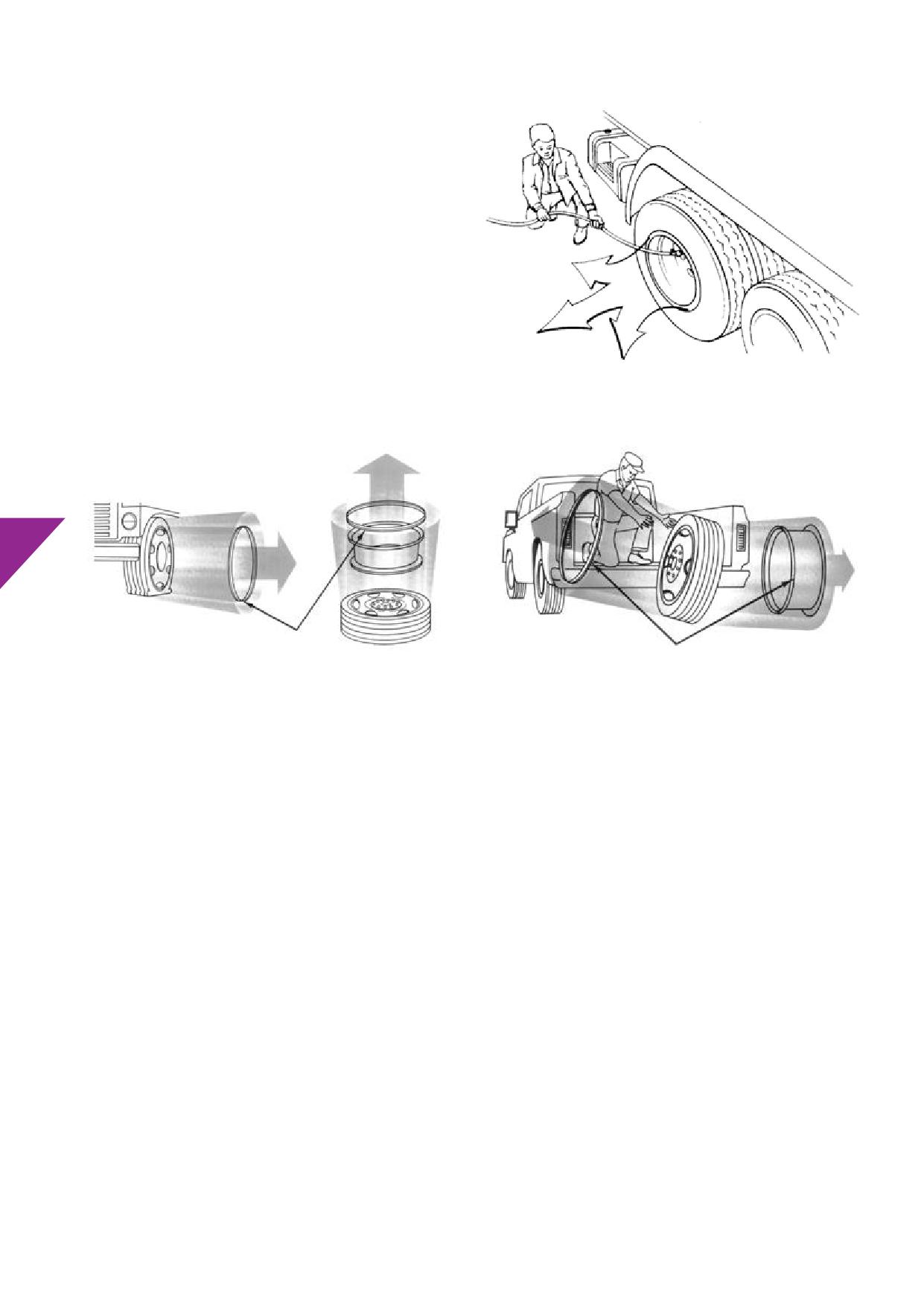
IMPORTANT
When infl
a tyre, stay out of the trajectory. See graphics 7-15,
7-16 and 7-17. DO NOT stand or lean any part of your body against,
or reach over, the approved restraining device or tyre cage during
infl
IMPORTANT
Look for distortions, undulations, or other irregularities in the tyre
sidewall. Pay attention to any popping or snapping sounds. If ANY
of these conditions are present: STOP! DO NOT approach tyre.
Before removing the assembly from the approved restraining
device or tyre cage (picture 7-14), completely defl
the tyre
remotely. Remove the clip-on air chuck. Mark tyre as damaged
for a potential “blow out”. Mark tyre immediately unserviceable,
non-repairable and scrap.
Graphic 7-15
7
Trajectory
Trajectory
Graphic 7-16
Graphic 7-17
8. Do not over-infl
Use the tyre or vehicle manufacturers’ recommended pressures, but under no circumstances exceed cold tyre
pressure as roll stamped on the wheel. If no popping or snapping sounds are present, remove the clip-on air chuck, install the valve core,
and adjust the infl
pressure to the recommended operating infl
pressure.
9. Before removing the tyre wheel assembly from the restraining device or tyre cage, always visually inspect for proper and concentric
seating of the beads and all parts.
10. Conduct a fi inspection. Heavy-Duty vehicle tyres have a “guide rib” or "mounting ring" moulded into the sidewalls next to the tyre
beads. See picture 7-18. When the tyre is infl
this moulded ring should be evenly spaced from the rim fl
all the way around the
wheel. See picture 7-19. Check the position of the mounting ring before removing the assembly from the approved restraint device or
tyre cage.
If the rib or ring and wheel are not concentric, defl
the assembly in the cage. After demounting the tyre re-lubricate, re-mount and
re-infl
the tyre in the approved restraint device or tyre cage. Repeat step 4 to 9.
34

Picture 7-18
Picture 7-19
11. Check the tyre/wheel assembly for air leaks. Install a suitable valve dust cap. Valve dust caps with an air seal are recommended.
7
35
8. Defl ting and demounting tubeless
tyres from Alcoa® Wheels
8.a. Before defl
and demounting
If there is known or suspected damage to the tyre or wheel or if
the tyre has been operated at 80% or less of its recommended
operating pressure, let the assembly cool down to ambient
temperature fi
Completely defl any tyre by removing the
valve core before removing the tyre/wheel assembly from the axle.
8.b. Machines, tools, and lubricants
Warning
Warning
Demounting damaged tyres or wheels can lead to an
An aluminium wheel can be structurally weakened by
explosive separation of tyres and wheels.
excessive heat. See Section 13.d. Heat damage.
Explosive separations of tyres from wheels can cause serious
Tyre/wheel assemblies, using wheels that have been
injury or death.
exposed to excessive heat, may experience a sudden and
unpredictable tyre/wheel separation causing serious injury
8
or death.
Inspect tyres and wheels for damage before removing
from vehicle. If damage is found, the tyre must be
completely defl
before loosening nuts. Immediately and
Immediately and permanently remove any wheel from
permanently remove damaged tyres or wheels from service.
service that has been subjected to excessive heat such as a
tyre fi
wheel bearing failure or braking system drag / seize
or a high-pressure tyre/wheel separation.
8.b.i. Machines
IMPORTANT
• Not all tyre mounting / demounting machines work the same.
• If using a tyre mounting / demounting machine on aluminium
Be sure to read the operating or instruction manual for your
wheels, care should be taken to prevent gouging the wheel.
particular machine before attempting to mount or demount
• Contact of parts of the machine with the wheel while operating
tyres. Follow the particular operating and instruction manual.
can cause deformation of the metal or wheel.
• Use special fi
for aluminium wheels on the machine’s
• Impacts or forces can structurally damage the rim or wheel and
chuck for clamping aluminium wheels. See for example pictures
cause cracks with air loss as a result.
8-9 and 8-10.
8.b.ii. Tools
Use the proper tools to demount or mount tyres and wheels. Refer to “Typical Tyre Service Tools”. See Section 6.b.
• NEVER strike the tyre and/ or the wheel with a hammer to unseat the beads.
• DO NOT use slide impact bead unseating tools with the risk of damaging bead seats, safety hump or drop well.
• Keep tyre tools smooth. Use them with care.
3
6
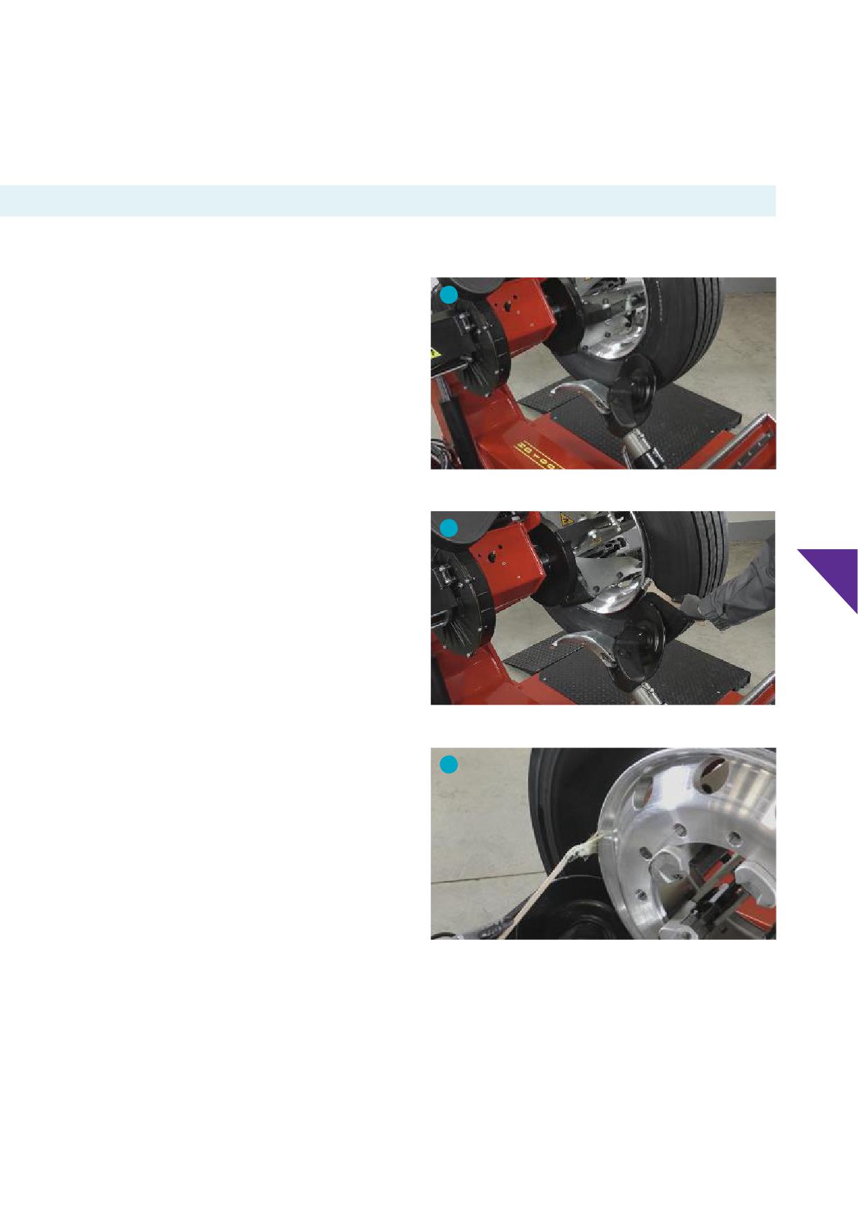
8.b.iii. Lubricants
Useanon-fl
vegetable or soap-based lubricant on bead seats and other rim surfaces which is pH neutral. Lubricate the tyre beads
and the bead seats of the wheel to make tyre demounting easier after defl
and before demounting the tyre from the wheel.
8.c. Defl
and demounting
IMPORTANT
Always completely defl
the tyre/wheel assembly before
3
attempting to demount a tyre from the wheel. Remove the valve
core and insert a wire down the valve stem to ensure complete
defl
Never demount a tyre from a wheel unless it is
completely defl
Note:
Most Alcoa® Wheels typically have symmetrical drop centres so
tyres can be demounted from either side. However, on certain
aluminium wheels, the short side of the drop centre well is located
on the disc side. See Section 6.g.
Picture 8-1
1. Identify the short side of the drop centre well. Single-piece
tubeless rims and wheels must be demounted from the
short side of the drop centre well. I.e. tyre beads should be
4
demounted over the rim fl
closest to the wheel well.
8
2. Remove valve core to defl
the tyre, prior to remove the
assembly from the vehicle. Insert a wire down the valve stem to
ensure complete defl
3. Position the assembly on the machine. Lift the assembly to
enable the bead breaker disc to contact the back bead of the
tyre without contacting the wheel rim fl
Picture 8-2
4. Rotate the wheel while moving the bead breaker disc towards
the drop well, without contacting the wheel. Apply an approved
lubricant on the tyre bead and bead seat of the wheel while
5
rotating the wheel.
5. Move the bead breaker disc to the front and repeat step 4.
Picture 8-3
37
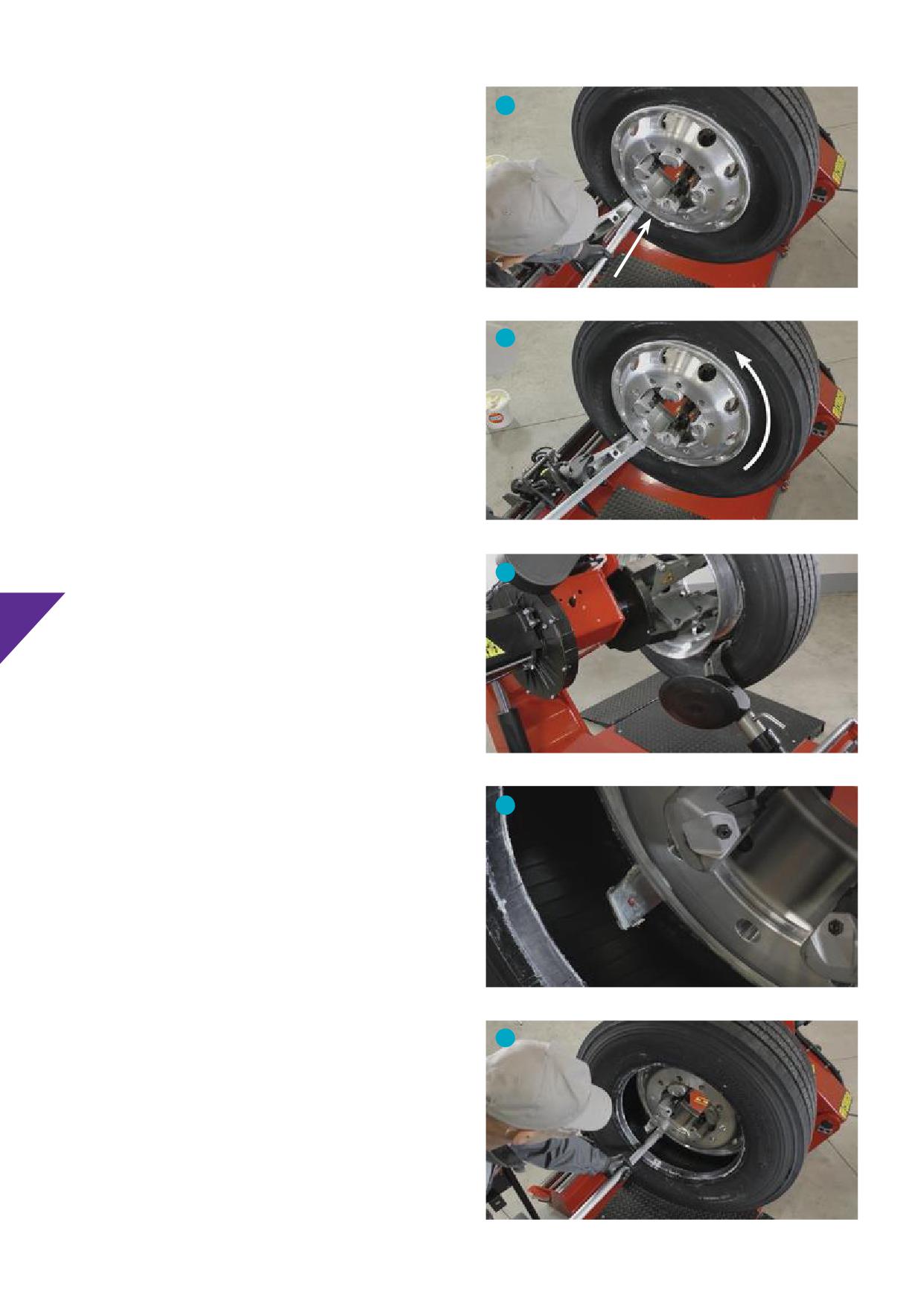
6. Position the “tool arm” in level with the rim fl
(without
6
contacting it) making sure the “tool arm” engages the bead
completely. Insert the “lever” just below the “tool arm” and
rotate the wheel clockwise until the rear bead is completely
demounted.
7. Move the “tool arm” to the back and position it in level with the
rim fl
in the front (without contacting it) making sure the
“tool arm” engages the back bead completely. Insert the “lever”
just below the “tool arm” and rotate the wheel clockwise until
the front bead is completely demounted.
Picture 8-4
IMPORTANT
6
Do not cut or damage the bead of the tyre.
Picture 8-5
7
8
Picture 8-6
7
Picture 8-7
7
Picture 8-8
38
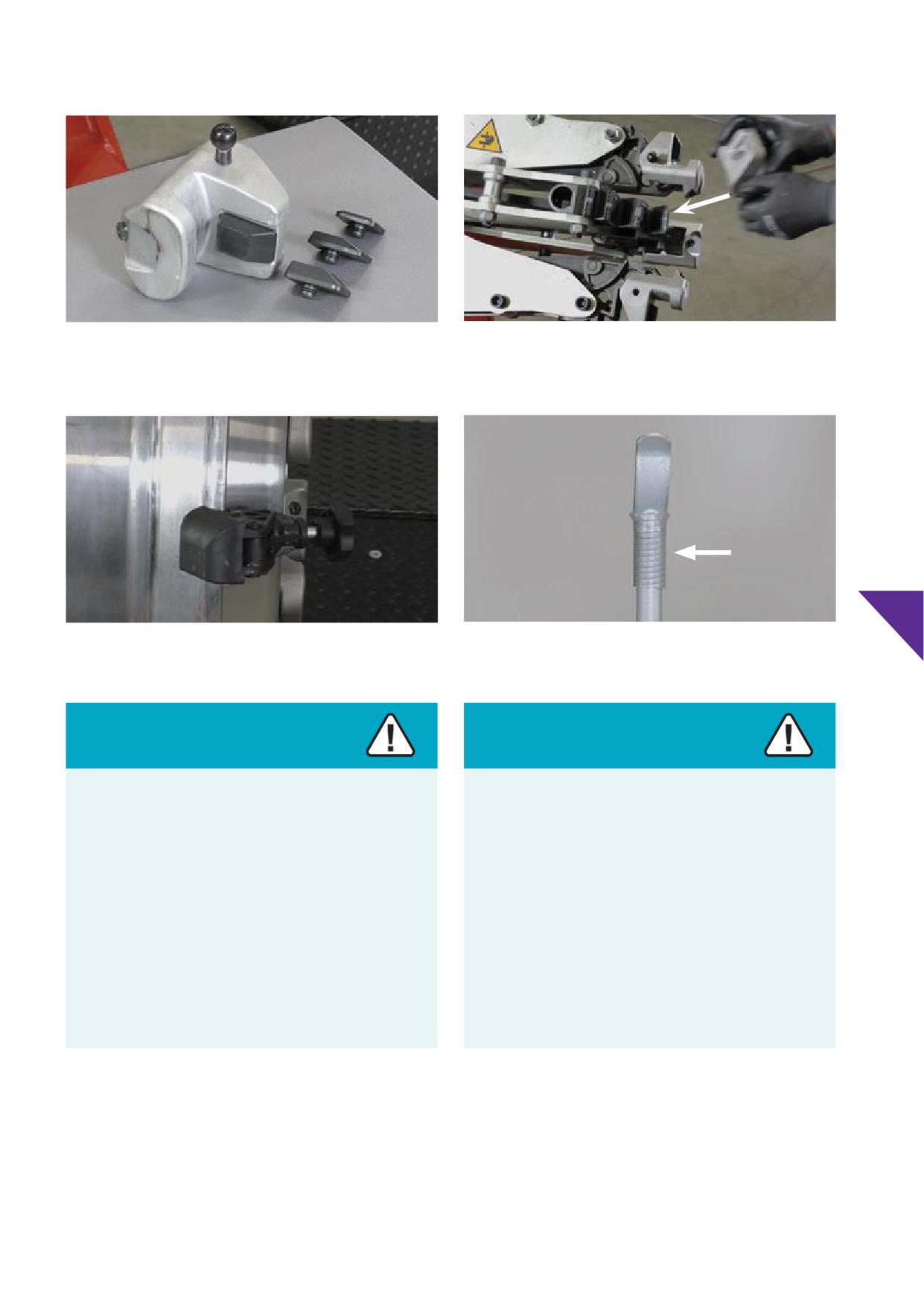
Fixture for clamping aluminium wheels
Fixtures attachment to machine’s chucks
Picture 8-9
Picture 8-10
Plastic mounting aid used when mounting
Lever - with plastic protection- used when demounting
8
Picture 8-11
Picture 8-12
Caution
Caution
Do not use a hammer or a slide impact tool on wheels to
Demounting tyres with tyre changer
avoid damage of rim fl
bead seats, safety hump or
drop well of a wheel.
Do not contact the wheel, i.e. rim fl
bead seat, safety
hump or drop centre, with the bead breaker disc while
Impacts on rim fl
bead seats, safety hump or drop well
pushing the beads of the tyre towards the drop well.
of the wheel may cause cracks at a later stage with air loss as
a result.
Damaging, carving, denting, or deforming the metal with the
“bead breaker disc” may cause cracks at a later stage with air
Make sure to unseat tyre beads without damage to rim
loss as a result.
fl
bead seats, safety hump or drop well.
Make sure to unseat tyre beads without contacting rim
fl
bead seats, safety hump or drop well with the “bead
breaker disc” or other parts from the tyre changer.
39
9. Balancing Alcoa® Wheels with adhesive
weights
Alcoa® Wheels are fully machined and do not require balancing.
Powder, granulate, liquid balancers or liquid
However, the tyre-wheel combination may need to be balanced.
sealants
Internal balancing compounds (powder or liquid) are not
recommended. Use of coated balancing weights is recommended
• Balancing with powder, granulates or liquids are not
to avoid staining and corrosion of wheel surface.
recommended, nor sealing with liquid sealants.
Powder, granulate or liquid balancers as well as liquid sealants
Regulations from the European Commission (2000/53/EG) banned
may harm the inner liner of tubeless tyres. For information
use of lead for balancing of cars and vans up to 3.5T GVW as from
consult the tyre manufacturers’ recommendations.
2005. At the time of writing this service manual, balancing weights
• The use of liquid tyre balancers or sealants in Alcoa® Wheels may
used for commercial vehicles over 3.5T GVW may still contain lead.
cause extremely rapid corrosion of the valve hole area, drop
centre and bead seat areas. Wheels with severe corrosion at the
NOTICE
valve hole, drop centre and bead seat areas are unsuitable for
service.
• Always follow the recommended procedures of the balancing
• The policy of Howmet Wheel Systems is not to endorse any
weight manufacturer. It may be necessary to reduce the tyre
specifi brand or entity of balancing powder or balancing
pressure when installing clip-on weights to allow clearance for
®
granulates. The use of powder or granulate balancers in Alcoa
the weight's clip between the tyre and rim fl
Wheels may cause clogged valves. A fi
valve core is
• Adhesive weights should be applied only to a clean surface
recommended when using balancing powder or granulates.
per the recommended procedures of the balancing weight
manufacturer. Balance weights should be installed in a location
NOTICE
where they will not contact the brake -, steering - or suspension
components during vehicle operation.
The use of balancing powders and granulates will not void the
• Proper pre-cleaning is an essential factor for adhesive balance
limited warranty (See Section 2), unless inspection of the wheel
weights. It is recommended to evaluate the surface cleaning
shows anomalies related to its use.
techniques and products with the manufacturer or supplier
9
of balancing weights. Relocating wheels from a cold place to a
Alcoa® Wheels corroded by the use of liquid tyre balancers or
warmer place may cause condensation on wheel surfaces which
sealants will not be replaced under the Howmet Aerospace limited
can aff the adhesion negatively.
warranty. See Section 2.
Improperly installed weights could ‘come off during use and
damage the vehicle and/or surrounding objects or cause personal
injury.Excessiverim fl
wear (see Section 13.g.) could dictate
the use of‘stick-on’ or adhesive balancing weightsif thereis
inadequate rim fl
to properly hold a clip-on (knock on) style
weight.
Caution
The usage of clip-on style balancing weights will not
adequately engage at the hardened Dura-Flange® surface.
Clip-on balancing weights are not recommended for
Dura-Flange® Alcoa® Wheels and may disengage from the
wheel causing serious injury or death.
Howmet Wheel Systems recommends adhesive style
balancing weights for Dura-Flange® Alcoa® Wheels.
4
1
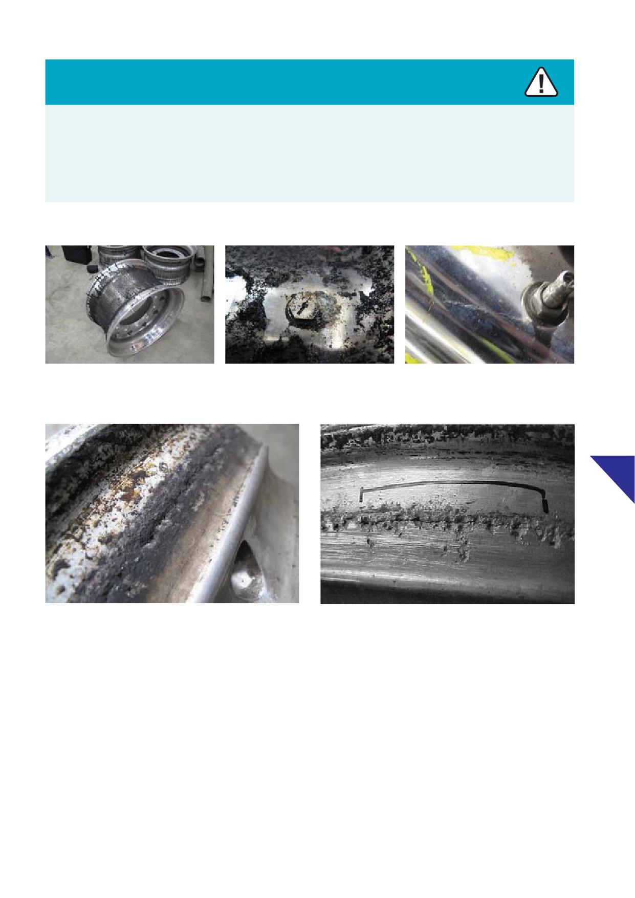
Caution
The use of liquid tyre balancers or sealants in Alcoa® Wheels may cause galvanic corrosion at the valve hole area. It may also corrode
the valve and/or may cause extremely rapid corrosion of the wheel rim surface.
Corrosion can initiate hairline cracks and air loss.
Do not use liquid tyre balancers or sealers. Always infl
tyre/wheel assemblies with dry air only.
The valve or valve hole may not function properly due to corrosion and allow loss of air pressure.
Picture 9-1
Picture 9-2
Picture 9-3
Corroded bead seats are not airtight and will allow loss of air pressure.
9
Picture 9-4
Picture 9-5
Severely corroded wheels are unsuitable and should be permanently removed from service.
NOTICE
Alcoa® Wheels corroded by the use of liquid tyre balancers or
sealants will not be replaced under the Howmet Wheel Systems
limited warranty. See Sections 2, 13.i.ii. and 13.i.iii.
40
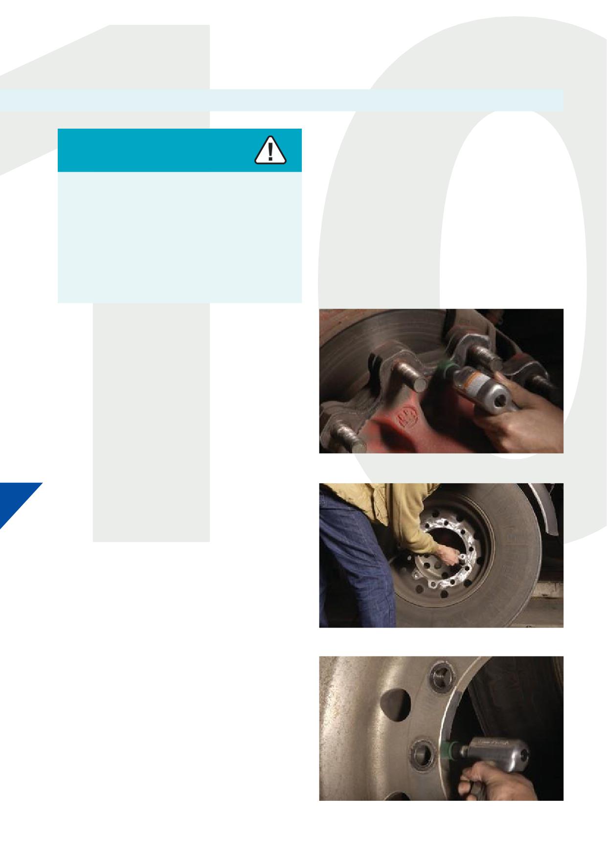
10. Wheel installation
10.a. Wheel installation preparation
For free training on proper installation and maintenance or for the
most recent updates of online materials, contact Howmet Wheel
Warning
Systems via web page www.alcoawheelseurope.com.
Wheels that are not properly installed or maintained may not
be safe.
Failure to follow proper wheel installation or maintenance
practices may result in serious injury or death.
Follow the proper wheel installation and maintenance
practices as contained in this Service Manual for Alcoa®
Wheels.
STEP 1
Clean the mating face of the hub / axle, remove dirt, oxidation, and
paint. Do not apply any rust inhibitor, surface coating, grease, oil, or
paint. Follow the recommendations of axle / vehicle manufacturers.
Picture 10-1
10
STEP 2
Clean the mating face of the wheel (disc), remove dirt, oxidation,
and paint. Do not apply any rust inhibitor, surface coating, grease,
oil or paint. If the mating face(s) of wheel(s) is (are) severely
corroded, remove wheel(s) from service.
Picture 10-2
STEP 3
Clean the inner side of the hub bore of the wheel. Remove dirt,
oxidation, and other foreign residues.
Picture 10-3
42
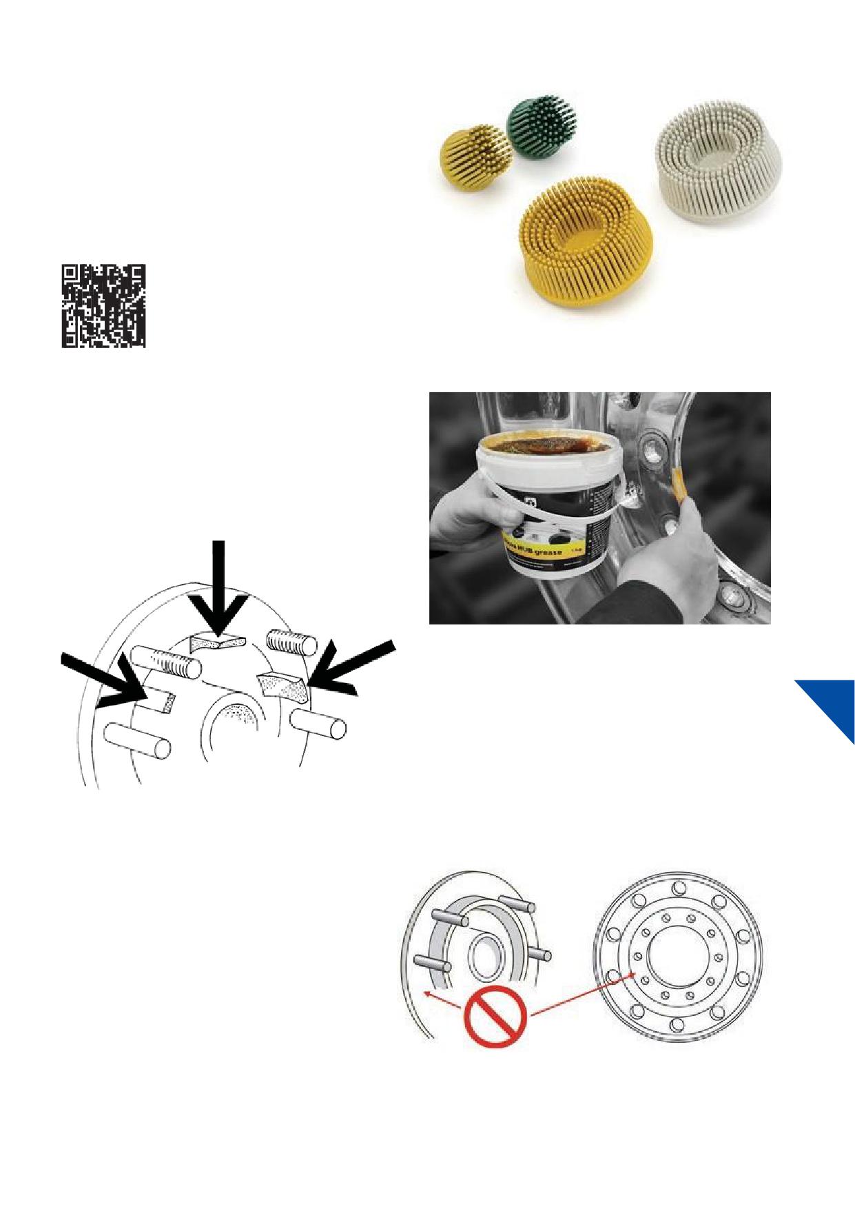
Picture 10-4:
The abrasive tools used in pictures 10-2 and 10-3 are available from
authorized distributors of Alcoa® Wheels, reference: Bristle Discs for
Alcoa® Wheels.
For documentation contact Howmet Wheel Systems at: www.
alcoawheelseurope.com
Picture 10-4
STEP 4
Apply a layer of HUB grease, or another grease that does not
contain metal or water, on the inner side of the hub bore of the
wheel. See Picture 10-5.
Alternatively apply the same product at the pilot tabs, spigots or
centring edge of the hub / axle. See Graphic 10-6.
Picture 10-5
10
Graphic 10-6
Note:
Do not apply any rust inhibitor, surface coating,
grease, oil or paint on either mating face of hub or
mating face of wheel (disc). In case of an inner dual
fi
wheel this applies to both sides of the wheel
disc. See graphic 10-7.
Graphic 10-7
43
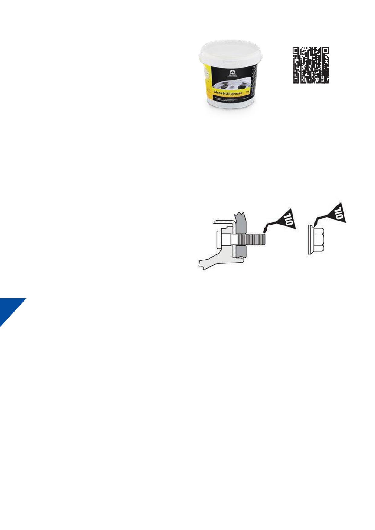
HUBgrease for Alcoa® Wheels is available from
authorized distributors of Alcoa® Wheels. See picture
10-8.
Picture 10-8
STEP 5
For nuts used on hub piloted wheels apply two drops of motor oil
to the fi two threads of the tip of each stud (see graphic 10-9)
and between the nut and the integrated washer (see graphic
10-10). This will minimize corrosion between the mating threads.
Lubrication is not necessary with new hardware.
Check if the integrated washer freely rotates on nut applying some
pressure on the integrated washer towards nut while rotating.
Fit nut onto the stud and check if the nut can freely rotate by hand
Graphic 10-9
Graphic 10-10
turning the nut towards the hub.
10
NOTICE
Do not use any lubricants that are water based or greases
containing metals (e.g. copper grease). Water based products can
lead to accelerated corrosion and products containing metals allow
galvanic corrosion.
For information contact Howmet Wheel Systems via webpage
44
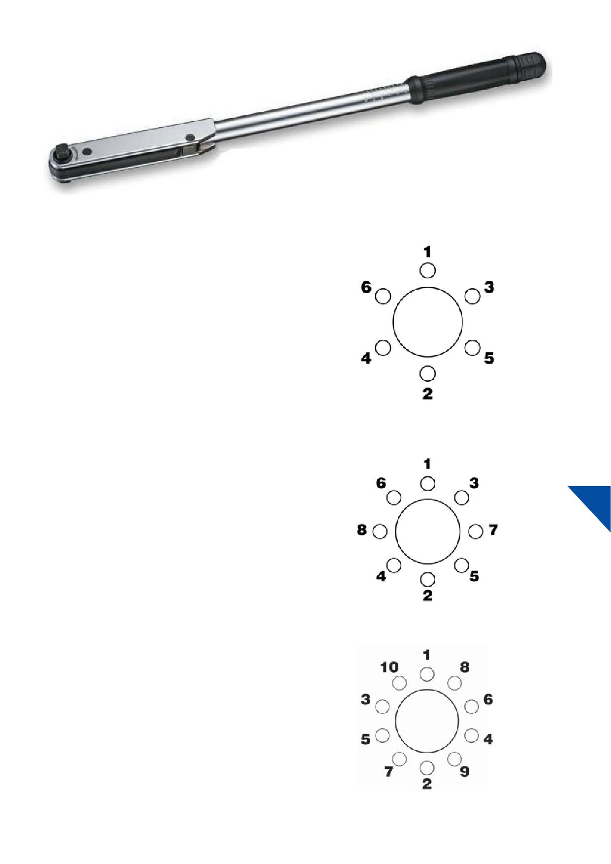
Picture 10-11: Torque wrench
STEP 6
1. Refer to the owner’s manual of the vehicle or axle for correct
torque value: Nm (kgf).
2. Hand tighten all nuts.
3. Impact wrenches, if used, should be carefully adjusted to apply
torques within or below the limits recommended. See section
12.b.
4. Tighten to the recommended torque with a calibrated torque
wrench (Picture 10-11) following the proper sequence. See
graphics 10-12, 10-13, 10-14 and Section 12.b.
5.
Graphic 10-12
After each wheel mounting, torque should be checked with a
calibrated torque wrench (Picture 10-11).
IMPORTANT
After 8 - 80 kilometres or 5 - 50 miles of operation torque should be
10
recheckedunless vehicle/axlemanufacturer or your documented
fl
practices determine otherwise.
Check torque frequently from then on.
NOTICE
If nuts require frequent tightening, studs break frequently, wheel
Graphic 10-13
nut washers break or bolt holes are pounding out, hardware and
mounting practicesshould be reviewed.
For free training on proper installation and maintenance or for the
most recent updates of online materials, contact Howmet Wheel
Systems via web page www.alcoawheelseurope.com
For additional information see Section 12.a.
Graphic 10-14
45
10.b. At wheel installation
Check for and replace bent, broken, cracked or damaged studs.
When replacing broken studs, always replace the studs on each
side of the broken stud.
Warning
If two or more studs are broken, replace all the studs for that
Wheels that are not properly installed or maintained may not
wheel position. Check with the stud manufacturer for regular
be safe.
maintenance and stud replacement practices.
Failure to follow proper wheel installation or maintenance
All wheel fastener hardware should be grade 8 or metric conversion
practices may result in injury or death.
10.9. Follow the hardware manufacturers’ recommendations when
replacing studs. See Section 11.b.iii.
Follow the proper wheel installation and maintenance
practices as described in this Section.
IMPORTANT
• Perform a wheel fi
check to ensure proper clearance from any obstructions. See ‘Wheel fi
check’
Section 5.d.
• Do not exceed maximum wheel load. Customer must compare OEM vehicle axle load ratings to maximum
wheel load rating.
• Refer to tyre manufacturers’ recommendations for proper tyre pressure, before mounting the tyre.
1. Make sure all wheel nuts are properly torqued. Check them
4. Do not introduce any foreign objects such as spacers or top
10
often. See Section 12.a. If the wheel is loose, the holes will
hats (hub caps or covers) into the contact surface areas of the
pound out or deform. If some nuts are tight and others are
mounting system unless approved by Howmet Wheel Systems.
loose, the wheel may develop cracks or studs may break. This
Do not paint, powder coat, or otherwise coat Alcoa®
condition may cause wheels to loosen and disengage from the
Wheels.
vehicle. Dirt streaks or rust radiating from bolt holes and / or
vent holes can indicate loose nuts. See Section 13.h.
5. Additional care should be used when mounting Dura-Bright®
surface treated Alcoa® Wheels, since minor nicks and scratches
2. Ensure the end of the wheel wrench is smooth or cover the
cannot be polished out. See Section 14.b. for specifi cautions,
wheel mounting surface with a protective shield prior to
care, and maintenance procedures.
tightening the nuts. The wheel wrench end will mar the wheel
around the nuts if it is not smooth.
6. Discmates for Alcoa® Wheels or nylon protection gaskets are
designed to be placed between wheels and hub or brake drum
3. Keep all component contact surfaces smooth and clean. Dirt or
contact surfaces and as well as between the dual mounted
projections on mounting surfaces may lead to lose or loosing
wheels contact surfaces. See Section 4.h. Discmates for Alcoa®
wheels. Remove all projections resulting from burrs, nicks, etc.
Wheels or nylon protection gaskets are recommended to be
Take care that loose dirt does not fall onto mounting surface
replaced when the tyre/wheel assemblies are removed and
during assembly.
reinstalled.
46
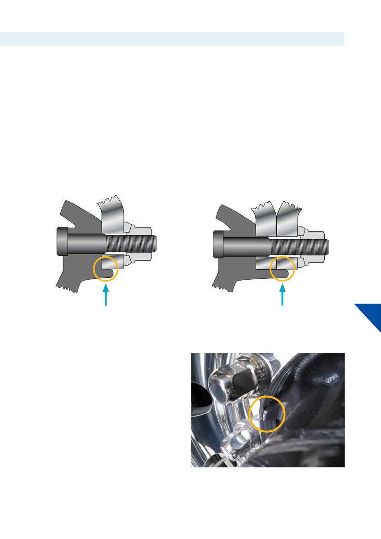
10.c. Hub centring
All European type Alcoa® Wheels for medium and heavy-duty
Measure the hub pilot tab length to make sure the hub properly
commercial vehicles are hub centred wheels. European type
centres the wheels. The pilot tab length for suffi
centring
Alcoa® Wheels have cylindrical bolt holes and are not suitable for
must be 5 mm or more for single mounting (Graphic 10-15) and 1x
bolt centring with conical or spherical nuts: never use any kind
disc thickness + 5 mm or more for dual mounting (Graphic 10-16).
of this type of hardware on wheels with cylindrical bolt holes.
In both cases dimensions are excluding bevelled edges. Longer
For reference consult the Specifi
Sheet for Alcoa® Wheels
spigots make mounting easier.
available from the web or consult Howmet Wheel Systems.
Hubs designed for steel hub piloted wheels may not have enough
pilot tab length to locate dual aluminium wheels. Pay close
attention to pilot tab length, particularly when converting from steel
to aluminium duals.
10
Graphic 10-15
Graphic 10-16
NOTICE
Always apply HUBgrease for Alcoa® Wheels or another grease
that does not contain metal or water, on the pilot tabs or spigots
(Picture 10-17) to reduce corrosion and make it easier to remove
wheels when replacing tyres or other components for service.
Picture 10-17
47
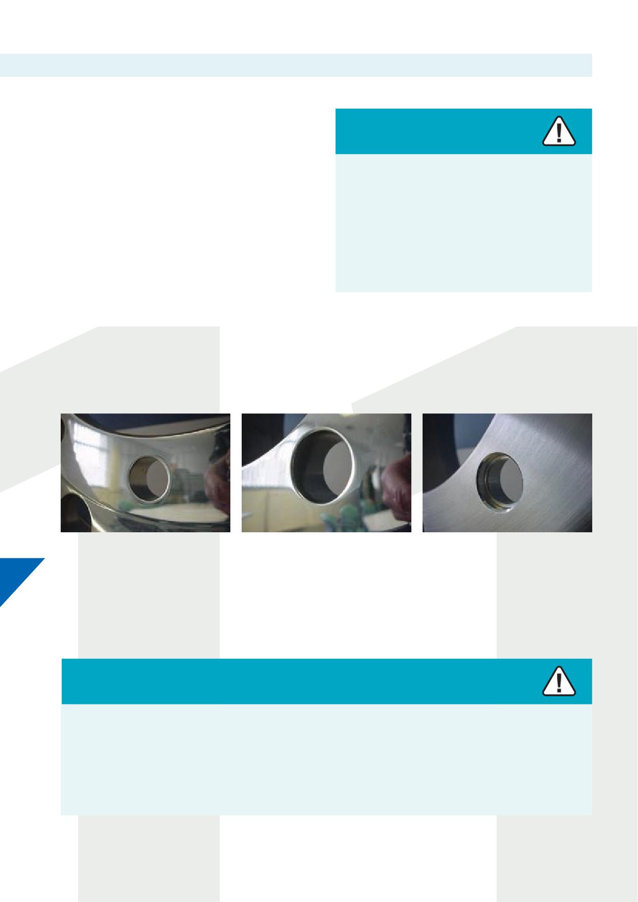
10.d. Disc thickness and thread engagement
The mounting fl
or disc of Alcoa® Wheels for medium and
heavy-duty vehicles is thicker (19.1 to 28.6 mm) than the mounting
fl
of steel wheels (9 to 16 mm) and therefore requires diff
Warning
mounting hardware.
Insuffi
engagement of threading between stud and nut
For correct mounting of Alcoa® Wheels use:
may cause cracking or breaking of the stud.
• Longer (replacement) studs with standard nuts, as described in
Section 11.a., or
Cracking or breaking studs may result in separation of the
• Sleeved nuts (available from Howmet Wheel Systems) with
tyre/wheel assembly from the vehicle resulting in serious
standard length studs, as described in Section 11.b.
injury or death.
For reference see the latest Specifi
Sheet for Alcoa® Wheels
Follow the proper wheel installation and maintenance
with details about wheel sizes, part numbers, dimensional
practices as described in this Section.
properties such as disc thickness, bolt hole diameters and more.
11. Mounting hardware
Depending on the mounting hardware or type of mounting an Alcoa® Wheel may be off
with diff
bolt hole diameters:
Picture 11-1
Picture 11-2
Picture 11-3
11
From left to right various bolt hole diameters for M22 or 7/8” bolt / stud diameters:
• Picture 11-1
26 mm bolt hole for standard nuts and longer studs. See Section 11.a.
• Picture 11-2
32 mm bolt hole for sleeved nuts and standard studs. See Section 11.b.
• Picture 11-3 Bolt hole a.k.a. 'dual hole' for Volvo OEM hardware only. See Section 11.d.
Warning
Use of chrome-plated wheel nuts, which have chrome plating on the surfaces that contact the wheel, can cause reduced and
inconsistent wheel clamping.
This condition can cause wheels to loosen and disengage from the vehicle, causing serious injury or death.
Never use wheel nuts with chrome-plated contact surfaces. Use only recommended hardware on Alcoa® Wheels. See Sections 4.c. and
11.b.iii.
48
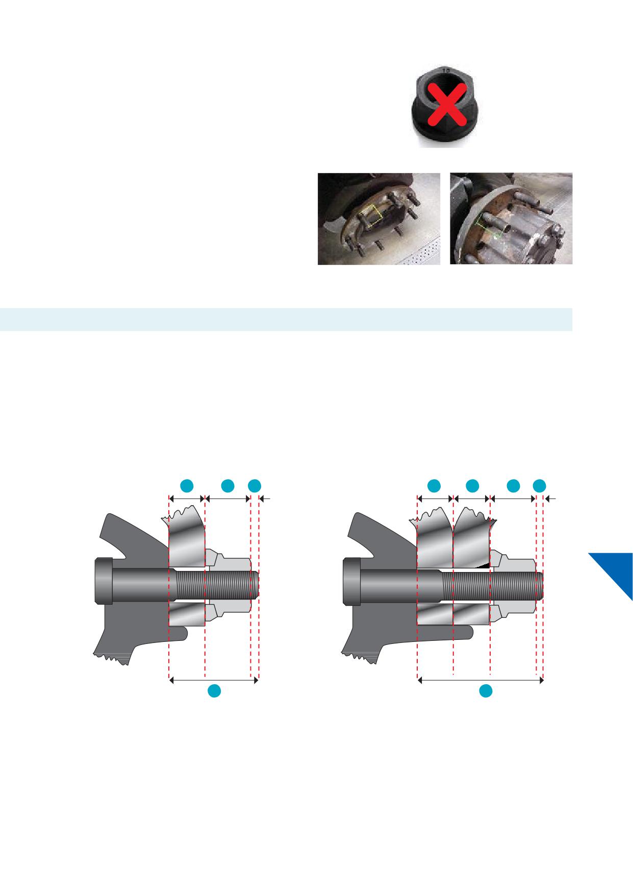
IMPORTANT
1-piece fl
nuts are not approved for use on any Alcoa® Wheels
application. See picture 11-4.
Stud standout is critical to understand for the proper application of
the various nuts used for these three diff bolt hole diameters.
The stud standout must be checked very carefully.
Picture 11-4
The stud standout is measured from the fl mounting surface
of the hub, or drum brake, which is in contact with the disc of the
wheel, to the outer end of the stud.
The stud standout on steer axle / single mounting (picture 11-5) and
stud standout on drive axle / dual mounting (picture 11-6) must be
checked both for suffi
length.
Picture 11-5
Picture 11-6
11.a. Mounting Alcoa® Wheels with standard 2-piece fl
nuts and replacing wheel studs
Alcoa® Wheels with this type of mounting system require longer studs than for steel wheels. The stud standout must be long enough to
cover the disc thickness of single or dual mounted aluminium wheels, the height of the wheel nut and an additional two threads of the stud
protruding from the top of the nut.
For single mounting the minimum stud standout required =
For dual mounting the minimum stud standout required = 2x disc
1x disc thickness of the Alcoa® Wheel + height of standard nut +
thickness of the Alcoa® Wheel + height of standard nut + 2 full
2 full threads, 3 mm** with M22, M20 or M18 x 1.5 studs.
threads, 3 mm** with M22, M20 or M18 x 1.5 studs. See Graphic
See graphic 11-7.
11-8.
1
2
3
1
1
2
11
4
4
Graphic 11-7
Graphic 11-8
1. Disc thickness of the Alcoa® Wheel
** or 2 full threads in case of 7/8”-11 BSF studs (Scania) or
2. Height of standard nut
7/8”-14 UNF studs (Volvo >2004)
3.
2 full threads
4. Total stud standout
49
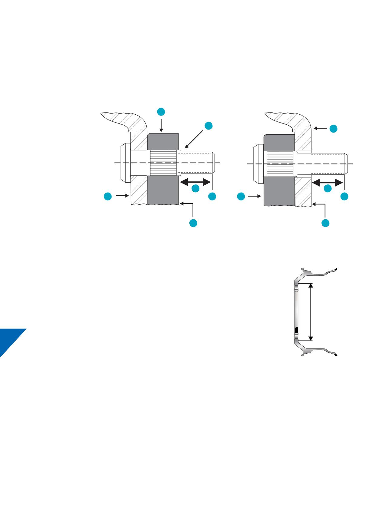
11.a.i. How to measure stud standout (axles with drum brakes)
Stud standout is measured from the axle end mounting surface:
• I.e., from the hub for disc brake operated axles and inboard mounted drums of drum brake operated axles to the fi
complete thread at
the outside end of the stud. See graphic 11-9.
• I.e., from the drum for outboard mounted drums of drum brake operated axles to the fi
complete thread at the outside end of the
stud. See graphic 11-10.
Inboard mounted drum
Outboard mounted drum
1
7
3
1. Hub
2. Inboard drum
3. Outboard drum
4. Mounting surface
5. First full thread
6. Stud standout
7. Exposed shoulder
6
6
2
5
1
5
4
4
Graphic 11-9
Graphic 11-10
IMPORTANT
Check for bottom out” when using sleeved nuts at exposed shoulder. See graphic 11-9 (7).
• The (sleeved) nut must be able to clamp the wheel or wheels.
• See Section 11.b.ii. for reference and information about ‘bottom out’ condition.
Measure the diameter of the exposed shoulder (See graphic 11-9 (7)) and compare with bolt hole diameter of
wheel:
• The diameter of the exposed shoulder must measure less than the diameter of bolt hole.
Backup
• The wheel mating face must be fl and in full contact with the hub- or drum mating faces.
11
Check the shape and measure the diameter of the mounting face. See graphic 11-11.
• Wheels mounted on hub- or drum mating faces that are not circumferential need to be checked regularly.
See section 13.h.i.
• The hub- or drum mating face must comply with the recommended diameters.
See section 5.c. chart 5-3 or section 13.h.i. chart 13-44.
Graphic 11-11
11.a.ii. Confi
proper stud standout
For safe mounting the stud standout must meet the following conditions. If not met, then the wheel studs must be replaced with wheel
studs that will meet the requirement. For use with standard 2-piece fl
nuts and replacing studs the minimal stud standout must be:
Single mounting:
Dual mounting:
• 1x disc thickness of an Alcoa® Wheel + height of nut + 3 mm for
• 2x disc thickness Alcoa® Wheels + height of nut + 3 mm for use
use with M22, M20 or M18 x 1.5 threads (or 2 full threads in case
with M22, M20 or M18 x 1.5 threads (or 2 full threads in case of
of other type of threading such as BSF or UNF).
other type of threading such as BSF or UNF).
• Example 1x 22.5 x 14.00 Alcoa® Wheel with 28.6 mm disc
• Example 2x 22.5 x 7.50 Alcoa® Wheels with 22.2 mm disc
thickness and a regular 2-piece fl
nut M22 x 1.5 result in a
thickness and a regular 2-piece fl
nut M22 x 1.5 result in a
stud standout of 28.6 + 27 + 3 = 58.6 mm. See graphic 11-7.
stud standout of 2x 22.2 + 27 + 3 = 74.4 mm. See graphic 11-8.
50
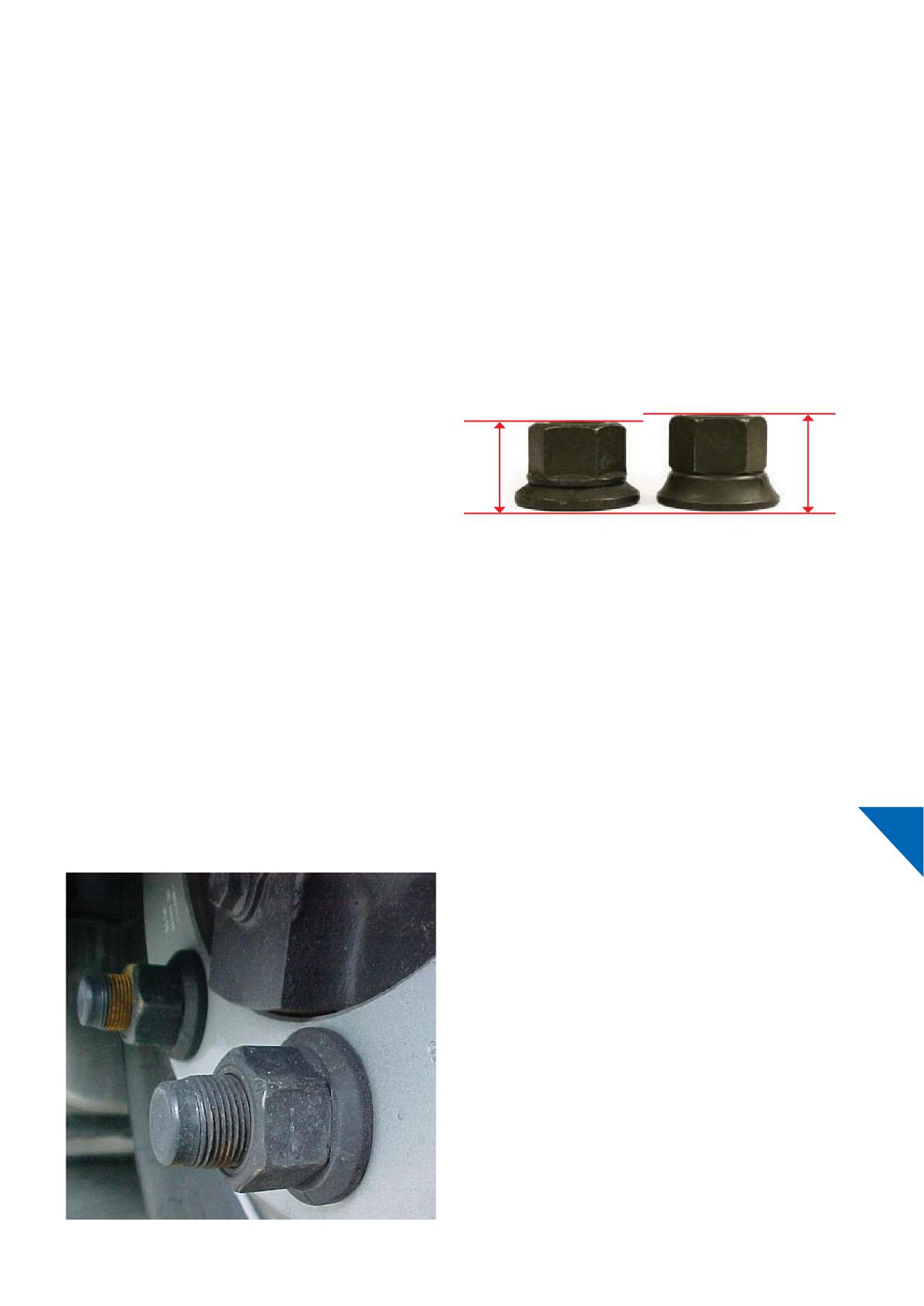
Mixed mounting:
For use with standard 2-piece fl
nuts and replacing studs the
minimal stud standout must be:
• 1x disc thickness wheel of Alcoa® Wheels + 1x disc thickness steel
wheel + height of nut + 3 mm for use with M22, M20 or M18 x 1.5
threads (or 2 full threads in case of other type of threading such
as BSF or UNF)
• Example 1x 22.5 x 9.00 Alcoa® Wheel with 20.5 mm disc thickness
and 1x 22.5 x 9.00 steel wheel with 13 mm disc thickness and a
regular 2-piece fl
nut M22 x 1.5 result in a stud standout of
1x 20.5 + 1x 13 + 27 + 3 = 63.5 mm
• See Section 4.h.
11.a.iii. Availability nuts
If hex nuts with greater overall height are used, more stud length is
required. See picture 11-12.
Standard nuts delivered and fi
by vehicle or axle OEM can be
used for mounting of Alcoa® Wheels.
Howmet Wheel Systems in Europe do not off OEM nuts. Consult
Picture 11-12
the manufacturers of vehicles or axles for availability of nuts.
11.a.iv. Availability studs
Prior to retrofi Alcoa® Wheels (with standard nuts and longer
studs) consult your truck, trailer, or axle OEM for the availability of
longer replacement studs with proper standout.
11
11.a.v. Extra-long studs
Some vehicle manufacturers off axles with “combined” or
extra-long stud lengths, suitable for both thinner disc steel wheels
and thicker disc aluminium wheels. In some cases, Alcoa® Wheels
can be mounted without replacing studs or use of sleeved nuts.
To determine correct and safe fi
follow the procedures as
described in this Section.
Picture 11-13
52
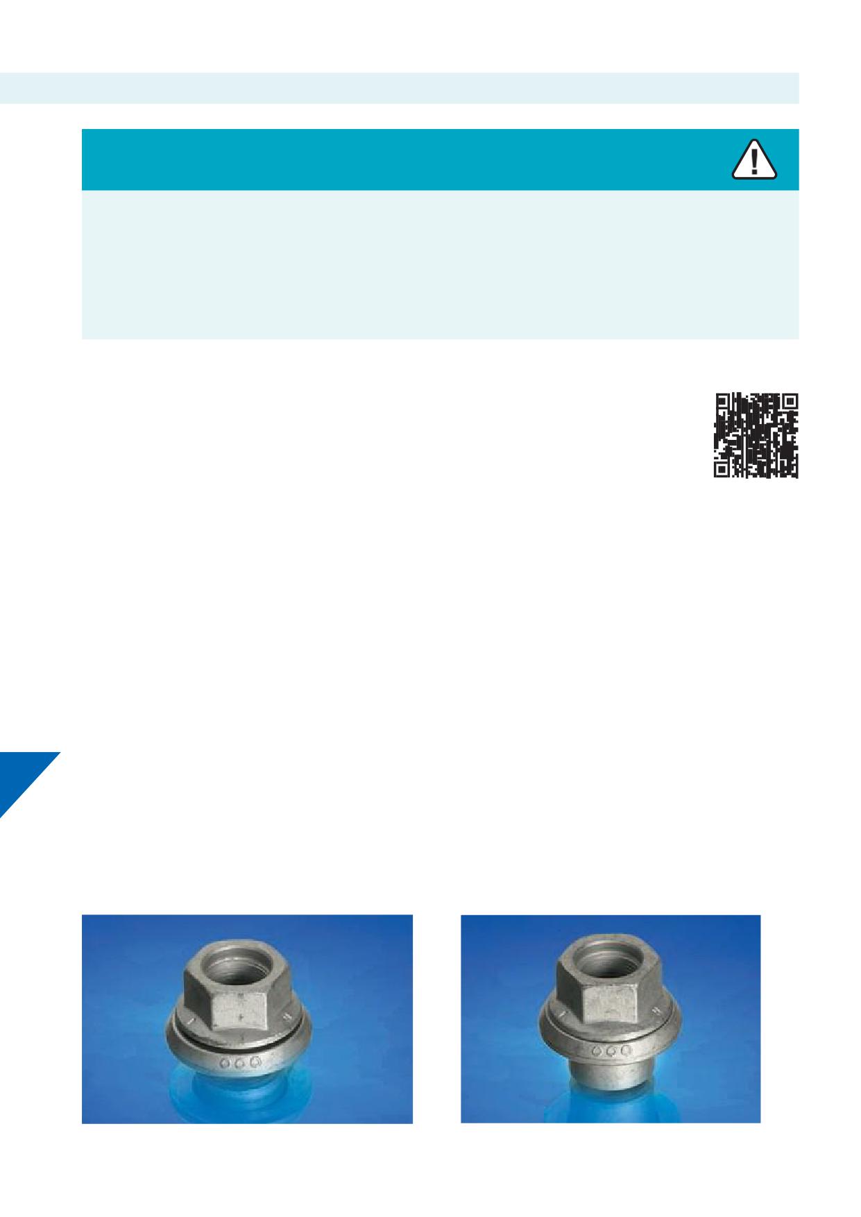
11.b. Mounting Alcoa® Wheels with standard length studs and sleeved nuts
Warning
Use of chrome-plated (sleeved) wheel nuts which have chrome plating on the surfaces that contact the wheel can cause reduced and
inconsistent wheel clamping.
This condition can cause wheels to loosen and disengage from the vehicle, causing serious injury or death.
Never use wheel nuts with chrome-plated contact surfaces. Use only recommended hardware on Alcoa® Wheels.
See Sections 4.c. and 11.b.iii.
IMPORTANT
1-piece fl
nuts (Picture 11-4) are not approved for use on any
For reference consult the Specifi
Sheet for
Alcoa® Wheels application.
Alcoa® Wheels for mounting hole diameters.
If in doubt consult Howmet Wheel Systems.
The standard wheel stud length can accommodate Alcoa® Wheels,
with more disc thickness compared to steel wheels, when a special
Note:
sleeved nut is used. The shank or sleeve of these nuts extends into
Wheels with 26 mm mounting hole diameter,
the larger diameter mounting holes and compensates the standard
either use longer studs with standard nuts (M22 x 1.5, 7/8”-11 BSF
stud length securing suffi
thread engagement.
or 7/8”-14 UNF) or use standard studs with sleeved nuts (M18 x 1.5).
Only use the Alcoa® Wheels with an appropriate mounting hole
Check the specifi
of the studs on the vehicle.
diameter to allow the sleeve of the nut to easily pass through it.
To ensure correct mounting with sleeved nuts, there must be
Sleeved nuts are available for:
enough thread engagement with the stud:
Wheels with 32 mm mounting hole diameter for mounting with
The recommended length of engagement between the threads of
sleeved nut:
the stud and the sleeved nut is equivalent to 95% or more of the
• M22 x 1.5 (Metric, Volvo 2005 >)
diameter of the stud.
• 7/8”-11 BSF (Scania)
•
7/8”-14 UNF (Volvo > 2004)
The minimum recommended number of threads engaged
between the stud and sleeved nut is:
Wheels with 30 mm mounting hole diameter for mounting with
11
sleeved nut:
• 14 full turns for M22 x 1.5 (Metric, Volvo 2005 >)
• M20 x 1.5 (Metric)
• 13 full turns for M20 x 1.5 (Metric)
• 12 full turns for M18 x 1.5 (Metric)
Wheels with 26 mm mounting hole diameter for mounting with
• 10 full turns for 7/8”-11 BSF (Scania)
sleeved nut:
• 12 full turns for 7/8”-14 UNF (Volvo > 2004)
• M18 x 1.5 (Metric)
Picture 11-14
Picture 11-15
51
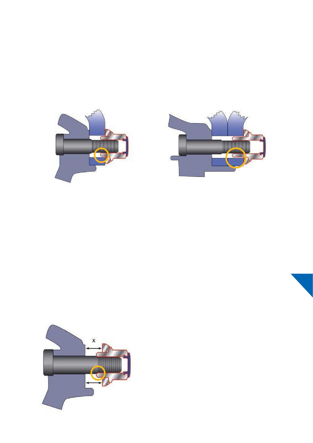
11.b.i. How to check suffi
thread engagement
Engage a single wheel or dualled wheels to the hub with at least two nuts securing the wheels. Tighten one nut by hand and count the
number of full turns till the nut sits snugly.
Do not centre hub piloted type wheels with sleeved nuts.
The sleeves of the nut do NOT centre the wheel(s); this mounting system still requires a hub piloting or hub centring axle. This applies to
both single and dual mounted wheels. The pilot tab length for suffi
centring must be 5 mm or more for single mounting or 1x disc
thickness (of the inner wheel) + 5 mm or more (for the outer wheel) for dual mounting, excluding bevelled edges of the pilot tabs.
Graphic 11-16
Graphic 11-17
Single mounted wheels require sleeved nuts with a short sleeve
Dual mounted wheels require sleeved nuts with a long sleeve
Short- and long-sleeved nuts are available from Howmet Wheel Systems in thread sizes for most European medium- and heavy-duty
commercial vehicles. The torque to obtain the correct clamping force is recommended by vehicle, trailer, or axle manufacturers.
11.b.ii. Wheel studs with unthreaded part / 'bottom out' condition
Studs that have an unthreaded part or exposed shoulder can cause
This space (x) must be at least 2 mm less than the disc thickness(es) of
insuffi
or no clamping of the wheel(s) at all. Sleeved nuts may
the wheel(s) to be accommodated. Determine this space when the nut is
‘bottom out’ on the stud’s unthreaded part or exposed shoulder
‘bottomed out’ at the stud without a wheel mounted.
11
even before the wheels are clamped correctly.
Before mounting Alcoa® Wheels on hubs with studs with
Mixed mounting:
unthreaded part or exposed shoulder, the space between the
washer and the hubs mounting face must be determined.
When mounting a steel wheel at the inside position and an Alcoa®
Wheel with sleeved nuts on the outer position it is important to:
a) Determine the amount of threading engaged as set forth in
Section 11.b.
b) Check if no ‘bottom out’ condition occurs when using long
sleeve nuts as described in Section 4.g.
Graphic 11-18
53
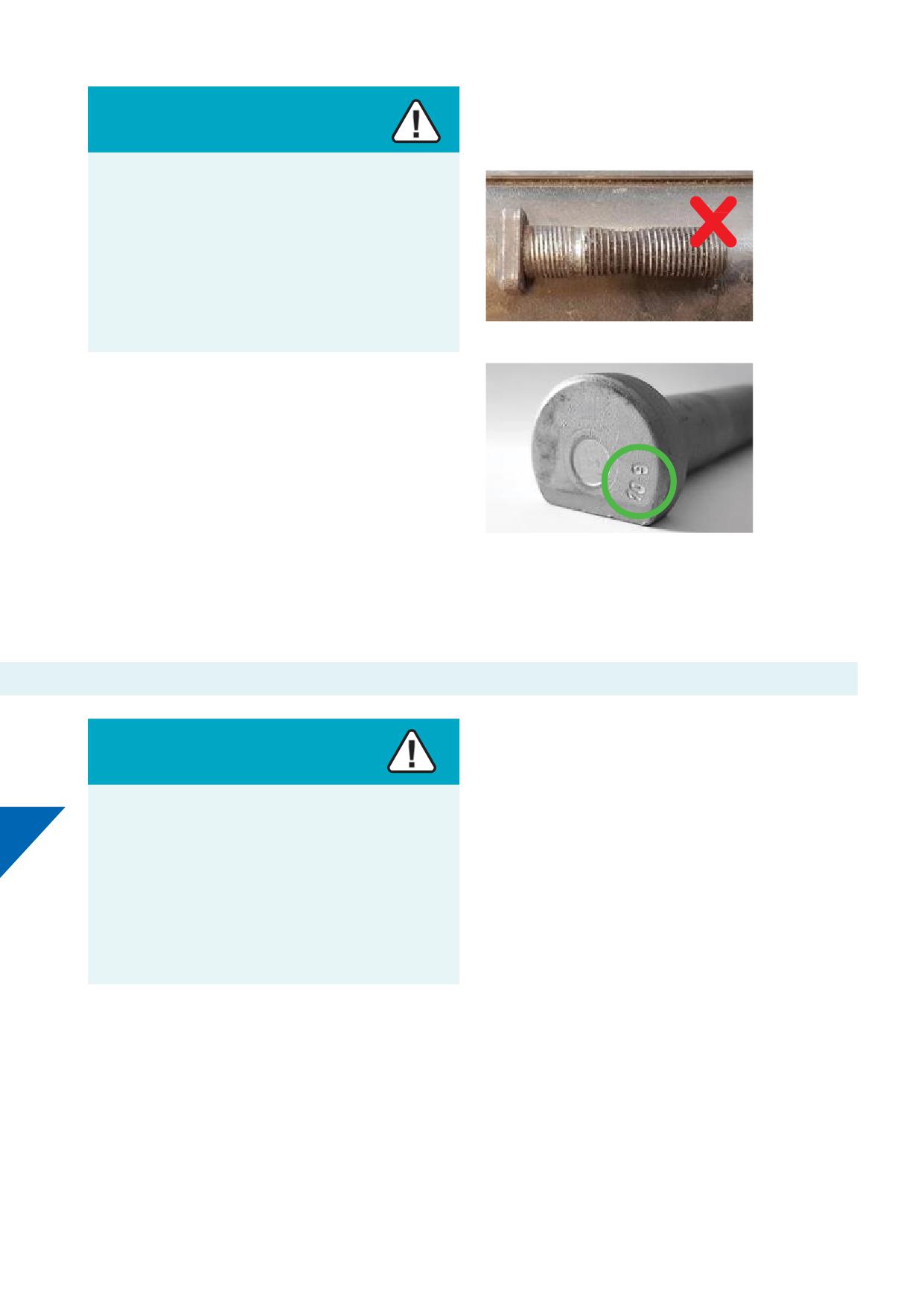
All wheel fastener hardware should be grade 8 or metric conversion
10.9. Follow the hardware manufacturers’ recommendations when
Warning
replacing studs.
The use of a wrong selection of wheels and hardware may
result in improper fi
of wheels.
Improper mounting of wheels may lead to separation of
wheels or loss of assemblies from the vehicle causing serious
injuries or death.
Follow the proper wheel installation and maintenance
practices as described in this Section.
Picture 11-19
11.b.iii. Wheel studs inspection
In service, stud dimensions and condition may change over time
due to environmental conditions, multiple re-installations, improper
torquing. and other factors.
Consult your vehicle, hub or stud manufacturer for regular
maintenance recommendations and stud replacement practices.
Picture 11-20
Check for and replace bent, broken, cracked or damaged studs.
When replacing broken studs, always replace the studs on each
side of the broken stud. If two or more studs are broken, replace all
the studs for that wheel position.
11.c. 2-piece hex head sleeved nuts for Alcoa® Wheels
NOTICE
Warning
• 1-piece nuts are not approved for use on any Alcoa® Wheels
application for medium - and heavy-duty vehicles.
• Only 2-piece nuts or 2-piece sleeved nuts with an integral freely
Use of chrome-plated nuts which have chrome plating on the
turning washer, designed for hub centring mounting systems,
11
surfaces which contact the wheel, can cause reduced and
must be used for fastening European type Alcoa® Wheels for
inconsistent wheel clamping.
medium- and heavy-duty vehicles.
• Regular 2-piece nuts that come with truck, bus or trailer axles
This condition can cause wheels to loosen and disengage
with steel wheels can also be used with Alcoa® Wheels with
from the vehicle, causing serious injury or death.
corresponding bolt hole diameters given the thread engagement
is suffi
See Section 11.a.
Never use nuts with chrome-plated contact surfaces. Use
• The following 2-piece hex head sleeved nut types are available
only recommended hardware on Alcoa® Wheels.
from Howmet Wheel Systems:
• M22 x 1.5 (Metric, Volvo 2005 >)
Design and specifi
of nuts, washers and studs used for
• M20 x 1.5
Alcoa® Wheels must comply with DIN standard 74361-3. Alcoa®
• M18 x 1.5
Wheels in Europe are commonly used with 2-piece hex head nuts
• 7/8”-11 BSF (Scania)
that have following threading:
•
7/8”-14 UNF (Volvo > 2004)
• Some vehicles come equipped with right-hand and left-hand
• M22 x 1.5
threads. These vehicles have on the right-side right-hand threads
• M20 x 1.5
and on the left-side left-hand threads. If an “R” or “L” is stamped
• M18 x 1.5
on the studs and nuts, it indicates right and left-hand threads
• 7/8” - 11 BSF
respectively.
•
7/8” - 14 UNF
54
Alcoa® Wheels 2-piece sleeved nuts:
Sleeved nut P/N*1
Replaces*1
Thread size
For
Sleeve
Application
GAX687632G
GAX578032
M22 x 1.5
Metric & Volvo 2005 >
Short
Single
N/A
GAX57803201*2
M22 x 1.5
Metric, LH thread
Short
Single
GAX687732G
GAX578132
M22 x 1.5
Metric & Volvo 2005 >
Long
Dual
N/A
GAX57813201*2
M22 x 1.5
Metric, LH thread
Long
Dual
GAX614230G
GAX614230
M20 x 1.5
Metric
Short
Single
GAX614330G
GAX614330
M20 x 1.5
Metric
Long
Dual
GAX542026G
GAX542026
M18 x 1.5
Metric
Short
Single
GAX542126G
GAX542126*3
M18 x 1.5
Metric
Long
Dual
GAX688032G
GAX578432
7/8”-11 BSF
Scania
Short
Single
GAX688132G
GAX578532
7/8”-11 BSF
Scania
Long
Dual
GAX687832G
GAX578232*3
7/8”-14 UNF
Volvo > 2004
Short
Single
GAX687932G
GAX578332
7/8”-14 UNF
Volvo > 2004
Long
Dual
Table 11-21
*1 At the moment of editing this manual the current portfolio and
NOTICE
stock were subject to change. Consult Howmet Wheel Systems
or authorized distributors of Alcoa® Wheels for updates and
Though sleeved nuts are designed to compensate standard stud
specifi
length suffi
a minimal stud standout i.e. thread engagement
is required. See Section 11.b.
*2 Available, as long as stocks last. The extension 01 on sleeved
nut part numbers indicate left-hand thread versions.
In case of mixed application, dualling steel wheels and Alcoa®
Wheels, short sleeve nuts can be used. See Sections 4.g., 11.b.ii. and
*3 Available, as long as stocks last.
12.c.
11
55
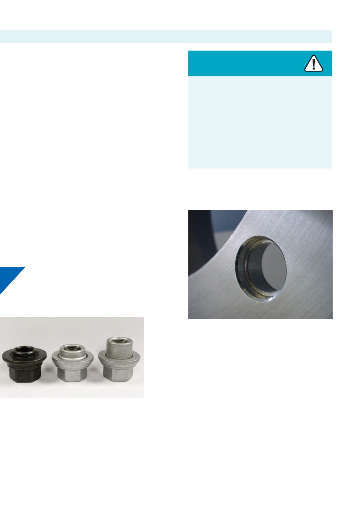
11.d. Mounting hardware for Alcoa® Wheels specifi
made for Volvo
Stud thread specifi
• During the 4Q of 2004 and 1Q of 2005 Volvo trucks and busses
Warning
changed stud thread specifi
from 7/8”-14 UNF to M22 x 1.5.
• When retrofi
wheels of Volvo vehicles, check the correct stud
DO NOT MIX Alcoa® Wheels specifi
made for Volvo and
thread specifi
Volvo OEM sleeved nuts with Alcoa® Wheels and sleeved nuts
• Sleeved nuts for retrofi
wheels of Volvo vehicles are available
for Alcoa® Wheels.
from Howmet Wheel Systems.
Mixing Alcoa® Wheels specifi
madefor Volvo / Volvo OEM
Mounting holes and sleeved nuts:
nuts and Alcoa® Wheels / sleeved nuts can result in incorrect
installation and separation of wheels from the vehicle during
1. Volvo vehicles may also be equipped with Alcoa® Wheels
operation, causing serious injury or death.
ex-works that have a diff
mounting system and
consequently diff
hardware. See picture 11-22.
Follow the proper wheel installation and maintenance
® Wheels specifi
made for Volvo have the Volvo logo/
2. Alcoa
practices as described in this Section.
name in the roll stamp of the wheel and have diff
Alcoa®
Wheels part numbers.
For more information consult the Volvo organization or contact
3. Alcoa® Wheels specifi
made for Volvo have diff
Howmet Wheel Systems.
mounting holes a.k.a. ‘dual hole’ i.e., each mounting hole comes
with two diff
diameters. See picture 11-23.
4. Alcoa® Wheels specifi
made for Volvo are installed with
longer studs and Volvo OEM sleeved nuts which diff from the
sleeved nuts available from Howmet Wheel Systems.
5. Alcoa® Wheels specifi
made for Volvo and Volvo hardware,
i.e., studs and nuts, are available from the Volvo organization
only.
11
Picture 11-23
Picture 11-22
Picture 11-22, from left to right:
• Volvo OEM sleeved nut for single and dual mounting: only
suitable for Volvo‘dual hole’ wheels
• Sleeved nut from HowmetWheel Systems for single mounting
• Sleeved nut from Howmet Wheel Systems for dual mounting
56
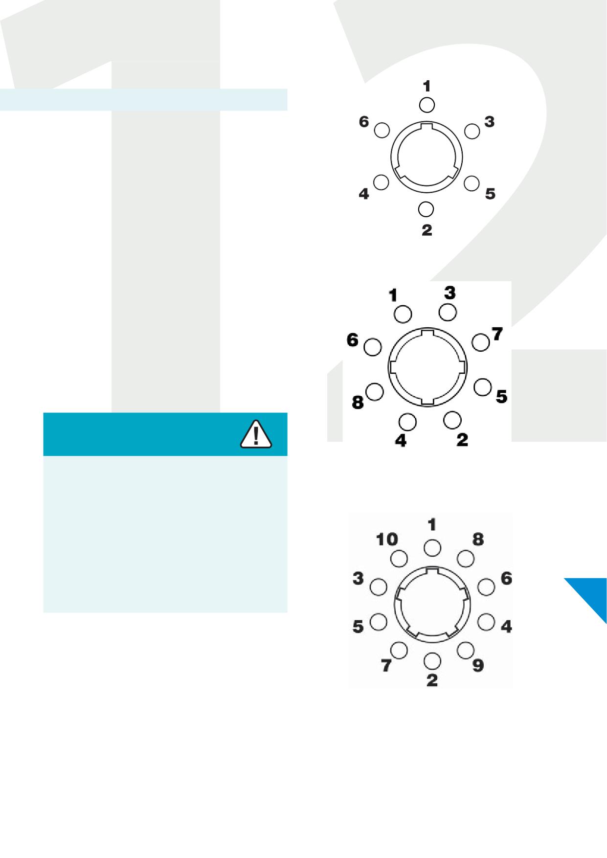
12. Wheel nuts
12.a. Tightening nuts
Studs with 2-piece fl
nuts M22 x1.5, M20 x 1.5, M18 x 1.5,
7/8" - 11 BSF or 7/8" - 14 UNF may be subject to diff
torque
requirements.
Inquire at the manufacturer of the vehicle or axle for proper torque
values or refer to the owner’s manual of the vehicle.
IMPORTANT
Check all parts, including wheels, studs, and nuts. Check for paint,
Graphic 12-1 - Six Stud
dirt, corrosion, or damage. Check mounting faces of wheels, hubs,
and drums.
Friction caused by paint, dirt, corrosion, or damage on nuts and/
or studs can absorb a substantial part of the torque applied on
the nut and cause a reduced clamping force.
Remove paint, dirt, and rust; replace damaged parts. Follow correct
tightening sequences and torque levels.
See Section 10.a.
Lubrication of nuts and studs:
Warning
Lubricants should not be applied to the nut’s washer i.e.
Graphic 12-2 - Eight Stud
nut-to-wheel contact surface. Application of excessive
lubricant to the threads of the stud and/or nut can cause
excessive torque beyond the yield point of the stud.
Over-torque can stretch studs causing them to fail. Failed
studs can cause the wheel to disengage from the vehicle,
causing serious injury or death.
Follow the proper wheel installation and maintenance
12
practices as described in this Section.
IMPORTANT
Lubricants must be completely removed from the nut’s washer i.e.
nut-to-wheel contact surfaceif applied accidentally.
Do not allow oil to contact mounting surfaces of the wheel, hub,
drum, or brakes. Do not use aerosol cans for lubrication of stud
Graphic 12-3 - Ten Stud
threads. See Section 10.a. See graphics 10-9 and 10-10.
Position one of the hub’s pilot tabs at the twelve o’clock position.
After positioning wheels on the pilot tabs, hand tighten all 2-piece
fl
nuts, then tighten to the recommended torque, following
the proper sequence shown for your wheel type. See graphics 12-1,
12-2 and 12-3.
57
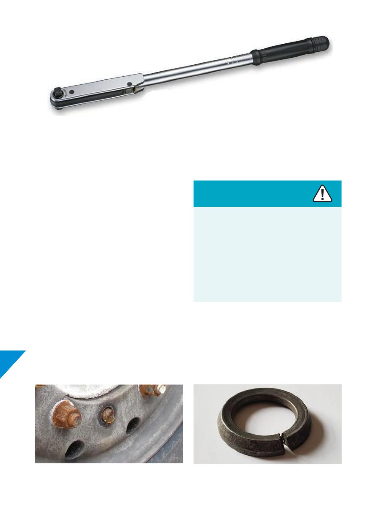
Picture 12-4
Torque wrench
After 8 - 80 kilometres or 5 - 50 miles of operation, torque should be
Under and over torque
recheckedunless vehicle/axlemanufacturer or your documented
fl
practices determine otherwise. Check torque frequently from
then on.
Warning
Nuts must be kept tight, and studs and nuts should be checked
frequently.
Under torqued nuts allow wheels to run loose, pounding out
(deforming) the bolt holes, fatiguing studs or losing nuts,
Impact wrenches, if used, should be carefully adjusted to apply
as well as cause cracks in the bolt hole area. Over torquing
torques within or below the limits recommended.
can stretch studs (See Picture 11-19) causing them to fail with
Tighten to the recommended torque with a calibrated torque
loss of clamping force.
wrench. See picture 12-4.
Torquing of nuts should be done in recommended sequences.
Both under and over torquing can lead to wheel
After each wheel mounting, nut torque should be checked with a
disengagement causing serious injury or death.
torque wrench. Nuts should be retorqued if necessary.
At tyre changes, nuts and studs should be inspected to be sure
Follow the proper wheel installation and maintenance
they are in good condition. If cracks, stripped or damaged threads
practices as described in this Section.
are found, remove these nuts from service. Check wheel studs
accordingly.
NOTICE
If nuts require frequent tightening, studs break frequently
(picture 12-5), wheel nut washers break (picture 12-6) or bolt
12
holes are pounding out, hardware and mounting practices
should be reviewed.
Picture 12-5
Picture 12-6
58
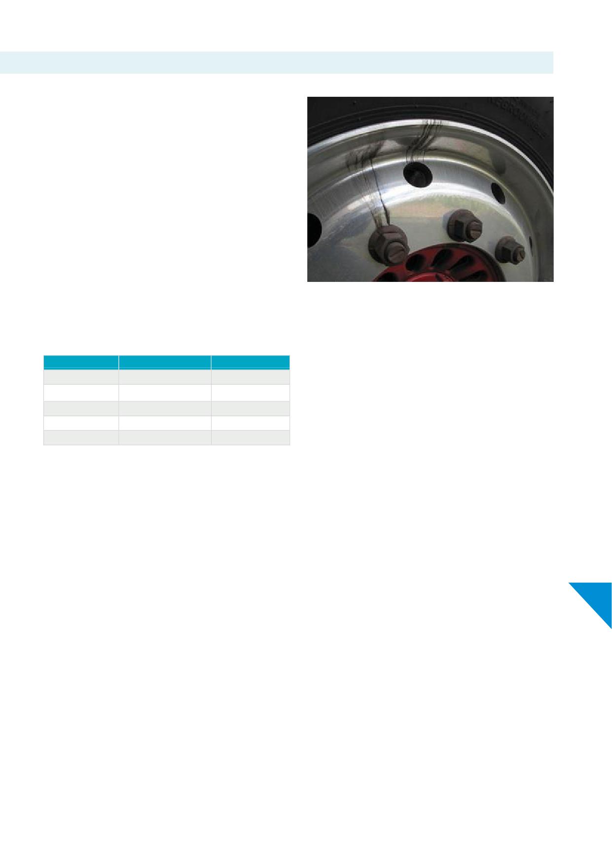
12.b. Keep wheel nuts tight
Nuts must be kept tight. Studs and nuts should be checked
frequently. At tyre changes nuts and studs should be inspected
to be sure they are in good condition. If nuts require frequent
tightening or studs break frequently, hardware and mounting
practices should be reviewed. Dirt streaks from nuts and / or vent
holes may indicate looseness. See picture 12-7.
For proper installation of 2-piece fl
nuts, two drops of motor oil
should be applied between the nut and integrated washer and two
drops to the fi two threads at the tip of each stud. See Section
10.a.
IMPORTANT
For proper nut torque, always refer to vehicle or axle
Picture 12-7
manufacturers’ recommendations, prior to using chart 12-8.
Hubpilotedwheels using 2-piece fl
nuts
(nuts with integrated washer):
For
Thread Size
Torque Level Nm
Metric
M18 x 1.5
340 - 400
Metric
M20 x 1.5
380 - 450
Metric *1
M22 x 1.5
610 - 675
Scania
7/8" - 11 BSF
540 - 660
Volvo *2
7/8" - 14 UNF
640 - 700
Chart 12-8
*1 Including Volvo from 2005
*2 Volvo up to 2004
For more details see Section 11.d. "Mounting hardware for Alcoa®
Wheels specifi
made for Volvo".
NOTICE
1. Tightening wheel nuts to their specifi torque is extremely
important. Under tightening can result in loose wheels, can
12
damage wheels, studs, and hubs, and may result in wheel loss.
Over tightening can damage studs, nuts and wheels and may
result in loose wheels also.
2. All torque wrenches, air impact wrenches and any other tools
should be calibrated periodically to ensure the proper torque is
applied.
3. Refer to vehicle or axle OEM for torque range for any hardware
that is noted above.
59
12.c. Dualling with steel wheels
When dualling steel wheels with Alcoa® Wheels, follow the steel
wheel manufacturers’ recommendations regarding the proper
torque and use of thread lubricants to mount the wheel. See
Warning
Section 4.g.
Using long sleeve nuts for mixed duals may cause a ‘bottom
IMPORTANT
out’ condition, see Section 11.b.ii.
On occasion Alcoa® Wheels are dualled with a steel inner wheel.
A ‘bottom out’ condition may lead to loss of wheels causing
When this application occurs, it is recommended that Discmates
serious injury or death.
for Alcoa® Wheels or nylon protection gasket is used, to prevent
galvanic corrosion.
Follow the proper wheel installation and maintenance
practices as described in Section 4.g.
In the event a steel inner wheel is used, extreme care must be
taken to properly seat it to the hub or drum before mounting the
outer aluminium wheel.
Selection of the correct hardware is required as providing
adequate thread length to secure the outer aluminium dual wheel
Warning
is critical to a safe assembly.
When mounting painted steel inner wheels with outer
Howmet Wheel Systems recommends the use of sleeved nuts for
aluminium wheels, be cautious of excessive paint build-up on
Alcoa® Wheels for this purpose:
the inner steel wheel.
• Short sleeve nuts can be used
• When using sleeved nuts, the minimal thread engagement
Excessive paint (> 90 μm / 3.5 mil) can reduce the clamping
required is indicated in Section 11.b.
force and allow the wheels to become loose. Wheels
separating from the vehicle can lead to serious injury or
death.
Follow the proper wheel installation and maintenance
practices as described in Section 10, 11 and 12.
12
6
1
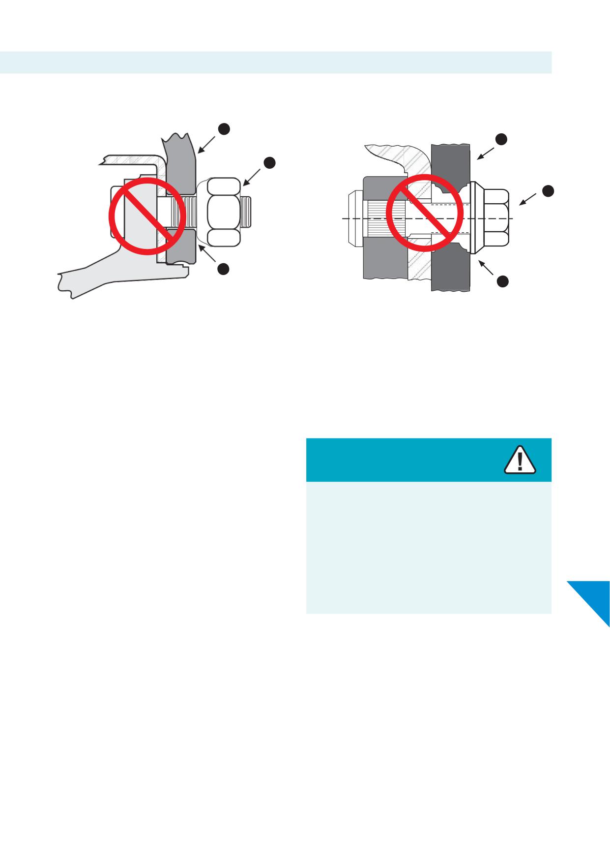
12.d. Incorrect assemblies
The following are examples of incorrect wheel assemblies.
1
1
2
2
3
3
Graphic 12-9
Graphic 12-10
1. Hub piloted aluminium wheel
1. Stud located, ball seat aluminium wheel
2. Ball seat or spherical nut
2.
2-piece fl
nut
3. Insuffi
contact area
3. Little (if any) contact area
• Do not use ball seat / spherical or conical seat nuts with hub
piloted wheels.
• Do not use standard 2-piece fl
nuts with stud located ball
Warning
seat / spherical or conical seat wheels.
• Do not use sleeved nuts using too small or too large bolt holes.
Using the wrong wheel nuts can cause loss of clamping force,
• Do not use standard 2-piece fl
nuts on wheels designed for
broken studs or cracked wheels.
use with sleeved nuts.
• Do not use Volvo OEM sleeved nuts on any other type of wheel.
Loss of clamping force, broken studs or cracked wheels can
• Do not use standard 2-piece fl
nuts on Alcoa® Wheels
lead to wheels separating from the vehicle causing serious
specifi
made for Volvo. See Section 11.d.
injury or death.
Use only hardware designed specifi
for each wheel type.
12
See Section 11 for proper hardware assemblies.
60
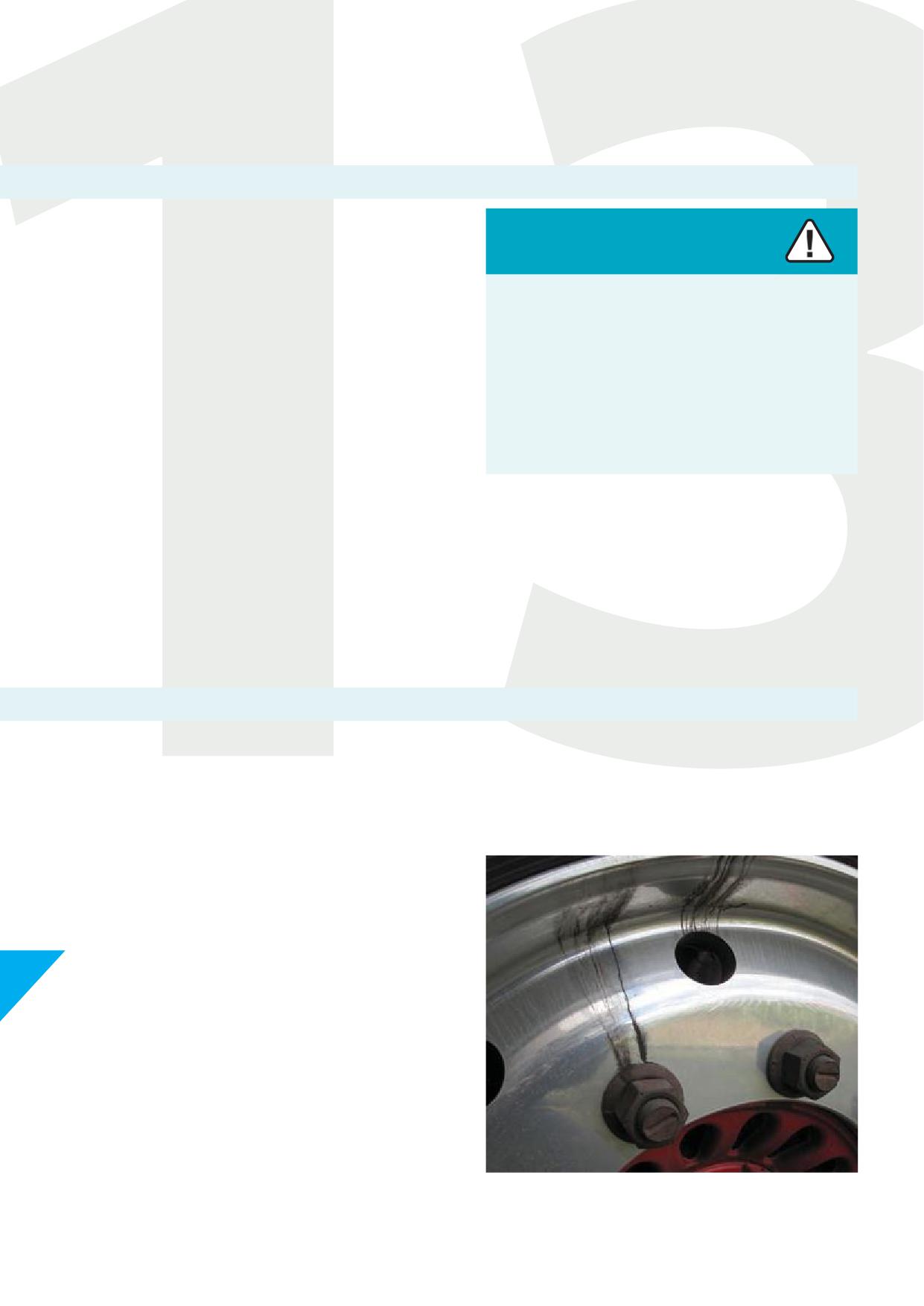
13. Wheels in service
13.a. Inspect thoroughly and frequently
Safe operation requires thorough examination of wheels and
attaching hardware, at frequent intervals, both on and off the
Warning
vehicle.
Failure to inspect wheels and hardware thoroughly and
Wheels that are in service need to be inspected at regular intervals
frequently may cause wheels to fail unexpectedly.
to assure proper and safe performance.
Unobserved wear, corrosion or cracks may result in a wheel
It is not always possible to predict the useful life of a wheel. Wheels
- or hardware failure or wheel loss causing serious injury or
will eventually wear out. But generally, older wheels and wheels
death.
operating in extreme conditions should be examined more
frequently for obvious signs that they should be removed from
Inspect wheels and hardware periodically for a safe
service.
operation of the vehicle.
Examine all exposed areas frequently. Clean wheels, inspect valves
and look for cracks, corrosion, wear, or other damage. Also check
the inner dualled wheel when the outer wheel is removed.
During tyre changes, thoroughly examine the entire wheel. Pay
particular attention to the rim contour, the surfaces of the rim, the
mounting fl
and mounting holes.
13.b. Hidden damage
Do not exceed maximum wheel load. Customer must compare
Check mounting holes for cracks, fretting, enlargement, and
OEM vehicle axle load ratings to maximum wheel load rating and
elongation which can occur if the nuts are not kept at proper
infl
pressure which is roll stamped onto the wheel. See Section
torque. Dirt streaks radiating from bolt holes and / or vent holes
4.d.
may indicate loose nuts. See Section 12.b.
Do not over-infl
Use the tyre - and wheel manufacturers’
recommended pressure, but under no circumstances exceed cold
infl
pressure listed by the tyre - and wheel manufacturer
which is on the tyre and wheel. Before mounting the tyre, perform
a wheel fi
check to ensure proper clearance from any
obstructions. See ‘Wheel fi
check’ Section 5.d.
13
Some forms of wheel damage can be hidden beneath the tyre, so
whenever a tyre is removed, thoroughly examine the complete
wheel. Remove all grease and road dirt. Use a wire brush or steel
wool to remove rubber from the bead seats.
Picture 13-1
62
Warning
Damaged tyres or wheels can lead to an explosive separation of tyres and wheels. An explosive separation can result in serious injury
or death.
Inspect tyres and wheels for damage before removing from vehicle.
If damage is found, tyres must be completely defl
before loosening wheel nuts. Remove damaged tyres or wheels from service.
13.c. Wheel alteration
Howmet Wheel Systems does not approve any form of alteration
to wheels except minor cosmetic buffi for appearance purposes.
Sanding and/or grinding is permitted to maintain the rim fl
of
Warning
the wheel. See Section 13.g.
Welding, brazing or otherwise heating any area of an Alcoa®
NOTICE
Wheel will weaken the wheel. Weakened or damaged wheels
can lead to an explosive separation of tyres and wheels or
Buffi
polishing, sanding, grinding or other kind of abrasive
wheel failure on the vehicle.
handling of Dura-Bright® surface treated wheels will remove the
Dura-Bright® surface treatment. For more information see Section
Explosive separations of tyres and wheels or wheel failure on
14.b.
the vehicle can cause serious injuries or death.
Wheels must not be altered by welding, brazing or other heat
Never attempt to weld, braze, or heat any surface of Alcoa®
application, e.g. powder coating in an attempt to repair or
Wheels.
straighten a wheel.
Use of adapter plates or bead-locks are not approved on Alcoa®
See Section 13.d. Heat Damage.
Wheels.
Wheels should not be painted, powder coated or otherwise coated
in any way that may interfere with the mounting surfaces.
Any wheel that shows signs of modifi
alteration or
13
adaptation should be removed from service and scrapped.
Thewheelidentifi
must be legible. Wheels should be taken
out of service if such identifi
is not legible or does not meet
regulatory requirements. See Section 4.d. Identifi
of Alcoa®
Wheels.
6
3
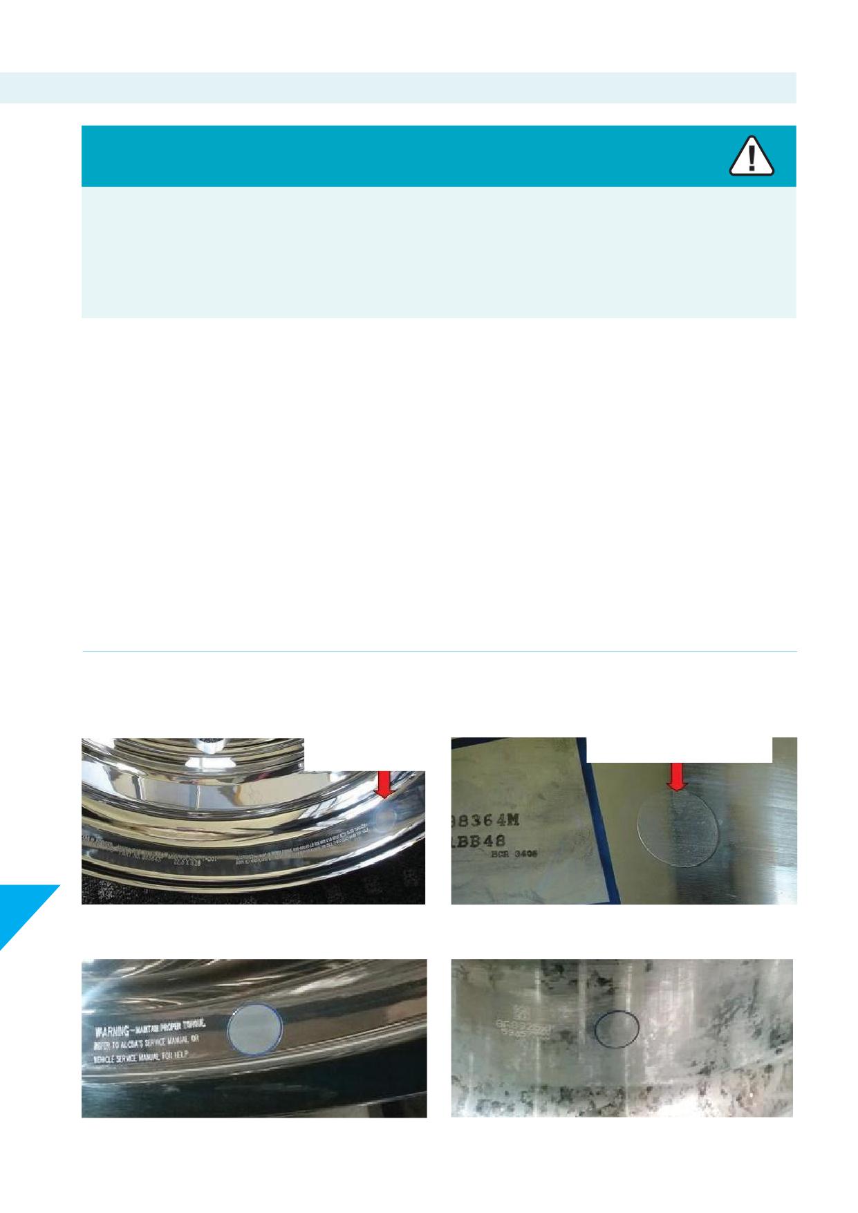
13.d. Heat damage
Warning
Excessive heat from fi brake malfunction, wheel bearing failure, tyre failure or other sources of heat may weaken the metal and
cause the tyre/wheel assembly to separate explosively.
An exploding tyre/wheel assembly can cause serious injury or death.
Immediately and permanently remove from service any wheel that has been exposed to excessive heat.
Wheels must be inspected if they have been exposed to excessive
A wheel may discolour from excessive heat. It can show a dull
heat before being returned to service. A wheel that has been
greyish colour and will not polish to a bright fi
as a typical wheel
exposed to excessive heat may appear charred or burned.
would.
A wheel that has been exposed to excessive heat may appear to be
Starting in January 2009 the new Alcoa® Wheels logo sticker on the
in good condition if it has been cleaned.
wheel may not show heat damage. Inspect all axle end components
for signs of exposure to excessive heat.
Do not use any wheel that has been overheated regardless of
appearance. Even if a wheel does not appear to be obviously
Check the brake lining of drum brakes or brake pads of disc brakes,
burned, inspect labels, tyre beads, brake components and the
Discmates for Alcoa® Wheels or nylon protection gaskets and tyre
Discmate for Alcoa® Wheels or nylon protection gasket for evidence
beads for heat damage. If one of these components show signs of
of charring, melting, blistering, or burning.
overheating, the entire assembly, including the wheel, should be
replaced, and removed from service permanently.
Any wheel run with a fl tyre longer than the time necessary to
immediately pull off the road, should be checked for excessive heat
damage.
Alcoa® Wheels manufactured from January 2009 and onwards have a 2.5 cmor 1 inch round clear heatindicator sticker located at the wheel
fl
next to the roll stamp along with a same sticker located on the tyre side drop well close to the valve hole as shown in pictures 13-2 to
13-5.
Heat Indicator
Heat Indicator
13
Picture 13-2 Heat Indicator at wheel fl
Picture 13-3 Heat indicator at wheel drop well
Picture 13-4 Heat indicator version 2 at wheel fl
Picture 13-5 Heat indicator version 2 at wheel drop well, close to serial
number and valve hole
64
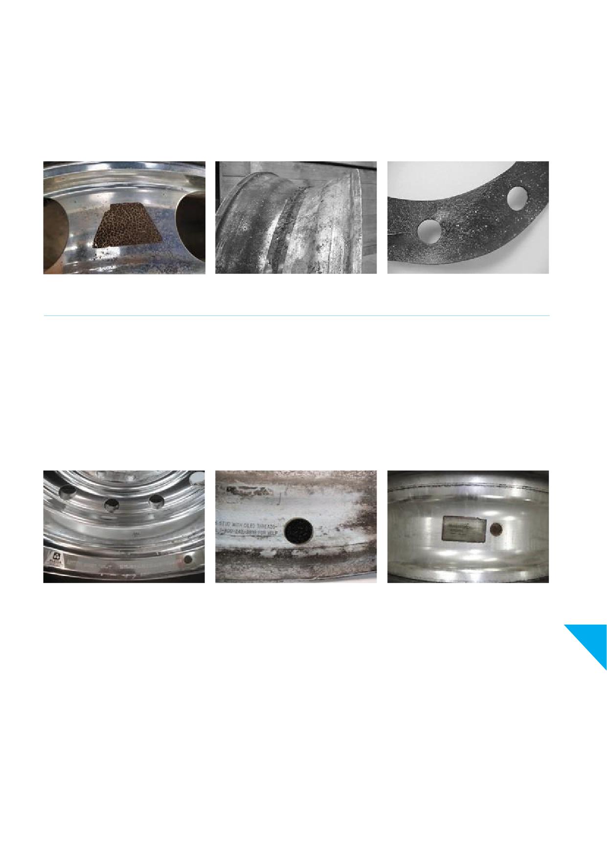
Wheels without heat indicator (prior to 2009):
A blistered, blackened or cracked looking logo decal on Alcoa®
Picture 13-6 Charred logo decal
Wheels may indicate that the wheel has been exposed to excessive
Picture 13-7 Discolouration of rim with charred rubber
heat. Discolouration of the wheel and/or a charred Discmate for
Picture 13-8 Charred Discmate for Alcoa® Wheels or other nylon
Alcoa® Wheels or other nylon protection gasket also may indicate
protection gasket
that the wheel has been exposed to excessive heat. See pictures
below.
Picture 13-6
Picture 13-7
Picture 13-8
Wheels with heat indicator (from 2009):
If either of these heat indicators show
Picture 13-9 Charred, discoloured heat indicator next to roll stamp
signs of blistering, charred, discoloured, or
Picture 13-10 Charred, discoloured heat indicator next to roll stamp (close up)
a cracked look, this may indicate that the
Picture 13-11 Charred, discoloured heat indicator in drop well inside the wheel
wheel has been exposed to excessive heat.
NOTE
Wheels with ANY discoloration of the heat indicator should have dimensional checks performed before returning the wheel to
service. See Section 13.e.
Picture 13-9
Picture 13-10
Picture 13-11
IMPORTANT
13
If any of the conditions as described and pictured on this page are
observed, remove the wheel from service immediately and perform
dimensional checks per Section 13.e.
This includes any heat damage to the tyre, discolouration to the
wheel and/or brake parts, as well as any burnt or charred labels.
Do not attempt to mount and infl a tyre on a wheel that
shows conditions as described and pictured in this Section, until
dimensional checks are performed per Section 13.e.
65
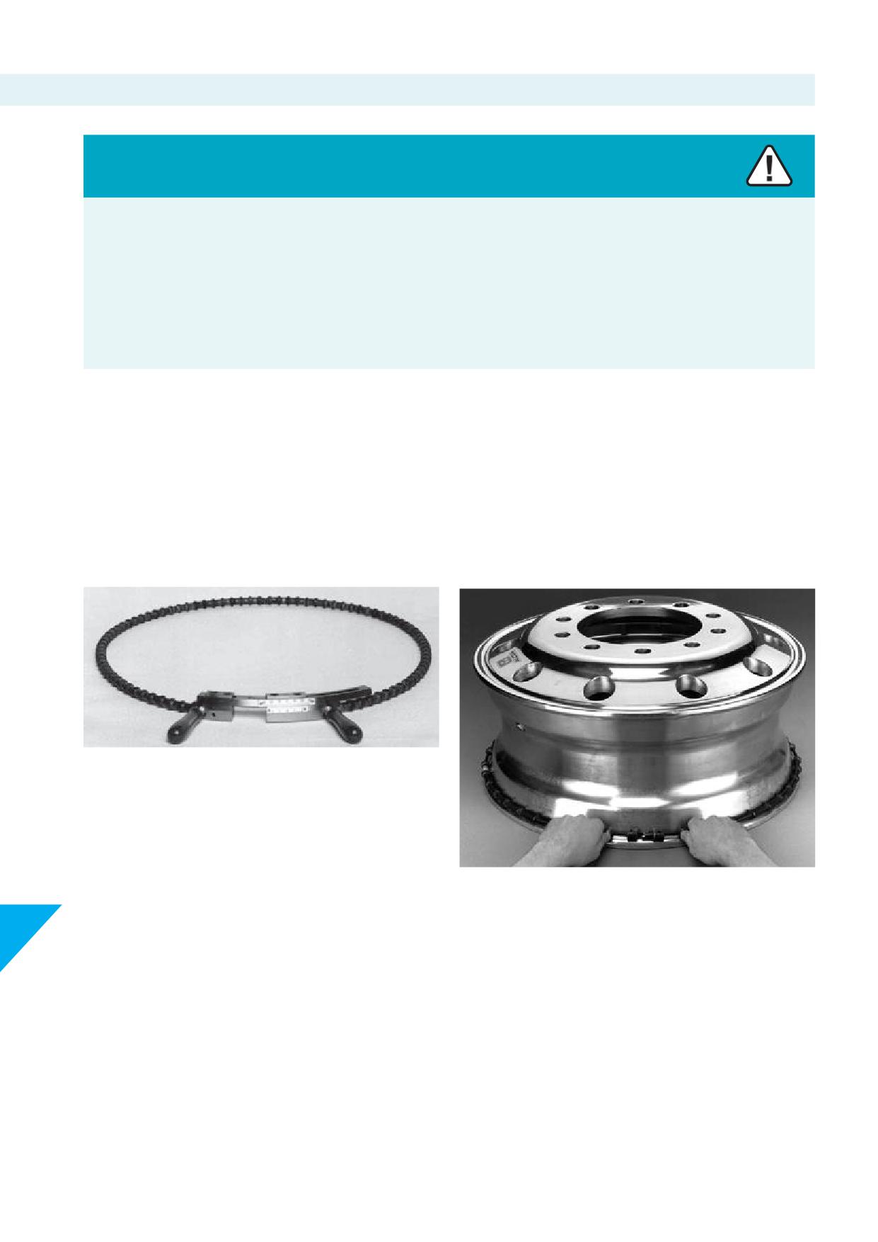
13.e. Dimension checks
Warning
Wheels that have run fl been subjected to high pressure tyre and rim separation, excessive heat damage or have other physical
damage, may no longer have the correct dimensions and contours to retain the tyre beads while under pressure.
Rims that lack proper dimension and contour can lead to explosive separation of the tyre and rim, causing serious injury or death.
Any wheel that has been in service must be inspected prior to mounting a tyre. Immediately and permanently remove from service
any wheel that has been exposed to high pressure, tyre and rim separation or excessive heat.
IMPORTANT
Follow dimension check procedures described in this Section during each wheel inspection.
13.e.i. Dimension checks
Best inspection method: with a wheel rim ball tape
Picture 13-12
Picture 13-12 shows an example of a wheel rim ball tape.
Measure the circumference of the bead seat on the open side with
a ball tape. See picture 13-13.
Picture 13-13
The circumference of the bead seat on the open side of the wheel
should be checked at each tyre change. The open side is the side
13
opposite the disc face.
In the case of centre fl
wide base wheels, or wheels with
off
(or insets) less than 76 mm or 3 inches, both bead seats
should be checked.
All wheels should be inspected prior to mounting.
66
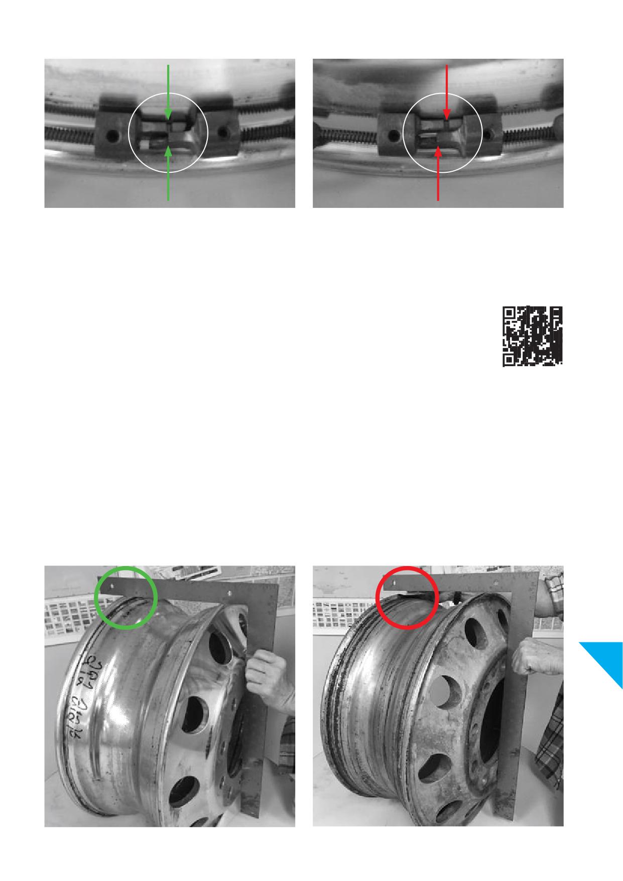
Picture 13-14
Picture 13-15
Correct dimension
Reject wheel from service
If the circumference of the bead seat does not match the required
Wheel rim ball tapes or disk tapes used for measuring wheel
dimension as indicated by the wheel rim ball tape, immediately and
circumference can be purchased from:
permanently remove the wheel from service and scrap.
The Tire and Rim Association
4000 Embassy Parkway, Suite 390
Akron, OH 44333
T +1 330 666 8121
E tra@us-tra.org
13.e.ii. Dimension checks
2nd best inspection method: if a ball tape is unavailable, use a carpenter square
ACCEPTABLE
UNACCEPTABLE
Picture 13-16 shows carpenter square even on both rim fl
Picture 13-17 shows an undersized wheel diameter where a credit
card (approx. 0,76 mm or 0.030 inches) can be placed easily
between the square and the wheel fl
13
67
Picture 13-16
Picture 13-17
68
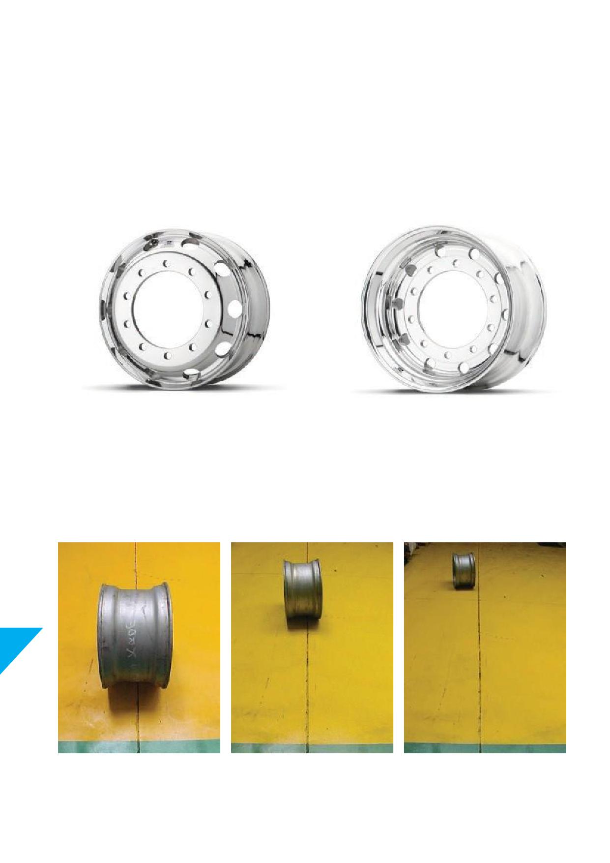
THIS INSPECTION METHOD ONLY APPLIES TO DUAL OR DISC FACED WHEELS.
Check all wheels at each tyre change for proper contour of the
If a distance greater than the thickness of a credit card (0,76 mm or
open side of the rim.
0.030in. feeler gauge) appears between the short leg and the rim
1. Place the long leg of a carpenter square across and against the
fl
the wheel should be permanently removed from service
centre of the disc side of the wheel.
and scrapped.
2. Extend the short leg across both rim fl
of the wheel as
shown in pictures 13-16 and 13-17.
3. Repeat this process at four equidistant points around the
wheel. The short leg should touch both rim fl
at each
point.
Picture 13-18
Picture 13-19
Wheel that can be mounted in dual position
Wheel that can be mounted single only
13.e.iii. Dimension checks
3rd best inspection method: rolling wheel as described below
13
Picture 13-20
Picture 13-21
Picture 13-22
69
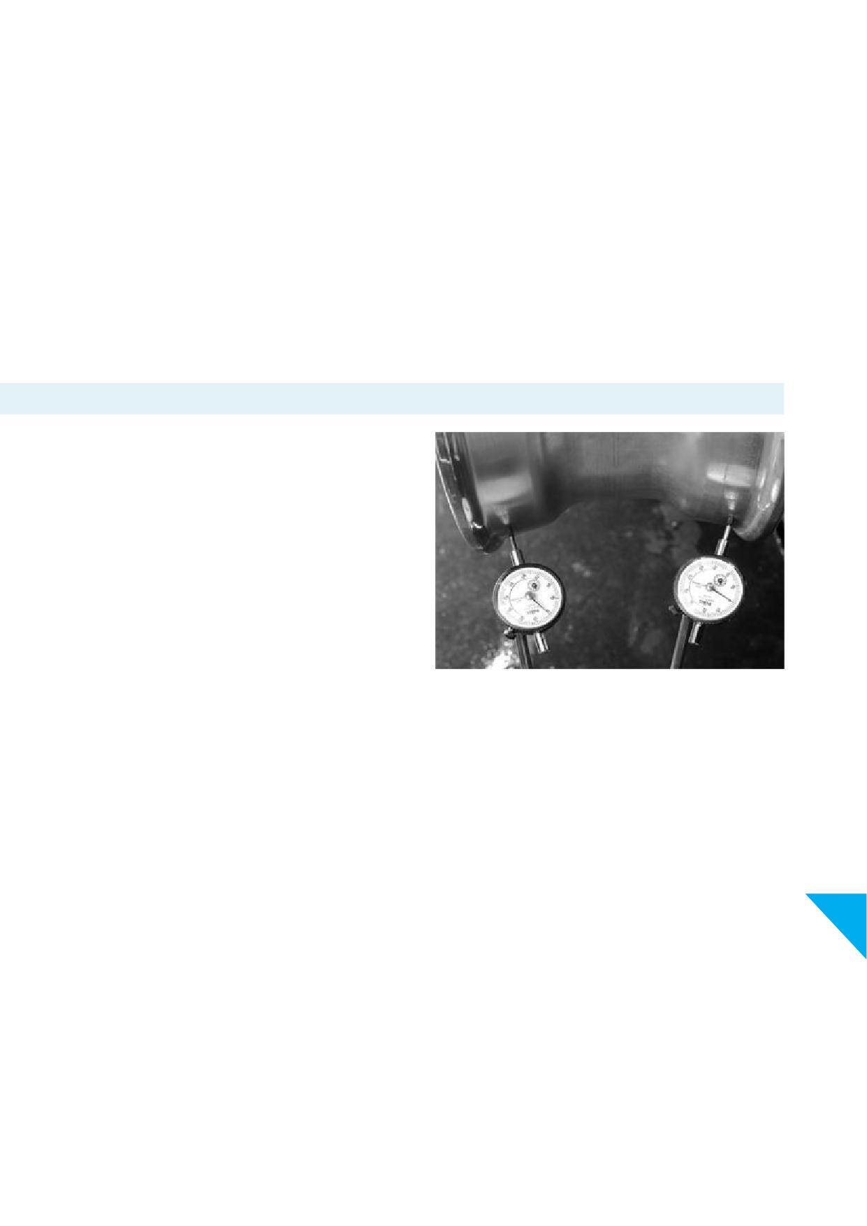
If a ball tape or carpenter square is unavailable, roll the wheel,
without a tyre, a minimum of 3 metres or 10 feet over a smooth,
fl
level, clean surface, such as asphalt or concrete pavement.
Any deviation from rolling in a straight line is an indication of a
potential lack of proper dimension and contour. See pictures 13-20,
13-21 and 13-22. Remove the wheel from service until it can be
properly checked with a wheel rim ball tape.
If you do not fully understand any of these inspection methods as
described in this Section contact Howmet Wheel Systems.
13.f. Tyre wear or vibrations
If you experience irregular tyre wear or vibrations it may be helpful
to check radial run out. Remove the wheel from the vehicle, defl
and remove the tyre. See Section 8 for defl
and demounting
tubeless tyres and Section 7.c. forinfl
and bead seating check.
Remount the wheel on the vehicle without the tyre. Be sure to
follow proper mounting procedures to assure the wheel is well
centred on the hub. Place a dial indicator as illustrated in picture
13-23 to trace the bead seats of the wheel. Rotate the wheel noting
the amount of variation shown on the dial indicator. Alcoa® Wheels
should be tested for radial run out only at the bead seat surface. A
total reading of 0.75 mm or 0.03 inch or less is acceptable.
Irregular tyre wear can also be caused by improperly seated tyres.
Picture 13-23
Inspect the tyre for proper seating on the wheel. The tyre beads
may not be seated properly. If so, remove the wheel from the
vehicle, defl
the tyre and break the bead seats. See Section 8
Defl
and demounting tubeless tyres.
Adequately lubricate the bead seats and properly reseat the tyre
beads. See Section 8.b.iii. Lubricants and Section 7.c. Infl
and
bead seating check.
Re-infl
the tyre wheel assembly in a safety restraint or tyre cage.
See Section 7.c. Infl
and bead seating check.
NOTICE
13
Run-out tolerance or total indicator reading may be 0.75 mm or
0.03 inch for a new wheel.
If the wheel has been in use it may already have been exposed to
impacts. Some deformation may occur.
70
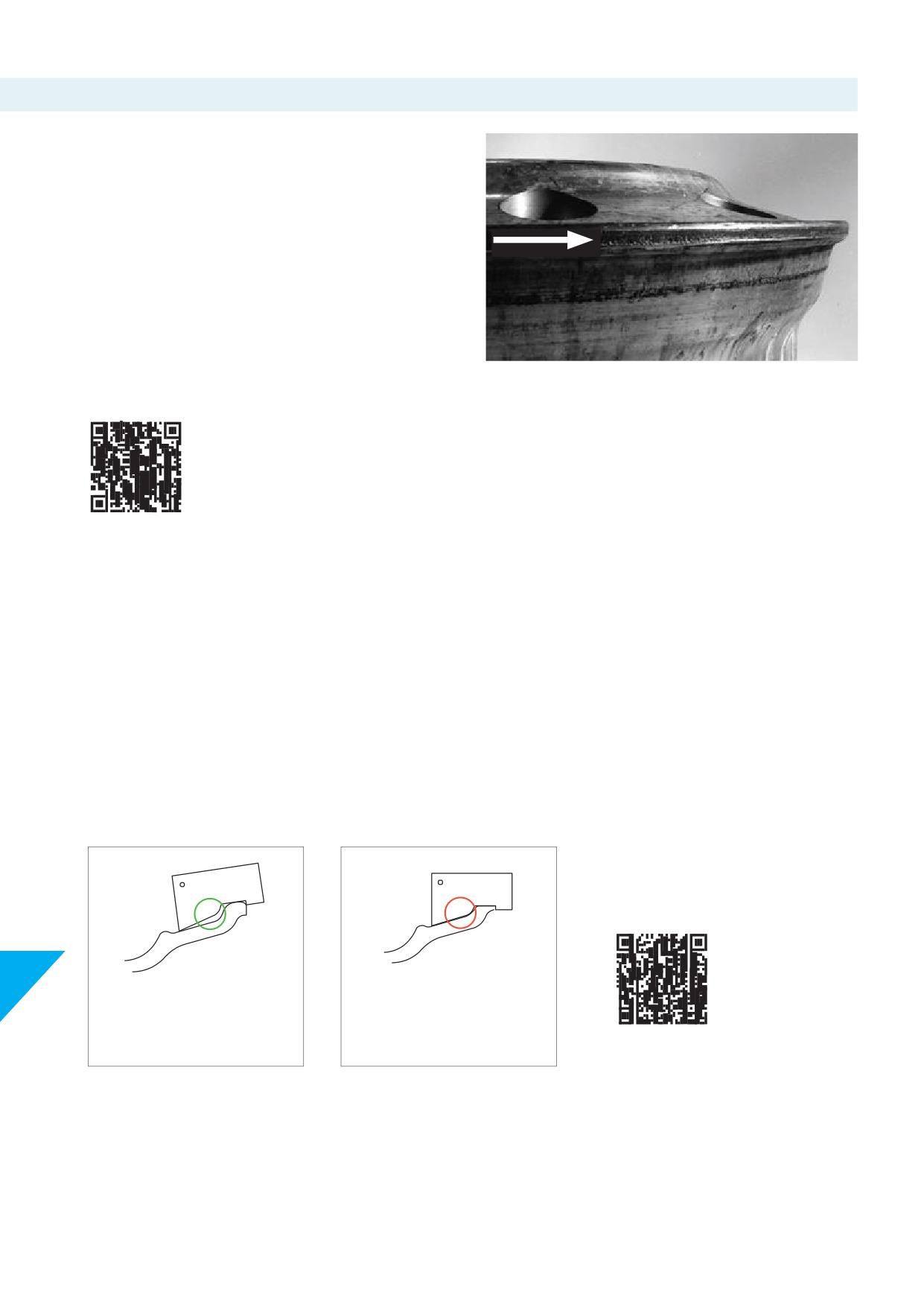
13.g. Rim fl
wear
Rim fl
wear is not a warrantable condition. Only Dura-Flange®
wheels have a 24-month warranty period against wear which
creates a sharp edge that would require maintenance.
Irregular wear on the surface of the rim fl
is caused by
abrasion from the tyre. Rim fl
wear happens most often in
applications with heavy or shifting loads.
If excessive rim fl
wear is observed, consider using
Dura-Flange® Alcoa® Wheels. These wheels have been specially
treated to signifi
reduce rim fl
wear.
Picture 13-24
For information consult QR code
Remove wheels from service when rim fl
wear is excessive.
Excessive wear can be determined using a Howmet Wheel Systems
approved wear gauge and procedures detailed under Section
13.g.ii.
If rim fl
wear creates sharp edges and/or cuts the tyre, see ‘Rim
fl
maintenance / edge removal procedures’ detailed under
Section 13.g.iii.
13.g.i. Alcoa® Wheels rim fl
wear gauge instructions
These gauges are to be used for Alcoa® Wheels and rim fl
wear only. They are not a bead seat angle or diameter tool. For steel wheels
and other aluminium wheels other regulations may apply.
Alcoa® Wheels rim fl
wear gauges are
Wear gauge
Wear gauge
available from authorized distributors
of Alcoa® Wheels.
Rim fl
Rim fl
13
Daylight in this area indicates
No daylight in this area
acceptable fl
indicates excessive wear
Graphic 13-25
Graphic 13-26
Rim acceptable
Rim NOT acceptable
70
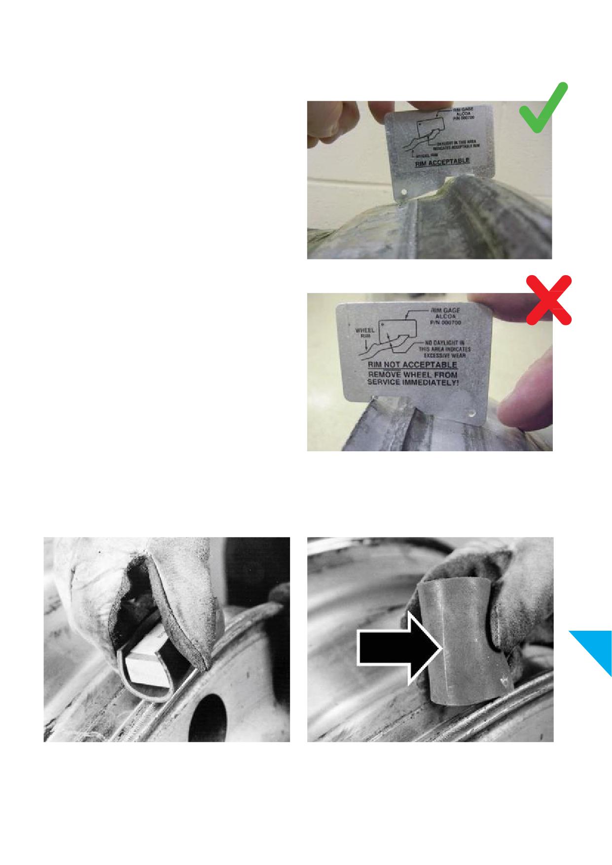
13.g.ii. Determining rim fl
wear
STEP1
Removethe tyre/wheel assembly from the vehicle and remove
the tyre from the wheel according to Section 8, Defl
and
demountingtubelesstyresfromAlcoa® Wheels.
STEP2
After the tyre is removed from the wheel, verify if the circumference
of the bead seat on the open side is acceptable. See Section 13.e.
Dimension checks.
Picture 13-27 SERVICEABLE
Check the rim fl
with the Rim Flange Wear Gauge for Alcoa®
Wheels to determine if the wheel must be removed from service for
excessive rim fl
wear. See pictures 13-27 and 13-28.
See Alcoa® Wheels rim fl
wear gauge instructions, Section
13.g.i. and preceeding graphics to make this determination.
Rim Flange Wear Gauges are available from authorized distributors
of Alcoa® Wheels
Picture 13-28 NOT SERVICEABLE
STEP3
If the rim fl
wear gauge shows the wheel is serviceable, examine the wheel fl
edge for sharpness by using a rubber sharpness
gauge. These gauges are made by attaching a section of tyre side wall or a suitable piece of rubber to a block of wood.
13
Picture 13-29
Picture 13-30
A rubber sharpness gauge or a suitable piece of rubber attached to
Run the sharpnessindicator gauge along the wheel at the area
a block of wood.
of the wear to determine if this wear is sharp enough to cut or
damage the rubber on the sharpness indicator.
71
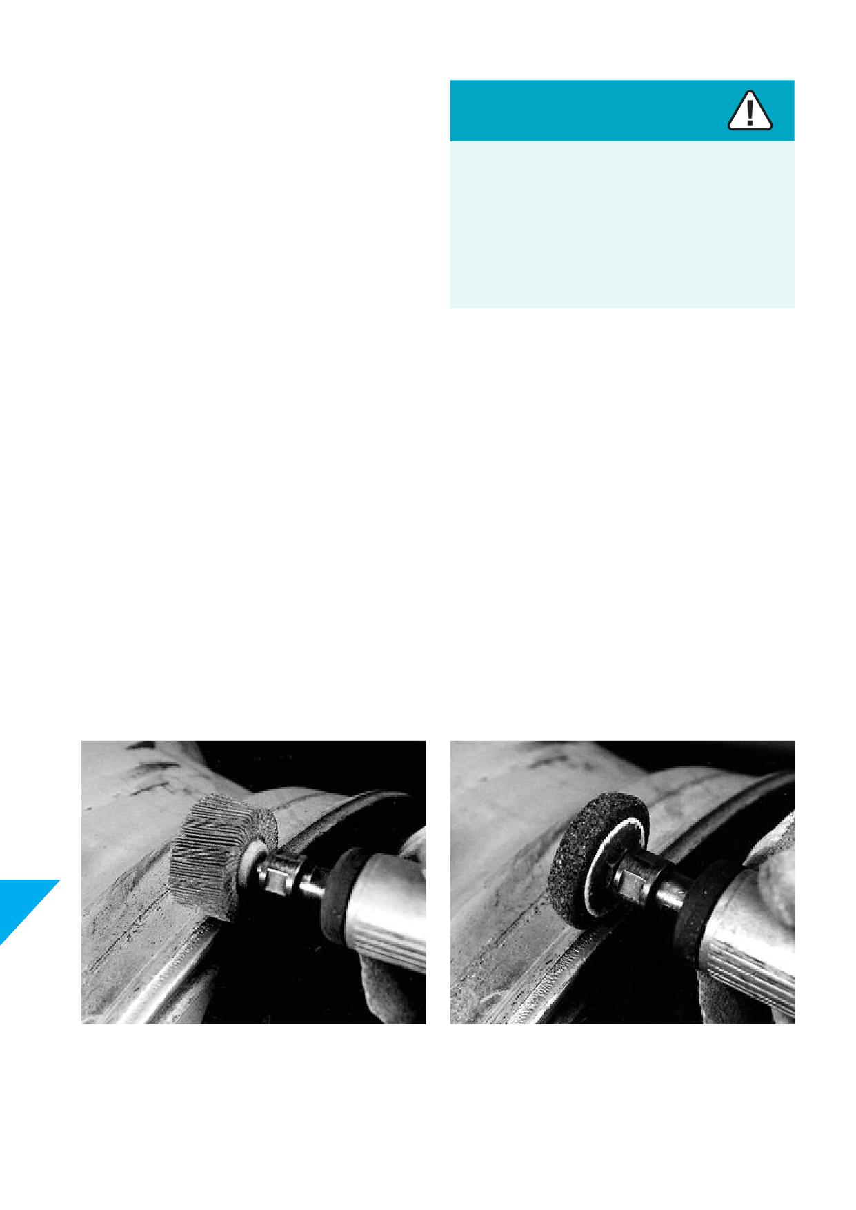
By running the sharpness indicator gauge along the wheel in the
area of the wear, determine if this wear is sharp enough to cut or
damage the rubber on the sharpness indicator. If the rubber is cut,
Caution
then follow the edge removal instructions as describedin Section
13.g.iii.
Do not run unprotected hands or fi
across worn rim
fl
areas of used wheels.
NOTICE
Examine the tyre for cuts in the bead areas and side walls. If
Worn rim fl
areas are sharp and can cut hands or
no damage occurred to these areas, return the tyre to service.
fi
Cut tyres should be removed from service. The tyre should be
inspected at this time for any other damage and be treated per
Always wear gloves when handling used wheels or when
normal tyre procedures recommended by the tyre manufacturer.
checking for edge sharpness of rim fl
NOTICE
Check the wheel at every tyre change or minimum ONCE PER YEAR
for rim fl
wear and any sharp edges. Following this practice, it
will signifi
reduce the possibility of a rim fl
cutting into
the tyre.
If a rim fl
cuts, or appears close to being sharp enough to
cut, the rubber on the sharpness indicator gauge, the edge can be
removed as per the edge removal procedures in following pages.
If the rubber is not cut, then the wheel can be returned to service
without further work for rim fl
wear.
13.g.iii. Rim fl
maintenance/edge removalprocedures
There are many tools available to remove a sharp edge on the wheel caused by rim fl
wear. Here are some examples of commonly
used tools:
13
Picture 13-31 Air or electric power sander
Picture 13-32 Air or electric power grinder
A very quick and eff
method of removing the sharp edge.
Another quick and eff
method of removing the sharp edge
Operators should use all care to keep a uniform rim fl
when
caused by rim fl
wear. Be careful as grinding pads may “gum
using these tools.
up” from the aluminium that is removed. Avoid gouging the wheel.
72
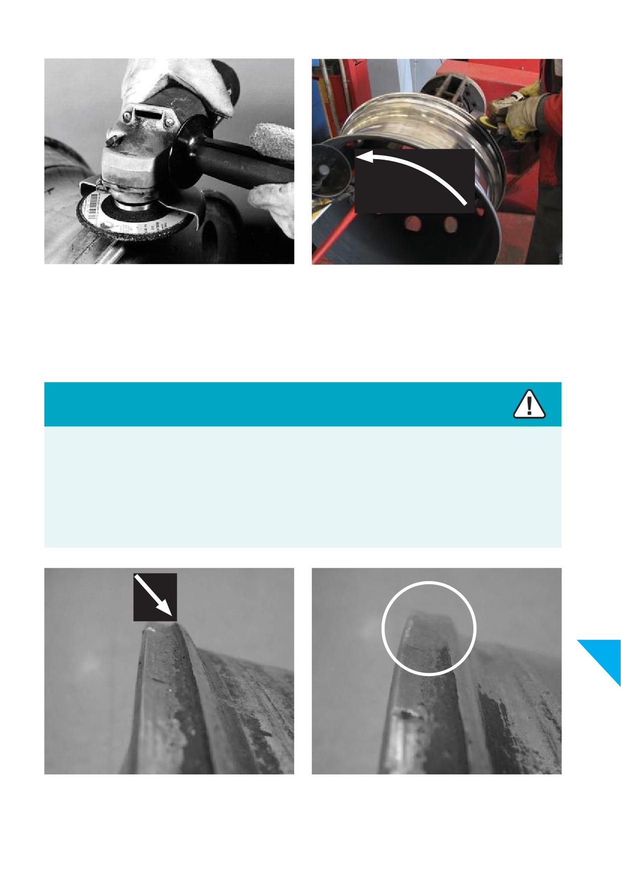
Picture 13-33 Angle die grinder
Picture 13-34 Angle die grinder, tips
Using with a sanding wheel, cutting stone, or grinding tool, this is a
After removing the tyre from the wheel, leave the wheel on the
version of an electric grinder. This tool is very quick and eff
as
tyre changer. Let the wheel rotate slowly and use the die grinder
well. Remove metal as uniformly as possible and do not gouge the
to remove the sharp edge from the wheel rim fl
Remove the
wheel.
metal as uniformly as possible, without swinging, or adding force to,
the angle die grinder. Do not gouge the wheel.
Caution
Removing sharp edges with hand or power tools produces metal fi
and sparks. Power tools may have parts that are sharp. Some
power tools produce excessive noise and may heat up during use.
Metal fi
can be sharp and, when projected by the action of power tools, can cause serious skin or eye damage. Excessive noise
from power tools can harm hearing. Sharp parts can produce cuts and hot surfaces can cause burns.
Always wear appropriate safety gear such as protective eye wear, gloves, protective clothing, and hearing protection when using hand
or power tools.
13
Picture 13-35 Sharp edge before removal
Picture 13-36 Sharp edge removed
73
STEP4
Pictures 13-35 and 13-36 show the result of removing the edge.
With whatever tool is selected, work the tool around the wheel’s
Warning
circumference, removing only enough material to eliminate the
sharp edge. This should only be a small amount of metal.
Welding or brazing the rim fl
or any area of an Alcoa®
Wheel will weaken the wheel. Weakened or damaged wheels
Perform this work on both fl
if there is evidence of sharpness.
can lead to an explosive separation of tyres and wheels or
Make sure the edge removal is as uniform as possible. Avoid
wheel failure on the vehicle.
gouging the wheel.
Explosive separations of tyres and wheels or wheel failure on
the vehicle can cause serious injury or death.
STEP5
After the sharp edge is removed, run the sharpness indicator gauge
Never attempt to weld or braze any surface of an Alcoa®
(Section 13.g.ii. STEP 3) along the area of edge removal to check for
Wheel.
any remaining sharpness.
If the rubber is still cut, perform the previous steps again to remove
the sharp edge. Always remove the minimum amount of material
necessary to eliminate the sharp edge.
Warning
Returning wheels to service with inadequate fl
height as
STEP6
determined by the Rim Flange Wear Gauge for Alcoa® Wheels
Check the rim fl
height with the Rim Flange Wear Gauge for
can lead to an explosive separation of tyres and wheels.
Alcoa® Wheels to make sure there is adequate height remaining to
safely support the tyre. Section 13.g.ii. STEP 2 shows how the gauge
Explosive separations of tyres and wheels can cause serious
is to be used. Move the gauge all around the wheel’s circumference
injury or death.
and make sure that no area of the fl
is below what the gauge
indicates as acceptable. If the entire wheel fl
is within the limits
Wheels with a fl height that falls below the Rim Flange
of the rim fl
wear gauge, the wheel may be returned to service.
Wear Gauge have inadequate rim fl height to support
the tyre on the rim. Immediately and permanently remove
any wheel from service that has inadequate rim fl
STEP7
height.
Always inspect the wheel for any other conditions that would
warrant removal from service. See all paragraphs of this Section.
IMPORTANT
Always follow safe mounting procedures as recommended in this
Warning
manual and use an approved safety restraint or tyre cage when
infl
a tyre/wheel assembly.
Excessive heat from fi brake malfunction, wheel bearing
failure, tyre failure or other sources of heat may weaken
Rim fl
wear could dictate the use of “stick-on” or adhesive
the metal and cause the tyre/wheel assemblies to separate
balancing weights if there is inadequate rim fl
to properly hold
explosively.
a clip-on style balancing weight.
13
Exploding tyre/wheel assembly can cause serious injury or
death.
NOTICE
Use Alcoa® Wheels Rim Flange Wear Gauge for Alcoa® Wheels only.
Immediately and permanently remove from service any
wheel that has been exposed to excessive heat.
7
4
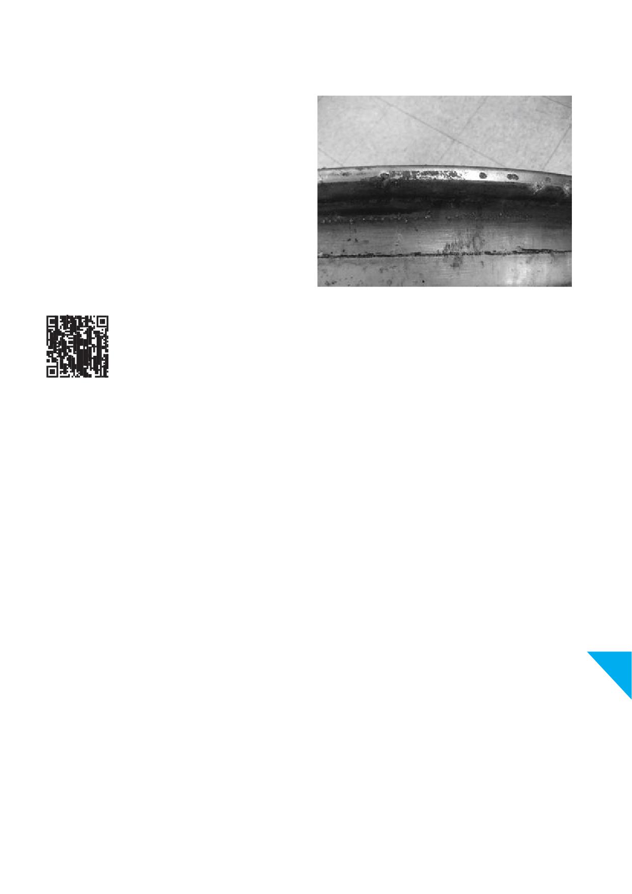
13.g.iv. Dura-Flange®
If excessive rim fl
wear is frequently observed in your
operation, consider using Dura-Flange® Alcoa® Wheels. These
wheels are specially treated to signifi
reduce rim fl
wear.
Only Dura-Flange® wheels have a warranty on rim fl
wear.
Dura-Flange® has a 24-month warranty against wear which creates
a sharp edge that would require maintenance as per foregoing
Section 13.g.iii. Rim fl
maintenance / edge removal procedures.
NOTICE
Minor wear or minor pitting is not a warrantable condition.
Edgere-conditioning cannotbeperformedonDura-Flange®Alcoa®
Wheels including those methods described in Section 13.g.iii. Rim
fl
maintenance / edge removal procedures.
Picture 13-37 Acceptable wear and pitting
13
75
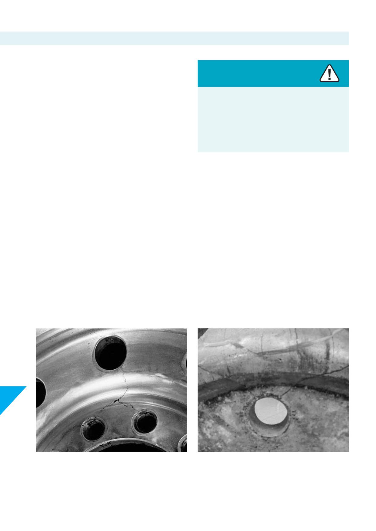
13.h. Cracked or damaged wheel checks
Visually inspect wheels for cracks or damage. Remove wheels
from service with known or suspected damage. See the following
Sections for reference.
Warning
Cracked or damaged wheels may fail or come off the vehicle.
Wheels that fail or come off the vehicle while it is moving can
cause serious injury or death.
Immediately and permanently remove cracked or damaged
wheels from service.
13.h.i. Mounting area
Cracks in the mounting - or disc area are usually caused by
Pictures of examples below show cracks starting in the disc area.
improper installation (see Sections 10 and 11), excessive loading or
Probable causes are:
insuffi
mounting fl
support (see Section 13.h.i.) by the hub
• Incorrect attachment parts or mounting hardware, see Section
or brake drum. Remove the wheel from service immediately and
11 (Picture 13-38)
permanently.
• Insuffi
torque, see Sections 10 and 12 (Picture 13-39)
• Undersized diameter of wheel support surface (Picture 13-40)
The indication may be caused by, one or a combination of following
• Presence of paint, dirt, and corrosion at mating faces of wheel
conditions:
and hub, when installing (Picture 13-41)
• Overloading, uneven distribution of load on axles and / or
• Support surface not fl (Picture 13-42)
• Improper fi
lack of lubrication hardware and/or
• Insuffi
maintenance (cleaning mating faces), and/or
• Application / use of non-spec / non-genuine hardware
13
Picture 13-38
Picture 13-39
76
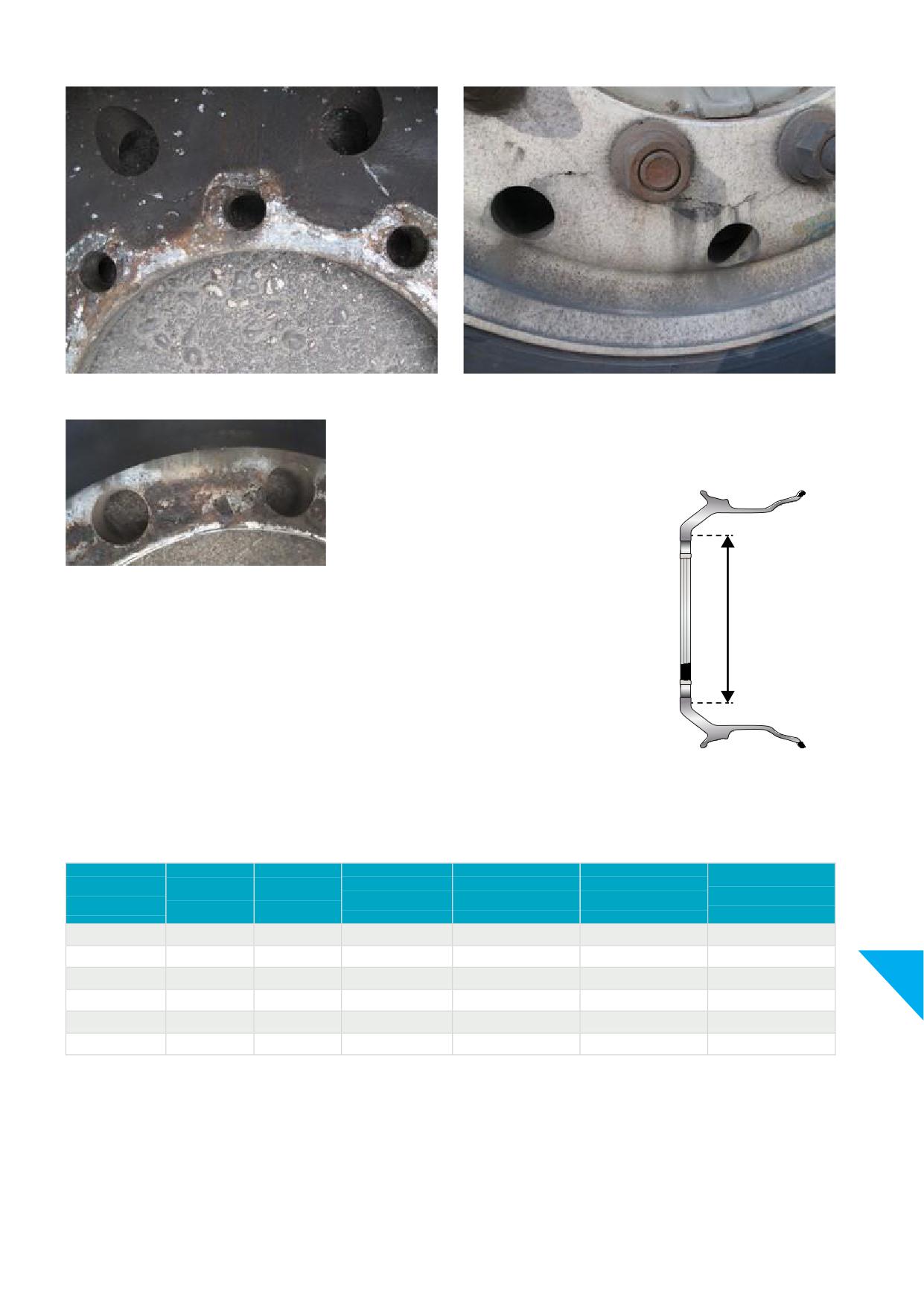
Picture 13-40
Picture 13-41
Inspect the hub / drum contact area of the wheel disc thoroughly for cracks or
other damage. If any crack is observed in this area remove the wheel from service
immediately and permanently.
The hub / drum wheel surface contact should be
Picture 13-42
smooth and fl within the entire wheel support
diameter as per recommendation in Chart 13-44
to properly support the wheel disc.
Backup
Graphic 13-43
Recommended backup diameter (See Graphic 13-43) applicable to hub pilot mounting type Alcoa® Wheels:
Howmet
Bolt circle Ø
ISO 4107
SAE J694
DIN 74361-3
Nr of bolts
Thread size
recommended
mm
Backup Ø mm
Backup Ø mm
Backup Ø mm
backup Ø mm
205
6
M18 x 1.5
250 - 251
245 - 250
250
245 - 251
245
6
M18 x 1.5
290 - 291
290
285 - 291
13
275
8
M20 x 1.5
320 - 321
315 - 320
320
315 - 321
275
8
M22 x 1.5
334 - 343
320
334 - 343
225
10
M22 x 1.5
270
273 - 279
335
10
M22 x 1.5
385 - 386
380 - 385
385
380 - 386
Chart 13-44
77
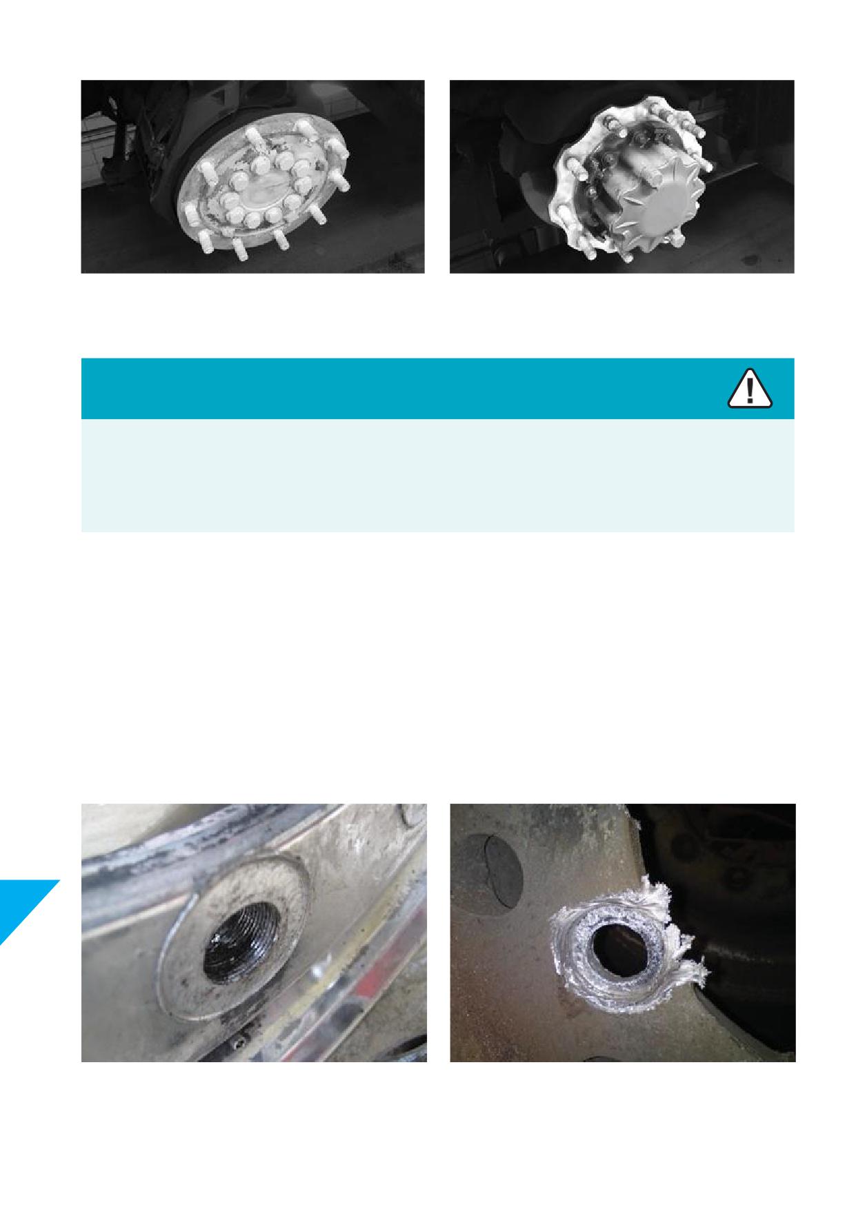
Picture 13-45
Picture 13-46
Circumferential hub
Star shape hub
Warning
• Due to the limited contact area of star shape hubs, proper maintenance and cleaning of hub, wheel and mounting hardware is
important.
• As per recommendation from the Association of European Wheel Manufacturers, EUWA, wheels used on star shape hubs (see
picture 13-46) must be checked for cracks on the inner and outer attachment face each 50.000 km.
• In case cracks are detected wheels are to be removed from service immediately and permanently.
13.h.ii. Bolt holes
If wheels run loose, both stud-located wheels and hub-piloted wheels can be damaged.
Look for wallowed out or elongated bolt holes as well as damaged studs and nuts:
• On hub-piloted wheels look for damage at the disc face and thread marks on the inside
diameter of the bolt holes.
• On stud-located wheels over torquing can also lead to damaged ball seats.
Remove wheels with damaged bolt holes from service immediately and permanently.
13
Picture 13-47
Picture 13-48
78
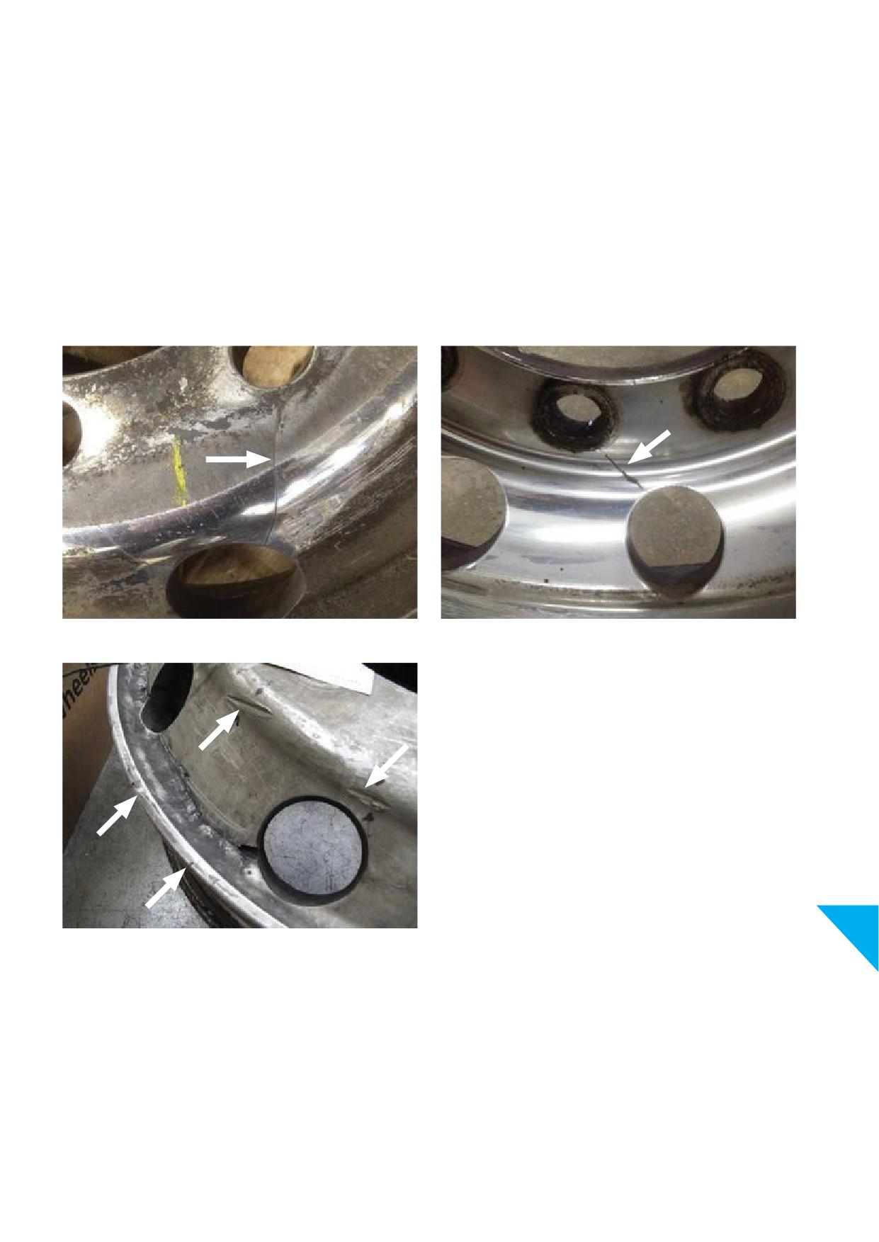
13.h.iii. Vent - or hand holes and disc area
Inspect both sides of disc area for vent - or hand hole cracks.
Exceeding wheel load capacity can cause damage to the vent
- or hand hole. A crack originates from the vent - or hand hole
The indication may be caused by, one or a combination of following
propagating in the disc area.
conditions:
Impacts on the rim fl
or vent - or hand hole area, e.g., a
• Overloading, uneven distribution of load on axles and / or
collision with curb stone or other obstacles may cause cracks
• Improper fi
lack of lubrication hardware and/or
propagating from vent - or hand hole to vent - or hand hole.
• Insuffi
maintenance (cleaning mating faces), and/or
• Application / use of non-spec / non-genuine hardware
Remove damaged wheels from service immediately and
permanently.
Picture 13-49
Picture 13-50
13
Picture 13-51
79
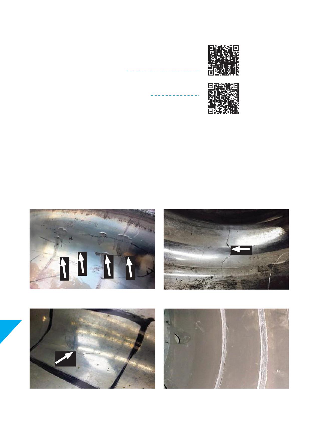
13.h.iv. Rim area (drop centre, valve hole area and bead seats)
Check the entire rim area for nicks, gouges, and cracks.
Cracks in the rim area are normally caused by overloading of the wheels.
If this type of wheel damage is observed, Howmet Wheel Systems
recommends using WorkHorse® Alcoa® Wheels.
See Alcoa® Wheels Specifi
Data Sheet for part numbers.
Loss of air may be caused by cracks in areas throughout the drop centre,
around the valve hole, and in the bead seat areas. Remove damaged
wheels from service immediately and permanently.
DROP CENTRE
Possible causes of drop centre cracks:
• Rim is too narrow for the tyre used
• Exceeding load or infl
capacity
• Corrosion damaged the rim
• Tyre tool damage, see picture 13-52
• Damage from foreign parts stuck between static brake calliper
and rotating wheel, see picture 13-55
Picture 13-52
Picture 13-53
13
Picture 13-54
Picture 13-55
81
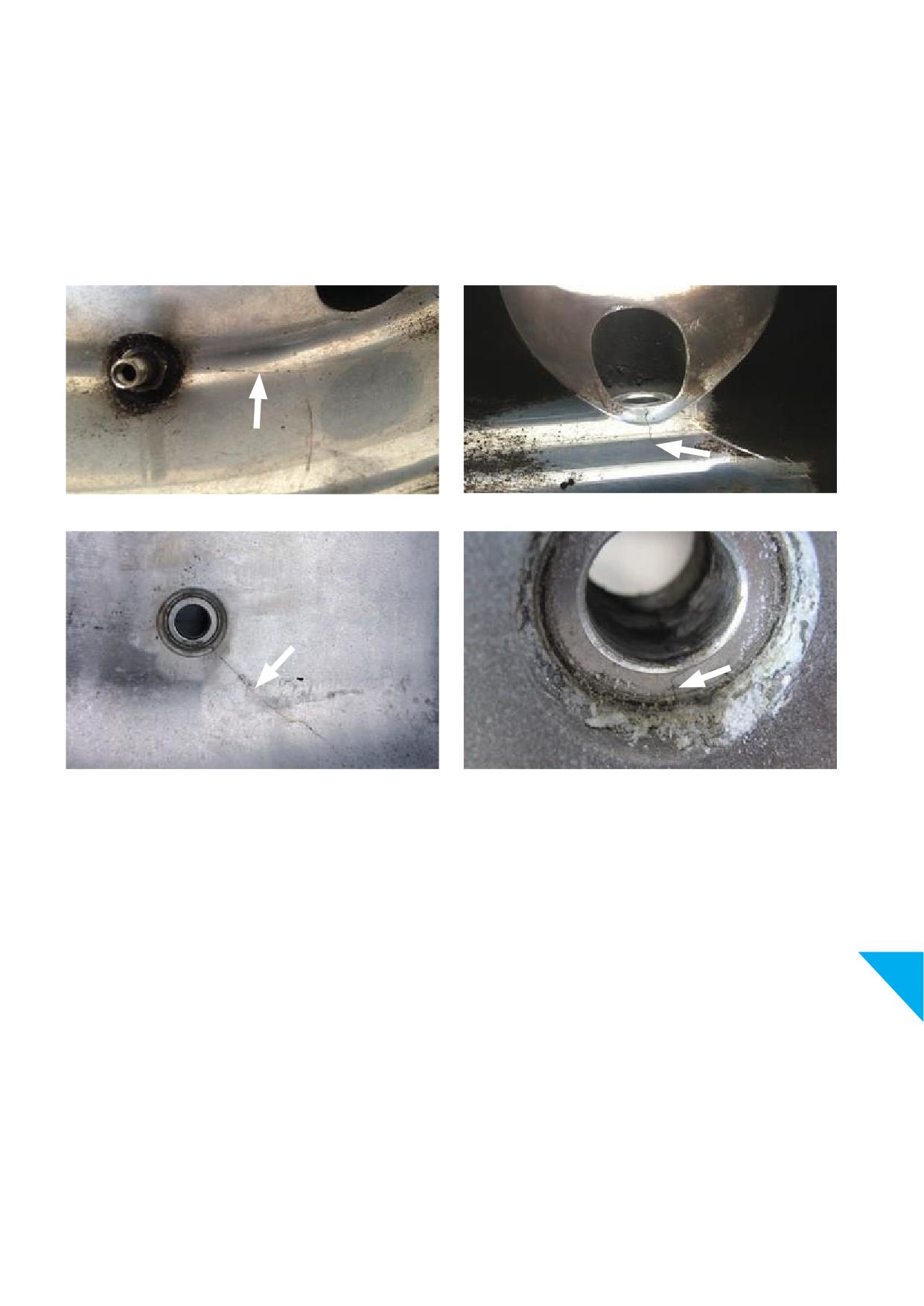
VALVE HOLE AREA
Possible causes for valve hole area cracks:
• Exceeding load or infl
capacity
• Corrosion, see section 13.i.iii.
• Rough fi
on the valve hole surface
• Use of non-spec or non-genuine valves, consult Specifi
Sheet for Alcoa® Wheels for correct valves
• Over-tightening the valve nut
Picture 13-56
Picture 13-57
Picture 13-58
Picture 13-59
13
80
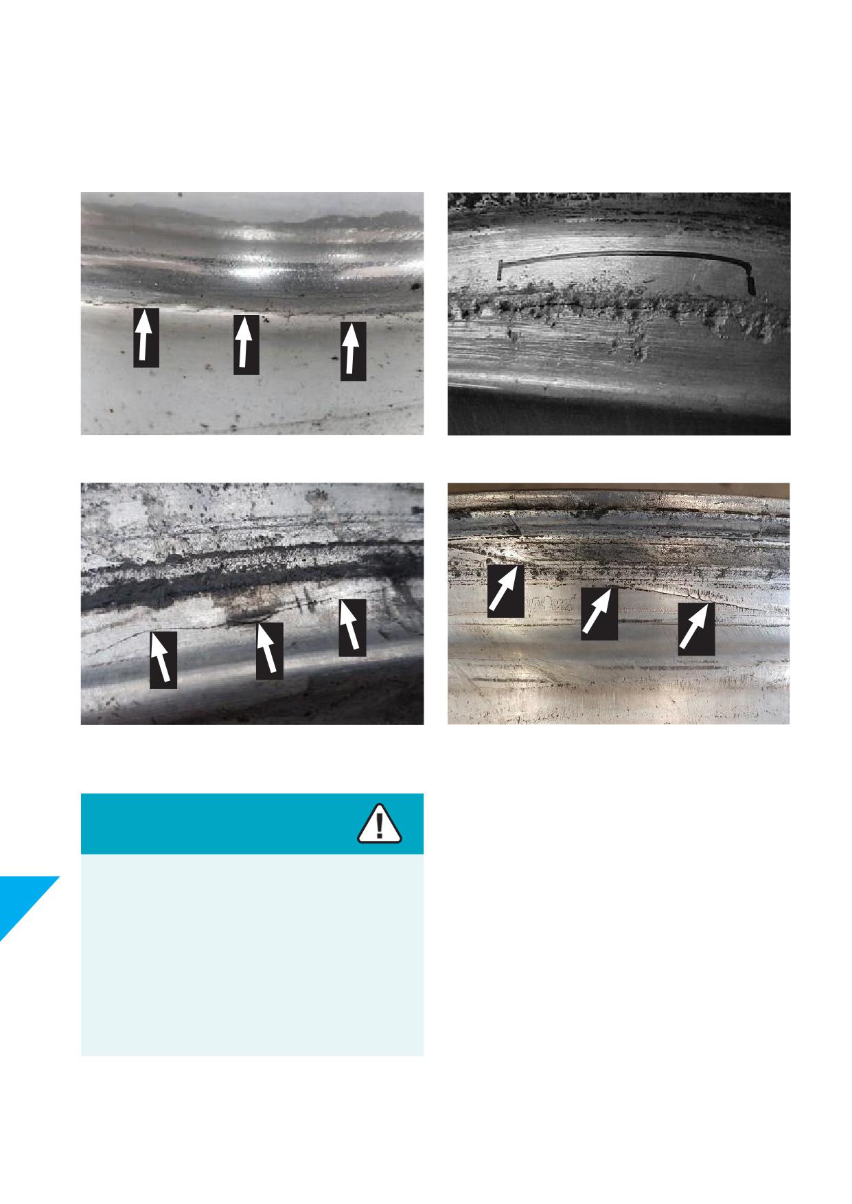
BEAD SEATS
Bead seat cracks may result from:
• Exceeding load or infl
capacity
• Corrosion (see picture 13-61)
• Tyre tool damage (see pictures 13-62, 13-63)
Picture 13-60
Picture 13-61
Picture 13-62
Picture 13-63
Warning
Use of inner tubes in tubeless wheels will hide slow leaks.
13
Slow leaks may indicate cracked or damaged wheels which
lead to wheel failures.
Wheel failures can cause accidents which may result in
serious injury or death.
Never use an inner tube on an Alcoa® Wheels tubeless wheel.
Immediately and permanently remove cracked or damaged
wheels from service and scrap.
82
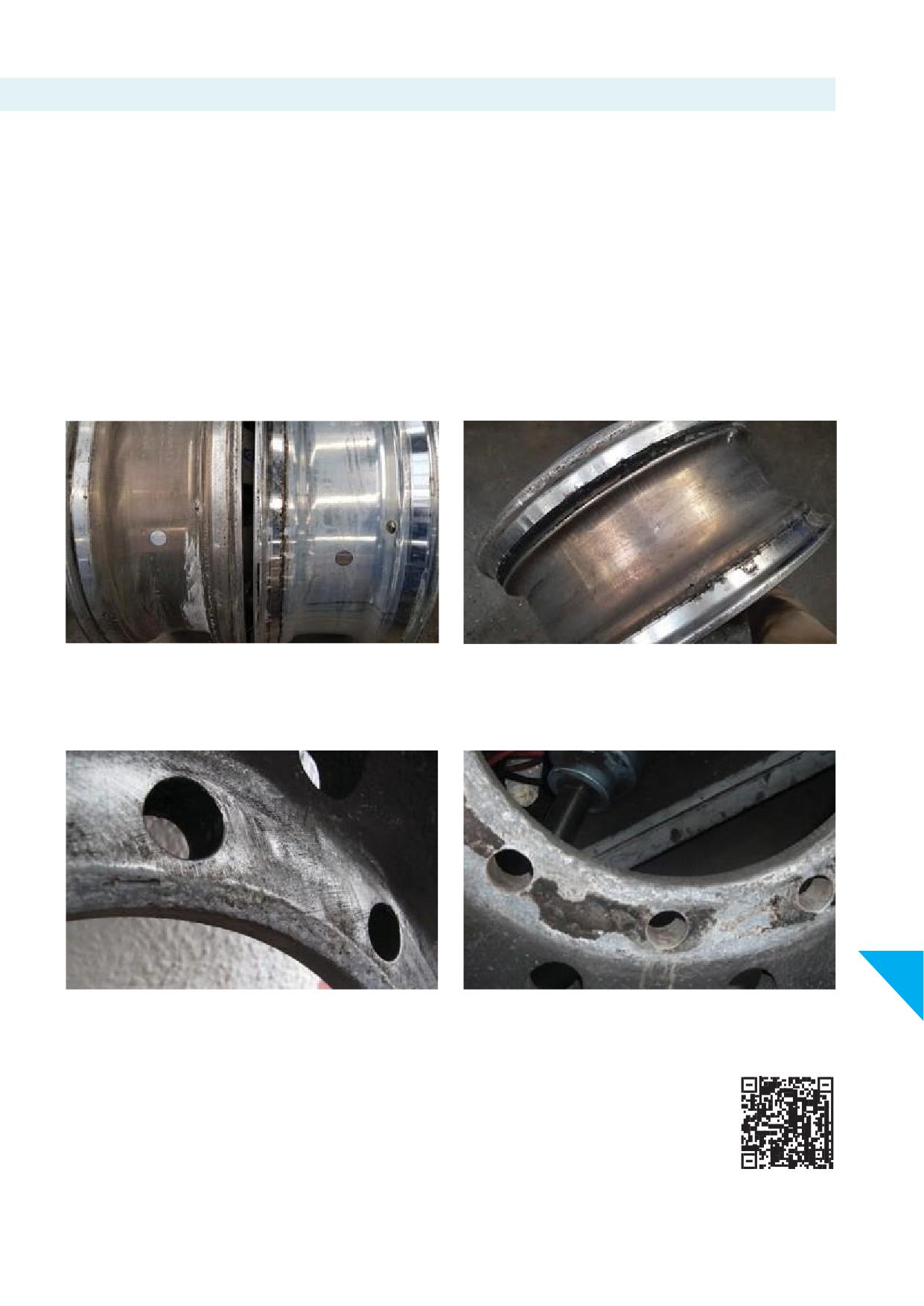
13.i. Corrosion
Certain environments canlead to corrosion, such aslivestock
Mild corrosion should be removed thoroughly by wire brush and
haulage or food related transport subject to frequent disinfectant
the tyre mounted with a non-water non-metal-based tyre lubricant.
cleaning. Some of the more common corrosives are salt,
magnesium chloride and calcium chloride compounds used for
Remove any severely corroded wheel from service.
snow removal and highly acid or alkaline materials.
Discolouring of the wheel part covered by the tyre is an indicator of
If the air used to infl
tubeless tyres, or the tyre, or the wheel
entrapped moisture. See pictures 13-64 and 13-65.
itself, is not dry, the areas of the wheel, drop centre, valve hole area
and bead seats, covered by the tyre can corrode severely.
Corrosion at the drop centre, valve hole area and bead seats
(Section 13.h.iv.) and hub bore is often caused by entrapped
moisture.
Picture 13-64
Picture 13-65
13.i.i. Corrosion at hub bore and wheel disc or mounting face
13
Picture 13-66
Picture 13-67
After removal of corrosion:
• The hub bore diameter may not exceed 0.5 mm or 0.02 inch
more than the dimension of the hub bore diameter as listed in
the Specifi
Sheet for Alcoa® Wheels.
Remove wheels from service with severe hub bore corrosion.
Specifi
Sheet for Alcoa® Wheels:
• The wheel disc i.e., when measuring the thickness, between the
mating areas with either hub or dualled wheel, may not be less
than 0.5 mm or 0.02 inch than the disc thickness as listed in the
Alcoa® Wheels Specifi
Sheet.
83
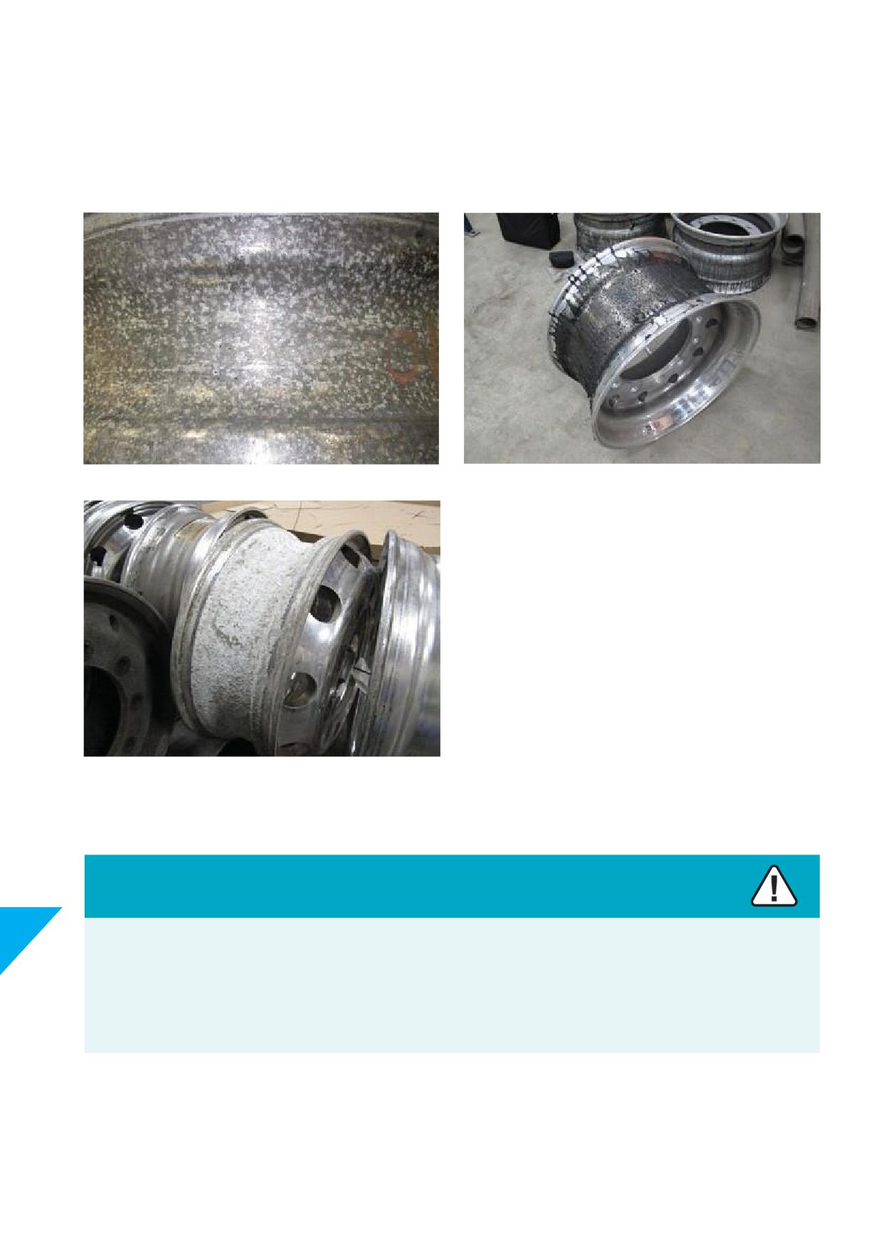
13.i.ii. Corrosion at drop centre
Corrosion at drop centre may result from:
• Entrapped moisture (see picture 13-68)
• Use of liquid tyre balancers or - sealants (see picture 13-69)
Picture 13-68
Picture 13-69
Picture 13-70
Caution
13
The use of liquid tyre balancers or - sealants in Alcoa® Wheels may cause extremely rapid corrosion of the wheel rim surface.
Severely corroded wheels are unsuitable for service.
Alcoa® Wheels corroded using liquid tyre balancers or - sealants will not be replaced under the Howmet Wheel Systemslimited
warranty.
84
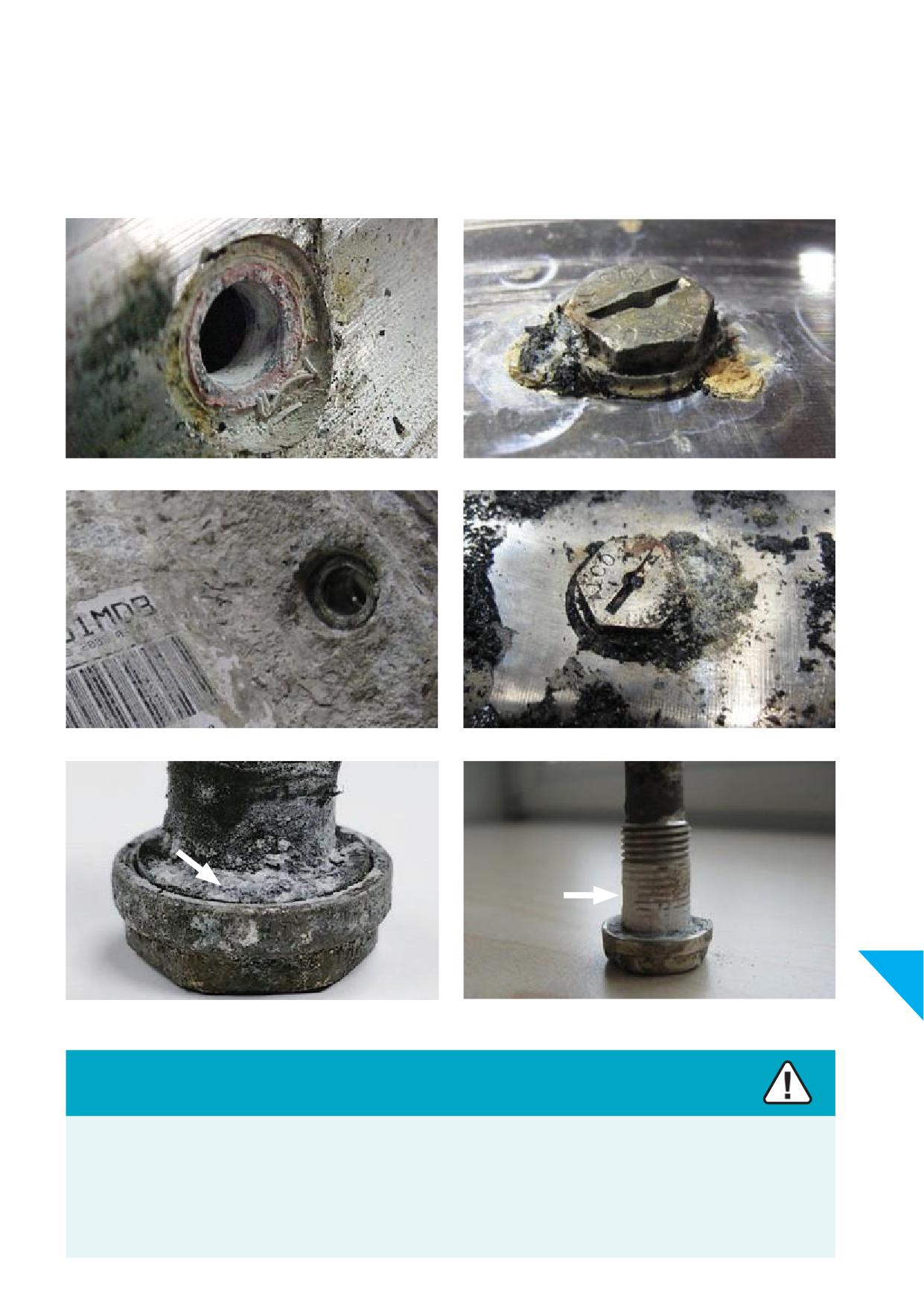
13.i.iii. Corrosion at valve hole area
Corrosion at valve hole area may result from:
• Entrapped moisture
• Use of tyre mounting paste to lubricate valve
• Use of liquid tyre balancers or - sealants
Picture 13-71
Picture 13-72
Picture 13-73
Picture 13-74
13
Picture 13-75
Picture 13-76
Caution
The use of liquid tyre balancers or - sealants in Alcoa® Wheels may cause extremely rapid corrosion of the valve hole area.
Wheels with severely corroded valve hole areas are unsuitable for service.
Alcoa® Wheels corroded using liquid tyre balancers or - sealants will not be replaced under the Howmet Wheel Systemslimited
warranty.
85
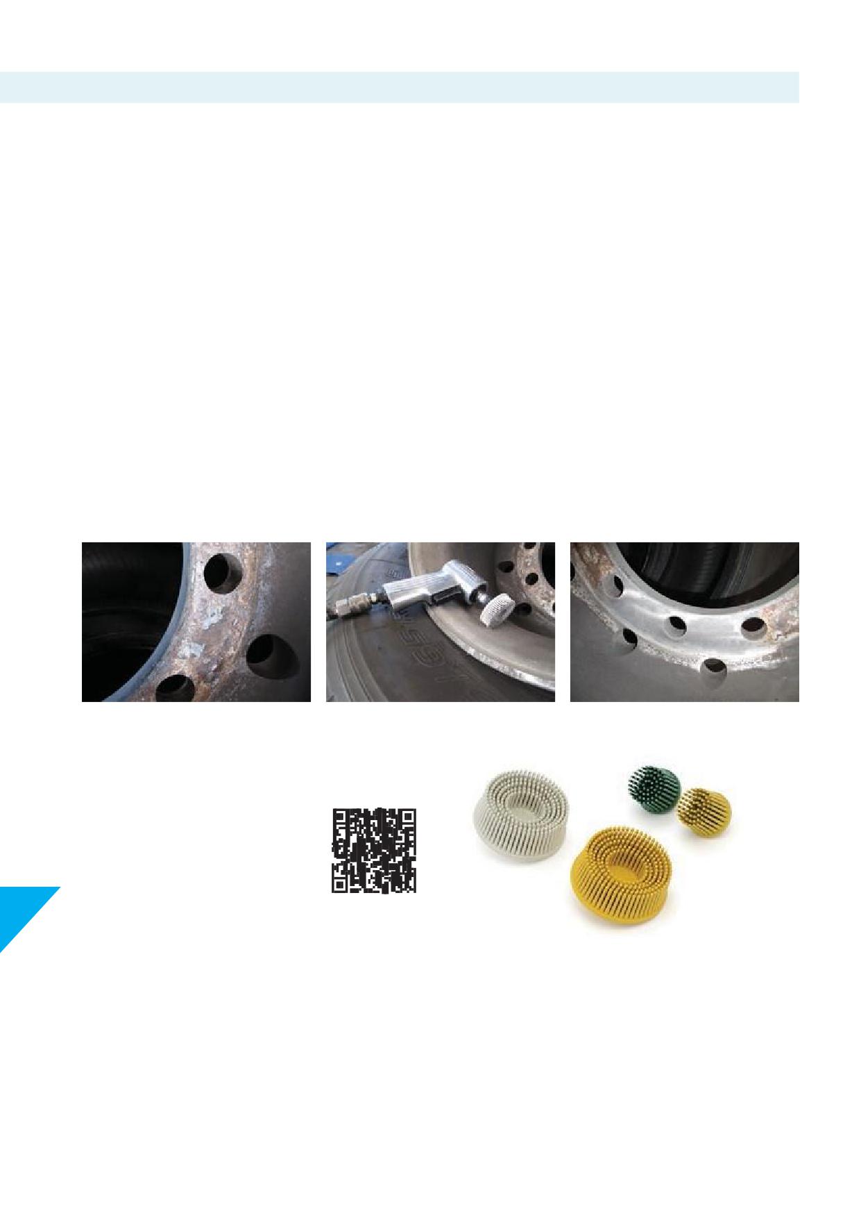
13.j. Regular inspection and removal of corrosion
In addition to the recommendations provided in Section 14 Care
NOTE
and Maintenance of this manual, maintenance of aluminium
The inside facing surface of non-reversible Dura-Bright® wheels
wheels is required to ensure a safe and reliable service life.
have no surface treatment.
Frequent cleaning of aluminium wheels and removing corrosion
IMPORTANT
will not only contribute to the looks of the vehicle but -more
Oxidation will occur with corrosion build up as a result.
important- will add to a safe and reliable operation of the vehicle
If wheels are not cleaned regularly, excessive corrosion build
during the wheels’ servicelife.
up may contribute to cause wheels to fail either by initiating or
accelerating hair line cracks.
Brushed, Mirror Polished and LvL ONE® Alcoa® Wheels are
uncoated. The bare aluminium or non-surface treated and highly
Any excessive corrosion build-up must be removed at vehicle
corrosion resistant alloy that is used for Alcoa® Wheels reduces
inspection intervals, before placing wheels in service again or upon
oxidation to a minimum. Corrosion build up may occur on all
tyre change or repair.
surfaces if wheels are not cleaned regularly.
CLEANING MATING FACES (wheel disc and hub or drum):
Dura-Bright® Alcoa® Wheels have a surface treatment that protects
the wheels’ surface against oxidation. The treatment may get
After cleaning the mating faces, the disc (bolt hole) area of the
damaged or erode during service life.
wheel and the mounting area of the hub, must be dry, clean,
smooth, and fl before mounting.
Consult section 10.a. Wheel installation preparation
Picture 13-77
Picture 13-78
Picture 13-79
The abrasive tools used in these pictures are available from
authorized distributors of Alcoa® Wheels, reference: Bristle Discs for
Alcoa® Wheels.
For documentation contact Howmet Wheel
Systems or go to the web page
13
Picture 13-80
CLEANINGNON-MATINGFACES:
For more information about care and maintenance of untreated
surfaces (Brushed, Mirror Polished and LvL ONE®) and
Dura-Bright® surface treated Alcoa® Wheels refer to the following
pages, Section 14, of this manual.
86
14. Care and Maintenance
Regular cleaning
Clean the wheels regularly with steam or high-pressure water.
Do not use harsh acidic or harsh alkaline cleaners. Do not use
hydrofl
acid. Do not use abrasive products or tools to clean or
polish Alcoa® Wheels.
14.a. Maintenance against corrosion for Brushed, Mirror Polished and LvL ONE®
wheels (non-Dura-Bright® surface treated wheels)
These wheels can be identifi by the blue Alcoa® logo on the sticker:
The following information is for Alcoa® Wheels without the
Dura-Bright® surface treatment.
See Section 14.b. for specifi instructions on the care and cleaning
of Dura-Bright® surface treated Alcoa® Wheels.
For Alcoa® Wheels with Brushed, Mirror Polished or LvL ONE®
fi
1. Clean frequently with steam or high-pressure water. The use of
a mild detergent will speed the cleaning process. Use no harsh
acidic or harsh alkaline cleaners. Do not use hydrofl
acid.
Picture 14-1
Picture 14-2
2. When tyres are removed the entire wheel must be cleaned and
inspected. See Sections 5, 6 and 13.
With Bristle Discs for Alcoa® Wheels or a wire brush, remove
dirt and contamination from the tyre side of the rim. Do not
use Bristle Discs for Alcoa® Wheels or a wire brush to remove
dirt and corrosion from the appearance surface
of the wheel. Bristle Discs for Alcoa®Wheels are
available from authorized distributors of Alcoa®
Wheels.
Picture 14-3
Picture 14-4
3. To maintain the original appearance of your Alcoa® Wheels, the
UseALcleanandALpolishfromHowmetWheelSystems
following procedures are recommended:
a) After installing new wheels and prior to operating your
Alcoa® Wheels with Brushed, Mirror Polished and LvL ONE® fi
vehicle, use the ALbrush for Alcoa® Wheels or a soft fi
are uncoated. The highly corrosion resistant alloy that is used for
brush to wash the visible wheel surfaces with a mild
Alcoa® Wheels reduces oxidation to a minimum. Maintaining the
detergent and warm water solution.
original lustre of the wheels is easy with ALclean and ALpolish.
b) Flush thoroughly with clean water.
Regular and frequent maintenance will keep your wheels bright
c) Wipe dry to avoid water stains.
and shiny for years.
14
d) Clean your Alcoa® Wheels every week to maintain their
appearance.
For reference see the 'How to Clean' page on our
website:
87
14.b. Maintenance and cleaning Dura-Bright® XBR® and Dura-Bright® EVO surface
treated wheels
These wheels can be identifi by the Alcoa® logo on the sticker,
Dura-Bright® surface treated wheels’ part number have extension
which is black for Dura-Bright® XBR® or black and green for
DB or DD. See Section 4.d.
Dura-Bright® EVO.
Ultra ONE® DURA-BRIGHT® EV
Picture 14-5
Picture 14-6
Picture 14-7
Dura-Bright® wheels are easy to clean and stay bright and shiny
material. If soils and dirt remain, use Dura-Bright® Wheel Wash
when properly maintained.
or warm water and a mild detergent using high pressure power
washer.
Dura-Bright® wheels are maintained best with Dura-Bright® Wheel
Wash, a standard car wash soap or a near pH neutral detergent.
Always dilute the detergent according to the manufacturers’
recommendations; never use the detergents straight without
If soils and dirt attached to the surface do not come off with cold
diluting with water.
water, try warm water and wipe with a soft towel or chamois
Dura-Bright® Wheel Wash for Alcoa® Wheels is available from
authorized distributors of Alcoa® Wheels.
For reference see the 'How to Clean' page of our website:
IMPORTANT
14
Dura-Bright® Alcoa® Wheels should NOT be polished with polishing compounds or ALpolish.
Picture 14-8
88
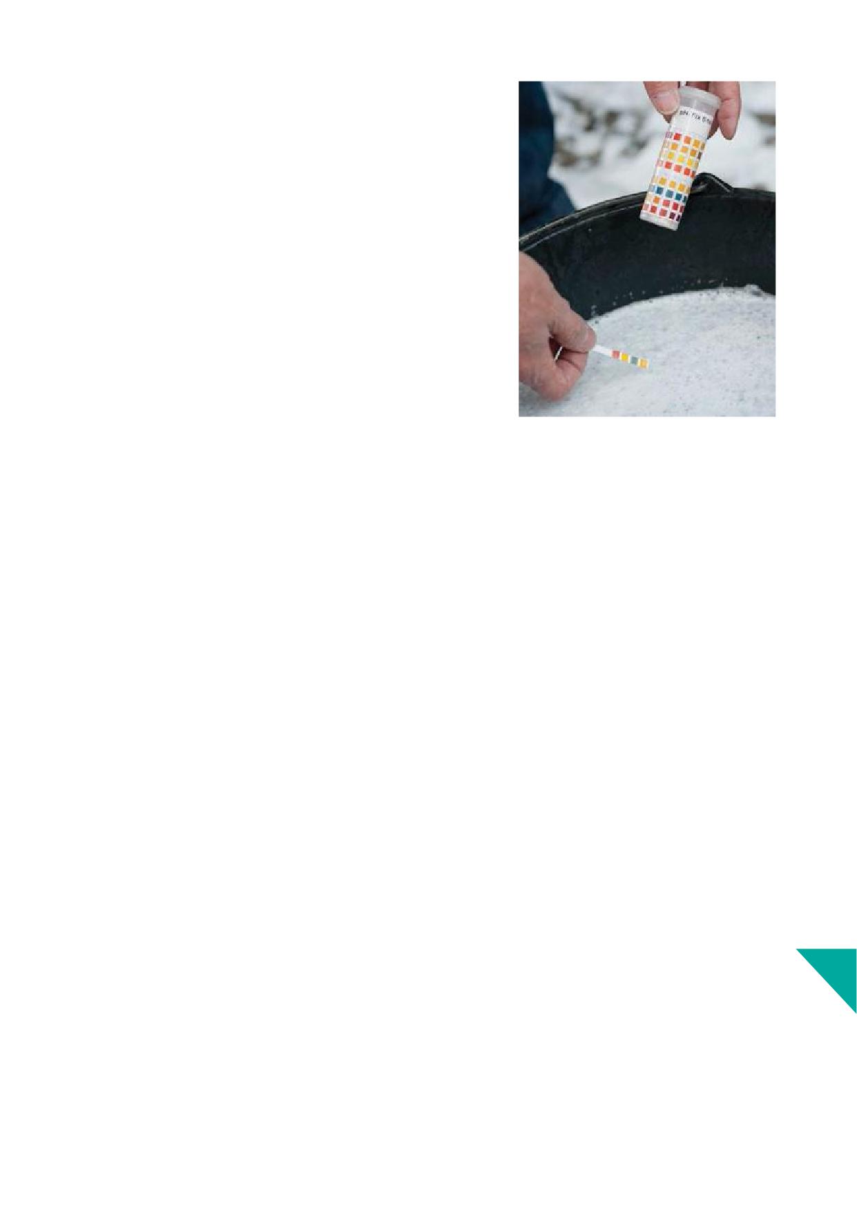
IMPORTANT
Do not use strong acidic or strong alkaline products on Dura-Bright® surface treated
wheels.
Hydrofl
acid (HF) should never be used on Dura-Bright® surface treated
wheels.
The pH value of the cleaner can be found in the MSDS (Material Safety Data Sheet).
If the cleaner is undiluted, consult your cleaning products supplier to determine pH
levels and dilution.
Pictured an example of how to test pH value with pH indicator strips (See picture
14-9).
NOTE
Dura-Bright® Wheel Wash for Alcoa® Wheels can be used without diluting.
Picture 14-9
IMPORTANT
The Dura-Bright® surface treatment for Alcoa® Wheels is developed to enable eff
cleaning wheels, with mild and environmentally
friendly cleaning products, maintaining the looks and shine the easy way.
Professional cleaning products for commercial vehicles, stationary and mobile vehicle wash service providers may contain and use strong
acidic and alkaline components that may harm the Dura-Bright® surface treatment for Alcoa® Wheels.
Before cleaning Dura-Bright® surface treated wheels it is recommended to check and evaluate following with the supplier or service
provider:
1. Type of chemical components in product(s) used as per material safety data sheet (MSDS).
2. Dilution of the product(s) with clean water, or pH value.
3. Temperature, of both wheel surface and mating components.
4. Time of exposure recommended for the product(s) to be used safely and eff
to clean the surface.
NOTE
Cleaners that are safe to use on windows and painted panels and bodywork can be used on Dura-Bright® surface treated Alcoa® Wheels
Consult the recommendations in this Section. In case of doubt contact Howmet Wheel Systems.
14
89
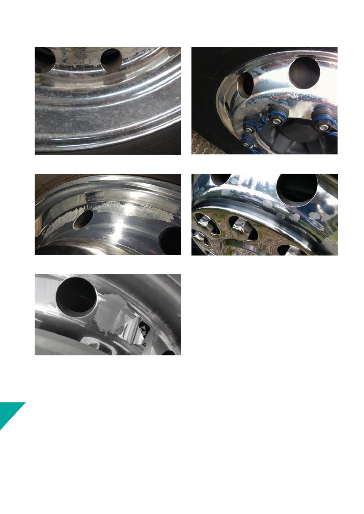
Examples of Dura-Bright® surface treated wheels exposed to aggressive cleaners. See pictures 14-10 to 14-14.
Picture 14-10
Picture 14-11
Picture 14-12
Picture 14-13
Picture 14-14
See Section 14.b.i. how to clean Dura-Bright® XBR® and Dura-Bright® EVO surface treated Alcoa® Wheels in 5 steps.
14
91
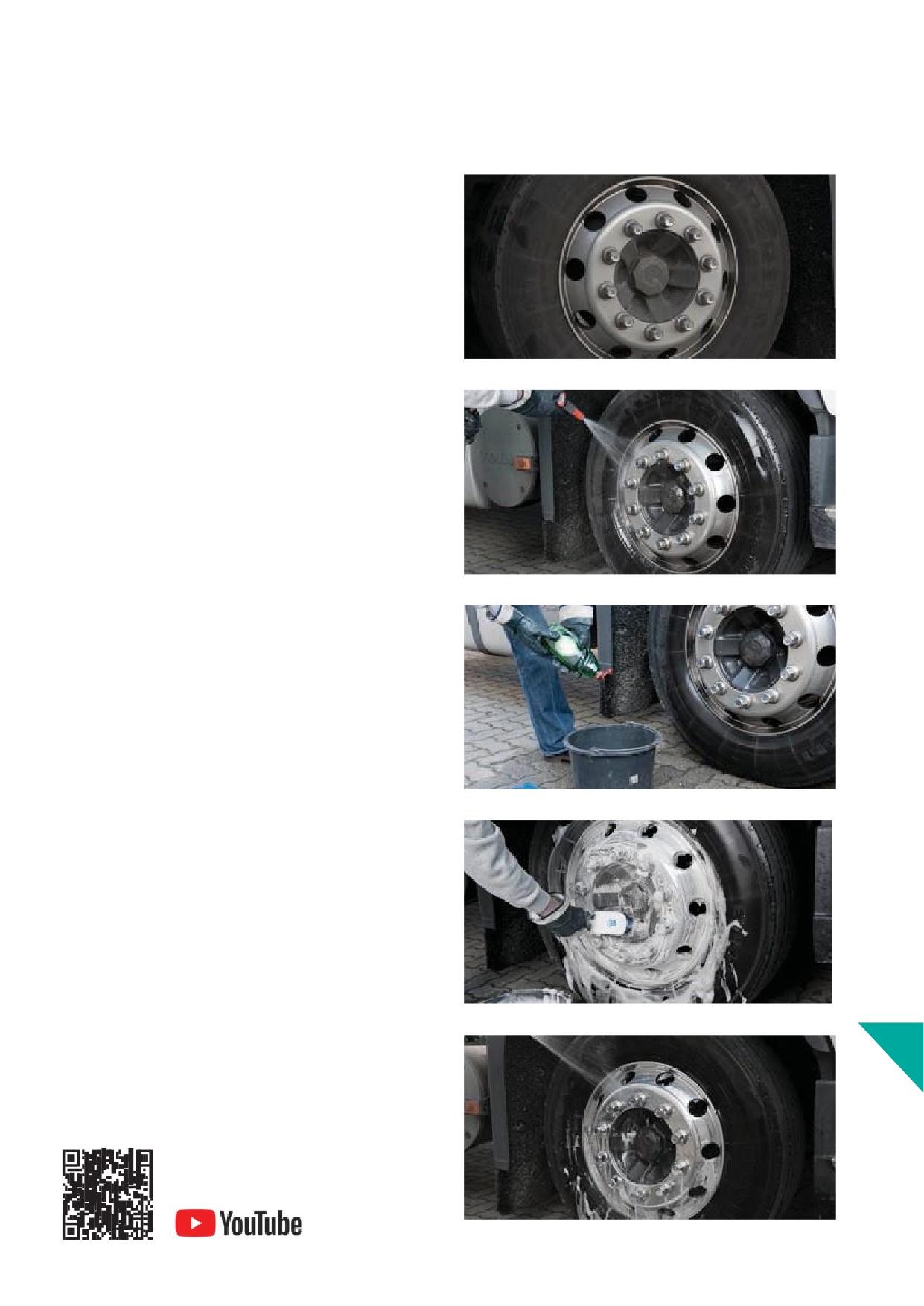
14.b.i. Maintenance and cleaning Dura-Bright® XBR® and Dura-Bright® EVO surface
treated Alcoa® Wheels in 5 steps
STEP1
Before cleaning, allow wheels to cool down to a temperature below
35°C or 95°F.
Picture 14-15
STEP2
Flush the wheels thoroughly to remove any loose and visible dirt
and debris. Flushing the wheels with water helps to help preventing
scratching and abrasion. Use a water hose or power washer to
remove soil, sand, etc.
Picture 14-16
STEP3
Use undiluted Dura-Bright® Wheel Wash for Dura-Bright® Alcoa®
Wheels, a standard car wash or a (near pH neutral) detergent. Add
car wash or a mild detergent (e.g., common dish soap liquid) to the
water at the specifi dilution ratio before applying to the wheels.
• Do not use harsh acidic or harsh alkaline cleaners.
• Do not use hydrofl
acid (HF).
Picture 14-17
STEP4
Clean the wheels. Apply Dura-Bright® Wheel Wash for Dura-Bright®
Alcoa® Wheels, soap, or detergent generously on wheel surface
with the ALbrush for Alcoa® Wheels or a soft fi
brush. Do not use
abrasive tools and scouring pads (e.g., 3M Scotch-Brite®).
Picture 14-18
STEP5
14
Flush the wheels thoroughly with clean water and remove all
remaining soap and dirt. Dry the wheels using a soft cloth free of
debris.
Picture 14-19
90
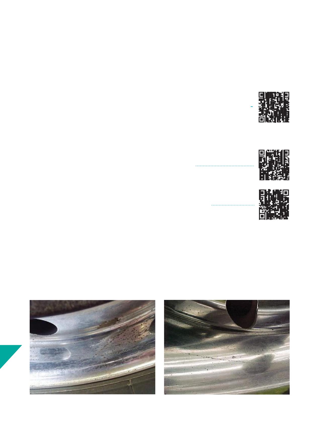
14.b.ii. Additional care and tips for Dura-Bright® XBR® and Dura-
Bright® EVO surface treated Alcoa® Wheels
Once in service, Dura-Bright® surface treated Alcoa® Wheels can
NOTICE
become nicked or scratched by road debris and/or mechanical
For maintenance of Dura-Bright® surface treated Alcoa® Wheels
damage. If this occurs, continue to follow the normal washing and
that were and are subject to damage, handling marks, erosion and
cleaning instructions provided in Section 14.b.i.
discolouring of the Dura-Bright® surface treatment, refer to 2. and
3. of this section, or contact:
The mounting area on Dura-Bright® surface treated Alcoa® Wheels
can become scratched, marred, or discoloured when mounted
against another wheel, hub, or drum. Wheel mounting surface
Howmet Wheel Systems Fleet Service Center:
guards, such as Discmates for Alcoa® Wheels or other nylon
protection gaskets, can be used.
1. Regular conditions do not require special routines
Dura-Bright® wheels can be kept clean with Dura-Bright® Wheel
Wash for Alcoa® Wheels, soap an water, or with mild acid washes
How to clean:
that also can be used safely on the vehicles’ painted surfaces.
Products for cleaning:
2. Conditions that may require an additional maintenance practice
Handlingmarks, traces of use
Dura-Bright® surface treated Alcoa® Wheels with handling marks or
traces of use (e.g., scratches, nicks, dents, or gouges) build up disc
brake dust on those parts of the surfaces where the Dura-Bright®
surface treatment is missing. These surfaces will look as if they have
not been treated with Dura-Bright®.
14
Picture 14-20
Picture 14-21
92
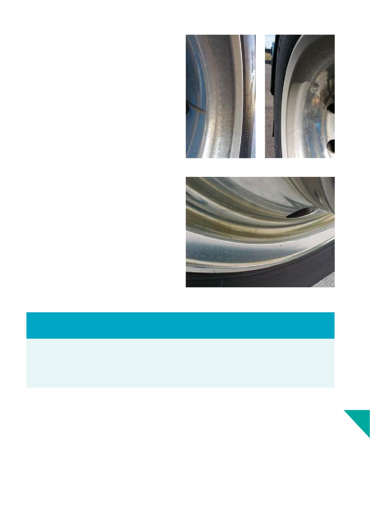
Erosion
Dura-Bright® surface treated Alcoa® Wheels mounted on vehicles
used on gravel roads or on asphalt roads where sand, stones
or other material erode the Dura-Bright® surface treatment, will
gradually show a declining layer of treatment.
Due to the missing full coverage of Dura-Bright® surface treatment,
the surfaces will show oxidation or a gradual build-up of disc brake
dust at the rim fl
area.
Picture 14-22
Picture 14-23
Discolouring
Dura-Bright® surface treated Alcoa® Wheels on axles with disc
brakes may show a gradual discolouring over time. Mostly seen on
front axles, wheels will develop a brownish, copper, or golden haze
next or off to the vent holes depending on the rotation
direction. This discoloration is a tarnish, and the result of the
substances released from the disc brake pads when braking.
The above-mentioned conditions may appear sooner after a winter
period or at longer intervals between cleanings. More frequent
cleaning with Dura-Bright® Wheel Wash for Alcoa® Wheels, soap,
and water or a mild acid cleaner is recommended.
Picture 14-24
Notice
These conditions i.e., handling marks, traces of use, erosion and/or discolouring, are not warrantable.
Filiform corrosion (worm or hair like lines, underneath surface protective treatment and emanating from damage to the surface
treatment) and blistering or peeling due to loss of adhesion of the surface treatment is warrantable for a period of 60 months from
date of manufacturing.
See ‘Limited Warranty’ Section 2 for reference.
3. Additional maintenance practice
• Wheels or parts of wheels that show conditions as described
14
above may require additional maintenance.
• The use of ALclean with the ALbrush is recommended to remove
disc brake dust, corrosion, or discolouring, as with regular
untreated surfaces.
• The Dura-Bright® surface treatment will not be aff
using
ALclean if it is used on limited occasions and time.
93
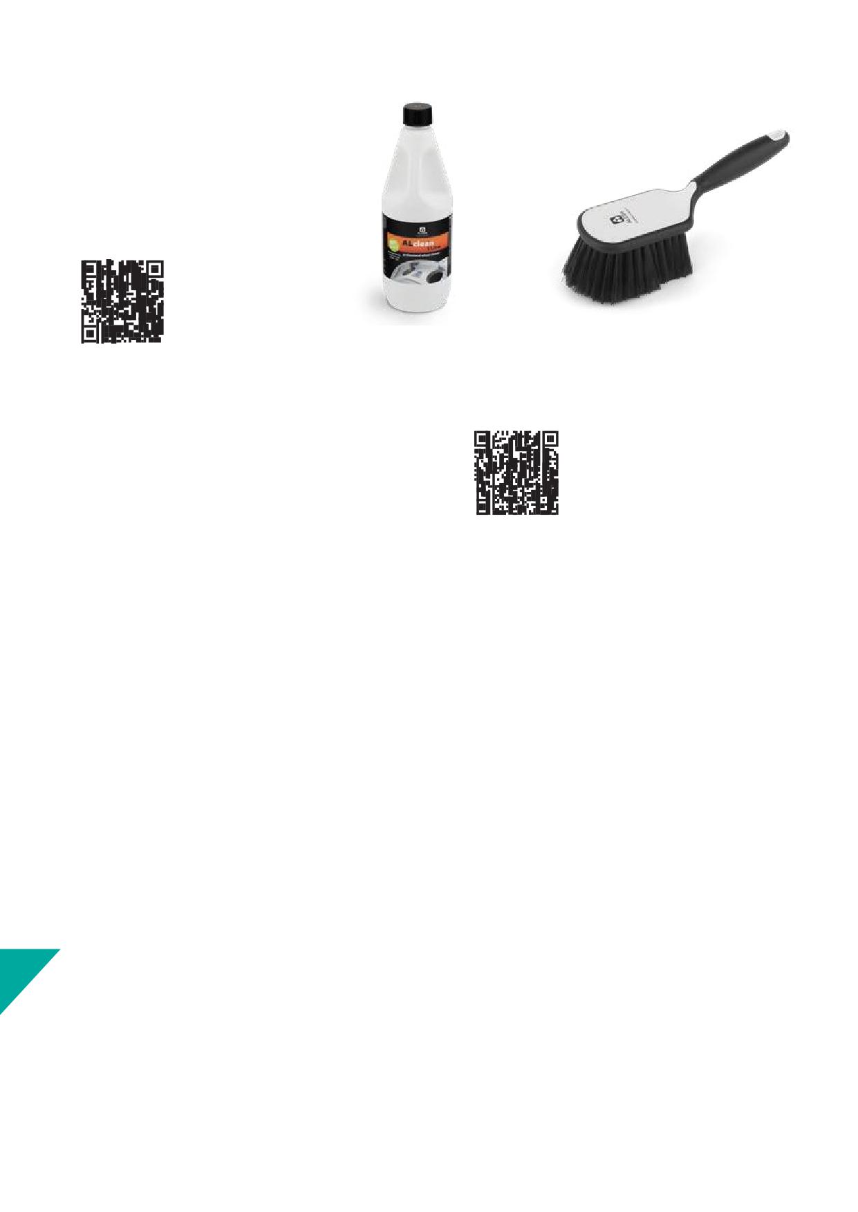
ATTENTION
Read the safety instructions on the label of
the ALclean 1 litre bottle or 5 or 25 litres can.
Material Safety Data Sheets are available via
'Safety Data (MSDS)' link at the bottom of the
Cleaning webpage:
Picture 14-25
Picture 14-26
ALclean 1 litre bottle
ALbrush2 soft fi
brush
ALclean and ALbrush2 are available from authorized distributors of
Alcoa® Wheels.
How to proceed:
1. Allow the wheels to cool down before cleaning. The
recommended temperature of the wheels should be below
35°C or 95°F.
2. Remove all nut covers if present.
3. Thoroughly remove dust, sand, with water from a hose or a
high-pressure washer. Do not dry the wheel.
4. Use a limited quantity, 100 ml or 3.45 fl oz of undiluted ALclean
with the ALbrush, or brush with soft fi
and gently brush
the wheel 2 to 3 times with short breaks for 2 to 3 minutes in
total.
5. Flush the wheel thoroughly with cold or lukewarm water.
6. Repeat step 4 and 5 until disc brake dust, corrosion and/or
discolouring are removed.
7. After the wheel has dried, refi the nut covers.
For regular cleaning of Dura-Bright® wheels, continue to use
Dura-Bright® Wheel Wash for Alcoa® Wheels or soap and water
frequently as described in Section 14.b.i.
Perform the additional maintenance using the ALclean as described
in steps 1 to 7 on limited occasions only.
14
94
14.c. Maintenance Dura-Flange® wheels
These wheels can be identifi by “DF” or “DD” after the 6-digit P/N.
See Section 4.d.
Dura-Flange® wheels have blue logo Alcoa® Wheels stickers (DF) or
black logo Alcoa® Wheels stickers (DD) and two additional stickers
with Dura-Flange® Rim Wear Protected printed.
1. Dura-Flange® rim fl
treated wheels have a 24-month
warranty against wear which creates a sharp edge that would
require maintenance.
2. Minor wear or minor pitting is not a warrantable condition. See
Section 13.g.iv.
3. Rim fl
reconditioning cannot be performed on wheels with
Picture 14-27
a Dura-Flange® treatmentincluding those methods described
in Section 13.g.iii.
The surface of wheels treated with Dura-Flange® can be cleaned
as described in Section 14.a. for non-surface treated wheels (DF),
or as described in Section 14.b. for Dura-Bright® surface treated
wheels (DD).
14
95

15. Out-of-Service Wheels
Identifi
of Out-of-ServiceWheels and Proper Disposal
and Recycling
Alcoa® Wheels are made of aluminium. Aluminium is almost 100%
recyclable.
Out-of-Service Wheels
Wheels should be removed from service when inspection reveals
out of service conditions that render a wheel no longer serviceable.
Conditions such as cracking, corrosion, wallowed bolt holes and
worn rim fl
are examples of conditions that may cause a
wheel to be removed from service. See Section 13 (Wheels in
service) of this manual or Technology and Maintenance Council
(TMC) Users Guide to Wheels and Rims RP222 for examples of
wheels that should be removed from service.
Proper Disposal and Recycling
Picture 15-1
Comply with local, state, and national environmental regulations
with respect to out-of-service wheels. Howmet strongly encourages
you to recycle wheels that are no longer serviceable. Before off
Alcoa® Wheels to an appropriate recycling company:
• Make the wheel permanently unserviceable beyond repair by
drilling out the date stamp in the wheel or using a torch to cut a
slot into the rim fl
on the open side of the wheel
• Remove, deface, or make illegible the serial number, date code,
and part number
• Remove valves, tire pressure monitor sensors (TPMS), balancing
weights, and other components. Follow local, state, and national
environmental regulations for disposing of these components
According to the European Commission all Alcoa® Wheels (part
numbers and fi
are classifi as non-hazardous waste and
can be disposed of and recycled.
Thank you for contributing to worldwide sustainability eff
by
returning Alcoa® Wheels to the recycling chain, which reduces
landfi waste and leads to further opportunities for using the
aluminium.
15
96
16. Glossary of common terms and
conversion factors
16.a. Glossary of common terms
15° the angle of the tyre's beads and wheel's bead seats as used for
ET - stands for Einpresstiefe. Commonly found on steel wheels.
tubeless tyres and wheels for medium- and heavy-duty vehicles.
German for Off (or Inset). See INSET.
1 PIECE FLANGE NUT - A 1-piece washer and nut combination. Not
fl oz - fl
ounces, liquid volume measurement
recommended for use on any Alcoa® Wheels application.
FMVSS - Federal Motor Vehicle Safety Standards (U.S.A.)
2 PIECE FLANGE NUT - A 2-piece washer and nut combination used
to secure hub piloted wheels.
FOOT-POUNDS / NEWTON METRES - The measure of the amount
of torque applied to a nut or other part. May be measured with a
AIR CHAMBER - The space enclosed by a tyre and rim of the wheel.
torque wrench.
BEAD SEAT - The tyre seating surface (2x) of the rim (See graphic
ft-lbs. - abbreviation for Foot-pounds, torque measurement.
16-1).
HDS or 1/2 DUAL SPACING - Measurement for use of wheels in dual
BOLT CIRCLE - The circle defi
by connecting the centres of the
application. Half the distance between the two centrelines
bolt holes (mounting holes) of a wheel, dimension of diameter
of a dualled tyre/wheel assembly. The dimension is the same as the
stated in millimetres or inches (See graphic 16-1).
OUTSET dimension (See graphic 16-1).
BOLT HOLES or mounting holes - Holes in the disc of the wheel
HMA - abbreviation of ‘Halber Mittenabstand’. German for Half Dual
through which the bolts (studs) pass.
Spacing see “HDS” (See graphic 16-1).
CENTREBORE - See“HUB BORE” (See graphic16-1).
HUB BORE - The centre hole of a disc wheel, dimension of diameter
stated in millimetres or inches (See graphic 16-1).
CLOSED SIDE - The disc face, top side or beauty face of a wheel that
can be mounted in a dual application. See also OPEN SIDE.
HUB PILOTED MOUNTING - A wheel mounting system which uses
the hub to centre the wheel (in single application) or both wheels (in
DC - Abbreviation for drop centre. See “DROP CENTRE” (See graphic
dual application) and 2-piece fl
nuts to secure wheel(s).
16-1).
in. - Abbreviation for inches (distance measurement). 1 inch equals
DISC AREA - The vertical part of the wheel which supports the rim
25.4 mm.
and is connected / faced to the hub, or the other wheel’s disc in
case of a dual mounting (See graphic 16-1).
INNER CAP NUT - Nut used to mount the inner wheel in a dualled
stud located wheel system. Not applicable for hub piloted wheels.
DISCMATE - A nylon protection gasket that goes between the hub
or brake drum and wheel and/or between two wheels to help
INSET or OFFSET - The distance from the wheel mounting surface
reducing corrosion.
to the rim centreline when the centreline is placed inboard of the
mounting surface. Measurement used for single wheel application.
DISC WHEEL - A 1-piece (forged) or 2-piece (welded) assembly of a
Dimension stated in millimetres or inches (See graphic 16-1).
disc and a rim.
kg - Abbreviation for kilogram, equal to 1000 grams, weight
DOT - abbreviation for Department of Transportation, federal
measurement.
cabinet department of the U.S. government concerned with
transportation.
kPa - Abbreviation for Kilopascal, 100 kPa equals 1 bar, pressure
measurement.
DROP CENTRE - The well or centre portion of the wheel rim that
enables the fi
of a tubeless tyre (See graphic 16-1).
lb. - symbol for pound, weight measurement.
DUAL WHEEL - Any wheel that can be mated disc side to disc side
LONG SLEEVE NUT - A (retrofi nut with a long extension sleeve
16
with a similar wheel resulting in an inner and outer dual wheel
used to secure dualled wheels (see also SHORT SLEEVE NUT).
assembly. See also SINGLEWHEEL.
97
MAXIMUM INFLATION - The highest amount of air pressure
RIM - That portion of the wheel which supports the tyre.
allowed, measured at ambient (cold) temperatures, approx. 20°C
SAFETY HUMP - Small and integral raised part of the wheel situated
(Celsius) or 68°F (Fahrenheit).
on lower end of one bead seat near the drop well. Prevents the tyre
bead from slipping into the drop well when tyres are operated at
millilitre - ml, 1000 millilitres equals 1 litre, liquid volume
low or defl
tyre pressure (See graphic 16-1).
measurement.
SHORT SLEEVE NUT - A retrofi nut with a short extension sleeve
mm - Abbreviation for millimetres. 1000 mm equals 1 meter.
used to secure a single wheel. See also LONG SLEEVE NUT.
MOUNTING FACE - Disc area, mounting area, support surface
SINGLE WHEEL - A single mounted wheel, or any wheel that cannot
diameter, that portion of the wheel face which contacts the hub or
be mated disc side to disc side with another wheel. See also DUAL
brake drum, or the adjacent wheel in case of a dual mounting (See
WHEEL
graphic 16-1).
STUDS - Threaded bolts extending from the hub surface to which
NEWTON METERS / FOOT-POUNDS - The measure of the amount
the wheels are secured by the nuts (See graphic 16-1).
of torque applied to a nut or other part. May be measured with a
torque wrench.
STUD LOCATED, BALL SEAT MOUNTING - A wheel mounting system
which uses the studs and spherical ball seat nuts to centre and
Nm - Abbreviation for Newton meters, torque measurement.
secure the wheel. Not applicable for hub centred wheels.
OFFSET - also referred to as INSET, see both INSET and OUTSET
TORQUE - The amount of force used to tighten nuts. Usually stated
(See graphic 16-1).
in Newton-meters or Foot-pounds and measured with a torque
wrench. Torque measurement.
OPEN SIDE - The side of the wheel opposite the disc face. The deep
side of a wheel that can be mounted in a dual application. See also
TPMS - abbreviation for Tyre Pressure Monitoring System, an
CLOSED SIDE.
electronic system designed to monitor the air pressure inside the
tyres of vehicles.
OUTER CAP NUT - A nut used to secure the outer stud located
wheel in a dualled wheel pair and threaded onto the inner nut. Not
TYRE BEADS - The parts of the tyre that sit on the bead seats of the
applicable for hub piloted wheels.
wheel's rim.
OUTSET - The distance from the mounting surface of the wheel to
the rim centreline when the rim centreline is mounted outboard
of the hub face. This dimension is the same as the HALF DUAL
SPACING dimension. See “HDS” and “HMA”. Dimension stated in
millimetres or inches (See graphic 16-1).
PCD - Pitch Circle Diameter, is the measurement of the diameter of
the imaginary circle drawn through the centre of all the bolt holes
of the wheel. See BOLT CIRCLE.
PILOT TAB or PAD / SPIGOT - The raised surfaces/parts on a hub
used to centre a hub piloted wheel.
POUND - symbol lb., weight measurement.
PSI - Abbreviation for pounds per square inch, pressure
measurement.
REVERSIBLE - Term applied to a disc wheel which can be reversed
on the hub without changing the position of the rim - and tyre
centreline.
RIM CENTRELINE - A line to the radial axis of the wheel running
through the midpoint between the rim fl
RIM FLANGE - That portion of the rim which extends above the
16
bead seat which helps to retain the tyre bead.
9
8
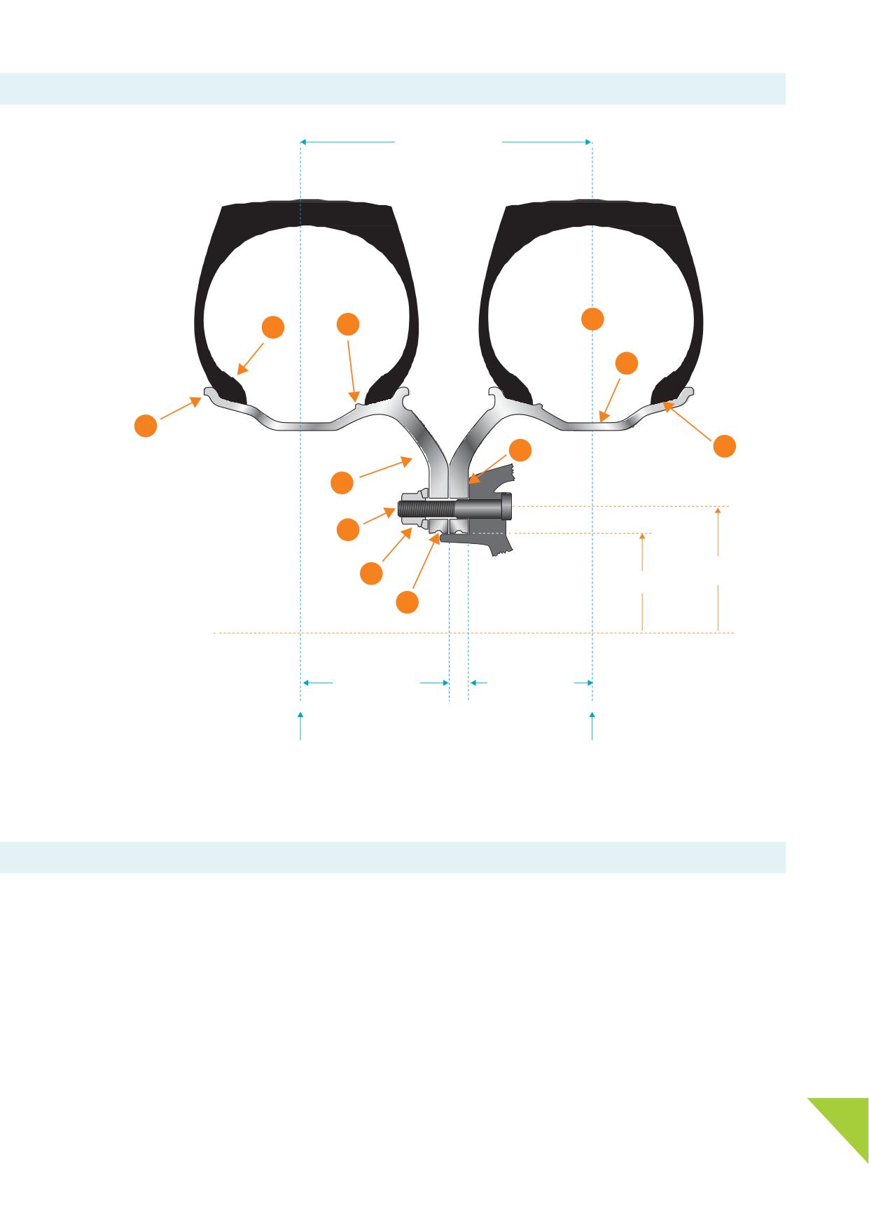
16.b. Common terms
Dual spacing
9
2
3
10
1
11
8
4
1. Rim fl
2. Tyre bead
3. Safety hump
5
4. Disc area
5. Stud
Bolt circle
6.
2-Piece fl
nut
6
Hub bore
7. Hub bore groove
7
8. Mounting face
9. Air chamber
10. Drop centre
11. Bead seat
Wheel outset
Wheel inset
(HDS, HMA)
(OffS, H ET)
Rim centreline
Rim centreline
Graphic 16-1
16.c. Conversion factors
Inches to Millimetres
Fluid ounces (US) to millilitres
Pounds to Kilograms
Inches x 25.4 = Millimetres
Fl oz (US) x 2.957.353 = millilitres
Pounds x 0.4536 = kg
Millimetres to Inches
Bar to kPa
Kilograms to Pounds
Millimetres x 0.03937 = Inches
Bar x 100 = kPa
kg x 22.046 = Pounds
Millilitres to fl
ounces (UK)
kPa to Bar
Foot-pounds to Newton Meters
ml x 0.035195065 = fl oz (UK)
kPa x 0.01 = Bar
Ft-lbs. x 135.582 = Nm
Fluid ounces (UK) to millilitres
psi to kPa
Newton Meters to Foot-pounds
Fl oz (UK) x 2.841.307 = millilitres
psi x 68.948 = kPa
Nm x 0.737562 = Ft-lbs.
Millilitres to fl
ounces (US)
kPa to psi
16
ml x 0.03381402 = fl oz (US)
kPa x 0.145 = psi
99