MT86H Off-Highway Dump Truck. Operation and Maintenance Manual (2017)
Operation and Maintenance Manual
MT86H
Off-Highway Dump Truck
WARNING
Before operation and maintenance, the
drivers and service personnel shall always
read and get understanding of the manual.
Otherwise, fatal accident may occur. This
manual shall be kept properly for future
reference by the personnel concerned.
LINGONG GROUP JINAN HEAVY MACHINERY CO., LTD
MT86H Off-Highway Dump Truck Operation and Maintenance Manual
880*1230 mm sextodecimo
8 printed sheet
3rd edition and printed for the first time in May 2018
LINGONG GROUP JINAN HEAVY MACHINERY CO., LTD
Add: F12,Building 3 LushangGuoao Plaza, 9777 Jingshi Road,Lixia District,Jinan, Shandong,
250000,China
Tel: 86-0531-81663345
Technical service: 86-0531-81666372
Fax: 86-0531-81666853
Accessory sales: 86-0531-67605016
Web: www.lgmg.com.cn
Contents
Foreword
IV
Chapter I Safety
1
1.1 Basic precautions
3
1.2 Operation precautions
4
1.3 Other precautions
5
1.4 Notices&signs and their pasting positions
6
Chapter II Product Introduction
11
2.1 Outline and component name
13
2.2 Outline dimension
13
2.3 Application
14
2.4 Work Environment Requirement
14
2.5 Vehicle parameters
14
Chapter III Operation
17
3.1 Door operation
19
3.2 Cab interior device
21
3.3 Cab exterior devices
31
3.4 Cab suspension
34
3.5 Cab tilting
35
3.6 Preparation before driving
37
3.7 Start-up and gearshift
46
I
3.8 Operation at low temperature environment
49
3.9 Wheel replacement and tire pressure
51
3.10 Running-in of new vehicle
53
Chapter IV Operation and Maintenance of Main Assemblies
55
4.1 Operation and maintenance of engine
57
4.2 Operation and maintenance of intake system
60
4.3 Operation and maintenance of clutch control system
63
4.4 Operation and maintenance of transmission
74
4.5 Operation and maintenance of front axle
82
4.6 Operation and maintenance of suspension system
92
4.7 Operation and maintenance of steering system
103
4.8 Operation and maintenance of brake system
111
4.9 Operation and maintenance of A/C
125
Chapter V Maintenance
135
5.1 Mileage for routine inspection & maintenance interval
137
5.2 Details on mandatory maintenance of MT86 mining off-highway off-highway
dump truck
137
5.3 Key points of maintenance
139
Chapter VI Annex
153
6.1 List of bulbs
154
6.2 List of quick-wear parts of electrical system
154
6.3 Schematic diagram of brake
155
II
6.4 Principle of hydraulic system
156
6.5 Schematic diagram of electrical system
157
III
Foreword
Thanks for choosing mining dump trucks manufactured by Lingong Group Jinan Heavy
Machinery CO., LTD., Ltd. This manual describes the mechanism, driving and operating,
maintenance and adjustment, technical parameters and service/adjustment data of the MT86H series
mining dump trucks.
Maximizing the profits from your Off-Highway Dump Truck is our common goal, which is to a
large extent dependent on your familiarity with the truck and a careful and thorough maintenance.
We sincerely hope that you can read through the manual prior to the first start, operation as
well as maintenance and service of the truck and get full understanding of the operations and
maintenances described herein.
All the pictures and descriptions covered herein are correct at time of publication; but
the structures and performances of our products are constantly improved and perfected; therefore,
please understand that the related design, operation and maintenance instructions are subject
to change at any time without prior notice. For the latest information on the dump truck or in
case of any doubts about this manual, please consult LGMG.
This manual is applicable for MT 86H series Off-Highway Dump Truck (standard configuration).
Users shall be in strict accordance with the mileage or time interval in the maintenance schedule
to do maintenance to the assembly and the dump truck.
The manual is a part of the dump truck and thus shall be handed over together when transferring
the ownership or the right of the truck. If the manual is lost, damaged or hard to be recognized,
please replace it in time.
The copyright of this manual is reserved by Lingong Group Jinan Heavy Machinery CO.,
LTD., Ltd. Reproduction or reprinting without written permission by LGMG is prohibited.
IV
!
WARNING
● Only the specially trained personnel with corresponding qualifications are
allowed to operate and maintain the truck.
● Incorrect operation, maintenance and repair are dangerous, and may lead to
personal injury.
● Before operation, maintenance or repair, the operator shall carefully read
this manual.
● Loading should be done in strict accordance with the rated loading capacity,
and any consequences due to overloading or unauthorized modification shall be the
responsibility of the users.
● The operating procedures and precautions referred to herein are only
applicable to the stipulated operation of the machine. For any operations out of
the specification but not prohibited, always make sure that this operation will not
hurt you or other people.
V
Safety Attentions
Operators should understand and follow prevailing national and local safety regulations. In case of
no relevant national or local regulation, safety attentions in this manual will be applicable.
Most accidents are caused by failure of following regulations on machine operation and
maintenance. To avoid accident, please read, understand and follow all warning requirement and
notes in the manual and on the machine before operation and maintenance.
Details of safety measures are explained in Chapter I "Safety".
Since it is unable to predict all possible dangers, therefore, safety explanation in the manual and on
the machine may not include all safety precautions. In case of using steps and operation in this
manual, it should be guaranteed that both the operator and others are safe and the operation
would not damage the machine. If the operation safety is uncertain, please consult the company
or dealers.
Precautionary measures on operation and maintenance in the manual are only applicable to using
the machine as specified purposes. If the machine is used beyond the range listed in the manual,
our company will bear no liabilities. All safety liabilities of such operation should be borne by the
user and operator.
Operation prohibited in the manual should not be executed in any circumstance.
Caution signals below are used to indentify safety information in the manual.
! DANGER - If the situation classified as “DANGER” is not avoided, serious injury
or casualties is likely to occur. This word can also be used when the machine may
be seriously damaged if the possible hazard is not avoided.
! WARNING - If the situation to be warned is not avoided, serious injury or
casualties may occur. This word can also be used when the machine may be seriously
damaged if the potential hazard is not avoided.
! CAUTION - If the situation to be noticed is not avoided, minor or moderate injury
may occur. This word is also used when the machine may be damaged or the service life
shortened if the potential hazard is not avoided.
VI
Chapter I Safety
1
2
1.1 Basic precautions
The off-highway dump truck described here
is a kind of mining engineering machinery, which
has quite different structure and working
properties compared to ordinary vehicles;
therefore, the safety precautions and operation
Fig. 1-1
instructions described in this manual shall be
followed prior to the operation.
1) While working together with other
operators or site traffic commander, make sure
that all personnel concerned understand the hand
signals.
2) Always do inspection before or after the
Fig. 1-2
operation, so as to eliminate the potential danger
such as leakage of oil, water and air, bolt
looseness, unusual noise or other hazards that
could cause faults and serious accidents.
3) Never enter or stretch your hands between
the moving components, and avoid any rotating
and moving parts. Do not enter between the
cargo body and the frame when the cargo body is
lowering.
4) Always park the truck on a level ground; if
Fig. 1-3
you have to park the truck on a slope, wedge it
with cushion blocks. In this case, please stop the
truck with foot brake, set the transmission control
lever to NEUTRAL or REVERSE position, apply
3
the hand brake, lower down the cargo body,
shut down the engine and remove the key.
5) Do not place the inflammables and
explosives near the hot parts like turbocharger,
exhaust pipe, muffler and radiator for fear of fire
or other accidents. Before touching the above
parts, make sure that those parts are cooled
Fig. 1-4
down to avoid scald.
1.2 Operation precautions
1) Do not jump up/off the off-highway dump truck
directly, and please get on/off the truck by the
ladder or grip only.
Getting on/off the running truck is prohibited.
2) During normal running, such dangerous driving
Fig. 1-5
behaviors as sudden braking, fast travelling,
sharp turning at a high speed or driving in a
zigzag are not allowed.
3) Before starting the truck, always inspect if the
followings have been done:
● The parking brake is applied;
● The transmission is set to NEUTRAL position;
Fig. 1-6
● The PTO is disengaged.
4) When the truck is working, the operator shall sit
in driver’s seat to do all operations. Operating or
driving in other places than the driver’s seat is
prohibited.
5) When driving on a slope, pay attention to the
change of the truck’s center of gravity.
4
! When driving the truck under full
load on a slope:
● Do not brake the truck abruptly when
driving downhill;
● Never disengage the clutch or coast
Fig. 1-7
the truck at neutral gear when driving
downhill;
● Do not make a sharp turn.
6) When the truck starts running, the cargo body
is tiltable; thus irrelevant personnel wandering
around the truck is dangerous and shall be
Fig. 1-8
prohibited.
1.3 Other precautions
1) Unauthorized modification is not allowed. Any
modification without permission from the
Company may lead to an accident, and users
shall contact with the Marketing Dept. of the
Company in advance. The Company assumes no
Fig. 1-9
liability for the casualties and damages incurred
therefrom.
2) When lifting the cargo body to repair the
components beneath, the stay bar of the cargo
body should be set to a safe position for support,
and restored once the repair is finished.
3) Always inspect the tyre from the side and never
stay before or behind the rotating tyre.
5
4) Repair and replacement of tyre shall be done
by the specialized personnel as it is highly risky.
5) Be careful when doing welding around the tyre,
to avoid accidents due to tyre explosion.
6) When welding the truck for repair, always turn
off its master power switch. Do not perform
electric welding or flame cutting to the pipeline
containing flammable liquid. Make sure to clean
with non-inflammable liquid before such
operations.
7) Always lower the cargo body to the subframe
before leaving the truck unattended, and check
that the lifting control lever is in the center, the
parking brake is applied and the transmission
control lever is set to the NEUTRAL position, and
then shut down the engine.
1.4 Notices&signs and their pasting
positions
1) Engine repair Caution: beneath the cab
instrument panel.
6
2) Hydraulic oil mark: at hydraulic oil tank.
3) Fuel tank filling notice and sign: at fuel tank.
4) Lifting notice & sign: at the underpart of the
hydro-cylinder support.
5) “No treading” sign: on battery box and fuel
tank.
7
6) “High temperature” sign: near the muffler.
7) “Working safety” signs: at front end and in the
middle of the cargo body.
8) Buffer tank operation Caution: beside the
buffer tank.
9) Air reservoir Caution: at the external wall of the
air reservoir.
10) Travelling Caution: at the left upper corner of
front windshield. (LHD)
8
11) Travelling Caution:(1):at the front part
windshield.
12) Travelling Caution:(2):at the front part
windshield.
13) hydro-cylinder notice:at the right front side of
the seat in cab.
14) Parking brake handle valve notice:at the left
front part of the Parking brake handle valve.
9
10
Chapter II Product Introduction
11
12
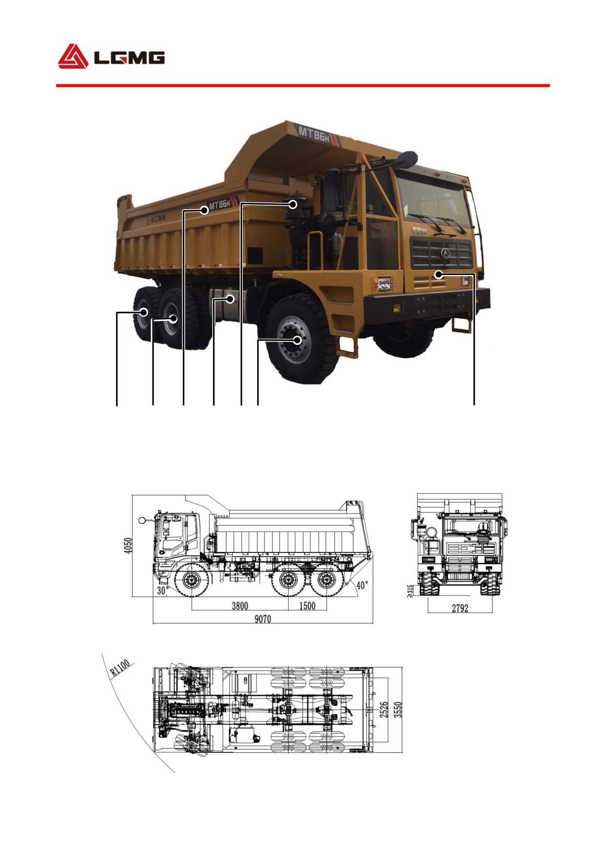
2.1 Outline and component name
1
2
3
4
5
6
7
1.Rare drive axle 2.Middle drive axle 3.Cargo 4.Fuel tank 5.Air filter 6.Streeing axle 7.Cab
2.2 Outline dimension
13
2.3 Application
As an off-highway dump truck featuring open cargo body, this machinery is suitable for loading/unloading and
transportation of earth-stones and minerals at ports, docks and various engineering sites, but in no case shall it
be used for works and operations on road,loading/unloading or transportation of combustibles and explosives,
and operations under ground or in environments containing explosive medias.
! WARNING:
● The truck is an off-road dump truck and should not be used on the road.
● When using the truck, please load the truck strictly in accordance with the
standard load limited by the truck. Overloading is prohibited.
● The truck may be used to transport solid materials only. It is strictly
prohibited to load or transport flammable and combustible materials with the truck.
2.4 Work Environment Requirement
The truck is applicable to the following environments:
Item
Altitude
Environment temperature
Fording depth
Parameter
≤4000m
-15℃~+40℃
≤315mm
requirement
The truck is a common engineering machine which could be used for various applications in
normal circumstances described in the manual. In case of being used for other purposes or in
environment of potential hazards such as inflammable or explosive air or regions containing
asbestos dusts, special safety requirements must be followed. Devices of corresponding
applications must also be supplied to the machine.
2.5 Vehicle parameters
2.5.1 Vehicle performance parameter
Items
Parameters
Items
Parameters
Max. total mass (kg)
86000
Overall dimension (mm)
9070×3550×4050
Max. vehicle speed (km/h)
38
Max. gradeability (%)
29
Volume of cargo body
31
Min. turning diameter (m)
≤22
(paperbacked) (m3)
Q/1300LGJ004-2015
Kerb weight (kg)
30700±100
Product standard
《off-road dump truck》
14
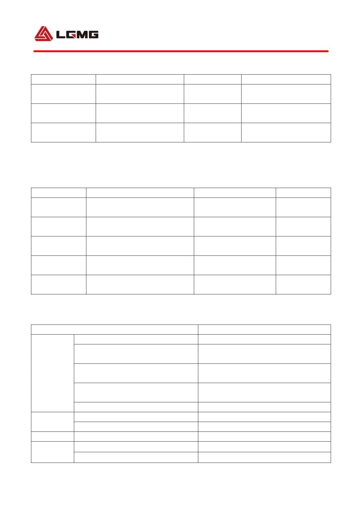
2.5.2 Main dimensions
Items
Parameters
Items
Parameters
2792 (front axle)
3800 (Front-middle)
Track width (mm)
Wheelbase (mm)
2526 (rear axle)
1500 (Middle-rear)
Departure angle
Approach angle (°)
30
40
(°)
Min. ground
≥315
No. of axles
3
clearance (mm)
2.5.3 Engine
Items
Parameters
Items
Parameters
Inline, DI, water-cooled,
Type
No. of cylinders
6
supercharged and inter-cooled
Rated power
309
Bore/stroke (mm)
126/155
(kW)
Rated speed
Min. fuel-consume ratio
2200
-
(r/min)
(g/kW.h)
Displacement
11596
Max. torque (N.m)
1750
(mL)
Emission
Consumption rate of
ChinaⅡ GB20891-2007
-
standard
engine oil and fuel
2.5.4 Transmission system
Items
Parameters/contents
Type
Single-disc, dry, hydraulic remote-operated
Release travel at separated finger end of
12-14
diaphragm spring (mm)
Friction plate outside diameter/inside
Clutch
430/242
diameter (mm)
Max. release force at separated finger
8600
end of diaphragm spring (N)
Release fork lever ratio
1.73
Type
Fixed-shaft
Transmission
Transmission gear
7 forward gears and 1 reverse gear
Front axle
Non-driving steering axle
Welded axle housing
Main decelerate ratio
3.7
Drive axle
Final decelerate ratio
3.478
15
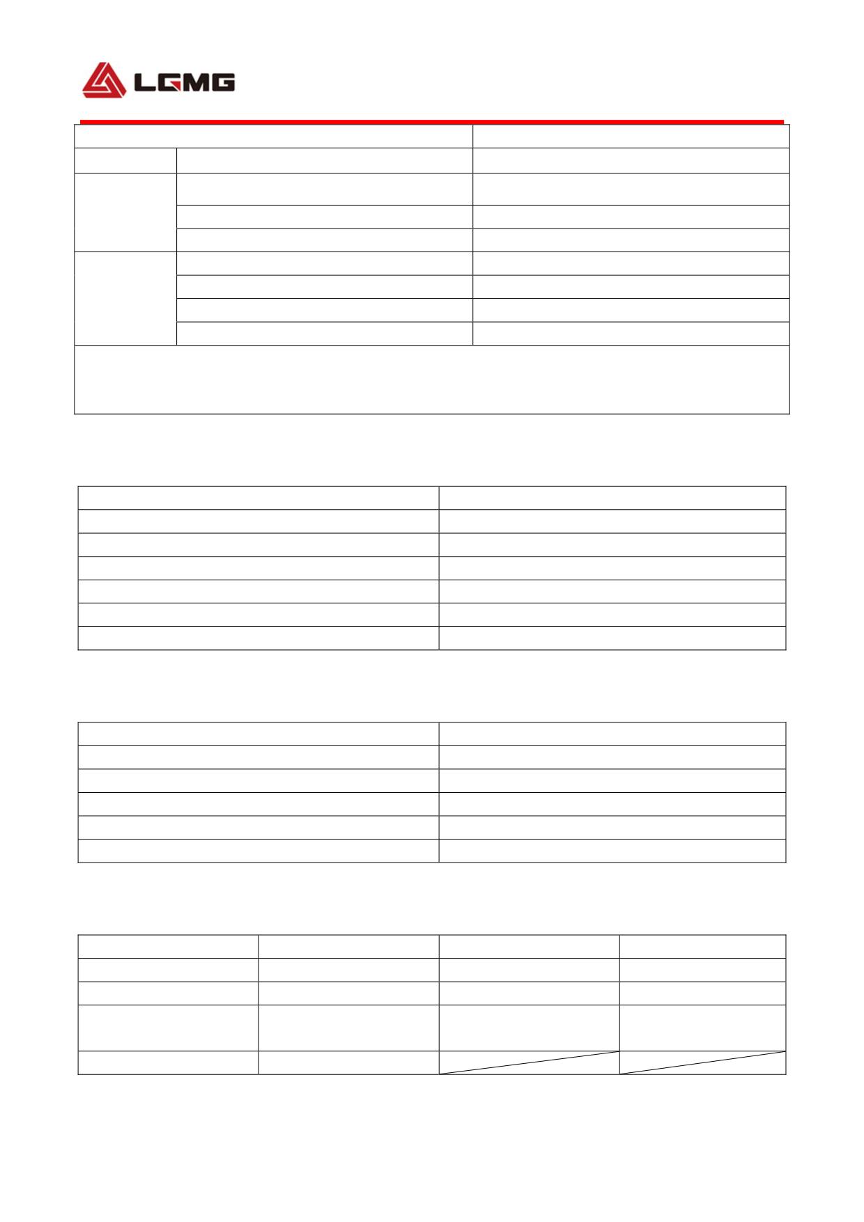
Items
Parameters/contents
Total decelerate ratio
12.87
Wheel rim spec.
10.0/2.0-25
Wheel
Tire spec.
14.00R25
Tire pressure (MPa)
0.85
Brake pressure (MPa)
0.85
Brake system main brake
Pneumatic, dual-circuit
Brake system
Brake system auxiliary brake
Engine exhaust emission brake
Brake system parking brake
Spring brake & emergency brake
NOTE: All wheel rims shall be subject to the same specification. The tire pressure value indicated in
the table is factory air pressure (no load), and the actual air pressure shall be adjusted according to
“Comparison table of speed, load and air pressure” in 3.9.
2.5.5 Steering system
Items
Parameters/contents
Type
hydraulic steering
Max. turning angle
38°
Safety valve
I/A
Steering pump
Vane pump: displacement28ml/r
Min. turning diameter (m)
22
System working pressure (Mpa)
17
2.5.6 Working device
Items
Parameters/contents
Type
pneumatic control
Maximum working pressure
24Mpa
Lifting time of cargo body (full load)
≤25s
Descending time of cargo body (empty bucket)
≤25s
Total time
≤50s
2.5.7 Reference fill capacity
Items
Parameters
Items
Parameters
Fuel
530L
Engine oil
24L
Hydraulic oil
135L
Transmission
23L
Axle (for main driving
46L (intermediate axle)
Brake system
1.5L
and final drive)
37L (rear axle)
Antifreeze
50L
16
Chapter III Operation
17
18
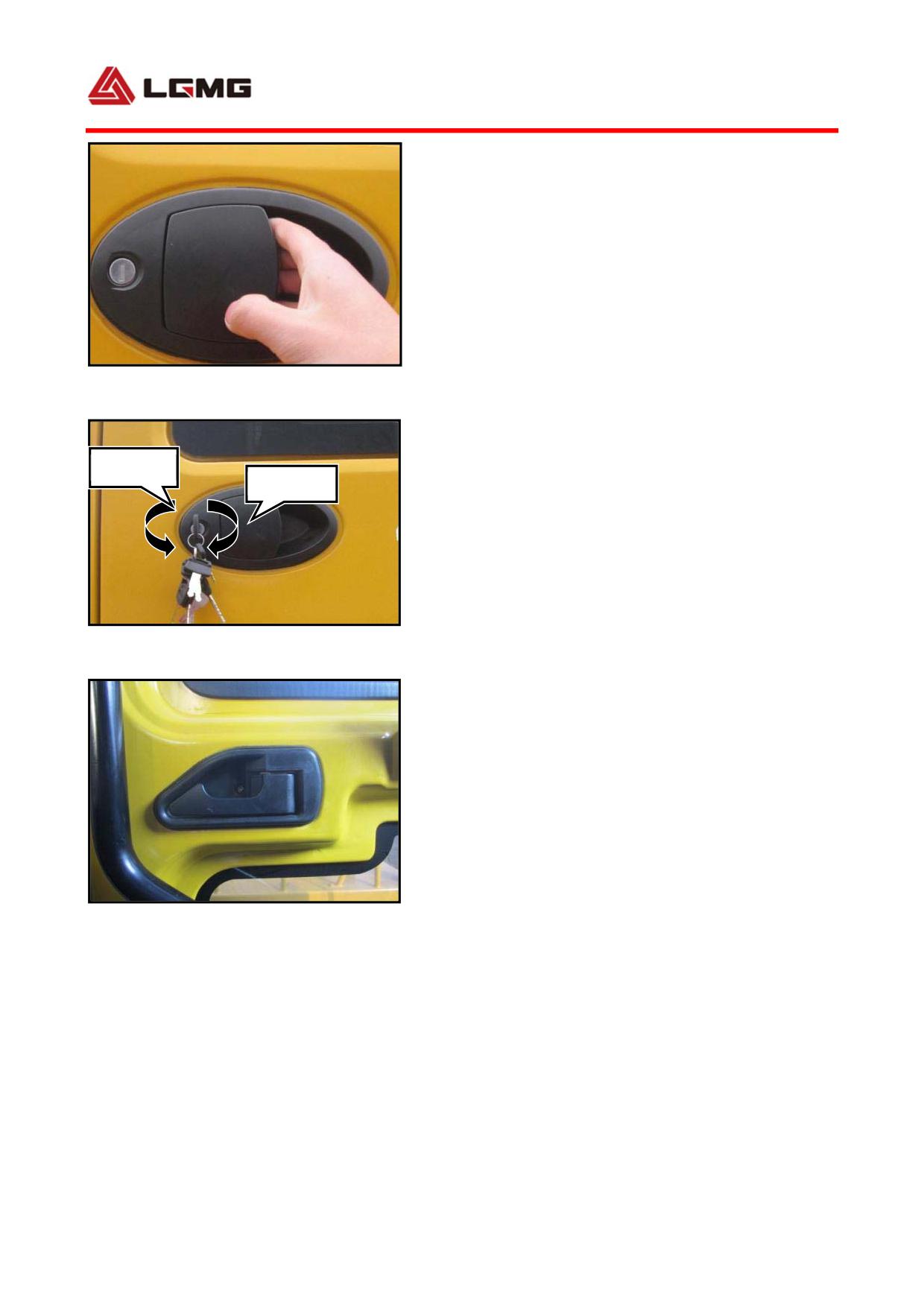
3.1 Door operation
! WARNING: Do not drive unless all
doors are properly closed!
3.1.1 Use door switch outside
Door opening: When the door is unlocked, lift
Fig.3-1
the handle and pull it outward (as shown in Fig.
3-1) to open the door; when the door is locked,
Unlock
lock
insert the key in, turn it anticlockwise for
180º (as shown in Fig. 3-2), lift the handle
and pull it outward to open the door.
Door closing: Close the door directly.
Door locking: After the door is closed, insert
Fig.3-2
the key in, turn it clockwise for 180º, and pull
out the key; or before the door is closed,
insert the key in, turn it clockwise for 180º
and close the door.
After the door is locked, the door could not
be opened by pull the handle outward.
3.1.2 Use door switch inside
Fig.3-3
Door opening: Pull the door push button (as
shown in Fig. 3-3) and push the door open.
Door closing: Close the door directly.
! CAUTION: While leaving the vehicle,
19
always make sure that the window and door
are closed and the door is locked. Please
keep valuables with you, rather than
leave it behind in the cab.
20
3.2 Cab interior device
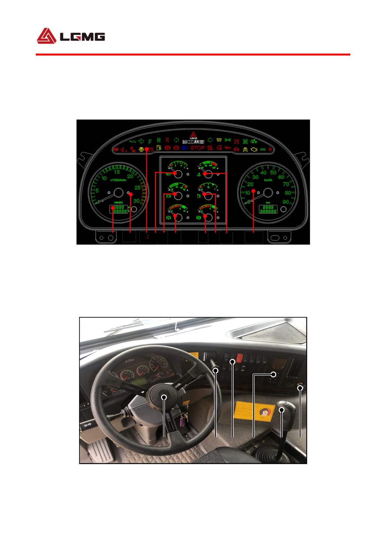
3.2.1 Instrument cluster
1
2
3 4
5
6
7
8
9
10
Fig.3-4
1. Mileage & travel time display screen
2. Engine tachometer
3. Alarm indication mark
4. Oil pressure
gauge
5. Voltmeter
6. Barometer of brake circuit 1
7. Barometer of brake circuit 2
8. Fuel gauge
9. Coolant thermometer
10. Speedometer
3.2.2 Steering wheel and switch panel
1
2
3
4
5
6
1. Steering wheel 2. Hand brake valve handle 3. Rocker switch
4. Air-condition operation panel
and display screen 5. Transmission gear shift handle
6. Cigarette lighter
21
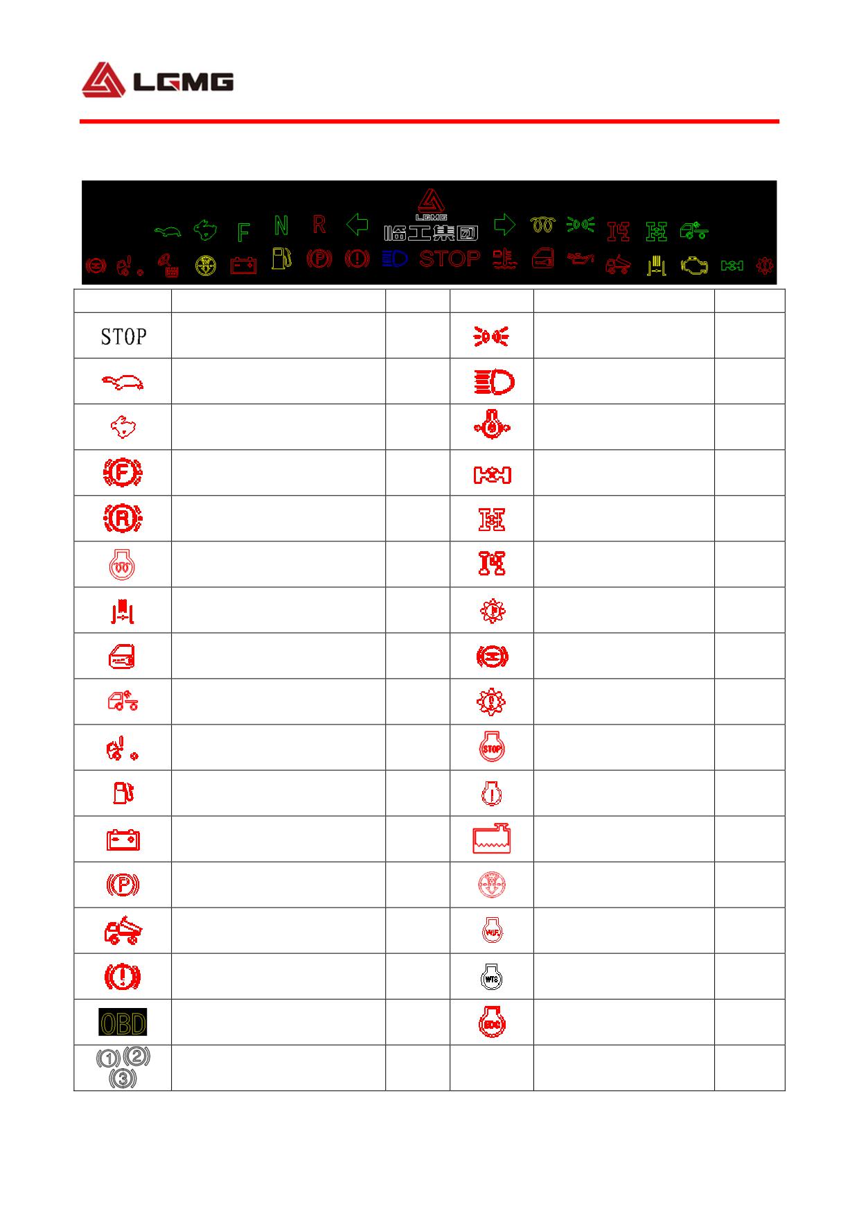
3.2.3 Alarm indicators
S/N
Description
Color
S/N
Description
Color
Width lamp on
Parking indicator
Red
Green
indicator
Low gear indicator
Green
High beam indicator
Blue
(reserved)
High gear indicator
Low oil pressure alarm
Green
Red
(reserved)
indicator
Forward gear indicator
Inter-wheel differential
Green
Green
(reserved)
indicator (reserved)
Reverse gear indicator
Bogie differential lock
Red
Green
(reserved)
indicator
Left turn indicator indicator
Yellow
Parking PTO indicator
Red
(reserved)
Transmission high
Exhaust brake indicator
Yellow
Red
temperature indicator
Retarder brake
Door ajar alarm indicator
Red
Red
indicator (reserved)
Rear working lamp on
Transmission fault
Green
Amber
indicator
indicator (reserved)
Cab unlocked alarm
Engine serious fault
Red
Red
indicator (reserved)
indicato
Low fuel level alarm
Engine fault indicator
Yellow
Red
indicator
(reserved)
Storage battery charging
Engine coolant level
Red
Red
indicator
low alarm indicator
Air filter blockage
Parking brake indicator
Red
Yellow
indicator
Cargo lift alarm indicator
Red
Water in oil indicator
Yellow
Low brake pressure alarm
Engine start wait time
Red
White
indicator
indicator
Engine diagnostic
OBD indicator
Yellow
Red
indicator
Retarder position indicator
Red
22
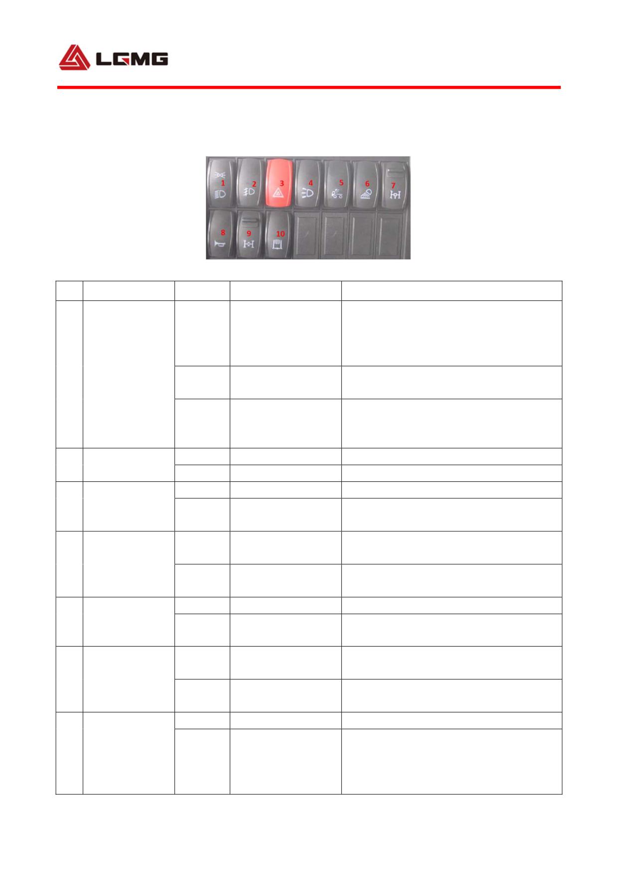
3.2.4 Summary of rocker switch marks and function description (The key switch will be
ineffective when it is set to gear 1, unless otherwise specified.)
3-7
S/N
Name
Condition
Function
Remarks
When the switch is turned to gear 2 and
Clearance lamp ON /
3, the instrument lighting actuation will
1
headlamp OFF
be effective; and high beam inching will
be ineffective.
1
Lamp switch
Clearance lamp and
0
headlamp OFF
High beam inching will be effective; high
clearance lamp /
2
beam/low beam combination switch will
headlamp ON
be effective.
Front fog lamp
0
Front fog lamp OFF
2
switch
1
Front fog lamp ON
0
Hazard warning OFF
Hazard warning
3
The key switch will be effective when it is
switch
1
Hazard warning ON
turned to gear 1, 2, 3 and 4.
Front working lamp
0
Front working
OFF
4
lamp switch
Front working lamp
1
Front working lamp driven
ON
Cab rear
0
OFF
5
working lamp
1
ON
Cab rear working lamp ON
switch
Rear working lamp
0
Rear working
OFF
6
lamp switch
Rear working lamp
The side working lamp is also controlled
1
ON
by this switch.
0
OFF
PTO solenoid valve actuated; when PTO
Parking PTO
7
and switch are set to proper positions, the
switch
1
ON
corresponding indicator lamps on the
instrument will be on.
23
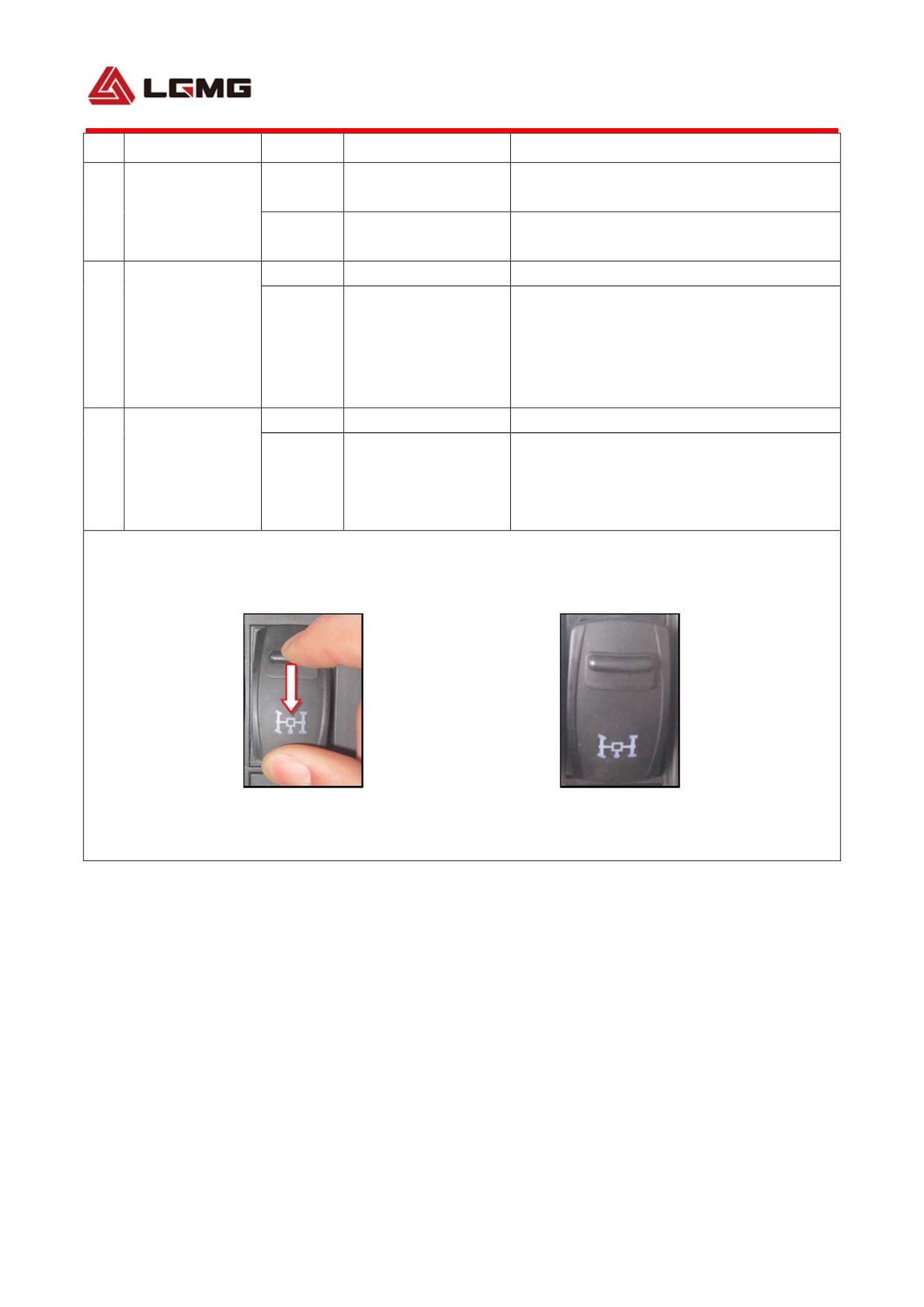
S/N
Name
Condition
Function
Remarks
Electric horn
Press down horn on the steering wheel,
Horn
0
selected
and it will work.
8
change-over
Press down horn on the steering wheel,
switch
1
Air horn selected
and it will work.
0
OFF
Inter-axle differential solenoid valve
Inter-axle
actuated; when inter-axle differential
9
differential
1
ON
switch is set to proper position, the
switch
corresponding indicator lamp on the
instrument will be on.
0
OFF
Exhaust butterfly valve closed, EVB starts
Exhaust brake
10
to work, the green instrument indicator is
switch
1
ON
on, the operating cylinder works, and the
engine flames out.
NOTE: The rocker switch with striker has an anti-mistrigger function. It cannot be moved unless the
striker is pulled down; and it will auto reset as long as the striker is released. See figures below for
operation.
Pull down the striker, and
Release the striker, and it
meanwhile, move the switch
will automatically reset
24
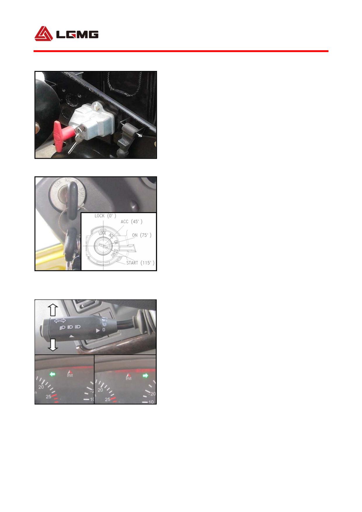
3.2.5 Power switch
1) Main power switch
The main power switch is located outside the
battery compartment of frame side rail.
! CAUTION: If a vehicle will not be
driven for a long time, please turn off
Fig 3-8
the main power switch for the avoidance
of accident. After the engine stops and
the key switch is set to LOCK position,
turn off the main power switch.
2) Key switch
Arrange the key switch to the steering column.
Position
Usage Remarks
Fig 3-9
1(LOCK) Power off the vehicle.
The key can
be pulled out at this time.
2(ACC) Power on consumers when the vehicle is
parked.
3(ON) Driving position
4(START)
Start the engine
Auto reset
to ON gear
3.2.6 Combination switch handle
Fig 3-10
1) Steering lamp operation:
Horizontally move the combination switch handle
forward to turn on the right turn signal
25
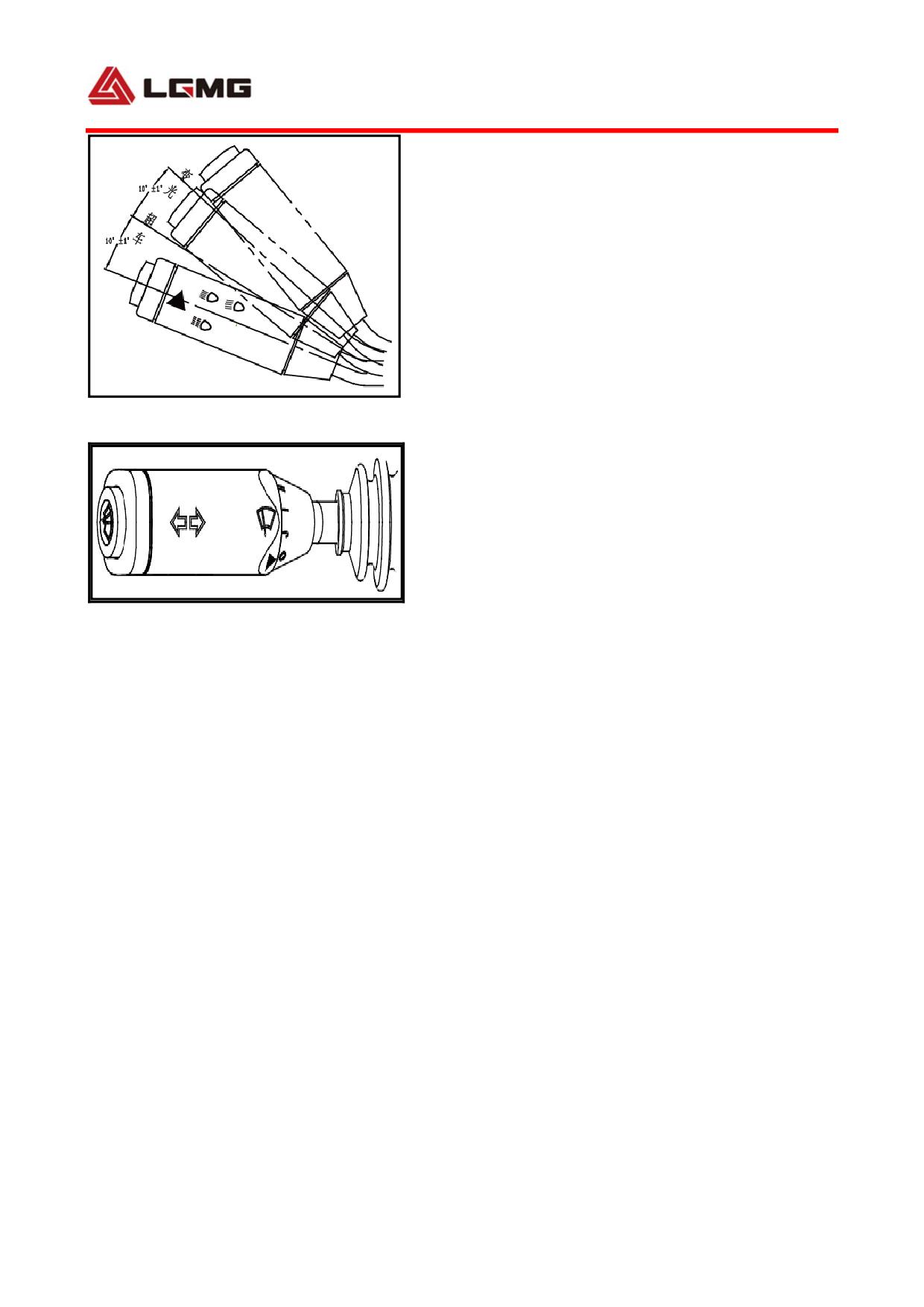
lamp; and horizontally move it backward to turn on
the left turn signal lamp.
When the key switch is set to position 3, move
the handle to turn on the turn signal lamp, and
then a prompt will be heard; when the key switch
is set to position 1 and 2, move the handle to
turn on the turn signal lamp, and then a prompt
will not be heard.
Fig 3-11
2) Headlamp operation:
When the combination switch handle is set to
neutral position, key switch to position 3 and
rocker switch to position 2, the low beam or
high beam will be on. At this time, lift the
Fig 3-12 Press windshield washing system
combination switch handle upward for 4°, and
0-Closed position
J-- Wiper IHT
I-- Wiper low gear II-- Wiper high gear
then high beam and low beam will be both on
(applied for instant lighting for overtaking
or meeting); lift the handle for another 10°
for dimming (high beam to low beam or vice
versa). Release the handle, and it will be
automatically reset.
During daytime overtaking and meeting, lift
the handle upward for 4°, and the high beam
will be on; release the handle, and it will be
automatically reset.
3) Wiper operation
Turn the combination switch to select the
required swing gear for wiper.
26
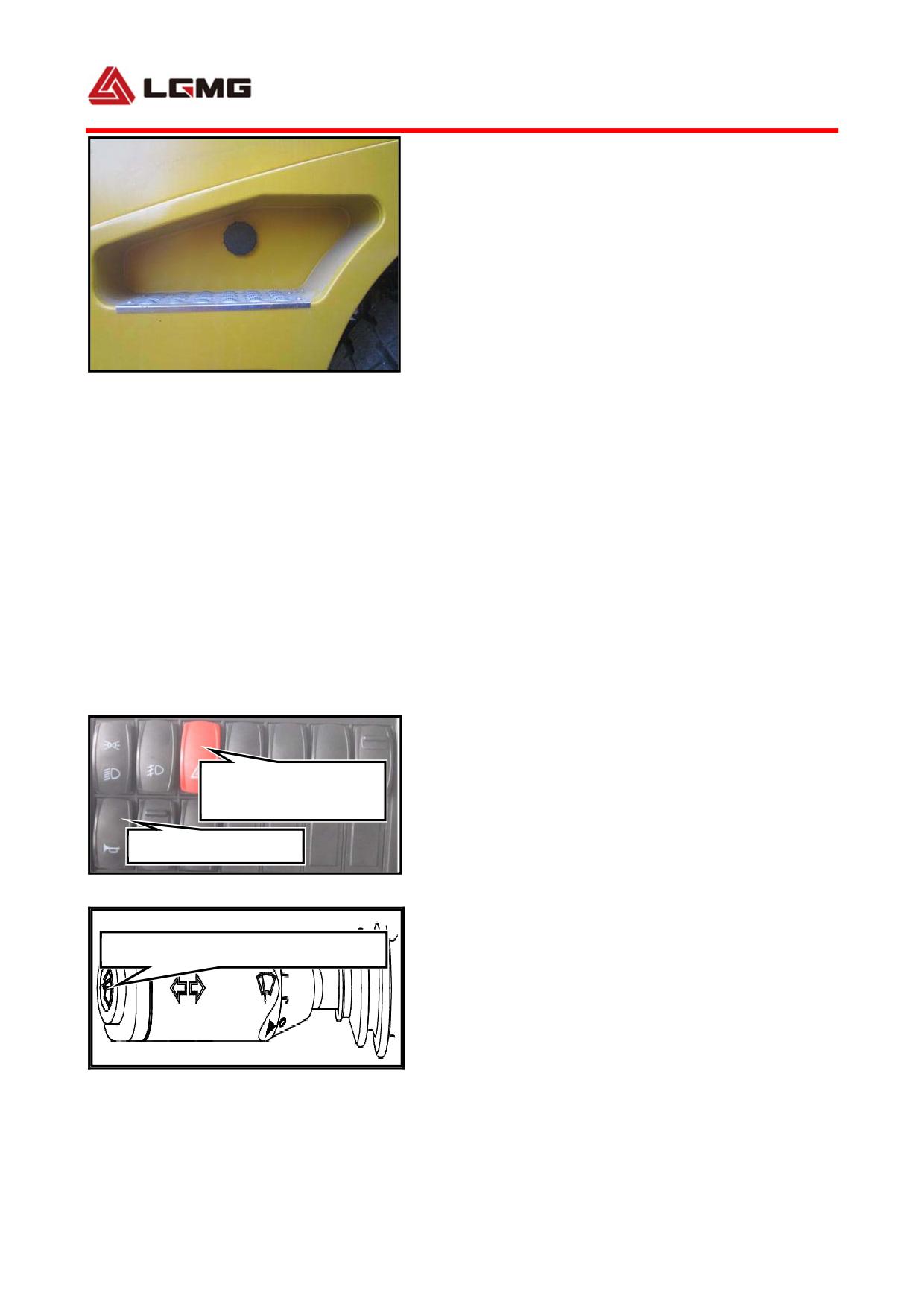
Press and hold the windshield washer button,
and the water jet on wiper blade will inject
glass cleaner, and meanwhile, the wiper will
automatically start working at low gear; water
injection will be stopped after the release.
The glass cleaner filler port is located inside
Fig 3-13
the cab left ladderway.
! CAUTION: Always fill the washer via
the filler port with the specialized
glass cleaner instead of plain water or
other cleaning agent for windshield
washing.
3.2.7 Commonly-used switch operation
1) Hazard alarm
Turn on the main power switch and press down
Hazard warning
switch
the hazard warning switch, and all turn signal
Trumpet switch
lamps and turn signal indicators will flash.
Fig 3-14
2) Horn Button
The truck is provided with an electric horn and
Electronic control gas horn button
an electrically controlled air horn, both of
which are switched by a horn change-over
switch.
Fig 3-15
The horn button is set on the combination
switch. Switch off the air horn switch, and
then press the horn button on the combination
27
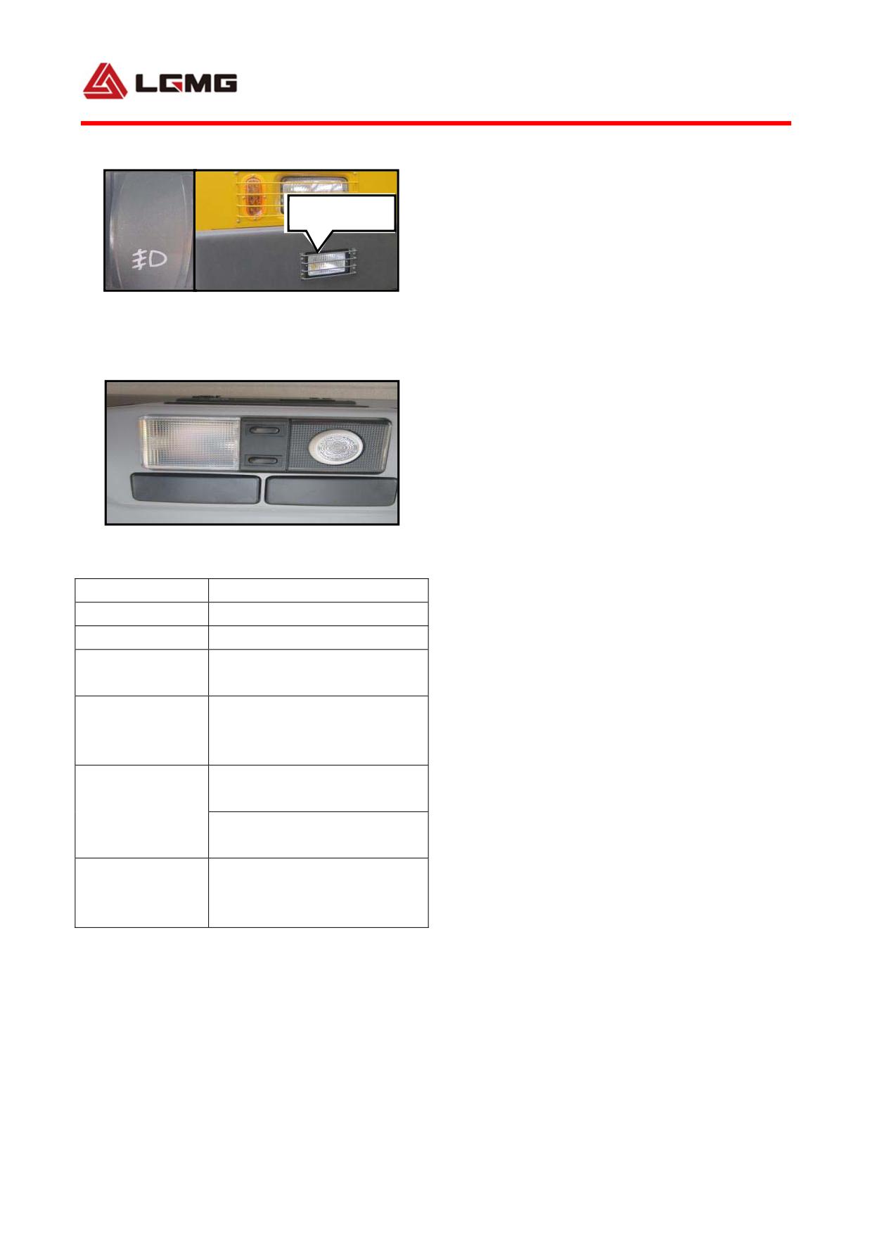
switch, to use the electrically controlled air
horn.
Fog lamp
3) Fog lamp operation
Press down the front fog lamp switch to power
on the front fog lamp. Pull the switch, and then
Fig 3-16
the fog lamp will be off.
4) Interior lighting
After the battery box switch is turned on and
the interior ceiling lamp switch is pushed to
one side (both the right and left are ok), the
interior lighting lamp will be on and off (as
Fig 3-17 Interior lighting
shown in left figure).
Items
Parameters
3.2.8 Seat
Seat width
510mm
Seat height
855mm
Height
The seat is designed for construction
0~40mm
adjustment
machinery and mining dump truck. The seat top
Front/rear
adjustment
180mm
and shock absorber are designed under full
travel
consideration of driver’s safety and comfort
0-70°
(backward
in
Backrest angle
relationship to plumb line)
based on kinematics.
adjustment
0-40°
(forward
in
relationship to plumb line)
The seat backrest designed as luxurious high
Adjustment
backrest applies the latest principle of human
range of driver’s
50~110kg
weight
environmental science and human kinetics to
effectively support the driver’s shoulder,
thus relieving the fatigue.
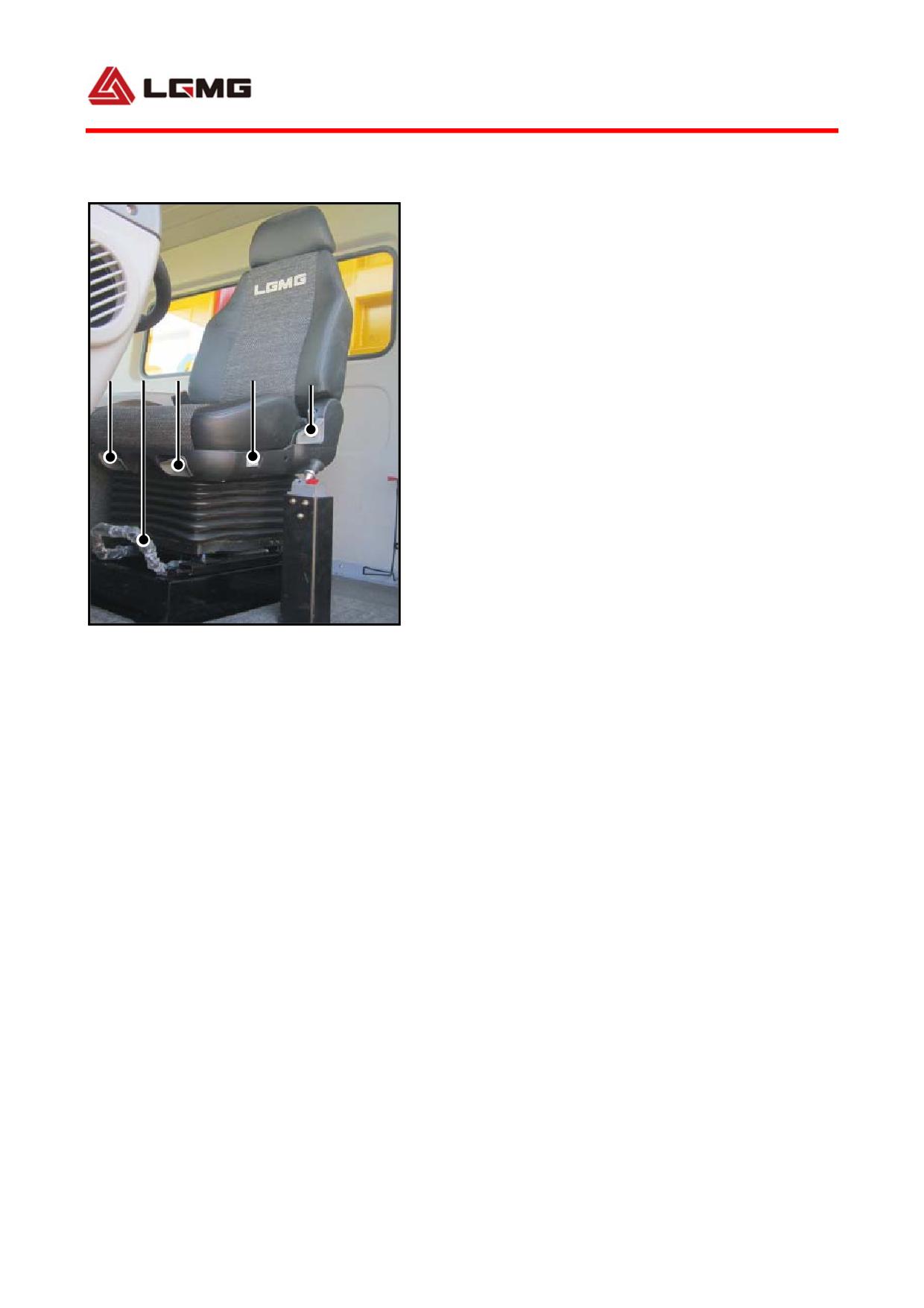
Seat adjustment method:
1) Backrest elevation adjustment: move handle
upward forcibly, turn the backrest to the
28
required angle and release the handle to lock
the backrest.
Range:0~60mm。
2) Horizontal adjustment: pull handle 2 upward
to move the seat forward and backward to the
required position, and release the handle to
1
2
3
4
5
lock.
Range:Forward 80mm,Backward 80mm。
3) Front height adjustment: move handle upward
gently to exert to or relieve from the front
end of cushion upwards or downwards an
appropriate force to lower (lift) it to the
required position, and release the handle to
Fig 3-18 Seat adjustment handle
lock.
Range:0~60mm。
4) Load weight adjustment: rotate front handle
forcibly and adjust it appropriately according
to the driver's weight. The rotation direction
corresponding to weight increase and decrease
is marked on the handle.
Range:40~130 kg。
5)Backrest elevation adjustment: move handle
upward forcibly, turn the backrest to the
required angle and release the handle to lock
the backrest.
Range:40°~180°
! CAUTION: While adjusting the seat
29
backrest, do not lean back too much in
case of hidden danger caused by
triggering rear window.
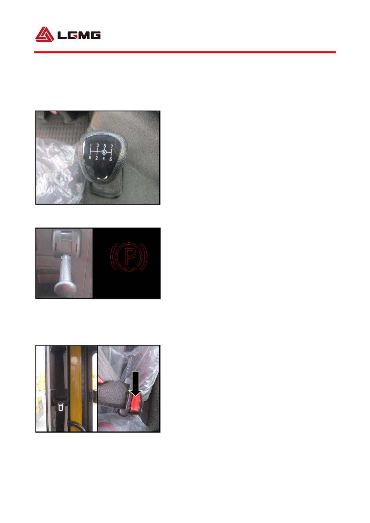
3.2.9 Transmission gearshift lever
The gearshift lever is installed on the engine
hooding. In this way, the disturbance of cab
vibration and the possibility of disengagement
will be eliminated, and the cab tilting will
not be affected.
3.2.10 Hand brake valve (spring parking
Fig 3-19 Transmission gearshift
brake)
The hand brake valve is located at the right
side of seat (The shown brake valve handle is
located at “BRAKE” position). Provided the
parking brake signal lamp is off, the air
Fig 3-20 Hand brake valve lever
pressure will exceed 0.55 Mpa, the spring brake
will get completely loosened, and the vehicle
can get started.
! WARNING: Before the parking brake
signal lamp is off, never start the
vehicle!
3.2.11 Other interior devices
Fig 3-21 Safety belt
1) Seat belt
30
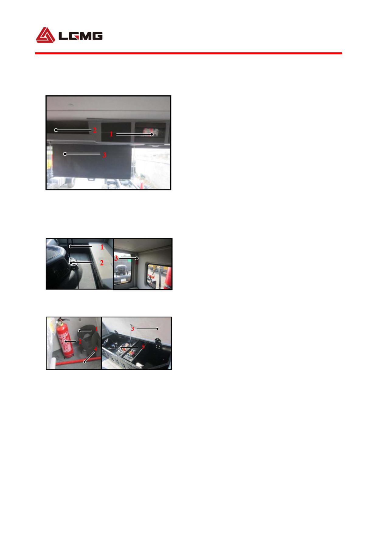
Fastening: Hold the latch of seat belt, wrap
the seat belt around the shoulder and insert
the latch into the striker until a click is
heard.
Unfastening: Press down the red button on the
striker of seat belt as shown by the arrow and
pull out the latch, thus the seat belt will be
automatically reset.
! CAUTION: Always fasten the seat
Fig 3-22
1. Radio and tape player 2. groceries box
belt before driving every time! Check the
3. Abat vent
seat belt for condition and function on
daily basis.
2) Radio and tape player, abat vent and
groceries box (bilateral symmetry).
Fig 2-23
3) Cup holder, escape hammer and handrail
1. handrail 2. Cup holder 3. Escape hammer
4) Thermos bottle thermos bottle, fire
extinguisher, sleeper, pinch bar, electric
appliance cabinet
3.3 Cab exterior devices
Fig 3-24
1. Thermos bottle thermos bottle
3.3.1 Radiator cover
2. Fire extinguisher 3. Sleeper 4. Pinch bar
5. Electric appliance cabinet
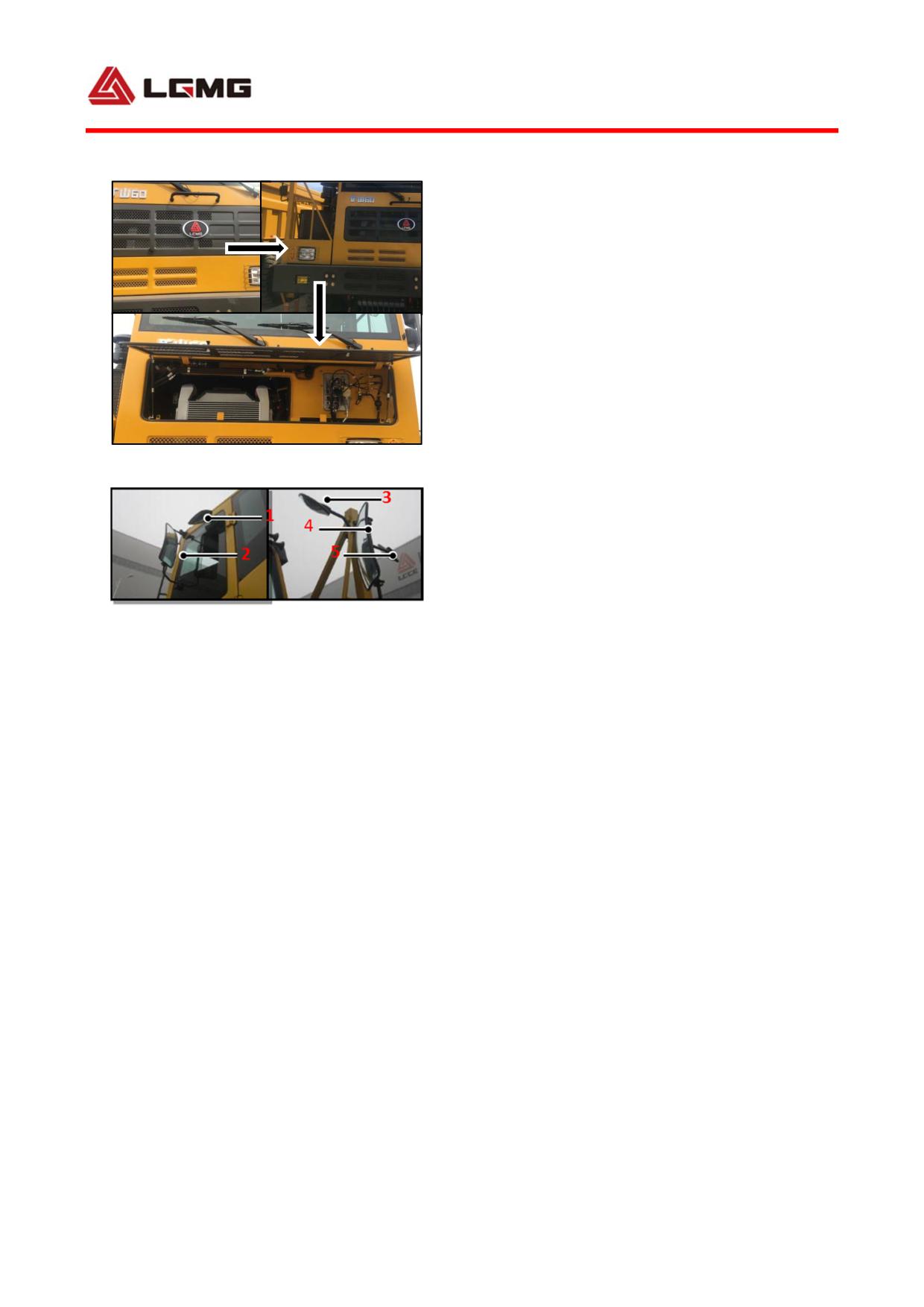
Open radiator cover: rotate the two knobs as
shown in Figure 3-25.
Close radiator cover: pull down the radiator
cover and rotate the knob in reverse.
31
! CAUTION: While closing the cover,
do not apply too much force and make sure
that nobody stays within the travel range
of cover in case of pinch.
3.3.2 Left/right rearview mirrors
They are as shown in Fig. 3-26.
Fig 3-25
Regulation method of rearview mirror in
terrace:
1) The lower edge of the rearview mirror in
terrace is 87 ± 5mm from the upper edge of the
bracket. The distance between the upper and
Fig 3-26
1. Left forestall blind mirror 2. Rearview mirror
lower rearview mirrors is 60 ± 5mm.
3. Right back underview mirror
2) Tighten the fixing bolts of the rearview
4. Main rearview mirror in terrace
5. Right front underview mirror
mirror to be reliable.
3) When fine-tunning the rear-view mirror,
press it upwards, downwards, leftwards and
rightwards.
4) When regulating the rearview mirror and the
main rearview mirror in terrace, open the
rear-view mirror casing, and unscrew 4 fixing
bolts to regulate them to a proper angle, and
then tighten thee bolts in place.
Regulation method of rearview mirror:
1) The distance between the upper and lower
rearview mirrors is 40 ± 5mm, and the lower
32
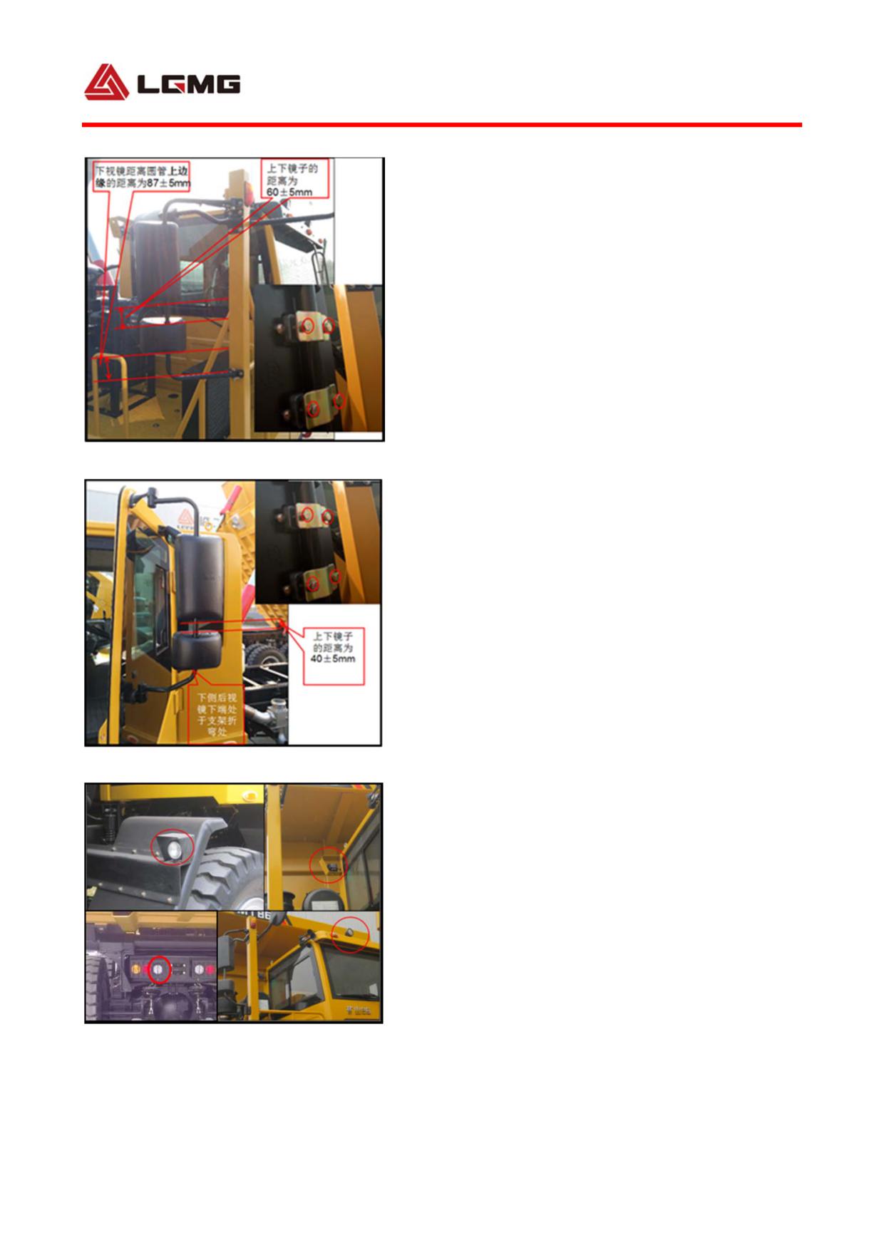
rearview mirror is at the bend of the bracket.
2) Tighten the fixing bolts of the rearview
mirror to be reliable without looseness.
3) When fine-tunning the rear-view mirror,
press it upwards, downwards, leftwards and
rightwards.
4) When regulating the rearview mirror and the
main rearview mirror in terrace, open the
rear-view mirror casing, and unscrew 4 fixing
bolts to regulate them to a proper angle, and
then tighten thee bolts in place.
! Note: When regulate the visual
angle of the rearview mirror, do not
break the rearview mirror with hands; if
necessary, unscrew the fixing bolts to
regulate the visual angle, and then
tighten the bolts, or regulate the glass
angle.
3.3.3 Working lamp
The positions of working lamps are shown in
Fig.3-27: two at the front top of the cab, trail
and front mudguard respectively. They are
Fig 3-27
arranged symmetrically; one at the rear left
of the cab with angle adjustable. The working
lamps are generally controlled by the
33
corre-sponding rocker switch inside, and can
be turned on or off at the same time.
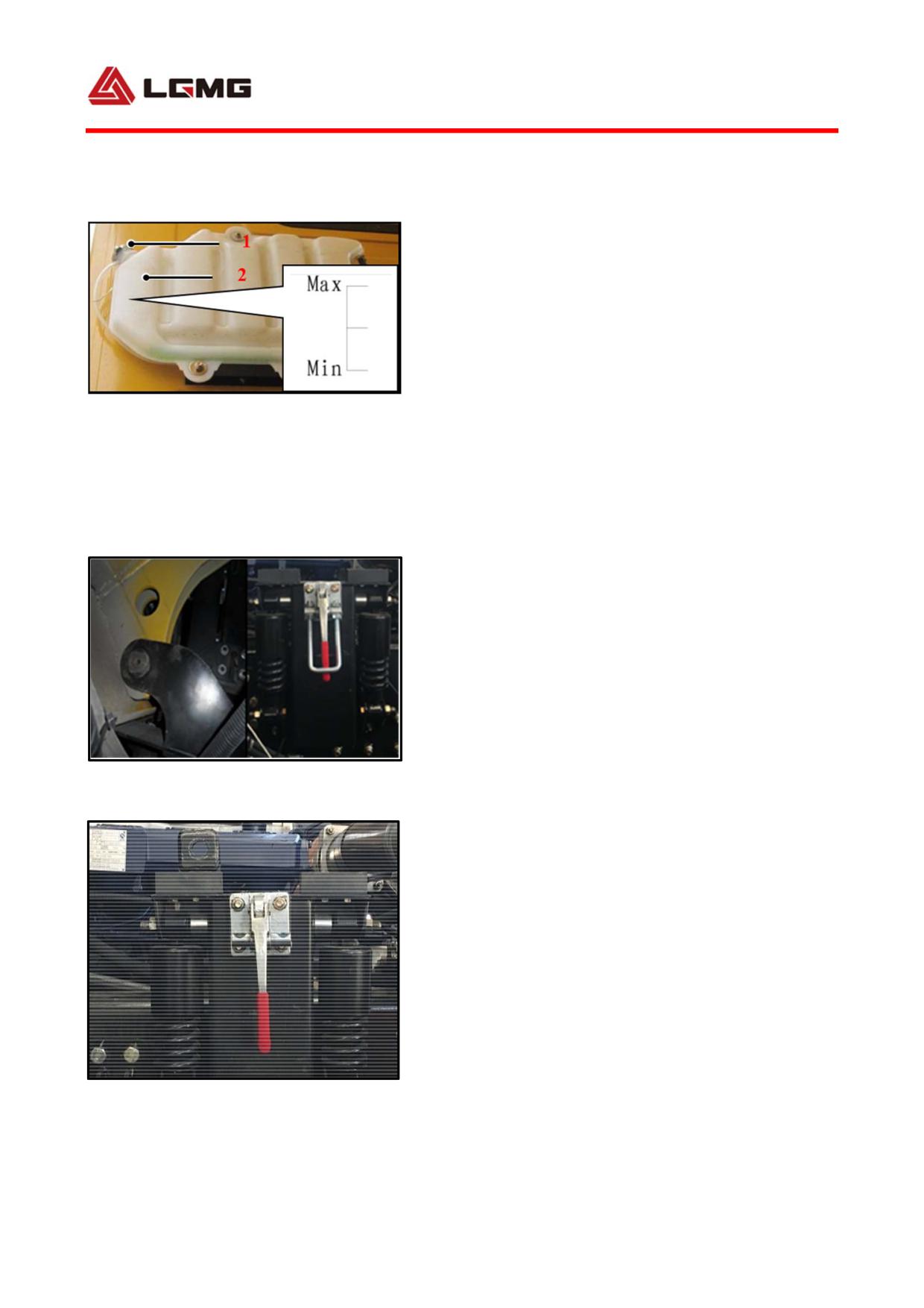
3.3.4 Expansion tank
The expansion tank is located at the rear left
side of cab (as shown in Fig. 3-28).The
pressure relief valve maintains a certain
pressure difference between the internal
Fig 3-28
1. Relief valve
2. Scale
pressure of the cooling system and the
atmospheric pressure, to increase the boiling
point of the coolant. The pressure relief valve
is particularly essential in plateau area, so
do not dismantle and replace it at will!
3.4 Cab suspension
3.4.1 Front suspension
Front suspension Rear suspension
The cab front suspension is applied with the
Fig 3-29 suspension
rotating axle together with rubber shock
absorber.
3.4.2 Rear suspension
Both rear suspensions are applied with dual
shock absorber together with Mechanical lock.
! CAUTION: The interchange or mixture
Mechanical lock
of left and right shock absorbers is not
Fig 3-30
allowed due to their distinct models.
Z
34
3.4.3 Check suspension system
Check if the mechanical lock operates properly.
To prevent the mechanical lock from being
released by vibration of the truck, weld a pin
to the rear suspension, and then insert the pin
from the rear suspension when the mechanical
lock is latched.
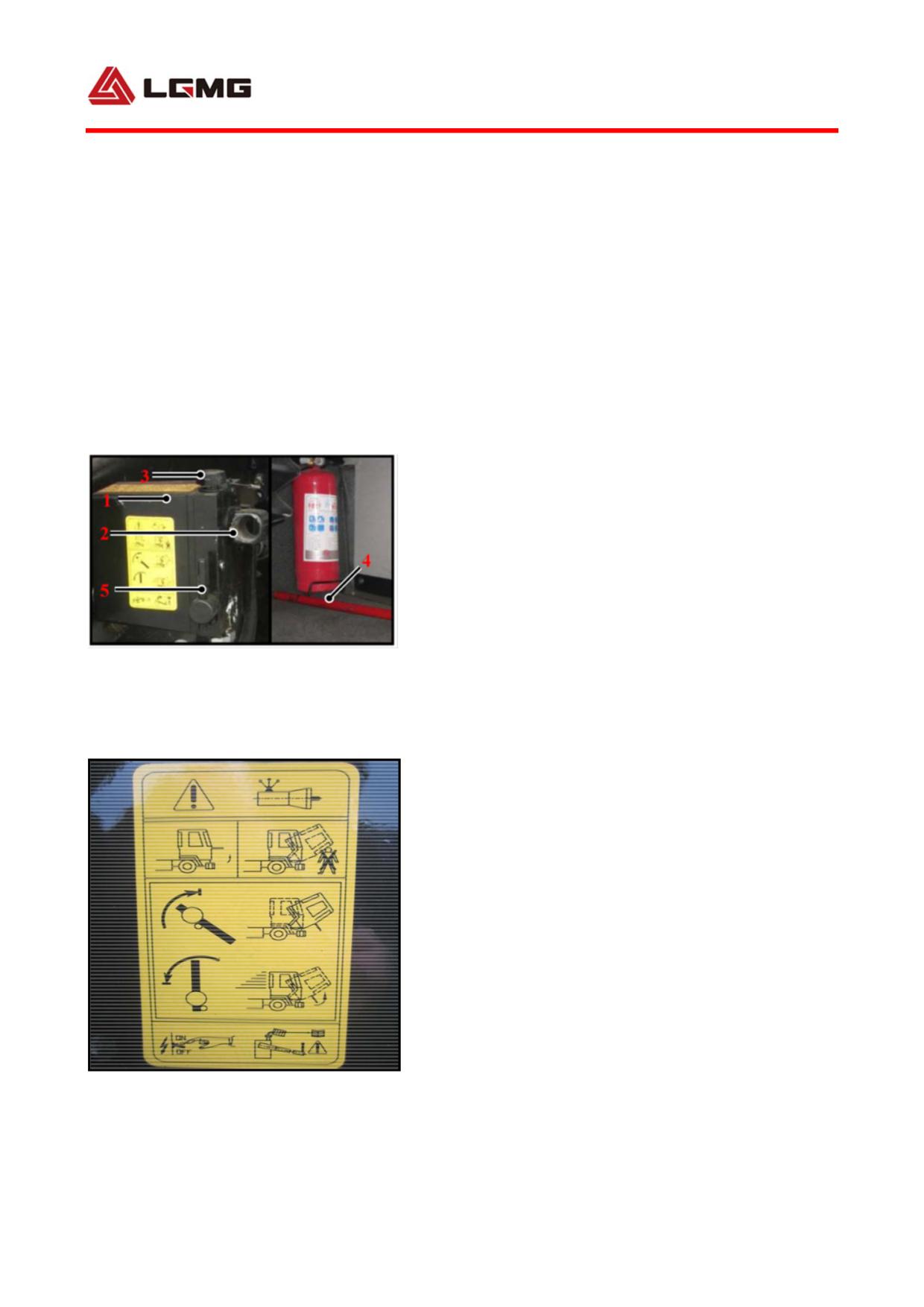
3.5 Cab tilting
3.5.1
Hydraulic
power-assisted
tiltingassembly for cab
As shown in Figure 3-31.
3.5.2 Cab tilting operation (Figure 3-32)
Fig 3-31
1. Hydraulic hand pump
2. Pinch bar jack
3. Oil plug
4. Pinch bar
! WARNING: During the whole process
5. Switchover handle
of tilting, personnel are strictly
prohibited to enter the cab, and
personnel without fixed duties are
strictly prohibited to stay around the
cab.
1) Remove unsecured items in the cab before
tilting.
2) Turn over the cab: pull the manual reversion
Fig 3-32 Cab tilting operations
handle of tiltingpump to the position as shown
35
in the figure, insert the ripping bar and swing
it up and down so as to complete
tiltingoperation; during tiltingoperation,
the position of manual reversion handle shall
not be changed.
3) Turn the cab back: pull the manual reversion
handle of tiltingpump to the position as shown
Fig 3-33 Cab return operations
in the figure, insert the ripping bar and swing
it up and down so as to turn the cab back.
! WARNING: The operation of cab
tilting on a slope is forbidden. Every
time, the cab shall be tilted completely.
In other words, the maintenance and
Fig 3-34
overhaul cannot be done unless the cab
exceeds TDC. When the cab is under
tilting, nobody is allowed to enter the
cab!
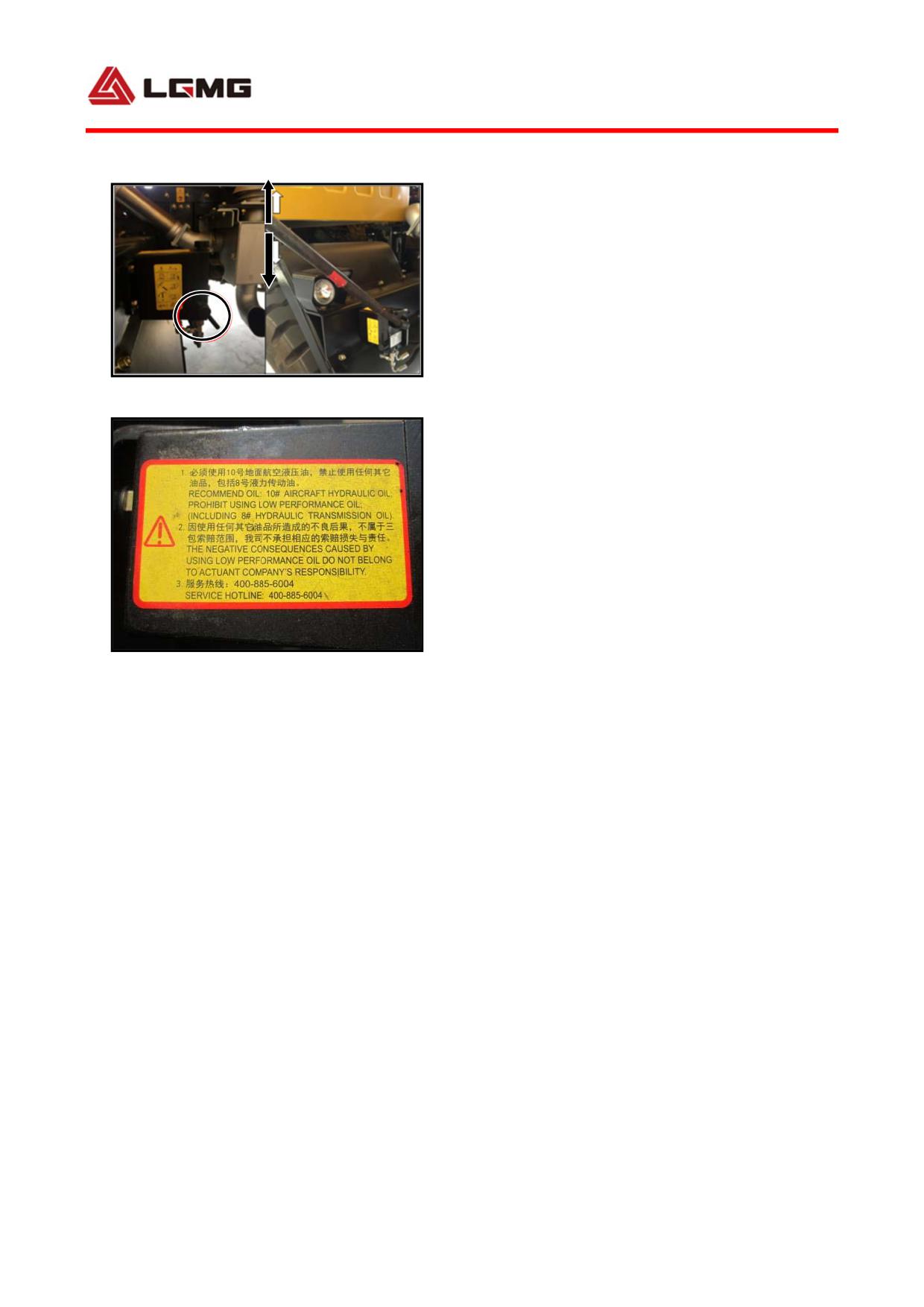
3.5.3 Oiling and bleeding of tilting system
1) Open the oil plug, and top up with the
specified hydraulic oil until it is full.
2) Tilt up the cab gradually while continuing
oiling
3) Lower the cab while letting the excessive
oil overflow.
36
4) Operate the pump to tilt up the cab to return
is back to the original place, check, and top
up.
5) Finally, screw in the oil plug.
!
WARNING: The oiling and bleeding of
tilting system are not allowed unless the
cab is restored.
The low temperature and wear-resistant
hydraulic oil of 0.5 L L-HV32 GB11118.1 shall
be applied. Before filling, always check the
hydraulic oil for cleanness, and add some oil
if acceptable.
3.5.4 Check tilting system function
1) Tilt the cab forward to TDC, and check if
the cab can fall normally after it exceeds TDC.
If the system works normally, the cab will fall
down gradually under resistance without any
obvious impact.
2) After tilted up for about 30º, the cab shall
be held at this position for 20 min without any
settlement.
3.6 Preparation before driving
!
WARNING: Keep a good vehicle condition. Do
not drive in case of any
37
fault!
3.6.1 Preparation
The preparations before driving mainly include:
routine inspection before every driving,
engine start and flameout.
1) Turn on the main power switch (as shown in
Fig. 3-35) to power on the truck.
Fig 3-35
2) Check the working condition of electrical
system. When the key switch is turned on (i.e.
key switch is set to ON), the instrument panels
indicate normally.
3) Check oil/coolant condition of the truck.
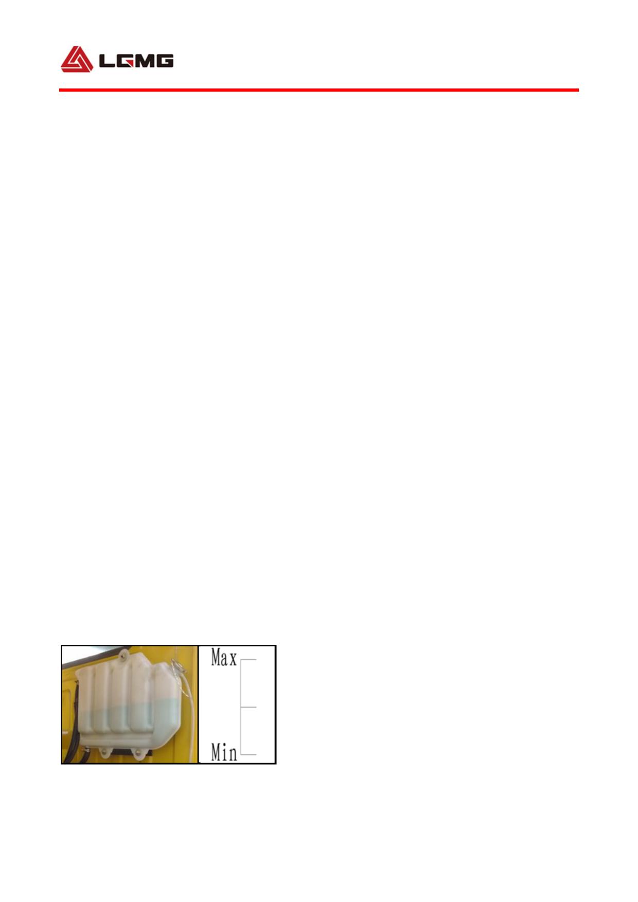
a. Check hydraulic oil: park the truck on the
flat road, lift the container continuously for
Fig 3-36 Oil scale
5 times, and then keep it still for 15min. At
this moment, the standard level of hydraulic
oil shall be between 1/4 of the level meter and
MAX. If the oil level is higher than MAX, drain
oil; if it is lower than 1/4 of the level meter,
Fig 3-37 Glass water scale
refill it to the standard level.
b. Check windshield washer fluid: the
windshield washer fluid visually observed
shall be between 1/4 and 3/4 below the clamp.
If it is lower than 1/4, refill it.
! Note: Refill special windshield
Fig 3-38 Fuel oil level inspection
38
washer fluid instead of ordinary water or
other washing liquid.
c. Check fuel: Open the filler cap, insert the
dip stick until the fuel tank bottom and make
it lean against the upper edge of filler to the
extent that the immersed end of dip stick is
vertical to the tank bottom. At this moment,
the oil trace length shall be between 40mm and
50mm. If it is higher than 50mm, drain the fuel;
if it is lower than 40mm, refill the fuel and
then tighten the cap with the arrow upwards.
d. Check coolant: Start the engine, turn on the
heater to operate for about 2 minutes. At this
moment, the water temperature of the engine
shall be 50 ± 5 ℃, and the coolant level
shall be between MAX and MIN. If it is low,
refill coolant.
When the engine is at low temperature, add the
coolant in two steps:
Step 1: Relieve the high pressure through the
relief valve gradually;
Step 2: Open the cover of relief valve, and add
coolant when the engine runs at idle speed.
! WARNING: Never add coolant when the
engine is still at high temperature!
Fig 3-39 Coolant scale line
39
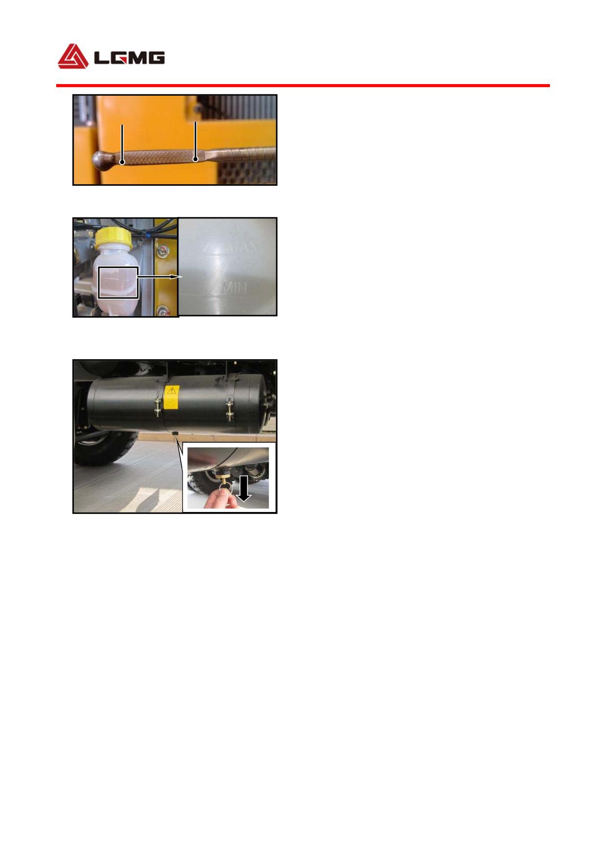
e. Check engine oil: Measure the engine oil
MIN
MAX
level before startup. If it has been started,
do not measure the engine oil level until 15
minutes after stalling.
Fig 3-40 Oil dipstick scale
Pull out the dip stick to clean it with cloth,
and then insert it back into original position.
Pull it out to check the oil trace again. The
upper end of the oil trace shall be between MAX
and MIN. If it is higher than MAX, drain oil.
Fig 3-41 Liquid storage tank and scale line
If it is lower than MIN, refill it to standard
of brake fluid
level.
f. Check brake fluid: Check the brake fluid
under the condition that air has been exhausted
from the clutch system. Refill the brake fluid
until the level is between MAX and MIN. If it
is lower than MIN, refill it to standard level.
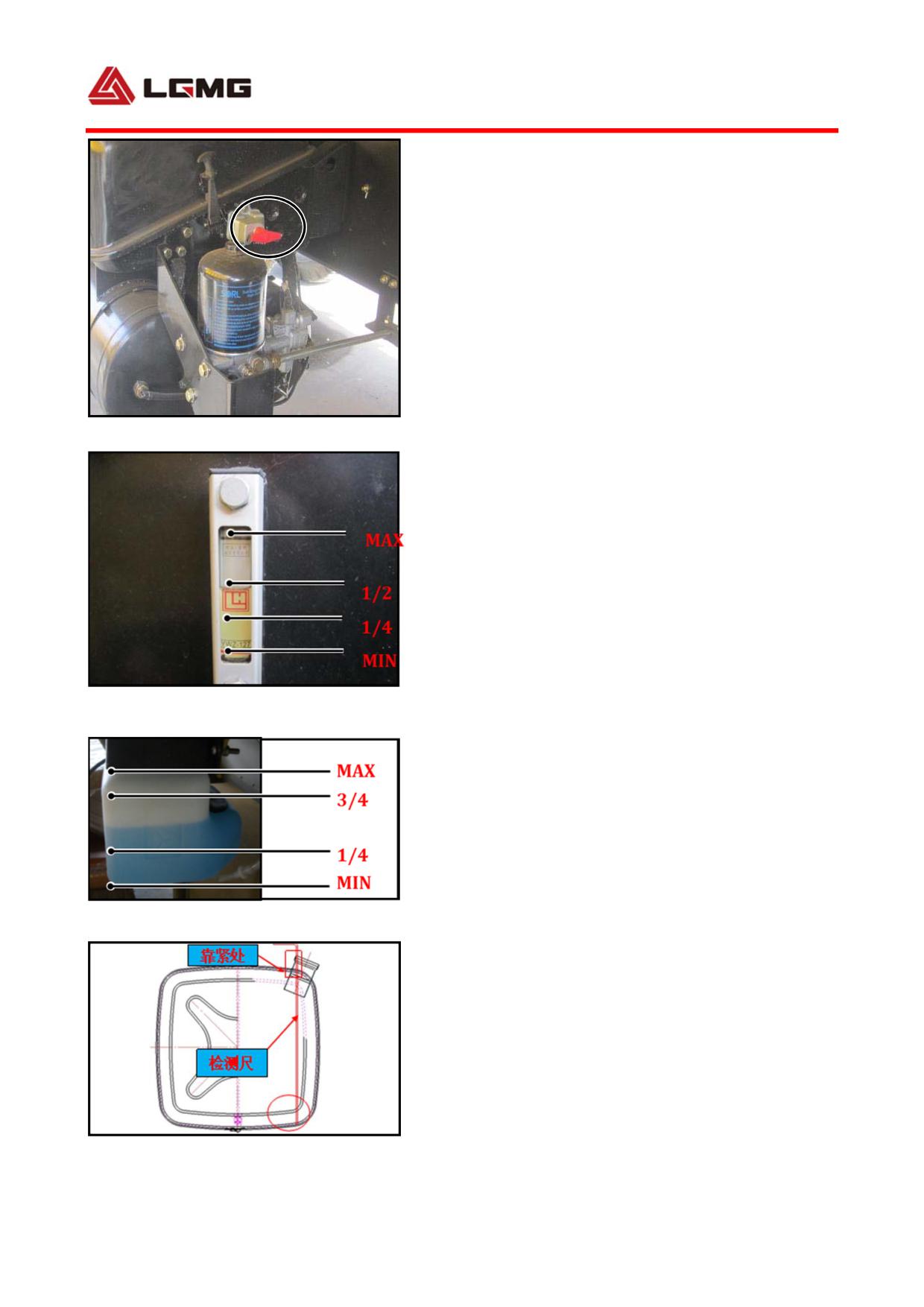
4) Check if there is water inside the air
Fig 3-42
reservoir of exhaust system, and drain if any.
Park the vehicle, pull down or push up the drain
valve to drain off the water condensed in the
air reservoir. If any oil-water mixture is
found, air dryer is ineffective and the
desiccant of air dryer shall be replaced
immediately.
5) Check the tire pressure. If the pressure is
inappropriate, use a specialized inflation
pump to inflate the tire.
40
6) Check the lubricant, coolant and air duct
for leakage.
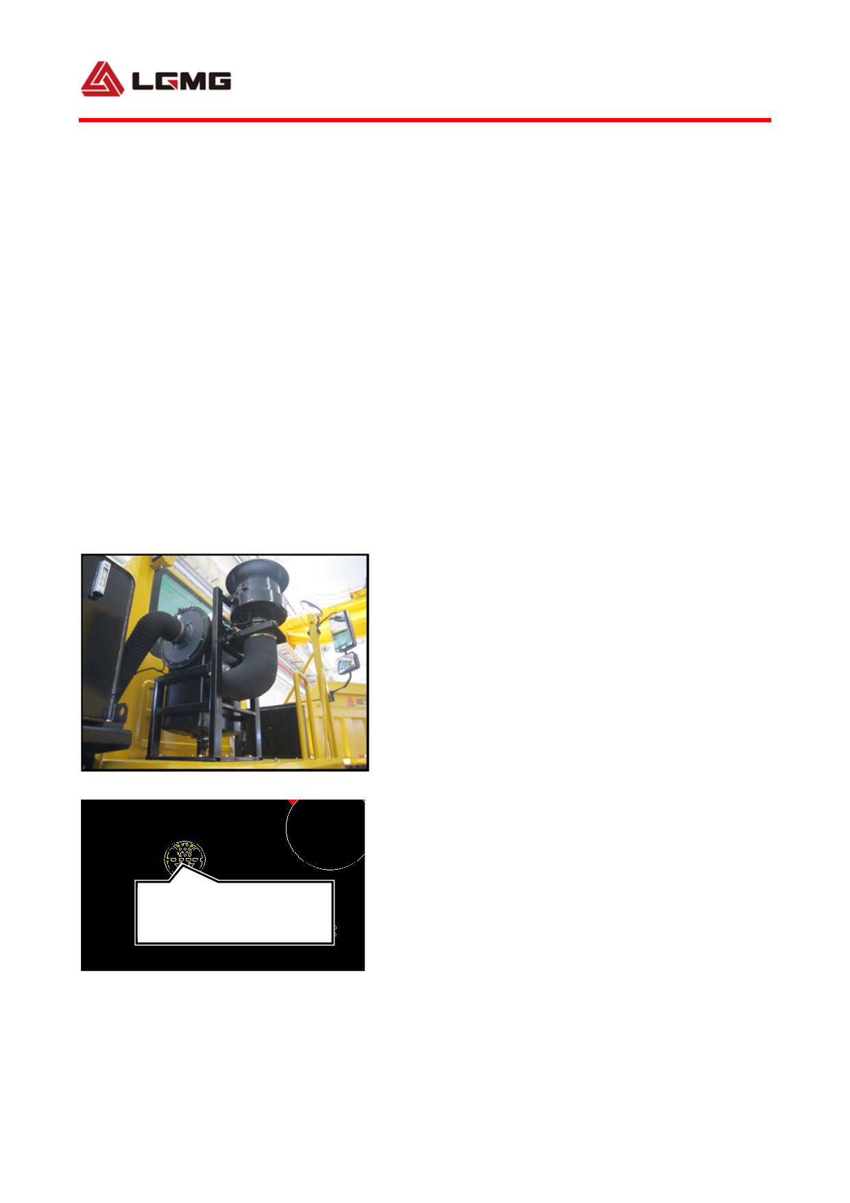
7) Check engine air intake system.
a. Check the primary filter inlet for blockage
by foreign matters to avoid too much negative
pressure present in the air intake system; for
this purpose, insert a thin rod through the
primary filter inlet to move the impeller,
checking if the impeller rotates smoothly.
Otherwise, check or replace the primary filter
to prolong the maintenance interval of air
intake system.
b. Check the air filter outlet to the
supercharger inlet pipeline for damage, and
repair or renew it in time when necessary.
Otherwise, serious early wear will occur to the
engine.
c. Check the air filter blockage alarm
indicator for normal alarming. If the air
Fig 3-43
filter is blocked, this alarm indicator shall
be on. At this time, always check the metal and
paper filter element for blockage, and service
Air filter blockage alarm
or replace it in time.
indicator lamp
10) Before the start-up, check whether there
is any personnel or obstructions in the
vicinity of vehicle.
41
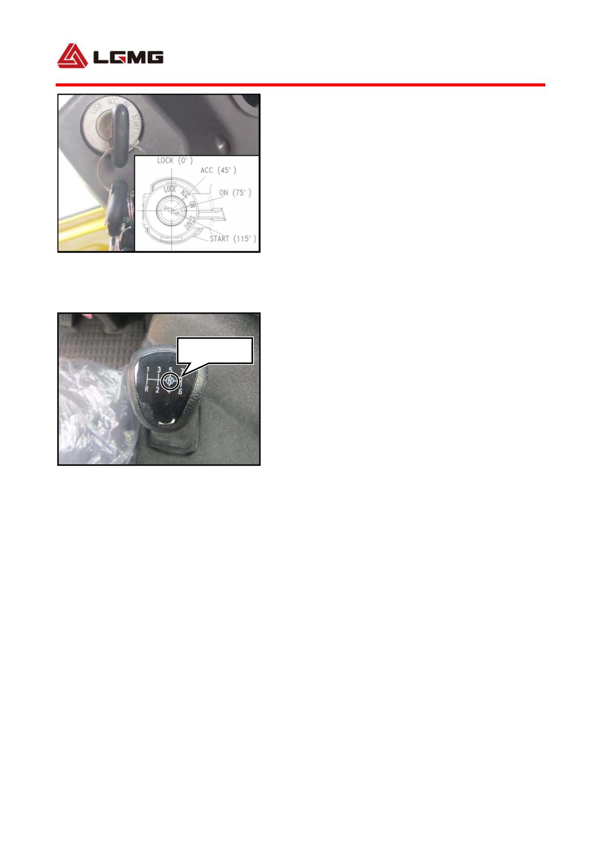
3.6.2 Engine start
1) Turn on the main power switch and turn the
key switch to ON position, getting ready to
start the engine.
! CAUTION: When the vehicle is
running, do not turn off the key switch.
Fig 3-45
In other words, the key switch shall be
set and held at ON position (driving
Neutral
position).
2) Start-up
Release the hand brake, and set the gearshift
lever to NEUTRAL position. Turn the key switch
to START to start the engine.
Fig 3-46 7DS200
! CAUTION: If the engine cannot get
started successfully for the first time,
set the key switch to ACC, and start the
engine again. The time for each starting
shall be no more than 15 s, and the
42
interval between two successive
start-ups shall be no less than 60 s.
However, if it is not possible to start
up for three successive times, stop it
until any fault has been identified and
cleared. After the engine has been
started, make it idle for a few minutes,
and then increase the speed to
1,000-1,200r/min, and apply partial load.
Full-load operation is allowed only when
the outlet temperature is higher than
60℃, and the engine oil temperature is
higher than 50 ℃. The load and speed
shall be increased gradually to avoid
sudden load adding or shedding.
3) Oil pressure after start-up
After the engine gets started, observe the
pressure value indicated on the oil gauge.
Meanwhile, the oil pressure indicator lamp
shall be off.
! CAUTION: Never run a cold engine at
a high temperature! If the oil gauge
gives no reading after the engine is
43
started, immediately shut down the
engine for overhaul.
4) Operation of supercharger
The supercharger is installed at the rear upper
end of engine, consisting of turbine assembly
and pump impeller assembly. The exhaust gas
discharged by the engine will drive the turbine
and the pump impeller on the same shaft to
rotate at a high speed, discharging the
compressed air into the engine air intake pipe
to increase the intake pressure and increasing
the engine power.
The rotor in the supercharger normally runs at
a very high speed (about 70,000-100,000 rpm).
The rotor bearing is forced lubricated with
hydraulic oil provided by engine main oil duct.
The oil supply will be cut off as long as the
engine shuts down.
Precautions during operation:
a. To start the engine, run it at idle speed
for 2-3 min without depressing the accelerator
forcibly in this process, and do not apply load
until the oil pressure and temperature are both
normal (especially for start-up in cold days);
otherwise, the damage caused by early wear can
is likely to occur to bearing and sealing ring
44
of supercharger.
b. To shut down the engine, always run it at
idle speed for 2-3 min, and shut it down after
the supercharger slows down. Pay special
attention not to depressing the accelerator
forcibly before the engine stops. If the
supercharger will decelerates substantially
due to the sudden rise of engine speed when the
engine shuts down all in a sudden, the oil pump
will stop oil supply immediately; however, the
rotor of supercharger will keep rotating at a
high speed due to its inertia, thus resulting
in quick burnout of rotor shaft, bearing and
sealing ring because of oil shortage.
c. Before starting the engine which has been
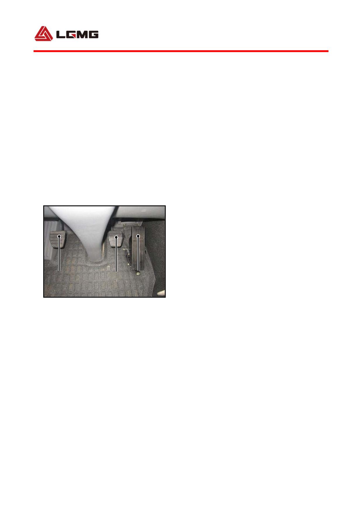
1
2
3
withdrawn out of service for a long time,
Fig 3-47
always pre-lubricate the supercharger by
1. Clutch pedal 2. Brake pedal
removing the supercharger oil inlet pipe and
3. Accelerator pedal
adding appropriate amount of clean lubricant
from the filler port. Otherwise, the initial
start-up will lead to parts early wear due to
oil shortage.
3.6.3 Engine shutdown
When the vehicle runs downhill, press down the
exhaust brake switch or depress the exhaust
brake pedal, and then the engine oil supply
45
will be cut off for exhaust braking.
The engine may be overheated after it runs
overloaded, and in this case, the engine should
be shut down after running at idle speed for
2-3 min.
3.7 Start-up and gearshift
! WARNING:The user is asked to drive
the vehicle according to the
instructions, and the user is conceited
for all the consequences of the illegal
driving.
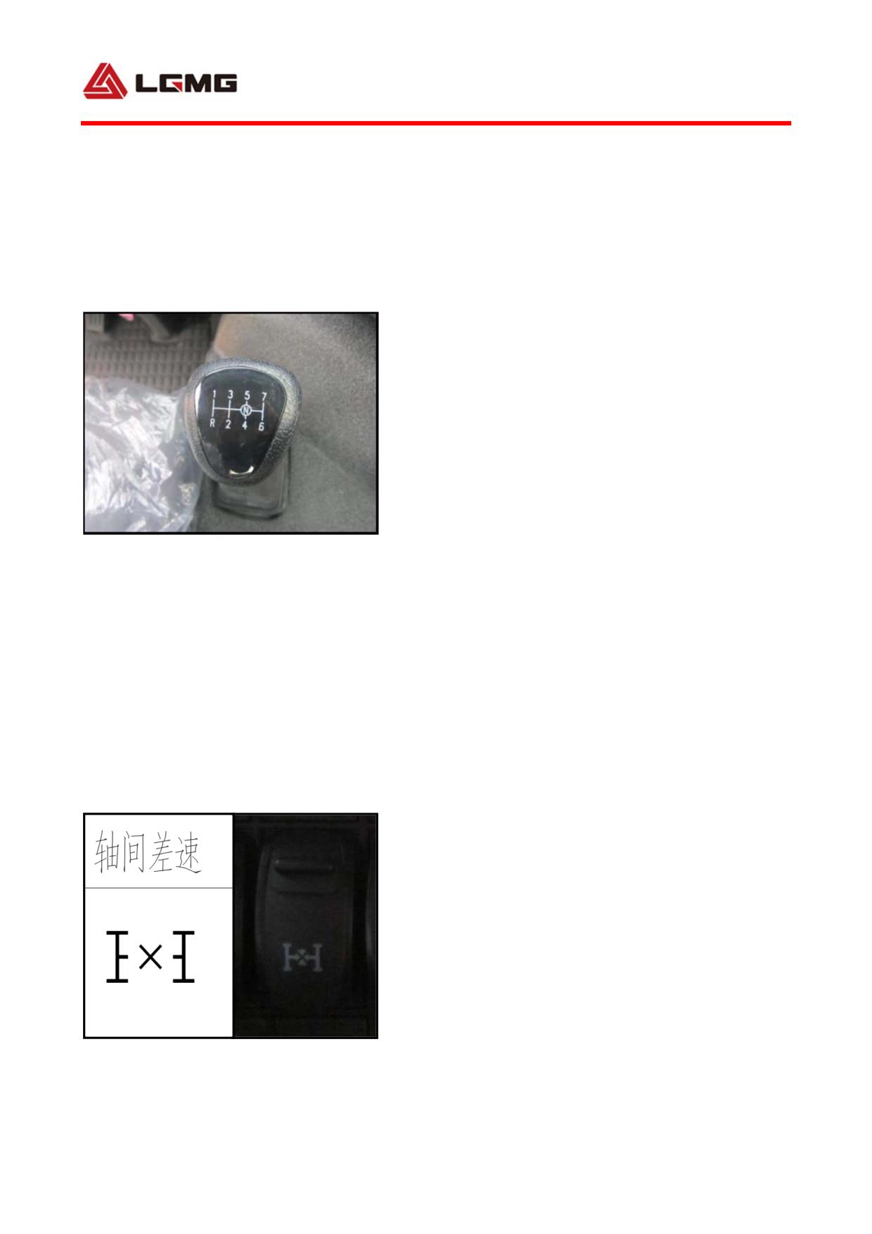
Fig 3-48 Transmission gearshift lever
3.7.1 Start-up
If the engine is started, and the low pressure
indicator is on and the buzzer keeps sounding,
do not release the brake handle to start the
vehicle until the inflation pressure reaches
0.55 MPa (5.5 bar), low pressure alarm
indicator is off and the buzzer stops sounding.
△!WARNING: Always start the MT86 mining dump
truck at gear 1.
3.7.2 Transmission gears and operation
See "4.4 Operation and maintenance of
Fig 3-49 Differential lock button
transmission" for details.
3.7.3 Differential lock
46
The drive axle of MT86 mining dump truck is
equipped with bogie differential lock. When
the wheel slips or gets stuck in the mud, the
bogie differential lock can lock the bogie
differential between the intermediate axle and
the rear axle, thus increasing the vehicle
trafficability.
1) Connection of bogie differential lock: Only
when the vehicle is parked or travels straight
at a low speed (equivalent to walking speed)
can the differential lock be engaged.
Press down the bogie differential rocker
switch. When the bogie differential is engaged,
the bogie differential indicator on the
instrument panel will be on.
! WARNING: When the vehicle is
running, always release the clutch
before the connection of bogie
differential lock!
2) Disengagement of bogie differential lock:
Release the accelerator, depress the clutch,
and pull up the bogie differential rocker
switch. When the bogie differential is
disconnected, the bogie differential
indicator on the instrument panel will be off.
47
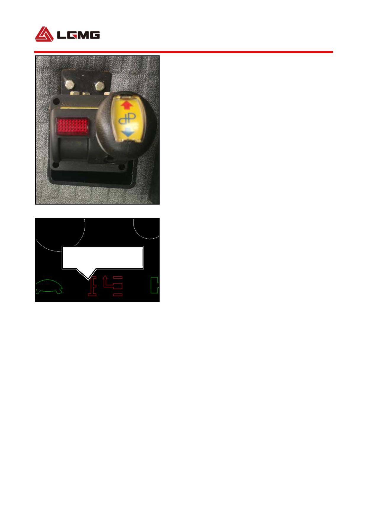
3.7.4 PTO operation
! CAUTION: PTO can be used only on the
engine-out condition! It is not allowed
to use the PTO in the low or reverse gear.
This manual only gives introduction to PTO
engagement and disengagement. For operation
and maintenance of the hydraulic lifting
system, refer to the User Manual of Hydraulic
Fig 3-50 Take power device
Lifting System.
1) Container lifting
Depress the clutch pedal, and push the handle
Parking PTO indicator
in the direction indicated by the red arrow to
lamp
engage the power takeoff. At this moment, the
parking and power takeoff indicators on the
dash board turn on. Continuously push the
Fig 3-51 Parking PTO indicator lamp
handle to lift the container.
△!Note: Depress the accelerator pedal (engine
speed ≤ 1,800r/h), pull up the handle to keep
the container lifted (or stop lifting by
releasing the handle).
2) Container lowering
When the handle is pulled down in the direction
indicated by the blue arrow to the extent that
the handle is in the return position, the
container automatically lowers, and the power
48
takeoff switch automatically opens and
returns.
3.8 Operation at low temperature
environment
3.8.1 Engine cooling system
The long-life antifreeze and anticorrosion
coolant applied by the engine cooling system
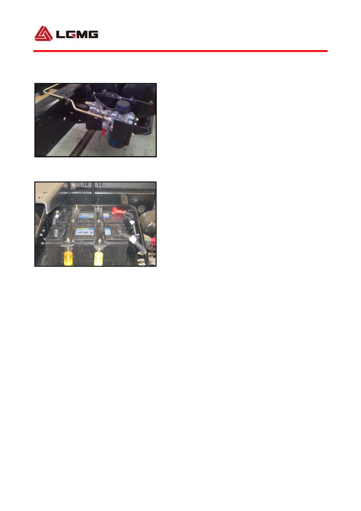
Fig 3-52 Air dryer
can be kept unfrozen above -35℃. If the
vehicle has to work in the environment below
-35℃, the coolant concentration should be
increased appropriately.
! CAUTION: The mixture of antifreezes
of two different brands is not allowed.
Before changing the antifreeze,
Fig 3-53 Batter
thoroughly clean the cooling
system.Selection of coolant at different
freezing points based on local ambient
temperature,The selection principle is
the air temperature is about 10C lower
than the freezing point.
3.8.2 Brake system
Drain off the water condensed in the air
reservoir in case of freezing, and note to
check the air dryer for working
49
condition.Under normal condition, the service
life of desiccant in the air dryer is half a
year. If any oil-water mixture is drained from
air reservoir, air dryer is ineffective and the
desiccant should be replaced immediately.
3.8.3 Battery
The battery applied is maintenance-free. If
the vehicle will not be used for a long time
and the temperature is low, you had better
remove the battery and place it in a warm room.
Check the battery electrode terminal and
conductor connection clamp for looseness and
the battery for normal working condition every
500 km.
! WARNING:
● Before the battery repair, always
keep good ventilation.
● Nobody, other than professional
service personnel, is allowed to repair
and remove the battery without
permission!
● While removing (installing) the
battery, always disconnect (connect) the
negative cable first!
50
3.8.4 Startup system
Start the engine with an auxiliary startup
device under low temperature. Make the
electronic heating flange operate with a relay
so as to start the engine successfully under
-30 C.
3.8.5 Park
In case of cold climate, do not park until
remove the load firstly and then make it run
at idle speed for 2-3 minutes, and the water
temperature and the oil temperature drop.
After parking, do not drain the coolant
containing anti-freezing additive. If the
coolant contains no anti-freezing additive, it
is necessary to open the water drain valve or
water plug on the engine, the oil cooler cover,
the radiator, the water inlet pipe and the like,
to drain the coolant to prevent the engine from
being frozen.
3.9
Wheel replacement and
tire pressure
1) While replacing the wheels, be careful not
to damage the thread of wheel rim bolt.
51
2) The fitting surface of brake drum and wheel
rim shall be free from paint, grease or other
contaminants.
3) The seal face of wheel nuts shall be kept
clean without contaminants or oil stain.
4) Before installing the wheels, wipe up the
outer circle matching with the wheel locating
hole and final drive housing, and apply a few
grease.
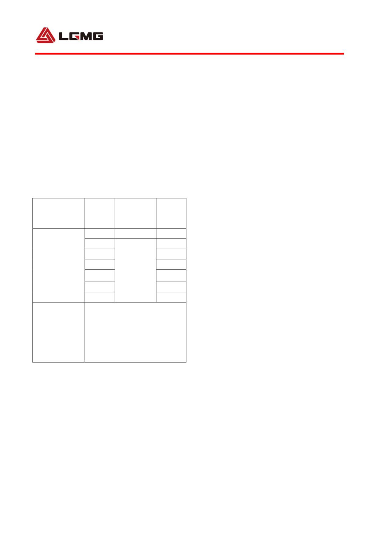
Air
Speed
Load
5) Apply a few grease, engine oil or other
Level
pressure
km/h
kg
kpa
anti-seize to the threads of wheel bolts and
10
1200
11500
nuts.
14.00-25
15
7300
20
7150
Tire of
6) All wheel nuts have right-handed threads.
construction
25
7000
850
To install the wheels, pre-tighten the nuts
machinery
30
6900
36 level
35
6750
diagonally with the wheels suspended, lower
40
6700
down the wheels, and tighten the nuts to the
The above data are for
reference only. The specific air
specified torque*.
pressure adjustment shall be
Remarks
subject
to
Operation
* Specified torque of wheel nuts: Use a 36 mm
Instructions provided by the
hexagon socket to tighten MT86 wheel rim bolt
manufacturer.
to a torque of 700 - 800 Nm.
7) Each time when a tire is refitted, always
tighten the wheel nuts again after the vehicle
travels 50 km. Thereafter, check and tighten
the wheel nuts again every 1,000 km.
8) Please inflate the tire according to the
“Comparison table of speed, load and air
pressure” (see left table).
52
3.10 Running-in of new vehicle
The running-in mileage is 1,500-2,500 km as
specified.
Before running-in, do routine inspection to
ensure that the vehicle is kept in normal
working condition.
Precautions for running-in:
1) Do not speed up immediately after the engine
gets started. Only when the coolant
temperature reaches normal range can the
engine speed be increased.
2) During running-in, the vehicle shall travel
along a relatively even road with good
condition.
3) Do gearshift in time and engage the clutch
smoothly for the avoidance of sudden
acceleration and emergency brake.
4) Before travelling uphill, engage a low gear
in time in case that engine runs at a too low
speed.
5) A new vehicle cannot travel at full speed
with full load. Always monitor the instruments,
indicator lamps and alarm indicators!
6) Check and control the engine oil pressure
and coolant temperature. Monitor the
temperature of transmission, front/rear axles,
53
wheel hub and brake drum. In case of
overheating, find out the cause, and adjust and
repair in time.
7) The vehicle must experience a run-in of
1,500km. it might be put into use after the
brake interval is readjusted and the fasteners
(except gelatinizes bolts) are rechecked.
At the completion of running-in, check and
service the vehicle according to “first-class
maintenance” in maintenance provisions
herein.
54
Chapter IV Operation and Maintenance of Main
Assemblies
55
56
4.1 Operation and maintenance of
engine
4.1.1 Operation and maintenance of engine
See Operation and Maintenance Manual of WD12
Series Diesel Engine for details
4.1.2 Change of engine oil,filter,prefilter
During operation of MT86H, it is necessary to
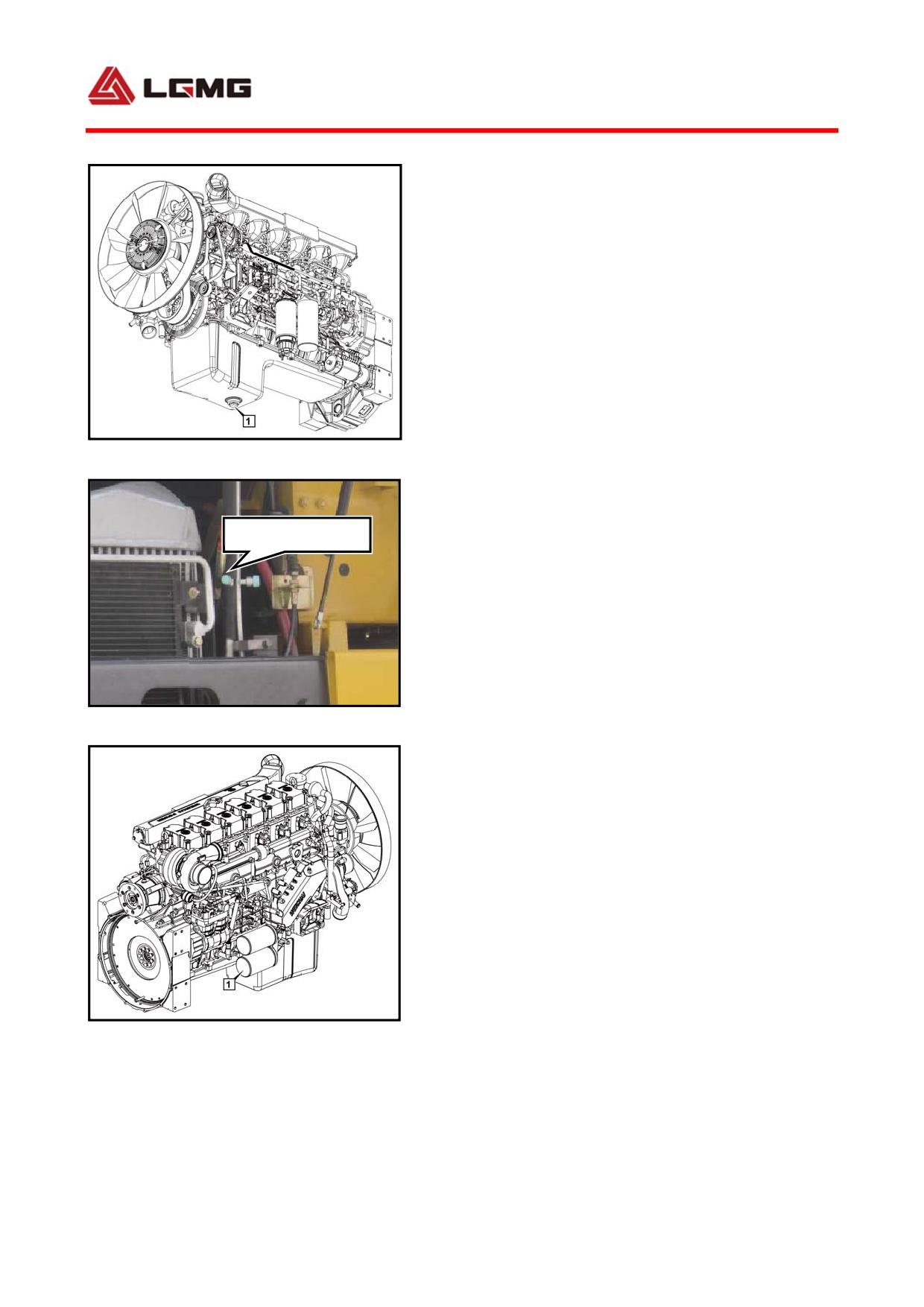
Fig 4-1
1. Drain plug
periodically replace engine oil, filter and
pre-filter as appropriate to keep the engine
Oil dipstick
operating properly.
1) Change of engine oil
Interval: Within the limited period (mileage)
of the mandatory maintenance, the engine oil
should be changed in strict accordance with the
Fig 4-2 Oil dipstick
period specified in “Mandatory Maintenance of
5.2 MT86H mining dump truck”; while over the
limited period (mileage) of the mandatory
maintenance, refer to the interval specified
in Operation and Maintenance Manual of WD12
Series Diesel Engine for replacement.
a) Pull the drain plug open to drain the oil
off.
Fig 4-3
1. Oil filter
Inspect whether the oil has a normal color and
any foreign materials while draining, and
57
eliminate timely the fault potential if any.
b) After the oil has been drained off, remove
the foreign materials from the drain plug that
then should be screwed on.
c) Replace with a new oil filter element, and
fill the engine with new oil to the upper limit
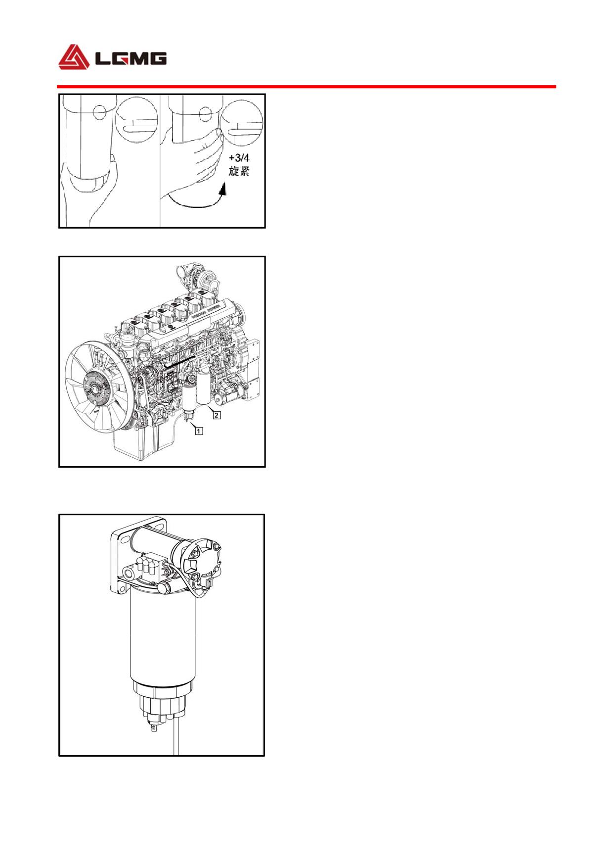
Fig 4-4 Change the oil filter
of the dipstick. To avoid starting an
unlubricated engine, when the high pressure
oil pump is set at OFF position, turn the key
switch to start position (4th gear), let the
engine idle for a while, and after the engine
is completed with pre-lubrication, start and
run it at a low speed, and check if the oil
filter is leaking oil.
2) Oil filler
Fig 4-5 Fuel filter
Replacement interval: In the limited period
1. Fuel coarse filter 2. Fuel fine filter
(mileage) of the mandatory maintenance, the
oil filter should be replaced in strict
accordance with the period specified in
“Mandatory Maintenance of 5.2 MT86H mining
dump truck”; while over the limited period
(mileage) of the mandatory maintenance, the
replacement is required every 5000 Km (200h).
Each time the engine oil is changed, the oil
filter should be replaced as well.
Replacement method: Remove the filter with a
special filter wrench before replacement. To
Fig 4-6 Fuel filler(protector)
58
fit a new filter, clean up the fitting surface
first, fill the filter full with clean media
to be filtered, lubricate the rubber seal ring
with little clean media to be filtered, then
install the filter by hand and screw it for 3/4
circle after the sealing surface bonds with
fitting surface. Start the engine to check if
the sealing surface is leaking oil, and if any,
tighten the filter again until there is no oil
leaking any more.
3) Fuel filter
The replacement interval and replacement
method are the same with “2) Oil filter”.
4) Fuel primary filter
The replacement interval and replacement
method are the same with “2) Oil filter”.
4.1.3
Routine
maintenance
and
considerations
1) Check the coolant level, oil level and fuel
level.
2) Check if the grease is sufficient at
required position.
3) Check for oil, water and gas leakage.
4) Check connection of external connection
pieces and accessories.
5) Check if the fan belt is too tight or too
59
loose.
6) Check the oil pressure and water temperature
of the diesel engine.
7) Check if the exhaust temperature, color,
sound and vibration are normal, and the speed
is stable.
Refer to "Periodic Inspection and Technical
Maintenance of Diesel Engine" section of
Operation and Maintenance Instruction of WD12
Engine for details.
4.1.4 Maintenance
MT86 engine shall be inspected and maintained
at interval specified in “5.1 Interval
Mileage of Routine Inspection and
Maintenance”. Refer to "Periodic Inspection
and Technical Maintenance of Diesel Engine"
section of Operation and Maintenance
Instruction of WD12 Engine for details.
4.2 Operation and maintenance of intake
system
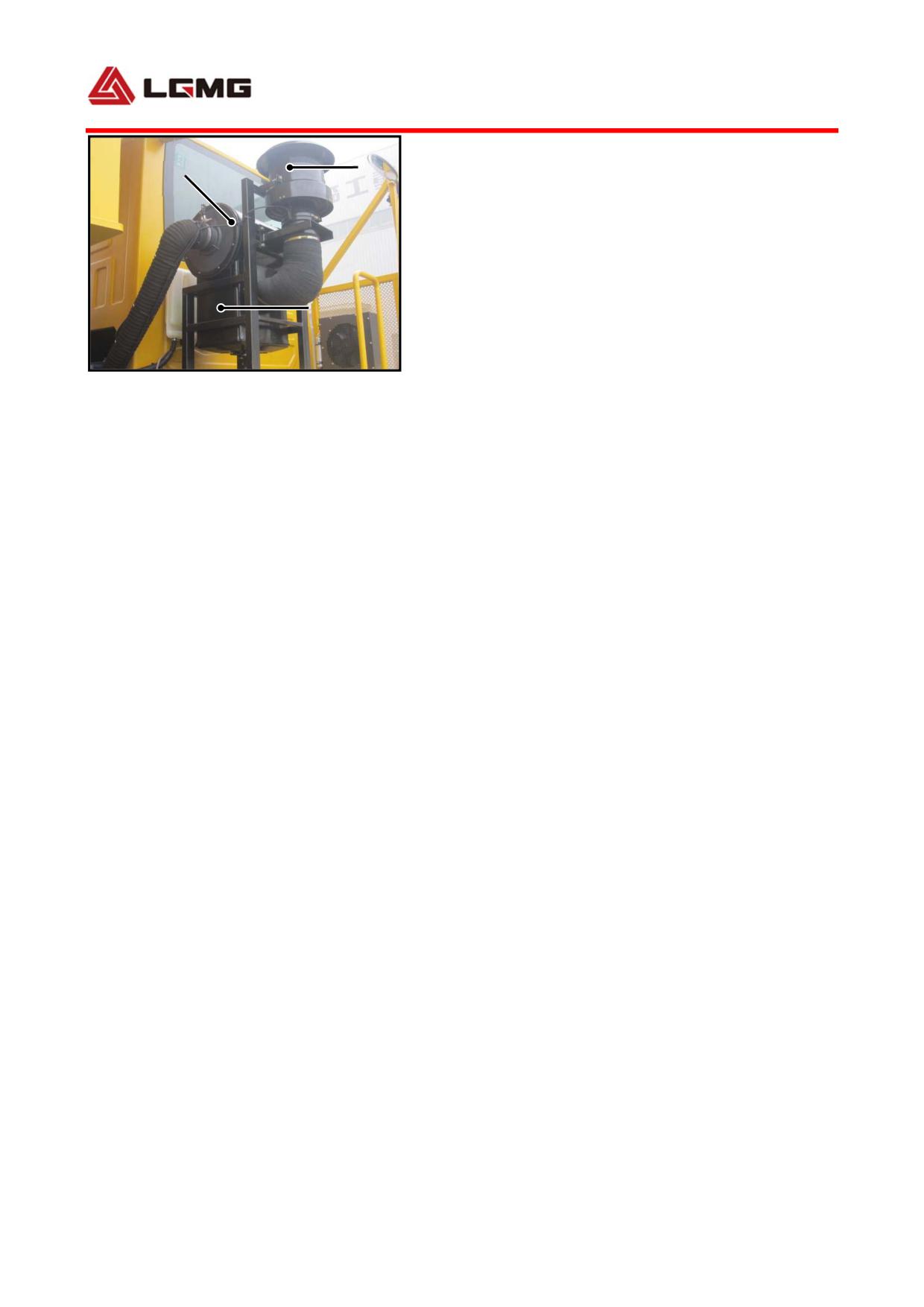
The working component of the intake system is
the three-stage desert filter, which consists
of the cyclonic prefilter, coarse filter and
fine filter.
60
1
3
4.2.1 Cyclonic prefilter
The cyclonic prefilter is maintenance-free and
is removed for inspection only when there is
2
abnormal noise, and if necessary, the rotator
should be replaced.
Fig 4-7
4.2.2 Coarse filter
1.Cyclonic prefilter
2. Coarse filter
3.Fine filter
1) Check the dedusting valve frequently, and
clean the coarse filter in the case of
clogging;
2) Remove and clean the coarse filter carefully
every 2-3 months;
Maintenance steps:
① Remove the fixed points around the bottom
cover; ② Remove the bottom cover; ③ Clean
the dust in the bottom cover and dust
collecting duct; ④ Install the bottom cover
to confirm the sealing performance.
! CAUTION: The damaged or ageing seal
ring should be immediately replaced with
a new one; the dedusting valve should be
replaced with a new one immediately in
the cae of loss, ageing or damage.
61
4.2.3 Fine filter
The fine filter is composed of the main filter
element and the safety filter element.
The main filter should be maintained when the
indicator alarms or every 200-250 working
hours.
The safety filter element is only used as
second protection and may not be cleaned.
Maintenance method:
① Unscrew the fixing nut, and carefully
remove the main filter; ② Blow off the dust
on the main filter element with clean air below
0.5MPa diagonally from the inside to outside;
③ Check the filter element inside and outside
and the seal ring for any damage; ④ Clean the
air filter housing inside, and check the inner
filter element for damage; ⑤ Place the outer
filter element gently back into the filter
housing, and check whether the outer filter
ring comes into contact with the housing; ⑥
Determine that the outer filter element has
been installed in place, and tighten the nut
and insert the spring pin into the pin hole.
The main filter element and safety filter
element should be replaced in the following
conditions:
62
① The main filter has been damaged; ② After
the indicator is cleaned and installed, it
still alarms:
③ The main filter element has been cleaned for
5 times.
! CAUTION: The safety filter element
cannot be cleaned, and should be replaced
together with the outer filter element.
4.3 Operation and maintenance of clutch
control system
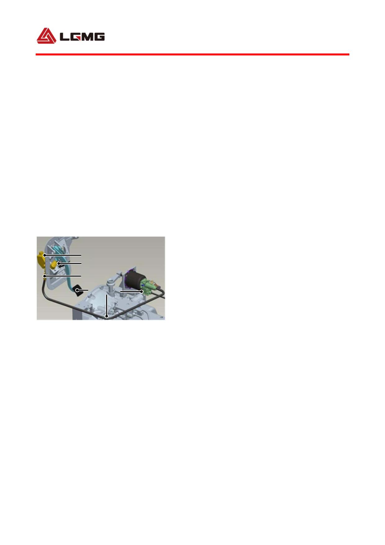
4.3.1 Working principle
The clutch control system is hydraulically
1
controlled and pneumatically boosted. With the
2
3
clutch pedal stepped on, the drive cylinder
4
5
6
push rod pushes the piston to move forward, so
that the brake fluid, which flows along the
fluid pipe into the hydraulic control cavity
Fig 4-8
1. Clutch oil reservoir 2. Clutch master cylinder push
of clutch booster cylinder, provides working
rod 3. Clutch drive cylinder 4. Clutch pedal assembly 5.
pressure on the piston, and besides, serves as
Clutch oil pipe 6. Clutch booster cylinder
control pressure to control the air pressure
in the booster cylinder chamber. When
compressed air gets into the booster cylinder,
the generated force will push the piston to
move the booster cylinder push rod, and drive
the release rocker arm to rotate, such that the
release fork makes the release bearing move
63
backward, finally to release the clutch
successfully.
The clutch drive cylinder, clutch fluid
reservoir and clutch pedal assembly etc. are
arranged to the front wall of the cab, with the
drive cylinder connected to the clutch booster
cylinder on the chassis through high pressure
hose, and one bracket shared by the clutch
operating part and the brake operating part.
The fluid reservoir is installed directly on
the clutch drive cylinder, and the brake fluid
can be added outside the cab as long as the
radiator cover is uncovered.
4.3.2 Working parameters
1) Working media: compressed air and brake
fluid.
2) Max. working pressure: 4 MPa for the brake
fluid and 0.85 MPa for the compressed air.
3) Working temperature: -40°C~+80°C.
4) Brake fluid: as per DOT3 and DOT4 standards.
5) Pedal travel: a maximum travel ≤ 175 mm.
6) Pedal operating effort: ≤190 N (when
pneumatically boosted).
4.3.3 Installation and adjustment of clutch
and clutch control system
1) Installation of clutch: Put the driven disc
64
assembly on the spline shaft (with a tool used
for positioning the clutch driven disc to be
installed), with the fly wheel central hole
aligned. Assemble any two holes of the clutch
pressure plate assembly to the two studs on the
fly wheel, then install the other 10 hexagon
bolts respectively, and tighten them
diagonally.
2) Pull-type clutch connection: After a
pull-type clutch is installed with the
procedures above, take the four clamp springs
off the pressure plate assembly, close the
flexible lock ring on the clutch pressure plate
assembly, and install the release bearing and
release fork properly. Since the transmission
has been installed to the engine fly wheel,
apply a backward force to the release fork at
the booster cylinder mounting port (pull
backward through a flexible rope attached to
the upper end of the release fork), and as long
as a sound of clap is heard, the clutch cover
assembly and release bearing are assembled in
place (i.e. the flexible lock ring clamped on
the release bearing), after which, the booster
cylinder should be installed.
3) Inspection and adjustment of clearance
between the drive cylinder push rod and piston:
65
While adjusting, push the pedal gently by hand
until you feel the drive cylinder push rod
against the piston, adjust the height of stop
bolt to ensure a clearance between the push rod
and piston of 0.5 mm~1 mm, and then tighten the
nut. The clearance hereof should be no more
than 1 mm, or the effective stroke of the drive
cylinder may shorten.
4) Bleeding of hydraulic system: If there is
air in the clutch hydraulic system, the
effective stroke of the booster cylinder push
rod will shorten, resulting in an incomplete
clutch release, as well as gear engagement
difficulty. To add new brake fluid, release the
booster cylinder bleed valve, fill the fluid
reservoir with brake fluid of specified grade,
replenish brake fluid while stepping on the
clutch pedal until it spills out of the bleed
valve, and tighten the bleed valve. Then
depress the clutch pedal for several times, and
hold it, release the booster cylinder bleed
valve until no air comes out, then tighten the
bleed valve. Repeat the steps above for 2~3
times, so that the air in the hydraulic system
can be discharged thoroughly.
66
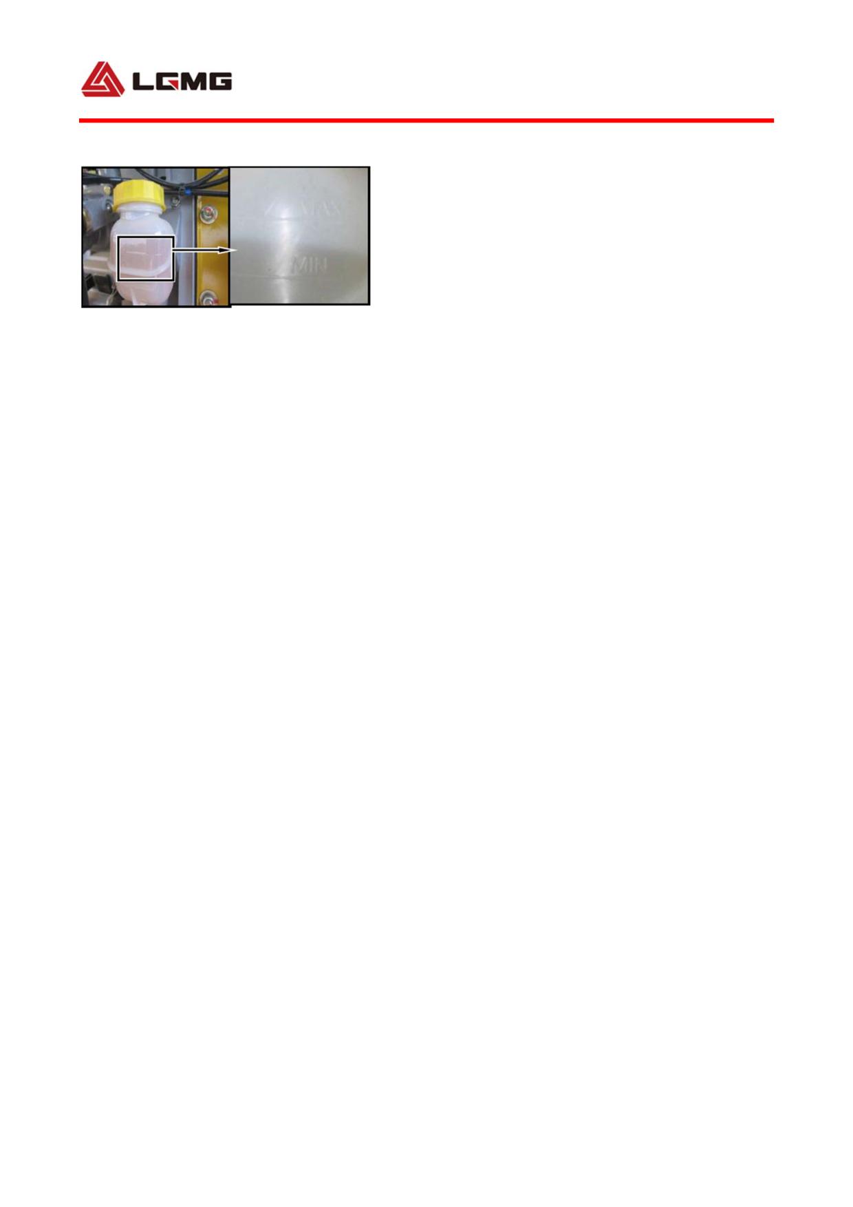
4.3.4 Precautions
1) Remember to release the pedal after the
bleed valve is tightened during air discharge
in order to avoid air suction, and allow the
Fig 4-9 Brake fluid
pedal to rise up to the maximum height, so that
the brake fluid in the fluid reservoir is added
into the drive cylinder hydraulic cavity.
2) The working medium for hydraulic system must
be brake fluid of DOT3 and DOT4.
3) To change the brake fluid, the residue in
the hydraulic system has to be cleaned. Then
uniformly change the brake fluid of specified
grand and same lot. The brake fluids of
different grades and lots shall not be mixed.
4) As the brake fluid is corrosive, while
discharging air, try not to spatter any brake
fluid onto human body and vehicle finish.
5) Periodically inspect the brake fluid
reservoir level of clutch master cylinder. If
the brake fluid level is below Min mark, the
brake fluid of a specified type should be added,
until its level is between the scale marks of
Min and Max.
67
4.3.5Common faults and troubleshooting
Faults
Causes
Solutions
The
transmission
is
misaligned at re-assembly;
Align the driven disc assembly carefully, and
Clutch
return
The hub is mounted on the
align the clutch with an analog spindle;
difficulty causes
input shaft, and the driven
Do not push the transmission forcibly, but rotate
shift difficulty
disc
assembly
rotates
the flywheel or the input shaft to align it with
through the hub in the
splines of the hub
direction of the input shaft
1.
The weight of the
transmission is completely
It is out of work
Do not load the input shaft or the transmission
loaded on the hub and is
and loud noise
on the driven disc, but support the transmission
damaged due to distortion
occurs after a
with a manual or electric lift for assembling;
after short-term operation;
few
hundred
Do not operate it like a racing automobile.
2. Operate the clutch like a
kilometers
Educate the driver.
racing automobile or tow a
heavy trailer
The clutch slips,
but the control
Check the oil seal of the engine and
system operates
Oil
leaks
from
the
transmission carefully. If there is oil in the clutch
properly,
and
transmission or the engine
housing, replace the oil seal.
the regulation is
correct
The clutch is
Only a certain amount of suitable grease is
shaking at the
There are too much
permitted
initial stage of
copper-based grease on
Warning: copper-based grease dilutes under
the transmitting
splines of the input shaft
high temperature and radiates outwards under
torque
centrifugal force
Improper operation. Shift
It is out of work
5th gear to 2nd gear at 85
Educate the driver
miles
Shift is difficult
The truck starts at a bumpy
or is unavailable
place or starts and tows with
Do not engage 1st gear, but high-speed gear
after the clutch
an inappropriate gear, or the
such as 3rd gear or 4th gear, when the truck
has
been
clutch cover assembly is not
starts at a bumpy place or tows.
operated for a
suitable for the truck
period of time
68
Fault
Causes
Solutions
The cap assembly drops
Do not use the cover assembly that has ever
Shift is difficult
during assembly so that the
dropped;
or is unavailable
return spring is twisted;
Check the return spring carefully before
after the clutch
The spring (with scratch on
assembling;
has
been
the drive disc) is damaged by
Do not try to insert the drive disc to stop the
changed
tool during assembling
engine with a tool while the engine is running
Shift is difficult
The clutch cover is not
or is unavailable
accurately positioned;
Check the positioning before assembling;
after the clutch
Bolt tightening sequence is
Tighten bolts in proper sequence (diagonally)
is renewed
not proper
The transmission input shaft
Accurately guide the clutch into the
Pedal jitters at
interferes
with
the
transmission input shaft to avoid any
disengaging
disengaging lever during
interference during assembling
assembling
Check all relevant connections thoroughly
It is difficult to
The pre-load of the release
during the clutch assembling; ensure that the
depress
the
bearing is too small or it is
clutch cable operates smoothly throughout
pedal and the
not preloaded;
operation of the clutch; check the self-regulator;
stiffness
The preloaded spring is not
always refer to the installation manual of the
increases with
installed properly or the
manufacturer for proper regulation; keep the
time.
self-regulator has failed
preload between minimum 50N and maximum
80N
The
noise
associated with
Check the cable, related connections and
the
engine
The clutch regulation is
self-regulator systematically, and always refer to
occurs when the
improper
or
the
the installation manual of the manufactuter for
pedal
is
self-regulator has failed
proper regulation
depressed
to
the bottom
The stiffness at
a certain point
in the pedal
Check the fork, or replace it if necessary;
travel is large,
The guide sleeve of the
Replace the guide sleeve of the release bearing
the transmission
release bearing is worn;
if any wear sign;
generates noise,
The fork deforms
Make sure the parts are lubricated
the
clutch
vibrates,
and
the pedal jitters
69
Fault
Causes
Solutions
The positioning element has
The
clutch
been damaged;
Check the fork and guide sleeve, and replace it if
generates noise,
Mechanical operation errors
any abnormal wear sign;
and the pedal is
during the clutch assembling
Make sure the parts are lubricated;
loose
result in damage to the
Check the clutch cable carefully
locating plate
The
audible
harsh
noise
occurs when the
clutch
is
The release bearing is stuck
disengaged or
or generates noise from the
throughout
beginning;
Check the clutch cable, related connections,
operation of the
The
release
bearing
fork,
bearing,
preloaded
spring
and
clutch, and the
overheating causes the
self-regulator systematically
noise
level
grease to burn because the
varies with the
preload is incorrect
magnitude of
force
applied
onto the pedal.
Check the clutch regulator periodically, and
Loud noise lasts
Improper regulation causes
always refer to the installation manual of the
for a long time
failure of the release bearing
manufacturer for proper regulation
The
clutch
The driver always puts his
Make sure the clutch is regulated properly, and
slipping
foot on the pedal;
always refer to the installation manual of the
eventually
The clutch regulation is
manufacturer for proper regulation;
results in jitter
improper
Train the driver
The truck and the clutch are
operated rudely;
The driver always puts his
The clutch slips,
foot on the pedal;
and shift is
Educate the driver
Over-slipping
results
in
unavailable
overheating of all parts,
causing the plate breaking
70
Fault
Causes
Solutions
The truck is operated rudely;
The clutch is operated too
frequently;
The driver always puts his
Check the release bearing sleeve systematically;
The clutch slips
foot on the pedal;
Educate the driver
The release bearing is stuck
with the sleeve of the input
shaft
Checks the sealing ring of the engine and the
The
truck
transmission systematically. Only little grease is
generates noise
Oil or grease invades into the
permitted on the input shaft;
when the gear is
torsional vibration reduction
Warning: The grease dilutes under high
at
neutral
system, causing failure
temperature and will then be thrown out at high
position
speed due to centrifugal force
The grease is insufficient or
splines are cleaned with high
Gear can not be
pressure;
shifted rapidly;
If the hub of the driven disc
It is difficult to
assembly is nickel plated,
It is important to refill grease as per instructions
shift it to 1st
greasing the input shaft will
when renewing the clutch
gear
and
cause
adverse
reverse
gear,
consequences, making the
even all gears
lubrication deteriorated and
the driven disc hardly slide
on the input shaft.
Shift is difficult
and gear is
The self-regulator failure or
interred during
When replacing the clutch, check the condition
locking causes insufficient
shifting;
a
of the self-regulator; adjust the height of the
movement of the cable so
considerable
pedal if necessary, according to the operation
that the clutch can not be
free travel has
regulations of the manufacturer
disengaged completely
to go prior to
disengagement
The guide bearing on the
crankshaft is damaged;
Whistlers occur
The guide bearing does not
Check if the guide bearing status is ideal when
when the pedal
rotate when the clutch is in
the clutch is disassembled;
moves
the operating position, but
Refill the grease if necessary
rotates when the pedal is
depressed.
71
Fault
Causes
Solutions
Since the self-regulator is
worn to the limit, the release
Periodically check the state of the self-regulator
bearing has no sufficient
and the preload of the release bearing, and
backward travel after the
push the fork of the clutch in reverse;
driven disc assembly has
Check the adjustment allowance, and the
There’s any sign
been worn, which causes the
bearing of the pedal when regulating the pedal;
of
clutch
pressure lowering,
thus
Automatically regulate cable: Replace it if
slipping
resulting in slipping;
regulation is impossible; for the semi-automatic
For the semi-automatic
regulation device, continuously screw down the
device, open the locking
threads until exceeding the initial position
mechanism,
and
then
indicated by the arrow
reassemble and lock it;
When the clutch
is or has been
When replacing the clutch, pay special attention
disengaged,
to the condition and lubrication of the operating
harsh
noise
There is no grease at
system. In case of any irregular wear mark on
occurs, and the
connections
any part, replace it;
support shaft of
Avoid excessive grease, which may cause
the fork or the
contamination of the friction plate
pedal is stuck
When
the
operator
The moving part of the fork
depresses the
is not well lubricated and
When replacing the clutch, pay special attention
pedal,
harsh
becomes rough, which
to the condition and lubrication of the fork. In
noise
occurs
causes the release bearing
case of any irregular mark or unsmooth
and the pedal is
wear, and the release
movement, replace the parts;
abnormally
bearing presses the input
Avoid excessive grease, which may cause
rigid, which may
shaft, making the sleeve
contamination of the friction plate
cause the clutch
move not smoothly.
jitter
The pedal is
rigid, and the
In case of any abnormality sign on the sleeve of
The release bearing moves
slip time may be
the input shaft, replace it;
not smoothly on the sleeve
prolonged when
Avoid excessive grease, which may cause
of the input shaft
the clutch is
contamination of the friction plate
disengaged
72
Fault
Causes
Solutions
When replacing the clutch, pay special attention
to the condition and lubrication of the fork. In
The travel of the release
case of any irregular mark or unsmooth
Gear generates
bearing
is
insufficient,
movement, replace the parts;
friction sound
causing the clutch being
The clutch system must be regulated in
disengaged incompletely
accordance with the maintenance manual of the
manufacturer
73
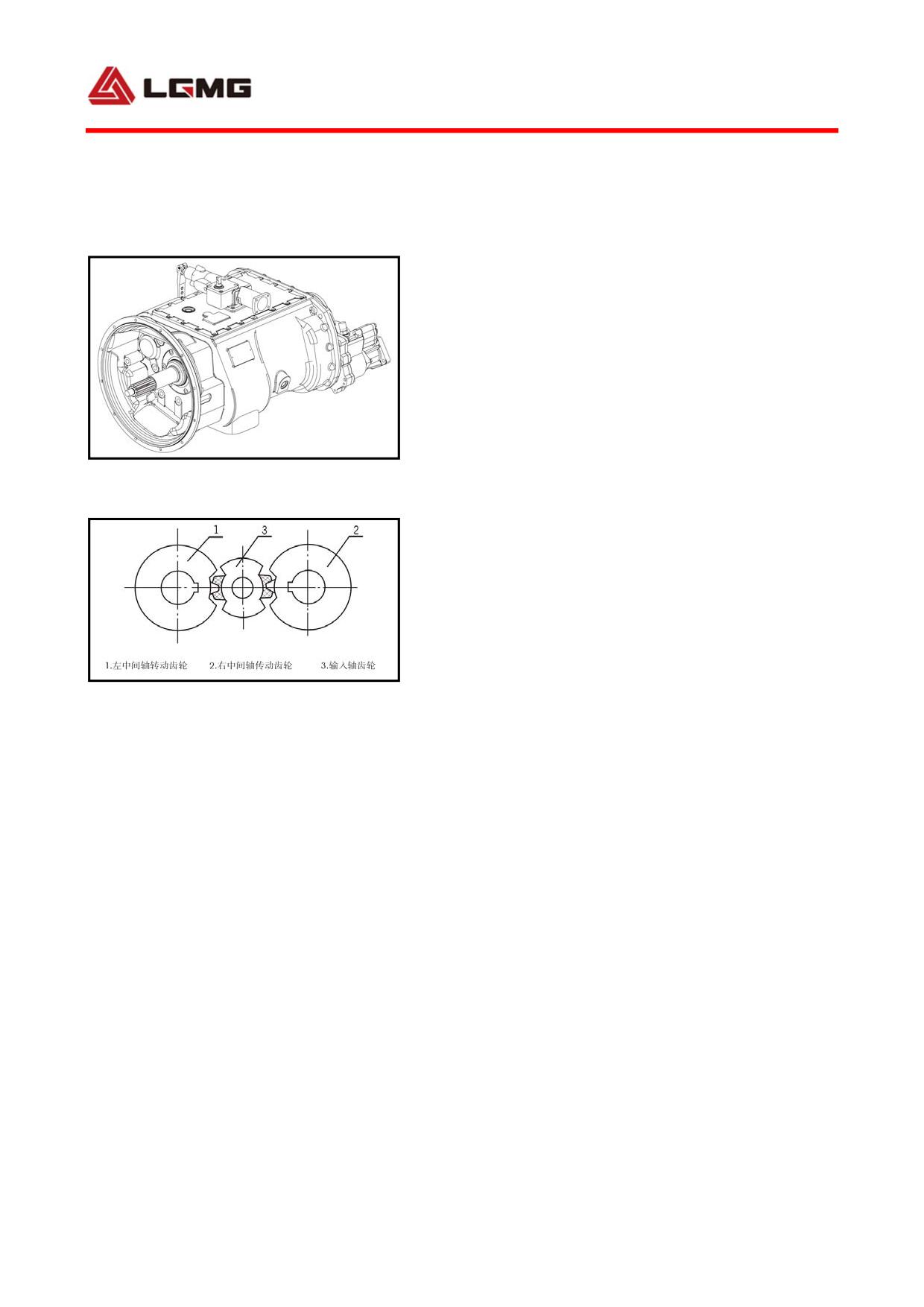
4.4 Operation and maintenance of
transmission
4.4.1 Main performance parameters
The MT86 mining dump truck is applied with the
countershaft and single case structure, which
is designed with seven forward gears and one
reverse gear without synchronizers. The
transmission realizes the gearshift via
Fig 4-10 7DS200 transmission
sliding sleeve, and then the power
transmission through the engagement of the
external and internal splines on the gear with
the sliding sleeves.
The transmission is applied with two parallel
Fig 4-11
countershafts of same structure spaced from
Schematic diagram for tooth alignment of
each other by 180º. The power inputted from the
transmission assembly.
1 Left countershaft gear
input shaft is diverted to the two counter
2 Right countershaft gear
3 Input shaft gear
shafts and finally outputted via the output
shaft after converged. As two countershafts
only transmits 1/2 torque theoretically, the
center distance, gear width, axial size and
weight are reduced accordingly. Thanks to the
twin-countershaft structure, each gear on the
output shaft must be engaged with the two
countershaft gears simultaneously. In
74
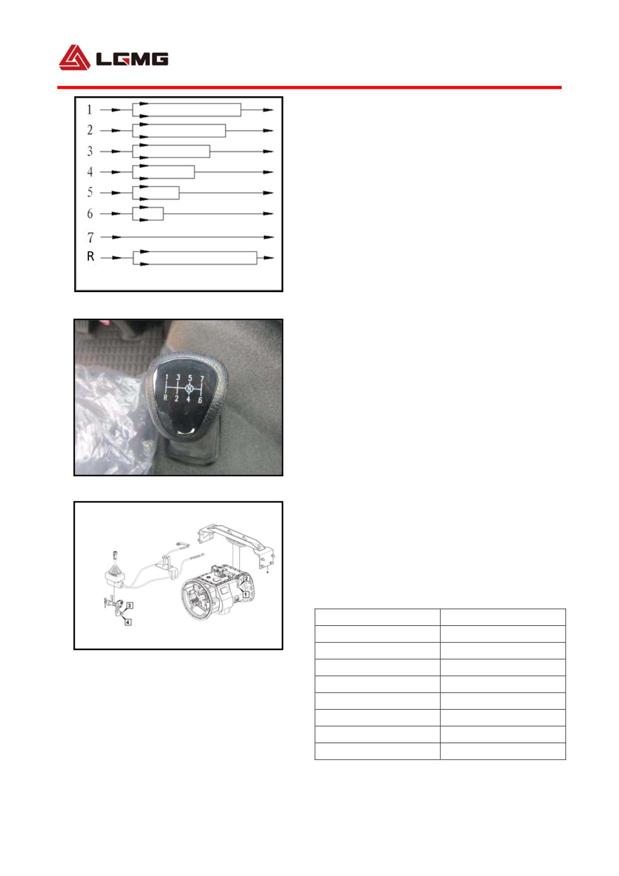
addition, the output shaft gear is radially
floating on the output shaft to make the gear
engaged with the countershaft gear properly
and distribute the load as equal as possible.
Since the output shaft gear floats on the
output shaft, the needle bearing is not
required any more, and the radial forces
applied by the two countershafts to the output
Fig 4-12 Power transmission route diagram
shaft are offset, so that the output shaft only
bears the torque without bending moment, and
the stressing condition of output shaft and
bearing is improved, substantially enhancing
the reliability and durability of the
transmission.
4.4.2 Main performance parameters
Fig 4-13 Shift handle
The maximum input torque is 1,800 Nm, the rated
rotate speed 2,600 r/m, the fuel capacity 23
L, and the gear ratios are given in the table
below.
Gear
7DS200
1
9.14
2
6.7
Fig 4-14 Soft shaft control mechanism
3
4.85
1. Nut 2. Ball hinge 3. Bolt 4. Ball hing
4
3.6
5
2.65
6
1.61
7
1.00
R
8.51
75
The power transmission route is shown in the
figure (left).
4.4.3 Transmission structural parts
1)Installation and adjustment of flexible
shaft control system
The 7DS200 transmission is remotely operated.
The flexible shaft operating system is
installed and regulated as follows:
a. The flexible shaft to be installed to the
truck should have a bending radius not less
than 300 mm, and it is applied within the
temperature range of -40°C~+100°C.
b. The flexible shaft is connected with the
gear shift rocker, and the following
requirements should be met:
1) An included angle of 90 degrees is reserved
between the flexible shaft and the rocker.
2)The guide sleeve and protective pipe joint
of the flexible shaft as well as the pull-push
rod at spatial positions must be in line.
c.The gear and shift flexible shaft shall be
installed to the controller.
! CAUTION: Two flexible shaft ball
joint threads should be screwed down.
d.Position the control lever to neutral
position, measure the flexible shaft at the
76
transmission end to see if it meets the
requirement. And if not, adjust the connecting
length of flexible shaft ball joint with pull
rod thread so as to adjust the installation
dimension of the flexible shaft.
e. Do gearshift after the installation, and
make sure that all gears can be selected. And
if any gear is difficult to be shifted, inspect
and adjust the installation dimension of shift
flexible shaft at the transmission as above.
f.The adjustment of flexible shaft is detailed
as follows:
If, after the assembly is done, the gears at
the front row cannot be engaged properly during
the running-in period, unscrew the nut ① (or
nut ⑤), and anticlockwise rotate (lengthen)
the spherical hinge ② (or spherical hinge ⑥)
properly. On the contrary if the gears at the
rear row cannot be engaged properly, unscrew
the nut ① (or nut ⑤), and clockwise rotate
(shorten) the spherical hinge ② (or
spherical hinge ⑥) properly. Carry out the
steps above repeatedly for adjustment until
all gears can be engaged in place.
2)Power takeoff mechanism
With the adoption of rear power takeoff for the
MT86 mining dump truck transmission, the
77
output rotatory direction and the engine
running direction are consistent. The POT
connects the transmission inner cavity, so it
is unnecessary to add lubricating oil.
The MT86 mining dump truck is applied with the
QH70 power takeoff.
4.4.4 Operation and maintenance
1) PTO
First set the transmission control lever at N,
step on the clutch and close the PTO switch.
When the PTO has gotten the gear engaged,
release the clutch slowly, allowing the PTO to
come into work.
2) Transmission
Operate the transmission reasonably and
properly, and maintain it periodically, which
are very important to ensure a safe and
reliable driving and an extended transmission
life, so please follow the operational
requirements below:
a. Lubricating oil grade
The transmission should be filled with GL-5
gear oil specified in SAE 85W/140.
b. Correct oil level
Make sure that the oil level is up to the sight
glass. The oil level can be inspected through
78
the sight glass of the housing side and add oil
until it spills out of the mouth.
The reference oil capacity of the 7DS200K
transmission is 23 L.
c. Oil level inspection
The oil level should be inspected periodically,
always with the truck parked on a level road.
Due to the volume expansion of hot oil, in order
to avoid any inaccurate measurement, the truck
shall not be inspected immediately after
driving, but be inspected only with a steady
oil level and an oil temperature close to the
normal temperature.
d. Oiling
In order to prevent the lubricating oils of
different types from chemical reaction, always
replenish with the lubricating oil of the same
type with the original one. It is strongly
recommended to use the lubricating oil
approved by LGMG.
e. Lubricating oil change interval
In replacing the lubricating oil of the
transmission, first completely discharge the
existing lubricating oil in the transmission
and clean the strainer assembly. For the new
transmission, after 2,000~5,000 km running,
the lubricating oil has to be replaced. Inspect
79
the lubricating oil for its level and leakage
after 10,000 km, replenish when necessary and
clean the strainer. If the limited period
(mileage) of the mandatory maintenance is
exceeded, change the lubricating oil after
driving for 25,000 km.
f. Working temperature
The transmission in its continuous working
period should have a maximum temperature not
more than 120°C, and a minimum temperature not
less than -40°C. A working temperature more
than 120°C may decompose the lubricating oil
and shorten the service life of the
transmission.
g. Dragging or sliding
While the transmission is working, its
countershaft drives the oil pump to run, and
with the splash lubrication, it can be
lubricated completely. However, in the case
that the truck is dragged with the rear wheel
grounded and drivetrain connected, the
auxiliary and primary shaft gears of primary
transmission do not rotate, but the primary
shaft rotates relative to its gear, so does the
planetary mechanism, which may seriously
damage the transmission planetary mechanism
and the primary shaft locating elements due to
80
lack of lubrication.
To avoid such phenomena, notice that: never
step on the clutch pedal to allow the truck
skidding at natural. To drag the truck, either
pull out the axle shaft or release the drive
shaft, or drag with the driving wheel off the
ground.
! WARNING:
●To avoid personal injury or equipment
fault and damage, please operate the
transmission in accordance with the
specified procedures;
●Before driving, sit in the driver's
seat, set the gearshift lever at N and
pull down the parking brake lever;
●To leave the cab before the truck
starts or while the engine is running,
set the gearshift lever at neutral, and
lock the wheel using parking brake;
●To leave the cab before the truck
starts or while the engine is running,
set the gearshift lever at neutral, and
lock the wheel using parking brake;
81
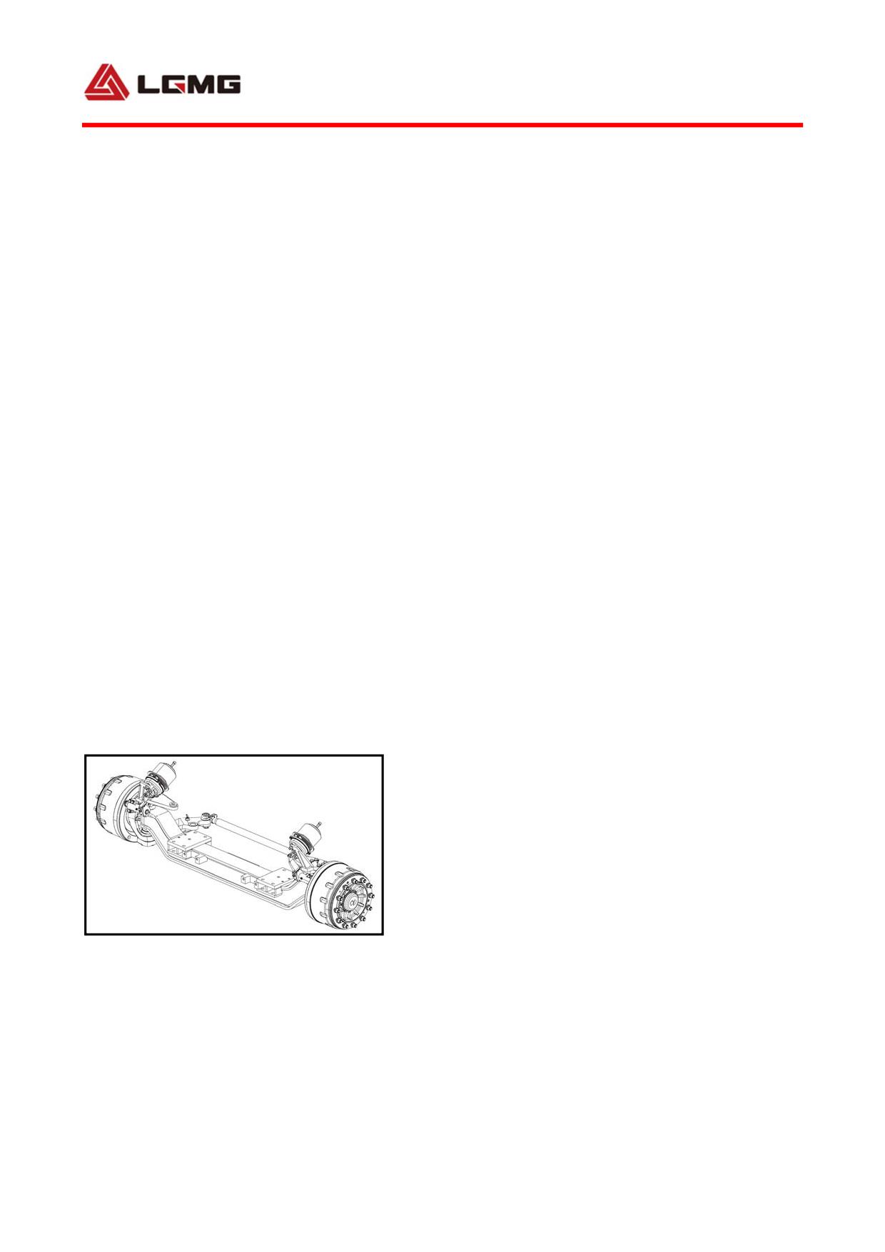
●Before starting, in the case that the
truck air pressure does not reach to a
correct level, never let the parking
brake lever go to do gearshift;
●While the transmission is set at
neutral,never slide downhill;
●To operate PTO, step on the clutch
pedal to the limit immediately after the
PTO switch is pressed, and release it
after the PTO works as normal;
●To operate PTO, step on the clutch
pedal to the limit immediately after the
PTO switch is pressed, and release it
after the PTO works as normal.
4.5 Operation and maintenance of front
axle
4.5.1 The front steer axle and intermediate
and rear drive axles
The front axle of the MT86 mining dump truck
Fig 4-15 Front alxe
is a two stage drive axle with “central 1st
stage reducer + wheel planetary reducer”, and
equipped with casting axle housing, bogie
82
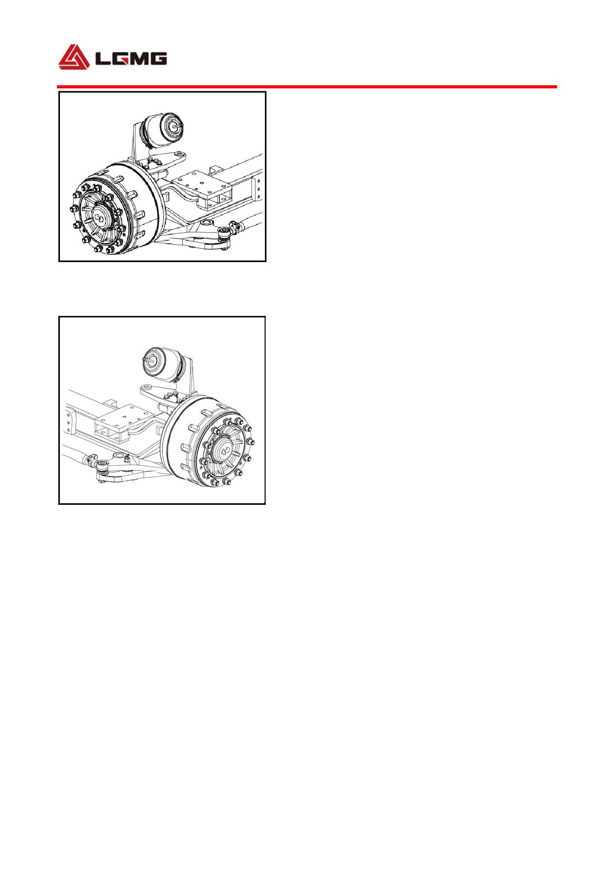
differential and inter-wheel differential as
well as bogie differential lock. An evolvent
S-shaped cam drum brake and external
respiration piston spring brake chamber are
adopted.
4.5.2 Operation and maintenance of front
axle
Fig 4-16 Wheel part
Check if the wheel bolts are loose and the oil leaks
from the wheel rim
1)Operation of front axle
! Warning
● It is prohibited to continue
operating when the axle has failed;
● It is prohibited to disassemble the
truck when the axle has failed;
● It is prohibited to change the axle
Fig 4-17 Front Driving Axle
structure.
Check if connecting bolts between the tie rod and tie
rod arm are loose.
a. Reminder
① It is recommended to replace with
accessories from Lingong Group Jinan Heavy
Machinery Co., Ltd.
② Check and maintain the axle at specified
interval.
b.Precautions for wheel replacement:
● Do not damage threads of the wheel bolts,
and keep the mating surface between the brake
drum and the rim, and the clamping surfaces of
the wheel nuts free from paint, grease and
83
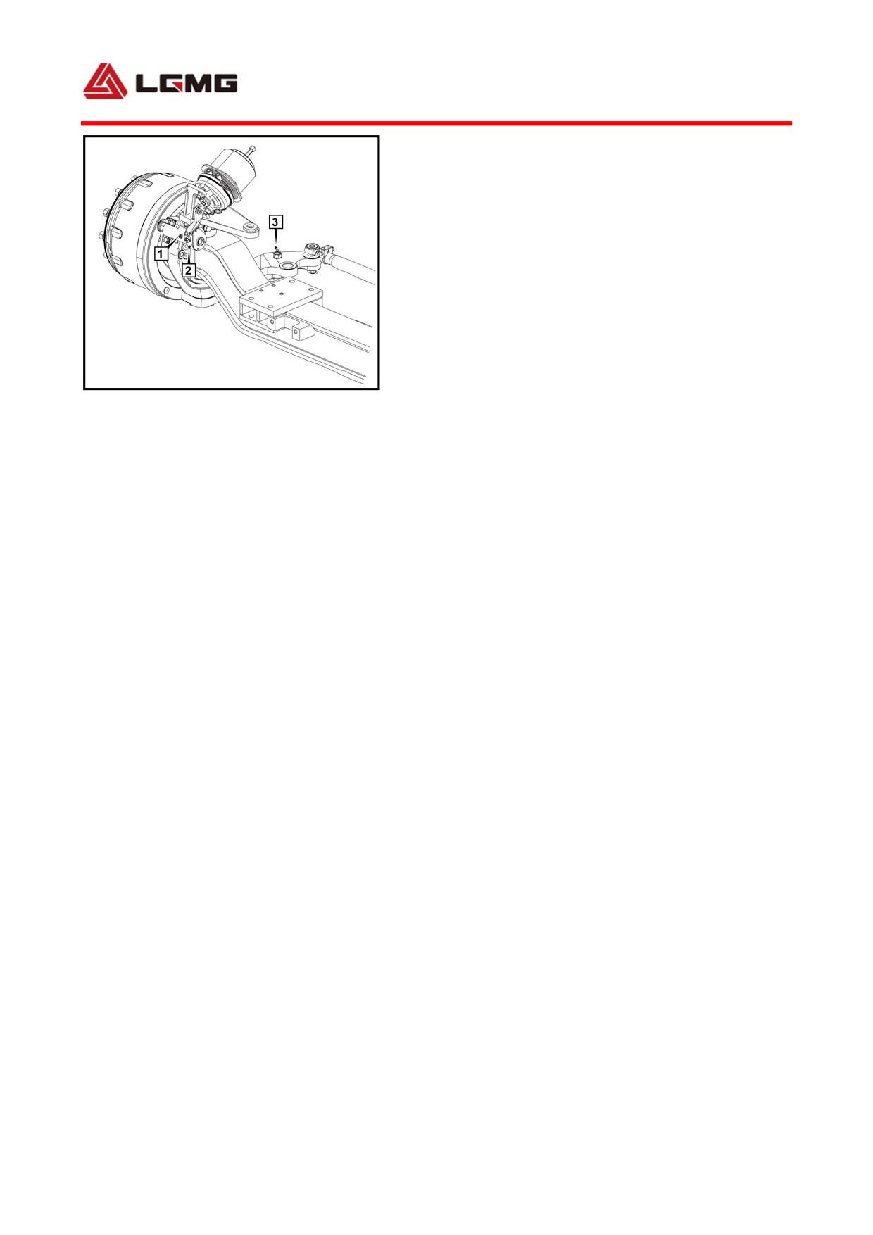
other dirt; apply grease, oil, or other thread
paste to the threads of the wheel bolts and
wheel nuts before installation.
① Clean the matching surface between the
brake drum and the rim, the outer circle
surface between the rim positioning hole and
the wheel rim reduction shell, and the seal
surface of the wheel nut;
Fig 4-18 Front Driving Axle
② Do not damage threads of the wheel bolts,
1. Camshaft support grease nozzle 2. Regulating
and apply grease, oil, or other thread paste
arm grease nozzle
to the threads of the wheel bolts and wheel nuts
before installation;
③ Tighten the wheel nuts diagonally and
evenly, and after each re-assembling of the
tire, the tire nut must be re-tightened after
50 km of travel.
c.Precautions for operation of brake shoe
friction plate:
● When the vehicle has run for the first
5,000km, check the thickness of the brake shoe
friction plate, which shall not to be less than
8mm. The inspection period thereafter may be
shortened as appropriate to avoid other
serious faults due to excessive wear of the
friction plate;
● The clearance between the brake shoe and the
brake drum shall be kept between 0.7 and 1.2
84
mm, and the clearance between the upper and
lower drums and shoes shall not be greater than
0.3 mm;
● The axle friction plate must be accessories
from Lingong Group Jinan Heavy Machinery Co.,
Ltd.
2) Maintenance of axle
a. Routine maintenance
① Check if the wheel nuts are loose and fasten
them before the truck running;
② Check the axle for oil leakage before the
truck running; repair it if any leakage;
③ Check the brake performance and brake
return condition. The brake clearance shall be
between 0.7 and 1.2 mm. In case of improper
brake clearance or poor brake return, check and
regulate immediately;
④ Check if the regulating arm and the camshaft
are jammed. If so, refill grease immediately
to ensure that they rotate flexibly;
Refill grease to the grease nozzle of the
master pin, the camshaft support and the
regulating arm every 15 days. If it is
difficult to refill grease, check it
immediately and stop operating.
b. First maintenance
The first maintenance shall be carried out
85
before 5,000 kilometers (or within 1 month).
The first maintenance items are listed as
follows:
① Refill grease to the grease nozzle of the
master pin, the camshaft support and the
regulating arm as required. If it is difficult
to refill grease, check it immediately and stop
operating;
② Check if the connecting bolts between
components outside the axle are loose and
fasten them;
③ Check and regulate the brake clearance,
which shall be between 0.7mm and 1.2 mm;
c. Periodic maintenance
The periodic maintenance shall be carried out
every 20,000 km or 1 year after the first
maintenance. The periodic maintenance items
are listed as follows:
Repeat the first maintenance items;
Lubricate the brake shoe pin and the brake
roller;
Check the friction plate wear degree. The
thickness of the friction plate shall not be
less than 8mm. Replace it if it is less than
8mm.
! Note: When performing inspection
86
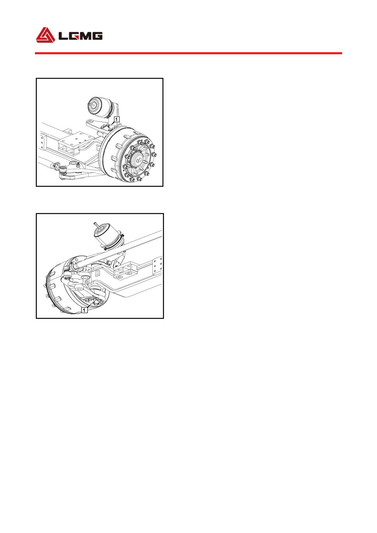
and maintenance, stop the engine, park
the truck on flat road, apply the parking
brake, and set wedges on both wheels of
any axle to avoid safety accidents.
4.5.3 Operation and maintenance of drive
axle
1) Operation of axle
Fig 4-19 Front Axle Part
1. Lower master pin grease nozzle
! Warning
● It is prohibited to continue
operating when the axle has failed;
● It is prohibited to disassemble the
truck when the axle has failed;
● It is prohibited to change the axle
structure.
Fig 4-20 Front Axle Part
1. Upper master pin grease nozzle
a. Reminder
① It is recommended to replace with
accessories from Lingong Group Jinan Heavy
Machinery Co., Ltd.
② Check and maintain the axle at specified
interval.
b. Precautions for differential lock
operation:
The truck shall be stopped or running at low
speed (less than 10 km/h) when the differential
87
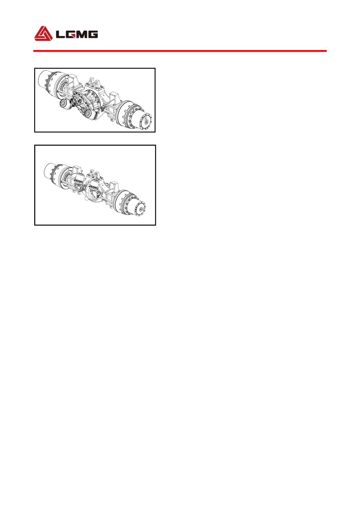
lock is latched to avoid internal gear damage.
When the differential lock between axles is
latched, the truck shall not run for a long time
on undulate road. The differential lock shall
be released in time after the truck has passed
Fig 4-21 Middle axle
the undulate road; otherwise, the internal
parts of the axle may be damaged or the tyre
may be worn.
c.Precautions for wheel replacement:
● Do not damage threads of the wheel bolts,
and keep the mating surface between the brake
drum and the rim, and the clamping surfaces of
Fig 4-22 rear axle
the wheel nuts free from paint, grease and
other dirt; apply grease, oil, or other thread
paste to the threads of the wheel bolts and
wheel nuts before installation.
● Before mounting the wheel, clean the outer
circle between the wheel rim positioning hole
and the wheel rim reduction shell firstly, and
then apply little grease to it.
● Tighten the wheel nuts diagonally and
evenly, and after each re-assembling of the
tire, the tire nut must be re-tightened after
50 km of travel.
d. Precautions for operation of brake shoe
friction plate:
① When the vehicle has run for the first
88
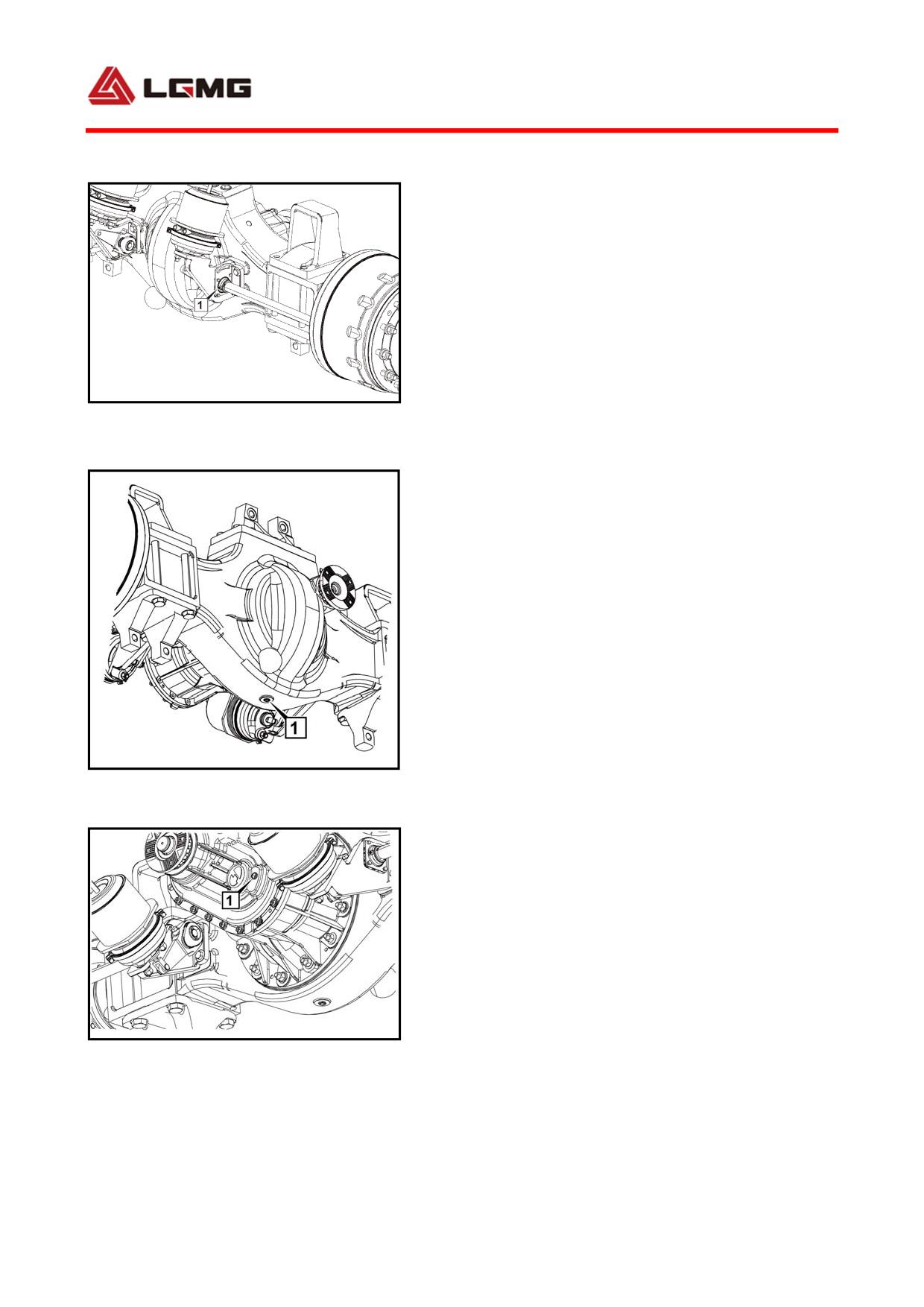
5,000km, check the thickness of the brake shoe
friction plate, which shall not to be less than
8mm. The inspection period thereafter may be
shortened as appropriate to avoid other
serious faults due to excessive wear of the
friction plate;
② The clearance between the brake shoe and the
Fig. 4-23 Rear Axle Part
brake drum shall be kept between 0.7 and 1.2
1. Regulating arm grease nozzle
mm, and the clearance between the upper and
lower drums and shoes shall not be greater than
0.3 mm;
③ The friction plate for each axle shall be
special accessories from Lingong Group Jinan
Heavy Machinery Co., Ltd.
2) Maintenance of axle
a. Routine maintenance:
① Check if the wheel nuts and the oil plug are
Fig. 4-24 Intermediate Axle Part
1. Drain hole
loose and fasten them before the truck running;
② Check the axle for oil leakage before the
truck running; repair it if any leakage;
③ Check the brake performance and brake
return condition. The brake clearance shall be
between 0.7 and 1.2 mm. In case of improper
brake clearance or poor brake return, check and
Fig. 4-25 Intermediate Axle Part
1. Oil level sightglass
regulate immediately;
④ Check if the regulating arm and the camshaft
are jammed. If so, refill grease immediately
89
to ensure that they rotate flexibly;
⑤ Refill grease to the grease nozzle of the
axle every 15 days (as shown in figure). If it
is difficult to refill grease, check it
immediately and stop operating.
b. First maintenance:
① Replacement of grease of drive axle (as
shown in figure above)
Unscrew the drain plug of the axle → drain
grease from the axle → tighten the drain plug
again after the grease has been drained →
unscrew the filler plug of the axle → refill
the grease as required in Table 1 → tighten
the filler plug.
② Refill grease to the grease nozzle as
required. If it is difficult to refill grease,
check it immediately and stop operating;
③ Check if the connecting bolts between
components outside the axle are loose and
fasten them;
④ Check and regulate the brake clearance,
which shall be between 0.7mm and 1.2 mm;
⑤ Remove obstacles from the final drive
reducer vent hole of the middle rear axle
Periodic maintenance:
The periodic maintenance shall be carried out every
10000km
or
1
year
after
the
first
90
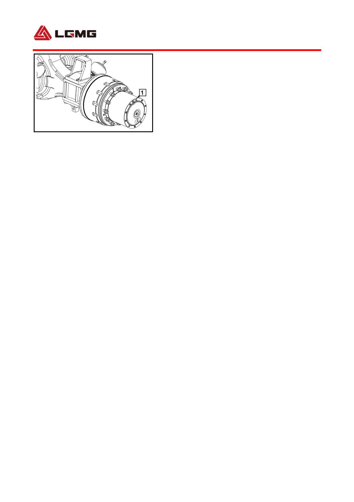
maintenance. The periodic maintenance items
are listed as follows:
① Repeat the first maintenance items;
② Replace the hub bearing grease of the front
axle assembly;
③ Lubricate the brake shoe pin and the brake
Fig. 4-26 Intermediate Axle Part
roller;
1. Oil filler, oil level sightglass, oil drain hold
④ Check the friction plate wear degree. The
thickness of the friction plate shall not be
less than 8mm. Replace it if it is less than
8mm.
! Note:
● After maintenance, the user needs to
check the oil level of the grease every
additional 5,000km or two months, and
refill it at any time;
● Mixing of grease of different
qualities is prohibited;
● When performing inspection and
maintenance, stop the engine, park the
truck on flat road, apply the parking
brake, and set wedges on both wheels of
any axle to avoid safety accidents.
91
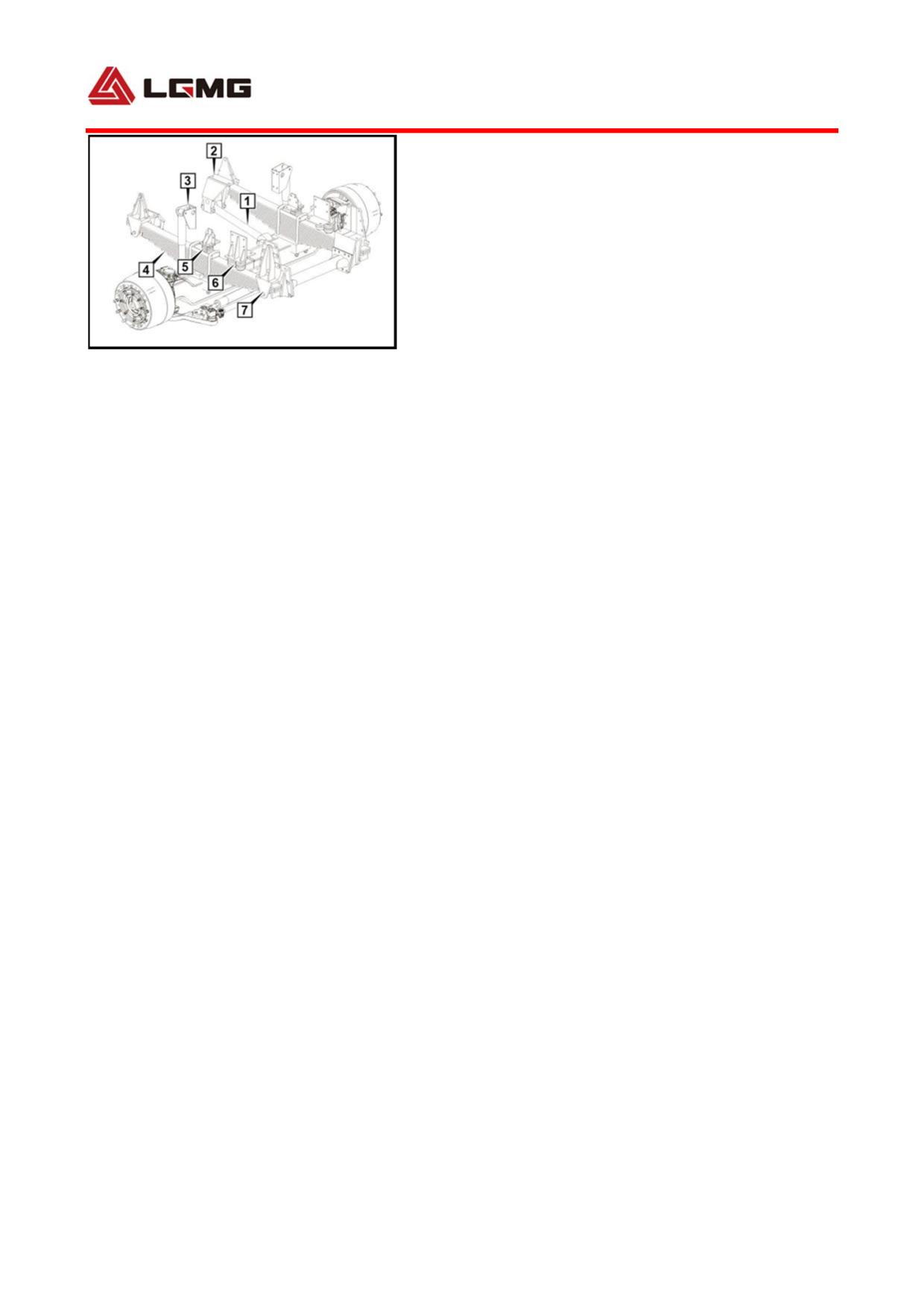
4.6 Operation and maintenance of
suspension system
! Warning: It is necessary to replace
the thrust rod repair kit after the truck
has run for 4 months, (20,000km). The
Fig4-27 Front suspension system
user will bear consequences of vehicle
1. Front push rod 2. Front bearing of the leaf spring
failures due to thrust rod out of limit.
installation 3. Cylindrical shock absorber
4.
!
Caution: It is necessary to replace the
Parallel semiellipse leaf spring 5. Stop block 6. Stop
leaf spring seat wear block after the
block Ⅱ 7. Rear bearing of the leaf spring
installation
truck has run for 4 months (20,000kmM).
! Caution:
1. When the clearance between the guide
cover plate and the leaf spring is ≥3mm,
it is necessary to add adjusting shims to
keep the clearance ≤0.5mm;
2. If the wear extent of the guide cover
plate is ≥ 5mm, it is necessary to
replace it.
! Caution:
92
1. Re-tighten the thrust rod bolts/front
and rear leaf spring bolts periodically
at the interval specified in "5.2 MT86
mining dump truck compulsory maintenance
details". If the engine has operated for
30 hours during the truck shipment
process, the user shall immediately
perform the first re-inspection of the
thrust rod bolts, and re-tighten bolts
every 500 hours (5,000km) after 4-level
maintenance.
2. Push rod bolt re-tightening table
Tightening
Application
Specification
torque*(Nm)
Front push
M20
690Nm
rod bolt
Upper/ lower
thrust rod
M27
1000Nm
bolt
Transverse
thrust rod
bolt
(depending
M24
900Nm
on actual
truck
configuration)
4.6.1 Front suspension system
The front suspension system mainly consists of
parallel semiellipse leaf spring, cylindrical
93
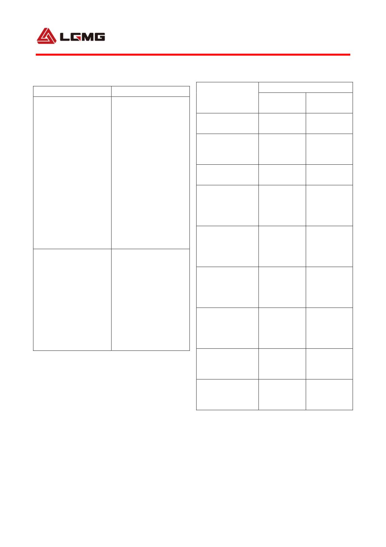
shock absorber, stop block and front push-rod,
Failure Analysis of Shock Absorber
1) Specifications of fasteners
MT86H
Failure mode
Analysis and solution
Application
Tightening
Refill
appropriate
Specification
torque*(Nm)
grease
and then
Front spring
proceed
with
M24
750±50
U-bolt and nut
operation.
If
the
Spring bracket
surface is hot, the
fixing bolt and
M18×1.5
373±37
The shock absorber is
grease is insufficient.
nut
out of work, and there
At this moment, refill
Wear-resistant
is no resistance inside
it.
Otherwise, the
M12×1.25
85±8
block fixed screw
(the shell temperature
shock absorber must
Shock absorber
is not high enough)
have failed. Check if
upper bracket
damage to the oil seal
M12×1.25
85±8
fixing bolt and
and
the
sealing
nut
washer causes oil
Shock absorber
leakage. If so, change
connecting
the washer.
M16×1.5
262±26
upper bracket
It is resulted from
bolt and nut
collision
of shock
Shock absorber
absorber,
steel leaf
lower bracket
spring and frame,
M16×1.5
220±22
fixing bolt and
The shock absorber
deformation of shock
nut
makes a noise
absorber dust-proof
Shock absorber
tube or insufficient
connecting lower
grease. Replace the
M16×1.5
262±26
bracket bolt and
shock absorber or
nut
refill grease.
Stop block
bracket fixing
M16
220±22
bolt and nut
Wear-resistant
block fixed bolt
M12
85±8
and nut
* indicates recommended value, and the
permissible tolerance is within 6%. To
ensure driving safety, it is required to
regularly check the tightening torque of
94
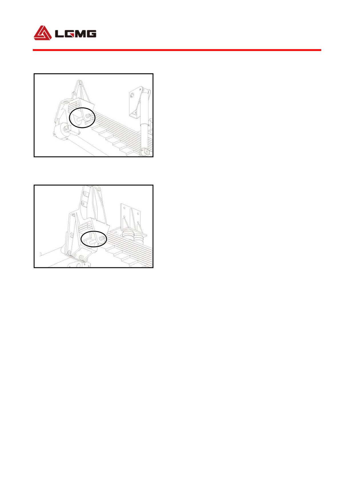
above fasteners.
2) Description of front leaf spring
MT86H: 13 pieces in total, in which four main
leaves, reinforced parallel semiellipse front
leaf spring.
The leaf spring configuration for each model
has already been justified by vehicle
Fig 4-28 Front bearing of front leaf spring
performance test. It is not allowed to make
modification without approval; otherwise it
may lead to the system no longer in harmony with
others or vehicle out of control which would
cause unnecessary personal injury and property
loss.
3) Fault diagnosis
The faults in front suspension system may be
Fig 4-29 Rear bearing of front leaf spring
relating to multiple systems, including
steering gear, front axle, tires, wheels, etc.
When abnormal conditions occur during driving
(such as noise, running deviation, vibration
and abnormal damage), stop the vehicle
immediately and do a thorough inspection to
calibrate the items relating to the following:
a. If pressure of tires is normal;
b. If tires have non-uniform wear;
c. If tires are in unbalanced or damaged;
d. If the fasteners of each bracket are loose;
e. If steering components are worn and loose,
95
such as tie rod ball;
f. If suspension components are damaged and
loose, such as wear resisting washer between
lifting lug and leaf spring eye or bracket;
g. If front axle and wheel alignment is
correct;
h. If lubrication failure and “oil, water or
air leakage”.
i. If the cylinder type shock absorber is
malfunction( Shock absorber failure analysis
as shown by the left table );
4) Service and maintenance
a. Leaf spring plate and clip should be
replaced in time. These components are prone
to be damaged under overload and severe road
conditions. Once damaged parts are found,
replace or repair them immediately; otherwise
it may lead to major accident.
b. Leaf spring stop bolt should be checked and
lubricated timely so as to ensure normal
operating of suspension system.
c.Bolts, nuts and leaf spring center bolts
should be retightened every 1,500 km according
to relevant torque requirements.
d. Once stop block is damaged or missing,
replace it timely; otherwise it may lead to
excessive jumping of axle which will
96
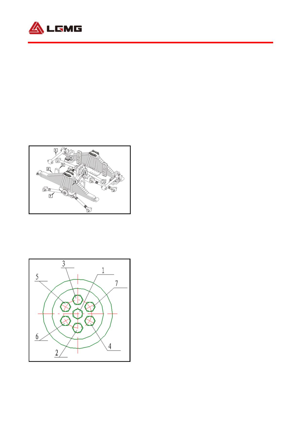
accelerate break of leaf spring plate.
e.If the wear extent of the wear block exceeds
50% total thickness or it fall off, replace it
immediately; otherwise, the leaf spring seat
will be damaged, thus influencing the service
life of the seat;
f. If resistance is insufficient or any sound
occurs due to insufficient oil or leakage of
telescopic shock absorber, immediately repair
or replace it; otherwise, comfort of the truck
will be greatly degraded and even serious
accidents may occur;
4.6.2 Rear suspension system
Fig 4-30 Rear suspension system
The rear suspension system mainly consists of
1.transverse thrust rod 2. parallel semiellipse
leaf spring
3.guide plate
4. upper push rod
reinforced integral balance shaft, parallel
5.enhanced maintenance-free balance shaft
semiellipse leaf spring, unilateral 4-M30 bolt,
6.bolt 7. lower push rod
and upper/lower push rod.
1)Specifications of fasteners
* indicates recommended value, and the
permissible tolerance is within 6%. To ensure
driving safety, it is required to regularly check
the tightening torque of above fasteners.
Fig.4-31 Disassembly order
97
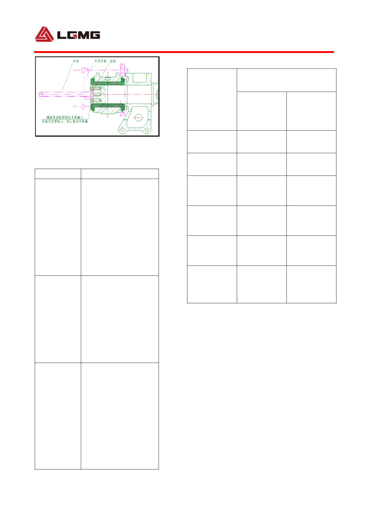
MT86H
Application
Tightening
Spec.
torque*(N.m)
Rear spring
M30
1300±50
bolt and nut
Fig.4-32
Stud bolt and
Malfunction table of rear suspension
M18×1.5
373±37
nut
Fault mode
Solutions
Clean the balance shaft
S op block
bracket fixing
M14
140±14
housing cver and ensure
bolt and nut
good cntact flatness with
Oil leakge due
shaft housing. Replace
Stop block
to sealing
fixing bolt
M12
48±4
the U-ring and do the
failure of
and nut
assembly. Replace the
balance shaft
balance shaft housing
Guide plate
housing cover
cover and assemble it
fixing bolt
M14
140±14
and nut
according to the above
procedures.
Push rod
Replace the bolts, apply
upper bracket
M16
262±26
fixing bolt
thread locker on new
and nut
M16×1.5 bolts
bolts, tighten them to
on both ends
required torque, lock the
of balance
stop washer, and install
shaft getting
the balance shaft housing
2) Description of rear leaf spring
broken
cover. Assemble it
according to the above
MT86H: 15 pieces in total, in which five main
procedures.
Replace the whole set of
pieces, reinforced parallel semiellipse leaf
bearing and adjust the
bearing clearance to
prevent bearing from
breaking again due to
Crack in
local stress of bearing
bearing
caused by axial
transmission of shaft
housing. Assemble it
according to the above
procedures.
98
spring.
Fault mode
Solutions
The leaf spring configuration for each model
Replace the sealing ring.
For specific procedures,
Oil leakage
has already been justified by vehicle
refer to paragraph a.
due to sealing
Removal, installation and
performance test. Modification without
ring failure
adjustment of balance
approval may lead to major fault and loss.
suspension assembly.
Replace the balance shaft
3) The balanced suspension assembly is rubber
Break in
housing and components
balance shaft
and assemble it
maintenance-free balanced suspension. The
housing
according to the above
disassembly and assembly process is as
procedures.
Crack or break
Replace the shaft &
follows:
in bracket
bracket assembly.
Crack or break
a. Disassembly of the suspension:
Replace the shaft &
in balance
bracket assembly.
shaft
① Unscrew the fastening bolts successively
Crack or break
Replace balance shaft
in balance
and evenly with an air wrench, to separate the
housing and components
shaft housing
bearing block from the balance shaft. (Note:
Check center bolt for
Pieces around
break, and replace it in
The disassembly sequence is as shown in the
leaf spring
time; or check and
left figure. When disassembling the bolts, do
retighten bolt and nut.
not completely unscrew a bolt in one time, but
repeat the unscrewing process for many times,
to prevent the threads from being damaged.)
② Use special tools to clamp the bearing
retainer and push the screw against the block at
the external end face of the balance shaft (to
prevent the screw from damaging the threads of
the balance shaft). Disassemble the bearing
retainer, rubber bearing and balance shaft
casing and other parts as a whole by the torque
99
of the screw, and separate them from the
balance shaft. The sketch map is as shown in
the left figure.
③ Take the rubber bearing out of the balance
shaft casing from the two ends.
b. Assembly of the suspension:
① Put the rubber bearing into the cleaned
balance shaft casing or a new balance shaft
casing.
② Spray fresh water or 10% suds on the
surface of the balance shaft or inside the rubber
bearing, to reduce the resistance of mounting
the balance shaft casing and rubber bearing into
the balance shaft.
③ Mount the balance shaft casing and rubber
bearing into the balance shaft. It is required to
horizontally move them into the balance shaft
and the balance shaft casing can be properly
rotated, to ensure successful assembly. The
mounting surface of the spring of the balance
shaft casing shall be level after the assembly.
④ Apply gear oil or lube on the surface of the
bolts, to prevent ablation of the bolts during the
fastening.
⑤ After the bolts are fastened, the user can test
100
if the end face of the bearing block cling to the
end face of the balance shaft through the upper
and lower measuring holes, if the depth at the
two measuring holes are the same and if the
depth meets or is close to the theoretic depth
(The theoretic depth is 35±0.1 mm).
! Note: Because of large axial
compression of the rubber bearing (more
than 20 mm) and the features of rubber,
when fastening the bolts with an air
wrench, the user needs to repeat the
fastening for many times. It is
recommended to fasten the bolts
alternately with a torque wrench after
the bolts are fastened to a certain
degree (when the fastening effect of air
wrench is not clear), until the torque of
the 7 bolts all reaches 540-600 N.m.
4) Service and Maintenance
a. Frequently check the following parts: check
upper/lower push rod and the connecting bolts
for damage and looseness. Check stop block for
dropping, leaf spring for break or dislocation
and leaf spring pressure block for crack.
b. Besides handling mandatory maintenance,
retighten the nut of bolt every 1,500-2,000 km
according to specified torque requirements.
101
! CAUTION: Do not change the number
of leaf springs or replace them with ones
of different thickness without approval.
What is more important, do not modify the
suspension structure without
authorization! Do not use unaccepted
components by our company such as push
rod, slide plate seat and guide plate.
The modified or replaced parts may not be
applicable to the suspension of this
model, which would lead to unnecessary
fault and loss.
c. Paint lubricating grease around the leaf
spring and the sliding plate every 8,000 to
10,000km. Use the adjusting shim to adjust the
clearance between guide plate and leaf spring
to be 0~1mm;
d. The normal wear limit life of guide plate and
slide plate seat is half a year. If they are in
serious wear, replace them immediately. If slide
plate seat appears as shown left, it indicates it is
in severe wear.
! CAUTION: The guide plate belongs
to the split type and when it has been
worn down for 5mm, replace it
immediately.
102
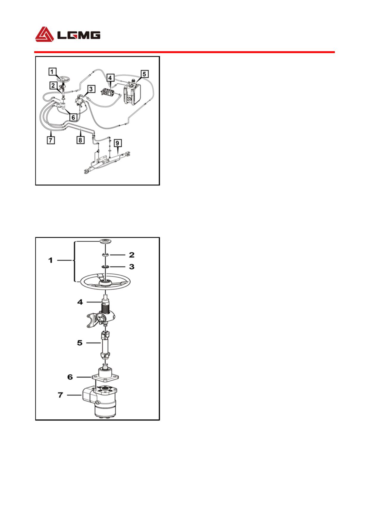
4.7 Operation and maintenance of
steering system
The steering system consists of a steering control
system and a hydraulic power steering system. The
steering system consists of a steering wheel, a
steering column, a steering drive axle, a pilot valve, a
vane pump, a hydraulic oil, a steering gear, an oil pipe,
a steel pipe, a steering cylinder, etc., as shown in left
Figure 4-33. In order to adapt to harsh operating
conditions, the hydraulic power steering system
consists of an internal power steering system and a
external power steering system.
Fig 4-33 steering system Structure diagram
1. Steering wheel 2. Steering column and steering
4.7.1 Steering control system
drive axle 3. Pilot valve 4. Vane pump 5. Hydraulic oil
tank 6. Steering gear 7. Oil pipe 8. Return steel pipe 9.
It consists of steering wheel and steering column with
Steering cylinder
adjustable height and angle. The diameter of steering
wheel is Φ480 mm.
As shown in Figure 4-34, the steering wheel 1 is
mainly composed of a rim, a spoke and a hub. The
lower part is in wave shape to facilitate the driver grip.
The steering wheel 1 and the steering drive axle 5 are
generally splined and the ends are fixed with nuts.
The steering drive shaft 5 passes through the steering
column 4 with the lower end connected witn the
steering gear 7, to transmit torque between them, for
which the energy absorption type steering axle is
used.
In addition to the conventional steering function, the
steering control system can effectively absorb impact
energy at collision, and buffer the impact of the
steering wheel to the driver. Basic principle: axial
displacement will occur when the steering drive shaft
is subjected to great impact, and energy is absorbed
by the deformation of the steering column or the
dislocation of the steering drive shaft.
Fig 4-34
Steering control system is of continuous and
1. Steering wheel 2. Nut 3. Washer
adjustable type. With this system, the height range of
4. Steering column5. Steering drive axle
steering wheel is ±25mm, and the angle range is ±5°.
6. Support 7. Steering gear
Specific adjusting method: Unscrew adjusting handle
as shown, adjust steering wheel 1 to appropriate
103
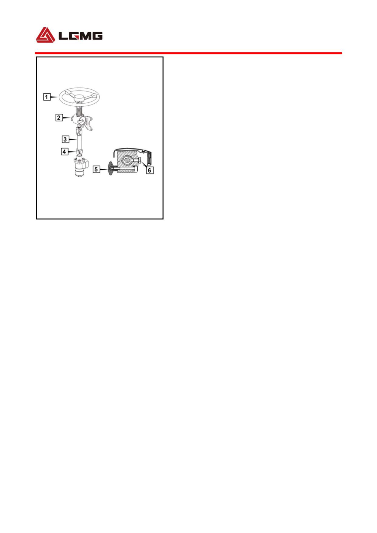
operating position, and tighten the adjusting handle .
4.7.2 Hydraulic power steering system
Full-hydraulic steering gear, pilot valve,
hydraulic oil pump, hydraulic oil tank,
steering cylinder, hydraulic pipeline, etc.
The steering cylinder is φ70.
1) Full-hydraulic steering system
construction (as shown in Figure 4-33)
2) Full-hydraulic steering system principle
The steering pump is a vane pump. The engine
Fig 4-35 Structure Diagram of Steering System
is directly connected with a power takeoff at
Operating Device
1. Steering wheel
2. Steering column
the position of engine power take off, and
3. Steering drive axle
4. Universal joint
keeps running. The steering pump sucks oil from
5. Regulating handle
6. Travel limit screw
the hydraulic oil tank and outputs
high-pressure oil to a pilot valve P opening.
The pilot valve has following 5 openings: P,
EF, CF, and Ls. Excessive hydraulic oil of the
steering system returns to the oil tank via EF
opening. CF opening is connected with
full-hydraulic steering gear P opening to
provide high-pressure oil to the steering gear.
Ls opening is connected with steering gear Ls
opening as a control line. When the steering
wheel drives the steering gear to rotate, the
steering gear Ls opening provides a pressure
signal to the pilot valve Ls opening to enable
104
the pilot valve rod operate. When the pilot
valve P opening is connected with CF opening,
the high-pressure oil flows to the steering
gear, passes through the valve element passage
in the steering gear, to the steering gear L
opening or R opening, and to the steering
cylinder. The big cavity of the left steering
cylinder is connected with the small cavity of
the right steering cylinder, and the small
cavity of the left steering cylinder is
connected with the large cavity of the right
steering cylinder. Both oil cylinders operate
jointly to drive the front wheels. When the
steering wheel moves slowly or does not operate,
most of the hydraulic oil from the steering
pump returns to the tank via the pilot valve
EF opening. The pilot valve T opening is
connected with the oil return opening of the
hydraulic oil tank. The steering gear has
following five oil openings: P, R, L, Ls and
T. P opening and Ls opening are connected with
corresponding openings of the pilot valve and
are not described again herein. When the
steering wheel rotates rightwards, R opening
outputs high pressure. R opening is connected
with the rod cavity of the right steering
cylinder (the rodless cavity of the left
105
steering cylinder). L opening is connected
with the rod cavity of the left steering
cylinder (the rodless cavity of the right
steering). The steering gear T opening is
connected with the oil return opening of the
hydraulic oil tank.
3) Full-hydraulic steering system maintenance
a. Check the oil level in the hydraulic oil tank:
First, clean the oil tank and periphery to
prevent dirt contamination. During inspection,
pay attention to the scale on the oil level
gauge. When engine is running, the hydraulic
oil level is even with the central scale of oil
level gauge; when engine does not work, the
hydraulic oil level will be a little higher
than the central scale.
b. It is required to change hydraulic oil for
a new vehicle after it runs 2500km, and
meanwhile clean the filter element. Change
hydraulic oil every 10000km or every year
thereafter.
c. Check oil level every week, and check the
cleanness of hydraulic oil.
d. The method of oil change is as follows:
① Support front shaft;
② Unscrew oil filling breather filter;
③ Start engine, run it at idle speed for 10s,
106
and turn steering wheel left and right to limit
positions for several times to discharge oil
from the oil tank, booster pump, steering gear
and booster cylinder;
④ Retighten the oil return pipe (note that it
is required to keep it clean and prevent dirt
and foreign material contamination), and clean
oil tank, oil filling breather filter and
filter element. It is preferred to replace it
with a new filter element at every oil change.
⑤ When the oil filter is filled with hydraulic
oil, run the engine at idle speed, turn the
steering wheel left and right for several times,
and at the same time, keep supplementing oil
till the oil level does not lower and is within
the range and no bubble appears.
! CAUTION:
● The machine as delivered uses L-HM32
hydraulic oil. The users can change to
the L-HM46 hydraulic oil. It is strictly
prohibited to use the two oils mixed.
e. During maintenance, it is required to check
the clearance between moving parts, such as tie
rod and drag link joints. If the clearance is
too large, replace parts immediately. It is
also required to add grease to each grease tap
107
for maintenance.
4)
Important connected positions and
tightening torque requirements.
Torque
No. of
Name
Spec.
( Nm)
places
Steering wheel
M22*1.5
580±58
1
fixing nut
Steering gear
M10*35
48±4
4
fixing bolt
Booster cylinder
M16×45
220±22
6
bracket bolt
Drag link lock
M12×1.5
85±8
2
nut
108
5) Common fault causes and troubleshooting methods
Common faults
Causes
Troubleshooting methods
1. Oil in oil tank is insufficient
1. Check oil level of oil tank and refill
2. Air invades into oil passage
it as specified
3. Filter or oil passage is blocked
2. Exhaust and check oil level and
4. Oil pump pressure is insufficient
tightness of pipeline connectors
5. Inner leakage of steering gear is
3. Clean filter or dredge or replace
severe
oil passage
Hard steering
6
Front
wheels
(braking
4. Maintain oil pump
non-return) are blocked
5. Identify leakage and repair
7. Tire pressure is insufficient
6. Regulate or replace it
8. Steering column interferes with
7. Inflate
universal joint
8. Adjust it
9. Overload
9. Reduce load
1. Check and replace oil seal or O
1. Oil seal or O ring is damaged
ring
Steering gear oil
2. Oil pipe is damaged
2. Check and replace oil pipe
leakage
3. Oil pipe joint leaks oil
3. Replace sealing ring and tighten
4. Oil viscosity is insufficient
connectors
4. Use oil properly
1. Level is too high
1. Adjust it
Oil spillage from oil
2. Oil inlet is blocked
2. Dredge oil passage
tank
3. Oil pump is worn
3. Replace it
1. Tire pressure is insufficient
1. Inflate
2. Air invades into oil passage
2.
Perform maintenance and
3. Oil return hose is twisted and
exhaust
Hard steering reversal
blocked
3. Replace it
4. Steering valve is jammed
4. Regulate or replace steering valve
5. Steering gear is too tight
5. Adjust clearance
6. Connection is loose
6. Check and adjust it
1. Steering valve is asymmetric
1.
Regulate or replace valve
2. Control valve is blocked with dirt
assembly
3. Leakage at both sides of steering
Different left-right
2. Clean control valve
gear differs
steering degree
3. Replace sealing ring
4. Air exists in single cavity
4. Exhaust air
5. Master pins and camber of tires
5. Adjust parameters of truck
at both sides are asymmetric
1. Oil in oil pump is insufficient
1. Maintain oil pump and refill oil
2. Inner leakage of steering gear is
2. Maintain and replace seals
Heavy fast steering
severe
3. Check tightness and connections
3. Air invades into oil passage
and exhaust air
109
Common faults
Causes
Troubleshooting methods
1. Oil pipe is bent
1. Clean or replace it
High oil temperature
2. Oil passage is blocked
2. Dredge oil passage
1. Steering shaft has jammed
1. Check jamming position and
2. Steering valve is asymmetric
check if input axle is subjected to
3. Flow of oil pump is excessive
radial shear
4. Oil is too dirty and steering valve
2. Regulate or replace valve
cannot return immediately
assembly
Run-off
5. Wear or pressure of tires on both
3. Regulate or replace oil pump
sides differs greatly
4. Clean and change oil
6. Bubbles exist in oil and direction
5. Replace tire or inflate
is unstable
6. Check and exhaust air
7.
One front wheel (braking
7. Maintain brake
non-return) is blocked
1. Air invades into oil passage
2. Oil level of oil tank is too low,
and oil pump sucks air
3. Steering system connections are
1. Identify leakage and exhaust air
loose or worn severely
2. Identify leakage, refill oil and
4. Flow of oil pump is too low
exhaust air
5. Steering gear control clearance is
3. Maintain or replace connections
Jitter and drift
large
4. Regulate or replace it
6. Steering gear mounting bolt is
5. Adjust clearance
loose
6. Fasten it
7. Tire pressure is insufficient or
7. Inflate
pressure of tires on both sides
8. Replace it
differ
8. Tire is worn severely or wear is
uneven
1. Air invades into oil passage
2. Oil level of oil tank is too low
1. Check air leakage position and
3. System inlet and outlet pipes are
exhaust air
bent, and oil passage is blocked,
Abnormal sound of
2. Identify leakage and refill oil
etc.
steering
3. Dredge oil passage
4. Displacement of oil pump is
4. Replace oil pump
unstable
5. Remove or replace it
5.
Steering
control
valve
performance is poor
110
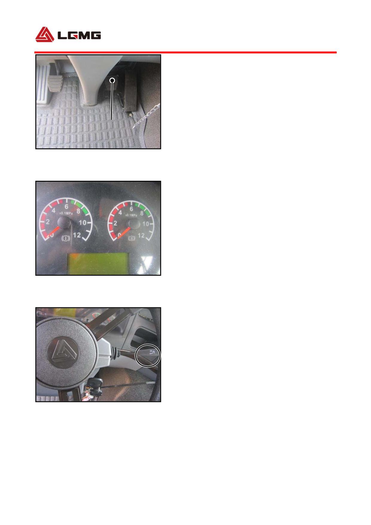
4.8 Operation and maintenance of brake
system
4.8.1 Composition of brake system
The brake system of MT86 mining dump truck
1
mainly consists of two-circuit service brake
(foot brake), auxiliary brake (engine exhaust
Fig 4-38
brake) and emergency/parking brake (hand
1. Brake pedal
brake).
The two-circuit pressure brake is operated
through the pedal. Its working pressure is 0.8
Mpa, and the disconnection pressure of
pressure regulating valve is 0.85 Mpa. The
first circuit acts on wheels of middle and rear
axles, and the second circuit acts on the
Fig 4-39 Brake pressure gauge
wheels of front axle. Once the pressure in one
of air reservoirs of the two circuits is below
0.55 Mpa, the low brake pressure warning
indicator on instrument panel will light up,
and at this moment, it is required to stop the
vehicle immediately and find out the causes of
pressure falling.
Continuously and repeatedly applying full
Fig 4-40 Exhaust brake rocker handle
brake in a short time may also lead to pressure
falling below 0.55 Mpa.
Criteria for pressure inspection: Shut off
engine and apply hand brake. In 2h, the
111
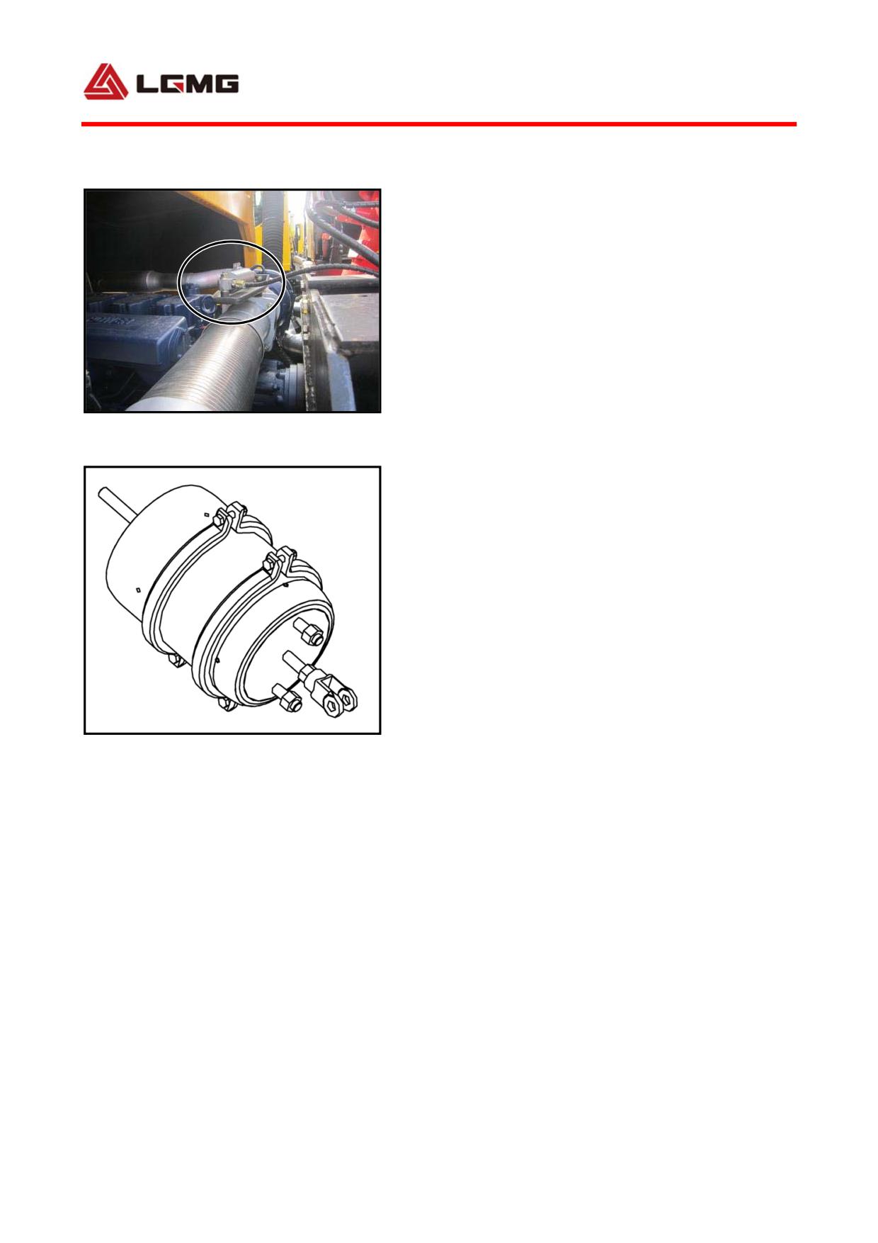
pressure falls by 0.05 Mpa at most or in 30 min,
it falls by 0.01 Mpa at most.
! CAUTION: Do not adjust the release
pressure of pressure regulating valve
without approval.
4.8.2 Engine exhaust brake
Fig 4-41 Exhaust butterfly valve
The MT86 mining dump truck is equipped with the
function of engine exhaust brake. After you
press the exhaust brake switch, the running
vehicle can utilize the energy from engine for
auxiliary brake.
When driving down a long slope, be sure to use
the exhaust brake. In case of running on icy
or muddy road, the use of exhaust brake can
reduce the risk of side slide. In the event of
Fig 4-42 Brake chamber
meeting other vehicles or passing through poor
road, it is better to use the exhaust brake to
accelerate. The use of auxiliary brake can
reduce the times of applying main brake, which
will reduce the wear and heat of wheels and
final drive so as to extend their service life,
reduce fuel consumption and increase driving
safety. After driving down a long slope, simply
check the performance of the exhaust brake.
△! CAUTION: When transmission is in neutral
112
and the clutch is released, the auxiliary brake
will not work. When the speed of engine is lower
than
1,100 r/min, the auxiliary brake will not work.
The exhaust braking efficiency is higher at low
gears.
4.8.3 Emergency and parking brake
The hand brake can be used for emergency
braking and parking brake. It works via the
energy storage spring brake chamber of axle.
Parking brake can be realized by operating the
hand brake valve handle. When brake system is
in failure, relying on the push of energy
storage spring, the emergency braking can be
realized automatically. Only when the pressure
in brake system is above 0.55 Mpa and the
parking brake indicator goes out can spring
braking be released.
Apply: Pull the handle. At the same time, the
parking brake indicator on instrument panel
will light up.
Release: Lift the hand brake valve handle and
loosen it, which will return to release
position automatically. At the same time, the
parking brake indicator on instrument panel
will go out.
113
If braking is activated automatically due to
leakage from air pipe connected to the spring
brake chamber, it is only needed to unscrew the
bolt at the rear end of spring brake chamber
to release position, and the braking will thus
be released (see the figure left).
CAUTION:
● When stopping vehicle, be sure to
pull down the hand brake valve handle!
● Before starting the engine, be sure
to place the hand brake valve at braking
position; otherwise after the engine
starts the parking brake will be released
automatically due to pressure rising in
system.
● Before parking brake indicator goes
out, do not start the vehicle.
● Under certain conditions, the
braking force of parking brake may be
insufficient to park a fully loaded
vehicle on a slope. Therefore, when
parking the vehicle on a slope, wedge the
wheels for safety.
114
4.8.4 Quick joint
The pipes of the vehicle are mainly equipped
with Jietong quick joints so as to make the
tightness of brake system better.
! CAUTION: The removal of pipe joint
without using special tools may lead to
component damage, and the air tightness
will not be guaranteed when it is
refitted.
4.8.5 Operation of inflation joint
Due to the installation of combined air drier,
the pressure regulating valve is integrated
with the air drier, and the inflation joint is
installed at the air drier outlet.
Connect the joint to an inflation hose to
inflate tires and supplement air to air pipes
of the vehicle from outside air source.
4.8.6 Inspection and replacement of dryer
The dryer is able to continuously and
effectively absorb the moisture in the
compressed air, so as to keep the brake system
in good operating status. Drying effects of the
installed air dryer have to be regularly
115
checked.
1) Check method: For the truck equipped with
an air dryer, regularly check accumulated
water in the air reservoir (recommended
monthly). When accumulated water is found in
the air reservoir furthest from the dryer, it
indicates that the desiccant has failed, and
the drying cylinder should be replaced.
2) Replacement method: 1) Unscrew the top nut
of the dryer, remove the old drying cylinder,
clean the connecting bolt and the valve body;
2) uniformly apply one pass of grease onto the
sealing and matching parts between the new
drying cylinder and the valve body, and apply
little thread locker onto the matching part
between the new drying cylinder and the
connecting bolt; 3) Screw the new drying
cylinder onto the valve body to the maximum
torque of 15NM.
4.8.7 Maintenance of brake line
When doing welding, cutting or drilling next
to plastic brake pipe, follow the rules below:
1) Bleed air from pipes at first;
2) Cover pipes against sparks, flame and hot
chips;
3) The non-pressure pipe is allowed to be
116
subject to Max. temperature of 130℃ for 1 h.
4.8.8 Braking operation
To stop the vehicle, follow the steps below:
1) When the vehicle is running, first release
the accelerator pedal to reduce vehicle speed.
2) When the vehicle approaches the stopping
position, slightly depress the brake pedal to
stop the vehicle slowly.
3) When the vehicle is stopped stable, engage
the transmission in neutral and pull down the
parking brake valve handle to make the vehicle
in parking brake state. When applying the brake,
note the following:
1) When applying the brake, except for
emergency conditions, do not quickly depress
the brake pedal hard to the bottom and keep
depressing it, which may cause personal injury
or lead to component damage.
2) Avoid continuously depressing the brake
pedal in a short time and for many times so as
to prevent huge consumption of compressed air
in the air reservoir which will affect the
braking performance of vehicle and lead to the
vehicle out of control further.
3) Do not frequently use the service brake;
otherwise it may lead to brake overheat which
117
will significantly affect brake effect.
4) It is not recommended to use the emergency
brake under non-emergency conditions.
Especially when running on a wet and slippery
road, the vehicle may be at a risk of side slide
if the emergency brake is applied.
5) After the vehicle cleaning or vehicle
passing over deep puddle, water may enter the
brake drum, which will reduce the braking
effect of the vehicle. Under this condition,
run the vehicle at a low speed and gently
depress the brake pedal for several times to
drain water so that the brake can work
normally.
6) When the vehicle is running, if the low
pressure warning indicator of brake system
lights up, it is required to stop the vehicle,
find out the causes and do troubleshooting.
4.8.9 Parking
1) After stopping the vehicle, do not shut the
engine off immediately. Always run the engine
at idle speed for 3~5 min before shutting it
off so that the temperature of engine coolant
can decrease. Especially after the engine runs
at heavy load and the vehicle runs at a high
speed, it is required to run the engine at idle
118
speed before shutting it off; otherwise it may
lead to faults such as cylinder scoring and
supercharger damage.
2) After the engine shuts down, disconnect all
switches, and at last disconnect the master
power switch on the body of battery box.
! Warning:
● Avoid parking the vehicle on a steep
slope. If there is no alternative,
besides applying parking brake, choke
the wheels with wooden wedge. In addition,
engage the transmission in 1st gear when
parking the vehicle on uphill and engage
the transmission in R when parking the
vehicle on downhill.
● After the vehicle runs for some time,
the exhaust pipe is hot, so do not park
the vehicle next to flammable material.
● When having a nap in the vehicle, be
sure to shut the engine off so as to
prevent accident contacting gearshift
lever and pedals which will lead to
accidents.
119
4.8.10 Driving on slopes
1) When driving downhill, effectively utilize
the engine exhaust brake and eddy current
retarder to keep the vehicle speed within a
safe range.
2) When vehicle runs at low gear or goes
downhill, the speed of engine should not exceed
the Max. permissible speed.
3) Before travelling down a steep or long slope,
apply the brake once or more to check if it is
normal.
4) When shifting to a low gear, be sure to
inspect and view the speedometer to determine
vehicle speed and use tachometer to inspect and
view the speed of engine.
5) To reduce wear and heat caused by braking,
before travelling down a steep or long slope,
first reduce vehicle speed, and then select a
lower gear.
6) When driving uphill, if the speed of vehicle
decreases gradually, select a lower gear in
time.
! CAUTION: When driving downhill,
never engage the transmission in Neutral
or shut the engine off.
120
4.8.11 Driving on icy road
1) When driving on icy road, please use tire
chains.
2) Always drive at low speed, and avoid sudden
acceleration.
3) Avoid sudden braking and sharp turning,
otherwise the vehicle may be subject to side
slide and drifting, which will cause
accidents.
4.8.12 Driving on rainy road
1) When driving on rainy road, control the
vehicle speed. It is preferred that the speed
not be higher than 35km/h.
2) When driving in rain, water may enter the
brake drum, which will affect braking effect.
Therefore, slightly depress the brake pedal at
times to check braking effect.
3) Avoid sudden braking and sharp turning,
otherwise the vehicle may be subject to side
slide and drifting, which will cause
accidents.
4.8.13 Driving on foggy days
1) Turn on fog lamps, drive it at a low speed,
and pay attention to road markings and tail
121
lamps of vehicles running in front.
2) In case of heavy fog, stop driving, park the
vehicle at a safe area, and meanwhile turn on
the hazard warning switch to make the left and
right turning lamps flash simultaneously.
122
4.8.14 Brake line troubleshooting
No.
Causes
Root causes
Troubleshooting methods
Start the truck without stalling until the
barometer indicates 0.85 MPa, make it
stall for 10 minutes. If the pressure drops
by more than 0.15MPa, the pipeline may
System pressure is
leak or the air chamber may be damaged.
insufficient
Check the pipeline and the air chamber. If
the pressure reaches up to 0.85 M,Pa (due
to accuracy of barometer), the air dryer
Service brake
and the four-circuit protection valve may
force is
have failed. Replace them.
1
insufficient or
When air exists in the brake valve inlet,
brake cannot be
depress the brake valve. If no air is
applied
Brake valve is out of work
exhausted from the air outlet, replace the
brake valve.
If there is no problem with the above
valves, depress the brake pedal. If the
Brake air chamber is
brake air chamber 11 opening is smooth
damaged
but the brake air chamber push rod
cannot be pushed out, replace the brake
air chamber.
Start the truck without stalling until the
barometer indicates 0.85 MPa, make it
stall for 10 minutes. If the pressure drops
by more than 0.15MPa, the pipeline may
System pressure is
leak or the air chamber may be damaged.
insufficient
Check the pipeline and the air chamber. If
the pressure reaches up to 0.85 M,Pa (due
Parking brake
to accuracy of barometer), the air dryer
2
can not be
and the four-circuit protection valve may
release
have failed. Replace them.
When air exists in the brake valve inlet,
depress the brake valve. If no air is
Brake valve is out of work
exhausted from the air outlet, replace the
brake valve.
When air exists in the relay valve inlet (1
Relay valve is out of work
opening) and the brake valve relay valve
(4) but (2), replace the relay valve.
123
No.
Causes
Root causes
Troubleshooting methods
If there is no problem with the above
valves, depress the brake pedal. If the
Parking
brake
Relay valve is out of work
brake air chamber 11 opening is smooth
2
can
not
be
Brake air chamber is
but the brake air chamber push rod
release
damaged
cannot be pushed out, replace the brake
air chamber.
Start the truck without stalling until the
barometer indicates 0.85 MPa, make it
stall for 10 minutes. If the pressure drops
Horn does not
by more than 0.15MPa, the pipeline may
work
and
leak or the air chamber may be damaged.
differential
lock
Check the pipeline and the air chamber.
System
pressure
is
3
solenoid
valve
Pressure in 21 opening and 22 opening
insufficient
inlet has no air,
can not be increased, so 23 opening and
causing stalling
24 opening can not inflate. If the pressure
failure
reaches up to 0.85 M,Pa (due to accuracy
of barometer), the air dryer and the
four-circuit protection valve may have
failed. Replace them.
124
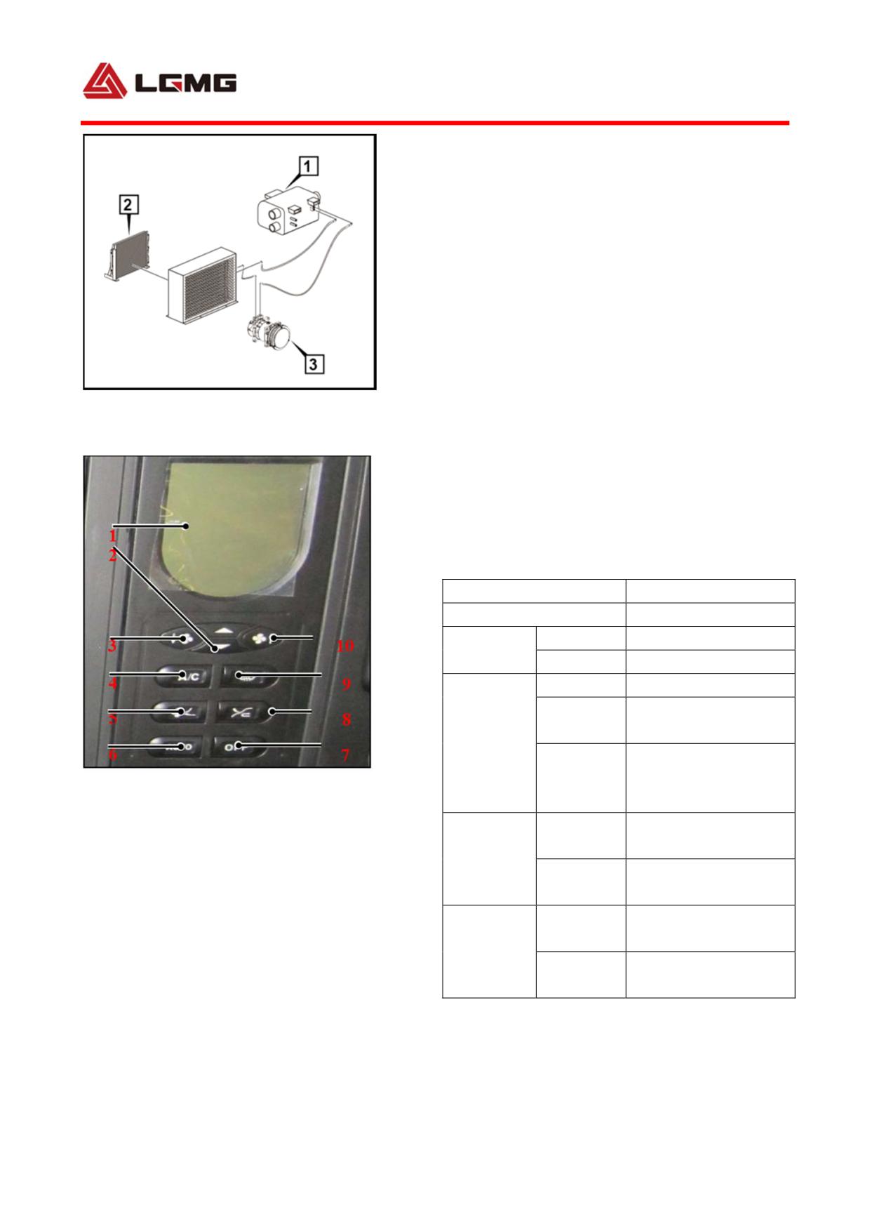
4.9 Operation and maintenance of A/C
4.9.1 General
The A/C system consists of radiator, compressor,
integrated condenser, evaporator and fan which are
connected as a closed system with pipes. The radiator
utilizes the engine circulating water as heat source,
the compressor is driven by the engine belt, the
power for fan and compressor magnetic clutch is
supplied by the vehicle, and the condenser is cooled
by water tank fan. The adopted refrigerant is R134a
Fig 4-43 The A/C system
which is of environment-friendly fluorine-free type.
1. evaporator 2. condenser 3. compressor
1) Control panel and display content (as shown left)
The air inlet modes are in a circulation of selection.
The air outlet and defrosting air outlet modes
selection are a circulation of head blow, feet blow,
feet blow & defrosting and defrosting.
2) Main technical parameters (see the table below):
Refrigerating capacity
4200W
Refrigerant
R134
Voltage
D.C 24V
Air output
138cc/r
Power
50W
Belt
GB2 A2,GB3 6PK
groove
Clutch
Pitch
GB2 170,GB3
diameter
125
Fig 4-44
of belt
1. Display
2. Temperature setting
Parallel flow
Core
3(10)Air-conditioning
4. Refrigeration
670×438×16mm
Condenser
5. Air outlet modes selection
6. Auto
7. OFF
Windward
0.29m2
8. Air inlet modes selection
area
9. Defrosting air outlet mode selection
Overlapped
Core
390×205×70mm
Evaporator
Windward
0.08m2
area
3) Description of air conditioning
refrigeration and heating principle
125
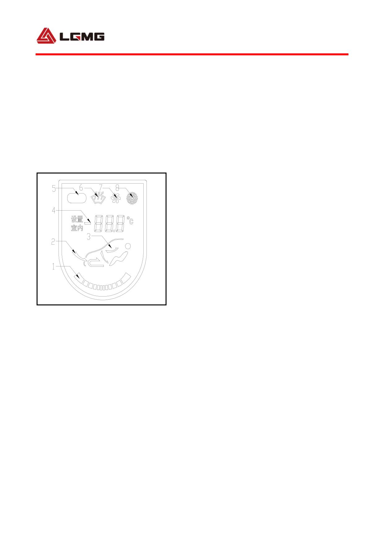
Refrigeration: after the refrigerant enters
the pipeline of the refrigeration system, it
is pressurized by the compressor into
refrigerant gas of high-temperature and
high-pressure, and then into liquid state
(actually a vapor-liquid mixture) after being
cooled through the condenser. The liquid
refrigerant is throttled by an expansion valve
in front of the evaporation tank, enters the
evaporation tank in the form of fog, absorbs
the surface temperature of the evaporator core
to make it cool. Heat exchange occurs when the
hot air sucked by the air blower passes through
the evaporation tank, it turns into cold air
and enters the cabin from the air outlet.
Heating: A heater box is arranged in the
Fig 4-45
evaporation tank, which is also referred to as
1. Air grade
2.Air inletwighar 6to
a heat exchanger and is directly connected with
3.Air outlet statewighar 6to wighar 6to
the engine water tank via a water pipe; the cold
4.Setting temperature and ambient temperature
air sucked by the blower turns into hot air when
5. AUTO
6.Defrosting
7. Blowing
passing through the surface of the heat
8.Refrigeration
exchanger by absorbing heat, and enters the
cab.
4.9.2 Operating instructions
1) Set your desirable inside temperature
Adjust the temperature setting key to set your
126
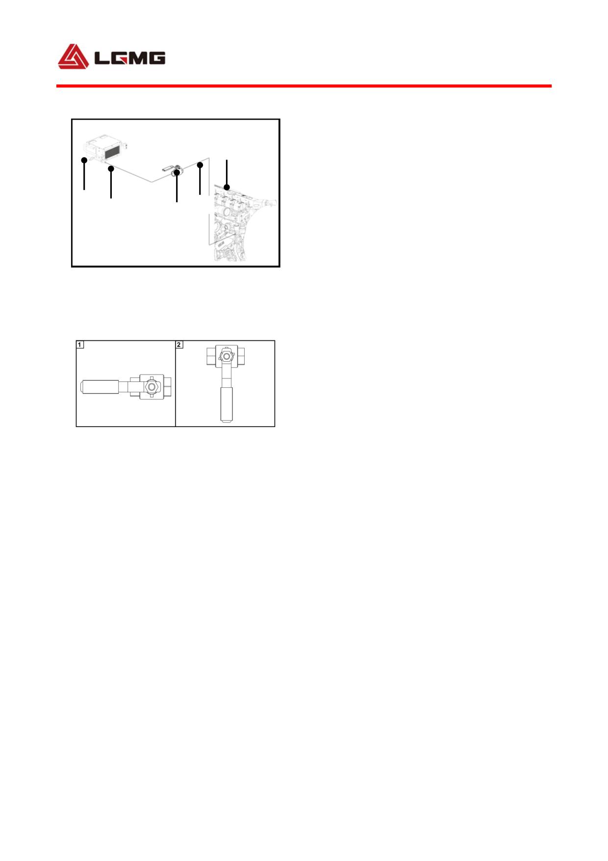
desirable inside temperature. Setting range:
LO, 18℃-29℃ and HI. Generally, temperature
5
set within 22℃-26℃ is appropriate. If you
want that it is cooler inside, set the
4
1
temperature at LO. If you want that it is warmer
2
3
inside, set the temperature at HI.
2) Set air volume
Fig 4-46
Generally, the system can adjust the air volume
1.Heater unit
2. Heater unit water inlet pipe
based on your setting temperature. You can also
3. Water valve
4. Engine heater unit water inlet pipe
5. Engine
manually set your desired air volume. Air
volume is classified into 9 classes. When you
press the air volume key, the air volume will
be adjusted gradually.
3) Use of hot air
Fig 4-47
1. Switch On Diagram 2. Switch Off Diagram
! Caution: Please turn off the heater
water valve switch before shut down the
heater unit!
When the temperature is too low, the
temperature of the cab can be increased by
using the hot air function.
The heater unit pipeline connection diagram is
shown in Figure 4-47.
As shown in Figure 4-48, turn on the heater
valve switch, and then the heater unit starts
operating. The temperature rise is controlled
by setting the air volume.
127
3) Night vision function
Switch on clearance lamp power, the key symbols
and other symbols are displayed synchronously.
4) Air outlet mode selection
By pressing the air outlet mode selection key
and defrosting selection key, 4 air outlet
modes can be selected, which are head blow,
feet blow, feet blow & defrosting and
defrosting.
5) Air inlet mode selection
In the following circumstances, internal
recirculation can be used for a short time:
● In hot weather, to quickly reduce the
inside temperature;
● In cold weather, to quickly increase the
inside temperature;
● The worse outside air quality, such as much
dirt and bad smell.
4.9.3 Precautions for operation
1) Regularly do maintenance for A/C system.
2) Wipe panel with a soft dry cloth. Wet cloth
or hard material is prone to damaging the panel,
keys or display screen.
3) Do not use finger, oily material or hard
object to contact display screen, otherwise it
may lead to illegible display, strokes missing
128
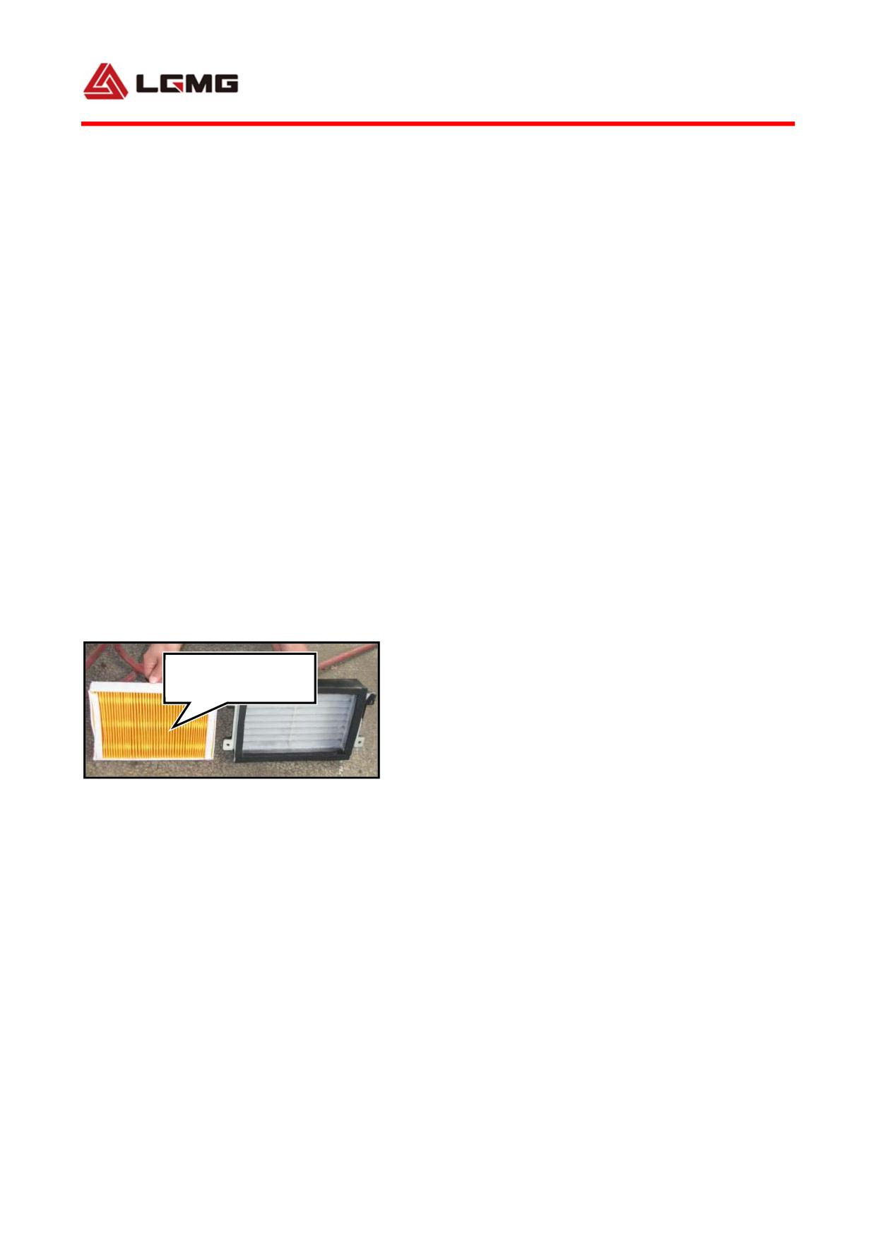
or display screen damage.
4) The refrigerant filler is on compressor and
pipes. In case of insufficient refrigerant or
poor refrigeration, please contact
professional personnel to supplement
refrigerant. When refrigerant is insufficient,
white foam can be seen through the observation
window on the upper part of pipe. When
refrigerant is sufficient, what you see is
transparent liquid.
5) When it is confirmed that a fault occurs in
the system, please go to an authorized service
station to have an inspection and repair by
professional service personnel.
6) The A/C intake paper filter core should be
Paper filter core
cleaned and replaced according to specific
operation conditions.
7) In the season that A/C is not used, start
Fig 4-48
the refrigeration system of A/C 2~3 times every
month, 10 min per time. The purpose is to
prevent poor sealing performance of rubber
seal ring and shaft seal of compressor in the
pipes of the system due to lack of oil. Poor
sealing performance will lead to compressor
and other movable components of refrigeration
system getting stuck or rusty.
129
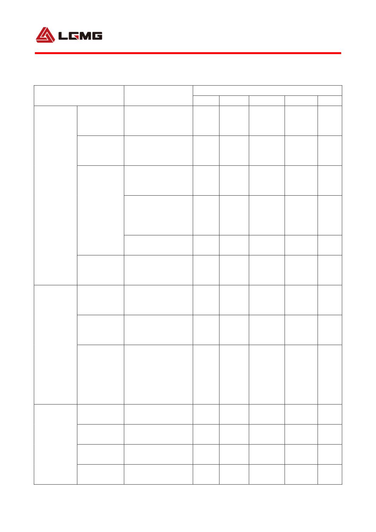
4.9.4 Service and maintenance
Maintenance interval
Maintenance items
Description
Weekly
Monthly
Bimonthly
Quarterly
Yearly
Check the amount of
Amount of
refrigerant through
+
refrigerant
observation window.
Check leakage with
Refrigerant
halogen leak
+
leakage
detector.
Check hose for
cracking and
+
damaging.
A/C unit
Check each joint for
Hose and
leakage and check
pipe
-
clamps for
looseness.
Change drying agent
-
and replace filter.
Change with
Refrigeration
corresponding grade
+
oil
refrigeration oil.
Check oil leakage
Shaft seal
mark with white
+
-
paper.
Tighten it with
Belt
tension pulley and
+
Compressor
check it for wear.
unit
Check bolts for
looseness. Do a fully
inspection and
Bolt overhaul
+
refitting, if
necessary.
Evaporator
Check it for dirt, and
+
core
clean it if necessary.
Check if it runs
Fan motor
+
Evaporator,
normally.
condenser
Condenser
Check it for dirt, and
+
core
clean it if necessary.
Check if it runs
Fan motor
+
normally.
130
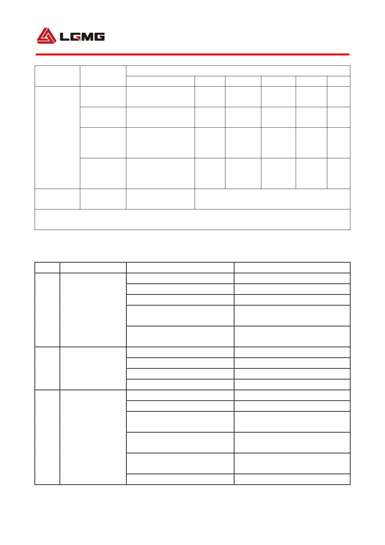
Maintenance
Maintenance interval
Description
items
Weekly
Monthly
Bimonthly
Quarterly
Yearly
Check clip plug for
Connector
+
+
looseness.
Thermistor
Check if it works
+
switch
normally.
Electrical
Check if it meets
Magnetic
element
specified
+
clutch
requirements.
Magnetic
Replace it if it
clutch
+
cannot rotate stably.
bearing
Paper filter
Clean or replace it according to specific
Intake filter
Check it for dirt.
element
conditions.
Note: “+” indicates that adjustment is required and do repair if necessary; “-” indicates that
replacement is required.
4.9.5 Fault diagnosis and troubleshooting list
S/N
Symptom
Probable causes
Solutions
System leaks.
Do leakage detection and repair.
Air return valve is closed.
Open it.
There is a lack of refrigerant.
Add refrigerant.
High pressure is
1
The air return valve of
low
Replace the valve.
compressor leaks.
The leaf valve of compressor is
Replace it.
damaged.
There is air in the system.
Refill the system with refrigerant.
High pressure is too
The condenser is blocked.
Clean the condenser.
2
high
The exhaust valve is closed.
Open it.
There is excessive refrigerant.
Discharge the extra.
There is a lack of refrigerant.
Add refrigerant.
The compressor piston is worn.
Repair it.
The compressor cylinder gasket
Replace the cylinder gasket.
leaks.
Low air return
3
The hose is twisted or squeezed
pressure
Replace the hose.
flat.
The air return valve of
Replace the valve plate.
compressor leaks.
There is moisture in the system.
Replace the air drier.
131
S/N
Symptom
Probable causes
Solutions
The sensing bulb of expansion
Tighten the sensing bulb clamp.
valve is loose.
High air return
There is excessive refrigerant.
Discharge the extra.
4
pressure
The compressor leaf is damaged.
Replace the leaf.
The compressor cylinder gasket
Replace the cylinder gasket.
leaks.
The drive belt is damaged.
Replace the belt.
The clutch conductor is
Replace the conductor.
damaged.
Compressor does
The compressor piston is
5
Replace the compressor.
not work.
damaged.
The thermostatic switch is in
Replace the thermostatic switch.
failure.
The clutch coil is damaged.
Replace the coil.
The coil is frozen; the set
Turn the thermostatic switch
temperature is too high.
downward to defrost it.
Close the door from which hot air
Hot air enters cab.
comes.
Poor refrigeration
There is a lack of refrigerant.
Add refrigerant.
6
effect
The high pressure is too high.
Refer to 2.
The return pressure is too low.
Refer to 3.
The return pressure is too high.
Refer to 4.
The thermostatic switch is in
Replace the thermostatic switch.
failure.
The adjustment of thermostatic
Adjust it to operating condition.
Evaporator coil gets
switch is inappropriate.
7
frozen.
The volume of air via evaporator
Check evaporator fan.
is insufficient.
The belt pulley is not properly
Adjust the axial position of belt
aligned.
pulley.
The belt is too tight or loose.
Adjust it correctly.
8
Belt is in failure.
The size and specification of belt
Replace it.
is incorrect.
The idler bearing is damaged.
Replace the bearing.
The fan Fuse is burnt out.
Replace it.
The control switch is in failure.
Replace it.
9
Fan does not work.
The fan motor is damaged.
Replace it.
The motor voltage is low.
Check conductor.
The fan is in poor contact.
Check and repair it.
132
S/N
Symptom
Probable causes
Solutions
The conductor is loose or in
Do troubleshooting.
short circuit.
The rotor shaft is bending.
Replace it.
10
Fan rotates slowly.
The controller resistor is burnt
Replace the resistor.
out.
The voltage is insufficient.
Check the alternator.
Check the fixing screw of blade.
Tighten the screw.
Joint leaks.
Repair or replace it.
11
Hose or joint leaks.
Hose leaks.
Replace the hose.
133
134
Chapter V Maintenance
135
136
5.1 Mileage for routine inspection & maintenance interval
Schedule of routine inspection & maintenance interval of mining dump truck
Maintenance
Initial
Routine
1st class
Routine
2nd class
Routine
3rd class
Routine
4th class
level
inspection
inspection
maintenance
inspection
maintenance
inspection
maintenance
inspection
maintenance
Engine
operating
30
50
100
300
500
800
1000
1200
1500
time (hours)
! CAUTION: Users should carry out the initial inspection immediately after
delivery of the truck provided that the engine has worked for 30 h or more on the
way of shipment.
5.2 Details on mandatory maintenance of MT86H mining off-highway off-highway
dump truck
Period
Material code
Material name
Specification
Unit
Qty
Remarks
100h(The
4110000001390
Oil filter
612630010239
Piece
2
actual work
5301000010
Diesel engine oil
CF-4 15W/40
L
27
ontime,dose
Fuel Coarse Filter
Weichai
4110001117322
1000424916
Piece
1
not include
Element
WD12.420
transit;time
4190002286
Fuel oil filter
1000442956
Piece
2
2,000 km)
4110000001390
Oil filter
612630010239
Piece
2
5301000010
Diesel engine oil
CF-4 15W/40
L
27
Weichai
Fuel Coarse Filter
4110001117322
1000424916
Piece
1
WD12.420
Element
4190002286
Fuel oil filter
1000442956
Piece
2
Air filter
4110001276
Air filter
1000267954
Piece
1
assembly
500h
5301000007
Gear oil
GL-5 85W-90
L
23
Transmission
(7000 km)
Return oil filter
4120001743
SJX-500×10
Piece
1
element
Lifting system
4120000634
Air filter element
SJXKL10×0.8-0.5
Piece
1
Center axle
unilateral
5301000007
Gear oil
SAE85W/90GL-5
L
45.6
wheel
reducer 6.3L
137
Period
Material code
Material name
Specification
Unit
Qty
Remarks
Rear axle
unilateral
wheel
500h
5301000007
Gear oil
SAE85W/90GL-5
L
36.6
reducer 6.3L
(7000 km)
Rear axle
main
drive:24L
4110000001390
Oil filter
612630010239
Piece
2
5301000010
Diesel engine oil
CF-4 15W/40
L
27
Weichai
Fuel Coarse Filter
1000h
4110001117322
1000424916
Piece
1
WD12.420
Element
(12000 km)
4190002286
Fuel oil filter
1000442956
Piece
2
Air filter
4110001276
Air filter
1000267954
Piece
1
assembly
4110000001390
Oil filter
612630010239
Piece
2
5301000010
Diesel engine oil
CF-4 15W/40
L
27
Weichai
Fuel Coarse Filter
4110001117322
1000424916
Piece
1
WD12.420
Element
4190002286
Fuel oil filter
1000442956
Piece
2
1500h
Air filter
(17000km)
4110001276
Air filter
1000267954
Piece
1
assembly
5301000010
Diesel engine oil
CF-4 15W/40
L
2.4
Balance shaft
Return oil filter
4120001743
SJX-500×10
Piece
1
element
Lifting system
4120000634
Air filter element
SJXKL10×0.8-0.5
Piece
1
! Note:
1. If it is reached mandatory service requirements before delivery the customer, the
service can be performed at the destination.
2. The grade of the hydraulic oil filled at the factory is L-HM32, which can be changed
to L-HM46 hydraulic oil by users.
138
! CAUTION:
● The oil acts as the primary medium to absorb the dust and other particles when
the oil-bath is working, so the clean waste engine oil or gear oil can be applied.
● Two brands of hydraulic oil can be switched, but must not be mixed!
● Please select the conformed lubricating oil according to the specific ambient
temperature.
● Users should take all consequences caused by the use of the oil products for
maintenance that are not specified by our company.
5.3 Key points of maintenance
5.3.1 Routine maintenance items
1) Check the hand brake and the foot brake.
2) Check working conditions of the illumination system, instrument signal system and various indicators (oil
pressure, air reservoir pressure, air filter maintenance indicator and charge indicator).
3) Check working conditions of the starter and the generator as well as the battery electrolyte level.
4) Check the air pressure and state of tires.
5) Check liquid levels of the engine oil, coolant and traversing mechanism hydraulic oil.
6) Discharge water from the air reservoir.
5.3.2 Cleaning and inspection of transmission system parts
1) Cleaning
The parts surface of each assembly of transmission system might be stuck with dirty oil and sludge,
so cleaning parts is indispensable. The common methods are cleanings with steam, gas, acid
solution or alkaline solution, neutral agent and trichloroethylene as well as magnetic cleaning. In
this process, damage to some parts might occur. Therefore, careful inspection must be done in the
process of cleaning.
a. Metal parts
● Cleaning with gas. Unlike other methods, gas can hardly infiltrate or dissolve sludge. Unless
the surface of parts is precisely refined, wire brush or other tools can be used to clean sludge for
twice.
● Alkalization treatment. If parts are made of alloys, they cannot adopt this treatment. The
alkalization treatment used to clean steel castings and iron castings has better effect.
b. Rubber parts
139
No mineral oil can be used. Use alcohol or one piece of clean cloth to wipe impurities.
c. Rust protection
After cleaning all the waste oil and grease on the part surface, smear one layer of clean oil on the
surface to prevent rust.
2) Inspection
Before cleaning parts, use prepared measuring instrument or tools to inspect. Determine whether
the parts are suitable for reuse according to specified maintenance standards. Damaged parts
require maintenance or replacement. If one piece of matched part is severely damaged, and its
assembly clearance exceeds the prescribed limits, replace this part or the matched part as
required.
In the perspective of preventive maintenance, some parts under repair or within wear limits
should be replaced before they exceed the limits.
All the parts should be carefully inspected by visual observation or infrared inspection. If the
following anomalies are found by visual observation, this part can be repaired or replaced as
required.
! Caution: For all the seal rings, such as O-shape ring, oil seal, seal washer,
once dismounted, they are required to be replaced, and should not be reused.
5.3.2 See the following table for all levels of maintenance items:
Maintenance level
Item
Description
Initial
Routine
1st class
2nd
3rd
4th class
inspection
inspection
maintenance
classmaintenance
classmaintenance
maintenance
Change engine oil
●
●
●
●
Replace oil filter
Whenever replacing the engine oil
Check and adjust
●
●
●
●
●
valve clearances
Replace fuel filter
●
●
●
●
element
Clean or replace
Engine
filter element of
●
●
●
●
coarse fuel filter
Check coolant
volume and add
●
●
●
●
●
●
when necessary
Change coolant
Once every six months
Tighten cooling
●
●
pipeline clamps
140
Maintenance level
Item
Description
Initial
Routine
1st class
2nd
3rd
4th class
inspection
inspection
maintenance
classmaintenance
classmaintenance
maintenance
Tighten air intake
pipeline hoses
●
●
●
●
●
●
and flange
connecting pieces
Check air filter
maintenance
●
●
●
●
●
indicators
Clean
dust-collecting
●
●
●
●
●
cup of air filter
Clean main filter
element of air
Once every 250 hours
Engine
filter
Replace safety
filter element of
Whenever replacing the main filter element
air filter
Check
supercharger
●
bearing clearance
Wire harnesses of
electrical
components and
Once at the interval of 250 hours
electrically
controlled system
Check oil level of
●
●
Transmission
Replace
transmission
Transmission
●
lubricating oil (at
least every year)
Replace air
●
●
●
breather
141
Maintenance level
Item
Description
Initial
Routine
1st class
2nd
3rd
4th class
inspection
inspection
maintenance
classmaintenance
classmaintenance
maintenance
Check and adjust
clearances of
taper roller
Whenever doing the 1st class inspection and the 2nd class maintenance
Front axle
bearing for wheel
hub
Replace grease
●
●
for wheel hub
Check oil levels of
main reducer and
●
●
wheel reducer
Check bogie
Whenever doing the 1st class inspection and the 2nd class maintenance
differential
Center axle
Replace
lubricating oil for
main reducer and
●
wheel reducer (at
least every year)
Check oil levels of
main reducer and
●
●
wheel reducer
Replace
lubricating oil for
main reducer and
●
wheel reducer (at
least every year)
Rear axle
Clean air
●
●
●
●
breathers
Check and adjust
clearances of
taper roller
Whenever doing the 1st class inspection and the 2nd class maintenance
bearing for wheel
hub
142
Maintenance level
Item
Description
Initial
Routine
1st class
2nd
3rd
4th class
inspection
inspection
maintenance
classmaintenance
classmaintenance
maintenance
Re-tighten
propeller shaft
Once every 100 hours
bolts
Propeller
Visually inspect
shaft
connection and
Once every 100 hours
wearing of
propeller shafts
Check actions of
●
●
●
●
●
●
wiper
Re-tighten
locking handle of
●
●
●
●
cab
Re-tighten heat
Cab
dissipation shield
●
●
●
●
●
of engine
Check oil level of
cab tilting manual
●
●
●
●
oil pump
Check adjustment
●
●
●
●
●
●
of lifting cylinder
Check fixation of
●
●
●
●
●
●
towing hook
Re-tighten
●
crossbeam bolts
Tighten U-bolts
and brackets of
●
●
●
●
front/rear leaf
springs
Chassis
Check and adjust
clearance of
●
●
●
●
baffles of leaf
spring side
Check fixation of
●
●
●
●
●
●
wheel nuts
Check fixation of
●
●
●
●
batteries
143
Maintenance level
Item
Description
Initial
Routine
1st class
2nd
3rd
4th class
inspection
inspection
maintenance
classmaintenance
classmaintenance
maintenance
Check fixation of
Chassis
●
●
●
●
fuel tanks
Drain air
●
●
●
●
●
●
reservoir
Check tightness
of air pressure
●
●
●
●
●
system (via
barometer)
Check thickness
of friction lining
and adjust
●
●
●
●
clearance of
brake
Clean wheel
●
●
●
brake
Brake system
Check positions
of brake pipelines
and hoses that
●
●
●
●
●
can be easily
scratched.
Check functions
●
●
●
●
●
of brake chamber
Check
performance of
foot brake, hand
brake and
●
●
●
●
●
●
exhaust brake
(during
commissioning)
144
Maintenance level
Item
Description
Initial
Routine
1st class
2nd
3rd
4th class
inspection
inspection
maintenance
classmaintenance
classmaintenance
maintenance
Check retarder
system, in which
indicator shall
operate properly,
connecting pieces
Check before each trip
are connected
firmly, and
appearance is
clean
Check clearance
between retarder
Once every months
Brake system
rotor and stator
Check retarder oil
seal, bearing
lubrication status,
manual switch
Once every months
function, relay
wiring and
contact status
Check axial
movement
Once every months
clearance of
retarder
Check working
conditions of
electrical system
(signal lamp,
●
●
●
●
●
●
headlamp, height
lamp, wiper,
HVAC and air
Electrical
breather)
system
Check liquid level
and gravity of
battery
electrolyte as
●
●
●
●
●
well as voltages
of each battery
unit
145
Maintenance level
Item
Description
Routine
1st class
2nd
3rd
4th class
Initial inspection
inspection
maintenance
classmaintenance
classmaintenance
maintenance
Check fixation of
battery wiring
terminals and
●
●
●
●
●
apply grease to
Electrical
electrodes
system
Check
correctness of
speed displayed
●
●
●
●
●
●
in electronic
tachometer
Replace steering
(20000~25000km)
oil
Check and
adjust front
●
●
wheel
alignment
Check functions
Steering
of steering
●
●
system
system
Check clearance
●
●
●
●
of steering lever
Check bolts,
joints and
●
●
locking pieces of
steering levers
Check for wear
Once every day
of oil pipe
Check oil level in
hydraulic oil
Once every day
tank and level
meter
Lifting
Check for
system
looseness of oil
cylinder bracket
and top big nut,
Once every day
and clearance of
oil cylinder
bracket
146
Maintenance level
Item
Description
Routine
1st class
2nd
3rd
4th class
Initial inspection
inspection
maintenance
classmaintenance
classmaintenance
maintenance
Check for
inclination of oil
cylinder when
Once every day
lifting it without
load
Check for
looseness of
bracket bolts of
Once every week
oil tank and oil
pump
Check if limit
Lifting
valve operates
Once every week
system
properly
Replace oil
return filter
Once every six months
element and air
filter element
Check lifting
●
●
●
●
●
angle
Check tightness
●
●
●
●
●
of gas circuit
Check hydraulic
Once every six months
oil
Short-distance
commissioning
●
●
●
●
●
(include brake
test)
Complete
truck
Visually inspect
●
●
●
●
●
●
leakage
Check fixation of
carriages and
●
●
●
●
●
●
tighten them
when necessary
Water pump
●
●
●
●
●
●
Lubrication
Clutch pedal
●
●
●
●
●
●
shaft
147
Maintenance level
Item
Description
Routine
1st class
2nd
3rd
4th class
Initial inspection
inspection
maintenance
classmaintenance
classmaintenance
maintenance
Clutch release
●
●
●
●
●
●
bearing
Clutch fork shaft
●
●
●
●
●
●
Universal joint
●
●
●
●
●
●
Steering
kingpin, front
●
●
●
●
●
axle
Leaf spring pin
Once every 10 hours
Inspection of
clearance of
baffles at
Once every 10 hours
balance
Lubrication
suspension leaf
spring side
Lower bracket
of shock
●
●
●
●
●
●
absorber
Transmission
●
●
●
●
●
manipulator
Brake camshaft
●
●
●
●
●
●
and brake arm
Towing hook
●
●
●
●
●
●
Door hinge of
●
●
●
●
●
●
cab
Re-treat the cab
against rust as
Once at the interval of 12 months
planned
148
5.3.3 Selection of oil products
Recommended types and
Type
Amount
Part
standards
Ambient temp.≥-15° CF-4 15W/40
Engine oil
27L
Weichai engine
Ambient temp.<-15°CF-4 15W/40
Heavy-duty vehicle gear oil (GL-5)
Central axle: 45.6L
85W-90
Rear axle: 36.6L
Axle main drive, bogie
Gear oil
Ambient temp.≥-15° Heavy-duty
differential housing, final
vehicle gear oil (GL-5) 85W-140
drive and transmission
Transmission:23L
Ambient temp.≥-26° Heavy-duty
vehicle gear oil (GL-5) 80W-140
L-HM46 hydraulic oil GB11118.1
Hydraulic
135L
Hydraulic oil tank
L-HM32 hydraulic oil GB11118.1
oil
L-HV32 hydraulic oil GB11118.1
0.5L
Cab tilting system
Ambient temp.≥4°C 0# light diesel
GB252
Ambient temp.≥-5°C -10# light
diesel GB252
Fuel
530L
Fuel tank
Ambient temp.≥-14° -20# light
diesel GB252
Ambient temp.≥-29°C -35# light
diesel GB252
Vehicle brake liquid HZY3 (DOT3)
Brake fluid
1.5L
Brake system
GB12981
Pin shaft at each hinged
Grease
2# or 3# lithium grease GB7324
point of working device
Antifreeze
Antifreeze fluid -35#
50L
Radiator system
fluid
149
5.3.4 Reference table of oil products in China and abroad
1) Engine oil
Grade of
Grade of similar foreign brand oil (ranked as per US SAE)
domestic oil
CALTEX
SHELL
MOBIL
ESSO
Diesel engine oil
RotellaSX 40;
MobilDelvacSuper 130
Essolube XT-3;
CD or higher
Rotella TX 40, 20W/40;
(SAE15W-40) (-15°C~
CALTEX Delo
Essolube XT-2
15W-40 GB11122
Rotella DX 40
50°C)
Gold
MobilDelvacSuper 130
Diesel engine oil
Multigrade
Rotella SX30, 10W/30;
(SAE10W-30)
CD or higher
15W-40
Rotella TX30;
Essolube XT-5
(-20°C-40°C); Delvac 1#
5W-30 GB11122
Rotella DX30
(-40°C or higher)
2) Hydraulic oil
Grade of
Grade of similar foreign brand oil
domestic oil
CALTEX
MOBIL
SHELL
CASTROL
ESSO
Hydraulic oil
RANDO OIL
L-HM46
DTE 24
Tellus 32
Hyspin ZZ 32
Nuto H 32
HD32 RANDO
Hydraulic oil
DTE 25
Tellus 46
Hyspin ZZ 46
Nuto H 46
OIL HD46
L-HM32
3) Gear oil (drive axle oil)
Grade of domestic
Grade of similar foreign brand oil (ranked as per US API, GL-5)
oil
CALTEX
FUCHS
MOBIL
ESSO
SHELL
CALTEX
Heavy-duty
Mobil gear
Spirax EP
Super extreme
Gear oil
vehicle gear oil
Titan Gear
HD80W-90(-20°C-40°C)
Heavyduty
pressure gear oil
GX
(GL-5) 85W-90
LS90
HD85W-90
HD90
90 Thuban GL5
85W-90
GB13895
(-10°C-50°C)
HD80W-90
EP 90
4) Brake liquid
Grade of similar foreign brand oil
Grade of domestic oil
Grade
MOBIL
ESSO
BP
SHELL
Vehicle brake liquid
Super brake
Brake Fluid
SAE
HZY3
liquid
Brake Fluid
Disc-Brake
Donax B
1703C
GB12981
DOT3
fluid
150
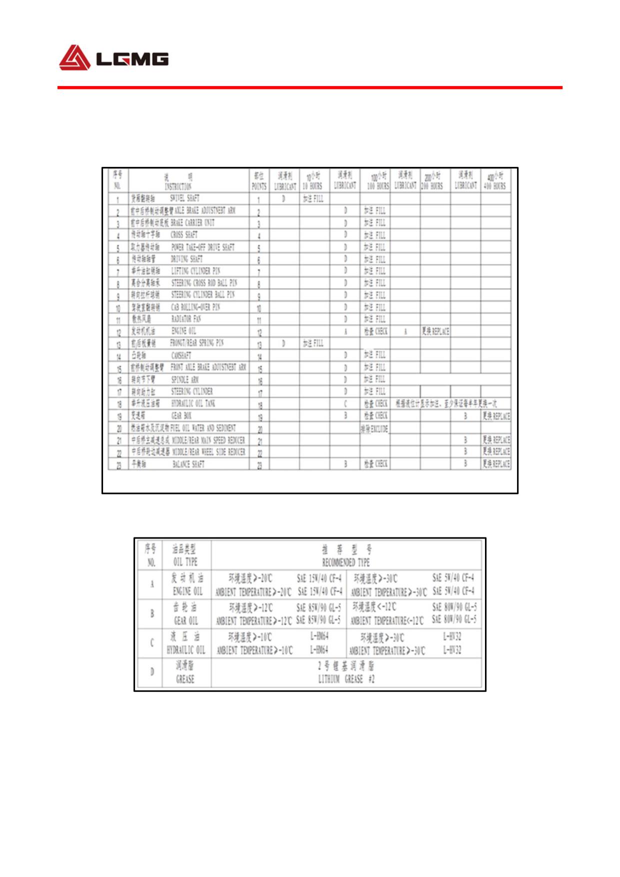
5.4 Lubrication of chassis
1. Lubrication requirements
Note: The contents shown in this lubrication scutcheon are the data under normal working conditions and temperature.
Customers can make adjustments according to difference of working conditions and temperatures.
2. List of categories of lubricant
151
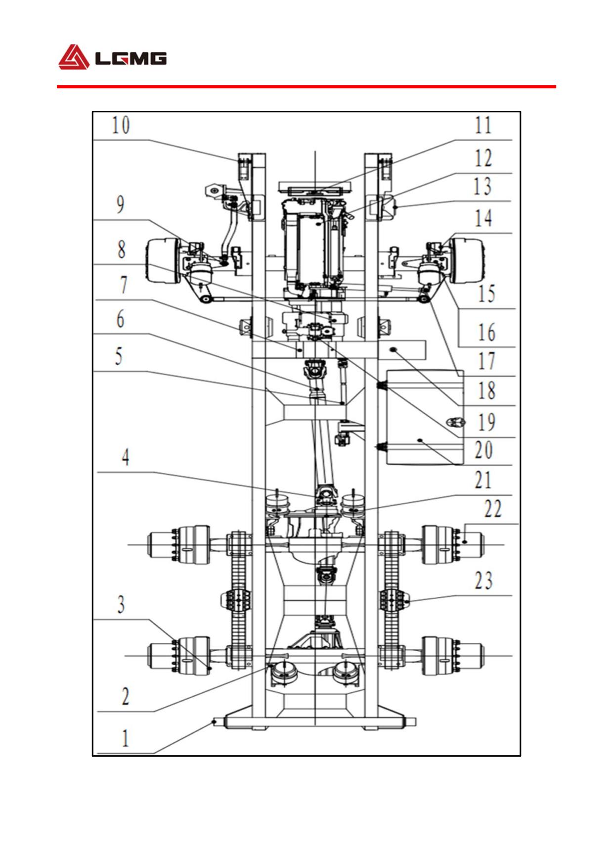
3. Lubrication diagram
152
Chapter VI Annex
153
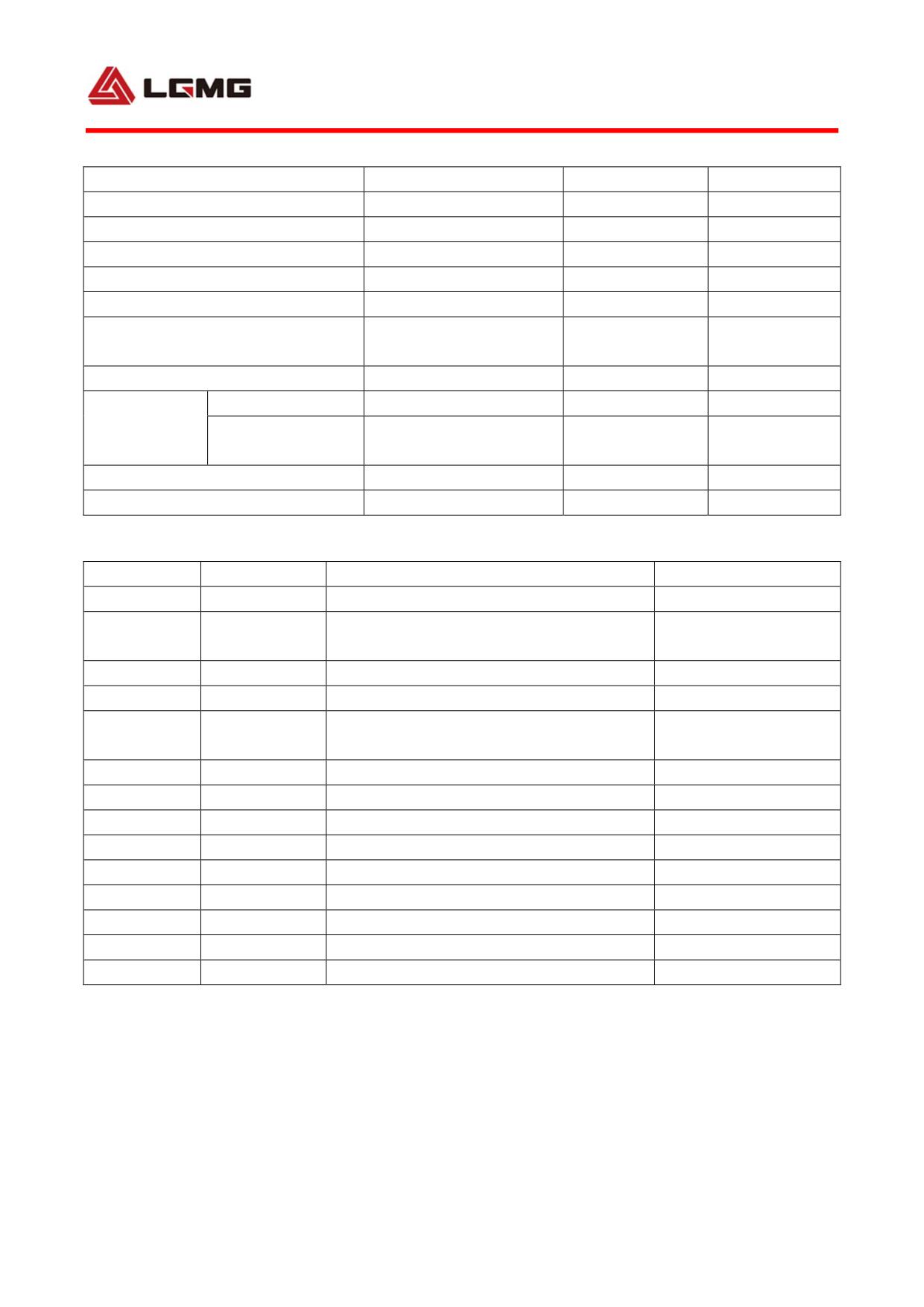
6.1 List of bulbs
Name
Type
Power
Qty.
Headlamp (high/low)
H4
24V70W/75W
70W/75W
2
Front fog lamp
H3
24V70W
70W
2
Side turn signal lamp
24V1W
1W
2
Front turn signal lamp
24V1W
1W
2
Height lamp
24V0.4W
0.4W
3
Front working lamp and rear
B3H3
24V70W
70W
3
working lamp of cab
Side working lamps
LED 24V3W
12W
2
Rear
Turn signal lamp
24V 1W
1W
2
combination
Brake lamp/tail
24V 1W/0.2W
1W/0.2W
2
lamp
lamp
Reversing lamp
LED 24V3W
27W
2
Indoor illumination lamp
24V10W
10W
1
6.2 List of quick-wear parts of electrical system
No.
Code
Name
Qty.
1
4130000007
Pressure switch YK-M10×1-0.3MPa-K↑
1
Pressure switch
2
4130000006
1
YK-M12×1.5-0.55MPa-B↓
3
4130000250
Head lamp (right)
1
4
4130000249
Head lamp (left)
1
ELECTRICAL PRESSURE SENSOR
5
4130000420
2
LG9130773001
6
4130000309
Ignition lock assembly - LG751
1
7
4130000308
Combination switch
1
8
4130000592
Electronic mileage sensor C03054-16
1
9
4130000003
Oil pressure sensor
1
10
4130000375
Fuse ATS-5A
1
11
4130000376
Fuse ATS-10A
1
12
4130000377
Fuse ATS-15A
1
13
4130000378
Fuse ATS-20A
1
14
4130000492
Brake light switch YK209KLA
1
154
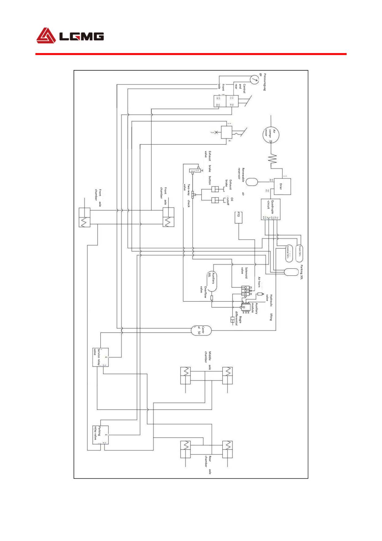
6.3 Schematic diagram of brake
155
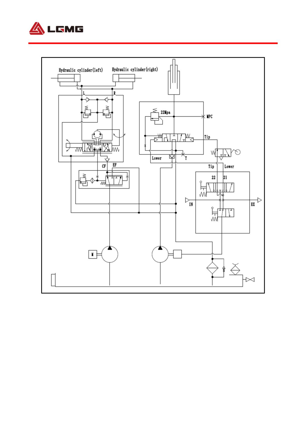
6.4 Principle of hydraulic system
Engine
Take power
device
156