Parker 514C DC Controller. Product Manual (2007)
514C
DC Controller
Product Manual
HA463296 Issue 6
WARRANTY
Parker SSD Drives warrants the goods against defects in design, materials and workmanship for the period of 12 months from the date of delivery on the
terms detailed in Parker SSD Drives Standard Conditions of Sale IA058393C.
Parker SSD Drives reserves the right to change the content and product specification without notice.
Cont.2
Requirements
IMPORTANT: Please read this information BEFORE installing the equipment.
Intended Users
This manual is to be made available to all persons who are required to install, configure or service equipment
described herein, or any other associated operation.
The information given is intended to highlight safety issues, EMC considerations, and to enable the user to obtain
maximum benefit from the equipment.
Complete the following table for future reference detailing how the unit is to be installed and used.
INSTALLATION DETAILS
Serial Number
(see product label)
Where installed
(for your own
information)
Unit used as a:
R Component
R Relevant Apparatus
(refer to Certification
for the Inverter)
Unit fitted:
R Wall-mounted
R Enclosure
Application Area
The equipment described is intended for industrial motor speed control utilising AC induction or AC synchronous
machines.
Personnel
Installation, operation and maintenance of the equipment should be carried out by qualified personnel. A qualified
person is someone who is technically competent and familiar with all safety information and established safety
practices; with the installation process, operation and maintenance of this equipment; and with all the hazards
involved.
Product Warnings
Earth/Ground
Caution
Caution
Protective
Risk of electric
Refer to
Conductor
shock
documentation
Terminal
Cont.3

Hazards
DANGER! - Ignoring the following may result in injury
1. This equipment can endanger life by exposure to
5. For measurements use only a meter to IEC 61010 (CAT
rotating machinery and high voltages.
III or higher). Always begin using the highest range.
CAT I and CAT II meters must not be used on this
2. The equipment must be permanently earthed due to
product.
the high earth leakage current, and the drive motor
6. Allow at least 5 minutes for the drive's capacitors to
must be connected to an appropriate safety earth.
discharge to safe voltage levels (<50V). Use the
specified meter capable of measuring up to 1000V dc &
3. Ensure all incoming supplies are isolated before
ac rms to confirm that less than 50V is present between
working on the equipment. Be aware that there may
all power terminals and earth.
be more than one supply connection to the drive.
7. Unless otherwise stated, this product must NOT be
4. There may still be dangerous voltages present at
dismantled. In the event of a fault the drive must be
power terminals (motor output, supply input phases,
returned. Refer to "Routine Maintenance and Repair".
DC bus and the brake, where fitted) when the motor
is at standstill or is stopped.
WARNING! - Ignoring the following may result in injury or damage to equipment
SAFETY
Where there is conflict between EMC and Safety requirements, personnel safety shall always take precedence.
• Never perform high voltage resistance checks on the
• All control and signal terminals are SELV, i.e. protected
wiring without first disconnecting the drive from the
by double insulation. Ensure all external wiring is rated
circuit being tested.
for the highest system voltage.
• Whilst ensuring ventilation is sufficient, provide
• Thermal sensors contained within the motor must have
guarding and /or additional safety systems to
at least basic insulation.
prevent injury or damage to equipment.
• All exposed metalwork in the Inverter is protected by
• When replacing a drive in an application and before
basic insulation and bonded to a safety earth.
returning to use, it is essential that all user defined
• RCDs are not recommended for use with this product
parameters for the product’s operation are correctly
but, where their use is mandatory, only Type B RCDs
installed.
should be used.
EMC
• In a domestic environment this product may cause
• This is a product of the restricted sales distribution class
radio interference in which case supplementary
according to IEC 61800-3. It is designated as
mitigation measures may be required.
“professional equipment” as defined in EN61000-3-2.
Permission of the supply authority shall be obtained
• This equipment contains electrostatic discharge
before connection to the low voltage supply.
(ESD) sensitive parts. Observe static control
precautions when handling, installing and servicing
this product.
CAUTION!
APPLICATION RISK
• The specifications, processes and circuitry described herein are for guidance only and may need to be adapted to the
user’s specific application. We can not guarantee the suitability of the equipment described in this Manual for
individual applications.
RISK ASSESSMENT
Under fault conditions, power loss or unintended operating conditions, the drive may not operate as intended.
In particular:
• Stored energy might not discharge to safe levels
• The motor's direction of rotation might not be controlled
as quickly as suggested, and can still be present
• The motor speed might not be controlled
even though the drive appears to be switched off
• The motor might be energised
A drive is a component within a drive system that may influence its operation or effects under a fault condition.
Consideration must be given to:
• Stored energy
• Supply disconnects
• Sequencing logic
• Unintended operation
Cont.4
514C
Contents
Chapter 1 Product Overview
1
Description
1
Product Range
1
540 TO 514C upgrade
1
European Directives and the CE Mark
1
Certificates
6
Product Identification
7
Technical Specification
8
Environmental Requirements
10
EMC Technical Ratings
11
Product Code
11
Chapter 2 Pre-Installation Planning
2-1
Basic Wiring Diagrams
2-1
Terminal Descriptions
2-2
Terminal Comparison 540/1 to 514C
2-4
Block Diagram
2-1
Functional Differences 514C - 540
2-2
Chapter 3 Installation Procedure
3-1
Installation Precautions
3-1
Mechanical Installation
3-1
Electrical Installation
3-3
Requirements for UL Compliance
3-5
Chapter 4 Setting-Up & Commissioning
4-1
Option Switches
4-1
Potentiometers
4-2
Basic Setting-up Procedure
4-3
Running Performance Adjustments
4-7
Chapter 5 Diagnostics and Fault Finding
5-1
Diagnostic Leds
5-1
Drive Trips
5-2
Diagnostic Test Point Descriptions
5-2
Troubleshooting
5-4
Chapter 6 Service and Repair
6-1
DISPOSAL
6-1
Cont.5
Product Overview
1-1
Chapter 1 Product Overview
DESCRIPTION
The 514C controller is intended for use in an Industrial Environment, it should be mounted
within an enclosure which provides protection to the controller and the user.
The controller should be permanently earthed at the terminals provided.
The 514C controller is designed to control the speed of a DC Shunt wound or permanent
magnet motor. It will provide control of the motor speed in all 4 Quadrants of operation.
The controllers are designed to operate from a single phase AC mains supply in the range of
110 Vac to 415 Vac at 50 or 60 Hz. An auxiliary supply is required for internal power supply
generation and main supply contactor sequencing. Coding is derived from the main power
terminals and is functional over the whole input voltage range.
The Speed of the DC Motor is controlled using a linear closed loop system with a feedback
signal from either tachogenerator or armature voltage, the feedback source being switch
selectable.
A current loop within the speed loop always ensures that controlled levels of current are
applied to the motor, actual levels being scaleable via programmable switches.
Motor protection is provided by a Stall detection circuit which will remove current from the
motor after approximately 60 seconds.
Controller protection is provided by a Instantaneous Overcurrent trip circuit overriding
control in the event of a Short Circuit.
PRODUCT RANGE
Product
Rating
514C/04
4A DC Full Load Current
514C/08
8A DC Full Load Current
514C/16
16A DC Full Load Current
514C/32
32A DC Full Load Current
540 TO 514C UPGRADE
The 514C is designed to be functionally equivalent to the 540 series controllers not a direct
replacement. Comparisons between the two controllers connectors are included throughout
the manual.
Chapter 2 describes the terminal connectors to the 514C controller, in that section on page 2.4
is given a terminal to terminal comparison of 540/1 to 514C.
EUROPEAN DIRECTIVES AND THE CE MARK
The following information is supplied to provide a basic understanding of the EMC and low
voltage directives CE marking requirements. The following literature is recommended for
further information:
• Recommendations for Application of Power Drive Systems (PDS), European Council
Directives - CE Marking and Technical Standardisation - (CEMEP)
Available from your local trade association or Parker SSD Drives office
514C Product Manual
1-2 Product Overview
• EMC Installation Guidelines for Modules and Systems - (SSD Drives)
Available from your local Parker SSD Drives office, part number HA388879
• Short Form Overview of European Directives for Variable Speed Drives and
Applications - (SSD Drives)
Available from your local Parker SSD Drives office, part number HA389770
The European machines and drives manufacturers via their national trade associations have
formed the European Committee of Manufacturers of Electrical Machines and Power
Electronics (CEMEP). Parker SSD Drives and other major European drives manufacturers are
working to the CEMEP recommendations on CE marking. The CE mark shows that a product
complies with the relevant EU directives, in our case the Low Voltage Directive and, in some
instances, the EMC Directive.
CE Marking for Low Voltage Directive
When installed in accordance with this manual, the 590 Series Converter is CE marked by
Parker SSD Drives Ltd in accordance with the low voltage directive (S.I. No. 3260
implements this LVD directive into UK law). An EC Declaration of Conformity (low voltage
directive) is included at the end of this chapter.
CE Marking for EMC - Who is Responsible?
NOTE: THE SPECIFIED EMC EMISSION AND IMMUNITY PERFORMANCE OF THIS UNIT
CAN ONLY BE ACHIEVED WHEN THE UNIT IS INSTALLED TO THE EMC
INSTALLATION INSTRUCTIONS GIVEN IN THIS MANUAL.
According to S.I. No. 2373 which implements the EMC directive into UK law, the
requirement for CE marking this unit falls into two categories:
1. Where the supplied unit has an intrinsic/direct function to the end user, then the unit is
classed as relevant apparatus.
2. Where the supplied unit is incorporated into a higher system/apparatus or machine which
includes (at least) the motor, cable and a driven load but is unable to function without this
unit, then the unit is classed as a component.
Q Relevant Apparatus - Parker SSD Drives Responsibility
Occasionally, say in a case where an existing fixed speed motor - such as a fan or pump - is
converted to variable speed with an add-on drive module (relevant apparatus), it becomes the
responsibility of Parker SSD Drives to apply the CE mark and issue an EC Declaration of
Conformity for the EMC Directive. This declaration and the CE mark is included at the end of
this chapter.
Q Component - Customer Responsibility
The majority of Parker SSD Drives’ products are classed as components and therefore we
cannot apply the CE mark or produce an EC Declaration of Conformity in respect of EMC. It
is therefore the manufacturer/supplier/installer of the higher system/apparatus or machine
who must conform to the EMC directive and CE mark.
Legal Requirements for CE Marking
IMPORTANT: Before installation, clearly understand who is responsible for conformance with the
EMC directive. Misappropriation of the CE mark is a criminal offence.
It is important that you have now defined who is responsible for conforming to the EMC
directive, either:
514C Product Manual
Product Overview
1-3
Q Parker SSD Drives Responsibility
You intend to use the unit as relevant apparatus.
When the specified EMC filter is correctly fitted to the unit following EMC installation
instructions, it complies with the relevant standards indicated in the following tables. The
fitting of the filter is mandatory for the CE marking of this unit to apply.
The relevant declarations are to be found at the end of this chapter. The CE mark is displayed
on the EC Declaration of Conformity (EMC Directive) provided at the end of this chapter.
Q Customer Responsibility
You intend to use the unit as a component, therefore you have a choice:
1. To fit the specified filter following EMC installation instructions, which may help you
gain EMC compliance for the final machine/system.
2. Not to fit the specified filter, but use a combination of global or local filtering and
screening methods, natural migration through distance, or the use of distributed parasitic
elements of the existing installation.
NOTE: WHEN TWO OR MORE EMC COMPLIANT COMPONENTS ARE COMBINED TO
FORM THE FINAL MACHINE/SYSTEM, THE RESULTING MACHINE/SYSTEM MAY
NO LONGER BE COMPLIANT, (EMISSIONS TEND TO BE ADDITIVE, IMMUNITY IS
DETERMINED BY THE LEAST IMMUNE COMPONENT). UNDERSTAND THE EMC
ENVIRONMENT AND APPLICABLE STANDARDS TO KEEP ADDITIONAL
COMPLIANCE COSTS TO A MINIMUM.
Applying for CE Marking for EMC
We have supplied a Manufacturer’s EMC Declaration at the end of this chapter that you can
use as a basis for your own justification of overall compliance with the EMC directive. There
are three methods of demonstrating conformity:
1. Self-certification to a relevant standard
2. Third party testing to a relevant standard
3. Writing a technical construction file stating the technical rationale as to why your final
machine/system is compliant. An EMC “competent body” must then assess this and issue
a technical report or certificate to demonstrate compliance.
Refer to Article 10(2) of Directive 89/336/EEC.
With EMC compliance, an EC Declaration of Conformity and the CE mark will be issued for
your final machine/system.
IMPORTANT: Professional end users with EMC expertise who are using drive modules and cubicle
systems defined as components who supply, place on the market or install the
relevant apparatus must take responsibility for demonstrating EMC conformance
and applying the CE mark and issuing an EC Declaration of Conformity.
514C Product Manual
1-4 Product Overview
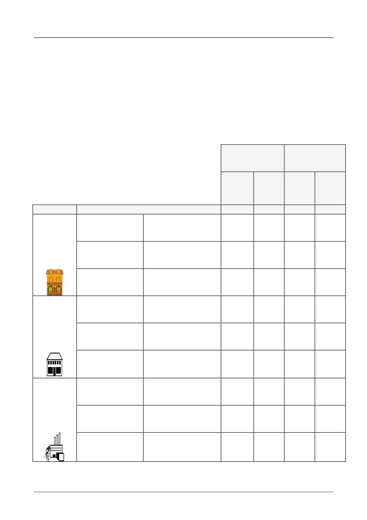
Which Standards Apply?
Basic and Generic Standards
The standards that may apply to this unit come under two broad categories:
1. Emission - these standards limit the interference caused by operating
(this) drive module.
2. Immunity - these standards limit the effect of interference (on this unit)
from other electrical and electronic apparatus.
The following table indicates the standards that the unit may comply with, dependent upon
how it is installed and used.
Unit used as
Unit used as a
Relevant
Component
Apparatus
Assuming installation to EMC instructions in this manual
filter
no filter
filter
no filter
(EMC
(EMC
“Filter” refers to a specified external filter.
compliance)
compliance
may be
applied for)
Installation
Basic and Generic Standards
enclosure
enclosure
enclosure
enclosure
Radiated RF
EN55022 Class B
Emission
(1994) or
EN50081-1 (1992)
Residential
Conducted RF
EN55022 Class B
Emission
(1994) or
EN50081-1 (1992)
Immunity
EN50082-1 (1992)
Radiated RF
EN55022 Class B
Emission
(1994) or
EN50081-1 (1992)
Commercia
Conducted RF
EN55022 Class B
l & Light
Emission
(1994) or
Industry
EN50081-1 (1992)
Immunity
EN50082-1 (1992)
Radiated RF
EN55011 Class A
Emission
(1991)
or
EN50081-2 (1994)
Industrial
Conducted RF
EN55011 Class A
Emission
(1991)
or
EN50081-2 (1994)
Immunity
prEN50082-2 (1992)
Table 1-1 Applicable Basic and Generic Standards
514C Product Manual
Product Overview
1-5
STAR T
IS SSD MODULE
NO
WRELEVANT APPARATUSN
TO END USER (CEMEP
CEMEP VALIDIT Y FIELDS
2, 3 AND 4
YES
OPT IONAL SSD FILTERS
AVAILABLE T O ASSIST USERS
EMC DIRECT IVE
WILL THE SSD PRODUCT
NO
ACBE INSTALLEDHE
INST ALLAT ION
EMC CHARACT ERIST ICS
STAT ED IN MANUAL
YES
FIT T HE SPECIFIED
EMC INST ALLAT ION GUIDELINES
SSD EMC FILTER
T HE SSD EC DECLARAT ION OF
T HE ED MANUFACT URERS DECLARAT ION
CONFORMIT Y FOR EMC IS VALID
FOR EMC IS VALID FOR T HE SPECIFIED
FOR T HE SPECIFIED ED MODULE
MODULE WHEN INSTALLED CORRECTLY
A GLOBAL EMC SOLUTION
EMC 'CE' MARK CAN BE APPLIED TO SSD
MAY BE ADVANTAGEOUS
MODULE TO GENERIC EMC STANDARDS:
NO EMC 'CE' MARK APPLIED TO SSD MODULE.
EN61800-3 (1997)
SSD = SSD DRIVES
CEMEP : Refer to Chapter 12, "European Directives and the CE Mark"
MANUFARELEVANT APPARATUSALLERS
RESPONSIBILITY T O CONFORM WIT H EMC DIRECTIVE.
SSD EMC CHARACTERISTICS AND MANUFACTURERS
DECLARAT ION MAY BE USED AS A BASIS
IN T HE OVERALL PRODUCT JUST IFICAT ION
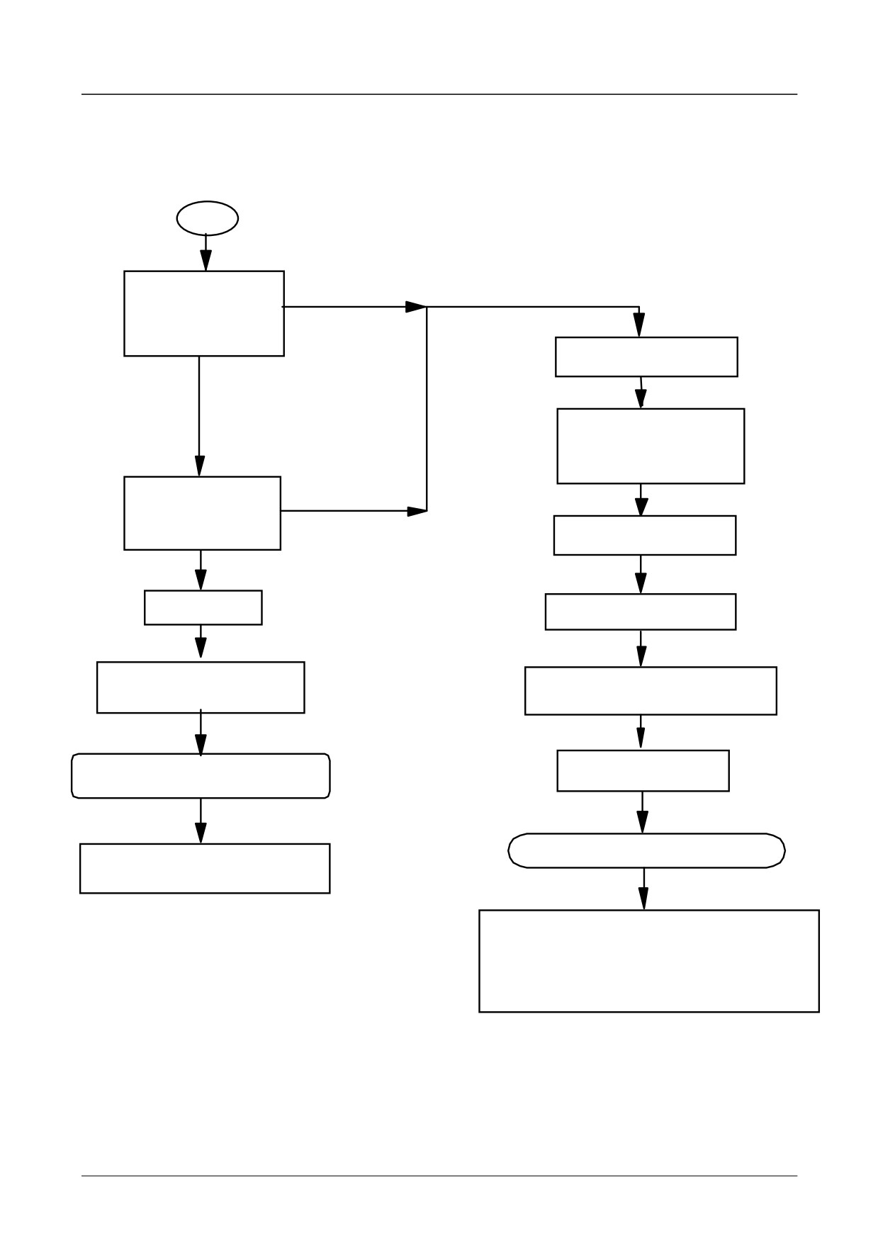
Figure 1-1 Parker SSD Drives EMC `CE' Mark Validity Chart
514C Product Manual
1-6 Product Overview
CERTIFICATES
514C
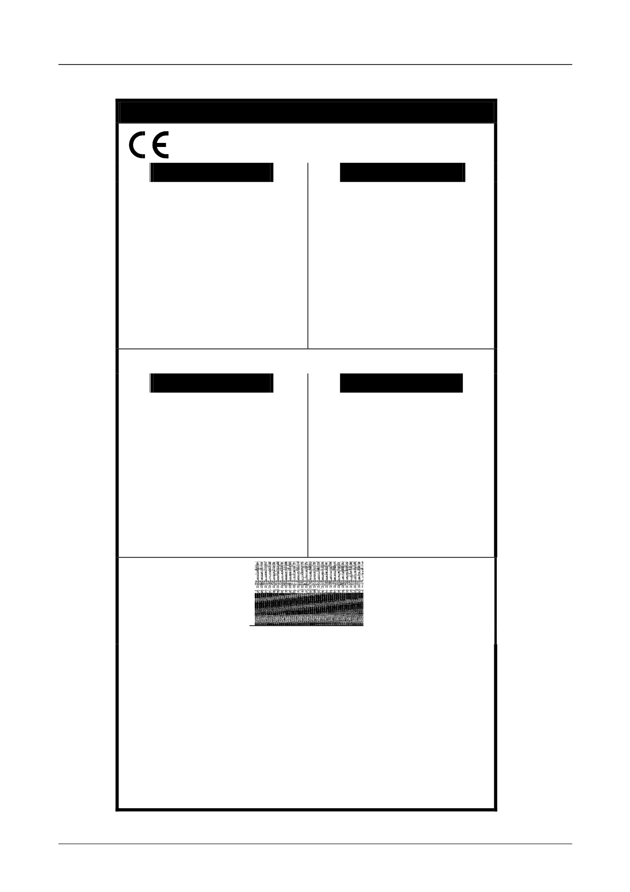
EC DECLARATIONS OF CONFORMITY
Date CE marked first applied: 01.04.2000
EMC Directive
Low Voltage Directive
Issued for
In accordance with the EEC Directive
The drive is CE
In accordance with the EEC Directive
compliance
marked in
2006/95/EC
with the EMC
2004/108/EC
accordance with
We Parker SSD Drives, address as below,
Directive when
the low voltage
We Parker SSD Drives, address as below,
declare under our sole responsibility that the
the unit is used
declare under our sole responsibility that the
directive for
above Electronic Products when installed and
as relevant
above Electronic Products when installed and
electrical
operated with reference to the instructions in
apparatus.
operated with reference to the instructions in
equipment and
the Product Manual
the Product Manual (provided with each piece
appliances in the
(provided with each piece of equipment), is in
of equipment) is in accordance with the relevant
voltage range
accordance with the relevant clauses from the
clauses from the following standard:-
when installed
following standard :-
correctly.
EN50178 (1998)
* BSEN61800-3 (2004)
MANUFACTURERS DECLARATIONS
EMC Declaration
Machinery Directive
This is
We Parker SSD Drives, address as below,
The above Electronic Products
Since the
provided to aid
declare under our sole responsibility that the
are components to be incorporated into
potential hazards
above Electronic Products when installed and
your
machinery and may not be operated alone.
are mainly
operated with reference to the instructions in
justification for
The complete machinery or installation using
electrical rather
the Product Manual (provided with each piece
this equipment may only be put into service
EMC
than mechanical,
of equipment) is in accordance with the
when the safety considerations of the Directive
compliance
the drive does not
relevant clauses from the following standard:-
89/392/EEC are fully adhered to.
when the unit
fall under the
Particular reference should be made to
is used as a
machinery
EN60204-1 (Safety of Machinery - Electrical
component.
* BSEN61800-3 (2004)
directive.
Equipment of Machines).
However, we do
All instructions, warnings and safety
supply a
information of the Product Manual must be
manufacturer's
adhered to.
declaration for
when the drive is
used (as a
component) in
machinery.
Dr Martin Payn (Conformance Officer)
* Compliant with the immunity requirements of the Standard without specified EMC filters.
690PB only when fitted with an internal or external filter.
PARKER SSD DRIVES
NEW COURTWICK LANE, LITTLEHAMPTON, WEST SUSSEX
BN17 7RZ
TELEPHONE:
+44(0)1903 737000 FAX:
+44(0)1903
737100
Registered Number:
4806503 England. Registered Office: 55 Maylands Avenue, Hemel Hempstead, Herts HP2 4SJ
514C Product Manual
Product Overview
1-7
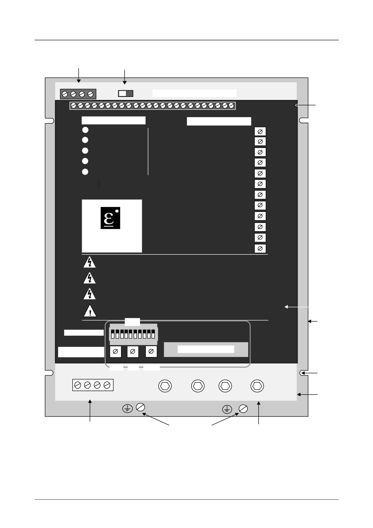
PRODUCT IDENTIFICATION
AUXILIARY
AUXILIARY SUPPLY
SUPPLY SELECTOR SWITCH
A1 A2 A3 A4
CONTROL TERMINAL BLOCK
CONTROL
PCB
242322212019181716 15141312 11 10 9 8
7 6 5 4 3 2 1
DIAGNOSTIC LEDS
POTENTIOMETERS
L1 POWER ON
RAMP UP
P1
L2 STALL TRIP
RAMP DOWN
P2
L3 OVERCURRENT
SPEED PROPORTIONAL
P3
L4 PLL LOCK
P4
SPEED INTEGRAL
L5 CURRENT LIMIT
CURRENT LIMIT
P5
CURRENT PROPORTIOP6
514C
CURRENT INTEGRAL P7
IR COMPENSATION
P8
P9
MAX SPEED CALIBRATIP1
0
EUROTHERM
ZERO SPEED ADJUST
P11
DRIVES
ZERO SPEED THRESHOP
12
CAUTION
Before Switching ON Refer to the Manual for Installation and Safety,
Switch and Transformer Setting Information.
CAUTION
Risk of Electric Shock - More than One Disconnect Switch may be Required
to De-energise the Equipment Before Servicing
AVERTISSEMENT
Risque de decharge electrique. La coupure de plusieurs interrupteurs pout
etre necessaire avant utilisation - voir le schema
LEGEND
CAUTION
PLATE
Compatible with Type B RCD Protection Devices Only
SW1
HEATSINK
ON
Option Switches
1 2 3 4 5 6 7 8 9 10
Current Calibration
DIAGNOSTIC SOCKET
Switches
SW2
SW3
SW4
Tens
Unit
Tenths
FIXING
POINTS
POWER
FL1 FL2 F- F+
L2/N
L1
A+
A-
PCB
FIELD TERMINALS
PROTECTIVE
POWER
GROUND
TERMINALS
514C Product Manual
1-8 Product Overview
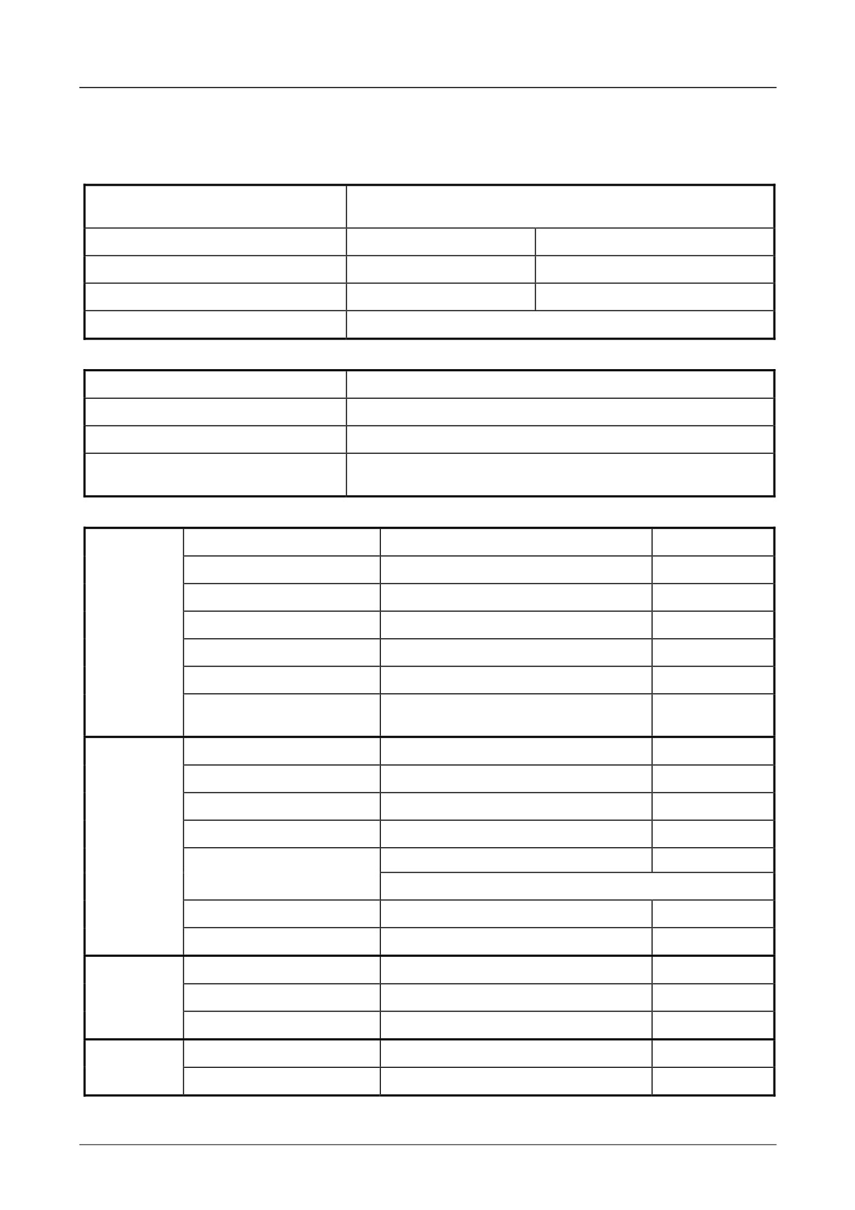
TECHNICAL SPECIFICATION
General
SPEED CONTROL
Control Action
Closed Loop with Proportional Integral Control and
Adjustable Stability
Speed Feedback
Armature Voltage
Tachogenerator
100% Load Regulation
2 % Typical
0.1 % Typical
Maximum Torque/Speed Range
20:1
100:1
Overload
150% for 60 seconds.
TORQUE CONTROL
Control Action
Closed Loop with Proportional Integral Control.
Accuracy
2 %
Overspeed
Inherent.
Overload
None 100% continuous (consideration must be given
to motor when operating at low speed).
INPUTS / OUTPUTS
Analogue
Setpoint Ramp
0 to ±10V
100 Kohm
Inputs
Positive Trim Setpoint
0 to ±10V
100 Kohm
Negative Trim Setpoint
0 to ±10V
100 Kohm
Current Limit
0 to +7.5V
50 Kohm
Current Demand
0 to ±10V
100 Kohm
Tachogenerator Input
0 to ±350Vdc
220 Kohm
Thermistor /
<200 ohm = Normal
5 Kohm
Microtherm Input
>1800 ohm = Overtemperature
Outputs
Setpoint Ramp
0 to ±10V
5 mA
Analogue
Total Setpoint
0 to ±10V
5 mA
Speed
0 to ±10V
5 mA
Current Demand
0 to ±10V
5 mA
Current Meter
0 to ±5V (0 to Ical)
5 mA
Bipolar or Modulus
See SW1/8
+10V Reference
+10V
5 mA
-10V Reference
- 10V
5 mA
Digital
Run
+10 to +24V
100 Kohm
Inputs
Enable
+10 to +24V
100 Kohm
Stall Override
+10
100 Kohm
Digital
Health
+24V
50 mA Source
Outputs
Zero Speed or Setpoint
+24V
50 mA Source
514C Product Manual
Product Overview
1-9
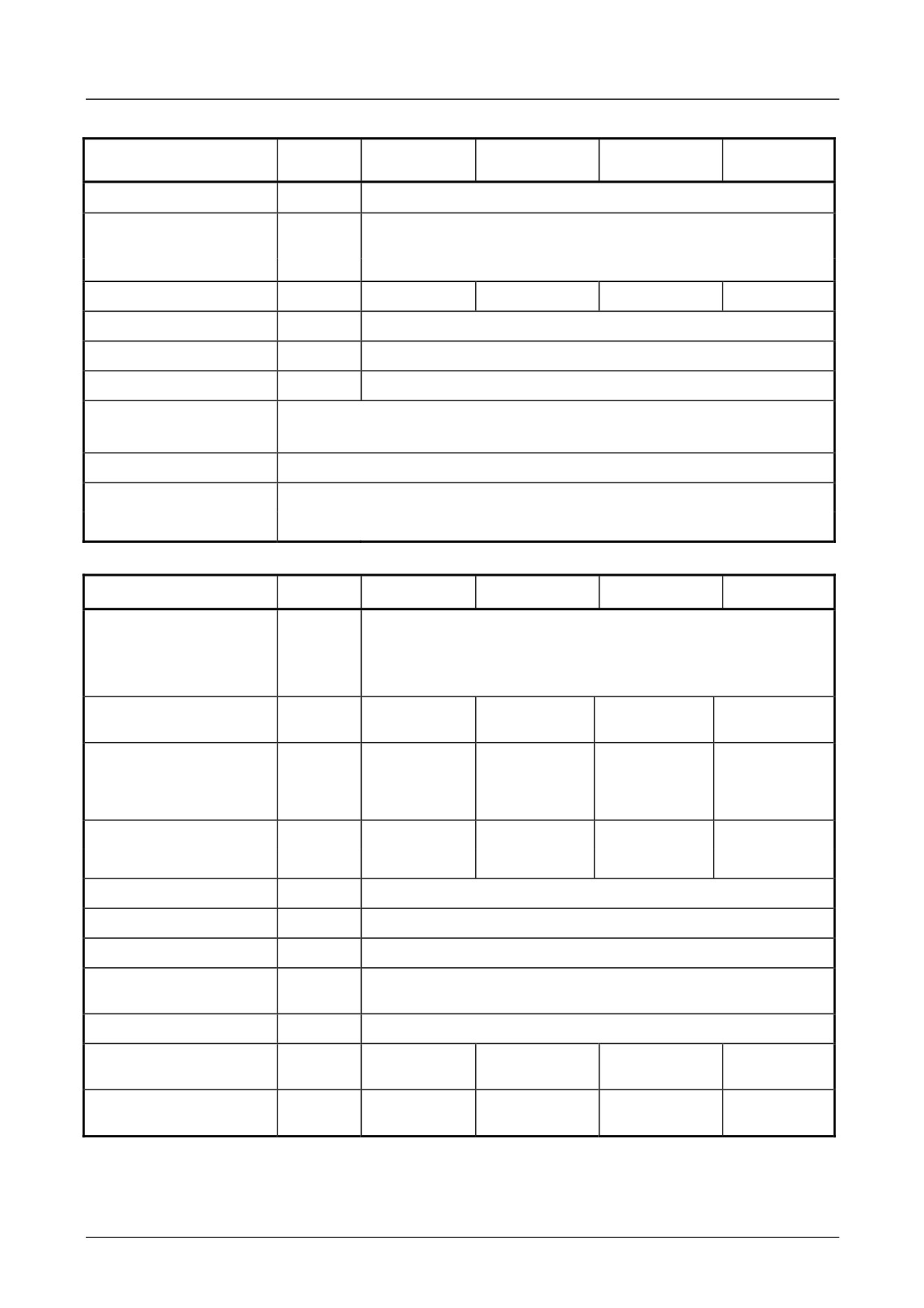
Electrical Ratings
INPUT RATINGS
SYMBOL
514C/04
514C/08
514C/16
514C/32
Supply Voltage
Vs
110 - 480 Vac ± 10%
Maximum Supply
480Vac L - L Non earth referenced (IT)
Voltage (Derived from
or earth referenced (TN)
Three Phase Supply)
480Vac L - N Earth referenced (TN)
Supply Current
Is
6A
12A
24A
48A
Supply Frequency
fs
50/60 Hz ñ 5 Hz
Auxiliary Supply
Vaux
110/120 or 220/240 Vac ±10%
Aux. Supply Current
Iaux
3A (Includes Contactor Coil Current)
Contactor Coil
3A Maximum
Current
Installation Category
Overvoltage Category III
Earth Leakage
Without Filter
-
5mA (1)
Current at 480Vac
With Filter
-
50mA
OUTPUT RATINGS
Nominal Armature
90 Vdc at 110/120 Vac
Voltage
Va
180 Vdc at 220/240 Vac
320 Vdc at 380/415 Vac
Maximum Armature
Ia
4A dc ±10%
8A dc ±10%
16A dc ±10%
32A dc ±10%
Current
Armature Current
Ical
0.1 to 4A
0.1 to 8A
0.1 to 16A
0.1 to 32A
Calibration 100%
in 0.1A
in 0.1A steps
in 0.1A steps
in 0.1A steps
steps
Nominal Motor Power
Pm
1.125kW
2.25 kW
4.5 kW
9 kW
at 320 Vdc Armature
HP
11/2 HP
3 HP
6 HP
12 HP
Overload
150% for 60 seconds
Field Current
If
3 A dc
Field Voltage
Vf
0.9 X Supply Voltage (Vs)
Maximum Armature
1.5
Form Factor
Thyristor I2t
300 A2s
Typical Controller
15W (2)
25W (2)
50W (2)
75W (2)
Dissipation at Ia 100%
UL Listed Rating @
HP
1/2 HP
1 HP
3 HP
5 HP
180V dc
Notes:-
(1)
Permanent earthing mandatory.
(2)
See page 3-2 for filter watt loss information.
514C Product Manual
1-10 Product Overview
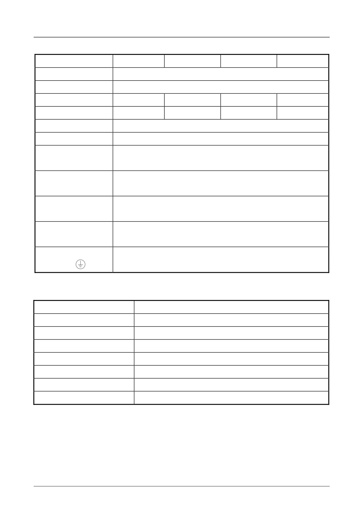
Mechanical
514C/04
514C/08
514C/16
514C/32
Overall Width
160mm
Overall Height
240mm
Overall Depth
90mm
90mm
130mm
130mm
Weight
1.6Kg
1.6Kg
3.0Kg
3.0Kg
Airflow Clearance
75mm Above and Below
Mounting Centres
210mm Vertical x 148mm Horizontal
Control Terminals -
Screw Terminals will accept 2.5mm2 stranded wire.
1 to 24
Terminal Tightening Torque 0.45 Nm, 4.0 lbf-in.
Auxiliary Supply
Screw Terminals will accept 4mm2 stranded wire.
Terminals - A1 to A4
Terminal Tightening Torque 0.5 Nm, 4.5 lbf-in.
Field Terminals - FL1,
Screw Terminals will accept 4mm2 stranded wire.
FL2, F-, F+
Terminal Tightening Torque 0.5 Nm, 4.5 lbf-in.
Power Terminals -
M5 Studs with Clamp.
L2/N, L1, A+, A-
Terminal Tightening Torque 2.7 Nm, 24 lbf-in.
Earth (Grounding)
M5 Cheese Head Screw.
Terminals
Terminal Tightening Torque 7.1 Nm, 63 lbf-in.
ENVIRONMENTAL REQUIREMENTS
Enclosure
Chassis Mounting IP00 (UL open-type)
Operating Temperature
0 to +40oC. (Derate 1.5%/Degree above 40oC).
Humidity
85% R.H. at 40oC.
(Non-condensing).
Altitude
Above 1000m derate at 1% / 100m.
Storage Temperature
-25oC to +55oC.
Pollution
Pollution Degree 2.
Transport Temperature
-25oC to +70oC.
Overvoltage
III
514C Product Manual

Product Overview
1-11
EMC TECHNICAL RATINGS
Immunity
Port
Phenomenon
Test Standard
Level
Criterion
Generic
Standard
Enclosure
ESD
BS EN 61000-4-2
8kV AD
Self Recovery
EN50082-1
Port
RF Field
(1995)
10V/m,1kHz, AM
No Change
(1992),
RF Field Pulse
ENV 50140 ENV
10 V/m P.M.
Self Recovery
and
Modulation
50204
EN50082-2
Power
Fast Transient
BS EN 61000-4-4
2kV
Self Recovery
(1995)
Ports
Burst
(1995)
Bulk Current
ENV 50141
10V, 1kHz, AM
No Change
Injection
Surge Test
BS EN 61000-4-5
2kV Common
Self Recovery
(1995)
Mode
2kV Differential
Mode
Signal &
Fast Transient
BS EN 61000-4-4
2kV
Self Recovery
Control
Burst
(1995)
Bulk Current
ENV 50141
10V, 1kHz, AM
No Change
Injection
Power
Fast Transient
BS EN 61000-4-4
2kV
Self Recovery
Interfaces
Burst
(1995)
Bulk Current
ENV 50141
10V, 1kHz, AM
No Change
Injection
Emissions
Port
Phenomenon
Test Standard
Level
Generic
Standard
Enclosure Port
Radiated
EN55011
Class B #
EN50081-1 (1992),
Power Port
Conducted
EN55011
Class B *
EN50081-2 (1994)
Notes: These levels of performance are achieved when installed as specified with the
recommended Supply Filter.
Achieved with up to 50m of motor cable.
#
Achieved with unscreened signal
and control cables.
PRODUCT CODE
Block
Product
Code
Feature
1
Basic Product
514C
2
Current Rating
04
4 amp
08
8 amp
16
16 amp
32
32 amp
3
Livery
00
Standard
01 to 99
Customer
4
Cover
00
IP00 Open Frame
5
Special Options
00
Standard
01-99
Documented Special Options
514C Product Manual
2-1 Pre-Installation Planning
Chapter 2 Pre-Installation Planning
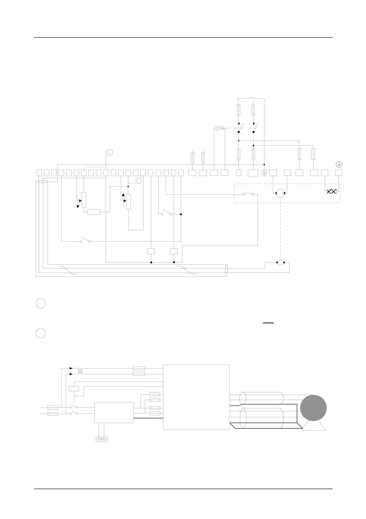
BASIC WIRING DIAGRAMS
Basic Connection
Mains Supply
Branch Protection (Fuses or Circuit Breaker)
AC Supply Contactor
Signal Ground
Auxillary AC Supply
1
FS3
FS4
FS1
FS2
FS5
FS6
GND
1
3
4
5
6
7
8
9
10
11
12
13
14
15
16
19
20
22
23
24
A4
A3
A2
A1
L1
L2/N
A+
A-
FL1
FL2
F+
F-
PE
2
GRD
Microtherm
0 to
10K
DC Motor
100%
10K
10K
EXTERNAL
SPEED
CURRENT
SETPOINT
LIMIT
ENABLE
(Optional)
RUN
Health Relay
Speed Relay
TACHOGENERATOR
OPTIONAL
PE
1
It is recommended that the “0V/common” be connected to protective earth/ground for safety
reasons. In a system comprising of more than one controller, the 0V/common” signals
should be connected together and joined to protective earth/ground at one point only.
2
Stall override link between terminals 14 and 15 required when using controller in current
control.
EMC Connections With Filter
A3
A4
A1
Screened Cable
DC Motor
A2
FL1
F+
AC Supply
FL2
Product
F-
L1
PE
A+
Filter
L2
A-
PE
PE
PE
Screened Cable
PE
514C Product Manual

Pre-Installation Planning
2-2
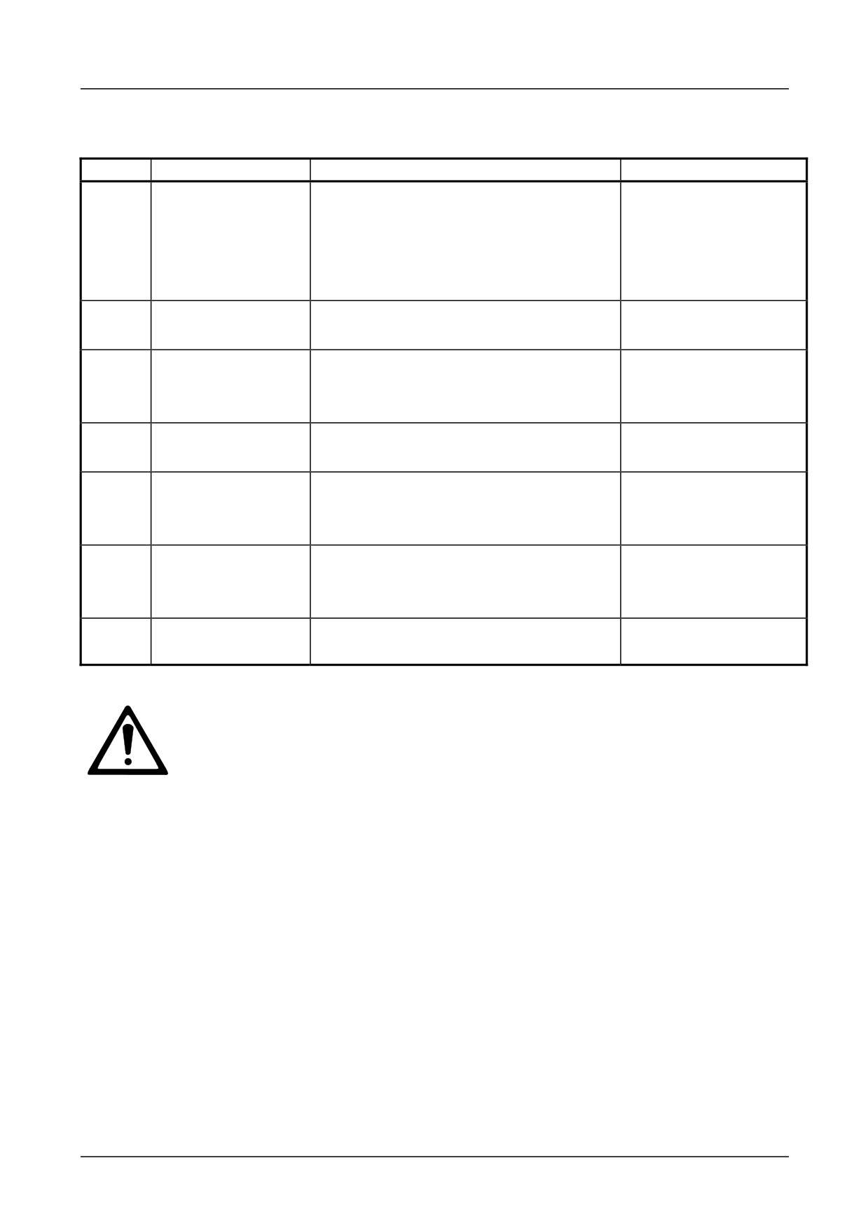
TERMINAL DESCRIPTIONS
Control Terminals
TERMINAL
FUNCTION
DESCRIPTION
NOTES
T1
Tacho Feedback
Motor Mounted Tachogenerator Input.
+350 Vdc Max. Approx
Proportional to Motor Speed.
220 kohm.
T2
Not Connected
T3
Speed Meter Output
Analogue Output,
5mA output
0 to ±10V for 0 to ±100% Speed.
S/C protected
T4
DO NOT USE
Pending Change.
T5
Run Input
Digital Input to Run Controller.
+24V to Run.
0V to Stop.
T6
Current Meter
Analogue Output, 0 to +7.5V =
5mA output
Output
±150% Calibrated Current
S/C protected
SW1/5 Off = Bipolar
SW1/5 On = Magnitude
T7
Torque/Current
Analogue Input,
approx.
Limit Input
0 to +7.5V = 0 to 150% of Calibrated
100 kohm
Current.
T8
0V Common
Analogue / Digital Signal Common
T9
Setpoint Ramp
Analogue Output,
5mA output
Output
0 to ±10V = 0 to ±100% Ramped
S/C protected
Setpoint.
T10
Positive Trim Speed
Analogue Input,
approx.
Setpoint Input
0 to ±10V = 0 to ±100% Speed.
100 kohm
T11
0V Common
Analogue / Digital Signal Common.
T12
Total Setpoint Sum
Analogue Output,
5mA output
Output
0 to ±10V = 0 to ±100% Speed.
S/C protected
T13
Setpoint Ramp Input
Analogue Input,
approx.
0 to +10V = 0 to 100% Forward
100 kohm
Speed.
0 to -10V = 0 to 100% Reverse Speed.
T14
+10V Reference
Analogue Output,
5mA output
Output
+10V Reference for Speed/ Current
S/C protected
Setpoints.
T15
Stall Override Input
Digital Input to Override Stall Detection
approx.
+10V = Override.
100 kohm
T16
-10V Reference
Analogue Output,
5mA output
Output
-10V Reference for Speed/ Current
S/C protected
Setpoints.
T17
Negative Trim
Analogue Input,
approx.
Speed Setpoint
0 to +10V = 0 to 100% Reverse Speed
100 kohm
Input
0 to -10V = 0 to 100% Forward Speed.
514C Product Manual
2-3 Pre-Installation Planning
TERMINAL
FUNCTION
DESCRIPTION
NOTES
T18
Current Demand
Analogue Input or Output:
5mA output
Input / Output
SW1/8 'ON' = Current Demand
S/C protected approx.
Output.
100 kohm.
SW1/8 'OFF' = Current Demand Input.
0 to ±7.5V = 0 to ±150% Current.
T19
Health Output
Digital Output,
50mA Source
+24V = Healthy.
Short Circuit Protected.
T20
Enable Input
Digital Input to Enable Controller.
100k approx.
+10V to +24V to Enable.
0V to Disable.
T21
Inverted Setpoint
Analogue Output,
5mA output
Sum Output
0 to -10V = 0 to 100% Forward Speed.
S/C protected.
T22
Thermistor /
Motor Thermistor or Microtherm Sensor
5k approx.
Microtherm Input
<200 ohm to 0V = Normal.
>1800 ohm to 0V= Overtemperature.
T23
Zero Speed Output
Digital Output,
50mA Source
/Zero Setpoint
+24V = Stopped/Zero Setpoint.
Short Circuit Protected.
Output
0V = Running/Non zero setpoint.
T24
+24V
+24V Supply Output.
20mA. For use on the
drive only.
The +24v supply from the drive (terminal T24) is for use with the drive only. It
should be used with the RUN circuit (terminal 5) to control the drives internal
relay to switch the contactor and can be used with the ENABLE circuit (terminal
T20).
Caution
DO NOT use the +24v supply to power any circuit or device external to the
drive. This includes external relays, PLC’s, and any other equipment.
Using the +24v external to the drive could result in drive malfunction or damage,
damage to connected equipment, and could endanger personnel.
514C Product Manual

Pre-Installation Planning
2-4
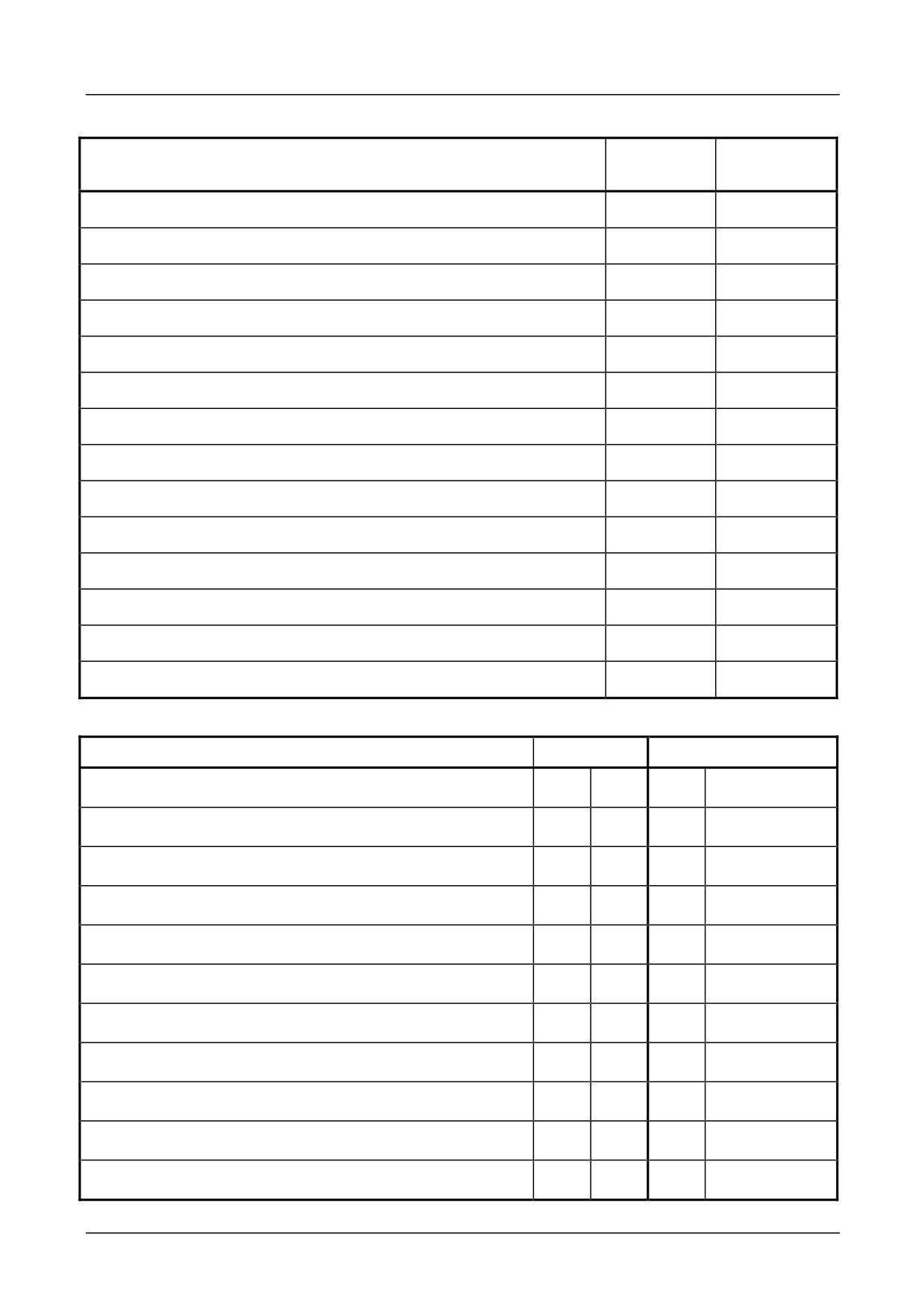
TERMINAL COMPARISON 540/1 TO 514C
Function
Terminal
Terminal
540/1
514C
Common
A1
T8
Armature Current (Direct)
A2
-
Setpoint Ramp Reset
A3
-
Setpoint Ramp Input
A4
T13
Setpoint Ramp Output
A5
T9
Setpoint Input 1 - Positive Trim Speed Setpoint I/P
A6
T10
Setpoint Input 2
A7
-
Inverted Sub-Total Output - Inverted Setpoint Sum O/P
A8
T21
Setpoint Input 3 (Inverted) - Negative Trim Speed Setpoint I/P
A9
T17
Total Setpoint
A10
T12
+10V Reference
A11
T14
-10V Reference
A12
T16
Common
B1
T11
Tachogenerator Input
B2
T1
Current Demand Isolate
B3
-
Current Demand Output
B4
T18
Auxiliary Current Demand Input
B5
T18
Select Auxiliary Current Input
B6
-
Auxiliary Current Limit Positive
B7
-
Main Current Limit
B8
T7
+10V Reference
B9
T14
Auxiliary Current Limit Negative
B10
-
Buffered Speed Output
B11
T3
Buffered Current Output
B12
T6
514C Product Manual
2-5 Pre-Installation Planning
Function
Terminal
Terminal
540/1
514C
Common
C1
T8/11
Thermistor
C2
T22
Auxiliary Enable
C3
-
+24V
C4
T24
Enable
C5
T20
Maintain
C6
-
Start / Run
C7
T5
Ready Output
C8
-
Zero Speed Output
C9
T23
Drive Operational / Health
C10
T19
+24V
C11
T24
Unused
C12
-
DO NOT USE Pending Change
-
T4
Stall Override
-
T15
Switches
Function
540/1
514C
Speed Calibration
No
Yes
SW1/2
Tachogenerator or Armature Voltage
No
Yes
SW1/3
Zero Output Speed or Setpoint
No
Yes
SW1/4
Current Bipolar or Modulus
Yes
S1
Yes
S1/5
Ramp Isolate
Yes
S3
Yes
SW1/6
Standstill
Yes
S2
Yes
SWQ1/7
Current Demand Output or Current Demand Input
No
Yes
SW1/8
Contactor Dropout on Overcurrent
No
Yes
SW1/9
Standstill Comparator Source
No
Yes
SW1/10
Ramp Rate
Yes
S4
No
Current Calibration
No
Yes
SW2/3/4
514C Product Manual
Pre-Installation Planning
2-6
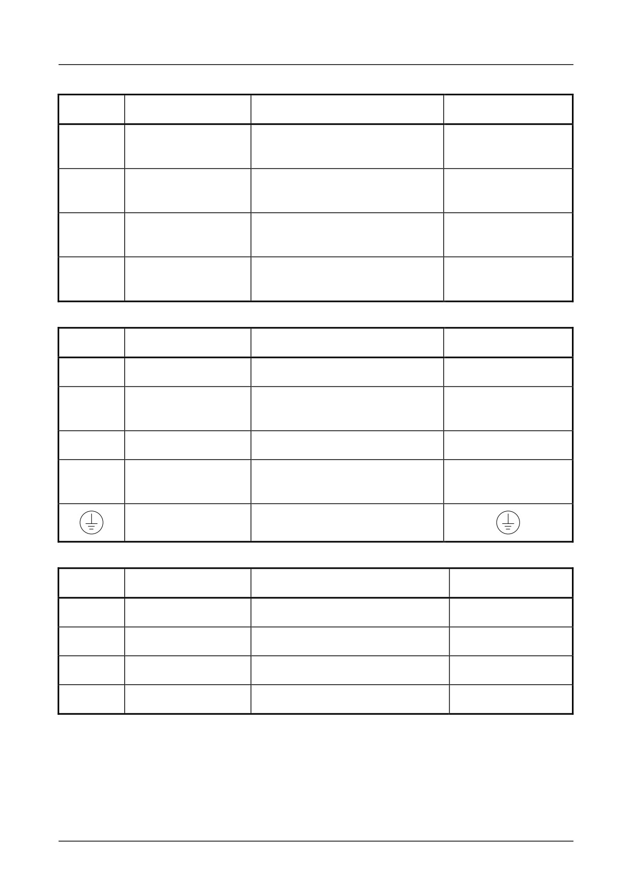
Auxiliary Supply Terminals
TERMINAL
FUNCTION
DESCRIPTION
NOTES
A1
AC Supply
AC Supply to AC Supply
540/1 Terminal D12
Contactor Coil.
Contactor Switched Live.
A2
AC Supply
AC Supply to AC Supply
540/1 Terminal D11
Contactor Coil.
Contactor Neutral.
A3
Auxiliary AC Supply
Auxiliary Supply for Power
540/1 Terminal D10
Neutral.
Supplies and Contactor.
A4
Auxiliary AC Supply
Auxiliary Supply for Power
540/1 Terminal D9
Live.
Supplies and Contactor.
Power Terminals
TERMINAL
FUNCTION
DESCRIPTION
NOTES
L1
AC Input Line 1
Mains Supply Line 1 Input
L1
L2/N
AC Input Line 2/
Mains Supply Line 2 Input or
L2/N
Neutral
Neutral
A+
Armature Positive
Motor Armature Positive Output.
A+
A-
Armature Negative
Motor Armature Negative
A-
Output.
Ground
Field Terminals
TERMINAL
FUNCTION
DESCRIPTION
NOTES
F-
Field Negative
Motor Field Negative DC Output
540/1 Terminal D7
F+
Field Positive
Motor Field Positive DC Output
540/1 Terminal D5
FL2
Field Rectifier Supply
Mains Supply Input Field Rectifier
540/1 Terminal D3
FL1
Field Rectifier Supply
Mains Supply Input Field Rectifier
540/1 Terminal D1
514C Product Manual
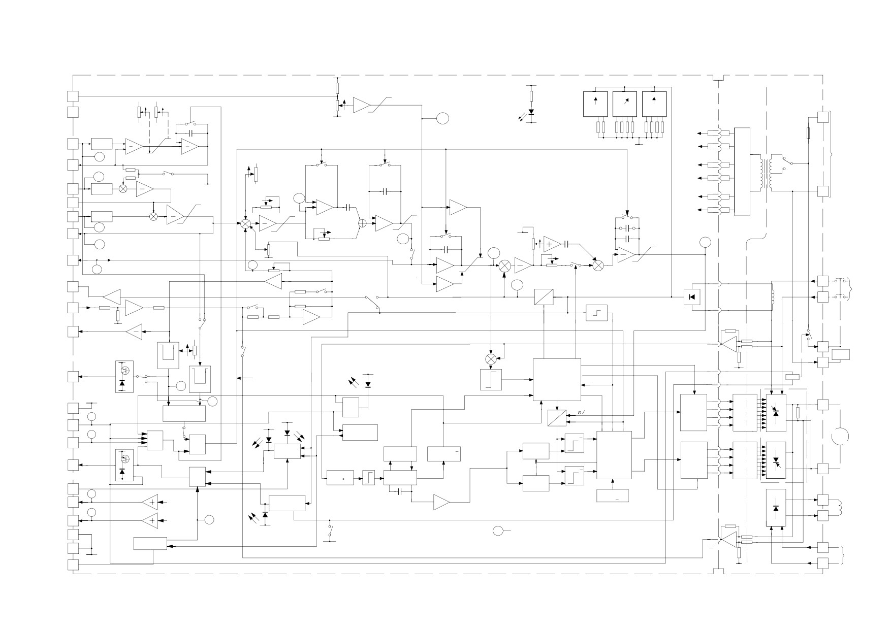
BLOCK DIAGRAM
+10V
TENS
UNITS
TENTHS
ISOLATION
+24V
SW2
SW3
SW4
BOUNDARY
CURRENT
7.5V
9
01
90
1
9
0
1
LIMIT
7
CURRENT
MAIN
8
2
8
2
8
2
UP
CURRENT
+
POWER
7
3
7
3
7
3
CALIBRATION
DOWN
LIMIT
4
6
4
65
4
4
RATE
RATE
LED 1
6
5
5
P1
P2
P5
0V
0V
Z24
A4
-24V
AUXILIARY
+24V
+24V
SUPPLY
SETPOINT
FUSE
RAMP
13
FILTER
0V
SELECT
INPUT
+15V
+15V
VOLTAGE
REQUIRED
AUXILIARY
Z11
220/240
SUPPLY
RAMP
+2%
9
0V
0V
OUTPUT
P11
(SIGNAL)
110/120
ZERO
Z12
RAMP ISOLATE
SPEED
0V
0V
POSITIVE
SW1/6
0V
ADJUST
TRIM
-2%
SETPOINT
10
FILTER
++
SPEED PROP GAIN
A3
INVERTED
Z17
-15V
-15V
SETPOINT
+11V
P3
21
SUM
+
+
P6
+10V
-24V
-24V
NEGATIVE
+10V
CURRENT
TRIM
17
FILTER
++
PROPORTIONAL
+
+
S.O.T.
SETPOINT
+
+
+
-
GAIN
Z14
-11V
-
TOTAL
-10V
0V
12
-10V
SETPOINT
Z19
Z15
P4 SPEED INTEGRAL
10V
Z27
P8
GAIN
CURRENT
IR
DEMAND
A
Z25
CURRENT
COMP
ISOLATE
IM
DEMAND
18
SW1/8
+
PHASEANGLE
INPUT/
Z16
P10
-
A
+
+
-10V
OUTPUT
Z18
IS
+
P7
CURRENT
MAX SPEED CAL
INTEGRAL
BUFFERED
G
GAIN
L2/N
CURRENT
6
SW1/1
BIPOLAR/
-
Z26
A.C.C.T.
MAIN
100%=5V
MODULUS
+1
SUPPLY
+1
L1
SW1/2
-1
TACHO
SW1/5
INPUT
1
+1
IA>0
IA=0
SPEED
BUFFERED
SW1/10
CALIBRATION
SPEED
3
OUTPUT
0.5%
-
ZERO
ARMATURE
L
SPEED
+
A1
THRESHOLD
VOLTAGE FEEDBACK
SCAN
CODING
P12
ENABLE
-
SW1/3
+
N
+24V
SW1/4
ZERO
10%
CURRENT
S1
A2
SPEED
PLL
DEMAND
M
CONTACTOR
MAIN
SYNC
COIL
ZERO
M
POLARITY
S
OUTPUT
23
SYSTEM
LED4
RLA
ZERO
Z8
ZERO
ENABLE
S
IA=0
0V
OUTPUT
SELECT
S.P
MOUNTED ON
CLOCK
E/S
HEATSINK
PLL SYNC
M1
T1-T4
TH1-4
+24V
Z7
2 I/P
FIRING
+
PULSE
A+
24
2 I/P
AND
GATE
CIRCUITS
RB
Z9
AND GATE
CURRENT
+1
TRANS'FR
LIMIT
P.L.L. SYNC
SOFT START
MASTER
-
-1
RUN
5
STANDSTILL
LED5
SLAVE
MASTER
LOGIC ENABLE
RESET
Z5
4 I/P
GENERATOR
AND
2 I/P
SW1/7
LED2
COMP
GATING
ENABLE
20
LOGIC
GATE
OR
AUTO
T5-T8
TH5-8
MOTOR
+24V
GATE
STALL
STALL
DIVIDE
P.L.L. SYN
C
RANGE
+
ARMATURE
DETECTION
256
DETECTOR
RAMP
FIRING
FIRING
PULSE
NO FAULT
RAMP
PULSE&
CIRCUITS
HEALTH
19
END STOP
SLAVE
TRANS'FR
RESET
COMP
-
A-
3 I/P
GENERATION
NERGISED WHEN DRIVE O.K) 50mA.
OR
FILTER
PHASE
SLAVE
SLAVE
0V
-90
LOCK LOOP
AUTO
STALL
GATE
RANGE
OVER RIDE
15
RAMP
Z2
PULSE
+10V
+10V
OSC
+
+
PRECISION
14
OVERCURRENT
-1
F+
REFERENCE
INTERNAL
TRIP
MOTOR
(10mA)
FIELD
Z3
-
F-
-10V
-10V
LED3
-
PRECISION
16
Z6
REFERENCE
INTERNAL
OVERCURRENT
(10mA)
OVERCURRENT
RELAY
Z
CUSTOMER DIAGNOSTIC
11
SOCKET
+
DROPOUT
THERMISTOR
SW1/9
-
TRIP
0V
VA
8
50
FL1
A.C
FIELD
0V (SIGNAL)
RUN
SUPPLY
THERMISTOR/
FL2
MICROTHERM
22
ISOLATION
BOUNDARY
2-8 Pre-Installation Planning
FUNCTIONAL DIFFERENCES 514C - 540
Feature
540 Series
514C
Overload
Inverse Time reduced Current
Stall Detection & Timed Inhibit.
Limit.
Overload
200% for 10 seconds.
150% for 60 seconds.
Overcurrent
-
300% Instantaneous Trip.
Ramp
0.1 to 2 secs or 1 to 20 secs.
1 to 40 seconds.
Ramp Reset
Internal & External.
Internal.
Speed Setpoint
Ramp, Input No 1, Input No 2
Ramp, Positive Trim & Negative Trim
Inputs
and Inverted Input No 3.
Input.
Auxiliary Current
Auxiliary Current Limit of Positive
Not Provided.
Clamp Positive
Demand.
Auxiliary Current
Auxiliary Current Limit of
Not Provided.
Clamp Negative
Negative Demand.
Current Demand
Speed Loop Current Demand
Current Demand O/P or Ext. Current
Output
Output.
Demand I/P.
Current Demand
Isolates Speed Loop Current
DIL Switch Selectable.
Isolate
Demand from Current Path.
External Current
Additional Current Demand.
Current Demand O/P or Ext. Current
Demand I/P
Demand I/P.
Current Demand
Enable Input of External Current
Not Provided.
Connect
Demand.
Armature Current
External IR Compensation via
Internally provided.
Output
Armature Current Output.
Auxiliary Enable
External Trip / Enable.
Not Provided.
Ready
Drive Ready Output.
Not Provided.
Stop Input
Maintain for Momentary Start.
Not Provided.
Field Fail
Field Current detector.
Not Provided.
Stack Fuses
Semiconductor Fusing.
Not Provided.
Relays
Output Sink unprotected.
Output Source Short Circuit Protected.
EMC
Complies with EMC Directive.
LVD
Complies with Low Voltage Directive.
WARNING
THE 514C IS NOT A DIRECT REPLACEMENT FOR THE 540/1. IT IS
FUNCTIONALLY EQUIVALENT.
NOTE WHEN A 514C IS USED TO REPLACE A 540 WITH THE HEALTH AND/OR ZERO
SPEED RELAYS UTILISED, THE RELAYS MUST BE RECONNECTED BETWEEN
OUTPUT AND SIGNAL COMMON NOT +24V.
Setting up & Commissioning
3-1
Chapter 3 Installation Procedure
INSTALLATION PRECAUTIONS
Before connecting AC supplies to this equipment.
1) Ensure good airflow over the heatsink. Maintain clearance of 75mm above and below
controller. For safety maintain a clearance of 20mm at the sides of the controller.
2) Operating temperature range does not exceed 0 to +40øC.
3) Controller is used in a Pollution Degree 2 environment.
4) Avoid vibration.
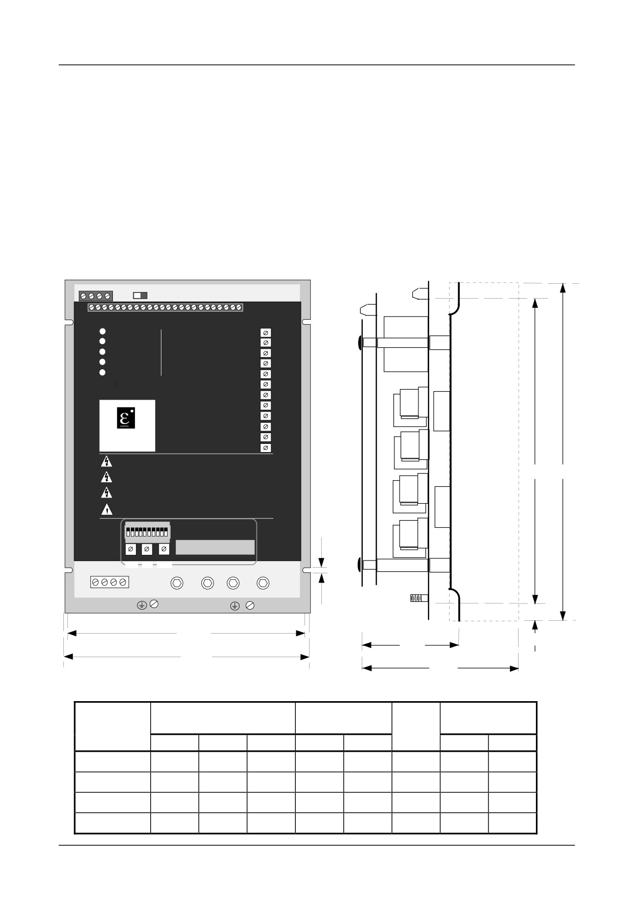
MECHANICAL INSTALLATION
L1 POWER ON
RAMP UP
P1
L2 STALL TRIP
RAMP DOWN
P2
L3 OVERCURRENT
SPEED PROPORTIONAP
3
L4 PLL LOCK
SPEED INTEGRAL
P4
L5 CURRENT LIMIT
CURRENT LIMIT
P5
CURRENT PROPORTI P6AL
514C
CURRENT INTEGRAL P7
IR COMPENSATION
P8
P9
MAX SPEED CALIBRATP10
EUROTHERM
P11
ZERO SPEED ADJUST
DRIVES
ZERO SPEED THRESH
P12
CAUTION
Before Switching ON Refer to the Manual for Installation and Safety,
Switch and Transformer Setting Information.
D
A
CAUTION
Risk of Electric Shock - More than One Disconnect Switch may be Required
to De-energise the Equipment Before Servicing
AVERTISSEMENT
Risque de decharge electrique. La coupure de plusieurs interrupteurs pout
etre necessaire avant utilisation - voir le schema
CAUTION
Compatible with Type B RCD Protection Devices Only
SW1
ON
1 2 3 4 5 6 7 8 9 10
SW2
SW3
SW4
Tens Unit
Tenths
G
FL1 FL2 F- F+
L2/N
L1
A+
A-
E
F
C
B
(measurement for 514C/04 and 08)
C
(measurement for 514C/16 and 32)
PRODUCT
OVERALL
FIXING
SIZE
SLOT DETAIL
DIMENSIONS
CENTRES
A
B
C
D
E
F
G
514C/04
240mm
160mm
90mm
210mm
148mm
M6
15mm
7mm
514C/08
240mm
160mm
90mm
210mm
148mm
M6
15mm
7mm
514C/16
240mm
160mm
130mm
210mm
148mm
M6
15mm
7mm
514C/32
240mm
160mm
130mm
210mm
148mm
M6
15mm
7mm
514C Product Manual
3-2 Setting up & Commissioning
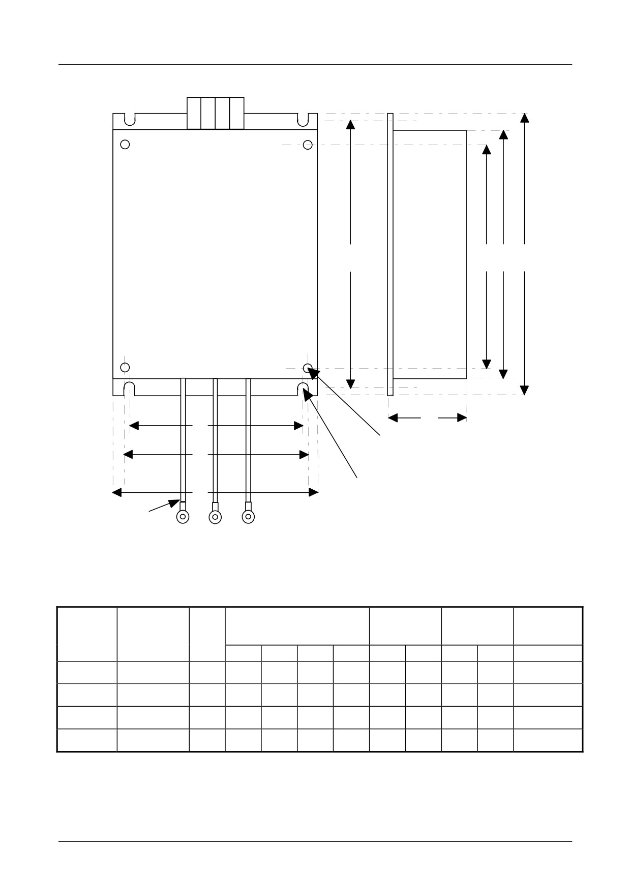
Filter
LINE
PE
PE
L1
L2
C E L
A
H
B
4 Holes M6 Insert
D
4 Holes M6 Clearance
W
230mm Leads
M5 Ring Lugs
PE L1
L2
LOAD
Green Red Black
/Yellow
Product
Filter
Watt
Overall Dimensions
Fixing
Product
Terminal
Loss
Centres
Fixing
L
W
H
E
A
B
C
D
514C/04
CO389113
18W
264
165
45
240
253
120
210
148
4mm2
514C/08
CO389113
18W
264
165
45
240
253
120
210
148
4mm2
514C/16
CO389113
18W
264
165
45
240
253
120
210
148
4mm2
514C/32
CO389114
36W
264
165
70
240
253
120
210
148
6mm2
514C Product Manual
Setting up & Commissioning
3-3
Installation Information
MOTOR
1) Ensure motor is mechanically secure and mounted according to manufacturers
specifications and practice.
2) Inspect brush gear, ensure commutator is in good condition and brushes are free to move
in brush box and in good condition.
3) Check obstructions in motor vents to maintain cooling air path.
4) Ensure motor armature choke (if specified) is correctly wired.
5) Ensure motor is free to rotate and that pulleys and couplings are correctly aligned.
6) Ensure transit damage has not occurred to motor windings or connections. Disconnect the
controller before carrying out electrical measurement e.g. insulation resistance.
ELECTRICAL INSTALLATION
RECOMMENDATIONS
1) Although the controller is designed to provide double or reinforced insulation between the
user and bare live parts, it is recommended that the “0v/Signal Ground” is earthed. Where
a number of controllers are used in a system the “0v/Signal Ground” terminals should be
grounded together and earthed at one point.
2) The controller is designed for armature current form factor of 1.5 or less. It is
recommended that a armature choke be fitted where a form factor of less than 1.5 current
cannot be guaranteed.
3) Due to the earth leakage currents the controller and filter should be permanently earthed.
This can be achieved by either connecting two earthing conductors of the required value,
see table 3.1, or connecting one earthing conductor of at least 10mm2.
4) Unused Analogue Inputs should be “grounded” (i.e., connected to 0V/Signal Ground) to
eliminate interference.
WIRING
1) Control cabling 0.75sq.mm minimum.
Auxiliary supply cable
1.5mm2
Field cable
1.5mm2
2) Power cable to be minimum 600VAC rated at 1.5 x armature current.
3) High speed semi-conductor fuses of the correct rating are recommended for incoming
supply protection. The 514C is not internally fused.
4) Ensure a protective earth connection is made compatible with the rating.
5) Isolated control wiring should not be run close to the power cabling. If screened cables
are used (recommended on setpoints and tachogenerators) connect screens to earth only at
controller end.
6) SSD Drives can supply fuse assemblies which can be bulkhead mounted and also act as
convenient supply isolators.
514C Product Manual

3-4 Setting up & Commissioning
Function
Rating
Cable Size
Fuse Isolator Kit
Fuse
ED Part No.
Rating
514C/04
Supply
6A
1.5mm2/16AWG
LA057605U012
12A fuse
CH390123
Motor
4A
1.5mm2/16AWG
(10A U.S.)
Ground
1.5mm2/16AWG
514C/08
Supply
12A
2.5mm2/14AWG
LA057605U016
16A fuse
CH390163
(15A U.S.)
Motor
8A
2.5mm2/14AWG
Ground
2.5mm2/14AWG
514C/16
Supply
24A
6mm2/10AWG
LA057605U032
32A fuse
CH390323
(30A U.S.)
Motor
16A
6mm2/10AWG
Ground
6mm2/10AWG
514C/32
Supply
48A
16mm2/6AWG
LA057605U050
50A fuse
CH390054
(60A U.S.)
Motor
32A
16mm2/6AWG
Ground
16mm2/6AWG
ALL
Field
3A
1.5mm2/16AWG
LA054664
10A
CH230014
TABLE 3.1 Recommended Cable Sizes.
Note:- The cable sizes shown are based on a Form Factor of 1.5 and an overload allowance of
110% (giving a multiplier of 1.65), they are selected for the notional rating of each controller.
Smaller cable may be used if the controller is calibrated at a lower current level.
Terminal Tightening Torques
Control
0.45 Nm
0.33 lbf-ft
4.0 lbf-in
Auxiliary Supply & Field
0.5 Nm
0.375 lbf-ft
4.5 lbf-in
Power
2.7 Nm
2 lbf-ft
24 lbf-in
Earth (Grounding)
7.1 Nm
5.25 lbf-ft
63 lbf-in
514C Product Manual
Setting up & Commissioning
3-5
REQUIREMENTS FOR UL COMPLIANCE
UL and c-UL Listing applicable to 514C/04, 514C/08 and 514C/16 Series only.
Motor Overload Protection
An external motor overload protective device must be provided by the installer.
This device can be a thermal sensor located within the motor winding monitored by the
microtherm input but this combination cannot be evaluated by Underwriters Laboratories Inc.,
hence it is the responsibility of the installer/local inspector determine whether the
combination is in compliance with the National Electrical Code NEC/NFPA-70, or local code
requirements.
Field Grounding Terminals
The International Grounding Symbol
(IEC Publication 417, Symbol 5019) is used to
designate the field grounding terminals.
The field grounding terminal is a single screw, sized No. 10 (M5). UL Listed (ZMVV)
pressure wire connectors rated No. 14 AWG (copper) must be used for Models 514C/04,
514C/08. UL Listed (SMVV) pressure wire connectors rated No. 10 AWG (copper) must be
used for Models 514C/16.
Short Circuit Protection
UL Listed fuses, Class RK5, rated 250V ac or 600V ac (as appropriate, depending on the
rated input voltage of the drive), 50A maximum, must be installed upstream of the drive.
Short Circuit Rating
Models rated more than 1Hp. Suitable for use on a circuit capable of delivering not more
than 5000 RMS Symmetrical Amperes, 480V maximum.
Operating Ambient Temperature
The maximum operating ambient temperature rating is 40oC.
Field Wiring Temperature Rating
Use 60oC or 60/75oC copper conductors only.
Field Wiring Terminal Markings
For terminal connections, refer to page 2-6, “Auxiliary Supply terminals”, “Power
Terminals”, “Field Terminals” and page 2-2, “Control Terminals”.
Power Field Wiring Terminals
The pressure terminal connectors provided on models 514C/04, 514C/08 accept a maximum
copper conductor size of No. 14 AWG. The pressure terinal connectors provided on models
514C/16 accept a maximum copper conductor size of No. 10 AWG.
Terminal Tightening torque
Refer to page 3-4 “Terminal Tightening Torques” for the tightening torques for power,
control and grounding terminals.
514C Product Manual

4-1 Setting up & Commissioning
Chapter 4 Setting-Up & Commissioning
OPTION SWITCHES
Speed Feedback
SW1/1
SW1/2
FEEDBACK VOLTAGE
OFF
ON
10 -
25V
USE P10 TO TRIM
ON
ON
25 -
75V
MAXIMUM SPEED
OFF
OFF
75 - 125V
TO REQUIRED
ON
OFF
125 - 325V
VALUE
TABLE 4.1 Full speed tachogenerator/armature feedback voltage.
Example:
(a) Customer wishes to run motor at 1500rpm with a 60V/1000rpm tachogenerator.
Feedback voltage = 90V.
From Table 4.1 set SW1 OFF SW2 OFF adjust P10 to give desired speed.
(b) Customer wishes to run motor at 2000rpm with 320V armature.
Feedback voltage = 320V
From Table 4.1 set SW1 ON SW2 OFF adjust P10 to give desired speed.
Note:- It is necessary to set these switches for both tachogenerator and armature voltage feedback.
General Purpose Switches
SW1/3
Speed Feedback
(OFF)
Tachogenerator Feedback for Speed Control.
(ON)
Armature Voltage Feedback for Speed Control.
SW1/4
Zero Output
(OFF)
Zero Speed Output.
(ON)
Zero Setpoint Output.
SW1/5
Current Meter
(OFF)
Bipolar Output.
(ON)
Modulus Output.
SW1/6
Ramp Isolate
(OFF)
Ramp Connected.
(ON)
Ramp Isolated.
SW1/7
Standstill Logic
(OFF)
Disabled.
(ON)
Enabled.
SW1/8
Current Demand
(OFF)
T18 = Current Demand Input.
(ON)
T18 = Current Demand Output.
SW1/9
Contactor Drop Out
(OFF)
Contactor Drops Out on Over Current trip
on Over-Current
(ON)
Contactor does not Drop Out on Over Current trip
SW1/10
Setpoint Comparator.
(OFF)
Total Setpoint.
(ON)
Ramped Setpoint Input.
Default switch settings are
SW1/1 = Off SW1/2 = On SW1/3 = On SW1/4 = Off SW1/5 = Off SW1/6 = Off
SW1/7 = Off SW1/8 = On SW1/9 = Off SW1/10 = Off
514C Product Manual

Setting up & Commissioning 4-2
Current Calibration
Current Calibration is achieved using the BCD switches SW2, 3 and 4 where SW2 represents the
'Tens'; SW3 represents the 'Units' and SW4 represents the 'Tenths'. Thus a 16.5 amp calibration
is achieved by setting switch SW2 to 1, SW3 to 6, and SW4 to 5.
Please note that incorrect adjustment of these switches will cause excessive current to flow
which may cause damage to the motor and the controller. The absolute maximum setting
which can be set is 39.9 amps, this exceeds the Maximum Controller rating in all builds.
POTENTIOMETERS
P1
Ramp Up Rate
Rotate Clockwise for Faster Acceleration to
Default
540/1 P1
Set Speed.
Setting:
(Linear :- 1 to 40 seconds)
Midway
P2
Ramp Down
Rotate Clockwise for Faster Deceleration to
Midway
540/1 P2
Rate
Set Speed.
(Linear :- 1 to 40 seconds)
P3
Speed Loop
Optimises Speed Loop Stability by
Midway
540/1 P5
Proportional
increasing gain.
P4
Speed Loop
Optimises Speed Loop Stability by
Midway
540/1 P6
Integral
increasing integral time constant.
P5
I Limit
Rotate Clockwise to increase Maximum
90%
540/1 P7
Output Current.
Clockwise
With no additional connection to Torque /
Current Limit Terminal T7, the Upper Limit
is 110%. To achieve the 150% maximum
connect T7 to +7.5V.
P6
Current Loop
Optimises Current Loop Stability by
Midway
540/1 P8
Proportional
increasing gain.
P7
Current Loop
Optimises Current Loop Stability by
Anti-
540/1 P9
Integral
increasing integral time constant.
Clockwise
P8
IR
Optimises speed regulation against load
Anti-
Compensation
change when using Armature Voltage
Clockwise
Feedback. Rotate Clockwise to increase
compensation and reduce regulation.
(Excessive adjustment may lead to
instability)
P9
DO NOT USE
Pending Change.
P10
Maximum
Controls Maximum Motor Speed. Rotate
Midway
540/1
Speed
clockwise to increase maximum speed.
P10
P11
Zero Speed
Adjusts Zero for Zero Speed Setpoint.
Approx-
540/1 P3
Offset
imately
Midway
P12
Zero Speed
Adjusts the Zero Speed sense Level for the
Anti-
540/1 P4
Sense
Zero Speed relay and Standstill Logic if
Clockwise
Threshold
selected.
TABLE 4.3 Customer Adjustments.
514C Product Manual
4-3 Setting up & Commissioning
BASIC SETTING-UP PROCEDURE
Preliminary Precautions
BEFORE ATTEMPTING TO CONNECT POWER:-
CONTROLLER
Check:-
1.
The Auxiliary Supply Voltage is correctly selected on the Power Board.
2.
The Main Power Supply Voltage is within the operating range of the controller.
3.
The Armature Voltage and current ratings are compatible with controller supplied.
4.
The Field Voltage and current ratings are suitable.
5.
All external wiring circuits are correct, i.e:-
a) Auxiliary connections
b) Power connections
c) Control connections
d) Motor connections
NOTE:
Completely disconnect the controller before point to point checking with a buzzer or
when checking insulation with a megger.
6.
For damage to equipment.
7.
For loose ends, clippings, drilling swarf etc., lodged in the drive or ancillary equipment.
MOTOR
1.
Inspect the motor, in particular the commutator for any extraneous matter. If an air supply is
available, it is recommended to blow over the commutator.
Check the brushes are properly seated and that the brush spring tension is adequate.
If possible check that the motor (and vent fan if fitted) can be turned freely by hand.
Preparation
MACHINE
Check:-
1.
That rotation of the motor in either direction will not cause damage.
2.
That nobody else is working on another part of the equipment that will be affected by
powering up.
3.
That other equipment will not be adversely affected by powering up.
CONTROLLER
1.
Prevent application of the main power supply by removal of the supply fuses.
2.
Disconnect the load from the motor shaft if possible.
3.
If there is any doubt as to the integrity of a particular installation, insert a high wattage
resistor (i.e. fire bar elements) in series with the motor armature.
4.
If it is possible to rotate the motor, and tachogenerator feedback is in use, check that forward
rotation results in positive tacho feedback, i.e. terminal 1 is positive with respect to terminal 8
or 11.
514C Product Manual
Setting up & Commissioning 4-4
5.
Check switch selection
SW1/1 )
Speed Range (see table 4.1)
SW1/2 )
SW1/3
Tachogenerator / VA (see switch options on page 4.1)
SW1/4
Zero Speed / Zero Setpoint (see switch options on page 4.1)
SW1/5
Current Meter Output
SW1/6
Use of Setpoint Ramp
SW1/7
Standstill Logic
SW1/8
Current Demand strategy
SW1/9
Contactor Drop Out on Over-Current
SW1/10
Zero Setpoint source
6.
SW2, 3 and 4 Check Current Calibration.
7.
Check all pots are set thus:-
Potentiometers P4, P5, P7, P8, P10, P12 fully anticlockwise.
(Potentiometer P5 will be set to 90% clockwise when the drive is unpacked).
Potentiometers P1, P2 , P3 and P7 mid position.
Potentiometer P11 should be left at the factory set position (approximately midway) until zero
speed adjustment is required.
8.
Check auxiliary supply transformer tap is compatible with the auxiliary supply voltage.
9.
Check external run contacts are open.
10.
Check external set points are all zero.
Power-Up
Although fairly general, the following assumes the system to be a simple speed control drive
and motor.
1.
When all the preceding steps are completed the auxiliary power supply can be connected to
terminals A3 and A4, (but do not connect the L1 and L2 main power supply at this stage).
Immediately check that the correct voltage appears between A3 and A4.
2.
Now check:-
i)
The drive condition indicators - these are 5 LED lamps at the top left corner of the
product. The “Power-On” should be on.
ii)
Check that the +24v (nominal) supply at terminal T24 (with respect to T8 or T11) is
between 22 and 30 volts dc.
iii)
If a Diagnostic Test Unit (5570) is available, check the ± 15v supplies on switch
positions 1 and 4.
iv) Check the + 10v supply rail:
Switch to diagnostic test point 2 or measure the voltage between terminals T14 (+10v)
and T8 (0v).
v)
Check the -10v supply rail:
Switch to diagnostic test point 3 or measure the voltage between terminals T16 (-10v)
and T8 (0v).
Note:- If the supply voltages are incorrect check setting of Auxiliary Supply Selector Switch.
3.
If a Diagnostic Test Unit is available, check that all other test point readings are as shown in
Diagnostic Chart 3.
514C Product Manual
4-5 Setting up & Commissioning
4.
Check that a speed demand signal is available. This will normally appear as an input to the
Setpoint Ramp on terminal T13 (diagnostic test point 11).
Additional setpoint inputs may also appear at:
Positive trim, terminal T10 (diagnostic 12)
Negative trim, terminal T17 (diagnostic 13)
Note: The sum of the setpoint voltages appears at terminal T12 (diagnostic 15) as the Total
Setpoint voltage.
5.
Check the polarity of the tachogenerator signal, if used, by rotating the motor shaft manually in
the “forward” direction (i.e., the direction which should correspond to a positive setpoint at
T13):
The voltage at terminal T1 (or T3) should go positive.
If armature voltage feedback is being used the polarity of the feedback signal is inherently
correct. It is however important to ensure that the speed scaling has been set correctly even in
armature voltage feedback mode.
6.
Apply the ‘RUN’ signal to T5 and maintain.
The main supply contactor (L1 and L2) should close.
Remove the ‘RUN’ signal.
The main supply contactor should open. If not disconnect all power supplies and check the
run circuit and contactor wiring.
Note: The main contactor should NEVER be operated by any means other than the drive
internal contactor control circuit as shown in the basic wiring diagram.
DO NOT PROCEED FURTHER UNLESS THE RUN CIRCUIT AND
CONTACTOR OPERATE CORRECTLY.
WARNING!
7.
Turn off all power supplies to the equipment and when the whole system is totally isolated
and safe, re-connect the Main L1 and L2 supply.
8.
Turn on Auxiliary single phase supply.
9.
Turn on Main L1 and L2 supply.
10.
Turn the Speed Setpoints to zero so that the Total Setpoint voltage is zero (terminal T12,
Diagnostic 15).
11.
Check that the Main Current Limit preset (P5) is turned to zero (fully anti-clockwise).
12.
Initiate “Drive Run” and immediately check that the correct field voltage appears between
terminals F+ and F-. Note that this will be high voltage dc, so proceed with extreme caution.
Do not continue if this is not correct, but switch off all supplies and check Field Voltage is
compatible with supply.
Check that the motor ventilation fan, if fitted, is rotating in the correct direction. Check the
direction visually as the fan starts since a centrifugal fan may produce considerable air flow
even when rotating in the wrong direction.
13.
Check that LED 4 PLL Lock is illuminated. Refer to the Diagnostic section for explanation
of the LED functions.
14.
Check that the Standstill Logic is switched OFF (SW1/7).
NOTE:-
a)
During the following stages (15 and 16) be ready to stop the drive immediately should
the motor overspeed.
514C Product Manual
Setting up & Commissioning 4-6
b)
Before altering any connections make sure that all Auxiliary and Main power supplies
are totally isolated from the drive and equipment and that the motor is stationary.
15.
Adjust the Speed Setpoint so that the Total Setpoint voltage is about 0.5 Volts (terminal T12,
Diagnostic 15).
Note:- If the Ramped Speed Setpoint is being used with default ramp settings the total
setpoint will take time to change.
Slowly increase the Main Current Limit setting (P5) up to about 20% FLC (i.e., not more that 1
volt at Diagnostic test position 24). Since the Total Setpoint is set to 0.5v the motor speed should
increase to only 5% of full speed. If this speed is exceeded, than the tacho polarity is wrong or
tacho scaling is incorrect, quickly turn the Main Current Limited (P5) to zero (anti-clockwise).
Initiate Stop and de-energise the controller.
If overspeeding occurred while using a tachogenerator for speed feedback correct wiring as follows:
Problem
Action
a)
Direction correct but overspeeding:
Reverse tacho polarity only
b)
Direction incorrect and overspeeding:
Reverse field polarity only
When armature voltage feedback is used for speed feedback it is direction insensitive and
overspeeding due to incorrect feedback cannot occur, excess speed is probably due to
incorrect feedback scaling, check setting of switches SW1 and SW2.
If the motor runs under control but in the wrong direction correct as follows either:-
a)
Armature Control
Reverse Field polarity
b)
Tachogenerator Control
Reverse Field and Tachogenerator Polarity
16.
When the Main Current Limited (P5) set to about 20% FLC slowly increase the Total
Setpoint voltage to +1 volt (terminal T12, Diagnostic 15). The motor should now run at about
10% Full Speed.
Note: When correctly connected and operating normally at constant speed the Speed Feedback
voltage (Diagnostic 16) will be equal to the Total Setpoint voltage (Diagnostic 15) but is of the
opposite polarity. Under these conditions the Speed Error voltage (Diagnostic 17) will be zero.
If this condition cannot be achieved, the system is probably in current limit (this is likely at this
stage if the output load is coupled to the motor shaft). Increase the setting of the Main Current
Limit (P5) slowly until the motor accelerates to set speed and the Speed Error signal falls to
zero.
17.
Adjust the Total Setpoint voltage to about -1v and check that the motor runs in control in the
reverse direction.
18.
Set the Speed Setpoint to zero and adjust the Speed Zero preset potentiometer (P11) for
minimum shaft creep. (Alternatively the Speed Zero potentiometer may be used to adjust the
balance of maximum speed in forward and reverse directions).
19.
Gradually increase the Speed Setpoint to maximum and check that the shaft speed is
nominally correct. Adjust P10 to desired speed. Check that the armature voltage does not
exceed rated value.
Note: If the load is connected to the motor it may be necessary to increase the Main Current
Limit control (P5) setting to achieve full speed.
20.
Reverse the Speed Setpoint and check the maximum reverse speed.
21.
Set the Main Current Limit (P5) to maximum. If in doubt monitor Diagnostic 24 and set to 5v
i.e., 100% current.
514C Product Manual
4-7 Setting up & Commissioning
RUNNING PERFORMANCE ADJUSTMENTS
GENERAL
If the controller is operating in tachogenerator mode the IR compensation potentiometer (P8)
must be anti-clockwise.
The Proportional and Integral potentiometers (P3, P4, P6 P7) as preset by SSD Drives will
provide stable and responsive performance under most load conditions. Thus if instability is
observed it is important to first check the load and coupling:
If there is a cyclic variation of the armature current check the mechanical couplings to the
load - this is a common cause of apparent instability in either the speed or motor current. If
speed instability is present check whether the repetition rate of the instability is related to the
mechanical revolution of the load - if it is then the instability frequency will vary with speed.
This form of instability may be reduced by adjustment of the drive presets, but total
elimination of the problem may require improvement of the load characteristics.
Instability due to incorrect setting of the drive control parameters can occur and is
recognisable because its frequency will be independent of the motor speed. If this form of
instability is present, or if the application demands that the drive is trimmed for optimum
response, then the stability controls may be adjusted as follows. Note that while the speed
stability and response may be improved without the use of a Diagnostic Unit or Oscilloscope
it is difficult to optimise the current response without such instrumentation. Consequently,
the following procedure assumes that both instruments are available.
Current Loop Adjustment (P6 and P7)
1.
With all power supplies disconnected, disconnect the field wires from terminals F+ and F-
labelling each wire clearly so that it can later be reconnected with the correct polarity.
Connect the Stall Override terminal T15 to +10v.
NOTE:
(i)
It is now possible to operate the motor in a stalled condition. Great care must be taken
not to damage the motor by overheating. If the motor is fitted with a force ventilation
fan, arrange that it is connected and running during the test. In any case DO NOT
remain in the stalled condition for long periods.
(ii)
Although the field supply is disconnected the motor may still produce some torque due
to residual or compound field flux. It is essential therefore, to mechanically lock the
motor shaft, or apply sufficient load to prevent rotation during the following procedure.
2.
The optimum setting of the Current Proportional and Integral presets (P6 and P7) depends, to
some extent, on the setting of the Main Current Limit (P5). Thus P5 should be correctly
adjusted to suit the load, before adjustment of P6 and P7 is attempted.
3.
When the Main Current Limit control is correctly set, proceed as follows:
Ensure that a step change can be applied to the speed setpoint path.
Connect the Diagnostic Unit to the Control printed circuit board. Connect the Oscilloscope to
the output sockets on the Diagnostic Unit and switch to Diagnostic 26. This provides access
to a safe, isolated signal representing the armature current waveform where ± 1.1v = ± 100%
full load current.
4.
Reconnect the supplies, switch on and RUN. Observe the armature current waveform while
changing the polarity of the Current Demand signal (by varying the Speed Setpoint). With each
514C Product Manual
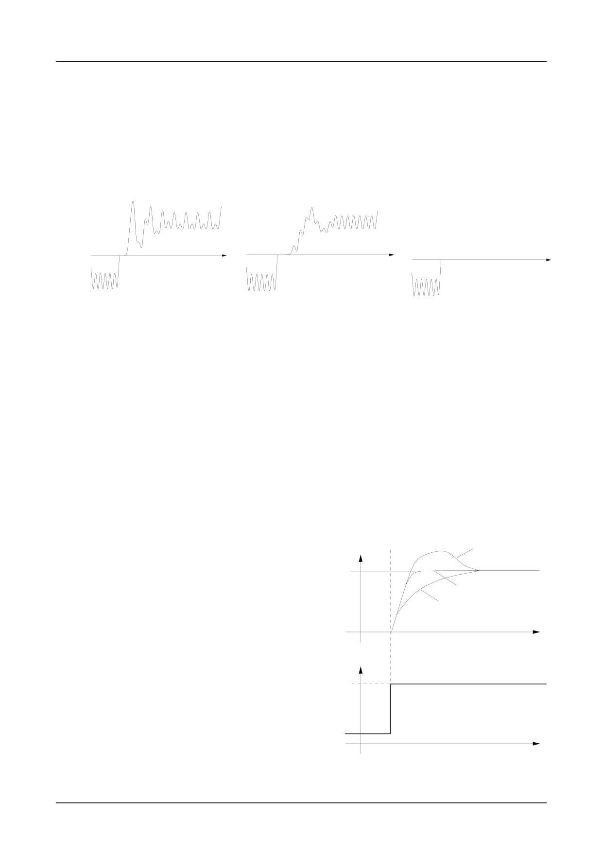
Setting up & Commissioning 4-8
change of Current Demand polarity the current should increase rapidly, but without overshoot
and then remain steady. If necessary adjust P6 and P7 slowly to obtain a Critically Damped
performance, i.e., the fastest response possible without overshoot, as shown in Figure 3.
Figures 1 and 2 show typical armature current waveforms where P6 and P7 are incorrectly set
and indicate the adjustment required to improve the drive performance to conform with that of
Figure 3.
In general, clockwise rotation of the presets will improve the speed of response, but rotating
the controls too far will tend to introduce overshoot.
FIGURE 1.
FIGURE 2.
FIGURE 3.
ARMATURE CURRENT WAVEFORM:
ARMATURE CURRENT WAVEFORM:
ARMATURE CURRENT WAVEFORM:
Current Loop controls incorrectly set.
Current Loop controls incorrectly set.
Current Loop Response (P6 and P7)
Integral Time Constant too short -
Proportional Gain too low - increase
correctly adjusted.
increase Current Loop Integral Time
Current Loop Proportional Gain by
Constant by rotating P7 anticlockwise.
rotating P6 clockwise.
5.
When the Current Loop response adjustment is completed, switch off the drive and disconnect
all supplies.
Reconnect the field wires to terminals F+ and F- ensuring that they are replaced in their
original positions i.e., with correct polarity. Remove any mechanical devices previously used
to lock the motor shaft.
Speed Loop Adjustment (P3 and P4)
1.
If the Speed Setpoint is applied via the setpoint ramp turn P1 and P2 fully clockwise
minimum ramp time. Set the Speed Setpoint to zero. Switch the Diagnostic Unit to position
16 so that the Oscilloscope displays the scaled Tacho Feedback signal (± 2.7v = ± 100%).
2.
Reconnect the supplies switch on and
(a) Under Damped
initiate “Run”. Apply a small set
change (about 20%) to the Speed
X %
Setpoint input and observe the speed
(c) Critically Damped
SPEED
response. If necessary adjust the Speed
FEEDBACK
(b) Over Damped
Proportional and Speed Integral presets
(Diagnostic 16)
(P3 and P4) gradually to obtain a
Critically Damped performance, i.e.,
TIME
the fastest response possible without
overshoot, as shown in Figure 4, Curve
(c). In general, clockwise rotation of
X %
the presets will improve the rate of
SPEED
response, but advancing the controls
SETPOINT
too far will tend to introduce overshoot.
(Diagnostic 15)
The optimum setting of P3 and P4 will
be a compromise between the two
TIME
extremes shown in Curves (a) and (b),
Figure 4.
FIGURE 4. TYPICAL SPEED RESPONSE CURVES
514C Product Manual
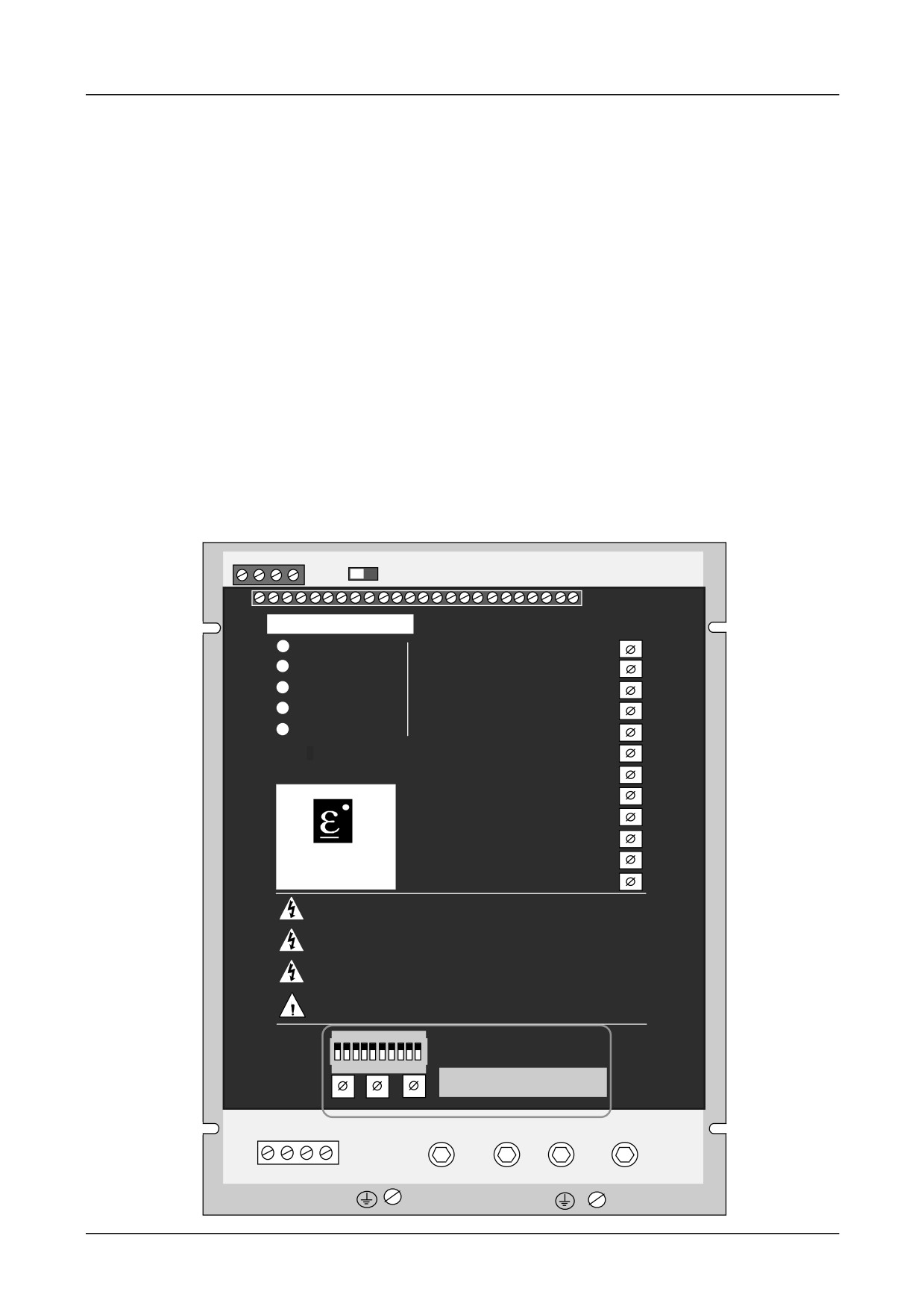
5-1 Diagnostics and Fault Finding
Chapter 5 Diagnostics and Fault Finding
DIAGNOSTIC LEDS
LED1 POWER ON
Illuminated when the Auxiliary Supply is energised.
LED2 STALL TRIP
Illuminated when the Controller has detected a Stall or
Current Limit Condition for more than 60 seconds.
LED3 OVERCURRENT Illuminated when the Armature Current exceeds
approximately 3½ times Calibrated Current.
LED4 PLL LOCK
Illuminated when the Main AC Supply is energised
and the Electronic Phase Lock Loop is Synchronised.
LED5 CURRENT LIMIT Illuminated when the Controller is in Current Limit and
Speed Control is lost, i.e. a stall condition, after 60
seconds the controller will trip.
A1 A2 A3 A4
DIAGNOSTIC LEDS
L1 POWER ON
RAMP UP
P1
L2 STALL TRIP
RAMP DOWN
P2
L3 OVERCURRENT
SPEED PROPORTIONAL
P3
L4 PLL LOCK
P4
SPEED INTEGRAL
L5 CURRENT LIMIT
CURRENT LIMIT
P5
CURRENT PROPORTIOP6
514C
CURRENT INTEGRAL P7
IR COMPENSATION
P8
P9
MAX SPEED CALIBRATIP1
0
EUROTHERM
P11
ZERO SPEED ADJUST
DRIVES
ZERO SPEED THRESHOP
12
CAUTION
Before Switching ON Refer to the Manual for Installation and Safety,
Switch and Transformer Setting Information.
CAUTION
Risk of Electric Shock - More than One Disconnect Switch may be Required
to De-energise the Equipment Before Servicing
AVERTISSEMENT
Risque de decharge electrique. La coupure de plusieurs interrupteurs pout
etre necessaire avant utilisation - voir le schema
CAUTION
Compatible with Type B RCD Protection Devices Only
SW1
ON
1 2 3 4 5 6 7 8 9 10
SW2
SW3
SW4
FL1 FL2 F- F+
L2/N
L1
A+
A-
514C Product Manual

Diagnostics and Fault Finding
5-2
DRIVE TRIPS
When a fault occurs the drive will trip and display the cause of the trip on the indicator LEDs
or on the diagnostic (test point 6) for the Thermistor/Microtherm Trip.
The Stall Trip (LED2 on) and the Thermistor/Microtherm Trip are reset by re-applying the
run signal to Terminal 5. The drive will then re-start. (It is necessary to remove then re-apply
the run signal.)
An Overcurrent (LED3 on) is not reset by the Run signal re-application as this trip can
indicate that a major fault has occurred. The overcurrent trip is reset by removing then re-
applying the auxiliary supply. Remove the Run signal before removing the auxiliary supply.
Resetting the Stall Trip does not reset the drive’s internal timer that caused the trip. If the
drive is operated in current limit (LED5 illuminated) immediately after a Stall Trip the trip
could re-occur. This protects the drive and the motor from continuous overload operation.
However, it is possible to prevent the stall trip by using the Stall Override (Terminal 15)
DIAGNOSTIC TEST POINT DESCRIPTIONS
Test
Description
Condition
Voltage
Node
1
Internal +15V Supply
Auxiliary Supply On
+15V ±0.15V
2
External +10V Supply
Auxiliary Supply On
+10V ±0.025V
3
External -10V Supply
Auxiliary Supply On
-10V ±0.025V
4
Internal -15V Supply
Auxiliary Supply On
-15V ±0.15V
5
Drive Enable
Enable
+10V to +24V
Terminal T20
Inhibit
0V
6
Motor Microtherm
Normal
+12V to +15V
/Thermistor
Overtemperature
0V to 2V
7
At Zero Setpoint
At Zero Setpoint
+13V±2V
Above Zero Setpoint
0V
8
At Zero Speed
At Zero Speed
+13V±2V
Above Zero Speed
0V
9
Run
Run
+24V±4V
Terminal T5
Inhibit
0V
10
Health
Healthy
+24V±4V
Terminal T19
Unhealthy
0V
11
Setpoint Ramp Input
100% Forward Speed
+10V
Terminal T13
Zero Speed
0V
100% Reverse Speed
-10V
12
Positive Trim Setpoint
100% Forward Speed
+10V
Terminal T10
Zero Speed
0V
100% Reverse Speed
-10V
13
Inverted Setpoint Sum
100% Forward Speed
-10V
Terminal T21
Zero Speed
0V
100% Reverse Speed
+10V
14
Negative Trim Setpoint
100% Forward Speed
-10V
Terminal T17
Zero Speed
0V
100% Reverse Speed
+10V
514C Product Manual

5-3 Diagnostics and Fault Finding
Test
Condition
Voltage
Description
Node
15
Total Setpoint Sum
100% Forward Speed
+10V
Terminal T12
Zero Speed
0V
100% Reverse Speed
-10V
16
Speed Feedback
100% Forward Speed
-2.7V
Zero Speed
0V
100% Reverse Speed
+2.7V
17
Speed Error
Run Steady State
Approx. 0V plus Ripple
Run Transient
up to ±10V
Stopped Zero Setpoint
0V
Stopped +ve Setpoint
up to -10V
Stopped -ve Setpoint
up to +10V
18
Current Demand
Run Steady State
up to ± 10V
Stopped or Disabled
0V
19
Speed Loop Out
Run Steady State
up to ± 10V
Stopped or Disabled
0V
20
No Connection
21
No Connection
22
No Connection
23
Current Limit Terminal
Open Circuit -110%
+5.5V
Terminal T7
7.5V or greater -
+7.5V
150%.
24
Main Current Limit
T7 = 7.5V or greater.
P5 Maximum.
150% Current
+7.5V
P5 Minimum.
0.5% Current
+0.025V
25
Total Current Demand
Run Transient
up to ±7.5V
(Terminal T7
Positive Bridge at
+7.5V
7.5V or greater -150%.)
150% Limit.
Negative Bridge at
-7.5V
150% Limit.
26
Current Feedback
Positive Bridge at
+1.1V
100%
Negative Bridge at
-1.1V
100%
27
Phase Angle
Running
±10V
100% Forward Speed.
approx +10V
100% Reverse Speed.
approx -10V
Zero Speed
approx 0V
514C Product Manual

Diagnostics and Fault Finding
5-4
TROUBLESHOOTING
PROBLEM
POSSIBLE CAUSE
REMEDY
"Power On" LED 1
No Auxiliary Supply
Check Auxiliary Supply Availability. Is
Not Illuminated
Available.
the Supply Fuse fitted or the Circuit
Breaker closed?
Auxiliary Supply Fuse.
Supply fuse Blown. Investigate
Contactor connections or Transformer
Tapping Switch position.
Incorrect Supply Voltage
Check that the Supply Voltage is
Applied to Controller.
compatible with the Transformer
Tapping Switch position.
Illuminated but drive
Incorrect Auxiliary Supply
Correct Auxiliary Supply Switch Setting.
does not operate.
Switch Setting.
Controller “Trips”
Microtherm not wired.
Connect Microtherm to terminals T22
Immediately after
and T11 or if Microtherm not available
Drive Run command.
link T22 to T11.
“PLL LOCK” LED 4
Main Power Supply not
1) Main Contactor not Energised.
not illuminated after
present.
Check Run Command & Contactor
Drive Run command.
wiring.
2) Is the Supply Fuse fitted or the
Circuit Breaker closed?
Motor will not turn
Enable Signal not
Check Control Circuit Wiring.
after Drive Run
present.
Command.
No Speed Setpoint.
Check Total Setpoint terminal T12.
Check Setpoint Pot'meter & Wiring.
If using the Setpoint Ramp Input T13
check SW1/6 is OFF.
No Armature Current.
Check P5 adjustment & External
Current Limit Potentiometer setting &
wiring (if used).
No Field.
Check Field AC Supply and Field
connections.
Motor Jammed.
Free Obstruction.
Motor Runs with
Incorrect Current Limit
Check P5 setting.
“Current Limit”
Setting.
Check External Current limit setting &
LED5 illuminated
wiring if used.
and Stops after short
Incorrect Current
Check Current Calibration Switches
period with "Stall"
Calibration.
SW2, 3 & 4.
LED2 Illuminated
Motor Jammed.
Free Obstruction.
Motor Runs and
Maximum Controller
Check compatibility of Motor Voltage
Stops after short
Output Exceeded
to Controller Output Voltage.
period with "Stall"
Incorrect Feedback
Check Feedback Voltage Calibration
LED2 Illuminated
Voltage Calibration
Switches SW1/1 & SW1/2. Note these
Switches must be set for both
Tachogenerator & Armature Voltage
Feedback.
Faulty Tachogenerator
Check Tachogenerator (use Armature
and/or Coupling.
Voltage Feedback Temporarily).
514C Product Manual

5-5 Diagnostics and Fault Finding
PROBLEM
POSSIBLE CAUSE
REMEDY
Motor Runs but stops
Overcurrent.
Check Motor wiring and Motor for
after a period with
earth faults.
"Overcurrent Trip"
Check controller for Faulty Thyristor
LED 3 Illuminated.
Devices.
Motor Runs but stops
Motor Overtemperature
Check cooling Fan if used. Fan
after a period
trip from Motor
rotation may be reversed giving airflow
indicating Controller
Microtherm.
but insufficient for adequate cooling.
Unhealthy.
Check Cooling path.
Motor runs at Full
Tachogenerator
Check Tachogenerator viability and
Speed only
Feedback. Incorrect
connectivity.
Tachogenerator Polarity
Check Speed Feedback Calibration
or Open Circuit
Switches.
Tachogenerator
Check Max Speed Calibrate
Potentiometer P10.
Armature Voltage
Check Speed Feedback Calibration
Feedback.
Switches.
Check Max Speed Calibrate
Potentiometer P10.
Open Circuit Speed
Check Terminal 13 or 10 as
Setpoint Potentiometer
appropriate
Motor runs with Zero
Zero Speed Offset
Adjust P11 to give Zero Speed
Setpoint.
Adjustment
Motor Speed
Stability Adjustment.
See General Running performance
unstable at Constant
adjustments Chapter 4.
Speed Setpoint.
Current Stability
Adjust Current Loop Stability
Potentiometers P6 & P7.
Speed Stability
Adjust Speed Loop Stability
Potentiometers P3 & P4.
IR Compensation.
No IR compensation for
Tachogenerator Feedback. Reduce P8
for Armature Voltage Feedback
Drive does not
Drive incorrectly
Set SW2, SW3, SW4 to correct
produce required
calibrated.
calibration current.
current.
Current calibration set
The maximum current that the drive
incorrectly.
can produce is its rated current.
Setting the calibration above this can
cause damage.
Settings above 39.9Amps will cause
erroneous calibration values.
DO NOT CALIBRATE THE DRIVE
ABOVE RATED CURRENT.
Current Limit set wrongly.
Check the current limit diagnostic 23
and the main current limit diagnostic
24. Adjust P5 and external current
limit pot (if used).
514C Product Manual

Service and Repair
6-1
Chapter 6 Service and Repair
The product has no user serviceable parts and should be returned to SSD Drives for repair.
The product should be returned in the original packaging if possible or else reasonable care
should be taken in the packing of the product to ensure that no transport damage be incurred.
Technical Support can be obtained by contacting SSD Drives at the address given or your
local supplier.
DISPOSAL
This product contains materials which are consignable waste under the Special Waste
Regulations 1996 which complies with the EC Hazardous Waste Directive - Directive
91/689/EEC.
We recommend you dispose of the appropriate materials in accordance with the valid
environmental control laws. The following table shows which materials can be recycled and
which have to be disposed of in a special way.
Matrial
Recycle
Disposal
metal
yes
no
plastics material
yes
no
printed circuit board
no
yes
The printed circuit board should be disposed of in one of two ways:
1. High temperature incineration (minimum temperature 1200oC) by an incinerator
authorised under parts A or B of the Environmental Protection Act.
2. Disposal in an engineered land fill site that is licensed to take aluminium electrolytic
capacitors. Do not dispose of in a land fill site set aside for domestic waste.
Packaging
During transport our products are protected by suitable packaging. This is entirely
environemntally compatible and should be taken for central disposal as secondary raw
material.
514C Product Manual
ISS.
MODIFICATION
ECN No.
DATE
DRAWN
CHK'D
514C Product Manual.
Sheet 1 filed in drawing office.
4
Added to Product Identification diagram
“Auxiliary Supply Selector Switch”.
Page 3-3 Added to Recommendations,
“Unused Analogue ... interference”.
Page 4-4 Added to Power-Up, v), “Note ...
switch”.
Page 4-6 Added to 15. “Note ... change.”
Page 5-4 Added to Troubleshooting
“Illuminated but Drive does not operate”.
12307
15.4.98
FEP
GDR
5
Page 1-4 New CE EMC Declarations.
13908
15.1.01
FEP
CM
Pages 1-8 changed Terminal Tightening
13831
Torque from 0.6 Nm to 0.45 and 4.5 lbf-in to
4.0.
0.6 Nm to 0.5 and added (UL open-type).
Page 1-11 Added “Overvoltage”.
“
Page 3-4 changed Terminal tightening Torque
“
Control settings from 0.6 to 0.45, 0.4 to 0.33,
4.5 to 4.0 and Auxiliary settings from 0.6 to
0.5 and 0.4 to 0.375.
Page 3-5 Re-written for UL Compliance
“
Page 6-1 Added Disposal information.
Address list added to back cover.
13164
6
New Certificates.
19887
5.7.07
CM
GDR
Company name change and new Safety
(19591)
Information
FIRST USED ON
MODIFICATION RECORD
514C Product Manual
SHT. 2
DRAWING NUMBER
OF 2
ZZ463296