Parker 404LXR Series Product Manual (2003)
Manual No. 100-5319-01
Daedal
Rev. 3
404LXR Series
Product Manual
Effective: April 11, 2003
Supersedes:
Electromechanical
Positioning Systems
Automation
404LXR Series Product Manual
Important User Information
The information in the product manual, including any apparatus, methods, techniques, and concepts
described herein, are the proprietary property of Parker Hannifin Corporation, Daedal Division or its
licensors, and may not be copied, disclosed, or used for any purpose not expressly authorized by the
owner thereof.
Since Parker Hannifin Corporation, Daedal Division constantly strives to improve all of its products, we
reserve the right to change this product manual and equipment mentioned therein at any time without
notice.
For assistance contact:
Parker Hannifin Corporation
Daedal Division
1140 Sandy Hill Road
Irwin, PA 15642
Phone: 724/861-8200
800/245-6903
Fax:
724/861-3330
E-mail: ddlcat@parker.com
Web site: www.daedalpositioning.com
2
404LXR Series Product Manual
404LXR Series Product Manual
Table of Contents
REVISION NOTES
4
CHAPTER 1 - INTRODUCTION
5
PRODUCT DESCRIPTION
5
UNPACKING
5
RETURN INFORMATION
6
REPAIR INFORMATION
6
WARNINGS AND PRECAUTIONS
6
SPECIFICATION CONDITIONS AND CONVERSIONS
7
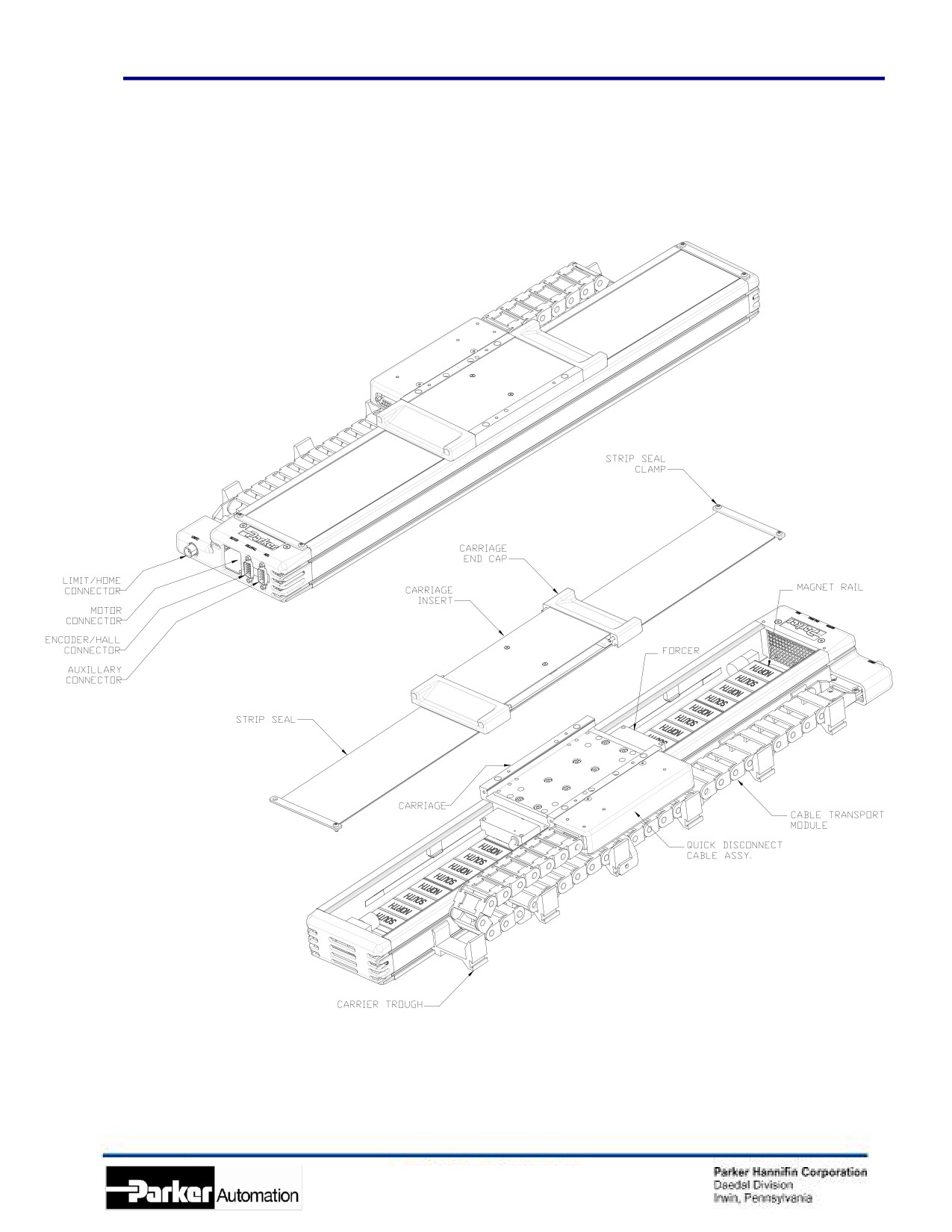
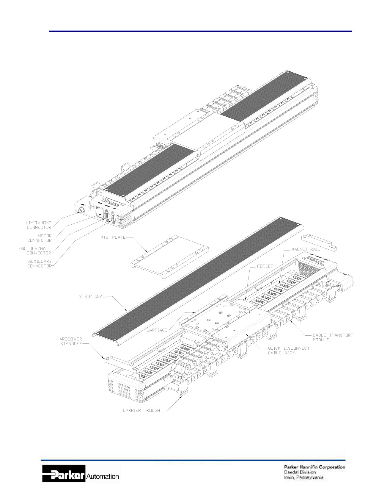
ASSEMBLY DIAGRAMS
8
Strip Seal Version
8
Hardcover Version
9
CHAPTER 2 - 404LXR SERIES TABLE SPECIFICATIONS
10
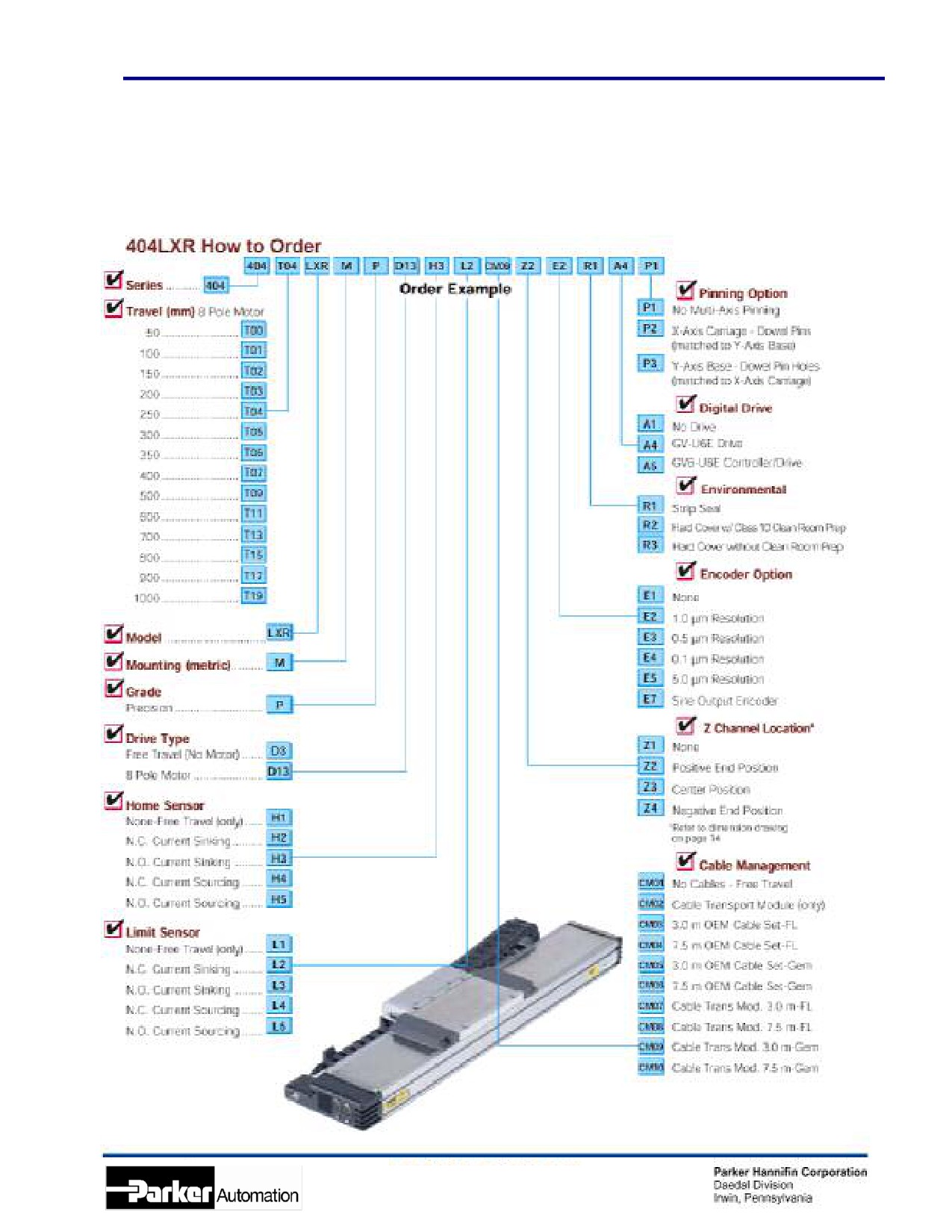
ORDER NUMBER NOMENCLATURE
10
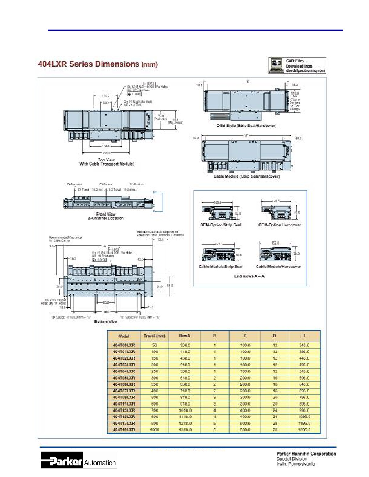
DIMENSIONAL DRAWINGS
11
GENERAL TABLE SPECIFICATIONS
12
404LXR SERIES TECHNICAL DATA
17
Force/Speed Charts
17
Clean Room Preparation
18
ELECTRICAL SPECIFICATIONS
19
CABLING AND WIRING DIAGRAMS
21
Connector Pin Out and Extension Cable Wire Color Codes
21
CHAPTER 3 - HOW TO USE THE 404LXR
24
MOUNTING SURFACE REQUIREMENTS
24
MOUNTING METHODS
24
SIDE AND INVERTED MOUNTING CONCERNS
25
SETTING TRAVEL LIMIT SENSORS
25
SETTING HOME SENSOR
26
Z CHANNEL POSITION REFERENCE
26
GROUNDING / SHIELDING
26
CABLING
27
CHAPTER 4 - PERFORMANCE
28
ACCELERATION LIMITS
28
SPEED LIMITS
29
ENCODER ACCURACY AND SLOPE CORRECTION
29
THERMAL EFFECTS ON ACCURACY
31
THERMAL EFFECTS ON REPEATABILITY
32
CAUSES OF TEMPERATURE INCREASES
32
COMPENSATING FOR THERMAL EFFECTS
33
CHAPTER 5 - CONNECTING THE GEMINI AMPLIFIER
34
CHAPTER 6 - MAINTENANCE AND LUBRICATION
37
INTERNAL ACCESS PROCEDURE
37
SQUARE RAIL BEARING LUBRICATION
39
CABLE MANAGEMENT MODULE REPLACEMENT
39
LIMIT AND HOME SENSOR MODULE ADJUSTMENT
41
LIMIT AND HOME SENSOR MODULE REPLACEMENT
42
APPENDIX A - UNDERSTANDING LINEAR MOTORS
43
THE LINEAR MOTOR CONCEPT
43
LINEAR MOTOR BENEFITS
43
SLOTLESS LINEAR MOTOR DESIGN
43
ADVANTAGES/DISADVANTAGES OF SLOTLESS LINEAR MOTORS
44
APPENDIX B - INTERNAL PROTECTION
45
INDEX
47
3
404LXR Series Product Manual
Revision Notes
Revision Notes
Rev 3 April 11, 2003
Correction for Motor Wire 4 Pin Mat-N-Lok - p. 21
Limit and Home Sensor Module Adjustment Switch positions corrected. - p. 41
4
404LXR Series Product Manual
Chapter 1 - Introduction
Chapter 1 - Introduction
Product Description
404LXR Positioner
The 404LXR is a slotless, brushless linear servo motor/square rail bearing positioner housed within
a high strength, extruded aluminum body with magnetically retained protective seals. The
positioner is powered by a single rail of high energy rare earth magnets. Load bearing members
provide heavy load and moment capacity, dynamic stiffness and precise straightness and flatness
of travel. The positioner’s integral linear encoder provides high precision, non-contact positional
feedback with selectable resolutions from 0.1 to 5.0 microns. The positioner is also offered with
inductive proximity limit & home sensors, a “Quick Connect”, extended life, and a cable transport
system.
Unpacking
Unpacking
Carefully remove the positioner from the shipping crate and inspect the unit for any evidence of
shipping damage. Report any damage immediately to your local authorized distributor. Please save
the shipping crate for damage inspection or future transportation.
Incorrect handling of the positioner may adversely affect the performance of the unit in its
application. Please observe the following guidelines for handling and mounting of your new
positioner.
•
DO NOT allow the positioner to drop onto the mounting surface. Dropping the positioner can generate
impact loads that may result in flat spots on bearing surfaces or misalignment of drive components.
•
DO NOT drill holes into the positioner. Drilling holes into the positioner can generate particles and
machining forces that may effect the operation of the positioner. Daedal will drill holes if necessary;
contact your local authorized distributor.
•
DO NOT subject the unit to impact loads such as hammering, riveting, etc. Impacts loads generated by
hammering or riveting may result in flat spots on bearing surfaces or misalignment of drive components.
•
DO NOT lift the positioner by cables or cable management system. Lifting postioner by cables or cable
management system may effect electrical connections and/or cable management assembly. The unit
should be lifted by the base structure only.
•
DO NOT push in magnetically retained strip seals when removing positioner from shipping crate.
Damaging strip seals may create additional friction during travel and may jeopardize the ability of the
strip seals to protect the interior of the positioner.
•
DO NOT submerge the positioner in liquids.
•
DO NOT disassemble positioner. Unauthorized adjustments may alter the positioner’s specifications and
void the product warranty.
5
404LXR Series Product Manual
Chapter 1 - Introduction
Return Information
Returns
All returns must reference a “Return Material Authorization”, (RMA), number. Please call your local
authorized distributor or Daedal Customer Service Department at 800-245-6903 to obtain a “RMA”
number. See Daedal Catalog #8080/USA, page D34, for additional information on returns and
warranty.
Repair Information
Out-of-Warranty Repair
Our Customer Service Department repairs Out-of-Warranty products. All returns must reference a
“RMA” number. Please call your local authorized distributor or Daedal Customer Service
Department at 800-245-6903 to obtain a “RMA” number. You will be notified of any cost prior to
making the repair.
Warnings and Precautions
Hot Surfaces
DO NOT touch ‘carriage forcer’, (see page 7, Assembly Diagram, for component location), after
high duty operation. Unit may be too HOT to handle.
Electrical Shock
DO NOT take apart or touch any internal components of the positioner while unit is plugged into an
electrical outlet. SHUT OFF power before replacing components to avoid electrical shock.
High Magnetic Field
Unit may be HAZARDOUS to people with Pace Makers or any other 'magnetically-sensitive'
medical devices. Unit may have an effect on 'magnetically-sensitive' applications.
Ferrous Materials
The positioner's 'protective seals' MAY NOT keep out all small ferrous materials in applications with
air born metallic particles. The customer must take additional precautions in these applications to
keep positioner free of these highly magnetic particles.
Vertical Operation
The 404LXR is NOT recommended for vertical operation. The carriage and customer's load will fall
in power loss situations potentially causing product damage or personal injury.
General Safety
Because linear motors can accelerate up to 5 g's, and sometimes positioners move without
warning, keep all personnel away form dynamic travel range of positioner.
6
404LXR Series Product Manual
Chapter 1 - Introduction
Specification Conditions and Conversions
Specifications are Temperature Dependent
Catalog specifications are obtained and measured at 20 Degrees C. Specifications at any other
temperature may deviate from catalog specifications. Minimum to maximum continuous operating
temperature range (with NO guarantee of any specification except motion) of a standard unit before
failure is 5 - 40 Degrees C.
Specifications are Mounting Surface Dependent
Catalog specifications are obtained and measured when the positioner is fully supported, bolted
down (to eliminate any extrusion deviation), and is mounted to a work surface that has a maximum
flatness error of 0.013mm/300mm (0.0005”/ft).
Specifications are Point of Measurement Dependent
Catalog specifications and specifications in this manual are measured from the center of the
carriage, 38 mm above the carriage surface. All measurements taken at any other location may
deviate from these values.
7
404LXR Series Product Manual
Chapter 1 - Introduction
Assembly Diagrams
Strip Seal Version
8
404LXR Series Product Manual
Chapter 1 - Introduction
Hardcover Version
9
404LXR Series Product Manual
Chapter 2 - 404LXR Series Table Specifications
Chapter 2 - 404LXR Series Table Specifications
Order Number Nomenclature
10
404LXR Series Product Manual
Chapter 2 - 404LXR Series Table Specifications
Dimensional Drawings
11
404LXR Series Product Manual
Chapter 2 - 404LXR Series Table Specifications
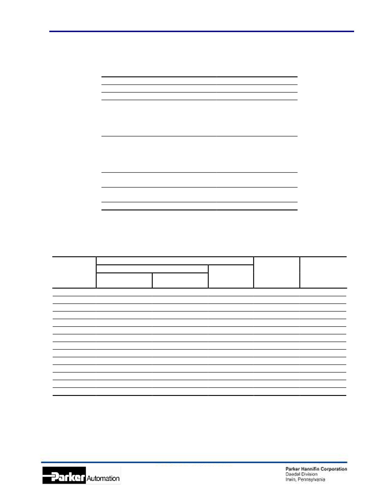
General Table Specifications
Specifications
Motor Model
8 Pole
Rated Load
45 kg
Maximum Acceleration
5 Gs
Maximum Velocity
Resolution: 0.1 um
0.3 m/sec
0.5 um
1.5 m/sec
1.0 um
3.0 m/sec
5.0 um
3.0 m/sec
Positional Repeatability
Resolution: 0.1 um
+/- 1.0 um
0.5 um
+/- 1.0 um
1.0 um
+/- 2.0 um
5.0 um
+/- 10.0 um
Maximum Force (Peak)
180 N
40 lb.
Maximum Force (Continuous)
50 N
11 lb.
Carriage Weight
1.4 kg
Travel Dependent Specifications
Accuracy*
Strip Seal
Hard Cover
Travel
Positional
Straightline
Version Unit
Version Unit
(mm)
Accuracy*
0.1, 0.5, 1.0
5.0 resolution
Weight (kg)
Weight (kg)
resolution (um)
(um)
(um)
50
6
16
6
4.4
4.4
100
7
17
7
4.8
4.9
150
8
18
9
5.2
5.4
200
10
20
11
5.6
5.8
250
12
22
14
6.0
6.3
300
14
24
17
6.4
6.7
350
16
26
19
6.8
7.2
400
18
28
22
7.2
7.6
500
21
31
26
8.0
8.6
600
25
35
31
8.9
9.5
700
28
38
35
9.7
10.5
800
31
41
39
10.6
11.4
900
33
44
43
11.5
12.5
1000
35
45
47
12.4
13.6
* Accuracy stated is at 20 degrees C, utilizing slope correction factor provided.
12
404LXR Series Product Manual
Chapter 2 - 404LXR Series Table Specifications
404LXR Series Technical Data
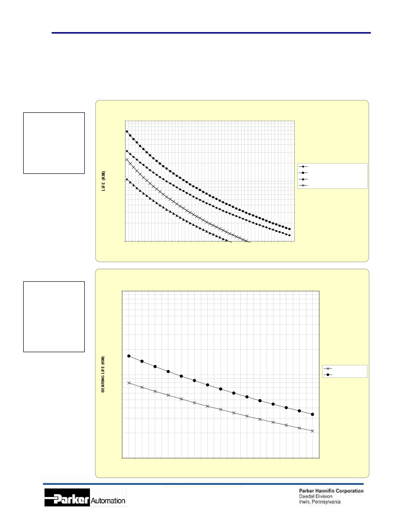
The useful life of a linear table at full catalog specifications is dependent on the forces acting upon it. These forces include both
static components resulting from payload weight, and dynamic components due to acceleration/deceleration of the load. In
multi-axes applications, the primary positioner at the bottom of the stack usually establishes the load limits for the combined
axes. When determining load/life, it is critical to include the weight of all positioning elements that contribute to the load
supported by the primary axis. The life/load charts are used to establish the table life relative to the applied loads.
404LXR CARRIAGE LIFE VS LOAD
Table Load Chart
100000
The “Table Load” chart is
intended to provide a rough-
cut evaluation “life/load”
characteristics of the carriage
support bearings. This curve
is based on the applied load
being centered on the
carriage, normal to the
carriage mounting surface.
NORMAL LOAD CONTINOUS 55 (N)
NORMAL LOAD CONTINUOS 28(N)
SIDE LOAD CONTINUOS 55(N)
10000
SIDE LOAD CONTINUOUS 28(N)
1000
1
3
5
7
9 11 13 15 17 19 21 23 25 28 30 32 34 36 38 40 42 44 46 48 50
LOAD (KG)
BEARING LIFE NORM AL LOAD
Bearing Load Chart
100000
The “Bearing Load” chart
is to be used in conjunction
with the corresponding
formulas on the following
pages to establish the life/load
for each bearing (4 per table).
Several dimensions and the
load geometry are required
for these computations. The
dimensions are referenced
below.
55(N) CONTINOUS
10000
28 (N) CONTINUOS
1000
10
20
30
40
50
60
70
80
90
100
110
120
130
140
150
NORMAL LOAD PER BEARING (N)
13
404LXR Series Product Manual
Chapter 2 - 404LXR Series Table Specifications
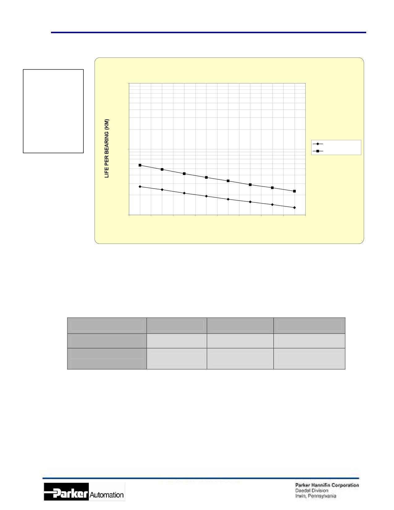
BEARING LIFE SIDE LOAD
Side Bearing Load
Chart
100000
The “Side Bearing Load”
chart is to be used in
conjunction with the
corresponding formulas on
the following pages to
establish the life/load for each
bearing (4 per table). Several
dimensions and the load
geometry are required for
these computations. The
dimensions are referenced
55(N) CONTINUOS"
below.
10000
28(N) CONTINOUS
1000
10
20
30
40
50
60
70
80
SIDE LOAD PER BEARING (N)
Note: 55 (N) continuous is the life rating if the table is operated with a motor thrust force of 55 Newtons
(RMS). The reason that continuous motor force effects bearing life is due to forces applied to the bearing
caused by thermal expansion of the carriage. The 28 (N) rating is the life if only 28 Newtons (RMS) is used.
d1
d2
da
Strip Seal Model
108.5
60.0
48.5
Hardcover
108.5
60.0
53.5
Model
14
404LXR Series Product Manual
Chapter 2 - 404LXR Series Table Specifications
15
404LXR Series Product Manual
Chapter 2 - 404LXR Series Table Specifications
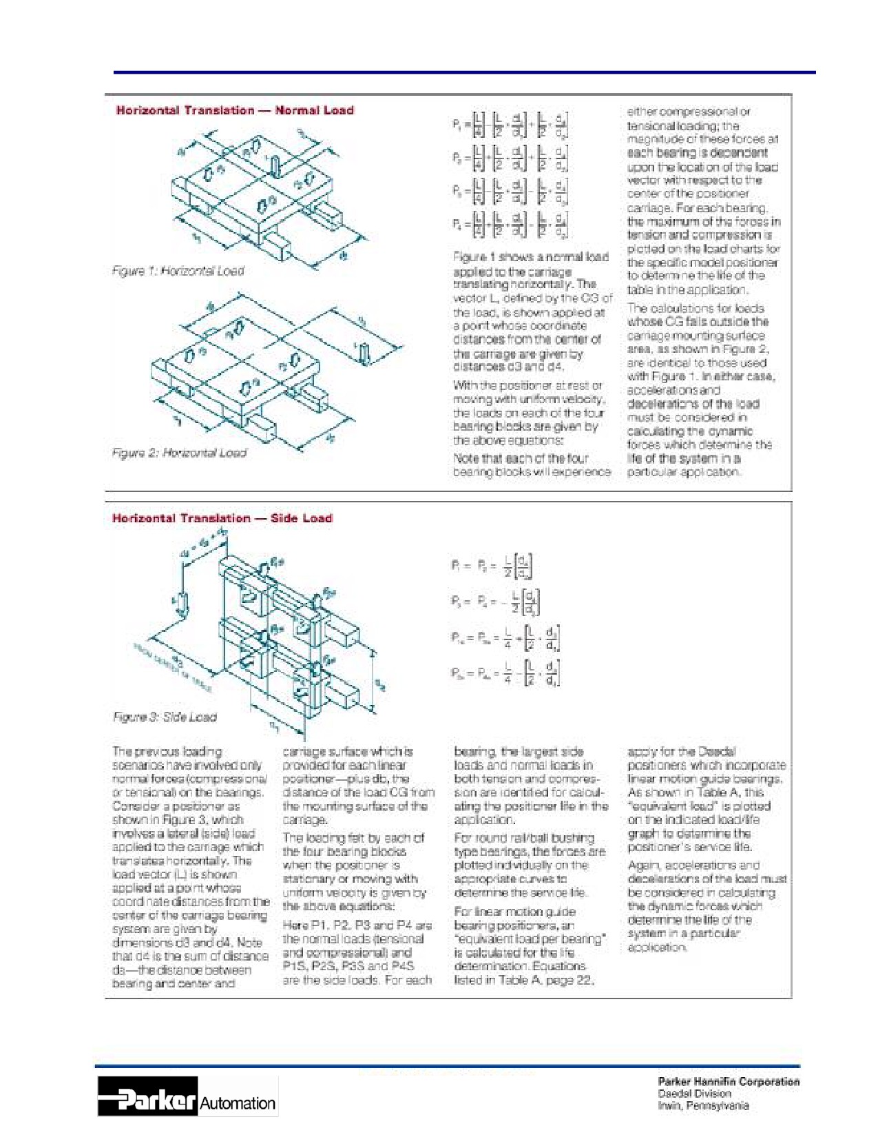
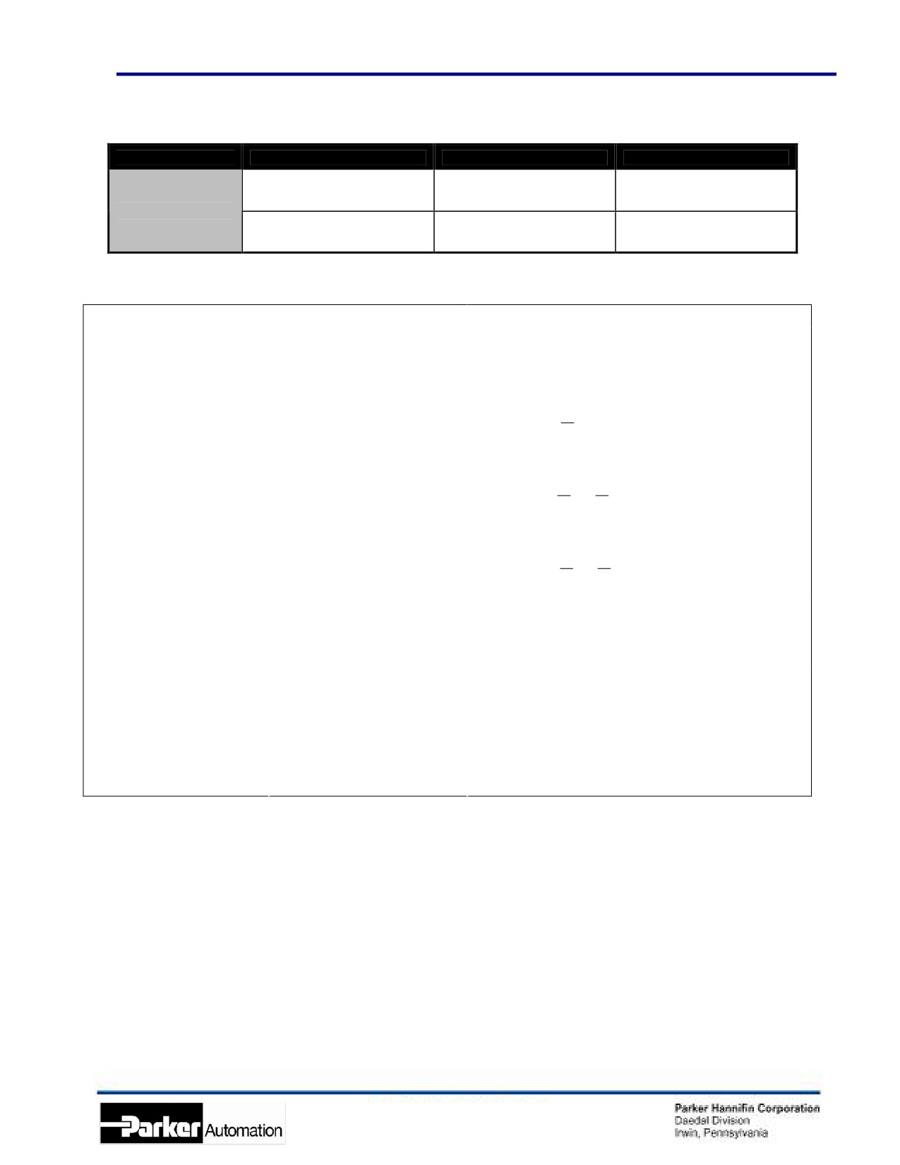
Table A - Linear Motion Guide Bearing Life/Load Computation
Positioner
Loads
Compute
Evaluate Life On
Side & tension Ps > Pt
Pe = (0.5 x Pt) + Ps
Side load chart
Side & tension Ps Pt
Pe = (0.5 x Ps) + Pt
Tension chart
404LXR
Side & compression Ps > Pc
Pe = (0.5 x Pc) + Ps
Side load chart
Side & compression Ps Pc
Pe = (0.5 x Ps) + Pc
Compression chart
Example Computations
Example 1
Page 14 shows this
4
configuration with dimensions
P
P
= L d
=1
(tension) Kgf
1 =
2
Horizontal Translation
given here.
2
d
2
with Side Loads, 404LXR-
8 Pole Positioner
d1 = 108.5 mm
L
d
4
P
=
P
=
=
1
(compression) Kgf
3
4
L = 10 Kgf
db = 130 mm
2
d
2
130 mm from
carriage surface;
d2 = 60.0 mm
L
L
d
50 mm from carriage
3
P
=
P
=
+
=
1s
3s
center.
d3 = 50 mm
4
2
d
1
da = 48.5 mm
L
L
d
3
P
=
P
=
=
d4 = da + db = 178.5
2s
4s
4
2
d
1
The normal and side force
Life for each bearing needs to be evaluated
components on each bearing
independently. For bearings with a side load,
block are computed from the
refer to the combined equivalent loading factors
equations as shown:
(Table A above).
Example:
Bearing 3 had P3 = 5.6 Kgf tension and P3s = 2.7
Kgf side load
Ps Pc Pe = (0.5 × Ps) + Pc = 7Kgf
Refer to Bearing Life Normal Load (page 12)
Life @ 7 Kgf (69 Newtons) = 4200 km
16
404LXR Series Product Manual
Chapter 2 - 404LXR Series Table Specifications
404LXR Series Technical Data
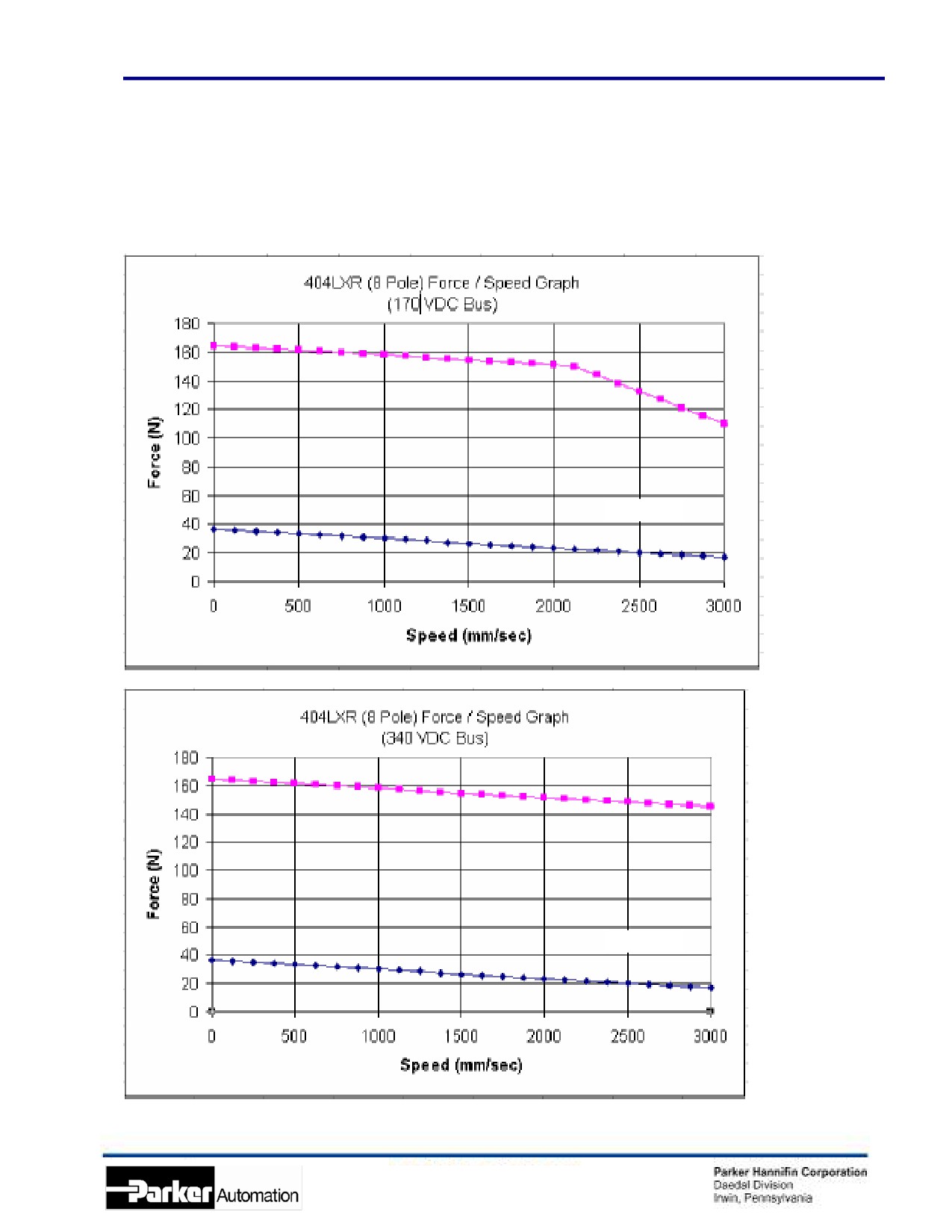
Force/Speed Charts
The chart on this page illustrates the characteristics of the 404LXR linear motor. The force/speed chart
shows the characteristics of the motor with either a 170 VDC or 340 VDC bus voltage.
Peak
Continuous
Peak
Continuous
17
404LXR Series Product Manual
Chapter 2 - 404LXR Series Table Specifications
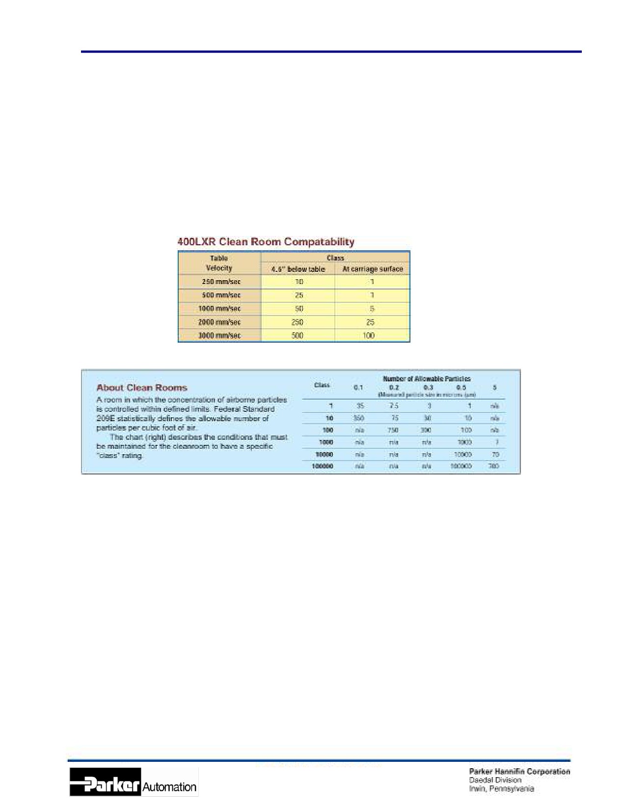
Clean Room Preparation
404LXR tables with clean room preparation were tested in Daedal’s vertical laminar flow work station which
utilizes ULPA filters to produce an environment having a cleanliness of class 1 prior to testing. Tables were
tested in a variety of orientations with sampling both below the table and at the carriage mounting surface.
Laminar flow rate is 0.65 inches W.C.
Standard Clean Room Preparation
Stringent cleaning and handling measures
Clean room rated lubricant
Strip seal replaced with hard shell cover
18
404LXR Series Product Manual
Chapter 2 - 404LXR Series Table Specifications
Electrical Specifications
Parameter
8 Pole
Units
Continuous Force 1
50
N
Continuous Current 1,4,8
2.3
Amps Peak
Continuous Current 1,7
2.0
Amps DC
Peak Force 6
180
N
Peak Current 4,6,8
8.3
Amps Peak
Peak Current 6,7
7.2
Amps DC
Voltage Constant 3,4
25.15
Volt/m/sec
Force Constant 9
21.78
N/Amps Peak
Force Constant 3,4
25.15
N/Amps DC
Resistance 3
10.2
Ohms
Inductance 5
2.63
mH
Maximum Bus Voltage
340
Volts DC
Thermal Resist. Winding-Ambient
1
C/watt
Viscous Damping
6.3
N/m/s
Static Friction 13
15
N
Intermit Force Duration 10
12
Seconds
Peak Force Duration 11
5
Seconds
Magnetic Attraction 2
280
N
Electrical Pitch 12
42
mm
Mass-Motor Carriage
1.5
Kg
Rated Winding Temp.
90
C/watt
Winding Class
H
-
1.
@ 25o C ambient, 90o C winding temperature
9.
Total motor force per peak of the sinusoidal amps measured in any phase,
2.
Measured with a 0.70 mm gap
+/-10%
3.
Measured line to line +/-10%
10.
Maximum time duration with 2 times rated current applied with initial winding
temperature at 60o C
4.
Value is measured peak of sine
11.
Maximum time duration with 3 times rated current applied with initial winding
5.
+/-30% line to line, inductance bridge measurement @1Khz
temperature at 60o C
6.
Initial winding temperature must be 60o C or less before peak current is
12.
The distance from the leading edge of the north pole to the leading edge of
applied
the next north pole
7.
DC current through a pair of motor phases of a trapezoidal (six state)
13.
Average friction over total table travel
commutated motor
8.
Peak of the sinusoidal current in any phase for a sinusoidal commutated
motor
Encoder Specifications
Description
Specification
Input Power
5 VDC +/-5% 150 mA
Output (Incremental)
Square wave differential line driver (EIA RS422) 2 channels A and B in
quadrature (90) phase shift.
Reference (Z Channel)
Synchronized pulse, duration equal to one resolution bit. Repeatability of
position is unidirectional moving toward positive direction.
Maximum Speed
5.0 micron resolution = 3.0 meters/sec
1.0 micron resolution = 3.0 meters/sec
0.5 micron resolution = 1.5 meters/sec
0.1 micron resolution = 0.3 meters/sec
Hall Effect Specification
Description
Specifications
Input Power
+5 to +24 VDC, 30 mA
Output
Open collector, Current Sinking, 20 mA Max
19
404LXR Series Product Manual
Chapter 2 - 404LXR Series Table Specifications
Gemini Drive Specifications
Description
Specification
Drive Input Power
Voltage
96-265 VAC
Phase
1Ø
Frequency
50/60 Hz
24V Keep Alive (Optional)
24 VDC - 20%
Drive Output Power
Bus Voltage
170 or 340 VDC
Switching Frequency
8 or 16 kHz
Continuous Current
4.5 Amps
Peak Current
11.25 Amps
Commutation
Sinusoidal
Command Inputs
Velocity and Torque
+/-10V
Position Mode
Step & Direction or CW & CCW
Encoder Track Mode
Allows post quadrature encoder to be used as command signals
Inputs
Enable (Required)
0-24 VDC
Reset
Pos/Neg Limits
User Faults
Outputs
Fault
Open collector, 300 mA sink capability
At Limit
Open collector, 300 mA sink capability
Position Error
Open collector, 300 mA sink capability
Analog Monitors
+/-10V scalable, 8 bit (not to be used as control functions)
Relay
Normally open, dry contact
Communications
Type
RS232/RS485 (4 wire)
Baud Rate
Fixed at 9600
Daisy Chain
Up to 98
Environmental
Temperature
Still air 32oF (0oC)-113oF (46oC), moving air: 32oF (0oC)-122oF (50oC)
Humidity
0-95%, non-condensing
Shock/Vibration
Shock: 15G half-sign @ 11 msec/vibration: 2G, 10-2000 Hz
Protection
Short Circuit
Phase-to-phase, phase-to-ground
Brownout
AC drops below 85 VAC
Over Temperature
Shutdown fault at 131oF (55oC)
Standards
UL, cUL, CE (LVD), CE (EMC)
Limit and Home Sensor Specifications
Description
Specification
Input Power
+5 to +24 VDC 60 mA
Output
Output form is selectable with product:
Normally Closed Current Sinking
Normally Open Current Sourcing
Normally Closed Current Sourcing
Normally Open Current Sourcing
All types Sink or Source maximum of 50 mA
Repeatability
Limits: +/- 5 microns (unidirectional)
Home: See Z channel specifications
20
404LXR Series Product Manual
Chapter 2 - 404LXR Series Table Specifications
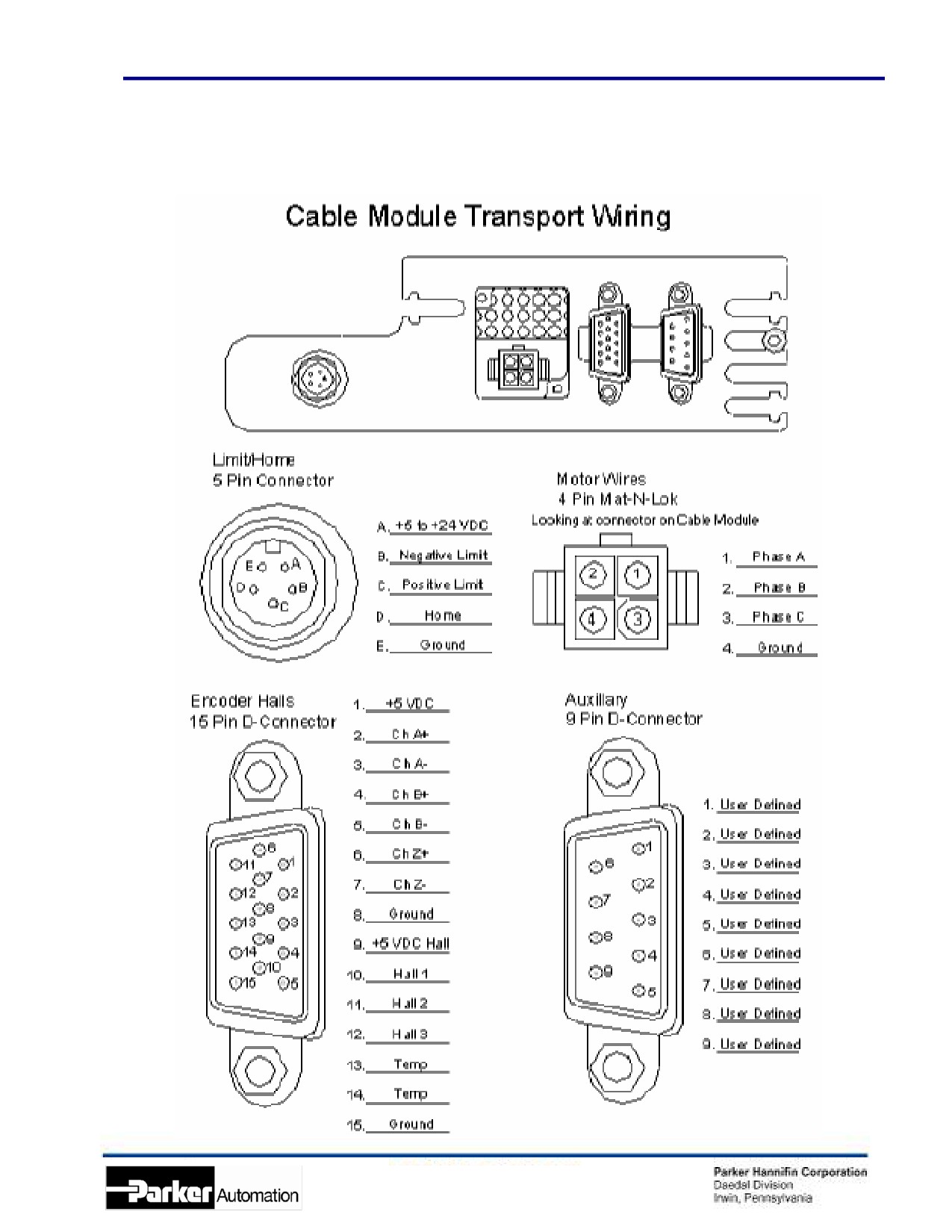
Cabling and Wiring Diagrams
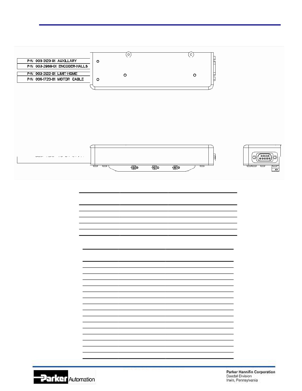
Connector Pin Out and Extension Cable Wire Color Codes
21
404LXR Series Product Manual
Chapter 2 - 404LXR Series Table Specifications
OEM Cable Option
Motor Connections
Function
Cable Wire
404LXR Connector Female**
Color
Phase A
Black #1
1
Phase B
Black #2
2
Phase C
Black #3
3
Ground
Green/Yellow
4
Shield
Shield
Shield Case
Encoder Connections
Function
Cable Wire
404LXR High Density
Color
15 Pin “D” Connector**
+ 5VDC
Red
1
Ch A+
White
2
Ch A-
Yellow
3
Ch B+
Green
4
Ch B-
Blue
5
Ch Z+
Orange
6
Ch Z-
Brown
7
Ground
Black
8
+5 VDC (Hall)
White/Blue
9
Hall 1
White/Brown
10
Hall 2
White/Orange
11
Hall 3
White/Violet
12
Temp
Yellow/Orange
13
Temp
Yellow/Orange
14
Ground
White/Green
15
Shield
Green/Yellow Stripe
Shield Cover
22
404LXR Series Product Manual
Chapter 2 - 404LXR Series Table Specifications
Limit and Home Connections
Function
Cable Wire
404LXR Connector Male
Color
5 Pin Connector**
+ 5 to +24 VDC
Red
A
Negative Limit
Blue
B
Positive Limit
Orange
C
Home
Green
D
Ground
Black
E
Shield
Shield
Shield Case
Auxiliary Connections
Function
Cable Wire
404LXR Connector Female
Color
9 Pin “D” Connector**
User Defined
Red
1
User Defined
Blue
2
User Defined
White
3
User Defined
Yellow
4
User Defined
Orange
5
User Defined
Green
6
User Defined
Purple
7
User Defined
Brown
8
User Defined
Black
9
User Defined
Shield
Shield Cover
** Available only on Cable Transport Module Option. The OEM Option terminates in flying leads.
23
404LXR Series Product Manual
Chapter 3 - How to Use the 404LXR
Chapter 3 - How to Use the 404LXR
Mounting Surface Requirements
Proper mounting of the 404LXR is essential to optimize product performance. All
specifications are based on the following conditions:
•
The positioner must be bolted down along its entire length.
•
The positioner must be mounted to a flat, stable surface, with a flatness error less than or equal to
0.013mm/300mm.
• Catalog specifications may deviate for positioners mounted to surfaces that do not meet the
above conditions.
• If the surface does not met these specifications the surface can be shimmed to comply with
these requirements.
•
If mounting conditions require that the table base is overhung, table specifications will not be met over
that portion of the table. Additionally, in X-Y Systems the overhung portion of the Y-axis may not met
specifications due to the additional error caused by deflection and non-support of the base. Contact
Daedal for guidelines on specifications of overhang applications.
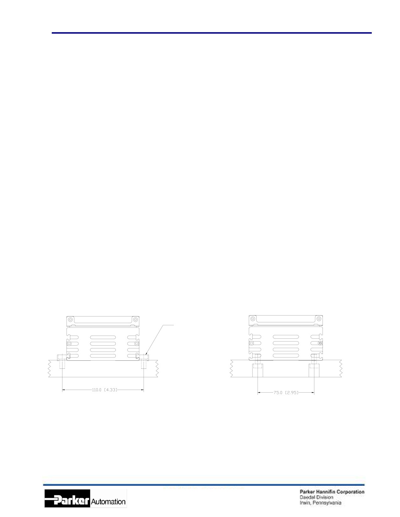
Mounting Methods
The 404LXR can be mounted via the two (2) following methods:
1) Toe Clamps
2) Taped Holes on the underside of the 404LXR
Toe Clamp
Toe Clamp Mounting
Bottom Tapped Holes
P/N 100-8376-01
M5 X 0.8 X 7.5 Long
Counterbores for M6
Note: Maximum Allowable
Bolt Length is 7.0 mm
24
404LXR Series Product Manual
Chapter 3 - How to Use the 404LXR
Side and Inverted Mounting Concerns
Side Mounting
• Cable transport modules are NOT to be used on side mounted positioners with travels
greater than 600 mm due to cable drag.
Inverted Mounting
• Cable transport modules are NOT to be used on inverted mounted positioners with travels
greater than 450 mm due to cable drag. Contact factory for special bracketry.
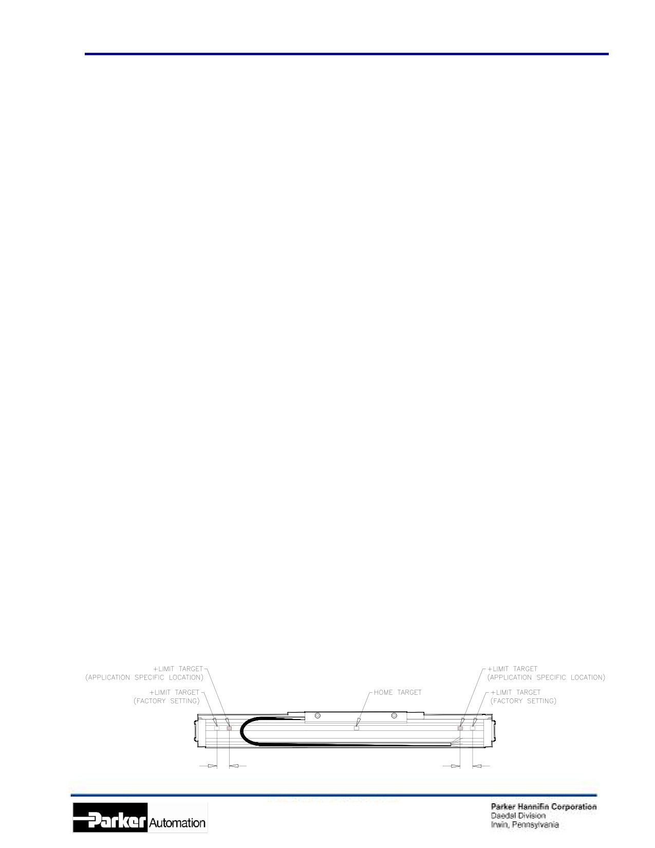
Setting Travel Limit Sensors
The LXR is supplied with over-travel limit sensors. Set the position of the sensors before applying
power. The limit sensors are set at the factory for maximum travel. These factory settings only
allow for 3mm (0.12”) before the carriage contacts the deceleration bumper. In slow speed
applications this may be adequate, however as the top speed of the application increases the
required deceleration distance increases. To determine the safe Deceleration Distance the
Maximum Speed and the Maximum Obtainable Deceleration Rate must be known or calculated.
The maximum speed should be known from your application requirements. Velocity limits should
be set in your program or in your amplifier to cause a fault if the speed exceeds this value. The
maximum deceleration is a factor of load and available peak force of the table. Using F = ma,
calculate maximum acceleration and then required deceleration distance. See the following
example for calculating maximum deceleration for an application with a payload = 5kg on a
404LXR-D13 (8 pole motor), with a maximum speed of 1.5 m/s.
Payload mass = 5 kg, Carriage mass = 1.5 kg
Total mass = 6.5 kg
Maximum Speed = 1.5 m/sec
Available peak force at 1.5 m/sec = 155N (See Chapter 2, Force / Speed Curve)
Thus: F = ma a = F/m a = 155N / 6.5kg
23.8 m/sec2 or 2.4g’s
The Maximum Obtainable Deceleration Rate for this application is 23.8 m/sec2.
Now, calculate the Deceleration Distance for linear deceleration:
First… find the Deceleration time:
Ta = Max Velocity / Deceleration Rate
Ta = 1.5m/sec / 23.8 m/sec2
0.063 seconds
Second… find the Deceleration Distance:
Distance = ((Max Velocity) * (Ta)) / 2
Distance = ((1.5 m/sec) * (0.063)) / 2
0.047 meters or 47 mm
This means that both the positive and negative limit switch targets must be moved inward by 47mm.
The limit deceleration rate should be set to 24.22 meters/sec2.
47 mm
47 mm
25
404LXR Series Product Manual
Chapter 3 - How to Use the 404LXR
Setting Home Sensor
The 404LXR is equipped with a “home” position reference sensor. This is located on the same
bracket as the limit sensors and the target is located between the limit targets. This sensor is
typically used in conjunction with the encoder “Z” marker (refer to “Z” channel reference below). If
the unit is equipped with this option it will be set at the “Z” channel location. If another home
location is desired the home target can be adjusted by loosening the screws on the target and
sliding it along the track. Note: If the home sensor is used without “Z” channel, repeatability is
reduced to +/-5 microns.
Z Channel Position Reference
The Z channel is an output on the encoder. Many servo controllers support this input. The Z
channel on the 404LXR is located in one of three positions, (positive end, mid travel, or negative
end). The location depends on how the unit was ordered (See Chapter 2, Order Number
Nomenclature). The Z channel is a unidirectional device. This means that the final homing direction
must occur in one direction. The 404LXR is set that the final home direction is to be toward the
positive side of the table (See Chapter 2, Dimensional Drawing, for positive direction definition).
The repeatability of the Z channel is equal to +/- 2 resolution counts of the encoder (except for 0.1
micron scales which have a repeatability of +/-1 microns). Thus the repeatability of the “Z” channel
equals:
Encoder Resolution Z Channel Repeatability
5 micron
+/- 10 micron
1 micron
+/- 2 micron
0.5 micron
+/- 1 micron
0.1 micron
+/- 1 micron
NOTE: Home repeatability is also very dependent on controller input speed and homing algorithms.
The above repeatability does not include possible controller tolerance. Additionally, to achieve the
highest repeatability the final homing speed must be slow. Slower final speed usually results in
higher repeatability.
NOTE: The “Z” channel output is only one resolution count wide. Thus the on-time may be very
brief. Due to this some controllers may have difficulty reading the signal. If you are experiencing
the positioner not finding the “Z” channel during homing, try reducing final homing speed; also refer
to your controller manual for frequency rates of the “Z” channel input.
Grounding / Shielding
All cables are shielded. These shields are to be grounded to a good earth ground. Failure to
ground shields properly may cause electrical noise problems. These noise problems may result in
positioning errors and possible run away conditions.
26
404LXR Series Product Manual
Chapter 3 - How to Use the 404LXR
Cabling
The 404LXR is available with two (2) types of cabling:
• Cable Transport Module
• This is a complete cable management system including high flex ribbon cable (life rating of
20 million cycles), cable carriers, and connector system. This has been engineered for high
life, maintenance free operation. Extension cables are used to connect the table connector
block to the amplifier and controller. Refer to cabling diagrams for pin-out and wire color
information.
• The Cable transport module is replaceable. See Chapter 6, Cable Management Module
Replacement, for replacement P/N’s and a detailed procedure of the replacement process.
• Un-harnessed OEM Cable System
• This option provides high flex round cables directly from the carriage. This option is provided
for applications where the design of the machine already has a cable management system.
Four cables come from the carriage connector: motor, encoder, Hall effect and limit/home
sensor cables.
• Recommended bend radius for these cables is 100mm. This radius will provide 10 million
cycles of the cable. Smaller bend radius will reduce cable life while larger bend radius will
increase life. The un-harnessed OEM cable system can be replaced. Refer to Chapter 6,
Cable Management Module Replacement. The same carriage connector is used here and
can be removed and replaced with a new assembly.
27
404LXR Series Product Manual
Chapter 4 - Performance
Chapter 4 - Performance
Acceleration Limits
Acceleration of the 404LXR is limited by four (4) factors:
•
Linear Bearings
The Linear bearings used in the 404LXR have a continuous acceleration limit of 2 g’s. This means
that the bearings are design to take repetitive acceleration of 2 g's and maintain the rated bearing
life. Additionally, the bearings can take a periodic acceleration of up to 5 g’s, however continued
accelerations of these magnitudes will reduce bearing life.
•
Reduced Bearing Life
Bearing loading due to high acceleration may reduce bearing life to an unacceptable application
limit. This is not usually a limiting factor unless loading is significantly cantilevered causing high
moment loads during accelerations. (Chapter 2, 404LXR Series Technical Data to determine
bearing load life for your application)
•
Available Motor Force
This is the primary factor that reduces acceleration. This is simply the amount of motor force
available to produce acceleration. The larger the inertial and or frictional load the lower the
accelerations limit.
•
Settling Time
In many applications reducing cycle time is a primary concern. To this end, the “settling” time (the
amount of time needed after a move is completed for table and load oscillating to come within
acceptable limits) become very important. In many cases where very small incrementing moves are
executed, the settling time is greater than the actual move time. In these cases accelerations may
need to be reduced thus reducing the settling time.
28
404LXR Series Product Manual
Chapter 4 - Performance
Speed Limits
The Maximum Speed of the 404LXR is limited by three (3) factors:
•
Linear Bearings
The linear bearings are limited to a maximum speed of 3 meters/second.
•
Linear Encoder Limit
The linear encoder has speed limits relative to encoder resolution; these limits are listed below:
Encoder
Maximum Velocity
Required Post
Resolution
Quadrature Input
Bandwidth (²)
5 micron
5 meters/second (¹)
2 Mhz
1 micron
3 meters/second
6.7 Mhz
0.5 micron
1.5 meters/second
6.7 Mhz
0.1 micron
0.3 meters/second
10 Mhz
(¹) When using an encoder with 5 micron resolution, the maximum speed is limited by the square rail bearings.
(²) This is the bandwidth frequency that the amplifier or servo control input should have to operate properly with the
encoder output at maximum speeds. This frequency is post-quadrature, to determine pre-quadrature divide above values by
4. Above frequencies include a safety factor for encoder tolerances and line loses.
•
Force / Speed Limit
The available force of the 404LXR reduces as speed increases. (Chapter 2, 404LXR Series
Technical Data)
Encoder Accuracy and Slope Correction
Encoder Accuracy
The 404LXR Series makes use of an optical linear tape encoder for positional feedback. This
device consists of a readhead, which is connected to the carriage, and a steel tape scale, which is
mounted inside the base of the 404LXR.
The linearity of this scale is +/-3 microns per meter, however the absolute accuracy can be many
times larger. To compensate for this error, an error plot of each 404LXR is done at the factory
using a laser interferometer. From this plot a linear slope correction factor is calculated (see
below). Then a second error plot is run using the slope correction factor. These tests are
conducted with the Point of Measurement (P.O.M.) in the center of the carriage 38 mm above the
carriage surface.
Slope Correction
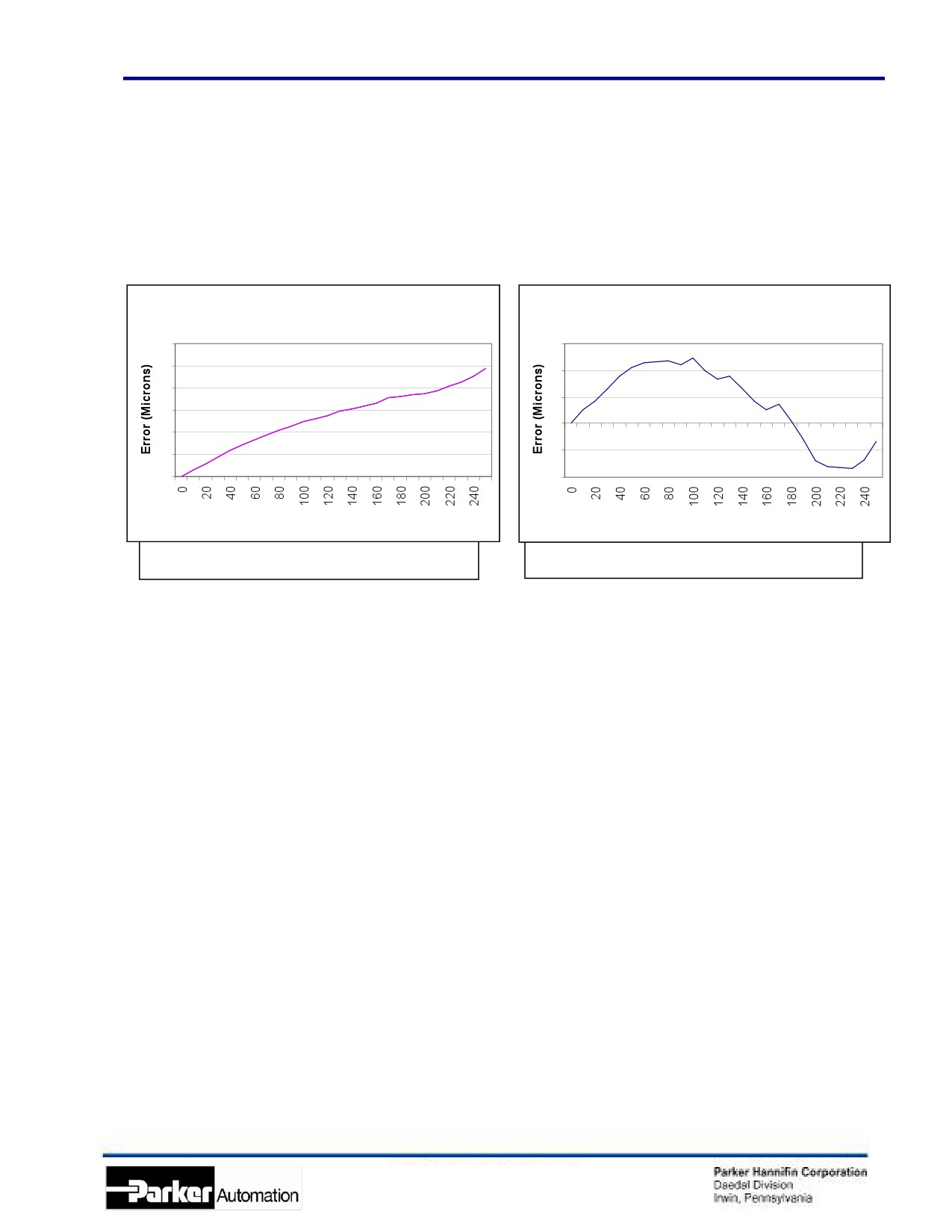
Slope correction is simply removing the linear error of the table. The graphs below show an
example of a non-slope corrected error plot and the same plot with slope correction. As can be
seen, the absolute accuracy has been greatly improved.
The slope factor is marked on each unit. It is the slope of the line in microns per meter. This factor
may be positive or negative, depending on the direction of the error.
29
404LXR Series Product Manual
Chapter 4 - Performance
If your application requires absolute accuracy, the slope factor must be incorporated into the
motion program. This is a matter of either assigning variables for motion positions and using the
slope correction in the variable equation, or if your controller has floating decimal scaling (with high
enough precision) the slope correction can be accounted for in scaling.
NOTE: The zero position (or starting point) of the error plots are at the extreme NEGATIVE end of
travel (refer to Chapter 2, Dimensional Drawing, for Negative end location).
Non-Slope Corrected Error Plot
Slope Corrected Error Plot
60
6
50
4
40
2
30
0
20
-2
10
0
-4
Positions (mm)
Positions (mm)
Non-Slope Corrected Error Plot, Total error 48 microns
Slope Corrected Error Plot, Total error 8.5 microns
Note: Slope Factor is 200 micron / meter in this
Below is a sample program showing how to correct for slope error using variables. This example
program will work with the 6K as well as the 6000 Series Parker, Compumotor Controllers.
Step 2 through 3 of this program should be made a subroutine. This subroutine can then be
executed for each distance.
………………………………………………………………………………………………………..
• Step #1
VAR1 = 880; IN THIS CASE THE DESIRED DISTANCE IS 880mm.
• Step #2
DEL SLCORR ; DELETE SLCORR PROGRAM
DEF SLCORR ; DEFINE SLCORR PROGRAM
VAR2 = (VAR1/1000)* (0.085); VAR2 EQUALS DESIRED DISTANCE (IN METERS) TIMES THE
SLOPE FACTOR (mm/meter)
• Step #3
VAR3 = (VAR1-VAR2); SUBTRACT SLOPE ERROR FROM DESIRED DISTANCE
• Step #4
D(VAR3); SET DISTANCE AS VAR3
END ; END SUBROUTINE
………………………………………………………………………………………………………..
In the example above, the required move distance is 880 mm. But the LXR has a slope error of
0.085mm per meter. This is a positive slope error meaning that if uncorrected the LXR will move
0.085 mm too far for every meter it travels. To correct we must command a smaller position.
• Step #1: The required move distance is set as variable #1.
• Step #2: In this step, we first convert 880 mm to 0.88 meters my dividing by 1000. Next we
multiply by the slope factor to calculate the slope error distance of this move (0.88 * 0.085) =
0.0748 mm.
30
404LXR Series Product Manual
Chapter 4 - Performance
• Step #3: We subtract the error from the original distance (880 - 0.0748) = 879.9252 mm.
• Step #4: Here we simply assign the new calculated distance as our current command
distance.
This same program works if the slope error is negative. For example, if the slope error was -0.085
instead of +0.085 the equation would work out like this:
VAR2 = (880/1000)*(-0.085) = -0.0748
VAR3 = 880 - (-0.0748) = 880.0748
Thus correcting for the negative slope.
Note: Above are examples for incremental moves. The same program works if programming in
absolute coordinates.
Note: Each unit is shipped with both the non-slope corrected accuracy plot and a slope corrected
plot. These plots can be used to “MAP” the table, making positioning even more accurate. Mapping
is correcting for the error of the device at each location. This can be done by knowing the motion
positions and the error at each of these positions and setting up a matrix of variables in your motion
program. This method provides excellent accuracy but is time consuming to setup.
Attainable Accuracy with Slope Correction
Travel
Accuracy
Travel
Accuracy
(mm)
(microns)
(mm)
(microns)
50
6
400
18
100
7
500
21
150
8
600
25
200
10
700
28
250
12
800
31
300
14
900
33
350
16
1000
35
Thermal Effects on Accuracy
All specifications for the 404LXR are taken at 20° C. Variation from this temperature will cause
additional positional errors. If the base of the 404LXR varies from this temperature the encoder
scale will expand or contract, thus changing its measuring length and thus encoder resolution.
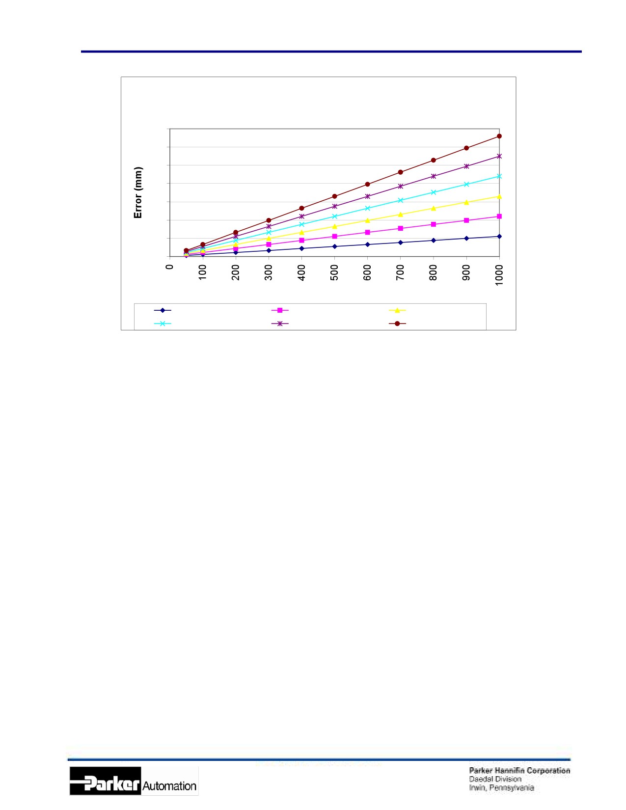
The factor by which this thermal effect occurs is 0.000022mm/mm/° C. Although this sounds like a
very small number it can make significant accuracy and repeatability effects on your applications,
especially on longer travel applications. To understand this better let’s look at an example:
Example: A 404LXR with 900mm travel is being used. The accuracy over the entire travel is 40
microns @ 20° C. If the base temperature increases by 5° C an additional error of 99 microns will
be added over the total travel (0.000022mm/mm/° C)*900mm*5° C. As you can see this error is
significant. However, this additional error can be compensated for since the error is linear.
On the next page is a graph of the accuracy of the 404LXR with respect to base temperature and
travel. Each line represents the additional error of the table caused by the elevated temperature.
31
404LXR Series Product Manual
Chapter 4 - Performance
Temperature Effect on Accuracy
0.7
0.6
0.5
0.4
0.3
0.2
0.1
0
Travel (mm)
5 degrees C
10 degrees C
15 degrees C
20 degrees C
25 degrees C
30 degrees C
Thermal Effects on Repeatability
Repeatability will not be effected as long as the temperature remains constant. However the
repeatability will be effected as the temperature changes from one level to another. This is most
commonly experienced when starting an application cold. Then as the application runs the 404LXR
comes to its operational temperature. The positions defined when the unit was “cold” will now be
offset by the thermal expansion of the unit. To compensate for this offset, all positions should be
defined after the system has been exercised and brought to operational temperature.
Causes of Temperature Increases
One or more of the following conditions may effect the temperature of the 404LXR
base:
•
Ambient Temperature
This is the air temperature that surrounds the 404LXR.
•
Application or Environment Sources
These are mounting surfaces or other items which produce a thermal change that effect the
temperature of the 404LXR base (i.e. Machine base with motors or other heat generating devices
that heat the mounting surface and thus thermally effect the 404LXR base).
•
Motor heating from 404LXR
Since the 404LXR uses a servo motor as its drive, it produces no heat unless there is motion, or a
force being generated. In low duty cycle applications heat generation is low, however as duty
cycles increase, temperature of the 404LXR will increase, causing thermal expansion of the base.
With very high duty cycles these temperatures can reach temperatures as high as 30° C above
ambient.
32
404LXR Series Product Manual
Chapter 4 - Performance
Compensating for Thermal Effects
How much you will have to compensate for the above thermal effects depend on the application
requirements for accuracy. If your accuracy requirements are high, you either need to control base
temperature or program a thermal compensation factor into your motion program. Controlling the
base temperature is the best method. However, this means controlling the ambient temperature by
removing all heat/cold generators from the area and operating at very low duty cycles.
Compensation is the other way of achieving accuracy without sacrificing performance. In this case
the system must be exercised through its normal operating cycle. The temperature of the base
should be measured and recorded from the beginning (cold) until the base becomes thermally
stable. This base temperature should be used in a compensation equation. Below is the
fundamental thermal compensation equation:
Cd = (Id - ( (Id) * (Te) * T))
Cd = Corrected displacement (mm)
Id
= Incremental displacement (mm)
Te = Thermal Expansion (0.000022 mm/mm/° C)
T = Temperature Differential from 20° C
Example:
• Base Temperature of 32° C
• Required move 100mm
Cd = 100mm - (100mm * Te * 12° C) = 99.9736mm
In this move the commanded move should be 26.4 microns less (100mm - 99.9736mm) than the
desired move. This will compensate for the thermal expansion of the scale.
This is a simple linear correction factor and can be programmed in to most servo controllers using
variables for the position commands.
33
404LXR Series Product Manual
Chapter 5 - Connecting the Gemini Amplifier
Chapter 5 - Connecting the Gemini Amplifier
34
404LXR Series Product Manual
Chapter 5 - Connecting the Gemini Amplifier
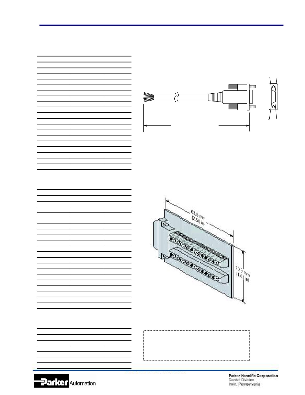
Gemini Adapter Cable
• Use this cable to connect the Encoder and Hall Effect signals from an electrical panel strip to the
Gemini’s 26 pin Motor Feedback connector.
Function
Wire Color
Pin #
Encoder Wires
Ch A+
White
5
Ch A-
Yellow
6
PIN 13
PIN 26
Ch B+
Green
7
Daedal P/N 006-1683-01
Ch B-
Blue
8
Ch Z+
Orange
9
Ch Z-
Brown
10
Ground
Black
3,4
+5 VDC
Red
1,2
Hall Signal Wires
PIN 1
PIN 14
Hall Gnd
White/Green
15
Hall +5V
White/Blue
14
Cable Length = 3 m
Hall 1
White/Brown
16
Hall 2
White/Orange
17
Hall 3
White/Violet
18
Temperature Switch
Temp Switch Yellow/Orange
12
Temp Switch
Yellow/Red
13
Shield
Yellow/Green Shield Cover
Gemini Plug-in Connection Module
• Use this module to directly connect the 404LXR’s Encoder and Hall Effect cables to the Gemini Drive.
Function
Wire Color
Pin #
Encoder Wires
Ch A+
White
5
Ch A-
Yellow
6
Ch B+
Green
7
Ch B-
Blue
8
Ch Z+
Orange
9
Ch Z-
Brown
10
Ground
Black
3,4
+5 VDC
Red
1,2
Shield
Green/Yellow Shield Cover
Hall Signal Wires
Hall Gnd
White/Green
15
Hall +5V
White/Blue
14
Hall 1
White/Brown
16
Hall 2
White/Orange
17
Hall 3
White/Violet
18
Shield
Green/Yellow Shield Cover
Temperature Switch
Temp Switch
Yellow
12
Temp Switch
Yellow
13
Gemini Motor Phase Connections
• Use these Connections to connect the LXR’s Fork Terminal Motor Phase Cable to the Gemini Drive.
Function
Wire Color
Pin #
Note: For Maximum Noise Immunity It is
Motor Phase
recommended that the end of the Motor Cable be strip
Phase A
Black #1
U
back and connected to the Ground clamp located on
Phase B
Black #2
V
the side of the Gemini. See Gemini Hardware manual
Phase C
Black #3
W
for grounding details.
Ground
Green/Yellow
Grd
Shield
Shield
Shield Cover
35
404LXR Series Product Manual
Chapter 5 - Connecting the Gemini Amplifier
External
+24 VDC
Supply
VM25
Module
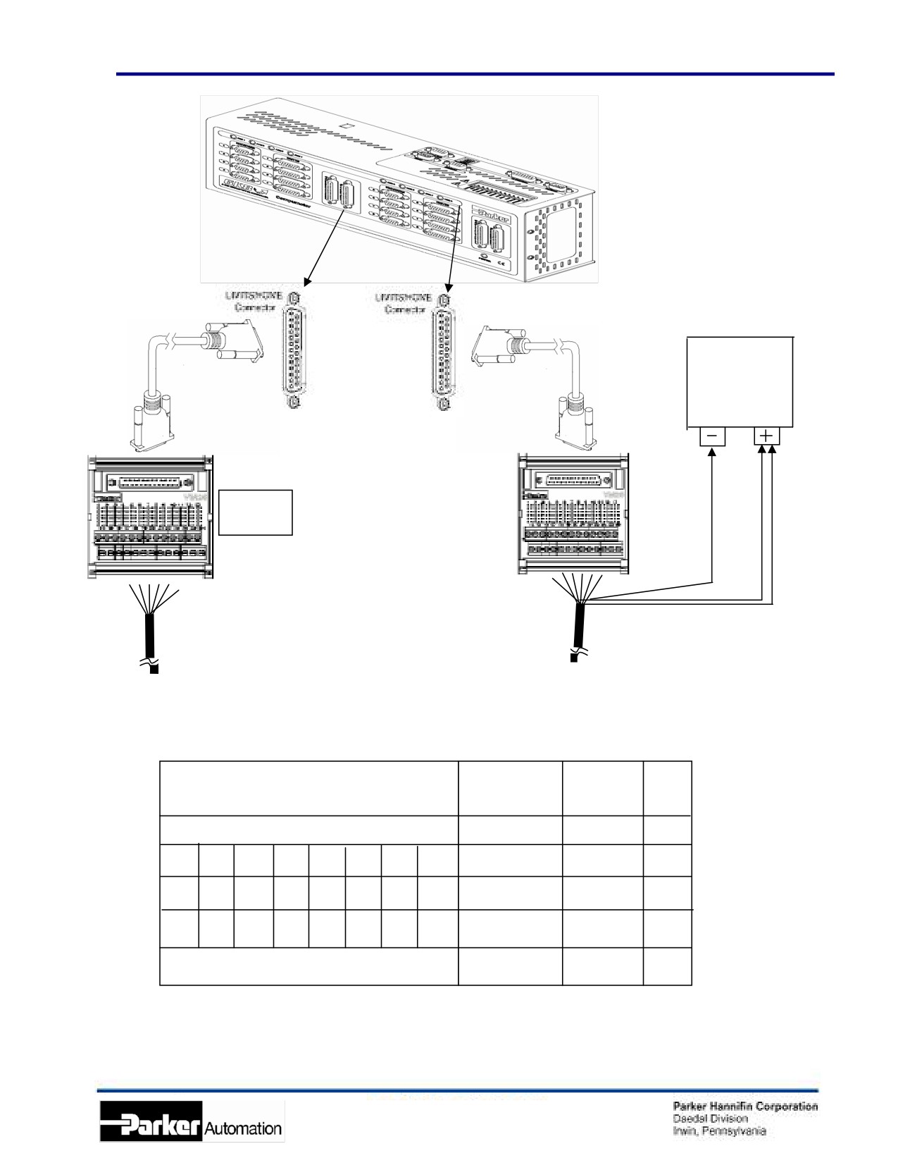
+5 to +24VDC Limit/Home (Red)
LXR Limit/Home Cable
P/N 006-1742-0X
VM25 Pin Outs**
Function
Wire Color*
LXR
6K Axis Number
Pin #
1
2
3
4
5
6
7
8
+5 to +24VDC
Red
A
Connect to external power supply (see above)
21
15
9
3
21
15
9
3
(-) Limit
Blue
B
23
17
11
5
23
17
11
5
(+) Limit
Orange
C
Home
Green
D
19
13
7
1
19
13
7
1
All even pins are connected to logic ground.
Ground
Black
E
* Color scheme of the flying leads from the Limit/Home Cable. P/N 006-1742-0X.
** Axes 1-4 use the first 25-pin limits/home connector and axes 5-8 use the second limits/home connector on the 6K.
36
404LXR Series Product Manual
Chapter 6 - Maintenance and Lubrication
Chapter 6 - Maintenance and Lubrication
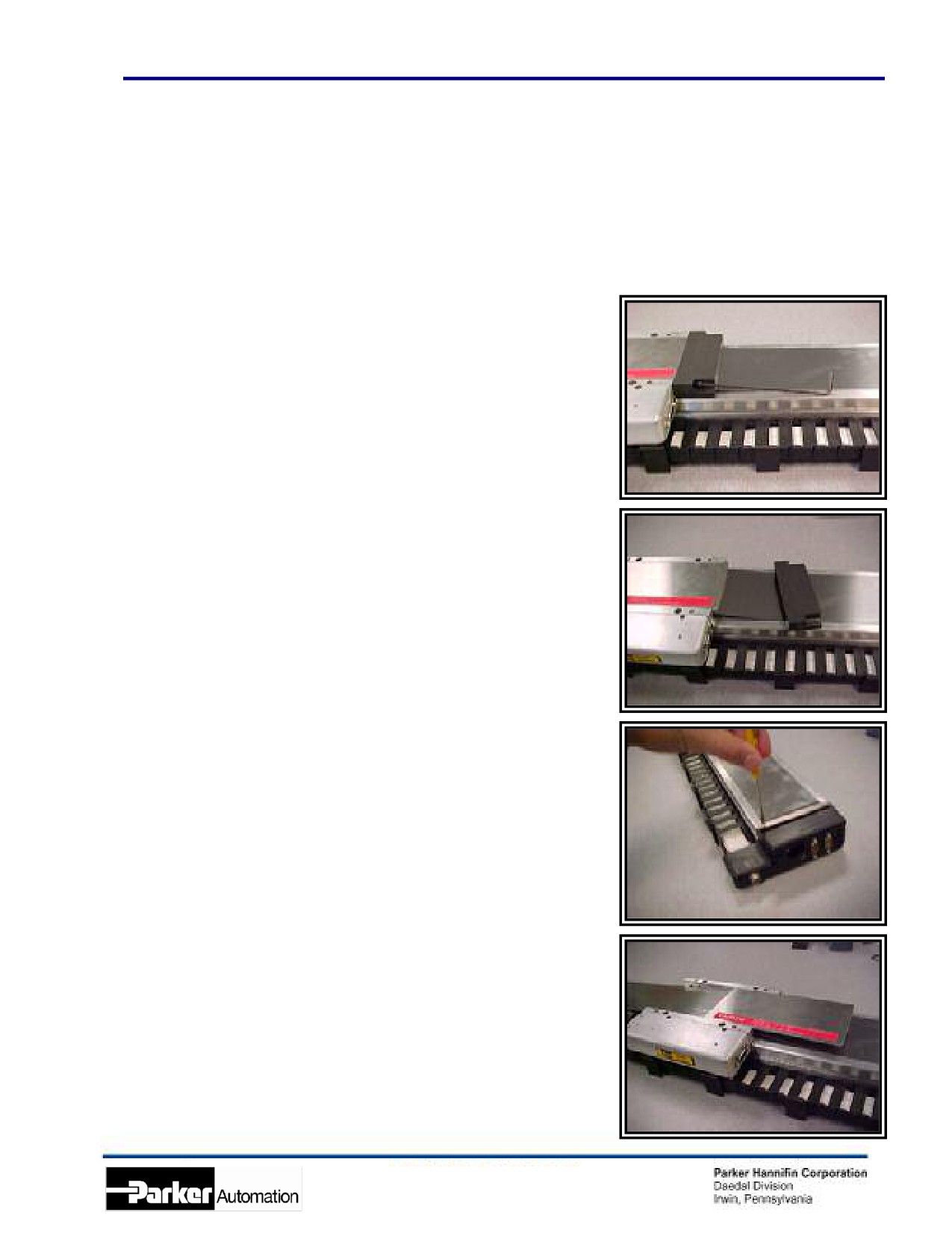
Internal Access Procedure
The following procedure outlines the steps required to access the interior of the positioner.
• Remove carriage end caps by removing four (4) M3 Socket
Head Cap Screws (2pc/carriage side) using a 2.5 mm Allen
wrench.
• Pull carriage end caps off. Carriage end caps on both sides
of carriage must be removed.
• Remove the two (2) strip seals clamps by removing four (4)
Phillips Head Screws.
• Remove strip seal cover plate.
37
404LXR Series Product Manual
Chapter 6 - Maintenance and Lubrication
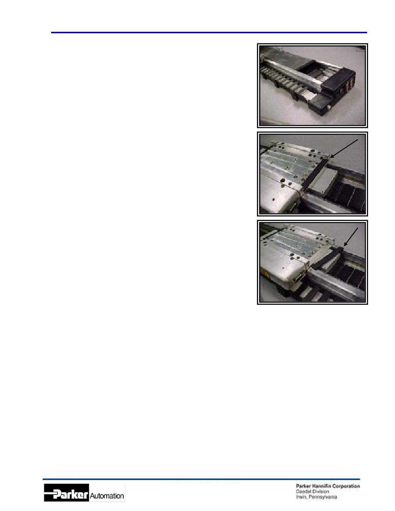
• Carefully pull the strip seal through the carriage.
• Caution: The strip seal ends are VERY SHARP.
• Remove both wear bars that are located on the carriage.
Reassemble positioner by reversing steps.
38
404LXR Series Product Manual
Chapter 6 - Maintenance and Lubrication
Square Rail Bearing Lubrication
See Section on Internal Access for procedure to access interior of positioner.
Materials Required: Daedal Grease type #1, Isopropyl Alcohol, Clean Cloth,
Small Brush
•
Lubrication Type:
Daedal grease type #1, model number G1. Lithium 12 hydoxstearate soap base containing
additives to enhance oxidation resistance and rust protection (viscosity, 70/80 CST at 100 degrees
C) is recommended for grease lubrication.
•
Lubricant Appearance:
Blue and very tacky.
•
Maintenance Frequency:
Square rail bearing blocks are lubricated at our facility prior to shipment. For lubrication inspection
and supply intervals following shipment, apply grease every 1000 hours of usage. The time period
may change depending on frequency of use and environment. Inspect for contamination, chips,
etc, and replenish according to inspection results.
•
Lubricant Application:
Wipe the rails down the entire length with a clean cloth. Apply lubrication on the rails allowing a film
of fresh grease to pass under the wipers and into the recirculating bearings. After bearings are
relubricated clean encoder tape scale located on inside wall of table. Clean with lint free cloth,
removing all dirt and grease. Using a lint free cloth, wipe down linear tape scale with isopropyl
alcohol.
•
Note: Do not use/mix petroleum base grease with synthetic base grease at any time. For lubrication
under special conditions consult factory.
Cable Management Module Replacement
•
Order replacement Cable Management Module Below:
Travel Code Replacement
Travel Code Replacement Travel Code Replacement
Part Number
Part Number
Part Number
T00
006-1730-01
T05
006-1730-03
T13
006-1730-07
T01
006-1730-01
T06
006-1730-04
T15
006-1730-08
T02
006-1730-02
T07
006-1730-04
T17
006-1730-09
T03
006-1730-02
T09
006-1730-05
T19
006-1730-10
T04
006-1730-03
T11
006-1730-06
39
404LXR Series Product Manual
Chapter 6 - Maintenance and Lubrication
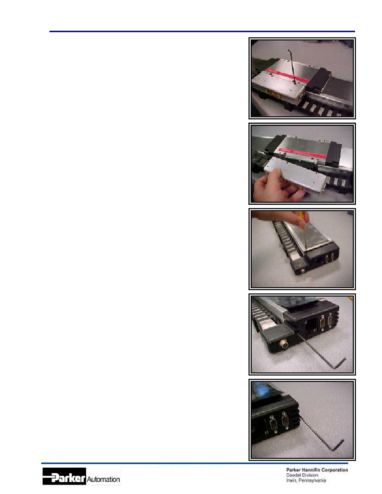
• Remove two (2) M3 Flat Heat Screws from the top of the
cable carrier by using a 2.5 mm Allen wrench.
• Pull the carriage connector off, taking care to pull straight off
to avoid bending the connectors.
• Remove the strip seal clamp on the connector end by
removing two (2) Phillips Head Screws.
• Remove two (2) M3 Button Head Screws from connector
end by using a 2.5 mm Allen wrench.
Replacement modules are mounted by reversing steps.
40
404LXR Series Product Manual
Chapter 6 - Maintenance and Lubrication
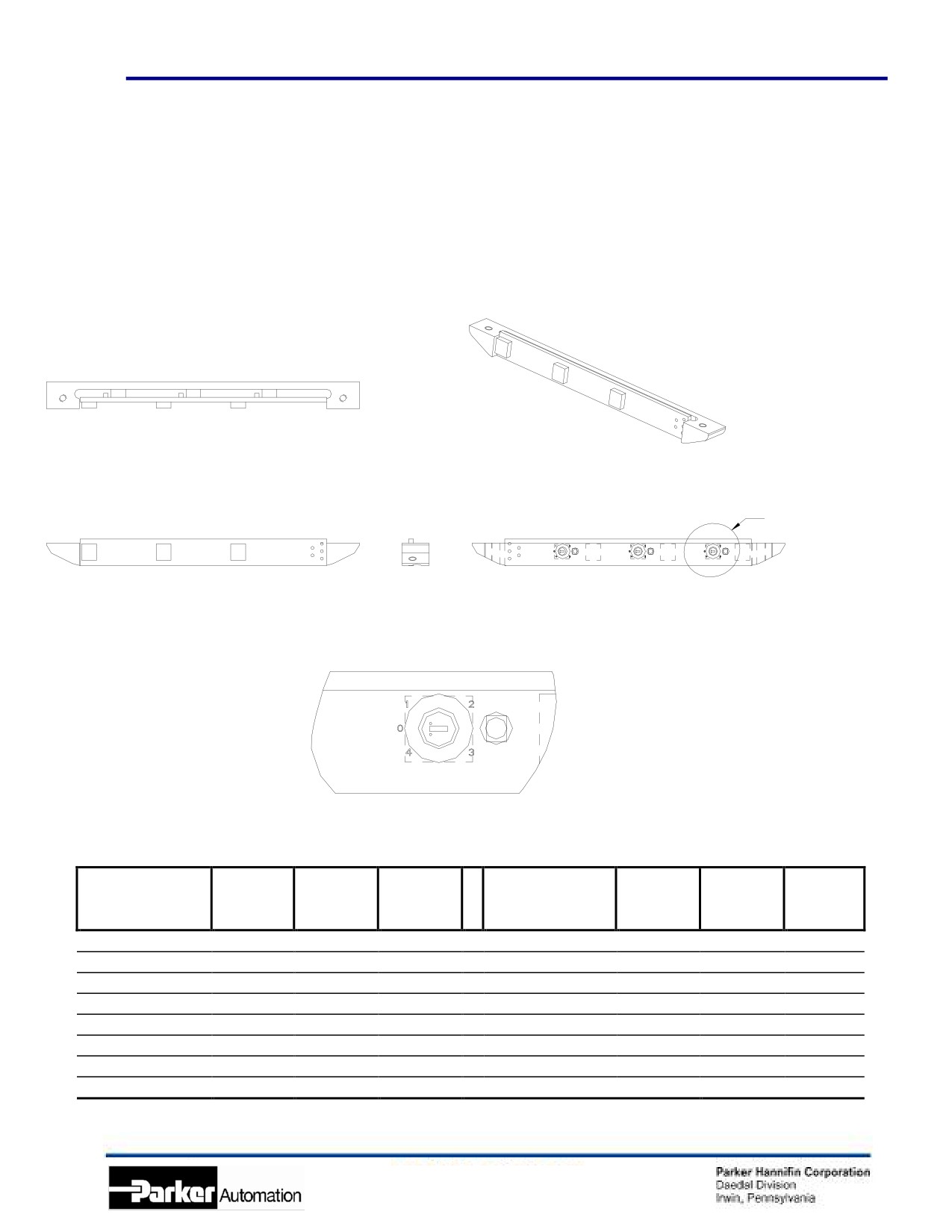
Limit and Home Sensor Module Adjustment
Materials Required: Small flathead screwdriver.
• See switch location table below.
• See following section on Limit and Home Sensor Module Replacement for access to the switch
adjustment.
Switch #1
Switch #3
See Detail Z
Switch #2
Shown in 'Zero' Position
Detail Z
Limit and
Switch
Switch
Switch
Limit and
Switch
Switch
Switch
Home Option
#1
#2
#3
Home Option
#1
#2
#3
Position
Position
Position
Position
Position
Position
H2L2-404LXR
1
1
1
H4L2-404LXR
1
2
1
H2L3-404LXR
3
1
3
H4L3-404LXR
3
2
3
H2L4-404LXR
2
1
2
H4L4-404LXR
2
2
2
H2L5-404LXR
4
1
4
H4L5-404LXR
4
2
4
H3L2-404LXR
1
3
1
H5L2-404LXR
1
4
1
H3L3-404LXR
3
3
3
H5L3-404LXR
3
4
3
H3L4-404LXR
2
3
2
H5L4-404LXR
2
4
2
H3L5-404LXR
4
3
4
H5L5-404LXR
4
4
4
41
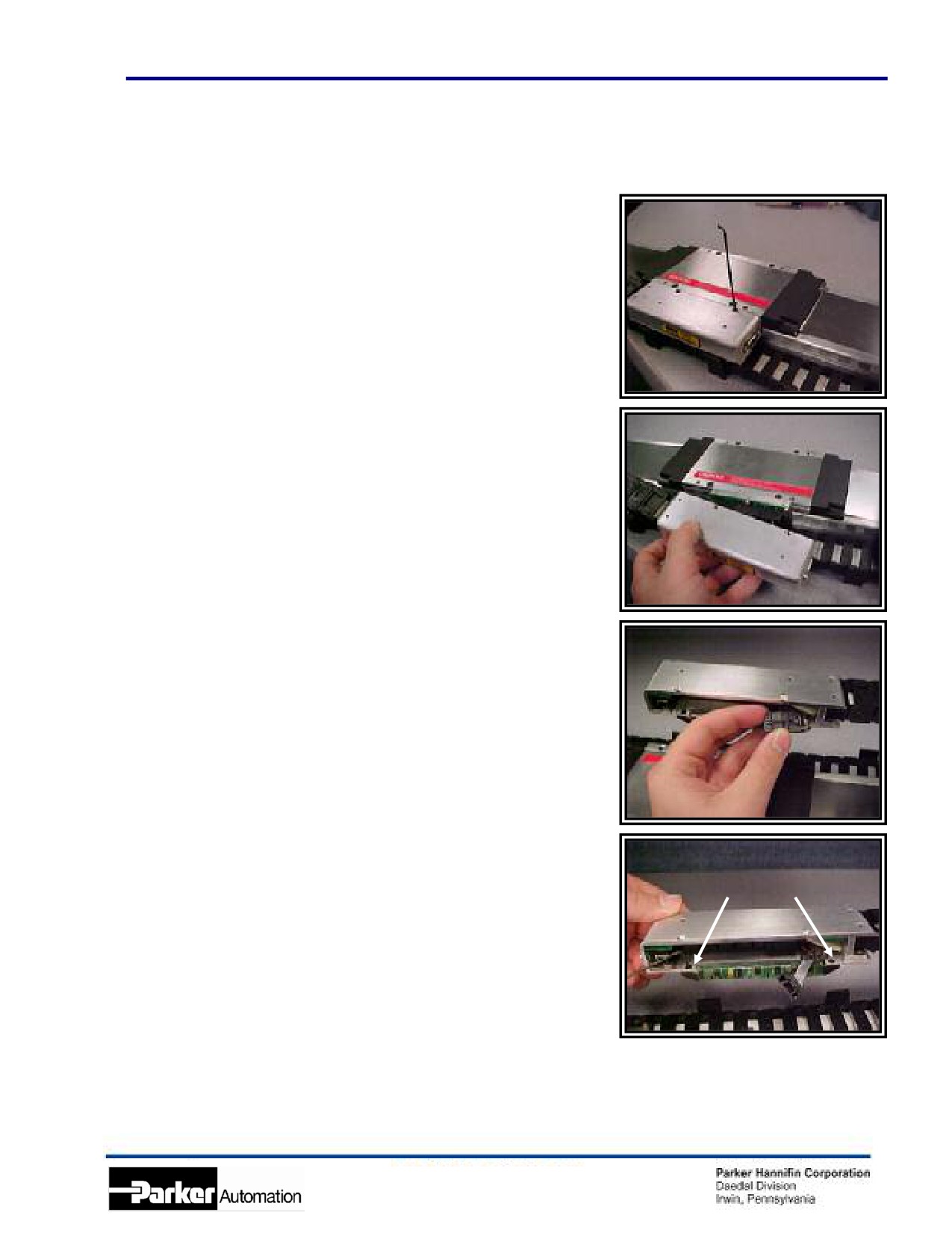
404LXR Series Product Manual
Chapter 6 - Maintenance and Lubrication
Limit and Home Sensor Module Replacement
• Remove two (2) M3 Flat Head Screws from the top of the
cable carrier by using a 2.5 mm Allen wrench.
• Pull the carriage connector off, taking care to pull
straight off to avoid bending the connectors.
• Locate the limit/home wire connection. Press on
the release tab to disengage the connector.
• Remove the two (2) M2 Flat Head Screws that
attach the limit/home switch to the cable carrier
using a 1.5 mm Allen wrench.
Replacement switches are mounted by reversing steps.
42
404LXR Series Product Manual
Appendix A - Understanding Linear Motors
Appendix A - Understanding Linear Motors
The Linear Motor Concept
Linear Motors are basically a conventional rotary servo motor unwrapped. So now what
was the stator is now called a forcer and the rotor becomes a magnet rail. With this
design, the load is connected directly to the motor. No more need for a rotary to linear
transmission device.
Linear Motor Benefits
•
High speeds: Only the bus voltage and the speed of the control electronics limit the maximum
speed of a linear motor. Typical speeds for linear motors are 3 meters per second with 1 micron
resolution and over 5 meters per second with courser resolution.
Note: Motors must be sized for specific loading conditions.
•
High Precision: The feedback device controls the accuracy, resolution, and repeatability of a
linear motor driven device. And with the wide range of linear feedback devices available today,
resolution and accuracy are primarily limited to budget and control system bandwidth.
•
Fast Response: The response rate of a linear motor driven device can be over 100 times
faster than some mechanical transmissions. This is simply because there is no mechanical
linkage. This means faster accelerations and settling times, thus more throughput.
•
Stiffness: Because there is no mechanical linkage in a linear motor, increasing the stiffness is
simply a matter of gain and current. Thus the spring rate of a linear motor driven system can be
many times that of a ball screw driven device. However it must be noted that this is limited by
the motor’s peak force, the current available, and the resolution of the feedback.
•
Zero Backlash: Since there are no mechanical components there is no backlash. There are
however, resolution considerations which effect the repeatability of the positioner (See Chapter
2, General Table Specifications, Chapter 3, Setting Home Sensor and Z Channel Position
Reference)
•
Maintenance Free Drive Train: Because linear motors of today have no contacting parts, in
contrast with screw and belt driven positioners, there is no wear on the drive mechanism.
Slotless Linear Motor Design
The Linear Motor inside the 404LXR is a Slotless Linear Motor. The following will give a
brief description of the motor design and construction:
•
Construction: Designed by the Compumotor and Daedal Divisions of Parker Hannifin, the
motor takes its operating principle from Parker’s slotless rotary motors which have grown
popular over the past few years. The magnetic rail is simply a flat iron plate with magnets
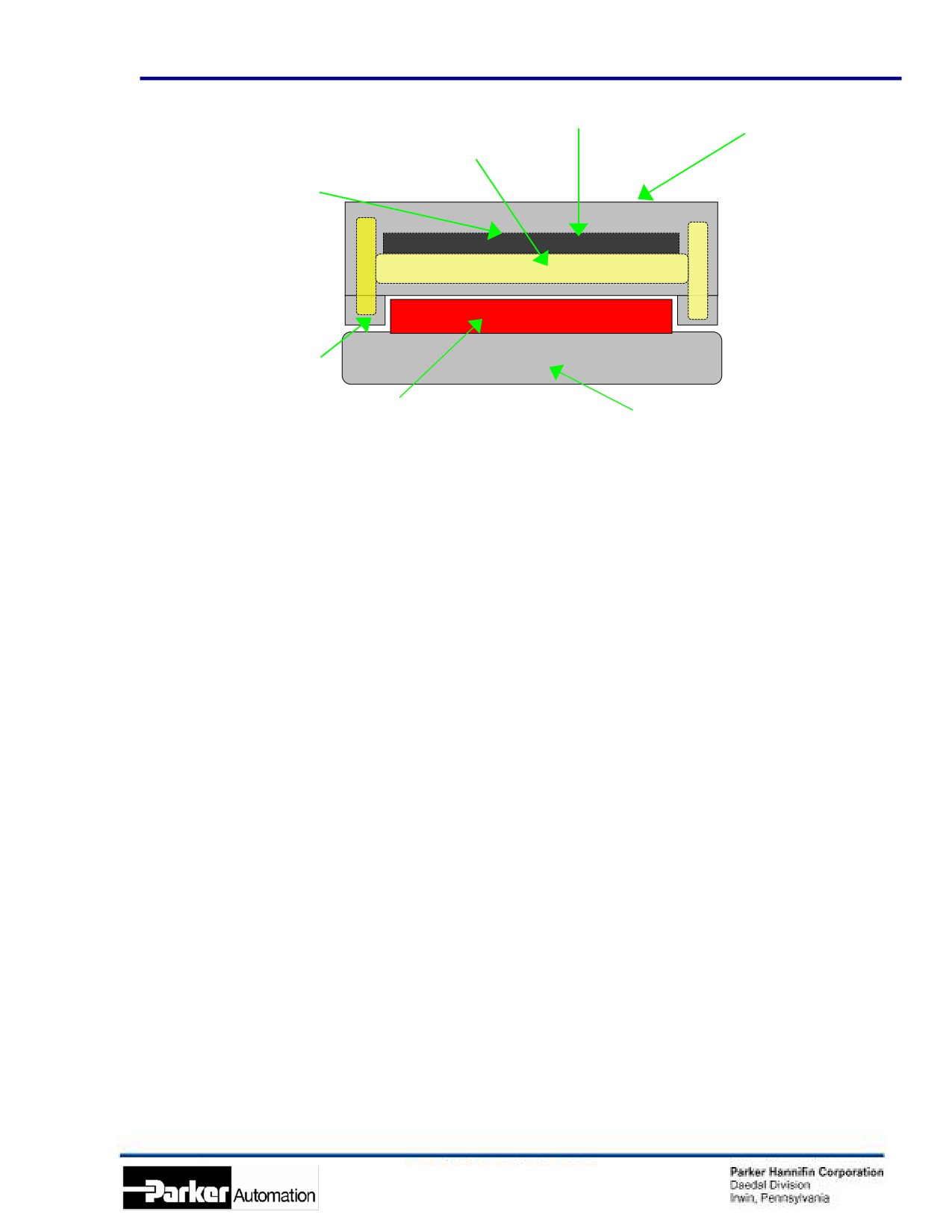
bonded to it. The forcer is unique. It begins with a coil and a “backiron” plate, which is placed
behind the coil. This assembly is placed inside an aluminum housing with an open bottom. The
housing is then filled with epoxy, securing the winding and “backiron” into the housing. The
thermal sensors and hall effect sensors are mounted to the housing.
43
404LXR Series Product Manual
Appendix A - Understanding Linear Motors
Backiron
Aluminum Cap /
Coil Assembly
Mounting Plate
(Houses Backiron and
Thermal Sensors built
Coil Assembly)
into Coil Assembly
Hall Effect Sensors
mounted to Housing
Rare Earth Magnets
Iron Plate
“Single Row”
Advantages/Disadvantages of Slotless
Linear Motors
•
Lower Weight Magnetic Rail: Since this is a single magnet rail the weight is less then half of
dual magnet rail motors. This means less load and higher throughput in multi-axis systems.
•
Structurally Strong Forcer: With the body of the forcer being made of aluminum and the
windings being bonded to this housing, the strength of the forcer is much greater than that of
the epoxy only housed motors. Thus reducing the possibility of motor fatigue failures.
•
Light Weight Forcer: Because of its aluminum body construction, the slotless linear motor
forcer weight is approximately 2/3 that of an equivalent iron core linear motor. Thus resulting in
higher throughput in light load applications.
•
Lower Attractive Forces: The slotless design has a “backiron” causing attractive forces
between the forcer and the rail. However, this attractive force is significantly less than other
linear motors. Thus significantly reducing loading on the linear guide bearings and increasing
bearing life.
•
Lower Cogging: Due to the larger magnetic gap between the magnets and forcer “backiron”
the slotless design has lower cogging. This enables the slotless design to operate in
applications that require very good velocity control.
•
Heat Dissipation: The slotless design, with the coil resting across the “backiron”, which is in
direct contact with the aluminum housing, has very good heat transfer characteristics and is
easy to manage.
44
404LXR Series Product Manual
Appendix B - Internal Protection
Appendix B - Internal Protection
The 404LXR is protected from its environment via a magnetically retained protective
seal. Daedal has conducted testing to determine the degree to which the positioner is
protected by using a British standard called an Ingress Protection Rating (IP Rating).
Definition
Reference: British standard EN 60529 : 1992
This standard describes a system of classifying degrees of protection provided by
enclosures of electrical equipment. Standardized test methods and the establishment of
a two digit numeric rating verify the extent of protection provided against access to
hazardous parts, against ingress of solid foreign objects, and against the ingress of
water.
First Number - The first number indicates protection of persons against access to
dangerous parts and protection of internal equipment against the ingress of solid
foreign objects.
1 - Protection against access to hazardous parts with the back of a hand, and
protected against solid foreign objects of 50 mm diameter and larger.
2 - Protection of fingers against access to dangerous parts, and protection of
equipment against solid foreign objects of 12.5 mm diameter and larger.
3 - Protection against access to hazardous parts with a tool, and protection
against solid foreign objects of 2.5 mm diameter and larger.
Second Number - The second number indicates protection of internal equipment
against harmful ingress of water.
0 - No special protection provided.
Note: Number Indicators above represent only a partial list of IP Rating specifications.
Warnings (Points of Clarity)
•
The specification applies to protection of particles, tools, parts of the body, etc., against
access to hazardous parts inside the enclosure. This does not cover external features such
as switch pinch points, pinch points causes by the motion of the carriage, or cable carrier
assemblies.
•
The testing method as specified in the standard uses a solid steel rod of the appropriate
diameter at a specified force. The specification does not consider soft or pliable particles.
Due to the design of the table and sealing method, a soft particle can compress due to the
motion of the table, and reduce its cross-section. This can allow particles to enter the unit.
•
In application, shavings or chips commonly created in a machining operation are a greater
concern. If any edge or dimension of the “chip” is under the appropriate diameter, it can
wedge under and start to the lift the seals. This action will allow larger particles to do the
same until failure is reached.
45
404LXR Series Product Manual
Appendix B - Internal Protection
Product Rating
All standard configurations will pass IP20 specifications with the following
exception:
• The cable carrier is not covered by the specification.
All standard configurations, (less cable carrier), can be configured to pass IP30
specifications by utilizing the “IP ship kit” supplied with each unit as follows:
• Using the supplied aluminum foil disks, cover all counter-bored base mounting holes that are
not covered by your mounting surface. The disks should be installed from the outside of the
unit. Depending on the travel length, some disks will not be used.
• Using the supplied aluminum foil disks, plug all unused carriage mounting holes that are not
covered by the load or load plate.
• Using the supplied aluminum foil disks, plug all threaded base mounting holes that are not
covered by your mounting surface. Depending on the travel length, some disks will not be
used.
46