Parker 506/507/508 Product Manual (2011)
506/507/508
Product Manual
HA389427 Issue 12
FAILURE OR IMPROPER SELECTION OR IMPROPER USE OF THE PRODUCTS
DESCRIBED HEREIN OR RELATED ITEMS CAN CAUSE DEATH, PERSONAL
INJURY AND PROPERTY DAMAGE.
This document and other information from Parker-Hannifin
Corporation, its subsidiaries and authorized distributors
provide product or system options for further investigation by
users having technical expertise.
The user, through its own analysis and testing, is solely
responsible for making the final selection of the system and
components and assuring that all performance, endurance,
maintenance, safety and warning requirements of the
application are met. The user must analyze all aspects of the
application, follow applicable industry standards, and follow
the information concerning the product in the current product
catalog and in any other materials provided from Parker or its
subsidiaries or authorized distributors.
To the extent that Parker or its subsidiaries or authorized
distributors provide component or system options based upon
data or specifications provided by the user, the user is
responsible for determining that such data and specifications
are suitable and sufficient for all applications and reasonably
foreseeable uses of the components or systems.
Cont-2
Safety Information
!
Requirements
IMPORTANT:
Please read this information BEFORE installing the equipment.
Intended Users
This manual is to be made available to all persons who are required
to install, configure or service equipment described herein, or any
other associated operation.
The information given is intended to highlight safety issues, EMC
considerations, and to enable the user to obtain maximum benefit
from the equipment.
Complete the following table for future reference detailing how the
unit is to be installed and used.
INSTALLATION DETAILS
Model Number
(see product label)
Where installed
(for your own information)
Unit used as a:
♦ Component
(refer to Certification for the
♦ Relevant Apparatus
Inverter)
♦ Wall-mounted
Unit fitted:
♦ Enclosure
Application Area
The equipment described is intended for industrial motor speed
control utilising AC induction or AC synchronous machines.
Personnel
Installation, operation and maintenance of the equipment should be
carried out by qualified personnel. A qualified person is someone
who is technically competent and familiar with all safety information
and established safety practices; with the installation process,
operation and maintenance of this equipment; and with all the
hazards involved.
Product Warnings
Earth/Ground
Caution
Caution
Protective
Risk of electric
Refer to
Conductor
shock
documentation
Terminal
Cont-3
Safety Information
!
Hazards
DANGER! - Ignoring the following may result in injury
1. This equipment can endanger life by
5. For measurements use only a meter
exposure to rotating machinery and
to IEC 61010 (CAT III or higher).
high voltages.
Always begin using the highest
range.
2. The equipment must be permanently
CAT I and CAT II meters must not
earthed due to the high earth leakage
be used on this product.
current, and the drive motor must be
6. Allow at least 5 minutes for the
connected to an appropriate safety
drive's capacitors to discharge to safe
earth.
voltage levels (<50V). Use the
3. Ensure all incoming supplies are
specified meter capable of measuring
isolated before working on the
up to 1000V dc & ac rms to confirm
equipment. Be aware that there may be
that less than 50V is present between
more than one supply connection to the
all power terminals and earth.
drive.
7. Unless otherwise stated, this product
4. There may still be dangerous voltages
must NOT be dismantled. In the
present at power terminals (motor
event of a fault the drive must be
output, supply input phases, DC bus and
returned. Refer to "Routine
the brake, where fitted) when the motor
Maintenance and Repair".
is at standstill or is stopped.
Safety Information
!
WARNING! - Ignoring the following may result in injury or damage
to equipment
SAFETY
Where there is conflict between EMC and Safety requirements, personnel safety
shall always take precedence.
• Never perform high voltage resistance
• All control and signal terminals are
checks on the wiring without first
SELV, i.e. protected by double
disconnecting the drive from the circuit
insulation. Ensure all external wiring
being tested.
is rated for the highest system
voltage.
• Whilst ensuring ventilation is sufficient,
provide guarding and /or additional
• Thermal sensors contained within the
safety systems to prevent injury or
motor must have at least basic
damage to equipment.
insulation.
Cont-4
• When replacing a drive in an
• All exposed metalwork in the Inverter
application and before returning to use,
is protected by basic insulation and
it is essential that all user defined
bonded to a safety earth.
parameters for the product’s operation
• RCDs are not recommended for use
are correctly installed.
with this product but, where their use
is mandatory, only Type B RCDs
should be used.
EMC
• In a domestic environment this product
• This is a product of the restricted
may cause radio interference in which
sales distribution class according to
case supplementary mitigation
IEC 61800-3. It is designated as
measures may be required.
“professional equipment” as defined
in
• This equipment contains electrostatic
EN61000-3-2. Permission of the
discharge (ESD) sensitive parts.
supply authority shall be obtained
Observe static control precautions when
before connection to the low voltage
handling, installing and servicing this
supply.
product.
Safety Information
!
CAUTION!
APPLICATION RISK
• The specifications, processes and circuitry described herein are for guidance only
and may need to be adapted to the user’s specific application. We can not
guarantee the suitability of the equipment described in this Manual for individual
applications.
RISK ASSESSMENT
Under fault conditions, power loss or unintended operating conditions, the drive may
not operate as intended.
In particular:
• Stored energy might not discharge to
• The motor's direction of rotation might not
safe levels as quickly as suggested, and
be controlled
can still be present even though the
• The motor speed might not be controlled
drive appears to be switched off
• The motor might be energised
A drive is a component within a drive system that may influence its operation or
effects under a fault condition.
Consideration must be given to:
• Stored energy
• Supply disconnects
• Sequencing logic
• Unintended
operation
Cont-5
Contents
Contents
Page
CHAPTER 1 PRODUCT OVERVIEW
1-1
Description
1-1
Product Range
1-1
CHAPTER 2 OVERVIEW OF THE 506/507/508
2-1
CHAPTER 3 TERMINAL DESCRIPTION
3-1
Control Terminals
3-1
Power Terminals
3-2
Auxiliary Terminals
3-2
Switches
3-3
Potentiometers
3-3
LEDS
3-3
CHAPTER 4 INSTALLING THE 506/507/508
4-1
Installation
4-1
Speed Control
4-1
Current Control
4-1
Wire Sizes
4-2
Requirements for UL Compliance
4-3
Motor Overload Protection
4-3
Short Circuit Protection Requirements
4-3
Short Circuit Rating
4-3
Operating Ambient Temperature
4-3
Field Wiring Temperature Rating
4-3
Field Wiring Terminal Markings
4-3
Power Wiring Terminals
4-3
Block Diagram
4-4
Terminal Tightening Torque
4-6
Field Grounding Terminals
4-6
Fitting
4-6
Removing the Cover
4-7
Filter
4-8
EMC Connections
4-9
Installation and Set-Up
4-9
Warning
4-9
Switch Selection
4-9
Potentiometer
4-10
Motor
4-10
Wiring
4-10
Applying Power
4-10
Cont-6
Contents
Contents
Page
Fault Finding
4-12
CHAPTER 5 ROUTINE MAINTENANCE AND REPAIR
5-1
Routine Maintenance
5-1
Repair
5-1
Returning the Unit to Parker SSD Drives
5-1
CHAPTER 6 EMC CERTIFICATION FOR THE 506/507/508
6-1
Certificates
6-1
CHAPTER 7 TECHNICAL SPECIFICATIONS
7-1
Input Supply
7-1
Speed Control
7-1
Current (Torque) Control
7-1
Adjustment Range
7-2
Environmental Requirements
7-2
EMC Technical Ratings
7-3
Electrical Ratings
7-4
Output Ratings with typical armature voltage, Va, 80/90V (160/180V)
7-4
Adjustment Ranges
7-4
Product Code
7-5
Cont-7
1-1 Overview of the 506/507/508
Chapter 1 PRODUCT OVERVIEW
Description
The 506/507/508 series controllers are compact, non-isolated motor
speed controllers specifically designed for dc shunt would and
permanent magnet motors. The controllers are intended to operate
from a single phase AC mains supply in the ranges 110/120V AC or
220/240V AC 50/60Hz.
The controllers are intended to be mounted on a length of DIN rail in
an enclosure.
Control of the associated DC motor is achieved by using a linear
closed loop feedback signal based on the motor's own DC armature
voltage. This enables constant motor speed to be maintained
throughout variable motor loads. Improved speed measurement can
be obtained by using a tacho-generator, connected to the motor's
shaft, to provide the feedback signal.
A current loop within the speed feedback path ensures that safe
current levels are always provided to the armature of the motor up to
the level set by the maximum current potentiometer (Imax). This
adjustment is linear and switchable to a lower range of half the
controller current.
If the controlled motor is stalled (e.g. due to either a faulty field
circuit or an excessive load), then a stall timer will remove current
from the motor after approximately 15 seconds. Severe armature
current overloads, are protected against by an instantaneous over-
current trip.
The controllers may also be used in a linear motor torque mode by
using an adjustable setpoint. In this mode of operation over-speed
limiting is a standard feature.
Product Range
Product Rating
Adjustment Switched
Standard
506
3A DC Full Load Current
0.5 to 3A
0.25 to 1.5A
507
6A DC Full Load Current
1 to 6A
0.5 to 3A
508
12A DC Full Load Current
2 to 12A
1 to 6A
506/507/508 - HA389427
Overview of the 506/507/508
2-1
Chapter 2 OVERVIEW OF THE 506/507/508
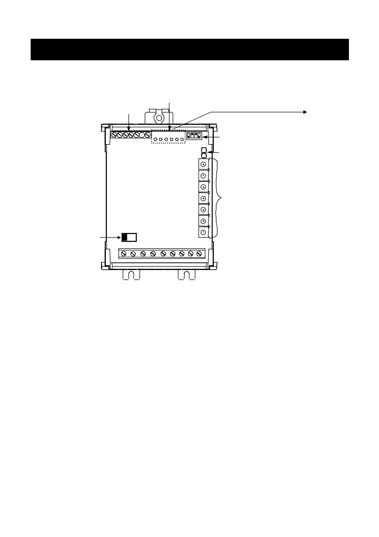
Figure 2.1 Recognition Drawing
Auxiliary Inputs
Control
Note:
Auxiliary
ON
Customer
Terminal is
1 2 3 4 56
1
2
3
4
not fitted on
Personal Switches
standard
Indicators
models but a
special build
can be
ordered with
terminal
Pots
block fitted.
Mains
Switch
110/120V
220/240V
User Supplied Safety Components
Speed /
Torque Potentiometer
10K Isolated spindle and insulating knob
Switch
Rated for input supply voltage.
Note: Safety Components provide Isolation for the User. These
components should be selected to provide a double insulated
(or reinforced) isolation boards for the user suitable for the
input supply voltage used. The product is designed for use in a
pollution degree 2 environment, overvoltage category III,
enclosure mounted. (Refer to EN61010, IEC664 or EN50178
for more information regarding the correct selection of these
components).
Optional Ancillary Components
EMC Filter 18A ac(12A dc) CO389115
506/507/508 - HA389427
3-1 Terminal Description
Chapter 3 TERMINAL DESCRIPTION
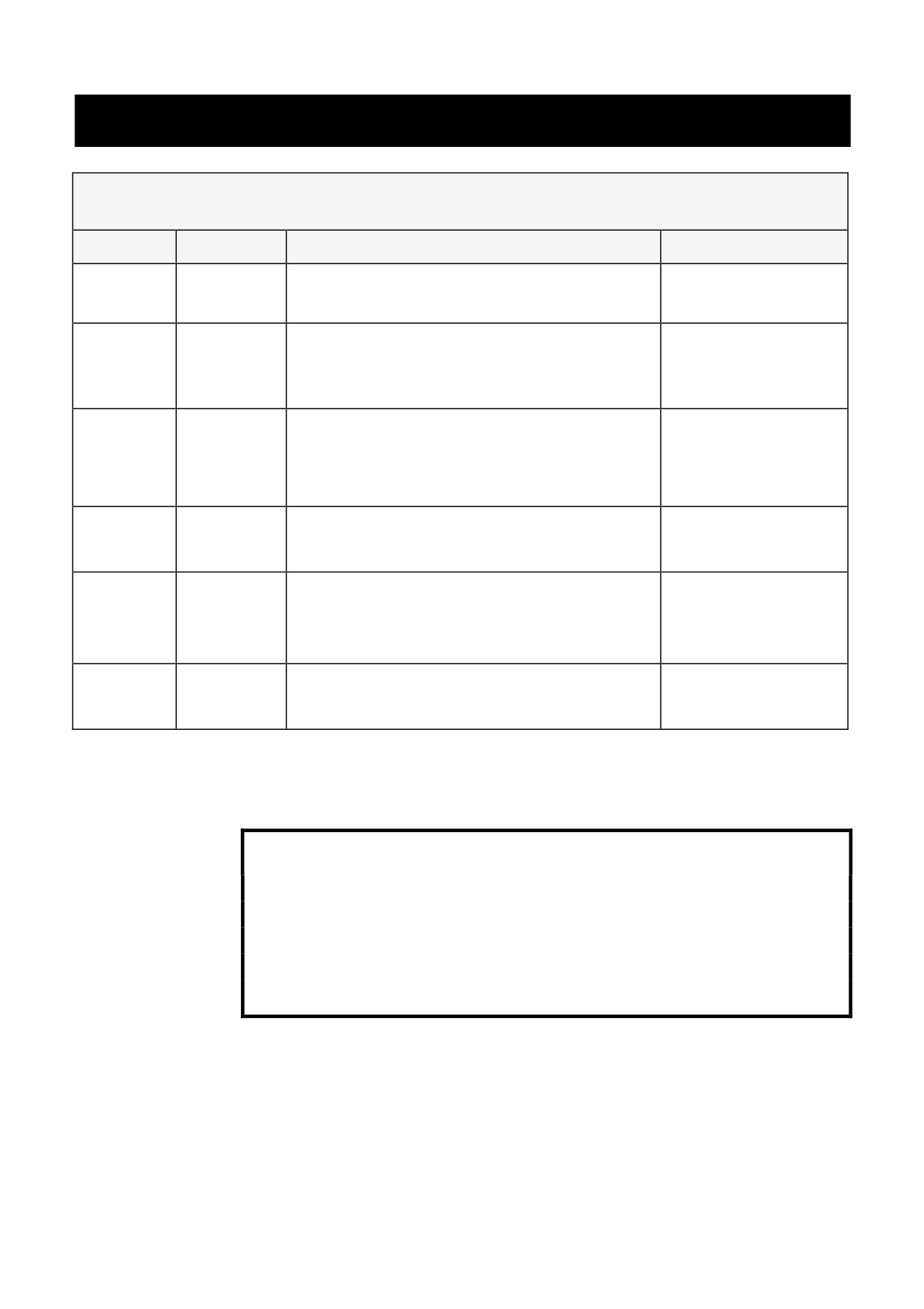
Control Terminals
Terminal
Function
Description
Notes
1
Tacho
Motor Mounted Tachogenerator Input
200V dc Max.
Feedback
Terminal.
2
0V-Signal
Control Signal Reference.
Must NOT be
Common
Earthed
(Grounded).
3
Run
Digital Input to Enable Controller.
Input Impedance
Connect to 0V to Run in Speed.
-> 20k Ohm
Connect to + 10V to Run in Current.
4
Speed
Analogue Input,
Input Impedance
Setpoint
0v to +10V = 0 to 100% Speed.
- 66k Ohm
5
+10V
Analogue Output,
Load - 2mA
Reference
+10V Reference for Speed and
Current Setpoints.
6
Current
Analogue Input,
Input Impedance
Limit
0 to +10V=0 to 100% Current
- 100k 0hm
Note: Auxiliary Terminal is not fitted on standard models but a special build can
be ordered with terminal block fitted.
WARNING!
This is a non-isolated product. The control connections
are not isolated from the AC supply. Any connection to
earth or use of earth (ground) referenced components either
deliberately or unintentionally will cause permanent damage
to the controller.
506/507/508 - HA389427
Terminal Description
3-2
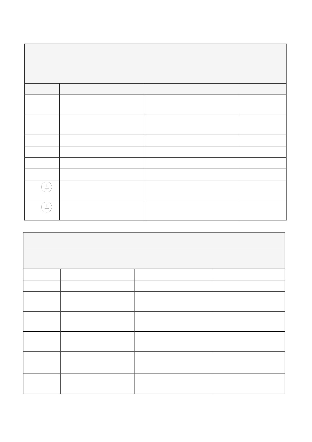
Power Terminals
The product may be connected phase - to - phase provided the resultant
voltage does not exceed the maximum supply voltage specified.
Terminal
Function
Description
Notes
L1 (L)
AC Input Live
AC Supply Terminal Line 1
or Live
L2 (N)
AC Input Neutral
AC Supply Terminal Line 2
or Neutral
F+
Field Positive
Field Output Positive
F-
Field Negative
Field Output Negative
A-
Armature Negative
Armature Output Negative
A+
Armature Positive
Armature Output Positive
Protective Earth (Ground)
Drive Module Protective
Grd
Earth (Ground)
Protective Earth (Ground)
Motor Protective Earth
Grd
(Ground)
Auxiliary Terminals
* The power must be supplied from an independent power supply
which is not earth (ground) referenced.
Terminal
Function
Description
Notes
A1
Auxiliary Supply
Auxiliary Relay Supply
+16V at 10mA
A2
0V - Signal Common
Signal Reference
Must not be earthed
(grounded)
A3
Zero Speed
Zero Speed Output
24V at 50mA open
Collector *
A4
Health
Health Output
24V at 50mA open
Collector *
A5
Zero Speed Level
Zero Speed Output
For other levels see
Table 3.1
Level Trim
A6
Auxiliary Setpoint
Auxiliary Direct Speed
+10V @ 100K Full
Setpoint
Speed Input
506/507/508 - HA389427
3-3 Terminal Description
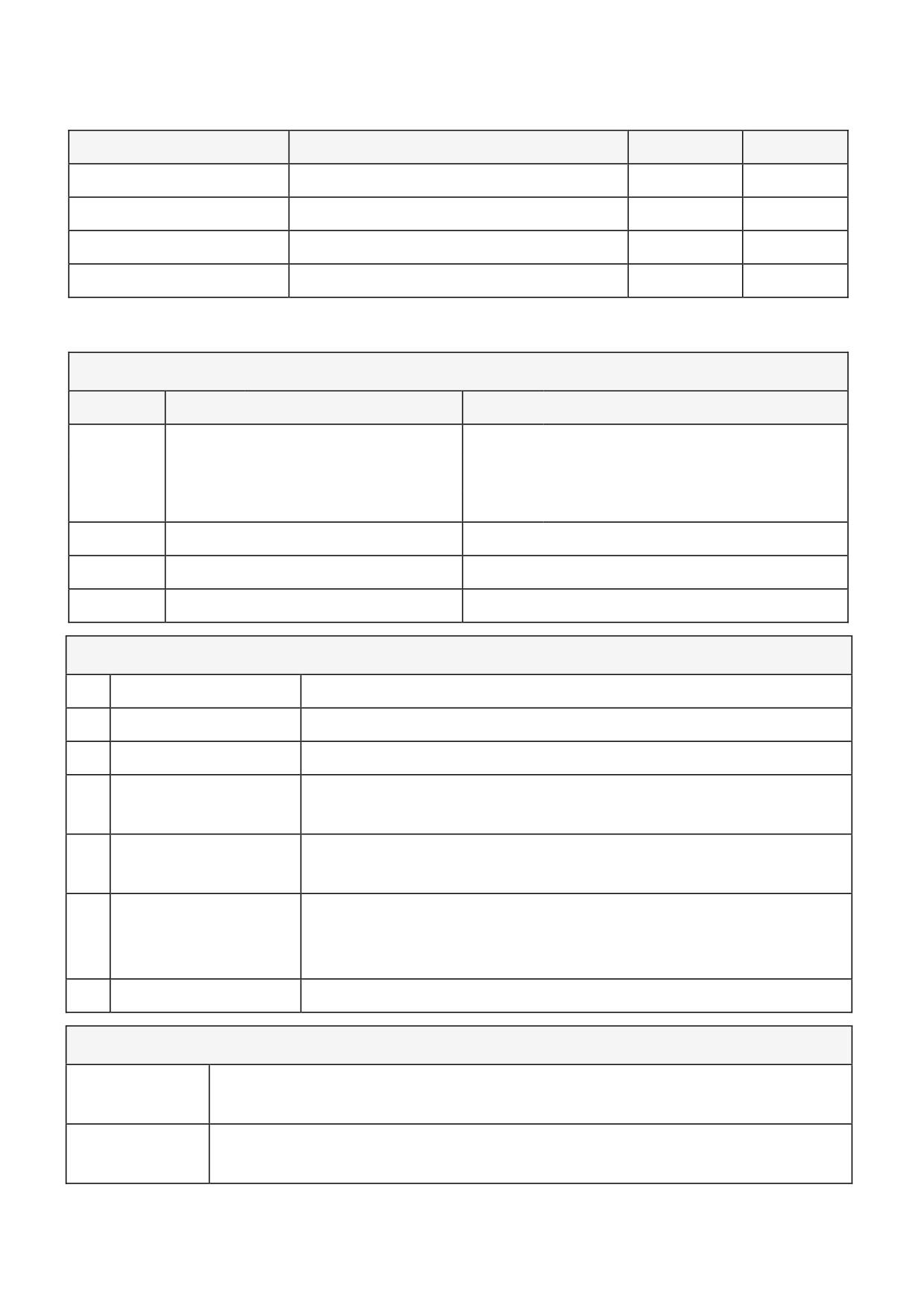
Table 3.1
External Resistor
Terminal Volts at Zero Speed
180Va
90Va
--
10.75V
6%
12%
4k7
5.5V
3%
6%
2k2
2.5V
2%
4%
1k
2V
1%
2%
The zero speed detector operates from the Controller Output voltage, the default level is
set to 6% of 180V dc.
Switches
Switch
Off
On
SW1
Imax.
506 - 0.25 to 1.5A
Imax.
506 - 0.5 to 3.0A
Imax.
507 - 0.5 to 3.0A
Imax.
507 - 1.0 to 6.0A
Imax.
508 - 1.0 to 6.0A
Imax.
508 - 2.0 to 12.0A
SW2
½ Speed Demand
Full Speed Demand
SW3
¼ Speed Feedback
Full Speed Feedback
SW4
Tacho Feedback
Armature Feedback
Potentiometers
P1
RAMP UP
Setpoint ramp adjustment clockwise to increase time.
P2
RAMP DOWN
Setpoint ramp adjustment clockwise to increase time.
P3
SPEED STABILITY
Speed loop stability clockwise increase response.
P4
CURRENT
Output current calibration clockwise to increase output.
CALIBRATION
P5
IR
Speed droop compensation armature voltage feedback.
COMPENSATION
P6
MINIMUM SPEED
Clockwise to increase compensation. Minimum speed at
zero setpoint.
(Can also be used as zero speed trim
anticlockwise to reduce speed at zero setpoint).
P7
MAXIMUM SPEED
Maximum speed calibration clockwise to increase speed.
LEDS
POWER-ON
Indicates power supply is present on terminals.
(Note:- This LED
does not indicate that the CORRECT voltage is applied).
HEALTH
When illuminated the controller is unhealthy due to either an
overcurrent trip or a stall trip condition. Should normally be "OFF".
506/507/508 - HA389427
Installing the 506/507/508
4-1
Chapter 4 INSTALLING THE 506/507/508
Installation
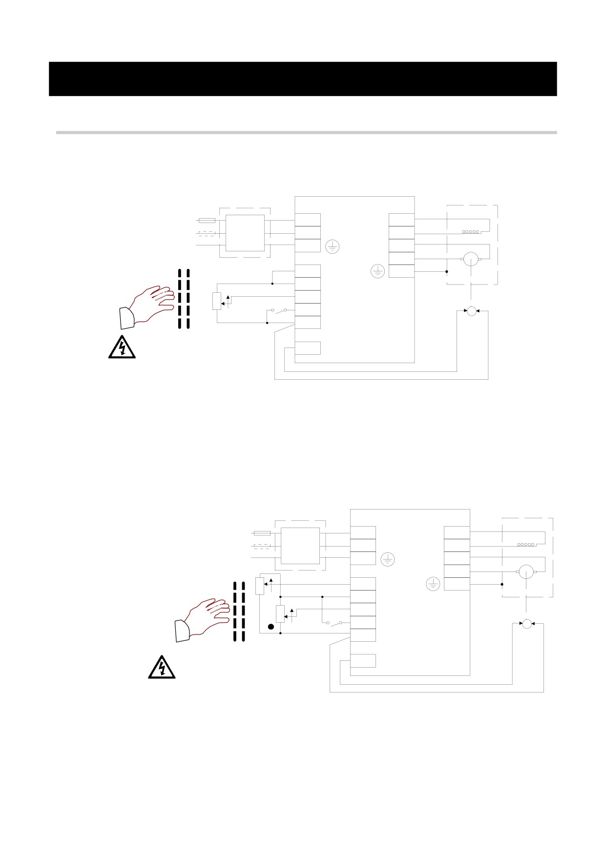
Speed Control
Figure 4.1 Wiring Diagram Speed Control
Fuse
FF
L1
F +
Fuse
MAINS
F
L2/N
F -
FILTER
A
GRD
A -
AA
A +
6
I LIMIT
GRD
5
+ 10 V
4
SETPOINT
10K
RUN
3
RUN
2
COMMON
T6
neutral
Double/reinforced insolation
boundary provided by users
1
TACHO GENERATOR
potentiometer and run switch
* Additional line fuse recommended for applications where live
connections are made rather than live and netral.
'Run' connects to Common to 'Enable' Speed Control.
Current Control
Figure 4.2 Wiring Diagram Current Control
Fuse
FF
L1
F +
Fuse
MAINS
F
L2/N
F -
FILTER
A
GRD
A -
AA
A +
10K
6
I LIMIT
GRD
5
+ 10 V
4
SETPOINT
10K
RUN
3
RUN
2
COMMON
T6
SPEED SETPOINT
neutral
Double/reinforced insolation
1
TACHO GENERATOR
boundary provided by users
potentiometers and run switch
• Optional Speed Setpoint potentiometer to limit overspeed, connect
setpoint direct to +10V if not required.
* Additional line fuse recommended for applications where live
connections are made rather than live and netrual
'Run' connected to +10V to 'Enable' Current Control and
'Override' Stall detection.
506/507/508 - HA389427
4-2 Installing the 506/507/508
WARNING!
Ensure that all wiring is electrically isolated and cannot be
made "live" unintentionally by other personnel.
Wire Sizes
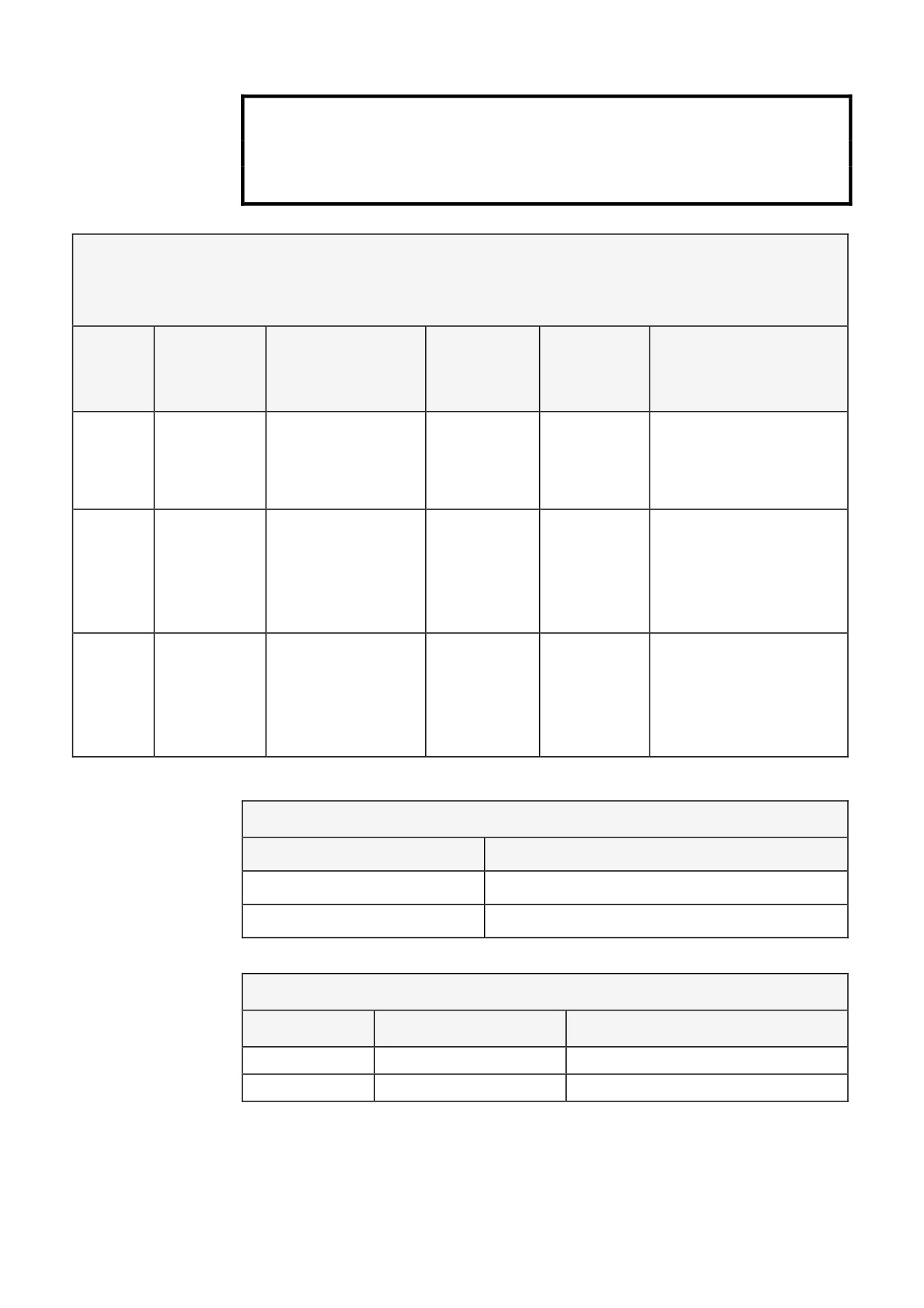
* Contains semiconductor fuses as recommended below.
Model
Maximum
Function
Cable
AC Supply
Parker Fuse Isolator
Output
(Wire) Size
Fuse
Kit Part Numbers *
Rating
Rating
506
3A
DC Armature,
1.5mm2/
10A
LA054664
16AWG
AC Supply,
Ground
507
6A
AC Supply,
2.5mm2/
10A
LA054664
Ground
14AWG
DC Armature
1.5mm2/
16AWG
508
12A
AC Supply
6.0mm2/
20A
LA050062
10AWG
DC Armature,
4.0mm2/
Ground
12AWG
Terminal Tightening Torques
Terminal
Torque Setting
Power
0.8 Nm
7 lbf-in
Control
0.56 Nm
5 lbf-in
Ferraz Semiconductor Fuses
Fuse Rating
Ferraz Type No.
Parker Part No.
10A, 250V
250VFA10A6X32
CH230014
20A, 250V
250VFA20A6X32
CH230024
506/507/508 - HA389427
Installing the 506/507/508
4-3
Requirements for UL Compliance
For installations requiring compliance with UL Standards.
Motor Overload Protection
An external motor overload protective device must be provided by
the installer. This device can comprise of a thermal sensor within
the motor winding monitored by an external relay but this
combination cannot be evaluated by UL. Hence, it is the
responsibility of the installer/local inspector to determine whether
the combination is in compliance with the National Electrical Code
or local code requirements.
Short Circuit Protection Requirements
UL Recognized semiconductor fuses must be installed upstream of
the controllers. Refer to the semiconductor fuses table on the
previous page for recommended semiconductor fuse manufacturer
and type number.
Short Circuit Rating
The 506 and 507 controllers are suitable for use on a circuit capable
of delivering not more than 1000 RMS symmetrical amperes, 240V
maximum; whilst the 508 controller is suitable for use on a circuit
capable of delivering not more than 5000 rms symmetrical amperes,
240V maximum.
Operating Ambient Temperature
The maximum operating ambient temperature rating is 40oC.
Field Wiring Temperature Rating
Use 75oC copper conductors only.
Field Wiring Terminal Markings
For correct field wiring connections that are to be made to each
terminal, refer to Chapter 5: “Terminal Description” - Power
Terminals and Chapter 3 “Technical Specification” - Control
Terminals.
Power Wiring Terminals
The power wirint terminals accept a maximum conductor size of No.
10 AWG (5.3mm2).
506/507/508 - HA389427
4-4 Installing the 506/507/508
Installing the 506/507/508 4-5
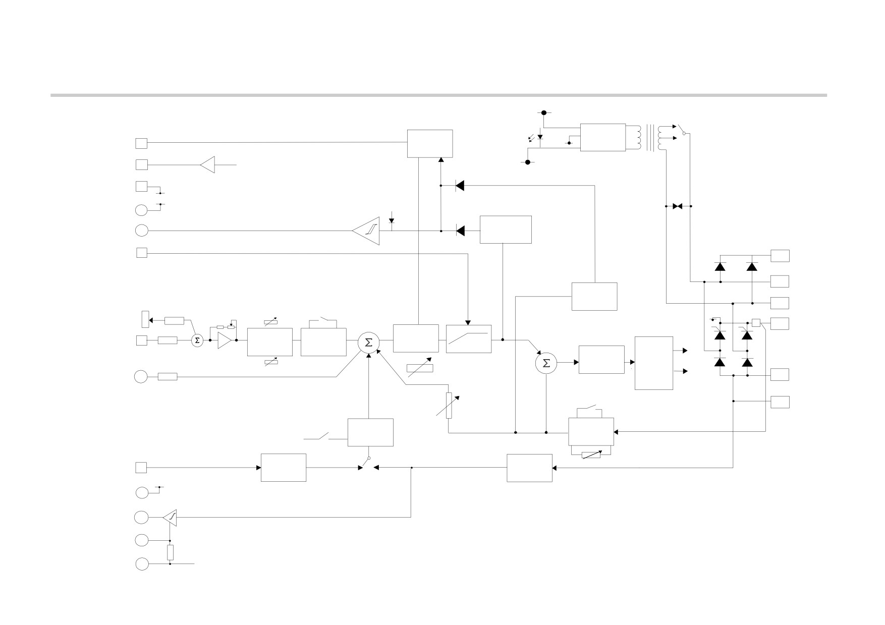
Block Diagram
TRANSFORMER SELECTION SWITCH
+12V
220/240
LED 1
110/120
POWER
0V
POWER
RUN
T3
QUENCH
ON
SUPPLY
-10V REF
+10V REF
T5
-12V
0V COMMON
T2
0V
LED 2
+16V
HEALTH
A1
DRIVE
HEALTH
STALL
A4
HEALTHY
PROTECTION
TORQUE /
TORQUE/CURRENT LIMIT
10V = 100%
T6
SETPOINT
F +
L1
OVER
CURRENT
+20%
TRIP
L2/N
P7
SW2
MIN
UP RATE P1
MAXSPEED
SPEED
0v
A+
P6
-2%
+
SPEED
100%
LINEAR
+
SPEED
SETPOINT
T4
LOOP
CURRENT
SETPOINT I/P
RAMP
SCALE
+
+
PI
CLAMP
+
--
+
CURRENT
FIRING
P3
LOOP
STAB
PI
CIRCUIT
AUXILIARY
DOWN RATE P2
A --
A6
--
SETPOINT
P5
SW1
IR
F --
COMP
SPEED
CALIBRATED
CURRENT
RANGE &
SW3
ARMATURE CURRENT
SCALING
SCALE
TACHO-
ARMATURE
P4
TACHO
TACHO
ARM. VOLTAGE
I limit
ARMATURE VOLTAGE
GENERATOR
T1
VOLTAGE
FILTER
I/P
SW4
FILTER
A1
+16V
ZERO SPEED
A3
INTERLOCK
BLOCK DIAGRAM 506/507/508
ZERO SPEED
A5
LEVEL
A2
0V
506/507/508 - HA389427
4-6 Installing the 506/507/508
Terminal Tightening Torque
Refer to the Terminal Tightening torque table shown on page 4-2 for
both the Power and Control Terminals.
Field Grounding Terminals
The field grounding terminals are identified with the International
Grounding Symbol
(IEC Publication 417, Symbol 5019).
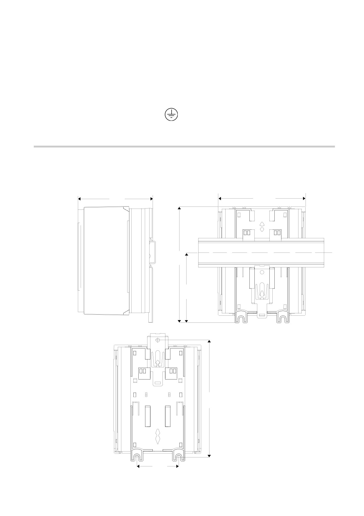
Fitting
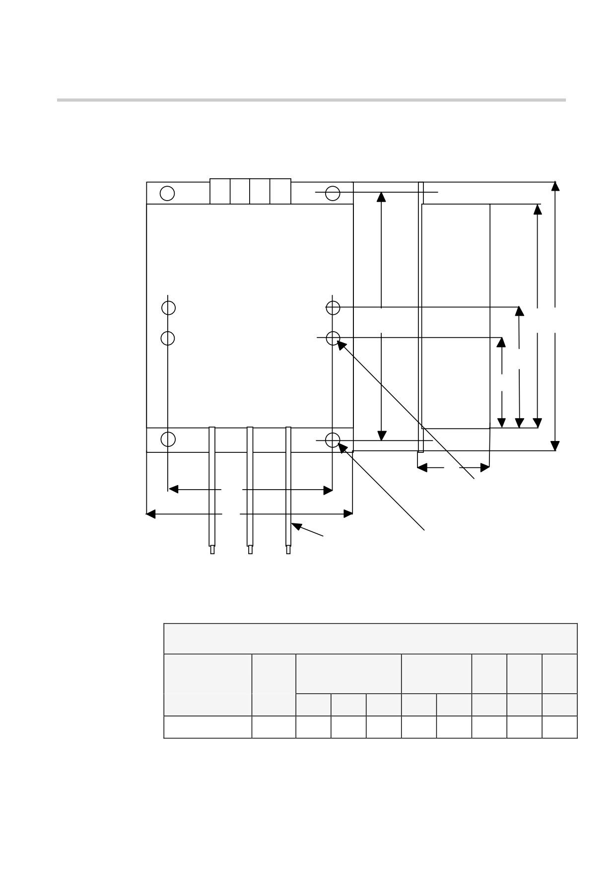
Figure 4.3 Product Mechanical Arrangement
Allow 50mm above and below product for cooling. Allow 8cm
access to one side of the unit. Mount the unit with the cover in place.
A
D
C
B
DIN RAIL MOUNTING
PANEL
MOUNTING
Mounting clip can be easily
pushed to allow different
USE M4 FIXINGS
F
mounting configurations
E
506/507/508 - HA389427
Installing the 506/507/508
4-7
IP20
DIM
506
507
508
A
80 mm
80 mm
90 mm
B
84 mm
84 mm
84 mm
C
140 mm
140 mm
140 mm
D
105 mm
105 mm
105 mm
E
50 mm
50 mm
50 mm
F
140 mm
140 mm
140 mm
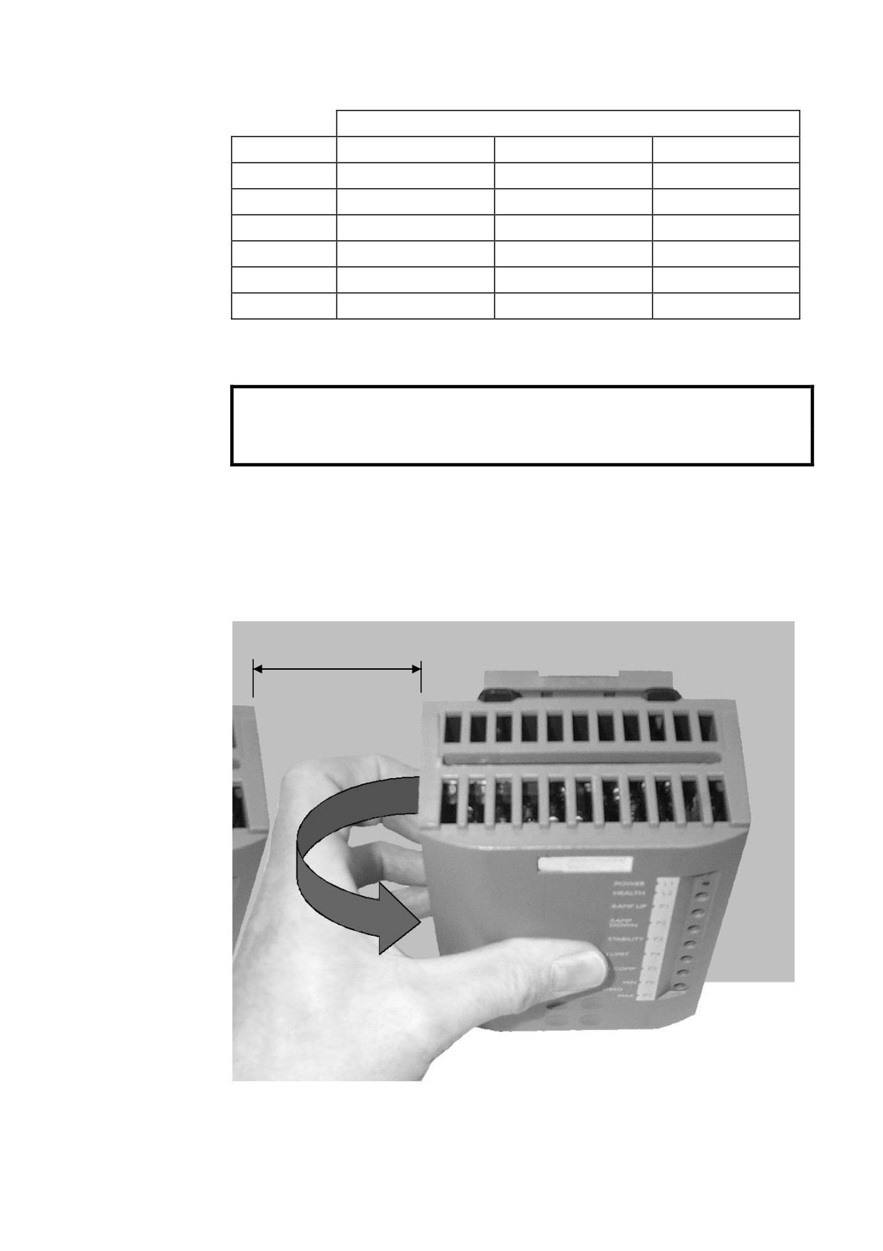
Removing the Cover
WARNING!
Isolate the controller before fitting or removing the cover.
Remove the cover to access the terminals and switches.
It is removed easily when the unit is mounted on the backplate.
There are no screw fixings. It snaps back on to the front of the drive.
8cm
506/507/508 - HA389427
4-8 Installing the 506/507/508
Filter
Figure 4.4 Filter Mechanical Arrangement
LINE
L2
L1
PE
PE
END USER TO AFFIX
E
F
B
OWN DIN RAIL HERE
TO MOUNT DRIVE
H
G
C
4 x M5 Inserts for
D
DIN Rail Mounting
A
at chosen height
2
200mm
4 Holes M6 Clearance
LOAD
Flying Leads
L2
L1
PE
Terminals Suitable for
Black Red
Green/
4mm2 /12AWG Cable
Yellow
506/507/508
Filter
Watt
Overall
Fixing
Loss*
Dimensions
Centres
A
B
C
D
E
F
G
H
CO389115
9.5W
100
159
55
84
147
135
63
78
Note: * Note:- Watt Loss value is at a current output of 12 Amps dc.
506/507/508 - HA389427
Installing the 506/507/508
4-9
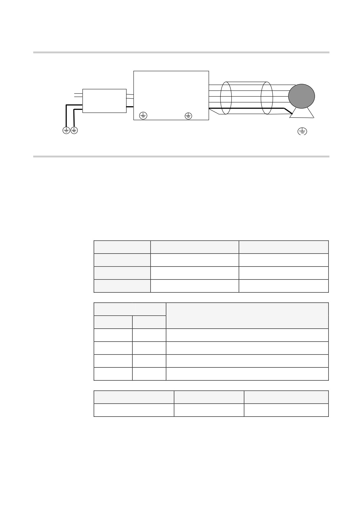
EMC Connections
Figure 4.5 Wiring Diagram Mains Filter
Screened Cable
DC Motor
Product
F+
F-
AC Supply
L1
A+
Filter
L2
A-
Grd (PE)
Grd (PE)
Grd (PE)
PE
Installation and Set-Up
Warning
Before applying power check:-
Switch Selection
(a) Mains switch set to intended supply voltage, Left 110/120,
Right 220/240
(b) Personality switches.
SW1
OFF
ON
506
0.25 to 3A
0.5 to 3A
507
0.5 to 3A
1 to 6A
508
1 to 6A
2 to 12A
Speed
Range
Maximum Feedback Voltage Range
SW2
SW3
Armature or Tacho
OFF
OFF
15 to 30
ON
OFF
30 to 60
OFF
ON
60 to 120
ON
ON
120 to 180
SW4
OFF
ON
FEEDBACK
TACH
ARMATURE
506/507/508 - HA389427
4-10 Installing the 506/507/508
Note: Even when intending to utilise tachogenerator feedback it may
be wise to initially run under armature control. Set feedback
voltage switches accordingly. Note that if this procedure is
followed the tachogenerator must be temporarily disconnected
as it will affect operation of the controller.
Potentiometer
(a)
Product
Default
P1 Ramp Up
Anti-clockwise
P2 Ramp Down
Anti-clockwise
P3 Stability
Mid
P4 I Limit
Anti-clockwise
P5 IR Comp
Anti-clockwise
P6 Min Speed
Anti-clockwise
P7 Max Speed
Mid.
(b)
External
Speed setpoint to minimum.
Motor
(a)
Check motor is compatible with controller and settings.
(b)
Check motor and load are free to rotate.
Wiring
(a)
Check there is no loose wire ends on the PCB.
(b)
Check that there are no free wire ends on external controls
liable to contact grounded metal or earth (ground) referenced
parts.
Applying Power
1.
Power on LED 1 should illuminate.
2.
Close “RUN” contact and apply a small speed setpoint (5%).
Armature current should now flow, the motor should turn and run at
a fixed speed.
If the motor runs above 5% up to top speed Open Run Contact.
If the controller is in “Armature” Control then excess speed is due to
incorrect setting of SW2 and 3, the speed scaling.
506/507/508 - HA389427
Installing the 506/507/508
4-11
If the controller is in “Tacho” control then excess speed is due to
incorrect polarity of feedback. Alter wiring as follows:-
Problem
Action
Direction correct but
Reverse Tachogenerator polarity only.
overspeeding.
Direction incorrect and
overspeeding.
Reverse field polarity only.
If motor does not run, increase Ilimit potentiometer P4 as current
may be insufficient for rotation. The Health light LED2 may light in
this condition after 15 seconds indicating a Stall, remove and reapply
power to reset condition.
If the motor is in control but runs in the wrong direction either:-
(a) Armature Control - Reverse Field Polarity.
(b) Tacho Control - Reverse Field AND Tacho Polarity.
3.
Increase speed setpoint to maximum and check armature voltage
does not exceed rated value, adjust maximum speed using P7. If a
minimum speed setting is required reduce speed setpoint
potentiometer to zero adjust minimum speed potentiometer P6 to
give required value. With speed setpoint at maximum, re-adjust
maximum speed with P7.
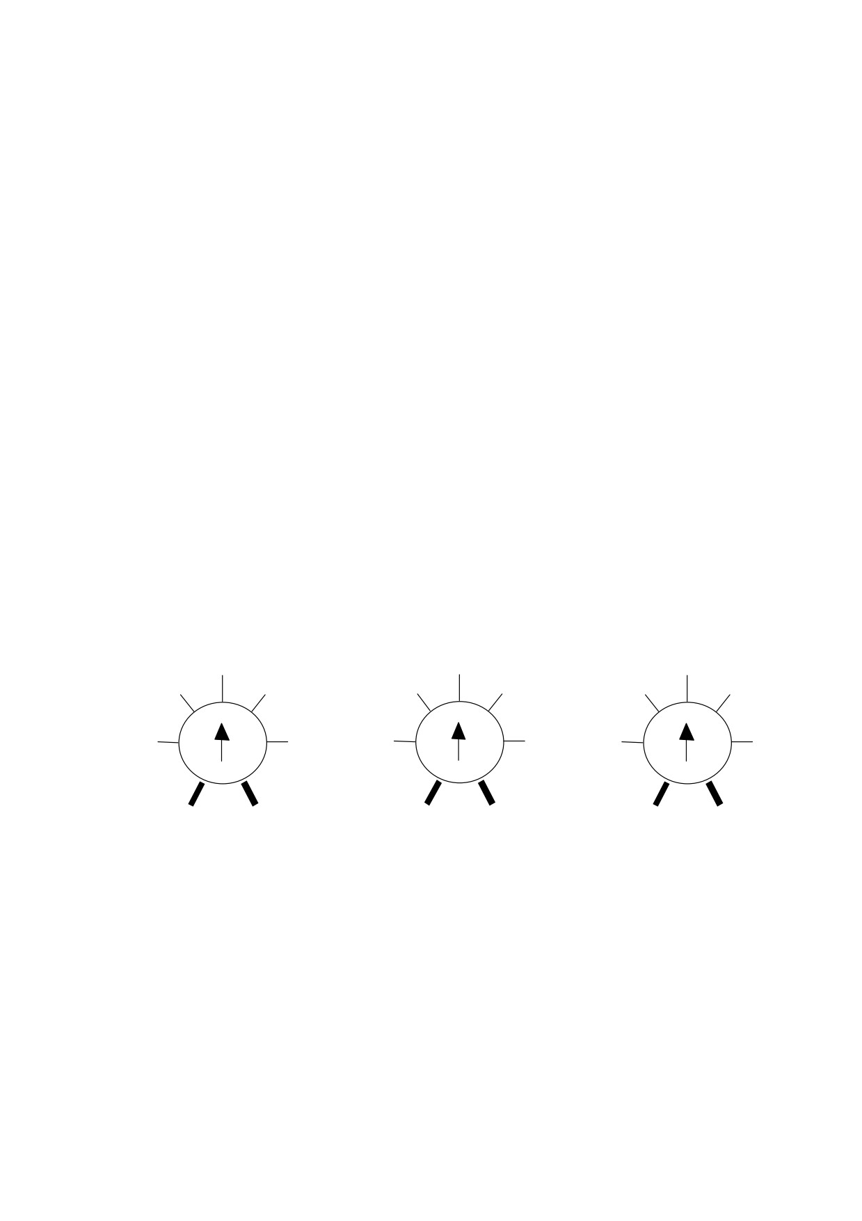
4.
Adjust I Limit potentiometer to suit Motor Current Rating.
1.75
3.5
7
(0.75)
(1)
(1.5)
(2)
(3)
(4)
1.5
2
3
4
6
8
(0.5) 1
2.5
(1.25)
(1)
2
5 (2.5)
(2) 4
10 (5)
0.5
3
1
6
2
12
(0.25)
(1.5)
(0.5)
(3)
(1)
(6)
506
507
508
More accurate adjustment may be achieved by inserting a meter in
the armature circuit.
5.
Adjust Ramp Up P1 and Ramp Down P2 potentiometers as required.
6.
In Armature Voltage Feedback, speed droop will occur as load is
applied. Adjust IR compensation P5 to reduce this effect. Excessive
adjustment may cause instability.
7.
It may be necessary to adjust the Speed Stability Potentiometer P3 to
improve speed response. Excessive adjustment may cause
instability.
506/507/508 - HA389427

4-12 Installing the 506/507/508
Fault Finding
Problem
Possible Cause
Remedy
Controller will not
Wrong supply voltage.
Check setting on mains switch.
power up - no ‘on’
It is likely that if too high a
indication.
voltage has been used the
Controller will be permanently
Line fuses blown (if
damaged.
fitted).
Power off, check circuits and
replace fuses.
Motor will not turn.
No run circuit.
Check run contact and wiring.
No setpoint.
Check connections to and
operation of setpoint
potentiometer.
Motor accelerates out
Tacho polarity.
Power off and reverse tacho
of control with tacho-
connections.
generator feedback
Tacho linkage.
Check tacho coupling to motor.
and small setpoint.
Tacho faulty.
Remove and replace tacho.
Motor rotates in the
Motor connections are
wrong direction.
wrong for required
Speed is controlled
direction with:
though.
1. Armature voltage
Power off and reverse armature
feedback.
connections.
2. Tacho-generator
Power off and reverse both
armature and tacho
connections.
Motor will not turn
Motor shaft locked or
Power off and check motor and
and the stall light
jammed.
load for stiffness or jamming.
comes on after 15
No field current (not
Check that DC voltage across
seconds in speed
applicable for
motor field terminals is present.
control mode.
permanent magnet
If not power off and check field
motors).
circuit for continuity.
No armature current.
Power off and check armature
circuit for continuity.
Low current limit.
Check current limit with +10V
link on Controller.
Motor will only run at
Maximum speed
Check connections to and
full speed.
setpoint.
operation of setpoint
potentiometer.
506/507/508 - HA389427

Installing the 506/507/508
4-13
Problem
Possible Cause
Remedy
Motor will not run at
Wrong speed range
Refer to Installation and Set-up
correct maximum
selection on preset
chapter.
speed.
switches.
Stall light comes on
Incorrect wiring of run
Run contact should be wired
after 15 seconds in
contact.
between the two terminals
current control mode.
marked ‘run’ and ‘+10V’.
Stall light comes on
Faulty or incorrect
Check motor armature
immediately after the
load across the ‘A+’
thoroughly. The Controller
‘run’ contact is closed.
and ‘A-’ terminals.
should not be used on motors
with a low inductance.
506/507/508 - HA389427
5-1
Routine Maintenance & Repair
Chapter 5 ROUTINE MAINTENANCE AND REPAIR
Routine Maintenance
Periodically inspect the motor speed controller for build-up of dust
or obstructions that may affect ventilation of the unit. Remove this
using dry air.
Repair
There are no user-serviceable components.
IMPORTANT: MAKE NO ATTEMPT TO REPAIR THE UNIT - RETURN IT TO
PARKER SSD DRIVES.
Returning the Unit to Parker SSD Drives
Please have the following information available:
• The model and serial number - see the unit’s rating label
• Details of the fault
Contact your nearest Parker SSD Drives Service Centre to arrange
return of the item.
You will be given a Returned Material Authorisation. Use this as a
reference on all paperwork you return with the faulty item. Pack and
despatch the item in the original packing materials; or at least an
antistatic enclosure. Do not allow packaging chips to enter the unit.
506/507/508 - HA389427
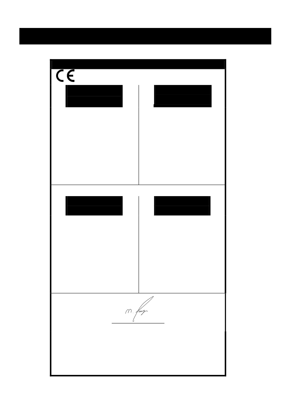
EMC Certification 6-1
Chapter 6 EMC CERTIFICATION FOR 506/507/508
Certificates
506/507/508
EC DECLARATIONS OF CONFORMITY
Date CE marked first applied: 01.04.2000
EMC Directive
Low Voltage
Directive
Issued for
The drive is CE
In accordance with the EEC Directive
In accordance with the EEC Directive
compliance with
marked in
the EMC
2004/108/EC
2006/95/EC
accordance with the
Directive when
low voltage
We Parker Hannifin Manufacturing Limited,
We Parker Hannifin Manufacturing Limited,
the unit is used
directive for
address as below, declare under our sole
address as below, declare under our sole
as relevant
electrical
responsibility that the above Electronic
responsibility that the above Electronic
apparatus.
equipment and
Products when installed and operated with
Products when installed and operated with
appliances in the
reference to the instructions in the Product
reference to the instructions in the Product
voltage range
Manual (provided with each piece of
Manual
when installed
equipment) is in accordance with the relevant
(provided with each piece of equipment), is in
correctly.
clauses from the following standard:-
accordance with the relevant clauses from the
following standard :-
* BSEN61800-3 (2004)
EN50178 (1998)
MANUFACTURERS DECLARATIONS
EMC
Machinery
Declaration
Directive
This is provided
Since the potential
We Parker Hannifin Manufacturing
The above Electronic Products
to aid your
hazards are mainly
Limited, address as below, declare under our
are components to be incorporated into
justification for
electrical rather
sole responsibility that the above Electronic
machinery and may not be operated alone.
EMC
than mechanical,
Products when installed and operated with
The complete machinery or installation using
compliance
the drive does not
reference to the instructions in the Product
this equipment may only be put into service
when the unit is
fall under the
Manual (provided with each piece of
when the safety considerations of the Directive
used as a
machinery
equipment) is in accordance with the relevant
2006/42/EC are fully adhered to.
component.
directive. However,
clauses from the following standard:-
Particular reference should be made to
we do supply a
EN60204-1 (Safety of Machinery - Electrical
manufacturer's
Equipment of Machines).
* BSEN61800-3 (2004)
declaration for
All instructions, warnings and safety
when the drive is
information of the Product Manual must be
used (as a
adhered to.
component) in
machinery.
Dr Martin Payn (Conformance Officer)
* Compliant with the immunity requirements of the Standard without specified EMC filters.
Parker Hannifin Manufacturing Limited, Automation Group, SSD Drives Europe,
New Courtwick Lane, LITTLEHAMPTON, WEST SUSSEX BN17 7RZ
TELEPHONE:
+44(0)1903 737000 FAX:
+44(0)1903 737100
Registered Number:
4806503 England. Registered Office: 55 Maylands Avenue, Hemel Hempstead, Herts HP2 4SJ
506/507/508 - HA389427
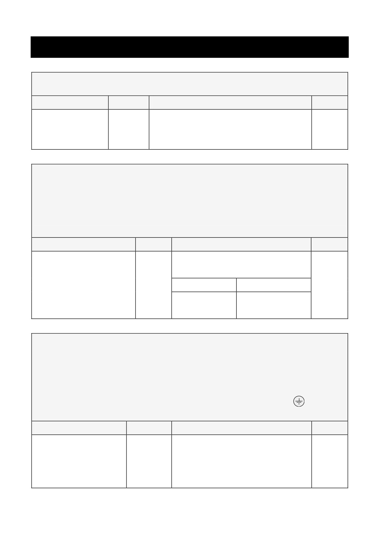
7-1
Technical Specifications
Chapter 7 TECHNICAL SPECIFICATIONS
Input Supply
Parameter
Symbol
Value
Units
Frequency
50/60 ± 10%
Hz
Voltage
Vs
110/120 ±10% or 220/240 ± 10%
V
(Earth (TN) or non-earth (IT) referenced)
Speed Control
(1)
Range selected by built in switches.
(2)
With IR comp setting optimised.
(3)
Consideration must be given to the motor at it may overheat
at low speed.
Parameter
Symbol
Value
Units
Stall detect time
15 maximum 20 typical
s
Type of controller
Variable proportional plus integral
Feedback method (1)
Va
Tacho
0-100% load regulation
2(2) (typically)
0.1 (typically)
Max. torque speed range
20:1
100:1 (3)
%
Current (Torque) Control
(1)
Range selected by built in switches.
(2)
Suitable for armature time constants not less than 5ms.
(3)
All control terminals are at a potential of the peak of the
input supply with respect to earth (ground) .
All cables should be rated for this voltage.
Parameter
Symbol
Value
Units
Overspeed limiting (1)
Standard (1)
Type of controller (2)
Fixed proportional plus integral
Feedback method
Non-isolated shunt (3)
Linearity
2
%
506/507/508 - HA389427
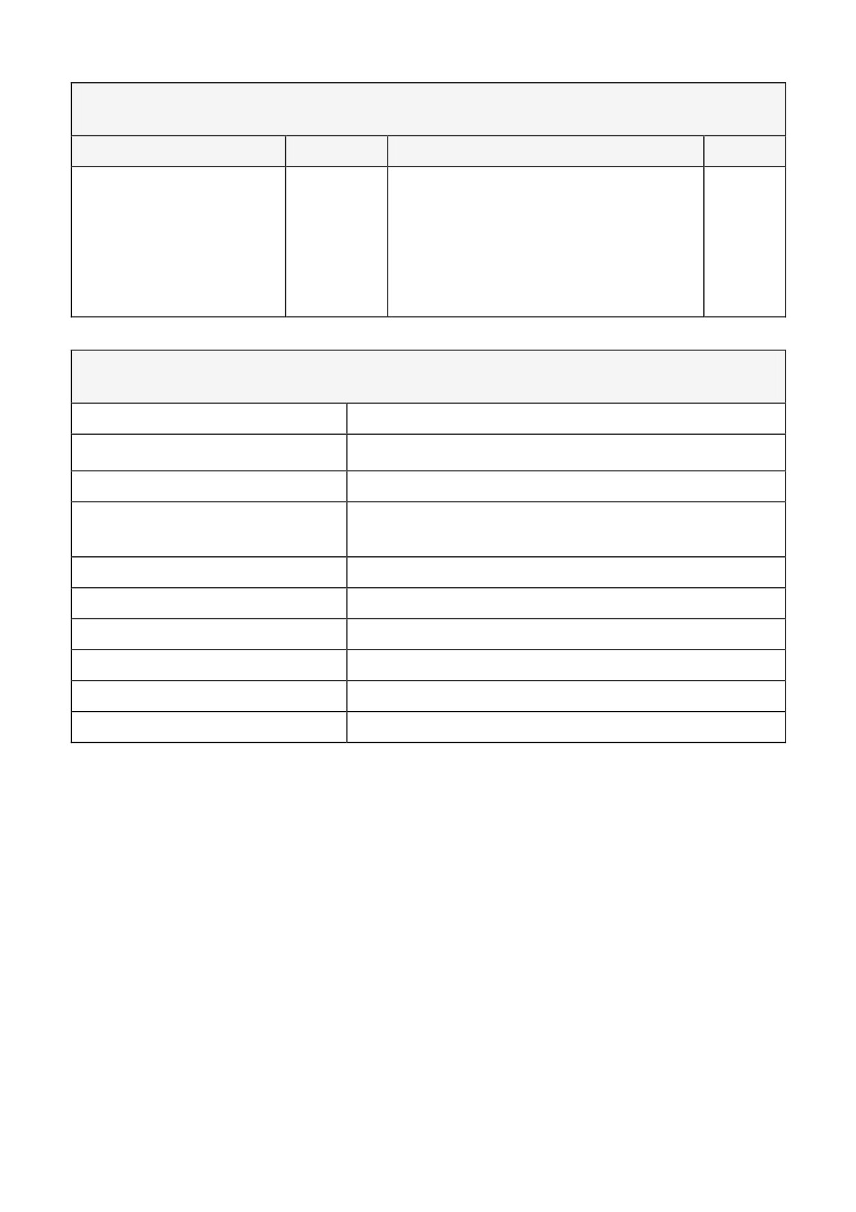
Technical Specifications
7-2
Adjustment Range
Parameter
Symbol
Value
Units
Armature loss comp.
IR comp
0 - 25% of Va
Maximum speed
N max
100% ± 25%
Minimum speed
N min
0 - 25% of N max
%
Ramp up time
Ramp
1 - 15 (minimum)
s
Ramp down time
Ramp
1 - 15 (minimum)
s
Environmental Requirements
Operating Temperature
0 to +40oC (Derate 1.5% / Degree above 40oC)
Max. Operating Temperature
50oC
Humidity
85% R.H. at 40oC (non condensing)
Altitude
Above 1000m derate at 1% / 100m to a
maximum of 2000m
Atmosphere
Non-flammable, non-corrosive and dust free
Storage Temperature Range
-25oC to +55oC
Transport Temperature Range
-25oC to +55oC
Enclosure
IP2X suitable for cubicle mounting
Installation Category
Overvoltage Category III.
Pollution
Pollution Degree 2.
506/507/508 - HA389427
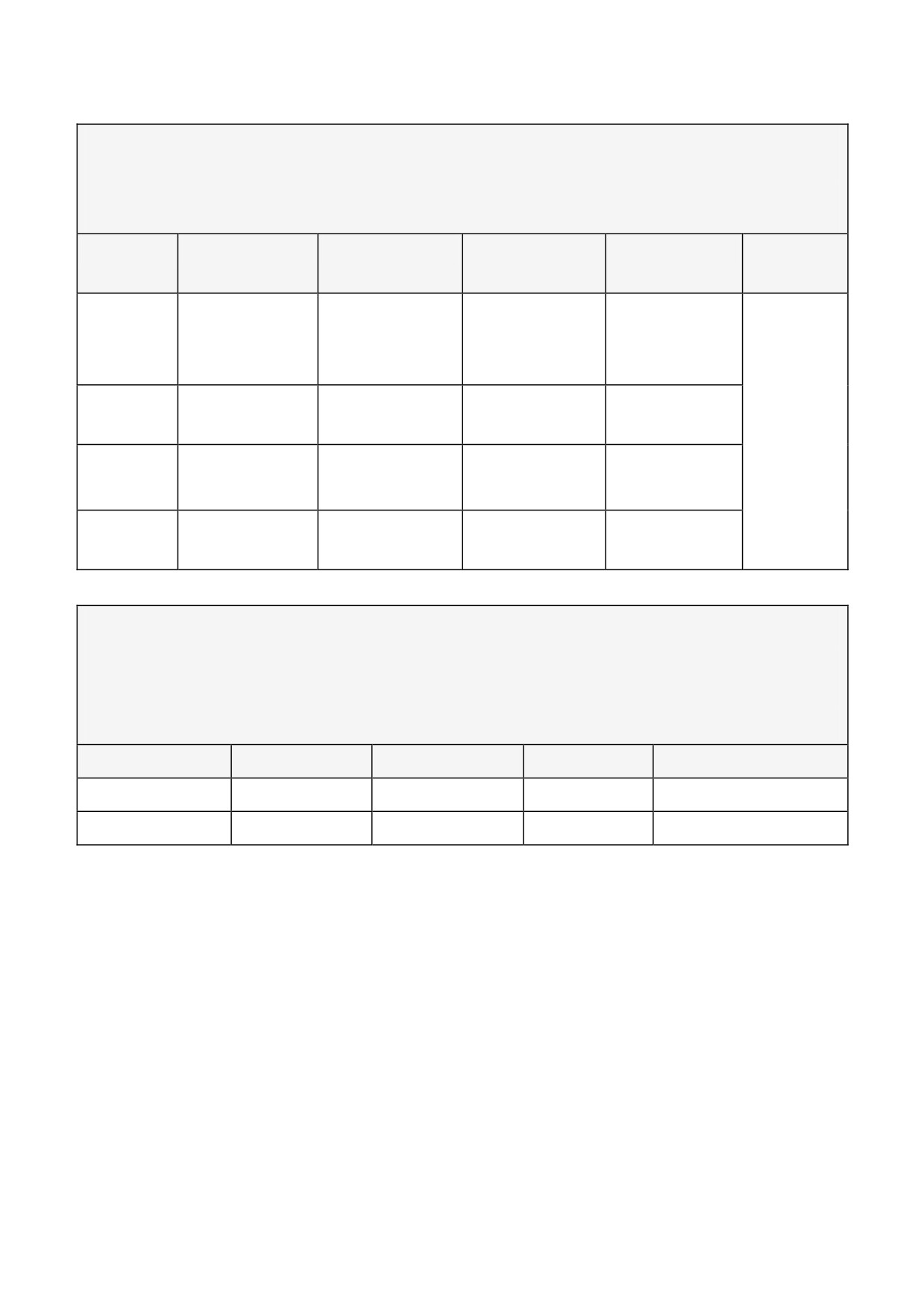
7-3
Technical Specifications
EMC Technical Ratings
Immunity
Port
Phenomenon
Test Standard
Level
Criterion
Generic
Standard
Enclosure
ESD
BS EN61000-
8kV AD
Self Recovery
EN50082
Port
4-2(1995)
-1
RF Field
10V/m,1kHz
No Change
AM
(1992),
Power
Fast Transient
BS EN61000-
2kV
Self Recovery
and
Ports
Burst
4-4(1995)
EN50082
Signal &
Fast Transient
BS EN61000-
2kV
Self Recovery
-2
Control
Burst
4-4(1995)
(1995)
Power
Fast Transient
BS EN61000-
2kV
Self Recovery
Interfaces
Burst
4-4(1995)
Emissions
These levels of performance are achieved when installed as
specified with the recommended Supply Filter.
* Achieved with up to 50m of motor cable.
Port
Phenomenon
Test Standard
Level
Generic Standard
Enclosure Port
Radiated
EN55011
Class B
EN50081-1 (1992)
Power Port
Conducted
EN55011
Class B*
EN50081-2 (1994)
506/507/508 - HA389427
Technical Specifications
7-4
Electrical Ratings
Output Ratings with typical armature voltage,
Va, 80/90V (160/180V)
(1)
Range selected by built in switches.
(2)
When the controller is energised the dc motor shunt field is
permanently energised. It is the responsibility of the installer
to ensure that this is not detrimental to the long term
reliability of the dc motor.
Parameter
506
507
508
Maximum Armature Output
1.5A
3A
3A
6A
6A
12A
Current (IA) (1)
Typical Motor Horsepower (Hp)
90V Armature (110/120V AC)
1/10
1/6
1/6
1/3
1/3
3/4
180V Armature (220/240V AC)
1/6
1/3
1/3
3/4
3/4
2
Typical Motor Power (kW)
90V Armature (110/120V AC)
0.07
0.125
0.125
0.25
0.25
0.55
180V Armature (220/240V AC)
0.125
0.25
0.25
0.55
0.55
1.5
Controller loss (W)
5
10
10
20
20
40
Maximum AC Supply Current
3
4.5
6
9
12
18
(ls,A rms)
Maximum l2t for fusing (A2s)
36
36
80
80
365
365
Maximum form factor (ls/la)
2
1.5
2
1.5
2
1.5
Maximum Field Current (2)
2
(If, A dc)
Field Voltage (0.9 x Vs) V dc
V
110/120V AC
90-100
220/240V AC
180-200
Adjustment Ranges
Range selected by built in switches.
Parameter
506
507
508
Maximum current * (l max, A)
0.25 - 3
0.5 - 6
1 - 12
506/507/508 - HA389427
7-5
Technical Specifications
Product Code
Block
Product
Code
Feature
1
Basic Product
506
3 Amp
507
6 Amp
508
12 Amp
2
Livery
00
Standard
01 to 99
Customer
3
Cover
20
IP20 Cover
4
Special Options
00
Standard
01 to 99
Documented Special Options