Parker Operation Manual Series D*FB / D*1FB with Integrated Electronics (2013)
Bulletin HY11-5715-669/UK
Operation Manual
Series D*FB / D*1FB with
Integrated Electronics
D*FB Design ³ 12
D*1FB Design ³ 10
Proportional Directional
Control Valve
Parker Hannifin
Manufacturing Germany GmbH & Co. KG
Hydraulic Controls Division Europe
Gutenbergstr. 38
41564 Kaarst, Germany
Tel.: (+49) 181 99 44 43 0
E-mail: infohcd@parker.com
Copyright © 2013, Parker Hannifin Corp.
Prop. Directional Control Valve
Operation Manual
Series D*FB / D*1FB
Note
This document and other information from Parker-Hannifin Corporation,
its subsidiaries and authorized distributors provide product or system
options for further investigation by users having technical expertise.
The user, through its own analysis and testing, is solely responsible for
making the final selection of the system and components and assuring
that all performance, endurance, maintenance, safety and warning re-
quirements of the application are met. The user must analyze all aspects
of the application, follow applicable industry standards, and follow the
information concerning the product in the current product catalog and in
any other materials provided from Parker or its subsidiaries or authorized
distributors.
To the extent that Parker or its subsidiaries or authorized distributors
provide component or system options based upon data or specifications
provided by the user, the user is responsible for determining that such
data and specifications are suitable and sufficient for all applications and
reasonably foreseeable uses of the components or systems.
2
Parker Hannifin Corporation
Hydraulics Group
Prop. Directional Control Valve
Operation Manual
Series D*FB / D*1FB
Chapter
Page
1.
Introduction
4
Order Code D*FB
4
Order Code D*1FB
5
Name Plate Example
6
Block Diagram of Integral Electronics
6
Characteristics of Valve Driver
6
Technical Data
7
Signal Flow Diagram
8
2.
Safety Instructions
9
Symbols
9
Marking, Name Plates
9
Work at the Valve
9
3.
Important Details
9
Intended Usage
9
Common Instructions
9
Liability
9
Storage
9
4.
Mounting / Installation
10
Scope of Supply
10
Mounting
10
Operation Limits
10
Pressure Fluids
10
Electrical Connection
11
Electrical Interfacing
12
5.
Operation Instructions
18
ProPxD parameterizing software
18
Screenshot
18
Hardware requirements
18
Cable Specification
18
Parametrizing connection
19
Parametrizing cable
19
Program Installation
19
Software Operating
19
Parameter overview for basic mode
21
Individual Description of Basis-Parameters
22
Parameter overview for expert mode
23
Individual Description of Expert Parameters
23
Error messages
24
Air Bleeding of Hydraulic System
25
Filter
25
Flushing
25
6.
Maintenance
25
7.
Trouble Shooting
26
8.
Accessories / Spare Parts
27
Accessories
27
Spare Parts
27
3
Parker Hannifin Corporation
Hydraulics Group
Prop. Directional Control Valve
Operation Manual
Series D*FB / D*1FB
1. Introduction
D*FB
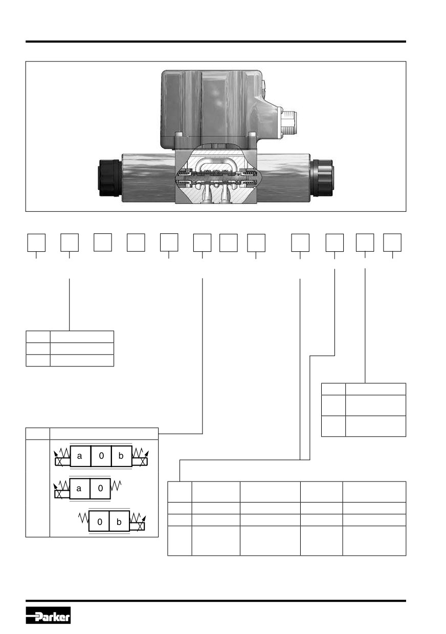
Ordering Code D*FB
D
F
B
0
N
Direct.
Nominal
Spool-
Spool
Seal
Command-
Option
Design
Design
control
size
type
position
NBR
signal
series
valve
(see
(different seal
catalogue)
compound by
request)
Code
Nominal size
1
NG06 / CETOP 3
3
NG10 / CETOP 5
Code
Design
Spool/sleeve
0
design
Spool/body
3
design
Code
Spool position
C
E
Command
Code
Function
Connection
Option
signal
F0
0...+/-10V
0...+10V > P-A
6 + PE
Pot.-supply
K
S0
4...20mA
12...20mA > P-A
6 + PE
-
Pot.-supply &
0...+/-10V
0...+10V > P-A
W5 1)
11 + PE
command preset
4...20mA
12...20mA > P-A
channel
1) Factory set +/-10V
4
Parker Hannifin Corporation
Hydraulics Group
Prop. Directional Control Valve
Operation Manual
Series D*FB / D*1FB
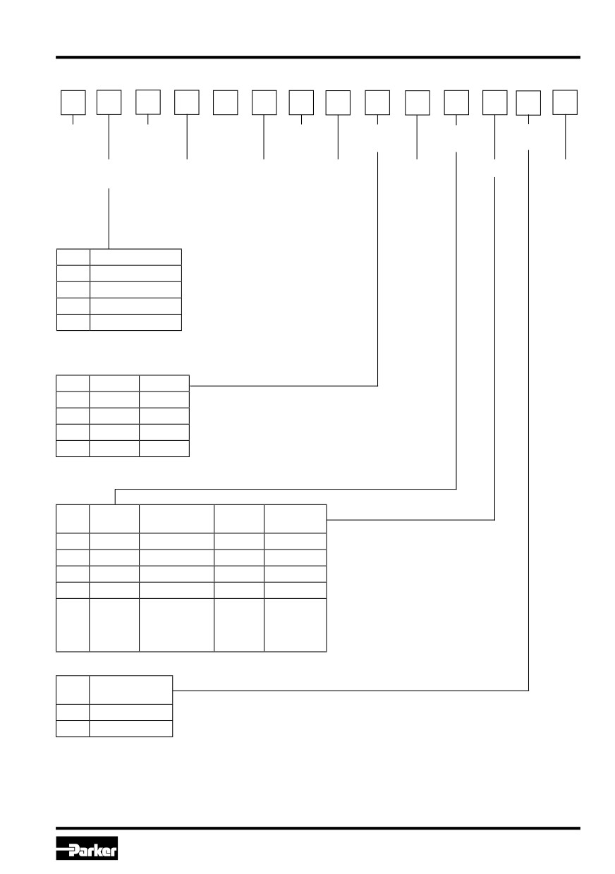
Ordering Code D*1FB
D
1
F
B
C
N
Direct.
NG06
Flow
Pilot
Command
Valve
control
pilot *
(see
connection
signal
accessories
catalogue)
valve
Nominal
Proportional
Spool
Spool
Seal
Option
Design
size
control
type
position
NBR
series
(see
(other seal
catalogue)
compound
on request)
Code
Nominal size
3
NG10 / CETOP05
4
NG16 / CETOP07
9 1)
NG25 / CETOP08
11
NG32 / CETOP10
1) with enlarged connections
Ø 32 mm
Code
Inlet
Drain
1
internal
external
2
external
external
4
internal
internal
5
external
internal
Command
Connec-
Code
Function
Option
signal
tion
F0
0...±10V
0...+10V > P-B
6 + PE
Pot.-supply
M0
0...±10V
0...+10V > P-A
6 + PE
Pot.-supply
S0
4...20mA
12...20mA > P-A
6 + PE
—
G0
0...±20mA
0...+20mA > P-B
6 + PE
—
Pot.-supply
0...±10V
0...+10V > P-A
& command
W5
11 + PE
4...20mA
12...20mA > P-A
preset
channels
Valve
Code
accessories
0
Standard
8
Monitor switch
* as D1FV* separately available
5
Parker Hannifin Corporation
Hydraulics Group
Prop. Directional Control Valve
Operation Manual
Series D*FB / D*1FB
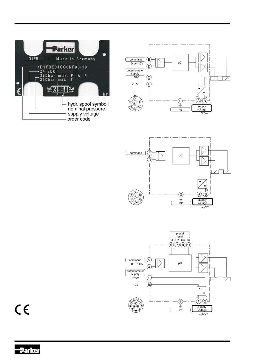
Name Plate Example
Block Diagram of Integral Electronics
Code F0/M0 (6+PE)
18
Parker D*FB/D*1FB proportional directional control
Code S0/G0 (6+PE)
valves have an integral electronic and requires only
one sole electrical common for the control system.
Different flow sizes, as well as command signal op-
tions are available to achieve an optimal adaption
S0: 4...12...20mA
for different applications.
G0: 0...±20mA
Characteristics of Valve Driver
The described integral electronic driver combines
all necessary functions for the optimal operation of
the valve. The most important features are:
• digital circuit design
• high dynamic constant current solenoid control
18
• differential input stage with various command
signal options
• four quadrant ramp function
Code W5 (11+PE)
• MIN adjustment for deadband compensation
• MAX adjustment to match the command signal
span to the valve operating range
• optional reference outputs +/- 10 V for potentio-
meter supply
• optional four parametrizable preset recall chan-
nels
• standard central connection
• compatible to the relevant European EMC-
standards
• comfortable interface program
18
6
Parker Hannifin Corporation
Hydraulics Group
Prop. Directional Control Valve
Operation Manual
Series D*FB / D*1FB
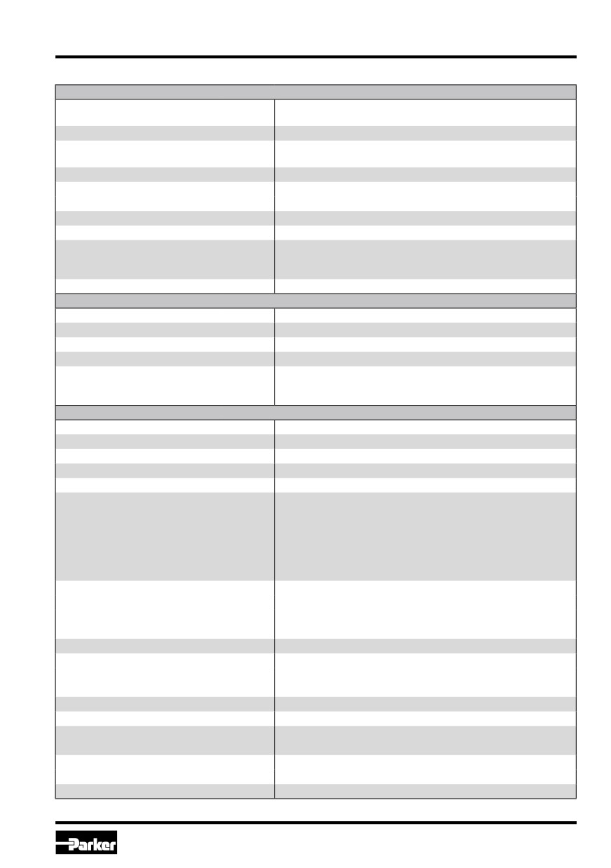
Technical Data
General
Model
Proportional directional control valve, direct operated (D*FB), pi-
lot operated (D*1FB)
Drive
Proportional solenoid
Mounting Pattern
NG6 (CETOP 3) / NG10 (CETOP 5)
NG16 (CETOP 7) / NG25 (CETOP 8) / NG32 (CETOP 11)
Installation Position
Any
Hysteresis
D1FB*0/D3FB*0
[%]
< 4
D3FB*3/D*1FB
[%]
< 5
Ambient Temperature Range
[°C]
-20...+60
Protection Class
NEMA 4 (IP 65) acc. EN 60529
Vibration Strength
[G]
10 Sinus 5...2000 Hz acc. IEC 68-2-6
30 Random noise 20...2000 Hz acc. IEC 68-2-36
15 Shock acc. IEC 68-2-27
Weight
[kg]
NG6: 3 / NG10: 7 / NG16: 11 / NG25: 19.5 / NG32: 61
Hydraulic
Fluid
Hydraulic oil according to DIN 51524...535, other on request
Viscosity permitted
[cSt]/[mm2/s]
20...400
Fluid Temperature
[°C]
-20...+60 (NBR: -25...+60)
Filtration
ISO 4406 (1999); 18/16/13
Operating Pressure max. (D*FB)
[bar]
350 for ports P, A, B / 210 for port T
Pilot oil intern (D*1FB):
[bar]
350 for ports P, A, B, X / 185 for T, Y
Pilot oil extern (D*1FB):
[bar]
350 for ports P, A, B, T, X / 185 for Y
Electrical
Duty Ratio
[%]
100
Supply Voltage
Us
[VDC]
18...30, ripple < 5% eff., surge free
Current Consumption max.
[A]
D1FB: 1.5 / D3FB: 2.0 / D*1FB: 1.5
Pre-Fusing
[A]
D1FB: 2.0 / D3FB: 2.5 / D*1FB: 2.0
Potentiometer supply
Up
[V]
± 10 / ± 5 % max. 10 mA
Command Signal Options
Uc
[V]
Codes F0, M0, W5: +10...0...-10, ripple < 0.01 % eff., surge free,
Ri = 100 kOhm
Ic
[mA]
Codes S0 & W5: 4...12...20, ripple < 0.01 % eff., surge free,
Ri = 200 Ohm
< 3.6 mA = enable off, > 3.8 mA = enable on (acc. NAMUR NE43)
[mA]
Code G0: +20...0...-20, ripple < 0.01 % eff., surge free,
Ri = 200 Ohm
Differential Input Voltage max.
[V]
Codes F0, M0, S0, G0: 30 for terminal D and E against PE (terminal G)
[V]
11 for terminal D and E against 0V (terminal B)
[V]
Code W5: 30 for terminal 4 and 5 against PE (terminal PE)
[V]
11 for terminal 4 and 5 against 0V (terminal 2)
Channel Recall Signal
Uch
[V]
0...2.5: Off / 5...30: On / Ri = 100 kOhm
Adjustment Ranges
Min
[%]
0...50
Max
[%]
50...100
Ramp
[s]
0...32.5
Interface
RS 232C, parametrizing connection 5pole
EMC
EN 61000-6-2, EN 61000-6-4
Central Connection
Codes F0, M0, S0, G0: 6 + PE acc. EN 175201-804
Code W5: 11 + PE acc. EN 175201-804
Cable Specification
[mm²]
Codes F0, M0, S0, G0: 7 x 1.0 (AWG16) overall braid shield
[mm²]
Code W5: 11 x 1.0 (AWG16) overall braid shield
Cable Length max.
[m]
50
7
Parker Hannifin Corporation
Hydraulics Group
Prop. Directional Control Valve
Operation Manual
Series D*FB / D*1FB
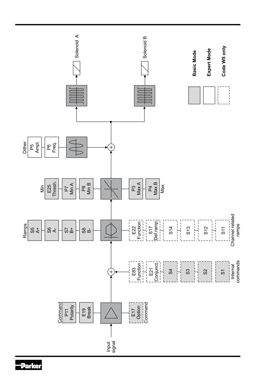
Signal flow diagram
8
Parker Hannifin Corporation
Hydraulics Group
Prop. Directional Control Valve
Operation Manual
Series D*FB / D*1FB
2. Safety Instructions
Common Instructions
Please read the operation manual before installa-
We reserve the right for technical modifications of
tion, startup, service, repair or stocking! Paying no
the described product. Illustrations and drawings
attention may result in damaging the valve or in-
within this manual are simplified representations.
corporated system parts.
Due to further development, improvement and
modification of the product the illustrations might
Symbols
not match precisely with the described valve. The
This manual uses symbols which have to be fol-
technical specifications and dimensions are not
binding. No claim may resulting out of it. Copy-
lowed accordingly:
rights are reserved.
Instructions with regard to the warranty
Liability
Instructions with regard to possible dama-
The manufacturer does not assume liability for dam-
ging of the valve or linked system compo-
age due to the following failures:
nents
• incorrect mounting / installation
• improper handling
Helpful additional instructions
• lack of maintenance
• operation outside the specifications
Marking, Name Plates
Instructions applied on the valve, i.e. wiring dia-
Do not disassemble the valve! In case of sus-
grams and name plates, must be observed and
picion for a defect please return the valve to
maintained legibly.
the factory.
Work at the Valve
Storage
Workings in the area of installation, commission-
In case of temporary storage the valve must be
ing, maintenance and repair of the valve may only
protected against contamination, atmospheric ex-
be allowed by qualified personnel. This means per-
posure and mechanical damages. Each valve has
sons which have, because of education, experience
been factory tested with hydraulic oil, resulting in
and instruction, sufficient knowledge on relevant di-
protection of the core parts against corrosion. Yet
rectives and approved technical rules.
this protection is only ensured under the following
conditions:
3. Important Details
Intended Usage
Storage
Storage requirements
This operation manual is valid for proportional di-
period
rectional control valves D*FB/D*1FB series. Any dif-
constant humidity < 60% as well
12 months
ferent or beyond it usage is deemed to be as not
as constant temperature < 25°C
intended. The manufacturer is not liable for warran-
varying humidity as well as
ty claims resulting from this.
6 months
varying temperature < 35°C
Outdoor storage or within sea and tropical cli-
mate will lead to corrosion and might disable
the valve!
9
Parker Hannifin Corporation
Hydraulics Group
Prop. Directional Control Valve
Operation Manual
Series D*FB / D*1FB
4. Mounting / Installation
Parker offers bolt kits:
D1FB: BK375, D3FB: BK385, D31FB: BK385,
Scope of Supply
D41FB: BK320, D91FB: BK360, D111FB:
Please check immediately after receiving the valve,
BK386
if the content is matching with the specified scope
• Tighten the bolts crisscross with the following
of supply. The delivery includes:
torque values:
• valve
D1FB: 7.6 Nm / D3FB: 13.2 Nm
• operation manual
D31FB: 13.2 Nm, D41FB: 13 (63) Nm, D91FB:
The central connector assembly as well as the pa-
108 Nm, D111FB: 517 Nm
rametrizing cable has to be ordered separately and
are not included in the delivery.
Insufficient condition of the valve mounting
surface migth create malfunction!
Please check the delivery immediately after
Incorrect mounting resp. bolt torque may re-
receiving the shipment for apparent damages
sult in abrupt leakage of hydraulic fluid on the
due to shipping. Report shipment losses at
valve ports.
once to the carrier, the insurance company
and the supplier!
Operation Limits
Mounting
The valve may be operated within the determined
• Compare valve type (located on the name plate)
limits only. Please refer to the “technical data“ sec-
with part list resp. circuit diagram.
tion as well as to the “characteristic curves“ in the
• The valve may be mounted fix or movable in
catalog.
any direction.
• Verify the mounting surface for the valve. Un-
Follow the environmental conditions! Unallo-
eveness of 0.01 mm/100 mm, surface finish of
wable temperatures, shock load, aggresive
6.3 µm are tolerable values.
chemicals exposure, radiation exposure, il-
Keep clean valve mounting surface and work
legal electromagnetic emissions may result
environment!
in operating trouble and may lead to failure!
• Remove protection plate from the valve mount-
Follow the operating limits listed in the “spe-
ing surface
cifications“ table!
• Check the proper position of the valve ports
and the O-rings.
Pressure Fluids
• Mounting bolts:
The following rules applies for the operation with
D1FB: 4 pcs. M5x30
various pressure fluids:
D3FB: 4 pcs. M6x40
D31FB: 4 pcs. M6x40
The above information serves for orientation
D41FB: 2 pcs. M6x55 / 4 pcs. M10x60
and does not substitute user tests among the
D91FB: 6 pcs. M12x75
particular operating conditions. Particularly no
D111FB: 6 pcs. M20x90
liabiliy for media compatibility may be derived
use property class 12.9, DIN 912
out of it.
mineral oil
usable without restriction
HFA
oil-in-water emulsion
consultation required
HFB
water-in-oil emulsion
consultation required
HFC
aqueous solution (glycols)
consultation required
HFD
unhydrous fluids (Phosphor-Ester)
consultation required
For detailed information concerning pres-
Special gaskets may be available depending
sure fluids note VDMA-document 24317 as
on the utilized fluid.
well as DIN 51524 & 51502.
In case of insecurity please consult the fac-
tory.
10
Parker Hannifin Corporation
Hydraulics Group
Prop. Directional Control Valve
Operation Manual
Series D*FB / D*1FB
Electrical Connection
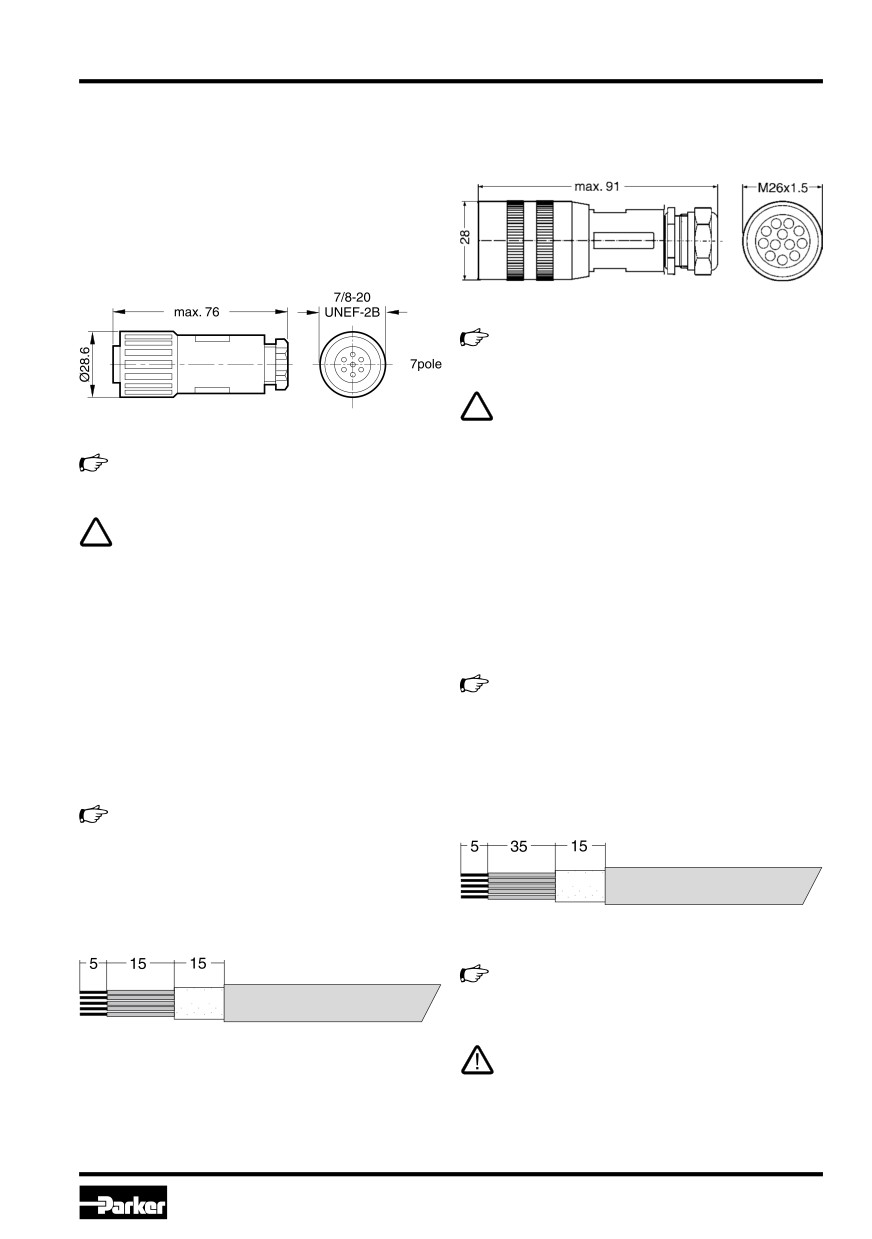
The connection Code W5 requires a 11 + PE fe-
male connector EN 175201-804.
The electrical connection of the valve takes place
by one common cable, which is coupled to the in-
tegrated electronic driver by a central connector
assembly.
The connection Codes F0/S0 requires a 6 + PE fe-
male connector EN 175201-804.
The female connector has to be ordered se-
parately under article nr. 5004711.
A female connector with metal housing is re-
quired! Plastic made models may create func-
tion problems due to insufficient EMC-cha-
The female connector has to be ordered se-
racteristics.
parately under article nr. 5004072.
The connecting cable has to comply to the follow-
ing specification:
A female connector with metal housing is re-
quired! Plastic made models may create func-
Cable type
control cable, flexible,
tion problems due to insufficient EMC-cha-
11 conductors, overall braid
racteristics.
shield
Cross section
min. AWG16/1.0 mm2
The connecting cable has to comply to the follow-
Outer dimension
12...15 mm
ing specification:
Cable length
max. 50 m
Cable type
control cable, flexible,
For cable lengths > 50 m consult factory.
7 conductors, overall braid
shield
The connection cable is coupled to the female con-
Cross section
min. AWG16/1.0 mm2
nector by crimp contacts.
Outer dimension
8...12 mm
Cable length
max. 50 m
Skinning lengths for the connecting cable:
For cable lengths > 50 m consult factory.
The connection cable is coupled to the female con-
nector by solder joints.
Skinning lengths for the connecting cable:
For the workmanlike termination of the crimp
contacts the tool # 932 507-001 - supplier:
Hirschmann - is required.
Do not disconnect cable socket under tensi-
on!
11
Parker Hannifin Corporation
Hydraulics Group
Prop. Directional Control Valve
Operation Manual
Series D*FB / D*1FB
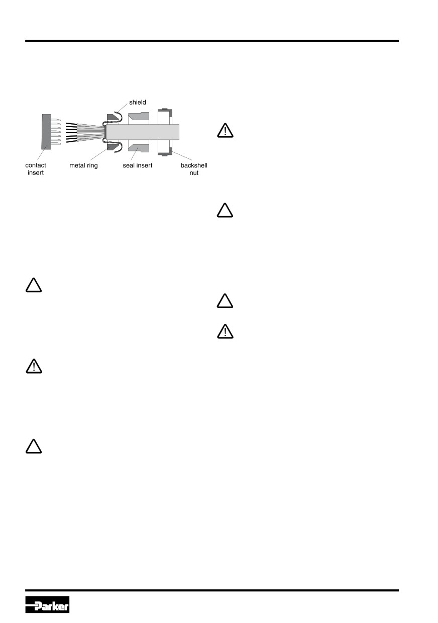
The shielding has to be assembled according the
Electrical Interfacing
outline below:
Supply Voltage:
The supply voltage for the valve has to cover the
range of 18...30 V. The residual ripple may not ex-
ceed 5% eff.
The applied power supply must comply to
the relevant regulations (DIN EN 61558) and
must carry a CE-mark. The operating voltage
for the valve must be free of inductive surges.
Do not exceed the max. value of 30V! Non-
observance of this rule may result in perma-
nent damaging of the valve.
The increased inrush current of the valve
The backshell nut of the cable gland has to be tight-
should be considered when selecting the
en with a suitable tool. The target value for the tight-
power supply. A stabilized power supply with
ening torque is 4 Nm. Tighten the cap nut with a
overcurrent limiting feature should not be
torque of approx. 5 Nm after attaching the female
used. Due to the inrush current of the valve
connector on the socket outlet.
the current limit circuit may respond prema-
turely and create problems during energizing
of the supply voltage.
Incomplete tightening of backshell nut resp.
cap nut may result in automatic release of the
The operation of the valve is blocked if the
connection as well as degradation of the wa-
supply voltage polarity is interchanged.
ter tightness.
Follow the “instructions for use“ for installati-
Each valve requires a separate pre-fuse (ra-
on of female connectors made by other kind
ting: s. techn. data). Non-observance of this
of brands!
instruction may create irreparable damage of
valve resp. incorporated system parts.
The cable connection to the female connec-
tor has to take place by qualified personnel!
A short between individual conductors resp.
to the connector housing, bad soldering as
well as improper shield connection may result
in malfunction and breakdown of the valve.
The mounting surface of the valve has to be
carefully tied to the earth grounded machine
frame. The earth ground wire from the valve
connecting cable as well as the cable shield
have to be tied to the protective earth termi-
nal within the control unit. It is necessary to
use a low ohmic potential connection bet-
ween control unit and machine frame to pre-
vent earth loops (cross section AWG 6).
12
Parker Hannifin Corporation
Hydraulics Group
Prop. Directional Control Valve
Operation Manual
Series D*FB / D*1FB
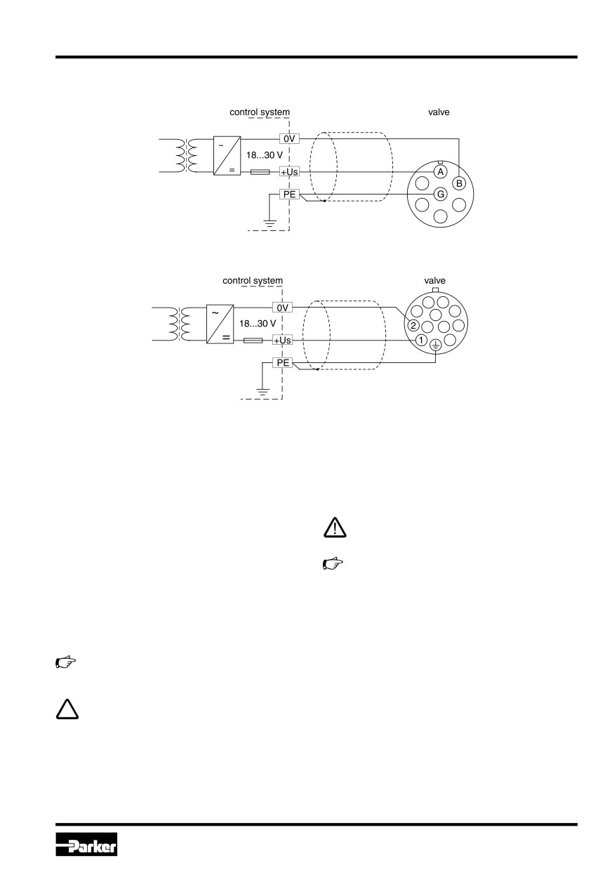
Wiring diagram of supply voltage
Code F0/M0/S0/G0 (6 + PE)
Code W5 (11 + PE)
Command signal input:
The command signal for the valve will be connect-
Incorrect signal amplitude levels may disturb
ed to the difference signal input of the electronic
the functionality and can damage the valve.
driver. The solenoid current behaves proportional to
the command signal amplitude. Different versions of
The option 4...20 mA uses the “0 mA“ condi-
command signal processing are available, depend-
tion as breakdown-information. This means
ing on the valve type. These are described below:
the presence of an evaluable failure informa-
For the function description is assumed as signal
tion if the input signal line is interrupted. In
reference (0V):
this case the actuator drive will be switched
Code F0/M0/S0/G0: pin E, Code W5: pin 5
off. The drive will switch on when the input si-
gnal reaches a value of 3.8 mA, it switches
Details are shown from the technical specifi-
off when the command falls below 3.6 mA.
cations.
This determination follows the NAMUR-spe-
cification NE43.
The command input signal needs to be filte-
NAMUR is an association of users of process
red as well as free of inductive surges and
control technology.
modulations. Due to the sensitivity of the val-
ve a high signal quality is recommended, this
will prevent malfunction.
13
Parker Hannifin Corporation
Hydraulics Group
Prop. Directional Control Valve
Operation Manual
Series D*FB / D*1FB
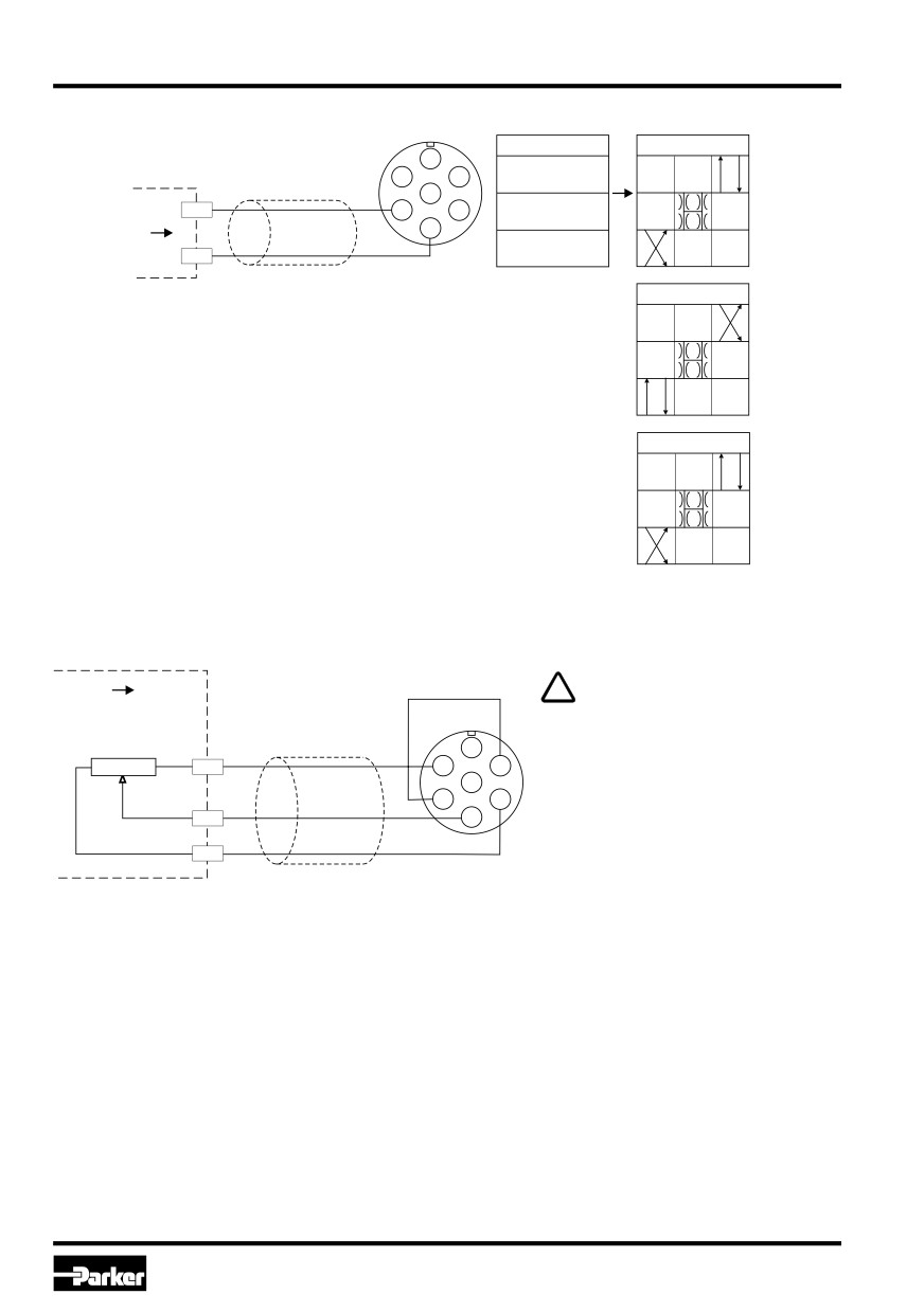
Wiring diagram of voltage command input +10...0...-10 V Code F0/M0 (6 + PE)
valve
command signal
function
A
U D-E
control system
F
B
0...+10 V
U D-E
0V
E
C
D*FB*F0
command
D
0V
signal
U D-E
Uc
0...-10 V
function
D*1FB*F0
function
D*1FB*K0
Wiring diagram of voltage command input +10...0...-10 V via potentiometer Code F0/M0 (6 + PE)
control system
valve
The external potentiometer is fed
via the output “potentiometer sup-
potentiometer
command signal
ply”. To prevent this output from
+10 V
-10 V
A
overload, the resistance value of
5...10 k
-Up
F
B
the potentiometer should be within
a range of 5...10 kOhm. A nomi-
E
C
nal power rating of 0.1 W is suffi-
Uc
D
cient.
+Up
14
Parker Hannifin Corporation
Hydraulics Group
Prop. Directional Control Valve
Operation Manual
Series D*FB / D*1FB
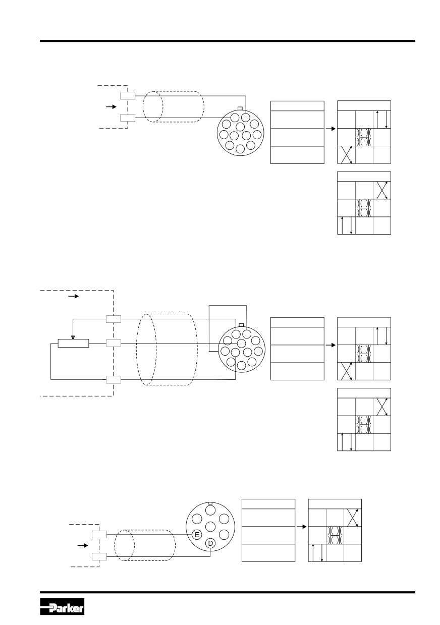
Wiring diagram of voltage command input +10...0...-10 V
Code W5 (11 + PE)
control system
valve
0V
command
command signal
function
signal
I
4-5
Uc
4
5
0...+10 V
I
4-5
D*FB
0V
I
4-5
0...-10 V
function
D*1FB
Wiring diagram of voltage command input +10...0...-10 V via potentiometer
Code W5 (11 + PE)
control system
valve
potentiometer
command signal
Uc
command signal
function
+10 V
-10 V
4
5
U 4-5
0...+10 V
5...10 k
-Up
10
2
9
U 4-5
D*FB
0V
U 4-5
0...-10 V
+Up
function
D*1FB
Wiring diagram of current command input +20...0...-20 mA Code G0 (6+PE)
valve
command signal
function
I D-E
control system
0...+20mA
I D-E
le
D*1FB*G0
command
0mA
signal
I D-E
le
0...-20mA
15
Parker Hannifin Corporation
Hydraulics Group
Prop. Directional Control Valve
Operation Manual
Series D*FB / D*1FB
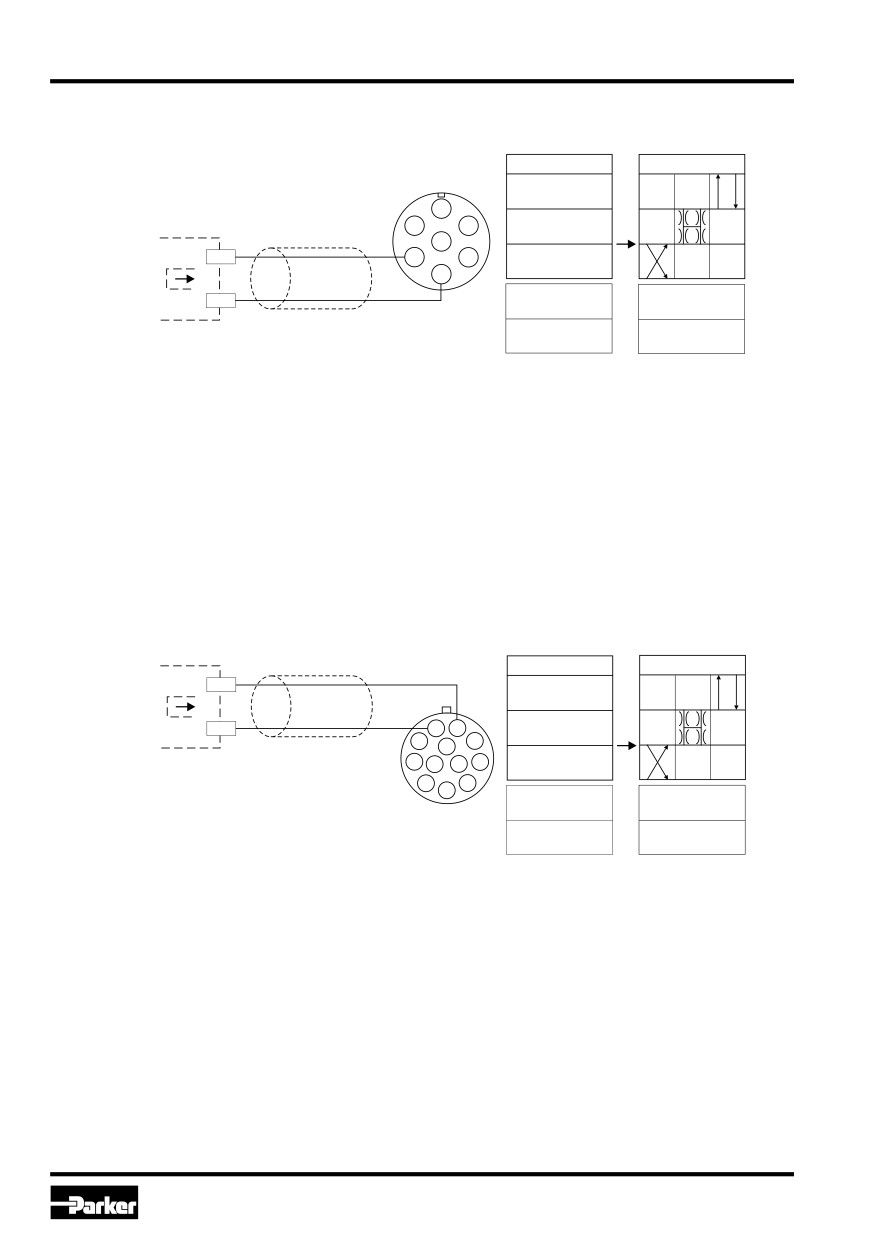
Wiring diagram of current command input 4...12...20 mA
Code S0 (6 + PE)
command signal
function
valve
I D-E
12...20 mA
A
I D-E
control system
F
B
12 mA
Ic
E
C
I D-E
command
4...12 mA
D
signal
I D-E
actuator
Ic
< 3.6 mA
drive off
I D-E
actuator
> 3.8 mA
drive on
Wiring diagram of current command input 4...12...20 mA
Code W5 (11 + PE)
control system
valve
command signal
function
Ic
I
4-5
command
12...20 mA
signal
I
4-5
Ic
4
5
12 mA
I
4-5
4...12 mA
I
4-5
actuator
< 3.6 mA
drive off
I
4-5
actuator
> 3.8 mA
drive on
16
Parker Hannifin Corporation
Hydraulics Group
Prop. Directional Control Valve
Operation Manual
Series D*FB / D*1FB
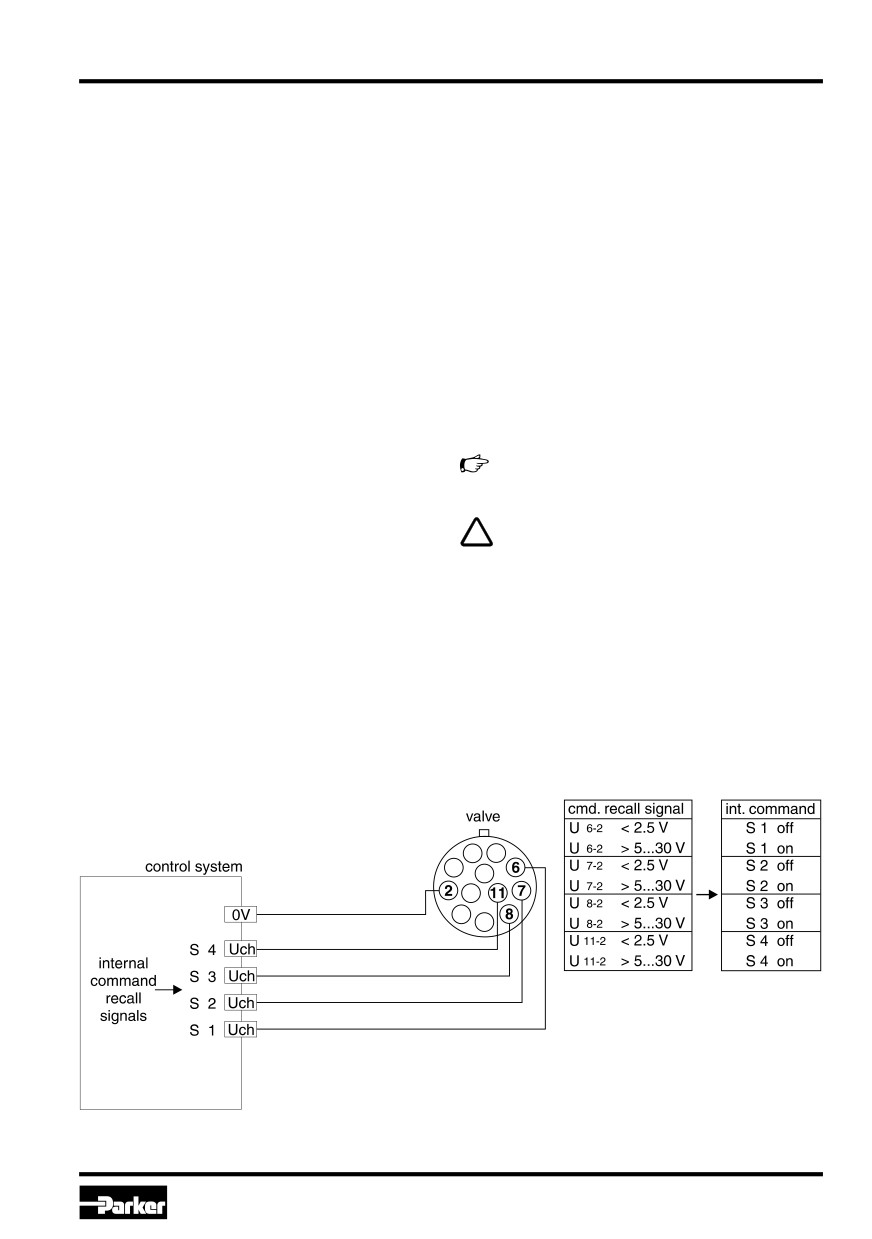
Recall channels for internal command preset
At additive channel recall the internal signal presets
of the recall channels as well as a possible signal
Up to six corresponding inputs are provided for
at the external signal input will be added. The sum
channel recall of internal command presets. The
of the signal values is limited at 100%.
conjunction
options of the internal command channels may be
Example 1: Channel S1 = +50%, channel S2 = +20%,
selectable via the parameter E21. The following op-
external input signal = +5V (= +50%). The
tions are
sum is +120%, in this case +100% input
provided:
signal will be assessed.
• priority dependent
Example 2: Channel S1 = +50%, channel S2 = +20%,
• additive
external input signal = -5V (= -50%). The
sum is +20%, in this case +20% input
At priority dependent channel recall the channel
signal will be assessed.
with the lowest numerical designation has priority
against other
The preset channels are switched through during
simultaneously adressed preset channels.
the signal trigger at the dedicated inputs.
Example: Channels S1, S2, S3 are adressed.
More details are shown from the technical
Channel S1 has priority, the corre-
data.
sponding internal command will be
assessed as input signal.
The channel recall signals needs to be filte-
red as well as free of inductive surges and
The preset channels have priority against the an-
modulations. To prevent malfunctions a high
alog signal input for the external command.
signal quality is recommended.
Wiring diagram of recall channels
Code W5 (11 + PE)
17
Parker Hannifin Corporation
Hydraulics Group
Prop. Directional Control Valve
Operation Manual
Series D*FB / D*1FB
5. Operating Instructions
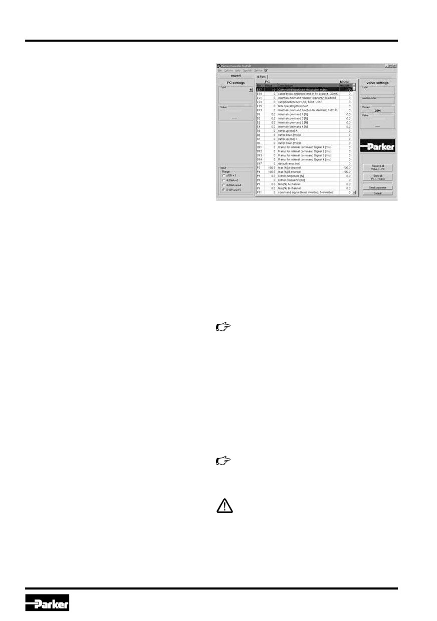
ProPXD screenshot
Basically the valve performs the task of converting
a command signal into a proportional spool stroke
with the highest possible dynamic. For these pur-
poses the input value will be electronically pro-
cessed and provides via a power amplifier stage
the required current for the valve solenoid.
ProPxD parameterizing software:
The ProPxD software permits comfortable parame-
ter setting for the module electronic. Via the clearly
arranged entry mask the parameters can be noticed
and modified. Storage of complete parameter sets
to floppy or hard disk is possible as well as printout
or record as a text file for further documentation.
Stored parameter sets may be loaded anytime and
transmitted to other valves. Inside the electronic a
Hardware requirements
nonvolatile memory stores the data with the option
• PC with operating system from Windows® 95
for recalling or modification.
upwards
Features
• Interface RS232
• comfortable editing of all parameters
• display resolution min. 800 x 600
• depiction and documentation of parameter sets
• connection cable between PC and electronic
module
• storage and loading of optimized parameter
adjustments
• storage requirement approx. 4 MB
• executable with all actual Windows® operating
It is recommended to select “small fonts” at
systems from Windows® 95 upwards
the display setting, otherwise distortion of the
• plain communication between PC and electron-
display may occur.
ic via serial interface RS232.
Cable Specification
Comfortable interface, see Parker freeware avail-
The connection of the valve electronic to a PC re-
able from infohcd@parker.com.
quires a special cable. It may be ordered under code
40982923. The cable has to be inserted between
an unused serial port COM1 or COM2 of the PC
and the 5pole socket connector of the valve elec-
tronic (parametrizing connector).
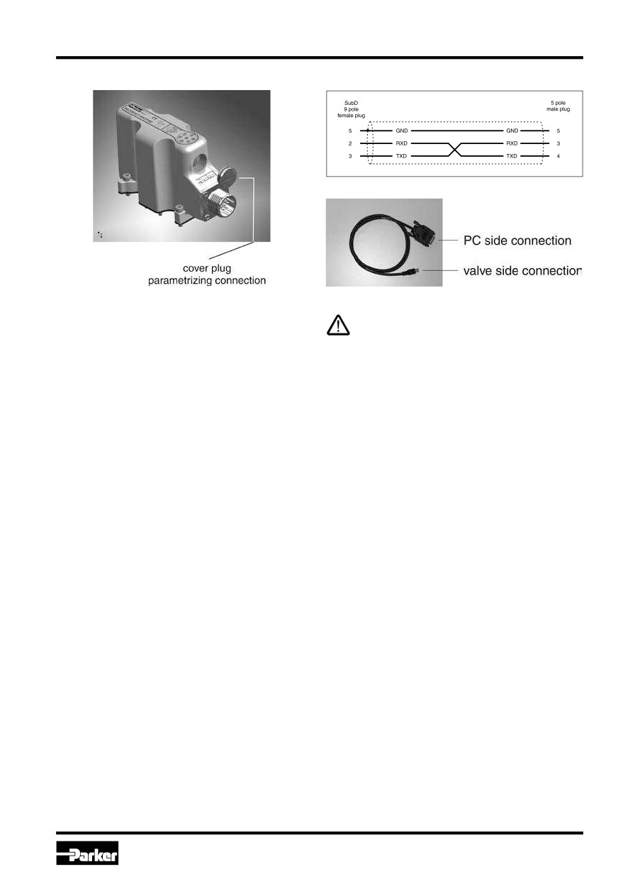
Before connecting of the parametrizing ca-
ble a cover plug has to be removed from the
electronic housing.
Attention! The valve electronic provides no
USB interface, but can only be parametrized
via an RS232 - connection. Therefore the usa-
ge of USB standard cables is permitted and
may result in damaging of valve resp. PC.
18
Parker Hannifin Corporation
Hydraulics Group
Prop. Directional Control Valve
Operation Manual
Series D*FB / D*1FB
Parametrizing connection
Parametrizing cable 40982923
The cover plug has to be re-installed after
completion of the parametrizing work.
Program installation
Software Operating
Please check before installation if the above hard-
Brief instruction for first startup:
ware requirements are met. If your PC has already
• Connect the valve electronic to the supply voltage.
stored an older version of the “ProPxD” program, it
• Connect the valve electronic to a PC via the pa-
has to be deinstalled by using the Windows® - sys-
rametrizing cable.
tem control feature.
• Click on the ProPxD icon to start the operat-
Program installation sequence:
ing program.
• terminate the execution of other programs
• After displaying the program resp. data base ver-
• insert ProPxD-software CD
sion a program window opens and the connect-
• execute the file “setup.exe”
ed valve will be automatically identified (possibly
a manual identification via the button “Receive
• follow the instructions on the screen
all” is necessary).
Answer the question, if an older version should be
• Select the desired version via the menu “Op-
overwritten, with “ok”. During the installation you
tions/Optionen” with the menu item “Language/
may change destination drive resp. installation
path, if needed (i.e. if the storage space on drive
Sprache”.
“c” is not sufficient).
• The valve specific default parameters are already
Please answer also “ok” if at the end of the instal-
available within the parameter table.
lation the program reports any system information.
• Individual parameters may be selected via
After successful installation the desktop display
mouse or the arrow buttons at the center of the
shows the ProPxD icon for starting the program.
program screen.
19
Parker Hannifin Corporation
Hydraulics Group
Prop. Directional Control Valve
Operation Manual
Series D*FB / D*1FB
• Parameter changes are possible via mouse or
A horizontal bar graph readout between
the arrow buttons on the bottom left within the
the communication buttons shows the data
program screen, also the parameter values may
transfer state.
be edited via the keyboard.
Because the ProPxD program has also offline
• Modified parameters will be stored via the “En-
ter” key or via the button “Update list”.
(i.e. without connection to the valve) function-
ality, a manual pre-selection of the parameters
• After completing of all modifications, the entire
is possible. After selection of the valve type
parameter set may be transmitted to the valve
via the menu “Options” the parameters may
via the button “send all”, also the parameters
be set and stored for later transmission.
will be nonvolatile stored.
Note the design series while selection of the
• The chosen parameters may be optionally stored
valve!
on the PC via the “File”-menu with the menu item
“Save as”, data retrieving is always possible via
The “File” menu provides the functions “Printer
the function “Load out of database”
setup”, “Print preview” and “Print”. The print pre-
view includes the option for parameter set storage
Extended functions:
as text file (format .txt) prior to further processing.
The user software is shared into 2 parameter
The “Options” menu provides also the selection of
ranges:
the RS232 interface port via the menu item “Port”.
Via the menu item “Load out of database” previ-
• basic mode
ously stored parameter sets may be loaded.
• expert mode
Adjustment parameters
For normal startup the basic mode is absolutely suf-
The available parameters may be divided into
ficient. It permits the setting of all application spe-
multiple groups and are characterized by different
cific parameters to match the valve function with
letters:
the task setting.
S-parameters
In case of special applications the valve parame-
P-parameters
ters may be adapted via the expert mode.
E-parameters
The operating mode may be selected from the “Op-
tions”- menu and remains after terminating and re-
start of the program.
Changing of expert parameters is only permit-
ted for qualified personnel. Incorrect settings
may lead to malfunction! In case of parameter
changes shut the drive down!
To prevent an unauthorized access for the ex-
pert mode, a pass word is requested. The name is
“parker” and cannot be changed. Thus additional-
ly to the button “Default” for loading of the default
parameters, the button “Send parameter” appears
in the “Expert”-operating mode. This button trans-
mits only the setting of one single parameter to the
connected valve. Thus a quick tuning of single pa-
rameters is permitted during the setup.
20
Parker Hannifin Corporation
Hydraulics Group
Prop. Directional Control Valve
Operation Manual
Series D*FB / D*1FB
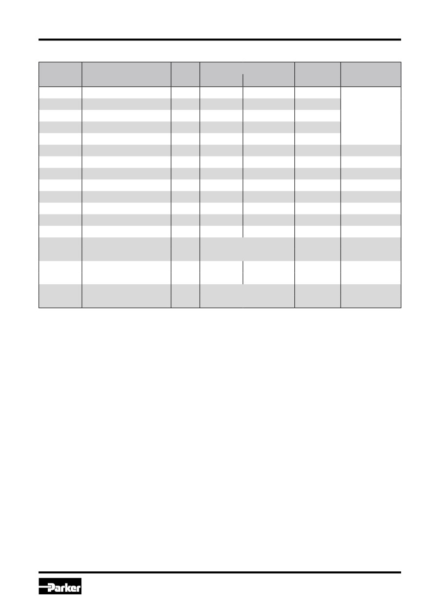
Parameter overview for basic mode
Parameter Range
Default
Parameter
Description
Unit
Comment
from
up to
Setting
S1
internal Sollwert S1
%
-100
100
0.0
S2
internal Sollwert S2
%
-100
100
0.0
code W5 only
S3
internal Sollwert S3
%
-100
100
0.0
S4
internal Sollwert S4
%
-100
100
0.0
S5
ramp accel. channel A
ms
0
32500
0
S6
ramp decel. channel A
ms
0
32500
0
S7
ramp accel. channel B
ms
0
32500
0
S8
ramp decel. channel B
ms
0
32500
0
P3
MAX channel A
%
50.0
100.0
100.0
P4
MAX channel B
%
50.0
100.0
100.0
P7
MIN channel A
%
0.0
50.0
0.0
P8
MIN channel B
%
0.0
50.0
0.0
P11
polarity command
-
0
1
0
1 = ±10V
E17
option command
-
1 = ±10V
code W5 only
3 = 4-20mA
cable break detection
0 = ±10V
codes S0 & W5
E19
-
0
0 = +/-10V
command
1 = 4-20mA
only
0 = 1%
E25
MIN operating threshold
-
0 = 1%
1 = 0.01%
21
Parker Hannifin Corporation
Hydraulics Group
Prop. Directional Control Valve
Operation Manual
Series D*FB / D*1FB
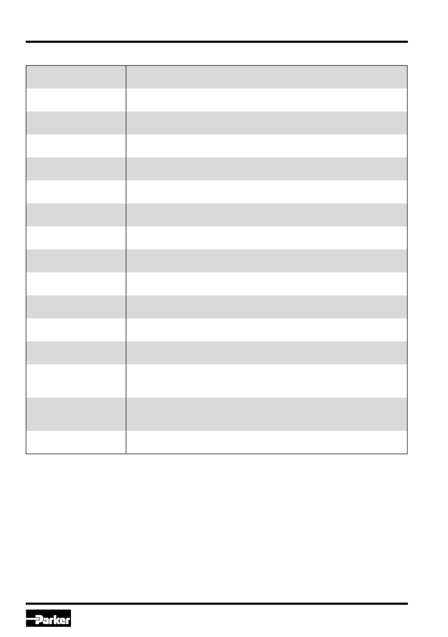
Individual Description of Basic Parameters
S1
Adjustment of the internal command signal channel S1.
command signal S1
To attenuate of an external accessible command signal.
S2
Adjustment of the internal command signal channel S2.
command signal S2
To attenuate of an external accessible command signal.
S3
Adjustment of the internal command signal channel S3.
command signal S3
To attenuate of an external accessible command signal.
S4
Adjustment of the internal command signal channel S4.
command signal S4
To attenuate of an external accessible command signal.
S5
Adjustment of ramp rate for increasing of the positive signal polarity.
ramp accel. channel A
To avoid switching noise.
S6
Adjustment of ramp rate for decreasing of the positive signal polarity.
ramp decel. channel A
To avoid switching noise.
S7
Adjustment of ramp rate for increasing of the negative signal polarity.
ramp accel. channel B
To avoid switching noise.
S8
Adjustment of ramp rate for decreasing of the negative signal polarity.
ramp decel. channel B
To avoid switching noise.
P3
Adjustment of maximum signal span for positive output signal.
MAX +
To match the command signal span to the valve operating range.
P4
Adjustment of maximum signal span for negative output signal.
MAX -
To match the command signal span to the valve operating range.
P7
Adjustment for positive output signal step at 0,1% command signal.
MIN +
To compensate for the overlap of the valve spool.
P8
Adjustment for negative output signal step at 0,1% command signal.
MIN -
To compensate for the overlap of the valve spool.
P11
Adjustment of the command signal polarity.
command signal polarity
To match the command signal polarity to the valve operating direction.
E17
Adjustment of the command signal option.
type of command signal
To match the command signal input to the input signal mode.
device
E19
Adjustment of the operating mode for the command cable break
cable break detection
detection. To turn on resp. off of the cable break detection of the
command
command signal at a selected command signal option of 4...20 mA.
E25
Adjustment of the MIN operating threshold.
MIN operating threshold
To match the response sensitivity for the MIN-stroke step.
22
Parker Hannifin Corporation
Hydraulics Group
Prop. Directional Control Valve
Operation Manual
Series D*FB / D*1FB
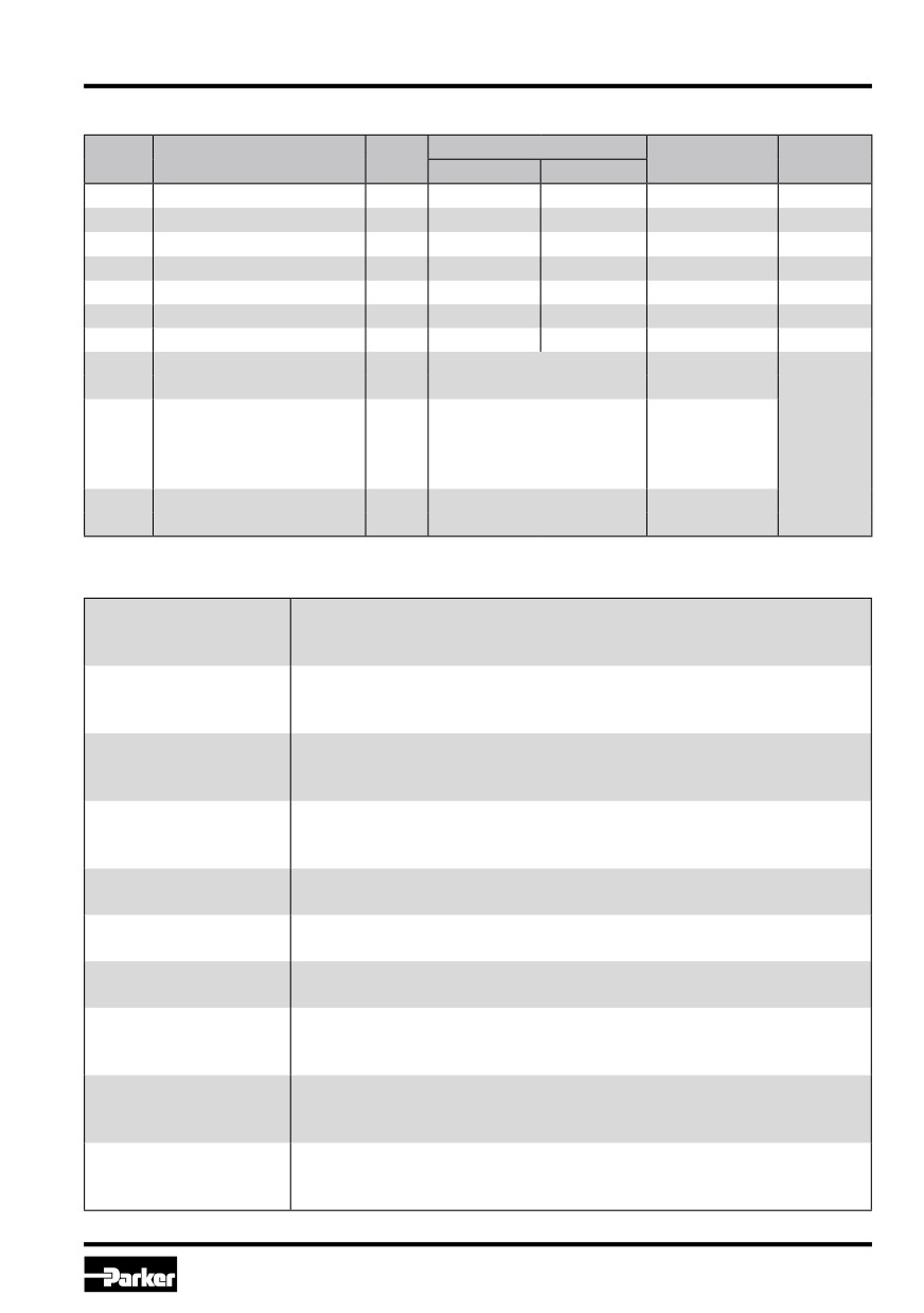
Parameter overview for expert mode
Para-
Parameter Range
Description
Unit
Default Setting
Comment
meter
from
up to
S11
ramp for int. command S1
ms
0
32500
0
S12
ramp for int. command S2
ms
0
32500
0
S13
ramp for int. command S3
ms
0
32500
0
S14
ramp for int. command S4
ms
0
32500
0
S17
default ramp
ms
0
32500
0
P5
dither amplitude
%
0
10.0
0
P6
dither frequency
Hz
0
300
0
option internal command
0 = priority dependent
0 = priority
E21
-
signal conjunction
1 = additive
dependent
0 = quadrant dependent
int. command signal
(S5...8)
0 = quadrant
Code W5
E22
-
ramp function
1 = int.
command depend.
dependent
only
(S11...14)
int. command signal
0 = standard
E83
-
0 = standard
functionality
1 = special option DFL
Individual Description of Expert Parameters
S11
Adjustment of the ramp rate for the internal command signal channel S1.
ramp for internal
To avoid switching noise.
command signal 1
S12
Adjustment of the ramp rate for the internal command signal channel S2.
ramp for internal
To avoid switching noise.
command signal 2
S13
Adjustment of the ramp rate for the internal command signal channel S3.
ramp for internal
To avoid switching noise.
command signal 3
S14
Adjustment of the ramp rate for the internal command signal channel S4.
ramp for internal
To avoid switching noise.
command signal 4
S17
Adjustment of the ramp rate for the default ramp.
default ramp
To avoid switching noise.
P5
Adjustment of dither amplitude.
dither amplitude
To reduce the influence of solenoid friction.
P6
Adjustment of dither frequency.
dither frequency
To match the dither signal to the valve dynamic.
E21
Adjustment of the conjunction for the internal command signals.
internal command signal
To match the command signal logic.
conjunction
E22
Adjustment of the ramp function for the internal command signals.
internal command signal
To match the ramp functionality.
ramp function
E83
Adjustment of the functionality for the internal command signals.
internal command signal
To match for the special option DFL.
functionality
23
Parker Hannifin Corporation
Hydraulics Group
Prop. Directional Control Valve
Operation Manual
Series D*FB / D*1FB
Error messages
Malfunctions when using the ProPxD software
program will be indicated via appropriate failure
messages.
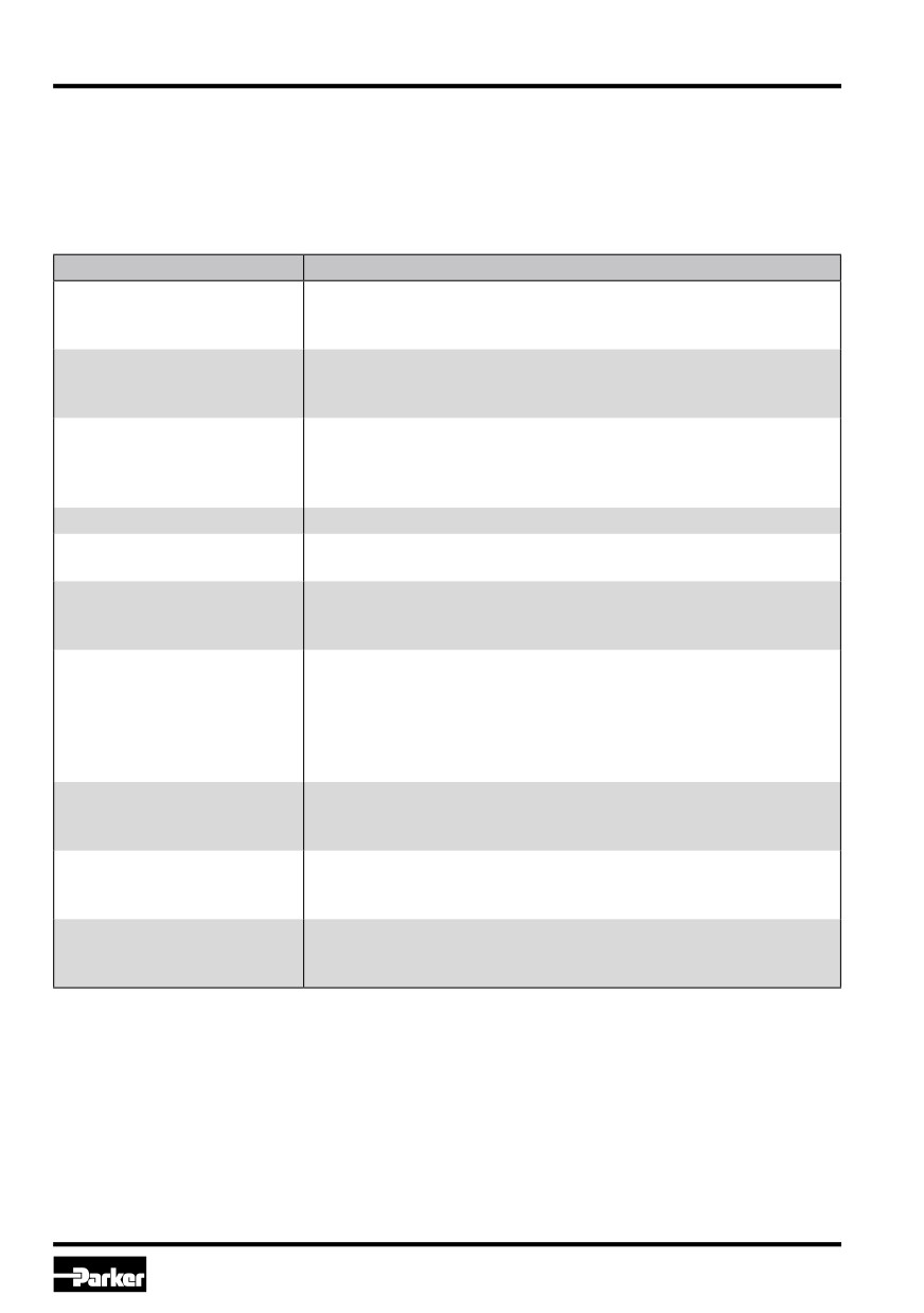
Failure messages and corrective actions:
Failure message
Description/corrective action
The Com Port is not available!
Terminate the other program, or quit the message and select an-
other RS-232 port via the menu “Options > Port”. Afterwards recon-
nect the parametrizing cable.
Unable to open COM port
Com port is not available. Quit the message and select another
RS-232 port via the menu “Options > Port”. Afterwards reconnect
the parametrizing cable.
There is no module/valve con-
No data exchange possible. Either the electronic has been re-
nected or the communication
moved, the port is mismatched, or the connection will be disturbed
is disturbed! Please check
by strong electrical fields. Check if the Com port is set for “9600, 8,
also the interface!
1. none, none” via the menu “Options > Port”.
Wrong password
Retype the password, notice the exact spelling (case sensitivity).
Wrong input
An unvalid character or a value outside the permitted range has
been used at parameter entry.
Keep the entered para-
During parameter loading from the electronics memory the preset
meters?
parameters from the left hand screen display may be rejected or
maintained.
The chosen module/valve
In principle, parameters dedicated to a type which deviates from
isn´t the same as the con-
the connected valve may be edited. However, for data transmitting
nected hardware. Attention!
the correct valve has to be connected. If parameters will be loaded
Unsaved parameters will be
from a valve which deviates from the selected one, the param-
lost.
eters from the left hand side screen display of the program will be
overwritten.
The chosen hardware isn´t
The wrong valve type has been selected from the database, after-
the same as the connected
wards the function “send all” has been executed.
module/valve.
Attention! Factory settings
Default parameters has been read out from the database instead
will be changed! Transmit
from the valve via the function “receive all”.
anyhow?
file name.pxd already exists.
The file name already exists within the indicated directory. Select
Do you want to replace the
another name, another directory or overwrite the existing file with
file?
“OK”.
24
Parker Hannifin Corporation
Hydraulics Group
Prop. Directional Control Valve
Operation Manual
Series D*FB / D*1FB
Air Bleeding of Hydraulic System
6. Maintenance
During initial startup, after an oil change as well
Service work may only be carried out by quali-
as after the opening of lines or valves the hydrau-
fied personnel. Detailed knowledge of the ma-
lic system must be air bleeded. Air in the hydraulic
chine functions concerning switching on and
system is very disadvantageous and therefore un-
off as well as of the required safety relevant
desirable for the control system. The pipeline net-
technical tasks is required!
work is vented at its highest point. The fitting may
be loosened a little so that the air can escape with
Periodical maintenance is essential for the longevity
only a small amount of oil loss. When the oil is no
of the system and guarantees reliability and avail-
longer foaming, the fitting is re-tightened. Afterwards
ability. The following properties of the system has
all functions are run through, one after the other, in
to be checked in continuous short time intervals:
no-load operation with low pressure and with full
• oil level in the tank
cylinder stroke. Afterwards the system should be
vented once more.
• max. working temperature
• condition of the pressure fluid (visual inspection,
After air bleeding the oil level in the tank must
colour and smell of hydraulic fluid)
be checked, and refilled as necessary!
• working pressure levels
Filter
• gas pre-load pressure on the pressure accumu-
lator
The function and lifetime of the valve are strongly
affected by the cleanliness of the fluid.
• leakage on all system components
Dirt is the greatest enemy of the hydraulic
• condition of filter elements
system!
• condition of hose lines
• cleanliness of components
There are three important sources of dirt to watch
for:
After a certain operating duration a change of the
• contamination arising during installation
hydraulic fluid is required. The frequency of change
• contamination arising during operation, friction
depends from the following circumstances:
wear
• kind resp. grade of the pressure fluid
• impurities from the environment
• filtering
Basically a purity level class of 7 acc. NAS 1638
• operating temperature and environmental con-
is required.
ditions
Pay attention to maintenance details!
Flushing
It is recommended to flush the long pipelines by
short circuiting the pressure and return lines, es-
pecially for large, central pressure oil stations. This
prevents the installation dirt from entering the valve.
25
Parker Hannifin Corporation
Hydraulics Group
Prop. Directional Control Valve
Operation Manual
Series D*FB / D*1FB
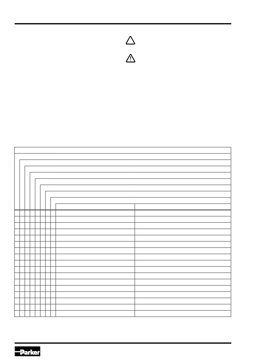
7. Trouble Shooting
Basis of troubleshooting is always a systematic
For suspect of a sluggish spool the valve may
approach. At first the following questions have to
be flushed with clean pressure fluid.
be checked:
Troubleshooting in a hydraulic system requires
• Are there practical experiences with similar
in either case a systematic approach. The
failures?
work may exclusively be performed by quali-
• Have system adjustments been changed?
fied personnel, as it requires detailed know-
ledge about function and construction of the
Afterwards starting of troubleshooting by means of
system. Reversals or dissassemblings may
a priority list of the most likely reasons.
not be taken imprudently! Prior to the works
it has to be clarified, if the system has been
operated properly until the failure occured.
malfunction at hydraulic load runtime
- generally no function
- high frequent oscillation
- low frequent oscillation
- one way operation only
- speed variations at unchanging command
- different speeds depending on travel direction
- speed too low
- drifting without command
possible reasons for malfunction
corrective actions
x
hydraulic pump resp. motor defective
replace hydraulic pump resp. motor
x
x
x
x
x
x
drive overloaded
reduce pressure resp. speed, increase valve size
x
x
x
x
x
x
x
valve contaminated
clean pressure fluid, filter / flush valve
x
x
hydraulic fluid too viscous / too cold
change fluid grade, provide operational temperature
x
x
x
too low oil level within tank
refill pressure fluid
x
x
x
filter contaminated
clean resp. replace filter
x
x
x
x
supply voltage too low
keep supply voltage range
x
supply voltage carries too much ripple
reduce ripple
x
x
x
command signal too low
increase command signal
x
command signal carries too much ripple
reduce ripple
x
dither signal amplitude too high
reduce parameter P5
x
dither signal amplitude too low
increase parameter P5
x
x
x
x
x
central connector contact failure
clean contacts resp. replace connector
x
feed cable interrupted
fix feed cable
x
x
x
x
x
x
x
wiring sequence incorrect
correct wiring sequence
x
x
feed cable without shielding
change cable grade
x
*)
pilot flow configuration incorrect
correct pilot flow configuration
*) only for D*1FB
26
Parker Hannifin Corporation
Hydraulics Group
Prop. Directional Control Valve
Operation Manual
Series D*FB / D*1FB
8. Accessories / Spare Parts
Accessories
The following accessories are available for the
valves series D*FB/D*1FT:
D1FB:
D111FB:
bolt kit
ordering code BK375
bolt kit
ordering code BK386
Code F0/M0/S0/G0:
Code F0/M0/S0/G0:
female connector 6+PE ordering code 5004072
female connector 6+PE ordering code 5004072
Code W5:
Code W5:
female connector 11+PE ordering code 5004711
female connector 11+PE ordering code 5004711
D3FB:
bolt kit
ordering code BK385
Spare Parts
Code F0/M0/S0/G0:
female connector 6+PE ordering code 5004072
The following spare parts are available:
Code W5:
D1FB:
female connector 11+PE ordering code 5004711
seal kit NBR
ordering code SK-D1FB-N
D31FB:
D3FB:
bolt kit
ordering code BK385
seal kit NBR
ordering code SK-D3FB-N
Code F0/M0/S0/G0:
D31FB:
female connector 6+PE ordering code 5004072
seal kit NBR
ordering code SK-D31FTN
Code W5:
female connector 11+PE ordering code 5004711
D41FB:
seal kit NBR
ordering code SK-D41FTN
D41FB:
bolt kit
ordering code BK320
D91FB:
Code F0/M0/S0/G0:
seal kit NBR
ordering code SK-D91FTN
female connector 6+PE ordering code 5004072
D111FB:
Code W5:
seal kit NBR
ordering code SK-D111FTN
female connector 11+PE ordering code 5004711
D91FB:
bolt kit
ordering code BK360
Code F0/M0/S0/G0:
female connector 6+PE ordering code 5004072
Code W5:
female connector 11+PE ordering code 5004711
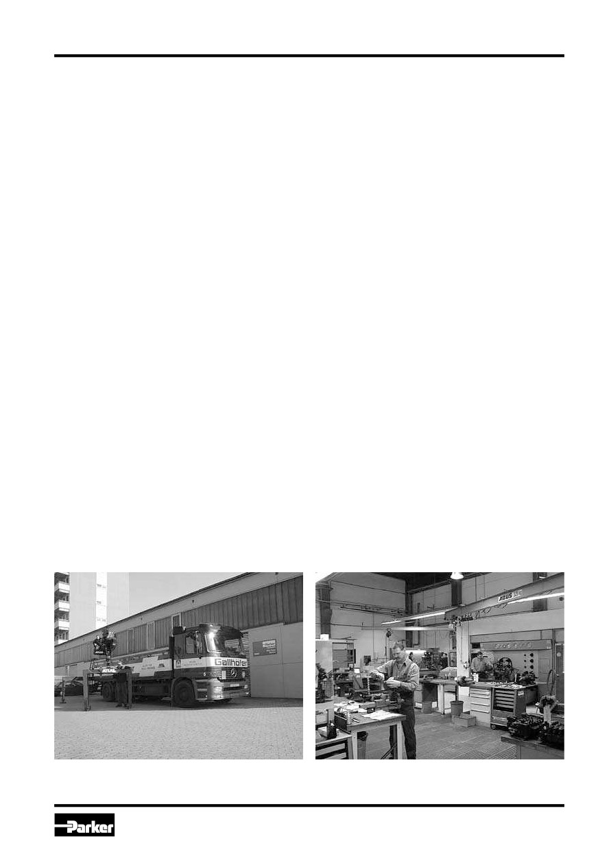
Kaarst, Germany: Parker Hannifin GmbH
Kaarst, Germany: Parker Hannifin GmbH
27
Parker Hannifin Corporation
Hydraulics Group