FAAC Прямонаправленные фотоэлементы
E
UNI EN ISO 9001-085
PHOTOBEAM
I La fotocellula direzionale con allineamento Photobeam, composta da un Trasmettitore ed un
Ricevitore a raggi infrarossi modulati, è un dispositivo di sicurezza. L’oscuramento del fascio luminoso,
provoca il cambiamento di stato del contatto elettrico sul Ricevitore.
Alimentazione
24VDC(19÷35 VDC) / 24VAC(21,5÷25,5 VAC)
Tipo contatti
NO/NC
Assorbimento
Tx= 20mA Rx= 30mA
Portata max. contatti
100mA/24VDC
Portata max.
30m
Angolo di rilevazione
+/- 4°
IP
54
Temperatura ambiente
-20°C / +55°C
Tempo rilevamento ostacolo
10mSec
Installazione
a parete / su colonnetta
GB Photobeam is a directional photocell with alignment facility consisting of a modular infrared
Transmitter and Receiver. It is classed as a safety device. Breaking the luminous beam causes the state
of the electric contact on the Receiver to be switched.
Power supply
24VDC(19÷35 VDC) / 24VAC(21,5÷25,5 VAC)
Type of contacts
NO/NC
Input
Tx= 20mA Rx= 30mA
Contact rating
100mA/24VDC
Max. range
30m
Detection angle
+/- 4°
IP
54
Ambient temperature
-20°C / +55°C
Beam response time
10mSec
Installation
wall / stand
RU Прямонаправленные фотоэлементы требующие центровки, в комплект входит инфракрасный
передаьчик и приёмник. Являются классическим устройством безопасности, при прерывание луча
изменяется статус приёмника путём переключения реле
П итание
24В пост(19÷35В )
/
24В пер(21,5÷25,5В )
Тип контактов
Н О /Н З
П отребл ение
Tx=
20мA Rx=
30мA
Н агрузка на контакты
100 м A /2 4 В
М аксим альная дальность
30 м
Угол рассеивания
+/- 4°
IP
54
Р абочая тем пература
-20°C / +55°C
В рем я срабаты вания
10 м се к
Установка
стена
/ стойка
D
Bei der ausrichtbaren Lichtschranke Photobeam, die aus einem Empfänger und einem Sender für
moduliertes Infrarotlicht besteht, handelt es sich um eine Sicherheitsvorrichtung. Die Unterbrechung
des Lichtstrahls bewirkt die Änderung des Zustands des elektrischen Kontakts des Empfängers.
Stromversorgung
24VDC(19÷35 VDC) / 24VAC(21,5÷25,5 VAC)
Kontakttyp
SCHLIESSER/ÖFFNER
Stromaufnahme
Tx= 20mA Rx= 30mA
Bemessungsstrom der Kontakte
100mA/24VDC
Max. Reichweite
30m
Erfassungswinkel
+/- 4°
IP
54
Umgebungstemperatur
-20°C / +55°C
Ansprechzeit
10mSec
Installation
Wand / Säule
E La fotocélula direccional con alineamiento Photobeam, está formada por un Transmisor y un
Receptor de rayos infrarrojos modulados, y un mecanismo de seguridad. El oscurecimiento del haz
luminoso provoca el cambio de estado del contacto eléctrico en el Receptor.
Alimentación
24VDC(19÷35 VDC) / 24VAC(21,5÷25,5 VAC)
Tipo contactos
NO/NC
Absorción
Tx= 20mA Rx= 30mA
Alcance máx. contactos
100mA/24VDC
Alcance máx.
30m
Angulo de detección
+/- 4°
IP
54
Temperatura ambiente
-20°C / +55°C
Tiempo detección del obstáculo
10mSeg
Instalación
en pared / en columna
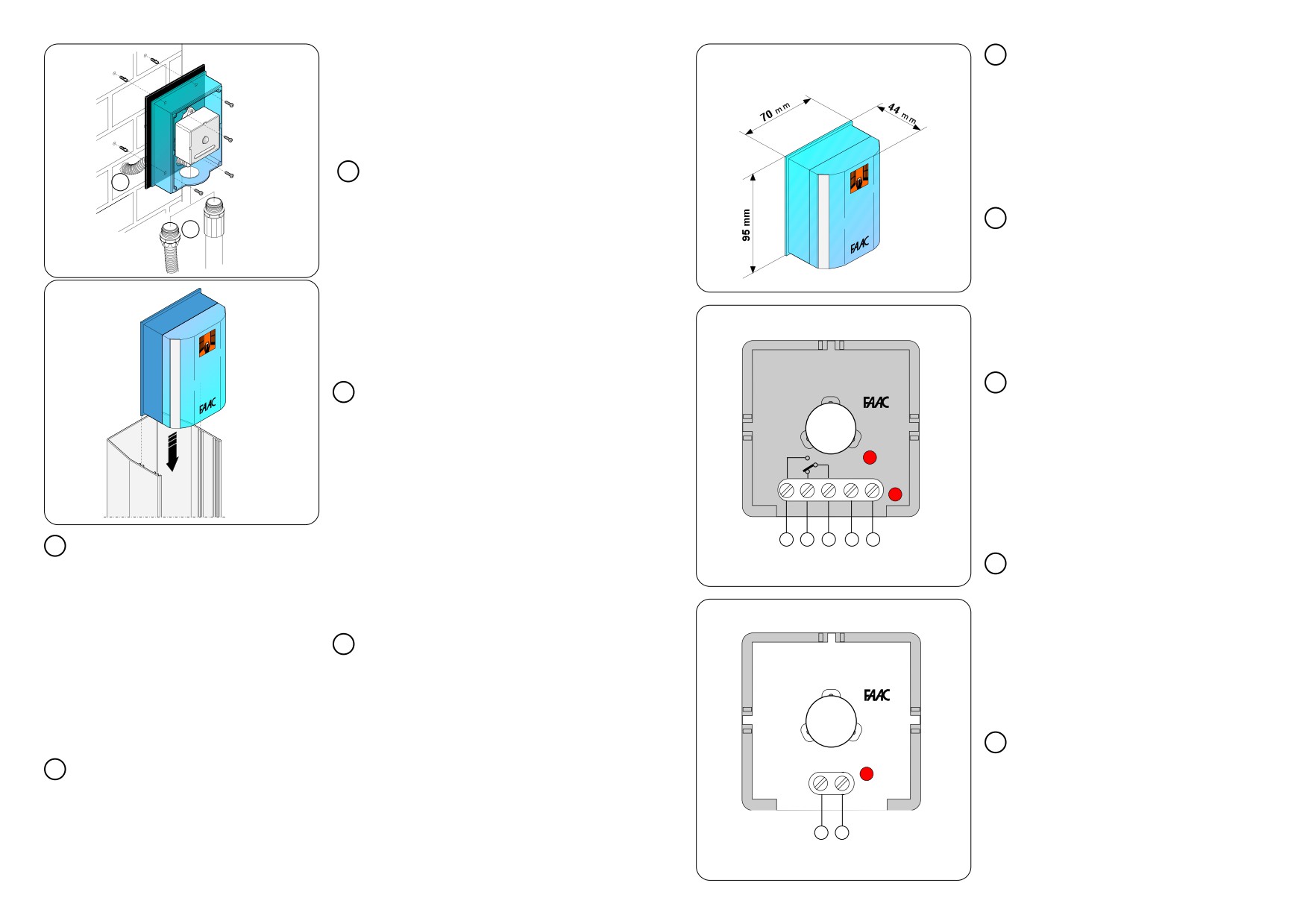
- Wall with embedded tube (fig.1- item A) or with
DIMENSIONI - DIMENSIONS - РАЗМЕРЫ -
I
2. COLLEGAMENTI ELETTRICI
outer tube/sheath (fig.1- item B).
ABMESSUNGEN - MEDIDAS
•Eseguire i collegamenti elettrici sulle morsettiere
- On special stand (fig.2).
del Ricevitore (fig.4) e del Trasmettitore (fig.5).
•Carry out the work necessary for the electrical
•Eseguire i cablaggi elettrici all’apparecchiatura
connections.
elettronica di comando e ad altre eventuali
•In the case of wall installation, fix the Photobeam
fotocellule presenti nell’impianto.
enclosures and respective gaskets using suitable
ÜFare riferimento agli schemi riportati nelle
screws and screw anchors.
istruzioni delle apparecchiature per le diverse
RU 1. УСТАНОВКА
configurazioni.
A
•Procedere all’allineamento .
ÜДля максимально эффективной работы
расположите датчики строго друг напротив друга.
ÜЕсли используются 2 пары фотоэлементов,
GB
2. ELECTRICAL CONNECTIONS
B
расположите приёмники на противоположных
•Effect the necessary electrical connections to the
сторонах
terminal blocks of the Receiver (fig.4) and
A
Возможны 2 типа установки :
Transmitter (fig.5).
- на стене с внутренним подводом кабеля (рис.1-А)
C
•Connect wiring to the electronic control unit and
или с внешним подводом (рис.1- B).
any other photocells present in the system.
- на специальную стойку (рис.2).
ÜRefer to the diagrams contained in the electronic
•выполните необходимые электрические
control unit instructions for details of the various
подключения
RX
configurations.
•при креплении на стене, закрепите корпуса с
•Proceed with alignment.
помощью винтов
RU
2. ЭЛЕКТРИЧЕСКИЕ ПОДКЛЮЧЕНИЯ
D
1. MONTAGE
ÜZur Gewährleistung des optimalen Betriebs
•Выполните электрические подключения приёмника
Empfänger und Sender gefluchtet anordnen.
(рис.4) и передатчика (рис.5).
ÜBei Montage von zwei Lichtschranken zur
•Подключите фотоэлементы к блоку
Vermeidung einer gegenseitigen Beeinflussung die
управления, при наличии нескольких пар
DL2
Sender auf gegenüberliegenden Seiten anordnen.
фотоэлементов, подключите все
Es sind zwei Arten von Installation möglich:
DL1
ÜДля корректного подключения к блоку
-Wandmontage mit unter Putz verlegtem
управления, прочтите инструкцию на данный блок.
B
Installationsrohr (Abb. 1- Pos. A) oder mit Installa-
tionsrohr/Kabelmantel auf Putz (Abb. 1-Pos. B).
•Выполните центровку
-auf entsprechender Säule (Abb. 2)
1
2
3
4
5
I
1.
MONTAGGIO
•Die Vorbereitungen für den elektrischen Anschluß
НО НЗ COM
-
+
ÜPer un funzionamento ottimale, collocare il
treffen.
D
D
2. ELEKTRISCHE ANSCHLÜSSE
Ricevitore e il Trasmettitore allineati.
•Für die Wandmontage die Behälter der
•Die elektrischen Anschlüsse an die Klemmen des
ÜNel caso siano previste due coppie di fotocellule,
Photobeam einschließlich der zugehörigen
Empfängers (Abb. 4) und des Senders (Abb. 5)
per evitare interferenze reciproche, disporre i
Dichtungen mit Hilfe geeigneter Schrauben und
ausführen.
Ricevitori su lati opposti.
Dübel befestigen.
TX
•Die Verdrahtung mit dem elektronischen
Sono possibili due installazioni:
Steuergerät und den ggf. installierten weiteren
- A parete con tubo ad incasso (fig.1- rif. A) o con
E
1. MONTAJE
Lichtschranken der Anlage vornehmen.
tubo/guaina esterni (fig.1- rif.B)
Ü Para un óptimo funcionamiento, colocar el
ÜFür die verschiedenen Konfigurationen die Pläne
- Su apposita colonnetta (fig.2)
Receptor y el Transmisor en línea.
in den Betriebsanleitungen der Geräte zu Rate
•Eseguire le predisposizioni per i collegamenti
ÜEn el caso en que estén previstas dos parejas
ziehen.
elettrici.
de fotocélulas, para evitar interferencias
•Die Fluchtung vornehmen.
•Nel caso di installazione a parete, fissare i
recíprocas, colocar los Receptores en lados
contenitori Photobeam con la relativa guarnizione
opuestos.
utilizzando viti e tasselli idonei.
Hay dos tipos de instalación posibles:
E
2. ENLACES ELECTRICOS
- En pared con tubo que se encaja (fig. 1 - ref. A)
DL1
•Realizar los enlaces eléctricos en los tableros de
GB
1. FITTING
o con tubo/vaina externos (fig. 1 - ref. B).
bornes del Receptor (fig. 4) y del Transmisor (fig. 5).
ÜIn order to ensure optimum working efficiency,
- En columna adecuada (fig. 2).
•Realizar los cableados eléctricos de la
the Receiver and Transmitter should be properly
•Realizar las operaciones previas para los enlaces
maquinaria electrónica de mando y de otras
aligned.
eléctricos.
posibles fotocélulas presentes en la instalación.
ÜIf two pairs of photocells are to be employed,
•En el caso en que se realice la instalación en la
1
2
ÜHacer referencia a los esquemas que aparecen
place the Receivers on opposite sides in order to
pared, sujetar los contenedores Photobeam con
-
+
en las instrucciones de las maquinarias para las
avoid mutual interference.
la junta relativa utilizando tornillos y cuñas
diferentes configuraciones.
E
Two types of installation are possible:
adecuadas.
•Proceder al alineamiento.
d Подайте питание на фотоэлементы и
Empfänger (Abb. 4) immer schneller zu blinken
I 3. ALLINEAMENTO
убедитесь, что индикатор DL1 горит на RX (рис.4)
beginnt.
ÜSe la distanza fra il Ricevitore e il Trasmettitore è
и ТХ (рис.5).
ÜDie Fluchtung ist optimal, wenn die Blinkfrequenz
minore di 15 metri, non eseguire i punti a,b,c ma
e Отцентрируйте фотоэлементы вручную по
so hoch ist, daß die LED eingeschaltet bleibt.
saltare direttamente al punto d.
вертикали и горизонтале, до тех пор, пока
g Nach der Fluchtung die Befestigungsschrauben
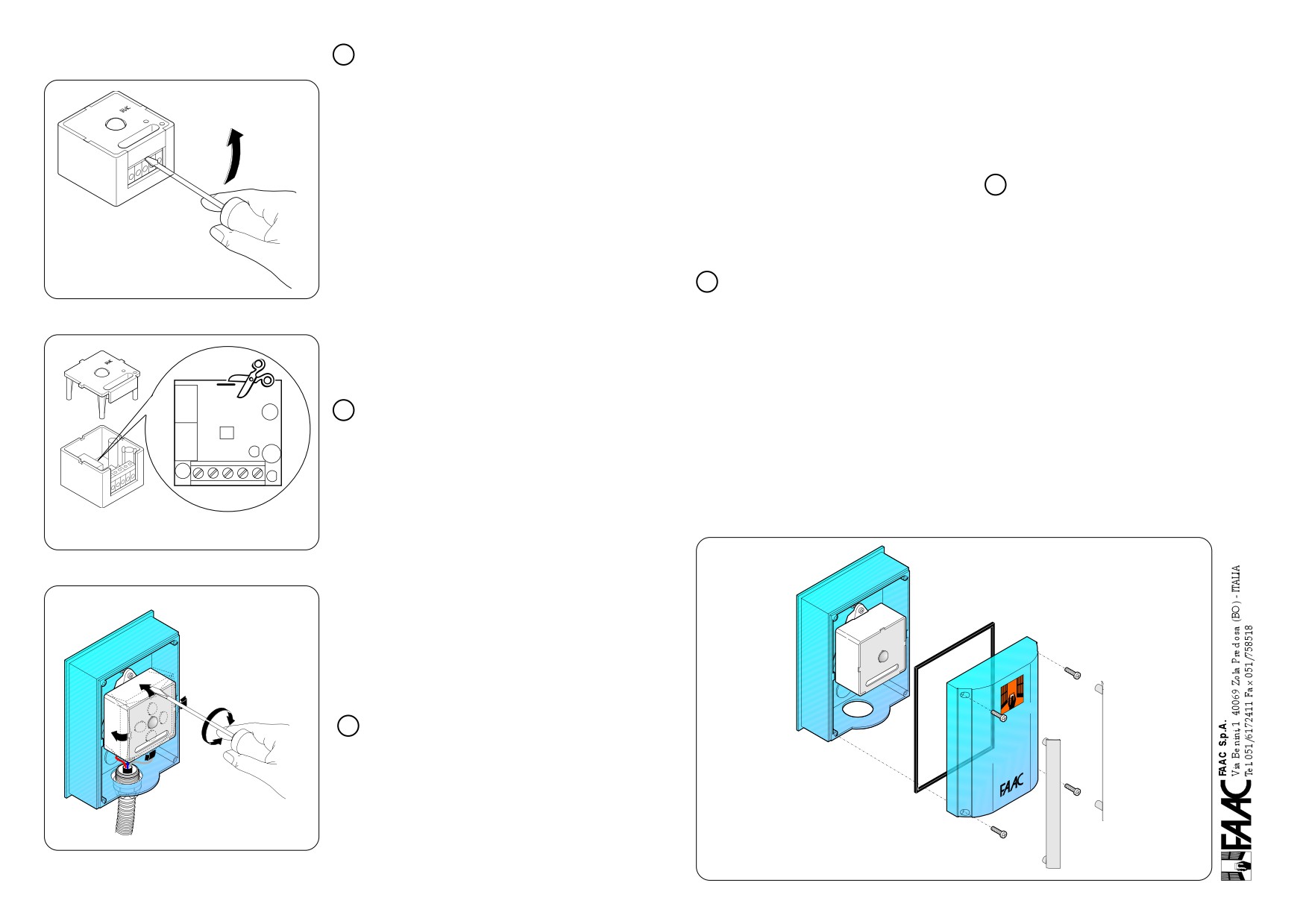
a Facendo delicatamente leva con un cacciavi-
индикатор DL2 на приёмнике начнёт моргать
(Abb. 8) festziehen.
te (fig.6) sollevare il coperchio del Ricevitore.
быстро (рис. 4)
h Zum Abschluß der Installation die Photobeam
b Tagliare il ponticello LK1 (fig.7).
Ü Оптимальная центровка, когда моргание так
mit den zugehörigen Teilen (Abb. 9) schließen.
c Rimontare il coperchio.
часто, как будто индигатор горит.
g После завершения центровки затяните винты
d Alimentare la fotocellula verificando l’accen-
E
3. ALLINEAMENTO
(рис. 8).
sione del Led DL1 sul Ricevitore (fig.4) e sul Trasmet-
ÜSi la distancia entre el Receptor y el Transmisor
h Соберите корпус фотоэлементов (рис.9).
titore (fig.5).
es menor de 15 metros, no sigan los puntos a,b,c
RX
e Allineare manualmente il Ricevitore e il Trasmet-
pasen directamente al punto d.
titore orientandoli in senso verticale e orizzontale,
cercando la posizione in cui il Led DL2 sul Ricevito-
a Haciendo palanca delicadamente con un
re (fig. 4) inizia a lampeggiare sempre più veloce-
destornillador (fig. 6) levantar la tapa del Receptor.
F
mente.
D
b Cortar el puentecito LK1 (fig. 7).
3. FLUCHTUNG
ÜL’allineamento ottimale si ha quando la frequen-
c Volver a montar la tapa.
ÜWenn der Abstand zwischen dem Empfänger und
za di lampeggio è tale da mantenere il Led acce-
dem Sender weniger als 15 m beträgt, die
d Alimentar la fotocélula verificando que el Di-
so.
Arbeitsschritte a,b,c überspringen und direkt mit
spositivo luminoso DL1 se enciende en el Receptor
g Effettuato l’allineamento, serrare la vite di fis-
Punkt d beginnen.
(fig. 4) y en el Transmisor (fig. 5).
saggio (fig.8).
e Alinear manualmente el Receptor y el Transmisor
h Assemblare la Photobeam mediante i partico-
a Den Deckel des Empfängers abnehmen, indem
orientándolos en sentido vertical y horizontal, bu-
lari a corredo (fig.9).
man vorsichtig einen Schraubendreher (Abb. 6) als
scando la posición en la que el Dispositivo lumino-
LK1
Hebel benutzt.
so DL2 del Receptor (fig. 4) empieza a iluminar
b Die Brücke LK1 (Abb. 7) durchtrennen.
GB
3. ALIGNMENT
intermitentemente siempre más rápido.
c Den Deckel wieder anbringen.
ÜIf the distance between Receiver and Transmitter
ÜEl mejor alineamiento se da cuando la
is less than 15 metres, do not carry out points a,
d Die Lichtschranke speisen und sicherstellen, daß
frecuencia de la intermitencia es capaz de man-
b,c but go directly to point d.
die LED DL1 auf dem Empfänger (Abb. 4) und
tener el Dispositivo luminoso encendido.
dem Sender (Abb. 5) aufleuchtet.
g Realizado el alineamiento, apretar el tornillo de
a Lift the cover of the Receiver by levering slightly
e Empfänger und Sender von Hand senkrecht
sujección (fig. 8).
with a screwdriver (fig.6).
und waagrecht ausrichten und hierbei die
h Ensamblar la Photobeam con los accesorios
b Cut the jumper LK1 (fig.7).
Stellung suchen, in der die LED DL2 auf dem
del equipo (fig. 9).
RX
c Refit the cover.
G
d Energise the photocell and check that LED DL1
is lit on both Receiver (fig.4) and Transmitter (fig.5).
e Align the Receiver and Transmitter manually by
pointing in a vertical and horizontal direction, whilst
seeking the position in which the LED DL2 on the
Receiver (fig. 4) begins flashing ever more rapidly.
ÜOptimum alignment is obtained when the
flashing frequency is such as to keep the LED lit.
g Having completed alignment, tighten the fixing
screws (fig. 8).
h Assemble the Photobeam using the compo-
nents supplied (fig.9).
RU 3. ЦЕНТРОВКА
ÜЕсли расстояние между приёмником и
передатчиком меньше 15 метров, то
пункты a,b,c выполнять не надо, следуйте
сразу к пункту d .
a Снимите крышку приёмника при помощи
отвёртки (рис.6).
H
b Перережте перемычку LK1 (рис.7).
c Установите крышку на место.
9