HC Series Card-type PLC. Digital Module User Manual
Contents
1. Product Model List and Dimension
3
2. Indicator Description
4
3. Power Supply Specification
4
4. Environmental Specifications for Product
4
5. Digital Input (DI) Specification
4
6. Digital Output (DO) Specification
4
7. Digital Input/Output (DI/DO) Wiring Diagram
5
8. Terminal Wiring Diagram
5
9. Module Parameter Table
5
10. Extend module Installation
6
2/6
Digital module user manual
1.
Product Model List and Dimension
Model
power(24V)
Dimensions
AE-8X
DC24V~0.1A MAX
AE-8Y-R
DC24V~0.2A MAX
AE-8Y-TN
DC24V~0.2A MAX
AE-8Y-TP
DC24V~0.2A MAX
AE-4X4Y-R
DC24V~0.1A MAX
AE-4X4Y-TN
DC24V~0.1A MAX
AE-4X4Y-TP
DC24V~0.1A MAX
25*95*68
AE-16X
DC24V~0.1A MAX
AE-16Y-R
DC24V~0.35A MAX
AE-16Y-TN
DC24V~0.35A MAX
AE-16Y-TP
DC24V~0.35A MAX
AE-8X8Y-R
DC24V~0.2A MAX
AE-8X8Y-TN
DC24V~0.2A MAX
AE-8X8Y-TP
DC24V~0.2A MAX
14.0
65.0
25.0
6
2
7
1
PWR
0
1
2
3
RUN
4
5
6
7
8
9
10
11
12
13
14
15
3
S/S
X0
4
8
X1
X2
X3
X4
X5
X6
X7
9
X8
S/S
X9
X10
X11
X12
X13
X14
X15
5
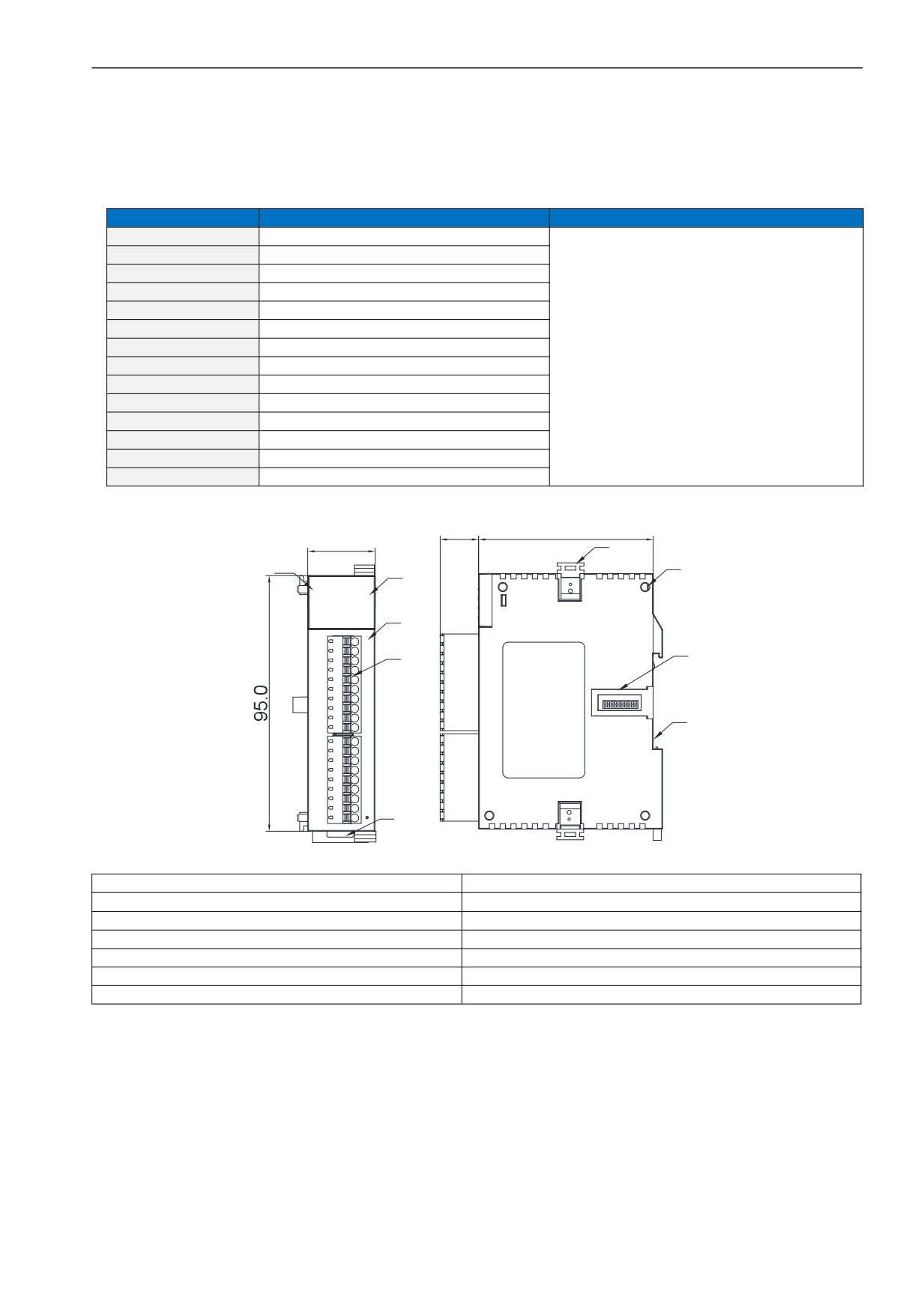
1.Digital channel indicator
8.Module expansion port
2.PWR power indicator、link running indicator
9. 35mm DIN guide rail
3.Terminal definition
4.Removable terminal
5.Rail buckle
6.Module hook
7.Module connection positioning hole
3/6
2. Indicator Description
z
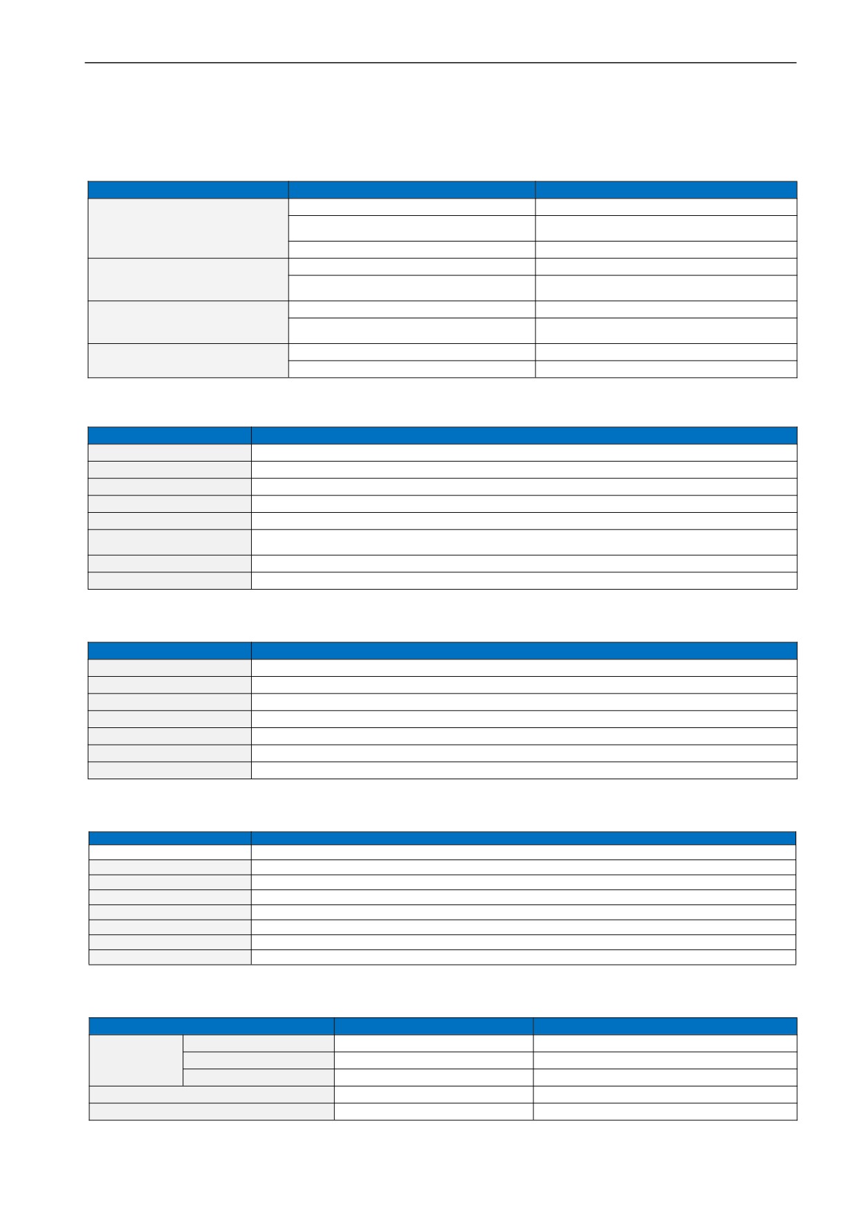
PWR:power indicator .green,constant light -Power normal; Not light - Power abnormal.
z
LINK:multi-status indicator, three colors (Red/ Yellow/ Green), as follow:
Reference processing mode
Module bus state
LINK indicator state
No communication of module
No light
MPU has identified the module but no
Normal
Constant light in green
communication
Serial or parallel port in communication
Green jitter: indicator on 30ms and off 30ms
Without serial or parallel port in communication
Yellow flicker: indicator on 0.5s and off 0.5s
Parallel power supply not enough,
must connect to external power supply
Yellow is darkened and jitter alternately: indicator
With serial or parallel port in communication
off 0.5s and jitter 0.5s
Without serial or parallel port in communication
Red flicker: indicator on 0.5s and off 0.5s
Firmware upgrade failed, reupgrade
Red is darkened and jitter alternately: indicator off
the module firmware
With serial or parallel port in communication
0.5s and jitter 0.5s
Without serial or parallel port in communication
Constant light in red
Hardware failure and maintenance
With serial or parallel port in communication
Red jitter quickly: indicator on 30ms and off 30ms
3.
Power Supply Specification
Item
DC Power Suppl
Power supply voltage
24VDC
-15%~+20%
Power supply frequency
——
Instantaneous surge
MAX 20A 1.5ms @24VDC
Power loss time
10ms or less
Fuse
0.3A,250V
24V Output voltage (for input
None
and expansion
Isolation type
No Electrical isolation
Power protection
DC input power polarity reverse, over voltage protection
4.
Environmental Specifications for Product
Item
Environment Specification
Temperature/Humidity
Operating temperature:0~+55℃ Storage temperature:-25~+70℃ Humidity: 5~95%RH, No condensation
Vibration resistance
10~57 HZ, amplitude=0.075mm, 57HZ~150HZ acceleration=1G, 10 times each for X-axis, Y-axis and Z-axis
Impact resistance
15G, duration=11ms, 6 times each for X-axis, Y-axis and Z-axis
Interference immunity
DC EFT:±2500V Surge:±1000V
Over voltage resistance
1500VAC/1min between AC terminal and PE terminal, 500VAC/1min between DC terminal and PE terminal
Insulation impedance
Between AC terminal and PE terminal @500VDC,>=5MΩ ,all input/output points to PE terminal @500VDC
Operating environment
Avoid dust, moisture, corrosion, electric shock and external shocks
5.
Digital Input (DI) Specification
Item
Environment Specification
Input signal
No voltage contact or NPN/PNP
Action driving
ON>3.5mA OFF<1.5mA
Input impedance
Input Impedance≈4.3KΩ
Maximum input current
10mA
Reaction time
6.4ms DEFAULT, can be configured to 0.8~51.2ms
Isolation type
Independent optoelectronic isolation for each channel
Input indication
LED's lighting indicates ON, no light indicates OFF
Power supply
MPU internal power supply:DC power supply (SINK or SOURCE) 5.3mA@24VDC
6. Digital Output (DO) Specification
Item
Relay output-R
NPN or PNP transistor output-T/P
Resistive Load
2A/1 point, 8A/4 points COM
0.5A/1 point, 2A/4 points COM
Inductive Load
50VA
5W/DC24V
Maximum load
Lamp load
100W
12W/DC24V
Minimum Load
10mA
2mA
Voltage Specification
Below 250VAC, 30VDC
30VDC
4/6
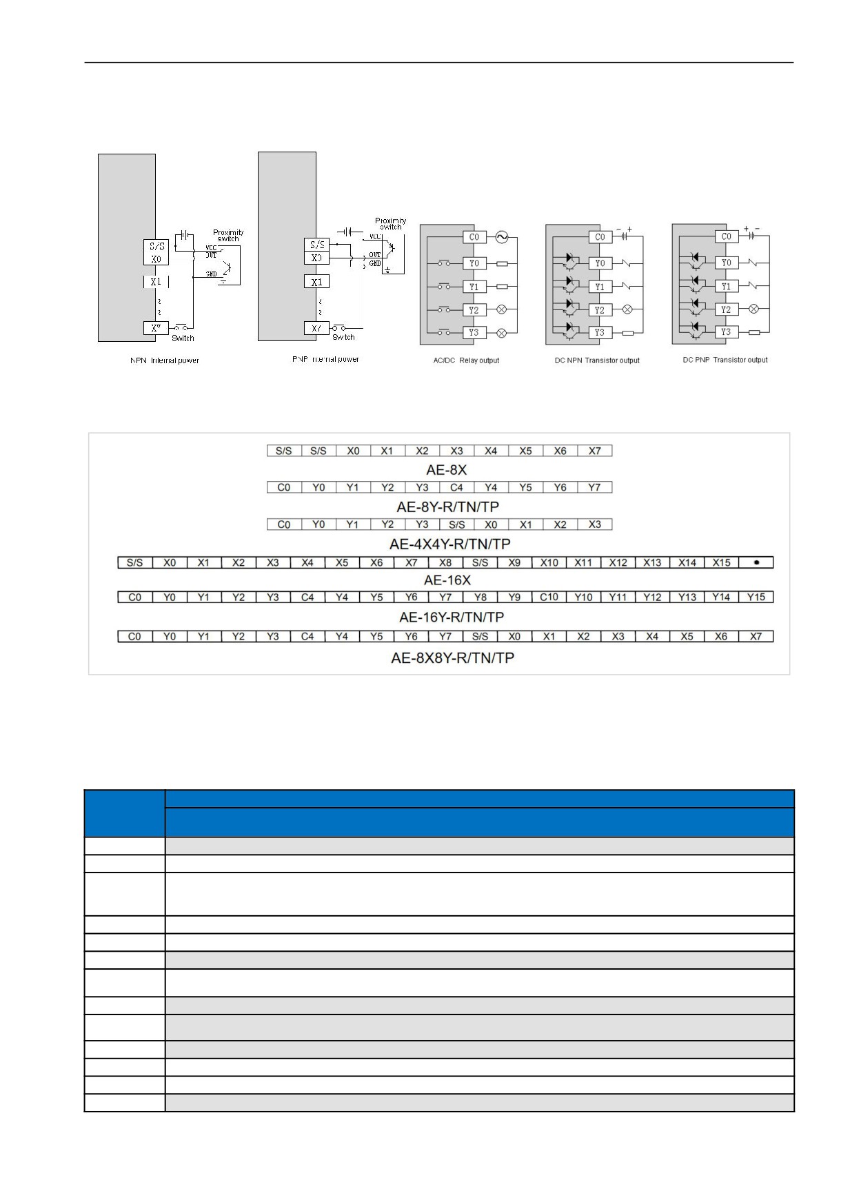
7. Digital Input/Output (DI/DO) Wiring Diagram
8. Terminal Wiring Diagram
9. Module Parameter Table
(CR code is corresponding to the Modbus register address)
Note: CR code is corresponding to the Modbus register address, the gray parts are read-only ,the white parts are readable
and writable.
Function Description
CR No.
AE-8X、AE-8Y-R、AE-8Y-TN、AE-8Y-TP、AE-4X4Y-R、AE-4X4Y-TN、AE-4X4Y-TP、
AE-16X、AE-16Y-R、AE-16Y-TN、AE-16Y-TP、AE-8X8Y-R、AE-8X8Y-TN、AE-8X8Y-TP、
00H
Low byte for module code, and high byte for module version number.
01H
Communication address
Communication protocol: The low 4-bit of the low byte: 0 - N,8,2 For RTU,1 - E,8,1 For RTU,2 - O,8,1 For RTU,3 - N,7,2 For
02H
ASCII,4 - E,7,1 For ASCII,5 - O,7,1 For ASCII,6 - N,8, 1 For RTU
The high 4-bit of the low byte: 0 - 2400,1 - 4800,2 - 9600,3 - 19200,4 - 38400,5 - 57600,6 - 115200
03H~06H
Module name
07H~08H
Default IP address: 192.168.1.111
09~0AH
Reserve
High byte subnet mask (b3~b0,1indicates 255, 0 indicates 0, for example, subnet mask255.255.255.0,b3~b0=1110), low byte
0BH
Reserved
0CH~0EH
Reserve
Error code: 0-Normal, 1-Illegal firmware identity, 2-Incomplete firmware, 3-System data access exception, 4-No external 24V
0FH
power supply
10H~4FH
DI channel 1~64 input value
50H~8FH
DO channel 1~64 output value
90H
DI filter time ms,0 - 0.8、1 - 1.6、2 - 3.2、3 - 6.4、4 - 12.8、5 - 25.6、6 - 51.2
91H~9FH
Reserve
5/6
10. Extend module Installation
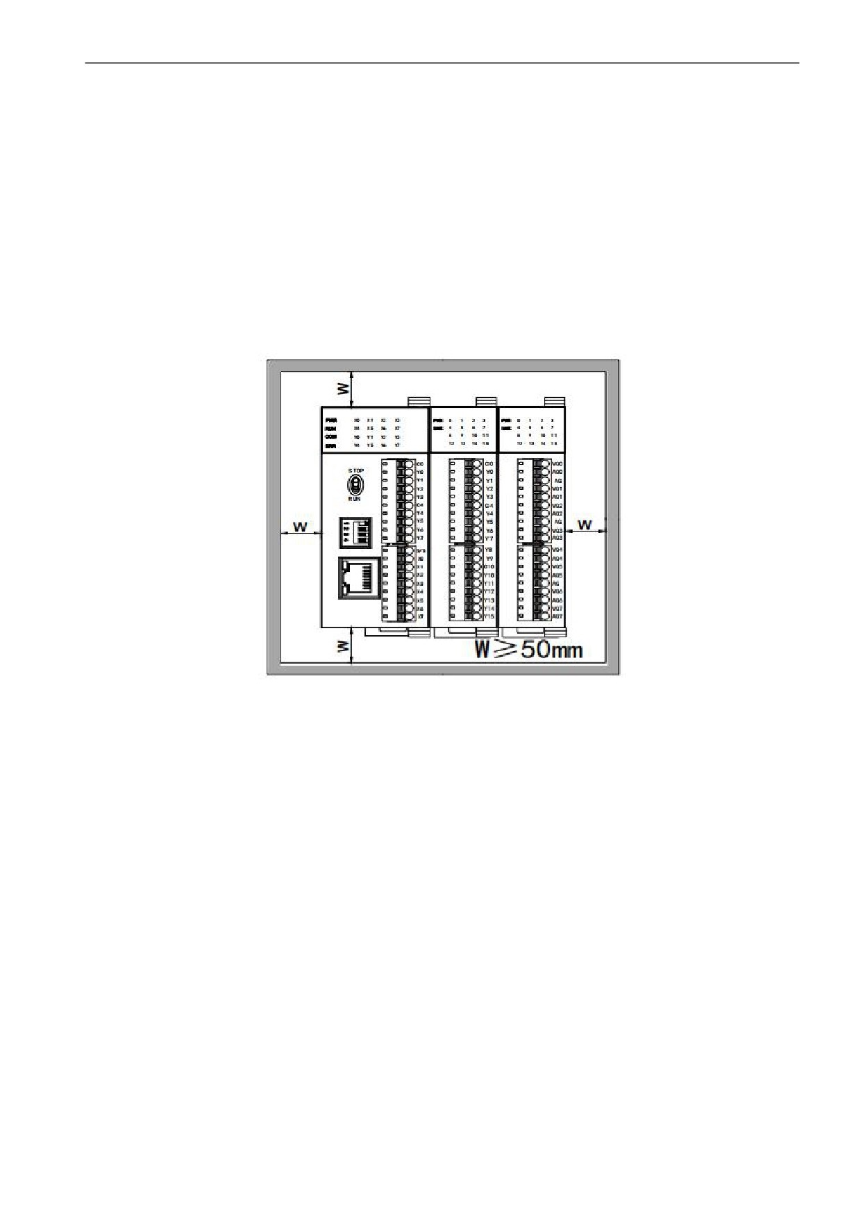
When installing, install it in an enclosed distribution box, and keep a certain space around it (as shown on the right) to ensure
that the PLC can perform heat dissipation。
Rail Mounting: Use standard 35 mm rail.
Extend the connection method of the module
The parallel interface on the lower right side of the previous module (MPU or expansion module) is inserted into the parallel
interface on the lower left side of the next module and hooked with small cards on both sides. The parallel interface on the
right side of this module is used as the next expansion module. Connect all expansion modules in this way in sequence.
Thanks for choosing HNC Products, If you have any questions about our products or services, please let us know!
Website: www.hncelectric.com