HNC PLC User Manual HC Series Card-type PLC. PLC MPU User Manual
HC Series Card-type PLC - MPU user manual
Contents
1. Product Model List & Dimensions
3
2. Indicator Description
4
3. Power Supply Specification
4
4. Environmental specifications for Product
4
5. Digital Input (DI) Specification
4
6. Digital Output (DO) Specification
5
7. Analog Input (AI) Specification
5
8. Analog Output (AQ) Specification
5
9. Digital Input/Output (DI/DO) Wiring
5
10. Analog Input (AI) Wiring Diagram
6
11. Analog Output (AQ) Wiring Diagram
6
12. MPU Terminal Wiring Diagram
6
13. PLC Mounting and installation
6
14. Address Setting
7
15. Power Supply Wiring
7
2/7
HC Series Card-type PLC - MPU user manual
1. Product Model List & Dimensions
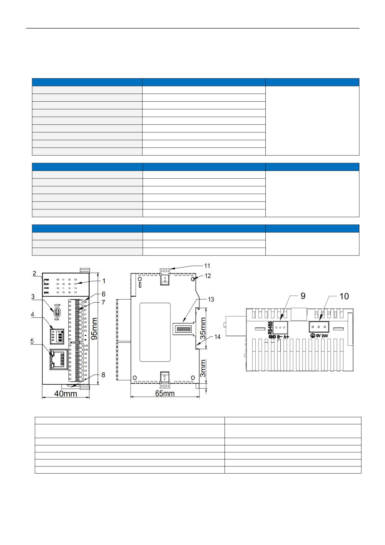
HCS/HCG/HCM Series Model List & Dimensions
HCS series models
Power Consumption(24VDC)
Dimension(W × H × D)
HCS-6X4Y-R
DC24V~0.2A MAX
HCS-6X4Y-TN
DC24V~0.2A MAX
HCS-6X4Y-TP
DC24V~0.2A MAX
HCS-8X8Y-R
DC24V~0.2A MAX
HCS-8X8Y-TN
DC24V~0.2A MAX
40×95×65mm
HCS-8X8Y-TP
DC24V~0.2A MAX
HCS-4X4Y4A-R
DC24V~0.15A MAX
HCS-4X4Y4A-TN
DC24V~0.15A MAX
HCS-4X4Y4ATP
DC24V~0.15A MAX
HCG series models
Power Consumption(24VDC)
Dimension(W × H × D)
HCG-8X8Y-R
DC24V~0.2A MAX
HCG-8X8Y-TN
DC24V~0.2A MAX
HCG-8X8Y-TP
DC24V~0.2A MAX
40×95×65mm
HCG-4X4Y4A-R
DC24V~0.15A MAX
HCG-4X4Y4A-TN
DC24V~0.15A MAX
HCG-4X4Y4A-TP
DC24V~0.15A MAX
HCM series models
Power Consumption(24VDC)
Dimension(W × H × D)
HCM-8X8Y-R
0.2A MAX
HCM-8X8Y-TN
0.2A MAX
40×95×65mm
HCM-8X8Y-TP
0.2A MAX
1. Digital channel indicator
8. Rail clip
1. PWR:Power indicator, RUN:Running indicator,
9. RS485 terminal block
COM:Communication indicator, ERR:Error indicator
2. Running switch
10. DC24V power supply terminal
3. DIP switch
11. Module hook
4. Ethernet port
12. Module connection positioning hole
5. Terminal definition
13. Module expansion port
6. Removable terminal block
14. 35mm DIN rail
3/7
HC Series Card-type PLC - MPU user manual
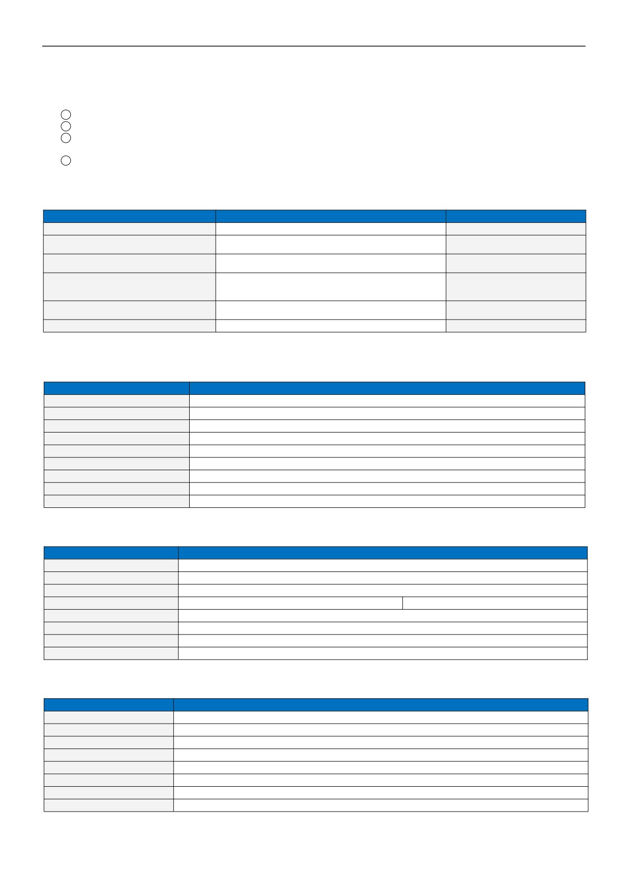
2. Indicator Description
1
PWR: Power indicator,green. Continuous ON - Power good; OFF - Power error.
2
RUN: Running indicator,green. Continuous ON - PLC is in running state; OFF - PLC was shutdown.
3
COM: Communication indicator,green. Flickering - PLC is in communicating state, the flicker frequency indicates the
speed of the communication; OFF - No communication.
4
ERR: Error indicator, red. Continuous ON - Hardware failure; Flickering - Software failure; OFF - Normal state.
According to the different states of the Error indicator, users are recommended to take the following actions:
Reference processing mode
Instruction information classification
ERR indicator status
Normal
No errors
No light
Normal, only remind users to have locked
Flashing yellow: the indicator is on
PLC has data lock components
data
for 0.2s and off for 0.8s
Software setup issues that allow the user program to continue
Flashing yellow: the indicator is on
Modify PLC hardware configuration
running
for 0.2s and off for 0.8s
Check the module parallel bus (check the
Communication between modules is abnormal, and the
Flashing yellow: the indicator is on
RTC battery; check the power supply of the
abnormal module is automatically removed, allowing the user
for 0.8s and off for 0.2s
expansion module)
program to continue to run
Re-upgrade system firmware or modify user
The firmware is abnormal or the user program is abnormal, the
Flashing red: the indicator is on for
program
user program cannot be run.
0.5s and off for 0.5s
Return to factory
Hardware failure, user program cannot be run
Continuous ON
3. Power Supply Specification
Item
DC Power Supply
Power Supply Voltage
DC24V
-15%~+20%
Power Supply Frequency
——
Power Consumption
——
Instantaneous Surge
MAX 20A 1.5ms @24VDC
Allow instant Power Loss Time
10ms or less
Fuse
0.5A,250VAC
5V Output Voltage (for CPU)
5V,-2%~+2%,1.2A(MAX)
Insulation Type
No Electrical isolation
Power Protection
DC input power polarity reverse, over voltage protection
4. Environmental specifications for Product
Item
Environment Specification
Temperature/Humidity
Operating temperature:0~+55℃ Storage temperature:-25~+70℃ Humidity: 5~95%RH, No condensation
Vibration Resistance
10~57 HZ, amplitude=0.075mm, 57HZ~150HZ acceleration=1G, 10 times each for X-axis, Y-axis and Z-axis
Impact Resistance
15G, duration=11ms, 6 times each for X-axis, Y-axis and Z-axis
Interference Immunity
AC EFT:±2500V Surge:±2500V
DC EFT:±2500V Surge:±1000V
Over Voltage Resistance
1500VAC/1min between AC terminal and PE terminal, 500VAC/1min between DC terminal and PE terminal
Insulation Impedance
≧5MΩbetween AC terminal and all input/output points to PE terminal @500VDC
Ground
The third kind of grounding(Connecting to the ground of high voltage system is prohibited)
Operating environment
Avoid dust, moisture, corrosion, electric shock and external shocks
5. Digital Input (DI) Specification
Item
Digital Input (DI)
Input Signal
No voltage contact or NPN/PNP
Action driving
ON>3.5mA OFF<1.5mA
Input Impedance
Input Impedance≈4.3KΩ
Maximum Input Current
10mA
Reaction Time
6.4ms DEFAULT, can be configured to 0.8~51.2ms
Insulation Type
Optoelectronic isolation for each channel
Input Indication
LED's lighting indicates ON, no light indicates OFF
Power supply
MPU internal power supply:DC power supply (SINK or SOURCE) 5.3mA@24VDC
4/7
HC Series Card-type PLC - MPU user manual
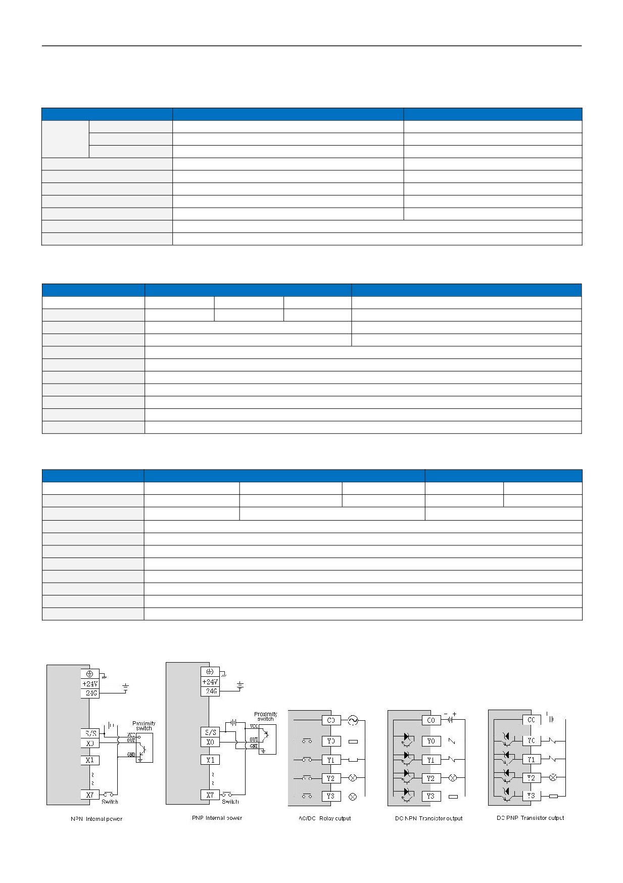
6. Digital Output (DO) Specification
Item
Output point type : Relay - R
NPN or PNP transistor output T/P
Resistive Load
2A/1 point, 8A/4 points COM
0.5A/1 point, 2A/4 points COM
Maximum
Inductive Load
50VA
5W/DC24V
load
Lamp load
100W
12W/DC24V
Minimum Load
10mA
2mA
Voltage Specification
Below 250VAC, 30VDC
30VDC
Drive Capability
Maximum contact capacity: 5A/250VAC
1A MAX, 10 seconds
Reaction Time
Off→On 10ms, On→off 5ms
Off→On 10μs, On→Off 120μs
Insulation Type
Mechanical isolation
Optoelectronic isolation for each channel
Output Indication
LED's lighting indicates ON, no light indicates OFF
Power Supply
MPU internal 24VDC power supply
7. Analog Input (AI) Specification
Item
Voltage Input
Current Input
Input range
0V~+10V
0V~+5V
1V~+5V
0~20mA
4~20mA
Resolution
2.5mV
1.25mV
1.25mV
5μA
Input impedance
6MΩ
250Ω
Max input range
±13V
±30mA
Input indication
LED light means normal, dark means break OFF
Response time
5ms/4 channel
Digital input range
12 bits,Code range::0~32000
Precision
0.2% F.S
Power supply input
MPU use internal power supply, Extension module use external power supply 24VDC ±10% 5VA
Isolation mode
Opto-electric isolation, Non-isolation between Channel ,between analog and digital is opto-electric isolation
Power consumption
24VDC ±20%,100mA(Max)
8. Analog Output (AQ) Specification
Item
Voltage Output
Current Output
Output range
0V~ +10V
0V~+5V
1V~+5V
0~20mA
4~20mA
Resolution
2.5mV
1.25mV
1.25mV
5μA
5μA
Output load impedance
1KΩ@10V
≥500Ω@10V
≤500Ω
Output indication
LED light means normal
Drive capability
10mA
Response time
3ms
Digital output range
12 bits, Code range: 0~32000
Precision
0.2% F.S
Power supply input
MPU use internal power supply, Extension module use external power supply 24VDC ±10% 5VA
Isolation mode
Opto-electric isolation, Non-isolation between Channel ,between analog and digital is opto-electric isolation
Power consumption
24VDC ±20%,100mA(Max)
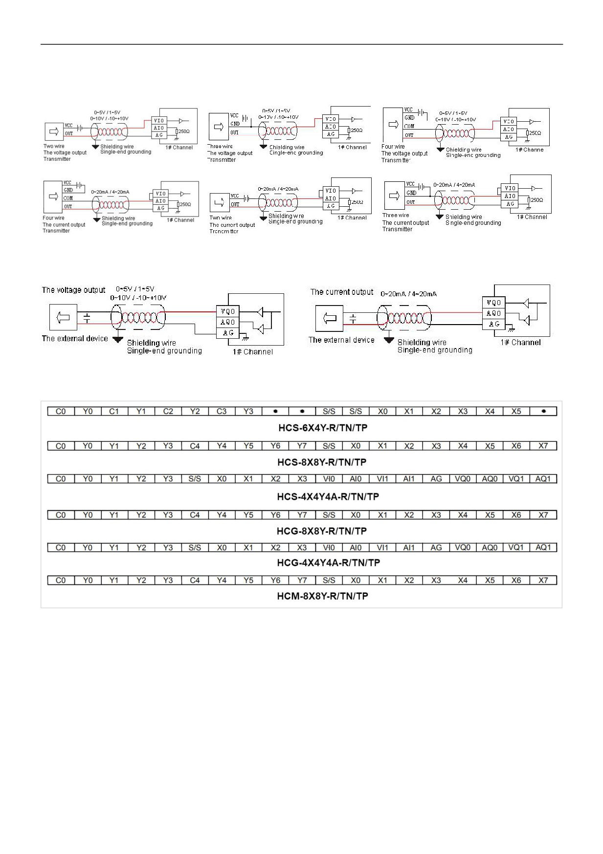
9. Digital Input/Output (DI/DO) Wiring
5/7
HC Series Card-type PLC - MPU user manual
10. Analog Input (AI) Wiring Diagram
11. Analog Output (AQ) Wiring Diagram
12. MPU Terminal Wiring Diagram
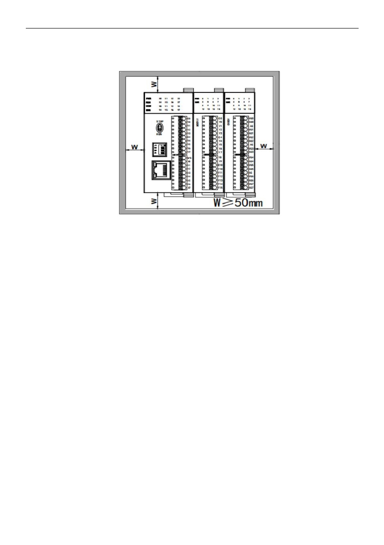
13. PLC Mounting and installation
The PLC should be secured to an enclosed cabinet while mounting. For heat dissipation, make sure to provide a minimum
clearance of 50mm between the unit and all sides of the cabinet. (See the figure.)
PLC installation methods are divided into: rail installation and screw installation.
Rail mounting method: Use standard 35mm rail.
A series expansion module connection method
The connection between the expansion module and the host or between the expansion module and the expansion module is
realized through a parallel port.
Connection method: The parallel port on the lower right side of the previous module (host or expansion module) is inserted into
the parallel port on the lower left side of the next module and hooked with small card hooks on both sides. The parallel port on the
6/7
HC Series Card-type PLC - MPU user manual
right side of this module is used for connected with the next expansion module. In this way, connect all expansion modules in
sequence.
14. Address Setting
MPU with Ethernet port, the default IP address is : 192.168.1.111, subnet mask: 255.255.255.0, gateway:
192.168.1.1. Hardware DIP dial switch address range: 1-15, the default address is 1.
If you need to set a bigger address range, you can set on the software after connection with PLC, it can be
set on the PLC parameter option in the software menu by checking on the "soft address" with the range of
1-254 (the soft address is prior to the hardware dial address).
15. Power Supply Wiring
z
PLC power input is DC input
z
If AC110V or AC220V is connected to + 24V terminal or input point terminal, the PLC will be damaged. Users should pay
special attention.