HHS Series High Performance Soft Starter. Operation Manual (V1.1)
Excellent performance
z Multi start mode:
The maximum output torque can be obtained by the voltage ramp mode. The
maximum current can be obtained by the constant current soft starter mode, which can be
applied to the load with large static friction force
z High reliability:
The high performance microprocessor is used to process the signal in the control
system, so as to avoid the excessive adjustment of the analog circuit in the past, so as to
obtain excellent accuracy and execution speed
z High performance:
Programmable delay start mode, programmable interlocks control
No sequence requirements for input power
Starting time, parking time can be modified
Dynamic fault memory function, easy to find the cause of the fault, up to ten faults can
be recorded
z Field bus full dynamic control monitoring starter, easy networking:
Bus type is MODBUS.
z With a variety of protection functions:
Protection against over voltage, under voltage, over temperature, phase loss, motor
overload, etc.。
z English character display function:
LCD display a variety of operating parameters, programming and fault state with text
prompts
z Perfect humanized design:
Beautiful appearance and reasonable structure
Perfect function and simple operation
Solid, reliable and compact
The artistic design of industrial products
z Reliable quality assurance:
Computer simulation design
STM patch production process
Excellent electromagnetic compatibility
High temperature aging, vibration test before the factory
z Quick and thoughtful after-sales service:
Reliable performance and quality lay the foundation for quality service
- 4 -
Provide excellent and complete equipment design
Timely and thoughtful use of consulting
Continuously improve product performance according to user opinion
- 5 -
Typical application
z Water pump - use soft parking function to stop the pump when the water hammer
phenomenon, saving the cost of system maintenance
z Ball mill - use of voltage ramp start to reduce the wear of the gear torque, reduce
maintenance workload, saving time and saving expenses。
z Fan - reduce belt wear and mechanical impact, saving maintenance costs
z Compressor - use of current limiting, to achieve a smooth start, reduce motor heating,
prolong service life
z Crusher - use of blocking protection and rapid protection to avoid mechanical failure
or blockage caused by overheating of the motor burned
z Transport machinery - through soft starter to achieve smooth and gradual start
process, to avoid product displacement and liquid spills
Use and environmental conditions
z Main circuit power supply:
Three-phase AC 380V or 660V (- 10%, + 15%),
50Hz±0.5%, 60Hz±0.6%
Note: the above data is only applicable to this specification
z Control loop power supply:
Single phase AC220V/380V/460V, 50/60Hz
z Applicable motor: General squirrel cage asynchronous motor
z Starting frequency: Suggest start and stop not more than 20 times per hour
z Cooling: natural cooling
z Installation: wall mounted
z Protection level: IP00 ~ IP20, depending on the power rating, below 55kW is IP20,
55kW and above is IP00
z Environmental conditions: more than 2000 meters above sea level, should reduce the
use of capacity, 5% capacity reduced per every 1000 meters higher.
z The ambient temperature between - 25 ~ 40 ℃.
z Relative humidity is not more than 95% (20c ~ 65C),
z No gel, flammable, explosive, corrosive gas, no conductive dust.
z Indoor installation, good ventilation, vibration less than 0.5g.
- 6 -
Safety precautions
Please read the Descriptions before installing
The soft starter must be installed by professional and technical personnel
The specification of the motor must be matched with the soft starter
It’s strictly prohibited to connect the capacitor at the soft starter output (U, V, W)
After e installation of the exposed terminal must be wrapped with insulating tape
Soft starter or other related equipment shall be grounded reliably
The input power must be cut off when the equipment is repaired
Unauthorized disassembly, modification is forbidden of this product.
- 7 -
CONTENTS
Chapter 1 Introduction of HHS series soft starter
10
1.1 Description of product model
10
1.2 Nameplate specification
10
1.3 Product appearance and installation
12
1.4 Operating panel shape and mounting dimensions
15
1.5 Pallet dimensions and mounting dimensions
15
Chapter 2 Installation
16
2.1 Installation direction
16
2.2 Installation notes
16
2.3 Installation space
16
2.4 Circuit installation
16
Chapter 3 Circuit connection
18
3.1 Working principle of HHS soft starter
18
3.2 Wiring
18
3.2.1 Terminal wiring
19
3.2.2 Connection between product and peripheral devices
20
3.2.3 External control terminal instruction
21
3.2.4 Connection and use of control terminals
22
Chapter 4 Programming instructions
26
4.1 Display and keyboard Description
26
4.2 Function code table and description
27
4.3 Function code description
29
4.4.1 Programming settings
37
Chapter 5 Electric operation
38
5.1 Test run
38
5.2 Running
38
5.3 Running time data display
39
Chapter 6 Fault display
40
6.1 Panel display
40
6.2 Fault code table
40
6.3 Fault memory
41
6.3.1 Display memory failure
41
6.3.2 Fault clearing
42
Chapter 7 Communication protocol
43
7.1 HHS Modbus Protocol Part
43
7.1.1 Overview of Modbus
43
7.1.2 Exception code
43
7.1.3 Register declaration
44
- 8 -
7.1.4 Connection and setting
45
7.1.5 Precautions for use
46
7.1.6 Establishment of communication network
46
Chapter 8 HHS use precautions and routine maintenance
48
8.1 Precautions for use
48
8.2 Daily maintenance of soft starter
49
Schedule 1, Application
50
Schedule 2, Peripheral parts specification parameters
50
Quality Warranty
53
- 9 -
Chapter 1 Introduction of HHS series soft starter
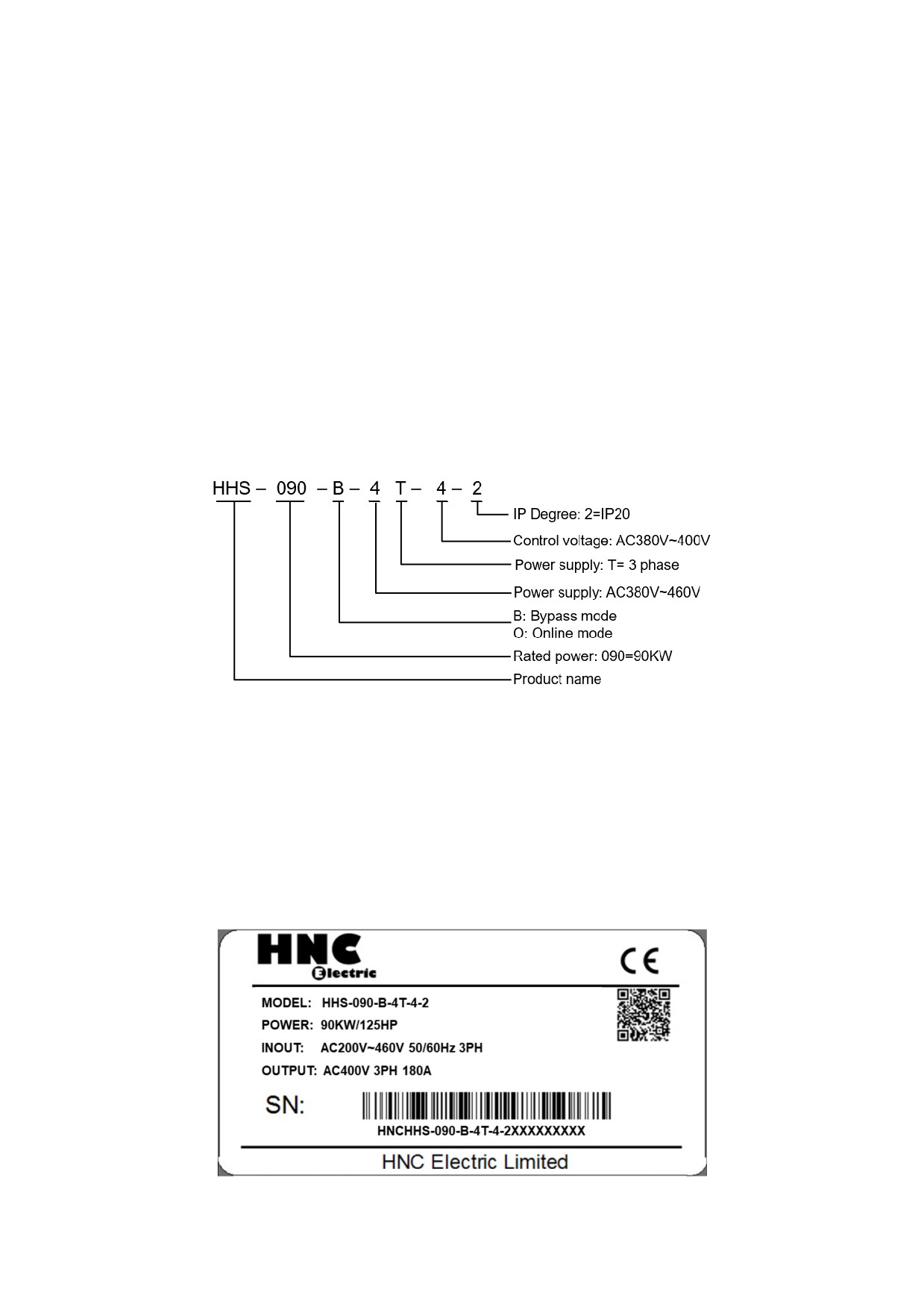
1.1 Description of product model
When open the box, please confirm: whether there is damage or scratch damage
phenomenon in transportation, the nameplate rating is consistent with your order, if there
is please contact the supplier or direct contact with me bad.
The soft starting type column plate numbers and letters product series, power level,
power level and other information.
Soft starter model description:
Note:
Control voltage supports: Single phase AC220 / AV380V / AC460V 50/60Hz
1.2 Nameplate specification
Please check the nameplate on the product to make sure that the goods you received
are in conformity with the goods you ordered
- 10 -
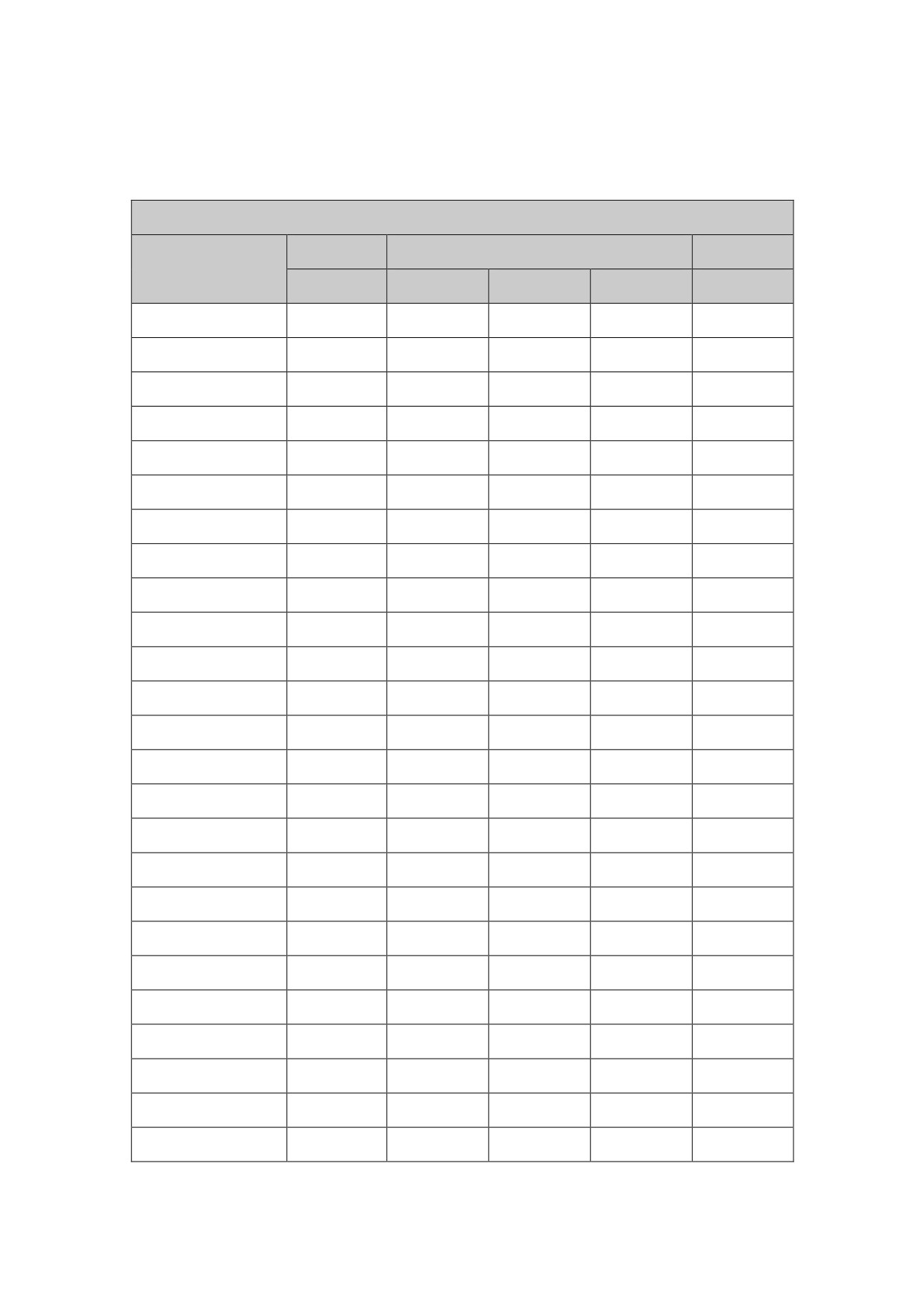
Selection table:
Three phase input & output
Voltage
Power(Kw)
Current
Model No.
(V)
AC220V
AC380V
AC460V
(A)
400
-
5.5
5.5
HHS-5R5-B-4T-4-2
11
400
-
7.5
7.5
HHS-7R5-B-4T-4-2
15
400
5.5
11
11
HHS-011-B-4T-4-2
23
400
7.5
15
15
HHS-015-B-4T-4-2
30
400
-
18.5
18.5
HHS-018-B-4T-4-2
37
400
11
22
22
HHS-022-B-4T-4-2
43
400
15
30
30
HHS-030-B-4T-4-2
60
400
18.5
37
37
HHS-037-B-4T-4-2
75
400
22
45
45
HHS-045-B-4T-4-2
90
400
30
55
55
HHS-055-B-4T-4-2
110
400
37
75
75
HHS-075-B-4T-4-2
150
400
45
90
90
HHS-090-B-4T-4-2
180
400
55
110
110
HHS-115-B-4T-4-2
230
400
-
132
132
HHS-132-B-4T-4-2
264
400
75
160
160
HHS-160-B-4T-4-2
320
400
90
185
185
HHS-185-B-4T-4-2
370
400
110
200
200
HHS-200-B-4T-4-2
400
400
132
250
250
HHS-250-B-4T-4-2
500
400
-
280
280
HHS-280-B-4T-4-2
560
400
160
320
320
HHS-320-B-4T-4-2
640
400
185
355
355
HHS-355-B-4T-4-2
710
400
200
400
400
HHS-400-B-4T-4-2
800
400
-
450
450
HHS-450-B-4T-4-2
900
400
250
500
500
HHS-500-B-4T-4-2
1000
400
315
600
600
HHS-600-B-4T-4-2
1200
Note: Rated current refers to line connection.
- 11 -
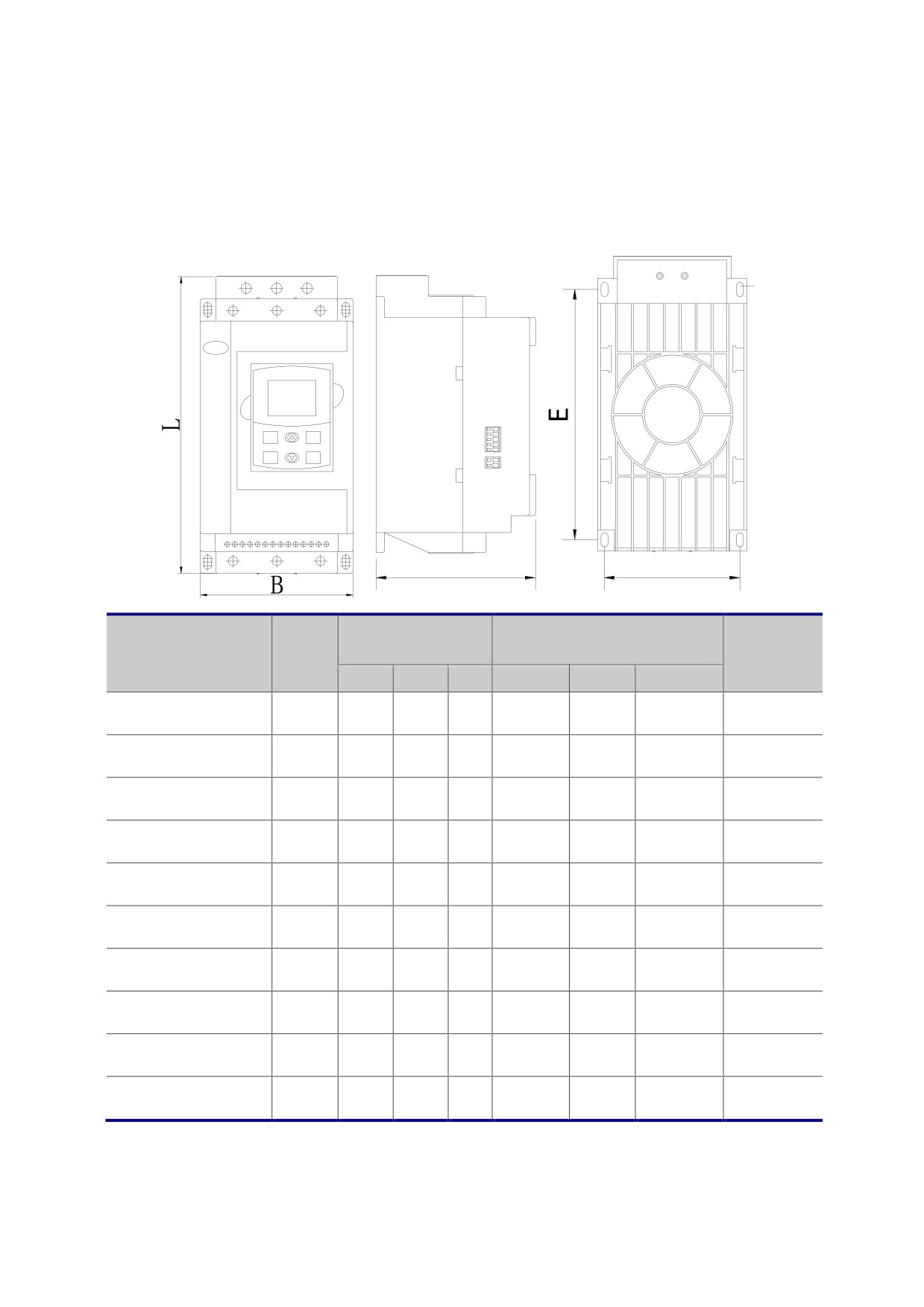
1.3 Product appearance and installation
1、HHS series 5KW-55KW Product size
D
MENU
EXIT
RUN
STOP
H
F
Rated
External
Specifications and
Installation size()
Net weight
curren
dimensions()
models
(kg)
t(A)
L
B
H
E
F
D
HHS-5R5-B-4T-4-2
11
292
152
159
248
131
M7
4
HHS-7R5-B-4T-4-2
15
292
152
159
248
131
M7
4
HHS-011-B-4T-4-2
23
292
152
159
248
131
M7
4
HHS-015-B-4T-4-2
30
292
152
159
248
131
M7
4
HHS-018-B-4T-4-2
37
292
152
159
248
131
M7
4
HHS-022-B-4T-4-2
43
292
152
159
248
131
M7
4
HHS-030-B-4T-4-2
60
292
152
159
248
131
M7
4
HHS-037-B-4T-4-2
75
292
152
159
248
131
M7
4
HHS-045-B-4T-4-2
90
292
152
159
248
131
M7
4
HHS-055-B-4T-4-2
110
292
152
159
248
131
M7
4
Note: Rated current refers to line connection.
- 12 -
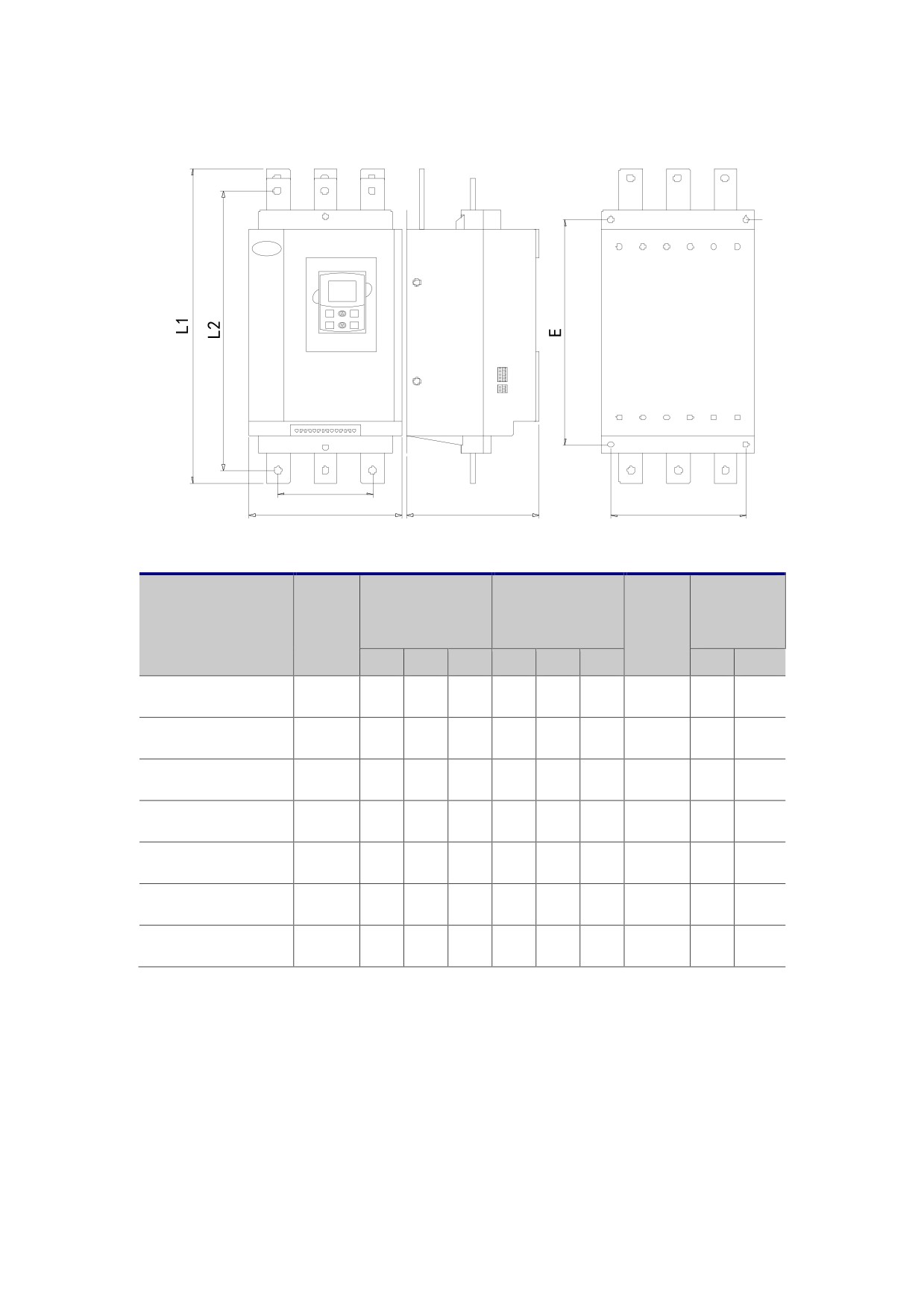
2、HHS series 75KW and above product size
D
MENU
EXIT
RUN
STOP
B1
B
H
F
Copper
Rated
External
Installation size
Net
Specifications and
hole
curren
dimension()
()
weight
models
distance
t(A)
(㎏)
L1
B
H
E
F
D
B1
L2
HHS-075-B-4T-4-2
150
530
260
203
380
196
M8
20
163
439
HHS-090-B-4T-4-2
180
530
260
203
380
196
M8
20
163
439
HHS-115-B-4T-4-2
230
530
260
203
380
196
M8
20
163
439
HHS-132-B-4T-4-2
264
530
260
203
380
196
M8
20
163
439
HHS-160-B-4T-4-2
320
530
260
203
380
196
M8
20
163
439
HHS-185-B-4T-4-2
370
530
260
203
380
196
M8
20
163
439
HHS-200-B-4T-4-2
400
530
260
203
380
196
M8
20
163
439
Note: Rated current refers to line connection.
- 13 -
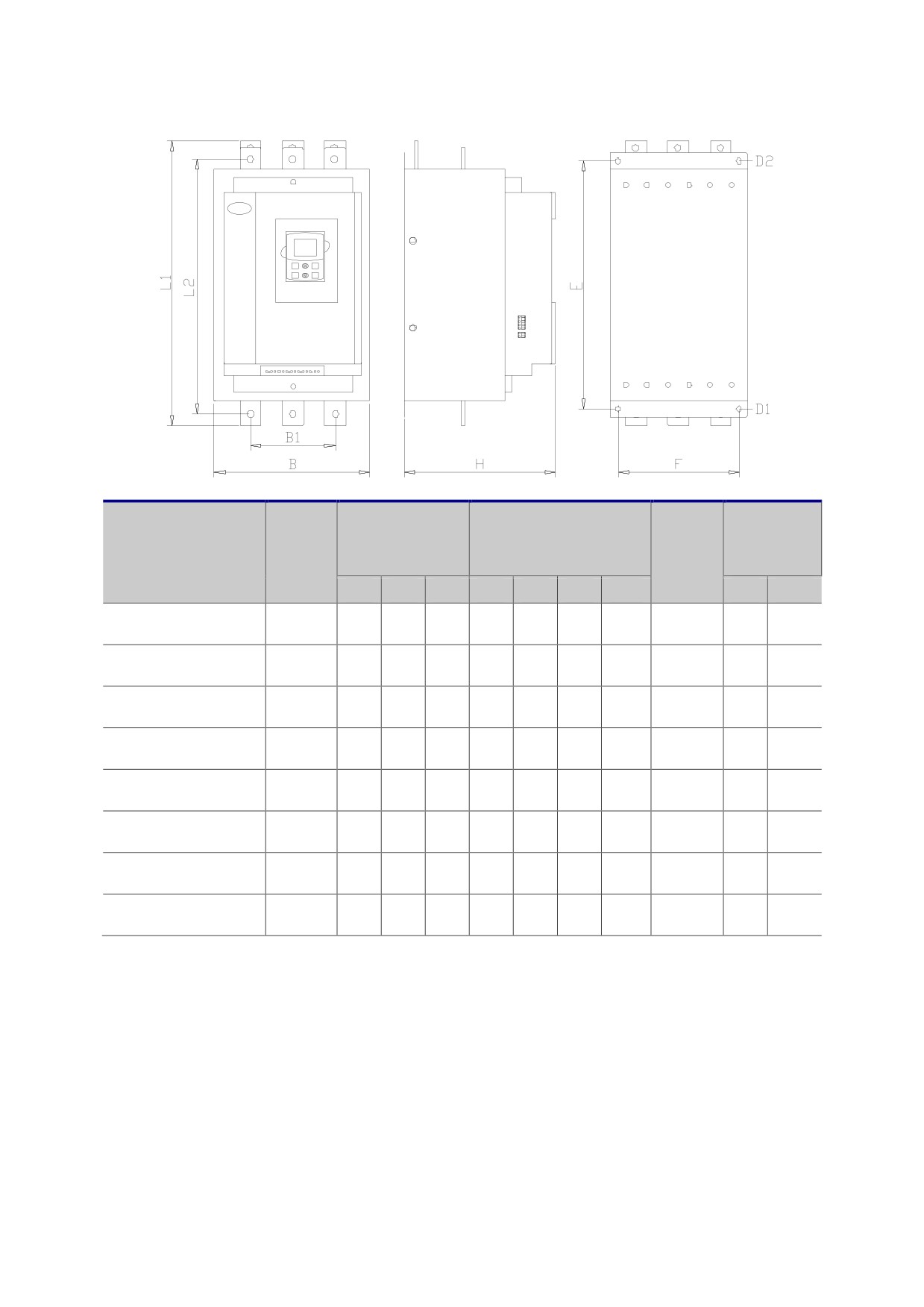
MENU
EXIT
RUN
STOP
Net
Copper
Rated
External
Specifications and
Installation size(mm)
weight
hole
current
dimension()
models
(Kg)
distance
(A)
L1
B
H
E
F
D1
D2
B1
L2
HHS-250-B-4T-4-2
500
570
290
251
465
260
M9
M13
25
180
510
HHS-280-B-4T-4-2
560
570
290
251
465
260
M9
M13
25
180
510
HHS-320-B-4T-4-2
640
570
290
251
465
260
M9
M13
25
180
510
HHS-355-B-4T-4-2
710
570
290
251
465
260
M9
M13
25
180
510
HHS-400-B-4T-4-2
800
660
410
251
550
370
M9
M13
30
HHS-450-B-4T-4-2
900
660
410
251
550
370
M9
M13
30
HHS-500-B-4T-4-2
1000
660
410
251
550
370
M9
M13
30
HHS-600-B-4T-4-2
1200
660
410
251
550
370
M9
M13
30
Note: Rated current refers to line connection.
- 14 -
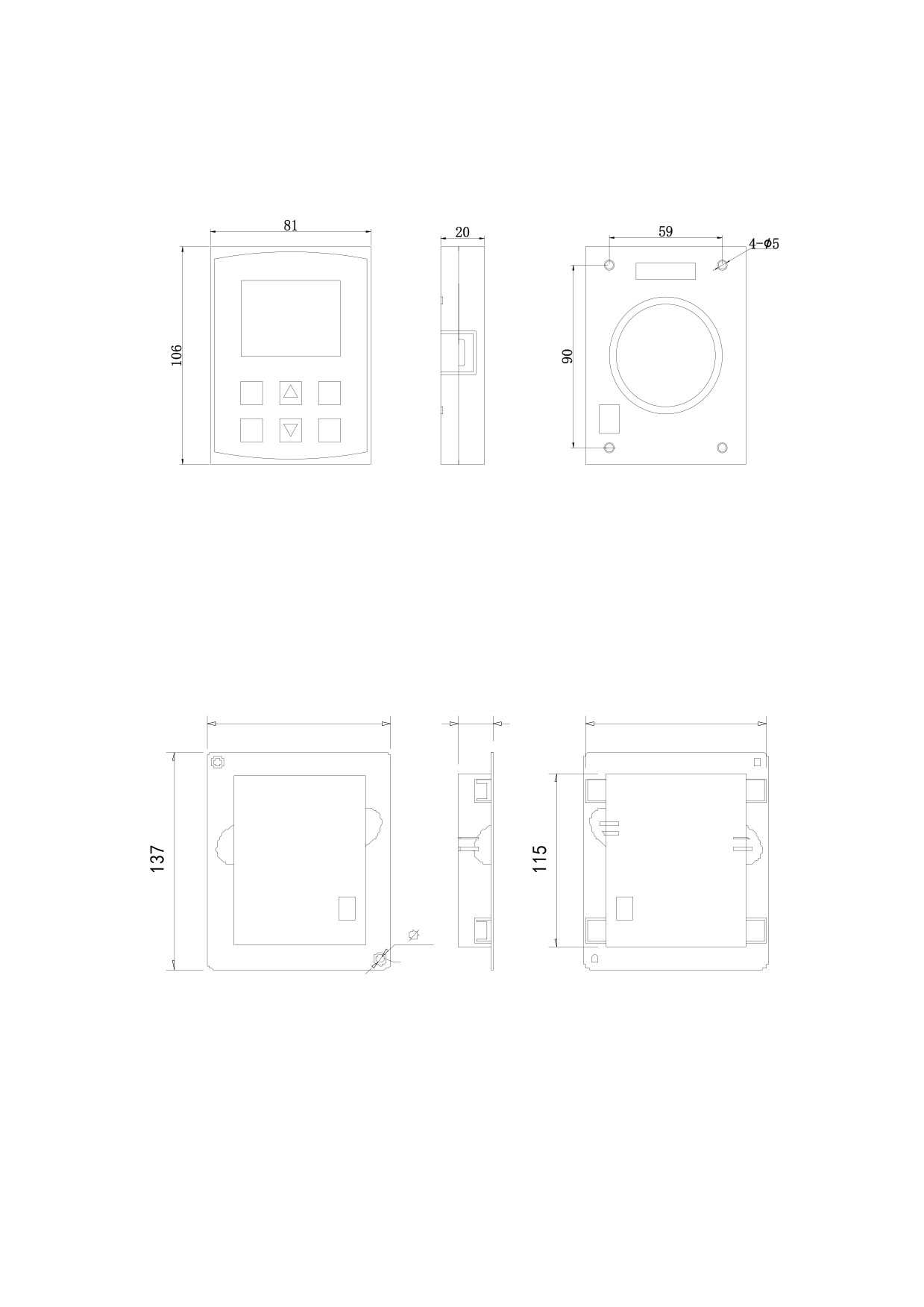
1.4 Operating panel shape and mounting dimensions
MENU
EXIT
RUN
STOP
1.5 Pallet dimensions and mounting dimensions
113
22
111
2-
5
Fixed screw hole
- 15 -
Chapter 2 Installation
2.1 Installation direction
In order to ensure that the soft starter has good ventilation and heat dissipation
conditions, the soft starter should be installed vertically
2.2 Installation notes
z Handling, installation, please holds at the bottom of the product, not only hold the
shell, to prevent the injured foot or broken soft starter.
z Soft starter to be installed in metal and other flame retardant, away from flammable
objects, away from the heat source
z Do not leave the drilling residue in the soft starter when installing the work, otherwise
it may cause the soft start failure
z The soft starter is installed in the cabinet, the cabinet should be equipped with fan, air
vents, and cabinet construction is conducive to heat the internal air duct.
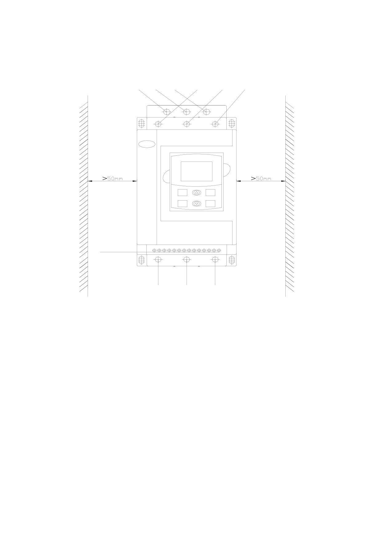
2.3 Installation space
In order to ensure a good heat sink, there should be enough space for the installation
of the soft starter, see Figure 2.1
2.4 Circuit installation
The main circuit adopts the way of going up and down, the wire should ensure sufficient
current capacity, and the selection of wire and peripheral accessories refer to schedule
two
- 16 -
To by pass contactor
R S T 380V Power supply
L21 L22 L23
L21 L22 L23
R
S
T
MENU
EXIT
RUN
STOP
U
V
W
1-6 Control Relay wiring
7-14 Control wiring
Fig 2.1
Note: As shown above fig 2.1, 1-6 and 7-14 are terminals, terminals 1-6 are for control
relay wire, terminals7-14 are for control wire
- 17 -
Chapter 3 Circuit connection
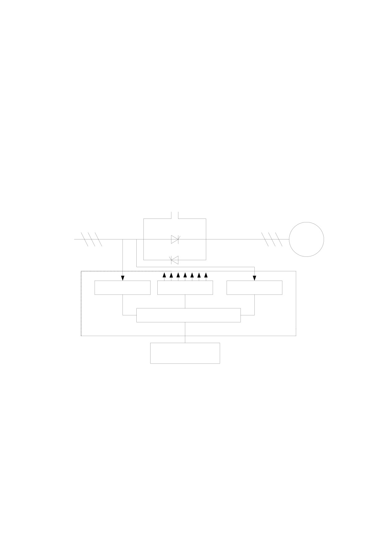
3.1 Working principle of HHS soft starter
The main circuit of HHS motor soft starter with six anti parallel thyristor series stator
circuit connected to the AC motor. The use of electronic switching thyristor, the
microprocessor controls the trigger angle change to change the conduction angle of the
thyristor, thus changing the input voltage of the motor, in order to control the purpose of
motor soft starting. When completed, the soft starter output reaches the rated voltage.
When the control bypass contactor km three-phase pull motor into service. (see Figure
3.1).
KM
R .S .T
U .V .W
electric
motor
three-phase AC
·
380V/ 660V
Phase
drive
Current
detection
circuit
detection
MCU controller
control panel
Operation
keyboard display
Figure 3.1
3.2 Wiring
Figure 3.2 is the HHS series motor soft starter for the user to use all of the external
terminals, detailed functions are shown in table
3.2.4 "external control terminal
Descriptions."
- 18 -
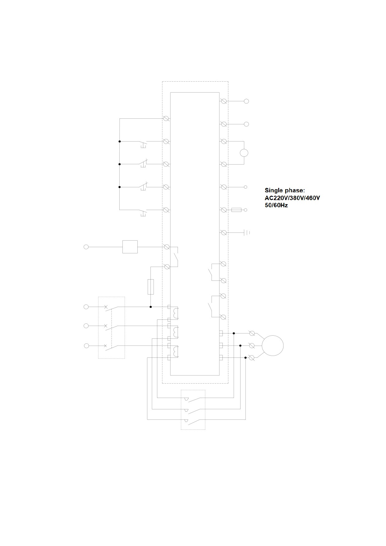
3.2.1 Terminal wiring
B
RS485 interface
11
common port
A
10
X2-2
running
Series
A
4-20mA
soft
9
X2-1
stop
starter
8
14
N
Instantaneous
stop
FU
7
13
L
Reset / lock
12
PE
2
Bypass
N
output
KM(Bypass
K1
6
contactor )
1
K3
Fault
output
5
FU
4
K2
Programmable
L3
T
interlock relay
L23
3
output
L2
S
W
L22
L1
R
V
electric motor
L21
U
QF (circuit
Squirrel cage
breaker)
three-phase
asynchronous motor
KM
(bypass contactor contact)
Figure 3.2
- 19 -
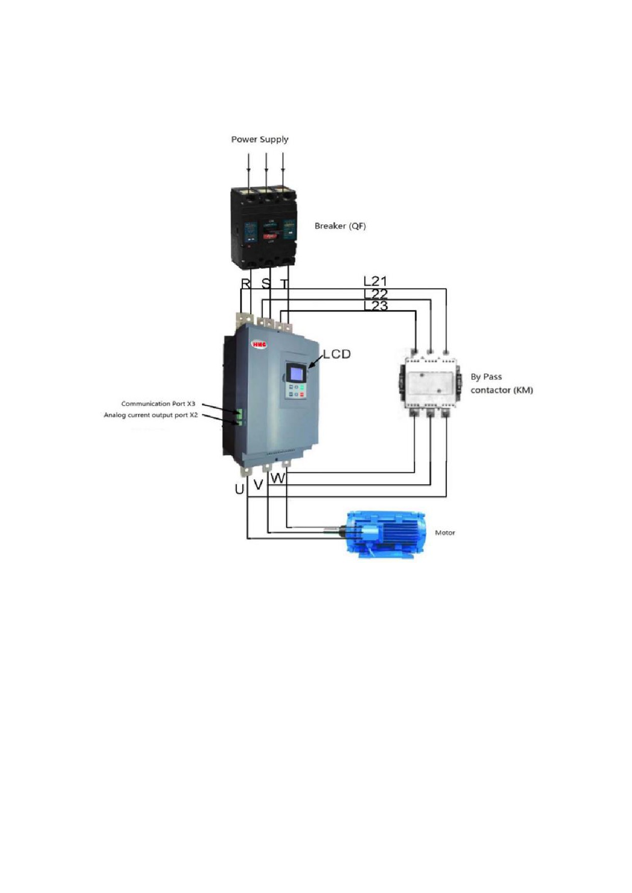
3.2.2 Connection between product and peripheral devices
Figure 3.3
- 20 -
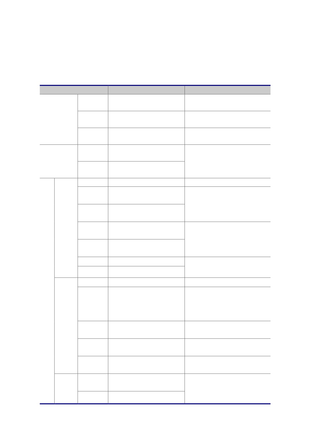
3.2.3 External control terminal instruction
Table 3-1
Terminal symbol
Terminal name
Description
Three phase AC power supply
R.S.T
AC main circuit power input
connected by circuit breaker
Three phase asynchronous
main circuit
U.V.W
Soft starter output terminal
motor
L21.L22.
Special terminal for external
Refer to figure 3.3 for wiring
L23
bypass contactor
control AC power input
Single phase:
X1-13
control
terminal
AC220V;AC380V; AC460V
source
control AC power input
50/60Hz
X1-14
terminal
X1-12
Ground input terminal
ground connection
Bypass contactor input
X1-1
After the start of the closing
terminal
capacity of AC220V 5A
Bypass contactor input
This output is not adjustable.
X1-2
terminal
relay
Programmable relay output
output
X1-3
terminal
See 4.3.11 capacity AC220V 5A
Programmable relay output
by programming control
X1-4
terminal
X1-5
Fault relay output terminal
Capacity AC220V 5A
This output is not adjustable.
X1-6
Fault relay output terminal
con
X1-7
External reset terminal
Fault reset
trol
Stop when the stop and the
circ
External control E-Stop
common end are disconnected,
uit
X1-8
terminal
see 4.3.1. It’s effective also when
start the soft starter from keypad
digital
External control stop
disconnect Stop and the public
input
X1-9
terminal
then Stop effectively
External control starting
The start and the common end
X1-10
terminal
short connection
External digital signal
X1-11
common terminal
Current signal output
Analog
X2-1
4-20mA can program selected,
terminal Positive
current
see 4.3.9
output
X2-2
Current signal output
- 21 -
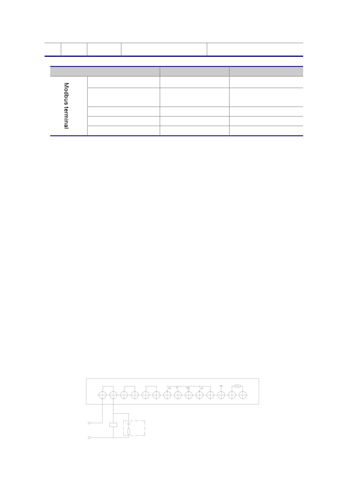
terminal negative
Modbus terminal specification:
Table 3.1 continued
Terminal symbol
Terminal name
Description
X3-1
GND
Power supply terminal
Signal non inverting
X3-2
A
input
X3-3
NC
Idle terminal
X3-4
B
Signal inverting input
X3-5
5V
Positive power terminal
Note: The matching resistance is less than 200 ohms
3.2.4 Connection and use of control terminals
(1) Wiring preparation
If the user uses the external terminal, it is recommended to use the shielded wire
from the terminal row, the shield wire should be connected to the earth.
In order to avoid the interference of electromagnetic interference, the control lead
should avoid the motor cable and other inductive electrical wiring
(2) The connection of the outer terminal x1
The 14 terminal is located at the bottom of the starter, with a dangerous voltage
when it is used, and the power must be disconnected before disconnecting
● Bypass relay terminal 1,2
When the start-up process is completed, the built-in contacts will be closed, so that
the bypass contactor km closed; and when the stop command is issued, the built-in
contacts will open (see Figure 3.4)
It is suggested that the two ends of the coil of the contactor are connected with a
series circuit of resistance capacitance, which is beneficial to absorb the peak voltage
generated when the contactor coil is broken, and reduce the interference to the control
circuit of the starter
Bypass
PRG
Fault RESET EMS STOP RUN COM
380V
1
2
3
4
5
6
7
8
9
10
11
12
13
14
KM
2.2uF
20Ω
Fig. 3.4 Bypass relay terminal
- 22 -
z Programmable relay output terminal 3,4
This contactor is mainly used to connect with other control equipment, can be
programmed to select the output, see 4.3.11. Contactor capacity AC 250V 5A
z Fault output terminal 5,6
This contactor represents the starter or motor failure, normally open, contact capacity
AC 250V 5A
z Reset input terminal 7,11
When the external reset terminal 7 is connected with the public terminal 11, the fault
state can be contacted
z Instantaneous stop input terminal 8,11
Belong to the external fault signal input, can be used for external thermal relay and
other switch quantity protection, only 8 and 11 when connected to the starter can be run,
otherwise the instantaneous stop failure
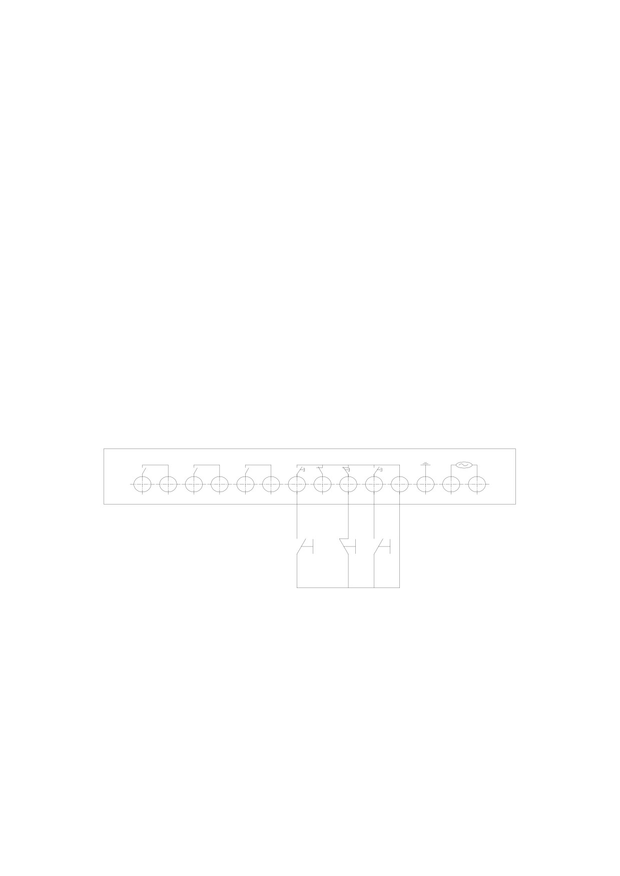
z Control terminal 9 (stop), 10 (start), 11 (com)
These three terminals are used for external start and stop buttons, which must be
programmed when used (see 4.3.1)
Following figure 3.5 shows a three wire connection, often used for external buttons
Bypass
PRG
Fault RESET EMS STOP RUN COM
380V
1
2
3
4
5
6
7
8
9
10
11
12
13
14
reset
stop start
Figure 3.5 three wire connection
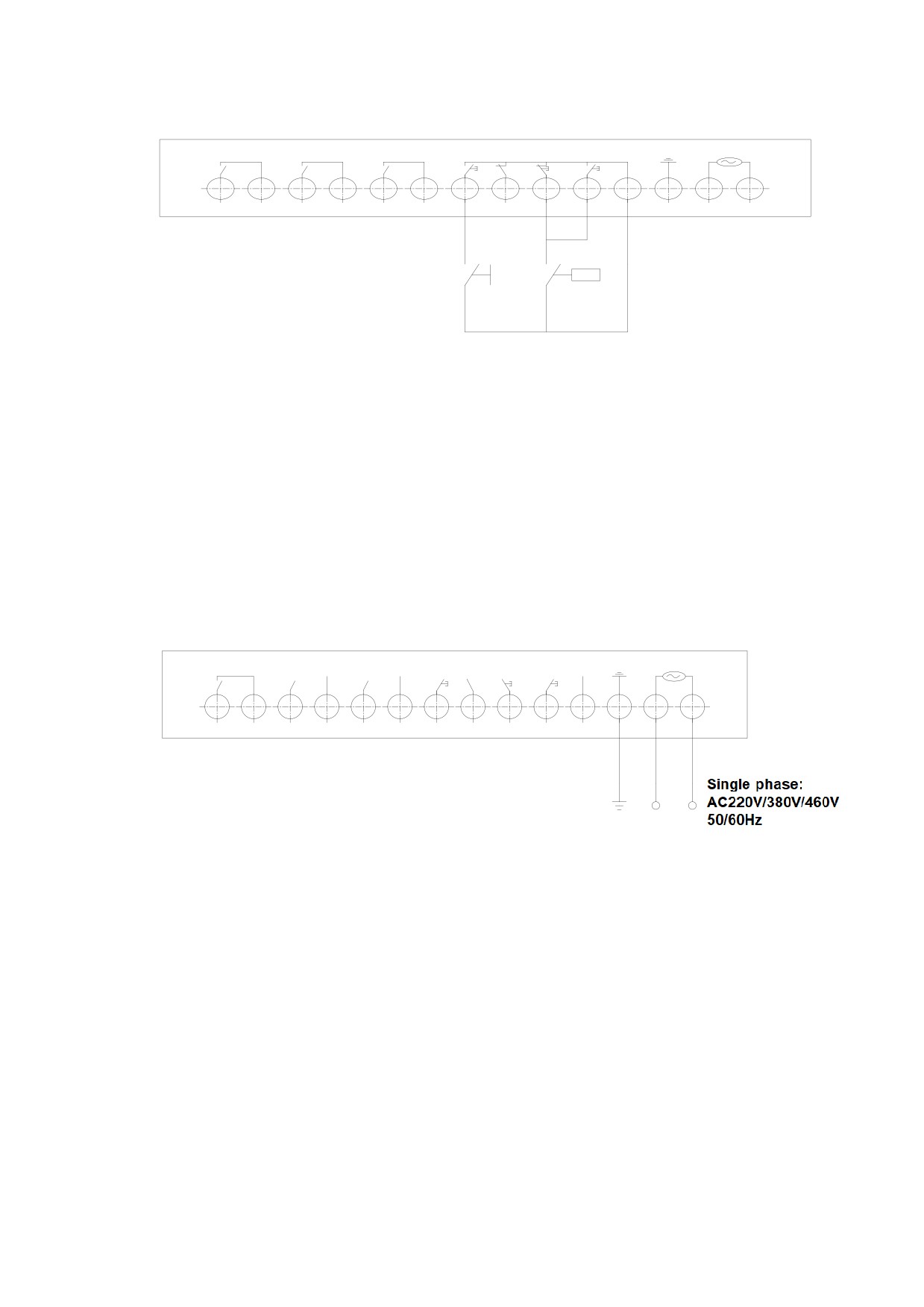
But the following scenarios should be two wire connections: (see Figure 3.6)
(1) when a user needs a switch to control the stop of the starter, such as a control
point of pc/plc J
(2)when the automatic restart function of the soft starter is used, when the j is
closed to start to fail, after a certain period of time, the automatic reset of the starter can
be carried out simultaneously (see 4.3.16)
- 23 -
Bypass
PRG
Fault RESET EMS STOP RUN COM
380V
1
2
3
4
5
6
7
8
9
10
11
12
13
14
J
reset
start/stop
Figure 3.6 two wire connection
z Ground terminal 12
When the ground is installed, the device can be connected to the mounting plate
nearby, and the device above 75kW adopts the shell and the 12 terminal to be grounded
at the same time
z Working power supply terminal 13,14
External 380V power grid voltage, if the 660V soft starter is the main circuit through
the isolation transformer step-down to obtain. (See Figure 3.7)
Bypass
PRG
Fault RESET EMS STOP RUN COM
380V
1
2
3
4
5
6
7
8
9
10
11
12
13
14
Connection
protection
ground wire
L1
L2
Fig. 3.7 working power supply terminal
z Analog current signal terminal X2
On the left side of the starter, there is a two pin terminal, which is used to reflect the
current signal of the main loop current, which is 4 - 20mA, and the output mode can be
programmed
- 24 -
Figure 3.8 shows the use of reference
+
1
R<250Ω
2
-
Figure 3.8
z Bus terminal x3
Select a dedicated field bus cable
- 25 -
Chapter 4 Programming instructions
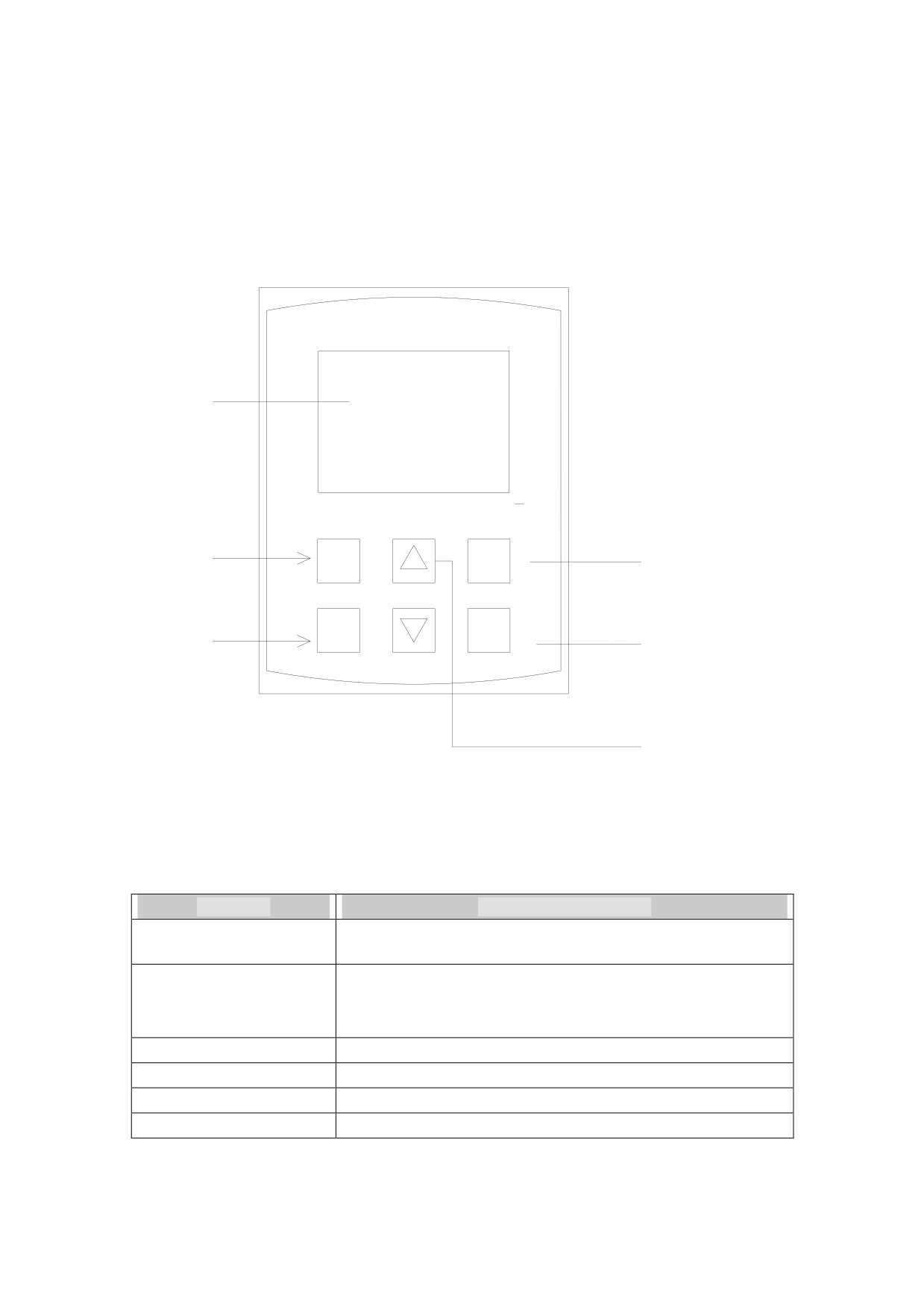
4.1 Display and keyboard Description
HHS Series of soft starter with LCD display, easy to set up the user, read the parameters,
as well as the status of real-time display soft starter
Text area
Menu key
MENU
EXIT
exit key
RUN
STOP
Run key
Stop / reset key
Parameter
modification
Figure 4.1
Figure 4.1 shows the location of each key, as follows:
Key name
Key function description
RUN -Run key
Use this key to enable the motor to run in the ready state
When the motor is running, press this key to enter the
STOP - Stop / reset key
parking。When the fault condition, press this key to return to
the ready state
MENU - Menu key
Used to go to the next menu or store parameter settings
EXIT
- return key
Used to return to the previous menu
▲
- Up key
Used to add data
▼
- Down key
Used to reduce data
- 26 -
4.2 Function code table and description
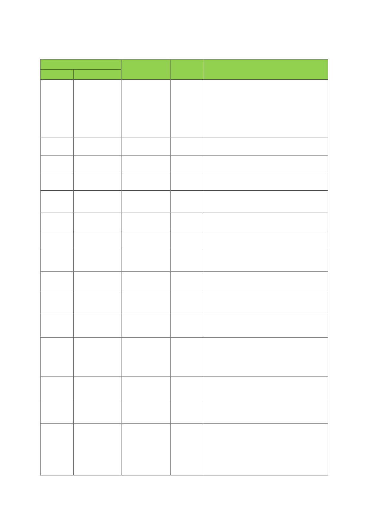
Table 4.1
Function
Default
Setting range
Description
code
name
value
0: keyboard
1: Terminal
2: Modbus
00
Control mode
0-5
0
3: Keyboard + terminal
4: Keyboard + bus
5: Terminal + bus
01
Starting mode
0-1
1
0: Current limit 1: Voltage
02
Current limit
150%-500%
210%
Valid in Current limit mode
03
Initial voltage
25%-80%
30%
Valid in Voltage mode
Valid in Voltage mode and Invalid in
04
Rise time
1-120S
10S
current limit mode
05
Down time
0-60S
0S
0 means free stop
06
Starting delay
0-240S
0
0 means “starting delay” off
0: Disable 1: Enable (Valid in voltage
07
Jump starting
0-1
0
mode)
08
Jump voltage
50-80%
50%
When Pa07 = 1, this parameter is valid
09
Jump time
0.1-1.0S
0.3S
When Pa07 = 1, this parameter is valid
Instantaneous
0A
0-1
0
0: Disable 1: Enable
stop setting
0: 0-20mA 500%
Current signal
1: 0-20mA 150%
0B
0-3
2
selection
2: 4-20mA 500%
3: 4-20mA 150%
Current
0C
0-1
0
0: current value 1: percentage
display
Programming
0 is immediate output, for programmable
0D
0-240S
0
delay
relay output
0 From starting command moment
Programming
1 From starting moment
0E
0-9
7
output
2 bypass running status
3 From stop command moment
- 27 -
4 delay status
5 fault status
6 starting and running
7 ready status
8 starting status
9 running status
Phase loss
0F
0-1
0
0: Enable 1: Disable
protection
Light load
10
0-1
1
0: Disable 1: Enable
protection
Light load
Start protection after full voltage running,
11
50-100%
50%
rate
valid when Pa10 = 1
Over voltage
Protection when actual voltage is higher
12
100-130%
120%
protection
than the setting value
Under voltage
Protection when actual voltage is lower
13
40-90%
80%
protection
than setting value
Primary, light load, standard, heavy load,
14
Trip level
0-4
2
advanced
0: Disable
1: Enable
(Valid on Two
15
Self-starting
0-1
0
wire type mode)
16
Bus address
1-247
1
0: 1200;1: 2400;2: 4800;
17
Baud rate
0-4
3
3: 9600;4: 19200
18
Parity check
0-2
0
0: None
1: odd
2: even
Load
19
regulation
50-100%
100%
rate
write
1A
0-1
0
0: Disable
1: Enable
protection
Language
1B
0-1
1
0: reserved 1: English
selection
100% is rated current of soft starter, if
Current
rated current of motor is different. You
1C
60%-160%
100%
coefficient
can change this value to make them
same
Parameter
Restore
0: Disable
1D
0-1
0
Default
1: Enable
settings
Bypass
0: Enable
1E
0-1
0
function
1: Disable
Note: 1.This function code is keep after power off until next modification.
- 28 -
2. Function code can be modified by the 4.4.2 method to the Default value
3. Function code may vary with the version upgrade, please note that the latest version
of the note
4.3 Function code description
4.3.1 Code 00 (control mode)
0: Keyboard, only Control by RUN and STOP key to start or stop on the panel
1: Terminal, only by the terminal RUN/STOP/COM two wire or three wire starting mode
2: Modbus, (X3 terminal) control monitoring operation
3: Keyboard + terminal (Suitable for 3 wire control mode)
Both the terminal and keyboard can operate, but when the keyboard starting, STOP terminal
Must be connected to COM
4: Keyboard + bus, both the keyboard and bus can control
5: Terminal + bus, Both X1 terminal RUN, STOP and BUS terminal X3 can control
4.3.2 Code 01 (start mode)
0 is current limit mode, starting current limit see 4.3.3
1 is voltage mode, see 4.3.4
4.3.3 Code 02 (current limit)
When using this function, the code 01 must be set to 0, the starting current starter operation
below the set value (150%-500%). When starting after the current drops below the rated value, the
greater the set value, the starting time will be shorter.
U
I1
I2
I3
Ie
T
Figure 4.2
4.3.4 Code 03 (initial voltage) 04 (rise time)
They are the starting control parameters in the voltage mode, and increasing the starting
voltage is beneficial to overcome the static friction force of the load starting, and the longer the
load inertia is, the longer the rise time (see Figure 4.3)
- 29 -
U
Full voltage operation state
voltage curve
starting voltage
Fast ramp
rise time
Ut
Current curve
t
Figure 4.3
4.3.5 Code 05 (Down time)
When the down time is set to 0, it means free stop, and the long downtime will bring instability
to the system (see Figure 4.4)
U
T
Figure 4.4
4.3.6 Code 06 (Starting delay)
The time between the starting command being sent and the starter starts, The soft starter
starts when the countdown shows 0
4.3.7 Code 07 (Jump starting) code 08 (Jump voltage) code of the 09
(Jump time)
When Code 07 is set to 1, Jump starting is effective. In some heavy occasions, due to the
influence of mechanical static friction and not starting motor, can choose this mode. In this mode,
you should shut down the Jump starting, If the motor caused by the static friction force is too large
to rotate, and then choose this mode .Otherwise we should avoid using Jump starting, in order to
reduce the large current impact is not necessary.
4.3.8 Code 0A (instantaneous stop setting)
You can open or close the external control instantaneous stop input EMS, set when 0 is
- 30 -
closed this function, 1 is activate this function
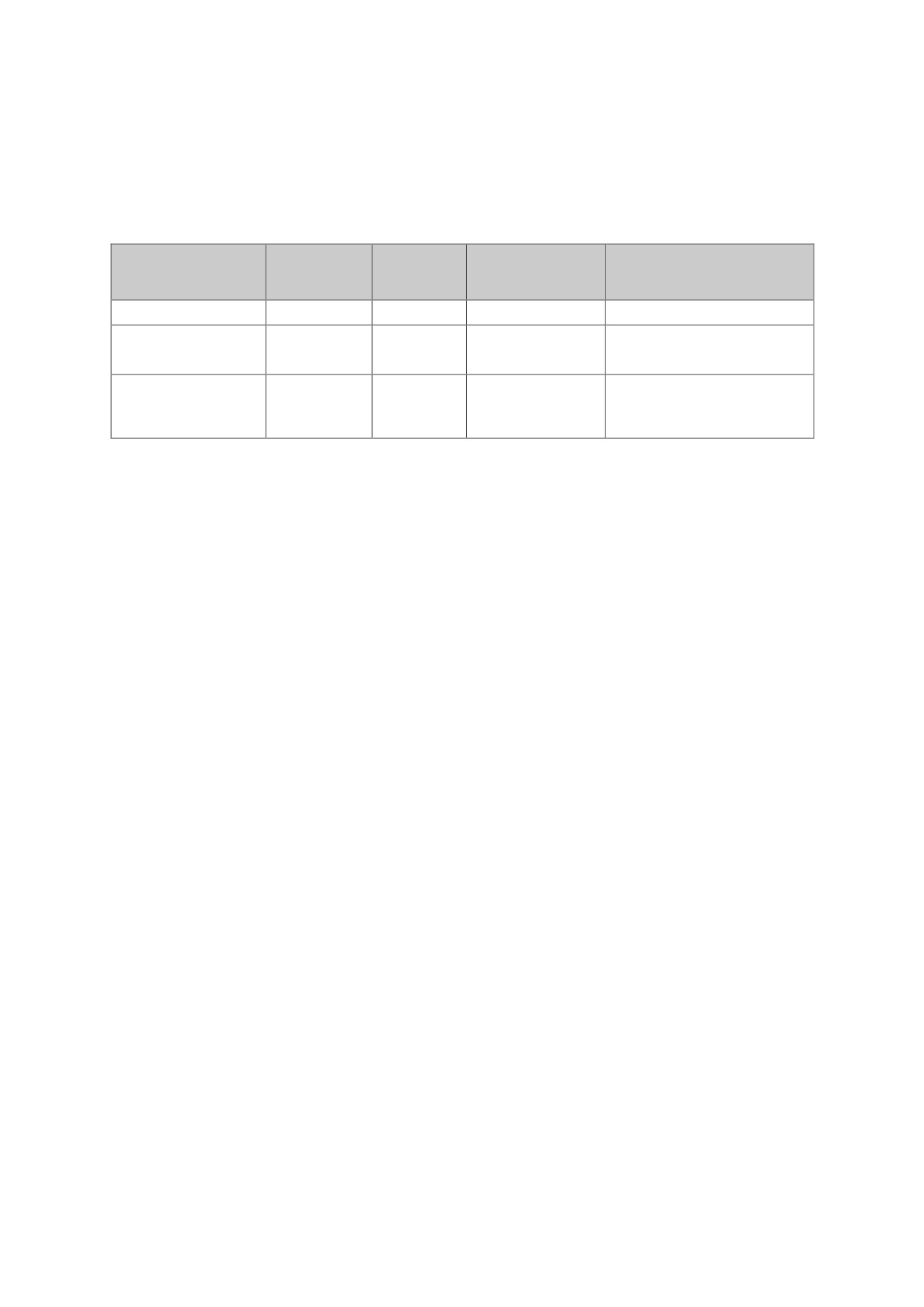
4.3.9 Code 0B (current signal selection)
Terminal X2 can be measured the current signal along with the change of load, the user can
according to the situation, there are four options, such as table 4.2
table 4.2
set value
0
1
2
3
Output current mA
0~20
0~20
4~20
4~20
calibration value
500%
150%
500%
150%
(1)
computational
500
150
D=25lx
D=7.5lx
D
(lx
4)
D
(lx
4)
16
16
formula %(2)
(1)the percentage of maximum load current output current corresponding to the number of
20 mA
(2)Ix measured current actual value (mA), D motor load current (%)
Formula interpretation:
1、D=25Ix: When the motor current is 0%, Ix=0; When the motor current is 100%, Ix=4mA, When
the motor current is 500%, Ix=20mA;
2、D=7.5Ix: When the motor current is 0%, Ix=0; When the motor current is 30%, Ix=4mA, When
the motor current is 150%, Ix=20mA;
500
D
(lx
4)
16
3、
:When the motor current is 0%, Ix=4mA; When the motor current is 500%,
Ix=20mA;
150
D
16
(lx
4)
4、
: When the motor current is 0%, Ix=4mA; When the motor current is 150%,
Ix=20mA;
4.3.10 Code 0C (current display)
0: The actual current value is displayed in the form of current value after starting
1: After the start of the display of the current display by a percentage, that is, 100% of the
current on behalf of the motor rated current rating
4.3.11 Code 0D (Programming delay) Code 0E (Programming output)
The programmed output of the starter (terminal 5,6) is controlled by the two programming codes,
see table 4.3
- 31 -

0E setting value
0
1
2
3
4
From Starting
From
Bypass
From Stop
Program timing
Delay
command
Starting
running
command
output time
status
moment
moment
status
moment
0E setting value
5
6
7
8
9
Start
Program output
Ready
running
fault status
+running
Starting status
indication status
status
status
status
Table 4.3
0: From Starting command moment: the programmable relay output from the moment of
starting command, and stop output after soft starter stops
1: From Starting moment: the programmable relay output from the moment of soft starter
starts, and stop output after soft starter stops
2: Bypass running status: the programmable relay output when bypass contactor running,
and stop output after bypass contactor stops
3: From Stop command moment: the programmable relay output when stop command
given to the starter, and stop output after soft starter stops fully
4: Delay status: the programmable relay output from starting delay ( Pa06) starts, and
and stop output after the delay time finish
5: Fault status: the programmable relay output when the starter has fault, and and stop
output after the soft starter reset
6: Starting and running: the programmable relay output in starting and running stage
7: Ready status: the programmable relay output when the starter is ready without alarm
before starting
8: starting status: the programmable relay output in starting stage
9: running status: the programmable relay output in running stage
If you set the item 0D is not 0, from the top of the table at the time as the starting point
according to the 0D set time to start the delay. Delay termination, the delay output contact
closure, otherwise if 0D is 0 closed immediately
The output of the reset (the contact is broken) at the time of the 0D is set up by the end of
time delay and ready for the state, flexible use of programmable relay output function, can
effectively simplify the peripheral control logic circuit
- 32 -
0E=49 programmable output function, set at this time 0D delay is invalid.
4.3.12Code 0F (phase loss protection)
0: phase loss function enable, the lack of any phase of the motor will stop running, and display
the fault status
1: phase loss function disable, will not stop even lacking phase
4.3.13 Code 10 (light load protection) and code 11 (light load rate)
Light load protection can be used to check the belt tripping accident, Pa10 set start light load
(0 is off), 1: beyond the set value to stop running starter and send out alarm signals through fault
relay, light load rate control with light load size, the definition of light load rate of kv:
Kv=Iv/Ie*100%
Ie: Rated current value, Iv: Average value of three-phase current
4.3.14 Code 12 (overvoltage protection)
Used to set the protection voltage value, if the input voltage is higher than the set value,
protection occurs
4.3.15 Code 13 (under voltage protection)
Used to set the protection voltage value, if the input voltage is lower than the set value,
protection occurs
4.3.16 Code 14 (Trip level)
In order to adapt to different applications, HHS series soft starter has five levels,
respectively, 0: primary, 1: light load, 2: standard, 3: heavy load, 4: senior, set by the function
code 13: as follows
Primary protection prohibits the external instant stop function, while retaining only the
overheating, short circuit and the input lacking phase of protection, suitable for the occasion
of the need for emergency, such as fire pumps
The light load, the standard, the heavy load protection levels have the complete
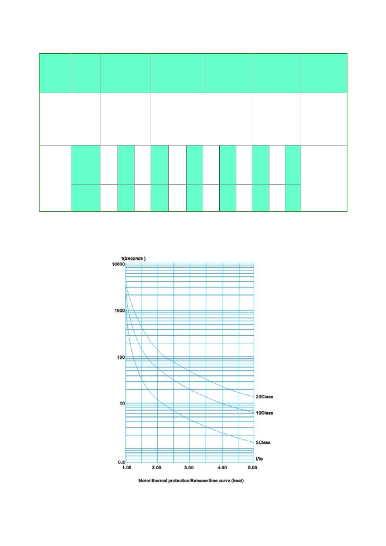
protection function, the difference is that the motor overload thermal protection time curve is
different .See table 4.4 and figure 4.5. for the thermal protection time of the motor
Advanced protection at the start of the protection of the standard is more stringent, other
protection parameters and standard protection settings
According to the function code 14 set different protection levels and thermal protection
time is as follows:
- 33 -
Table
4.4
0
14set
(prima
1(light load)
2(standard)
3(heavy load)
4(senior)
Description
ry)
According to
Overload
the
protectio
No
2level
10level
20level
10level
Iec6094742
n level
standard
Current
Run
multiple
3
4
5
3
4
5
3
4
5
3
4
5
The values in
overload
(I/Ie)
the table are
trip time
tripping
typical values
list
4.5
2.3
1.5
23
12
7.5
46
23
15
23
12
7.5
time(s)
Function code 14 set load adjustment rate is lower, the protection tripping sensitivity error
will increase. According to the motor thermal protection tripping time curve IEC60947-4-2
standards are as follows:
Fig. 4.5 curve of thermal protection tripping time (thermal state)
- 34 -
4.3.17 Code 15 (Self-starting)
After the start of the failure of the starter, it can be put into operation automatically by setting
the code 15 to
1 for the delay of about 6 seconds. If it is set to 0, it can only be restart after the
reset, and this function is only used in the two wire mode.
4.3.18 Code 16 (bus address)
Used to set the slave station address of the field bus, on the same station for each slave
station address is unique, set the principle of 7.2 field bus communication section
4.3.19 Code 17 (baud rate)
Select the communication rate for Modbus communication. Selectable ranges from 1200 to
19200, see also 7.1
4.3.20 Code 18(parity check)
When used for Modbus communication selection check, should be set according to the
requirements of the Master.
4.3.21 code 19 (load regulation rate)
In order to make the protection function and display parameters correct, the load regulation
rate should be reset when the user selects the soft starter rated parameters which do not match
the actual motor
Load regulation rate KT = ps/pr% PS actual motor power, PR soft starter power
For example: the user of the motor is 55kW, select the soft start power of 75kW, the code 19 set to
73%.
4.3.22 Code 1A (write protection)
When the function code 1A is set to 1, the parameter modification is locked, the user can not
modify the parameter value, the value must be changed to 0, the user can modify the parameters
4.3.23 Code 1B (language selection)
0: reserved
1: English
.4.3.24 Code 1C (Current coefficient)
60%~160%
100% is rated current of soft starter, if motor rated current is different. You can set this value to
- 35 -
make them same
.4.3.25 Code 1D (Restore factory settings)
0: Disable
1: Restore factory settings
.4.3.26 Code 1E (Bypass function)
0: Soft starter works in Bypass mode. After the motor starts, it switches to the grid power.
1. Soft starter works without bypass. After the motor starts, the soft starter provides power to the
motor.
- 36 -
4.4 How to program
4.4.1 Programming settings
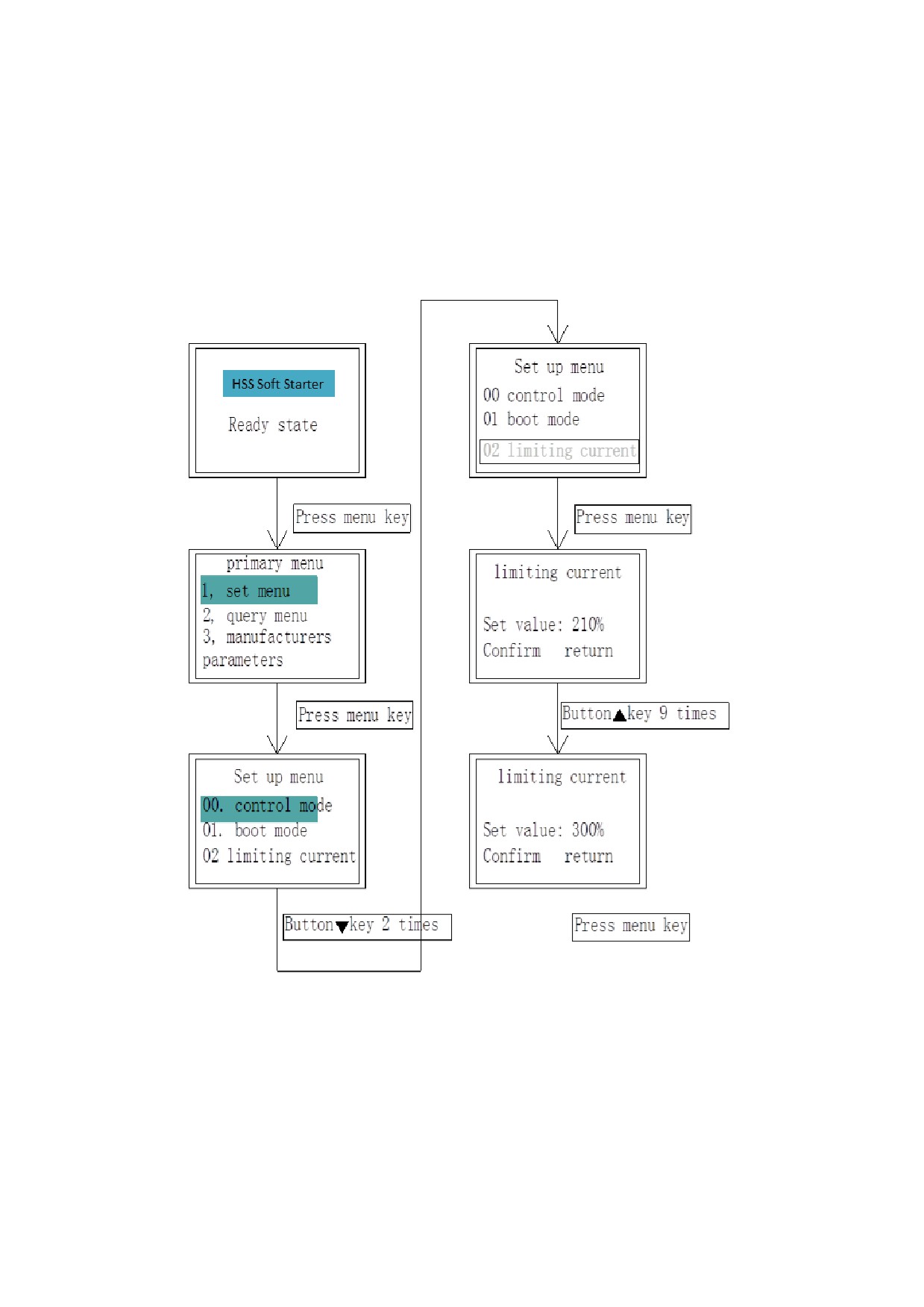
Setting the parameters of the soft starter correctly is the premise of the full implementation of
its performance, and the following is to modify the current limit value as an example to introduce
the parameter setting method of the HHS series soft starter panel
Note: once the data is written, it will remain in place until the next modification, not affected by
power failure.
- 37 -
Chapter 5 Electric operation
5.1 Test run
The main purpose of the test is to allow the user to confirm whether the direction of rotation of
the motor and the turning is normal
(1)To control the power supply, the panel should be displayed the company's LOGO for 2
seconds.
(2)The text area shows the ready state
(3)According to the situation of the motor load in the field, the parameters of the soft starter
can be adjusted reasonably, so that the motor can reach the optimal starting torque
(4)according to the run key at the same time to observe the direction of rotation of the
motor is in line with the requirements, if there is an exception can press the stop key to stop, such
as motor rotation can improve the starting voltage value, increase the starting torque
(5)The following methods can also be used to check whether the starter is normal, under
normal circumstances, the three light bulbs should be smooth
5.2 Running
z Refer to table 1 for starting parameters
z According to the panel RUN key, the starter starts to run, the motor is stable and no current
mutation shows that the parameter is set, the STOP key can be used to stop the machine
z After the failure, press 6.2 to find the cause of the failure
z Can not start, check the value of the code 00 and external control wiring: terminal STOP and
COM disconnect when the starter cannot start
z Press the STOP key or close the external control terminal RET to reset the fault state
z When the starting time for a drag two parking time must be set to 0, such as the need for
external control terminals RUN and STOP start operation, please set the code 00 to 1or 3。
- 38 -
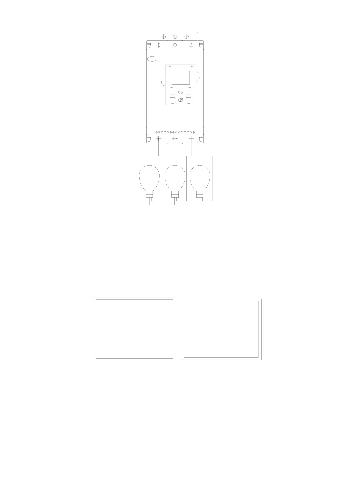
MENU
EXIT
RUN
STOP
Light Power
Rating>200W
You can also check whether the starter is normal by using the figure above. Under normal
circumstances, the three bulbs should be steadily lit up
5.3 Running time data display
The average value of three-phase current when running is shown in figure 5.2:
Monitoring parameters
Current:
20.0A
Voltage: 380V
Current: 9.0A
running
Temperature:22℃
Figure 5.2 Figure 5.3
The operation can also press the MENU key to enter the menu in the main menu, select the
monitoring parameters, you can view the voltage, current and SCR temperature, as shown in
Figure 5.3
- 39 -
Chapter 6 Fault display
HHS soft starter has protection function; any fault will be shut down, and display and memory
fault code. Only with the stop key or the external control reset terminal remove the fault state to
reboot. (which can be self starting function, in the two line method to start)
6.1 Panel display
fault
Code: ER03
Phenomenon:
input missing
phase
6.2 Fault code table
Fault
fault code
Causes and troubleshooting
phenomenon
Instantaneous
stop broken
ER01
Instantaneous stop terminal EMS open circuit to COM
circuit
Start timeout
ER02
Current limiting value is too low or too heavy
Check whether the input circuit and the bypass contactor is
Input phase
ER03
stuck in the closed position and whether the SCR is open or
defect
not
Output lacking
ER04
Check motor wiring and SCR damage
phase
Parameter error
ER05
Restart or re enter the Default value
Starting over
Whether the load is too heavy or the motor power does not
ER06
current
match with the soft starter
Operating
ER07
Check whether the load is too heavy
overload
- 40 -
Running light
ER08
Check if the load is too light
load
Starting too often or motor power does not match the soft
SCR overload
ER09
starter
Load short
Check whether the load or thyristor is short circuited or the
ER10
circuit
load is too large
485 communication failure, check the external connection
Bus fault
ER11
terminal
Low Voltage
ER12
Check the input power supply voltage or set the item 12
Voltage high
ER13
Check the input power supply voltage or set the item 11
When the control mode is 3 or 4, the external control terminal
wiring error
ER14
is in the open state
Communication
ER15
Keyboard communication failure
failure
6.3 Fault memory
Enter the query menu fault records can view the fault, the starter can remember 10 faults for
the user to analyze, the user can clear the stored fault
6.3.1 Display memory failure
z The number 1 represents the most recent failure, and the new fault will wash away the
previous memory
z You can view the▲▼ key to see all of the fault records.
Fault record
number:
1
ER03:Input
1osting phase
Clear return
- 41 -
6.3.2 Fault clearing
After the failure of the query, the boot is best to clear the previous fault memory, the method is
in the case of the fault query, press the menu key can be cleared
fault recording
number:
1
Clear return
- 42 -
Chapter 7 Communication protocol
When selecting bus control, the function code 00 must be set to 2,4,5 to activate the bus
7.1 HHS Modbus Protocol Part
This section describes how to use Modbus communication to control the various operations of
HHS
7.1.1 Overview of Modbus
Modbus is a serial asynchronous communication protocol. The physical interface for
rs485.modbus is designed for Modicon PLC, with PLC structure characteristics of the. Modbus in
the network control, HHS can be likened to a soft starter PLC to read and write. HHS will start stop
control, state information (fault current, etc.) to keep register area and function parameter mapping
(4xxx). Through the use of PLC to read and write control of the master station.
Table 7.1
Register address
action code
Register function specification
40001
06
control word
40002
03
status word
40003
03
Average current (%)
40004
03
Fault code
40257-40281
03&06
Soft starter function code
(1)In addition to the above listed registers are illegal and cannot be read or written. Otherwise,
HHS will report an exception code to the controller
(2) All data addresses are based on the reference of 0, i.e., the address of the coil relay 40001
is 000040257 () of 0100
7.1.2 Exception code
HHS supports the standard MODBUS exception code (see table 7.2)
Table
7.2
exception code
code
name
Description
Function code cannot be executed, THS1-8000 does not
01
Illegal function
support
Invalid data
The received data address cannot be executed, the
02
address
address overflow
03
Invalid data value
Received data cannot be executed
- 43 -
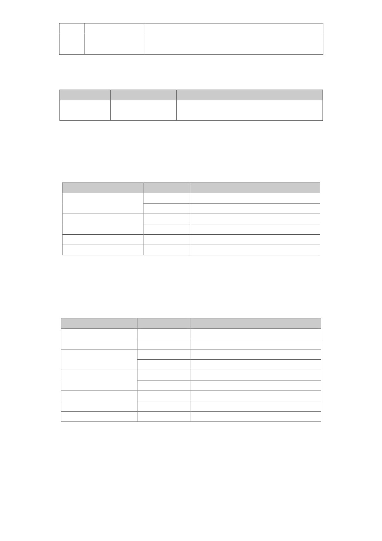
1.Parameter out of range
2.Parameter cannot be modified
3.Parameters cannot be modified at run time
HHS only supports the function code listed in Table 3. If you use the other code, you will give
the exception code 1, MODBUS
code
03
06
Function
Read storage
Preset single register
description
register
Code 03 reads only a single word (word)
7.1.3 Register declaration
z
40001 command register
bit
value
description
1
Starter starting
0
0
hold mode
1
Starter stop
1
0
hold mode
2
0-1
Reset the starter
3-15
0
Unused
For example: from the soft starter station address 02, the controller sends out 020600000001,
such as command normal execution, return code 20600000001 to check whether the normal
starting starter status register. If a fault exists, should be given 020600000004 reduction.
z Register address 40002 status register
The status register reflects the state of the soft starter, represented by a bit
Bit
value
description
1
Starting state
0
0
Parking state
1
running state
1
0
Parking state
1
Soft stop state
2
0
Parking state
1
fault condition
3
0
normal condition
4-15
Unused
Example: read status code 02 03 00 01 00 01
If the starter is starting, the return code 02 03 02 00 01
Returns 02 03 02 00 08 if the starter fails and the fault type can be read in accordance with
4
z
40003 Average current (sixteen)
This value indicates the average value of the three-phase actual current of the HHS,
- 44 -

according to the setting of the function code 0C, or the current percentage or the actual current
value
Example: read current size
Send Code 02 03 00 02 00 01
If the current is 235A, return 02 03 02 00 EB
z
40004 Fault code (sixteen)
When the status register 40002 bit 3 is 1, the HHS is represented in a fault state. The fault
code is consistent with the 7.2
For example: send code 02 03 00 03 00 01
if returns 02 03 02 00 04, the current input is missing, description current input losing phase (fault
code 03)
z Soft starter function parameter register 40xxx
Among them (xxx-1) with sixteen hexadecimal as 1YY, YY and table 3 - 1 code value is
corresponding; for example, with the function code 08 (sudden Jump voltage) corresponding to
these functions can be read and write code, the following are examples of its use:
Example 1 read function code 02 (current limit value) size
Controller gives 02 03 01 02 00 01
Returns the value of the 02 function code read. 02 03 02 01 5E indicates the current limit
value is 350%
Example 2 read function code 13 (protection level)
Send code 02 03 01 13 00 01, return to 02 03 02 00 03, read the protection level of 3
Example 3 rewrite the soft starter function code 02 (limiting current) to 250%
The host sends the code 02 06 01 02 00 FA, HHS returns the code to 02 06 01 02 00 FA; if
returns the 02 86 03 to indicate cannot write, possibly the starter is running
Example 4 the function code 09 is stored at a value of about 10 times, such as the read function
code number (Jump time)
Send code 02 03 01 09 00 01, return of 02 03 02 00 03, read the Jump time is 3, the actual
value of 0.3s. is the contrary, write Jump time 0.3s, just send the 02 06 01 09 00 03
7.1.4 Connection and setting
The following set of functional code and communication related to the use of the panel must be set
HHS function code
content
set value
16
Bus address
1-247
17
Baud rate
1200~19200bps
even-odd
18
0: NO
1: odd
2: even
check
- 45 -
7.1.5 Precautions for use
(1)The address of the HHS (function code 16) must be in accordance with the control address
of the controller; the baud rate (function code 17); even-odd check (function code 18) is the
same as the controller; the parameter must be reset to power up
(2)If not receiving the response data, the parameters should be set to check the above, the 485
terminal connection is correct, the CRC effect is correct.
(3)More than one HHS communication, should be at the end of the last AB on both ends of the
120 ohm resistance
(4)In connection with other MODBUS devices, as shown in Figure 7-1
1
GND
GND
2
A
A
3
NC
B
4
B
5
5V
Shielded
Other MODBUS
enclosure
图 7.1
7.1.6 Establishment of communication network
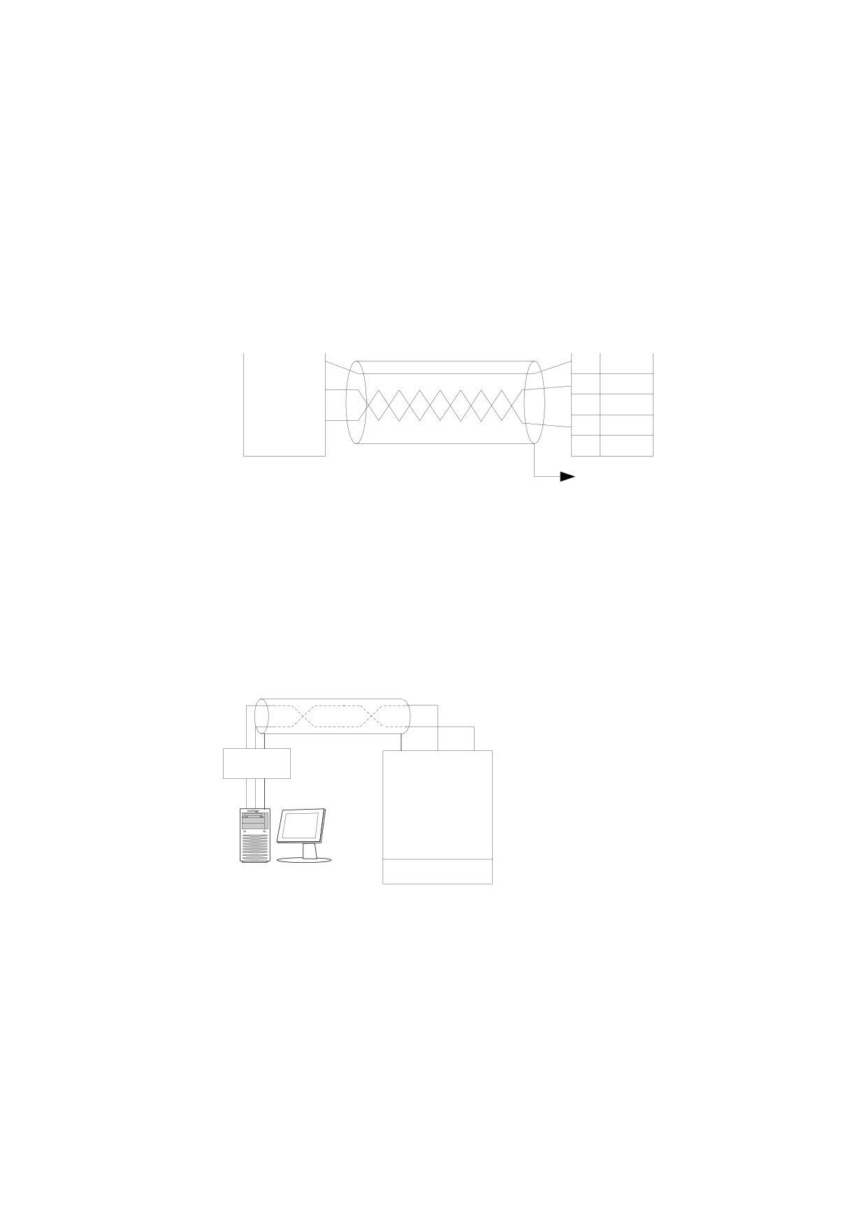
(1)Connection a soft start and a computer connection
Shielded twisted pair
converter
RS232-485
GND
485+
485-
RS232 cable
GND
up to 15
meters
computer
Station
0
Figure 7.2 the connection between a soft start and a computer
(2)Multiple soft start and computer connections
- 46 -
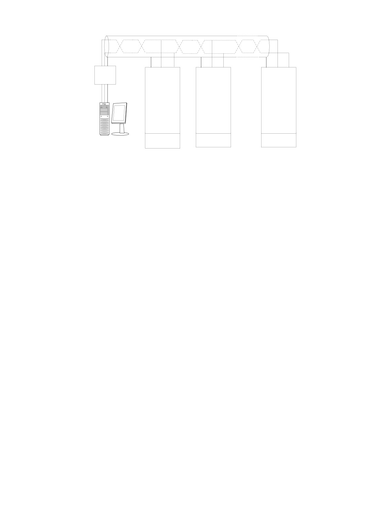
Shielded twisted pair
converter
RS232-485
GND 485+ 485-
GND 485+ 485-
GND 485+ 485-
RS232 cable
GND
up to 15
meters
· · · · · ·
computer
Station 0
Station 1
Station n
Figure 7.3 the connection between a soft start and a computer
- 47 -
Chapter 8 HHS use precautions and routine
maintenance
8.1 Precautions for use
z
Prevent electric shock
The input power of HHS soft starter, when the load or open phase, even in the stopped
state, its output will still have a very high voltage induction. The output end of the no contact of
the soft starter, otherwise there will be the risk of electric shock.
HHS soft starter control circuit board with 380V voltage, the electric shock risk when
debugging
z
Induction voltage
Induction voltage soft starter HHS output at no-load is normal phenomenon, does not
affect the use of induction voltage by leakage of SCR (silicon controlled rectifier, GTR, IGBT
and other solid-state semiconductor devices have different degrees of leakage) exchange
pathway and dv/dt resistance capacitance filter loop. Voltage meter to zero measurement,
about 100~220v (related to the internal resistance of the voltmeter). The induction voltage of
load capacity is very small, disappeared in the output connection after load.
z
Compensating capacitor
The reactive power compensation capacitor used to improve the power factor must be
connected to the input of the HHS soft starter, not to be connected to the output, otherwise it
will damage the SCR power device in the soft starter
z
Meg-ohmmeter
The insulation resistance between the input and output of the HHS soft starter shall not
be measured with the Meg-ohmmeter, otherwise the thyristor and the control board of the soft
starter may be damaged due to excessive pressure
HHS can be used to measure the soft phase of the soft starter and relatively insulated,
but should be in advance with three short lines will be the three-phase input and output
shorted, and unplug all the plugs on the control panel
Measurement of motor insulation, should also follow the above principles
z
Input and output
Do not connect the input and output terminals of the main circuit of the HHS soft starter,
otherwise it will result in the unintended action of the soft starter, which may damage the soft
starter and the motor
- 48 -
z Bypass phase sequence
When the bypass contactor is used, the phase sequence of the starting circuit should be
consistent with the phase sequence of the bypass circuit. Otherwise, the bypass switch will
cause an interphase short circuit, which will cause the air circuit breaker to trip or even
damage the equipment
z Low voltage level
Terminals 7,8,9,10,11 shall not be connected to other external power sources on the
terminals, or they will damage the internal circuit of the soft starter
z Soft starter voltage rating
Terminals
13,14 use external AC380V operating voltage, not on these terminals
connected to other voltage rating power supply, otherwise it will damage the internal circuit of
the soft starter
8.2 Daily maintenance of soft starter
z Dust content
If there is too much dust, the insulation level of the soft starter will be reduced, and the soft
starter may not work properly
a.primary circuit creepage, pulling arc, hazard equipment;
b.two circuit leakage, short circuit, control failure;
c.heat sink thermal resistance, SCR temperature rise
z Cleaning dust
a.clean and dry brush gently brush the dust;
b.use compressed air to blow away the dust
z Dew condensation
If frosting, the insulation level of the soft starter will be reduced, and the soft starter may not
work properly
a.primary circuit creepage, pulling arc, hazard equipment;
b.two circuit leakage, short circuit, control failure;
c.aggravates seat corrosion of metal parts
z Drying up
a.With electric or electric stove drying;
b.Wwet distribution room
- 49 -
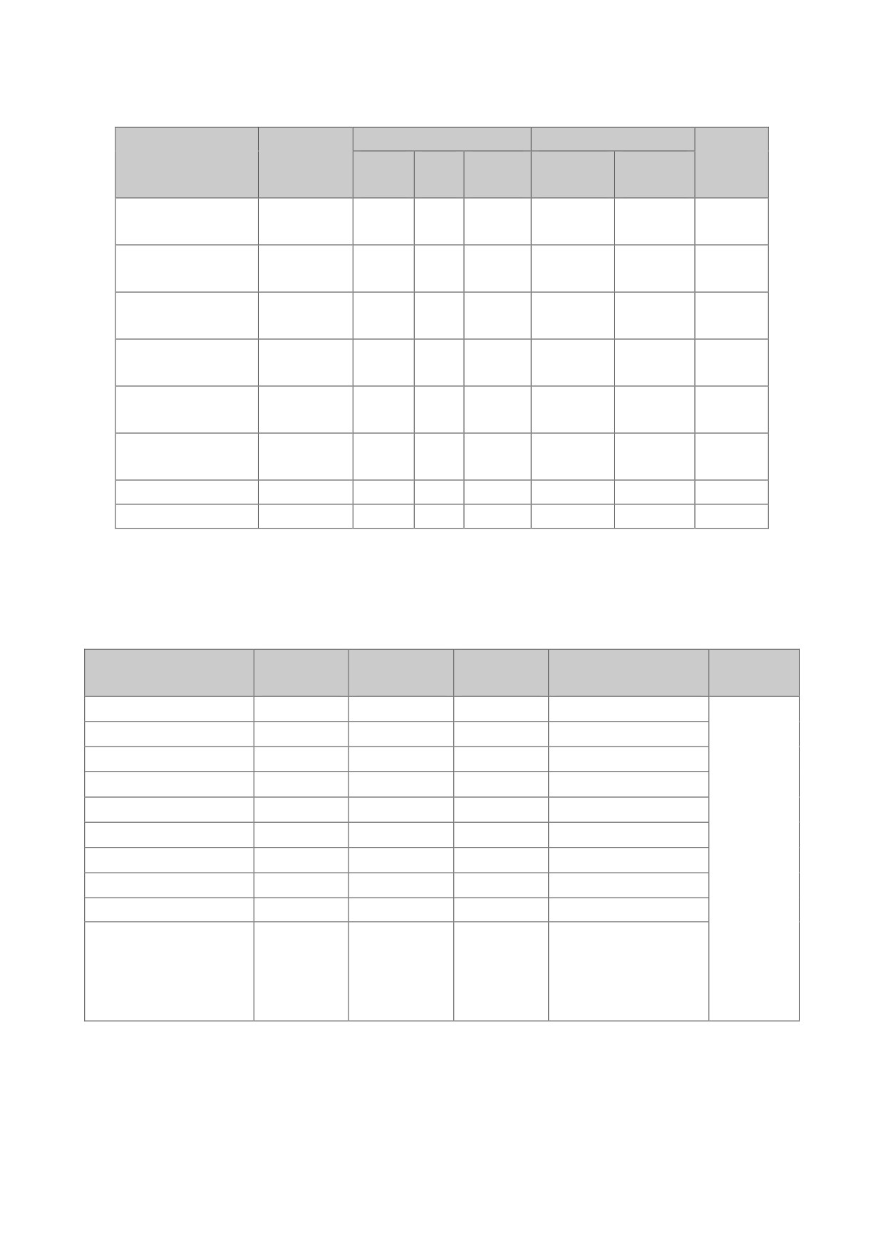
Schedule 1, Application
Starting mode
Numerical setting
Rise
Mechanical type
Load type
voltag
curr
over
voltage
current
time
e
ent
loading
(%)
(%)
standard
centrifugal pump
•
250
5
termination
Biased
draught fan
•
•
400
40
load
Compressor
standard
•
300
10
(piston type)
termination
Compressor
standard
•
30
20
(centrifugal)
termination
standard
transport
•
250
10
termination
standard
agitator
•
•
350
5
termination
ball crusher
Heavy load
•
•
70
400
50
breaker
Heavy load
•
60
45
Schedule 2, Peripheral parts specification parameters
HHS series soft starter (5.5kw-75kw)
Power rating
Rated current
SCPD
Primary line
Model
Note
(kw)
(A)
specification
specification
HHS-5R5-B-4T-4-2
5.5
11
20
2.5mm2cable conductor
55kW and
HHS-7R5-B-4T-4-2
7.5
15
30
4mm2cable conductor
below with
the cable
HHS-011-B-4T-4-2
11
23
50
6mm2cable conductor
lead out
HHS-015-B-4T-4-2
15
30
80
10mm2cable conductor
wiring, the
HHS-018-B-4T-4-2
18.5
37
80
10mm2cable conductor
way into the
HHS-022-B-4T-4-2
22
43
80
16mm2cable conductor
three out of
HHS-030-B-4T-4-2
30
60
100
25mm2cable conductor
six. Rated
HHS-037-B-4T-4-2
37
75
150
35mm2cable conductor
power rated
HHS-045-B-4T-4-2
45
90
200
35mm2cable conductor
current is
the
maximum
HHS-055-B-4T-4-2
55
110
200
35mm2cable conductor
value of soft
starter。
Note: the specifications of peripheral accessories list for reference
- 50 -
HHS series soft starter (75kw-320kw)
Rated power
Rated current
SCPD
Primary line
Model
Note
(kw)
(A)
specification(A)
specification
300
35mm2cable
HHS-075-B-4T-4-2
75
150
conductor
320
30×3mm2Coppe
75kW and
HHS-090-B-4T-4-2
90
180
r bar
above is
480
30×3mm2Coppe
used to
HHS-115-B-4T-4-2
115
230
r bar
lead the
600
30×4mm2Coppe
cable
HHS-132-B-4T-4-2
132
260
r bar
wiring, six
600
30×4mm2Coppe
to the way
HHS-160-B-4T-4-2
160
320
r bar
out of the
700
40×4mm2Coppe
three.
HHS-185-B-4T-4-2
185
370
r bar
Rated
700
40×4mm2Coppe
power rated
HHS-200-B-4T-4-2
200
400
r bar
current is
800
40×5mm2Coppe
the
HHS-250-B-4T-4-2
250
500
r bar
maximum
1000
40×5mm2Coppe
value of soft
HHS-280-B-4T-4-2
280
560
r bar
starter
1000
40×5mm2Coppe
HHS-320-B-4T-4-2
320
640
r bar
1000
40×5mm2Coppe
HHS-355-B-4T-4-2
355
710
r bar
Note: the specifications of peripheral accessories list for reference
- 51 -
HHS series soft starter (400kw~600kw)
Rated power
Rated current
SCPD
Primary line
Model
Note
(kw)
(A)
specification
specification
50×6mm2Copper
400KW
HHS-400-B-4T-4-2
400
800
/
bar
and above
is used to
50×6mm2Copper
HHS-450-B-4T-4-2
450
900
/
bar
lead the
cable
60×8mm2Copper
HHS-500-B-4T-4-2
500
1000
/
wiring, six
bar
to the way
out of the
three.
Rated
power
60×8mm2Copper
rated
HHS-600-B-4T-4-2
600
1200
/
bar
current is
the
maximum
value of
soft starter
Note: the specifications of peripheral accessories list for reference.
- 52 -
Quality Warranty
The warranty of soft starter is as follows:
(1) Warranty period under normal conditions.
We provide guarantees for repair and replacement in 3 months from the date of use.
We provide guarantee for repair in 12 months from the date of use or 18 months from the date of
ex-factory.
(2) The purchaser enjoys life-long paid service whenever and wherever he uses a motor soft starter made in
our company.
(3) Service in the following cases, even within the warranty period, shall be charged to the purchaser:
Problems caused by mal-operation in violation of this manual, or caused by unauthorized repair or
renovation.
Problems caused by improper use of soft starter that is off standard and requirement;
Malfunction or damage caused by improper transit or storage after purchase;
Induced failure or aging of the device due to poor ambient;
Malfunction or damage caused by fire, flood, thunder, earthquake, abnormal voltage or other natural
disasters;
Unidentifiable nameplate, mark and ORD number due to intentional spoilage;
Delayed or unsatisfied payment in violation of purchase appointment;
Fail to give an objective description on the use of installation, wiring, operation, maintenance or else;
(4) Defective products should be sent to us for repair, replacement and return, which can be proceeded only
after verifying the burden of liability.
(5) In case there is any quality problem or accident, we merely promise to bear the above-mentioned
responsibilities. If a user needs more guarantees for liabilities, please assure on the insurance company
voluntarily.
Warranty Bill
User company name:
Website:
Address:
Tel:
Purchase date:
Fax:
Product model:
Contact person:
Products’ code:
Equipment:
Matched Motor
Remark:
- 53 -