HV10 Series Frequency Inverter. User Manual (Edition: V6.0)
Content
I. Technical indicators and specifications of products
2
II. Inverter Installation and Wiring
4
2.1 Matters needing attention for Installation
4
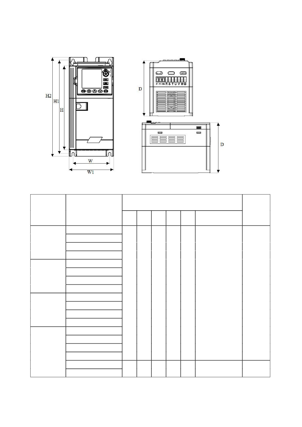
2.2 Outline drawing
5
a. Overall dimensions of keypad base
5
b. Overall dimensions of the whole machine
6
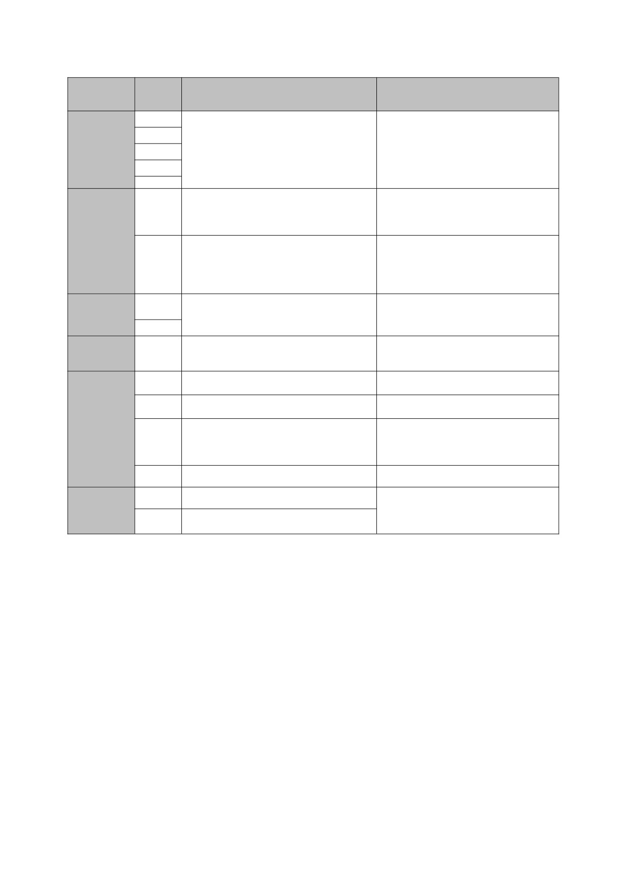
2.3 Basic operation wiring
7
2.4 terminal for controlling loop
7
2.5 Matters needing attention for Wiring
9
III Communication protocol
10
1.RTU mode and format
10
2.Description of reading and writing function code:
10
3.Register address
10
4.Description of parameter address of communication protocol:
10
5. 03H Reading function mode:
12
6. 06H write function mode
13
IV. Exceptions and Handling
15
V. Parameters instructions
16
VI. Parameter description
31
00 group-basic operating parameters
31
01 group-auxiliary operating parameters
36
02 group-analog and digital input and output parameters
42
03 group -PID parameters
49
04 group -advanced functions parameters
53
05 group- Protective Function parameters
56
06 group: communication parameters
59
07 group- supplementary Function parameters
61
08 group-manage and display parameters
63
Appendix: Braking resistor selection
66
Warranty agreement
666
1
I. Technical indicators and specifications of products
Rated
voltage
,
Three-phase (G3/G4 series) 380V-480V, 50/60HZ
Frequency
Single&Three-phase (G1-2/G2 series)
220 V: 50/60 Hz
Single -phase (G1-1 series) 120 V: 50/60 Hz
Input
Allowable range of
Three-phase (G3 series) : AC 380~440 (-15%~+10%)
voltage variation
Three-phase (G4 series) : AC 460~480 (-15%~+10%)
Single&Three-phase (G11-2/G2 series) : AC220V±15%
Single -phase (G1-1 series) :AC120 V±15%
Voltage
G1-1 series :0~220V;G1-2/G2 series; 0~220V, G3 series; 0~440 V, G4 series; 0~480 V
Frequency
0~999.9HZ
Output
Overload capacity
110% long-term; 150% 1 minute; 180% 5 seconds
Control mode
V/F control, Vector control
Frequency setting
Analog input
0.1% of the maximum output frequency
resolution
Digital settings
0.1HZ
Analog input
Within 0.2% of the maximum output frequency
Frequency accuracy
Digital input
Within 0.01% of the set output frequency
V/F curve (voltage
Three ways: the first is linear torque characteristic curve, the second is square
frequency
torque characteristic curve, and the third is user-set V/F curve
characteristic)
Manual setting: 0.0 ~ 30.0% of rated output
Torque boost
Automatic lifting: automatically determine the boost torque according to the
V/F control
output current and motor parameters
Whether in acceleration, deceleration or stable operation, the motor stator
Automatic current
current and voltage can be automatically detected, which can be suppressed
and voltage
Control
within the allowable range according to the unique algorithm to minimize the
limiting
characteri
possibility of system fault tripping
stic
voltage frequency
Automatically adjust output voltage-frequency ratio according to motor
characteristic
parameters and unique algorithm
Starting torque:
Torque
Sensorless vector
100% rated torque at 0.5Hz (V/F control)
characteristic
control
150% rated torque at 0.5Hz (Vector control)
Current and
Full-range current closed-loop control, completely avoiding current impact,
voltage
with perfect overcurrent and overvoltage suppression function
suppression
Undervoltage
Especially for users with low grid voltage and frequent fluctuation of grid voltage, the system can
suppression during
maintain the longest possible operation time according to the unique algorithm and residual energy
operation
allocation strategy even in the range below the allowable voltage
Multi-stage speed
7-stage programmable multi-stage speed control and multiple operation modes are optional.
operation
PID control
Built-in PID controller (preset frequency). Standard configuration RS485 communication function,
RS485 communication
multiple communication protocols can be selected, with linkage synchronous control function
DC voltage 0 ~ 10 V, DC current 0 ~ 20 mA (upper and lower limits are
Analog input
optional)
Frequency setting
Operation panel setting, RS485 interface setting, UP/DW terminal setting, and
Digital input
various combination settings with analog input can also be made.
Typical
1 OC output and 1 relay output (TA,TC), with up to 17 functions
Digital output
function
Output signal
1 AO, the output range can be flexibly set between 0 ~ 20mA or 0 ~ 10V,
Analog output
which can realize the output such as set frequency and output frequency.etc
Automatic voltage
According to the needs, three modes can be selected: dynamic voltage stabilization, static voltage
stabilizing operation
stabilization and non-voltage stabilization, so as to obtain the most stable operation effect
Acceleration /
0.1S~999.9min can be set continuously
deceleration time
setting
2
Energy
Energy consumption braking starting voltage, return difference voltage and energy consumption
consumption
braking rate can be continuously adjusted
braking
Brake
Starting frequency of DC braking during stop: 0.00 ~ [00.05] upper limit frequency
DC brake
Braking time: 0.0 ~ 30.0s; Braking current: 0.0% ~ 50.0% of rated voltage of motor
The carrier frequency is continuously adjustable from 2.0 kHz to 20.0 kHz to minimize the noise of
Low noise operation
the motor
Counter
One internal counter is convenient for system integration
Upper and lower limit frequency setting, frequency jump operation, reverse operation limit, slip
Operating function
frequency compensation, RS485 communication, frequency increment and decrement control, fault
self-recovery operation, etc
Output frequency, output current, output voltage, motor speed, set frequency, module temperature,
Running status
PID setting, PID feedback , analog input and output, etc
Display
Record a number of operating parameters such as output frequency, set frequency, output current,
Alarm content
output voltage, DC voltage and module temperature during the latest fault
Overcurrent, overvoltage, undervoltage, module failure, electronic thermal relay, overheating, short
Protection function
circuit, internal memory failure, etc.
Ambient temperature
-10℃ ~ +40℃ (when the ambient temperature is 40℃ ~ 50℃, please use it at a reduced level)
Ambient humidity
5% ~ 95% RH, no water condensation
Environm
Surrounding
Indoor (no direct sunlight, corrosion, flammable gas, oil mist, dust, etc.)
ent
environment
Altitude
Derating for use above 1000 meters, every 1000 meters up derating 10%
Structure
Protection grade
IP20
Cooling mode
Air-cooled with fan control
3
II. Inverter Installation and Wiring
2.1 Matters needing attention for Installation
Danger
1.
Before wiring, please confirm that the input power supply has been cut off.
Danger of electric shock and fire.
2.
Ask electrical engineering professionals for wiring operations.
Danger of electric shock and fire.
3.
The grounding terminal must be grounded reliably.
Danger of electric shock and fire.
4.
After the emergency stop terminal is connected, check whether its action is effective.
There is a danger of injury. (the wiring responsibility shall be borne by the user)
5.
Do not touch the output terminal directly. The output terminal of the frequency inverter is
directly connected with the motor. Do not short circuit between output terminals.
Danger of electric shock and short circuit.
6.
Before power-on, be sure to install the terminal cover. When removing the cover, always
disconnect the power supply first.
There is danger of electric shock!
7.
Cut off the power supply, and wait for 5 to 8 minutes for the remaining power in the machine to
be basically discharged before carrying out inspection and maintenance.
Danger of residual voltage on electrolytic capacitor.
8.
Do not carry out inspection and maintenance for non-professional technicians.
There is danger of electric shock!
Attention
1. Please confirm whether the power supply voltage of incoming line is consistent with the rated
input voltage of frequency inverter.
There is danger of injury and fire.
2. Please connect the braking resistor or braking unit according to the wiring diagram.
Danger of fire.
3. It is best to use a screwdriver and wrench with specified torque to fasten the terminals.
Danger of fire.
4. Do not connect the input power cord to the output U, V and W terminals.
Voltage applied to the output terminal will cause internal damage of the frequency inverter
5. Do not remove the front panel cover, only the terminal cover needs to be removed when
wiring.
May cause internal damage to the inverter.
4
2.2 Outline drawing
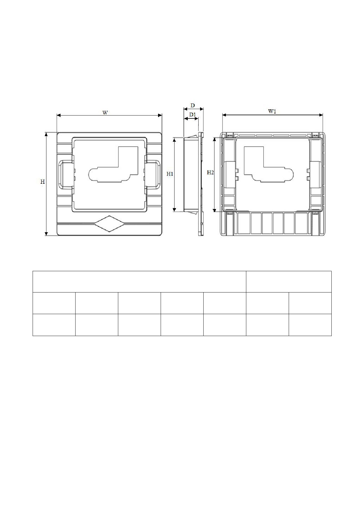
a. Overall dimensions of keypad base
Right side
Side face
Back side
Opening size of keypad base
keypad thickness
W
W1
H
H1
H2
D
D1
105mm
100mm
83mm
59.5mm
59.5mm
19.54mm
14.64mm
5
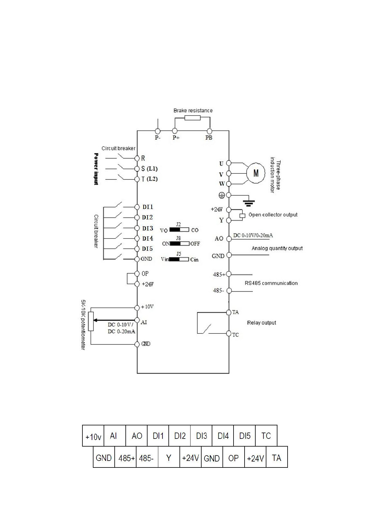
b. Overall dimensions of the whole machine
Outline construction and installation dimension
Voltage
Weight
(mm)
Model
level
W
H1
D
W1
H2
Mounting hole(d)
(kg)
HV10−R40G1-1
HV10−R75G1-1
1PH 120V
HV10-1R5G1-1
HV10−2R2G1-1
HV10−R40G1-2
HV10−R75G1-2
1PH 220V
HV10-1R5G1-2
HV10−2R2G1-2
60
160
134
78
170
4
0.9
HV10−R40G2
HV10−R75G2
3PH 220V
HV10−1R5G2
HV10-2G2G2
HV10−R40G3
HV10−R75G3
3PH
HV10−1R5G3
380V/460V
HV10−2R2G3
HV10−004G3
78
200
152
95
212
4
1.3
HV10−5R5G3
6
2.3 Basic operation wiring
The wiring part of the frequency inverter is divided into the main circuit and the control circuit. The user can open
the cover of the output/input terminal, and the main circuit terminal and the control circuit terminal can be seen at this
time. The user must connect correctly according to the wiring circuit shown below.
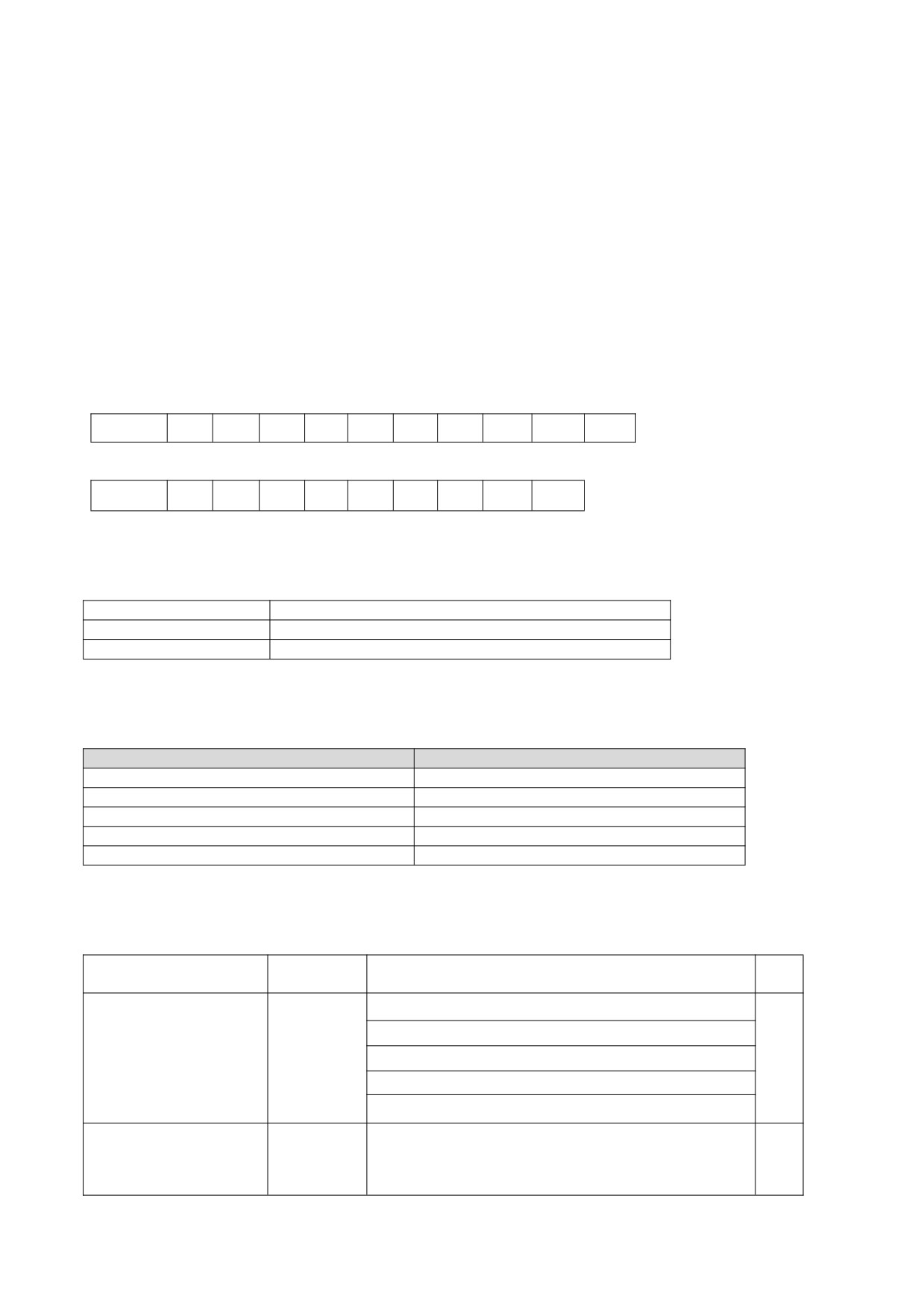
2.4 terminal for controlling loop
7
Terminal
Function Description
Specification
DI1
DI2
The factory default is valid when DI (DI1, DI2, DI3,
Multifunctional
DI3
DI4, DI5) and GND are short-circuited when OP and
INPUT, 24V level signal, high level active, 5mA.
DI
24V are short-circuited.
DI4
DI5
AI voltage/current input, voltage and current are
Input voltage range: 0 ~ 10V (input impedance:
selected by jumper J5, the factory default is voltage,
100KΩ),
AI
if you want current, just adjust the jumper cap to the
input current range: 0~20mA (input impedance:
Multifunctional
C2 position. (Reference ground: GND)
500Ω).
AO provides analog voltage/current output, the
AI/AO
current is selected by jumper J2, the factory default
AO
output voltage, if you want to output current, just
0~10V DC voltage/0~20mA current.
jump the jumper cap to the C position. (Reference
ground: GND)
TA-TC is NO。
TA
It can be defined as a multi-function relay output
Relay output
Contact rating:
terminal.
TC
250VAC/2A(COSФ=1),30VDC/1A.
It can be defined as a multifunctional collector output
1. Switching capacity: 50mA/30V
OC output
Y
terminal, which can be used as a high-speed pulse
2. Output frequency range: 0~50kHz
output.
The common power supply for the circuit of the
+24V
Maximum output current 200mA
digital signal input terminal
The circuit common power supply for analog input
+10V
Maximum output current 20mA
and output terminals
The factory default is connected to
+24V. When
Power supply
using external signals to drive DI1 ~ DI5, OP needs
OP
External power supply input terminal
to be connected to the external power supply and
disconnected from the +24V power supply terminal
GND
Analog signal and +10V power reference ground
Digital GND
Standard RS485 communication interface, not
485+
RS485+
isolated from GND, please use twisted pair or
Communication
shielded wire.
485-
RS485-
Jumper J8 is for RS485 terminal resistor.
8
2.5 Matters needing attention for Wiring
1
When replacing the motor, you must cut off the input power of the inverter.
2
When the frequency inverter stops outputting, the motor can be switched or the power frequency can be switched.
3
In order to minimize the influence of electromagnetic interference, when the electromagnetic contactors and relays
used are close to the frequency inverter, the surge absorption device should be considered.
4
Do not connect the AC input power to the output terminals U, V and W of the frequency inverter.
5
The external control line of the frequency inverter needs to be isolated or shielded.
6
In addition to shielding, the input command signal connection should be routed separately, preferably away from the
main circuit connection.
7
When the carrier frequency is less than 4KHz, the maximum distance between the inverter and the motor should be
within 50 meters. When the carrier frequency is greater than 4KHz, this distance should be appropriately reduced.
This connection is best laid in a metal pipe.
8
When the inverter is equipped with peripheral equipment (filter, reactor, etc.), the insulation resistance to the ground
should be measured with a 1000 volt megohmmeter to ensure that it is not lower than 4 megohms.
9
Phase-in capacitors or resistance-capacitance absorption devices cannot be installed at the U, V and W output
terminals of the frequency inverter.
10 If the frequency inverter needs to be started frequently, dont turn off the power supply. You must use the GND/RUN
of the control terminal to start and stop, so as not to damage the rectifier bridge.
1
In order to prevent accidents, the grounding terminal G must be grounded reliably (the grounding impedance should
be below 100Ω), otherwise there will be leakage.
12 When wiring the main circuit, please choose the wire diameter specification according to the relevant provisions of
the national electrical regulations.
9
III Communication protocol
1. RTU mode and format
When the controller communicates on Modbus in RTU mode, every 8-bit byte in the information is divided into two
4-bit hexadecimal characters. The main advantage of this mode is that the density of characters transmitted by it is
higher than that of ASCII mode at the same baud rate, and each information must be continuously transmitted.
(1) The format of each byte in 1)RTU mode
Coding system: 8-bit binary, hexadecimal 0-9, A-F.
Data bit: 1-bit start bit, 8-bit data (lower bit first sent), 1-bit stop bit, and optional parity bit. (Refer to RTU data frame
as sequence diagram)
Error check area: cyclic redundancy check (CRC).
(2) RTU data frame bit sequence diagram
With parity check
Start
1
2
3
4
5
6
7
8
Par
Stop
No parity check
Start
1
2
3
4
5
6
7
8
Stop
2. Description of reading and writing function code:
Function code
Functional Description
03
Read register
06
Write register
3. Register address
(2)Register Map
Address
Control command input
2000H
Monitoring parameter reading (D-00 ~ D-30)
1000H~001EH
Communication Frequency setting
2001H
User parameter setting (00.00 ~ 08.06)
0000H~0806H
Factory parameter setting (09.00 ~ 09.10)
0900H~090AH
4. Description of parameter address of communication protocol:
address
Functional Description
Explanation of data meaning
R/W
definition
0001H: Stop
0012H: Forward running
Communication control
2000H
0013H:Forward jog operation
W
command
0022H: Reverse operation
0023H: Reverse jog operation
The set frequency range of communication is-10000 ~
Communication setting
2001H
10000.
W
frequency address
Note: the communication set frequency is a percentage of
10
the maximum frequency.
Its range is-100.00% ~ 100.00%.
Communication control
0001H: external fault input
2002H
W
command
0002H: fault reset
2102H
Set the frequency (two decimal places)
R
2103H
Output frequency (two decimal places)
R
2104H
Output current (one decimal place)
R
2105H
Bus voltage (one decimal place)
R
2106H
Output voltage (one decimal place)
R
2107H
Analog input AI (two decimal places)
R
2108H
Reserved
R
2109H
Current count value
R
210AH
Revolving speed of motor
R
210BH
Analog output AO (two decimal places)
R
210CH
Reserved
R
210DH
Inverter temperature (one decimal place)
R
210EH
PID feedback value (two decimal places)
R
210FH
PID set value (two decimal places)
R
2110H
Reserved
R
2111H
Pulse frequency input
R
Read the stop parameter
2112H
Current fault
R
description of running /
2113H
Current timing value
R
2114H
Input terminal status
R
2115H
Output terminal status
R
BIT0: Run/Stop
BIT1: Forward/reverse rotation
BIT2: JOG
BIT3: DC braking
BIT4: Reserved
BIT5: Overvoltage limit
BIT6: Constant speed frequency reduction
2116H
BIT7: Overcurrent limit
R
Bit8~9: 00-Zero speed /01- Acceleration /10- Deceleration
/11- Uniform speed
BIT10: Overload Pre-alarm
Bit12~13 Run command channel: 00- Panel /01- Terminal
/10- Communication
Bit14~15 bus voltage status: 00- normal /01- low voltage
protection /10- overvoltage protection
11
Bit0: Operation
Bit1: Stop
Bit2: JOG
Bit3: Forward
Bit4: Invert
Bit5~ Bit7: Reserved
2101H
Bit8: Communication given
R
Bit9: Analog signal input
Bit10: Communication operation command channel
Bit11: Parameter lock
Bit12: Running
Bit13: With JOG command
Bit14~Bit15: Reserved
00:No abnormality
01:Module failure
02:Overvoltage
03: Temperature fault
04:Inverter overload
05:Motor overload
06: External fault
07~09:Reserved
10: Overcurrent during acceleration
11: Overcurrent during deceleration
12: Overcurrent in constant speed
Read the fault code
13:Reserved
2100H
R
description
14. Undervoltage
15:Reserved
16:RS485 communication failure
17: Tube burst fault
18:Reserved
19: Dual CPU communication failure
20:Reserved
21:Reserved
22: Current detection fault
23:Reserved
24:Reserved
25:Output out of phase
5.
03H Reading function mode:
Inquiry information frame format:
Address
01H
Function
03H
21H
Starting data address
02H
00H
Data(2Byte)
02H
CRC CHK Low
6FH
CRC CHK High
07H
12
Analysis of this data:
01H is the inverter address
03H is the read function code
2102H is the starting address
0002H is the number of read addresses, and 2102H and 2103H
076FH is a 16-bit CRC validation code
The Response information frame format (return frame)
Address
01H
Function
03H
DataNum*2
04H
17H
Data1[2Byte]
70H
00H
Data2[2Byte]
00H
CRC CHK Low
FEH
CRC CHK High
5CH
Analysis of this data:
01H is the inverter address
03H is the read function code
04H is the product of reading item *2
1770H reads the data of 2102H (set frequency)
0000H is the data of reading 2103H (output frequency)
5CFEH is a 16-bit CRC check code
6. 06H write function mode
Inquiry information frame format:
Address
01H
Function
06H
20H
Starting data address
00H
00H
Data(2Byte)
01H
CRC CHK Low
43H
CRC CHK High
CAH
Analysis of this data:
01H is the inverter address
06H is the write function code
2000H is the control command address
0001H is the stop command
43CAH is a 16-bit CRC validation code
13

The Response information frame format (return frame)
Address
01H
Function
06H
20H
Starting data address
00H
00H
Number of Data(Byte)
01H
CRC CHK Low
43H
CRC CHK High
CAH
Analysis of this data: If the settings are correct, return the same input data
14
IV. Exceptions and Handling
See table 4-2 for the common abnormal phenomena and countermeasures of frequency inverter in operation:
Abnormal phenomena
Possible causes and countermeasures
keypad does not
Check whether there is a power outage, whether the input power supply is out of phase,
display
and whether the input power cable is connected incorrectly
Check whether there are problems with the wiring and sockets related to the keypad, and
The keypad is not
measure the voltage of each control power supply in order to confirm whether the switching
displayed, but the
power supply works normally. If the switching power supply does not work normally, check
internal charging
whether the inlet (+,-) sockets of the switching power supply are connected well, whether
indicator is on
The motor does not
the starting vibration is damaged or whether the voltage stabilizing tube is normal.
rotate
The motor is buzzing
The motor load is too heavy, try to reduce the load
Check whether it is in tripping state or not reset after tripping, whether it is in power-off
restart state, whether the keypad has been reset, whether it has entered program running
No abnormalities
state, multi-speed running state, specific running state or non-running state, and try to
were found
restore the factory value.
Confirm whether the operation instruction is given
Check whether the operating frequency is set to 0
Inappropriate setting of acceleration and deceleration time, increase acceleration and
deceleration time
If the current limiting value is set too small, increase the limiting value
Over-voltage protection acts during deceleration to increase deceleration time
Improper setting of carrier frequency, overload or oscillation
Overload and insufficient torque. Increase torque boost value in V/F mode. If it still cant
meet the requirements, you can switch to vector control mode. At this time, pay attention to
The motor cannot accelerate and decelerate
the fact that the motor parameters should be consistent with the actual values. If it still cant
smoothly
meet the requirements, it is recommended to switch to advanced vector control mode. At
this time, you should still pay attention to whether the motor parameters are consistent with
the actual values, and it is best to tune the motor parameters.
The motor power does not match the inverter power. Please set the motor parameters to
actual values
One with more than one motor. Please change the torque lifting mode to manual lifting
mode
Inappropriate setting of upper and lower frequency limits
Although the motor can rotate, it can not
The frequency setting is too low, or the frequency gain setting is too small
adjust the speed
Check whether the speed regulation mode used is consistent with the set frequency
Check whether the load is too heavy, over-voltage stall or over-current limit
Load fluctuates frequently, so minimize its variation
Inverter is seriously inconsistent with motor rating. Please set the motor parameters to
The speed of the motor changes during
actual values
operation
Poor contact of frequency setting potentiometer or fluctuation of frequency given signal.
Change to digital frequency giving mode or increase the filtering time constant of analog
input signal
Adjust the phase sequence of output terminals u, v and W.
Set the running direction (00.12=1) to reverse
The rotation direction of the motor is opposite
Direction uncertainty caused by output phase failure, please check the motor wiring
immediately
Table 4-2 Common Abnormal Phenomena and Countermeasures
15
V. Parameters instructions
○- Parameters that can be modified in any state
× -Parameters that cannot be modified in the running state
◆-Actual detection parameters, which cannot be modified
◇-Manufacturer parameters, which are only modified by the manufacturer, and users are forbidden to modify them.
00 groups-basic operating parameters
Function
Name
Content
Setting range
Factory
Change
code
setting
0: General model
1: Single pump constant pressure water supply mode
2: Reserved
3: Reserved
Function macro
4: Engraving machine mode
definition
00.00
5: Reserved
0~10
0
×
(temporarily
6: Reserved
reserved)
7: Reserved
8: Reserved
9: Reserved
10:Reserved
0: VF control
Motor control
00.01
1: Advanced V/F control
0~2
0
×
mode
2:Vector control
0: Keypad
Run command
00.02
1: Terminals
0~2
0
○
channel selection
2: Communication
0: Keypad potentiometer
1: Digital given 1, adjust with ▲ and ▼ keys on the operation panel
2: Digital setting 2, adjust with terminal UP/DOWN
3: AI analog setting (0 ~ 10V/0 ~ 20mA)
4: Combination setting
Frequency given
00.03
5: Reserved
0~7
0
○
selection
6: Communication
7:Reserved
Note: When combination given time is selected, the combination given
mode is selected in 01.15.
The maximum output frequency is the highest frequency allowed by the
Max output
MA{50.0【00.05
}~
00.04
inverter, and it is the benchmark for setting the acceleration and
50.0Hz
×
frequency
999.9Hz
deceleration time.
Upper limit
MAX{0.1
【00.06】}~
00.05
Operating frequency cannot exceed this frequency
50.0Hz
×
frequency
【00.04】
Lower limit
0.0 ~ upper limit
00.06
Operating frequency cannot be lower than this frequency
0.0Hz
×
frequency
frequency
Lower limit
0: Zero speed operation
00.07
frequency arrival
1: Running at the lower limit frequency
0~2
0
×
processing
2: Stop
Digital setting of
0.0 ~ upper limit
00.08
operating
This set value is the initial value of frequency digital given
10.0Hz
○
frequency
frequency
16
LED bits: power-down storage
0: store
1: do not store
LED ten-bit: stop hold
0: hold
1: do not keep
Digital frequency
00.09
LED 100-digit: UP/DOWN negative frequency adjustment
0000~2111
0000
○
control
0: invalid
1: valid
LED thousand bits: frequency superposition selection of PID and PLC
0: invalid
1:00.03+PID
2:00.03+PLC
Time required for inverter to accelerate from 0Hz to maximum output
00.10
Acceleration time
frequency
0.1~999.9S
Default:
Model
○
0.4~4.0KW - 7.5S
setting
Time required for inverter to decelerate from maximum output frequency
5.5~7.5KW - 15.0S
00.11
Deceleration time
to 0Hz
Running direction
00.12
0: forward rotation 1: reverse rotation 2: reverse rotation prohibited
0~2
0
○
setting
0: linear curve
00.13
V/F curve setting
1: Square curve
0~2
0
×
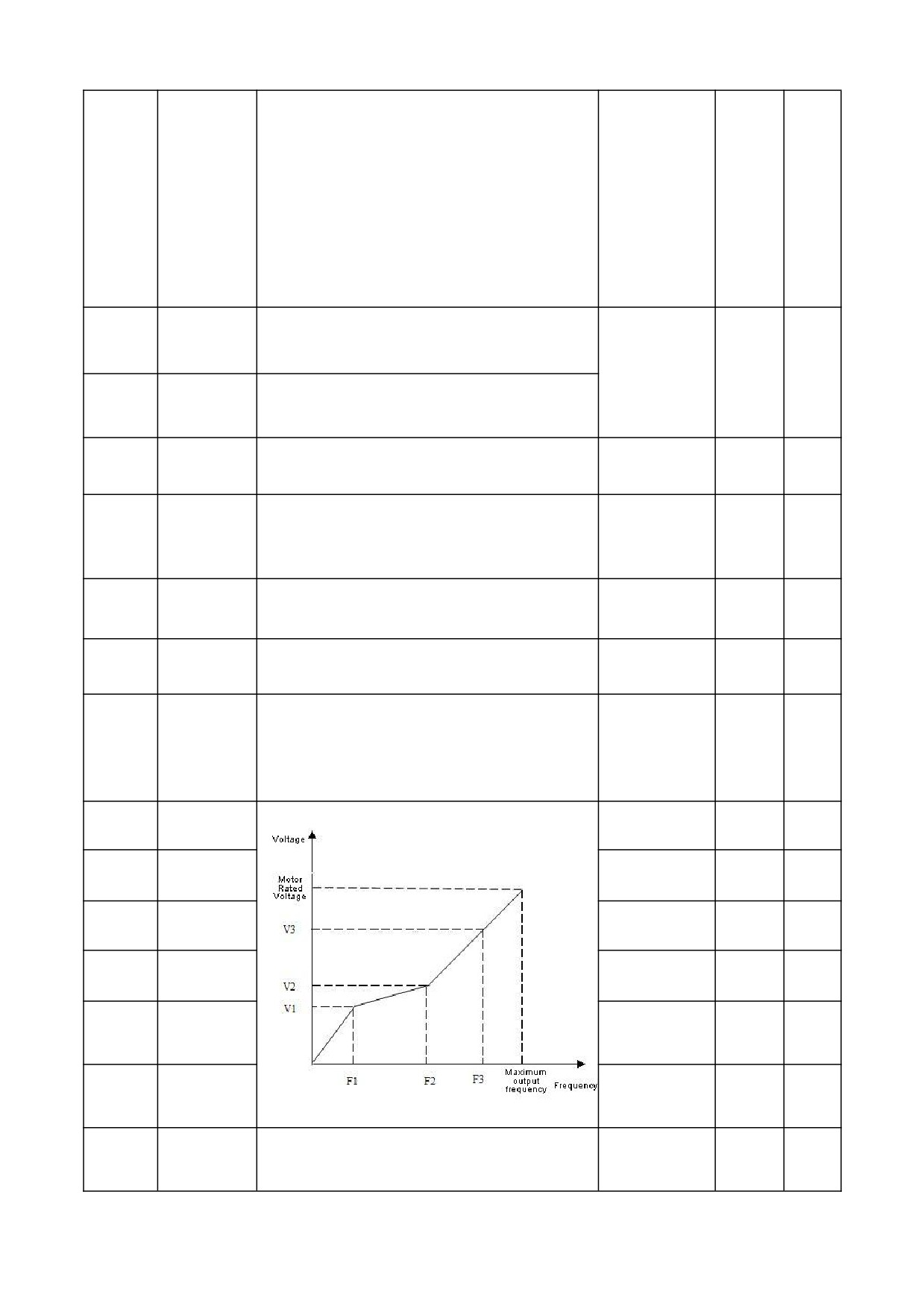
2: Multi-point VF curve
Manual torque lift.
Model
00.14
Torque boost
0.0~30.0%
○
This setting is a percentage relative to the rated voltage of the motor.
setting
Torque boost
This setting is the lifting cut-off frequency point when manual torque is
00.15
0.0~50.0Hz
15.0Hz
×
cutoff frequency
lifted.
When silent operation is needed, the carrier frequency can be
2.0~16.0KHz
Carrier frequency
Model
00.16
appropriately increased to meet the requirements, but increasing the
0.4~3.0KW
4.0KHz
×
setting
setting
carrier frequency will increase the calorific value of the inverter.
4.0~5.5KW
3.0KHz
0.1~ Frequency
00.17
V/F frequency F1
12.5Hz
×
value 02
0.0 ~ voltage value
00.18
V/F Voltage V1
25.0%
×
V2
Frequency value
00.19
V/F frequency F2
01 ~ frequency
25.0Hz
×
value 03
Voltage value v1 ~
00.20
V/F Voltage V2
50.0%
×
voltage value V3
Frequency value
02 ~ rated
00.21
V/F frequency F3
37.5Hz
×
frequency of motor
【 04.03】
Voltage value v2 ~
100.0% * uoute (rated
00.22
V/F Voltage V3
75.0%
×
voltage of motor
[04.00])
Set any non-zero number, and wait for 3 minutes or RESTART before it
00.23
User password
0~9999
0
○
takes effect.
17
0:0.1Hz
1:1Hz
Selection of
Note:
00.24
frequency display
0~1
0
○
When setting this parameter, be sure to check the frequency-related
resolution
parameters such as maximum output frequency (00.04), upper frequency
limit (00.05), rated frequency of motor (04.03), etc.
01 groups- Auxiliary operating parameters
Minimum unit
Factory
Change
Function
Name
Setting range
setting
code
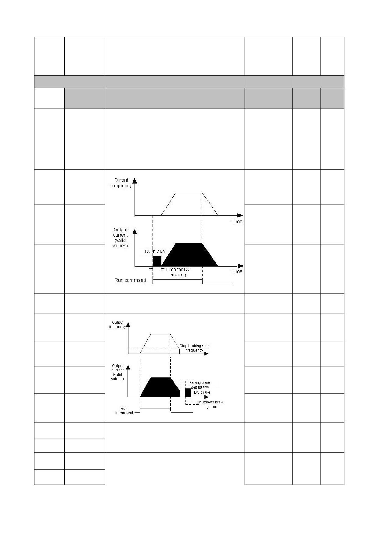
LED unit: starting mode
0: starting from starting frequency
1: DC braking first and then starting from starting frequency
2:Reserved
01.00
Starting mode
Ten LED bits: power failure or abnormal restart mode
0000~0012
00
×
0: invalid
1: starting from starting frequency
LED hundred bits:Reserved
LED thousand bits:Reserved
01.01
Starting frequency
0.0~50.0Hz
1.0Hz
○
Starting DC
0.0
~ 50.0% rated
01.02
0.0%
○
braking Voltage
Voltage of × motor
Starting DC
01.03
0.0~30.0s
0.0s
○
braking time
0: Deceleration stop
01.04
Stop mode
0~1
0
×
1: Free stop
Start frequency of
0.0 ~ upper limit
01.05
DC braking during
0.0Hz
○
frequency
stop
Stop DC braking
0.0 ~ 50.0% rated
01.06
0.0%
○
Voltage
Voltage of motor
Time for DC
01.07
braking during
0.0~30.0s
0.0s
×
stop
Waiting time for
01.08
DC braking during
0.00~99.99s
0.00s
×
stop
Forward jog
01.09
frequency
Set the jog FWD and REV rotation frequency
0.0~50.0Hz
10.0Hz
○
Reverse jog
01.10
frequency
0.1~999.9S
Jog acceleration
01.11
0.4~4.0KW
time
Model
Setting acceleration and deceleration time of JOG
10.0S
○
setting
Jog deceleration
5.5~7.5KW
01.12
time
15.0S
18
0.0
~ upper limit
01.13
Jump frequency
0.0Hz
○
frequency
By setting the jumping frequency and range, the frequency inverter can
avoid the mechanical resonance point of the load.
01.14
Jump range
0.0~10.0Hz
0.0Hz
○
0: Potentiometer+digital frequency 1
1: Potentiometer+digital frequency 2
2: Potentiometer +AI
3: Digital frequency 1+AI
Frequency
4: Digital frequency 2+AI
01.15
combination given
0~9
0
×
5: Digital frequency 1+ multi-speed
mode
6: Digital frequency 2+ multi-speed
7: Potentiometer+Multistage Speed
8: AI+PLC (superposition in the same direction)
9: Reserved
LED bit: PLC enable control
0: invalid
1: valid
LED ten bits: Operation mode selection
0: single cycle
Programmable
1:Continuous circulation
operation control
2:The final value is maintained after a single loop
01.16
0000~1221
0000
×
(simple PLC
LED hundred bits: starting mode
operation)
0:Restart from the first segment
1:Start from the stage of stop (failure) time
2: Start from the stage and frequency of stop (failure) time
LED thousand bits: power-off storage option
0: do not store
1: store
-upper limit
5.0Hz
○
Multi speed
01.17
Set the segment speed 1 frequency
frequency ~ upper
frequency 1
limit frequency
-upper limit
10.0Hz
○
Multi speed
01.18
Set the segment speed 2 frequency
frequency ~ upper
frequency 2
limit frequency
-upper limit
15.0Hz
○
Multi speed
01.19
Set the segment speed 3 frequency
frequency ~ upper
frequency 3
limit frequency
-upper limit
20.0Hz
○
Multi speed
01.20
Set the segment speed 4 frequency
frequency ~ upper
frequency 4
limit frequency
-upper limit
25.0Hz
○
Multi speed
01.21
Set the segment speed 5 frequency
frequency ~ upper
frequency 5
limit frequency
-upper limit
37.5Hz
○
Multi speed
01.22
Set the segment speed 6 frequency
frequency ~ upper
frequency 6
limit frequency
-upper limit
50.0Hz
○
Multi speed
01.23
Set the segment speed 7 frequency
frequency ~ upper
frequency 7
limit frequency
Set the running time of segment speed 1 (the unit is selected by [01.35],
Stage 1
running
01.24
and the default is seconds)
0.0~999.9s
10.0s
○
time
Set the running time of segment speed 2 (the unit is selected by [01.35],
Stage 2
running
01.25
and the default is seconds)
0.0~999.9s
10.0s
○
time
Stage 3
running
Set the running time of segment speed 3 (the unit is selected by [01.35],
01.26
0.0~999.9s
10.0s
○
time
and the default is seconds)
Set the running time of segment speed 4 (the unit is selected by [01.35],
Stage 4
running
01.27
and the default is seconds)
0.0~999.9s
10.0s
○
time
Stage 5
running
Set the running time of segment speed 5 (the unit is selected by [01.35],
01.28
0.0~999.9s
10.0s
○
time
and the default is seconds)
Stage 6
running
Set the running time of segment speed 6 (the unit is selected by [01.35],
01.29
0.0~999.9s
10.0s
○
time
and the default is seconds)
Set the running time of segment speed 7 (the unit is selected by [01.35],
Stage 7
running
01.30
and the default is seconds)
0.0~999.9s
10.0s
○
time
19
LED bit: Phase 1 acceleration and deceleration time
0~1
LED ten bits:Stage 2 Acceleration and deceleration time
Stage Select 1 for
0~1
01.31
acceleration and
0000~1111
0000
○
LED hundred bits:Stage 3 Acceleration and deceleration time
deceleration time
0~1
LED thousand bits:Stage 4 Acceleration and deceleration time
0~1
LED bit: Phase 5 acceleration and deceleration time
0~1
Stage Select 2 for
LED ten bits:Stage 6 Acceleration and deceleration time
01.32
acceleration and
0~1
000~111
000
○
deceleration time
LED hundred bits:Stage 7 Acceleration and deceleration time
0~1
LED thousand bits:Reserved
Acceleration
0.1~999.9s
01.33
time 2
0.4~4.0KW
Set the acceleration and deceleration time 2
10.0s
○
10.0s
Deceleration
01.34
5.5~7.5KW
15.0s
time 2
LED bit: process PID time unit
LED ten bits: simple PLC time unit
LED hundred bits: regular acceleration and deceleration time unit
Time unit
01.35
LED thousand bits: reserved
000~211
000
×
selection
0: 1 second
1: 1 minute
2: 0.1 second
Forward and
The transition time for the inverter to wait at the 0Hz during the transition
01.36
reverse dead
from the forward to the reverse operation, or from the reverse operation
0.0~999.9s
0.0
○
zone time
to the forward.
Group 02-analog and digital input and output parameters
Function
Factory
Name
Setting range
Minimum unit
Change
code
setting
AI input lower limit
02.00
0.00~【02.01】
0.00V
○
Voltage
Set AI upper and lower limit voltage
AI input upper limit
02.01
【02.01】~10.00V
10.00V
○
Voltage
AI lower limit
02.02
0.0%
○
corresponding setting
Set AI upper and lower limits corresponding to the percentage of the
-100.0% ~ 100.0%
AI upper limit
upper limit frequency [00.05].
02.03
100.0%
○
corresponding setting
02.04~02.07
Reserved
Reserved
Reserved
Reserved
○
The analog input
This parameter is used to filter the input signals of AI and panel
02.08
Signal filtering time
0.1~5.0s
0.1s
○
potentiometer to eliminate the influence of interference.
constant.
Analog input
When the analog input signal fluctuates frequently near a given value,
02.09
anti-shake deviation
the frequency fluctuation caused by this fluctuation can be
0.00~0.10V
0.00V
○
limit
suppressed by setting 02.09.
0:Output frequency
1: output current
Function Selection of
2:revolving speed of motor
02.10
0~5
0
○
AO terminal
3:Output voltage
4:AI
5:Reserved
AO output lower limit
0.00V
○
02.11
0.00~10.00V
Set AO output upper and lower limit
AO output upper limit
0.00~20.00mA
10.00V
○
02.12
0:idle control terminal
1: Forward JOG
Input terminal DI1
2: Reverse JOG
02.13
0~30
3
×
function
3: Forward (FWD)
4: Reverse (REV)
5: Three-wire operation control
20
6. Free stop control
7: External STOP signal input (STOP)
8: External reset signal input (RST)
Input terminal DI2
02.14
9: External fault normally open (NO) input
0~30
4
×
function
10: Frequency increment command (UP)
11: frequency decrement command (DOWN)
13: Multi-speed selection S1
14: Multistage speed selection S2
15: Multistage speed selection S3
16: Run command channel is forced to terminal
Input terminal DI3
02.15
17: Run command channel is forced to communication
0~30
0
×
function
18: DC braking Command when stop
19: The frequency command is switched to AI
20: The frequency command is switched to digital frequency
1
21: The frequency command is switched to digital frequency
2
Input terminal DI4
02.16
22: Reserved
0~30
0
×
function
23: Counter clear signal
24: Counter trigger signal
25: Timer reset signal
26: Timing trigger Signal
Input terminal DI5
27: Select the acceleration and deceleration time group
02.17
0~30
0
×
function
28: Pendulum frequency pause (stop at current frequency)
29: Pendulum frequency reset (return to center frequency)
30: external stop/reset signal input (STOP/RST)
0: Two-wire control mode 1
1: Two-wire control mode 2
FWD/REV terminal
2: Three-wire control mode 1
02.18
0~5
0
×
control mode
3: Three-wire control mode 2
4: Three-wire control mode 3
5: Reserved
Selection of terminal
0: invalid terminal operation command at power-on
02.19
function detection
0~1
0
×
1: valid terminal operation command at power-on.
when power on
0: Reserved
1: Inverter is ready to run
2: Inverter in running
3. Inverter in zero speed running
4: External fault stop
5: Frequency inverter fault
02.20
R output setting
0~17
5
○
6. Frequency/speed arrival signal (FAR)
7: Frequency/Speed Level Detection Signal (FDT)
8: The output frequency reaches the upper limit
9: Output frequency reaches lower limit
10: Inverter overload pre-alarm
11: Timer overflow signal
12: counter detection signal
13: counter reset signal
Y Open collector
14: Auxiliary motor
02.21
0~17
0
○
output
15: Forward
16: Reverse
17: Output when the frequency arrival to the speed detection level
02.22
R close delay
Delay from state change of relay
0.0~255.0s
0.0s
×
R open delay
02.23
Frequency reaches
When the output frequency is within the positive and negative
02.24
FAR detection
detection width of the set frequency, the terminal outputs an effective
0.0Hz~15.0Hz
5.0Hz
○
amplitude
signal (low level).
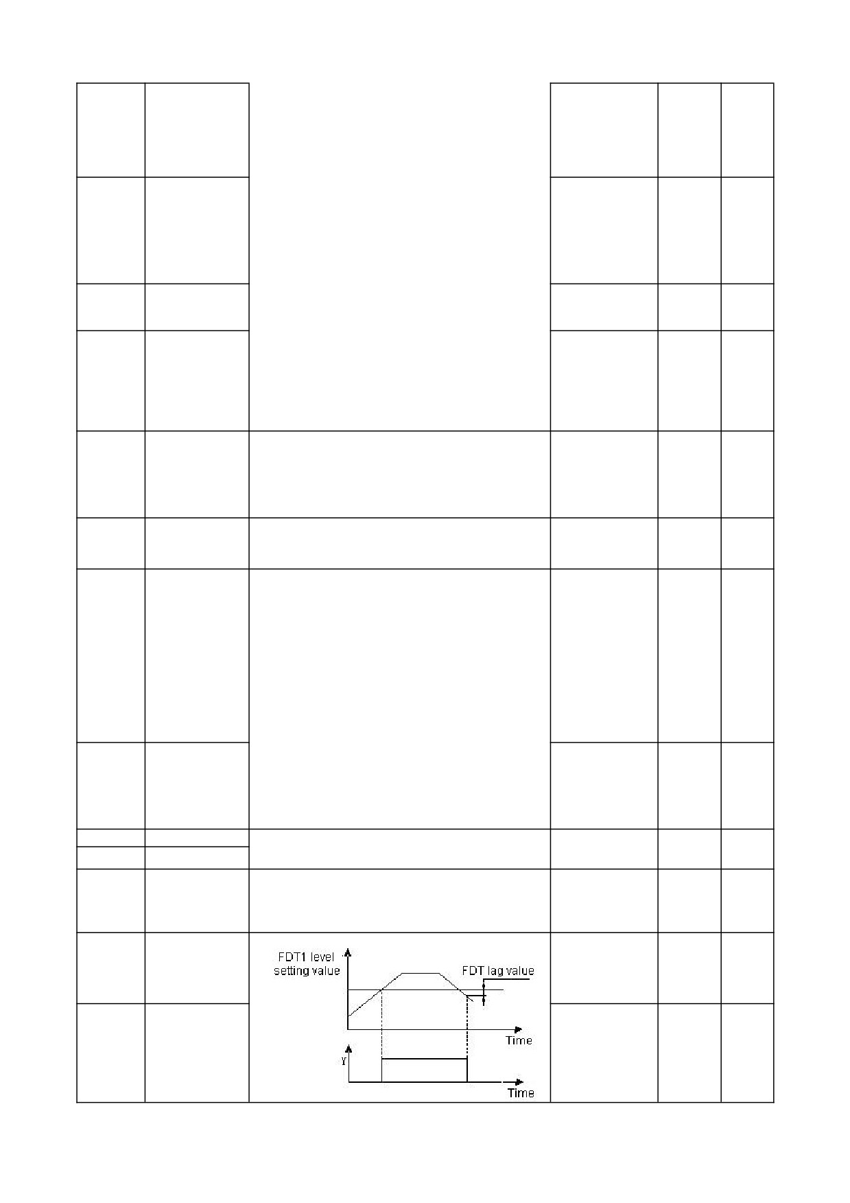
FDT1 level setting
0.0Hz ~
~
upper
02.25
10.0Hz
○
value
limit frequency
02.26
FDT lag value
0.0~30.0Hz
1.0Hz
○
21
The function code is the frequency modification rate when setting the
UP/DOWN terminal
UP/DOWN terminal as frequency set , that is, the UP/DOWN terminal
0.1Hz~
02.27
1.0Hz/s
○
modification rate
is short-circuited with the GND terminal for 1s, and the frequency
99.9Hz/s
changes.
0: indicates the electrical level trigger mode
Input terminal pulse
1: indicates the pulse trigger mode
02.28
trigger mode setting
0~1FH
0
○
Note:
(DI1~DI5)
DI1~DI5 correspond to 1H, 2H, 4H, 8H and 10H in hexadecimal.
0: indicates positive logic, that is, the DI terminal is connected to GND
and GND is valid, and the disconnection is invalid
Input terminal valid
1: It means anti-logic, that is, DI terminal is not connected to the GND
02.29
logic setting
0~1FH
0
○
terminal and GND is invalid, and the disconnection is valid
(DI1~DI5)
Note:
DI1~DI5 correspond to 1H, 2H, 4H, 8H and 10H in hexadecimal.
02.30
DI1 filter coefficient
0~9999
5
○
Used to set the sensitivity of the input terminal. If the digital input
02.31
DI2 filter coefficient
terminal is susceptible to interference and causes misoperation, this
0~9999
5
○
parameter can be increased to enhance the anti-interference ability,
02.32
DI3 filter coefficient
0~9999
5
○
but the sensitivity of the input terminal will be reduced if the setting is
02.33
DI1 filter coefficient
too large.
0~9999
5
○
1: represents 2ms scanning time unit
02.34
DI2 filter coefficient
0~9999
5
○
03 group -PID parameters
Function
Name
Minimum unit
Factory
Change
Setting range
code
setting
LED bit: PID regulation characteristics
0:invalid
1: positive effect
When the feedback signal is greater than the given quantity of PID,
the output frequency of the inverter is required to decrease (that is,
reduce the feedback signal).
2: negative effect
When the feedback signal is greater than the given quantity of PID,
the output frequency of the inverter is required to rise (that is, reduce
the feedback signal).
LED ten bits: PID given input channel
0: keypad potentiometer
PID given quantity is given by potentiometer on the keypad.
1 Number given
PID given quantity is given by numbers and set by function code
03.01.
03.00
PID function setting
2 Given pressure (MPa, Kg)
0000~2122
1010
×
Set the given pressure on 03.01 and 03.18.
LED hundred digits: PID feedback input channel
0: AI
1: Reserved
LED thousand bits: PID sleep selection
0: invalid
1: normal sleep
Specific parameters such as 03.10 ~ 03.13 should be set in this
method.
2. Disturbed sleeping
The parameter setting is the same as when the sleep mode is
selected as 0. If the PID feedback value is within the range of the set
value of 03.14, the sleep delay time will be maintained and then the
disturbance sleep will be entered. When the feedback value is less
than the wake-up threshold (PID polarity is positive), wake up
immediately.
Use the operation keypad to set the given quantity of PID control. This
function is effective only when the PID given channel selects digital
Given a numerical
03.01
given (03.00 ten digits are 1 or 2). If 03.00 digit is 2, it is used as
0.0~100.0%
0.0%
○
setting
pressure reference, and this parameter is consistent with the unit of
03.18.
When the feedback channel is inconsistent with the set channel level,
Feedback channel
03.02
this function can be used to adjust the gain of the feedback channel
0.01~10.00
1.00
○
gain
signal.
22
The speed of PID adjustment is set by two parameters: proportional
03.03
Proportional gain P
0.01~5.00
2.00
○
gain and integration time. For fast adjustment, it is necessary to
increase proportional gain and reduce integration time; for slow
03.04
Integration time Ti
0.1~50.0s
1.0s
○
adjustment, it is necessary to reduce proportional gain and increase
integration time.
03.05
Derivative time Td
Generally, differential time is no necessary to set
0.1~10.0s
0.0s
○
The larger the sampling period, the slower the response, but the
03.06
Sampling period T
better the interference signal suppression effect, so it is generally
0.1~10.0s
0.0s
○
unnecessary to set it.
The deviation limit is the ratio of the absolute value of the deviation
between the feedback amount and the given amount of the system.
03.07
Deviation limit
0.0~20.0%
0.0%
○
When the feedback amount is within the deviation limit, the PID
adjustment will not act.
Closed loop preset
0.0 ~upper limit
03.08
0.0Hz
○
frequency
frequency
Frequency and running time of inverter before PID is put into
operation
Preset
frequency
03.09
0.0~999.9s
0.0s
×
holding time
If the actual feedback value is greater than the set value, and the
frequency output by the frequency inverter reaches the lower limit
Sleep
threshold
03.10
frequency, the frequency inverter will enter the sleep state after the
0.0~150.0%
100.0%
○
coefficient
delay waiting time defined in 03.12 (i.e., running at zero speed); The
value is a percentage of the PID set value.
If the actual feedback value is less than the set value, the frequency
Awakening threshold
inverter will get out of sleep and start working after the delay waiting
03.11
0.0~150.0%
90.0%
○
coefficient
time defined in 03.13; The value is a percentage of the PID set value.
Set up Sleep delay time
03.12
Sleep delay time
0.0~999.9s
100.0s
○
Set up Wake delay time
03.13
Wake delay time
0.0~999.9s
1.0s
○
Deviation
between
feedback and set
03.14
This function parameter is only valid for disturbance sleep mode
0.0~10.0%
0.5%
○
pressure
when
entering sleep
Delay time of burst
03.15
Set the burst tube detection delay time
0.0~130.0s
0.0S
○
detection
When the feedback pressure is greater than or equal to this set value,
the explosion failure “EPA0” will be reported after the explosion delay
High pressure
03.16
at 03.15, and when the feedback pressure is less than this set value,
0.0~200.0%
150.0%
○
detection threshold
the explosion failure “EPA0” will automatically reset; The threshold is
a percentage of the given pressure.
When the feedback pressure is less than this set value, the explosion
failure “EPA0” will be reported after the explosion delay at 03.15, and
Low pressure
03.17
when the feedback pressure is greater than or equal to this set value,
0.0~200.0%
50.0%
○
detection threshold
the explosion failure “EPA0” will automatically reset; The threshold is
a percentage of the given pressure.
Measurement range
0.00~99.99
03.18
Set the maximum range of the sensor
10.00MPa
○
of sensors
(MPa、Kg)
04 group -advanced functions parameters
Function
Factory
Name
Setting range
Minimum unit
Change
code
setting
0~500V:380V
Model
04.00
Motor rated voltage
×
0~250V:220V
setting
Model
04.01
Motor rated current
0.1~999.9A
×
Setting of motor parameters
setting
Model
04.02
Motor rated speed
0~9999RPM
×
setting
04.03
Motor rated frequency
1.0~999.9Hz
50.0Hz
×
Model
○
04.04
Motor stator resistance
Set the motor stator resistance
0.001~20.000Ω
setting
Model
×
04.05
Motor no-load current
Set the motor no-load current
0.1~【04.01】
setting
23
0: invalid
04.06
AVR function
1: the whole process is effective
0~2
0
×
2: invalid only when decelerating
0: Automatic control mode
04.07
Cooling fan control
0~1
0
○
1: runs all the time during power on
When the number of fault resets is set to 0, there is no automatic reset
Automatic fault reset
04.08
function, and it can only be reset manually. When it is set to 10, the
0~10
0
×
times
number of times is unlimited, that is, countless times.
Automatic fault reset
04.09
Set the automatic fault reset interval
0.5~25.0s
3.0s
×
interval
Energy consumption
If the internal DC bus voltage of the frequency inverter is higher than
04.10
330~380/660~800V
350/780V
○
braking starting voltage
the starting voltage of energy consumption braking, the built-in
braking unit will act. If a braking resistor is connected at this time, the
Energy consumption
04.11
voltage energy raised inside the frequency inverter will be released
10~100%
100%
○
braking action ratio
through the braking resistor, and the DC voltage will fall down.
Over modulation
0: invalid
04.12
0~1
0
×
function selection
1: valid
0: full frequency seven segments
04.13
PWM mode
1: full frequency five segments
0~2
0
×
2: seven segments to five segments
The speed of asynchronous motor will decrease after being loaded.
Slip compensation
Slip compensation can make the speed of motor close to its
04.14
0~200%
100%
×
coefficient
synchronous speed, thus making the speed control accuracy of motor
higher. This coefficient is only valid for ordinary V/F mode.
0: invalid
Slip compensation
04.15
1: low frequency compensation
0~1
0
×
mode
Note: This parameter is only valid for advanced V/F.
0: invalid
Self-learning of motor
04.16
1: Static self-learning
(STAR is displayed immediately when it is
0~1
0
×
parameters
started. After finished, END is displayed and disappears after 1s
Model
04.17
Motor rated Power
0.0~2000.0KW
○
setting
Rotor resistance of
Model
04.18
0.00~200.00Ω
○
motor
After the rated power of the motor is changed to 04.17, 04.01, 04.02,
setting
Inductance of stator
04.04, 04.05, 04.18 ~ 04.20 are automatically updated as the
Model
04.19
0.00~200.00mH
○
and rotor of motor
default parameters of the motor with corresponding power.
setting
Mutual inductance
Model
04.20
between stator and
0.00~200.00mH
○
setting
rotor of motor
Speed loop 1
04.21
1~100
30
×
Proportional gain
Speed loop 1 Integral
04.22
0.01~10.00S
0.50
○
time
Low frequency
04.23
0.0~10.0Hz
5.0
×
switching point
Function codes 04.21 ~ 04.26 are valid in vector control mode.
By setting proportional gain P and integration time I, the speed
Speed loop 2
04.24
response characteristics of vector control are changed.
1~100
20
○
Proportional gain
Speed loop 2 Integral
04.25
0.01~10.00S
1.00
○
time
High frequency
04.26
【04.23】~320.0Hz
10.0
×
switching point
In vector control mode, this parameter is used to adjust the speed
Vector Slip
stability accuracy of the motor. When the motor is overloaded and the
04.27
50% ~ 200%
100
○
compensation
speed is low, increase this parameter, otherwise decrease this
parameter.
speed loop filter time
04.28
Set the speed loop filtering time
0.000~1.000S
0.010
○
constant
04.29
Reserved
-
-
0
◆
04.30
speed loop torque limit
The set value is a percentage of the rated current of the motor
0.0% ~ 200.0%
150.0
○
24
05 Group- Protective Function parameters
Function
Name
Setting range
Minimum unit
Factory
Change
code
setting
LED unit: motor overload protection option
0: invalid
1. valid
LED Ten bits: PID feedback disconnection protection
0: invalid
1: protection action and free stop
05.00
Protection settings
LED hundred bits: 485 communication failure handling
0000~1211
0001
×
0: protection action and free stop
1: alarm but maintain the status operation;
2: alarm and stop in the set way
LED thousand bits: Oscillation Suppression
0: invalid
1: valid
The motor overload protection coefficient is the percentage of the
Motor overload
05.01
rated current value of the motor to the rated output current value of
30% ~ 110%
100%
×
protection coefficient
the inverter.
Undervoltage
This function code specifies the allowable lower limit voltage of DC
05.02
50~280/50~480V
180/360V
×
protection level
bus when the inverter works normally.
Voltage limiting factor
This parameter is used to adjust the ability of the inverter to suppress
05.03
0: off, 1
~ 255
1
×
during deceleration
overvoltage during deceleration.
Overvoltage limit
Overvoltage limit level defines the operating voltage during
05.04
350~400/660~850V
375/700V
×
level
overvoltage stall protection
Current limiting
This parameter is used to adjust the ability of inverter to restrain
05.05
coefficient during
0: off, 1
~ 99
10
×
overcurrent during acceleration.
acceleration
Current limiting
This parameter is used to adjust the ability of inverter to restrain
05.06
coefficient during
0: off, 1
~ 10
0
×
overcurrent in the process of constant speed.
constant speed
The current limiting level defines the current threshold of automatic
05.07
Current limiting level
current limiting operation, and its set value is the percentage relative
50% ~ 200%
160%
×
to the rated current of the inverter.
This value is the percentage of PID given quantity. When the
Feedback
feedback value of PID is continuously less than the feedback
05.08
disconnection
disconnection detection value, the inverter will make corresponding
0.0~100.0%
0.0%
×
detection value
protection actions according to the setting of 05.00, and it will be
invalid when 05.08=0.0%.
Feedback
05.09
disconnection
Delay time before protection action after feedback disconnection.
0.1~999.9S
10.0s
×
detection time
Inverter
Overload
The current threshold for the overload warning action of the inverter.
05.10
0~150%
120%
○
pre-alarm level
The set value is a percentage of the rated current of the inverter.
The delay time between the output current of inverter continuously
Inverter
Overload
05.11
exceeding the horizontal amplitude of overload pre-alarm (05.10) and
0.0~15.0s
5.0s
×
pre-alarm delay
the output of overload pre-alarm signal.
0: invalid
05.12
JOG priority enable
0~1
0
×
1: when the inverter is running, the jog priority is the highest
Oscillation
05.13
suppression
0~200
30
○
coefficient
Amplitude
In case of motor oscillation, it is necessary to set the effective value of
05.14
suppression
0~12
5
○
05.00 thousand bits, turn on the oscillation suppression function, and
coefficient
then adjust it by setting the oscillation suppression coefficient. In
The Lower limit
general, the oscillation amplitude is large, so it is unnecessary to set
frequency of
05.15
the oscillation suppression coefficient of 05.13, 05.14
~ 05.16; In
0.0~【05.16】
5.0Hz
○
oscillation
case of special occasions, they should be used together from 05.13~
suppression
05.16.
The upper limit
frequency of
05.16
【05.15】~【00.05】
45.0Hz
○
oscillation
suppression
25
LED bit:In acceleration
0:invalid
1:valid
LED ten bits:In deceleration
Selection of
0:invalid
05.17
wave-by-wave
000~111
011
×
1:valid
current limit
LED hundred-bits: In constant speed
0:invalid
1:valid
LED Thousand bits:Reserved
When the ratio of the maximum value to the minimum value in the
Output phase lost
three-phase output current is greater than this coefficient and the
05.18
protection detection
duration exceeds 6 seconds, the frequency inverter reports the output
0.00~20.00
2.00
○
coefficient
current imbalance fault EPLI;;Output open-phase protection is invalid
when 05.18=0.00.
Frequency drop
0: the instantaneous
coefficient of
05.19
Set the instantaneous power-down frequency drop factor
stop function is invalid
0
○
instantaneous power
1~9999
failure
Instantaneous power
220V:180~330V
down loss frequency
250V
Model
05.20
Instantaneous power down loss frequency reduction voltage point
×
reduction voltage
380V:300~550V
setting
point
450V
06 group: communication parameters
Function
Factory
Name
Setting range
Minimum unit
Change
code
setting
06.00
Local Address
Set the local address, 0 is the broadcast address.
0~247
1
×
LED bit:baud rate selection
0:9600BPS
1:19200BPS
2:38400BPS
LED ten bits:data format
0:no parity
MODBUS
1:even parity check
06.01
communication
2:Odd Parity Check
0000~0322
0000
×
configuration
LED hundred bits:Communication response mode
0:normal response
1:Only respond to the slave address
2:no response
3:The slave machine does not respond to the free stop instruction of
the host machine in broadcast mode
LED thousand bits:Reserved
If the machine does not receive the correct data signal within the
time interval defined by this function code, then the machine thinks
that the communication has failed, and the frequency inverter will
communication
06.02
decide whether to protect or maintain the current operation
0.1~100.0s
10.0s
×
timeout check-out time
according to the setting of the communication failure action mode;
When this value is set to 0.0, RS485 communication timeout
detection is not performed.
This function code defines the intermediate time interval between
receiving the data frame of the inverter and sending the response
local machine
06.03
data frame to the upper computer. If the response time is less than
0~200ms
5ms
×
response delay time
the system processing time, the system processing time shall
prevail.
This function code is used to set the weight coefficient of frequency
instruction received by inverter as slave through RS485 interface,
and the actual operating frequency of this machine is equal to the
Proportional linkage
06.04
value of this function code multiplied by the value of frequency
0.01~10.00
1.00
○
coefficient
setting instruction received through RS485 interface. In the linkage
control, this function code can set the ratio of operating frequency of
multiple inverters.
Multi-vendor
06.05
agreement selection
Reserved
0~3
0
×
(reserved)
26
07 Group- supplementary Function parameters
Function
Factory
Name
Setting range
Minimum unit
Change
code
setting
LED bit: count arrival processing
0: One-cycle counting, stop output
1: One-cycle counting, continue to output
2: Cycle counting, stop output
3: Cycle counting, continue to output
Counting and timing
LED ten bits: Reserved
07.00
000~303
103
×
mode
LED hundred bits: timing arrival processing
0: One-cycle counting, stop output
1: One-cycle counting, continue to output
2: Cycle counting, stop output
3: Cycle counting, continue to output
LED thousand bits: reserved
The counter reset
07.01
Set the counter reset value
【07.02】~9999
1
○
value setting
Setting of counter
07.02
Set the counter detection value
0~【07.01】
1
○
detection value
07.03
Timing setting
Set the timing time
0~9999s
0s
○
07.04~07.07
Reserved
-
-
0
○
Swing frequency
07.08
0: prohibited
1: valid
0~1
0
×
control
0: fixed swing
The reference value of swing is the maximum output frequency
Swing frequency
07.09
(00.04).
0~1
0
×
control
1: variable swing
The reference value of the swing is the given channel frequency.
Swing frequency stop
0: start according to the state memorized before stop
07.10
starting mode
0~1
0
×
1: restart starting
selection
Swing frequency
The swing frequency amplitude is a percentage of the maximum
07.11
0.0~100.0%
0.0%
○
amplitude
output frequency (00.04).
This function code refers to the amplitude of rapid decline after the
frequency reaches the upper limit frequency of the swing frequency,
and of course it also refers to the amplitude of rapid rise after the
07.12
Jump frequency
0.0~50.0%
0.0%
○
frequency reaches the lower limit frequency of the swing frequency.
This value is a percentage relative to the swing frequency amplitude
(07.11). If it is set to 0.0%, there will be no sudden jump frequency.
Swing frequency rise
Running time from the lower frequency of the swing frequency to the
07.13
0.1~3600.0s
5.0
○
time
upper frequency of the swing frequency.
Pendulum frequency
The running time from the upper swing frequency to the lower swing
07.14
0.1~3600.0s
5.0
○
falling time
frequency.
Frequency delay of
07.15
swing frequency upper
0.1~3600.0s
5.0
○
limit
Set the upper and lower frequency delays of pendulum frequency.
Frequency delay of
07.16
swing frequency lower
0.1~3600.0s
5.0
○
limit
Group 08-manage and display parameters
Function
Name
Factory
Setting range
Minimum unit
Change
code
setting
Main parameter
For example: 08.00=2, that is, select the output voltage (D-02), then
08.00
monitoring during
the default display item on the main monitoring interface is the
0~30
0
○
operation
current output voltage value.
For example: 08.01=3, that is, bus voltage (d-03) is selected, then
Main parameter
08.01
the default display item of the main monitoring interface is the
0~30
1
○
monitoring during stop
current bus voltage value.
Auxiliary parameter
display during
For example: 08.02=4, that is, select the output Current (D-02), then
08.02
operation (only valid
the default display item on the main monitoring interface is the
0~30
4
○
for dual display
current output voltage value.
keypad)
Auxiliary parameter
For example: 08.03=3, that is, bus voltage (d-03) is selected, then
display during stop
08.03
the default display item of the main monitoring interface is the
0~30
3
○
(only valid for dual
current bus voltage value.
display keypad)
27
Motor speed display
It is used to correct the display error of speed scale, and has no
08.04
0.01~99.99
1.00
○
coefficient
influence on the actual speed.
0: No-operation
The inverter is in normal parameter reading and writing state. Set
value of function code
Whether it can be changed depends on the setting state of the user
password and the current working state of the inverter.
Initialization of the
1: Restore the factory settings
08.05
0~2
0
×
parameter
All user parameters are restored to the factory settings according
to the model.
2:Clear fault record
Clear the contents of fault records (d-19~d-24). After the
operation is completed, this function code is cleared to 0
automatically.
0:JOG
1: FWD and REV switch
08.06
FUNC key settings
0~3
0
×
2: clear ▲/▼ key frequency setting
3: REV (at this time, the RUN key defaults to FWD)
Group d-monitoring parameter group
Function
Factory
Name
Range
Minimum unit
Change
code
setting
d-00
Output frequency(Hz)
0.0~999.9Hz
0.1Hz
0.0Hz
◆
d-01
Set frequency(Hz)
0.0~999.9Hz
0.1Hz
0.0Hz
◆
d-02
Output voltage(V)
0~999V
1V
0V
◆
d-03
DC Bus voltage(V)
0~999V
1V
0V
◆
d-04
Output current(A)
0.0~999.9A
0.1A
0.0A
◆
Model
d-05
Motor speed (rpm)
0~60000rpm
1rpm
◆
setting
Analog input
d-06
0.00~10.00V/0.00~20.00mA
0.01V/0.01mA
0.00V/mA
◆
AI1(V/mA)
d-07
Reserved
-
0
0
◆
Analog input
d-08
0.00~10.00V/0.00~20.00mA
0.01V/0.01mA
0.00V/mA
◆
AO(V/mA)
-
d-09
Reserved
-
0
◆
PID pressure setting
0.00V/(MPa、
d-10
0.00~10.00V/0.00~99.99(MPa、Kg)
0.01V/(MPa、Kg)
◆
value
Kg)
PID pressure
0.00V/(MPa,
d-11
0.00~10.00V/0.00~99.99(MPa, Kg)
0.01V/(MPa, Kg)
◆
feedback value
Kg)
1s
d-12
Current count value
0~9999s
0s
◆
Current timing value
d-13
0~9999s
1s
0s
◆
(s)
Input terminal
d-14
0~1FH
1H
0H
◆
status(DI1-DI5)
d-15
Output status (Y/R)
0~3H
1H
0H
◆
Module temperature
0.0~132.3℃
0.1℃
0.0
◆
d-16
(℃)
Software
upgrade
d-17
2010~2026
1
2021
◆
date (year)
Software
Upgrade
d-18
0~1231
1
0615
◆
Date (Month Day)
d-19
Secondary fault code
0~19
1
0
◆
d-20
The last fault code
0~19
1
0
◆
Output frequency in
d-21
0.0~999.9Hz
0.1Hz
0.0Hz
◆
the last fault (Hz)
Output current during
d-22
0.0~999.9A
0.1A
0.0V
◆
the last fault (a)
Bus voltage at the last
d-23
fault (v)
0~999V
1V
0V
◆
28
Module temperature
d-24
during the last fault
0.0~132.3℃
0.1℃
0.0℃
◆
(℃)
Accumulated
d-25
operation time of
0~9999h
1h
0h
◆
frequency inverter (h)
0~FFFFH
BIT0: Run/Stop
BIT1: REV/FWD
BIT2:JOG
BIT3: DC braking
BIT4: reserved
BIT5: overvoltage limit
BIT6: Constant speed frequency reduction
BIT7: overcurrent limit
Bit8~9:
00-Zero speed
01- Acceleration
d-26
Inverter state
1H
0H
◆
10- Deceleration
11- Uniform speed
BIT10: Overload Pre-alarm
BIT11:Reserved
Bit12~13 Run command channel:
00- Panel
01- Terminal
10- Reserved
Bit14~15: DC bus voltage status:
00- normal
01- low voltage protection
10- overvoltage protection
d-27
Software version
1.00~99.99
0.01
2.00
◆
Model
d-28
Power model
0.10~99.9KW
0.01KW
◆
setting
0.0
~ maximum output frequency [00.04]
Note:
the
running
Estimated frequency
d-29
frequency of the motor calculated from the estimated speed of the
0.1Hz
0.0Hz
◆
of motor
motor
d-30
Output torque
-200~+200%
1%
0%
◆
Group e-fault code
Fault code
Name
Possible reason of fault
Fault countermeasures
Code
Acceleration time is too short
Extended the acceleration time
Overcurrent in
E0C1
Low inverter power
Choose a frequency inverter with high power level
1
acceleration
Improper setting of V/F curve or torque boost
Adjust V/F curve or torque lift
Overcurrent in
Deceleration time is too short
Extended deceleration time
E0C2
2
deceleration
Low inverter power
Choose a frequency inverter with high power level
Low grid voltage
Check the input power supply
Overcurrent in uniform
E0C3
The load is mutated or abnormal
Check the load or reduce the load mutation
3
operation
Low inverter power
Choose a frequency inverter with high power level
Overvoltage during
Input voltage abnormal
Check the input power supply
EHU1
4
acceleration
Restart the rotating motor
Set to start after DC braking
Overvoltage during
Deceleration time is too short
Extended deceleration time
EHU2
5
deceleration
Input voltage abnormal
Check the input power supply
Overvoltage in
EHU3
Input voltage abnormal
Check the input power supply
6
uniform operation
overvoltage during
EHU4
Input voltage abnormal
Check the power supply voltage
7
stop
Undervoltage during
Check the power supply voltage or ask
the
ELU0
Input voltage is abnormal or relay is not pulled in
8
operation
manufacturer for service
29
ESC1
Inverter output short circuit or grounding
Check the motor wiring
Instantaneous overcurrent of frequency inverter
See overcurrent countermeasures
Power module failure
9
Abnormal control panel or serious interference
Seek services from manufacturers
Power device damage
Seek services from manufacturers
Ambient temperature is too high
Lower ambient temperatures
E-OH
Overheating radiator
Fan damaged
Replace the fan
10
Clogged air duct
Clear the air duct
Improper setting of V/F curve or torque boost
Adjust V/F curve or torque lift
Grid voltage is too low
Check the grid voltage
EOL1
Inverter overload
11
Acceleration time is too short
Extended the acceleration time
The motor is overloaded
Choose a frequency inverter with higher power
Improper setting of V/F curve or torque boost
Adjust V/F curve or torque lift
Grid voltage is too low
Check the grid voltage
EOL2
Motor overload
12
The motor is locked or the load mutation is too large
Check the load
Motor overload protection factor is not set correctly
correctly set Motor overload protection coefficient
External equipment
Disconnect External Equipment Fault Input Terminal
E-EF
External equipment fault input terminal closed
13
fault
and Clear Fault
Dual CPU
EPOF
CPU communication failure
Seek services from manufacturers
14
communication failure
Loose PID feedback circuit
Check the feedback connection
PID feedback
EPID
15
disconnection
The feedback amount is less than the disconnection
Adjust the detection input threshold
detection value
Does not match the baud rate of the upper computer
Adjust baud rate
Check whether the communication connection is
RS485
E485
RS485 channel interference
shielded and the wiring is reasonable. If necessary,
16
communication failure
consider connecting the filter capacitor in parallel
Communication timeout
Retry
ETUN
Motor tuning fault
Incorrect setting of motor parameters
Reset the motor parameters
17
Fault of current sampling circuit
ECCF
Current detection fault
Seek services from manufacturers
18
Auxiliary power failure
EEFROM reading and
EEEP
EEPROM fault
Seek services from manufacturers
19
writing error
Output phase loss
EPLI
Output U, V and W are out of phase
Check the output wiring
20
protection
The feedback pressure is less than the low pressure
Check the feedback connection or adjust the high and
EPAO
Tube bursting fault
detection threshold or greater than or equal to the
22
low pressure threshold
high pressure detection threshold
30
VI. Parameter description
00 groups-basic operating parameters
Function macro definition (temporarily reserved)
00.00
0~10
0
0:General model
1:Single pump constant pressure water supply mode
2:Reserved
3:Reserved
4:Engraving machine mode
5~10:Reserved
Note: Initialize the parameters first, and then set the macro function.
Motor control mode
00.01
0~2
-
0: Normal V/F control
When it is necessary to use a single inverter to drive more than one motor, the control method used when the motor parameter self-learning cannot be performed
correctly or the controlled motor parameters cannot be obtained through other ways. This control method is the most commonly used motor control method. This
control method can be used in any occasion that does not require high motor control performance.
1: Advanced V/F control
This control mode introduces the idea of magnetic flux closed-loop control, which can greatly improve the torque response of motor control in the full frequency
range, and enhance the torque output capability of the motor at low frequency. At the same time, it is not too sensitive to motor parameters like the field-oriented vector
control.This control mode is especially suitable for some occasions that have certain requirements for starting torque (such as wire drawing machines, ball mills, etc.).
2: Vector control (sensitivity of motor parameters)
A true vector control method. In addition to the high torque output performance of the magnetic flux control method, this control method also has the effect of
flexible torque output. It can be described as both rigid and flexible, but this control method is more sensitive to motor parameters. Use it after enabling the dynamic
self-learning of motor parameters, otherwise the effect will be poor.
Run command channel selection
00.02
0~2
0
This function code selects the physical channel where the inverter accepts operation commands such as running and stopping.
0: The operation panel runs the command channel
Operation control is implemented by the, RUN
,STOP/RESET
M-FUNC
and other keys on the operation panel.
1: Terminal operation command channel
Operation control is implemented by multi-function terminals defined as FWD, REV, JOG forward rotation, JOG reverse rotation and other functions.
2: Communication operation command channel
Operation control is implemented by the upper controller through communication.
Main frequency source A selection
00.03
0~7
0
0: Panel potentiometer setting
The operating frequency is adjusted by operating the potentiometer on the keyboard, and the range of the potentiometer's adjustment frequency is fixed from 0 to the
maximum output frequency [00.04].
1: Digital setting 1, panel
31
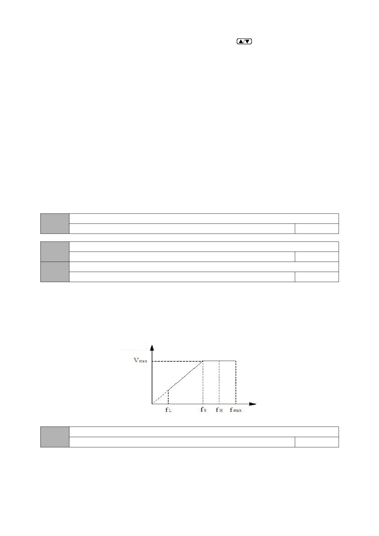
The initial value of the frequency setting is 00.08, which can be adjusted with the operation panel keys
or digital encoder. The modified frequency value
will be stored in 00.08 after power failure (if you want this frequency not to be stored, you can set 00.09 bits to 1 to achieve.
2: Digital setting 2, UP/DOWN terminal adjustment
The initial value of the frequency setting is 00.9, and the operating frequency is changed by the on/off of the multi-function terminal defined externally as the UP/DOWN
function (see the function number of the frequency increment and decrement item of the DI terminal in group 02 for details), when the UP terminal and the GND
terminal are closed , The frequency rises; when the DOWN terminal is closed with the GND terminal, the frequency drops; when the UP/DOWN terminal is closed or
disconnected with the GND terminal at the same time, the frequency remains unchanged. If you set the frequency to be stored when power off, the modified frequency
value will be stored in 00.9 after power off. The rate at which the UP/DOWN terminal modifies the operating frequency can be set by function code 02.27.
3: AI analog setting (0~10V/20mA)
The frequency setting is determined by the AI terminal analog voltage/current, the input range:
For DC 0~10V/20mA related settings, see the definition of function 02.00~02.03.
4: Combination given
When the combination is given, the combination setting mode is selected in 01.15.
5: reserved
6: Communication settings
Change the set frequency through the serial port frequency setting command. For details, see Group 06 communication parameters.
7: Reserved
Maximum output frequency
00.04
MAX{50.0, 【00.05】}~ 999.9Hz
50.00
Upper limit frequency
00.05
MAX{0.1Hz,【00.06】}~【00.04】
50.00
Lower limit frequency
00.06
0.0Hz~【00.05】
0.00
The maximum output frequency is the highest frequency that the inverter allows to output, and is the basis for the acceleration and deceleration time setting, as
shown in the following figure, fmax;
The basic operating frequency is the minimum frequency when the inverter outputs the highest voltage, generally the rated frequency of the motor, as shown in the
following figure fb; the maximum output voltage Vmax is the corresponding output voltage when the inverter outputs the basic operating frequency, generally the motor
rated voltage; Vmax as shown in the figure below; fH and fL are respectively defined as the upper limit frequency and the lower limit frequency, as shown in Fig. 00-1:
Fig. 00-1
Schematic diagram of voltage and frequency
Action when the set frequency is lower than the lower limit frequency
00.07
0~2
0
0: Zero speed operation
When the set frequency is lower than the lower limit frequency set value (00.06), the inverter runs at zero speed.
1: Run at the lower frequency limit
32
When the set frequency is lower than the lower limit frequency setting value (00.06), the inverter will run at the lower limit frequency.
2: After the shutdown
When the set frequency is lower than the lower limit frequency set value (00.06), the inverter will stop.
Digital setting of operating frequency
00.08
0.00Hz~【00.05】
50.00
When the frequency channel is defined as digital reference, this function parameter is the digital frequency reference of the inverter panel and the initial setting
frequency of UP/DOWN.
Digital frequency setting 1 control
00.09
0000~2111
0000
LED units: power-down storage
0: store
When the inverter is powered on, the panel frequency increment is initialized to the value saved in the EEPROM at the last power-off.
1: Do not store
When the inverter is powered on, the panel frequency increment is initialized to 0.
LED ten digits: stop keeping
0: keep on stop
When the inverter stops, the frequency setting value is the final modified value.
1: Do not keep
When the inverter stops, the set frequency is restored to 00.08.
Hundreds of LEDs:
Negative frequency adjustment
0: invalid
1: Effective
When the selection is valid, operating the keyboard keys
can realize the positive and negative adjustment of the frequency.
Thousands of LED: PID, PLC frequency superposition selection
0: invalid
1:00.03+PID
The main frequency given channel and PID frequency are added together as the final given frequency of the inverter.
2:00.03+PLC
The main frequency given channel is added to the PLC frequency as the final given frequency of the inverter.
Acceleration time
00.10
0.1~999.9S
Model setting
Deceleration time
00.11
0.1~999.9S
Model setting
The acceleration time refers to the time required for the inverter to accelerate from zero frequency to the maximum output frequency, as shown in t1 in the figure
below. Deceleration time refers to the time required for the inverter to decelerate from the maximum output frequency to zero frequency, as shown in t2 in the figure
below.
There are two sets of acceleration and deceleration time parameters for this series of inverters. The acceleration and deceleration time of the other group is
defined in the function code 01.33~01.34. The factory default acceleration and deceleration time is determined by the model. If you want to select other acceleration
and deceleration time groups, Please select through the multi-function terminal (please refer to the function code 02.13~02.17). The acceleration and deceleration
time during jog operation are defined separately in 01.11 and 01.12.
33
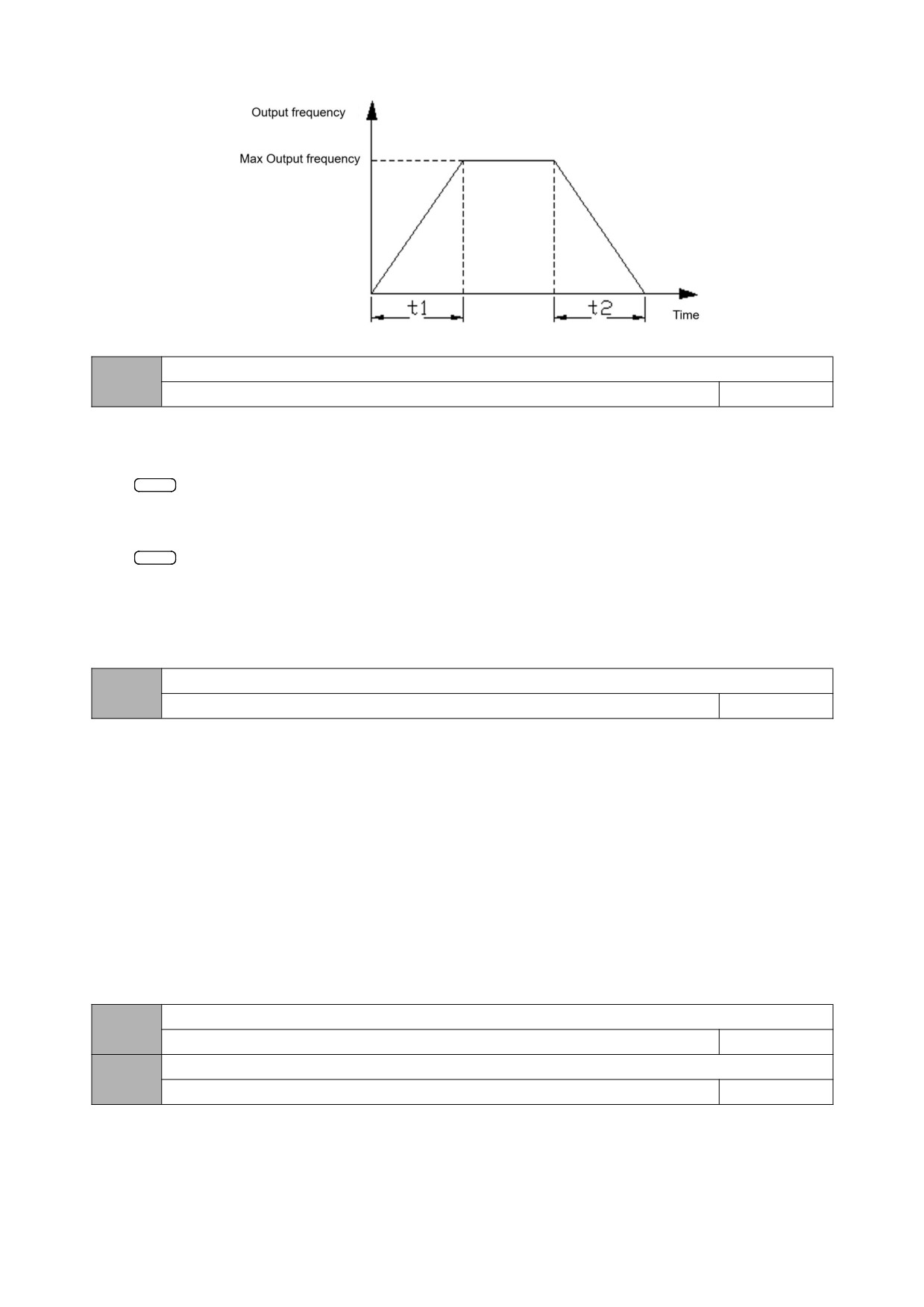
Figure 00-2 Schematic diagram of acceleration time and deceleration time
Rotation direction setting
00.12
0~2
0
0: forward
When this mode is selected, the actual output phase sequence of the inverter is consistent with the system default phase sequence. At this time, the functions of
the keys
RUN
on the panel and the FWD terminal become forward rotation control.
1: Reverse
When this mode is selected, the actual output phase sequence of the inverter will be opposite to the system default phase sequence. At this time, the functions of
the keys
RUN
on the panel and the FWD terminal become reverse control.
2: Reversal is prohibited
In any case, the motor can only run forward. This function is suitable for occasions where reverse operation may bring danger or property damage. Given a reverse
command, the inverter runs at zero speed.
V/F curve setting
00.13
0~2
0
This group of function codes defines the setting mode of the motor's V/F curve to meet the requirements of different load characteristics. According to the definition of
00.13, fixed curves and a custom curve can be selected.
0: linear curve
The linear curve is suitable for ordinary constant torque load, and the output voltage has a linear relationship with the output frequency.
1: Square curve
The square curve is suitable for square torque loads such as fans and water pumps to achieve the best energy saving effect. The output voltage and the output
frequency have a square curve relationship.
2: Multi-point V/F curve (determined by 00.17~00.22)
When 00.13 selects 2, the user can customize the V/F curve through 00.17~00.22, and define the V/F curve by adding (V1, 01), (V2, F2), (V3, F3), and the origin and
maximum frequency points. F curve is suitable for special load characteristics.
Torque boost setting
00.14
0.0~30.0% Motor rated voltage
Model setting
Torque boost cut-off frequency
00.15
0.0~50Hz
15.00
In order to compensate for the low-frequency torque characteristics, some boost compensation can be made to the output voltage. When this function code is set to
0.0%, it is automatic torque boost. When it is set to any value other than 0.0%, it is manual torque boost mode. 00.15 defines the boost cut-off frequency point fz during
manual torque boost, as shown in Figure 00 -4 shown.
34
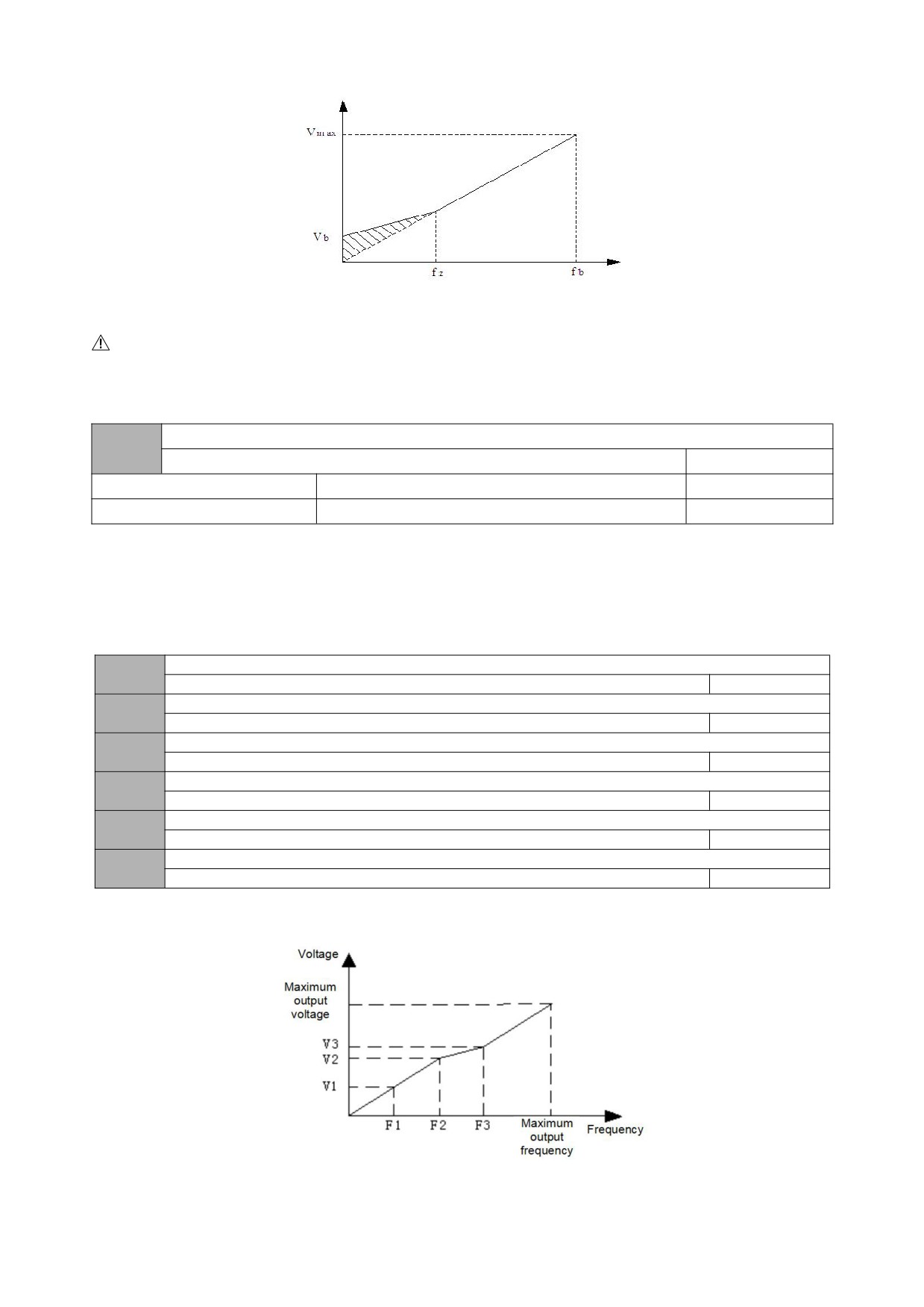
Vb-Manual torque boost
Figure 00-4 Schematic diagram of torque boost
Notice:
1: In the normal V/F control mode, the automatic torque boost mode is invalid.
2: Automatic torque boost is only valid in advanced V/F control mode.
Carrier frequency setting
00.16
1.0~16.0KHz
Model setting
0.4~2.2KW
4.0KHz
1.0~16.0KHz
4.0~5.5KW
3.0KHz
1.0~16.0KHz
This function code is used to set the carrier frequency of the PWM wave output by the inverter. The carrier frequency will affect the noise when the motor is running.
For occasions that require silent operation, the carrier frequency can be appropriately increased to meet the requirements. However, increasing the carrier frequency
will increase the heat generation of the inverter and at the same time increase the electromagnetic interference to the outside world.
When the carrier frequency exceeds the factory setting value, the inverter needs to be derated for use. Generally, the inverter current needs to be derated by about
5% for every 1KHz increase in the download wave.
V/F Frequency value F1
00.17
0.00~Frequency value F2
12.5 Hz
V/F Voltage value V1
00.18
0.0~Voltage value V2
25.0%
V/F Frequency value F2
00.19
Frequency value F1~Frequency value F3
25.0 Hz
V/F Voltage value V2
00.20
Voltage value V1~Voltage value V3
50.0%
V/F Frequency value F3
00.21
Frequency value F2~Motor rated frequency【04.03】
37.5 Hz
V/F Voltage value V3
00.22
Voltage value V2~100.0%*motor rated voltage【04.00】
75.0%
The schematic diagram of voltage and frequency is as follows:
Figure 00-5 Schematic diagram of user setting V/F curve
35
User password
00.23
0~9999
0
The user password setting function is used to prohibit unauthorized personnel from viewing and modifying function parameters.
When setting the user password, enter any non-zero number, press the keyENTER to confirm, and the password will automatically take effect after 3 minutes.
ENTER
When you need to change the password, select the 00.23 function code and press the key
to enter the password verification state. After the password
verification is successful, enter the modification state, enter the new password, and press the keyENTER to confirm, the password change is successful, and the
password will automatically take effect after 3 minutes.
Please keep the password properly. If you forget it, please ask the manufacturer for service.
Frequency display resolution selection
00.24
0~1
0
0:0.1 Hz(0.0~999.9 HZ)
1:1 Hz(0~999 HZ)
Group 01-auxiliary operating parameters
Starting method
01.00
00~12
00
LED units: start mode
0: Start from the starting frequency
Start according to the set starting frequency (01.01).
1: DC braking + starting frequency start
Perform DC braking first (see 01.03), and then start according to mode 0.
2: reserved
LED ten digits: restart mode after power failure or abnormal
0: invalid
When the power is turned on after a power failure, the inverter will not run automatically.
1: Start from the starting frequency
When the power is turned on after a power failure, if the starting conditions are met, the inverter will automatically start to run from the starting frequency point.
Starting frequency
01.01
0.00~50.00Hz
1.00
The starting frequency refers to the initial frequency when the inverter starts. For some systems with relatively large starting torque, setting a reasonable starting
frequency can effectively overcome the problem of starting difficulties.
Starting DC braking current
01.02
0.0~150.0%*Motor rated current
0.0%
Start DC braking time
01.03
0.0~100.0s
0.0
The setting of starting DC braking current is the percentage relative to the rated output current of the inverter.
When the starting DC braking time is 0.0s, there is no DC braking process. The details are shown in the figure below.
36
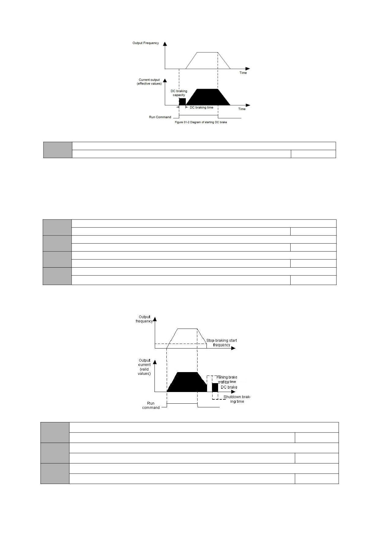
Fig. 01-1 Schematic diagram of starting DC braking
Stop mode
01.04
0~1
0
0: Decelerate to stop
After receiving the stop command, the inverter will gradually reduce the output frequency according to the deceleration time, and stop after the frequency drops
to zero. If the stop DC braking function is valid, after reaching the start frequency of the stop DC braking (according to the 01.05 setting, there may be a waiting time for
the stop DC braking), the DC braking process will be executed and the machine will stop.
1: Free stop
After the inverter receives the stop command, it immediately terminates the output, and the load stops freely according to the mechanical inertia.
Start frequency of DC braking during stop
01.05
0.0~【00.05】upper limit frequency
0.00
Stop DC braking Voltage
01.06
0.0~150.0%* rated Voltage of motor
0.0%
Time for DC braking during stop
01.07
0.0~30.0S
0S
Waiting time for DC braking during stop
01.08
0.0:DC braking does not work
0.1~99.99s
0.0
The set value of the stop DC braking current is the percentage relative to the rated current of the inverter. When the braking time at stop is 0.0s, there is no DC
braking process. As shown below.
Fig. 01-2 Schematic diagram of DC braking at stop
Forward jog frequency
01.09
0.00~【00.05】
10.00
Reverse jog frequency
01.10
0.00~【00.05】
10.00
Jog acceleration time
01.11
0.1~999.9s
Model setting
37
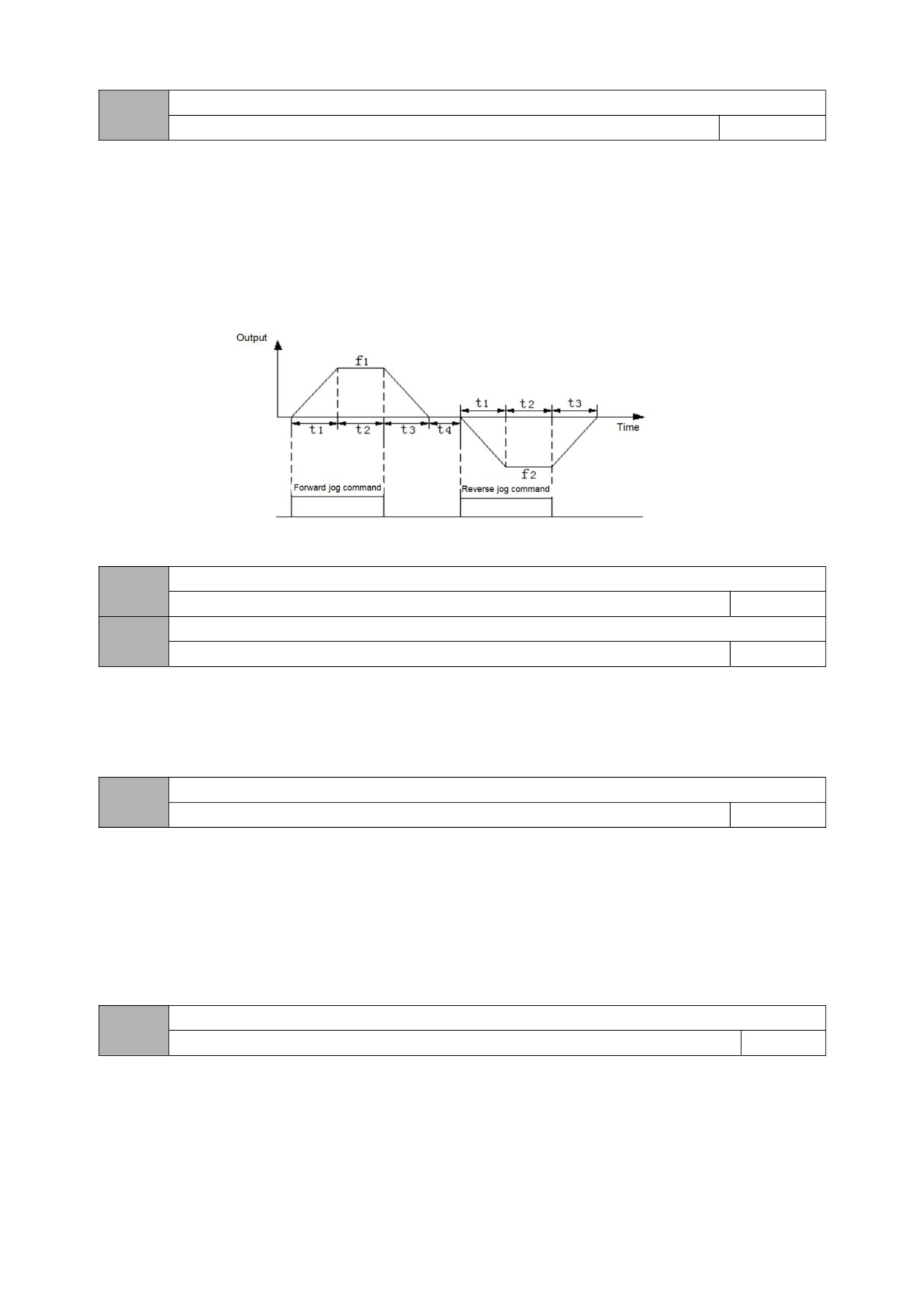
Jog deceleration time
01.12
0.1~999.9s
Model setting
01.09~01.12 define the relevant parameters during jog operation. As shown in Figure 01-3, t1 and t3 are the actual jog acceleration and deceleration time; t2 is
the jog time; f1 is the forward jog operation frequency (01.09); f2 is the reverse jog operation frequency (01.10 ). The actual jog acceleration time t1 is determined
according to the following formula:
t1=01.09*01.11/00.04
In the same way, the actual jog deceleration time t3 can also be determined as follows:
t3=01.10*01.12/00.04
Among them, 00.06 is the maximum output frequency.
Figure 01-3 Jog operation diagram
Jump frequency
01.13
0.0~Upper limit frequency
0.0
Jump range
01.14
0.0~Upper limit frequency
0.0
The above function codes are functions set to make the output frequency of inverter avoid the resonance frequency point of mechanical load. The set frequency of
the inverter can be given by jumping near some frequency points according to the following figure. Its specific meaning is that the frequency of the inverter will never run
stably within the jumping frequency range, but will pass through this range during acceleration and deceleration.
Frequency source combination given method
00.15
0~8
0
0: Potentiometer+digital frequency 1
1: Potentiometer+digital frequency 2
2: Potentiometer +AI
3: Digital frequency 1+AI
4: Digital frequency 2+AI
5: Digital frequency 1+ multi-speed
6: Digital frequency 2+ multi-speed
7: Potentiometer+Multistage Speed
8: AI+PLC (superposition in the same direction)
Programmable operation control (simple PLC operation)
01.16
0000~1221
00000
LED units: PLC enable control
0: invalid
1: Effective
LED ten digits: operation mode selection
0: single loop
After the inverter completes a single cycle, it will stop automatically. At this time, it needs to give the running command again to start. If the running time of a certain
stage is 0, then skip this stage while running and go directly to the next stage. As shown below:
38
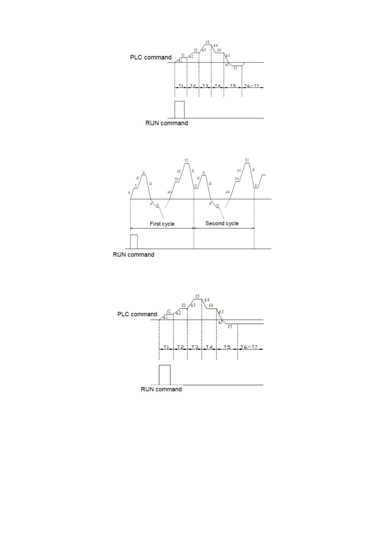
Figure 01-4 Schematic diagram of PLC shutdown after a single cycle
1: Continuous circulation
After the inverter completes a cycle, it will automatically start the next cycle, and will not stop until a stop command is issued. As shown below:
Figure 01-5 PLC continuous cycle diagram
2: Keep the final value after a single cycle
After the inverter completes a single cycle, it automatically maintains the operating frequency and direction of the last segment to operation. As shown below:
Fig. 01-6 The schematic diagram of PLC holding after a single cycle
Hundreds of LEDs: start mode
0: restart from the first segment
Stop during operation (caused by stop command, fault or power failure), and start to run from the first stage after restart.
1: Start from the stage at the moment of shutdown (fault)
If the inverter stops during operation (caused by a stop command, fault or power failure), the inverter will automatically record the running time of the current stage.
After restarting, it will automatically enter this stage and continue to run for the remaining time at the frequency defined in this stage, as shown in the figure below:
39
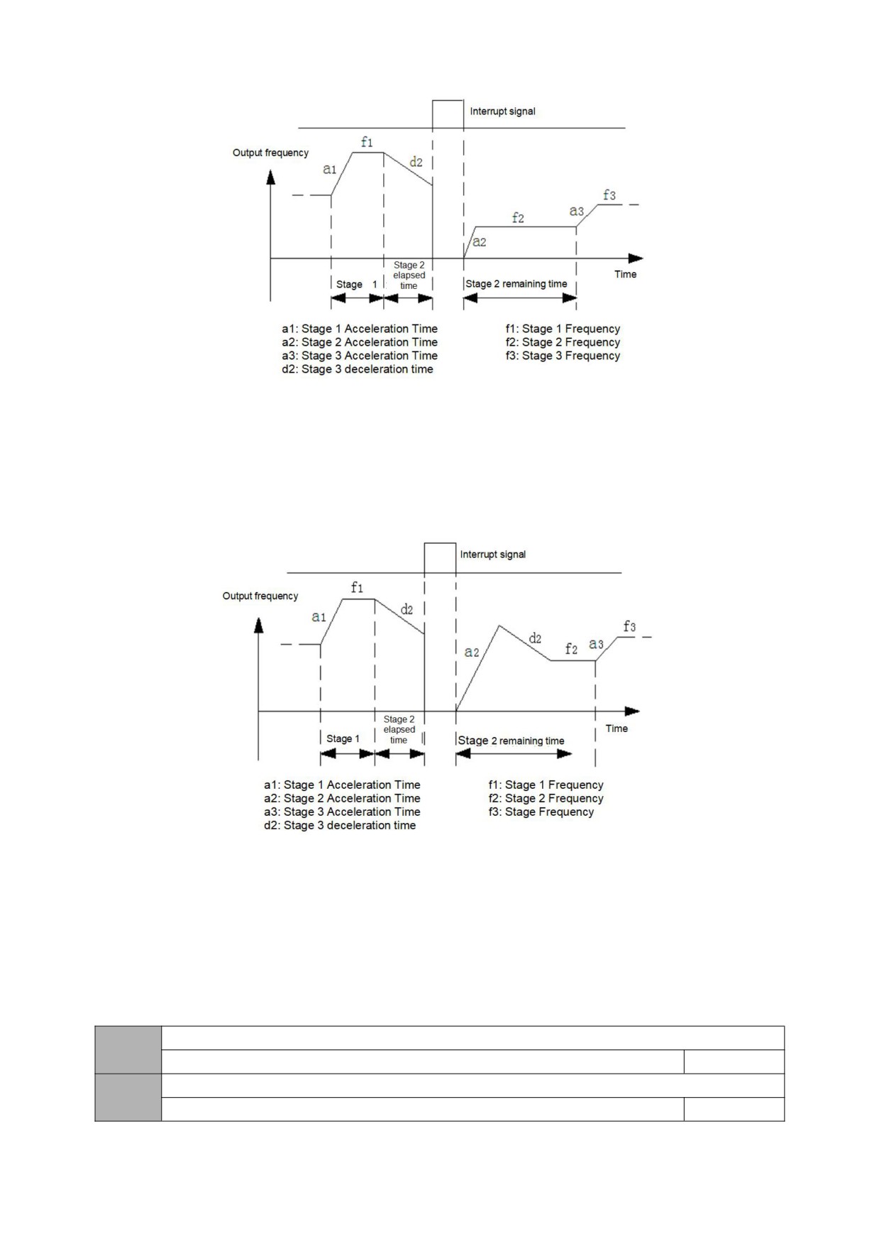
Fig. 01-7 PLC start mode 1
2: Start from the stage and frequency of shutdown (failure) time
In case of shutdown during operation (caused by shutdown command, fault or power failure), the inverter not only automatically records the running time at the
current stage but also records the running frequency at the shutdown time, and then recovers to the running frequency at the shutdown time after starting again, and
the remaining phases of the frequency run, as shown in the following figure:
Fig. 01-8 PLC start mode 2
Thousands of LEDs: power-down storage options
0: do not store
The PLC running state is not memorized when the power is off, and it starts to run from the first stage after power-on.
1: storage
The PLC running status is memorized when the power is off, including the stage at the time of power down, the running frequency, and the running time. Restart
after power-on, it will automatically enter this stage, and continue to run for the remaining time at the frequency defined in this stage.
Multi-speed frequency 1
01.17
-Upper limit frequency ~ +upper limit frequency
5.0
Multi-speed frequency2
01.18
-Upper limit frequency ~ +upper limit frequency
10.0
40
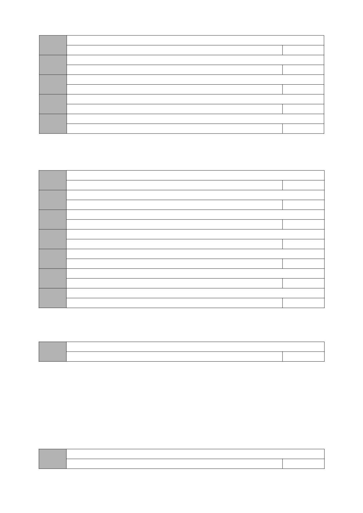
Multi-speed frequency 3
01.19
-Upper limit frequency ~ +upper limit frequency
15.0
Multi-speed frequency 4
01.20
-Upper limit frequency ~ +upper limit frequency
20.0
Multi-speed frequency 5
01.21
-Upper limit frequency ~ +upper limit frequency
25.00
Multi-speed frequency 6
01.22
-Upper limit frequency ~ +upper limit frequency
37.5
Multi-speed frequency 7
01.23
-Upper limit frequency ~ +upper limit frequency
50.0
The sign of multi-speed determines the direction of operation, and negative means operation in the opposite direction. The start-stop command is set by 00.02.
Stage 1 running time (the unit is selected by [01.35], and the default is seconds)
01.24
0.0~999.9 S
10.0
Stage 2 running time (the unit is selected by [01.35], and the default is seconds)
01.25
0.0~999.9 S
10.0
Stage 3 running time (the unit is selected by [01.35], and the default is seconds)
01.26
0.0~999.9 S
10.0
Stage 4 running time (the unit is selected by [01.35], and the default is seconds)
01.27
0.0~999.9 S
10.0
Stage 5 running time (the unit is selected by [01.35], and the default is seconds)
01.28
0.0~999.9 S
10.0
Stage 6 running time (the unit is selected by [01.35], and the default is seconds)
01.29
0.0~999.9 S
10.0
Stage 7 running time (the unit is selected by [01.35], and the default is seconds)
01.30
0.0~999.9 S
10.0
The above function code is used to set the running time of the programmable multi-speed. The 7-segment running time can be set separately by the X-segment
running time.
Stage Select 1 for acceleration and deceleration time
01.31
0000~1111
0000
LED bit: Stage 1 acceleration and deceleration time
0~1
LED ten bits:Stage 2 Acceleration and deceleration time
0~1
LED hundred bits:Stage 3 Acceleration and deceleration time
0~1
LED thousand bits:Stage 4 Acceleration and deceleration time
0~1
Note:
0:Acceleration and deceleration time 1【00.10~00.11】
1:Acceleration and deceleration time 2【01.33~01.34】
Stage Select 2 for acceleration and deceleration time
01.32
0000~1111
0000
41
LED bit: Stage 5 acceleration and deceleration time
0~1
LED ten bits:Stage 6 acceleration and deceleration time
0~1
LED hundred bits:Stage 7 acceleration and deceleration time
0~1
LED thousand bits:Reserved
Acceleration time 2
01.33
0.1~999.9 s
10.0
Deceleration time 2
01.34
0.1~999.9 s
10.0
Two groups of acceleration/deceleration time can be defined, and the acceleration/deceleration time 1 ~ 2 during inverter operation can be selected through
different combinations of control terminals. Please refer to the definition of acceleration/deceleration time terminal function in 02.13~02.17.
Time unit selection
01.35
000~211
000
LED bit: process PID time unit
LED ten bits: simple PLC time unit
LED hundred bits: regular acceleration and deceleration time unit
LED thousand bits: reserved
0: 1 second
1: 1 minute
2: 0.1 second
This function code defines the dimension of acceleration and deceleration time.
Forward and reverse dead time
01.36
0.0~999.9s
0.0
The waiting time for the inverter to transition from forward running to reverse running, or from reverse running to forward running, is t1 as shown in the figure below.
Figure 01-9 Schematic diagram of forward and reverse dead time
Group 02-analog and digital input and output parameters
AI input lower limit Voltage
02.00
0.00V/0.00mA~【02.01】
0.00
42
AI input upper limit Voltage
02.01
【02.00】~10.00V/20.00mA
10.00
AI lower limit corresponding setting
02.02
-100.0%~100.0%
0.0%
AI upper limit corresponding setting
02.03
-100.0%~100.0%
100.0%
02.04
Reserved
Reserved
~02.07
The analog input Signal filtering time constant.
02.08
0.1~5.0s
0.1
The above function codes define the input range of analog input voltage channel AI and its corresponding physical quantity percentage and filter time constant. It
can be selected as voltage/current input through the J5 jumper, and its digital setting can be set according to the relationship of 0~20mA corresponding to 0~10V. The
specific setting should be determined according to the actual situation of the input signal.
The AI input filter time constant is mainly used to filter the analog input signal to eliminate the influence of interference. The larger the time constant, the stronger
the anti-interference ability and the more stable the control, but the slower the response; conversely, the smaller the time constant, the faster the response, but the
weaker the anti-interference ability, the control may be unstable. If the optimal value cannot be determined in practical applications, the value of this parameter should
be adjusted appropriately according to whether the control is stable and the response delay.
Analog input anti-shake deviation limit
02.09
0.00V~10.00V
0.10
When the analog input signal fluctuates frequently near the given value, you can set 02.09 to suppress the frequency fluctuation caused by this fluctuation.
AO multifunctional analog output terminal function selection
02.10
0-5
0
The above function codes determine the corresponding relationship between the multi-function analog output terminal AO and each physical quantity, as shown in
the following table:
Set
Function
AO
Range
0V/0mA~AO upper limit
0~Maximum output frequency
0
Output frequency
2V/4mA~AO upper limit
0~Maximum output frequency
0V/0mA~AO upper limit
0~2 times rated current
1
Output current
2V/4mA~AO upper limit
0~2 times rated current
0V/0mA~AO upper limit
0~Motor synchronous speed
2
Motor speed
2V/4mA~AO upper limit
0~Motor synchronous speed
0V/0mA~AO upper limit
0~1.2 times rated output voltage
3
The output voltage
2V/4mA~AO upper limit
0~1.2 times rated output voltage
0V/0mA~AO upper limit
0V/0mA~10V/20mA
4
AI
2V/4mA~AO upper limit
0V/0mA~10V/20mA
5
Reserved
-
-
AO1 output lower limit
02.11
0.00~10.00V
0.00
AO output upper limit
02.12
0.00~10.00V
10.00V
The above function code defines the corresponding relationship between the output value and the analog output. When the output value exceeds the set maximum
output or minimum output range, it will be calculated as the upper limit output or the lower limit output.
43
Input terminal DI1 function
02.13
0~30
3
Input terminal DI2 function
02.14
0~30
4
Input terminal DI3 function
02.15
0~30
0
Input terminal DI4 function
02.16
0~30
0
Input terminal DI5 function
02.17
0~30
0
0: Reserved
1: Forward jog control
If the terminal is short-circuited with GND, the inverter will run in forward jog mode, which is only valid when 00.02=1.
2: Reverse jog control
If the terminal is short-circuited with GND, the inverter will run in reverse jog mode, which is only valid when 00.02=1.
3: Forward running (FWD)
If the terminal is short-circuited with GND, the inverter will run forward, which is only valid when 00.02=1.
4: Reverse operation (REV)
If the terminal is short-circuited with GND, the inverter will run in reverse, which is only valid when 00.02=1.
5: Three-line operation control
Refer to 02.18 for the function description of operation mode 2, 3, 4 (three-wire control mode 1, 2, 3).
6: Free stop control
This function has the same meaning as the free-running stop defined in 01.04, but here is realized by the control terminal, which is convenient for remote control.
7: External stop signal input (STOP)
This function is used in emergency stop situations, the terminal is short-circuited with GND, and the stop is decelerated by the deceleration time (00.11).
8: External reset signal input (RST)
When a fault occurs in the inverter, the fault can be reset through this terminal. Its function is the same as that of the keySTOP/RESET . This function is valid under
any command channel.
9: External equipment failure normally open input
Through this terminal, the fault signal of the external equipment can be input, which is convenient for the inverter to monitor the fault of the external equipment.
After the inverter receives the external equipment failure signal, it will display "E-EF", that is, the external equipment failure alarm, and the failure signal can adopt the
normally open input mode.
10: Frequency increment command
When the terminal is short-circuited with GND, the frequency will increase. It is valid only when the frequency setting channel is digital setting 2 (terminal
UP/DOWN adjustment).
11: Frequency decreasing instruction
If the terminal is short-circuited with GND, the frequency will decrease. It is valid only when the frequency setting channel is digital setting 2 (terminal UP/DOWN
adjustment).
13: Multi-speed selection S1
14: Multi-speed selection S2
15: Multi-speed selection S3
By selecting the ON/OFF combination of these function terminals, up to 7 speeds can be selected. The details are shown in the following table:
44
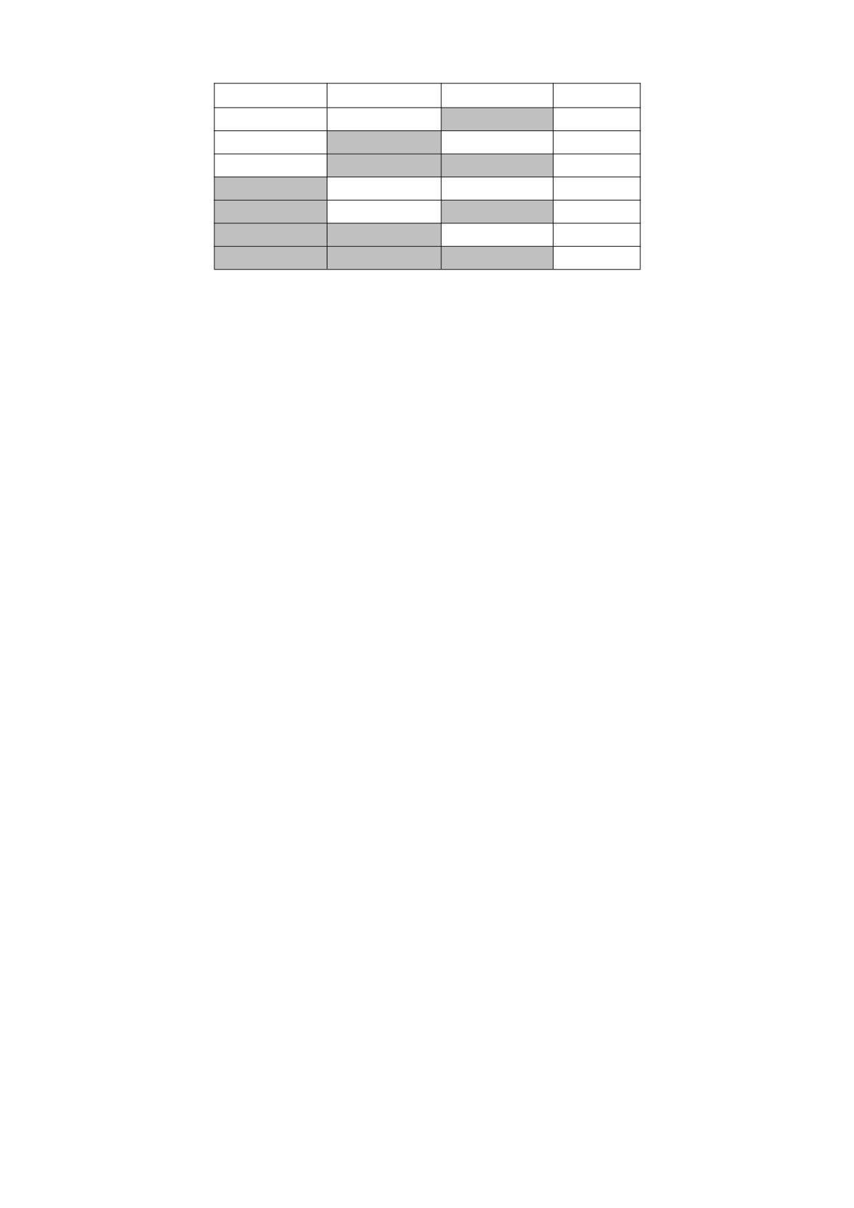
S3
S2
S1
Stage speed
OFF
OFF
ON
1
OFF
ON
OFF
2
OFF
ON
ON
3
ON
OFF
OFF
4
ON
OFF
ON
5
ON
ON
OFF
6
ON
ON
ON
7
16: The run command channel is forced to be a terminal
When this terminal is valid, the running command is forcibly converted from the current channel to terminal control, disconnect the terminal and return to the
previous running command channel.
17: The run command channel is forced to be communication
When this terminal is valid, the running command is forcibly converted from the current channel to communication control, disconnect the terminal, and return to
the previous running command channel.
18: Stop DC braking command
When this terminal is valid, the inverter directly switches to the DC braking state.
19: Frequency switch to AI
When this terminal is valid, the inverter frequency setting switch AI.
20: frequency switch to digital frequency 1
When this terminal is valid, the inverter frequency setting switches to digital frequency 1.
21: frequency switch to digital frequency 2
When this terminal is valid, the inverter frequency setting switches to digital frequency 2.
22:Reserved
23: Counter clear signal
The terminal is short-circuited with GND to clear the internal counter and use it in conjunction with the 24th function.
24: Counter trigger signal
The count pulse input port of the internal counter receives a pulse, the count value of the counter increases by 1 (if the counting mode is down counting, then
decreases by 1), and the maximum frequency of the count pulse is 200 Hz.
25: Timer clear signal
The terminal is short-circuited with GND to clear the internal timer and use it in conjunction with function No. 26.
26: Timer trigger signal
The trigger port of the internal timer.
27: Acceleration and deceleration time selection
By selecting these function terminals to be valid, select the second type of acceleration and deceleration time.
28: Swing frequency pause (stop at the current frequency)
When the terminal is short-circuited with GND, the inverter suspends the swing frequency operation mode, the inverter frequency stops running at the current
frequency; the swing frequency operation continues after this terminal is invalid.
29: Swing frequency reset (return to center frequency)
When this function is selected, whether it is automatic or manual input mode, closing this terminal will clear the wobble frequency status information stored in the
inverter. After disconnecting this terminal, the wobble frequency restarts (if there is a preset frequency, run the preset frequency first).
30: External stop/reset signal input (STOP/RST)
In any control mode (panel control, terminal control, communication control), this terminal can be used to decelerate and stop the inverter.
Use the terminal to perform the fault reset function. It has the same function as the RESET key on the keyboard. Use this function to realize remote fault reset.
45
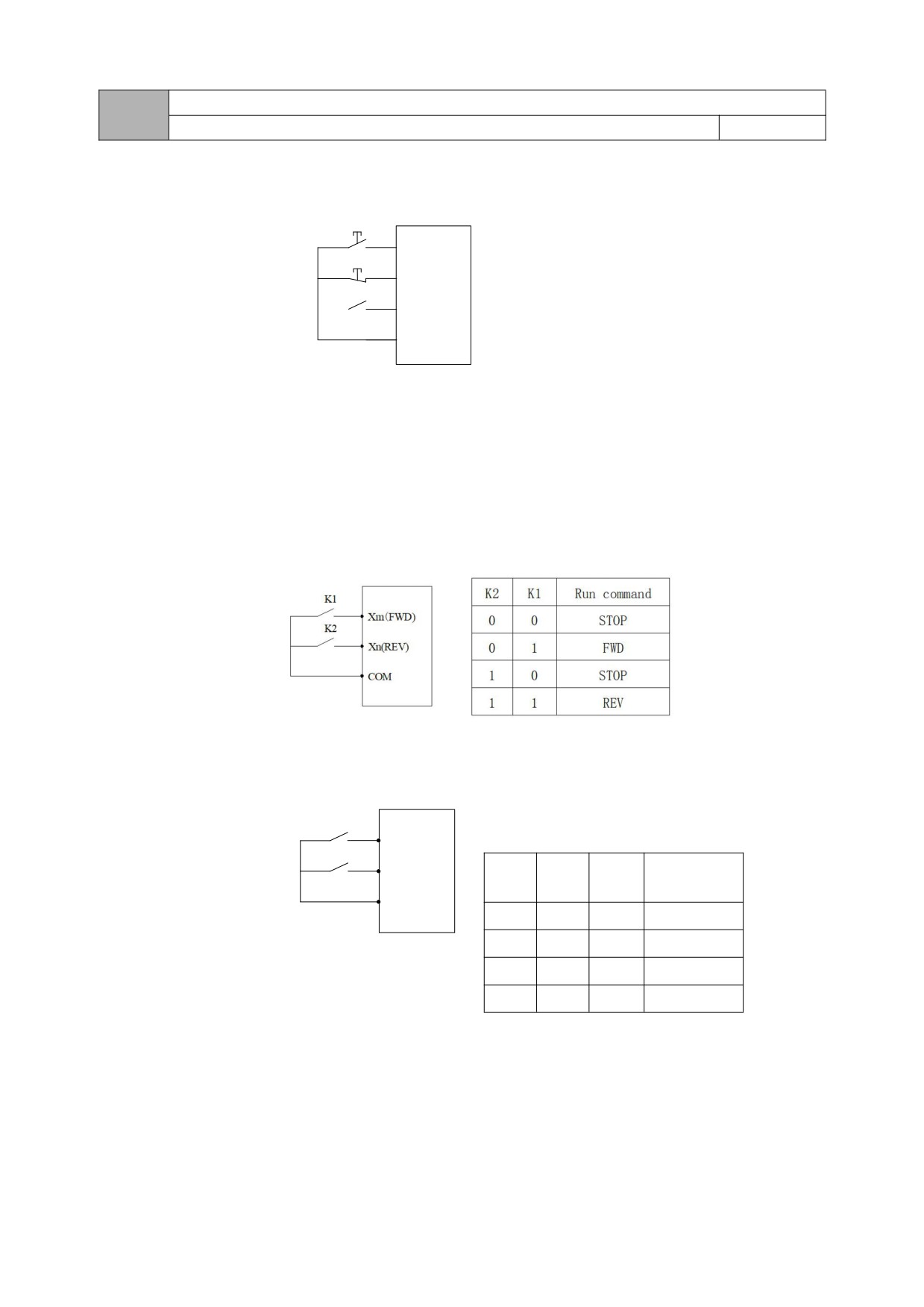
FWD/REV terminal control mode
02.18
0~5
0
This function code defines four different ways to control the operation of the inverter through external terminals.
0: Two-wire control mode 1
Xm: Forward rotation command (FWD), Xn: Reverse rotation command (REV), Xm and Xn represent any two terminals of DI1-DI5 defined as FWD and REV
K1
functions respectively. In this control mode, K1 an
operation and direction of the inverter
Xm(FWD)
K3
Xx
K2
Xn(REV)
COM
Figure 02-1 Schematic diagram of two-wire control mode 1
1: Two-wire control mode 2
Xm: Forward rotation command (FWD), Xn: Reverse rotation command (REV), Xm and Xn represent any two terminals of DI1-DI5 defined as FWD and REV
functions respectively. In this control mode, K1 is the run and stop switch, and K2 is the direction switch.
Figure 2-2 Schematic diagram of two-wire control mode 2
2: Three-wire control mode 1
Xm: Forward rotation command (FWD), Xn: Reverse rotation command (REV), Xx: Stop command, Xm, Xn, Xx represent any 3 terminals of DI1-DI5 defined as
FWD, REV, and three-wire operation control
onnected, the connected K1 and K2 are invalid. When K3 is connected, K1 is
K1
triggered, the inverter rotates forward; K2 is
isconnected, the inverter stops.
Xm(FWD)
K2
Run
Xn(REV)
K3
K2
K1
command
COM
0
0
0
STOP
1
0
1
FWD
1
1
0
REV
0
1
1
STOP
Figure 2-3 Schematic diagram of three-wire control mode 1
3: Three-wire control mode 2
Xm: run command, Xn: run direction selection, Xx: stop command, Xm, Xn, Xx represent any 3 terminals of DI1-DI5 defined as FWD, REV, and three-wire
operation control functions. Before K3 is connected, the connected K1 and K2 are invalid. When K3 is connected, K1 is triggered, and the inverter rotates forward; K2 is
triggered separately, which is invalid; after K1 is triggered to run, K2 is triggered again to switch the running direction of the inverter; K3 is disconnected, and the inverter
stops.
46
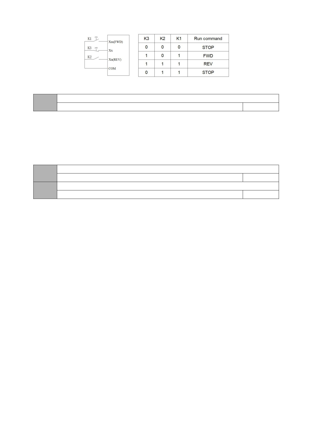
Figure 2-4 Schematic diagram of three-wire control mode 2
Selection of terminal function detection when power on
02.19
0~1
0
0: Terminal running command is invalid when power on
During the power-on process, even if the inverter detects that the run command terminal is valid (closed), the inverter will not start. The inverter can only start when
the terminal is disconnected and closed again.
1: The terminal running command is valid when the power is on
During the power-on process, the inverter detects that the terminal run command terminal is valid (closed), and the inverter can start.
R output setting
02.20
0~17
5
Y Open collector output
02.21
0~17
0
0: Reserved
1: The inverter is ready to run
When the power-on is ready, that is, the inverter has no fault, the bus voltage is normal, the inverter's terminal forbidden to run is invalid, and it can be started
directly by accepting the running command (excluding the inverter's running), the terminal will output an indication signal.
2: The inverter is running
When the inverter is in forward and reverse running state, the output indicator signal.
3: The inverter is running at zero speed
The output frequency of the inverter is 0.00Hz, but it is the indication signal output when it is still in the running state.
4: External fault shutdown
When the inverter has an external fault, the output indicator signal.
5: Inverter failure
When the inverter has a fault, the output indicator signal, refer to the setting of the multi-function input terminal.
6: Frequency/speed arrival signal (FAR)
Refer to 02.24 parameter function description.
7: Frequency/speed level detection signal (FDT)
Refer to the parameter function description of 02.24~02.25.
8: The output frequency reaches the upper limit
When the output frequency of the inverter reaches the upper limit frequency, the output indicator signal.
9: The output frequency reaches the lower limit
When the output frequency of the inverter reaches the lower limit frequency, the output indicator signal.
10: Inverter overload pre-alarm
When the output current of the inverter exceeds the overload pre-alarm level (05.10), the output indicator signal after the alarm delay time (05.11) has elapsed. It is
often used for overload pre-alarm.
11: Timer overflow signal
47
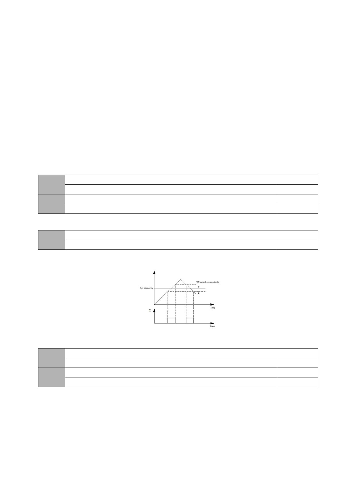
When the actual timing time is ≥07.03 (set timing time), the indicator signal is output.
12: Counter detection signal
When the count detection value is reached, the output indicator signal will be cleared until the count reset value is reached. Please refer to the description of
function code 07.02.
13: Counter reset signal
When the count reset value is reached, an indication signal is output, please refer to the description of function code 07.01.
14: auxiliary motor
Auxiliary motor and terminal function coordination process PID function module can realize simple one-to-two constant pressure water supply function.
15: Forward
When the inverter is in the forward running state, the output indicator signal.
16: Reverse
When the inverter is in the reverse running state, the output indicator signal.
17: Output indication signal when the output frequency drops to the speed detection level
When the output frequency of the inverter drops to the level of speed detection [02.25], an indication signal is output.
R close delay
02.22
0.0~255.0s
0.0
R open delay
02.23
0.0~255.0s
0.0
This function code defines the delay from the change of the state of the relay to the change of the output.
Frequency reaches FAR detection amplitude
02.24
0.0Hz~15.0Hz
5.0
When the output frequency is within the positive and negative detection width of the set frequency, the terminal outputs an effective signal (low level).
Figure 02-5 Schematic diagram of frequency arrival
FDT1 level setting value
02.25
0.0Hz~Upper limit frequency
10.0
FDT lag value
02.26
0.0~30.0Hz
1.0
When the output frequency of the inverter rises and exceeds the set value of FDT level, it outputs a valid signal (open collector signal, low level after the resistance is
pulled up), when the output frequency drops below the FDT signal (set Value- hysteresis value), an invalid signal (high impedance state) is output. As shown below:
48
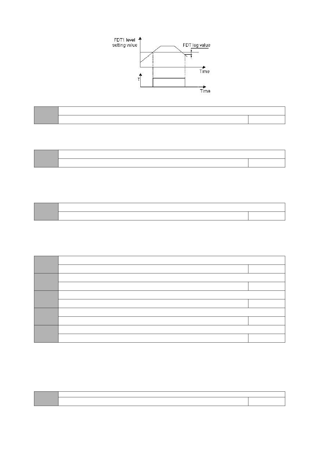
Figure 02-6 Schematic diagram of frequency level detection
UP/DOWN terminal modification rate
02.27
0.0Hz~99.9Hz/s
1.0
The function code is the frequency modification rate when setting the UP/DOWN terminal as frequency set , that is, the UP/DOWN terminal is short-circuited with the
GND terminal for 1s, and the frequency changes.
Input terminal pulse trigger mode setting (DI1~DI5)
02.28
0~1FH
0
0: indicates the electrical level trigger mode
1: indicates the pulse trigger mode
Note:
DI1~DI5 correspond to 1H, 2H, 4H, 8H and 10H in hexadecimal.
Input terminal valid logic setting
(DI1~DI5)
02.29
0~1FH
0
0: indicates positive logic, that is, the DI terminal is connected to GND and GND is valid, and the disconnection is invalid
1: It means anti-logic, that is, DI terminal is not connected to the GND terminal and GND is invalid, and the disconnection is valid
Note:
DI1~DI5 correspond to 1H, 2H, 4H, 8H and 10H in hexadecimal.
DI1 filter coefficient
02.30
0~9999
5
DI2 filter coefficient
02.31
0~9999
5
DI3 filter coefficient
02.32
0~9999
5
DI4 filter coefficient
02.33
0~9999
5
DI5filter coefficient
02.34
0~9999
5
Used to set the sensitivity of the input terminal. If the digital input terminal is susceptible to interference and causes misoperation, this parameter can be increased
to enhance the anti-interference ability, but the sensitivity of the input terminal will be reduced if the setting is too large.
1: represents 2ms scanning time unit
03 group -PID parameters
PID function setting
03.00
0000~2122
1010
49
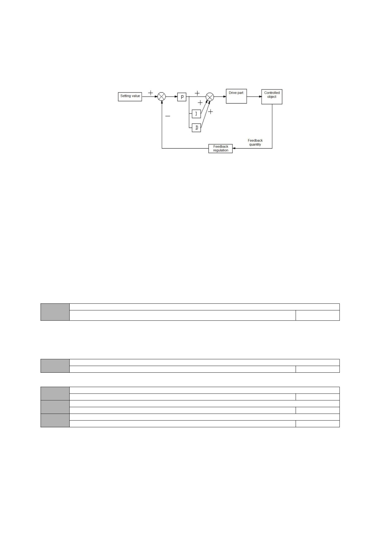
LED bit: PID regulation characteristics
0:invalid
1: positive effect
When the feedback signal is greater than the given quantity of PID, the output frequency of the inverter is required to decrease (that is, reduce the feedback signal).
2: negative effect
When the feedback signal is greater than the given quantity of PID, the output frequency of the inverter is required to rise (that is, reduce the feedback signal).
LED ten bits: PID given input channel
0: keypad potentiometer
PID given quantity is given by potentiometer on the keypad.
1 Number given
PID given quantity is given by numbers and set by function code 03.01.
2 Given pressure (MPa, Kg)
Set the given pressure on 03.01 and 03.18.
LED hundred digits: PID feedback input channel
0: AI
1: Reserved
LED thousand bits: PID sleep selection
0: invalid
1: normal sleep
Specific parameters such as 03.10 ~ 03.13 should be set in this method.
2. Disturbed sleeping
The parameter setting is the same as when the sleep mode is selected as 0. If the PID feedback value is within the range of the set value of 03.14, the sleep
delay time will be maintained and then the disturbance sleep will be entered. When the feedback value is less than the wake-up threshold (PID polarity is positive),
wake up immediately.
Given a numerical setting
03.01
0.0~100.0%
0.0
When analog feedback is used, this function code realizes the setting of the closed-loop control setting with the operation panel. This function is valid only when
the closed-loop setting channel selects the digital setting (the tens place of 03.00 is 0).
Example: In the constant pressure water supply closed-loop control system, the setting of this function code should fully consider the relationship between the
range of the remote pressure gauge and its output feedback signal. For example, the range of the pressure gauge is 0~10MPa, corresponding to 0~10V voltage
output. We need a pressure of 6MPa, then the given digital quantity can be set to 6.00V, so that when the PID adjustment is stable, the required pressure is 6MPa.
Feedback channel gain
03.02
0.01~10.00
1.00
When the feedback channel is inconsistent with the set channel level, this function can be used to adjust the gain of the feedback channel signal.
Proportional gain P
03.03
0.01~5.00
2.00
Integration time Ti
03.04
0.1~50.0s
1.0
Derivative time Td
03.05
0.1~10.0s
0.0
Proportional gain (Kp):
The adjustment intensity of the whole PID regulator is determined by this. And the greater the P is, the greater the adjustment intensity is. But if in too large state,
there is easy to produce oscillation.
When the feedback deviates from the set value, the deviation and output become the regulating value of proportion. If the deviation is constant, the regulating
value is also constant. Proportional adjustment can quickly show out the feedback changes, but it is impossible to achieve error-free control by proportional control
alone. The larger the proportional gain is, the faster the adjustment speed of the system will be, but if too large, oscillation will occur. The adjustment method is to set
the integration time for a longer time, and the differentiation time for zero, then use proportional control to make the system run. With changing the size of the given
quantity, it can observe the stable deviation (static difference) between the feedback signal and the set value. If the static difference changes in the direction of the set
value (for example, if the set value is increased and the feedback value is always less than the set value after the system is stable), then increasing the proportional
gain continues. Otherwise reduce the proportional gain, and repeat the above process until the static difference is relatively small (It's hard to make it without any static
errors)
50
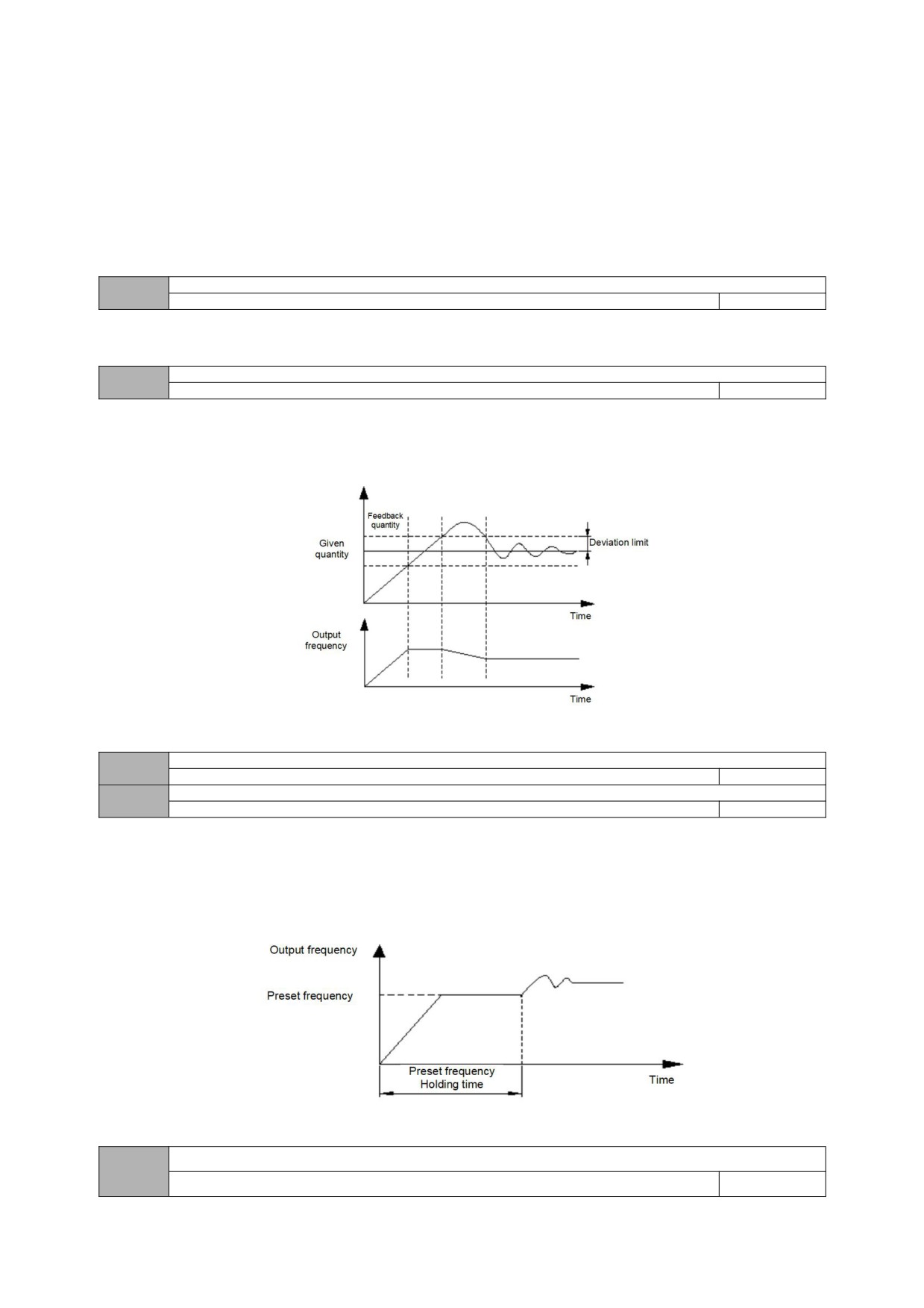
Integral time (ti):
Determine the speed of PID regulators to do the integral adjustment of deviation.
When the feedback deviates from the set value, the output adjustment value need to continuously accumulate. And if the deviation persists, the adjustment value
continuously increases until there is no deviation. Integral regulator can validly eliminate static difference. If the integral regulator is too strong, there will be repeated
overshoot, which will make the system oscillate. Generally, the adjustment of integration time parameters is from large to small, and the integration time is gradually
adjusted, while the effect of system adjustment is observed,all until the stable speed of the system meets the requirements.
Differential time (Td):
Determine the strength of PID regulator to adjust the rate of deviation change.
When the feedback changes with the set deviation, the rate of deviation change and output become the regulating value of proportion, which is only related to the
direction and magnitude of deviation change, but has nothing to do with the direction and magnitude of deviation itself. when the feedback signal changes, the function
of derivative adjustment is to adjust according to the changing trend of it, so as to restrain the change of it. Please use derivative regulator with caution, because
derivative regulator is easy to amplify the interference of the system, especially the interference from large changing frequency.
Sampling period T
03.06
0.1~10.0s
0.0
The larger the sampling period, the slower the response, but the better the interference signal suppression effect, so it is generally unnecessary to set it.
Deviation limit
03.07
0.1~20.0%
0.0
The deviation limit is the ratio of the absolute value of the deviation between the system feedback quantity and the given quantity to the given quantity. When the
feedback quantity is within the deviation limit, the PID adjustment will not operate. As shown in the figure below, setting a reasonable deviation limit can prevent the
system from reaching the target Frequent adjustment near the value will help improve the stability of the system.
Figure 03-2 Schematic diagram of deviation limit
Closed loop preset frequency
03.08
0.0 ~upper limit frequency
0.0
Preset frequency holding time
03.09
0.0~999.9s
0.0
This function code defines the frequency and running time of the inverter before the PID is put into operation when PID control is valid. In some control systems, in
order to make the controlled object reach a predetermined value quickly, the inverter is set according to this function code to force a certain frequency value of 03.08
and a frequency holding time of 03.09 to be output. That is, when the control object is close to the control target, the PID controller is put in to improve the response
speed. As shown below:
Figure 03-2 Schematic diagram of closed-loop preset frequency operation
Sleep threshold coefficient
03.10
0.0~150.0%
100.0
51
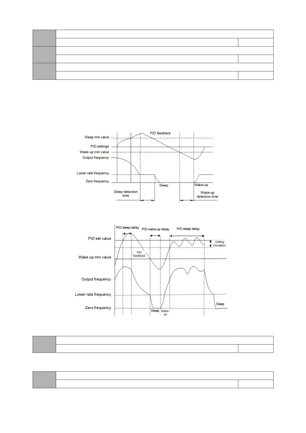
Awakening threshold coefficient
03.11
0.0~150.0%
90.0
Sleep delay time
03.12
0.0~999.9s
1.0
Wake delay time
03.13
0.0~999.9s
1.0
03.10 defines the feedback limit when the inverter enters the sleep state from the working state. If the actual feedback value is greater than the set value, and the
frequency of the inverter output reaches the lower limit frequency, the inverter will enter the sleep state (that is, running at zero speed) after the delay waiting time
defined in 03.12.
03.11 defines the feedback limit of the inverter from the sleep state to the working state. When the PID polarity is selected as the positive characteristic, if the actual
feedback value is less than the set value (or when the PID polarity is selected as the negative characteristic, if the actual feedback value is greater than the set value),
the inverter passes the defined value of 03.13 After delaying the waiting time, it leaves the sleep state and starts to work.
Figure 03-3 Schematic diagram of the first normal sleep mode
Figure 03-4 Schematic diagram of the second disturbed sleep mode
Deviation between feedback and set pressure when entering sleep
03.14
0.0~999.9s
1.0
This function parameter is only valid for disturbance sleep mode
Delay time of burst detection
03.15
0.0~130.0s
0.0
52
When the feedback pressure is greater than or equal to this set value, the pipe burst fault "EPA0" will be reported after the 03.15 burst delay. When the feedback
pressure is less than this set value, the pipe burst fault "EPA0" will be automatically reset; the threshold is the given pressure Percentage.
High pressure detection threshold
03.16
0.0~200.0%
150.0%
Low pressure detection threshold
03.17
0.0~200.0%
50.0%
When the feedback pressure is greater than or equal to 03.16, the explosion failure “EPA0” will be reported after the explosion delay at 03.15, and when the
feedback pressure is less than this set value, the explosion failure “EPA0” will automatically reset; The threshold is a percentage of the given pressure.
When the feedback pressure is less than 03.17, the explosion failure “EPA0” will be reported after the explosion delay at 03.15, and when the feedback pressure
is greater than or equal to this set value, the explosion failure “EPA0” will automatically reset; The threshold is a percentage of the given pressure.
Measurement range of sensors
03.18
0.00~99.99 (MPa、Kg)
10.00MPa
Set the maximum range of the sensor
04 group -advanced functions parameters
Motor rated voltage
04.00
0~500V
Model setting
Motor rated current
04.01
0.1~999.9A
Model setting
Motor rated speed
04.02
0~9999RPM
Model setting
Motor rated frequency
04.03
1.0~999.9Hz
Model setting
The above function codes must be set according to the motor nameplate parameters. Please configure the corresponding motor according to the power of the
inverter. If the power difference is too large, the control performance of the inverter will be significantly reduced.
Motor stator resistance
04.04
0.001~20.000Ω
Model setting
Motor no-load current
04.05
0.1~【04.01】
Model setting
The above are the parameters of the asynchronous motor. These parameters are generally not on the motor nameplate and need to be automatically tuned by
the inverter.
If it is not possible to tune the asynchronous motor on site, you can enter the corresponding function code above according to the parameters provided by the
motor manufacturer.
AVR function
04.06
0~2
0
0: invalid
1: the whole process is effective
2: invalid only when decelerating
AVR is the function of automatic voltage adjustment. When there is a deviation between the input voltage of the inverter and the rated value, this function is used
to keep the output voltage of the inverter constant to prevent the motor from working in an overvoltage state. This function is invalid when the output command voltage
is greater than the input power voltage. In the deceleration process, if the AVR does not act, the deceleration time is short, but the running current is large; the AVR acts,
the motor decelerates smoothly, the running current is small, but the deceleration time is longer.
53
Cooling fan control
04.07
0~1
0
0: Automatic control mode
1: runs all the time during power on
Automatic fault reset times
04.08
0~10
0
Automatic fault reset interval
04.09
0.5~25.0s
3.0
After a fault occurs during operation, the inverter stops output and displays the fault code. After the reset interval set by 04.09, the inverter automatically resets the
fault and restarts operation according to the set starting mode.
The number of automatic fault resets is set by 04.08. When the fault reset times is set to 0, there is no automatic reset function and can only be reset manually.
When 04.08 is set to 100, it means that the number of times is unlimited, that is, countless times.
For IPM faults, external device faults, etc., the inverter does not allow self-reset operation.
Energy consumption braking starting voltage
04.10
220V:340~380V
360V
Model setting
380V:660~760V
680V
Energy consumption braking action ratio
04.11
10~100%
100%
If the internal DC bus voltage of the frequency inverter is higher than the starting voltage of energy consumption braking, the built-in braking unit will act. If a
braking resistor is connected at this time, the voltage energy raised inside the frequency inverter will be released through the braking resistor, and the DC voltage will
fall down.
Over modulation function selection
04.12
0~1
0
0: invalid
1: valid
The over-modulation function means that the inverter increases the output voltage by adjusting the utilization rate of the bus voltage. When the over-modulation is
effective, the output harmonics will increase. If long-term low-voltage and heavy-load operation or high-frequency (over 50HZ) operating torque is insufficient, this
function can be turned on.
PWM mode
04.13
0~2
0
0: full frequency seven bands
The current output is stable, and the full-band power tube generates a lot of heat.
1: Full frequency five bands
The current output is stable, and the power tube generates a small amount of heat
2: Seven segments to five segments
The current output is stable, the low-frequency power tube heats up more, and the high-frequency power tube heats up less.
Slip compensation coefficient
04.14
0~200%
100%
After the asynchronous motor is loaded, the speed will decrease. The use of slip compensation can make the motor speed close to its synchronous speed, so
that the motor speed control accuracy is higher. This coefficient is only for ordinary V/F mode.
Slip compensation mode
04.15
0~1
0
0: invalid
1: low frequency compensation
54
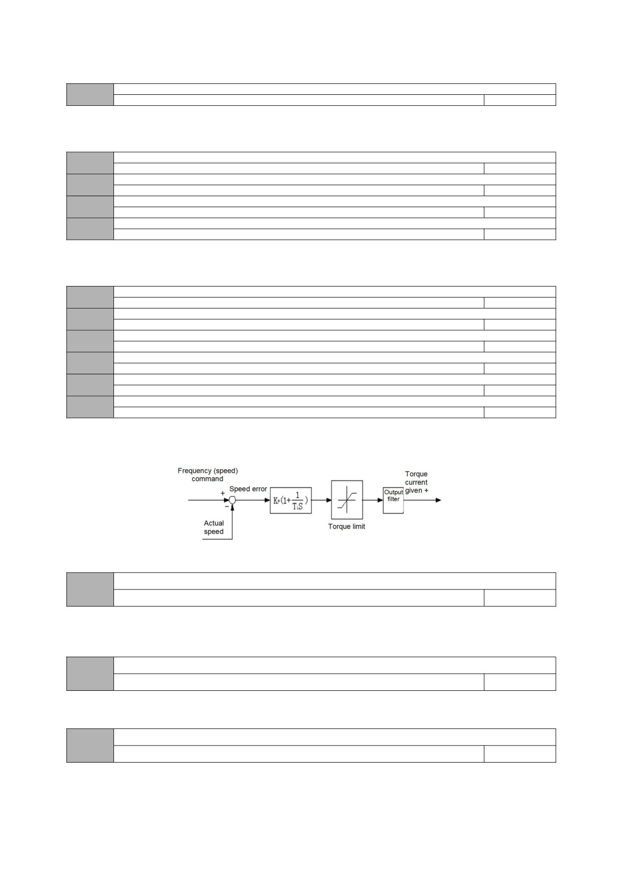
Note: This parameter is only valid for advanced V/F.
Self-learning of motor parameters
04.16
0~1
0
0: invalid
1: Static self-learning (STAR is displayed immediately when it is started. After finished, END is displayed and disappears after 1s
Motor rated Power
04.17
0.0~2000.0KW
Model setting
Rotor resistance of motor
04.18
0.00~200.00Ω
Model setting
Inductance of stator and rotor of motor
04.19
0.00~200.00mH
Model setting
Mutual inductance between stator and rotor of motor
04.20
0.00~200.00mH
Model setting
After the rated power of the motor is changed to 04.17, 04.01, 04.02, 04.04, 04.05, 04.18 ~ 04.20 are automatically updated as the default parameters of the
motor with corresponding power.
Speed loop 1 Proportional gain
04.21
1~100
30
Speed loop 1 Integral time
04.22
0.01~10.00S
0.50
Low frequency switching point
04.23
0.0~10.0Hz
5.0
Speed loop 2 Proportional gain
04.24
1~100
20
Speed loop 2 Integral time
04.25
0.01~10.00S
1.00
High frequency switching point
04.26
【04.23】~320.0Hz
10.0
In vector control mode, the speed response characteristics of vector control are changed by setting the proportional gain p and integration time i of the speed
regulator.
The composition of the speed regulator (ASR) is shown in Figure F4-1. In the figure, KP is the proportional gain P, TI is the integral time I
Fig. 04 -1 Simplified diagram of speed regulator
Vector Slip compensation
04.27
50%~200%
100
In vector control mode, this parameter is used to adjust the speed stability accuracy of the motor. When the motor is overloaded and the speed is low, increase this
parameter, otherwise decrease this parameter.
Speed loop filter time constant
04.28
0.000~1.000S
0.010
Set the speed loop filtering time
Speed loop torque limit
04.30
0.0% ~ 200.0%
150%
The set value is a percentage of the rated current of the motor
55
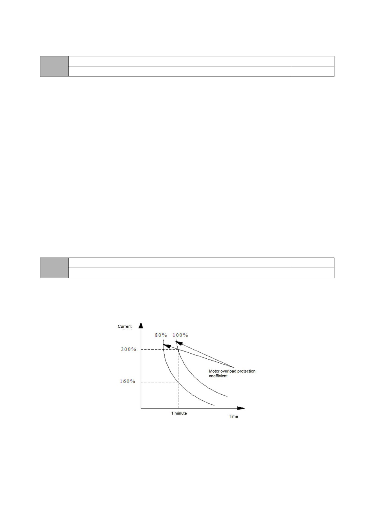
05 Group- Protective Function parameters
Protection settings
05.00
0000~1211
0001
LED unit: motor overload protection option
0: invalid
There is no motor overload protection (use with caution).
1: Valid
As the heat dissipation effect of ordinary motors becomes worse at low speed, the corresponding motor thermal protection value should also be adjusted
appropriately. The low-speed compensation feature mentioned here is just
It is to lower the overload protection threshold of the motor whose operating frequency is lower than 30Hz.
LED Ten bits: PID feedback disconnection protection
0: invalid
1: protection action and free stop
LED hundred bits: 485 communication failure handling
0: protection action and free stop
1: alarm but maintain the status operation;
2: alarm and stop in the set way
LED thousand bits: Oscillation Suppression
0: invalid
1: valid
When the oscillation suppression is effective, the PWM mode is forced to five-stage.
Motor overload protection coefficient
05.01
30%~110%
100%
In order to implement effective overload protection for different types of load motors, it is necessary to reasonably set the overload protection coefficient of the
motor and limit the maximum current value that the inverter can output. The motor overload protection factor is the percentage of the rated current value of the motor to
the rated output current value of the inverter.
When the inverter drives a motor with a matching power level, the motor overload protection coefficient can be set to 100%. As shown below:
Figure 05-1 Motor overload protection curve
When the capacity of inverter is larger than that of motor, in order to implement valid overload protection for load motors of different specifications, it is necessary to
set the overload protection coefficient of motor reasonably as shown in the following figure:
56
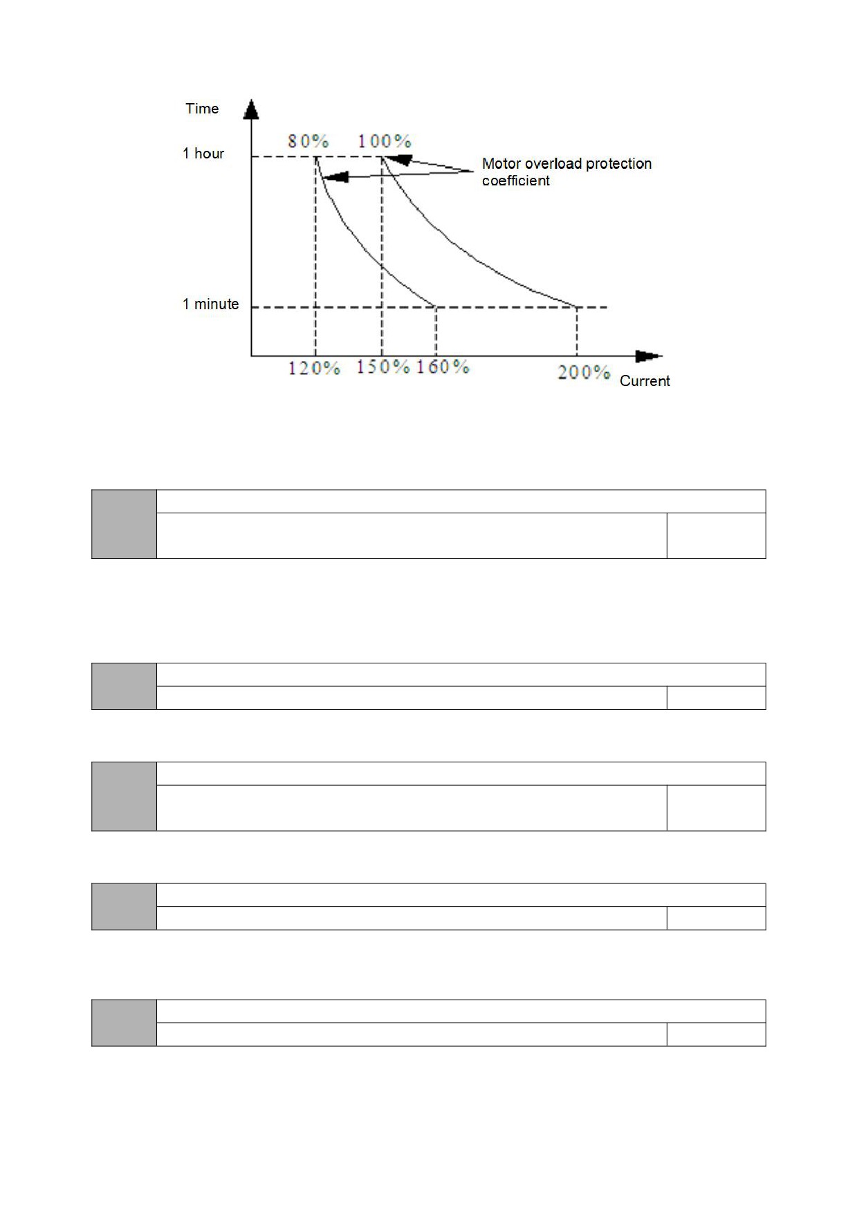
Figure 5-2 Schematic diagram of motor overload protection coefficient setting
The motor overload protection coefficient can be determined by the following formula:
Overload protection coefficient of motor = maximum allowable load current/rated output current of inverter × 100%
Generally, the maximum load current refers to the rated current of the load motor. Adjustment of protection value in line.
Undervoltage protection level
05.02
220V:50~280V
180V
Model setting
380V:50~480V
360V
This function code specifies the allowable lower limit voltage of the DC bus when the inverter is working normally.
When the grid voltage is too low, the output torque of the motor will drop. For constant power loads and constant torque loads, too low grid voltage will increase the
input and output current of the inverter, thereby reducing the reliability of the inverter's operation. Therefore, when running for a long time under low grid voltage, the
inverter power needs to be derated for use.
Voltage limiting factor during deceleration
05.03
0:0FF,1~255
1
This parameter is used to adjust the ability of the inverter to suppress overvoltage during deceleration.
Overvoltage limit level
05.04
220V:350~400V
375V
Model setting
380V:660~850V
700V
The overvoltage limit level defines the operating voltage of the voltage stall protection.
Current limiting coefficient during acceleration
05.05
0:OFF,1~99
10
This parameter is used to adjust the inverter's ability to suppress overcurrent during acceleration. During acceleration, the greater the value, the stronger the ability
to suppress overcurrent.
Current limiting coefficient during constant speed
05.06
0:OFF,1~99
0
This parameter is used to adjust the ability of inverter to restrain overcurrent in the process of constant speed.
57
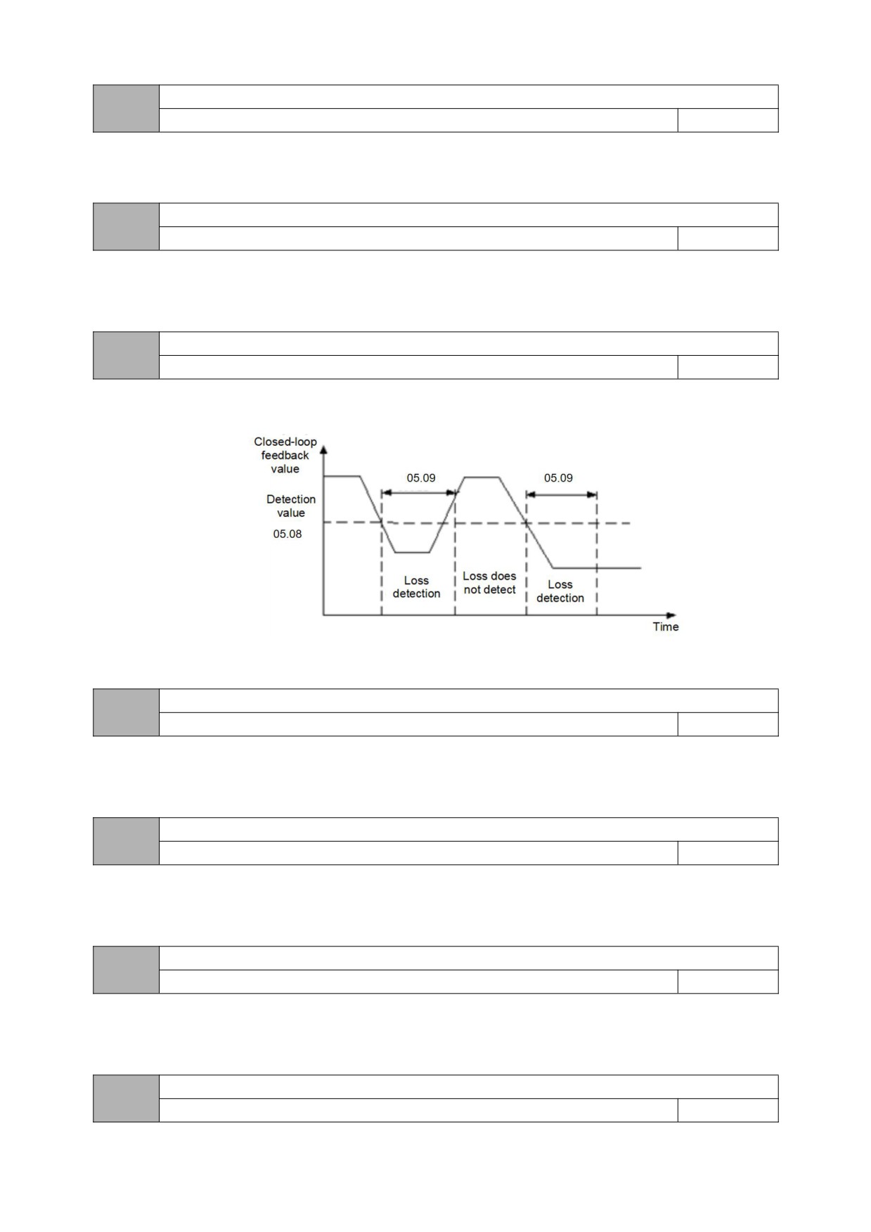
Current limiting level
05.07
50%~200%
160%
The current limiting level defines the current threshold of automatic current limiting operation, and its set value is the percentage relative to the rated current of the
inverter.
Feedback disconnection detection value
05.08
0.0~100.0%
0.0%
This value is the percentage of PID given quantity. When the feedback value of PID is continuously less than the feedback disconnection detection value, the
inverter will make corresponding protection actions according to the setting of 05.00, and it will be invalid when 05.08=0.0%.
Feedback disconnection detection time
05.09
0.1~999.9S
10.0s
Delay time before protection action after feedback disconnection.
Figure 05-3 Timing diagram of closed-loop feedback loss detection
Inverter Overload pre-alarm level
05.10
0~150%
120%
The overload pre-alarm mainly monitors the overload condition of the inverter before the overload protection is activated. The overload pre-alarm level defines
the current threshold of the overload pre-alarm action, and its set value is the percentage relative to the rated current of the inverter.
Inverter Overload pre-alarm delay
05.11
0.0~15.0s
5.0s
The overload pre-alarm delay defines the delay time from the inverter output current continuously greater than the overload pre-alarm level (05.10) to the output
of the overload pre-alarm signal.
JOG priority enable
05.12
0~1
0
0: invalid
1: when the inverter is running, the jog priority is the highest
Oscillation suppression coefficient
05.13
0~200
30
58
Amplitude suppression coefficient
05.14
0~12
5
The Lower limit frequency of oscillation suppression
05.15
0.0~【05.16】
5.0Hz
The upper limit frequency of oscillation suppression
05.16
【05.15】~【00.05】
45.0Hz
In case of motor oscillation, it is necessary to set the effective value of 05.00 thousand bits, turn on the oscillation suppression function, and then adjust it by
setting the oscillation suppression coefficient. In general, the oscillation amplitude is large, so it is unnecessary to set the oscillation suppression coefficient of 05.13,
05.14 ~ 05.16; In case of special occasions, they should be used together from 05.13~05.16.
Selection of wave-by-wave current limit
05.17
000~111
011
LED bit:In acceleration
0:invalid
1:valid
LED ten bits:In deceleration
0:invalid
1:valid
LED hundred-bits: In constant speed
0:invalid
1:valid
LED Thousand bits:Reserved
Output phase lost protection detection coefficient
05.18
0.00~20.00
2.00
When the ratio of the maximum value to the minimum value in the three-phase output current is greater than this coefficient and the duration exceeds 6 seconds,
the frequency inverter reports the output current imbalance fault EPLI;; Output open-phase protection is invalid when 05.18=0.00.
Frequency drop coefficient of instantaneous power failure
05.19
0:the instantaneous stop function is invalid
0
1~9999
Instantaneous power down loss frequency reduction voltage point
05.20
220V:180~330V
250V
Model setting
380V:300~550V
450V
If the inverter bus voltage drops below 05.20* rated bus voltage, and the instantaneous stop control is valid, the instantaneous stop starts to act.
06 group: communication parameters
Local Address
06.00
0~247
1
59
0:Broadcast address.
1~247:Slave
MODBUS communication configuration
06.01
0000~0322
0000
LED bit:baud rate selection
0:9600BPS
1:19200BPS
2:38400BPS
This function code is used to define the data transmission rate between the host computer and the inverter. The baud rate set by the host computer and the
inverter should be the same, otherwise the communication cannot be carried out. The larger the baud rate setting, the faster the data communication. Setting the
conference too much affects the stability of communication.
LED ten bits:data format
0:no parity
1:even parity check
2:Odd Parity Check
The data format set by the host computer and the inverter should be consistent, otherwise normal communication will not be possible.
Hundreds of LEDs: Communication response method
0: normal response
1: Only respond to the slave address
2: No response
3: The slave does not respond to the free stop command of the master in the broadcast mode
Thousands of LEDs: reserved
Communication timeout check-out time
06.02
0.1~100.0s
10.0s
If the machine does not receive the correct data signal within the time interval defined by this function code, then the machine thinks that the communication has
failed, and the frequency inverter will decide whether to protect or maintain the current operation according to the setting of the communication failure action mode;
When this value is set to 0.0, RS485 communication timeout detection is not performed.
local device response delay time
06.03
0~200ms
5ms
This function code defines the intermediate time interval between receiving the data frame of the inverter and sending the response data frame to the upper
computer. If the response time is less than the system processing time, the system processing time shall prevail.
Proportional linkage coefficient
06.04
0.01~10.00
1.00
This function code is used to set the weight coefficient of frequency instruction received by inverter as slave through RS485 interface, and the actual operating
frequency of this machine is equal to the value of this function code multiplied by the value of frequency setting instruction received through RS485 interface. In the
linkage control, this function code can set the ratio of operating frequency of multiple inverters.
Multi-vendor agreement selection (reserved)
06.05
0~3
0
60
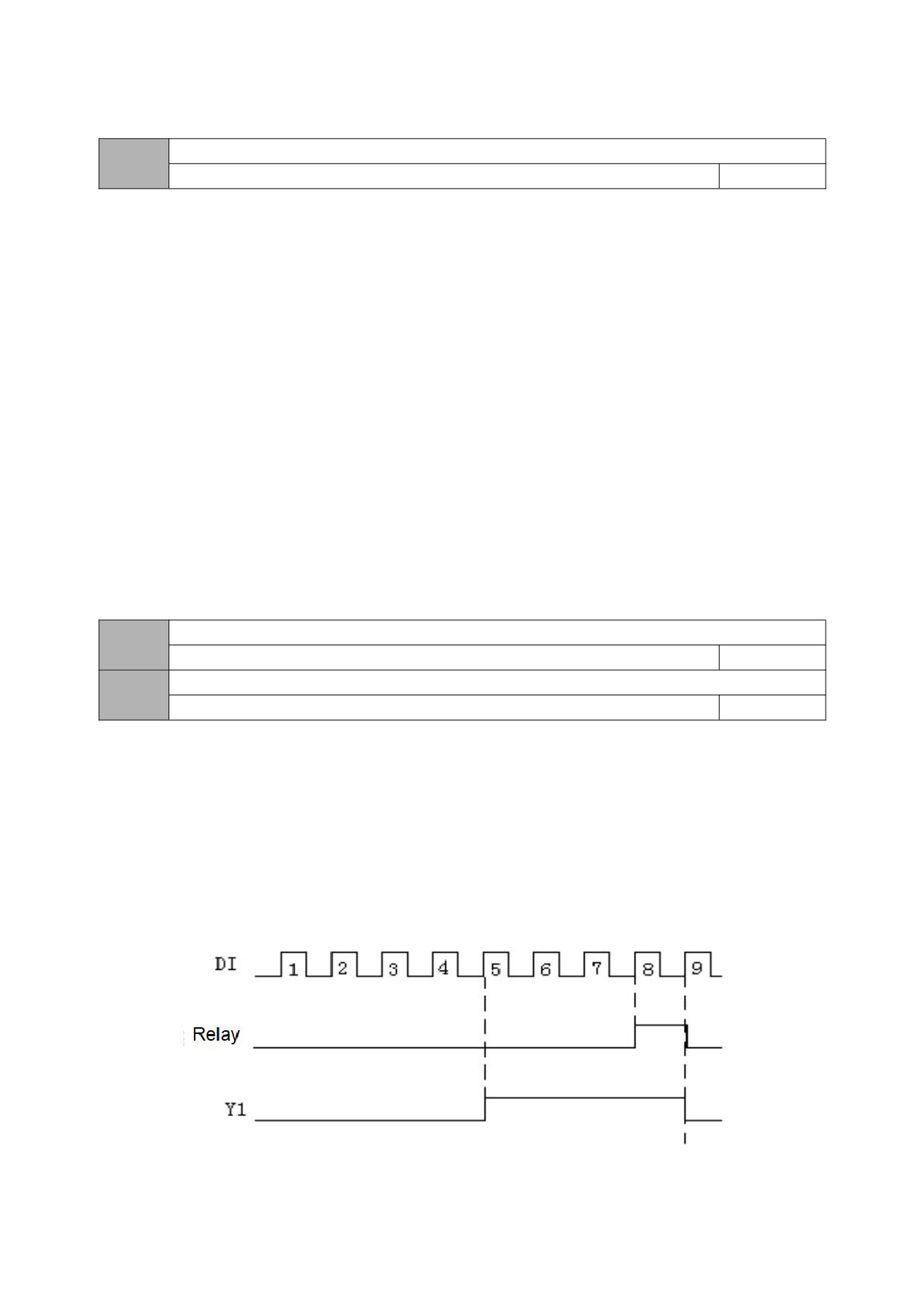
07 Group- supplementary Function parameters
Counting and timing mode
07.00
000~303
103
LED bit: count arrival processing
0: One-cycle counting, stop output
1: One-cycle counting, continue to output
2: Cycle counting, stop output
3: Cycle counting, continue to output
When the count value of the counter reaches the value set by the function code 07.01, the inverter will execute the corresponding action.
LED ten bits: Reserved
LED hundred bits: timing arrival processing
0: One-cycle counting, stop output
1: One-cycle counting, continue to output
2: Cycle counting, stop output
3: Cycle counting, continue to output
When the timer's time reaches the value set by function code 07.03, the inverter will execute the corresponding action.
LED thousand bits: reserved
The counter reset value setting
07.01
【07.02】~9999
1
Setting of counter detection value
07.02
0~【07.01】
1
This function code defines the counting reset value and detection value of the counter. When the count value of the counter reaches the value set by the function
code 07.01, the corresponding multi-function output terminal (counter reset signal output) outputs an effective signal, and the counter is cleared.
When the count value of the counter reaches the value set by the function code 07.02, an effective signal is output at the corresponding multi-function output
terminal (counter detection signal output). If it continues to count and exceeds the value set by function code 07.01, when the counter is cleared, the output valid signal
is cancelled.
As shown in the figure below: Set the programmable relay output as the reset signal output, the open collector output Y as the counter detection output, 07.01 as 8,
and 07.02 as 5. When the detection value is "5", Y outputs an effective signal and keeps it; when it reaches the reset value "8", the relay outputs an effective signal with
a pulse period and clears the counter. At the same time, Y and the relay cancel the output signal.
Figure 07-1 Schematic diagram of counter reset setting and counter detection setting
61
Timing setting
07.03
0~9999s
0
Set the timing time
Swing frequency control
07.08
0~1
0
0: prohibited
1: valid
Swing frequency control
07.09
0~1
0
0: fixed swing
The reference value of swing is the maximum output frequency (00.04).
1: variable swing
The reference value of the swing is the given channel frequency.
Swing frequency stop starting mode selection
07.10
0~1
0
0: start according to the state memorized before stop
1: restart starting
Swing frequency amplitude
07.11
0.0~100.0%
0.0%
The swing frequency amplitude is determined by 07.09. If 07.09=0, then the swing amplitude
AW = Maximum output frequency*07.11
If 07.09=1, then the swing
AW=given channel frequency*07.11.
Jump frequency
07.12
0.0~50.0%
0.0%
This function code refers to the amplitude of the rapid decrease when the frequency reaches the upper limit frequency of the traverse frequency during the swing
frequency process. Of course, it also refers to the amplitude of the rapid increase after the frequency reaches the lower limit frequency of the traverse frequency. This
value is relative to the percentage of wobble frequency amplitude (07.11).
If set to 0.0%, there is no sudden jump frequency.
Swing frequency rise time
07.13
0.1~3600.0s
5.0
Pendulum frequency falling time
07.14
0.1~3600.0s
5.0
Frequency delay of swing frequency upper limit
07.15
0.1~3600.0s
5.0
Frequency delay of swing frequency lower limit
07.16
0.1~3600.0s
5.0
62
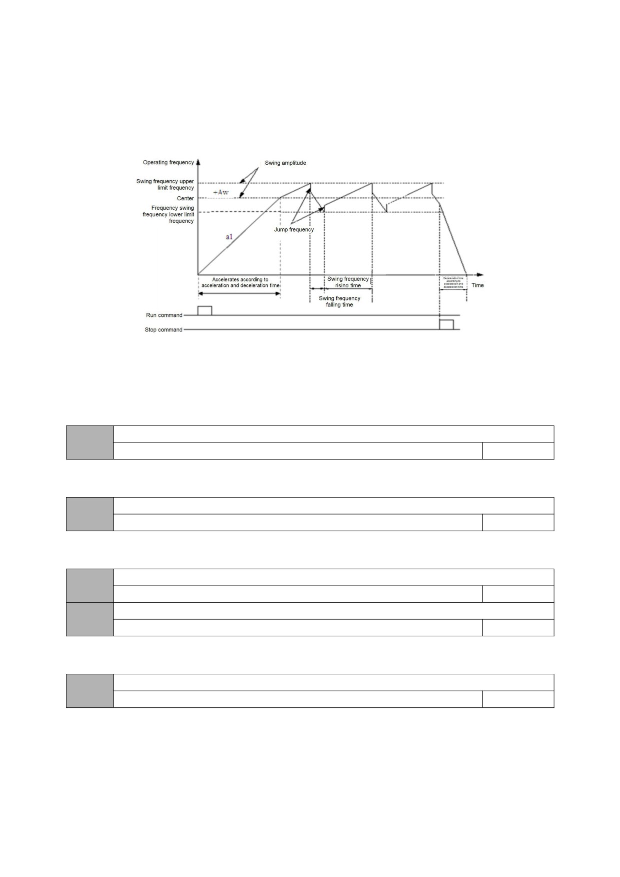
This function code defines the running time from the lower limit frequency of the swing frequency to the upper limit frequency of the swing frequency during swing
frequency operation, and the running time and delay from the upper limit frequency of the swing frequency reaching the lower limit frequency of the swing frequency
during swing frequency operation.
Swing frequency control is suitable for textile, chemical fiber and other industries and occasions that require traverse and winding functions. Its typical work is
shown in Figure 07-2. Usually the swing frequency process is as follows: first accelerate the center frequency of the swing frequency according to the acceleration time,
and then press the set swing frequency amplitude (07.11), sudden jump frequency (07.12), swing frequency rise time (07.13) and swing frequency fall time (07.14) )
Circulate running until there is a stop command to decelerate and stop according to the deceleration time.
Figure 07-2 Schematic diagram of swing frequency
Group 08-manage and display parameters
Main parameter monitoring during operation
08.00
0~30
0
For example: 08.00=2, that is, select the output voltage (D-02), then the default display item on the main monitoring interface is the current output voltage value.
Main parameter monitoring during stop
08.01
0~30
1
For example: 08.01=3, that is, bus voltage (d-03) is selected, then the default display item of the main monitoring interface is the current bus voltage value.
Auxiliary parameter display during operation (only valid for dual display keypad)
08.02
0~30
4
Auxiliary parameter display during stop (only valid for dual display keypad)
08.03
0~30
3
Same as [08.00] and [08.01] parameters!
Motor speed display coefficient
08.04
0.01~99.99
1.00
It is used to correct the display error of speed scale, and has no influence on the actual speed.
63
Initialization of the parameter
08.05
0~2
0
0: No-operation
The inverter is in normal parameter reading and writing state. Set value of function code whether it can be changed depends on the setting state of the user
password and the current working state of the inverter.
1: Restore the factory settings
All user parameters are restored to the factory settings according to the model.
2: Clear fault record
Clear the contents of fault records (d-19~d-24). After the operation is completed, this function code is cleared to 0 automatically.
FUNC key settings
08.06
0~3
0
0: JOG
1: FWD and REV switch
2: Clear ▲/▼ key frequency setting
3: REV (at this time, the RUN key defaults to FWD)
64
Appendix: Braking resistor selection:
When the drive is decelerating with a large inertia load or needs to be decelerated rapidly, the motor will be in the
state of generating electricity, and the load energy will be transferred to the DC link of the drive through the inverter
bridge, causing the bus voltage of the drive to rise. When it exceeds a certain value, the drive will report. Voltage failure,
in order to prevent the occurrence of this phenomenon, it is recommended to configure a braking resistor.
Notice:
1. Please select the resistance and power of the braking resistor according to the data provided by our company.
2. The braking resistor will increase the braking torque of the drive. The following table is the resistance power
designed according to 100% braking torque, 10% braking utilization rate, 50% braking utilization rate, and 80% braking
utilization rate. , The user can choose the brake system according to the specific working conditions.
Braking resistor
Braking resistor
Braking resistor
Braking resistance value
Minimum allowable
power (kW)
power (kW)
power (kW)
Model
(Ω)
braking resistance
(10%
braking
(50%
braking
(80%
braking
(100% braking torque)
(Ω)
capacity)
capacity)
capacity)
HV10-R40G1-1
361
0.06
0.3
0.48
100
HV10-R75G1-1
192
0.11
0.56
0.9
100
HV10-1R5G1-1
96
0.23
1.1
1.8
60
HV10-2R2G1-1
65
0.33
1.7
2.6
40
HV10-R40G1-2/G2
361
0.06
0.3
0.48
100
HV10-R75G1-2/G2
192
0.11
0.56
0.9
100
HV10-1R5G1-2/G2
96
0.23
1.1
1.8
60
HV10-2R2G1-2/G2
65
0.33
1.7
2.6
40
HV10-R75G3
653
0.11
0.6
0.9
240
HV10-1R5G3
326
0.23
1.1
1.8
170
HV10-2R2G3
222
0.33
1.7
2.6
130
HV10-004G3
122
0.6
3
4.8
80
HV10-5R5G3
89
0.75
4.1
6.6
60
65
Warranty agreement
1
The warranty period of this product is 18 months (subject to the information of fuselage bar code). During the warranty period, if the product breaks down or is
damaged under normal use according to the instruction manual, our company is responsible for free maintenance.
2
During the warranty period, if the damage is caused by the following reasons, a certain maintenance fee will be charged:
A. machine damage caused by errors in use and self-repair or modification without authorization;
B. machine damage caused by fire, flood, abnormal voltage, other natural disasters and secondary disasters;
C. hardware damage caused by man-made falling and transportation after purchase;
D. machine damage caused by not operating in accordance with the user's manual provided by our company;
E failures and damages caused by obstacles other than machines (e.g. external equipment factors);
3 In case of product failure or damage, please fill in the contents of Product Warranty Card correctly and in detail.
4. The collection of maintenance fees shall be subject to the maintenance price list newly adjusted by our company.
5 This warranty card will not be reissued under normal circumstances. Please keep this card and show it to maintenance personnel during warranty.
6. If there is any problem in the service process, please contact our agent or our company in time.
66