HC Series Card-type PLC. HNC PLC User Manual
Contents
Temperature & Humidity Module Use Manual
1. Product model list and dimension
3
2. Indicator description
3
3. Power supply specification
4
4. Environmental specifications for product
4
5. Main parameters for modules
4
5.1 Main parameters for digital temperature and humidity modules
4
5.2 Main parameters for thermal resistance and thermocouple modules
4
6. Wiring diagram
5
6.1 Digital temperature and humidity module: Single / multiple DS18B20, RW1820, DS1990 sensor input wiring diagram
5
6.2 Thermal resistance and thermocouple module wiring diagram
5
7. Terminal wiring diagram
5
8. Module parameter table (CR code is corresponding to the Modbus register address)
6
8.1 Parameter table for digital temperature and humidity modules
6
8.2 Parameter table for 4-channel thermal resistance and thermocouple modules
6
8.3 Parameter table for 8-channel thermal resistance and thermocouple modules
7
9. Expansion modules installation
8
Temperature & Humidity modules Application Case
1. Module power supply
9
2. Temperature modules need't be written any conversion program, read the current temperature value directly when access the
sensor
9
3. Programming skills for PLC
10
4. Display temperature value on HMI
10
5. Default for using engineering, when the engineering value is not used, the default code value is 0 ~ 32000
10
6. Module CR code application example: Read module channel disconnection alarm
10
2 / 11
Temperature & Humidity Module Use Manual
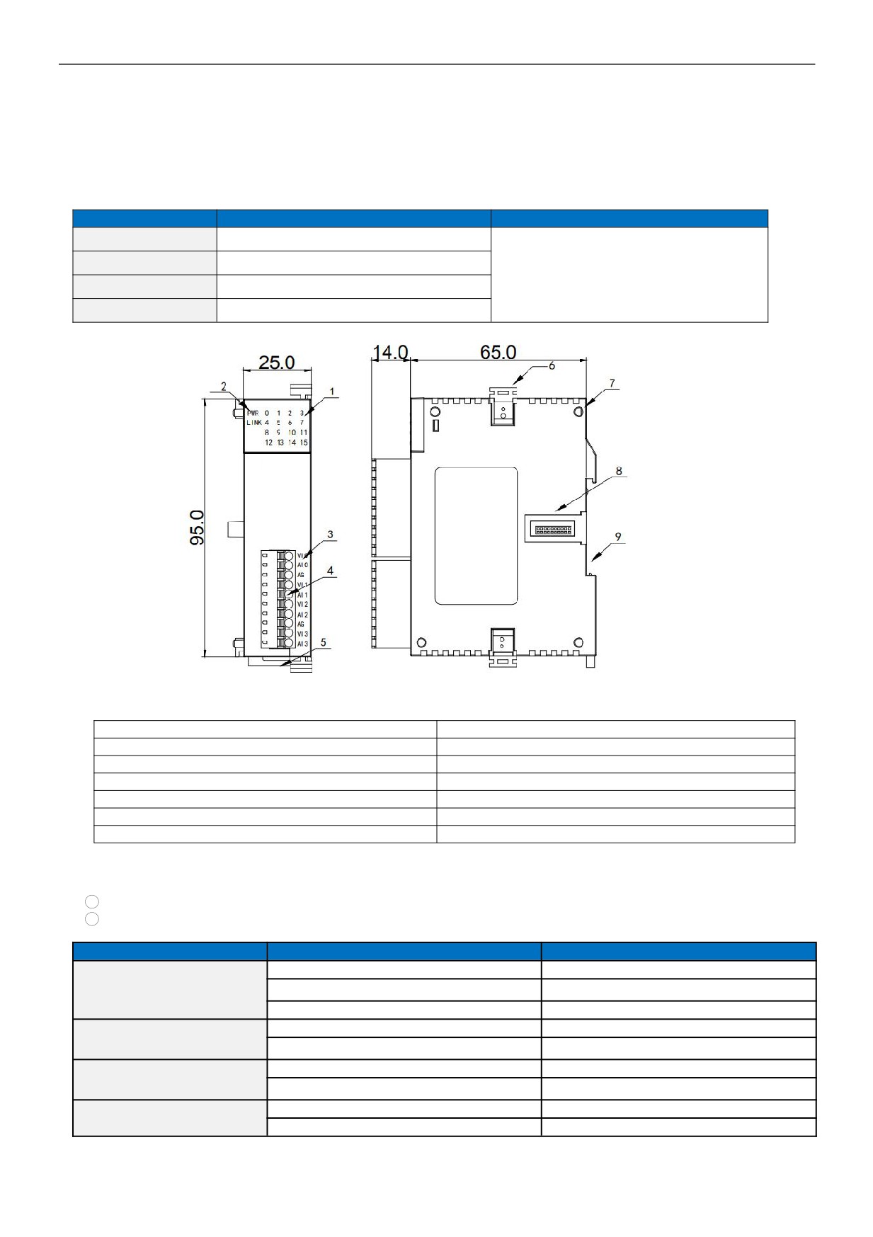
1. Product model list and dimension
Model
Power(24V)
Dimension
AE-4TC
DC24V~0.1A MAX
AE-4RC
DC24V~0.1A MAX
25*95*65 mm
AE-8TC
DC24V~0.1A MAX
AE-4DT
DC24V~0.1A MAX
1.Analog input channel indicator
8.Module expansion port
2.PWR power indicator, LINK module communication indicator
9.35mm DIN guide rail
3.Terminal definition
4.Pluggable terminal
5.Guide rail buckle
6.Module hook
7.Module connection positioning hole
2. Indicator description
1
PWR:Power indicator, green. Normally on-power normal; off - power abnormal.
2
LINK: Multi-status indicator .three colors(Red. Yellow. Green) ,as follow:
Reference processing mode
Module bus state
LINK indicator state
No communication of module
No light
MPU has identified the module but no
Normal
Constant light in green
communication
Serial or parallel port in communication
Green jitter: indicator on 30ms and off 30ms
Parallel power supply not enough,
Without serial or parallel port in communication
Yellow flicker: indicator on 0.5s and off 0.5s
must connect to external power
Yellow is darkened and jitter alternately: indicator off
With serial or parallel port in communication
supply
0.5s and jitter 0.5s
Without serial or parallel port in communication
Red flicker: indicator on 0.5s and off 0.5s
Firmware upgrade failed, reupgrade
the module firmware
Red is darkened and jitter alternately: indicator off
With serial or parallel port in communication
0.5s and jitter 0.5s
Without serial or parallel port in communication
Constant light in red
Hardware failure and maintenance
With serial or parallel port in communication
Red jitter quickly: indicator on 30ms and off 30ms
3 / 11

3. Power supply specification
Item
DC Power Supply
Power supply voltage
24VDC
-15%~+20%
Power supply frequency
——
Instantaneous surge
MAX 20A 1.5ms @24VDC
Power loss time
Within 10ms
Fuse
0.3A,250V
24V Output voltage (for input
None
and expansion)
Isolation Type
No Electrical isolation
Power Protection
DC input power polarity reverse, over voltage protection
4.
Environmental specifications for product
Item
Environment Specification
Temperature/humidity
Operating temperature:0~+55℃ Storage temperature:-25~+70℃ Humidity: 5~95%RH, No condensation
Vibration resistance
10~57 HZ, amplitude=0.075mm, 57HZ~150HZ acceleration=1G, 10 times each for X-axis, Y-axis and Z-axis
Impact resistance
15G, duration=11ms, 6 times each for X-axis, Y-axis and Z-axis
Interference immunity
DC EFT:±2500V Surge:±1000V
Over voltage resistance
1500VAC between AC terminal to ground terminal, 1 minute DC terminal to PE terminal 500VAC, 1 minute
Insulation impedance
500VDC between AC terminal and ground terminal, more than 5MΩ(All input/output points to ground 500VDC)
Operating environment
Avoid dust, moisture, corrosion, electric shock and external shocks
5.
Main parameters for modules
5.1
Main parameters for digital temperature and humidity modules
Item
AE-4DT
Input interface
DS18B20, RW1820, DS1990, SHT1x, SHT7x
Input Quantity
4 Channels 4 points
Communication interface
None
Communication speed
None
Communication protocol
None
Power supply mode
PLC MPU internal power supply
Measured distance
≤200m(Wire resistance 50Ω)
DS18B20:-55~+125℃
Measured range
SHT11:-40~+123.8℃
0~100%RH
Isolation mode
No isolation between channels,analog & digital optical isolation
5.2 Main parameters for thermal resistance and thermocouple modules
Item
RTD input
Thermocouple input
Input range
Pt100, Pt1000, Cu50, Cu100
S, K, E, J, B, N, R, Wre3/25, Wre5/26, [0,20]mV, [0,50]mV, [0,100]mV
Resolution
0.1℃
0.1℃
Input impedance
6MΩ
6MΩ
Maximum input range
±13V
±30mA
Input indication
LED light ON means normal ,OFF means external disconnection
Response time
560ms/4 Channel, 880ms/8 Channel
Digital input range
16 bits, code range:0~32000
Precision
0.1% F.S
Power supply
MPU use internal power supply, expansion modules use external power supply 24VDC ±10%
5VA
Isolation mode
Optoelectronic isolation, no isolation between channels, analog & digital optical isolation
Power consumption
24VDC ±20%,50mA(maximum)
4 / 11
6. Wiring diagram
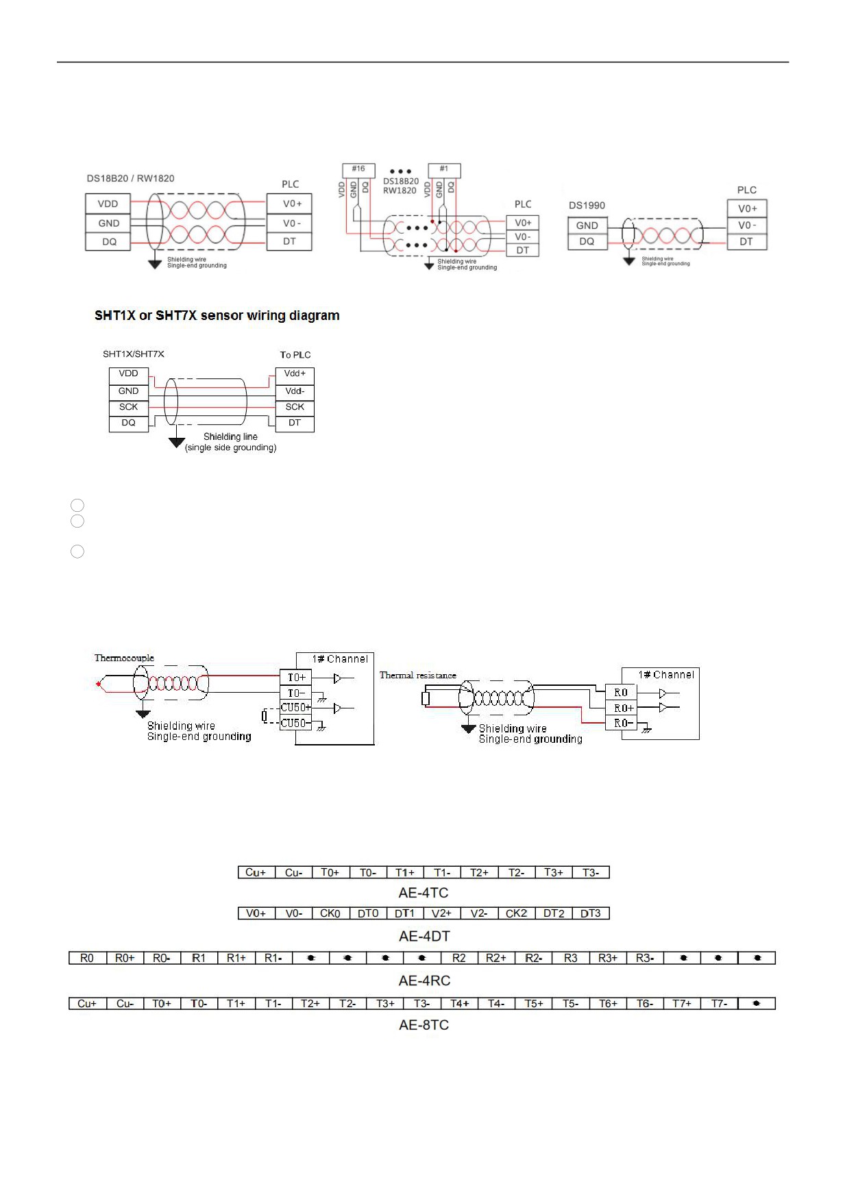
6.1 Digital temperature and humidity module: Single / multiple DS18B20, RW1820, DS1990 sensor input wiring diagram
Note:
1
VDD (Vdd +) and (V0-) are the sensor power terminals that can be wired nearby;
2
Pin connection definition of DS18B20, RW1820, DS1990, SHT1X, SHT7X sensors can be seen in respective technical
information;
3
Cables between sensor DS18B20, RW1820, DS1990 and module are recommended to use shielded 4-core twisted pair;
one set of cable can be connected to ground wire (V0-) and signal lines (DT), the other set of cable can be connected to
power supply(V0+) and ground wire (V0-), the shield is single-point grounded at the source.
6.2 Thermal resistance and thermocouple module wiring diagram
Thermocouple
1# channel
Shieding Wire(Single-end grounding)
Thermal resistance
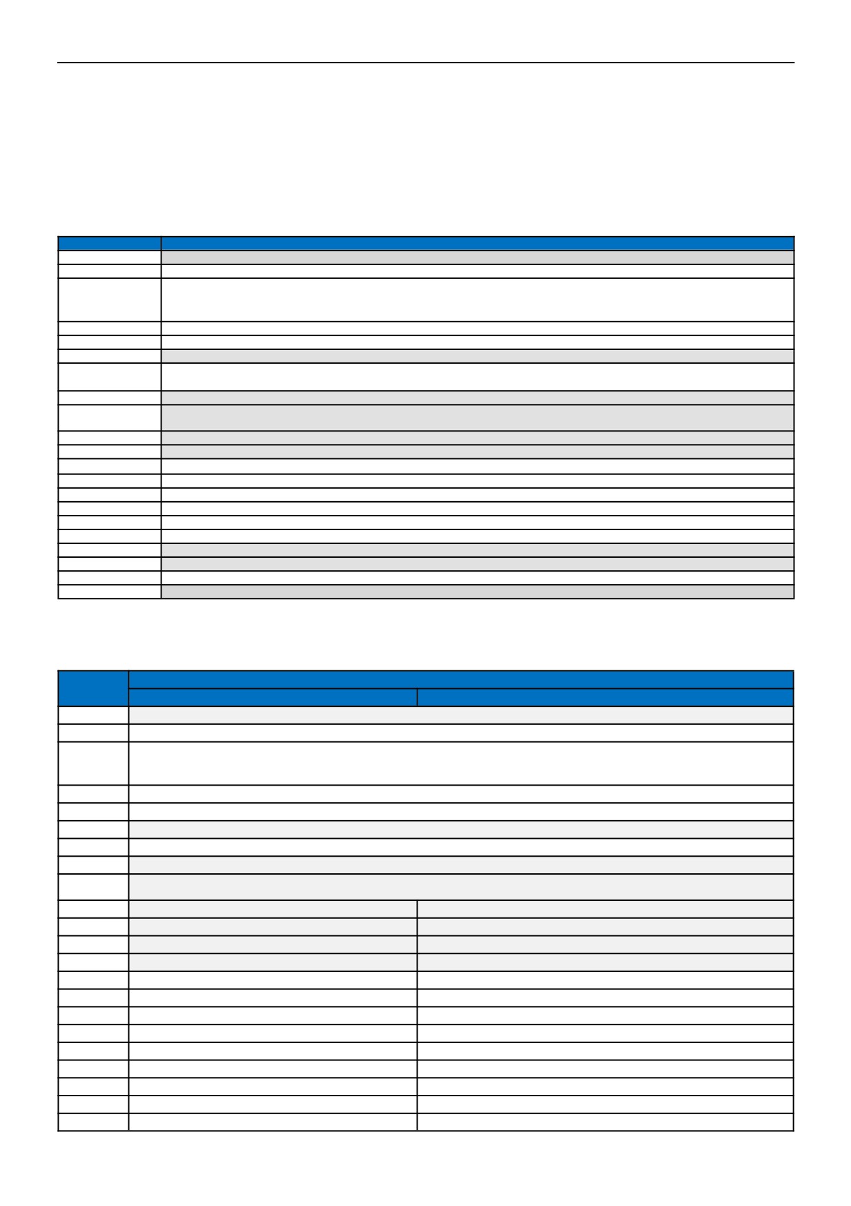
7. Terminal wiring diagram
5 / 11
8.
Module parameter table
(CR code is corresponding to the Modbus register address)
8.1 Parameter table for digital temperature and humidity modules
Note: CR code is corresponding to the Modbus register address, the gray parts are read-only ,the white parts are readable and
writable.
CR code
AE-4DT function description
00H
Low byte for module code, and high byte for module version number
01H
Communication address
Communication protocol: The low 4-bit of the low byte: 0 - N,8,2 For RTU,1 - E,8,1 For RTU,2 - O,8,1 For RTU,3 - N,7,2 For
02H
ASCII,4 - E,7,1 For ASCII,5 - O,7,1 For ASCII,6 - N,8, 1 For RTU
The high 4-bit of the low byte: 0 - 2400,1 - 4800,2 - 9600,3 - 19200,4 - 38400,5 - 57600,6 - 115200
03H~06H
Module name
07H~08H
Default IP address: 192.168.1.111
09~0AH
Reserve
High byte subnet mask(b3~b0,1 indicates 255, 0 indicates 0, for example, subnet mask 255.255.255.0, b3~b0=1110), low byte
0BH
reserved
0CH~0EH
Reserve
Error code: 0-Normal, 1-Illegal firmware identity, 2-Incomplete firmware, 3-System data access exception, 4-No external 24V
0FH
power supply
10H~13H
Temperature input value of channel 1~4
14H~17H
Humidity input value of channel 1~4
18H~1BH
Signal type of channel 1~4(0-DS18B20, RW1820, DS1990,1-SHT1x, SHT7x)
1CH
Using identification of engineering value
1DH~20H
Data lower-limit of channel 1~4
21H~24H
Data upper-limit of channel 1~4
25H~28H
A/D data bit of channel 1~4
29H~2CH
Zero point correction of channel 1~4
2DH
Sensor disconnection alarm of channel 1~4, each bit indicates 1 channel, 0- normal, 1- disconnection
2EH~2FH
Reserve
30H-3FH
Serial numbers of channel 1~4, each serial number occupies 4 registers
40H-4FH
Reserve
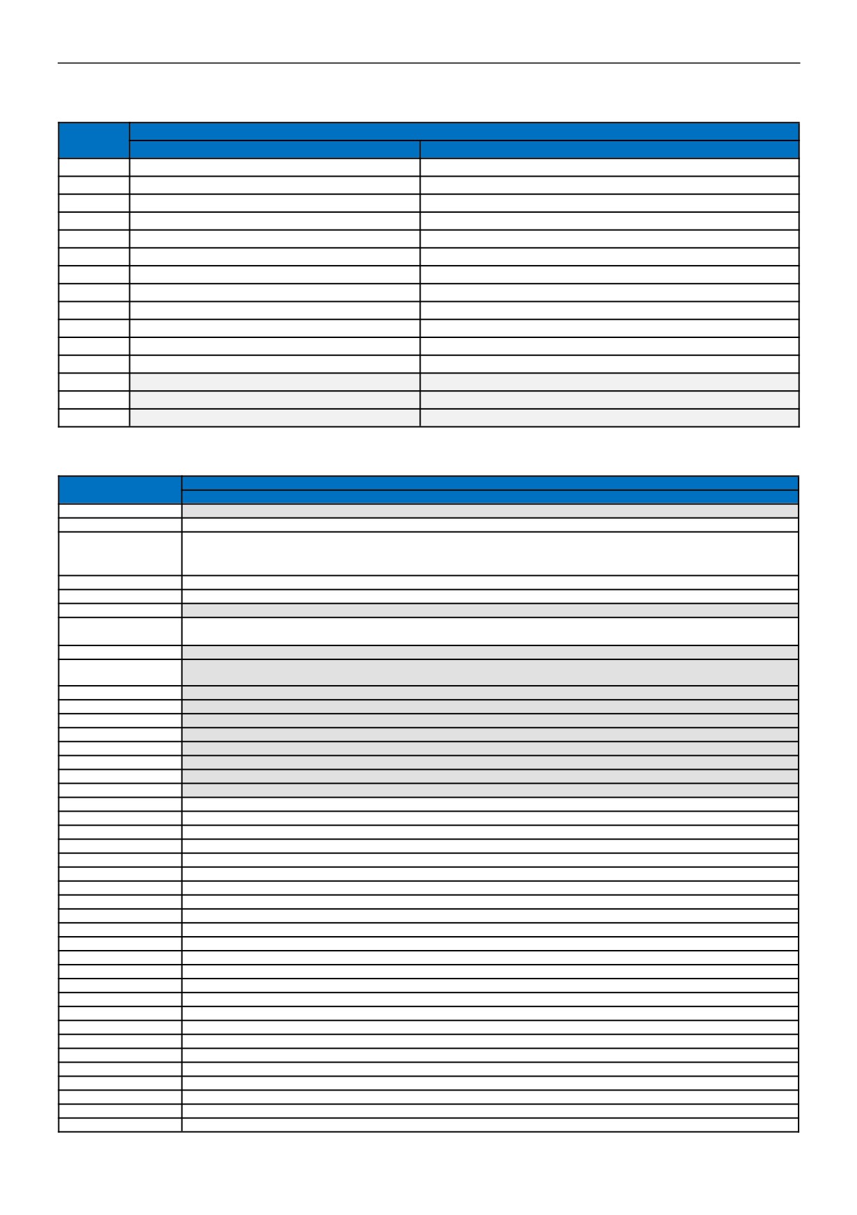
8.2 Parameter table for 4-channel thermal resistance and thermocouple modules
Note: CR code is corresponding to the Modbus register address, the gray parts are read-only ,the white parts are readable and
writable.
Function description
CR code
AE-4RC
AE-4TC
00H
Low byte for module code, and high byte for module version number
01H
Communication address
Communication protocol: The low 4-bit of the low byte: 0 - N,8,2 For RTU,1 - E,8,1 For RTU,2 - O,8,1 For RTU,3 - N,7,2 For ASCII,
02H
4 - E,7,1 For ASCII,5 - O,7,1 For ASCII,6 - N,8, 1 For RTU
The high 4-bit of the low byte: 0 - 2400,1 - 4800,2 - 9600,3 - 19200,4 - 38400,5 - 57600,6 - 115200
03H~06H
Module name
07H~08H
Default IP address: 192.168.1.111
09~0AH
Reserve
0BH
High byte subnet mask(b3~b0,1 indicates 255, 0 indicates 0, for example, subnet mask 255.255.255.0, b3~b0=1110), low byte reserved
0CH-0EH
Reserve
Error code: 0-Normal, 1-Illegal firmware identity, 2-Incomplete firmware, 3-System data access exception, 4-No external 24V power
0FH
supply
10H
channel 1 input value
channel 1 input value
11H
channel 2 input value
channel 2 input value
12H
channel 3 input value
channel 3 input value
13H
channel 4 input value
channel 4 input value
14H
channel 1 signal type, note 2
channel 1 signal type, note 3
15H
channel 2 signal type, note 2
channel 2 signal type, note 3
16H
channel 3 signal type, note 2
channel 3 signal type, note 3
17H
channel 4 signal type, note 2
channel 4 signal type, note 3
18H
Use the engineering value mark, note 5
Use the engineering value mark, note 5
19H
channel 1 engineering lower limiting value
channel 1 engineering lower limiting value
1AH
channel 2 engineering lower limiting value
channel 2 engineering lower limiting value
1BH
channel 3 engineering lower limiting value
channel 3 engineering lower limiting value
1CH
channel 4 engineering lower limiting value
channel 4 engineering lower limiting value
6 / 11
Function description
CR code
AE-4RC
AE-4TC
1DH
channel 1 engineering upper limiting value
channel 1 engineering upper limiting value
1EH
channel 2 engineering upper limiting value
channel 2 engineering upper limiting value
1FH
channel 3 engineering upper limiting value
channel 3 engineering upper limiting value
20H
channel 4 engineering upper limiting value
channel 4 engineering upper limiting value
21H
channel 1 sampling frequency, note 1
channel 1 sampling frequency, note 1
22H
channel 2 sampling frequency, note 1
channel 2 sampling frequency, note 1
23H
channel 3 sampling frequency, note 1
channel 3 sampling frequency, note 1
24H
channel 4 sampling frequency, note 1
channel 4 sampling frequency, note 1
25H
channel 1 zero point correction value
channel 1 zero point correction value
26H
channel 2 zero point correction value
channel 2 zero point correction value
27H
channel 3 zero point correction value
channel 3 zero point correction value
28H
channel 4 zero point correction value
channel 4 zero point correction value
29H
Channel 1~4 input disconnection alarm, note 4
Channel 1~4 input disconnection alarm, note 4
2AH
Reserve
Reserve
2BH~2FH
8.3 Parameter table for 8-channel thermal resistance and thermocouple modules
Function description
CR code
AE-8TC
00H
Low byte for module code, and high byte for module version number
01H
Communication address
Communication protocol: The low 4-bit of the low byte: 0 - N,8,2 For RTU,1 - E,8,1 For RTU,2 - O,8,1 For RTU,3 - N,7,2 For
02H
ASCII,4 - E,7,1 For ASCII,5 - O,7,1 For ASCII,6 - N,8, 1 For RTU
The high 4-bit of the low byte::0 - 2400,1 - 4800,2 - 9600,3 - 19200,4 - 38400,5 - 57600,6 - 115200
03H~06H
Module name
07H~08H
Default IP address:192.168.1.111
09~0AH
Reserve
High byte subnet mas(b3~b0,1indicates 255, 0 indicates 0, for example subnet mask 255.255.255.0, b3~b0=1110),low byte
0BH
reserved
0CH~0EH
Reserve
Error code: 0-Normal, 1-Illegal firmware identity, 2-Incomplete firmware,
3-System data access exception, 4-No external 24V
0FH
power supply
10H
channel 1 input value
11H
channel 2 input value
12H
channel 3 input value
13H
channel 4 input value
14H
channel 5 input value
15H
channel 6 input value
16H
channel 7 input value
17H
channel 8 input value
18H
channel 1 signal type, note 2
19H
channel 2 signal type, note 2
1AH
channel 3 signal type, note 2
1BH
channel 4 signal type, note 2
1CH
channel 5 signal type, note 2
1DH
channel 6 signal type, note 2
1EH
channel 7 signal type, note 2
1FH
channel 8 signal type, note 2
20H
Use the engineering value mark, note 5
21H
channel 1 engineering lower limiting value
22H
channel 2 engineering lower limiting value
23H
channel 3 engineering lower limiting value
24H
channel 4 engineering lower limiting value
25H
channel 5 engineering lower limiting value
26H
channel 6 engineering lower limiting value
27H
channel 7 engineering lower limiting value
28H
channel 8 engineering lower limiting value
29H
channel 1 engineering upper limiting value
2AH
channel 2 engineering upper limiting value
2BH
channel 3 engineering upper limiting value
2CH
channel 4 engineering upper limiting value
2DH
channel 5 engineering upper limiting value
2EH
channel 6 engineering upper limiting value
2FH
channel 7 engineering upper limiting value
7 / 11
Function description
CR code
AE-8TC
30H
channel 8 engineering upper limiting value
31H
channel 1 sampling frequency, note 1
32H
channel 2 sampling frequency, note 1
33H
channel 3 sampling frequency, note 1
34H
channel 4 sampling frequency, note 1
35H
channel 5 sampling frequency, note 1
36H
channel 6 sampling frequency, note 1
37H
channel 7 sampling frequency, note 1
38H
channel 8 sampling frequency, note 1
39H
channel 1 zero point correction value
3AH
channel 2 zero point correction value
3BH
channel 3 zero point correction value
3CH
channel 4 zero point correction value
3DH
channel 5 zero point correction value
3EH
channel 6 zero point correction value
3FH
channel 7 zero point correction value
40H
channel 8 zero point correction value
41H
Channel 1~8 input disconnection alarm, note 4
42H~4FH
Reserve
Note:
1
Sampling frequency: 0 - 2 times, 1 - 4 times, 2 - 8 times, 3 - 16 times, 4 - 32 times, 5 - 64 times, 6 -
128 times, 7 -
256
times
2
RTD signal type: 0 - Pt100, 1 - Pt1000, 2 - Cu50, 3 - Cu100
3
Thermocouple signal type: 0 - S, 1 - K, 2 - T, 3 - E, 4 - J, 5 - B, 6 - N, 7 - R, 8 - Wre3/25, 9- Wre5/26,
10 - [0,20]mV,
11 -
[0,50]mV, 12 - [0,100]mV
4
Disconnection alarm:Each bit indicates 1 channel, 0-normal, 1-disconnection
5
5. Use the engineering value mark:Each bit indicates 1 channel, 0-No, 1-Yes
9.
Expansion modules installation
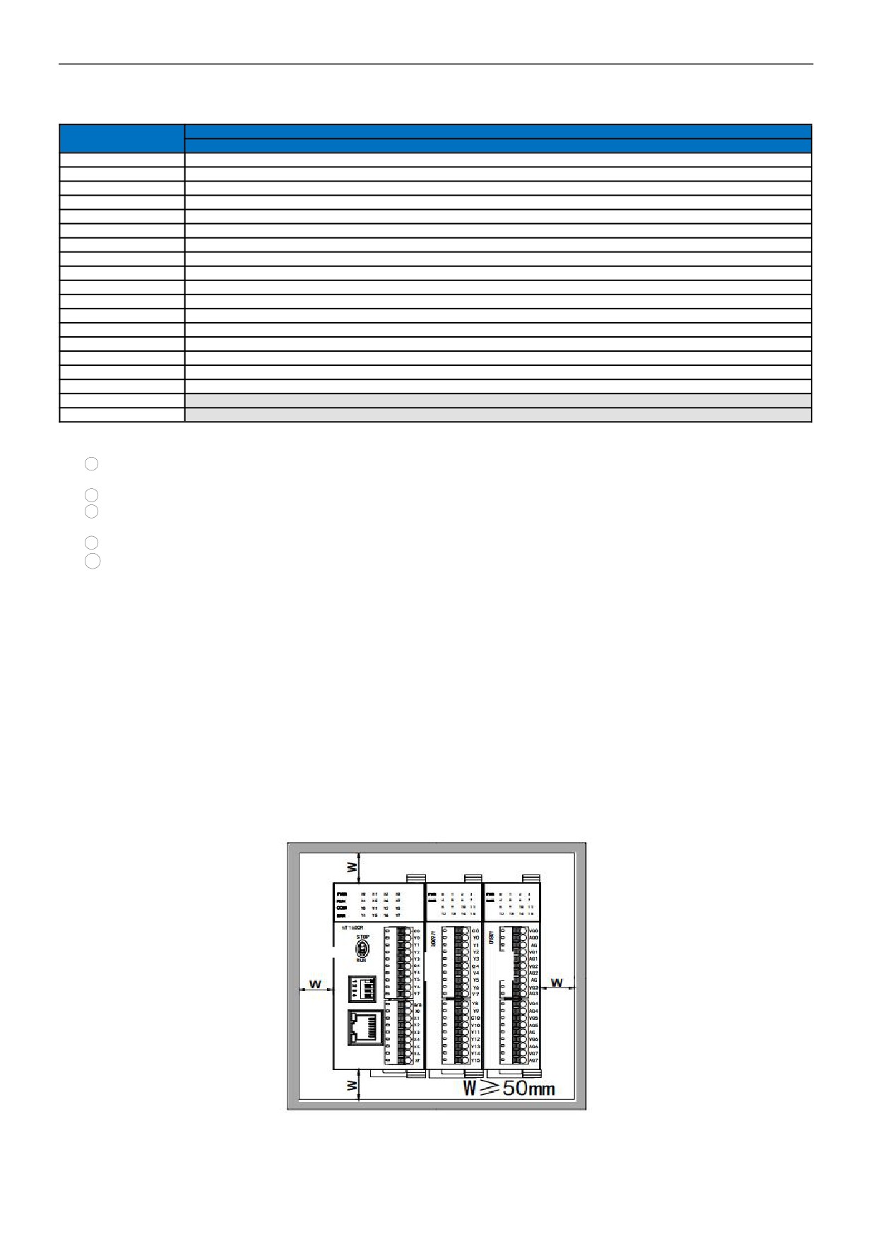
The PLC should be secured to an enclosed cabinet while mounting.,For heat dissipation, make sure to provide enough space
between the unit and all sides of the cabinet. (See the figure.)
Rail Mounting: Use standard 35 mm rail.
Expansion module connection method
The parallel interface on the lower right side of the last module (MPU or expansion module) is inserted into the parallel interface on the lower
left side of the next module and hooked with small cards on both sides. The parallel interface on the right side of this module is used as the
next expansion module. Connect all expansion modules in this way in sequence.
8 / 11
Temperature & Humidity modules Application Case
1. Module power supply
It can be used as the extension module of HCS/G/M series PLC MPU; when the module is hung behind the MPU through the
expansion port,, the external power supply is not required, and the module is powered by the parallel port of the MPU. If the power
supply of the module is insufficient (the PWR power indicator on the module is not on).
2. Temperature modules needn't be written any conversion program, read the current temperature value directly when access the
sensor
For example, the MPU HCG-8X8Y-TN respectively is expanded with three modules of AE-4TC、AE-4RC and AE-8TC through the
parallel port from left to right, assuming the scene:
Thermocouple module AE-4TC input channel 1, signal type is K, input channel 2, signal type is E;
Thermal resistance module AE-4RC input channel 1, signal type is PT100, AE-4RC input channel 2, signal type is PT1000;
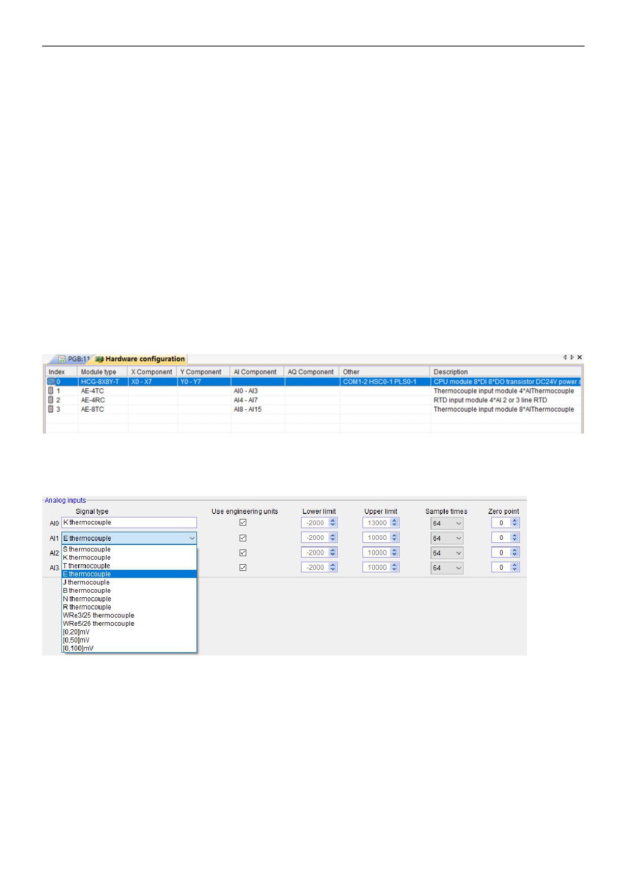
First enter the PLC programming software menu bar - view - hardware configuration, in accordance with the external order of
actual modules to add the module models, after added, the analog addresses will be automatically arranged, as shown below:
HNC temperature and humidity module need't be written any conversion program, for the above measuring temperature, we only
need to select the corresponding channel signal type, check the use of engineering value and full index number by default, for
example, the above module AE-4TC input channel 1, the signal type is K; the input channel 2, the signal type is E, as long as we
set the hardware configuration:
In this way, after configuration, as long as connect the K-type thermocouple to channel 1, then directly read AI0 register value, AI0
= 123, that is the actual value of 12.3 ℃. In the same way, connect E-type thermocouple to channel 2, read AI2 value, such as AI2
= 3456, that is the actual value of 345.6 ℃.
As we know that HNC temperature and humidity modules can be set the signal type of each channel arbitrarily, so for the AE-4RC
module, after configuration, we can read the temperature value directly when connecting the corresponding sensor to the
channel.
9 / 11
3. Programming skills for PLC
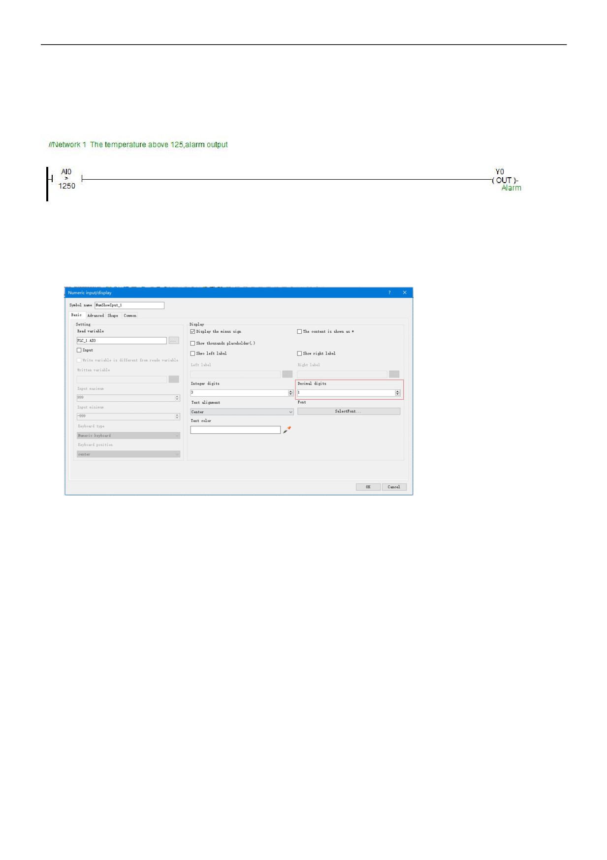
If you want to write the alarm program that temperature exceeds the setting value, for example, when the temperature is more
than 125℃, it will alarm, the program of PLC can be written as follows:
4. Display temperature value on HMI
If the configuration, touch screen, text and other PC softwares want to display the current temperature, only need to set 1
decimal place on the numerical display primitive, then the read value will be automatically reduced 10 times in the configuration,
that is the actual temperature value, for example, you can set 1 on decimal places of HTCloud Designer settings:
So that when the PLC read AI0 value, AI0=123, that is the actual value of 12.3℃, there is no need to have data processing in PLC
and configuration, only set the 1 decimal places on the numerical display primitive, then it will be automatically reduced by 10
times, displaying value of 12.3, that is the actual value of 12.3℃.
5. Default for using engineering, when the engineering value is not used, the default code value is 0 ~ 32000
When using the engineering value, the linear transformation is specified by the lower limit and the upper limit value, and the
program is automatically transformed. When the engineering value is not used, all types are unified to correspond with 0 ~ 32000
code value.The same case of temperature measurement, this time can according to the linear transformation formula:
Out = (In - InDw) * (OutUp- OutDw) / (InUp- InDw) + OutDw to write the conversion program, or use the SC linear transformation
instructions to calculate directly.
HNC analog used easily, it is recommended to check the use of engineering value, so that the analog will be very convenient
without writing any program.
6. Module CR code application example: Read module channel disconnection alarm
In this example, in order to read the external sensor disconnection information of AE-4TC module, the disconnection alarm data of
AE-4TC module input channel 1-4 is stored in CR29, that is, 29H (hexadecimal), decimal 41. (More CR contents can be found in
the software online help - hardware manual - expansion module parameters within the corresponding model). This program is as
follows:
10 / 11
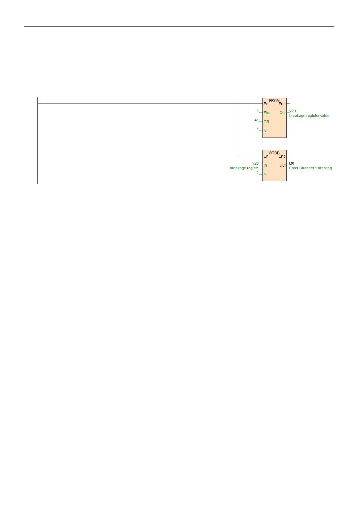
Slot: Position number, AE-4TC is the first module, so fill in 1;
CR: Module disconnection alarm CR41, that is, 29H (hexadecimal) = 41 (decimal), it can be directly input 41 or 0x29 into the
instruction CR terminal;
N: Number for readings, 1 register for 16 bits, low 4 bits is corresponding channel 1-4, disconnection for 1 (ON), normal for 0
(OFF).