HNC PLC User Manual. Classic Programmable Logic Controller
Contents
Digital Module User Manual
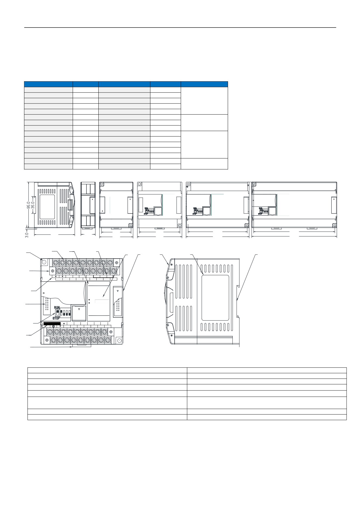
1. Product Model List and Dimension
3
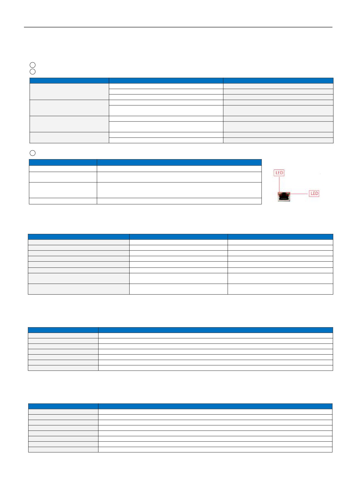
2. Indicator Description
4
3. Power Supply Specification
4
4. Environmental Specifications for Product
4
5. Digital Input (DI) Specification
4
6. Digital Output (DO) Specification
5
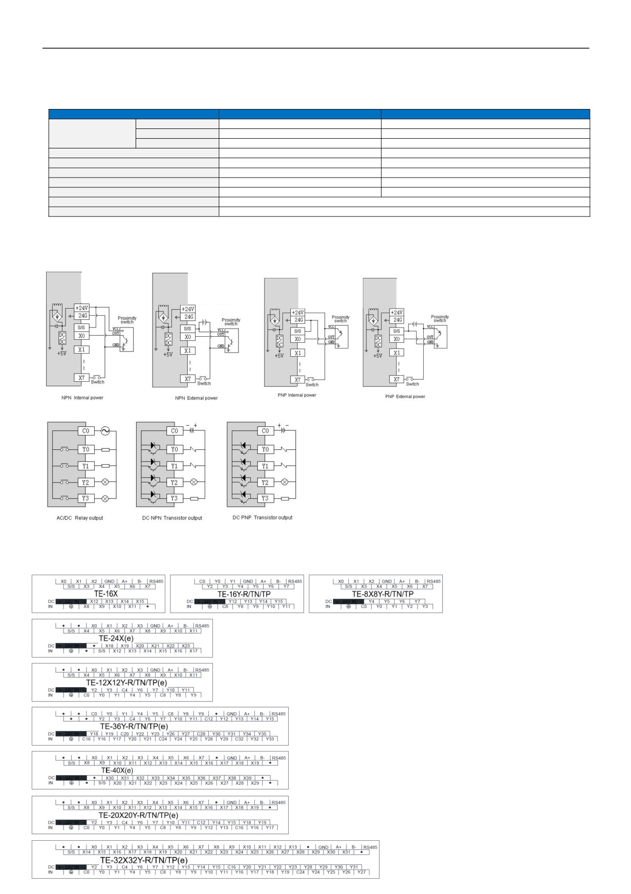
7. Digital Input/Output (DI/DO) Wiring Diagram
5
8. Terminal Wiring Diagram
5
9. Module Parameter Table (CR code is corresponding to the Modbus register address)
6
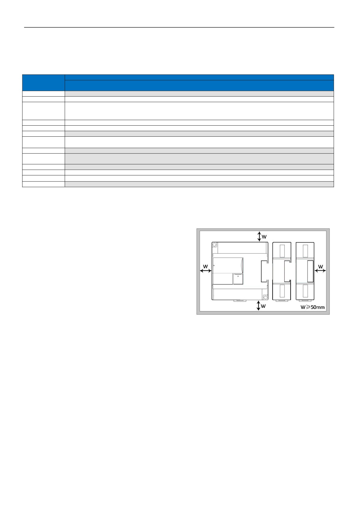
10. Mounting and Installation
6
Digital Module Application Case
1. Module Used as Remote IO
7
1.1. Module power supply
7
1.2. Communication port introduction
7
1.3. Communication protocols and default parameters
7
1.4. Module parameter configuration method introduction, when the module is used as remote IO
8
1.5. Parameter configuration example: The module is configured by programming software remote module tool
8
Hardware connection
8
Software operation steps
8
1.6. Remote IO application example(RS485): The PLC reads the 12 input channels status of the TE-12X12Y-TN module..10
1.7. Remote IO application example (RS485): The PLC writes the 12-channel output values of TE-12X12Y-TN module
10
1.8. Remote IO application example(Ethernet): PLC read&write each channel DI/DO values of TE-32X32Y-TNe
11
2 / 11
Digital Module User Manual
1.
Product Model List and Dimension
Ethernet Model
24VDC
Model
24VDC
Dimension
TE-16X
0.03A
TE-16Y-R
0.15A
TE-16Y-TN/R
0.1A
70×95×82mm
TE-8X8Y-R
0.08A
TE-8X8Y-TN/P
0.06A
TE-24Xe
0.06A
TE-24X
0.03A
TE-12X12Y-Re
0.16A
TE-12X12Y-R
0.13A
93×95×82mm
TE-12X12Y-TN/Pe
0.12A
TE-12X12Y-TN/P
0.09A
TE-40Xe
0.07A
TE-40X
0.04A
TE-36Y-Re
0.34A
TE-36Y-R
0.31A
TE-36Y-TN/Pe
0.23A
TE-36Y-TN/P
0.2A
131×95×82mm
TE-20X20Y-Re
0.18A
TE-20X20Y-R
0.15A
TE-20X20Y-TN/Pe
0.16A
TE-20X20Y-TN/P
0.13A
TE-32X32Y-Re
0.33A
TE-32X32Y-R
0.3A
177×95×82mm
TE-32X32Y-TN/Pe
0.23A
TE-32X32Y-TN/P
0.23A
ON
DIP
ON DIP
ON DIP
1
2
3
4
1
2
3
4
1
2
3
4
61.5
84.5
123.0
168.7
84.0
30.0
70.0
93.0
131.0
177.0
8
9
10
1
13
14
11
12
15
2
X0
X1
X2
X3
GND A+
B- RS485
S/S
X4
X5
X6
X7
X8
X9
X10
X11
0
1
2
3
4
5
6
7
8
9 10 11
DI(X)
3
POW
4
LINK
ON DIP
DI(X)
1
2
3
4
12131415 16 17 18 19
20 2122 23
5
DCIN
X18
X19
X20
X21 X22
X23
S/S
X12
X13
X14 X15
X16
X17
6
7
1.
Fixed hole
8.
Removable terminal
2.
Removable terminal screw
9.
Digital channel indicator
3.
Terminal definition
10.
RS485 communication port
4.
Module expansion port
11.
PWR power indicator、LINK module communication indicator
5.
DIP switch(8/16-channel module without DIP switch)
12.
Module expansion port
6.
External power supply terminal ( DC24V and AC220V , Generally
13.
Transparent cover of module terminal
powered by the host PLC)
7.
Guide rail buckle
14.
Module nameplate
15.
35mm DIN guide rail
3 / 11
2.
Indicator Description
1
PWR: power indicator .green,constant light -Power normal; Not light - Power abnormal.
2
LINK: multi-status indicator, three colors (Red/ Yellow/ Green), as follow:
Reference processing mode
Module bus state
LINK indicator state
No communication of module
No light
Normal
MPU has identified the module but no communication
Constant light in green
Serial or parallel port in communication
Green jitter: indicator on 30ms and off 30ms
Parallel power supply not enough,
Without serial or parallel port in communication
Yellow flicker: indicator on 0.5s and off 0.5s
must connect to external power
Yellow is darkened and jitter alternately: indicator off
With serial or parallel port in communication
supply
0.5s and jitter 0.5s
Without serial or parallel port in communication
Red flicker: indicator on 0.5s and off 0.5s
Firmware upgrade failed, reupgrade
Red is darkened and jitter alternately: indicator off
the module firmware
With serial or parallel port in communication
0.5s and jitter 0.5s
Without serial or parallel port in communication
Constant light in red
Hardware failure and maintenance
With serial or parallel port in communication
Red jitter quickly: indicator on 30ms and off 30ms
3
RJ45 Ethernet indicator: there are two Ethernet LEDs, green and yellow, as shown on the picture:
Color
Status description
Green light is long bright
Physical connection of TCP module and external device is normal;
TCP module fails to connect with external device or the module itself is
Green light goes out
abnormal
TCP module is connected to an external device normally, and blinking
Yellow light blinks
frequency indicates the data transmission speed. When speed is fast, human
eye is not easy to distinguish, at this time, yellow light is long bright.
Yellow light goes out
No data transmission communication of TCP module and external device
3.
Power Supply Specification
Item
DC Power Supply
AC Power Supply
Power supply voltage
24VDC
-15%~+20%
100~240VAC
Power supply frequency
——
50~60Hz
Instantaneous surge
MAX 20A 1.5ms @24VDC
20A 1.5ms MAX @220VAC
Power loss time
10ms or less
20ms or less @220VAC
Fuse
0.3A,250V
2A, 250V
24V Output voltage (for input and expansion)
None
24V, -15%~+15%, 200mA (Max)
Transformer isolation or optoelectronic
Isolation type
No Electrical isolation
isolation,1500VAC/1 minute
DC input power polarity reverse, over voltage
Power protection
DC 24V output over current protection
protection
4.
Environmental Specifications for Product
Item
Environment Specification
Temperature/Humidity
Operating temperature:0~+55℃ Storage temperature:-25~+70℃ Humidity: 5~95%RH, No condensation
Vibration resistance
10~57 HZ, amplitude=0.075mm, 57HZ~150HZ acceleration=1G, 10 times each for X-axis, Y-axis and Z-axis
Impact resistance
15G, duration=11ms, 6 times each for X-axis, Y-axis and Z-axis
Interference immunity
DC EFT:±2500V Surge:±1000V
Over voltage resistance
1500VAC/1min between AC terminal and PE terminal, 500VAC/1min between DC terminal and PE terminal
Insulation impedance
Between AC terminal and PE terminal @500VDC,>=5MΩ ,all input/output points to PE terminal @500VDC
Operating environment
Avoid dust, moisture, corrosion, electric shock and external shocks
5.
Digital Input (DI) Specification
Item
Digital Input (DI)
Input signal
No voltage contact or NPN/PNP
Action driving
ON>3.5mA OFF<1.5mA
Input impedance
Input Impedance≈4.3KΩ
Maximum input current
10mA
Reaction time
6.4ms DEFAULT, can be configured to 0.8~51.2ms
Isolation type
Independent optoelectronic isolation for each channel
Input indication
LED's lighting indicates ON, no light indicates OFF
Power supply
MPU internal power supply:DC power supply (SINK or SOURCE) 5.3mA@24VDC
4 / 11
6.
Digital Output (DO) Specification
Item
Output point type : Relay - R
NPN or PNP transistor output T/P
Resistive Load
2A/1 point, 8A/4 points COM
0.5A/1 point, 2A/4 points COM
Inductive Load
50VA
5W/DC24V
Maximum load
Lamp load
100W
12W/DC24V
Minimum Load
10mA
2mA
Voltage Specification
Below 250VAC, 30VDC
30VDC
Drive Capability
Maximum contact capacity: 5A/250VAC
1A MAX, 10 seconds
Reaction Time
Off→On 10ms, On→off 5ms
Off→On 10μs, On→Off 120μs
Isolation Type
Mechanical isolation
Independent optoelectronic isolation for each channel
Output Indication
LED's lighting indicates ON, no light indicates OFF
Power Supply
MPU internal 24VDC power supply
7.
Digital Input/Output (DI/DO) Wiring Diagram
8.
Terminal Wiring Diagram
9.
Module Parameter Table (CR code is corresponding to the Modbus register address)
Note: CR code is corresponding to the Modbus register address, the gray parts are read-only ,the white parts are readable and
writable.
Function Description
CR Code
TE-16X, TE-16Y-R, TE-16Y-TN/TP, TE-8X8Y-R, TE-8X8Y-TN/TP, TE-24X(e), TE-12X12Y-R(e),, TE-12X12Y-TN/TP(e),
TE-40X(e), TE-36Y-R(e), TE-36Y-TN/TP(e), TE-20X20Y-R(e), TE-20X20Y-TN/TP(e), TE-32X32Y-R(e), TE-32X32Y-TN/TP(e)
00H
Low byte for module code, and high byte for module version number.
01H
Communication address
Communication protocol: The low 4-bit of the low byte: 0 - N,8,2 For RTU,1 - E,8,1 For RTU,2 - O,8,1 For RTU,3 - N,7,2 For
02H
ASCII,4 - E,7,1 For ASCII,5 - O,7,1 For ASCII,6 - N,8, 1 For RTU
The high 4-bit of the low byte: 0 - 2400,1 - 4800,2 - 9600,3 - 19200,4 - 38400,5 - 57600,6 - 115200
03H~06H
Module name
07H~08H
Default IP address: 192.168.1.111
09~0AH
Reserve
High byte subnet mask (b3~b0,1indicates 255, 0 indicates 0, for example, subnet mask255.255.255.0 ,b3~b0=1110), low byte
0BH
Reserved
0CH~0EH
Reserve
Error code: 0-Normal, 1-Illegal firmware identity, 2-Incomplete firmware, 3-System data access exception, 4-No external 24V power
0FH
supply
10H~4FH
DI channel 1~64 input value
50H~8FH
DO channel 1~64 output value
90H
DI filter time ms,0 - 0.8、1 - 1.6、2 - 3.2、3 - 6.4、4 - 12.8、5 - 25.6、6 - 51.2
91H~9FH
Reserve
10. Mounting and Installation
The modules should be secured to an enclosed cabinet while
mounting. For heat dissipation, make sure to provide a minimum
clearance of 50mm between the unit and all sides of the cabinet.
Rail Mounting: Use standard 35 mm rail.
Screw Mounting: Each remote module has two positioning screw
holes, the diameter of the hole is 4.5mm. Please refer to the
dimension figure for the location of the positioning holes and their
spacing.
To avoid over temperature and for a better heat dissipation, do not
mount it to a position near to the bottom/top of the cabinet. Do not mount it in vertical direction.
6 / 11
Digital Module Application Case
1. Module Used as Remote I/O
The remote module is built-in one RS485 communication port (Some models with Ethernet communication port) supports serial
bus(Use the RS485 communication port of module networking with communication port of host PLC, and host PLC controls the
remote module by communication instructions), when using the serial bus to expand (that is, remote IO module), it doesn't have
expansion limit of system points and can be distributed installation.
Distributed installation is very important for the system which needs to collect and monitor a large number of decentralized digital
or analog signals(temperature, humidity, differential pressure, blowing rate, flow, fan speed, valve opening, etc.), it can easily
achieve distributed installation control and unlimited points of expansion, greatly improving the control system configuration
flexibility and future control expansion capabilities, reducing the number of signal wiring, also reducing the interference problem of
too long analog signal line, saving the project investment costs.
The following will introduce the operation key points and techniques.
1.1 Module power supply
The power supply is 24VDC. If the module is powered normally, the PWR indicator will light.
1.2 Communication port introduction
1
All digital modules are built-in RS485 port.
2
RS485 communication port and Ethernet port can be used at the same time, for example, the RS485 of module
communicates with PLC, Ethernet port can also communicates with multiple host computers (up to 7).
1.3 Communication protocols and default parameters
RS485: Support standard Modbus RTU / ASCII protocol, it can communicate with the configuration, touch screen, text display,
PLC and other third-party host computer, which must support Modbus protocol. Among them:
z
Address: 1 ~ 254 can be set; module address is divided into soft address and hard address, hard address has the highest
priority.
z
Soft address: The address set through programming software - remote tool, address range 1-254;
z
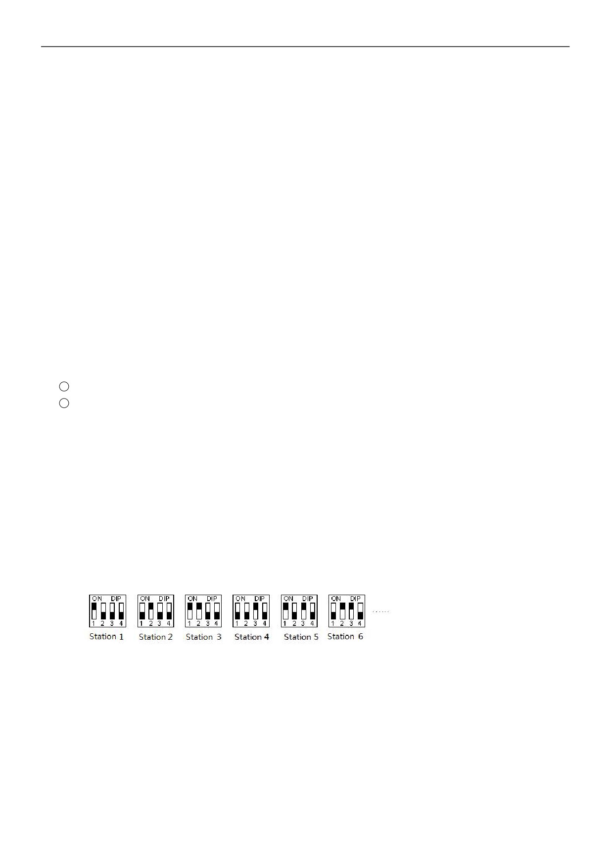
Hard address: The address set through the 4-bit DIP switch of module hardware, address range 1-15. Hardware address
setting example:
Baud rate: 2400、4800、9600、19200、38400、57600、115200 optional;
Data format : N, 8, 2 RTU, E, 8, 1 RTU, O, 8, 1 RTU, N, 8, 1 RTU, E, 7, 1 ASCII, O, 7, 1 ASCII, N,7,2 ASCII optional.
RS485 default parameter:19200,N 8 2 RTU,station number is 1.
Ethernet +: Support the standard Modbus TCP protocol, it can communicate with the configuration, touch screen, PLC and other
third-party host computers, which must support Modbus TCP protocol. Among them:
Ethernet default parameters:
IP: 192.168.1.111
Subnet mask: 255.255.255.0
Gateway: 192.168.1.1
7 / 11
1.4 Module parameter configuration method introduction, when the module is used as remote IO
There are two ways to configure remote IO parameters:
1
It can be configured via programming software - tools - remote modules (recommended);
2
It can be configured via MODW instructions through the serial communication.
1.5 Parameter configuration example: The module is configured by programming software remote module tool
Hardware connection
1
Through the RS485 communication port (the terminals of A +,B- on the module) connection: If the computer has a serial port,
you can use the converter of 232 to 485 connecting with the module; if it has one USB interface, you can use the converter of
USB to 485 connecting with the module.
2
Through the connection of Ethernet + communication interface: You can connect the module with the computer's network port
directly by the standard network cable, or take the computer and module connected to the switch.
Software operation steps
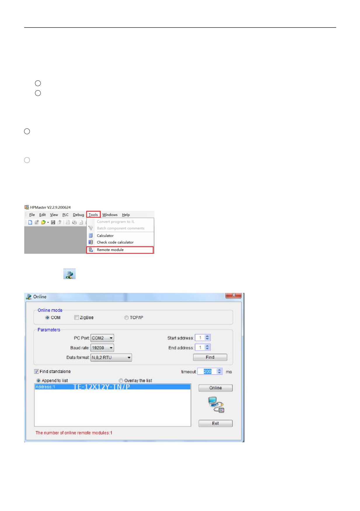
Click on the the menu bar tool of programming software- "remote module":
Click the button
in the pop-up window to open the "Online" window. The module default address is 1,19200, N 8 2 RTU, the
online success is as follows:
If there is only one machine connected with RS485 line, then check "stand-alone search"; if there are more than one, then remove
the button of "stand-alone search", and set the start address and end address, so that all the machines connected with 485 line
can be found and achieve parameter configuration.
8 / 11
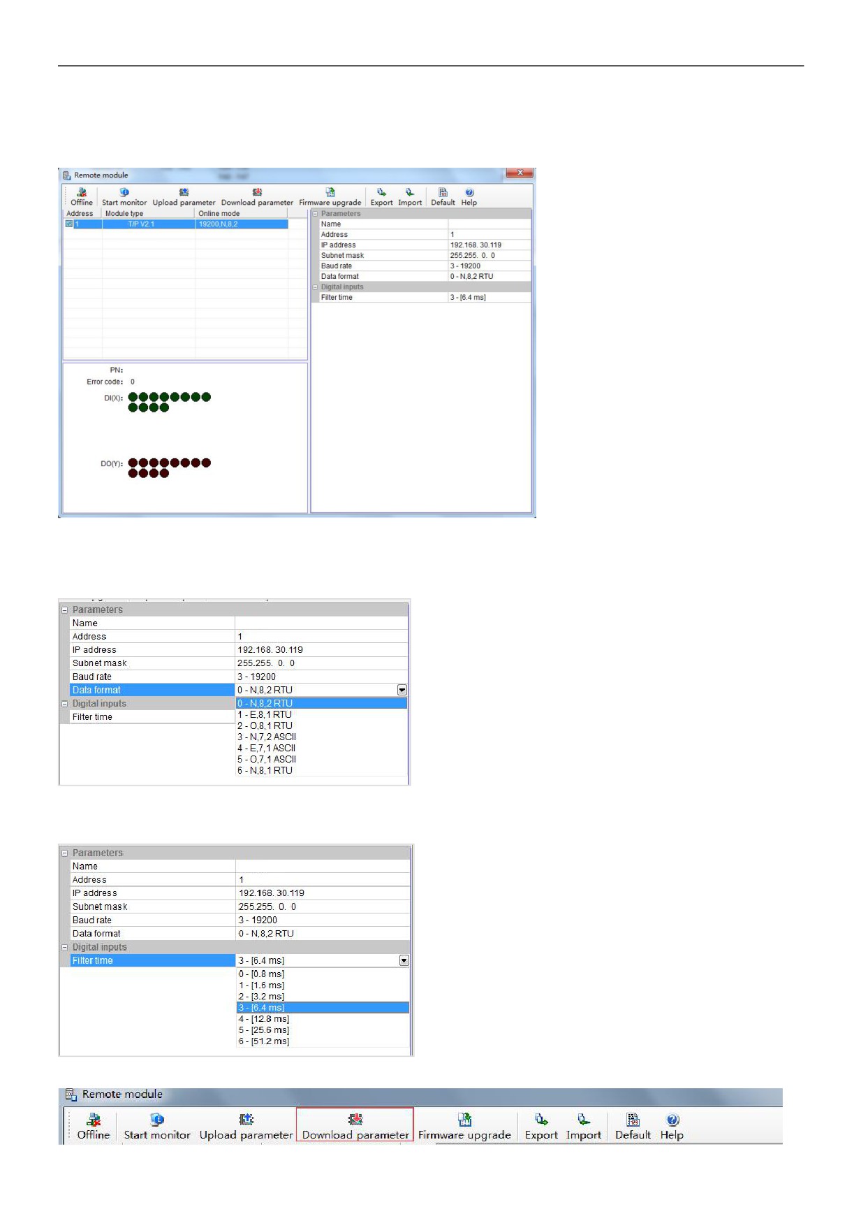
Click to exit, enter the configuration interface, as shown below:
We can change the module name, address, IP, subnet mask, baud rate, data format and other communication parameters in the
communication parameter area.
In the external switch input area, we can set the channel filter time.
After setting, select the "Download parameter" to download the parameter into the module.
9 / 11
In addition, we can do the following operations through the remote module tool:
1
Online monitoring the channel value of module, error code.
2
Upload the module parameter, upgrade the module firmware, then make the module support new features.
3
It can export the module configuration to save or import and restore the default value.
1.6 Remote IO application example(RS485): The PLC reads the 12 input channels status of the TE-12X12Y-TN module
1
Hardware wiring: PLC connects to 485 port of module by shielded twisted pair, A + connects to A +, B- connects to B-, if the
PLC connects to multiple remote IO modules, it needs to use hand in hand way to connect.
2
Modbus address: It can be seen from the above CR parameter list of digital module that the CR code 10H ~ 1CH of
TE-12X12Y-TN module stores the input status of channels 1 ~ 12.
3
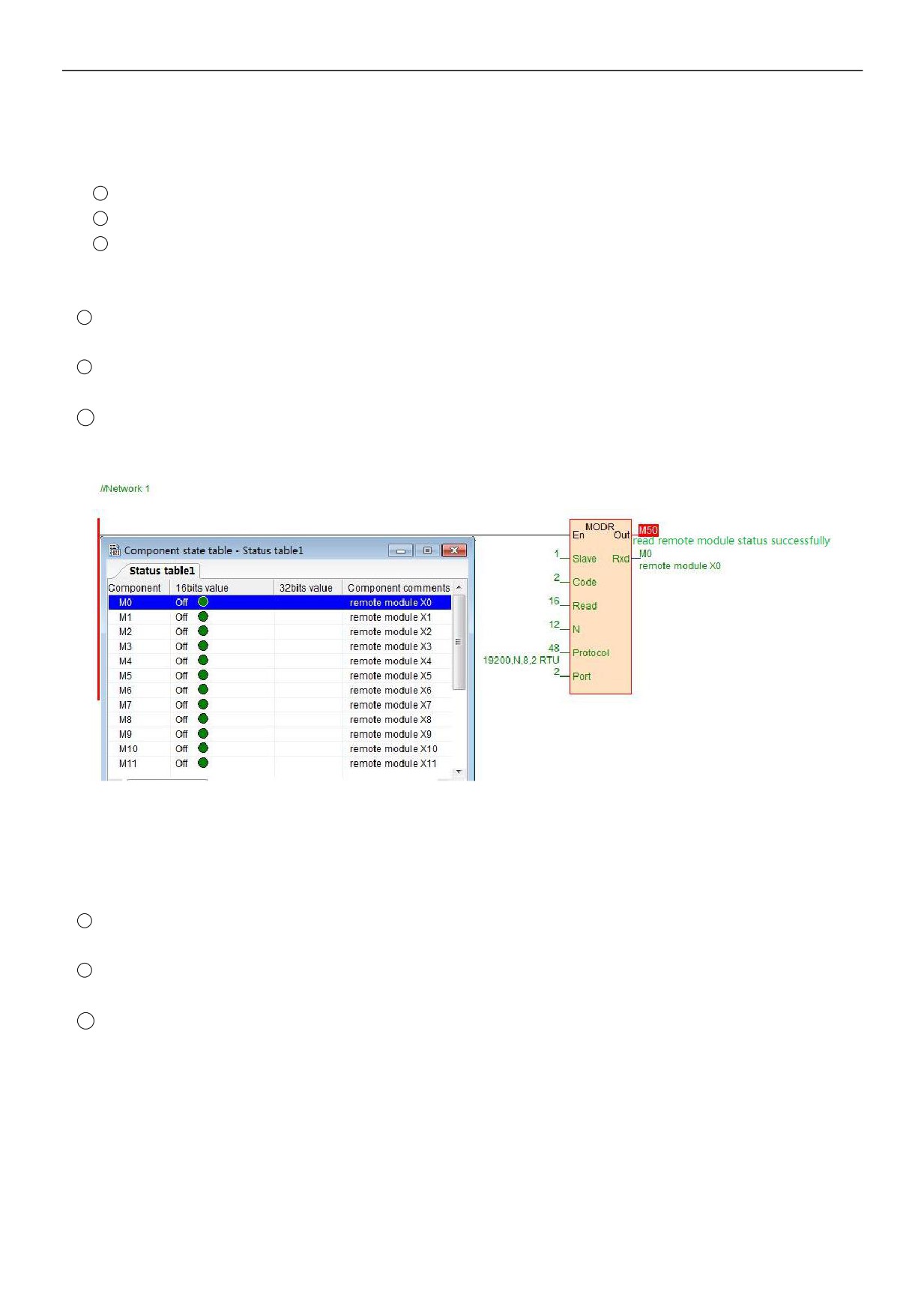
PLC program: Host PLC wants to read the 12 channels input status of remote IO module TE-12X12Y-TN. In this example,
TE-12X12Y-TN communication is the default parameter: Station number address is 1, baud rate is 19200, data format is N
8 2 RTU. The PLC reads the 12 channels input status of TE-12X12Y-TN module:
The host PLC reads the 12 channels input status of TE-12X12Y-TN by Modbus read instruction MODR, the start address is
10H (hexadecimal), that is, the decimal value is 16. When the communication is successful, M50 is ON, the input points
status which are read back will be stored in M0-M11.
1.7 Remote IO application example (RS485 mode): The PLC writes the 12-channel output values of TE-12X12Y-TN module
1
Hardware wiring: PLC connects to 485 port of module by shielded twisted pair, A + connects to A +, B- connects to B-, if the
PLC connects to multiple remote IO modules, it needs to use hand in hand way to connect.
2
Modbus address: From the above digital module CR parameter table shows that, the output channel 1 ~ 12 output values
of 12-channel module are stored in address 50H~5CH.
3
PLC program: Host PLC wants to write the 12-channel output values of remote IO module TE-12X12Y-TN. In this example,
TE-12X12Y-TN communication parameters: Station number address is 1, baud rate 19200, data format N 8 2 RTU. The
program of writing 12-channel output values of TE-12X12Y-TN is as follows:
10 / 11
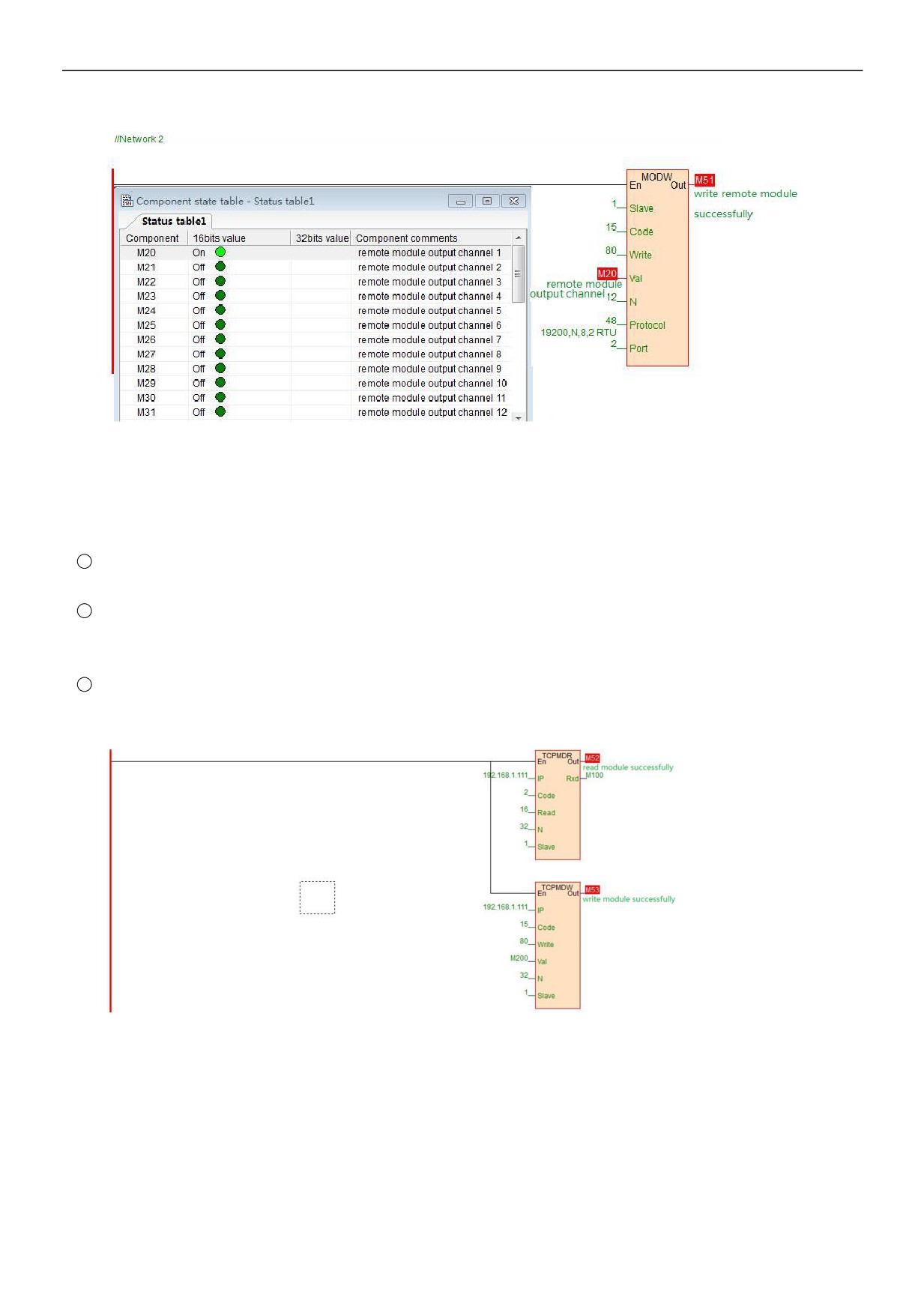
Host PLC writes the 12-channel output values of TE-12X12Y-TN by Modbus write instruction MODW, the start address is
50H(hexadecimal), that is, the decimal value is 80. When writing successfully, M51 is ON, the 12-channel values which will
be written into are stored in M20-M31.
1.8 Remote IO application example(Ethernet): PLC read and write each channel input and output values of TE-32X32Y-TNe
1
Hardware wiring: PLC and module Ethernet port connected with a shielded network cable, they can be connected directly
or through the switch.
2
Modbus address: From the above TE-32X32Y-TNe digital module CR parameter table shows that the input values of
module input channel 1 ~ 32 are stored in the address 10H~30H. The output values of module output channel 1-32 are
stored in 50H~70H.
3
PLC program: Read the 32-channel input status of remote Ethernet module TE-32X32Y-TNe and write the 32-channel
output values of TE-32X32Y-TNe, if the module IP address is 192.168.1.112, station number address is 1, the read results
are stored in the M100~M131, the values to be written are stored in the register M200-M231. As follows: